JP6750386B2 - Failure detection device for rotating electrical machine - Google Patents
Failure detection device for rotating electrical machine Download PDFInfo
- Publication number
- JP6750386B2 JP6750386B2 JP2016158556A JP2016158556A JP6750386B2 JP 6750386 B2 JP6750386 B2 JP 6750386B2 JP 2016158556 A JP2016158556 A JP 2016158556A JP 2016158556 A JP2016158556 A JP 2016158556A JP 6750386 B2 JP6750386 B2 JP 6750386B2
- Authority
- JP
- Japan
- Prior art keywords
- phase
- electric machine
- engine
- failure
- rotating electric
- Prior art date
- Legal status (The legal status is an assumption and is not a legal conclusion. Google has not performed a legal analysis and makes no representation as to the accuracy of the status listed.)
- Active
Links
Images


Classifications
-
- B—PERFORMING OPERATIONS; TRANSPORTING
- B60—VEHICLES IN GENERAL
- B60L—PROPULSION OF ELECTRICALLY-PROPELLED VEHICLES; SUPPLYING ELECTRIC POWER FOR AUXILIARY EQUIPMENT OF ELECTRICALLY-PROPELLED VEHICLES; ELECTRODYNAMIC BRAKE SYSTEMS FOR VEHICLES IN GENERAL; MAGNETIC SUSPENSION OR LEVITATION FOR VEHICLES; MONITORING OPERATING VARIABLES OF ELECTRICALLY-PROPELLED VEHICLES; ELECTRIC SAFETY DEVICES FOR ELECTRICALLY-PROPELLED VEHICLES
- B60L3/00—Electric devices on electrically-propelled vehicles for safety purposes; Monitoring operating variables, e.g. speed, deceleration or energy consumption
-
- B—PERFORMING OPERATIONS; TRANSPORTING
- B60—VEHICLES IN GENERAL
- B60L—PROPULSION OF ELECTRICALLY-PROPELLED VEHICLES; SUPPLYING ELECTRIC POWER FOR AUXILIARY EQUIPMENT OF ELECTRICALLY-PROPELLED VEHICLES; ELECTRODYNAMIC BRAKE SYSTEMS FOR VEHICLES IN GENERAL; MAGNETIC SUSPENSION OR LEVITATION FOR VEHICLES; MONITORING OPERATING VARIABLES OF ELECTRICALLY-PROPELLED VEHICLES; ELECTRIC SAFETY DEVICES FOR ELECTRICALLY-PROPELLED VEHICLES
- B60L50/00—Electric propulsion with power supplied within the vehicle
- B60L50/10—Electric propulsion with power supplied within the vehicle using propulsion power supplied by engine-driven generators, e.g. generators driven by combustion engines
- B60L50/16—Electric propulsion with power supplied within the vehicle using propulsion power supplied by engine-driven generators, e.g. generators driven by combustion engines with provision for separate direct mechanical propulsion
-
- B—PERFORMING OPERATIONS; TRANSPORTING
- B60—VEHICLES IN GENERAL
- B60W—CONJOINT CONTROL OF VEHICLE SUB-UNITS OF DIFFERENT TYPE OR DIFFERENT FUNCTION; CONTROL SYSTEMS SPECIALLY ADAPTED FOR HYBRID VEHICLES; ROAD VEHICLE DRIVE CONTROL SYSTEMS FOR PURPOSES NOT RELATED TO THE CONTROL OF A PARTICULAR SUB-UNIT
- B60W10/00—Conjoint control of vehicle sub-units of different type or different function
- B60W10/04—Conjoint control of vehicle sub-units of different type or different function including control of propulsion units
- B60W10/08—Conjoint control of vehicle sub-units of different type or different function including control of propulsion units including control of electric propulsion units, e.g. motors or generators
-
- B—PERFORMING OPERATIONS; TRANSPORTING
- B60—VEHICLES IN GENERAL
- B60W—CONJOINT CONTROL OF VEHICLE SUB-UNITS OF DIFFERENT TYPE OR DIFFERENT FUNCTION; CONTROL SYSTEMS SPECIALLY ADAPTED FOR HYBRID VEHICLES; ROAD VEHICLE DRIVE CONTROL SYSTEMS FOR PURPOSES NOT RELATED TO THE CONTROL OF A PARTICULAR SUB-UNIT
- B60W20/00—Control systems specially adapted for hybrid vehicles
- B60W20/50—Control strategies for responding to system failures, e.g. for fault diagnosis, failsafe operation or limp mode
-
- F—MECHANICAL ENGINEERING; LIGHTING; HEATING; WEAPONS; BLASTING
- F02—COMBUSTION ENGINES; HOT-GAS OR COMBUSTION-PRODUCT ENGINE PLANTS
- F02D—CONTROLLING COMBUSTION ENGINES
- F02D29/00—Controlling engines, such controlling being peculiar to the devices driven thereby, the devices being other than parts or accessories essential to engine operation, e.g. controlling of engines by signals external thereto
- F02D29/06—Controlling engines, such controlling being peculiar to the devices driven thereby, the devices being other than parts or accessories essential to engine operation, e.g. controlling of engines by signals external thereto peculiar to engines driving electric generators
-
- H—ELECTRICITY
- H02—GENERATION; CONVERSION OR DISTRIBUTION OF ELECTRIC POWER
- H02P—CONTROL OR REGULATION OF ELECTRIC MOTORS, ELECTRIC GENERATORS OR DYNAMO-ELECTRIC CONVERTERS; CONTROLLING TRANSFORMERS, REACTORS OR CHOKE COILS
- H02P27/00—Arrangements or methods for the control of AC motors characterised by the kind of supply voltage
- H02P27/04—Arrangements or methods for the control of AC motors characterised by the kind of supply voltage using variable-frequency supply voltage, e.g. inverter or converter supply voltage
- H02P27/06—Arrangements or methods for the control of AC motors characterised by the kind of supply voltage using variable-frequency supply voltage, e.g. inverter or converter supply voltage using dc to ac converters or inverters
-
- H—ELECTRICITY
- H02—GENERATION; CONVERSION OR DISTRIBUTION OF ELECTRIC POWER
- H02P—CONTROL OR REGULATION OF ELECTRIC MOTORS, ELECTRIC GENERATORS OR DYNAMO-ELECTRIC CONVERTERS; CONTROLLING TRANSFORMERS, REACTORS OR CHOKE COILS
- H02P29/00—Arrangements for regulating or controlling electric motors, appropriate for both AC and DC motors
- H02P29/02—Providing protection against overload without automatic interruption of supply
- H02P29/024—Detecting a fault condition, e.g. short circuit, locked rotor, open circuit or loss of load
- H02P29/0241—Detecting a fault condition, e.g. short circuit, locked rotor, open circuit or loss of load the fault being an overvoltage
Landscapes
- Engineering & Computer Science (AREA)
- Mechanical Engineering (AREA)
- Power Engineering (AREA)
- Transportation (AREA)
- Chemical & Material Sciences (AREA)
- Combustion & Propulsion (AREA)
- Life Sciences & Earth Sciences (AREA)
- Sustainable Development (AREA)
- Sustainable Energy (AREA)
- Health & Medical Sciences (AREA)
- General Engineering & Computer Science (AREA)
- Biomedical Technology (AREA)
- General Health & Medical Sciences (AREA)
- Automation & Control Theory (AREA)
- Hybrid Electric Vehicles (AREA)
- Electric Propulsion And Braking For Vehicles (AREA)
- Control Of Eletrric Generators (AREA)
- Inverter Devices (AREA)
- Control Of Electric Motors In General (AREA)
- Control Of Ac Motors In General (AREA)
Description
本発明は、回転電機の故障を検出する故障検出装置に関する。 The present invention relates to a failure detection device that detects a failure of a rotating electric machine.
従来、交流モータの出力トルクがトルク指令値よりも小さい場合に、矩形波電圧の電圧位相を予め定められた上限位相以下の範囲で増加させ、電圧位相が上限位相に所定時間継続して一致した場合に、インバータが異常であると検出するものがある(特許文献1参照)。特許文献1に記載のものでは、上限位相を一定値に予め定めている。これは、交流モータにおいて出力トルクが最大となる電圧位相は、一定値となるためである。 Conventionally, when the output torque of the AC motor is smaller than the torque command value, the voltage phase of the rectangular wave voltage is increased within a range equal to or less than a predetermined upper limit phase, and the voltage phase continuously matches the upper limit phase for a predetermined time. In some cases, there is one that detects that the inverter is abnormal (see Patent Document 1). In the technique disclosed in Patent Document 1, the upper limit phase is preset to a constant value. This is because the voltage phase at which the output torque is maximum in the AC motor has a constant value.
しかしながら、特許文献1に記載のものでは、電圧位相が上限位相に一致し、且つその状態が所定時間継続しなければ、インバータが異常であると検出することができない。このため、インバータの異常を早期に検出することができず、未だ改善の余地を残すものとなっている。 However, in the device described in Patent Document 1, it is not possible to detect that the inverter is abnormal unless the voltage phase matches the upper limit phase and the state does not continue for a predetermined time. Therefore, the abnormality of the inverter cannot be detected at an early stage, and there is still room for improvement.
本発明は、上記課題を解決するためになされたものであり、その主たる目的は、回転電機の故障を早期且つ正確に検出することのできる回転電機の故障検出装置を提供することにある。 The present invention has been made to solve the above problems, and a main object of the present invention is to provide a failure detecting device for a rotating electric machine that can detect a failure of the rotating electric machine early and accurately.
上記課題を解決するため、本発明は以下の手段を採用した。 In order to solve the above problems, the present invention employs the following means.
第1の手段は、
エンジン(20)と、
前記エンジンと動力伝達可能に連結された三相回転電機(30、130)と、
直流電源(40)と、
前記三相回転電機と前記直流電源との間で電力変換するインバータ(50)と、
前記エンジンの運転状態に基づいて、前記電力変換時に前記インバータの各相をオン・オフする位相を制御する位相制御部(60)と、
を備えているシステム(10、110)に適用される三相回転電機の故障検出装置(70)であって、
前記三相回転電機の正常時において、前記電力変換時に前記エンジンの運転状態に基づいて制御される前記位相を記憶している記憶部(71)と、
前記位相制御部により制御されている前記電力変換時の前記位相と、前記記憶部に記憶されている対応する前記電力変換時の前記位相との乖離量に基づいて、前記三相回転電機の故障を判定する故障判定部(72)と、
を備えていることを特徴とする。
The first means is
Engine (20),
A three-phase rotating electric machine (30, 130) connected to the engine so that power can be transmitted,
DC power supply (40),
An inverter (50) for converting electric power between the three-phase rotating electric machine and the DC power supply;
A phase control unit (60) for controlling a phase for turning on and off each phase of the inverter during the power conversion based on an operating state of the engine;
A failure detection device (70) for a three-phase rotating electric machine applied to a system (10, 110) including:
A storage unit (71) that stores the phase that is controlled based on the operating state of the engine during the power conversion during normal operation of the three-phase rotating electric machine;
A failure of the three-phase rotating electric machine based on the amount of deviation between the phase at the time of power conversion controlled by the phase control unit and the corresponding phase at the time of power conversion stored in the storage unit. A failure determination unit (72) for determining
It is characterized by having.
上記構成によれば、エンジンと三相回転電機とが動力伝達可能に連結されている。このため、例えば、エンジンの駆動力により三相回転電機に発電をさせたり、三相回転電機の駆動力によりエンジンの駆動力をアシストさせたりすることができる。インバータにより、三相回転電機と直流電源との間で電力変換される。位相制御部により、エンジンの運転状態に基づいて、電力変換時にインバータの各相をオンにする位相が制御される。 According to the above configuration, the engine and the three-phase rotating electric machine are connected so that power can be transmitted. Therefore, for example, the driving force of the engine can cause the three-phase rotating electric machine to generate power, and the driving force of the three-phase rotating electric machine can assist the driving force of the engine. Electric power is converted between the three-phase rotating electric machine and the DC power supply by the inverter. The phase control unit controls the phase in which each phase of the inverter is turned on during power conversion, based on the operating state of the engine.
ここで、三相回転電機が故障している場合は、電力変換時に制御される位相が、正常時の位相から乖離する。このため、位相制御部により制御されている電力変換時の位相と、記憶部に記憶されている正常時における対応する電力変換時の位相との乖離量に基づいて、三相回転電機の故障を判定することができる。さらに、記憶部には、三相回転電機の正常時において、電力変換時にエンジンの運転状態に基づいて制御される位相が記憶されている。このため、エンジンの運転状態を反映して三相回転電機の故障を判定することができ、三相回転電機の故障を早期且つ正確に検出することができる。 Here, when the three-phase rotating electric machine is out of order, the phase controlled during power conversion deviates from the normal phase. Therefore, the failure of the three-phase rotating electric machine is determined based on the amount of deviation between the phase at the time of power conversion controlled by the phase control unit and the corresponding phase at the time of normal power conversion stored in the storage unit. Can be determined. Further, the storage unit stores the phase controlled based on the operating state of the engine during power conversion during normal operation of the three-phase rotating electric machine. Therefore, the failure of the three-phase rotating electric machine can be determined by reflecting the operating state of the engine, and the failure of the three-phase rotating electric machine can be detected early and accurately.
なお、インバータの各相をオン・オフする位相は、位相を補正する補正量(制御量)を含む。三相回転電機は、発電及び駆動の少なくとも一方を行うものであればよい。 The phase for turning on/off each phase of the inverter includes a correction amount (control amount) for correcting the phase. The three-phase rotating electric machine only needs to generate and/or drive power.
(第1実施形態)
以下、自動二輪車(車両)に搭載されたシステムとして具現化した第1実施形態について、図面を参照しつつ説明する。
(First embodiment)
Hereinafter, a first embodiment embodied as a system mounted on a motorcycle (vehicle) will be described with reference to the drawings.
図1に示すように、システム10は、エンジン20、MG(Motor Generator)30、直流電源40、インバータ50、電圧位相制御量演算部60、故障検出装置70、複数の補機80等を備えている。
As shown in FIG. 1, the
エンジン20は、燃料を燃焼させることにより動力を発生する。エンジン20として、ガソリンエンジンや、ディーゼルエンジン、及びその他のエンジンを採用することができる。
The
MG30(三相回転電機に相当)は、スタータ機能付き発電機である。MG30は、三相交流モータ及び三相交流発電機の機能を備えている。MG30は、ステータ巻線として、U相巻線31、V相巻線32、W相巻線33を備えている。U相巻線31,V相巻線32,W相巻線33の一端が中性点に共通接続されている。MG30の回転子は、磁石を備えており、エンジン20のクランクシャフトに直接連結されている。すなわち、エンジン20とMG30とは、動力伝達可能に連結されている。MG30には、回転子の角度位置を検出する角度位置センサ36が取り付けられている。
MG30 (corresponding to a three-phase rotating electric machine) is a generator with a starter function. The MG 30 has the functions of a three-phase AC motor and a three-phase AC generator. The MG 30 includes a U-phase winding 31, a V-phase winding 32, and a W-phase winding 33 as stator windings. One ends of the U-phase winding 31, the V-phase winding 32, and the W-
直流電源40は、Pbバッテリ、Liイオンバッテリ、NiHバッテリ等からなる二次電池やキャパシタ等である。直流電源40の電圧Vdcは、電圧センサ(図示略)により検出される。MG30の発電時には、電圧センサはMG30の発電電圧を検出する。
The
MG30と直流電源40との間には、インバータ50が接続されている。インバータ50は、U相アーム、V相アーム、W相アームを含む周知の三相インバータである。各相アームは、直流電源40の正極と負極との間に直列接続された2つのスイッチング素子を含んでいる。スイッチング素子に対して、逆並列にダイオードがそれぞれ接続されている。スイッチング素子のオン・オフは、電圧位相制御量演算部60から求まる電圧位相制御量に基づき演算される印加電圧Vu,Vv,Vw(印加電圧指令値)によって制御される。各相アームの中間点は、MG30の各相の巻線31,32,33の各相端に接続されている。
直流電源40及びインバータ50には、複数の補機80が接続されている。補機80は、車両のヘッドライト、ヘッドライトのハイビームとロービームとを切り替えるディマースイッチ、ウインカー、ブレーキランプ、ホーン(警笛機)等を含んでいる。
A plurality of
電圧位相制御量演算部60及び故障検出装置70は、CPU、ROM、RAM、入出力インターフェース等を備えるECUにより構成されている。ECUとして、MG30を制御するMGECU、エンジン20を制御するエンジンECU、MGECU及びエンジンECUを制御する上位のハイブリッドECU等を採用することができる。
The voltage phase control
電圧位相制御量演算部60には、MG30の回転子の角度位置θを微分した角速度ω、すなわちMG30の回転子に直接連結されたクランクシャフトの回転速度NEが入力される。電圧位相制御量演算部60には、電圧センサにより検出された電圧Vdcが入力される。
The voltage phase control
電圧位相制御量演算部60(位相制御部に相当)は、図2のフローチャートに示す手順により、電圧位相制御量を演算する。この一連の処理は、電圧位相制御量演算部60によって、所定の周期で繰り返し実行される。ここでは、MG30が発電を実行する場合を例に説明する。MG30が発電を実行する場合は、インバータ50の各相を回転子の回転角度(電気角度)で180°の期間オンにし、180°の期間オフにすることを繰り返す。
The voltage phase control amount calculation unit 60 (corresponding to the phase control unit) calculates the voltage phase control amount according to the procedure shown in the flowchart of FIG. This series of processing is repeatedly executed by the voltage phase control
まず、電圧位相制御量に初期値を設定する(S11)。電圧位相制御量は、磁極位置センサ信号に対する印加電圧Vu、Vv、Vwの進遅角量である。初期値は、MG30の正常時におけるエンジン20のアイドリング時の電圧位相制御量である。
First, an initial value is set for the voltage phase control amount (S11). The voltage phase control amount is the amount of advance/retard of the applied voltages Vu, Vv, Vw with respect to the magnetic pole position sensor signal. The initial value is the voltage phase control amount when the
続いて、目標発電電圧が現在の発電電圧よりも高いか否か判定する(S12)。目標発電電圧は、1つ以上の補機80の動作状態、すなわち補機80の電気負荷に基づいて設定される。例えば、動作している補機80の数が多いほど、電気負荷が大きくなり、目標発電電圧が高く設定される。発電電圧は、上述した電圧センサにより検出される。
Then, it is determined whether the target power generation voltage is higher than the current power generation voltage (S12). The target generated voltage is set based on the operating state of one or more
目標発電電圧が現在の発電電圧よりも高いと判定した場合(S12:YES)、遅角加算量を演算する(S13)。遅角加算量は、磁極位置センサ信号に対し印加電圧Vu、Vv、Vwの位相を遅角させる量である。スイッチングを遅角させることにより、発電量を増加させることができる。また、目標発電電圧と現在の発電電圧との差ΔV(差ΔV=目標発電電圧−現在の発電電圧)と、遅角加算量との関係が、予めテーブルに設定されている。このテーブルを参照して、差ΔVに基づいて遅角加算量を演算する。このテーブルは、エンジン20の回転速度NEに応じて設定されていてもよい。
When it is determined that the target power generation voltage is higher than the current power generation voltage (S12: YES), the retard addition amount is calculated (S13). The retard addition amount is an amount that retards the phases of the applied voltages Vu, Vv, and Vw with respect to the magnetic pole position sensor signal. By retarding the switching, the amount of power generation can be increased. Further, the relationship between the difference ΔV between the target power generation voltage and the current power generation voltage (difference ΔV=target power generation voltage−current power generation voltage) and the delay angle addition amount is set in advance in the table. With reference to this table, the retard addition amount is calculated based on the difference ΔV. This table may be set according to the rotation speed NE of the
続いて、S11で設定した電圧位相制御量に遅角加算量を加算して、電圧位相制御量を演算する(S14)。そして、この一連の処理を一旦終了する(END)。 Subsequently, the delay angle addition amount is added to the voltage phase control amount set in S11 to calculate the voltage phase control amount (S14). Then, this series of processing is once ended (END).
一方、目標発電電圧が現在の発電電圧よりも高くないと判定した場合(S12:NO)、進角加算量を演算する(S15)。進角加算量は、磁極位置センサ信号に対し印加電圧Vu、Vv、Vwの位相を進角させる量である。スイッチングを進角させることにより、発電量を減少させることができる。また、目標発電電圧と現在の発電電圧との差ΔVと、進角加算量との関係が、予めテーブルに設定されている。このテーブルを参照して、差ΔVに基づいて進角加算量を演算する。このテーブルは、エンジン20の回転速度NEに応じて設定されていてもよい。
On the other hand, when it is determined that the target power generation voltage is not higher than the current power generation voltage (S12: NO), the advance angle addition amount is calculated (S15). The advanced angle addition amount is an amount by which the phases of the applied voltages Vu, Vv, and Vw are advanced with respect to the magnetic pole position sensor signal. The amount of power generation can be reduced by advancing the switching. Further, the relationship between the difference ΔV between the target power generation voltage and the current power generation voltage and the amount of advance angle addition is set in advance in the table. With reference to this table, the advance addition amount is calculated based on the difference ΔV. This table may be set according to the rotation speed NE of the
続いて、S11で設定した電圧位相制御量から進角加算量を減算して、電圧位相制御量を演算する(S16)。そして、この一連の処理を一旦終了する(END)。故障検出装置70は、記憶部71と故障判定部72とを備えている。
Then, the advance addition amount is subtracted from the voltage phase control amount set in S11 to calculate the voltage phase control amount (S16). Then, this series of processing is once ended (END). The
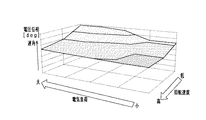
記憶部71は、不揮発性のメモリであり、ROM、書き換え可能な不揮発性メモリ、バックアップRAM等により構成されている。記憶部71は、MG30の正常時において、インバータ50による電力変換時にエンジン20の運転状態に基づいて制御される電圧位相を記憶している。詳しくは、図3に示すように、MG30の正常時において予め試験等により、電気負荷の大きさとエンジン20の回転速度NEとインバータ50の電圧位相との関係が測定されて記憶されている。すなわち、エンジン運転状態は、補機80の電気負荷と、エンジン20の回転速度NEとを含んでいる。また、記憶部71は、後述する電圧位相制御量の乖離量、及び/もしくは、電圧位相制御量の乖離量の変化速度に対する異常判定閾値を記憶している。
The
ここでは、MG30が発電を実行する場合を例に示している。電気負荷が大きいほど、エンジン20の回転速度NEが低いほど、インバータ50の電圧位相制御量は遅角している。電圧位相制御量(電圧位相)は、U相,V相,W相の少なくとも1つについて記憶されていればよい。
Here, the case where
故障判定部72は、図4のフローチャートに示す手順により、MG30の故障を検出する。ここでは、MG30が発電を実行する場合を例に説明する。この一連の処理は、MG30による発電時に、故障判定部72によって所定の周期で繰り返し実行される。
The
まず、現在の電圧位相制御量と正常時の対応する電圧位相制御量との乖離量を演算する(S21)。正常時の電圧位相制御量は、記憶部71に記憶されている図3のマップにおいて、エンジン20の現在の運転状態に対応する電圧位相制御量を読み出すことで取得する。現在の電圧位相制御量は、電圧位相制御量演算部60がエンジン20の現在の運転状態においてインバータ50の制御に用いている電圧位相制御量を、電圧位相制御量演算部60から入力することで取得する。そして、現在の電圧位相制御量から正常時の電圧位相制御量を減算することで、乖離量を演算する(乖離量=現在の電圧位相制御量−正常時の電圧位相制御量)。
First, the amount of deviation between the current voltage phase control amount and the corresponding voltage phase control amount under normal conditions is calculated (S21). The normal voltage phase control amount is acquired by reading the voltage phase control amount corresponding to the current operating state of the
続いて、S21で演算した乖離量が異常判定閾値よりも大きいか否か判定する(S22)。異常判定閾値(所定量に相当)は、MG30の正常時には生じ得ない所定の乖離量に設定されている。この判定において、乖離量が異常判定閾値よりも大きいと判定した場合(S22:YES)、MG30が異常であると確定する(S23)。すなわち、MG30が故障していると判定する。具体的には、異常判定フラグをオンに設定する。MG30の故障としては、巻線31〜33のいずれかの断線、短絡等が考えられる。そして、この一連の処理を一旦終了する(END)。
Then, it is determined whether the deviation amount calculated in S21 is larger than the abnormality determination threshold value (S22). The abnormality determination threshold value (corresponding to a predetermined amount) is set to a predetermined deviation amount that cannot occur when the
一方、S22の判定において、乖離量が異常判定閾値よりも大きくないと判定した場合(S22:NO)、MG30が異常であると確定することは行わない(S24)。具体的には、異常判定フラグをオフに設定する。この場合に、乖離量の大きさに応じて、MG30が異常の可能性ありと判定したり、MG30が異常であると仮判定したりしてもよい。そして、この一連の処理を一旦終了する(END)。
On the other hand, in the determination of S22, when it is determined that the deviation amount is not larger than the abnormality determination threshold value (S22: NO), it is not determined that the
図5は、本実施形態の故障検出の一例を示すタイムチャートである。 FIG. 5 is a time chart showing an example of failure detection according to this embodiment.
時刻t1よりも前では、補機80の電気負荷に基づいて電圧位相制御量が演算され、電圧位相制御量の実際の制御量と正常時データとが一致している。このため、実際の電圧位相制御量と正常時の電圧位相制御量との乖離量は略0になる。そして、異常判定フラグはオフに設定される。
Before the time t1, the voltage phase control amount is calculated based on the electric load of the
時刻t1において、例えばMG30のU相巻線に断線が生じると、現在の発電電圧が目標発電電圧よりも低くなり、遅角加算量が増加される。そして、電圧位相制御量の初期値に遅角加算量が加算されて、電圧位相制御量が増加する。その結果、実際の電圧位相制御量と正常時の電圧位相制御量との乖離量が増加する。 At time t1, for example, if the U-phase winding of MG30 is disconnected, the current power generation voltage becomes lower than the target power generation voltage, and the retard addition amount is increased. Then, the retard addition amount is added to the initial value of the voltage phase control amount, and the voltage phase control amount increases. As a result, the amount of deviation between the actual voltage phase control amount and the normal voltage phase control amount increases.
時刻t2において、実際の電圧位相制御量と正常時の電圧位相制御量との乖離量が異常判定閾値よりも大きくなると、MG30が異常であると確定される。そして、異常判定フラグがオンに設定される。
At time t2, when the deviation amount between the actual voltage phase control amount and the normal voltage phase control amount becomes larger than the abnormality determination threshold value,
以上詳述した本実施形態は、以下の利点を有する。 The embodiment described in detail above has the following advantages.
・MG30が故障している場合は、インバータ50による電力変換時に制御される位相が、正常時の位相から乖離する。このため、電圧位相制御量演算部60により制御されている電力変換時の位相と、記憶部71に記憶されている正常時における対応する電力変換時の位相との乖離量に基づいて、MG30の故障を判定することができる。さらに、記憶部71には、MG30の正常時において、電力変換時にエンジン20の運転状態に基づいて制御される位相が記憶されている。このため、エンジン20の運転状態を反映してMG30の故障を判定することができ、MG30の故障を早期且つ正確に検出することができる。
When the
・故障判定部72により、制御されている位相と正常時における位相との乖離量が異常判定閾値よりも大きい場合に、MG30が故障していると判定される。このため、MG30の故障を、簡易に検出することができる。
The
・MG30により発電される発電電圧は、エンジン20の回転速度NEに応じて変化する。このため、電力変換時にインバータ50の各相をオンにする位相も、エンジン20の回転速度NEに応じて変化する。この点、記憶部71には、MG30の正常時において電力変換時に制御される位相が、エンジン20の回転速度NEに応じて記憶されている。したがって、エンジン20の回転速度NEを反映して、MG30の故障を正確に判定することができる。
The power generation voltage generated by the
・MG30が発電する際の目標発電電圧は、補機80の電気負荷に応じて変化する。このため、電力変換時にインバータ50の各相をオンにする位相も、複数の補機80の電気負荷に応じて変化する。この点、記憶部71には、MG30の正常時において電力変換時に制御される位相が、補機80の電気負荷に応じて記憶されている。したがって、補機80の電気負荷を反映して、MG30の故障を正確に判定することができる。
The target power generation voltage when the
なお、第1実施形態を、以下のように変更して実施することもできる。 The first embodiment may be modified and implemented as follows.
・故障判定部72は、制御されている位相と正常時における位相との乖離量の変化速度が異常判定閾値よりも高い場合に、MG30が故障していると判定することもできる。
The
図6は、こうした故障検出の手順を示すフローチャートである。ここでは、S31において、図4のS21と同様に演算した乖離量の変化速度を演算する。乖離量の変化速度は、今回演算した乖離量から前回演算した乖離量を減算することで演算する。続いて、S31で演算した乖離量の変化速度が異常判定閾値よりも大きいか否か判定する(S32)。乖離量の変化速度に関する異常判定閾値(所定変化速度に相当)は、MG30の正常時には生じ得ない所定の変化速度に設定されている。S33及びS34の処理は、それぞれ図4のS23及びS24の処理と同一である。
FIG. 6 is a flowchart showing the procedure of such failure detection. Here, in S31, the change speed of the deviation amount calculated as in S21 of FIG. 4 is calculated. The change speed of the deviation amount is calculated by subtracting the deviation amount calculated last time from the deviation amount calculated this time. Then, it is determined whether the change speed of the deviation amount calculated in S31 is larger than the abnormality determination threshold value (S32). The abnormality determination threshold value (corresponding to a predetermined change speed) regarding the change speed of the deviation amount is set to a predetermined change speed that cannot occur when the
図7は、上記故障検出の一例を示すタイムチャートである。時刻t1までの動作は、図5と同一である。そして、図5の時刻t2よりも前の時刻t3において、乖離量の変化速度が異常判定閾値よりも高くなると、MG30が異常であると確定される。そして、異常判定フラグがオンに設定される。上記構成によれば、乖離量が急激に大きくなる場合に、MG30の故障を早期に検出することができる。
FIG. 7 is a time chart showing an example of the failure detection. The operation up to time t1 is the same as in FIG. Then, at time t3 before time t2 in FIG. 5, when the change speed of the deviation amount becomes higher than the abnormality determination threshold value,
(第2実施形態)
以下、第2実施形態について、第1実施形態との相違点を中心に説明する。第1実施形態と同一の部材については、第1実施形態と同一の符号を付すことにより説明を省略する。
(Second embodiment)
Hereinafter, the second embodiment will be described focusing on the differences from the first embodiment. The same members as those in the first embodiment are designated by the same reference numerals as those in the first embodiment, and the description thereof will be omitted.
図8は、本実施形態のシステム110の概略を示すブロック図である。
FIG. 8 is a block diagram showing an outline of the
MG130は、巻線31A,32A,33Aの第1組と、巻線31B,32B,33Bの第2組とを備えている。巻線31A,32A,33Aの巻数は、巻線31B,32B,33Bの巻数よりも多くなっている。そして、MG130は、インバータ50に接続する三相巻線の組を第1組と第2組とで切替可能になっている。具体的には、MG130は、巻線31Aと巻線31Bとを切り替える切替部37、巻線32Aと巻線32Bとを切り替える切替部38、及び巻線33Aと巻線33Bとを切り替える切替部39を備えている。切替部37,38,39の動作は、巻線切替制御部65により制御される。
巻線切替制御部65は、電圧位相制御量演算部60及び故障検出装置70と同様に、MG30を制御するMGECU、エンジン20を制御するエンジンECU、MGECU及びエンジンECUを制御する上位のハイブリッドECU等により構成されている。巻線切替制御部65は、エンジン20の回転速度NEが所定回転速度よりも低い場合に、インバータ50に接続する巻線を切替部37,38,39によりそれぞれ巻線31A,32A,33Aに切り替えさせる。巻線切替制御部65は、エンジン20の回転速度NEが所定回転速度よりも高い場合に、インバータ50に接続する巻線を切替部37,38,39によりそれぞれ巻線31B,32B,33Bに切り替えさせる。
The winding
記憶部71は、MG130の正常時において、インバータ50による電力変換時にエンジン20の運転状態に基づいて制御される電圧位相を、三相巻線の組毎に記憶している。詳しくは、図10に示すように、MG30の正常時において予め試験等により、インバータ50に巻線31A,32A,33Aが接続された状態で、電気負荷の大きさとエンジン20の回転速度NEとインバータ50の電圧位相との関係が測定されて記憶されている。また、図11に示すように、MG30の正常時において予め試験等により、インバータ50に巻線31B,32B,33Bが接続された状態で、電気負荷の大きさとエンジン20の回転速度NEとインバータ50の電圧位相との関係が測定されて記憶されている。すなわち、エンジン運転状態は、補機80の電気負荷と、エンジン20の回転速度NEとを含んでいる。
本実施形態では、故障判定部72は、図4,6に示す故障検出を実行する際に、インバータ50に接続されている三相巻線の組における正常時の電圧位相制御量のデータを参照する。図9は、正常時参照データ決定の手順を示すフローチャートである。この一連の処理は、故障判定部72により、所定の周期で繰り返し実行される。
In the present embodiment, the
まず、三相巻線の組を切り替える前であるか否か判定する(S41)。詳しくは、巻線切替制御部65により、三相巻線の組が巻線31B,32B,33Bに切り替えられていないか否か判定する。この判定において、三相巻線の組を切り替える前であると判定した場合(S41:YES)、三相巻線の組を切り替える前の正常時の電圧位相制御量を参照データに決定する(S42)。すなわち、図10に示すインバータ50に巻線31A,32A,33Aが接続された状態での電気負荷の大きさとエンジン20の回転速度NEとインバータ50の電圧位相との関係を、参照データに決定する。その後、この一連の処理を一旦終了する(END)。
First, it is determined whether it is before switching the set of three-phase windings (S41). Specifically, the winding
一方、S41の判定において、三相巻線の組を切り替える前でないと判定した場合(S41:NO)、三相巻線の組を切り替えた後の正常時の電圧位相制御量を参照データに決定する(S43)。すなわち、図11に示すインバータ50に巻線31B,32B,33Bが接続された状態での電気負荷の大きさとエンジン20の回転速度NEとインバータ50の電圧位相との関係を、参照データに決定する。その後、この一連の処理を一旦終了する(END)。
On the other hand, in the determination of S41, when it is determined that it is not before switching the set of three-phase windings (S41: NO), the voltage phase control amount at the normal time after switching the set of three-phase windings is determined as reference data. Yes (S43). That is, the relationship between the magnitude of the electric load, the rotational speed NE of the
本実施形態によれば、巻線31A,32A,33Aの第1組と、巻線31B,32B,33Bの第2組とを備え、インバータ50に接続する三相巻線の組を切替部37,38,39により切替可能である。記憶部71には、MG130の正常時において、電力変換時にエンジン20の運転状態に基づいて制御される位相が三相巻線の組毎に記憶されている。そして、インバータ50に接続されている組において、電圧位相制御量演算部60により制御されている電力変換時の位相と、記憶部71に記憶されている対応する電力変換時の位相との乖離量に基づいて、MG130の故障が判定される。したがって、MG130が備えている三相巻線の各組について、故障を早期且つ正確に検出することができる。
According to the present embodiment, the switching
なお、第1及び第2実施形態を、以下のように変更して実施することもできる。 The first and second embodiments can be modified and implemented as follows.
・エンジン20の回転速度NEを、エンジン20のクランク角を検出するクランク角センサの検出値に基づいて演算することもできる。また、エンジン20の運転状態として、エンジン20の回転速度NEに代えて、回転速度NEに演算処理を行った値や、エンジン20が備えるカムシャフトの回転速度を用いることもできる。
The rotation speed NE of the
・図4のS22又は図6のS32の判定が肯定された時点からカウンタを加算して、カウント値が所定カウント値を超えたことを条件として、MG30が異常であると確定してもよい。すなわち、図4のS22又は図6のS32の判定が所定時間肯定されたことを条件として、MG30が異常であると確定してもよい。第2実施形態では、図4,6に示す故障検出を実行する際に、参照する正常時の電圧位相制御量のデータが、インバータ50に接続されている三相巻線の組に応じて切り替えられる。そこで、三相巻線の組毎にカウンタを設定するとよい。こうした構成によれば、カウンタによるカウント中に、インバータ50に接続されている三相巻線の組が切り替えられたとしても、切り替え前のカウンタにおいてカウント値を保持することができる。そして、各組のカウンタによるカウント値に基づいて、各組の三相巻線の断線等を検出することができる。
The counter may be added from the time when the determination of S22 of FIG. 4 or S32 of FIG. 6 is affirmed, and MG30 may be determined to be abnormal on the condition that the count value exceeds the predetermined count value. That is, the
・MG30が直流電源40から供給される電力によりエンジン20の駆動力をアシストする場合、すなわちMG30が駆動(力行)を実行する場合に、MG30の故障を検出することもできる。この場合、図2の進遅角制御に代えて、目標駆動トルクに基づく電圧位相制御量の進遅角制御を実行する。詳しくは、MG30が駆動を実行する場合も、インバータ50の各相を回転子の回転角度(電気角度)で180°の期間オンにし、180°の期間オフにすることを繰り返す(矩形波電圧制御)。また180°の間でオンオフを繰り返す、正弦波駆動制御、過変調駆動制御や、オン期間が120°となる120度通電制御を用いてもよい。そして、目標駆動トルクが現在のMG30の駆動トルクよりも大きい場合に電圧位相制御量を進角させ、目標駆動トルクが現在のMG30の駆動トルクよりも小さい場合に電圧位相制御量を遅角させる。さらに、図3の電気負荷を電源電圧に、遅角量を進角量に代えた関係を予め測定しておき、図4及び図6の少なくとも一方の故障検出を実行すればよい。
The failure of
モータのトルクTはT=p・Φ・iqで求めることができる。pは磁極対数、Φは誘起電圧定数、iqはq軸電流である。p、Φは固定となるため、トルクはiqを用いて簡易的に求めることができる。iqは、電圧位相制御量、電源電圧、モータ回転速度に基づき予め設定されたマップを参照することで求めることができる。 The torque T of the motor can be calculated by T=p·Φ·iq. p is the number of magnetic pole pairs, Φ is the induced voltage constant, and iq is the q-axis current. Since p and Φ are fixed, the torque can be easily obtained using iq. The iq can be obtained by referring to a preset map based on the voltage phase control amount, the power supply voltage, and the motor rotation speed.
図12のフローチャートを用いて動作を具体的に説明する。まず電圧位相制御量に初期値を設定する(S51)。初期値としては、MG30の正常時におけるエンジン20のアイドリング時の電圧位相制御量を設定する。
The operation will be specifically described with reference to the flowchart of FIG. First, an initial value is set for the voltage phase control amount (S51). As the initial value, the voltage phase control amount when the
続いて、目標トルクが現在トルクよりも高いか否かを判定する(S52)。目標トルクが現在のトルクよりも高いと判定した場合(S52:YES)、進角加算量を演算する(S53)。進角加算量は、磁極位置センサ信号に対し印加電圧Vu、Vv、Vwの位相を進角させる量である。目標トルクと現在トルクとの差ΔT(差Δ=目標トルク−現在トルク)と、進角加算量との関係が、予めテーブルに設定されている。このテーブルを参照して、差ΔTに基づいて進角加算量を演算する。このテーブルは、エンジン20の回転速度NEに応じて設定されていてもよい。
Then, it is determined whether the target torque is higher than the present torque (S52). When it is determined that the target torque is higher than the current torque (S52: YES), the advance angle addition amount is calculated (S53). The advanced angle addition amount is an amount by which the phases of the applied voltages Vu, Vv, and Vw are advanced with respect to the magnetic pole position sensor signal. The relationship between the difference ΔT between the target torque and the current torque (difference Δ=target torque-current torque) and the amount of advance angle addition is set in advance in the table. With reference to this table, the advance addition amount is calculated based on the difference ΔT. This table may be set according to the rotation speed NE of the
続いて、電圧位相制御量に進角加算量を加算して、電圧位相制御量を演算する(S54)。そして、この一連の処理を一旦終了する(END)。 Then, the advance angle addition amount is added to the voltage phase control amount to calculate the voltage phase control amount (S54). Then, this series of processing is once ended (END).
一方、目標トルクが現在トルクよりも高くないと判定した場合(S52:NO)、遅角加算量を演算する(S55)。遅角加算量は、磁極位置センサ信号に対し印加電圧Vu、Vv、Vwの位相を遅角させる量である。目標トルクと現在トルクとの差ΔTと、遅角加算量との関係が、予めテーブルに設定されている。このテーブルを参照して、差ΔTに基づいて遅角加算量を演算する。このテーブルは、エンジン20の回転速度NEに応じて設定されてもよい。
On the other hand, when it is determined that the target torque is not higher than the current torque (S52: NO), the retard addition amount is calculated (S55). The retard addition amount is an amount that retards the phases of the applied voltages Vu, Vv, and Vw with respect to the magnetic pole position sensor signal. The relationship between the difference ΔT between the target torque and the current torque and the retard addition amount is preset in the table. With reference to this table, the retard addition amount is calculated based on the difference ΔT. This table may be set according to the rotation speed NE of the
続いて、電圧位相制御量から遅角加算量を減算して、電圧位相制御量を演算する(S56)。そして、この一連の処理を一旦終了する(END)。 Subsequently, the delay angle addition amount is subtracted from the voltage phase control amount to calculate the voltage phase control amount (S56). Then, this series of processing is once ended (END).
MG30が力行する場合、電源電圧が低いほど、エンジン20の回転速度が高いほど、インバータ50の電圧位相制御量は進角する。
When the
そして発電制御同様、図4または図6のフローチャートに示す手順により、MG30の故障を検出する。
Then, similarly to the power generation control, the failure of the
例えば、MG30のU相巻線に断線が生じると、現在トルクが目標トルクよりも低くなり、進角加算量が増加される。そして、電圧位相制御量の初期値に進角加算量が加算され、電圧位相制御量が増加する。その結果、実際の電圧位相制御量と正常時の電圧位相制御量との乖離量が増加する。実際の電圧位相制御量と正常時の電圧位相制御量との乖離量が異常判定閾値よりも大きくなると、MG30が異常であると確定される。そして異常判定フラグがオンになる。
For example, if the U-phase winding of MG30 is broken, the current torque becomes lower than the target torque, and the amount of advance angle addition is increased. Then, the advance addition amount is added to the initial value of the voltage phase control amount, and the voltage phase control amount increases. As a result, the amount of deviation between the actual voltage phase control amount and the normal voltage phase control amount increases. When the deviation amount between the actual voltage phase control amount and the normal voltage phase control amount becomes larger than the abnormality determination threshold value,
・三相回転電機による発電の実行時に三相回転電機の故障を検出する場合は、三相回転電機としてMG、オルタネータを採用することができる。三相回転電機による駆動の実行時に三相回転電機の故障を検出する場合は、三相回転電機としてMG、モータを採用することができる。 -When a failure of the three-phase rotating electric machine is detected during the power generation by the three-phase rotating electric machine, an MG or an alternator can be adopted as the three-phase rotating electric machine. When a failure of the three-phase rotating electric machine is detected when the three-phase rotating electric machine is driven, an MG or a motor can be used as the three-phase rotating electric machine.
以上、本発明のそれぞれの実施形態について説明したが、本発明は上記実施形態に限定されるものではなく、その要旨を逸脱しない範囲において種々の実施形態に適用することができる。 Although the respective embodiments of the present invention have been described above, the present invention is not limited to the above-described embodiments and can be applied to various embodiments without departing from the gist thereof.
例えば、変形例1として、現在の電圧位相制御量と正常時の対応する電圧位相制御量との乖離量が異常判定閾値よりも大きくなった際、仮判定として一旦保留し、現在制御されている位相と正常時における位相との乖離量の変化速度が異常判定閾値よりも高くなった際に本判定として異常と判定することもできる。 For example, as a modified example 1, when the deviation amount between the current voltage phase control amount and the corresponding voltage phase control amount in the normal state becomes larger than the abnormality determination threshold value, it is temporarily held as a temporary determination and is currently controlled. When the change speed of the amount of deviation between the phase and the normal phase becomes higher than the abnormality determination threshold value, it is possible to determine the abnormality as the main determination.
このとき、記憶部71には正常時においてインバータによる電力変換時にエンジン20の運転状態に基づいて制御される電圧位相と、その電圧位相の変化速度を記憶している。
At this time, the
この記憶部71に記憶されている電圧位相、及び電圧位相の変化速度に基づいて、閾値が決定され、図4、及び図6に示されるようなフローチャートにしたがって各判定は行われる。
The threshold value is determined based on the voltage phase and the change rate of the voltage phase stored in the
また、変形例2として、上記変形例1の仮判定と本判定の順序を逆にすることもできる。すなわち、乖離量の変化速度が異常判定閾値よりも高くなった際に、仮判定として一旦保留し、さらに現在の電圧位相制御量と正常時の対応する電圧位相制御量との乖離量が異常判定閾値よりも大きくなった際に本判定として異常と判定することができる。 Further, as a second modification, the order of the temporary judgment and the main judgment of the first modification can be reversed. That is, when the rate of change of the deviation amount becomes higher than the abnormality determination threshold value, it is temporarily suspended as a temporary determination, and the deviation amount between the current voltage phase control amount and the corresponding voltage phase control amount at the normal time is determined to be abnormal. When the value becomes larger than the threshold value, it can be determined as abnormal as the main determination.
変形例2によれば、乖離量の変化速度が大きくなり、瞬間的に乖離量の変化速度が異常判定閾値を超えたとしても、すぐに異常であると判定せず、現在の電圧位相制御量と正常時の対応する電圧位相制御量との乖離量が異常判定閾値よりも大きくなった際に本判定として異常を判定するので、より精度の高い異常判定を行うことができる。 According to the second modification, even if the change rate of the deviation amount increases and the change rate of the deviation amount momentarily exceeds the abnormality determination threshold value, the current voltage phase control amount is not determined to be abnormal immediately. Since the abnormality is determined as the main determination when the amount of deviation from the corresponding voltage phase control amount in the normal state becomes larger than the abnormality determination threshold, it is possible to perform the abnormality determination with higher accuracy.
これにより、搭乗者へ意図しない異常を伝達することを抑制することができ、回転電機の故障を正確に判定することが可能となる。 As a result, it is possible to suppress the transmission of an unintended abnormality to the passenger, and it is possible to accurately determine the failure of the rotating electric machine.
10…システム、20…エンジン、30…MG、40…直流電源、50…インバータ、60…電圧位相制御量演算部、70…故障検出装置、71…記憶部、72…故障判定部、110…システム。
DESCRIPTION OF
Claims (5)
前記エンジンと動力伝達可能に連結された三相回転電機(30、130)と、
直流電源(40)と、
前記三相回転電機と前記直流電源との間で電力変換するインバータ(50)と、
前記エンジンの運転状態に基づいて、前記電力変換時に前記インバータの各相をオン・オフする位相を制御する位相制御部(60)と、
を備えているシステム(10、110)に適用される三相回転電機の故障検出装置(70)であって、
前記三相回転電機の正常時において、前記電力変換時に前記エンジンの運転状態に基づいて制御される前記位相を記憶している記憶部(71)と、
前記位相制御部により制御されている前記電力変換時の前記位相と、前記記憶部に記憶されている対応する前記電力変換時の前記位相との乖離量に基づいて、前記三相回転電機の故障を判定する故障判定部(72)と、
を備え、
前記位相は、前記インバータの各相への印加電圧の位相であり、
前記記憶部は、前記エンジンの運転状態と、前記三相回転電機の正常時における前記印加電圧の位相と、を対応付けて記憶しており、
前記エンジンの運転状態は、前記エンジンの回転速度を含んでいることを特徴とする回転電機の故障検出装置。 Engine (20),
A three-phase rotating electric machine (30, 130) connected to the engine so that power can be transmitted,
DC power supply (40),
An inverter (50) for converting electric power between the three-phase rotating electric machine and the DC power supply;
A phase control unit (60) for controlling a phase for turning on and off each phase of the inverter during the power conversion based on an operating state of the engine;
A failure detection device (70) for a three-phase rotating electric machine applied to a system (10, 110) including:
A storage unit (71) that stores the phase that is controlled based on the operating state of the engine during the power conversion during normal operation of the three-phase rotating electric machine;
A failure of the three-phase rotary electric machine based on a deviation amount between the phase at the time of power conversion controlled by the phase control unit and the corresponding phase at the time of power conversion stored in the storage unit. A failure determination unit (72) for determining
Equipped with
The phase is the phase of the voltage applied to each phase of the inverter,
The storage unit stores the operating state of the engine and the phase of the applied voltage during normal operation of the three-phase rotating electric machine in association with each other,
The operating state of the engine includes a rotation speed of the engine, and a failure detecting device for a rotating electric machine.
前記記憶部は、前記三相回転電機の正常時において、前記電力変換時に前記エンジンの運転状態に基づいて制御される前記位相を前記組毎に記憶しており、
前記故障判定部は、前記インバータに接続されている前記組において、前記位相制御部により制御されている前記電力変換時の前記位相と、前記記憶部に記憶されている対応する前記電力変換時の前記位相との乖離量に基づいて、前記三相回転電機の故障を判定する請求項1〜3のいずれか1項に記載の回転電機の故障検出装置。 The three-phase rotating electric machine (130) includes a plurality of three-phase winding groups (31A, 32A, 33A: 31B, 32B, 33B), and the groups connected to the inverter can be switched.
The storage unit stores, for each group, the phase that is controlled based on the operating state of the engine during the power conversion during normal operation of the three-phase rotating electric machine.
The failure determination unit, in the group connected to the inverter, the phase at the time of power conversion controlled by the phase control unit and the corresponding phase at the time of power conversion stored in the storage unit. The failure detection device for a rotary electric machine according to claim 1, wherein a failure of the three-phase rotary electric machine is determined based on an amount of deviation from the phase.
前記システムは、1つ以上の補機(80)を備えており、
前記エンジンの運転状態は、前記補機の電気負荷を含んでいる請求項1〜4のいずれか1項に記載の回転電機の故障検出装置。 The three-phase rotating electric machine is capable of performing power generation by the power transmitted from the engine,
The system comprises one or more auxiliaries (80),
The operating conditions of the engine, failure detection device for a rotary electric machine according to any one of claims 1 to 4 which contains the electrical load of the auxiliary devices.
Priority Applications (4)
| Application Number | Priority Date | Filing Date | Title |
|---|---|---|---|
| JP2016158556A JP6750386B2 (en) | 2016-08-12 | 2016-08-12 | Failure detection device for rotating electrical machine |
| PCT/JP2017/027886 WO2018030217A1 (en) | 2016-08-12 | 2017-08-01 | Failure detection device of rotating electrical machine |
| CN201780049453.5A CN109562756B (en) | 2016-08-12 | 2017-08-01 | Fault detection device for rotating electrical machine |
| TW106127071A TWI656352B (en) | 2016-08-12 | 2017-08-10 | Fault detection device for rotating electric machine |
Applications Claiming Priority (1)
| Application Number | Priority Date | Filing Date | Title |
|---|---|---|---|
| JP2016158556A JP6750386B2 (en) | 2016-08-12 | 2016-08-12 | Failure detection device for rotating electrical machine |
Publications (3)
| Publication Number | Publication Date |
|---|---|
| JP2018024377A JP2018024377A (en) | 2018-02-15 |
| JP2018024377A5 JP2018024377A5 (en) | 2018-11-08 |
| JP6750386B2 true JP6750386B2 (en) | 2020-09-02 |
Family
ID=61162461
Family Applications (1)
| Application Number | Title | Priority Date | Filing Date |
|---|---|---|---|
| JP2016158556A Active JP6750386B2 (en) | 2016-08-12 | 2016-08-12 | Failure detection device for rotating electrical machine |
Country Status (4)
| Country | Link |
|---|---|
| JP (1) | JP6750386B2 (en) |
| CN (1) | CN109562756B (en) |
| TW (1) | TWI656352B (en) |
| WO (1) | WO2018030217A1 (en) |
Family Cites Families (16)
| Publication number | Priority date | Publication date | Assignee | Title |
|---|---|---|---|---|
| US5969966A (en) * | 1995-09-08 | 1999-10-19 | Kabushiki Kaisha Yaskawa Denki | Power converting apparatus and method using a multiple three-phase PWM cycloconverter system |
| KR20050002963A (en) * | 2003-06-27 | 2005-01-10 | 삼성전자주식회사 | Driving device for brushless motor and control method thereof |
| JP4711939B2 (en) * | 2006-11-27 | 2011-06-29 | 三菱電機株式会社 | AC electric vehicle control device |
| US8013554B2 (en) * | 2007-11-08 | 2011-09-06 | GM Global Technology Operations LLC | Shutdown path performance test for permanent magnet AC motor in hybrid powertrain |
| JP2010119268A (en) * | 2008-11-14 | 2010-05-27 | Toyota Motor Corp | Apparatus and method for detecting fault of inverter |
| JP5703174B2 (en) * | 2011-09-05 | 2015-04-15 | 日立オートモティブシステムズ株式会社 | FAILURE DIAGNOSIS METHOD AND DEVICE FOR CURRENT DETECTOR |
| KR101327006B1 (en) * | 2011-12-30 | 2013-11-13 | 엘에스산전 주식회사 | Apparatus and method for detecting failure of switching device in inverter |
| CN104583043B (en) * | 2012-08-21 | 2018-01-12 | 艾里逊变速箱公司 | The system and method that error is corrected in angular position pick up |
| JP5851430B2 (en) * | 2013-01-15 | 2016-02-03 | 三菱電機株式会社 | Power converter control device |
| JP6040066B2 (en) * | 2013-03-19 | 2016-12-07 | ミネベア株式会社 | Fan motor drive control device |
| CN103439657B (en) * | 2013-07-23 | 2016-05-11 | 南京康尼机电股份有限公司 | AC servo motor transmission parameter detection method and the application in fault detect thereof |
| JP5825303B2 (en) * | 2013-07-31 | 2015-12-02 | 株式会社安川電機 | Rotating electrical machine control device and rotating electrical machine system |
| JP2015050909A (en) * | 2013-09-04 | 2015-03-16 | オムロンオートモーティブエレクトロニクス株式会社 | Motor controller |
| US9712096B2 (en) * | 2014-04-28 | 2017-07-18 | Mitsubishi Electric Corporation | Control apparatus and control method for AC rotary machine, and electric power steering apparatus |
| WO2016071949A1 (en) * | 2014-11-04 | 2016-05-12 | 三菱電機株式会社 | Motor control device, electric power steering device, and method for detecting inverter-system failure |
| CN104579086B (en) * | 2014-12-24 | 2017-07-21 | 卧龙电气集团股份有限公司 | A kind of permagnetic synchronous motor failure judgment method based on zero sequence inductance |
-
2016
- 2016-08-12 JP JP2016158556A patent/JP6750386B2/en active Active
-
2017
- 2017-08-01 WO PCT/JP2017/027886 patent/WO2018030217A1/en active Application Filing
- 2017-08-01 CN CN201780049453.5A patent/CN109562756B/en active Active
- 2017-08-10 TW TW106127071A patent/TWI656352B/en active
Also Published As
| Publication number | Publication date |
|---|---|
| JP2018024377A (en) | 2018-02-15 |
| CN109562756B (en) | 2022-04-01 |
| TW201821820A (en) | 2018-06-16 |
| WO2018030217A1 (en) | 2018-02-15 |
| CN109562756A (en) | 2019-04-02 |
| TWI656352B (en) | 2019-04-11 |
Similar Documents
| Publication | Publication Date | Title |
|---|---|---|
| JP5353867B2 (en) | Rotating machine control device | |
| JP5436592B2 (en) | Motor control device, current control method applied to motor control device, and electric power steering device using motor control device | |
| KR101408412B1 (en) | Drive control apparatus of motor | |
| US8866433B2 (en) | Switched reluctance initial rotor position estimation | |
| US20130038342A1 (en) | Motor control apparatus | |
| JP5575176B2 (en) | Control device for rotating electrical machine | |
| JPWO2013111327A1 (en) | Motor control device and electric power steering device | |
| JP2017017962A (en) | Control device of inverter | |
| JP6652073B2 (en) | Motor control device | |
| JP2010239790A (en) | Rotary electric machine controller | |
| JP2019201467A (en) | Driving device of vehicle, and control method of vehicle | |
| JP6493046B2 (en) | Current sensor abnormality diagnosis device | |
| JP7006428B2 (en) | Motor control device | |
| KR20210126412A (en) | System and method for protecting inverter in vehicle from overvoltage | |
| JP6750386B2 (en) | Failure detection device for rotating electrical machine | |
| JP5642251B2 (en) | Control device for rotating electrical machine | |
| JP6269328B2 (en) | Synchronous motor control device and vehicle control system including the same | |
| JP5259936B2 (en) | Motor diagnostic device for electric vehicle | |
| JP2017131045A (en) | Rotary electric machine control device | |
| JP6451533B2 (en) | Current sensor abnormality diagnosis device | |
| JP6287566B2 (en) | AC motor control device | |
| JP2006042575A (en) | Control unit of motor for vehicle | |
| WO2021095737A1 (en) | Rotating electrical machine control device | |
| JP2018011397A (en) | Control apparatus for rotary electric machine | |
| KR20180013112A (en) | Method for controlling multi-phase motor, controlling apparatus thereof and mild hybrid system having the same |
Legal Events
| Date | Code | Title | Description |
|---|---|---|---|
| A521 | Request for written amendment filed |
Free format text: JAPANESE INTERMEDIATE CODE: A523 Effective date: 20180921 |
|
| A621 | Written request for application examination |
Free format text: JAPANESE INTERMEDIATE CODE: A621 Effective date: 20190617 |
|
| A131 | Notification of reasons for refusal |
Free format text: JAPANESE INTERMEDIATE CODE: A131 Effective date: 20200414 |
|
| A521 | Request for written amendment filed |
Free format text: JAPANESE INTERMEDIATE CODE: A523 Effective date: 20200608 |
|
| TRDD | Decision of grant or rejection written | ||
| A01 | Written decision to grant a patent or to grant a registration (utility model) |
Free format text: JAPANESE INTERMEDIATE CODE: A01 Effective date: 20200714 |
|
| A61 | First payment of annual fees (during grant procedure) |
Free format text: JAPANESE INTERMEDIATE CODE: A61 Effective date: 20200727 |
|
| R151 | Written notification of patent or utility model registration |
Ref document number: 6750386 Country of ref document: JP Free format text: JAPANESE INTERMEDIATE CODE: R151 |
|
| R250 | Receipt of annual fees |
Free format text: JAPANESE INTERMEDIATE CODE: R250 |