JP6749572B2 - Pipe joint - Google Patents
Pipe joint Download PDFInfo
- Publication number
- JP6749572B2 JP6749572B2 JP2017178444A JP2017178444A JP6749572B2 JP 6749572 B2 JP6749572 B2 JP 6749572B2 JP 2017178444 A JP2017178444 A JP 2017178444A JP 2017178444 A JP2017178444 A JP 2017178444A JP 6749572 B2 JP6749572 B2 JP 6749572B2
- Authority
- JP
- Japan
- Prior art keywords
- lower members
- side member
- members
- pipe joint
- hole
- Prior art date
- Legal status (The legal status is an assumption and is not a legal conclusion. Google has not performed a legal analysis and makes no representation as to the accuracy of the status listed.)
- Active
Links
Images


Description
本発明は、ラックやシェルフ等の骨組に組み立て可能なパイプを接合するためのパイプジョイントに関するものである。 The present invention relates to a pipe joint for joining pipes that can be assembled to a frame such as a rack or shelf.
従来のこの種の技術としては、
6面体の各面に4角形凹部を形成し、
各4角形凹部の内部に、前記6面体の内部に向う雌ネジ孔を設けて本体ブロックを形成し、
前記4角形凹部に嵌合する4角形凸部を中空アームブロックの一端部外面に形成し、
前記中空アームブロックの一端部に、前記雌ネジ孔に符合する透孔を設け、
前記中空アームブロックの一端部内面にボルト頭を回動自在に係合し、
前記透孔を経て前記雌ネジ孔に螺合するボルトを備え、
前記6面体の各面の外周4辺と前記中空アームブロックの一端部外周4辺が、前記4角形凹部と前記4角形凸部の嵌合状態において平行であり、
前記6面体の各面の外周4辺の内側に、間隔を介して前記中空アームブロックの一端部外周4辺を配置し、
前記本体ブロック、前記中空アームブロック及び前記ボルトを分解組立自在に形成してなる
角パイプジョイント部品(例えば、特許文献1参照。)等が知られている。
As this type of conventional technology,
Forming quadrangular recesses on each side of the hexahedron,
Inside each quadrangular recess, female threaded holes facing the inside of the hexahedron are provided to form a body block,
Forming a quadrangular convex portion that fits into the quadrangular concave portion on the outer surface of one end of the hollow arm block;
Provided at one end of the hollow arm block with a through hole that matches the female screw hole,
A bolt head is rotatably engaged with the inner surface of one end of the hollow arm block,
A bolt that is screwed into the female screw hole through the through hole,
The outer peripheral four sides of each surface of the hexahedron and the outer peripheral four sides of one end of the hollow arm block are parallel in the fitted state of the quadrangular concave portion and the quadrangular convex portion,
Inside one of the four outer sides of each side of the hexahedron, four outer sides of one end of the hollow arm block are arranged with a space therebetween.
There is known a square pipe joint component (for example, refer to Patent Document 1) in which the main body block, the hollow arm block, and the bolt are formed so as to be disassembled and assembled.
しかし、上記のような角パイプジョイント部品においては、ハブ皿ボルトを角パイプの小透孔から中空アームブロックの止ネジ孔に螺入して角パイプを中空アームブロックに固定するので、ハブ皿ボルトが露出して見栄えが悪いと共に、角パイプの固定が不十分になりがちであるという問題点がある。 However, in the above square pipe joint component, the hub flat head bolt is screwed into the set screw hole of the hollow arm block from the small through hole of the square pipe to fix the square pipe to the hollow arm block. However, there is a problem in that the square pipe is exposed and looks bad and the square pipe tends to be insufficiently fixed.
また、本体ブロックの面に角パイプを接合しない場合には、角パイプが外嵌される中空アームブロックも接合しないので、本体ブロックにおける角パイプを接合しない面においては、4角形凹部や雌ネジ孔が露出して見栄えが悪いと共に、4角形凹部や雌ネジ孔の内部に埃(ホコリ)がたまりやすいという問題点がある。 Further, when the square pipe is not joined to the surface of the main body block, the hollow arm block to which the square pipe is fitted is also not joined. Therefore, in the surface of the main body block where the square pipe is not joined, a quadrangular recess or a female screw hole is formed. However, there is a problem that it is exposed and is not good-looking and that dust (dust) is likely to be accumulated inside the quadrangular recess and the female screw hole.
本発明は、以上のような事情や問題点に鑑みてなされたものであり、見栄えが良く、パイプを強固に固定できると共に、パイプを接合しない場合には埃(ホコリ)がたまりにくいパイプジョイントを提供することを目的とする。 The present invention has been made in view of the above circumstances and problems, and a pipe joint that looks good and can firmly fix the pipe, and that does not collect dust (dust) when the pipe is not joined The purpose is to provide.
上記目的を達成するための第1の発明は、
六面体の上面部及び下面部をそれぞれ構成する2つの上下部材と、
前記六面体の4つの側面部をそれぞれ構成する4つの側部材
を備え、
前記上下部材の基部を四角錐台状に形成し、
前記上下部材の本体部を四角形板状に形成し、
前記上下部材における前記六面体の内部空間に面する内面側に、周方向へ延びる平面視形状が四角形状の挿入溝を設け、
前記上下部材の挿入溝の外側方に4つの切欠部を周方向へ互いに間隔を開けて設け、
前記側部材を四角錐台状に形成し、
前記側部材の四角錐台状の基部及び頭部の間に中間部を形成し、
前記上下部材及び前記側部材のうちの少なくとも1つにおける前記六面体の外部に面する外面側に突出部を設け、
前記突出部が設けられた上下部材又は側部材の前記内面側にボルト頭部穴を設け、
前記ボルト頭部穴の底部に、前記ボルト頭部穴から前記突出部の先端部へ向かって貫通するようにボルト孔を設け、
前記側部材の中間部を前記上下部材の切欠部内に挿入し、
前記側部材の頭部を前記上下部材の挿入溝内に挿入し、
前記側部材の基部を前記上下部材の基部に圧接し、
前記側部材の基部同士及び頭部同士を圧接し、
前記2つの上下部材の間に前記4つの側部材を着脱自在に挟着することによって前記六面体を形成した
ものである。
The first invention for achieving the above object is
Two upper and lower members respectively constituting the upper surface and the lower surface of the hexahedron;
Four side members respectively constituting the four side surfaces of the hexahedron,
The base of the upper and lower members is formed into a truncated pyramid shape,
The main body of the upper and lower members is formed in a rectangular plate shape,
On the inner surface of the upper and lower members facing the inner space of the hexahedron, an insertion groove having a quadrangular shape in a plan view extending in the circumferential direction is provided,
Four notches are provided on the outer side of the insertion groove of the upper and lower members at intervals in the circumferential direction,
The side member is formed into a truncated pyramid shape,
An intermediate portion is formed between the base and the head of the truncated pyramid of the side member,
The projecting portion is provided on the outer surface facing the outside of the hexahedron in at least one of said upper and lower members and said side members,
The bolt head hole provided in the inner surface of the upper and lower members or side member said projecting portion is provided,
At the bottom of the bolt head hole, a bolt hole is provided so as to penetrate from the bolt head hole toward the tip of the protrusion,
Insert the middle portion of the side member into the notch of the upper and lower members,
Insert the head of the side member into the insertion groove of the upper and lower members,
Pressing the base of the side member to the base of the upper and lower members,
Pressing the base parts of the side members and the head parts together,
The hexahedron is formed by detachably sandwiching the four side members between the two upper and lower members.
第2の発明は、
前記上下部材の切欠部の底部に係止爪を突設し、
前記側部材の中間部の上端部及び下端部にそれぞれ係止爪を突設し、
前記側部材の係止爪を前記上下部材の係止爪に着脱自在に係止した
ものである。
The second invention is
Providing a locking claw on the bottom of the notch of the upper and lower members,
Locking claws are provided on the upper end and the lower end of the middle part of the side member,
The locking claws of the side members are detachably locked to the locking claws of the upper and lower members.
第3の発明は、前記側部材の中間部の正面視形状を十字状に形成したものである。 In a third aspect of the invention, the intermediate portion of the side member has a cross-shaped front view shape.
第4の発明は、
前記側部材の中間部の正面視形状を十字状に形成し、
前記側部材の中間部の左端部及び右端部に係止爪を突設した
ものである。
The fourth invention is
Forming a cross shape in a front view of the intermediate portion of the side member,
Locking claws are projectingly provided on the left end and the right end of the intermediate portion of the side member.
第5の発明は、前記突出部が設けられた上下部材又は側部材の前記外面側に少なくとも1つの補強用突出部を設けたものである。 Fifth invention is the protruding portion is provided with at least one reinforcing projections on the outer surface side of the vertical member or side member provided.
第6の発明は、前記補強用突出部の外周面に、長さ方向へ延びるリブを突設したものである。 According to a sixth aspect of the present invention, ribs extending in the length direction are provided on the outer peripheral surface of the reinforcing protrusion.
第7の発明は、前記突出部が設けられていない上下部材の前記内面側にナット穴を設けたものである。 A seventh invention is one in which the protruding portion is a nut hole provided in the inner surface of the vertical member is not provided.
第8の発明は、
前記突出部が設けられた上下部材の前記内面側にナット穴を設け、
前記ボルト頭部穴を前記ナット穴の底部に設けた
ものである。
The eighth invention is
The nut holes provided in the inner surface of the vertical member to which the protruding portion is provided,
The bolt head hole is provided at the bottom of the nut hole.
第1の発明によれば、突出部が設けられた上下部材又は側部材とパイプを接合するボルトが露出しないので、見栄えが良い。また、上下部材又は側部材の突出部をパイプの挿入穴に挿入した状態で、上下部材又は側部材とパイプをボルトで接合できるので、パイプを強固に固定することができる。更に、パイプを接合しない場合には、突出部が設けられていない上下部材又は側部材を取り付ければよいので、埃(ホコリ)がたまりにくい。 According to the first aspect of the invention, the bolts for joining the upper and lower members or the side members provided with the projecting portion and the pipe are not exposed, so that the appearance is good. Further, the pipe can be firmly fixed because the pipe can be joined to the upper and lower members or the side members in a state where the protruding portions of the upper and lower members or the side members are inserted into the insertion holes of the pipe. Further, when the pipes are not joined, it is sufficient to attach the upper and lower members or the side members which are not provided with the protruding portions, and therefore dust (dust) is hard to collect.
第2の発明によれば、上下部材及び側部材の互いの脱落を防止することができる。 According to the second aspect, it is possible to prevent the upper and lower members and the side members from coming off from each other.
第3の発明によれば、側部材を90度回転させた状態でも、側部材の中間部を上下部材の切欠部に挿入できるので、側部材の取付方向に特に注意を払わなくてもよい。 According to the third aspect of the invention, even if the side member is rotated by 90 degrees, the intermediate portion of the side member can be inserted into the cutout portions of the upper and lower members, so that it is not necessary to pay particular attention to the mounting direction of the side member.
第4の発明によれば、側部材の取付方向に特に注意を払わなくてもよいと共に、側部材を90度回転させた状態でも、側部材の係止爪を上下部材の係止爪に着脱自在に係止することができる。 According to the fourth invention, it is not necessary to pay particular attention to the mounting direction of the side member, and even when the side member is rotated by 90 degrees, the engaging claws of the side member are attached to and detached from the engaging claws of the upper and lower members. Can be locked freely.
第5の発明によれば、パイプをより強固に接合することができる。 According to the fifth aspect, the pipes can be joined more firmly.
第6の発明によれば、補強用突出部の強度向上を図ることができる。 According to the sixth aspect, the strength of the reinforcing protrusion can be improved.
第7の発明によれば、拡張パーツを固定するためのナットをナット穴に収容できるので、突出部が設けられていない上下部材に拡張パーツを取り付けやすい。 According to the seventh aspect, since the nut for fixing the extension part can be housed in the nut hole, the extension part can be easily attached to the upper and lower members that are not provided with the projecting portion.
第8の発明によれば、拡張パーツを固定するためのナットをナット穴に収容できるので、突出部が設けられた上下部材に拡張パーツを取り付けやすい。 According to the eighth aspect, the nut for fixing the extension part can be housed in the nut hole, so that the extension part can be easily attached to the upper and lower members provided with the protrusions.
以下、本発明の実施形態を、図面に基づいて説明する。
図1〜図13に示すように、本実施形態におけるパイプジョイント1は、六面体2の上面部及び下面部をそれぞれ構成する2つの上下部材3と、六面体2の4つの側面部をそれぞれ構成する4つの側部材4を備えている。
Hereinafter, embodiments of the present invention will be described with reference to the drawings.
As shown in FIGS. 1 to 13, the pipe joint 1 according to the present embodiment includes two upper and
図1及び図2に示すように、上下部材3の基部3aは、四角錐台状に形成されている。上下部材3の本体部3bは、四角形板状に形成されている。上下部材3における六面体2の内部空間に面する内面側には、周方向へ延びる平面視形状が四角形状の挿入溝5が設けられている。上下部材3の挿入溝5の外側方には、4つの切欠部6が周方向へ互いに間隔を開けて設けられている。
As shown in FIGS. 1 and 2, the
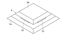
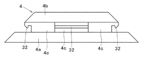
図3及び図4に示すように、側部材4は四角錐台状に形成されており、側部材4の四角錐台状の基部4a及び頭部4bの間には中間部4cが形成されている。
As shown in FIGS. 3 and 4, the
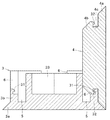
図5〜図13に示すように、例えば、上方の上下部材3及び隣接する2つの側部材4における六面体2の外部に面する外面側には、突出部7が設けられている。突出部7が設けられた上下部材3又は側部材4の内面側には、ボルト頭部穴8が設けられている。ボルト頭部穴8の底部には、ボルト頭部穴8から突出部7の先端部へ向かって貫通するようにボルト孔9が設けられている。突出部7の断面形状は、四角形状の他、三角形状、多角形状、円状、楕円状等でもよい。
As shown in FIGS. 5 to 13, for example, a
突出部7が設けられた上下部材3又は側部材4の外面側には、例えば断面形状がL字状の4つの補強用突出部10が設けられている。ここで、補強用突出部10の外周面に、長さ方向へ延びるリブ11を突設しておけば、補強用突出部10の強度向上を図ることができるという利点がある。補強用突出部10の数は、特に限定されるものではなく、3つ以下又は5つ以上でもよい。補強用突出部10の断面形状や位置も、必要に応じて適宜変更可能である。
On the outer surface side of the upper and
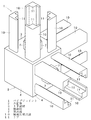
図14〜図16に示すように、突出部7が設けられた上下部材3又は側部材4に接合されるパイプ21の長さ方向の両端部には、それぞれ挿入穴22及び例えば4つの貫通孔23が設けられている。挿入穴22の下方には連結部24が設けられており、連結部24の下方には中空部25が設けられている。挿入穴22の底部には、雌ネジ穴26が設けられている。
As shown in FIGS. 14 to 16, at both end portions in the length direction of the
なお、連結部24の下方に中空部25を設けないで、連結部24をパイプ21の長さ方向へ延びるように形成してもよい。挿入穴22の断面形状は、上下部材3又は側部材4の突出部7の断面形状に合わせて形成しておけばよい。貫通孔23の断面形状は、上下部材3又は側部材4の補強用突出部10の断面形状に合わせて形成しておけばよい。貫通孔23の数も、特に限定されるものではなく、前記補強用突出部10の数に合わせて3つ以下又は5つ以上でもよい。パイプ21の断面形状や材質、挿入穴22の断面形状、貫通孔23の断面形状は、特に限定されるものではなく、従来公知の各種の構成を採用することができる。
The connecting
突出部7が設けられた上下部材3又は側部材4にパイプ21を接合するには、上下部材3又は側部材4の突出部7をパイプ21の挿入穴22に挿入し、上下部材3又は側部材4の補強用突出部10をパイプの貫通孔23に挿入し、ボルト27を上下部材3又は側部材4のボルト孔9に挿通し、ボルト27の頭部27aを上下部材3又は側部材4のボルト頭部穴8に挿入すると共に、ボルト27の雄ネジ部27bをパイプ21の雌ネジ穴26に螺入すればよい。なお、ボルト27の頭部27aの上面には、六角穴(図示せず)が設けられている。このように、突出部7が設けられた上下部材3又は側部材4の外面側に少なくとも1つの補強用突出部10を設けておけば、パイプ21をより強固に接合できるという利点がある。
To join the
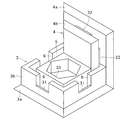
パイプジョイント1の組み立てに際しては、図5、図6、図12、及び図13に示すように、側部材4の中間部4cを上下部材3の切欠部6内に挿入し、側部材4の頭部4bを上下部材3の挿入溝5内に挿入し、側部材4の基部4aを上下部材3の基部3aに圧接し、側部材4の基部4a同士及び頭部4b同士を圧接し、2つの上下部材3の間に4つの側部材4を着脱自在に挟着することによって六面体2を形成すればよい。
When assembling the
なお、図12及び図13に示す例ではパイプ21を図示していないが、パイプジョイント1の組み立てが完了する前に、突出部7が設けられた上下部材3又は側部材4にパイプ21を接合しておけばよい。いずれにしても、2つの上下部材3及び4つの側部材4のうちの少なくとも1つとして、突出部7が設けられた上下部材3又は側部材4を適宜の位置に取り付ければ、パイプジョイント1に対して上方、下方、又は側方の1〜6方向にパイプ21を接合することができる。パイプジョイント1で適宜の方向にパイプ21を接合していけば、図14のようなラック28やシェルフ等を組み立てることができる。
12 and 13, the
ここで、図2〜図6、図12、及び図13に示すように、上下部材3の切欠部6の底部に係止爪31を突設し、側部材4の中間部4cの上端部及び下端部にそれぞれ係止爪32を突設し、側部材4の係止爪32を上下部材3の係止爪31に着脱自在に係止するように構成しておけば、上下部材3及び側部材4の互いの脱落を防止できるという利点がある。
Here, as shown in FIG. 2 to FIG. 6, FIG. 12, and FIG. 13, a locking
また、図3〜図5に示すように、側部材4の中間部4cの正面視形状を十字状に形成しておけば、側部材4を90度回転させた状態でも、側部材4の中間部4cを上下部材3の切欠部6に挿入できるので、側部材4の取付方向に特に注意を払わなくてもよいという利点がある。そして、側部材4の中間部4cの左端部及び右端部に係止爪32を突設しておけば、側部材4を90度回転させた状態でも、側部材4の係止爪32を上下部材3の係止爪31に着脱自在に係止できるという利点がある。
Further, as shown in FIGS. 3 to 5, if the
更に、図1及び図2に示すように、突出部7が設けられていない上下部材3の内面側にナット穴33を設けておけば、拡張パーツを固定するためのナットをナット穴33に収容できるので、突出部7が設けられていない上下部材3に拡張パーツを取り付けやすいという利点がある。また、図7〜図9に示すように、突出部7が設けられた上下部材3の内面側にナット穴33を設け、ボルト頭部穴8をナット穴33の底部に設けておけば、拡張パーツを固定するためのナットをナット穴33に収容できるので、突出部7が設けられた上下部材3に拡張パーツを取り付けやすいという利点がある。なお、上記のような拡張パーツとしては、キャスターや天井吊具等が挙げられる。
Further, as shown in FIGS. 1 and 2, if a
上記のように構成されたパイプジョイント1によれば、突出部7が設けられた上下部材3又は側部材4とパイプ21を接合するボルト27が露出しないので、見栄えが良いという利点がある。また、上下部材3又は側部材4の突出部7をパイプ21の挿入穴22に挿入した状態で、上下部材3又は側部材4とパイプ21をボルト27で接合できるので、パイプ21を強固に固定できるという利点がある。更に、パイプ21を接合しない場合には、突出部7が設けられていない上下部材3又は側部材4を取り付ければよいので、埃(ホコリ)がたまりにくいという利点がある。
According to the pipe joint 1 configured as described above, the
以上のように、本発明のパイプジョイントは、見栄えを良くし、パイプを強固に固定すると共に、パイプを接合しない場合には埃(ホコリ)をたまりにくくするためのパイプ接合手段として有用である。 INDUSTRIAL APPLICABILITY As described above, the pipe joint of the present invention is useful as a pipe joining means for improving the appearance, firmly fixing the pipe, and preventing dust (dust) from accumulating when the pipe is not joined.
1 パイプジョイント
2 六面体
3 上下部材
3a 基部
3b 本体部
4 側部材
4a 基部
4b 頭部
4c 中間部
5 挿入溝
6 切欠部
7 突出部
8 ボルト頭部穴
9 ボルト孔
10 補強用突出部
11 リブ
31 係止爪
32 係止爪
33 ナット穴
DESCRIPTION OF
Claims (8)
前記六面体の4つの側面部をそれぞれ構成する4つの側部材
を備え、
前記上下部材の基部を四角錐台状に形成し、
前記上下部材の本体部を四角形板状に形成し、
前記上下部材における前記六面体の内部空間に面する内面側に、周方向へ延びる平面視形状が四角形状の挿入溝を設け、
前記上下部材の挿入溝の外側方に4つの切欠部を周方向へ互いに間隔を開けて設け、
前記側部材を四角錐台状に形成し、
前記側部材の四角錐台状の基部及び頭部の間に中間部を形成し、
前記上下部材及び前記側部材のうちの少なくとも1つにおける前記六面体の外部に面する外面側に突出部を設け、
前記突出部が設けられた上下部材又は側部材の前記内面側にボルト頭部穴を設け、
前記ボルト頭部穴の底部に、前記ボルト頭部穴から前記突出部の先端部へ向かって貫通するようにボルト孔を設け、
前記側部材の中間部を前記上下部材の切欠部内に挿入し、
前記側部材の頭部を前記上下部材の挿入溝内に挿入し、
前記側部材の基部を前記上下部材の基部に圧接し、
前記側部材の基部同士及び頭部同士を圧接し、
前記2つの上下部材の間に前記4つの側部材を着脱自在に挟着することによって前記六面体を形成した
ことを特徴とするパイプジョイント。 Two upper and lower members respectively constituting the upper surface and the lower surface of the hexahedron;
Four side members respectively constituting the four side surfaces of the hexahedron,
The base of the upper and lower members is formed into a truncated pyramid shape,
The main body of the upper and lower members is formed in a rectangular plate shape,
On the inner surface of the upper and lower members facing the inner space of the hexahedron, an insertion groove having a quadrangular shape in a plan view extending in the circumferential direction is provided,
Four notches are provided on the outer side of the insertion groove of the upper and lower members at intervals in the circumferential direction,
The side member is formed into a truncated pyramid shape,
An intermediate portion is formed between the base and the head of the truncated pyramid of the side member,
The projecting portion is provided on the outer surface facing the outside of the hexahedron in at least one of said upper and lower members and said side members,
The bolt head hole provided in the inner surface of the upper and lower members or side member said projecting portion is provided,
At the bottom of the bolt head hole, a bolt hole is provided so as to penetrate from the bolt head hole toward the tip of the protrusion,
Insert the middle portion of the side member into the notch of the upper and lower members,
Insert the head of the side member into the insertion groove of the upper and lower members,
Pressing the base of the side member to the base of the upper and lower members,
The base parts of the side members and the head parts are pressed together,
The pipe joint characterized in that the hexahedron is formed by detachably sandwiching the four side members between the two upper and lower members.
前記側部材の中間部の上端部及び下端部にそれぞれ係止爪を突設し、
前記側部材の係止爪を前記上下部材の係止爪に着脱自在に係止した
請求項1に記載のパイプジョイント。 Providing a locking claw on the bottom of the notch of the upper and lower members,
Locking claws are provided on the upper end and the lower end of the middle part of the side member,
The pipe joint according to claim 1, wherein the engaging claws of the side members are detachably engaged with the engaging claws of the upper and lower members.
前記側部材の中間部の左端部及び右端部に係止爪を突設した
請求項2に記載のパイプジョイント。 Forming a cross shape in a front view of the intermediate portion of the side member,
The pipe joint according to claim 2, wherein locking claws are provided so as to project from a left end portion and a right end portion of an intermediate portion of the side member.
前記ボルト頭部穴を前記ナット穴の底部に設けた
請求項1から7のいずれかに記載のパイプジョイント。 The nut holes provided in the inner surface of the vertical member to which the protruding portion is provided,
The pipe joint according to claim 1, wherein the bolt head hole is provided at the bottom of the nut hole.
Priority Applications (1)
| Application Number | Priority Date | Filing Date | Title |
|---|---|---|---|
| JP2017178444A JP6749572B2 (en) | 2017-09-18 | 2017-09-18 | Pipe joint |
Applications Claiming Priority (1)
| Application Number | Priority Date | Filing Date | Title |
|---|---|---|---|
| JP2017178444A JP6749572B2 (en) | 2017-09-18 | 2017-09-18 | Pipe joint |
Publications (2)
| Publication Number | Publication Date |
|---|---|
| JP2019052737A JP2019052737A (en) | 2019-04-04 |
| JP6749572B2 true JP6749572B2 (en) | 2020-09-02 |
Family
ID=66013634
Family Applications (1)
| Application Number | Title | Priority Date | Filing Date |
|---|---|---|---|
| JP2017178444A Active JP6749572B2 (en) | 2017-09-18 | 2017-09-18 | Pipe joint |
Country Status (1)
| Country | Link |
|---|---|
| JP (1) | JP6749572B2 (en) |
Families Citing this family (2)
| Publication number | Priority date | Publication date | Assignee | Title |
|---|---|---|---|---|
| JP2021032378A (en) * | 2019-08-28 | 2021-03-01 | 株式会社Coba | Joint member |
| JP2022057233A (en) * | 2020-09-30 | 2022-04-11 | 有限会社イマジン | Frame joint and frame rack therefor |
Family Cites Families (2)
| Publication number | Priority date | Publication date | Assignee | Title |
|---|---|---|---|---|
| JPS5234805Y2 (en) * | 1971-12-20 | 1977-08-09 | ||
| JPS5067269U (en) * | 1973-10-22 | 1975-06-16 |
-
2017
- 2017-09-18 JP JP2017178444A patent/JP6749572B2/en active Active
Also Published As
| Publication number | Publication date |
|---|---|
| JP2019052737A (en) | 2019-04-04 |
Similar Documents
| Publication | Publication Date | Title |
|---|---|---|
| US9121433B1 (en) | Joining elements for channelled structural members | |
| JP6749572B2 (en) | Pipe joint | |
| US20080000857A1 (en) | Modular organizer for crib or playpen | |
| JP2015007365A (en) | Mounting structure for louver panel for construction | |
| KR101507387B1 (en) | mounting structure for three members | |
| JP2011503456A (en) | Connection fixture and mounting configuration | |
| KR100645323B1 (en) | The connection structure of a fml type lamp and socket | |
| KR101458767B1 (en) | A clip for floor panel | |
| JP3104160U (en) | Storage shelf structure | |
| JP6867708B2 (en) | Sheet covering structure | |
| JP3209776U (en) | Combination floorboard | |
| KR101514888B1 (en) | A bracket for absorbing tolerance | |
| JP2006322180A (en) | Window frame body | |
| JP2003339478A (en) | Bed device | |
| JP6687688B2 (en) | Mounting member for louver material | |
| KR200484266Y1 (en) | Clip | |
| JP2010222954A (en) | Lattice body | |
| JP4436798B2 (en) | Mounting bracket for ALC down wall bottom drain | |
| JP2008024384A (en) | Elevator cage | |
| JP6750204B2 (en) | table | |
| JP2007120047A (en) | Projected corner accessory constituting body for installing exterior panel | |
| JP6914060B2 (en) | Partition wall fittings and connection structures | |
| JP2020000701A (en) | Assembly bracket for bed | |
| KR20100086737A (en) | Cable tray | |
| KR102107681B1 (en) | Double thread bolt, nut and snapring nut |
Legal Events
| Date | Code | Title | Description |
|---|---|---|---|
| A621 | Written request for application examination |
Free format text: JAPANESE INTERMEDIATE CODE: A621 Effective date: 20190408 |
|
| A977 | Report on retrieval |
Free format text: JAPANESE INTERMEDIATE CODE: A971007 Effective date: 20200116 |
|
| A131 | Notification of reasons for refusal |
Free format text: JAPANESE INTERMEDIATE CODE: A131 Effective date: 20200129 |
|
| A521 | Request for written amendment filed |
Free format text: JAPANESE INTERMEDIATE CODE: A523 Effective date: 20200309 |
|
| TRDD | Decision of grant or rejection written | ||
| A01 | Written decision to grant a patent or to grant a registration (utility model) |
Free format text: JAPANESE INTERMEDIATE CODE: A01 Effective date: 20200715 |
|
| A61 | First payment of annual fees (during grant procedure) |
Free format text: JAPANESE INTERMEDIATE CODE: A61 Effective date: 20200716 |
|
| R150 | Certificate of patent or registration of utility model |
Ref document number: 6749572 Country of ref document: JP Free format text: JAPANESE INTERMEDIATE CODE: R150 |
|
| R250 | Receipt of annual fees |
Free format text: JAPANESE INTERMEDIATE CODE: R250 |