JP6749480B2 - System, method and non-transitory computer readable storage medium for parking a vehicle - Google Patents
System, method and non-transitory computer readable storage medium for parking a vehicle Download PDFInfo
- Publication number
- JP6749480B2 JP6749480B2 JP2019512321A JP2019512321A JP6749480B2 JP 6749480 B2 JP6749480 B2 JP 6749480B2 JP 2019512321 A JP2019512321 A JP 2019512321A JP 2019512321 A JP2019512321 A JP 2019512321A JP 6749480 B2 JP6749480 B2 JP 6749480B2
- Authority
- JP
- Japan
- Prior art keywords
- vehicle
- kinematic
- state
- node
- initial
- Prior art date
- Legal status (The legal status is an assumption and is not a legal conclusion. Google has not performed a legal analysis and makes no representation as to the accuracy of the status listed.)
- Active
Links
Images


Classifications
-
- B—PERFORMING OPERATIONS; TRANSPORTING
- B60—VEHICLES IN GENERAL
- B60W—CONJOINT CONTROL OF VEHICLE SUB-UNITS OF DIFFERENT TYPE OR DIFFERENT FUNCTION; CONTROL SYSTEMS SPECIALLY ADAPTED FOR HYBRID VEHICLES; ROAD VEHICLE DRIVE CONTROL SYSTEMS FOR PURPOSES NOT RELATED TO THE CONTROL OF A PARTICULAR SUB-UNIT
- B60W30/00—Purposes of road vehicle drive control systems not related to the control of a particular sub-unit, e.g. of systems using conjoint control of vehicle sub-units, or advanced driver assistance systems for ensuring comfort, stability and safety or drive control systems for propelling or retarding the vehicle
- B60W30/08—Active safety systems predicting or avoiding probable or impending collision or attempting to minimise its consequences
- B60W30/095—Predicting travel path or likelihood of collision
- B60W30/0953—Predicting travel path or likelihood of collision the prediction being responsive to vehicle dynamic parameters
-
- B—PERFORMING OPERATIONS; TRANSPORTING
- B60—VEHICLES IN GENERAL
- B60W—CONJOINT CONTROL OF VEHICLE SUB-UNITS OF DIFFERENT TYPE OR DIFFERENT FUNCTION; CONTROL SYSTEMS SPECIALLY ADAPTED FOR HYBRID VEHICLES; ROAD VEHICLE DRIVE CONTROL SYSTEMS FOR PURPOSES NOT RELATED TO THE CONTROL OF A PARTICULAR SUB-UNIT
- B60W30/00—Purposes of road vehicle drive control systems not related to the control of a particular sub-unit, e.g. of systems using conjoint control of vehicle sub-units, or advanced driver assistance systems for ensuring comfort, stability and safety or drive control systems for propelling or retarding the vehicle
- B60W30/06—Automatic manoeuvring for parking
-
- B—PERFORMING OPERATIONS; TRANSPORTING
- B60—VEHICLES IN GENERAL
- B60W—CONJOINT CONTROL OF VEHICLE SUB-UNITS OF DIFFERENT TYPE OR DIFFERENT FUNCTION; CONTROL SYSTEMS SPECIALLY ADAPTED FOR HYBRID VEHICLES; ROAD VEHICLE DRIVE CONTROL SYSTEMS FOR PURPOSES NOT RELATED TO THE CONTROL OF A PARTICULAR SUB-UNIT
- B60W30/00—Purposes of road vehicle drive control systems not related to the control of a particular sub-unit, e.g. of systems using conjoint control of vehicle sub-units, or advanced driver assistance systems for ensuring comfort, stability and safety or drive control systems for propelling or retarding the vehicle
- B60W30/08—Active safety systems predicting or avoiding probable or impending collision or attempting to minimise its consequences
- B60W30/095—Predicting travel path or likelihood of collision
- B60W30/0956—Predicting travel path or likelihood of collision the prediction being responsive to traffic or environmental parameters
-
- B—PERFORMING OPERATIONS; TRANSPORTING
- B62—LAND VEHICLES FOR TRAVELLING OTHERWISE THAN ON RAILS
- B62D—MOTOR VEHICLES; TRAILERS
- B62D15/00—Steering not otherwise provided for
- B62D15/02—Steering position indicators ; Steering position determination; Steering aids
- B62D15/027—Parking aids, e.g. instruction means
- B62D15/0285—Parking performed automatically
-
- B—PERFORMING OPERATIONS; TRANSPORTING
- B60—VEHICLES IN GENERAL
- B60W—CONJOINT CONTROL OF VEHICLE SUB-UNITS OF DIFFERENT TYPE OR DIFFERENT FUNCTION; CONTROL SYSTEMS SPECIALLY ADAPTED FOR HYBRID VEHICLES; ROAD VEHICLE DRIVE CONTROL SYSTEMS FOR PURPOSES NOT RELATED TO THE CONTROL OF A PARTICULAR SUB-UNIT
- B60W50/00—Details of control systems for road vehicle drive control not related to the control of a particular sub-unit, e.g. process diagnostic or vehicle driver interfaces
- B60W2050/0001—Details of the control system
- B60W2050/0019—Control system elements or transfer functions
- B60W2050/0028—Mathematical models, e.g. for simulation
- B60W2050/0031—Mathematical model of the vehicle
-
- B—PERFORMING OPERATIONS; TRANSPORTING
- B60—VEHICLES IN GENERAL
- B60W—CONJOINT CONTROL OF VEHICLE SUB-UNITS OF DIFFERENT TYPE OR DIFFERENT FUNCTION; CONTROL SYSTEMS SPECIALLY ADAPTED FOR HYBRID VEHICLES; ROAD VEHICLE DRIVE CONTROL SYSTEMS FOR PURPOSES NOT RELATED TO THE CONTROL OF A PARTICULAR SUB-UNIT
- B60W2510/00—Input parameters relating to a particular sub-units
- B60W2510/20—Steering systems
- B60W2510/207—Oversteer or understeer
-
- B—PERFORMING OPERATIONS; TRANSPORTING
- B60—VEHICLES IN GENERAL
- B60W—CONJOINT CONTROL OF VEHICLE SUB-UNITS OF DIFFERENT TYPE OR DIFFERENT FUNCTION; CONTROL SYSTEMS SPECIALLY ADAPTED FOR HYBRID VEHICLES; ROAD VEHICLE DRIVE CONTROL SYSTEMS FOR PURPOSES NOT RELATED TO THE CONTROL OF A PARTICULAR SUB-UNIT
- B60W2530/00—Input parameters relating to vehicle conditions or values, not covered by groups B60W2510/00 or B60W2520/00
- B60W2530/201—Dimensions of vehicle
-
- B—PERFORMING OPERATIONS; TRANSPORTING
- B60—VEHICLES IN GENERAL
- B60W—CONJOINT CONTROL OF VEHICLE SUB-UNITS OF DIFFERENT TYPE OR DIFFERENT FUNCTION; CONTROL SYSTEMS SPECIALLY ADAPTED FOR HYBRID VEHICLES; ROAD VEHICLE DRIVE CONTROL SYSTEMS FOR PURPOSES NOT RELATED TO THE CONTROL OF A PARTICULAR SUB-UNIT
- B60W2554/00—Input parameters relating to objects
-
- B—PERFORMING OPERATIONS; TRANSPORTING
- B60—VEHICLES IN GENERAL
- B60W—CONJOINT CONTROL OF VEHICLE SUB-UNITS OF DIFFERENT TYPE OR DIFFERENT FUNCTION; CONTROL SYSTEMS SPECIALLY ADAPTED FOR HYBRID VEHICLES; ROAD VEHICLE DRIVE CONTROL SYSTEMS FOR PURPOSES NOT RELATED TO THE CONTROL OF A PARTICULAR SUB-UNIT
- B60W2710/00—Output or target parameters relating to a particular sub-units
- B60W2710/20—Steering systems
-
- G—PHYSICS
- G06—COMPUTING; CALCULATING OR COUNTING
- G06N—COMPUTING ARRANGEMENTS BASED ON SPECIFIC COMPUTATIONAL MODELS
- G06N5/00—Computing arrangements using knowledge-based models
- G06N5/01—Dynamic search techniques; Heuristics; Dynamic trees; Branch-and-bound
Description
本発明は、包括的には、車両の経路計画に関し、より詳細には、車両を目標空間に自動的に駐車する経路計画方法に関する。 The present invention relates generally to vehicle route planning, and more particularly to a route planning method for automatically parking a vehicle in a target space.
自律車両又は自律走行モードを実行する車両のいずれかの車両によって利用されるいくつかの制御システムは、他の車両又は歩行者等の障害物を回避するためのみではなく、車両の操作に関連付けられたいくつかの基準を最適化するためも含む双方で、未来を予測し、車両の安全運動又は経路を予測する。目標状態は、固定ロケーション、移動ロケーション、速度ベクトル、領域、又はそれらの組み合わせのいずれかとすることができる。道路縁、歩行者、及び他の車両等の周囲環境は、車両のセンサーによって検知される、及び/又は、事前に与えられた情報によって少なくとも部分的に既知である。 Some control systems utilized by a vehicle, either an autonomous vehicle or a vehicle executing an autonomous driving mode, are associated not only with avoiding obstacles such as other vehicles or pedestrians, but also with the operation of the vehicle. Predicting the future and predicting the safe movement or path of the vehicle, both including to optimize some criteria. The target state can be either a fixed location, a moving location, a velocity vector, a region, or a combination thereof. The surrounding environment, such as road edges, pedestrians, and other vehicles, is at least partially known by the vehicle's sensors and/or pre-given information.
自律運転モードにおいて実行される自律車両又は半自律車両を制御するタスクのうちの1つは、車両を、本明細書において目標状態と称される駐車位置及び駐車方位に自動的に駐車することである。駐車タスクは、以下のように定式化することができる。車両動態、駐車空間のマップ、車両の開始位置及び開始方位を表す初期状態、並びに車両の目標駐車位置及び目標駐車方位を表す目標状態が与えられると、車両の初期状態から目標状態への所望の経路又は運動を求め、次いで、車両のアクチュエーター、例えば車両のガスペダル及びハンドルを制御して、車両が所望の経路又は運動を辿ることを確実にする。しかしながら、車両の運動についての非ホロノミック制約及び駐車施設又は駐車場等の駐車空間における一般的に狭小な自由空間に起因して、車両を自動的に駐車する経路計画は、困難を有する。 One of the tasks of controlling an autonomous or semi-autonomous vehicle performed in autonomous driving mode is to automatically park the vehicle in a parking position and orientation, referred to herein as a target state. is there. The parking task can be formulated as follows. Given the vehicle dynamics, the map of the parking space, the initial state indicating the starting position and the starting direction of the vehicle, and the target state indicating the target parking position and the target parking direction of the vehicle, the desired state from the initial state of the vehicle to the target state is obtained. The path or movement is determined and then the vehicle's actuators, such as the vehicle's gas pedal and steering wheel, are controlled to ensure that the vehicle follows the desired path or movement. However, due to the non-holonomic constraints on vehicle motion and the generally narrow free space in parking spaces such as parking facilities or parking lots, route planning for automatically parking vehicles has difficulties.
大半の既存の経路計画解決法は、特定の駐車シナリオに対処するか、又は駐車空間の特定のジオメトリを想定するのみである。例えば、特許文献1に記載の方法は、縦列駐車及び後方駐車の経路を計算する。特許文献2に記載の方法は、駐車経路の特別の構造を想定し、障害物を無視し、駐車空間の特定のジオメトリに基づいて経路を計算する。また、特許文献3に記載の方法は、縦列駐車に対処し、車両の初期状態が、事前にコード化された縦列駐車操作が開始されるいわゆる実現可能開始領域内にあることを必要とする。上述の方法は、リアルタイム経路生成を達成するが、多かれ少なかれ、障害物のタイプ、駐車空間のジオメトリ、及び駐車タスクを制限しており、全般的な駐車シナリオを考慮することができない。
Most existing route planning solutions either address specific parking scenarios or only assume a specific geometry of the parking space. For example, the method described in
したがって、実生活における多様な駐車シナリオに適した、車両を目標空間に自動的に駐車するシステム及び方法が必要とされている。 Therefore, there is a need for a system and method for automatically parking a vehicle in a target space that is suitable for a variety of real life parking scenarios.
いくつかの実施形態の目的は、車両の自動化駐車システム及び方法のためのリアルタイム経路生成を可能にする経路計画方法を開示することである。いくつかの実施形態の別の目的は、実生活の狭小な駐車空間における多様な駐車シナリオについての自動駐車の具体例によって引き起こされる経路計画の計算コストを低減するような方法を提供することである。 The purpose of some embodiments is to disclose a route planning method that enables real-time route generation for an automated vehicle parking system and method. Another object of some embodiments is to provide such a method that reduces the computational cost of route planning caused by the example of automatic parking for a variety of parking scenarios in real life small parking spaces. ..
いくつかの実施形態は、任意のレイアウトを有する駐車空間を通じて所望の経路を発見するのに、サンプリングに基づく経路計画方法を用いることができるという理解に基づいている。一方で、いくつかの実施形態は、高速探索ランダムツリー(RRT:rapid−exploring random tree)方法及びその変形等のサンプリングに基づく経路計画方法を、自動化駐車問題に適用する結果として、このタスクを計算上非実用的にする複数の無駄な計算がもたらされる可能性があるという認識に基づいている。一般的な駐車シナリオにおいて、駐車スポットは、車両の初期位置、例えば現在位置から比較的離れて位置する。加えて、駐車施設又は駐車場の空間等の駐車空間の狭小な自由空間及び複雑なマップに起因して、駐車スポットへの経路は、異なる形式及び形状を有する可能性がある。そのために、そのような経路を発見する目的で、経路の実現可能性について、駐車空間全体をサンプリングしてテストする必要があり得る。結果として、サンプリングに基づく経路計画方法の単純な適用により、全ての未探索状態空間が不必要にサンプリングされ、リアルタイム駐車応用の非実用的な解がもたらされる可能性がある。 Some embodiments are based on the understanding that a sampling-based route planning method can be used to find a desired route through a parking space having an arbitrary layout. On the other hand, some embodiments compute this task as a result of applying a sampling-based path planning method such as a rapid-exploring random tree (RRT) method and its variants to the automated parking problem. It is based on the recognition that it can lead to multiple useless calculations that make it impractical. In a typical parking scenario, the parking spot is located relatively far from the initial position of the vehicle, eg the current position. In addition, due to the narrow free space and complex maps of parking spaces such as parking facilities or parking spaces, the routes to parking spots can have different forms and shapes. To that end, it may be necessary to sample and test the entire parking space for the feasibility of the route in order to discover such routes. As a result, a simple application of the sampling-based path planning method may unnecessarily sample all unsearched state spaces, resulting in impractical solutions for real-time parking applications.
いくつかの実施形態は、駐車問題を、少なくとも2つのステージを用いて解くことができるという認識に基づいている。第1のステージにおいて、車両の初期状態を目標状態と接続する運動学的経路(kinematic path)が構築される。第2のステージにおいて、この運動学的経路を辿る実際の軌道が求められる。運動学的経路は、車両の動的モデルよりも単純である運動学的モデルを用いて構築することができるので、このような手法は有利である。 Some embodiments are based on the recognition that parking problems can be solved using at least two stages. In the first stage, a kinematic path connecting the initial state of the vehicle with the target state is established. In the second stage, the actual trajectory following this kinematic path is determined. Such an approach is advantageous because the kinematic path can be constructed using a kinematic model that is simpler than the dynamic model of the vehicle.
2ステージ問題分割により、当初の駐車問題を以下のものに再定式化することができる。車両のジオメトリ、駐車空間のマップ、及び車両の運動学的モデルが与えられると、本明細書において運動学的経路と称される、初期状態を目標状態に接続する、実現可能でありかつ衝突を伴わない(collision free)経路を発見する。運動学的な実現可能性は、運動学的経路が初期状態をその初期値とする車両運動学の解であり、したがって、この運動学的経路を、車両が初期状態から開始して辿ることができることを確実にする。衝突を伴わないという特性は、車両が、運動学的経路に沿って運動する間、駐車空間において障害物と衝突しないことを保証する。 By dividing the two-stage problem, the original parking problem can be reformulated into the following. Given the geometry of the vehicle, the map of the parking space, and the kinematic model of the vehicle, which is referred to herein as the kinematic path, connecting the initial state to the target state, a feasible and collision-free Find a collision free route. Kinematic feasibility is the solution of vehicle kinematics whose initial value is the kinematic path, so that this kinematic path is not traversable starting from the initial state of the vehicle. Make sure you can. The collision-free property guarantees that the vehicle does not collide with obstacles in the parking space while moving along the kinematic path.
運動学的モデルが通常、車両の動的モデルよりも単純であるにもかかわらず、運動学的経路の運動学的実現可能性について駐車空間全体をサンプリングしてテストする必要がある場合、自動化駐車問題の解は、依然として計算上非実用的である可能性がある。高速道路を走行する車両についての経路計画と比較して、車両の自動化駐車システムの経路計画は、固有の特性を有する。すなわち、環境内の衝突を伴わない空間は、通常、非常に狭小であり、サンプリングに基づく方法が遥かに低速で駐車空間を探索することが必要とされる。結果として、衝突を伴わない空間を通じて2つの状態を接続する運動学的経路を構築することは、より困難である。 If the kinematic model is usually simpler than the dynamic model of the vehicle, but the entire parking space needs to be sampled and tested for kinematic feasibility of the kinematic path, automated parking The solution to the problem may still be computationally impractical. Compared with route planning for vehicles traveling on highways, route planning for automated vehicle parking systems has unique characteristics. That is, the collision-free space in the environment is usually very small, requiring a sampling-based method to search the parking space much slower. As a result, it is more difficult to build a kinematic path that connects two states through a collision-free space.
加えて、いくつかの実施形態は、駐車空間全体のサンプリング問題を、計画の部分問題のセットに分割することができるという全体的な理解に基づいている。例えば、初期状態及び目標状態の双方からの運動学的グラフの構築を開始すること、及び/又は、駐車空間を部分空間のセットに分割することが可能である。一方で、ランダム分割は、計算効率を高めない場合があり、断片的な及び/又は実現不可能な運動学的経路をもたらす場合がある。 In addition, some embodiments are based on the overall understanding that the sampling problem for the entire parking space can be divided into a set of sub-problems for the plan. For example, it is possible to start building kinematic graphs from both initial and target states and/or divide the parking space into sets of subspaces. On the other hand, random partitioning may not be computationally efficient and may result in fractional and/or infeasible kinematic paths.
いくつかの実施形態は、各部分問題の解を接続して、初期状態と目標状態とを接続する実現可能な運動学的経路を求めることができるように、駐車空間問題のサンプリングを部分問題のセットに分割する必要があるという認識に基づいている。加えて、部分問題のセットへの分割は、駐車空間の分割状態をサンプリングする方法についての指針を提供するべきである。これは、一般的なサンプリング問題において、サンプリングされた状態は、初期状態と目標状態との間の比較的大きな距離に起因して、駐車空間において構築される運動学的ツリーの近くにあり、このツリーに追加される確率が低いためである。この低い確率は、運動学的ツリーへの近接性を求めるために行われる計算が無駄になる可能性の方が高いことを意味する。近接性の検出における計算の無駄を回避するために、サンプリングされた状態は、双方のツリーから離れているものの、運動学的ツリーの近傍として扱うことができる。一方で、そのように扱うことで、衝突検出ステージにおいて無駄な計算が増加する。これは、距離のあるサンプリングされた状態を、運動学的ツリーへの近傍として扱う場合、サンプリングされた状態と運動学的ツリーとの間の衝突を伴わない接続を有する確率が低いためである。低確率イベントを検出するのに適用されるいずれの計算も、無駄になる可能性が最も高く、したがって、低計算効率を招く。 Some embodiments sample the parking space problem into sub-problems so that the solutions of each sub-problem can be connected to determine a feasible kinematic path connecting the initial and target states. It is based on the recognition that it needs to be divided into sets. In addition, the partitioning into sub-problems should provide guidance on how to sample the partitioning state of the parking space. This is because in a typical sampling problem the sampled states are close to the kinematic tree constructed in the parking space due to the relatively large distance between the initial state and the target state, This is because the probability of being added to the tree is low. This low probability means that the calculations performed to find the proximity to the kinematic tree are more likely to be wasted. To avoid wasting computation in proximity detection, the sampled states can be treated as a neighborhood of the kinematic tree, although they are far from both trees. On the other hand, such treatment increases unnecessary calculation in the collision detection stage. This is because treating a sampled state with a distance as a neighborhood to the kinematic tree is less likely to have a collision-free connection between the sampled state and the kinematic tree. Any calculations applied to detect low probability events are most likely to be wasted, thus leading to low computational efficiency.
いくつかの実施形態は、車両の初期状態を、通過点のセットを通じて駐車車両の目標状態と接続する衝突を伴わない幾何学的経路(geometric path)を用いて、運動学的経路を構築するためにサンプリング問題を部分問題のセットに分割することができ、それにより、サンプリングの計算効率を高めるとともに実現可能な運動学的経路を提供することができるという理解に基づいている。 Some embodiments are for constructing a kinematic path using a collision-free geometric path that connects the initial state of the vehicle with the target state of the parked vehicle through a set of transit points. It is based on the understanding that the sampling problem can be divided into a set of subproblems, which can increase the computational efficiency of sampling and provide a feasible kinematic path.
幾何学的経路は、車両のジオメトリ及び駐車空間のマップのみを用いて、すなわち、車両の運動学的モデル又は動的モデルを考慮することなく構築することができる。このようにして、幾何学的経路の計算が単純化される。幾何学的経路の衝突を伴わないという特性は、衝突を伴わない運動学的経路を幾何学的経路から開始して構築することができる可能性を高める。加えて、各通過点が車両の位置及び方位を規定する通過点の対は、サンプリング問題の有利な分割を提供する。 The geometric path can be constructed using only the map of the vehicle's geometry and the parking space, ie without considering the kinematic or dynamic model of the vehicle. In this way the calculation of the geometrical path is simplified. The collision-free property of geometric paths increases the possibility that collision-free kinematic paths can be constructed starting from geometric paths. In addition, the pairs of passing points, where each passing point defines the position and orientation of the vehicle, provide an advantageous division of the sampling problem.
具体的には、車両の運動学的モデルを用いて、近傍の通過点の各対を接続する運動学的サブグラフのセットを求めて運動学的グラフを形成することができる。例えば、1つの実施形態において、2つの隣接した通過点が、例えば、一本の線の直線線分又は異なる幾何学的形状を用いて接続される。そのような場合、各部分問題は、「2つの隣接した通過点を接続する運動学的経路を発見する」こととして定式化することができる。全ての部分問題を解くことができる場合、初期状態は、運動学的経路を通じて目標状態に接続することができる。これは、当初の経路計画問題が解かれることを更に暗示する。 Specifically, a kinematic model of a vehicle can be used to form a kinematic graph by finding a set of kinematic subgraphs that connect each pair of nearby transit points. For example, in one embodiment, two adjacent transit points are connected using, for example, a straight line segment of a line or different geometric shapes. In such cases, each subproblem can be formulated as "finding a kinematic path connecting two adjacent transit points". If all subproblems can be solved, the initial state can be connected to the target state through a kinematic path. This further implies that the original path planning problem is solved.
とりわけ、近傍の通過点は、通常、互いの方が車両の初期状態及び目標状態よりも近くにあるので、駐車空間のバイアスサンプリングを用いて各運動学的サブグラフを構築することができる。そのために、状態の各新たなサンプルは、運動学的サブツリーのうちの1つに追加される可能性の方が高く、したがって、計算の無駄を低減する。 Notably, since the nearby pass points are typically closer to each other than the vehicle's initial and target states, parking space bias sampling can be used to construct each kinematic subgraph. As such, each new sample of states is more likely to be added to one of the kinematic subtrees, thus reducing computational waste.
1つの実施形態において、部分問題は、逐次的に解かれる。例えば、部分問題1は、「初期ノードと第2の通過点に対応するノードとを接続する運動学的サブグラフSG1を発見する」こととして構築され、部分問題2は、「運動学的サブグラフSG1を第3の通過点と接続する運動学的サブグラフSG2を発見する」こととして構築され、最終的に、最後の部分問題は、「最後から1つ前の運動学的サブグラフを最後の通過点と接続する運動学的グラフを発見する」こととして構築される。別の実施形態において、部分問題は並列的に解かれ、したがって、計算速度を桁違いに高速化する。並列的に解かれる部分問題は、逐次的に解かれる部分問題と異なるものとすることができる。
In one embodiment, the subproblems are solved sequentially. For example,
1つの実施形態は、バイアスされたサンプリングを用いて、運動学的グラフを構築するために状態サンプリングを導く。付加的又は代替的に、1つの実施形態は、近似的な到達可能セットをサンプリングステップに用いて、サンプリングされた状態の品質を改善する。近似的な到達可能セットを考慮に入れることによって、接続するのが困難であるか又はコストがかかるサンプリングされた状態は、拒絶される。この処理は、非効率なサンプルに起因した衝突検出における計算時間の無駄を低減することができ、また、運動学的グラフの高速な構築を可能にする通過点のセットを提供することができる。 One embodiment uses biased sampling to derive state sampling to build a kinematic graph. Additionally or alternatively, one embodiment uses an approximate reachable set for the sampling step to improve the quality of the sampled state. By taking into account the approximate reachable set, sampled states that are difficult or costly to connect are rejected. This process can reduce the computation time wastage in collision detection due to inefficient samples, and can also provide a set of transit points that allows fast construction of kinematic graphs.
したがって、1つの実施形態は、車両を駐車空間内に駐車する方法であって、方法は、車両のジオメトリ、駐車空間のマップ、車両の運動学的モデル、及び車両の動的モデルを記憶するメモリに結合されたプロセッサを使用し、プロセッサは、方法を実施する記憶命令に結合され、記憶命令は、プロセッサによって実行されると、方法の少なくともいくつかのステップを実行し、少なくともいくつかのステップは、
車両のジオメトリ及び駐車空間のマップを用いて、車両の初期状態を、通過点のセットを通じて駐車車両の目標状態と接続する衝突を伴わない幾何学的経路を求めることであって、各通過点は、車両の位置及び方位を規定することと、
車両の運動学的モデルを用いて、運動学的エッジと接続された複数のノードを有する運動学的グラフを形成する運動学的サブグラフのセットを求めることであって、各運動学的サブグラフは、幾何学的経路の近傍の通過点の対を接続し、各ノードは、車両の状態を規定し、2つのノードを接続する各運動学的エッジは、車両の運動学的特性に従って2つのノードを接続する衝突を伴わない運動学的経路を規定することと、
運動学的グラフから、車両の初期状態に対応する初期ノードを、中間ノードのセットを通じて、車両の目標状態に対応する目標ノードと接続する運動学的経路を選択することと、
車両の動的モデルを用いて、運動学的経路を時間の関数として追跡する基準軌道を求めることと、
基準軌道に従って車両の運動を制御することと、
を含み、
幾何学的経路を求めることは、
初期ノードを、衝突を伴わないノードのセットを通じて目標ノードと接続する幾何学的グラフを構築することであって、幾何学的グラフにおけるノードの各対は、車両及び駐車空間のジオメトリのみを用いて求められた衝突を伴わないエッジで接続されることと、
幾何学的経路の通過点のセットを形成する幾何学的グラフからノードのセットを選択することと、
を含み、
駐車空間の状態空間内の点をサンプリングして、サンプリングされた状態を生成することと、
幾何学的グラフのノードの全ての状態がサンプリングされた状態の到達不可能エリア内にある場合、サンプリングされた状態を拒絶することと、
そうではない場合、
サンプリングされた状態に最も近い状態を有する幾何学的グラフの最近傍のノードを求めることと、
サンプリングされた状態のノードを幾何学的グラフに追加すること、及び追加されたノードを、エッジが衝突を伴わない場合にエッジを介して最近傍のノードと接続することと、
サンプリングすること、拒絶すること、求めること、及び追加することを、初期ノードが目標ノードに接続されるまで繰り返すことと、
を更に含む、方法を開示する。
Accordingly, one embodiment is a method of parking a vehicle in a parking space, the method comprising a memory that stores a geometry of the vehicle, a map of the parking space, a kinematic model of the vehicle, and a dynamic model of the vehicle. using a processor coupled to the processor, it is coupled to storage instructions implementing the method, storage instructions, when executed by a processor, perform at least some steps of the method, at least some of the steps ,
Using a map of the vehicle's geometry and parking space to determine a collision-free geometric path connecting the initial state of the vehicle to the target state of the parked vehicle through a set of passing points, each passing point being , Defining the position and orientation of the vehicle,
Determining a set of kinematic subgraphs forming a kinematic graph having a plurality of nodes connected to kinematic edges using a kinematic model of a vehicle, each kinematic subgraph being Each node connects a pair of passing points in the vicinity of a geometrical path, each node defines the state of the vehicle, and each kinematic edge connecting the two nodes connects two nodes according to the kinematic characteristics of the vehicle. Defining a kinematic path without connecting collisions,
Selecting a kinematic path connecting from the kinematic graph an initial node corresponding to the initial state of the vehicle through a set of intermediate nodes with a target node corresponding to the target state of the vehicle;
Determining a reference trajectory that tracks a kinematic path as a function of time using a dynamic vehicle model;
Controlling the movement of the vehicle according to a reference trajectory,
Only including,
Finding a geometric path is
Constructing a geometric graph connecting an initial node to a target node through a set of nodes without collision, each pair of nodes in the geometric graph using only the geometry of the vehicle and the parking space. Connected at the edges without the required collision,
Selecting a set of nodes from a geometric graph forming a set of transit points of the geometric path;
Including,
Sampling points in the state space of the parking space to produce sampled states;
Rejecting the sampled state if all states of the nodes of the geometric graph are within the unreachable area of the sampled state, and
If not,
Finding the nearest node of the geometric graph having the state closest to the sampled state,
Adding the sampled state node to the geometric graph, and connecting the added node with the nearest node via the edge if the edge does not involve a collision;
Repeating sampling, rejecting, seeking, and adding until the initial node is connected to the target node;
Further disclosed including a method.
別の実施形態は、車両を駐車空間内に駐車するシステムであって、
車両のジオメトリ、駐車空間のマップ、車両の運動学的モデル、及び車両の動的モデルを記憶するメモリと、
メモリに結合されたプロセッサであって、
車両のジオメトリ及び駐車空間のマップを用いて、車両の初期状態を、通過点のセットを通じて駐車車両の目標状態と接続する衝突を伴わない幾何学的経路を求めることであって、各通過点は、車両の位置及び方位を規定することと、
車両の運動学的モデルを用いて、運動学的エッジと接続された複数のノードを有する運動学的グラフを形成する運動学的サブグラフのセットを求めることであって、各運動学的サブグラフは、幾何学的経路の近傍の通過点の対を接続し、各ノードは、車両の状態を規定し、2つのノードを接続する各運動学的エッジは、車両の運動学的特性に従って2つのノードを接続する衝突を伴わない運動学的経路を規定することと、
運動学的グラフから、車両の初期状態に対応する初期ノードを、中間ノードのセットを通じて、車両の目標状態に対応する目標ノードと接続する運動学的経路を選択することと、
車両の動的モデルを用いて、運動学的経路を時間の関数として追跡する基準軌道を求めることと、
を行うように構成された、プロセッサと、
基準軌道に従って車両の運動を制御するコントローラーと、
を備え、
プロセッサは、
駐車空間の状態空間内の点をサンプリングして、サンプリングされた状態を生成することであって、サンプリングすることは、通過点の状態の関数として平均及び共分散を有する駐車空間の状態の確率分布を用いてバイアスして実行されることと、
幾何学的グラフのノードの全ての状態がサンプリングされた状態の到達不可能エリア内にある場合、サンプリングされた状態を拒絶することと、
そうではない場合、
サンプリングされた状態に最も近い状態を有する幾何学的グラフの最近傍のノードを求めることと、
サンプリングされた状態のノードを幾何学的グラフに追加すること、及び追加されたノードを、エッジが衝突を伴わない場合にエッジを介して最近傍のノードと接続することと、
サンプリングすること、拒絶すること、求めること、及び追加することを、初期ノードが目標ノードに接続されるまで繰り返すことと、
を行うように構成される、システムを開示する。
Another embodiment is a system for parking a vehicle in a parking space,
A memory for storing the geometry of the vehicle, the map of the parking space, the kinematic model of the vehicle and the dynamic model of the vehicle;
A processor coupled to memory,
A map of a vehicle's geometry and parking space is used to determine a collision-free geometric path connecting an initial state of the vehicle with a target state of the parked vehicle through a set of passing points, each passing point being , Defining the position and orientation of the vehicle,
Determining a set of kinematic subgraphs forming a kinematic graph having a plurality of nodes connected to kinematic edges using a kinematic model of a vehicle, each kinematic subgraph being Each node connects a pair of passing points in the vicinity of a geometrical path, each node defines the state of the vehicle, and each kinematic edge connecting the two nodes connects two nodes according to the kinematic characteristics of the vehicle. Defining a kinematic path without connecting collisions,
Selecting a kinematic path connecting from the kinematic graph an initial node corresponding to the initial state of the vehicle through a set of intermediate nodes with a target node corresponding to the target state of the vehicle;
Determining a reference trajectory that tracks a kinematic path as a function of time using a dynamic vehicle model;
A processor configured to
A controller that controls the movement of the vehicle according to the reference trajectory,
Equipped with
The processor is
Sampling a point in a state space of a parking space to generate a sampled state, the sampling being a probability distribution of states of the parking space having a mean and a covariance as a function of a state of a passing point. To be performed with a bias using
Rejecting the sampled state if all states of the nodes of the geometric graph are within the unreachable area of the sampled state, and
If not,
Finding the nearest node of the geometric graph having the state closest to the sampled state,
Adding the sampled state node to the geometric graph, and connecting the added node with the nearest node via the edge if the edge does not involve a collision;
Repeating sampling, rejecting, seeking, and adding until the initial node is connected to the target node;
Ru is configured to perform, discloses a system.
更に別の実施形態は、方法をプロセッサによって実行させるためのプログラムが格納された非一時的コンピューター可読記憶媒体を開示する。 Yet another embodiment, a method discloses a non-transitory computer readable storage medium body program for executing are stored by the processor to.
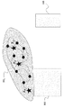
図1Aは、いくつかの実施形態によって対処される駐車シナリオの一例を示している。この例において、駐車空間150の境界は、L×Hのサイズを有する矩形によって表されている。車両100は、初期状態101、例えば、現在状態を有し、目標状態102によって規定された駐車スポットに駐車される必要がある。各状態、例えば、初期状態及び目標状態は、車両の位置及び方位を規定する。駐車空間150は、障害物を含む。障害物は、駐車空間のレイアウトの一部、すなわち、駐車空間の壁及び/又は柱等の常設の(permanent)障害物103とすることができる。常設の障害物の寸法は、通常既知である。図1Aは、そのような寸法の非限定的な例を示している。
FIG. 1A illustrates an example of a parking scenario addressed by some embodiments. In this example, the boundary of the
付加的又は代替的に、障害物は、他の駐車中であるか又は運動している車両104を含むことができる。車両104及び駐車することになる車両100の幾何学的寸法は、車両のタイプに基づいて求めることができる。明確にするために、本開示は、前輪駆動車両を検討するが、異なる実施形態は、後輪駆動車両及び全輪駆動(full wheel drive:四輪駆動)車両を含む他の車両に適用される。
Additionally or alternatively, the obstacle may include another parked or moving
いくつかの実施形態において、駐車空間のレイアウト及び障害物103の位置は、駐車空間のマップ上で指定される。そのようなマップは、所定のものとすることもできるし、駐車中又は駐車前にリアルタイムで構築することもできる。種々の実施形態は、初期状態と目標状態とを接続する運動学的経路105が実現可能でありかつ衝突を伴わないものであるように、この運動学的経路を求める。
In some embodiments, the layout of the parking space and the location of
図1Bは、いくつかの実施形態による、車両の幾何学的表現の一例示的な概略図を示している。この例において、車両は、矩形115として抽象化されている。車両状態は、この車両の後輪軸の中点を表す位置(x,y)110、及び、車体軸と水平軸との間の角度を示す方位θ120を含む。
FIG. 1B shows an exemplary schematic diagram of a geometrical representation of a vehicle, according to some embodiments. In this example, the vehicle is abstracted as a
車両が経路に沿って運動する速度を求める運動計画は、車両100の動的モデルを用いる。本明細書において用いられる場合、車両の動的モデルは、車両の状態における時間依存変化を説明する。動的モデルは、通常、微分方程式によって表される。1つの実施形態において、車両の動的モデルは、5次の微分方程式

経路計画のために、いくつかの実施形態は、車両の質量又は運動を引き起こす力を考慮しない車両の運動を記述する車両の運動学的モデルを用いる。 For path planning, some embodiments use a kinematic model of the vehicle that describes the motion of the vehicle without considering the mass of the vehicle or the forces that cause the motion.
1つの実施形態において、以下の運動学的モデルが考慮される。
或る経路が運動学的モデル(2)の解である場合、その経路は運動学的に実現可能である。車両状態X=(x,y,θ)は、位置Xに配置される車両がいかなる障害物とも衝突せず、かつ駐車空間の境界の内側に完全に収まる場合にのみ、衝突を伴わないものである。初期状態101は、X0=(x0,y0,θ0)として略式表現され(abbreviated)、目標状態102は、Xf=(xf,yf,θf)によって示される。矩形L×Hによって表される駐車空間での特定の駐車タスクについて、車両状態は、状態空間
![]()
![]()
いくつかの実施形態は、車両状態が衝突を伴わないものであるか否かを、駐車空間のマップとも称される、駐車空間の幾何学的表現に基づいて判断する。1つの実施形態において、駐車空間のマップは、全ての障害物及び駐車空間の境界を単純な幾何学的形状として近似することによって導出される。1つの実施形態において、環境(駐車空間と同等)内の障害物103は、障害物ごとに最小バウンディングボックスを構築することによって導出される矩形として近似することができる。障害物及び駐車空間の境界の幾何学的近似を用いて、駐車空間又は環境を、幾何学的オブジェクトのリストによって完全に記述することができる。
Some embodiments determine whether a vehicle condition is collision free or not based on a geometric representation of a parking space, also referred to as a map of the parking space. In one embodiment, the parking space map is derived by approximating all obstacles and parking space boundaries as simple geometric shapes. In one embodiment, the
図1Cは、図1Aの駐車シナリオに対応する駐車空間のマップ130を示している。双方のタイプの障害物が、矩形表現を用いて1つのタイプの常設障害物103としてともに統合される。障害物は、経路計画のために、搭載プロセッサの計算能力(computing power)に依拠して、複数の幾何学的形状によって近似することができる。例えば、別の実施形態において、計算能力が十分ではない場合、障害物は、障害物ごとにバウンディングサークルを構築することによって近似することができる。代替的に、障害物は、ポリトープによって近似することができるが、これにより、経路計画における計算負荷を高める場合がある。また、駐車空間内の障害物は、同一の幾何学的形状によって近似されない場合もある。
FIG. 1C shows a
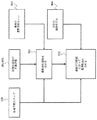
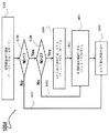
図2Aは、1つの実施形態による自動化駐車システムの機能図を示している。環境マッピング及びローカライゼーションブロック201は、駐車空間のマップを構築又は更新し、環境及び車両動作状態(vehicle operation condition)を検知することによって車両の現在ロケーションを求める。例えば、車両動作を検知するのに、3軸加速度計(複数の場合もある)、3軸ジャイロスコープ(複数の場合もある)、及び/又は磁力計(複数の場合もある)を備えることができる慣性測定ユニットを用いることができる。車両の位置及び速度を提供するのに全地球測位システムセンサーを用いることができる。環境200を検知するセンサーは、他の車両、歩行者、及び建物を含む障害物を捕捉するビデオカメラ、車両と障害物との間の距離を検出する超音波/レーダーセンサー、等とすることができる。1つの実施形態において、環境マップは、図1Cに示す駐車空間の幾何学的表現を生成するために更に処理される。
FIG. 2A shows a functional diagram of an automated parking system according to one embodiment. The environment mapping and
目標状態選択ブロック202は、車両を駐車する駐車スポットのための目標状態を、駐車場候補を識別することによって選択し、この目標状態を運動計画ブロック203に送信する。1つの実施形態において、利用可能な駐車スポットは、駐車施設の管理に関連付けられた別個のシステムによって追跡される。付加的又は代替的に、駐車スポットは、自動化駐車システムのセンサー230を用いて検出することができる。1つの実施形態において、運動計画ブロックは、チェックを行って、目標状態が、駐車可能(parkable)、すなわち、駐車スポットまでの実現可能経路があるか否かを判断し、目標状態選択ブロック202にチェック結果を通知する。目標状態が駐車可能でない場合、目標状態選択ブロック202は、評価のために別の目標状態を選択する。別の実施形態において、目標状態選択ブロック202は、目標状態が駐車可能であるか否かを評価し、駐車可能な目標状態のみを運動計画ブロックに送信することもできる。
Target state selection block 20 2, a target state for the parking spot to park the vehicle, select by identifying the parking candidate, and transmits the target state to
目標状態が駐車可能である場合、運動計画203は、全運動計画手順を開始し、車両モデル210、車両の初期状態及び目標状態、並びに駐車空間のマップに基づいて基準軌道241を求める。1つの実施形態において、基準軌道は、車両速度及び操舵角の経時的なプロファイルを規定する。別の実施形態において、基準軌道は、車両状態(x,y,θ)の経時的なプロファイルを規定する。
If the target state is parkable, the
基準軌道241が与えられると、車両コントローラー及びアクチュエーター204は、制御コマンドを求めるとともに実行して、基準軌道が状態プロファイルである場合、車両状態が基準軌道241を追跡することを強制し、又は、基準軌道が車両速度プロファイル及び操舵角プロファイルである場合、車両速度及び操舵角が基準軌道を追跡することを強制する。1つの実施形態において、制御コマンドは、ガスペダル圧力又は操舵トルクとすることができる。車両コントローラー/アクチュエーターは、制御コマンドを求めるために信号243も用いることができる。信号243は、測定操舵角、又はハンドル若しくはガスペダルを動かすモーターの測定電流とすることができる。
Given the
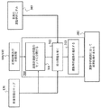
図2Bは、1つの実施形態による運動計画システム203の全体図を示している。運動計画システム203は、この運動計画システム203のモジュールを実行する少なくとも1つのプロセッサ270を備える。プロセッサ270は、車両のジオメトリ及び駐車空間のマップ等の幾何学的情報281を記憶するメモリ280に接続される(271)。メモリ280は、車両の運動学的モデル及び車両の動的モデル等の車両のモデル282も記憶することができる。メモリ280は、限定されるものではないが、車両の初期状態、駐車車両の目標状態、コスト関数、それぞれの計算された状態の値、各状態に至る運動、幾何学的グラフ、運動学的グラフ、通過点、基準軌道を含む、運動計画器の内部情報283も記憶することができる。いくつかの実施形態において、メモリ280は、自動化駐車の方法を実施する記憶命令を含むことができ、ここで、命令は、プロセッサ270によって実行されると、方法の少なくともいくつかのステップを実行する。
FIG. 2B shows a general view of the
いくつかの実施形態は、駐車問題を、少なくとも2つのステージを用いて解くことができるという認識に基づいている。第1のステージにおいて、車両の初期状態を目標状態と接続する運動学的経路が構築される。第2のステージにおいて、この運動学的経路を辿る実際の軌道が求められる。運動学的経路は、車両の動的モデルよりも単純である運動学的モデルを用いて構築することができるので、このような手法は有利である。 Some embodiments are based on the recognition that parking problems can be solved using at least two stages. In the first stage, a kinematic path is established that connects the initial state of the vehicle with the target state. In the second stage, the actual trajectory following this kinematic path is determined. Such an approach is advantageous because the kinematic path can be constructed using a kinematic model that is simpler than the dynamic model of the vehicle.
図3Aは、いくつかの実施形態による運動計画203のステージのブロック図を示している。ブロック301は、車両のジオメトリ及び駐車空間のマップ130、車両の初期状態101及び目標状態102、並びに車両の運動学的モデル303に基づいて運動学的経路を求める。運動学的経路は、ブロック302において更に処理されて、車両の動的モデル304の解である基準軌道が生成される。
FIG. 3A illustrates a block diagram of stages of a
このような問題分割により、当初の駐車問題を以下の問題に再定式化することができる。車両のジオメトリ、駐車空間のマップ、及び車両の運動学的モデルが与えられると、本明細書において運動学的経路と称される、初期状態を目標状態に接続する、実現可能でありかつ衝突を伴わない経路を発見する。運動学的な実現可能性は、運動学的経路が初期状態をその初期値とする車両運動学の解であり、したがって、この運動学的経路を、車両が初期状態で開始して辿ることができることを確実にする。衝突を伴わないという特性は、車両が、運動学的経路に沿って運動する間、駐車空間において障害物と衝突しないことを保証する。 By such problem division, the initial parking problem can be reformulated into the following problems. Given the geometry of the vehicle, the map of the parking space, and the kinematic model of the vehicle, which is referred to herein as the kinematic path, connecting the initial state to the target state, a feasible and collision-free Discover routes that are not accompanied. Kinematic feasibility is a solution of vehicle kinematics whose initial value is the kinematic path, and therefore this kinematic path is not traversable starting with the vehicle in the initial state. Make sure you can. The collision-free property guarantees that the vehicle does not collide with obstacles in the parking space while moving along the kinematic path.
運動学的モデルが通常、車両の動的モデルよりも単純であるにもかかわらず、運動学的経路の運動学的実現可能性について駐車空間全体をサンプリングしてテストする必要がある場合、自動化駐車問題の解は、依然として計算上非実用的である可能性がある。高速道路を走行する車両についての経路計画と比較して、車両の自動化駐車システムの経路計画は、固有の特性を有する。すなわち、環境内の衝突を伴わない空間は、通常、非常に狭小であり、サンプリングに基づくアルゴリズムが遥かに低速で駐車空間を探索することが必要とされる。結果として、衝突を伴わない空間において2つの状態を接続する運動学的経路をリアルタイムで構築することは、より困難である。 If the kinematic model is usually simpler than the dynamic model of the vehicle, but the entire parking space needs to be sampled and tested for kinematic feasibility of the kinematic path, automated parking The solution to the problem may still be computationally impractical. Compared with route planning for vehicles traveling on highways, route planning for automated vehicle parking systems has unique characteristics. That is, the collision-free space in the environment is usually very small, requiring a sampling-based algorithm to search the parking space much slower. As a result, it is more difficult to construct in real time a kinematic path connecting two states in a collision free space.
図3Bは、駐車空間全体の状態のサンプリングを介した運動学的経路301の、計画部分問題312のセットへの分割(311)決定の概略図を示している。運動学的経路313は、部分問題312の解の和集合から選択される。
FIG. 3B shows a schematic diagram of the partitioning (311) decision of the
いくつかの実施形態は、各部分問題の解を接続して、初期状態と目標状態とを接続する実現可能な運動学的経路を求めることができるように、駐車空間問題のサンプリングを部分問題のセットに分割する必要があるという認識に基づいている。加えて、部分問題のセットへの分割は、分割された駐車空間をサンプリングする方法についての指針を提供するべきである。これは、一般的なサンプリング問題において、サンプリングされた状態は、初期状態と目標状態とが比較的離れている場合、駐車空間において構築される運動学的ツリーの近くにあり、このツリーに追加される確率が低いためである。この低い確率は、運動学的ツリーへの近接性を求めるために行われる計算が無駄になる可能性の方が高いことを意味する。近接性の検出における計算の無駄を回避するために、サンプリングされた状態は、双方のツリーから離れているものの、運動学的ツリーの近傍として扱うことができる。一方で、そのように扱うことで、必然的に、衝突検出においてより多くの計算の無駄がもたらされる。これは、双方のツリーから比較的離れていても運動学的ツリーに対する近傍として扱われるサンプリングされた状態について、このサンプリングされた状態と双方のツリーとの間の衝突を伴わない接続を有する確率は低いためである。低確率イベントを検出するのに適用されるいずれの計算も、無駄になる可能性が最も高く、したがって、低計算効率を招く。 Some embodiments sample the parking space problem into sub-problems so that the solutions of each sub-problem can be connected to determine a feasible kinematic path connecting the initial and target states. It is based on the recognition that it needs to be divided into sets. In addition, the division into sub-problem sets should provide guidance on how to sample the divided parking space. This is because in a general sampling problem, the sampled state is near the kinematic tree constructed in the parking space and is added to this tree when the initial state and the target state are relatively far apart. This is because the probability of This low probability means that the calculations performed to find the proximity to the kinematic tree are more likely to be wasted. To avoid wasting computation in proximity detection, the sampled states can be treated as a neighborhood of the kinematic tree, although they are far from both trees. On the other hand, such treatment inevitably leads to more computational waste in collision detection. This means that for a sampled state that is treated as a neighborhood for the kinematic tree even though it is relatively far from both trees, the probability of having a collision-free connection between this sampled state and both trees is Because it is low. Any calculations applied to detect low probability events are most likely to be wasted, thus leading to low computational efficiency.
いくつかの実施形態は、車両の初期状態を、通過点のセットを通じて駐車車両の目標状態と接続する衝突を伴わない幾何学的経路を用いて、運動学的経路を構築するために、サンプリング問題を部分問題のセットに分割することができ、それにより、サンプリングの計算効率を高めるとともに実現可能な運動学的経路を提供することができるという理解に基づいている。 Some embodiments use a sampling problem to construct a kinematic path using a collision-free geometric path that connects the initial state of the vehicle with the target state of the parked vehicle through a set of transit points. It is based on the understanding that can be divided into a set of subproblems, which can increase the computational efficiency of sampling and provide feasible kinematic paths.
図4Aは、運動学的経路計画問題を部分問題のセットに分割することのブロック図を示している。この分割することは、車両の初期状態及び目標状態及びジオメトリ、並びに駐車空間に基づいて通過点のセットを生成するブロック411に依拠している。各通過点は、中間目標(milestone)車両状態を規定する。通常、最初の通過点は初期状態X0に対応し、最後の通過点は目標状態Xfに対応する。また、通過点のセットは、以下の接続特性、すなわち、全ての通過点が衝突を伴わないエッジと接続されることを満たすものとし、ここで、エッジは、2つのノード(又は状態)間の幾何学的接続又は運動学的接続を表すことができる。1つの実施形態において、2つの任意の状態X1、X2が与えられると、これらの状態の間の幾何学的エッジは、直線とすることができ、これらの状態の間の運動学的エッジは、車両運動学(2)と、0≦t1≦t2<∞で範囲付けされた任意のものについて、境界条件X(t1)=X1、X(t2)=X2とを満たす任意の実現可能な解とすることができる。 FIG. 4A shows a block diagram of partitioning a kinematic path planning problem into a set of subproblems. This partitioning relies on block 411 which produces a set of waypoints based on the initial and target states and geometry of the vehicle and the parking space. Each passing point defines a milestone vehicle state. Usually, the first passing point corresponds to the initial state X 0 and the last passing point corresponds to the target state X f . Also, the set of transit points shall satisfy the following connection characteristics: all transit points are connected to edges without collision, where an edge is between two nodes (or states). Geometric or kinematic connections can be represented. In one embodiment, given two arbitrary states X 1 , X 2 , the geometric edge between these states can be a straight line, and the kinematic edge between these states can be Is the vehicle kinematics (2) and the boundary conditions X(t 1 )=X 1 and X(t 2 )=X 2 for any ranged 0≦t 1 ≦t 2 <∞. It can be any feasible solution that satisfies.
例えば、通過点を介した幾何学的経路は、車両のジオメトリ及び駐車空間のマップのみを用いて、すなわち、車両の運動学的モデル又は動的モデルを考慮することなく構築することができる。このようにして、幾何学的経路の計算が単純化される。幾何学的経路の衝突を伴わないという特性は、衝突を伴わない運動学的経路を幾何学的経路の上に構築することができる可能性を高める。加えて、各通過点が車両の位置及び方位を規定する通過点の対は、サンプリング問題の有利な分割を提供する。 For example, a geometrical path through a passing point can be constructed using only the geometry of the vehicle and a map of the parking space, i.e. without considering the kinematic or dynamic model of the vehicle. In this way the calculation of the geometrical path is simplified. The collision-free property of geometrical paths increases the possibility that collision-free kinematic paths can be built on top of geometrical paths. In addition, the pairs of passing points, where each passing point defines the position and orientation of the vehicle, provide an advantageous division of the sampling problem.
図4Bは、運動学的経路計画問題を部分問題のセットに分割するのに用いられる通過点のセットを有する、図1Aの駐車シナリオの概略図を示している。通過点のセットは、車両状態X0,...,X5を規定し、ここで、各通過点は、車両の位置及び方位を含む車両状態を規定する。通過点X0及びX5は、それぞれ初期状態及び目標状態に対応する。例えば、状態X1に対応する通過点は、車両の位置420及び方位425を規定する。同様に、状態X2に対応する通過点は、車両の位置430及び方位435を規定する。これらの通過点は、衝突を伴わないものであり、衝突を伴わない幾何学的エッジ、例えば、直線427及び437と接続される。
FIG. 4B shows a schematic diagram of the parking scenario of FIG. 1A with a set of passing points used to divide the kinematic path planning problem into a set of subproblems. The set of passing points is represented by vehicle states X 0,. . . , X 5 where each passing point defines a vehicle condition including the position and orientation of the vehicle. The passing points X 0 and X 5 correspond to the initial state and the target state, respectively. For example, the passing point corresponding to state X 1 defines
いくつかの実施形態は、車両の運動学的モデルを用いて、近傍の通過点の各対を接続する運動学的サブグラフのセットを求めて運動学的グラフを形成する。例えば、各部分問題は、「2つの隣接した通過点を接続する運動学的経路を発見する」こととして定式化することができる。全ての部分問題を解くことができる場合、初期状態は、運動学的経路を通じて目標状態に接続することができる。これは、当初の経路計画問題が解かれることを更に暗示する。 Some embodiments use a kinematic model of the vehicle to determine a set of kinematic subgraphs connecting each pair of nearby transit points to form a kinematic graph. For example, each subproblem can be formulated as "finding a kinematic path that connects two adjacent transit points." If all subproblems can be solved, the initial state can be connected to the target state through a kinematic path. This further implies that the original path planning problem is solved.
図4Cは、車両を駐車空間内に駐車する方法のブロック図を示している。この方法は、車両のジオメトリ及び駐車空間のマップ440を記憶するメモリに結合されたプロセッサを用いる。メモリは、車両の運動学的モデル303及び車両の動的モデル304も記憶することができる。プロセッサは、方法を実施する記憶命令に結合され、ここで、命令は、プロセッサによって実行されると、方法の少なくともいくつかのステップを実行する。
FIG. 4C shows a block diagram of a method of parking a vehicle in a parking space. The method uses a processor coupled to a memory that stores a
方法は、車両のジオメトリ及び駐車空間のマップ440を用いて、車両の初期状態を、通過点のセットを通じて駐車車両の目標状態と接続する、衝突を伴わない幾何学的経路455を求める(450)。各通過点は、例えば、図4Bに示すような車両の位置及び方位を規定する。方法は、車両の運動学的モデル303を用いて、運動学的エッジと接続された複数のノードを有する運動学的グラフを形成する運動学的サブグラフのセットを求める(460)。各運動学的サブグラフは、近傍の通過点の対を接続し、各ノードは、車両の状態を規定し、2つのノードを接続する各運動学的エッジは、車両の運動学的特性に従って2つのノードを接続する、衝突を伴わない運動学的経路を規定する。
The method uses the vehicle geometry and
図4Dは、1つの実施形態による、運動学的グラフを形成する運動学的サブグラフのセットの一例を示している。この例において、運動学的グラフ445は、4つの運動学的サブグラフ446、447、448、及び449によって形成される。例えば、サブグラフの各々は、反復的に、例えば、通過点のセットに対応するシードのセットから反復的に、成長させることができる。
FIG. 4D illustrates an example set of kinematic subgraphs forming a kinematic graph, according to one embodiment. In this example,
とりわけ、近傍の通過点は、通常、互いの方が車両の初期状態及び目標状態よりも近くにあるので、駐車空間のバイアスサンプリングを用いて各運動学的サブグラフを構築することができる。そのために、状態の各新たなサンプルは、運動学的サブツリーのうちの1つに追加される可能性の方が高く、したがって、計算の無駄を低減する。 Notably, since the nearby pass points are typically closer to each other than the vehicle's initial and target states, parking space bias sampling can be used to construct each kinematic subgraph. As such, each new sample of states is more likely to be added to one of the kinematic subtrees, thus reducing computational waste.
1つの実施形態において、部分問題は、逐次的に解かれる。例えば、部分問題1は、第1の通過点X0に対応する初期ノードと第2の通過点X1に対応するノードとを接続する運動学的サブグラフSG1を発見することとして構築され、部分問題2は、運動学的サブグラフSG1を第3の通過点X2と接続する運動学的サブグラフSG2を発見することとして構築され、以下同様であり、最終的に、最後の部分問題は、最後から1つ前の運動学的サブグラフSGM−1を、最後の通過点XMと接続する運動学的グラフを発見することとして構築される。別の実施形態において、部分問題は並列的に解かれ、したがって、計算速度を桁違いに高速化する。並列的に解かれる部分問題は、逐次的に解かれる部分問題とは異なるものとすることができる。
In one embodiment, the subproblems are solved sequentially. For example,
図5Aは、いくつかの実施形態による、幾何学的経路を求める方法のフローチャートを示している。方法は、初期ノードを、衝突を伴わないノードのセットを通じて目標ノードと接続する幾何学的グラフGGを構築する(501)。幾何学的グラフ内のノードの各対は、車両及び駐車空間のジオメトリのみを用いて求められる、衝突を伴わないエッジと接続される。幾何学的グラフは、幾何学的グラフ内のノード間のエッジが運動学的ではなく幾何学的であることを除いて運動学的グラフに類似している。幾何学的エッジを利用することにより、幾何学的グラフは、運動学的グラフよりも遥かに高速に構築することができる。次に、方法は、幾何学的経路の通過点のセットを形成する幾何学的グラフから、ノードのセットを選択する(502)。 FIG. 5A shows a flow chart of a method for determining a geometric path, according to some embodiments. The method constructs a geometric graph GG that connects an initial node with a target node through a set of nodes without collision (501). Each pair of nodes in the geometric graph is connected to a collision-free edge, which is determined using only the vehicle and parking space geometry. Geometric graphs are similar to kinematic graphs except that the edges between the nodes in the geometric graph are geometric rather than kinematic. By utilizing geometric edges, geometric graphs can be constructed much faster than kinematic graphs. Next, the method selects 502 a set of nodes from the geometric graph forming a set of transit points of the geometric path.
例えば、1つの実施形態において、幾何学的グラフは、車両及び駐車空間のジオメトリに従った衝突を伴わない接続のために、例えば一様に又はランダムに駐車空間の状態空間をサンプリングして、サンプリングされた近傍の状態間の接続をテストすることによって構築される。単一の衝突を伴わない接続を有しないサンプリングされた状態は剪定され、サンプル状態の残りが幾何学的グラフのノードを形成する。 For example, in one embodiment, the geometric graph may be sampled, for example, by uniformly or randomly sampling the state space of the parking space for collision-free connectivity according to the geometry of the vehicle and the parking space. It is constructed by testing the connections between states in the specified neighborhood. Sampled states that do not have a single collision-free connection are pruned, and the rest of the sample states form the nodes of the geometric graph.
図5Bは、1つの実施形態による、幾何学的グラフを構築することの概略図を示している。この例において、幾何学的グラフは、初期状態101に対応する初期ノード511を有する初期幾何学的ツリーGTi521と、目標状態102に対応する目標ノード512を有する目標幾何学的ツリーGTt522とを用いて双方の端点から構築される。初期幾何学的ツリーは、ノードセットVGTi及びエッジセットEGTiを有する。目標幾何学的ツリーは、ノードセットVGTt及びエッジセットEGTtを有する。
FIG. 5B shows a schematic diagram of building a geometric graph, according to one embodiment. In this example, the geometric graph is an initial
現在の反復中、X=(x,y,θ)で示す状態510は、或る特定のサンプリングスキームに従ってサンプリングされ、衝突を伴わないものであることが検証されている。次に行われるのは、最近傍のノード、例えば、初期幾何学的ツリー上に位置するノード530を求めることである。初期ツリー521からの最近傍のノード530とサンプリングされた状態510との間の幾何学的エッジ535が衝突を伴わないものである場合、サンプリングされた状態510に対応する新たなノードが作成されて初期幾何学的ツリーのノードセットに追加されるとともに、エッジ535が初期幾何学的ツリーのエッジセットに追加される。
During the current iteration, the
サンプリングされた状態510について、目標幾何学的ツリーに同様の手順が適用される。すなわち、目標幾何学的ツリー522上に位置する最近傍のノード540が特定される。ノード540とサンプリングされた状態との間の幾何学的エッジ545が衝突を伴わないものである場合、サンプリングされた状態に対応する新たなノードが作成されて目標幾何学的ツリーのノードセットに追加されるとともに、エッジ545が目標幾何学的ツリーのエッジセットに追加される。エッジ535及び545の双方が衝突を伴わないものである場合、初期幾何学的ツリーと目標幾何学的ツリーとが接続され、その場合、初期ノードと目標ノードとが接続される。そのために、幾何学的グラフは、初期幾何学的ツリーと目標幾何学的ツリーとの和集合である。
A similar procedure applies to the target geometric tree for the sampled states 510. That is, the nearest node 540 located on the target
付加的又は代替的に、いくつかの実施形態は、到達可能性基準を用いてサンプリングを実行する。到達可能性基準に従って、状態空間内のサンプルは、このサンプルが既に構築されているグラフから到達可能である場合にのみ保存される。1つの実施形態において、到達可能性をテストするのに車両の動態の使用を回避するために、到達可能性は、到達不可能性(non−reachability:到達不可能範囲)の欠如として定義され、到達不可能性は、車両の側部付近の所定のエリアである。 Additionally or alternatively, some embodiments perform the sampling using reachability criteria. According to the reachability criterion, a sample in the state space is saved only if this sample is reachable from the already constructed graph. In one embodiment, reachability is defined as a lack of non-reachability to avoid the use of vehicle dynamics to test reachability, Unreachability is a predetermined area near the side of the vehicle.
図5Cは、車両の位置及び方位を規定する状態510における、車両100の到達不可能エリア553及び557の例の概略図を示している。この例において、到達不可能エリアは、車両の車輪を最大限左又は右に向けた状態で、状態510において開始して所定の速度で運動する車両運動の円によって表される。以前にサンプリングされた状態530が到達不可能エリア553及び557内にある場合、状態510は、状態530のノードに接続されない。幾何学的グラフの全てのノードがサンプリングされた状態の到達不可能エリア内にある場合、そのサンプリングされた状態は、拒絶される。
FIG. 5C shows a schematic diagram of an example of
図5Dは、1つの実施形態による、幾何学的グラフを構築する方法のフローチャートを示している。この実施形態において、サンプリングされた状態Xは、衝突を伴わないことがテストされることに加えて、通過点の品質を改善するために或る特定の運転可能性基準によって評価される。運転可能性基準は、運動学的グラフの構築において計算効率を改善することができる。 FIG. 5D shows a flowchart of a method of constructing a geometric graph, according to one embodiment. In this embodiment, the sampled state X, in addition to being tested for collision-free, is evaluated by certain drivability criteria to improve the quality of the passing points. Drivability criteria can improve computational efficiency in the construction of kinematic graphs.
方法は、駐車場の状態空間内の点をサンプリングして(550)、サンプリングされた状態を生成する。幾何学的グラフのノードに対応する全ての状態がサンプリングされた状態の到達不可能エリア内にある場合(560)、サンプリングされた状態は拒絶される(555)。そうではない場合、方法は、サンプリングされた状態に最も近い状態を有する幾何学的グラフの最近傍のノードを求め(570)、サンプリングされた状態のノードを幾何学的グラフに追加して、この追加されたノードを、エッジが衝突を伴わない場合にこのエッジを介して最近傍のノードに接続する(580)。 The method samples (550) a point in the parking lot state space to produce a sampled state. If all states corresponding to nodes in the geometric graph are within the unreachable area of the sampled state (560), the sampled state is rejected (555). Otherwise, the method finds (570) the nearest node in the geometric graph that has the state closest to the sampled state and adds the sampled state node to the geometric graph to The added node is connected (580) to the nearest node via the edge if the edge does not involve a collision.
方法は、サンプリングすること、拒絶すること、求めること、及び追加することを、初期ノードが目標ノードに接続されるまで繰り返す。例えば、1つの実施形態において、幾何学的グラフの構築は、初期幾何学的ツリーと目標幾何学的ツリーとが接続されている限り、停止される。別の実施形態において、幾何学的グラフの構築は、或る特定の数のサンプリングされた状態が初期幾何学的ツリーと目標幾何学的ツリーとの双方に追加されるまで、停止される。 The method repeats sampling, rejecting, seeking, and adding until the initial node is connected to the target node. For example, in one embodiment, the construction of the geometric graph is stopped as long as the initial and target geometric trees are connected. In another embodiment, the construction of the geometric graph is stopped until a certain number of sampled states have been added to both the initial and target geometric trees.
幾何学的グラフは、初期ノードが目標ノードと接続されるような、ノード間の幾何学的接続を表すノード及びエッジを含む。幾何学的グラフが与えられると、初期状態から目標状態への多くの幾何学的経路が存在し得る。或る特定のコスト関数を低減する幾何学的グラフからの幾何学的経路を選択することが有利である。例えば、1つの実施形態は、2つのステップ、すなわち、a)ノードごとにコストを求めるステップであって、ここで、ノードコストは、そのノードによって指定される状態から目標状態への最小コストを表す、ステップと、b)初期ノードから開始し、ノードコストに従ってノードのセットを選択するステップであって、ここで、初期ノードのコストは、車両がノードのセットを通過する場合にのみ最小に達する、ステップとを実行することによって幾何学的経路を選択する。 The geometric graph includes nodes and edges that represent the geometrical connections between nodes such that the initial node is connected to the target node. Given a geometric graph, there can be many geometric paths from the initial state to the target state. It is advantageous to choose a geometric path from the geometric graph that reduces a certain cost function. For example, one embodiment is two steps: a) determining the cost for each node, where the node cost represents the minimum cost from the state specified by that node to the target state. , And b) selecting a set of nodes according to the node cost, starting from the initial node, wherein the cost of the initial node reaches a minimum only if the vehicle passes through the set of nodes, Select the geometric path by performing steps and.
ノードコストは、エッジのコストによって求められる。それぞれ車両状態Xi、Xjに対応する2つのノードNi、Njを所与とし、Ni及びNjがエッジEi,jによって接続されると仮定する。エッジEi,jのコストは、ベクトルノルム:
![]()
![]()
1つの実施形態において、全てのノードについてV0(Ni)=0である。k→∞の場合、Vk(Ni)は、ノードNiの最小コストに収束し、したがって、ノードの最小コストは、価値反復によって得ることができることが確立されている。価値反復は、反復的に行われ、この反復は、実用上、或る特定の基準に従って停止されなければならない。1つの実施形態において、反復は、kが事前設定された大きな正の数に達すると停止する。別の実施形態において、反復は、全てのノードについて|Vk(Ni)−Vk−1(Ni)|が或る閾値未満になると停止する。 In one embodiment, V 0 (N i )=0 for all nodes. It has been established that for k→∞, V k (N i ) converges to the minimum cost of the node N i , so that the minimum cost of the node can be obtained by value iteration. The value iteration is iterative, and in practice this iteration must be stopped according to certain criteria. In one embodiment, the iterations stop when k reaches a preset large positive number. In another embodiment, the iteration stops when |V k (N i )−V k−1 (N i )| falls below some threshold for all nodes.
価値反復からもたらされるノードNiの最小コストをV(Ni)と表すものとする。最良の幾何学的経路を表すノードのセットは、方策反復を実行することによって求められる。すなわち、Niが最良の幾何学的経路のうちの1つのノードであると仮定すると、Niの次のノードは、
![]()
![]()
一例として、図5Eにおいて、初期状態に対応する初期ノードから開始するとともに目標ノードにおいて停止する方策反復を、幾何学的グラフに適用することにより、緑色の線によって表される最良の幾何学的経路、及び車両状態X0,X1,...,X5に対応するノードのセットが与えられる。 As an example, in FIG. 5E, by applying to the geometric graph a policy iteration starting from the initial node corresponding to the initial state and stopping at the target node, the best geometric path represented by the green line. , And vehicle states X 0 , X 1 ,. . . , X 5 is given a set of nodes.
別の実施形態において、最良の幾何学的経路は、3つのステップ、すなわち、a)初期ノード及び目標ノードを除く全ての葉ノードを除去することによって幾何学的グラフをトリミングするステップであって、ここで、葉ノードは1つのみの近傍のノードを有する、ステップと、b)トリミング後に幾何学的グラフにわたって価値反復を実行することによって各ノードの最小コストを求めるステップと、c)トリミング後に初期ノードから開始して、幾何学的グラフに従ってノードのセットを選択するステップとによって求められる。この実施形態は、最良の幾何学的経路がいずれの葉ノードも含まず、したがって、トリミング後に幾何学的グラフにわたって価値反復を実行することにより、全ての非葉ノードの同じ最小コストが与えられるという理解に基づいている。この実施形態は、ノードの最小コスト、及び最良の幾何学的経路を求める計算負荷を大幅に低減することができる。最良の幾何学的グラフを規定するノードのセットから通過点のセットを抽出することができる。 In another embodiment, the best geometric path is three steps: a) trimming the geometric graph by removing all leaf nodes except the initial and target nodes, Where a leaf node has only one neighbor node, and b) determining the minimum cost of each node by performing value iteration over the geometric graph after trimming, and c) initializing after trimming. Starting with the nodes and selecting a set of nodes according to the geometric graph. This embodiment states that the best geometric path does not include any leaf nodes, so performing value iteration over the geometric graph after trimming gives the same minimum cost for all non-leaf nodes. It is based on understanding. This embodiment can significantly reduce the minimum cost of a node and the computational load of finding the best geometric path. A set of transit points can be extracted from the set of nodes that define the best geometric graph.
図5Eは、1つの実施形態による、幾何学的経路455を選択する方法のブロック図を示している。方法は、幾何学的グラフの初期ノード及び各非葉ノードについて、目標ノードに到達する最小コストを求め(591)、初期ノードを、初期ノードについて求められた最小コストを有する目標ノードと接続するノードのセットを選択して(593)幾何学的経路の通過点のセットを形成する。例えば、ノードのコストを求める前に、方法は、初期ノード及び目標ノードを除く葉ノードを幾何学的グラフから除去するとともに、除去された葉ノードを接続するエッジを幾何学的グラフから除去することができる。
FIG. 5E illustrates a block diagram of a method of selecting
図6Aは、1つの実施形態による、通過点のセットによって規定される幾何学的経路455を用いて、計画問題を部分問題のセットに分割することのブロック図を示している。図6B、図6C、及び図6Dは、図6Aの部分問題のセットに対処するように構築された運動学的サブグラフのセットを示している。例えば、第1の部分問題601は、X0とX1とを接続する、すなわち、初期状態を、第2の通過点と接続する第1の運動学的サブグラフSG1を構築することと定義される。図6Bは、運動学的サブグラフSG1がX0とX1とを運動学的に接続するように構築されることを示している。
FIG. 6A shows a block diagram of partitioning a planning problem into a set of subproblems using a
第2の部分問題602は、第1の運動学的サブグラフSG1とX2とを接続する、すなわち、第2の通過点を、第3の通過点と接続する第2の運動学的サブグラフSG2を構築することと定義される。図6Cは、運動学的サブグラフSG2がSG1とX2とを運動学的に接続するように構築されることを示している。最後の部分問題M609は、SGM−1とXMとを接続する運動学的グラフKGを構築することと定義される。図6Dは、運動学的サブグラフSGM−1と、運動学的グラフKGがSGM−1とXMとを運動学的に接続するように構築されることとを示している。上述の定義の部分問題は、プロセッサにおいて逐次的に実行することができる。
The
図7Aは、1つの実施形態による、部分問題を逐次的に解く方法のブロック図を示している。方法は、セット475からの2つの隣接した通過点710ごとに運動学的グラフ740を逐次的に(730)構築する(720)。グラフ740が構築された後、方法は、成功770又は失敗760の終了条件が満たされるまで、次の対710に移る(750)。
FIG. 7A shows a block diagram of a method for sequentially solving subproblems according to one embodiment. The method sequentially (730) builds (720) a
図7Bは、通過点のセットを用いて部分問題を定式化する代替的な一実施形態の概略図を示している。部分問題780及び790は、それぞれ{X0,X1},...,{XM−1,XM}を接続する運動学的サブグラフSG1,...,SGMを構築することと定義される。全てのサブグラフが接続されている限り、運動学的グラフはサブグラフの和集合と定義され、接続されている。この実施形態における部分問題は、並列的に解くことができる。
FIG. 7B shows a schematic diagram of an alternative embodiment for formulating a subproblem with a set of transit points.
とりわけ、近傍の通過点は、通常、互いの方が車両の初期状態及び目標状態よりも近くにあるので、駐車空間のバイアスサンプリングを用いて各運動学的サブグラフを構築することができる。そのために、状態の各新たなサンプルは、運動学的サブツリーのうちの1つに追加される可能性の方が高く、したがって、計算の無駄を低減する。 Notably, since the nearby pass points are typically closer to each other than the vehicle's initial and target states, parking space bias sampling can be used to construct each kinematic subgraph. As such, each new sample of states is more likely to be added to one of the kinematic subtrees, thus reducing computational waste.
図8は、1つの実施形態による、運動学的グラフを求める方法のブロック図を示している。方法は、通過点のセットに近接する駐車空間をサンプリングして(810)、サンプリングされた状態815を生成する。そのようにして、サンプリングされた状態は、通過点のうちの少なくとも1つの状態にバイアスされる。例えば、サンプリングは、通過点の状態の関数として平均及び共分散を有する駐車空間の状態の確率分布を用いて実行することができる。
FIG. 8 shows a block diagram of a method for determining a kinematic graph, according to one embodiment. The method samples (810) the parking space proximate to the set of transit points to produce a sampled
方法は、サンプリングされた状態を、ツリーを更新するために、運動学的エッジが衝突を伴わないものである場合にこの運動学的エッジを用いて少なくとも1つの通過点から開始する少なくとも1つのツリーと接続し(820)、終了条件が満たされるまでサンプリングすること及び接続することを繰り返す(830)。例えば、終了条件は、接続された幾何学的グラフの形成、運動学的グラフ上で初期ノードと目標ノードとを接続する経路の数が或る閾値を超えること、近傍の通過点のツリーに接続するノードの数、のうちの1つ又は組み合わせを含むことができる。 The method uses the kinematic edge to update the tree from the sampled state to at least one tree starting from at least one transit point when the kinematic edge is collision free. (820), and repeats sampling and connecting (830) until the termination condition is met. For example, the termination condition is formation of a connected geometric graph, the number of paths connecting an initial node and a target node on a kinematic graph exceeds a certain threshold, and a tree of neighboring passing points is connected. One or a combination of the number of nodes to play.
図9Aは、1つの実施形態による、部分問題i+1を解く一例示的な方法のブロック図を示している。部分問題i+1は、通過点Xi及びXi+1、駐車空間のジオメトリ、及び車両の運動学的モデルから運動学的サブグラフSGi+1を構築する(720)ことを強制する。サブグラフSGi+1は、サブグラフSGiとXi+1とを接続するように構築される。例えば、サブグラフSGiは、根ノードが状態X0に対応する初期運動学的ツリーとして見ることができる。目標運動学的ツリーKTtは、部分問題i+1の目標状態として扱われ、状態Xi+1を有する根ノードで初期化される。バイアスされたサンプリングブロック901は、確率密度関数P(X)に従って状態空間
![]()
![]()
![]()
![]()
バイアスされたサンプリング901及び接続902を含む上述のステップは、或る特定の停止基準が満たされるまで繰り返される。1つの実施形態において、基準は、サンプリングされた状態XがサブグラフSGi及び運動学的目標ツリーの双方に追加される場合である。別の実施形態において、基準は、サブグラフSGi及び運動学的目標ツリーKTtの双方に追加されるサンプリングされた状態の数が或る閾値を超える場合である。
The above steps, including
図9Bは、1つの実施形態による、バイアスされたサンプリング901の一実施態様のブロック図を与えている。確率密度関数P(X)は、まず、通過点Xi及びXi+1の関数として構築される(911)。ブロック912において、サンプリングされた状態が、その確率密度関数がP(X)に一致するように生成される。サンプリング912は、サンプリングされた状態が衝突を伴わないもの(913)になるまで(914)、繰り返される。
FIG. 9B provides a block diagram of one implementation of
例えば、サンプリングは、通過点の状態の関数として平均及び共分散を有する駐車空間の状態の確率分布を用いて実行される。1つの実施形態において、確率分布は、ガウス分布である。 For example, the sampling is performed using a probability distribution of the states of the parking space with the mean and covariance as a function of the states of the transit points. In one embodiment, the probability distribution is a Gaussian distribution.
図9Cは、平均μ及び共分散σがXi及びXi+1の関数であるガウス確率密度関数P(X)920を用いる1つの実施形態による、バイアスされたサンプリングの方法のブロック図を示している。スカラー調整パラメーター0≦λμ≦1を定義すると、ガウス分布の平均値は以下によって与えられる。
![]()
![]()
ガウス分布の対角共分散行列は、σ=diag(λxσx,λyσy,λθσθ)として計算され、ここでσx、σy、σθは、式
![]()
![]()
別の実施形態において、確率密度関数P(X)は、平均μ及び共分散σがXi及びXi+1を含む通過点のセットの関数であるガウス過程である。 In another embodiment, the probability density function P(X) is a Gaussian process whose mean μ and covariance σ is a function of the set of passing points containing X i and X i+1 .
図10は、1つの実施形態による、運動学的グラフKG465から運動学的経路を選択する方法のブロック図を示している。方法は、初期ノード及び目標ノードを除く全ての葉ノードを除去することによって運動学的グラフをトリミングし(1001)、ここで、葉ノードは、運動学的エッジで1つの近傍のノードにのみ接続される。方法は、運動学的グラフにわたって、幾何学的グラフの場合と同じように、価値反復を実行することによって各ノードの最小コストを求める(1002)。初期ノードから開始して、ブロック1003は、ノードコスト及び運動学的グラフに従って初期運動学的経路を選択する。1つの実施形態において、ブロック1003は、幾何学的グラフからの最良の幾何学的経路(通過点のセットと同等)の選択において採用される方策反復を用いて初期運動学的経路を選択する。例えば、初期運動学的経路は、初期ノード及び目標ノードを含むノードのセットを含む。ブロック1004は、初期運動学的経路を平滑化して、初期状態から開始して目標状態において終端する運動学的経路を生成する。
FIG. 10 shows a block diagram of a method of selecting a kinematic path from a kinematic graph KG465, according to one embodiment. The method trims (1001) the kinematic graph by removing all leaf nodes except the initial and target nodes, where the leaf nodes connect to only one neighbor node at the kinematic edge. To be done. The method finds the minimum cost of each node (1002) over the kinematic graph by performing value iterations, as in the geometric graph. Starting from the initial node,
図11Aは、1つの実施形態による、初期運動学的経路1110を平滑化する(1004)フローチャートを示している。いくつかの実施形態において、運動学的経路を平滑化することは、運動学的経路において後続する通過点に到達するのに不必要である中間通過点を除去することを含む。例えば、初期運動学的経路P0={X0,...,XM}が与えられると、ブロック1004は、M≦1である場合(1120)、何も行わず、すなわち、経路を返す(1125)。M=2である場合、中間経路は、初期運動学的経路P0と定義され、これは1012でラベル付けされている。M>2である場合(1130)、ブロック1004は、部分経路PS={X1,...,XM}の平滑化を試みて(1140)、平滑化された部分経路SPSを生成し、中間経路{X0,SPS}を返し、これは1013でラベル付けされている。ブロック1011は、X0と残りのノードとの間の接続を試みることによって、P0又はSPSのいずれかの中間経路を単純化して、より平滑な経路を生成する(1150)。
FIG. 11A illustrates a flow chart for smoothing (1004) the initial
図11Bは、1つの実施形態による、図11Aのフローチャートのブロック1011によって実行される方法のフローチャートを示している。Mとして初期化されるインデックス変数をjとする。ブロック1165は、衝突を伴わない運動学的エッジでX1とXjとを接続することを試みる。接続に成功した場合、ブロック1180は、{X1,Xi,M−j≦i≦M}からなる新たな経路を出力し、接続に失敗した場合、jを1だけ増分する。jがM−1に達した場合、ブロック1011は停止して、中間経路{Xi,1≦i≦M}を出力し、jがM−1に達していない場合、新たな接続をテストするために新たなXjがブロック1165に提供される。
FIG. 11B shows a flowchart of a method performed by
ブロック1004は、車両を初期状態X0から目標状態Xfに運動させるために運動学的経路が通過する必要があるノードのセットを出力する。運動学的経路は、初期値が初期状態であり、速度及び操舵角を外部入力とする車両の運動学的モデルをシミュレートすることによって生成することができる。運動学的経路の2つの隣接したノードである、XiからXjまで車両を運動させるのに必要な速度及び操舵角は、運動学的グラフの構築中に得られる。具体的には、これらは、Xiを、エッジE(Xi,Xj)を通じてXjと接続するときに解かれ、エッジE(Xi,Xj)においてアクションコードとして記憶される。
図11Cは、図1Aに示す駐車シナリオの、平滑化ブロック1004において計算される、運動学的経路1190をプロットしている。図11Dは、運動学的経路1190に沿った車両100の運動を示す概略図1195をプロットしている。
FIG. 11C plots the
いくつかの実施形態は、車両の動的モデルを用いて、運動学的経路を時間の関数として追跡する基準軌道を求め、この基準軌道に従って車両の運動を制御する。一方で、ブロック1004は、モデル(1)の車両動態を満たさない運動学的経路Xk(t),t∈[0,tn]を生成することができる。
Some embodiments use a dynamic model of the vehicle to determine a reference trajectory that tracks the kinematic path as a function of time, and control the movement of the vehicle according to the reference trajectory. On the other hand, the
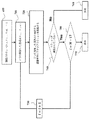
図12は、1つの実施形態による、リアルタイム制御のために、運動学的経路を更に処理して基準軌道を生成する方法のブロック図を示している。ブロック1201において、運動学的経路及び加速度制約1210から初期軌道X0(t)が生成される。ブロック1202は、以下の最適制御問題を解くことによって基準軌道1220を生成する。
FIG. 12 illustrates a block diagram of a method of further processing a kinematic path to generate a reference trajectory for real-time control, according to one embodiment. At
1つの実施形態において、初期推測は、運動学的経路Xk(t)から生成し、車両動態(1)を変換することができる。別の実施形態において、境界条件X(tn)=Xf及びX(0)=X0は、満たすのが困難である場合がある。以下の最適化問題を考慮することが有利である。 In one embodiment, the initial guess can be generated from the kinematic path X k (t) to transform the vehicle dynamics (1). In another embodiment, the boundary conditions X(t n )=X f and X(0)=X 0 may be difficult to meet. It is advantageous to consider the following optimization problem.
別の実施形態において、運動学的経路の計算中に得られるtn、すなわち、車両がX0からXfまで運動する時間は、満たすには過度に厳格であり、したがって、上述の最適化問題の実現可能性を危うくする場合がある。tn〜(1+α)tnを0<α<∞で緩和することによって、初期軌道と同等に運動学的経路を生成することができる。 In another embodiment, the t n obtained during the calculation of the kinematic path, ie the time the vehicle moves from X 0 to X f , is too rigid to satisfy, and thus the optimization problem described above. May compromise the feasibility of. By relaxing t n to (1+α)t n with 0<α<∞, it is possible to generate a kinematic path equivalent to the initial trajectory.
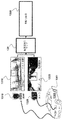
図13は、1つの実施形態によるシステムの概略図を示している。システムは、自動化駐車1350を実行するように構成されたプロセッサ1302を備える車両1301を備える。車両は、LIDAR1310及び/又はカメラ1320等の少なくとも1つのセンサーも備える。LIDARセンサー1310は、低分解能の第1のセンサーであり、カメラ1320は、高分解能の第2のセンサーである。センサー1310及び/又は1320は、プロセッサ1302に動作的に接続されるとともに、駐車空間の少なくとも一部のジオメトリを示す情報を検知するように構成される。この情報を用いて、プロセッサ1302は、駐車空間のマップ130を求め、及び/又は更新する。そのために、プロセッサ1302は、マップ130を用いて自動化駐車1350を実行する。
FIG. 13 shows a schematic diagram of a system according to one embodiment. The system comprises a
図14は、いくつかの実施形態による自動化駐車システム1400のブロック図を示している。システム1400は、車両1301の内部に実装することができる。付加的又は代替的に、システム1400は、車両1301に通信可能に接続することができる。
FIG. 14 illustrates a block diagram of an
システム1400は、カメラ1410、慣性測定ユニット(IMU)1430、プロセッサ1450、メモリ1460、送受信機1470、及びディスプレイ/スクリーン1480のうちの1つ又は組み合わせを備えることができる。これらは、接続1420を通じて他の構成要素に動作的に結合することができる。接続1420は、バス、ライン、ファイバー、リンク又はそれらの組み合わせを含むことができる。
送受信機1470は、例えば、1つ以上のタイプの無線通信ネットワークを通じて1つ以上の信号を送信することを可能にする送信機と、1つ以上のタイプの無線通信ネットワークを通じて送信された1つ以上の信号を受信する受信機とを備えることができる。送受信機1470は、様々な技術に基づいて無線ネットワークとの通信を可能にすることができる。これらの技術は、標準規格のIEEE802.11ファミリーに基づくことができるフェムトセル、Wi−Fiネットワーク又は無線ローカルエリアネットワーク(WLAN)、標準規格のIEEE802.15xファミリーに基づくBluetooth(登録商標)、近距離場通信(NFC)、ネットワーク等の無線パーソナルエリアネットワーク(WPAN)、及び/又はLTE、WiMAX等の無線ワイドエリアネットワーク(WWAN)等であるが、これらに限定されるものではない。システム1400は、有線ネットワークを通じて通信する1つ以上のポートを備えることもできる。
いくつかの実施形態では、システム1400は、CCDセンサー若しくはCMOSセンサー、レーザー及び/又はカメラ等の画像センサー1410を備えることができる。この画像センサーは、以下では「センサー1410」と呼ばれる。例えば、センサー1410は、光画像を電子画像又はデジタル画像に変換することができ、取得された画像をプロセッサ1450に送信することができる。付加的又は代替的に、センサー1410は、シーン内のターゲット物体から反射された光を検知し、捕捉された光の強度をプロセッサ1450にサブミットすることができる。
In some embodiments, the
例えば、センサー1410は、「カラー情報」を提供するカラーカメラ又はグレースケールカメラを含むことができる。「カラー情報」という用語は、本明細書において用いられるとき、カラー情報及び/又はグレースケール情報を指す。一般に、カラー画像又はカラー情報は、本明細書において用いられるとき、1〜N個のチャネルを含むものとみなすことができる。ここで、Nは、画像を記憶するのに用いられている色空間に依存する或る整数である。例えば、RGB画像は、3つのチャネルを含み、赤情報、青情報及び緑情報についてそれぞれ1つのチャネルを有する。
For example, the
例えば、センサー1410は、「深度情報」を提供する深度センサーを含むことができる。深度情報は、深度センサーを用いて様々な方法で取得することができる。「深度センサー」という用語は、深度情報を単独で及び/又は他のいくつかのカメラと併せて取得するのに用いることができる機能ユニットを指すのに用いられる。例えば、いくつかの実施形態では、深度センサー及び光カメラは、センサー1410の一部分とすることができる。例えば、いくつかの実施形態では、センサー1410はRGBDカメラを備える。このRGBDカメラは、カラー(RGB)画像に加えて、深度センサーが有効にされているときはピクセルごとの深度(D)情報を捕捉することができる。
For example, the
別の例として、いくつかの実施形態では、センサー1410は、3D飛行時間(3DTOF)カメラを備えることができる。3DTOFカメラを用いた実施形態では、深度センサーは、3DTOFカメラに結合されたストロボライトの形態を取ることができる。このストロボライトは、シーン内の物体を照明することができ、反射された光は、センサー1410内のCCD/CMOSセンサーが捕捉することができる。深度情報は、光パルスが物体に進んでセンサーに戻って来るまでに要する時間を測定することによって取得することができる。
As another example, in some embodiments the
更なる例として、深度センサーは、センサー1410に結合された光源の形態を取ることができる。1つの実施形態では、この光源は、1つ以上の狭い光の帯を含むことができる構造化された光パターン又はテクスチャー付けされた光パターンをシーン内の物体に投射する。深度情報は、物体の表面形状によって引き起こされる投射パターンの幾何学的歪みを利用することによって取得される。1つの実施形態は、赤外線構造化光プロジェクターと、RGBカメラにレジスタリングされた赤外線カメラとの組み合わせ等のステレオセンサーから深度情報を求める。
As a further example, the depth sensor can take the form of a light source coupled to the
いくつかの実施形態では、センサー1410は立体カメラを備える。例えば、深度センサーは、2つ以上のカメラを用いてシーンの深度情報を取得することができる受動ステレオビジョンセンサーの一部分を成すことができる。捕捉されたシーンにおける双方のカメラに共通の点のピクセル座標を、カメラ姿勢情報及び/又は三角測量技法とともに用いて、ピクセルごとの深度情報を取得することができる。
In some embodiments,
いくつかの実施形態では、システム1400は、デュアルフロントカメラ及び/又は前面カメラ及び背面カメラ等の複数のセンサー1410に動作的に接続することができ、これらの複数のセンサーは、様々なセンサーを組み込むこともできる。いくつかの実施形態では、センサー1410は、静止画像及びビデオ画像の双方を捕捉することができる。いくつかの実施形態では、センサー1410は、例えば、30フレーム毎秒(fps)で画像を捕捉することが可能なRGBD又は立体ビデオカメラを備えることができる。1つの実施形態では、センサー1410によって捕捉された画像は、生の未圧縮フォーマットとすることができ、処理及び/又はメモリ1460への記憶の前に圧縮することができる。いくつかの実施形態では、画像圧縮は、プロセッサ1450によって可逆圧縮技法又は非可逆圧縮技法を用いて実行することができる。
In some embodiments, the
いくつかの実施形態では、プロセッサ1450は、IMU1430から入力を受信することもできる。他の実施形態では、IMU1430は、3軸加速度計(複数の場合もある)、3軸ジャイロスコープ(複数の場合もある)、及び/又は磁気計(複数の場合もある)を備えることができる。IMU1430は、速度、方位、及び/又は他の位置関連情報をプロセッサ1450に提供することができる。いくつかの実施形態では、IMU1430は、測定された情報を、センサー1410による各画像フレームの捕捉と同期して出力することができる。いくつかの実施形態では、IMU1430の出力は、プロセッサ1450がセンサー測定値を融合し及び/又は融合された測定値を更に処理するのに部分的に用いられる。
In some embodiments, processor 1450 may also receive input from
また、システム1400は、カラー画像及び/又は深度画像等の画像をレンダリングするスクリーン又はディスプレイ1480を備えることができる。いくつかの実施形態では、ディスプレイ1480は、センサー1410によって捕捉されたライブ画像、融合画像、拡張現実(AR)画像、グラフィカルユーザーインターフェース(GUI)、及び他の番組(program:プログラム)出力を表示するのに用いることができる。いくつかの実施形態では、ディスプレイ1480は、ユーザーが、仮想キーボード、アイコン、メニュー、又は他のGUI、ユーザージェスチャー及び/又はスタイラス及び他の筆記用具等の入力デバイスの或る組み合わせを介してデータを入力することを可能にするタッチスクリーンを備えることができ及び/又はこのようなタッチスクリーンとともに収容することができる。いくつかの実施形態では、ディスプレイ1480は、液晶ディスプレイ(LCD)又は有機LED(OLED)ディスプレイ等の発光ダイオード(LED)ディスプレイを用いて実施することができる。他の実施形態では、ディスプレイ1480は、ウェアラブルディスプレイとすることができる。いくつかの実施形態では、融合の結果をディスプレイ1480にレンダリングすることもできるし、システム1400の内部又は外部に存在することができる異なるアプリケーションにサブミットすることもできる。
The
例示的なシステム1400は、図示した機能ブロックのうちの1つ以上の追加、組み合わせ、又は省略等によって、本開示と整合性を有するように様々な方法で変更することもできる。例えば、いくつかの構成では、システム1400は、IMU1430又は送受信機1470を備えていない。さらに、いくつかの特定の例示の実施態様では、システム1400は、周辺光センサー、マイクロフォン、音響センサー、超音波センサー、レーザーレンジファインダー等の様々な他のセンサー(図示せず)を備える。いくつかの実施形態では、システム1400のいくつかの部分は、1つ以上のチップセット等の形態を取る。
The
プロセッサ1450は、ハードウェア、ファームウェア及びソフトウェアの組み合わせを用いて実現することができる。プロセッサ1450は、センサー融合及び/又は融合した測定値を更に処理するための方法に関連付けられる計算手順又はプロセスの少なくとも一部を実行するように構成可能な1つ以上の回路を表すことができる。プロセッサ1450は、メモリ1460から命令及び/又はデータを引き出す。プロセッサ1450は、1つ以上の特定用途向け集積回路(ASIC)、中央及び/又はグラフィカル処理ユニット(CPU及び/又はGPU)、デジタルシグナルプロセッサ(DSP)、デジタル信号処理デバイス(DSPD)、プログラマブル論理デバイス(PLD)、フィールドプログラマブルゲートアレイ(FPGA)、コントローラー、マイクロコントローラー、マイクロプロセッサ、埋め込みプロセッサコア、電子デバイス、本明細書において記述される機能を実行するように設計された他の電子ユニット、又はその組み合わせを用いて実現することができる。 Processor 1450 can be implemented using a combination of hardware, firmware and software. Processor 1450 may represent one or more circuits configurable to perform at least some of the computational procedures or processes associated with sensor fusion and/or a method for further processing the fused measurements. Processor 1450 retrieves instructions and/or data from memory 1460. Processor 1450 includes one or more application specific integrated circuits (ASICs), central and/or graphical processing units (CPUs and/or GPUs), digital signal processors (DSPs), digital signal processing devices (DSPDs), programmable logic devices. (PLD), field programmable gate array (FPGA), controller, microcontroller, microprocessor, embedded processor core, electronic device, other electronic unit designed to perform the functions described herein, or the like. It can be realized by using a combination.
メモリ1460は、プロセッサ1450の内部に、及び/又はプロセッサ1450の外部に実装することができる。本明細書において使用されるときに、「メモリ」という用語は、任意のタイプの長期、短期、揮発性、不揮発性又は他のメモリを指しており、任意の特定のタイプのメモリ若しくはメモリの数、又はメモリが記憶される物理媒体のタイプに制限されるべきではない。いくつかの実施形態では、メモリ1460は、自動化駐車を容易にするプログラムコードを保持する。 Memory 1460 may be implemented within processor 1450 and/or external to processor 1450. The term "memory" as used herein refers to any type of long-term, short-term, volatile, non-volatile or other memory, and any particular type of memory or number of memories. , Or the type of physical medium on which the memory is stored should not be limited. In some embodiments, memory 1460 holds program code that facilitates automated parking.
例えば、メモリ1460は、静止画像、深度情報、ビデオフレーム、プログラム結果、並びにIMU1430及び他のセンサーによって提供されるデータ等のセンサーの測定値を記憶することができる。メモリ1460は、車両のジオメトリ、駐車空間のマップ、車両の運動学的モデル、及び車両の動的モデルを記憶するメモリを格納することができる。一般に、メモリ1460は、任意のデータ記憶機構を表すことができる。メモリ1460は、例えば、一次メモリ及び/又は二次メモリを含むことができる。一次メモリは、例えば、ランダムアクセスメモリ、リードオンリーメモリ等を含むことができる。図14においてプロセッサ1450とは別であるように示されるが、一次メモリの全て若しくは一部をプロセッサ1450内に設けることができるか、又はそうでなくても、プロセッサ1450と同一の場所に配置し、及び/又はプロセッサ1450に結合することができることは理解されたい。
For example, memory 1460 may store sensor measurements such as still images, depth information, video frames, program results, and data provided by
二次メモリは、例えば、一次メモリと同じ、又は類似のタイプのメモリ、及び/又は例えば、フラッシュ/USBメモリドライブ、メモリカードドライブ、ディスクドライブ、光ディスクドライブ、テープドライブ、ソリッドステートドライブ、ハイブリッドドライブ等の1つ以上のデータ記憶デバイス又はシステムを含むことができる。或る特定の実施態様において、二次メモリは、取外し可能な媒体ドライブ(図示せず)内の非一時的コンピューター可読媒体に動作的に収容可能であるか、又は別の方法で、動作的に構成可能とすることができる。いくつかの実施形態において、非一時的コンピューター可読媒体は、メモリ1460及び/又はプロセッサ1450の一部を形成する。 The secondary memory is, for example, a memory of the same type as or similar to the primary memory, and/or for example, a flash/USB memory drive, a memory card drive, a disk drive, an optical disk drive, a tape drive, a solid state drive, a hybrid drive, etc. May include one or more data storage devices or systems. In certain embodiments, the secondary memory is operatively storable on a non-transitory computer readable medium in a removable media drive (not shown) or otherwise operatively. It can be configurable. In some embodiments, a non-transitory computer readable medium forms part of memory 1460 and/or processor 1450.
本発明の上記で説明した実施形態は、多数の方法のうちの任意のもので実施することができる。例えば、実施形態は、ハードウェア、ソフトウェア又はそれらの組み合わせを用いて実施することができる。ソフトウェアで実施される場合、ソフトウェアコードは、単一のコンピューターに設けられるのか又は複数のコンピューター間に分散されるのかにかかわらず、任意の適したプロセッサ又はプロセッサの集合体において実行することができる。そのようなプロセッサは、1つ以上のプロセッサを集積回路部品に有する集積回路として実装することができる。ただし、プロセッサは、任意の適したフォーマットの回路類を用いて実装することができる。 The above-described embodiments of the present invention can be implemented in any of numerous ways. For example, the embodiments can be implemented using hardware, software, or a combination thereof. If implemented in software, the software code may execute on any suitable processor or collection of processors, whether implemented on a single computer or distributed among multiple computers. Such a processor may be implemented as an integrated circuit having one or more processors in the integrated circuit component. However, the processor may be implemented with circuitry of any suitable format.
また、本発明の実施形態は、例が提供された方法として実施することができる。この方法の一部として実行される動作は、任意の適切な方法で順序付けすることができる。したがって、動作が示したものと異なる順序で実行される実施形態を構築することができ、これには、例示の実施形態では一連の動作として示されたにもかかわらず、いくつかの動作を同時に実行することを含めることもできる。 Embodiments of the invention may also be implemented as methods in the examples provided. The acts performed as part of this method may be ordered in any suitable way. Thus, an embodiment can be constructed in which the operations are performed in a different order than that shown, in which some operations are performed simultaneously, even though they are shown as a series of operations in the exemplary embodiment. It can also include performing.
請求項の要素を修飾する、特許請求の範囲における「第1」、「第2」等の序数の使用は、それ自体で、1つの請求項の要素の別の請求項の要素に対する優先順位も、優位性も、順序も暗示するものでもなければ、方法の動作が実行される時間的な順序も暗示するものでもなく、請求項の要素を区別するために、単に、或る特定の名称を有する1つの請求項の要素を、同じ(序数の用語の使用を除く)名称を有する別の要素と区別するラベルとして用いられているにすぎない。 The use of ordinal numbers such as "first", "second", etc. in a claim to modify a claim element is itself such that a claim element has priority over another claim element. , Neither do they imply superiority, nor the order, nor the temporal order in which the acts of the method are performed, and to distinguish claim elements simply use certain names. It is only used as a label to distinguish one claimed element from another element that has the same name (except for the use of ordinal terms).
Claims (17)
前記車両のジオメトリ及び前記駐車空間のマップを用いて、前記車両の初期状態を、通過点のセットを通じて駐車車両の目標状態と接続する衝突を伴わない幾何学的経路を求めることであって、各通過点は、前記車両の位置及び方位を規定することと、
前記車両の運動学的モデルを用いて、運動学的エッジと接続された複数のノードを有する運動学的グラフを形成する運動学的サブグラフのセットを求めることであって、各運動学的サブグラフは、前記幾何学的経路の近傍の通過点の対を接続し、各ノードは、前記車両の状態を規定し、2つのノードを接続する各運動学的エッジは、前記車両の運動学的特性に従って前記2つのノードを接続する衝突を伴わない運動学的経路を規定することと、
前記運動学的グラフから、前記車両の初期状態に対応する初期ノードを、中間ノードのセットを通じて、前記車両の目標状態に対応する目標ノードと接続する運動学的経路を選択することと、
前記車両の動的モデルを用いて、前記運動学的経路を時間の関数として追跡する基準軌道を求めることと、
前記基準軌道に従って前記車両の運動を制御することと、
を含み、
前記幾何学的経路を前記求めることは、
前記初期ノードを、衝突を伴わないノードのセットを通じて前記目標ノードと接続する幾何学的グラフを構築することであって、前記幾何学的グラフにおけるノードの各対は、前記車両及び前記駐車空間のジオメトリのみを用いて求められた衝突を伴わないエッジで接続されることと、
前記幾何学的経路の前記通過点のセットを形成する前記幾何学的グラフからノードのセットを選択することと、
を含み、
前記駐車空間の状態空間内の点をサンプリングして、サンプリングされた状態を生成することと、
前記幾何学的グラフのノードの全ての状態が前記サンプリングされた状態の到達不可能エリア内にある場合、前記サンプリングされた状態を拒絶することと、
そうではない場合、
前記サンプリングされた状態に最も近い状態を有する前記幾何学的グラフの最近傍のノードを求めることと、
前記サンプリングされた状態のノードを前記幾何学的グラフに追加すること、及び前記追加されたノードを、エッジが衝突を伴わない場合に前記エッジを介して前記最近傍のノードと接続することと、
前記サンプリングすること、前記拒絶すること、前記求めること、及び前記追加することを、前記初期ノードが前記目標ノードに接続されるまで繰り返すことと、
を更に含む、方法。 A method of parking a vehicle in a parking space, the method being coupled to a memory storing a geometry of the vehicle, a map of the parking space, a kinematic model of the vehicle, and a dynamic model of the vehicle. used the processor, wherein the processor is coupled to the storage instructions for performing the method, the store instruction, when executed by the processor, to perform at least some steps of the method, the at least some The steps of
Determining a geometric path without collisions that connects the initial state of the vehicle with a target state of the parked vehicle through a set of transit points using the geometry of the vehicle and the map of the parking space, each of which: The passing point defines the position and direction of the vehicle,
Determining, using the kinematic model of the vehicle, a set of kinematic subgraphs forming a kinematic graph having a plurality of nodes connected to kinematic edges, each kinematic subgraph being , Connecting a pair of passing points in the vicinity of the geometrical path, each node defining the state of the vehicle, and each kinematic edge connecting two nodes being in accordance with the kinematic characteristics of the vehicle. Defining a collision-free kinematic path connecting the two nodes;
From the kinematic graph, selecting a kinematic path connecting an initial node corresponding to the initial state of the vehicle through a set of intermediate nodes with a target node corresponding to the target state of the vehicle;
Determining a reference trajectory that tracks the kinematic path as a function of time using the dynamic model of the vehicle;
Controlling the movement of the vehicle according to the reference trajectory,
Only including,
Determining the geometrical path
Constructing a geometrical graph connecting the initial node with the target node through a set of nodes without collision, each pair of nodes in the geometrical graph comprising: Connected by edges without collisions determined using geometry only,
Selecting a set of nodes from the geometric graph forming the set of transit points of the geometric path;
Including,
Sampling points in the state space of the parking space to generate sampled states;
Rejecting the sampled state if all states of the nodes of the geometric graph are within an unreachable area of the sampled state;
If not,
Finding the nearest node of the geometric graph that has a state that is closest to the sampled state;
Adding the sampled state node to the geometric graph, and connecting the added node with the nearest node via the edge if the edge does not involve a collision;
Repeating the sampling, the rejecting, the seeking, and the adding until the initial node is connected to the target node;
The method further comprising :
を更に含む、請求項1に記載の方法。 Iteratively growing the kinematic graph from a set of seeds corresponding to the set of transit points,
The method of claim 1, further comprising:
メモリから前記車両のジオメトリを選択することであって、前記センサー及び前記メモリは、前記プロセッサに動作的に接続されることと、
を更に含む、請求項1に記載の方法。 Determining the geometry of at least a portion of the parking space using at least one sensor of the vehicle;
Selecting a geometry of the vehicle from a memory, the sensor and the memory operatively connected to the processor;
The method of claim 1, further comprising:
前記初期ノードについて求められた前記最小コストを有する、前記初期ノードを前記目標ノードと接続するノードのセットを選択して、前記幾何学的経路の前記通過点のセットを形成することと、
を更に含む、請求項1に記載の方法。 Determining, for each of the non-leaf nodes and the initial node of the geometric graph, the minimum cost to reach the target node;
Selecting a set of nodes connecting the initial node with the target node having the minimum cost determined for the initial node to form the set of transit points of the geometric path;
Further comprising the method of claim 1.
前記幾何学的グラフからの前記除去された前記葉ノードを接続する前記エッジを除去することと、
を更に含む、請求項5に記載の方法。 And that the initial node and the target node except leaf nodes, removed from the geometric graph,
And removing the edges connecting the removed the leaf node from the geometric graph,
The method of claim 5 , further comprising:
前記車両のジオメトリ及び前記駐車空間のマップを用いて、前記車両の初期状態を、通過点のセットを通じて駐車車両の目標状態と接続する衝突を伴わない幾何学的経路を求めることであって、各通過点は、前記車両の位置及び方位を規定することと、
前記車両の運動学的モデルを用いて、運動学的エッジと接続された複数のノードを有する運動学的グラフを形成する運動学的サブグラフのセットを求めることであって、各運動学的サブグラフは、前記幾何学的経路の近傍の通過点の対を接続し、各ノードは、前記車両の状態を規定し、2つのノードを接続する各運動学的エッジは、前記車両の運動学的特性に従って前記2つのノードを接続する衝突を伴わない運動学的経路を規定することと、
前記運動学的グラフから、前記車両の初期状態に対応する初期ノードを、中間ノードのセットを通じて、前記車両の目標状態に対応する目標ノードと接続する運動学的経路を選択することと、
前記車両の動的モデルを用いて、前記運動学的経路を時間の関数として追跡する基準軌道を求めることと、
前記基準軌道に従って前記車両の運動を制御することと、
を含み、
前記運動学的グラフを前記求めることは、
前記通過点のセットに近接する前記駐車空間をサンプリングして、サンプリングされた状態を生成することと、
前記サンプリングされた状態を、ツリーを更新するために、前記運動学的エッジが衝突を伴わないものである場合に前記運動学的エッジを用いて少なくとも1つの通過点から開始する少なくとも1つのツリーと接続することと、
終了条件が満たされるまで前記サンプリングすること及び前記接続することを繰り返すことと、
を含み、前記終了条件は、前記接続された幾何学的グラフの前記形成、前記運動学的グラフ上で前記初期ノードと前記目標ノードとを接続する経路の数が閾値を超えること、近傍の通過点のツリーに接続するノードの数、のうちの1つ又は組み合わせを含む、方法。 A method of parking a vehicle in a parking space, the method being coupled to a memory storing a geometry of the vehicle, a map of the parking space, a kinematic model of the vehicle, and a dynamic model of the vehicle. used the processor, wherein the processor is coupled to the storage instructions for performing the method, the store instruction, when executed by the processor, to perform at least some steps of the method, the at least some The steps of
Determining a geometric path without collisions that connects the initial state of the vehicle with a target state of the parked vehicle through a set of transit points using the geometry of the vehicle and the map of the parking space, each of which: The passing point defines the position and direction of the vehicle,
Determining, using the kinematic model of the vehicle, a set of kinematic subgraphs forming a kinematic graph having a plurality of nodes connected to kinematic edges, each kinematic subgraph being , Connecting a pair of passing points in the vicinity of the geometrical path, each node defining the state of the vehicle, and each kinematic edge connecting two nodes being in accordance with the kinematic characteristics of the vehicle. Defining a collision-free kinematic path connecting the two nodes;
From the kinematic graph, selecting a kinematic path connecting an initial node corresponding to the initial state of the vehicle through a set of intermediate nodes with a target node corresponding to the target state of the vehicle;
Determining a reference trajectory that tracks the kinematic path as a function of time using the dynamic model of the vehicle;
Controlling the movement of the vehicle according to the reference trajectory,
Only including,
Determining the kinematic graph
Sampling the parking space proximate the set of transit points to generate a sampled state;
At least one tree starting from at least one transit point with the kinematic edge when the kinematic edge is collision free to update the tree; Connecting
Repeating the sampling and connecting until a termination condition is met;
The termination condition includes the formation of the connected geometric graph, the number of paths connecting the initial node and the target node on the kinematic graph exceeding a threshold value, and passage of a neighborhood. A method comprising one or a combination of the number of nodes connected to a tree of points .
サブグラフSGiを、衝突を伴わないノード及び運動学的エッジのセットを通じて前記通過点Xi+1に接続するサブグラフSGi+1を形成することであって、SGiは、2つの隣接した通過点Xi−1、Xiについての先行する反復中に求められた前記サブグラフであることと、
0≦i≦M−1について前記選択すること及び前記形成することを繰り返すことと、
を更に含む、請求項7に記載の方法。 The set of passing points X0,. . . , XM, selecting two adjacent transit points Xi, Xi+1;
Forming a subgraph SGi+1 connecting the subgraph SGi to said passing point Xi+1 through a set of nodes and kinematic edges without collision, SGi for two adjacent passing points Xi-1, Xi. Being the subgraph determined during the previous iteration,
Repeating the selecting and forming for 0≦i≦M−1;
The method of claim 7 , further comprising:
通過点Xi、Xi+1に近接する前記車両の運動学的モデルの状態空間から新たな状態Xをバイアスしてサンプリングすることと、
前記車両が前記新たな状態から前記初期ツリー及び前記目標ツリーにおける状態への衝突を伴わない運動学的経路を辿ることができる場合、前記初期ツリー及び前記目標ツリーのうちの少なくとも一方に前記新たな状態Xを追加することと、
前記新たな状態Xが前記初期ツリー及び前記目標ツリーの双方に追加されるまで、前記サンプリングすること及び前記追加することを繰り返すことと、
を更に含む、請求項9に記載の方法。 Initializing the subgraph with an initial tree and a target tree, the initial tree comprising geometrical transit points {X0,. . . , Xi} including the sub-graph SGi including a node corresponding to the passing point Xi+1, and the target tree including the node corresponding to the passing point Xi+1.
Biasing and sampling a new state X from the state space of the kinematic model of the vehicle close to the passing points Xi, Xi+1;
If the vehicle can follow a collision-free kinematic path from the new state to the states in the initial tree and the target tree, then the new tree is added to at least one of the initial tree and the target tree. Adding state X,
Repeating the sampling and the adding until the new state X is added to both the initial tree and the target tree;
10. The method of claim 9 , further comprising:
前記確率分布関数P(X|Xi,Xi+1)に従って前記状態空間から前記新たな状態Xをサンプリングすることと、
前記サンプリングされた状態が衝突を伴わないものになるまで前記サンプリングすることを繰り返すことと、
を更に含む、請求項10に記載の方法。 Constructing a probability distribution function P(X|Xi, Xi+1) according to the passing points Xi, Xi+1 and the geometry of the vehicle and the parking space;
Sampling the new state X from the state space according to the probability distribution function P(X|Xi, Xi+1);
Repeating the sampling until the sampled state is collision free;
The method of claim 10 , further comprising:
前記車両のジオメトリ及び前記駐車空間のマップを用いて、前記車両の初期状態を、通過点のセットを通じて駐車車両の目標状態と接続する衝突を伴わない幾何学的経路を求めることであって、各通過点は、前記車両の位置及び方位を規定することと、
前記車両の運動学的モデルを用いて、運動学的エッジと接続された複数のノードを有する運動学的グラフを形成する運動学的サブグラフのセットを求めることであって、各運動学的サブグラフは、前記幾何学的経路の近傍の通過点の対を接続し、各ノードは、前記車両の状態を規定し、2つのノードを接続する各運動学的エッジは、前記車両の運動学的特性に従って前記2つのノードを接続する衝突を伴わない運動学的経路を規定することと、
前記運動学的グラフから、前記車両の初期状態に対応する初期ノードを、中間ノードのセットを通じて、前記車両の目標状態に対応する目標ノードと接続する運動学的経路を選択することと、
前記車両の動的モデルを用いて、前記運動学的経路を時間の関数として追跡する基準軌道を求めることと、
前記基準軌道に従って前記車両の運動を制御することと、
を含み、
前記運動学的グラフの各ノードの最適コストを求めることであって、ノードの前記最適コストは、前記車両を、前記ノードから前記運動学的グラフのエッジを通じて前記目標ノードに運動させる最良推定コストを表すことと、
方策反復によって、運動学的通過点と前記初期状態を前記目標状態と接続する関連付けられたエッジとのセットによって表される初期運動学的経路を求めることと、
を更に含む、方法。 A method of parking a vehicle in a parking space, the method coupled to a memory storing a geometry of the vehicle, a map of the parking space, a kinematic model of the vehicle, and a dynamic model of the vehicle. used the processor, wherein the processor is coupled to the storage instructions for performing the method, the store instruction, when executed by the processor, to perform at least some steps of the method, the at least some The steps of
Determining a geometric path without collisions that connects the initial state of the vehicle with a target state of the parked vehicle through a set of transit points using the geometry of the vehicle and the map of the parking space, each of which: The passing point defines the position and direction of the vehicle,
Determining, using the kinematic model of the vehicle, a set of kinematic subgraphs forming a kinematic graph having a plurality of nodes connected to kinematic edges, each kinematic subgraph being , Connecting a pair of passing points in the vicinity of the geometrical path, each node defining the state of the vehicle, and each kinematic edge connecting two nodes being in accordance with the kinematic characteristics of the vehicle. Defining a collision-free kinematic path connecting the two nodes;
From the kinematic graph, selecting a kinematic path connecting an initial node corresponding to the initial state of the vehicle through a set of intermediate nodes with a target node corresponding to the target state of the vehicle;
Determining a reference trajectory that tracks the kinematic path as a function of time using the dynamic model of the vehicle;
Controlling the movement of the vehicle according to the reference trajectory,
Only including,
Determining an optimal cost for each node of the kinematic graph, the optimal cost of the node being the best estimated cost of moving the vehicle from the node through the edges of the kinematic graph to the target node. To represent,
Determining an initial kinematic path represented by a set of kinematic transit points and associated edges connecting the initial state with the target state by policy iteration;
The method further comprising :
次の状態と前記現在状態との間のエッジE(Xc,Xn)が前記現在状態から前記目標状態への最小コストを生成するように、前記現在状態の前記次の状態Xnを求めることと、
前記次の状態Xn及び前記エッジE(Xc,Xn)を、前記初期運動学的経路P0={P0,Xn,E(Xc,Xn)}に追加することと、
前記次の状態が前記目標状態になるまで、前記求めること及び前記追加することを繰り返すことと、
を更に含む、請求項12に記載の方法。 Initializing the initial kinematic path P0 to include the current state Xc as the initial state X0 of the first kinematic transit point;
Determining the next state Xn of the current state such that an edge E(Xc,Xn) between the next state and the current state produces a minimum cost from the current state to the target state;
Adding the next state Xn and the edge E(Xc,Xn) to the initial kinematic path P0={P0,Xn,E(Xc,Xn)};
Repeating the determining and the adding until the next state is the target state;
13. The method of claim 12 , further comprising:
を更に含む、請求項1に記載の方法。 Smoothing the kinematic path by removing intermediate waypoints that are unnecessary to reach a subsequent waypoint in the kinematic path,
The method of claim 1, further comprising:
前記車両のジオメトリ、前記駐車空間のマップ、前記車両の運動学的モデル、及び前記車両の動的モデルを記憶するメモリと、
前記駐車空間の少なくとも一部のジオメトリを示す情報を検知するように動作するセンサーと、
前記メモリに結合されたプロセッサであって、
前記車両のジオメトリ及び前記駐車空間のマップを用いて、前記車両の初期状態を、通過点のセットを通じて駐車車両の目標状態と接続する衝突を伴わない幾何学的経路を求めることであって、各通過点は、前記車両の位置及び方位を規定することと、
前記車両の運動学的モデルを用いて、運動学的エッジと接続された複数のノードを有する運動学的グラフを形成する、前記通過点のセットに対応するシードのセットから成長した運動学的サブグラフのセットを求めることであって、各運動学的サブグラフは、前記幾何学的経路の近傍の通過点の対を接続し、各ノードは、前記車両の状態を規定し、2つのノードを接続する各運動学的エッジは、前記車両の運動学的特性に従って前記2つのノードを接続する衝突を伴わない運動学的経路を規定することと、
前記運動学的グラフから、前記車両の初期状態に対応する初期ノードを、中間ノードのセットを通じて、前記車両の前記目標状態に対応する目標ノードと接続する運動学的経路を選択することと、
前記車両の動的モデルを用いて、前記運動学的経路を時間の関数として追跡する基準軌道を求めることと、
を行うように構成された、プロセッサと、
前記基準軌道に従って前記車両の運動を制御するコントローラーと、
を備え、
前記プロセッサは、
前記駐車空間の状態空間内の点をサンプリングして、サンプリングされた状態を生成することであって、前記サンプリングすることは、前記通過点の前記状態の関数として平均及び共分散を有する前記駐車空間の状態の確率分布を用いてバイアスして実行されることと、
幾何学的グラフのノードの全ての状態が前記サンプリングされた状態の到達不可能エリア内にある場合、前記サンプリングされた状態を拒絶することと、
そうではない場合、
前記サンプリングされた状態に最も近い状態を有する前記幾何学的グラフの最近傍のノードを求めることと、
前記サンプリングされた状態のノードを前記幾何学的グラフに追加すること、及び前記追加されたノードを、エッジが衝突を伴わない場合に前記エッジを介して前記最近傍のノードと接続することと、
前記サンプリングすること、前記拒絶すること、前記求めること、及び前記追加することを、前記初期ノードが前記目標ノードに接続されるまで繰り返すことと、
を行うように構成される、システム。 A system for parking a vehicle in a parking space,
A memory storing the vehicle geometry, the parking space map, the vehicle kinematic model, and the vehicle dynamic model;
A sensor operative to detect information indicative of the geometry of at least a portion of the parking space;
A processor coupled to the memory,
Determining a geometric path without collisions that connects the initial state of the vehicle with a target state of the parked vehicle through a set of transit points using the geometry of the vehicle and the map of the parking space, each of which: The passing point defines the position and direction of the vehicle,
A kinematic subgraph grown from a set of seeds corresponding to the set of transit points forming a kinematic graph having a plurality of nodes connected to kinematic edges using the kinematic model of the vehicle , Each kinematic subgraph connecting a pair of passing points in the vicinity of the geometrical path, each node defining a state of the vehicle and connecting two nodes. Each kinematic edge defining a collision-free kinematic path connecting the two nodes according to the kinematic characteristics of the vehicle;
Selecting from the kinematic graph an kinematic path connecting an initial node corresponding to the initial state of the vehicle through a set of intermediate nodes to a target node corresponding to the target state of the vehicle;
Determining a reference trajectory that tracks the kinematic path as a function of time using the dynamic model of the vehicle;
A processor configured to
A controller for controlling the movement of the vehicle according to the reference trajectory,
Equipped with
The processor is
Sampling a point in the state space of the parking space to produce a sampled state, the sampling comprising the mean and covariance as a function of the state of the passing point. Being biased using the probability distribution of the state of
Rejecting the sampled state if all states of the nodes of the geometric graph are within the unreachable area of the sampled state;
If not,
Finding the nearest node of the geometric graph that has a state that is closest to the sampled state;
Adding the sampled state node to the geometric graph, and connecting the added node with the nearest node via the edge if the edge does not involve a collision;
Repeating the sampling, the rejecting, the seeking, and the adding until the initial node is connected to the target node;
A system configured to perform .
Applications Claiming Priority (3)
| Application Number | Priority Date | Filing Date | Title |
|---|---|---|---|
| US15/402,353 US9969386B1 (en) | 2017-01-10 | 2017-01-10 | Vehicle automated parking system and method |
| US15/402,353 | 2017-01-10 | ||
| PCT/JP2017/043380 WO2018131322A1 (en) | 2017-01-10 | 2017-11-28 | System, method and non-transitory computer readable storage medium for parking vehicle |
Publications (2)
| Publication Number | Publication Date |
|---|---|
| JP2019529209A JP2019529209A (en) | 2019-10-17 |
| JP6749480B2 true JP6749480B2 (en) | 2020-09-02 |
Family
ID=60943078
Family Applications (1)
| Application Number | Title | Priority Date | Filing Date |
|---|---|---|---|
| JP2019512321A Active JP6749480B2 (en) | 2017-01-10 | 2017-11-28 | System, method and non-transitory computer readable storage medium for parking a vehicle |
Country Status (5)
| Country | Link |
|---|---|
| US (1) | US9969386B1 (en) |
| EP (1) | EP3568334B1 (en) |
| JP (1) | JP6749480B2 (en) |
| CN (1) | CN110139794B (en) |
| WO (1) | WO2018131322A1 (en) |
Families Citing this family (54)
| Publication number | Priority date | Publication date | Assignee | Title |
|---|---|---|---|---|
| US10078790B2 (en) * | 2017-02-16 | 2018-09-18 | Honda Motor Co., Ltd. | Systems for generating parking maps and methods thereof |
| JP6759143B2 (en) * | 2017-04-07 | 2020-09-23 | クラリオン株式会社 | Parking support device |
| US10403144B1 (en) * | 2017-05-08 | 2019-09-03 | Open Invention Network Llc | Mobile device transport parking notification and movement tracking |
| US9892642B1 (en) | 2017-05-08 | 2018-02-13 | Open Invention Network Llc | Mobile device transport parking notification and movement tracking |
| US10286904B2 (en) * | 2017-06-12 | 2019-05-14 | GM Global Technology Operations LLC | Autonomous vehicle parking methods and systems |
| US11669104B2 (en) | 2018-05-08 | 2023-06-06 | Continental Automotive Systems, Inc. | User-adjustable trajectories for automated vehicle reversing |
| EP3829958B1 (en) | 2018-07-27 | 2023-10-25 | embotech AG | Method for steering a vehicle and apparatus therefor |
| US11603100B2 (en) * | 2018-08-03 | 2023-03-14 | Continental Autonomous Mobility US, LLC | Automated reversing by following user-selected trajectories and estimating vehicle motion |
| US10809732B2 (en) * | 2018-09-25 | 2020-10-20 | Mitsubishi Electric Research Laboratories, Inc. | Deterministic path planning for controlling vehicle movement |
| EP3864574A1 (en) * | 2018-10-16 | 2021-08-18 | Five AI Limited | Autonomous vehicle planning and prediction |
| CN109466546B (en) * | 2018-11-20 | 2020-09-18 | 广州小鹏汽车科技有限公司 | Automatic parking method and system |
| CN109866761B (en) * | 2019-03-05 | 2020-07-10 | 重庆长安汽车股份有限公司 | Automatic parking path planning method, system and computer readable storage medium |
| US11335191B2 (en) | 2019-04-04 | 2022-05-17 | Geotab Inc. | Intelligent telematics system for defining road networks |
| US11403938B2 (en) | 2019-04-04 | 2022-08-02 | Geotab Inc. | Method for determining traffic metrics of a road network |
| US11341846B2 (en) | 2019-04-04 | 2022-05-24 | Geotab Inc. | Traffic analytics system for defining road networks |
| US10699564B1 (en) | 2019-04-04 | 2020-06-30 | Geotab Inc. | Method for defining intersections using machine learning |
| US11335189B2 (en) | 2019-04-04 | 2022-05-17 | Geotab Inc. | Method for defining road networks |
| US11080568B2 (en) | 2019-04-26 | 2021-08-03 | Samsara Inc. | Object-model based event detection system |
| US10999374B2 (en) | 2019-04-26 | 2021-05-04 | Samsara Inc. | Event detection system |
| US11485353B2 (en) * | 2019-04-30 | 2022-11-01 | Baidu Usa Llc | Segmenting a parking trajectory to control an autonomous driving vehicle to park |
| CN110196602B (en) * | 2019-05-08 | 2020-05-05 | 河海大学 | Rapid underwater robot three-dimensional path planning method for target-oriented centralized optimization |
| CN110111608B (en) * | 2019-05-15 | 2021-06-18 | 南京莱斯信息技术股份有限公司 | Method for identifying moving target operation intention of airport surface on basis of radar track construction |
| US20210064031A1 (en) * | 2019-08-28 | 2021-03-04 | Zenuity Ab | Path planning for autonomous and semi-autonomous vehicles |
| US11537127B2 (en) * | 2019-09-12 | 2022-12-27 | Uatc, Llc | Systems and methods for vehicle motion planning based on uncertainty |
| US11292454B2 (en) * | 2019-09-19 | 2022-04-05 | GM Global Technology Operations LLC | Apparatus and method that determine parking feasibility |
| CN110588273B (en) * | 2019-09-26 | 2021-05-18 | 爱驰汽车有限公司 | Parking assistance method, system, device and storage medium based on road surface detection |
| JP7259698B2 (en) * | 2019-10-17 | 2023-04-18 | トヨタ自動車株式会社 | automatic parking system |
| JP7207262B2 (en) * | 2019-10-29 | 2023-01-18 | トヨタ自動車株式会社 | automatic parking system |
| EP4067821A4 (en) * | 2019-11-29 | 2023-04-05 | Huawei Technologies Co., Ltd. | Path planning method for vehicle and path planning apparatus for vehicle |
| CN112950994B (en) * | 2019-12-10 | 2023-04-07 | 中移物联网有限公司 | Parking information processing method and device and parking space equipment |
| CN113492830B (en) * | 2020-04-08 | 2023-01-06 | 华为技术有限公司 | Vehicle parking path planning method and related equipment |
| CN113561962B (en) * | 2020-04-28 | 2023-11-10 | 广州汽车集团股份有限公司 | Automatic parking path planning method and system and parking control equipment |
| CN111762153A (en) * | 2020-06-02 | 2020-10-13 | 武汉理工大学 | Automatic automobile parking method based on 5G communication mode |
| CN111717282B (en) * | 2020-07-07 | 2021-12-03 | 中国人民解放军国防科技大学 | Man-machine shared driving auxiliary steering method based on model predictive control |
| CN111824131B (en) * | 2020-07-10 | 2021-10-12 | 广州小鹏自动驾驶科技有限公司 | Automatic parking method and vehicle |
| CN111897341A (en) * | 2020-08-05 | 2020-11-06 | 三一专用汽车有限责任公司 | Parking path planning method, parking path planning device and computer-readable storage medium |
| CN111907517B (en) * | 2020-08-07 | 2022-03-01 | 浙江吉利汽车研究院有限公司 | Automatic parking control method and system, vehicle and field end edge cloud system |
| US11884263B2 (en) * | 2020-08-26 | 2024-01-30 | Ford Global Technologies, Llc | Vehicle parking control |
| CN112078594B (en) * | 2020-08-31 | 2023-01-13 | 纵目科技(上海)股份有限公司 | Curvature continuous parking path planning device and method for intelligent parking system |
| US11767035B2 (en) * | 2020-09-04 | 2023-09-26 | Mitsubishi Electric Research Laboratories, Inc. | Autonomous parking with hybrid exploration of parking space |
| CN112078571B (en) * | 2020-09-30 | 2021-07-13 | 安徽江淮汽车集团股份有限公司 | Automatic parking method, automatic parking equipment, storage medium and automatic parking device |
| CN112289023B (en) * | 2020-10-09 | 2024-03-26 | 腾讯科技(深圳)有限公司 | Parking simulation test method and device for automatic driving and related equipment |
| US11702080B2 (en) * | 2020-11-10 | 2023-07-18 | Wejo Limited | System and method for parking tracking using vehicle event data |
| CN114793459A (en) * | 2020-11-24 | 2022-07-26 | 华为技术有限公司 | Estimation of accident risk level of road traffic participants |
| CN112622934B (en) * | 2020-12-25 | 2022-06-24 | 上海商汤临港智能科技有限公司 | Reference track point and reference track generation method, driving method and vehicle |
| DE102021109661B4 (en) * | 2021-04-16 | 2023-03-09 | Avl Software And Functions Gmbh | Method for the geometric representation of a vehicle surface of a vehicle for collision detection |
| EP4086140A1 (en) * | 2021-05-03 | 2022-11-09 | Volvo Truck Corporation | A method for generating a routing map of an area to be used for guiding a vehicle in the area |
| US11860628B2 (en) * | 2021-06-21 | 2024-01-02 | Nvidia Corporation | Parallel processing of vehicle path planning suitable for parking |
| CN113460040B (en) * | 2021-07-23 | 2023-02-03 | 广州小鹏自动驾驶科技有限公司 | Parking path determination method and device, vehicle and storage medium |
| WO2023126049A1 (en) * | 2021-12-28 | 2023-07-06 | Volvo Truck Corporation | A method for controlling a manoeuvre of a vehicle |
| CN116353620A (en) * | 2021-12-28 | 2023-06-30 | 魔门塔(苏州)科技有限公司 | Automatic parking path planning method, device, medium and equipment |
| JP7275406B1 (en) * | 2022-05-11 | 2023-05-17 | 三菱電機株式会社 | Passing point generator |
| CN115092141B (en) * | 2022-06-23 | 2023-07-21 | 哈尔滨工业大学 | Track planning method and equipment applied to lane-changing overtaking of automatic driving vehicle |
| WO2024089595A1 (en) * | 2022-10-28 | 2024-05-02 | C.R.F. Societa' Consortile Per Azioni | Model predictive control-based, low-speed trajectory planning with dynamic obstacle avoidance in unstructured environments |
Family Cites Families (15)
| Publication number | Priority date | Publication date | Assignee | Title |
|---|---|---|---|---|
| US7737866B2 (en) | 2007-09-27 | 2010-06-15 | Automotive Research & Testing Center | Auto-parking device |
| DE102007055391A1 (en) * | 2007-11-20 | 2009-05-28 | Valeo Schalter Und Sensoren Gmbh | Method and device for path planning when parking a vehicle |
| JP5169804B2 (en) * | 2008-12-25 | 2013-03-27 | 株式会社エクォス・リサーチ | Control device |
| KR20120086140A (en) * | 2011-01-25 | 2012-08-02 | 한국전자통신연구원 | Mobile and apparatus for providing auto valet parking service and method thereof |
| DE102012203235A1 (en) * | 2012-03-01 | 2013-09-05 | Robert Bosch Gmbh | Method for automatically performing a driving maneuver |
| JP2014026516A (en) * | 2012-07-27 | 2014-02-06 | Nissan Motor Co Ltd | Target route generation device and target route generation method |
| US8862321B2 (en) | 2012-08-15 | 2014-10-14 | GM Global Technology Operations LLC | Directing vehicle into feasible region for autonomous and semi-autonomous parking |
| CN103810898A (en) * | 2012-11-15 | 2014-05-21 | 深圳市赛格导航科技股份有限公司 | Automatic parking and picking system and method |
| KR102170286B1 (en) * | 2013-08-13 | 2020-10-26 | 현대모비스 주식회사 | Method for controlling steering wheel and System therefor |
| AT514588B1 (en) | 2013-08-29 | 2015-02-15 | Tech Universität Wien | Method for controlling a vehicle |
| CN104260722B (en) * | 2014-09-23 | 2017-06-06 | 北京理工大学 | A kind of automated parking system |
| DE102015201204A1 (en) * | 2015-01-26 | 2016-07-28 | Robert Bosch Gmbh | Valet parking system |
| KR101655290B1 (en) * | 2015-03-18 | 2016-09-08 | 현대오트론 주식회사 | Automatic parking method for vehicle, automatic parking infrastructure device and automatic parking apparatus using the same |
| JP5981010B1 (en) * | 2015-09-30 | 2016-08-31 | 先進モビリティ株式会社 | Vehicle stopping system |
| CN105857306B (en) | 2016-04-14 | 2018-07-10 | 中国科学院合肥物质科学研究院 | A kind of vehicle autonomous parking paths planning method for a variety of scenes of parking |
-
2017
- 2017-01-10 US US15/402,353 patent/US9969386B1/en active Active
- 2017-11-28 CN CN201780077990.0A patent/CN110139794B/en active Active
- 2017-11-28 EP EP17826324.0A patent/EP3568334B1/en active Active
- 2017-11-28 WO PCT/JP2017/043380 patent/WO2018131322A1/en unknown
- 2017-11-28 JP JP2019512321A patent/JP6749480B2/en active Active
Also Published As
| Publication number | Publication date |
|---|---|
| CN110139794B (en) | 2021-07-16 |
| EP3568334B1 (en) | 2022-04-20 |
| EP3568334A1 (en) | 2019-11-20 |
| US9969386B1 (en) | 2018-05-15 |
| CN110139794A (en) | 2019-08-16 |
| JP2019529209A (en) | 2019-10-17 |
| WO2018131322A1 (en) | 2018-07-19 |
Similar Documents
| Publication | Publication Date | Title |
|---|---|---|
| JP6749480B2 (en) | System, method and non-transitory computer readable storage medium for parking a vehicle | |
| JP7090751B2 (en) | Systems and methods to control vehicle movement | |
| EP3283843B1 (en) | Generating 3-dimensional maps of a scene using passive and active measurements | |
| JP7025276B2 (en) | Positioning in urban environment using road markings | |
| JP6771846B2 (en) | Systems and methods for controlling vehicle motion | |
| JP6672212B2 (en) | Information processing apparatus, vehicle, information processing method and program | |
| JP6896103B2 (en) | Systems and methods for controlling vehicle motion | |
| KR20190047595A (en) | A 3d lidar system using a dichroic mirror for autonomous driving vehicles | |
| JP2021504796A (en) | Sensor data segmentation | |
| CN110386142A (en) | Pitch angle calibration method for automatic driving vehicle | |
| US10409283B2 (en) | Vehicle motion control system and method | |
| CN110675307A (en) | Implementation method of 3D sparse point cloud to 2D grid map based on VSLAM | |
| CN110390240B (en) | Lane post-processing in an autonomous vehicle | |
| US11119498B2 (en) | Systems and methods for simulation utilizing a segmentable monolithic mesh | |
| JP2023531831A (en) | Autonomous parking using hybrid search for parking spaces | |
| US20230331217A1 (en) | System and Method for Motion and Path Planning for Trailer-Based Vehicle | |
| JP2020030200A (en) | System and method for locating vehicle using accuracy specification | |
| Hsu et al. | Object detection and recognition by using sensor fusion | |
| US20230278593A1 (en) | System and Method for Parking an Autonomous Ego-Vehicle in a Dynamic Environment of a Parking Area | |
| WO2023199610A1 (en) | System and method for motion and path planning for trailer-based vehicle | |
| WO2023166845A1 (en) | System and method for parking an autonomous ego- vehicle in a dynamic environment of a parking area |
Legal Events
| Date | Code | Title | Description |
|---|---|---|---|
| A521 | Request for written amendment filed |
Free format text: JAPANESE INTERMEDIATE CODE: A523 Effective date: 20190301 |
|
| A621 | Written request for application examination |
Free format text: JAPANESE INTERMEDIATE CODE: A621 Effective date: 20190301 |
|
| A131 | Notification of reasons for refusal |
Free format text: JAPANESE INTERMEDIATE CODE: A131 Effective date: 20191224 |
|
| A521 | Request for written amendment filed |
Free format text: JAPANESE INTERMEDIATE CODE: A523 Effective date: 20200131 |
|
| TRDD | Decision of grant or rejection written | ||
| A01 | Written decision to grant a patent or to grant a registration (utility model) |
Free format text: JAPANESE INTERMEDIATE CODE: A01 Effective date: 20200714 |
|
| A61 | First payment of annual fees (during grant procedure) |
Free format text: JAPANESE INTERMEDIATE CODE: A61 Effective date: 20200811 |
|
| R150 | Certificate of patent or registration of utility model |
Ref document number: 6749480 Country of ref document: JP Free format text: JAPANESE INTERMEDIATE CODE: R150 |
|
| R250 | Receipt of annual fees |
Free format text: JAPANESE INTERMEDIATE CODE: R250 |