JP6748985B2 - Retroreflective sheeting - Google Patents
Retroreflective sheeting Download PDFInfo
- Publication number
- JP6748985B2 JP6748985B2 JP2015147941A JP2015147941A JP6748985B2 JP 6748985 B2 JP6748985 B2 JP 6748985B2 JP 2015147941 A JP2015147941 A JP 2015147941A JP 2015147941 A JP2015147941 A JP 2015147941A JP 6748985 B2 JP6748985 B2 JP 6748985B2
- Authority
- JP
- Japan
- Prior art keywords
- retroreflective
- layer
- holding body
- recess
- body portion
- Prior art date
- Legal status (The legal status is an assumption and is not a legal conclusion. Google has not performed a legal analysis and makes no representation as to the accuracy of the status listed.)
- Active
Links
Images


Description
本発明は再帰反射シートに関する。 The present invention relates to a retroreflective sheet.
従来から、入射した光を光源に向かって反射する再帰反射シートが知られており、交通標識、案内標識、車両用のナンバープレート、広告看板、車線分離標、視線誘導標などに広く利用されている。 Conventionally, a retroreflective sheet that reflects incident light toward a light source is known, and is widely used for traffic signs, guide signs, vehicle license plates, advertising signs, lane separators, line-of-sight guides, and the like. There is.
このような再帰反射シートとして、例えば下記特許文献1が提案されている。下記特許文献1の再帰反射シートは、いわゆるカプセルタイプのプリズム型再帰反射シートと呼ばれるものであり、再帰反射シートの表面側から表面保護層、再帰反射素子層、結合材層の順序で、当該各層が積層される。
As such a retroreflective sheet, for example, the following
結合材層には、再帰反射素子層の再帰反射素子面と結合する結合部が部分的に形成されており、結合材層のうち結合部以外の部分は、再帰反射素子面と離間している。この結合部によって再帰反射素子層と結合材層との間には空気層が形成されている。 The bonding material layer is partially formed with a bonding portion that is bonded to the retroreflective element surface of the retroreflective element layer, and the portion of the bonding material layer other than the bonding portion is separated from the retroreflective element surface. .. An air layer is formed between the retroreflective element layer and the bonding material layer by this bonding portion.
しかしながら、上記特許文献1の再帰反射シートでは結合部が他の部分に比べて硬くなる傾向にあるため、当該再帰反射シートを折り曲げると隣り合う結合部間の部位が屈曲し易い。そのため、再帰反射シートを折り曲げて曲面に設ける場合、隣り合う結合部間の部位が屈曲することにより、当該屈曲部位を基準として隣接する再帰反射素子同士が衝突するので十分に屈曲せず、曲面に追従し難いという懸念があった。また、再帰反射素子同士の衝突により、再帰反射素子が変形する場合や損傷する場合などの事態が生じうるため、再帰反射シートの反射性能が低減する懸念もあった。
However, in the retroreflective sheet of
そこで、本発明は、反射性能を低減することなく、曲面追従性を向上し得る再帰反射シートを提供することにある。 Then, this invention is providing the retroreflective sheet|seat which can improve curved surface followability, without reducing reflection performance.
上記課題を解決するため本発明の再帰反射シートは、板状の保持体部及び前記保持体部の一面に設けられる複数の再帰反射素子を有する再帰反射層と、前記再帰反射層の再帰反射素子側の面に対向して配置される層であって、前記再帰反射層と結合する結合部を部分的に有する結合材層と、を備え、前記結合材層の弾性率は、前記保持体部の弾性率よりも低く、前記保持体部の一面には前記複数の再帰反射素子が設けられていない領域が設けられるとともに、前記領域には前記保持体部の一面とは反対側の他面に向かって凹む凹部が設けられ、前記結合部は、前記凹部内に配置されることを特徴とする。 In order to solve the above problems, the retroreflective sheet of the present invention is a retroreflective layer having a plate-shaped holding member and a plurality of retroreflective elements provided on one surface of the holding member, and a retroreflective element of the retroreflective layer. A layer disposed so as to face the surface on the side, the bonding material layer partially having a bonding portion that is bonded to the retroreflective layer, and the elastic modulus of the bonding material layer is the holding body portion. Lower than the elastic modulus of, and a region in which the plurality of retroreflective elements are not provided on one surface of the holding body portion, and in the area on the other surface opposite to the one surface of the holding body portion. It is characterized in that a concave portion that is recessed toward the side is provided, and the coupling portion is arranged in the concave portion.
本発明の再帰反射シートでは、保持体部に凹部が設けられている分だけ、結合部が配置される部位の保持体部の厚さが薄くなり、当該凹部には保持体部の弾性率よりも低い結合部が配置されている。
このため、再帰反射シートは結合部付近で屈曲し易くなる。したがってこの再帰反射シートでは、当該再帰反射シートの屈曲部位を基準として隣接する再帰反射素子同士が衝突したり、この衝突により再帰反射素子が変形や損傷したりする場合などの事態が低減される。
こうして、反射性能を低減することなく、曲面追従性を向上し得る再帰反射シートを提供することができる。
In the retroreflective sheeting of the present invention, since the holder is provided with the recess, the thickness of the holder at the portion where the coupling portion is arranged is reduced, and the recess has a higher elastic modulus than the holder. Also the lower joints are arranged.
Therefore, the retroreflective sheet easily bends near the joint. Therefore, in this retroreflective sheet, situations such as adjacent retroreflective elements colliding with each other on the basis of the bent portion of the retroreflective sheet or the retroreflective elements being deformed or damaged due to this collision are reduced.
In this way, it is possible to provide a retroreflective sheet that can improve curved surface followability without reducing reflection performance.
前記凹部の開口縁は前記領域の境界の内側にあり、当該開口縁と境界との間に前記複数の再帰反射素子はないことが好ましい。 It is preferable that the opening edge of the recess is inside the boundary of the region and that the plurality of retroreflective elements are not provided between the opening edge and the boundary.
このようにした場合、結合部の開口縁の周囲に再帰反射素子が設けられている場合に比べて、再帰反射シートを折り曲げた場合に再帰反射素子と結合部付近の結合材層とが衝突する事態が低減される。この結果、再帰反射シートの反射性能を低減することなく、曲面追従性がより向上する。 In this case, as compared with the case where the retroreflective element is provided around the opening edge of the joint, the retroreflective element collides with the binder layer near the joint when the retroreflective sheet is bent. The situation is reduced. As a result, curved surface followability is further improved without reducing the reflection performance of the retroreflective sheet.
また、前記凹部は、前記保持体部を貫通しており、前記結合部は、前記保持体部の一面と反対側の他面まで延在することが好ましい。 Further, it is preferable that the recess penetrates the holding body portion, and the coupling portion extends to the other surface of the holding body portion opposite to the one surface thereof.
このようにした場合、保持体部を貫通していない凹部に結合部が配置される場合に比べて、結合部が配置される部位に保持体部がなくなるため、再帰反射シートが結合部付近でより屈曲し易くなる。したがって、この再帰反射シートでは、当該再帰反射シートの屈曲部位を基準として隣接する再帰反射素子同士が衝突することがより低減され、この結果、再帰反射シートの反射性能を低減することなく、曲面追従性がより向上する。 In this case, as compared with the case where the joining portion is arranged in the recess not penetrating the holding body portion, the holding body portion is eliminated at the portion where the joining portion is arranged, so that the retroreflective sheet is provided near the joining portion. It becomes easier to bend. Therefore, in this retroreflective sheet, it is further reduced that adjacent retroreflective elements collide with each other on the basis of the bent portion of the retroreflective sheet, and as a result, curved surface tracking is performed without reducing the reflective performance of the retroreflective sheet. Sex is improved.
前記再帰反射シートの前記結合部が配置されている部位の少なくとも一部に、前記保持体部の前記他面から前記一面の方向に向かって、スリットが設けられていることが好ましい。 It is preferable that a slit is provided in at least a part of the portion of the retroreflective sheet where the coupling portion is arranged, from the other surface of the holding body portion toward the one surface.
このようにした場合、スリットが設けられていない場合に比べて、再帰反射シートが結合部付近でより屈曲し易くなる。したがって、この再帰反射シートでは、当該再帰反射シートの屈曲部位を基準として隣接する再帰反射素子同士が衝突することがより低減され、この結果、再帰反射シートの反射性能を低減することなく、曲面追従性がより向上する。 In this case, the retroreflective sheet is more likely to bend near the joint than when the slit is not provided. Therefore, in this retroreflective sheet, it is further reduced that adjacent retroreflective elements collide with each other on the basis of the bent portion of the retroreflective sheet, and as a result, curved surface tracking is performed without reducing the reflective performance of the retroreflective sheet. Sex is improved.
このように本発明によれば、反射性能を低減することなく、曲面追従性を向上し得る再帰反射シートを提供することができる。 As described above, according to the present invention, it is possible to provide a retroreflective sheet capable of improving curved surface followability without reducing reflection performance.
以下、本発明に好適となる実施形態について詳細に説明する。 Hereinafter, preferred embodiments of the present invention will be described in detail.
(1)第1実施形態
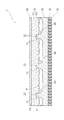
図1は、第1実施形態における再帰反射シートの断面を示す図である。図2は、第1実施形態における再帰反射層の断面を示す図である。図1及び図2に示すように、本実施形態における再帰反射シート1は、再帰反射層10、結合材層20および表面保護層30を主な構成要素として備える。
(1) First Embodiment FIG. 1 is a view showing a cross section of a retroreflective sheet in the first embodiment. FIG. 2 is a diagram showing a cross section of the retroreflective layer in the first embodiment. As shown in FIGS. 1 and 2, the
再帰反射層10は、保持体部11と複数の再帰反射素子12とを一体化した単一の層である。この再帰反射層10は、保持体部11側から入射した光を再帰反射素子12と、結合材層20によって形成される空間との界面IFで内部全反射し、入射した光を再帰反射させる。
The
保持体部11は、再帰反射層10において板状の部位である。この保持体部11の一面F1には複数の再帰反射素子12が設けられている。複数の再帰反射素子12は、入射した光を再帰反射させるのに適した反射面を有している限り特に限定されるものではない。
The
特に、三角錐などの多面体の再帰反射素子を最密充填状に配置して再帰反射素子12が形成された場合、反射性能が優れるので好ましい。
In particular, when the
本実施形態における保持体部11の一面F1には、複数の再帰反射素子12が設けられていない領域ARがあり、当該領域ARには保持体部11の一面F1とは反対側の他面F2に向かって凹む凹部13が設けられている。
The one surface F1 of the
この凹部13は保持体部11を貫通しておらず、領域ARの幅W1と凹部13の幅W2とは同じとされる。すなわち、凹部13の開口縁は領域ARの境界と一致しており、当該凹部13に配置される結合部22とその結合部22の周縁にある再帰反射素子12とは接している。
The
なお、領域ARの幅W1は、凹部13の開口を通る直線と領域ARとの交点を結ぶ線分のうち最も大きい線分の長さである。また、凹部13の幅W2は、再帰反射層10の厚さ方向の断面においてその厚さ方向とは直交する方向の直線と凹部13との交点を結ぶ線分のうち最も大きい線分の長さである。
The width W1 of the region AR is the length of the largest line segment among the line segments that connect the intersections of the straight line passing through the opening of the
本実施形態の場合、領域ARは、複数の領域ARを有しており、当該領域ARそれぞれに断面略矩形状の凹部13が設けられている。
In the case of the present embodiment, the area AR has a plurality of areas AR, and each of the areas AR is provided with a
このような再帰反射層10の材料としては、光学的特性に優れたものがよい。例えば、ポリカーボネート系樹脂、塩化ビニル系樹脂、フッ化ビニリデン系樹脂、アクリル系樹脂、エポキシ系樹脂、スチレン系樹脂、ポリエステル系樹脂、フッ素系樹脂、ポリエチレン系樹脂、オレフィン系樹脂、セルロース系樹脂、ウレタン系樹脂などが挙げられる。特に、フッ化ビニリデン系樹脂、アクリル系樹脂が好ましい。
As a material for such a
フッ化ビニリデン系樹脂としては、例えば、ポリフッ化ビニリデン、フッ化ビニリデン−テトラフルオロエチレン共重合体、フッ化ビニリデン−ヘキサフルオロプロピレン共重合体、フッ化ビニリデン−テトラフルオロエチレン−ヘキサフルオロプロピレン共重合体、フッ化ビニリデン−テトラフルオロエチレン−プロピレン共重合体、フッ化ビニリデン−テトラフルオロエチレン−パーフルオロ(メチルビニルエーテル)共重合体などが挙げられる。 As the vinylidene fluoride resin, for example, polyvinylidene fluoride, vinylidene fluoride-tetrafluoroethylene copolymer, vinylidene fluoride-hexafluoropropylene copolymer, vinylidene fluoride-tetrafluoroethylene-hexafluoropropylene copolymer , Vinylidene fluoride-tetrafluoroethylene-propylene copolymer, vinylidene fluoride-tetrafluoroethylene-perfluoro(methyl vinyl ether) copolymer and the like.
アクリル系樹脂としては、例えば、ポリメタクリル酸メチル樹脂、ポリメタクリル酸エチル樹脂、ポリメタクリル酸プロピル、ポリメタクリル酸ブチル、ポリアクリル酸メチル、アクリル酸エチル、ポリアクリル酸プロピル、ポリアクリル酸ブチル、ポリアクリル酸2エチルヘキシルなどが挙げられる。 Examples of the acrylic resin include polymethyl methacrylate resin, polyethyl methacrylate resin, polypropyl methacrylate, polybutyl methacrylate, polymethyl acrylate, ethyl acrylate, polypropyl acrylate, polybutyl acrylate, and polybutyl acrylate. 2-ethylhexyl acrylate and the like can be mentioned.
なお、耐候性及び柔軟性を向上させる観点では、フッ化ビニリデン系樹脂とアクリル系樹脂とを含有する樹脂組成物で形成される再帰反射層10であることが好ましい。耐候性に優れるフッ化ビニリデン系樹脂と柔軟性に優れるアクリル系樹脂とを含む樹脂組成物により層を形成することで、再帰反射層の耐候性及び柔軟性に優れたものにすることができる。
From the viewpoint of improving weather resistance and flexibility, the
結合材層20は、再帰反射層10の再帰反射素子側の面に対向して配置される層であって、再帰反射層10と結合する結合部22を部分的に有する単一の層である。この結合材層20は、結合部22を介して再帰反射層10(複数の再帰反射素子12)と結合材層20自身との間に空間を形成する。
The
結合部22は、保持体部11の凹部13内に配置され、凹部13の側面または底面と結合することで、再帰反射層10と結合材層20とを結合する。なお、図1の例では、結合部22は、凹部13の側面及び底面の双方と結合することで、当該凹部13内に埋め込まれている。
The
本実施形態における結合部22は、保持体部11に設けられる各凹部13の数と同じ数だけ有し、1つの凹部13に対し1つの結合部22が割り当てられている。ただし、結合部22は、保持体部11に設けられる各凹部13の数よりも少ない数であっても良い。なお、結合部22の数が凹部13の数よりも少ない場合、当該結合部22が配置されていない凹部13が存在することになる。
The number of the
このような結合材層20の弾性率は、再帰反射層10の弾性率よりも低くされる。結合材層20の材料としては、例えば、再帰反射層10と同様の樹脂などが挙げられる。
The elastic modulus of such a
再帰反射層10との密着性をより高める場合、結合材層20は、再帰反射層10に含まれる同様の樹脂を含む樹脂組成物より形成されることが好ましい。さらに、着色剤、改質剤などの添加剤が含まれていてもよい。
In order to further improve the adhesiveness with the
表面保護層30は、再帰反射層10における保持体部11の一面F1とは反対側の他面F2を保護する光透過性の層であり、当該他面F2を覆うように設けられている。この表面保護層30の材料としては、例えば、再帰反射層10と同様のものが挙げられる。なお、表面保護層30は、再帰反射シート1の外部から光が入射する側の層とされる。
The surface
粘着剤層40は、結合材層20において結合部22が存在する側の一面とは反対側の他面に設けられる。この粘着剤層40の材料としては、例えば、アクリル系樹脂、エポキシ系樹脂、フェノール系樹脂、酢酸ビニル系樹脂、ニトリルゴム系樹脂、シリコーンゴム系樹脂などが挙げられる。
The pressure-
なお、再帰反射シート1が未使用のときには、粘着剤層40において結合材層20に対向する一面とは反対側の他面に剥離層50が積層され、当該粘着剤層40にゴミなどが付着することが防止される。一方、再帰反射シート1を使用するときには、剥離層50は粘着剤層40から剥離される。
When the
以上のとおり、本実施形態の再帰反射シート1では、保持体部11に凹部13が設けられている分だけ、結合部22が配置される部位の保持体部11の厚さが薄くなり、当該凹部13には保持体部11の弾性率よりも低い結合部が配置されている。
As described above, in the
このため、再帰反射シート1は結合部22付近で屈曲し易くなる。したがって、この再帰反射シート1では、当該再帰反射シート1の屈曲部位を基準として隣接する再帰反射素子12同士が衝突したり、再帰反射素子12が変形や損傷したりする場合などの事態が低減される。こうして、反射性能を低減することなく、曲面追従性を向上し得る再帰反射シートを提供することができる。
Therefore, the
(2)第2実施形態
図3は、第2実施形態における再帰反射シートの断面を示す図である。図4は、第2実施形態における再帰反射層の断面を示す図である。図3及び図4に示すように、本実施形態における再帰反射シートでは、第1実施形態の凹部13とは異なる凹部63を有している点で、第1実施形態の再帰反射シート1と相違する。
(2) Second Embodiment FIG. 3 is a view showing a cross section of the retroreflective sheeting in the second embodiment. FIG. 4 is a diagram showing a cross section of the retroreflective layer in the second embodiment. As shown in FIGS. 3 and 4, the retroreflective sheet according to the present embodiment differs from the
すなわち、第1実施形態における凹部13の底は保持体部11の他面F2に至っておらず、当該凹部13は保持体部11を貫通していなかった。
That is, the bottom of the
これに対して、本実施形態における凹部63の底は保持体部11の他面F2に達しており、当該凹部63は保持体部11を貫通している。この凹部63に配置される結合部22は、保持体部11の他面F2にまで延在し、表面保護層30と結合している。また、凹部63内における結合部22の側面は隙間なく凹部の内壁と接している。
On the other hand, the bottom of the
このような本実施形態の再帰反射シートでは、保持体部11を貫通していない凹部13に結合部22が配置されている第1実施形態の場合に比べて、当該再帰反射シートが結合部22付近でより屈曲し易くなる。したがって、この再帰反射シートでは、当該再帰反射シートの屈曲部位を基準として隣接する再帰反射素子同士が衝突することがより低減され、この結果、再帰反射シートの曲面追従性がより向上する。
In such a retroreflective sheet of the present embodiment, the retroreflective sheet has a joining
(3)第3実施形態
図5は、第3実施形態における再帰反射シートの断面を示す図である。図5に示すように、本実施形態における再帰反射シートは、スリット14を新たに有している点で、第1実施形態の再帰反射シート1と相違する。
(3) Third Embodiment FIG. 5 is a diagram showing a cross section of a retroreflective sheet in a third embodiment. As shown in FIG. 5, the retroreflective sheet according to the present embodiment is different from the
スリット14は、再帰反射シートのうち凹部内に配置された結合部22が配置される部位に、保持体部11の他面F2から一面F1方向に向かって、設けられている。言い換えると、このスリット14は、保持体部11の一面F1において凹部13の底と対向する部位に設けられており、当該凹部13とは離間している。また、スリット14は、再帰反射層10と表面保護層30とに囲まれ、当該スリット14内には空間が形成される。本実施形態の場合、スリット14の断面が略三角形状とされ、凹部13の底に近づくにしたがってスリット14の先端が徐々に細くなっている。
The
このような本実施形態の再帰反射シートでは、スリット14が設けられていない場合に比べて、当該再帰反射シートが結合部22付近でより屈曲し易くなる。したがって、この再帰反射シートでは、当該再帰反射シートの屈曲部位を基準として隣接する再帰反射素子12同士が衝突することがより低減され、この結果、再帰反射シートの反射性能を低減することなく、曲面追従性がより向上する。
In such a retroreflective sheet according to the present embodiment, the retroreflective sheet is more likely to bend near the
(4)第4実施形態
図6は、第4実施形態における再帰反射シートの断面を示す図である。図6に示すように、本実施形態における再帰反射シートは、スリット24を新たに有している点で、第2実施形態の再帰反射シートと相違する。
(4) Fourth Embodiment FIG. 6 is a diagram showing a cross section of a retroreflective sheet in a fourth embodiment. As shown in FIG. 6, the retroreflective sheet according to the present embodiment is different from the retroreflective sheet according to the second embodiment in that the
このスリット24は、結合部22に設けられており、保持体部11の一面F1にまで至っていない。また、スリット24は、再帰反射層10と表面保護層30とに囲まれ、当該スリット24内には空間が形成される。本実施形態の場合、スリット24の断面が略三角形状とされ、保持体部11の一面F1に近づくにしたがってスリット24の先端が徐々に細くなっている。
The
このような本実施形態の再帰反射シートでは、上記第3実施形態の場合と同様に、スリット24が設けられていない場合に比べて再帰反射シートの曲面追従性がより向上する。
In the retroreflective sheeting of this embodiment, as in the case of the third embodiment, the curved surface followability of the retroreflective sheeting is further improved as compared with the case where the
(5)第5実施形態
図7は、第5実施形態における再帰反射シートの断面を示す図である。図8は、第5実施形態における再帰反射層の断面を示す図である。図7及び図8に示すように、本実施形態における再帰反射シートでは、第1実施形態の領域ARとは異なる大きさの領域ARとなっている点で、第1実施形態の再帰反射シート1と相違する。
(5) Fifth Embodiment FIG. 7 is a diagram showing a cross section of a retroreflective sheet in a fifth embodiment. FIG. 8 is a diagram showing a cross section of the retroreflective layer in the fifth embodiment. As shown in FIGS. 7 and 8, in the retroreflective sheeting of the present embodiment, the area AR has a size different from that of the area AR of the first embodiment. Is different from.
すなわち、第1実施形態における領域ARの幅W1は、凹部13の幅W2と同じとされた。すなわち、凹部13の開口縁は領域ARの境界と一致しており、当該凹部13に配置される結合部22とその結合部22の周縁にある再帰反射素子12とは接していた。
That is, the width W1 of the region AR in the first embodiment is the same as the width W2 of the
これに対して、本実施形態における領域ARの幅W10は、凹部13の幅W2よりも大きい。すなわち、凹部13の開口縁は領域ARの境界の内側にあり、当該凹部13に配置される結合部22とその結合部22の周縁にある再帰反射素子12とには隙間GPが設けられ、当該結合部22と再帰反射素子12とは離間している。言い換えると、凹部13の開口縁は領域ARの境界の内側にあり、当該開口縁と境界との間に複数の再帰反射素子12はない。
On the other hand, the width W10 of the area AR in the present embodiment is larger than the width W2 of the
このような本実施形態の再帰反射シートでは、結合部22とその結合部22の周縁にある再帰反射素子12とが接している第1実施形態の場合に比べて、当該再帰反射素子12と結合部22とが衝突することが低減される。この結果、再帰反射シートの曲面追従性がより向上する。
In such a retroreflective sheet of the present embodiment, as compared with the case of the first embodiment in which the
なお、上記第2実施形態〜上記第4実施形態における保持体部11の領域ARが、本実施形態における保持体部11の領域ARとされても良い。
The area AR of the holding
(6)変形例
以上、第1実施形態〜第5実施形態が一例として挙げられた。しかしながら本発明は上記実施形態に限定されるものではない。
(6) Modifications The first to fifth embodiments have been described above as examples. However, the present invention is not limited to the above embodiment.
例えば、上記実施形態では、保持体部11の他面F2側に表面保護層30が設けられた。しかしながら、表面保護層30は省略されても良い。
For example, in the above-described embodiment, the surface
また、上記実施形態では、再帰反射層10における保持体部11と再帰反射素子12とが一体化された。しかしながら、再帰反射層10における保持体部11と再帰反射素子12とは一体化されていなくても良い。
Further, in the above-described embodiment, the holding
また、上記実施形態では、結合材層20は単一の層とされた。しかしながら、結合材層は必要に応じて結合材層と組成が同一もしくは相異なる複数の層で構成されていても良い。
Further, in the above embodiment, the
また、上記第3実施形態では、保持体部11の一面F1において凹部13の底と対向する部位にスリット14が設けられた。しかしながら、スリット14に代えて、もしくは、当該スリット14に加えて、表面保護層30を正面視した場合に、当該表面保護層30において結合部22と重なる部位にスリットが設けられていても良い。
Further, in the third embodiment described above, the
また、上記第4実施形態では、結合部22にスリット24が設けられた。しかしながら、スリット24に代えて、もしくは、当該スリット24に加えて、表面保護層30を正面視した場合に、当該表面保護層30において結合部22と重なる部位にスリットが設けられていても良い。
Further, in the fourth embodiment described above, the
また、上記実施形態では、凹部13又は63における断面の形状が略矩形状とされた。しかしながら、凹部13又は63における断面の形状は種々の形状を適用可能である。例えば、保持体部11の一面F1から他面F2に近づくほど凹部の側面が広がる形状、あるいは、当該保持体部11の一面F1から他面F2に近づくほど凹部の側面が狭まる形状などが適用可能である。なお、凹部13又は63の形状に応じて、当該凹部13又は63に隙間なく配置される結合部22の形状も適宜変更される。
Further, in the above-described embodiment, the cross-sectional shape of the
1・・・再帰反射シート
10・・・再帰反射層
11・・・保持体部
12・・・再帰反射素子
13,63・・・凹部
14,24・・・スリット
20・・・結合材層
22・・・結合部
30・・・表面保護層
40・・・粘着剤層
50・・・剥離層
AR・・・領域
DESCRIPTION OF
Claims (3)
前記再帰反射層の再帰反射素子側の面に対向して配置される層であって、前記再帰反射層と結合する結合部を部分的に有する結合材層と、
を備える再帰反射シートであって、
前記結合材層の弾性率は、前記保持体部の弾性率よりも低く、
前記保持体部の一面には前記複数の再帰反射素子が設けられていない領域が設けられるとともに、前記領域には前記保持体部の一面とは反対側の他面に向かって凹む凹部が設けられ、
前記結合部は、前記凹部内に配置され、
前記凹部内に配置される前記結合部と、その結合部の周縁にある前記再帰反射素子との間には隙間が設けられ、当該結合部とその結合部の周縁にある前記再帰反射素子とが前記隙間を介して離間し、
前記再帰反射シートの前記結合部が配置されている部位の少なくとも一部に、前記保持体部の前記他面から前記一面の方向に向かって、前記凹部の底と対向して前記底とは離間するスリットが設けられる
ことを特徴とする再帰反射シート。 A retroreflective layer having a plate-shaped holding member and a plurality of retroreflective elements provided on one surface of the holding member,
A layer arranged to face the surface of the retroreflective layer on the side of the retroreflective element, and a binder layer partially having a coupling part that is coupled to the retroreflective layer,
A retroreflective sheeting Ru provided with,
The elastic modulus of the binder layer is lower than the elastic modulus of the holding body portion,
An area where the plurality of retroreflective elements are not provided is provided on one surface of the holding body portion, and a recessed portion that is recessed toward the other surface opposite to the one surface of the holding body portion is provided in the area. ,
The coupling portion is disposed in the recess,
A gap is provided between the coupling portion arranged in the recess and the retroreflective element on the periphery of the coupling portion, and the coupling portion and the retroreflective element on the periphery of the coupling portion are Separated via the gap ,
At least a part of the portion of the retroreflective sheet where the coupling portion is arranged, faces the bottom of the recess and separates from the bottom from the other surface of the holding body in the direction of the one surface. A retroreflective sheeting characterized in that a slit is provided .
前記再帰反射層の再帰反射素子側の面に対向して配置される層であって、前記再帰反射層と結合する結合部を部分的に有する結合材層と、
を備える再帰反射シートであって、
前記結合材層の弾性率は、前記保持体部の弾性率よりも低く、
前記保持体部の一面には前記複数の再帰反射素子が設けられていない領域が設けられるとともに、前記領域には前記保持体部の一面とは反対側の他面に向かって凹み、前記保持体部を貫通しない凹部が設けられ、
前記結合部は、前記凹部内に配置され、
前記再帰反射シートの前記結合部が配置されている部位の少なくとも一部に、前記保持体部の前記他面から前記一面の方向に向かって、前記凹部の底と対向して前記底とは離間するスリットが設けられる
ことを特徴とする再帰反射シート。 A retroreflective layer having a plate-shaped holding member and a plurality of retroreflective elements provided on one surface of the holding member,
A layer arranged to face the surface of the retroreflective layer on the side of the retroreflective element, and a binder layer partially having a coupling part that is coupled to the retroreflective layer,
A retroreflective sheeting Ru provided with,
The elastic modulus of the binder layer is lower than the elastic modulus of the holding body portion,
An area where the plurality of retroreflective elements are not provided is provided on one surface of the holding body portion, and the area is recessed toward the other surface on the opposite side to the one surface of the holding body portion. A recess that does not penetrate the section is provided,
The coupling portion is disposed in the recess ,
At least a part of the portion of the retroreflective sheet where the coupling portion is arranged, faces the bottom of the recess and separates from the bottom from the other surface of the holding body in the direction of the one surface. A retroreflective sheeting characterized in that a slit is provided .
前記再帰反射層の再帰反射素子側の面に対向して配置される層であって、前記再帰反射層と結合する結合部を部分的に有する結合材層と、
を備え、
前記結合材層の弾性率は、前記保持体部の弾性率よりも低く、
前記保持体部の一面には前記複数の再帰反射素子が設けられていない領域が設けられるとともに、前記領域には前記保持体部の一面から当該一面とは反対側の他面にわたって貫通する凹部が設けられ、
前記結合部は、前記凹部内に配置されるとともに前記一面から前記他面まで延在し、
前記結合部の少なくとも一部に、前記保持体部の前記他面から前記一面の方向に向かって、前記一面にまで至らないスリットが設けられる
ことを特徴とする再帰反射シート。
A retroreflective layer having a plate-shaped holding member and a plurality of retroreflective elements provided on one surface of the holding member,
A layer arranged to face the surface of the retroreflective layer on the side of the retroreflective element, and a binder layer partially having a coupling part that is coupled to the retroreflective layer,
Equipped with
The elastic modulus of the binder layer is lower than the elastic modulus of the holding body portion,
A region in which the plurality of retroreflective elements are not provided is provided on one surface of the holding body portion, and a concave portion that penetrates from one surface of the holding body portion to the other surface opposite to the one surface is provided in the region. Is provided,
The coupling portion is disposed in the recess and extends from the one surface to the other surface,
A retroreflective sheet, characterized in that at least a part of the coupling portion is provided with a slit that does not reach the one surface from the other surface of the holding body portion toward the one surface.
Priority Applications (1)
| Application Number | Priority Date | Filing Date | Title |
|---|---|---|---|
| JP2015147941A JP6748985B2 (en) | 2015-07-27 | 2015-07-27 | Retroreflective sheeting |
Applications Claiming Priority (1)
| Application Number | Priority Date | Filing Date | Title |
|---|---|---|---|
| JP2015147941A JP6748985B2 (en) | 2015-07-27 | 2015-07-27 | Retroreflective sheeting |
Publications (2)
| Publication Number | Publication Date |
|---|---|
| JP2017026950A JP2017026950A (en) | 2017-02-02 |
| JP6748985B2 true JP6748985B2 (en) | 2020-09-02 |
Family
ID=57945864
Family Applications (1)
| Application Number | Title | Priority Date | Filing Date |
|---|---|---|---|
| JP2015147941A Active JP6748985B2 (en) | 2015-07-27 | 2015-07-27 | Retroreflective sheeting |
Country Status (1)
| Country | Link |
|---|---|
| JP (1) | JP6748985B2 (en) |
Family Cites Families (8)
| Publication number | Priority date | Publication date | Assignee | Title |
|---|---|---|---|---|
| US5614286A (en) * | 1993-10-20 | 1997-03-25 | Minnesota Mining And Manufacturing Company | Conformable cube corner retroreflective sheeting |
| US5905099A (en) * | 1995-11-06 | 1999-05-18 | Minnesota Mining And Manufacturing Company | Heat-activatable adhesive composition |
| US5784197A (en) * | 1996-04-01 | 1998-07-21 | Minnesota Mining And Manufacturing Company | Ultra-flexible retroreflective sheeting with coated back surface |
| CN1283456C (en) * | 1999-09-10 | 2006-11-08 | 3M创新有限公司 | Retroreflective articles having multilayer films and methods of mfg. same |
| US6925965B1 (en) * | 2004-07-28 | 2005-08-09 | Nite Glow Industries, Inc. | Omnidirectional reflective pet leash |
| EP2558289B1 (en) * | 2010-04-15 | 2018-12-26 | 3M Innovative Properties Company | Retroreflective articles including optically active areas and optically inactive areas |
| WO2012166448A1 (en) * | 2011-05-31 | 2012-12-06 | 3M Innovative Properties Company | Retroreflective articles having composite cube-corners and methods of making |
| US20160011346A1 (en) * | 2014-07-14 | 2016-01-14 | Sergiy Vasylyev | High incidence angle retroreflective sheeting |
-
2015
- 2015-07-27 JP JP2015147941A patent/JP6748985B2/en active Active
Also Published As
| Publication number | Publication date |
|---|---|
| JP2017026950A (en) | 2017-02-02 |
Similar Documents
| Publication | Publication Date | Title |
|---|---|---|
| CN108962028B (en) | Flexible display screen cover plate, flexible display module and flexible display device | |
| KR102404974B1 (en) | Display device | |
| WO2022188420A1 (en) | Display module and display device | |
| JP6704235B2 (en) | Dispenser and shield | |
| JP5971551B2 (en) | Retainer for sensor mounting | |
| EP1974646A3 (en) | Cleaning element and cleaning tool | |
| EP3228675A1 (en) | A screen protector for a mobile electronic device with a touch screen | |
| JP3200045U (en) | Protective film composite | |
| JP6748985B2 (en) | Retroreflective sheeting | |
| JP6176423B2 (en) | Anti-scattering film, 3D curved glass with anti-scattering film | |
| JP6673619B2 (en) | Retroreflective sheet | |
| CN106090729A (en) | Backlight module and include its display device | |
| JP5224980B2 (en) | Blister package | |
| JP2007057934A (en) | Reflector and its manufacturing method | |
| JP2010124593A (en) | Electric-wire protective material | |
| JP2021061351A5 (en) | ||
| JP2017083480A (en) | Retroreflective sheet | |
| KR102074173B1 (en) | Dashboard cover fixing pad | |
| JP6629558B2 (en) | Cable fixing structure | |
| JP2006183710A (en) | Protectional member | |
| JP6669563B2 (en) | Corner guard | |
| JP2008297747A (en) | Fixture member for corner, and its packing method | |
| KR20200000399A (en) | Dashboard cover fixing pad | |
| JP2022077090A (en) | Label-attached good | |
| WO2013069539A1 (en) | Fresnel mirror, fresnel mirror attachment structure, and method for detaching fresnel mirror |
Legal Events
| Date | Code | Title | Description |
|---|---|---|---|
| A621 | Written request for application examination |
Free format text: JAPANESE INTERMEDIATE CODE: A621 Effective date: 20180614 |
|
| A977 | Report on retrieval |
Free format text: JAPANESE INTERMEDIATE CODE: A971007 Effective date: 20190426 |
|
| A131 | Notification of reasons for refusal |
Free format text: JAPANESE INTERMEDIATE CODE: A131 Effective date: 20190528 |
|
| A521 | Request for written amendment filed |
Free format text: JAPANESE INTERMEDIATE CODE: A523 Effective date: 20190719 |
|
| A131 | Notification of reasons for refusal |
Free format text: JAPANESE INTERMEDIATE CODE: A131 Effective date: 20191224 |
|
| A521 | Request for written amendment filed |
Free format text: JAPANESE INTERMEDIATE CODE: A523 Effective date: 20200219 |
|
| TRDD | Decision of grant or rejection written | ||
| A01 | Written decision to grant a patent or to grant a registration (utility model) |
Free format text: JAPANESE INTERMEDIATE CODE: A01 Effective date: 20200721 |
|
| RD04 | Notification of resignation of power of attorney |
Free format text: JAPANESE INTERMEDIATE CODE: A7424 Effective date: 20200730 |
|
| A61 | First payment of annual fees (during grant procedure) |
Free format text: JAPANESE INTERMEDIATE CODE: A61 Effective date: 20200729 |
|
| R150 | Certificate of patent or registration of utility model |
Ref document number: 6748985 Country of ref document: JP Free format text: JAPANESE INTERMEDIATE CODE: R150 |
|
| R250 | Receipt of annual fees |
Free format text: JAPANESE INTERMEDIATE CODE: R250 |