JP6748641B2 - Welding of steel blanks - Google Patents
Welding of steel blanks Download PDFInfo
- Publication number
- JP6748641B2 JP6748641B2 JP2017520513A JP2017520513A JP6748641B2 JP 6748641 B2 JP6748641 B2 JP 6748641B2 JP 2017520513 A JP2017520513 A JP 2017520513A JP 2017520513 A JP2017520513 A JP 2017520513A JP 6748641 B2 JP6748641 B2 JP 6748641B2
- Authority
- JP
- Japan
- Prior art keywords
- blank
- support
- blanks
- steel
- laser
- Prior art date
- Legal status (The legal status is an assumption and is not a legal conclusion. Google has not performed a legal analysis and makes no representation as to the accuracy of the status listed.)
- Active
Links
- 229910000831 Steel Inorganic materials 0.000 title claims description 57
- 239000010959 steel Substances 0.000 title claims description 57
- 238000003466 welding Methods 0.000 title claims description 42
- 238000000034 method Methods 0.000 claims description 65
- 229910052782 aluminium Inorganic materials 0.000 claims description 42
- XAGFODPZIPBFFR-UHFFFAOYSA-N aluminium Chemical compound [Al] XAGFODPZIPBFFR-UHFFFAOYSA-N 0.000 claims description 42
- 238000004804 winding Methods 0.000 claims description 36
- 230000004907 flux Effects 0.000 claims description 17
- 239000000463 material Substances 0.000 claims description 15
- 239000002245 particle Substances 0.000 claims description 15
- 229910000838 Al alloy Inorganic materials 0.000 claims description 13
- 239000000696 magnetic material Substances 0.000 claims description 11
- CSDREXVUYHZDNP-UHFFFAOYSA-N alumanylidynesilicon Chemical compound [Al].[Si] CSDREXVUYHZDNP-UHFFFAOYSA-N 0.000 claims description 9
- 238000010791 quenching Methods 0.000 claims description 9
- 238000010438 heat treatment Methods 0.000 claims description 8
- 230000000171 quenching effect Effects 0.000 claims description 8
- 229910000521 B alloy Inorganic materials 0.000 claims description 5
- 238000005304 joining Methods 0.000 claims description 5
- 230000003287 optical effect Effects 0.000 claims description 5
- 239000000843 powder Substances 0.000 description 19
- XEEYBQQBJWHFJM-UHFFFAOYSA-N Iron Chemical group [Fe] XEEYBQQBJWHFJM-UHFFFAOYSA-N 0.000 description 11
- 229910052751 metal Inorganic materials 0.000 description 11
- 239000002184 metal Substances 0.000 description 11
- 239000006249 magnetic particle Substances 0.000 description 8
- 238000000576 coating method Methods 0.000 description 7
- 230000008569 process Effects 0.000 description 7
- 229910000797 Ultra-high-strength steel Inorganic materials 0.000 description 6
- 239000011248 coating agent Substances 0.000 description 6
- 238000004519 manufacturing process Methods 0.000 description 6
- PXHVJJICTQNCMI-UHFFFAOYSA-N Nickel Chemical compound [Ni] PXHVJJICTQNCMI-UHFFFAOYSA-N 0.000 description 5
- 238000009434 installation Methods 0.000 description 5
- 229910052742 iron Inorganic materials 0.000 description 5
- 239000007791 liquid phase Substances 0.000 description 5
- 239000000203 mixture Substances 0.000 description 5
- 239000000047 product Substances 0.000 description 5
- 229910001566 austenite Inorganic materials 0.000 description 4
- 239000011651 chromium Substances 0.000 description 4
- 230000007797 corrosion Effects 0.000 description 4
- 238000005260 corrosion Methods 0.000 description 4
- 229910052804 chromium Inorganic materials 0.000 description 3
- 239000007789 gas Substances 0.000 description 3
- 229910000734 martensite Inorganic materials 0.000 description 3
- 238000002844 melting Methods 0.000 description 3
- 230000008018 melting Effects 0.000 description 3
- 229910052750 molybdenum Inorganic materials 0.000 description 3
- 239000012071 phase Substances 0.000 description 3
- 230000001681 protective effect Effects 0.000 description 3
- 229910052710 silicon Inorganic materials 0.000 description 3
- 229910000859 α-Fe Inorganic materials 0.000 description 3
- IJGRMHOSHXDMSA-UHFFFAOYSA-N Atomic nitrogen Chemical compound N#N IJGRMHOSHXDMSA-UHFFFAOYSA-N 0.000 description 2
- OKTJSMMVPCPJKN-UHFFFAOYSA-N Carbon Chemical compound [C] OKTJSMMVPCPJKN-UHFFFAOYSA-N 0.000 description 2
- VYZAMTAEIAYCRO-UHFFFAOYSA-N Chromium Chemical compound [Cr] VYZAMTAEIAYCRO-UHFFFAOYSA-N 0.000 description 2
- ZOKXTWBITQBERF-UHFFFAOYSA-N Molybdenum Chemical compound [Mo] ZOKXTWBITQBERF-UHFFFAOYSA-N 0.000 description 2
- XUIMIQQOPSSXEZ-UHFFFAOYSA-N Silicon Chemical compound [Si] XUIMIQQOPSSXEZ-UHFFFAOYSA-N 0.000 description 2
- 230000015572 biosynthetic process Effects 0.000 description 2
- 229910052799 carbon Inorganic materials 0.000 description 2
- 239000012467 final product Substances 0.000 description 2
- 239000001307 helium Substances 0.000 description 2
- 229910052734 helium Inorganic materials 0.000 description 2
- SWQJXJOGLNCZEY-UHFFFAOYSA-N helium atom Chemical compound [He] SWQJXJOGLNCZEY-UHFFFAOYSA-N 0.000 description 2
- 239000012535 impurity Substances 0.000 description 2
- 239000011572 manganese Substances 0.000 description 2
- 230000004048 modification Effects 0.000 description 2
- 238000012986 modification Methods 0.000 description 2
- 239000011733 molybdenum Substances 0.000 description 2
- 229910052759 nickel Inorganic materials 0.000 description 2
- 230000002787 reinforcement Effects 0.000 description 2
- 239000010703 silicon Substances 0.000 description 2
- 238000012360 testing method Methods 0.000 description 2
- 229910052719 titanium Inorganic materials 0.000 description 2
- 239000010936 titanium Substances 0.000 description 2
- 229910000712 Boron steel Inorganic materials 0.000 description 1
- 229910001209 Low-carbon steel Inorganic materials 0.000 description 1
- PWHULOQIROXLJO-UHFFFAOYSA-N Manganese Chemical compound [Mn] PWHULOQIROXLJO-UHFFFAOYSA-N 0.000 description 1
- RTAQQCXQSZGOHL-UHFFFAOYSA-N Titanium Chemical compound [Ti] RTAQQCXQSZGOHL-UHFFFAOYSA-N 0.000 description 1
- 238000010521 absorption reaction Methods 0.000 description 1
- 230000003213 activating effect Effects 0.000 description 1
- 229910045601 alloy Inorganic materials 0.000 description 1
- 239000000956 alloy Substances 0.000 description 1
- JZQOJFLIJNRDHK-CMDGGOBGSA-N alpha-irone Chemical compound CC1CC=C(C)C(\C=C\C(C)=O)C1(C)C JZQOJFLIJNRDHK-CMDGGOBGSA-N 0.000 description 1
- PNEYBMLMFCGWSK-UHFFFAOYSA-N aluminium oxide Inorganic materials [O-2].[O-2].[O-2].[Al+3].[Al+3] PNEYBMLMFCGWSK-UHFFFAOYSA-N 0.000 description 1
- 229910001563 bainite Inorganic materials 0.000 description 1
- 230000008901 benefit Effects 0.000 description 1
- 230000008859 change Effects 0.000 description 1
- 229910052729 chemical element Inorganic materials 0.000 description 1
- 239000010941 cobalt Substances 0.000 description 1
- 229910017052 cobalt Inorganic materials 0.000 description 1
- GUTLYIVDDKVIGB-UHFFFAOYSA-N cobalt atom Chemical compound [Co] GUTLYIVDDKVIGB-UHFFFAOYSA-N 0.000 description 1
- 239000002131 composite material Substances 0.000 description 1
- 239000000470 constituent Substances 0.000 description 1
- 238000010276 construction Methods 0.000 description 1
- 238000005261 decarburization Methods 0.000 description 1
- 230000007547 defect Effects 0.000 description 1
- 238000011161 development Methods 0.000 description 1
- 230000000694 effects Effects 0.000 description 1
- 230000005672 electromagnetic field Effects 0.000 description 1
- 238000005516 engineering process Methods 0.000 description 1
- 238000002474 experimental method Methods 0.000 description 1
- 239000000945 filler Substances 0.000 description 1
- 239000010419 fine particle Substances 0.000 description 1
- 239000002223 garnet Substances 0.000 description 1
- 230000005484 gravity Effects 0.000 description 1
- 230000001678 irradiating effect Effects 0.000 description 1
- 238000000608 laser ablation Methods 0.000 description 1
- 238000003754 machining Methods 0.000 description 1
- 229910052748 manganese Inorganic materials 0.000 description 1
- WPBNNNQJVZRUHP-UHFFFAOYSA-L manganese(2+);methyl n-[[2-(methoxycarbonylcarbamothioylamino)phenyl]carbamothioyl]carbamate;n-[2-(sulfidocarbothioylamino)ethyl]carbamodithioate Chemical compound [Mn+2].[S-]C(=S)NCCNC([S-])=S.COC(=O)NC(=S)NC1=CC=CC=C1NC(=S)NC(=O)OC WPBNNNQJVZRUHP-UHFFFAOYSA-L 0.000 description 1
- 239000011159 matrix material Substances 0.000 description 1
- 239000000155 melt Substances 0.000 description 1
- 229910001092 metal group alloy Inorganic materials 0.000 description 1
- 238000002156 mixing Methods 0.000 description 1
- 229910052757 nitrogen Inorganic materials 0.000 description 1
- 230000003647 oxidation Effects 0.000 description 1
- 238000007254 oxidation reaction Methods 0.000 description 1
- 230000004792 oxidative damage Effects 0.000 description 1
- 229910001562 pearlite Inorganic materials 0.000 description 1
- 230000035515 penetration Effects 0.000 description 1
- 230000008707 rearrangement Effects 0.000 description 1
- 230000008521 reorganization Effects 0.000 description 1
- 238000011272 standard treatment Methods 0.000 description 1
- 239000000126 substance Substances 0.000 description 1
- 239000000758 substrate Substances 0.000 description 1
- 238000004381 surface treatment Methods 0.000 description 1
- 238000012546 transfer Methods 0.000 description 1
- 239000013585 weight reducing agent Substances 0.000 description 1
- 238000005493 welding type Methods 0.000 description 1
- 229910052727 yttrium Inorganic materials 0.000 description 1
- VWQVUPCCIRVNHF-UHFFFAOYSA-N yttrium atom Chemical compound [Y] VWQVUPCCIRVNHF-UHFFFAOYSA-N 0.000 description 1
Images


Classifications
-
- B—PERFORMING OPERATIONS; TRANSPORTING
- B23—MACHINE TOOLS; METAL-WORKING NOT OTHERWISE PROVIDED FOR
- B23K—SOLDERING OR UNSOLDERING; WELDING; CLADDING OR PLATING BY SOLDERING OR WELDING; CUTTING BY APPLYING HEAT LOCALLY, e.g. FLAME CUTTING; WORKING BY LASER BEAM
- B23K26/00—Working by laser beam, e.g. welding, cutting or boring
- B23K26/20—Bonding
- B23K26/21—Bonding by welding
- B23K26/24—Seam welding
- B23K26/26—Seam welding of rectilinear seams
-
- B—PERFORMING OPERATIONS; TRANSPORTING
- B23—MACHINE TOOLS; METAL-WORKING NOT OTHERWISE PROVIDED FOR
- B23K—SOLDERING OR UNSOLDERING; WELDING; CLADDING OR PLATING BY SOLDERING OR WELDING; CUTTING BY APPLYING HEAT LOCALLY, e.g. FLAME CUTTING; WORKING BY LASER BEAM
- B23K37/00—Auxiliary devices or processes, not specially adapted to a procedure covered by only one of the preceding main groups
- B23K37/04—Auxiliary devices or processes, not specially adapted to a procedure covered by only one of the preceding main groups for holding or positioning work
- B23K37/0408—Auxiliary devices or processes, not specially adapted to a procedure covered by only one of the preceding main groups for holding or positioning work for planar work
-
- B—PERFORMING OPERATIONS; TRANSPORTING
- B23—MACHINE TOOLS; METAL-WORKING NOT OTHERWISE PROVIDED FOR
- B23K—SOLDERING OR UNSOLDERING; WELDING; CLADDING OR PLATING BY SOLDERING OR WELDING; CUTTING BY APPLYING HEAT LOCALLY, e.g. FLAME CUTTING; WORKING BY LASER BEAM
- B23K26/00—Working by laser beam, e.g. welding, cutting or boring
- B23K26/20—Bonding
- B23K26/32—Bonding taking account of the properties of the material involved
- B23K26/322—Bonding taking account of the properties of the material involved involving coated metal parts
-
- B—PERFORMING OPERATIONS; TRANSPORTING
- B23—MACHINE TOOLS; METAL-WORKING NOT OTHERWISE PROVIDED FOR
- B23K—SOLDERING OR UNSOLDERING; WELDING; CLADDING OR PLATING BY SOLDERING OR WELDING; CUTTING BY APPLYING HEAT LOCALLY, e.g. FLAME CUTTING; WORKING BY LASER BEAM
- B23K2101/00—Articles made by soldering, welding or cutting
- B23K2101/006—Vehicles
-
- B—PERFORMING OPERATIONS; TRANSPORTING
- B23—MACHINE TOOLS; METAL-WORKING NOT OTHERWISE PROVIDED FOR
- B23K—SOLDERING OR UNSOLDERING; WELDING; CLADDING OR PLATING BY SOLDERING OR WELDING; CUTTING BY APPLYING HEAT LOCALLY, e.g. FLAME CUTTING; WORKING BY LASER BEAM
- B23K2101/00—Articles made by soldering, welding or cutting
- B23K2101/18—Sheet panels
- B23K2101/185—Tailored blanks
-
- B—PERFORMING OPERATIONS; TRANSPORTING
- B23—MACHINE TOOLS; METAL-WORKING NOT OTHERWISE PROVIDED FOR
- B23K—SOLDERING OR UNSOLDERING; WELDING; CLADDING OR PLATING BY SOLDERING OR WELDING; CUTTING BY APPLYING HEAT LOCALLY, e.g. FLAME CUTTING; WORKING BY LASER BEAM
- B23K2101/00—Articles made by soldering, welding or cutting
- B23K2101/34—Coated articles, e.g. plated or painted; Surface treated articles
-
- B—PERFORMING OPERATIONS; TRANSPORTING
- B23—MACHINE TOOLS; METAL-WORKING NOT OTHERWISE PROVIDED FOR
- B23K—SOLDERING OR UNSOLDERING; WELDING; CLADDING OR PLATING BY SOLDERING OR WELDING; CUTTING BY APPLYING HEAT LOCALLY, e.g. FLAME CUTTING; WORKING BY LASER BEAM
- B23K2103/00—Materials to be soldered, welded or cut
- B23K2103/08—Non-ferrous metals or alloys
Description
本出願は、2014年10月15日に出願された欧州特許出願14382394.6の利益を主張する。 This application claims the benefit of European patent application 13822394.6 filed on October 15, 2014.
本開示は、2つの鋼のブランクを接合する方法に関し、より特別な鋼のブランクは、少なくともアルミニウムまたはアルミニウム合金の層を備える。本開示は、さらにこれらの方法を実施するための道具、及びこれらの方法のいずれかによって得られるまたは得ることが可能な生産物に関する。 The present disclosure relates to a method of joining two steel blanks, the more specific steel blank comprising at least a layer of aluminum or an aluminum alloy. The disclosure further relates to tools for practicing these methods, and the products obtained or obtainable by any of these methods.
例えば、自動車工業における重量を減らす要求は、軽い材料、製造過程、道具の開発や実施につながってきた。乗員の安全に関する関心の高まりは、衝突の間、エネルギの吸収を改良する一方で、自動車の完全性を改良する材料の採用につながってきた。そのような意味で、高強度及び超高強度の鋼(ultra−high−strength steel(UHSS))で作られた自動車の部品は、しばしば軽量の構造物のための基準を満足するために用いられる。 For example, the demand for weight reduction in the automotive industry has led to the development and implementation of lighter materials, manufacturing processes and tools. Increasing occupant safety concerns have led to the adoption of materials that improve the absorption of energy during a crash while improving the integrity of the vehicle. In that sense, automotive parts made of high-strength and ultra-high-strength steel (UHSS) are often used to meet the criteria for lightweight construction. ..
超高強度の鋼(UHSS)は、単位重さあたりの最適化された最高の強度と、有利な成形性の特性を示す。これらの鋼は、良好な機械的特性を与え、特に自動車の部品における鋼のブランクを形成するために使われる典型的なホットスタンピング工程を特にそれらに適合させる、熱処理後の微細構造を成し遂げるために考案される。いくつかのホットスタンピング工程において、ボロンの鋼のシートが、1500MPa以下の引張強度で、UHSS特性をもつスタンプされた部品を作るために使われる。他の材料と比較して強度が増加すると、使われるゲージ材料をより薄くし、コールドスタンプされた軟鋼の部品よりも重さを節約する結果をもたらす。 Ultra High Strength Steel (UHSS) exhibits optimized maximum strength per unit weight and advantageous formability characteristics. These steels have good mechanical properties, in particular to achieve a microstructure after heat treatment, which makes them particularly compatible with the typical hot stamping processes used to form steel blanks in automotive parts. Devised. In some hot stamping processes, sheets of boron steel are used to make stamped parts with UHSS properties at tensile strengths below 1500 MPa. The increased strength compared to other materials results in thinner gauge materials used and weight savings over cold stamped mild steel parts.
ホットスタンピングに使われるUHSSから作られることが可能な、典型的な自動車部品は、ドアのはり、バンパのはり、断面/側面部材、フロント/センタ ピラー補強材、及びウエストレール補強材を含む。 Typical automotive components that can be made from UHSS used for hot stamping include door beams, bumper beams, cross section/side members, front/center pillar reinforcements, and waist rail reinforcements.
構造上の必須条件に関する一方、部品の重さを最小にすることのさらなる試みにおいて、いわゆる「仕立てられたブランク」(tailored blank)技術が使われてもよい。これらの技術において、部品は、厚さ、大きさ、特性の異なるいくつかのブランクの「端部から端部」を溶接することによって得られる複合金属ブランクから作られるかもしれない。少なくとも理論的に、この種の技術を使うことにより、材料は最適に使用されるかもしれない。厚さが異なるブランクが、接続されるかもしれず、または鋼のブランクは、例えばそれらが必要とされるそれぞれの材料の特別な性質を使っている、被覆された鋼のブランクと接続されるかもしれない。 While relating to structural requirements, so-called "tailored blank" techniques may be used in a further attempt to minimize component weight. In these techniques, parts may be made from composite metal blanks obtained by welding the "end to end" of several blanks of different thickness, size and properties. At least theoretically, the material may be optimally used by using this type of technique. Blanks of different thicknesses may be joined, or steel blanks may be joined with coated steel blanks, for example using the special properties of the respective material in which they are needed. Absent.
同様に、いくつかのブランクが「端部から端部へ」溶接される必要はなく、代わりにブランクの部分または完全な重なりが使われていてもよい「寄せ集め」(patchwork)ブランクが知られている。 Similarly, some blanks do not have to be welded "end to end" and instead a portion or full overlap of the blanks may be used, known as "patchwork" blanks. ing.
ホットスタンピング工程の間、ブランクは、積極的に大気にさらされるため、鋼は、通常、腐食、酸化、脱炭及びスケール形成を避けるためにコーティングが施される。22MnB5鋼は、通常、アルミニウム−シリコン被膜がされている。例えば、Usibor(登録商標)1500Pは、商業的にArcelor社から入手可能であるが、アルミニウムシリコン(AlSi)被膜で被覆されたボロン合金鋼であり、仕立てられた、寄せ集めブランクで通常使われる鋼の例である。 During the hot stamping process, the blank is actively exposed to the atmosphere, so the steel is usually coated to avoid corrosion, oxidation, decarburization and scale formation. 22MnB5 steel is usually aluminum-silicon coated. For example, Usibor® 1500P, commercially available from Arcelor, is a boron alloy steel coated with an aluminum silicon (AlSi) coating, a steel commonly used in tailored, jumble blanks. Is an example of.
Usibor(登録商標)1500Pは、フェライト−パーライト相で供給される。同種のパターンが繰り返される微粒子構造である。機械的特性は、この構造に関連する。ホットスタンピング工程、およびその後に続く焼き入れの加熱後、マルテンサイト微細構造が作り出される。結果として、最大強度及び引張強度は著しく増加する。 Usibor® 1500P is supplied in the ferrite-pearlite phase. It is a fine particle structure in which the same kind of pattern is repeated. Mechanical properties are associated with this structure. After the hot stamping step and subsequent heating of the quench, martensitic microstructures are created. As a result, maximum strength and tensile strength are significantly increased.
Usiborの組成物は、下記のように重量パーセントでまとめられる(残りは鉄(Fe)及び不純物)

前述のように、Usibor1500は腐食及び酸化の損傷を避けるためにアルミニウム−シリコン(AlSi)被膜がある。しかしながら、この被膜は、その溶接行動に関連して重要な不都合な点を有する。もし、Usiborブランクがいかなるさらなる方策もなく溶接されるならば、被膜のアルミニウムは、溶接領域に入り込み、これにより、結果となる部品の機械的特性を重度に減少させ、溶接領域における弱い裂け目の可能性を増加させることになる。 As previously mentioned, the Usibor 1500 has an aluminum-silicon (AlSi) coating to avoid corrosion and oxidative damage. However, this coating has important disadvantages in connection with its welding behaviour. If the Usibor blank is welded without any further measures, the aluminum of the coating penetrates into the weld zone, which severely reduces the mechanical properties of the resulting part and allows for weak cracks in the weld zone. Sex will be increased.
この効果を避けるまたは少なくとも最小化するために、レーザアブレーションによって溶接の裂け目に近い領域の被膜を部分的に(または完全に)除去することが知られている。しかしながら、これにより、(仕立てられた)ブランクおよび自動車部品の製造工程において追加の段階が生じる。さらに、この追加の段階により、廃棄されるべき部分の数が高められた複雑な品質の工程が必要となる。これにより溶接段階のコストが増加し、工業的に技術の競争が限定される。 To avoid or at least minimize this effect, it is known to partially (or completely) remove the coating in the region near the weld crevice by laser ablation. However, this results in an additional step in the manufacturing process of (tailored) blanks and motor vehicle parts. Moreover, this additional step requires a complex quality process with an increased number of parts to be discarded. This increases the cost of the welding stage and limits technical competition in the industry.
ここで、ブランクは、1以上の工程段階(変形、機械加工、表面処理、またはその他)を、まだ、経なければならない品物として見なされるかもしれない。これらの品物は、実質的に平らなプレートまたはさらに複雑な形状を有するかもしれない。 Here, a blank may be considered as an article that has still to undergo one or more process steps (deformation, machining, surface treatment, or otherwise). These items may have substantially flat plates or more complex shapes.
独国特許102007028956号(特許文献1)は、溶接の裂け目でおおよそ水平な溶接のための方法及び器具を記載している。 DE 102007028956 describes a method and an apparatus for welding which is approximately horizontal at the crevice of the welding.
欧州特許2737971号(特許文献2)は、厚さと材料の異なるブランクを接続することによって作製された、仕立てられ溶接されたブランク、その作製方法および、それらを用いたホットスタンピングした部品、を記載している。 EP 2 737 971 describes tailor-welded blanks made by connecting blanks of different thickness and material, a method of making them and hot stamped parts using them. ing.
それゆえ、前述の不利な点を避けるまたは少なくとも部分的に減らす、アルミニウムまたはアルミニウム合金の層を少なくとも有する鋼のブランクを接続する方法が必要である。 Therefore, there is a need for a method of connecting steel blanks having at least a layer of aluminum or an aluminum alloy that avoids or at least partially reduces the aforementioned disadvantages.
第1の態様において、開示により、第1の鋼のブランク及び第2の鋼のブランクを接続し、第1及び第2のブランクうち少なくとも1つは、アルミニウムまたはアルミニウム合金の層を備える方法が提供される。それぞれの鋼のブランクのための、支持物を提供することを備え、支持物は、磁性材料で作られ、それらの間に提供された中心空間によって隔てられ離れて配置される方法である。コイル巻線は、少なくとも支持物の1つの周りに提供される。使用している間、第1及び第2のブランクの中を通って支持体の間で磁束の経路を閉じる接触領域を画定し、第2のブランクに面する第1のブランクの端部は、第1のブランクに面する第2のブランクの端部に接せられるように1つの支持体に第1のブランクと他の支持体に第2のブランクを配置し、レーザシステムを提供することを備え、レーザシステムは、1以上の光学素子とレーザビームを発生するレーザ源を備える方法である。さらにレーザシステムを用いて、接触領域にレーザビームを照射し、一方で、交流磁場が実質的に一方のブランクから他方のブランクの方向へ接触領域に渡って発生するように、コイル巻線に交流電流を流すことを備える方法である。 In a first aspect, the disclosure provides a method of connecting a first steel blank and a second steel blank, wherein at least one of the first and second blanks comprises a layer of aluminum or an aluminum alloy. To be done. Providing a support for each steel blank, the support being a method made of magnetic material and spaced apart by a central space provided between them. Coil windings are provided around at least one of the supports. During use, the end of the first blank facing the second blank that defines a contact area that closes the path of the magnetic flux between the supports through the first and second blanks, Placing the first blank on one support and the second blank on the other support so as to contact the end of the second blank facing the first blank to provide a laser system. A laser system comprising a one or more optical elements and a laser source for generating a laser beam. Further, a laser system is used to irradiate the contact area with a laser beam, while alternating current is applied to the coil windings so that an alternating magnetic field is generated substantially across the contact area from one blank towards the other. A method comprising passing an electric current.
この態様によれば、磁性材料によって作られている支持体(そして、空間を空けて離れて配置された)に配置され、接触している鋼のブランクを持ってくることによって、磁束のためのポテンシャルの経路は、ブランクに渡って支持体の間で閉じられる。コイル巻線に交流電流を流すことによって、交流磁場は、鋼のブランクを横切る支持体に起きる。磁場の強さは、磁性支持体の周りにコイルを巻くことで増加する。磁場は、ブランクの幅に渡って、与えまたは与えられるかもしれない。 According to this embodiment, by bringing a steel blank placed in contact with (and spaced apart from) a support made of magnetic material, The potential path is closed between the supports across the blank. By passing an alternating current through the coil windings, an alternating magnetic field is created in the support across the steel blank. The strength of the magnetic field is increased by winding a coil around the magnetic support. The magnetic field may or may be applied across the width of the blank.
交流磁場が、レーザビームと同時に与えられたとき、ブランクの部分(接触領域)が液相になり、磁場は、ブランクを横切る(レーザとともに動くのではなく、ブランクの幅に渡って)。ブランクが実質的に平らであるときに、磁場は、それゆえ、実質的にブランクと一体となった一直線と考えられる。 When an alternating magnetic field is applied at the same time as the laser beam, a portion of the blank (contact area) goes into liquid phase and the magnetic field crosses the blank (rather than moving with the laser, across the width of the blank). When the blank is substantially flat, the magnetic field is therefore considered to be substantially a straight line with the blank.
一般に、レーザは、実質的にブランクに垂直に狙われるかもしれない。交流磁場は、それゆえ一般的に実質的にレーザに垂直であるかもしれない。 In general, the laser may be aimed substantially perpendicular to the blank. The alternating magnetic field may therefore generally be substantially perpendicular to the laser.
磁性材料の液相において、交流磁場があると、非磁性材料がいかなる変化も気付かない一方で、液相に存在する磁性粒子の再編成に影響を与える。交流磁場の強さにより、磁性粒子を引き込むようになる。つまり、他の言葉に置き換えれば、磁性粒子は、継続的な横の再配列にあることができる。反対に、非磁性粒子は実質的に交流磁場を意に介せず、それゆえ、まだとどまり、そして重力によって落ちる。実質的に非磁性粒子であるアルミニウム粒子は溶接の機械的特性をそれゆえ高める接触領域からそれゆえ取り除かれ、または少なくとも部分的に取り除かれることにつながる。 An alternating magnetic field in the liquid phase of a magnetic material affects the reorganization of the magnetic particles present in the liquid phase, while the non-magnetic material is unaware of any changes. Due to the strength of the alternating magnetic field, magnetic particles are attracted. That is, in other words, magnetic particles can be in continuous lateral rearrangement. On the contrary, non-magnetic particles are essentially impervious to the alternating magnetic field and therefore remain and fall by gravity. The aluminum particles, which are substantially non-magnetic particles, thus lead to the removal, or at least partial removal, from the contact area, which thus enhances the mechanical properties of the weld.
例えば被覆された鋼のブランクが溶接された時、いくつかの既存の技術の方法で提案されているように、アルミニウムまたはアルミニウム合金を取り除く必要がある。これにより、中間の工程段階がさらに必要とされないため、製造工程が速く安くなる。 For example, when a coated steel blank is welded, it is necessary to remove the aluminum or aluminum alloy, as suggested by some existing art methods. This makes the manufacturing process faster and cheaper because no additional intermediate process steps are required.
アルミニウム合金は、ここでアルミニウムが主たる元素である金属合金として理解されることである。 Aluminum alloy is to be understood here as a metal alloy in which aluminum is the main element.
いくつかの実施例において、第1のブランク及び/または第2のブランクは、例えばUsiborブランクのように、アルミニウムシリコンでコーティングされたボロン合金鋼から作られてもよい。 In some embodiments, the first blank and/or the second blank may be made of aluminum silicon coated boron alloy steel, such as a Usibor blank.
ここで以前に記載された方法は、2つのブランクを接続する端部により、例えば仕立てられたブランクを形成するために使われてもよい。ブランクの一方または両方のブランクは、アルミニウムまたはアルミニウム合金の層を備える被膜を有する鋼の基材を備えていてもよい。特に、AlSi被膜は、使われるかもしれない。他の例は、Ductibor(登録商標)ブランクの使用を含む。 The method previously described here may be used, for example, to form a tailored blank with the ends connecting the two blanks. One or both blanks may comprise a steel substrate with a coating comprising a layer of aluminum or aluminum alloy. In particular, AlSi coatings may be used. Other examples include the use of Ductibor® blanks.
第2の態様として、本開示は、第1の鋼のブランクと第2の鋼のブランクを接続し、少なくとも第1または第2のブランクの1つは、アルミニウムまたはアルミニウムの合金の層を備える道具を提供する。道具は、第1のブランクを備える第1の支持体と第2のブランクを備える第2の支持体を備え、第1及び第2の支持体は、磁性材料で作られ、それらの間に提供された中心空間によって隔てられ離れて配置されている。道具はさらに、第1及び第2の支持体のいずれかの周りに提供される第1のコイル巻線を備える。第2のコイル巻線は、さらに第1及び第2の支持体の他方の周りに提供されてもよい。第1及び第2のコイル巻線は、交流電流がそれらに与えられたとき、発生された磁場が反転するように配置されていてもよい。 In a second aspect, the present disclosure connects a first steel blank and a second steel blank, at least one of the first or second blanks comprising a layer of aluminum or an alloy of aluminum. I will provide a. The tool comprises a first support with a first blank and a second support with a second blank, the first and second supports being made of a magnetic material and provided between them. They are separated from each other by the central space and are arranged apart. The tool further comprises a first coil winding provided around either of the first and second supports. A second coil winding may also be provided around the other of the first and second supports. The first and second coil windings may be arranged such that the magnetic field generated is reversed when an alternating current is applied to them.
第3の態様において、本開示は、製品を形成する方法を提供する。ここで記載された方法のいずれかによって第1及び第2の鋼のブランクを接続する方法を含むブランクを形成し、そして続けて、ブランクを加熱し、そして加熱されたブランクを熱で変形し、そして最後に焼き入れをすることを備える方法である。加熱は、変形の前に加熱炉で熱処理することを含むかもしれない。加熱変形は、例えば、ホットスタンピングまたは深絞りを含んでいてもよい。 In a third aspect, the present disclosure provides a method of forming a product. Forming a blank comprising a method of connecting a first and a second steel blank by any of the methods described herein, and subsequently heating the blank and thermally deforming the heated blank, Finally, it is a method that includes quenching. Heating may include heat treating in a furnace prior to deformation. The heat deformation may include, for example, hot stamping or deep drawing.
そしてさらなる態様において、第1の鋼のブランクと第2の鋼のブランクを接続し、ここで、第1及び第2のブランクの少なくとも1つは、アルミニウムまたはアルミニウム合金の層を備える別の方法が提供される。交流磁場源を提供し、第1のブランクの端部が第2のブランクの端部に面するように、溶接線が、溶接されるべき第1のブランクと第2のブランクの端部に沿って画定されるように、第1のブランクと第2のブランクを提供することを備える方法である。さらにレーザシステムを提供し、レーザシステムは、1以上の光学素子とレーザビームを発生するためのレーザ光源を備え、レーザシステムを使ってレーザビームを溶接線に沿って照射し、実質的に続けて、実質的に一方のブランクから他方のブランクの方向へ、溶接線に渡って磁束を生成する交流磁場源を稼働させ、ここで、磁場は磁性元素が落ちない一方で、アルミニウム元素が落ちるようになることを備える方法である。 And in a further aspect, another method connects a first steel blank and a second steel blank, wherein at least one of the first and second blanks comprises a layer of aluminum or an aluminum alloy. Provided. A welding line is provided along the edges of the first and second blanks to be welded so as to provide an alternating magnetic field source and the edges of the first blank face the edges of the second blank. A method comprising providing a first blank and a second blank as defined by. Further provided is a laser system, the laser system comprising one or more optical elements and a laser light source for producing a laser beam, wherein the laser system is used to illuminate the laser beam along a weld line, substantially continuously. , Operating an alternating magnetic field source that produces a magnetic flux across the weld line, substantially in the direction of one blank to the other, where the magnetic field is such that the magnetic element does not fall while the aluminum element falls. Is a method of providing
さらなる態様において、本開示は、実質的にここで以前に記載された方法のいずれかによって得られるまたは得ることができるブランク及び製品を提供する。 In a further aspect, the present disclosure provides blanks and products substantially obtained or obtainable by any of the methods previously described herein.
本開示の限定されない例は、添付された図を参照することで次に記載される。 Non-limiting examples of the present disclosure are described next with reference to the accompanying figures.
図1は、概略的に第1の鋼のブランク10及び第2の鋼のブランク11を接続するための方法を実施する道具の部分を描く。この例において、2つのブランクは、例えば端部から端部へ溶接することを使用して、端部が接続されることになる。さらにこの例では、両方のブランクは、例えばUsibor(登録商標)1500Pのようなボロン合金の被覆された鋼から作られ、厚さが異なっていてもよい。変形例では、他の鋼のブランクが使われてもよい。さらに変形例では、両方のブランクは同じ厚さを有していてもよい。
FIG. 1 schematically depicts the part of a tool implementing the method for connecting a
道具は、第1のブランク10を支持する第1のテーブル20及び第2のブランク11を支持する第2のテーブルを備える。第1及び第2のテーブルは、鋼または他の磁性のまたは磁化可能な材料で作られていてもよい。テーブル20及び21はそれらの間に提供される中心空間30によって隔てられ離れて配置されていてもよい。描かれた例では、2つのブランクは、実質的に同じ平面で配置される。さらに描かれていない例では、ブランクは、それらの間に角度を持って配置されることができる。
The tool comprises a first table 20 supporting a first blank 10 and a second table supporting a second blank 11. The first and second tables may be made of steel or other magnetic or magnetizable material. The tables 20 and 21 may be separated and spaced apart by a
2つのブランクを接続するここで以前に記載された方法を実行すると、ブランクが磁性材料で作られたテーブルに配置され、ブランクが、お互いに接せられたとき、磁束の可能な経路は、ブランクの中を通ってテーブルの間で閉じられる。さらに磁束の可能な経路は、テーブルとテーブル20、21の下側(ブランクが支持されるのとは反対側)に接触する場所に置かれる道具の下側基部33の間でも閉じられるかもしれない。この場合において、下側基部33は磁性のまたは磁化可能な材料で作られることができる。
Performing the method previously described here for connecting two blanks, when the blanks are placed on a table made of magnetic material and the blanks are abutted against each other, the possible paths of the magnetic flux are Passed through and closed between the tables. Furthermore, the possible path of the magnetic flux may also be closed between the table and the
第1のコイル巻線40は、第1のテーブル20の周りに提供されてもよく、そして、第2のコイル巻線41は、第2のテーブル21の周りに提供されてもよい。この例においては、交流電流が両方のコイル巻線40、41に流れたときに、発生される磁場が逆になるように気をつけるべきである。N極とS極はそれゆえ、2つのコイルで反対方向に発生する。それゆえ、磁束の経路は、ブランクを通ってN極からS極へ、支持体の下側を通ってN極からS極へ効率的になる。
The first coil winding 40 may be provided around the first table 20 and the second coil winding 41 may be provided around the second table 21. In this example, care should be taken that the magnetic fields generated are reversed when an alternating current flows through both
図2aから4bはアルミニウム層を備えるブランクを接続する道具のさらなる例を示す。これらの図に示される例において、同じ符号は対応する要素を指し示すために使われる。これらの例において、ブランクは、端部が接続されるようになり、ブランクは、図1の例のように厚さが異なる。さらに描かれない例において、ブランクは、同じ厚さを有するかもしれず、及び/またはそれらの間で角度を持って配置されていてもよい。 2a to 4b show further examples of tools for connecting blanks with aluminum layers. In the examples shown in these figures, the same reference numerals are used to indicate corresponding elements. In these examples, the blanks become end-to-end connected and the blanks differ in thickness as in the example of FIG. In examples not depicted further, the blanks may have the same thickness and/or may be angularly arranged between them.
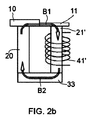
図2a−2bの例は、単一のコイル巻線41’が例えば、第2のテーブル21’の周りに提供されているかもしれない点で、図1のそれとは異なる。さらなる例において、単一のコイルは、交流電流が、交流磁場を発生するためのコイル巻線に与えられることである限りは、第1または第2のテーブル20’、21’のいずれかの周りに提供されることができた。これらの例においては、下側基部33は、図1の例との連結で説明されるようなテーブル20、21’の下側(ブランクが支持されているのとは反対側)に接触するように提供されていてもよい。下側基部33は、磁性のまたは磁化可能な材料で作られることができる。これらの場合において、交流電流が単一コイル41’に与えられたとき、N極とS極は、コイル41’の反対側に発生するであろう。磁束の経路はそれゆえ矢印A1、A2、B1、及びB2で示され、周期的にその方向を反転し、磁場を生成する電気の変化の流れに従う。磁束の経路は、それゆえブランク10、11(矢印A1及びB1)の中を通って、及び下側基部33(矢印A2及びB2)の中を通ってテーブル20、21’の間で閉じられている。
The example of Figures 2a-2b differs from that of Figure 1 in that a single coil winding 41' may be provided, for example, around the second table 21'. In a further example, a single coil may be provided around either the first or second table 20', 21', so long as an alternating current is applied to the coil windings for generating an alternating magnetic field. Could be offered to. In these examples, the
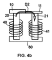
図3a−3bの例は、下側基部がテーブル20、21の間で提供されない点で図1とは異なる。これらの例において、図1の例と同様に、交流電流がコイル巻線40、41へ与えられたときに発生された磁場が反対になるように注意すべきである。この方法では、N極とS極は2つのコイル巻線40、41の反対側へ発生するであろう。磁束の経路は、矢印C1及びC2で表され、それゆえ、周期的にその方向を反転し、磁場を発生するコイルを通して円運動をする電気の変化の流れに従うだろう。磁束の経路は、それゆえブランク10、11の中を通るのみ(矢印C1及びC2)のテーブル20、21の間で形成されることができる。
The example of Figures 3a-3b differs from Figure 1 in that the lower base is not provided between the tables 20,21. In these examples, as in the example of FIG. 1, care should be taken that the magnetic fields generated when an alternating current is applied to the
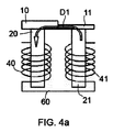
図4a及び4bの例はコイル巻線40、41が、例えば、連結ケーブル60によってお互いに連結されてもよい点で、図3a、3bのそれとは異なる。コイル40、41は、それゆえ、交流電流が印加されたときに、N極とS極がコイル巻線40、41のそれぞれの自由終端に発生するように直列に連結される。これらの例によると、自由終端401、411は、ブランク10、11に面して提供されてもよく、そして、連結ケーブル60は、それぞれのコイルの他の端部に接続してもよい。磁束経路は、矢印D1及びD2で表され、周期的にその方向を反転し、磁場を発生するようにコイルを通って円運動をする電気の変化の流れにもよることができる。磁束の経路は、それゆえブランク10、11の中を通るのみ(矢印D1及びD2)のテーブル20、21の間で形成されることができる。
The example of Figures 4a and 4b differs from that of Figures 3a, 3b in that the
さらに、変形例では、第1の支持体(例えば「テーブル20」)、第2の支持体(例えば「テーブル21」)及び下側基部は一体的に形成されてもよい。 Further, in a modification, the first support (for example, "table 20"), the second support (for example, "table 21") and the lower base may be integrally formed.
すべての場合において、道具は、さらにレーザビーム(概略的に矢印50で示される)が射出されるレーザヘッドを有するレーザ溶接装置を備えていてもよい。この例では、レーザシステムは、レーザビーム50が実質的にブランクの伸びている方向に垂直な方向にブランク10、11に照射されるように配置されることができる。変形例において、レーザビームは、斜めの方向でブランクに照射されてもよい。
In all cases, the tool may further comprise a laser welding device having a laser head from which a laser beam (schematically indicated by arrow 50) is emitted. In this example, the laser system may be arranged such that the
任意に、コレクター板31は、交流磁場が与えられた時に前述したように実質的に重力によって落ちるかもしれないアルミニウム粒子を集めるために中心空間30に提供されてもよい。いくつかのこれらの場合において、コレクター板は鋼で作ることができる。いくつかの場合において、下側基部33の上に配置されてもよい。
Optionally, a
いくつかの実施例において、道具は、さらにそれぞれのテーブル20、21、21’のそれぞれの上側(ブランクが支持されるためにある)に関連し、使用中にそれぞれのクランプがブランク10、11を支持されているテーブル20、21、21’に押しつけるように配置されたクランプ(図示せず)を備えていてもよい。 In some embodiments, the tool is further associated with the respective upper side of each table 20, 21, 21' (for the blank to be supported) such that each clamp holds the blank 10, 11 in use. It may include a clamp (not shown) arranged to press against the supported table 20, 21, 21'.
ブランクを接続するために、レーザビームは、ブランクの端部を加熱し、端部を溶かす。交流電流は、コイルに渡って、交流磁場を作るように両方のコイルに印加される。コイルと電流は、1つのコイルに作られた磁場が他のコイルに作られた磁場と反対方向であるようにされる。 To connect the blanks, the laser beam heats the ends of the blanks and melts the ends. An alternating current is applied to both coils across the coils to create an alternating magnetic field. The coils and currents are such that the magnetic field created in one coil is in the opposite direction to the magnetic field created in the other coil.
第1のコイル(第1の支持体において)、第2のコイル(第2の支持体において)に渡る磁場、ブランク及び基部は、それゆえ磁束の方向が何度も変化する閉じた円を形成することができる。端部に溶かされた「磁性の」粒子は、何度も変化する磁場に気付き、続けてそれに従い再配置される。アルミニウム粒子は、しかしながら、磁場によって影響されず、すなわち、それらは、まだ残り、それゆえ溶接領域から落ちる。それらは、コレクター板31に収集することができる。
The magnetic field across the first coil (at the first support), the second coil (at the second support), the blank and the base thus form a closed circle in which the direction of the magnetic flux changes many times. can do. The "magnetic" particles melted at the edges notice a changing magnetic field many times and are subsequently rearranged accordingly. The aluminum particles, however, are unaffected by the magnetic field, ie they remain and therefore fall out of the weld area. They can be collected on the
いくつかの実施例において、交流電流の周波数は、例えば50Hzまたは60Hzである。これらは、50Hzまたは60Hzは、地形による、電気の送電網の通常の周波数であるので、非常に単純であることを意味する。 In some embodiments, the frequency of the alternating current is, for example, 50Hz or 60Hz. These mean that 50 Hz or 60 Hz is very simple, as it is the normal frequency of the electrical grid, depending on the terrain.
図5a及び5bは、アルミニウム層を備えるブランクを接続するための工作機械の据え付け及び方法のさらなる別の例を示す。これらの図で示される例において、同じ符号は、対応する要素を指し示すために使われている。 5a and 5b show yet another example of a machine tool installation and method for connecting a blank comprising an aluminum layer. In the examples shown in these figures, the same reference numerals are used to indicate corresponding elements.
この例においては、ブランクは、端部で接合されることであり、同じまたは異なる厚さを有してもよい。さらに変形例において、ブランクは、それらの間において角度をつけて配置されてもよかった。 In this example, the blanks are to be joined at the ends and may have the same or different thickness. In a further variation, the blanks could be arranged at an angle between them.
この例において、2つの磁石E1、E2は、ブランク10、11のそれぞれの底部に配置することができる。その代わりに、磁石、または複数の磁石は、ブランクのそれぞれの下に配置してもよい。これらの磁石は電磁石であってもよい。
In this example, two magnets E1, E2 can be placed at the bottom of each of the
示された例において、溶接することによって接続されるブランク10、11の端部は、溶接線を画定するそれぞれに当たる。他の例においては、ブランクの端部の間に裂け目があってもよい。そのような裂け目は、溶接線を画定するための適切な充填材料で満たされてもよい。
In the example shown, the ends of the
磁石は、溶接線の領域に磁場の磁力線が実質的に溶接線に垂直に配置されるように、配置される。電磁石の場合において、それらは、DCまたはAC源に接続されていてもよく、使用中に、(周期的にその方向に戻る流れの変化による)逆になる(矢印F1,F2)磁場を発生するために逆にされたそれらの極性に配置されてよく、それゆえ、すなわち、矢印F1からF2及びその逆のような、ブランク10、11を通る磁束の方向を絶えず変化することが生じる。
The magnets are arranged such that the magnetic field lines of the magnetic field are arranged substantially perpendicular to the welding line in the region of the welding line. In the case of electromagnets, they may be connected to a DC or AC source and, in use, generate a reversing magnetic field (arrows F1, F2) (due to changes in the flow returning periodically in that direction). May be arranged with their polarities reversed for that reason, that is to say that the direction of the magnetic flux through the
溶接領域において、渦電流がレーザの照射において、変化する磁場の結果として発生してもよい。交流磁場F1、F2の強さは、(例えば、同時にレーザ熱の照射によって作り出された)ブランク10、11の液相を横切るとき、磁気素子または磁性粒子のローレンツ力が、磁性粒子を上に押し上げることは重要であるという結果になることができる。実質的に非磁性であるアルミニウム粒子は、これらのローレンツ力によって影響されない。この様にすることによって、アルミニウム粒子は、それゆえ磁性粒子が一緒に溶接されている一方、落ちるかもしれない。これは、アルミニウム層を備える2つのブランクがアルミニウムを取り除く余分な段階を経ずに一緒に溶接されることができることを意味する。
In the welding area, eddy currents may be generated in the irradiation of the laser as a result of the changing magnetic field. The strength of the alternating magnetic fields F1, F2 is such that the Lorentz force of the magnetic element or magnetic particles pushes the magnetic particles up as they traverse the liquid phase of the
これをすることによって、磁場の強さは、磁気素子/粒子に影響を与えるよう十分に強く、アルミニウム粒子/素子に影響を与えないよう十分に弱く、注意深く選択されることになる。この磁場の強さは、電流を制御すること、交流磁場の周波数、及び例えば、溶接領域の距離やブランクの厚さによって制御されることができる。 By doing this, the strength of the magnetic field is carefully chosen to be strong enough to affect the magnetic elements/particles and weak enough not to affect the aluminum particles/elements. The strength of this magnetic field can be controlled by controlling the current, the frequency of the alternating magnetic field and, for example, the distance of the welding area and the thickness of the blank.
図2a−4bの例において、磁場の強さは、さらにそれぞれのコイルを巻く数によって決まる。 In the example of Figures 2a-4b, the magnetic field strength is further determined by the number of turns of each coil.
いくつかの実施例において、道具はさらに磁場(電磁石)からコイル巻線を保護するために、コイル巻線があるまたはないテーブルに面した少なくとも側面において、中心空間を部分的に閉じる保護プレート32を備えていてもよい。保護プレート32は、実質的にブランク10、11に面するCの開口、C形状を備えていてもよい。いくつかの場合において、保護プレートは鋼で作られてもよい。
In some embodiments, the tool further includes a
いくつかの実施例において、レーザシステムは、3kWから16kWの間、任意に4から10kWの間の出力を有するレーザを備えていてもよい。レーザの出力は、ブランクの接触する領域を溶かすに十分であるべきであった。好ましくは、接触領域は、アルミニウムが同様に、厚さ全体から取り除かれるようにブランクの厚さ全体に沿って溶かされる。 In some embodiments, the laser system may comprise a laser having a power output between 3 kW and 16 kW, optionally between 4 and 10 kW. The power of the laser should be sufficient to melt the contact area of the blank. Preferably, the contact areas are melted along the entire thickness of the blank so that aluminum is likewise removed from the entire thickness.
発明者らは、3kW−5kWが典型的なブランク(典型的な厚さの範囲は0.7−4mm)を溶かすのに重要であるかもしれないことを発見した。範囲の上限に向かって溶接の出力を増加すると、溶接速度が上がるかもしれない。 The inventors have discovered that 3 kW-5 kW may be important for melting a typical blank (typical thickness range 0.7-4 mm). Increasing the welding power towards the upper end of the range may increase the welding speed.
交流磁場が生じると、ブランクにおけるレーザによって発生される温度が上がる。このように温度が上がると、湿度が減少し、それゆえ溶接が改善するのに役立つかもしれない。 The alternating magnetic field raises the temperature generated by the laser in the blank. This increase in temperature may help reduce humidity and therefore improve welding.
任意に、Nd−YAG(ネオジウムドープのイットリウムアルミナガーネット)レーザが使われてもよい。これらのレーザは、商業的に入手可能であり、実績のある技術を構成要素とする。この種類のレーザは、ブランクの領域を溶かすために十分な出力を有し、レーザの焦点の幅、それゆえ溶接領域の幅を変えることができる。「スポット」の大きさを小さくすることにより、エネルギ密度が上昇し、一方、スポットの大きさを大きくすると溶接工程の速度を上げることができる。溶接スポットは、非常に効率的に制御することができ、ツインスポット溶接及び波状のスポット溶接を含む様々な種類の溶接がこの種類のレーザで可能となるかもしれない。いくつかの実施例において、ヘリウムまたはヘリウム系ガスのような遮蔽ガスが用いられてもよい。遮蔽ガスの流量は、例えば1L/minから15L/minで変化させることができる。 Optionally, a Nd-YAG (neodymium-doped yttrium alumina garnet) laser may be used. These lasers are commercially available and consist of proven technology. This type of laser has sufficient power to melt the area of the blank and can change the width of the laser focus and hence the width of the weld area. Reducing the size of the "spot" increases the energy density, while increasing the size of the spot can speed up the welding process. The welding spots can be controlled very efficiently and various types of welding, including twin spot welding and wavy spot welding, may be possible with this type of laser. In some embodiments, a shielding gas such as helium or a helium-based gas may be used. The flow rate of the shielding gas can be changed, for example, from 1 L/min to 15 L/min.
変形例において、十分な出力のCO2レーザが使われてもよい。 In a variant, a full power CO 2 laser may be used.
いくつかの実施例において、溶接は、ツインスポット溶接を備えていてもよい。ツインスポット溶接において、溶融及び溶接は、2つの焦点で同時に起こる。2つのスポットは、溶接方向に対し、平行(平行なツインビームスポット)または垂直(垂直なツインビームスポット)に一直線に並べられてもよい。垂直なツインスポットは、広い溶融したプールをもたらし、少なくとも、理論的に、広い加熱領域のせいでキーホール溶接の代わりに対流溶接を生じさせることができた。平行なツインスポット(他の背後の1つ)は、溶接の間、より低い熱の勾配を伝達する。 In some examples, the weld may comprise a twin spot weld. In twin spot welding, melting and welding occur simultaneously at two foci. The two spots may be aligned parallel (parallel twin beam spot) or perpendicular (vertical twin beam spot) with respect to the welding direction. The vertical twin spots resulted in a large molten pool and, at least in theory, could have caused convection welding instead of keyhole welding due to the large heating area. The parallel twin spots (one behind the other) transfer a lower thermal gradient during welding.
平行なツインスポット溶接の態様は、材料がさらされる熱勾配が減らされているものである。垂直なツインスポット溶接の態様は、溶接領域が拡大されているものである。発明者らは、両方のこれらの配置を試み、両者は満足に働くことができることを見つけた。 The parallel twin-spot welding aspect is one in which the thermal gradient to which the material is exposed is reduced. A vertical twin-spot weld embodiment is one in which the weld area is enlarged. The inventors have tried both of these arrangements and have found that both can work satisfactorily.
いくつかの変形例において、溶接は、波状のスポット溶接を備えてもよい。波状のスポット溶接において、溶接スポットは、動的にレーザを反射する鏡の振動によって変化することができる。 In some variations, the weld may comprise a wavy spot weld. In wavy spot welding, the welding spot can be changed by the vibration of a mirror that dynamically reflects the laser.
ツインスポット溶接を用いる例において、レーザ出力は、2つの溶接スポットの間で等しくまたは等しくなく分けることができる。 In the example using twin spot welding, the laser power can be split equally or unequal between the two welding spots.
少なくとも1つのブランクがアルミニウムまたはアルミニウム合金の層を備える、2つの鋼のブランクを接続するここで以前に記載された道具を用いることによって、溶接の前にアルミニウム層を取り除く必要がなく、製造を単純にし、その速度を上げることができる。これにより、かなりのコストを下げることができる。 By using the tool previously described here to connect two steel blanks, at least one blank comprising a layer of aluminum or aluminum alloy, there is no need to remove the aluminum layer prior to welding, simplifying manufacturing And you can speed it up. This can reduce costs considerably.
Usiborブランクの標準な処理は、(特に)基礎鋼のオーステナイト化をもたらす例えば加熱炉において得られたブランクを加熱することになるであろう。それから、ブランクは、バンパはりやピラーを形成するためのホットスタンピングをするかもしれない。加熱変形後の焼き入れの間に、機械的な特性を満足しているマルテンサイト微細構造がそれゆえ得られるかもしれない。標準的な処理は、それゆえ、個々で提案された鋼のブランクを接続する方法によっていかなる影響も受けない。 The standard treatment of Usibor blanks would be to heat the blanks obtained, for example in a furnace, which leads to austenitization of the base steel (among others). The blank may then be hot stamped to form bumper beams or pillars. During quenching after heat deformation, martensitic microstructures satisfying mechanical properties may therefore be obtained. The standard process is therefore not affected by the individually proposed method of joining the steel blanks.
今までのところ、ここで描かれたすべての実施例において、平らなプレートの形状のブランクは、一緒に接続される。それゆえ、形成され仕立てられる溶接されたブランクは、以前に記載した同じ変形と加熱処理を受けてもよい。ここで開示された方法と道具の例は、異なる形状のブランクにも適用されてもよいことは明白であるべきである。 So far, in all the embodiments depicted here, the blanks in the form of flat plates are connected together. Therefore, the welded blank that is formed and tailored may undergo the same deformation and heat treatment as previously described. It should be clear that the example methods and tools disclosed herein may also be applied to blanks of different shapes.
さらなる例において、接触領域に金属粉を供給する間に溶接がされてもよい。金属粉は、それゆえ、液相でブランクと混合されてもよい。いくつかのこれらの実施形態において、金属粉は、ガンマ生成元素面(面心立方構造元素)を含む鉄ベースの粉を含んでいてもよい。この金属粉は、ブランクの表面の欠陥を隠すために使うことができる。いくつかの場合において、金属粉は、きれいな製造工程を確保するために管を通して与えることができる。 In a further example, the welding may be done while supplying the metal powder to the contact area. The metal powder may therefore be mixed with the blank in the liquid phase. In some of these embodiments, the metal powder may include an iron-based powder that includes gamma-generating element faces (face centered cubic structure elements). This metal powder can be used to hide defects on the surface of the blank. In some cases, the metal powder can be fed through a tube to ensure a clean manufacturing process.
金属粉がブランクを一緒に押しつける必要性を減らすために役立ってこともできる。裂け目がブランクの間にあるとき、いくつかの道具(例えば油圧)を一般にブランクを一緒に押しつけるために使うことができる。そのような道具は、しかしながら維持するためにコストがかかるかもしれない。ブランクの間の裂け目が大きすぎる(例えば0.15mmよりも大きい)場合、レーザ溶接は、使うことができなかった。 It can also serve to reduce the need for metal powder to press the blanks together. When the crevice is between the blanks, some tool (eg, hydraulic pressure) can generally be used to press the blanks together. Such tools, however, may be costly to maintain. If the crevice between the blanks was too large (eg greater than 0.15 mm), laser welding could not be used.
金属粉を提供することによって、変化する電磁場の結果、橋を、2つのブランクの間で形成することができる。金属粉の橋を、変化する磁場のために、落ちることなくブランクの間に維持することができる。これにより、それゆえ、ブランクを一緒に押しつける必要性が減り、以前不可能であったレーザ溶接を使うことができるかもしれない。 By providing a metal powder, a bridge can be formed between the two blanks as a result of the changing electromagnetic field. Due to the changing magnetic field, the bridge of metal powder can be maintained during the blank without falling. This would therefore reduce the need to press the blanks together and possibly use laser welding, which was not possible before.
そのような場合において、センサシステムを、ブランクの間の距離を測定するために配置してもよい。金属粉を、選択的に、ブランクの間の裂け目に応じて供給することができた。 In such cases, the sensor system may be arranged to measure the distance between the blanks. The metal powder could be selectively fed depending on the crevice between the blanks.
さらにこれらの例において、ガンマ生成元素を含む鉄ベースの粉を使うとき、溶接領域に導入し、あらゆるアルミニウムが残っている場合の溶かされたアルミニウムと混合してもよい。これにより、アルミニウムが少量残っている場合でさえ、ホットスタンピングのような熱変形工程の後に機械的特性が強化されるかもしれない。相対的にアルミニウムがほとんどないガンマ生成元素を含む鉄ベースの粉の混合物は、加熱の間、オーステナイト(ガンマ相鉄、γ−Fe)を得ることにつながる。そして、熱変形後の焼き入れの間、機械的強度を満足するマルテンサイト微細構造をそれゆえ得ることができる。 Further in these examples, when using iron-based powders containing gamma-generating elements, they may be introduced into the weld zone and mixed with the molten aluminum if any aluminum remains. This may enhance mechanical properties even after a small amount of aluminum remains, after a thermal deformation process such as hot stamping. A mixture of iron-based powders containing gamma-producing elements that are relatively aluminum-depleted leads to obtaining austenite (gamma-phase iron, γ-Fe) during heating. And, during quenching after thermal deformation, a martensite microstructure that satisfies the mechanical strength can thus be obtained.
ガンマ生成元素は、ここで、すなわちオーステナイト相のような、ガンマ相を促進する化学元素として理解されるべきである。ガンマ元素を、ニッケル(Ni)、炭素(C)、コバルト(Co)、マンガン(Mn)及び窒素(n)を含む群から選ぶことができる。他の要素は、例えば、硬度を上げる(モリブデン(Mo)が適当な元素かもしれない)及び/または耐腐食性(場合においては、シリコン(Si)及びクロム(Cr)が適当な化学成分かもしれない)のような金属粉の組成物を考慮に入れてもよい。 The gamma-generating element is to be understood here as a chemical element that promotes the gamma phase, ie, the austenite phase. The gamma element can be selected from the group including nickel (Ni), carbon (C), cobalt (Co), manganese (Mn) and nitrogen (n). Other factors may, for example, increase hardness (molybdenum (Mo) may be a suitable element) and/or corrosion resistance (in some cases silicon (Si) and chromium (Cr) may be suitable chemical constituents). Compositions of metal powders such as (without) may be taken into account.
粉体におけるガンマ生成元素の量は、Cr、Mo、Si、Al及びTi(チタン)のようなアルファ生成元素の存在を埋め合わせるために十分であるかもしれない。アルファ生成元素は、アルファ鉄(フェライト)の形成を促進する。これにより、ホットスタンピング及び焼き入れ後の結果である微細構造が母材内のマルテンサイト−ベーナイト及びデルタフェライトを含むように、機械的特性を減少させることにつながる。 The amount of gamma producing element in the powder may be sufficient to make up for the presence of alpha producing elements such as Cr, Mo, Si, Al and Ti (titanium). The alpha producing element promotes the formation of alpha iron (ferrite). This leads to reduced mechanical properties such that the resulting microstructure after hot stamping and quenching contains martensite-bainite and delta ferrite in the matrix.
いくつかの実施例において、粉の粒子径は、20ミクロンから180ミクロンの間、そして任意に20から125ミクロンが使われる。任意に、粉の平均粒子径は45から90ミクロンまたは50から80ミクロンであってもよい。発明者らは、これらの粒子径は、溶接領域の貫通を強化し、粉を混合することにつながることを発見した。完全な溶接領域の至る所で十分に混合されると、最終製品の機械的特性が強化される。 In some embodiments, the particle size of the powder is used between 20 and 180 microns, and optionally 20 to 125 microns. Optionally, the average particle size of the powder may be 45 to 90 microns or 50 to 80 microns. The inventors have discovered that these particle sizes enhance penetration through the weld area and lead to powder mixing. When thoroughly mixed throughout the complete weld zone, the mechanical properties of the final product are enhanced.
いくつかの実施例において、鉄ベースの粉は、重量パーセントで、0%から0.03%の炭素、2.0から3.0%のモリブデン、10%から14%のニッケル、1.0から2.0%のマンガン、16から18%のクロム、0.0から1.0%のシリコンと残りの鉄と不純物の組成を有していてもよい。発明者らは、この混合物の粉が、すなわち、ホットスタンピング及び焼き入れ後の最終製品のとても満足する機械的特性と耐腐食性につながることを発見した。 In some embodiments, the iron-based powder is, by weight percent, 0% to 0.03% carbon, 2.0 to 3.0% molybdenum, 10% to 14% nickel, 1.0 to. It may have a composition of 2.0% manganese, 16 to 18% chromium, 0.0 to 1.0% silicon with the balance iron and impurities. The inventors have discovered that the powder of this mixture leads to very satisfactory mechanical properties and corrosion resistance of the final product, ie after hot stamping and quenching.
ブランクを溶かすことと、交流磁場を与えることの概念実証の主要な試験の後、大規模な実験が発明者らによって行われ、Usibor1500から作られたサンプルが壊れているのを見つけた。溶接の後、結果としたブランクは、加熱変形及び焼き入れを含む「通常の処理」がなされた。この後、標準の引張強度のためのテストサンプルは、結果となる製品から切られていた。溶接領域でのMPaの最大抗張力(UTS)が、使われている本来のUsiborブランクのそれよりさらに高かったので、結果は、サンプルの破損は、溶接の外で起こることを示している。これにより、溶接領域が、基礎材料より強いことを意味するため、特によい性能であると見なされるかもしれない。 After major proof-of-concept tests of melting the blank and applying an alternating magnetic field, extensive experiments were performed by the inventors and found the sample made from Usibor 1500 to be broken. After welding, the resulting blank was subjected to "normal treatment" including heat distortion and quenching. After this time, test samples for standard tensile strength were cut from the resulting product. The results show that failure of the sample occurs outside the weld, as the maximum tensile strength (UTS) of MPa in the weld zone was even higher than that of the original Usibor blank used. This may be considered to be particularly good performance, meaning that the weld zone is stronger than the base material.
完全性の理由のために、本開示の様々な態様は、次の項目において提示される。 For reasons of completeness, various aspects of the disclosure are presented in the next section.
項目1.
第1の鋼のブランク及び第2の鋼のブランクを接続し、少なくとも第1及び第2のブランクの1つがアルミニウム、またはアルミニウム合金を備える方法であって、
交流磁場源を提供し、
第1のブランクの端部が第2のブランクの端部に面し、溶接線が第1及び第2のブランクの端部に沿って画定されるように第1のブランクと第2のブランクを提供し、
レーザシステムを提供し、レーザシステムは、1以上の光学素子とレーザビームを発生するためのレーザ光源を備え、
レーザシステムを用いて溶接線にレーザビームを照射し、実質的に同時に、
実質的に1つのブランクから他方の方向へ、溶接線に渡って磁束を発生する交流磁場源を稼働し、磁場が、磁性要素が落ちない一方、アルミニウムが落ちるようになっていることを備える方法。
Item 1.
A method of connecting a first steel blank and a second steel blank, wherein at least one of the first and second blanks comprises aluminum, or an aluminum alloy.
Provide an alternating magnetic field source,
The first blank and the second blank are such that the ends of the first blank face the ends of the second blank and the weld lines are defined along the ends of the first and second blanks. Offer to,
A laser system is provided, the laser system comprising one or more optical elements and a laser light source for generating a laser beam,
Irradiating the welding line with a laser beam using a laser system, substantially simultaneously,
A method comprising operating an alternating magnetic field source that produces a magnetic flux across a weld line substantially from one blank to the other, the magnetic field being adapted to cause aluminum to fall while magnetic elements do not fall. ..
項目2.
第1の鋼のブランクと第2の鋼のブランクを接続し、少なくとも第1及び第2のブランクの1つがアルミニウム、またはアルミニウム合金を備える方法であって、
それぞれの鋼のブランクのための支持体を提供し、支持体は、磁性材料で作られ、それらの間に提供された中心空間によって隔てられ離れて配置され、
1以上の支持体の周りにコイル巻線を提供し、
使用中に第1及び第2のブランクの中を通って、前記支持体の間で磁束の経路を閉じる接触領域を画定する第2のブランクに面する第1のブランクの端部と第1のブランクに面する第2のブランクの端部に接触するように持ってこられるように1つの支持体上に第1のブランクと他の支持体の上に第2のブランクとを配置し、
レーザシステムを提供し、レーザシステムは、1以上の光学素子と、レーザビームを発生するレーザ光源を備え、
レーザシステムを用いて、接触領域にレーザビームを照射し、
一方で、交流磁場が、実質的に1つのブランクから他方の方向へ接触領域に渡って発生するようにコイル巻線へ交流電流を印加すること、
を備える方法。
Item 2.
A method of connecting a first steel blank and a second steel blank, wherein at least one of the first and second blanks comprises aluminum, or an aluminum alloy,
Providing supports for each steel blank, the supports being made of magnetic material and spaced apart by the central space provided between them,
Providing coil windings around one or more supports,
The end of the first blank and the first blank end facing the second blank defining a contact area which, during use, passes through the first and second blanks and closes the path of the magnetic flux between said supports. Arranging the first blank on one support and the second blank on the other support so that it is brought into contact with the end of the second blank facing the blank,
A laser system is provided, the laser system including one or more optical elements and a laser light source for generating a laser beam,
Irradiate the contact area with a laser beam using a laser system,
On the one hand, applying an alternating current to the coil windings so that an alternating magnetic field is generated across the contact area substantially from one blank to the other,
A method comprising.
項目3.
交流磁場を発生するように交流電流源を提供する方法は、
それぞれの鋼のブランクに支持体を提供し、支持体は、磁性材料から作られ、それぞれの間に提供された中心空間によって隔てられ離れて配置され、
1以上の支持体の周りにコイル巻線を提供し、コイル巻線と支持体は、磁束の可能な経路を提供するように構成され、
コイル巻線に交流電流を印加することを備え、交流流磁場源を稼働すること
を備える項目1の方法。
Item 3.
A method of providing an alternating current source to generate an alternating magnetic field is
Providing a support for each steel blank, the supports being made of magnetic material and spaced apart by a central space provided between each,
Providing coil windings around the one or more supports, the coil windings and the support being configured to provide possible paths for magnetic flux;
The method of item 1, comprising applying an alternating current to the coil windings and activating an alternating current magnetic field source.
項目4.
第1のブランク及び/または第2のブランクはアルミニウムシリコンで被覆されたボロン合金の鋼からなる項目1−3のいずれかの方法。
Item 4.
The method of any of items 1-3, wherein the first blank and/or the second blank comprises a boron alloy steel coated with aluminum silicon.
項目5.
それぞれの支持体は、少なくとも部分的にコイル巻線によって囲われており、それぞれのコイル巻線に印加された交流電流は発生された交流磁場が逆になるようになっている項目2−4のいずれかの方法。
Item 5.
Each support is at least partially surrounded by a coil winding, and the alternating current applied to each coil winding is such that the alternating magnetic field generated is reversed. Either way.
項目6.
磁性のまたは磁化可能な材料で作られた下側基部は、支持体の下側に接する様に設けられ、それぞれの支持体の下側は、第1及び第2のブランクが置かれている支持体の側とは反対である項目2−5のいずれかの方法。
Item 6.
A lower base made of a magnetic or magnetizable material is provided in contact with the underside of the supports, the underside of each of the supports being provided with a first and a second blank. The method of any of items 2-5, which is the opposite of the side of the body.
項目7.
コレクター板がアルミニウム粒子を収集するために前記中心空間に設けられている項目2−6のいずれかの方法。
Item 7.
A method according to any of items 2-6, wherein a collector plate is provided in said central space for collecting aluminum particles.
項目8.
交流電流の周波数は50Hzまたは60Hzである項目2−7のいずれかの方法。
Item 8.
The method of any of items 2-7, wherein the frequency of the alternating current is 50 Hz or 60 Hz.
項目9.
レーザシステムは、レーザビームが実質的にブランクに垂直に当たるように配置されている項目1−8のいずれかの方法。
Item 9.
The method of any of paragraphs 1-8, wherein the laser system is positioned such that the laser beam strikes the blank substantially perpendicularly.
項目10.
レーザシステムは、3kWから16kW、任意に、4kWから10kWの出力のレーザを備える項目1−9のいずれかの方法
The laser system comprises a laser with a power of 3 kW to 16 kW, optionally 4 kW to 10 kW.
項目11.
溶接は、Nd−YAGレーザの溶接を備える項目10の方法。
The method of
項目12.
第1の鋼のブランクと第2の鋼のブランクを接続し、少なくとも第1及び第2のブランクはアルミニウムまたはアルミニウム合金を備える道具であって、
道具は、第1のブランクを支持する第1の支持体と、第2のブランクを支持する第2の支持体を備え、第1及び第2の支持体は、磁性体で作られ、それらの間を提供する中心空間によって、隔てられ離れて配置され、
さらに、道具は、第1及び第2の支持体のいずれかの周りに提供される第1のコイル巻線と第1及び第2の支持体の他方の周りに提供される第2のコイル巻線を備え、第1及び第2のコイル巻線は、交流電流がそれらに印加されたとき発生される磁場が逆である。
Item 12.
A tool for connecting a first steel blank and a second steel blank, wherein at least the first and second blanks comprise aluminum or an aluminum alloy,
The tool comprises a first support that supports a first blank and a second support that supports a second blank, the first and second supports being made of magnetic material and Separated by a central space that provides a space,
Further, the tool includes a first coil winding provided around either the first and second supports and a second coil winding provided around the other of the first and second supports. Wires, the first and second coil windings have opposite magnetic fields generated when an alternating current is applied to them.
項目13.
さらに、アルミニウム粒子を収集する中心空間に提供されるコレクター板を備える項目12の道具。
Item 13.
The tool of item 12, further comprising a collector plate provided in the central space for collecting aluminum particles.
項目14.
さらに、使用中にそれぞれのクランプが、支持体に向かってブランクを押しつけるように配置されたそれぞれの支持体に関連するクランプを備える項目12−13の道具。
Item 14.
Furthermore, the tool of items 12-13, wherein in use each clamp comprises a clamp associated with the respective support arranged to press the blank towards the support.
項目15.
製品を形成する方法であって、
請求項1乃至11の方法のいずれかによって、第1及び第2の鋼のブランクを接続する方法を含むブランクを形成し、
ブランクを加熱し、
加熱変形し、続いて、加熱したブランクの焼き入れをすること、
を備える方法。
Item 15.
A method of forming a product, comprising:
Forming a blank comprising a method of connecting a first and a second steel blank by any of the methods of claims 1 to 11,
Heat the blank,
Heat deforming, followed by quenching of the heated blank,
A method comprising.
多くの例がここで開示されているのみであるが、他の変形、改良、使用及び/またはそれらの均等物が可能である。さらに、記載された実施例のすべての可能な組み合わせも対象にされている。それゆえ、本開示の範囲は、特定の例に限られず、続く請求項の公正な読み方によってのみ決定されるべきである。 Many examples are only disclosed herein, but other variations, modifications, uses and/or equivalents thereof are possible. Furthermore, all possible combinations of the described embodiments are also covered. Therefore, the scope of the present disclosure is not limited to particular examples, but should be determined only by the fair reading of the claims that follow.
Claims (12)
それぞれの鋼のブランクの支持体を提供し、前記支持体は、磁性材料で作られ、それらの間を提供する中心空間によって、隔てられ離れて配置される、支持体を提供するステップと、
1以上の支持体の周りにコイル巻線を提供するステップと、
使用中に前記第1及び第2のブランクの中を通って、前記支持体の間に磁束の経路を閉じる接触領域を画定する、前記第2のブランクに面する前記第1のブランクの端部が、前記第1のブランクに面する前記第2のブランクの端部に、接せられようにして、1つの支持体上に前記第1のブランクと他の支持体の上に前記第2のブランクとを配置するステップと、
レーザシステムを提供するステップであって、前記レーザシステムは、1以上の光学素子と、レーザビームを発生するレーザ光源を備える、レーザシステムを提供するステップと、
前記レーザシステムを用いて、前記接触領域にレーザビームを照射されるのと同時に、交流磁場が、実質的に1つのブランクから他方の方向へ前記接触領域に渡って発生するようにコイル巻線へ交流電流を印加するステップと、を備え、
前記中心空間に設けられているコレクター板がアルミニウム粒子を収集する方法。 A method of joining a first steel blank and a second steel blank, wherein at least one of the first and second blanks comprises aluminum, or an aluminum alloy, comprising:
Provides support for each of the steel blank, the support is made of a magnetic material, by a central space which provides between them, are spaced apart separated, the steps of providing a support,
Providing a coil winding around one or more of the support,
An end of the first blank facing the second blank that defines a contact area that closes the path of the magnetic flux between the supports through the first and second blanks during use. On the end of the second blank facing the first blank so as to be in contact with the first blank on one support and the second on the other support. Placing a blank and
Comprising: providing a laser system, the laser system comprises a one or more optical elements, the laser light source for generating a laser beam, comprising: providing a laser system,
Using the laser system, an alternating magnetic field is applied to the coil windings at the same time that the contact area is irradiated with a laser beam, substantially from the blank to the other direction across the contact area. Applying an alternating current,
A method in which a collector plate provided in the central space collects aluminum particles .
または2に記載の方法。 Each support is at least partially surrounded by a coil winding, and the alternating current applied to each coil winding is such that the alternating magnetic fields generated are opposite.
Or the method described in 2.
道具は、前記第1のブランクを支持する第1の支持体と、前記第2のブランクを支持する第2の支持体を備え、前記第1及び第2の支持体は、磁性材料で作られ、それらの間を提供する中心空間によって、隔てられ離れて配置され、
さらに、道具は、前記第1及び第2の支持体のいずれかの周りに提供される第1のコイル巻線と前記第1及び第2の支持体の他方の周りに提供される第2のコイル巻線を備え、
前記第1及び第2のコイル巻線は、交流電流がそれらに印加されたとき発生される磁場が逆であり、
アルミニウム粒子を収集するコレクター板が前記中心空間に提供される道具。 A tool for joining a first steel blank and a second steel blank, wherein at least the first and second blanks comprise aluminum or an aluminum alloy,
The tool comprises a first support for supporting the first blank and a second support for supporting the second blank, the first and second supports being made of a magnetic material. , Spaced apart by the central space that provides between them,
Further, the tool comprises a first coil winding provided around either of the first and second supports and a second coil winding provided around the other of the first and second supports. Equipped with coil winding,
It said first and second coil windings, Ri magnetic field reversed der generated when the alternating current is applied to them,
A tool in which a collector plate for collecting aluminum particles is provided in the central space .
請求項1乃至9の方法のいずれかによって、第1及び第2の鋼のブランクを接合する方法を含むブランクを形成し、
前記ブランクを加熱し、
加熱変形し、続いて、加熱した前記ブランクの焼き入れをすること、
を備える方法。 A method of forming a product, comprising:
Forming a blank comprising a method of joining first and second steel blanks by any of the methods of claims 1-9,
Heating the blank,
Heat deforming, followed by quenching of the heated blank,
A method comprising.
Applications Claiming Priority (3)
| Application Number | Priority Date | Filing Date | Title |
|---|---|---|---|
| EP14382394 | 2014-10-15 | ||
| EP14382394.6 | 2014-10-15 | ||
| PCT/EP2015/073821 WO2016059130A1 (en) | 2014-10-15 | 2015-10-14 | Welding of steel blanks |
Publications (3)
| Publication Number | Publication Date |
|---|---|
| JP2017531560A JP2017531560A (en) | 2017-10-26 |
| JP2017531560A5 JP2017531560A5 (en) | 2018-11-22 |
| JP6748641B2 true JP6748641B2 (en) | 2020-09-02 |
Family
ID=51786909
Family Applications (1)
| Application Number | Title | Priority Date | Filing Date |
|---|---|---|---|
| JP2017520513A Active JP6748641B2 (en) | 2014-10-15 | 2015-10-14 | Welding of steel blanks |
Country Status (8)
| Country | Link |
|---|---|
| US (1) | US11123818B2 (en) |
| EP (1) | EP3206831B1 (en) |
| JP (1) | JP6748641B2 (en) |
| KR (1) | KR20170072899A (en) |
| CN (1) | CN107206553B (en) |
| CA (1) | CA2961442A1 (en) |
| ES (1) | ES2804458T3 (en) |
| WO (1) | WO2016059130A1 (en) |
Families Citing this family (7)
| Publication number | Priority date | Publication date | Assignee | Title |
|---|---|---|---|---|
| DE102015116186A1 (en) * | 2015-09-24 | 2017-03-30 | Thyssenkrupp Ag | Semi-finished product and method for producing a vehicle component, use of a semi-finished product and vehicle component |
| US10322463B2 (en) * | 2016-05-05 | 2019-06-18 | Gm Global Technology Operations Llc. | Reconfigurable fixturing for welding |
| EP3441178A1 (en) * | 2017-08-09 | 2019-02-13 | Autotech Engineering A.I.E. | A method for joining two blanks |
| WO2019104412A1 (en) * | 2017-11-29 | 2019-06-06 | Magna International Inc. | Fixture assembly for welding operations |
| CN112621031B (en) * | 2020-12-07 | 2022-11-04 | 上海江南长兴造船有限责任公司 | Welding method of magnetized steel plate in ship building process |
| CN114905149B (en) * | 2021-02-08 | 2023-07-14 | 中国科学院上海光学精密机械研究所 | Laser powder filling welding and heat treatment method for coated steel |
| CN113732499A (en) * | 2021-10-09 | 2021-12-03 | 上海科技大学 | Galvanometer scanning laser welding method based on variable light spots |
Family Cites Families (31)
| Publication number | Priority date | Publication date | Assignee | Title |
|---|---|---|---|---|
| US2138864A (en) * | 1933-09-26 | 1938-12-06 | Karasick Samuel | Electromagnetic device and circuits for operating the same |
| US3400243A (en) * | 1964-08-10 | 1968-09-03 | Mech Tronics Corp | Electron beam welding machine |
| US3566071A (en) * | 1966-10-12 | 1971-02-23 | Westinghouse Electric Corp | Method of metals joining |
| US3585350A (en) * | 1968-11-19 | 1971-06-15 | Western Electric Co | Methods of and systems for joining articles |
| CH588410A5 (en) * | 1975-03-13 | 1977-05-31 | Von Lerber Neukomm Marlis | |
| JPH0230158Y2 (en) * | 1984-09-11 | 1990-08-14 | ||
| JPS61269973A (en) * | 1985-05-24 | 1986-11-29 | Toyota Motor Corp | Preventing method for sticking of dross to melt cut part |
| US5023427A (en) * | 1990-04-12 | 1991-06-11 | Armco Steel Company, L.P. | Method and apparatus for automatically aligning proximal edges of sheets to be butt welded |
| US6184508B1 (en) * | 1993-12-16 | 2001-02-06 | Shigeru Isoyama | Apparatus for joining metal pieces using induction heating |
| DE59607859D1 (en) * | 1995-05-15 | 2001-11-15 | Elpatronic Ag Bergdietikon | Method and device for connecting two metallic workpieces |
| DE19732008C2 (en) * | 1997-07-25 | 1999-10-14 | Univ Stuttgart Strahlwerkzeuge | Process for processing a workpiece with a laser beam and device for carrying out this process |
| JP3404264B2 (en) * | 1997-09-29 | 2003-05-06 | 株式会社神戸製鋼所 | Solid wire for MAG welding |
| EP1273383B1 (en) * | 2000-04-10 | 2009-12-02 | Mitsubishi Heavy Industries, Ltd. | Welding system |
| JP2003071592A (en) * | 2001-08-30 | 2003-03-11 | Mitsubishi Heavy Ind Ltd | Welding device and welding method |
| DE10225781B4 (en) * | 2002-06-10 | 2006-07-27 | Universität Stuttgart Institut für Strahlwerkzeuge | Method for treating, in particular for welding, a workpiece with a high energy beam |
| FR2892328B1 (en) * | 2005-10-21 | 2009-05-08 | Air Liquide | LASER BEAM WELDING METHOD WITH CONTROL OF METAL VAPOR CAPILLARY FORMATION |
| JP4867319B2 (en) * | 2005-12-05 | 2012-02-01 | 住友金属工業株式会社 | Tailored blank material for hot pressing, hot pressing member and manufacturing method thereof |
| WO2007118939A1 (en) * | 2006-04-19 | 2007-10-25 | Arcelor France | Method of producing a welded part having very high mechanical properties from a rolled and coated sheet |
| JP4961532B2 (en) * | 2006-07-25 | 2012-06-27 | 日産自動車株式会社 | Method and apparatus for joining dissimilar metals |
| JP5124765B2 (en) * | 2006-08-30 | 2013-01-23 | 独立行政法人国立高等専門学校機構 | Welding method and welding apparatus using electromagnetic force |
| CN100496869C (en) * | 2006-10-27 | 2009-06-10 | 哈尔滨工业大学 | Electromagnetic impact device for controlling welding heat cracking and deformation |
| DE102007028956A1 (en) * | 2007-06-22 | 2008-12-24 | Ruchay, Wilfried, Dipl.-Ing. | Method for weld pool manipulation, particularly for vertical weld seams with weld gap, involves creating magnetic field during welding of root seam in area around weld pool |
| DE102008006624B4 (en) * | 2008-01-29 | 2012-10-18 | Thyssenkrupp Steel Europe Ag | Method for joining coated steel substrates |
| DE102010018354B4 (en) * | 2010-04-27 | 2012-03-08 | Mansfeld Anlagenbau Und Umwelttechnik Ag | Method and arrangement for influencing the weld pool in a weld |
| JP5316664B2 (en) * | 2012-03-28 | 2013-10-16 | 新日鐵住金株式会社 | Tailored blank for hot stamping |
| DE102012111118B3 (en) * | 2012-11-19 | 2014-04-03 | Wisco Tailored Blanks Gmbh | Method of laser welding one or more hardenable steel workpieces in the butt joint |
| KR101448473B1 (en) | 2012-12-03 | 2014-10-10 | 현대하이스코 주식회사 | Tailor welded blnk and hot stamping parts using the same |
| MX2015012678A (en) * | 2013-03-14 | 2016-02-16 | Shiloh Ind Inc | Welded blank assembly and method. |
| EP2883646B1 (en) * | 2013-12-12 | 2016-11-02 | Autotech Engineering, A.I.E. | Methods for joining two blanks and blanks and products obtained |
| WO2015162445A1 (en) * | 2014-04-25 | 2015-10-29 | Arcelormittal Investigación Y Desarrollo Sl | Method and device for preparing aluminium-coated steel sheets intended for being welded and then hardened under a press; corresponding welded blank |
| DE112015004224T5 (en) * | 2014-09-17 | 2017-07-06 | Magna International Inc. | Method for laser welding of coated steel sheets with the addition of alloying elements |
-
2015
- 2015-10-14 WO PCT/EP2015/073821 patent/WO2016059130A1/en active Application Filing
- 2015-10-14 KR KR1020177011214A patent/KR20170072899A/en unknown
- 2015-10-14 CN CN201580056174.2A patent/CN107206553B/en active Active
- 2015-10-14 ES ES15781079T patent/ES2804458T3/en active Active
- 2015-10-14 EP EP15781079.7A patent/EP3206831B1/en active Active
- 2015-10-14 JP JP2017520513A patent/JP6748641B2/en active Active
- 2015-10-14 CA CA2961442A patent/CA2961442A1/en not_active Abandoned
- 2015-10-14 US US15/518,747 patent/US11123818B2/en active Active
Also Published As
| Publication number | Publication date |
|---|---|
| US20170232555A1 (en) | 2017-08-17 |
| CN107206553B (en) | 2019-11-05 |
| EP3206831B1 (en) | 2020-05-06 |
| CA2961442A1 (en) | 2016-04-21 |
| US11123818B2 (en) | 2021-09-21 |
| CN107206553A (en) | 2017-09-26 |
| KR20170072899A (en) | 2017-06-27 |
| WO2016059130A1 (en) | 2016-04-21 |
| ES2804458T3 (en) | 2021-02-08 |
| EP3206831A1 (en) | 2017-08-23 |
| JP2017531560A (en) | 2017-10-26 |
Similar Documents
| Publication | Publication Date | Title |
|---|---|---|
| JP6748641B2 (en) | Welding of steel blanks | |
| KR101747586B1 (en) | Methods for joining two blanks and blanks and products obtained | |
| CN106011418B (en) | For obtaining the treatment process of gradient distribution performance and its component | |
| JP6607868B2 (en) | Method for producing an aluminized steel sheet which is welded and then press hardened | |
| JP6714580B2 (en) | Method of joining two blanks, blank and resulting product | |
| CN102151952B (en) | Process for laser-arc hybrid welding aluminized metal workpieces | |
| EP3536438A1 (en) | Methods for joining two blanks and blanks and products obtained | |
| CN110640315A (en) | Laser welding method and device with additional variable frequency magnetic field | |
| KR20200040229A (en) | Method of joining two blanks and obtained blanks and products | |
| Windmann et al. | Removal of oxides and brittle coating constituents at the surface of coated hot-forming 22MnB5 steel for a laser welding process with aluminum alloys | |
| Xu et al. | Softening behavior of electron beam welded 22SiMn2TiB steel | |
| Mohan | Study the effects of welding parameters on TIG welding of aluminium plate | |
| KR101638348B1 (en) | Welding method for hot stamping coating steel sheets and tailor welded blank using the same | |
| Gerhards et al. | Laser welding of ultrahigh strength steels at subzero temperatures | |
| Ramesh Kumar et al. | Assessment of magnetically impelled arc butt welded dissimilar boiler graded steel tubes: Sae213 t11 and sae213 t91 | |
| Chen et al. | Improving Weldability of Press Hardened Steel Through Combining Stepped Current Pulse and Magnetically Assisted Resistance Spot Welding Process | |
| Westerbaan et al. | Microstructure and mechanical properties of fiber laser welded DP980 and HSLA steels | |
| Gautam | Optimization of post weld heat treatment cycle of fiber laser welded bainitic steel | |
| Caligulu et al. | Interface characterization of CO2 laser welded austenitic stainless steel and low carbon steel couple | |
| Ramakrishna et al. | Laser Welding of Ultrafine Bainitic Steels. | |
| CN114434005A (en) | Laser welding and heat treatment method for high-strength steel | |
| Turna et al. | CO2 laser welding dissimilar steels | |
| Saida et al. | Development of hyper-interfacial bonding technique for ultra-fine grained steels and microstructural analysis of bonded joints |
Legal Events
| Date | Code | Title | Description |
|---|---|---|---|
| A521 | Request for written amendment filed |
Free format text: JAPANESE INTERMEDIATE CODE: A523 Effective date: 20181010 |
|
| A621 | Written request for application examination |
Free format text: JAPANESE INTERMEDIATE CODE: A621 Effective date: 20181010 |
|
| A977 | Report on retrieval |
Free format text: JAPANESE INTERMEDIATE CODE: A971007 Effective date: 20191111 |
|
| A131 | Notification of reasons for refusal |
Free format text: JAPANESE INTERMEDIATE CODE: A131 Effective date: 20191210 |
|
| A521 | Request for written amendment filed |
Free format text: JAPANESE INTERMEDIATE CODE: A523 Effective date: 20200303 |
|
| TRDD | Decision of grant or rejection written | ||
| A01 | Written decision to grant a patent or to grant a registration (utility model) |
Free format text: JAPANESE INTERMEDIATE CODE: A01 Effective date: 20200804 |
|
| A61 | First payment of annual fees (during grant procedure) |
Free format text: JAPANESE INTERMEDIATE CODE: A61 Effective date: 20200807 |
|
| R150 | Certificate of patent or registration of utility model |
Ref document number: 6748641 Country of ref document: JP Free format text: JAPANESE INTERMEDIATE CODE: R150 |
|
| R250 | Receipt of annual fees |
Free format text: JAPANESE INTERMEDIATE CODE: R250 |