JP6748207B2 - How to determine patient-specific locally changing margins - Google Patents
How to determine patient-specific locally changing margins Download PDFInfo
- Publication number
- JP6748207B2 JP6748207B2 JP2018529276A JP2018529276A JP6748207B2 JP 6748207 B2 JP6748207 B2 JP 6748207B2 JP 2018529276 A JP2018529276 A JP 2018529276A JP 2018529276 A JP2018529276 A JP 2018529276A JP 6748207 B2 JP6748207 B2 JP 6748207B2
- Authority
- JP
- Japan
- Prior art keywords
- medical image
- image
- location
- treatment
- patient
- Prior art date
- Legal status (The legal status is an assumption and is not a legal conclusion. Google has not performed a legal analysis and makes no representation as to the accuracy of the status listed.)
- Active
Links
Images


Classifications
-
- A—HUMAN NECESSITIES
- A61—MEDICAL OR VETERINARY SCIENCE; HYGIENE
- A61N—ELECTROTHERAPY; MAGNETOTHERAPY; RADIATION THERAPY; ULTRASOUND THERAPY
- A61N5/00—Radiation therapy
- A61N5/10—X-ray therapy; Gamma-ray therapy; Particle-irradiation therapy
- A61N5/103—Treatment planning systems
- A61N5/1037—Treatment planning systems taking into account the movement of the target, e.g. 4D-image based planning
-
- A—HUMAN NECESSITIES
- A61—MEDICAL OR VETERINARY SCIENCE; HYGIENE
- A61N—ELECTROTHERAPY; MAGNETOTHERAPY; RADIATION THERAPY; ULTRASOUND THERAPY
- A61N5/00—Radiation therapy
- A61N5/10—X-ray therapy; Gamma-ray therapy; Particle-irradiation therapy
- A61N5/103—Treatment planning systems
- A61N5/1039—Treatment planning systems using functional images, e.g. PET or MRI
-
- A—HUMAN NECESSITIES
- A61—MEDICAL OR VETERINARY SCIENCE; HYGIENE
- A61N—ELECTROTHERAPY; MAGNETOTHERAPY; RADIATION THERAPY; ULTRASOUND THERAPY
- A61N5/00—Radiation therapy
- A61N5/10—X-ray therapy; Gamma-ray therapy; Particle-irradiation therapy
- A61N5/103—Treatment planning systems
- A61N5/1038—Treatment planning systems taking into account previously administered plans applied to the same patient, i.e. adaptive radiotherapy
Description
本発明は、放射線治療の分野に関する。 The present invention relates to the field of radiation therapy.
放射線治療計画は、4つのステップを有する複雑な処理である。
1.所定の患者画像において、治療目標及び1以上のリスク臓器(organs at risk)が、(手動で又は(半)自動的な方法で)輪郭を描かれる。
2.照射不正確性、患者運動、又は可視の腫瘍の外側の亜臨床的(sub-clinical)がん細胞に対する複数のマージンが、追加される。
3.次いで、治療目標及び1以上のリスク臓器が、放射線に対する複数の目的、例えば最大/最小線量を備える。
4.次いで、コンピュータプログラムが、これらの目的に可能な限り近づくようにビームパラメータを最適化する。
Radiation therapy planning is a complex process with four steps.
1. In a given patient image, the treatment goals and one or more organs at risk are outlined (either manually or in a (semi-)automatic way).
2. Multiple margins for irradiation inaccuracies, patient motion, or sub-clinical cancer cells outside the visible tumor are added.
3. The treatment goal and one or more risk organs then comprise multiple purposes for radiation, eg maximum/minimum dose.
4. The computer program then optimizes the beam parameters to approach these goals as closely as possible.
全体的な処理における課題は、がん細胞に高い線量を分配し、健康な細胞、特に敏感なリスク臓器に低い線量を分配することである。このために、複数の未知のパラメータ、例えば、腫瘍の広がり、患者運動及び位置決め不正確性が、推定されなければならない。この推定は、治療目標に対する十分な線量と、リスク臓器を最大耐量以下に保つこととの微妙なバランスを達成しなければならない。 The challenge in the overall process is to deliver high doses to cancer cells and low doses to healthy cells, especially sensitive risk organs. For this, several unknown parameters have to be estimated, such as tumor spread, patient movement and positioning inaccuracies. This estimate must achieve a delicate balance between adequate doses for therapeutic goals and keeping risk organs below the maximum tolerated dose.
しばしば、患者運動は、特定の構造(治療目標又はリスク臓器)周辺一帯のマージン又は治療マージンを用いて補償される。系統誤差を数量化し、例えば呼吸位相再構成4D CTの助けで肺内の目標体積を伸長することにより、放射線計画に含める努力が存在する。更に、幾らかの運動不確実性は、照射中の一貫した膀胱及び直腸充填を達成する前立腺患者に対する飲食プロトコルのような厳しい行動プロトコルにより補償される。 Often patient movements are compensated with a margin or treatment margin around a particular structure (treatment goal or risk organ). There are efforts to include in the radiation plan by quantifying the systematic error and elongating the target volume in the lung with the aid of respiratory phase reconstruction 4D CT, for example. Moreover, some motor uncertainty is compensated for by strict behavioral protocols, such as the eating and drinking protocol for prostate patients who achieve consistent bladder and rectal filling during irradiation.
Steiner, E. et al. Prostate and Patient Intrafraction Motion: Impact on
Treatment Time-Dependent Planning Margins for Patients With Endorectal Balloon, IJROBP Vol. 86, No. 4, pp. 755e761, 2013は、治療中の患者グループに対する運動の決定を記載している。
Steiner, E. et al. Prostate and Patient Intrafraction Motion: Impact on
Treatment Time-Dependent Planning Margins for Patients With Endorectal Balloon, IJROBP Vol. 86, No. 4, pp. 755e761, 2013, describes exercise decisions for patient groups being treated.
本発明の目的は、改良された放射線治療を提供することである。 It is an object of the present invention to provide improved radiation therapy.
本発明の第1の態様によると、この目的は、請求項1に記載の方法により達成される。 According to a first aspect of the invention, this object is achieved by the method according to claim 1.
放射線治療中の患者運動は、高度に不均一であり、個人間で大幅に異なる。例は、前立腺照射の時間の間の膀胱の充填又は直腸の運動である。現在、この運動は、治療目標及び/又はリスク臓器の周りの包括的なマージンを用いて補償される。 Patient movement during radiotherapy is highly heterogeneous and varies widely between individuals. Examples are bladder filling or rectal movement during the time of prostate irradiation. Currently, this movement is compensated with treatment goals and/or a comprehensive margin around the risk organs.
本願発明者の洞察は、ある運動が、個人間で高度に異なるが、所定の個人に対しては、非常に特定的であり、再現可能であるということである。また、運動数量化は、場所特有であることができ、例えば、骨の制限のために、外力によって動かない、治療目標及び/又はリスク臓器の領域が、存在することができる。 The inventor's insight is that certain movements are highly different between individuals but are very specific and reproducible for a given individual. Also, motion quantification can be location specific, for example, there can be areas of therapeutic target and/or risk organs that do not move due to external forces due to bone limitations.
本願発明者の更なる洞察は、したがって、患者特有かつ局所的に変化するマージンの使用が、個別の患者に対する状況に対して、より良好に適合するということである。このようなマージンを使用することにより、前記治療目標に対する十分な線量と、リスク臓器を最大耐量以下に保つこととの間のより良好なバランスを達成しうる。放射線治療分割部分(fraction)時間間隔と同様である、第1の医療画像及び第2の医療画像の取得の間の時間間隔を持つ2つの医療画像を持つことにより、前記放射線治療分割部分の間の前記治療目標及び/又はリスク臓器の患者及び場所特有の変位を表す、患者特有かつ局所的に変化するマージンが、決定されることができる。これにより、放射線治療は、改良されうる。本願は、分割部分内の運動を補償するマージンに焦点を合わせる。当業者は、更に、例えば、追加的に亜臨床がん細胞又は設定誤差を補償するように、これらのマージンを拡張することを望んでもよい。 A further insight of the inventor is, therefore, that the use of patient-specific and locally varying margins is better suited to the situation for individual patients. By using such margins, a better balance between adequate dose for the treatment goals and keeping the risk organs below the maximum tolerated dose may be achieved. By having two medical images with a time interval between the acquisition of the first medical image and the second medical image that is similar to the radiotherapy fraction time interval, Patient-specific and locally varying margins, which represent patient- and location-specific displacements of the treatment goals and/or risk organs of, can be determined. Thereby, radiation therapy can be improved. The present application focuses on margins that compensate for motion within the split. One of ordinary skill in the art may also desire to extend these margins to, for example, additionally compensate for subclinical cancer cells or setting errors.
第1及び第2の場所は、解剖学的ランドマークであることができるが、埋め込まれたマーカであることもできる。 The first and second locations can be anatomical landmarks, but can also be embedded markers.
本発明の実施例によると、2より多い医療画像が、取得時間間隔にわたって取得される。前記患者特有かつ局所的に変化するマージンは、前記第1及び第2の場所の位置の変化の尺度に基づいて決定される。この尺度は、例えば、最大変化又は最大変化のある割合(例えば95%)であることができる。 According to embodiments of the present invention, more than two medical images are acquired over the acquisition time interval. The patient-specific and locally changing margin is determined based on a measure of the change in position of the first and second locations. The measure can be, for example, the maximum change or a percentage of the maximum change (eg, 95%).
分割部分内を補償することに加えて、前記患者特有かつ局所的に変化するマージンは、分割部分間の運動を、すなわち数日にわたって、補償するのに使用されることもできる。これは、現実の治療を開始する前に複数日において画像、好ましくはMRI画像を取得することにより達成されることができる。他のオプションは、MRIガイド放射線治療システムを使用し、分割部分間の運動を補償するように、より一般的なマージンを用いて前記治療を開始することである。全ての治療分割部分MRI画像は、前記患者から取得されることができる。これらの画像は、この場合、分割部分間の運動/変化を補償するのに使用されるように前記患者特有かつ局所的に変化するマージンを計算するのに使用されることができる。 In addition to compensating within the splits, the patient-specific and locally varying margins can also be used to compensate for movements between the splits, i.e. over several days. This can be achieved by acquiring images, preferably MRI images, in multiple days before starting the actual treatment. Another option is to use an MRI guided radiotherapy system and start the treatment with a more general margin so as to compensate for movement between the splits. All treatment segment MRI images can be acquired from the patient. These images can then be used to calculate the patient-specific and locally varying margins as they are used to compensate for motion/variation between splits.
請求項1に記載の方法は、第1の医療画像及び第2の医療画像を取得するステップを有する。好ましくは、前記第1及び第2の医療画像は、CT画像であり、より好ましくは、前記第1及び第2の医療画像は、MRI画像である。 The method according to claim 1 comprises the steps of acquiring a first medical image and a second medical image. Preferably, the first and second medical images are CT images, and more preferably the first and second medical images are MRI images.
本発明の実施例によると、前記患者特有のマージンは、前記第1の医療画像において前記治療目標又はリスク臓器の周りの第1の輪郭を規定し、前記第2の医療画像において前記治療目標又はリスク臓器の周りの第2の輪郭を規定する複数の場所に基づいて決定される。これは、より多くの場所が、前記局所的に変化するマージンを決定するのに使用されるほど、より多くのマージンが、局所的状況及び運動に適合されることができるので、有利である。好ましくは、前記マージンは、前記治療目標及び/又はリスク臓器の周りで連続的に変化する。この実施例は、また、前記治療目標及び/又はリスク臓器のセグメンテーションを用いて前記患者特有の局所的に変化するマージンの決定を可能にするので、有利である。 According to an embodiment of the invention, the patient-specific margin defines a first contour around the treatment target or risk organ in the first medical image and the treatment target or the second contour in the second medical image. Determined based on a plurality of locations defining a second contour around the risk organ. This is advantageous as the more places are used to determine the locally varying margin, the more margin can be adapted to the local situation and movement. Preferably, the margin varies continuously around the treatment goal and/or the risk organ. This embodiment is also advantageous as it allows the determination of the patient-specific locally varying margin using the therapeutic goals and/or the segmentation of risk organs.
本発明の他の実施例によると、前記方法は、前記患者特有の局所的に変化するマージンを使用して放射線治療計画を計算するステップを更に有する。これは、改良された放射線治療計画をもたらすので、有利である。 According to another embodiment of the invention, the method further comprises calculating a radiation treatment plan using the patient-specific locally varying margin. This is advantageous as it results in an improved radiation treatment plan.
本発明の他の実施例によると、前記放射線治療分割部分の間に、時間依存マージンが使用されることができるように、複数のマージンが決定される。前記複数のマージンは、前記放射線治療計画の計算に対して考慮に入れられる。これは、前記放射線治療の間に、前記治療目標及び/又はリスク臓器が、異なる位置に(ゆっくりと)移動するかもしれず及び/又は形状を(ゆっくりと)変化するかもしれず、前記治療分割部分の開始時に使用されるマージンが、前記治療分割部分中の後の段階における状況に適合するのに最適ではないので、有利である。このような運動又は形状変化の例は、前記治療分割部分中の前記患者の膀胱充填、腸運動又は全体的な弛緩であることができる。 According to another embodiment of the present invention, a plurality of margins is determined so that a time-dependent margin can be used during the radiation treatment split. The plurality of margins are taken into account for the calculation of the radiation treatment plan. This may mean that during the radiation treatment, the treatment target and/or the risk organ may move (slowly) to different positions and/or change shape (slowly), It is advantageous because the margin used at the start is not optimal to fit the situation at a later stage in the treatment segment. Examples of such movements or changes in shape may be bladder filling, bowel movements or general relaxation of the patient in the treatment segment.
本発明の他の実施例によると、前記第1の医療画像は、前記治療目標の疑似CT画像の生成に対して使用されるのに適したMRI画像である。これは、例えば、T1−DIXON又はUTE−DIXON画像であることができる。この実施例は、このようにして、MRIベースの放射線治療ワークフローにおいていかなる形でも取得される必要がある画像が、追加的に、前記患者特有の局所的に変化するマージンを決定するのに使用されることができるので、有利である。 According to another embodiment of the present invention, the first medical image is an MRI image suitable for being used for generating the pseudo CT image of the treatment target. This can be, for example, a T1-DIXON or UTE-DIXON image. This embodiment thus allows images that need to be acquired in any way in an MRI-based radiotherapy workflow to additionally be used to determine the patient-specific locally varying margins. This is advantageous because it can be
本発明の他の実施例によると、前記第2の医療画像は、前記治療目標のセグメンテーションに対して使用されるのに適した画像である。これは、例えば、T2w画像であることができる。この実施例は、このようにして、前記治療目標の輪郭を描くためにいかなる形でも取得される必要がある画像が、追加的に、前記患者特有の局所的に変化するマージンを決定するのに使用されることができるので、有利である。この実施例は、前記第2の医療画像がMRI画像である場合に、及び前記第1の医療画像が、前記治療目標の疑似CT画像の生成に対して使用されるのに適したMRI画像である場合に、更に有利である。これは、このようにして、MRIベースの放射線治療計画をサポートするようにいかなる形でも取得される必要がある画像が、追加的に、前記患者特有の局所的に変化するマージンを決定するのに使用されることができるので、更に有利である。このようにして、前記患者特有の局所的に変化するマージンが基づく情報は、前記画像取得に対して余計な時間が必要とされないという意味でただでほとんど又は完全に得られることができる。 According to another embodiment of the invention, the second medical image is an image suitable to be used for the segmentation of the treatment goal. This can be, for example, a T2w image. This embodiment thus allows the image that needs to be acquired in any way to delineate the treatment target to additionally determine the patient-specific locally varying margin. It is advantageous because it can be used. This embodiment is an MRI image suitable for use when the second medical image is an MRI image and the first medical image is used for the generation of the pseudo CT image of the treatment target. In some cases it is even more advantageous. This is so that images that need to be acquired in any way to support MRI-based radiation treatment planning can additionally determine the patient-specific locally varying margins. It is even more advantageous as it can be used. In this way, the patient-specific locally-varying margin-based information can be obtained almost or completely free in the sense that no extra time is required for the image acquisition.
本発明の他の実施例によると、前記方法は、前記第1の医療画像の取得と前記第2の医療画像の取得との間の前記第1の場所の変位及び前記第2の場所の変位をユーザに表示するステップを更に有する。これは、前記放射線治療に対して責任のある臨床医にとって、より洞察的でありうるので、有利である。 According to another embodiment of the invention, the method comprises the displacement of the first location and the displacement of the second location between the acquisition of the first medical image and the acquisition of the second medical image. Is further displayed to the user. This is advantageous as it may be more insightful to the clinician responsible for the radiation treatment.
本発明の他の実施例によると、前記方法は、前記第1の場所及び前記第2の場所の内挿位置及び/又は外挿位置を計算し、前記内挿位置及び/又は外挿位置を前記ユーザに対して表示するステップを更に有する。この実施例は、どのようにしてマージンを適用するかに関してより多くの自由度を前記臨床医に提供するので、有利である。前記第1の医療画像により決定された位置は、0%であると推定されることができる。前記第2の医療画像により決定された位置は、100%であると推定されることができる。臨床医が、特定の構造に対して安全を期することを望む場合、前記外挿位置又は輪郭にマージンを適用することを望むかもしれない(例えば120%)。このようにして、この構造に対する目的が実際に達成されることを確信する。他方で、1つの構造に対する保守的なマージンは、他の構造に対する目的を達成することを、より複雑にしうる。したがって、前記臨床医は、また、いくつかの構造に対して内挿されたマージンを選択することを望んでもよい。 According to another embodiment of the present invention, the method calculates an interpolation position and/or an extrapolation position of the first location and the second location, and calculates the interpolation position and/or the extrapolation position. The method further comprises the step of displaying to the user. This embodiment is advantageous as it provides the clinician with more freedom as to how to apply margins. The position determined by the first medical image may be estimated to be 0%. The position determined by the second medical image can be estimated to be 100%. If the clinician wants to be safe for a particular structure, he may want to apply a margin to the extrapolated position or contour (eg 120%). In this way, we are confident that the purpose for this structure is indeed achieved. On the other hand, a conservative margin for one structure may make it more complicated to achieve an objective for another structure. Therefore, the clinician may also desire to select interpolated margins for some structures.
本発明の他の実施例によると、前記第1及び第2の場所の位置は、前記治療目標及び/又はリスク臓器のセグメンテーションに基づいて決定される。これは、この方法が、自動化するのが比較的容易であり、これにより、より再生可能な結果を生じるので、有利である。セグメンテーションは、位置が決定されることができる唯一の方法ではない。代替的な解決法は、当業者に既知であり、例えば、前記第1の医療画像及び第2の医療画像において個々のランドマークの変位を探すように決定することができる。 According to another embodiment of the present invention, the positions of the first and second locations are determined based on the treatment target and/or the segmentation of the risk organ. This is advantageous as the method is relatively easy to automate, which results in more reproducible results. Segmentation is not the only way that position can be determined. Alternative solutions are known to those skilled in the art and can be decided, for example, to look for displacements of individual landmarks in the first medical image and the second medical image.
本発明の他の実施例によると、この目的は、また、請求項12に記載のコンピュータプログラムによっても達成される。このコンピュータプログラムは、画像分析に対して構成される。これは、このようにして、画像分析が、スタンダロンワークステーションにおいて実行されることもできるので、有利である。他の実施例によると、前記コンピュータプログラムは、前記治療目標及び/又はリスク臓器の第1の医療画像を取得するステップと、前記治療目標及び/又はリスク臓器の第2の医療画像を取得するステップとをコンピュータに実行させるプログラムコード手段を有し、前記第1の医療画像及び前記第2の医療画像の取得の間の時間は、放射線治療分割部分時間間隔と同様である。この実施例は、前記コンピュータプログラムが医療撮像システムにインストールされる場合に特に有利である。このようにして、前記医療画像システムは、取得直後に前記画像を分析することができる。本発明の他の実施例によると、前記コンピュータプログラムは、上記の方法ステップのいずれかを実行するように構成される。
According to another embodiment of the invention, this object is also achieved by a computer program as claimed in
本発明の他の態様によると、この目的は、請求項15に記載の医療撮像システムにより達成される。前記医療撮像システムは、上記の方法のいずれかを実行するのに適しているように構成されることができる。 According to another aspect of the invention, this object is achieved by a medical imaging system according to claim 15. The medical imaging system can be adapted to perform any of the above methods.
本発明のこれら及び他の態様は、以下に記載される実施例を参照して説明され、明らかになるだろう。 These and other aspects of the invention will be described and will be apparent with reference to the examples described below.
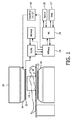
図1は、本発明が使用される医療撮像システム、この場合には、磁気共鳴撮像(MRI)システムを図式的に示す。前記MRIシステムは、検査ゾーン14内に静止一様主磁場を生成する主磁石10を有する。この主磁場は、前記主磁場の力線に沿った検査対象内のスピンの部分配向を引き起こす。RFシステムは、前記検査対象の体内のスピンを励起するように前記検査ゾーン内にRF励起電磁場を発する1以上のRFアンテナ12を備える。緩和するスピンは、RF範囲において磁気共鳴信号を発し、前記磁気共鳴信号は、特にRF受信コイルの形の、RFアンテナ12により取得される。更に、勾配コイル16は、一時的な勾配磁場、特に読み出し勾配パルス及び位相エンコード勾配を生成するように提供される。これらの勾配磁場は、通常、相互に直交する方向に配向され、前記磁気共鳴信号に空間エンコードをかける。勾配増幅器(GradAmp(x,y,z))18は、勾配エンコード磁場を生成するように勾配コイル16を起動するように提供される。RF受信器アンテナ12により取得された前記磁気共鳴信号は、分光計を有するMRIデータ取得(MRIacq)19システムに加えられる。前記MRIデータ取得システムは、このデータをホストコンピュータ(HC)20に提供し、ホストコンピュータ20は、これを再構成器(Recon)22に提供し、再構成器22は、前記データから画像を再構成する。前記ホストコンピュータは、以下に記載される方法ステップを実行するように構成されるコンピュータプログラムを更に有することができる。
FIG. 1 schematically shows a medical imaging system in which the present invention is used, in this case a magnetic resonance imaging (MRI) system. The MRI system has a
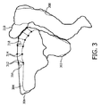
図2は、本発明による方法を図式的に示す。図2は、フローチャートである。前記方法は、図3に示される例を用いて更に説明される。図3は、第1の医療画像及び第2の医療画像に基づいて治療目標及びリスク臓器のセグメンテーションを図式的に示す。 FIG. 2 shows diagrammatically the method according to the invention. FIG. 2 is a flowchart. The method is further explained using the example shown in FIG. FIG. 3 diagrammatically shows the segmentation of treatment targets and risk organs based on the first medical image and the second medical image.
本発明の実施例による前記方法は、放射線治療分割部分時間間隔にわたって行われる放射線治療分割部分の間に予期される局所的な分割部分内運動を補償するために治療目標302(図3)及び/又はリスク臓器304、308(図3)に対する患者特有の局所的に変化するマージンを決定する方法である。前記放射線治療時間間隔は、治療される器官及び放射線治療計画の複雑さに依存する。前記治療される器官は、事前に既知であり、前記臨床医は、前記計画(例えばコンフォーマル、強度変調放射線治療、VMAT)の所望の複雑さについて事前に決定することができる。したがって、前記放射線治療時間間隔は、前記放射線治療計画の実際の作成の前に予測可能である。前立腺がん治療に対して、前記放射線治療時間間隔は、最近、ほとんどの場合に、5乃至15分である。前記患者特有の局所的に変化するマージンは、前記治療目標及び/又はリスク臓器における少なくとも第1の場所312(図3)及び第2の場所314(図3)の変位及び/又は前記変位の推定に基づいて決定される。前記患者特有の局所的に変化するマージンを決定する方法は、以下のステップを有する。
‐前記治療目標及び/又はリスク臓器の第1の医療画像を取得するステップ201。前記第1の医療画像は、例えばUTE−DIXON MRI又はT1−DIXON画像であることができる。このUTE−DIXON画像は、ステップ208において、疑似CT又は減衰マップを生成するのに使用されることができる。前記疑似CT又は減衰マップは、放射線治療計画の計算208に対する入力として機能することができる。
‐前記治療目標及び/又はリスク臓器の第2の医療画像を取得するステップ202。前記第1の医療画像及び前記第2の医療画像の取得の間の時間は、放射線治療分割部分時間間隔と同様である。前立腺の場合、前記第1の医療画像及び前記第2の医療画像の取得の間の時間は、5乃至15分のオーダである。前記第2の医療画像は、T2w MRI画像であることができる。このT2w画像は、治療目標体積の輪郭を描く209ために臨床医により使用されることができる。治療目的は、前記治療目標に対して設定される。前記輪郭を描かれた治療目標及びその治療目的は、放射線治療計画の計算207に対する入力として機能する。
‐前記第1の医療画像及び前記第2の医療画像における第1の場所312(図3)及び第2の場所314(図3)の位置を決定するステップ203。前記第1の場所及び第2の場所は、関心構造の周りの輪郭線304(図3)上に配置されることができるが、個別のランドマークであることもできる。好ましくは、1以上の関心構造のセグメンテーションは、前記第1の場所、第2の場所及び他の場所を識別するのに使用され、図3に見られるように、膀胱304、前立腺302及び直腸308は、前記第1の医療画像に基づいてセグメント化される。図3における輪郭306及び310は、前記第2の医療画像における位置及び形状に基づいて、それぞれ膀胱及び腸のセグメンテーションを表す。
‐前記治療目標及び/又はリスク臓器の周りの患者特有の局所的に変化するマージン316、318を決定するのに前記決定された位置を使用するステップ204。これは、例えば、第1の輪郭と第2の輪郭との間の距離及びその内挿又は外挿バージョンであることができる。また、前記患者特有の局所的に変化するマージンは、前記第1の場所及び第2の場所を有する第1の殻(hull)と、前記第1及び第2の場所を有する第2の殻との間の距離であることができる。与えられた例において、前記マージンは、三角化表面メッシュのアンカポイント上に規定され、事実上、前記構造の周りで連続的に変化する。
‐前記患者特有の局所的に変化するマージンを使用して放射線治療計画を計算するステップ207。
The method according to an embodiment of the present invention includes a treatment target 302 (FIG. 3) and/or treatment target 302 (FIG. 3) to compensate for expected local intra-segmental motion during the radiotherapy fractions performed over the radiotherapy fractional time interval. Alternatively, it is a method of determining a patient-specific locally varying margin for the
-Obtaining 201 a first medical image of said treatment goal and/or risk organ. The first medical image can be, for example, a UTE-DIXON MRI or T1-DIXON image. This UTE-DIXON image can be used in
-Obtaining 202 a second medical image of the treatment goal and/or the risk organ. The time between the acquisition of the first medical image and the second medical image is similar to the radiotherapy split partial time interval. In the case of the prostate, the time between the acquisition of the first medical image and the second medical image is on the order of 5 to 15 minutes. The second medical image can be a T2w MRI image. This T2w image can be used by the clinician to delineate 209 the treatment target volume. The treatment objective is set with respect to the treatment objective. The outlined treatment goals and their treatment goals serve as inputs to the radiation
-Determining 203 the position of a first location 312 (Fig. 3) and a second location 314 (Fig. 3) in the first medical image and the second medical image. The first location and the second location can be located on the contour line 304 (FIG. 3) around the structure of interest, but can also be individual landmarks. Preferably, segmentation of one or more structures of interest is used to identify the first location, the second location and other locations, as seen in FIG. 3, the
-Using 204 the determined position to determine patient-specific locally varying
Calculating 207 a radiation treatment plan using the patient-specific locally varying margin.
前記第1の場所、第2の場所及びオプションとして他の場所の変位は、多くの異なる形でユーザに表示されることができる。図4は、前記第1の場所、第2の場所及びオプションとして他の場所の変位がユーザに表示されることができる方法の少数の例を示す。例えば、前記変位は、2つのセグメンテーションのオーバレイにより表示されることができる402。代わりに、変位ベクトルが、前記ユーザに表示されることができる404。また、線の太さが、変位の程度を示すように変化されることができる406。 The displacements of the first location, the second location and optionally other locations can be displayed to the user in many different ways. FIG. 4 shows a few examples of how the displacements of the first location, the second location and optionally other locations can be displayed to the user. For example, the displacement may be displayed 402 with an overlay of two segmentations. Alternatively, the displacement vector can be displayed 404 to the user. Also, the thickness of the line can be changed 406 to indicate the degree of displacement.
図5は、輪郭502、506の内挿及び外挿が前記ユーザに表示されることができる方法の一例を図式的に示す。この例において、スライダ502が、提供され、これを用いて、前記ユーザは、どの内挿又は外挿輪郭を見ることを望むかを示されることができる。50%におけるスライダ位置504は、輪郭502を示す。120%におけるスライダ位置508は、輪郭506を示す。前記ユーザは、分割部分内運動を補償するために治療中にこれらのマージンのいずれを使用することを望むかを決定するのに、この情報を使用することができる。また、前記ユーザは、単一の分割部分の間に複数のマージンを使用することを決定してもよい。例えば、前記ユーザは、0%輪郭よりわずかに大きい分割部分内運動を補償するマージンで開始することができ、前記分割部分内の後で、前記分割部分内運動を補償するマージンは、50%よりわずかに大きく設定されることができ、前記分割部分の終了に向けて、前記マージンは、100%よりわずかに大きく設定されることができる。これらの値は、純粋に例であり、他の値が、同様に選択されることができる。これらの複数のマージンは、前記放射線治療計画に組み込まれることができる。
FIG. 5 schematically shows an example of how the interpolation and extrapolation of
本発明は、図面及び先行する記載において詳細に図示及び記載されているが、このような図示及び記載は、限定的ではなく、例示的又は典型的であると見なされるべきであり、本発明は、開示された実施例に限定されない。 While the present invention has been illustrated and described in detail in the drawings and foregoing description, such illustration and description are to be considered illustrative or exemplary and not restrictive, and It is not limited to the disclosed embodiments.
Claims (14)
画像取得手段が、前記治療目標及び/又はリスク臓器の第1の医療画像を取得するステップであって、前記第1の医療画像が、前記治療目標の疑似CT画像の生成に対して使用されるのに適したMRI画像である、ステップと、
画像取得手段が、前記治療目標及び/又は前記リスク臓器の第2の医療画像を取得するステップであって、前記第1の医療画像及び前記第2の医療画像の取得の間の時間が、前記分割照射の前記照射時間と同様である、ステップと、
コンピュータが、前記第1の医療画像及び前記第2の医療画像において前記第1の場所及び前記第2の場所の位置を決定するステップと、
コンピュータが、前記治療目標及び/又はリスク臓器の周りの前記患者特有の局所的に変化するマージンを決定するのに前記決定された位置を使用するステップと、
を有する、
作動方法。 Method of operating a medical imaging system to determine the margin for locally varying patient-specific with respect to the treatment target and / or organs at risk in order to compensate for the anticipated local movements during fractionated irradiation radiological treatment, the The fractionated irradiation is performed over the irradiation time of the fractionated irradiation, and the patient-specific locally varying margin is at least a first location and a second location displacement and/or a displacement on the treatment target and/or the risk organ. Or determined based on the estimation for the displacement, the operating method,
Image acquisition means acquiring a first medical image of the treatment target and/or the risk organ, wherein the first medical image is used for generating a pseudo CT image of the treatment target. An MRI image suitable for
Image obtaining means, a second step of acquiring medical image of the treatment target and / or the organs at risk, the time between the acquisition of the first medical image and the second medical image, wherein The same as the irradiation time of divided irradiation , a step,
A computer determining the position of the first location and the second location in the first medical image and the second medical image;
A computer using the determined location to determine the patient-specific locally varying margin around the treatment goal and/or risk organ;
Have
How it works .
第1の医療画像及び第2の医療画像において治療目標及び/又はリスク臓器上の第1の場所及び第2の場所の位置を決定するステップであって、前記第1の医療画像が、前記治療目標の疑似CT画像の生成に対して使用されるのに適したMRI画像であり、前記第1の医療画像及び前記第2の医療画像の取得の間の時間が、前記分割照射の前記照射時間と同様である、ステップと、
前記治療目標及び/又はリスク臓器の周りの前記患者特有の局所的に変化するマージンを決定するのに前記決定された位置を使用するステップと、
をコンピュータに実行させるプログラムコード手段を有する、コンピュータプログラム。 A computer program for determining a locally varying margin of the patient-specific about the therapeutic goal and / or organs at risk in order to compensate for the anticipated local movements of rays in the treatment of fractionated radiation release, the divided irradiation Is performed over the irradiation time of the fractionated irradiation, and the patient-specific locally varying margin is at least a first location and a second location displacement on the treatment goal and/or risk organ and/or the Determined based on an estimate for displacement, the computer program
Determining the location of a first location and a second location on a treatment target and/or a risk organ in the first medical image and the second medical image, wherein the first medical image is the treatment. An MRI image suitable for use in generating a target pseudo-CT image, wherein the time between acquisition of the first medical image and the second medical image is the irradiation time of the fractionated irradiation. And a step similar to
Using the determined position to determine the patient-specific locally varying margin around the treatment goal and/or risk organ;
A computer program having program code means for causing a computer to execute.
前記治療目標及び/又はリスク臓器の前記第2の医療画像を取得するステップであって、前記第1の医療画像及び前記第2の医療画像の取得の間の時間が、前記分割照射の前記照射時間と同様である、ステップと、
をコンピュータに実行させるプログラムコード手段を有する、請求項11に記載のコンピュータプログラム。 Acquiring the first image of the treatment goal and/or the risk organ,
The step of acquiring the second medical image of the treatment target and/or the risk organ, wherein the time between the acquisition of the first medical image and the second medical image is the irradiation of the divided irradiation. Steps, similar to time ,
The computer program according to claim 11, comprising program code means for causing a computer to execute.
Applications Claiming Priority (3)
| Application Number | Priority Date | Filing Date | Title |
|---|---|---|---|
| EP15201291 | 2015-12-18 | ||
| EP15201291.0 | 2015-12-18 | ||
| PCT/EP2016/081620 WO2017103237A1 (en) | 2015-12-18 | 2016-12-16 | Method for determining a patient specific locally varying margin |
Publications (3)
| Publication Number | Publication Date |
|---|---|
| JP2019500099A JP2019500099A (en) | 2019-01-10 |
| JP2019500099A5 JP2019500099A5 (en) | 2019-11-14 |
| JP6748207B2 true JP6748207B2 (en) | 2020-08-26 |
Family
ID=54979481
Family Applications (1)
| Application Number | Title | Priority Date | Filing Date |
|---|---|---|---|
| JP2018529276A Active JP6748207B2 (en) | 2015-12-18 | 2016-12-16 | How to determine patient-specific locally changing margins |
Country Status (5)
| Country | Link |
|---|---|
| US (1) | US10792515B2 (en) |
| EP (1) | EP3389780B1 (en) |
| JP (1) | JP6748207B2 (en) |
| CN (1) | CN108430578B (en) |
| WO (1) | WO2017103237A1 (en) |
Families Citing this family (2)
| Publication number | Priority date | Publication date | Assignee | Title |
|---|---|---|---|---|
| JP7092745B2 (en) * | 2016-08-11 | 2022-06-28 | コーニンクレッカ フィリップス エヌ ヴェ | Medical products configured for use in image-based radiation therapy planning |
| GB2598127B (en) * | 2020-08-19 | 2022-08-10 | Elekta ltd | Control of a radiotherapy device |
Family Cites Families (15)
| Publication number | Priority date | Publication date | Assignee | Title |
|---|---|---|---|---|
| US20040073833A1 (en) * | 2002-10-10 | 2004-04-15 | Sun Microsystems, Inc. | Apparatus and methods for redundant management of computer systems |
| JP5122816B2 (en) * | 2003-09-30 | 2013-01-16 | コーニンクレッカ フィリップス エレクトロニクス エヌ ヴィ | Target tracking method and apparatus for radiation therapy planning and implementation |
| CA2974143C (en) | 2004-02-20 | 2020-11-10 | University Of Florida Research Foundation, Inc. | System for delivering conformal radiation therapy while simultaneously imaging soft tissue |
| US7532705B2 (en) * | 2006-04-10 | 2009-05-12 | Duke University | Systems and methods for localizing a target for radiotherapy based on digital tomosynthesis |
| US20070286342A1 (en) * | 2006-06-07 | 2007-12-13 | Fuller Donald B | Systems and methods for performing radiosurgery using stereotactic techniques |
| US7609810B2 (en) | 2006-12-14 | 2009-10-27 | Byong Yong Yi | Treatment-speed regulated tumor-tracking |
| EP2214582A2 (en) * | 2007-10-25 | 2010-08-11 | Tomotherapy Incorporated | Method for adapting fractionation of a radiation therapy dose |
| CN102656607B (en) * | 2009-12-16 | 2015-11-25 | 皇家飞利浦电子股份有限公司 | The target developing new optimization is collected in application plan |
| DE102011076771A1 (en) | 2011-04-15 | 2012-10-18 | Siemens Aktiengesellschaft | Method and device for radiation planning |
| EP2854946B1 (en) * | 2012-05-29 | 2017-07-12 | Koninklijke Philips N.V. | Elasticity imaging-based planning systems for improved gating efficiency and dynamic margin adjustment in radiation therapy |
| CN103678837A (en) * | 2012-08-31 | 2014-03-26 | 西门子公司 | Method and device for determining processing remains of target area |
| US9649508B2 (en) * | 2012-09-13 | 2017-05-16 | Emory University | Methods, systems and computer readable storage media storing instructions for determining patient specific treatment planning margins |
| CN106133790B (en) * | 2014-03-28 | 2020-09-29 | 皇家飞利浦有限公司 | Method and device for generating one or more computed tomography images based on magnetic resonance images with the aid of tissue type separation |
| US10307108B2 (en) * | 2015-10-13 | 2019-06-04 | Elekta, Inc. | Pseudo-CT generation from MR data using a feature regression model |
| US10102451B2 (en) * | 2015-10-13 | 2018-10-16 | Elekta, Inc. | Pseudo-CT generation from MR data using tissue parameter estimation |
-
2016
- 2016-12-16 CN CN201680073391.7A patent/CN108430578B/en active Active
- 2016-12-16 JP JP2018529276A patent/JP6748207B2/en active Active
- 2016-12-16 US US15/775,021 patent/US10792515B2/en active Active
- 2016-12-16 EP EP16822441.8A patent/EP3389780B1/en active Active
- 2016-12-16 WO PCT/EP2016/081620 patent/WO2017103237A1/en active Application Filing
Also Published As
| Publication number | Publication date |
|---|---|
| CN108430578A (en) | 2018-08-21 |
| US10792515B2 (en) | 2020-10-06 |
| EP3389780A1 (en) | 2018-10-24 |
| US20180318604A1 (en) | 2018-11-08 |
| EP3389780B1 (en) | 2019-10-23 |
| WO2017103237A1 (en) | 2017-06-22 |
| CN108430578B (en) | 2020-12-01 |
| JP2019500099A (en) | 2019-01-10 |
Similar Documents
| Publication | Publication Date | Title |
|---|---|---|
| Zachiu et al. | An improved optical flow tracking technique for real-time MR-guided beam therapies in moving organs | |
| JP6142073B2 (en) | Radiotherapy system with real-time magnetic resonance monitoring | |
| Lagendijk et al. | MR guidance in radiotherapy | |
| JP6169573B2 (en) | Reduction of radio frequency transmission field within a given volume during magnetic resonance imaging | |
| Hu et al. | Respiratory amplitude guided 4-dimensional magnetic resonance imaging | |
| Nyholm et al. | Counterpoint: opportunities and challenges of a magnetic resonance imaging–only radiotherapy work flow | |
| Alterovitz et al. | Registration of MR prostate images with biomechanical modeling and nonlinear parameter estimation | |
| de Senneville et al. | A direct PCA-based approach for real-time description of physiological organ deformations | |
| JP6387108B2 (en) | Method for estimating pseudo CT house field unit value, magnetic resonance system and computer program | |
| Du et al. | High-quality T2-weighted 4-dimensional magnetic resonance imaging for radiation therapy applications | |
| Doemer et al. | Evaluating organ delineation, dose calculation and daily localization in an open-MRI simulation workflow for prostate cancer patients | |
| WO2008014340A2 (en) | Prediction and treatment of brain tumor spread using mri and external beam radiation | |
| JP6748207B2 (en) | How to determine patient-specific locally changing margins | |
| JP6873238B2 (en) | Optimizing time-synchronized deep brain stimulation | |
| Huttinga et al. | Real-time myocardial landmark tracking for MRI-guided cardiac radio-ablation using Gaussian Processes | |
| US11883127B2 (en) | Method and magnetic resonance apparatus for synchronous imaging and radiation therapy | |
| CN112384279B (en) | Treatment planning device | |
| Beld et al. | MRI artifact simulation for clinically relevant MRI sequences for guidance of prostate HDR brachytherapy | |
| Morris et al. | Quantifying inter-fraction cardiac substructure displacement during radiotherapy via magnetic resonance imaging guidance | |
| JP6637216B2 (en) | Magnetic resonance imaging guided treatment system | |
| EP3422037A1 (en) | Method and device for determining a motion field from k-space data | |
| Tanaka et al. | Fiducial marker for prostate radiotherapy: comparison of 0.35-and 0.5-mm-diameter computed tomography and magnetic resonance images | |
| US20220283251A1 (en) | Simultaneous Multi-Orientation Magnetic Resonance Imaging | |
| JP2021518222A (en) | (3-n) dimension identification of conductivity | |
| Brown | Estimating 3D Deformable Motion from a series of Fast 2D MRI Images |
Legal Events
| Date | Code | Title | Description |
|---|---|---|---|
| A521 | Request for written amendment filed |
Free format text: JAPANESE INTERMEDIATE CODE: A523 Effective date: 20191004 |
|
| A621 | Written request for application examination |
Free format text: JAPANESE INTERMEDIATE CODE: A621 Effective date: 20191004 |
|
| A871 | Explanation of circumstances concerning accelerated examination |
Free format text: JAPANESE INTERMEDIATE CODE: A871 Effective date: 20191004 |
|
| A975 | Report on accelerated examination |
Free format text: JAPANESE INTERMEDIATE CODE: A971005 Effective date: 20191203 |
|
| A131 | Notification of reasons for refusal |
Free format text: JAPANESE INTERMEDIATE CODE: A131 Effective date: 20191210 |
|
| A601 | Written request for extension of time |
Free format text: JAPANESE INTERMEDIATE CODE: A601 Effective date: 20200309 |
|
| A521 | Request for written amendment filed |
Free format text: JAPANESE INTERMEDIATE CODE: A523 Effective date: 20200610 |
|
| TRDD | Decision of grant or rejection written | ||
| A01 | Written decision to grant a patent or to grant a registration (utility model) |
Free format text: JAPANESE INTERMEDIATE CODE: A01 Effective date: 20200721 |
|
| A61 | First payment of annual fees (during grant procedure) |
Free format text: JAPANESE INTERMEDIATE CODE: A61 Effective date: 20200806 |
|
| R150 | Certificate of patent or registration of utility model |
Ref document number: 6748207 Country of ref document: JP Free format text: JAPANESE INTERMEDIATE CODE: R150 |
|
| R250 | Receipt of annual fees |
Free format text: JAPANESE INTERMEDIATE CODE: R250 |