JP6747060B2 - Information processing equipment - Google Patents
Information processing equipment Download PDFInfo
- Publication number
- JP6747060B2 JP6747060B2 JP2016106818A JP2016106818A JP6747060B2 JP 6747060 B2 JP6747060 B2 JP 6747060B2 JP 2016106818 A JP2016106818 A JP 2016106818A JP 2016106818 A JP2016106818 A JP 2016106818A JP 6747060 B2 JP6747060 B2 JP 6747060B2
- Authority
- JP
- Japan
- Prior art keywords
- value
- power
- correction coefficient
- sensor
- instruction
- Prior art date
- Legal status (The legal status is an assumption and is not a legal conclusion. Google has not performed a legal analysis and makes no representation as to the accuracy of the status listed.)
- Active
Links
Images


Classifications
-
- Y—GENERAL TAGGING OF NEW TECHNOLOGICAL DEVELOPMENTS; GENERAL TAGGING OF CROSS-SECTIONAL TECHNOLOGIES SPANNING OVER SEVERAL SECTIONS OF THE IPC; TECHNICAL SUBJECTS COVERED BY FORMER USPC CROSS-REFERENCE ART COLLECTIONS [XRACs] AND DIGESTS
- Y02—TECHNOLOGIES OR APPLICATIONS FOR MITIGATION OR ADAPTATION AGAINST CLIMATE CHANGE
- Y02T—CLIMATE CHANGE MITIGATION TECHNOLOGIES RELATED TO TRANSPORTATION
- Y02T10/00—Road transport of goods or passengers
- Y02T10/60—Other road transportation technologies with climate change mitigation effect
- Y02T10/70—Energy storage systems for electromobility, e.g. batteries
Description
本発明は、電力調整システム、情報処理装置、情報処理方法、およびプログラムに関し、特に、エネルギー関連装置から入出力される電力を調整する電力調整システム、情報処理装置、情報処理方法、およびプログラムに関する。 The present invention relates to a power adjustment system, an information processing device, an information processing method, and a program, and more particularly, to a power adjustment system, an information processing device, an information processing method, and a program that adjust the power input/output from an energy-related device.
蓄電池の充放電を制御する電力制御装置の一例が特許文献1に記載されている。特許文献1の電力制御装置は、電力系統からの交流電力および蓄電池からの直流電力の一方を優先的に用いて車載電池に充電する。
また、特許文献2に記載には、電力システムの性能を監視する制御装置の較正システムが記載されている。較正システムは、制御装置の較正中に使用される高精度電力計を具現する。較正システムのプロセッサは、較正時に、試験電圧を有する電力を源から制御装置に導き、第1の試験電圧に対応する少なくとも一つの出力の値と、測定されたパラメータの値をオフセット誤差に直接関係付けるように構成されている。 Further, Patent Document 2 describes a calibration system of a control device that monitors the performance of a power system. The calibration system embodies a precision power meter used during controller calibration. During calibration, the calibration system processor directs power having a test voltage from the source to the controller during calibration, and directly relates the value of the at least one output corresponding to the first test voltage and the value of the measured parameter to the offset error. Is configured to attach.
たとえば、需要家の蓄電池を用いて、電力系統向けの短周期調整力サービス(ガバナフリーや負荷周波数制御)等を行う場合、蓄電池の充放電制御の精度が求められる。
電力系統と負荷の間の電力ラインに蓄電池から入出力される電力制御を行うPCS(Power Conditioner System)は、指示値に従い出力制御を行うが、指示値とPCSからの出力値とが異なる状況が発生し得る。これは需給調整に影響を及ぼす可能性があり、サービスの信頼度等の点で好ましくない。
For example, when performing a short cycle adjustment service (governor-free or load frequency control) for a power system using a storage battery of a consumer, accuracy of charge/discharge control of the storage battery is required.
A PCS (Power Conditioner System) that controls the electric power input and output from the storage battery in the electric power line between the electric power system and the load performs output control according to the instruction value, but there is a situation where the instruction value and the output value from the PCS are different. Can occur. This may affect supply and demand adjustment and is not preferable in terms of service reliability.
本発明は上記事情に鑑みてなされたものであり、その目的とするところは、需要家において高精度な電力調整を実現する需給調整システム、情報処理装置、その情報処理方法、およびプログラムを提供することにある。 The present invention has been made in view of the above circumstances, and an object of the present invention is to provide a supply and demand adjustment system, an information processing device, an information processing method thereof, and a program that realize highly accurate power adjustment in a consumer. Especially.
本発明の各側面では、上述した課題を解決するために、それぞれ以下の構成を採用する。 In each aspect of the present invention, the following configurations are adopted to solve the above-mentioned problems.
第一の側面は、情報処理装置に関する。
第一の側面に係る第1の情報処理装置は、
電力系統と負荷の間の電力ラインに流れる電力に関する計測値を取得する計測値取得手段と、
蓄電装置から前記電力ラインに入出力すべき電力を示す指示値を取得する指示値取得手段と、
前記指示値に従い前記蓄電装置から入出力される電力が制御されて前記電力ラインに入出力されたとき、前記計測値が、対応する前記指示値になるように、前記指示値を補正する補正係数を算出する算出手段と、を有し、
前記算出手段は、所定期間毎に前記補正係数を算出し、
前記計測値取得手段は、前記計測値として、前記電力ラインに入出力される前記電力の積算電力量を計測する第1の電力量計から所定期間毎の前記積算電力量を取得し、
前記算出手段は、前記積算電力量が所定値を超えた場合に、前記積算電力量と、前記指示値を前記所定期間、積算した積算指示値とが所定の関係を満たす補正係数を求める。
第一の側面に係る第2の情報処理装置は、
電力系統と負荷の間の電力ラインに流れる電力に関する計測値を取得する計測値取得手段と、
蓄電装置から前記電力ラインに入出力すべき電力を示す指示値を取得する指示値取得手段と、
前記指示値に従い前記蓄電装置から入出力される電力が制御されて前記電力ラインに入出力されたとき、前記計測値が対応する前記指示値になるように、前記指示値を補正する補正係数を算出する算出手段と、を有し、
前記計測値取得手段は、前記電力ラインに入出力される前記電力の電力瞬時値を計測する第1の電力量計から前記計測値として少なくとも一つの前記電力瞬時値を取得し、
前記指示値取得手段は、前記計測値取得手段が少なくとも一つの前記電力瞬時値を取得した時の少なくとも一つの前記指示値を取得し、
前記算出手段は、前記第1の電力量計から取得した少なくとも一つの前記電力瞬時値、および当該電力瞬時値に対応する前記指示値を用いて前記補正係数を算出し、
前記算出手段は、
前記第1の電力量計から取得した複数の前記電力瞬時値の平均値と、複数の前記指示値の平均値とが所定の関係を満たす前記補正係数を求める。
第一の側面に係る第3の情報処理装置は、
電力系統と負荷の間の電力ラインに流れる電力に関する計測値を取得する計測値取得手段と、
蓄電装置から前記電力ラインに入出力すべき電力を示す指示値を取得する指示値取得手段と、
前記指示値に従い前記蓄電装置から入出力される電力が制御されて前記電力ラインに入出力されたとき、前記計測値が対応する前記指示値になるように、前記指示値を補正する補正係数を算出する算出手段と、を有し、
前記計測値取得手段は、前記電力ラインに入出力される前記電力の電力瞬時値を計測する第1の電力量計から前記計測値として少なくとも一つの前記電力瞬時値を取得し、
前記指示値取得手段は、前記計測値取得手段が少なくとも一つの前記電力瞬時値を取得した時の少なくとも一つの前記指示値を取得し、
前記算出手段は、前記第1の電力量計から取得した少なくとも一つの前記電力瞬時値、および当該電力瞬時値に対応する前記指示値を用いて前記補正係数を算出し、
前記算出手段は、
前記第1の電力量計から取得した複数の前記電力瞬時値の積算値と、複数の前記指示値の積算値とが所定の関係を満たす前記補正係数を求める。
第一の側面に係る第4の情報処理装置は、
電力系統と負荷の間の電力ラインに流れる電力に関する計測値を取得する計測値取得手段と、
蓄電装置から前記電力ラインに入出力すべき電力を示す指示値を取得する指示値取得手段と、
前記指示値に従い前記蓄電装置から入出力される電力が制御されて前記電力ラインに入出力されたとき、前記計測値が対応する前記指示値になるように、前記指示値を補正する補正係数を算出する算出手段と、を有し、
前記電力ラインと、前記蓄電装置との間に電気的に接続される制御装置が、前記指示値に従い制御した電力を前記電力ラインに入出力し、
前記電力ラインは、前記電力系統と前記制御装置の間の第1電力ラインと前記制御装置と前記負荷の間の第2電力ラインを含み、
前記計測値取得手段は、前記第1電力ラインの電力瞬時値を計測する第1センサと、前記第2電力ラインの電力瞬時値を計測する第2センサから、前記第1センサと前記第2センサの各々について少なくとも一つの電力瞬時値を前記計測値としてそれぞれ取得し、
前記指示値取得手段は、前記第1センサおよび前記第2センサの各々について少なくとも一つの前記計測値を取得した時の少なくとも一つの前記指示値を取得し、
前記算出手段は、
前記第1センサおよび前記第2センサの各々について少なくとも一つの前記電力瞬時値と、当該計測値に対応する前記指示値とを用いて前記補正係数を算出する。
第一の側面に係る第5の情報処理装置は、
電力系統と負荷の間の電力ラインに流れる電力に関する計測値を取得する計測値取得手段と、
蓄電装置から前記電力ラインに入出力すべき電力を示す指示値を取得する指示値取得手段と、
前記指示値に従い前記蓄電装置から入出力される電力が制御されて前記電力ラインに入出力されたとき、前記計測値が対応する前記指示値になるように、前記指示値を補正する補正係数を算出する算出手段と、を有し、
前記電力ラインと、前記蓄電装置との間に電気的に接続される制御装置が、前記指示値に従い制御した電力を前記電力ラインに入出力し、
前記電力ラインは、前記電力系統と前記制御装置の間の第1電力ラインと前記制御装置と前記負荷の間の第2電力ラインを含み、
前記計測値取得手段が、前記電力系統から前記電力ラインに供給される電力を計測する第2の電力量計と、前記第2電力ラインの電力瞬時値を計測する第2センサから電力瞬時値を前記計測値としてそれぞれ少なくとも一つずつ取得し、
前記指示値取得手段は、前記第2の電力量計および前記第2センサの各々について少なくとも一つの前記計測値を取得した時の前記指示値を取得し、
前記算出手段は、
前記第2の電力量計および前記第2センサの各々について少なくとも一つの前記電力瞬時値と、少なくとも一つの前記計測値に対応する前記指示値とを用いて前記補正係数を算出する。
The first aspect relates to an information processing device.
The first information processing apparatus according to the first aspect is
A measurement value acquisition unit that acquires a measurement value related to the power flowing in the power line between the power system and the load,
An instruction value acquisition unit that acquires an instruction value indicating the electric power to be input to and output from the power storage device,
A correction coefficient for correcting the instruction value so that the measured value becomes the corresponding instruction value when the electric power input/output from the power storage device is controlled according to the instruction value and input/output to/from the power line. have a, a calculation means for calculating,
The calculation means calculates the correction coefficient every predetermined period,
The measurement value acquisition means acquires, as the measurement value, the integrated power amount for each predetermined period from a first watt-hour meter that measures an integrated power amount of the power input to and output from the power line,
Said calculation means, when the accumulated electric power amount exceeds the predetermined value, and the integral power consumption, the said indication value predetermined period, the cumulated integrated reading is Ru obtain correction coefficient that satisfies a predetermined relationship.
The second information processing apparatus according to the first aspect,
A measurement value acquisition unit that acquires a measurement value related to the power flowing in the power line between the power system and the load,
An instruction value acquisition unit that acquires an instruction value indicating the electric power to be input to and output from the power storage device,
When the electric power input/output from the power storage device is controlled according to the instruction value and input/output to/from the power line, a correction coefficient for correcting the instruction value is set so that the measured value becomes the corresponding instruction value. And a calculating means for calculating,
The measurement value acquisition unit acquires at least one power instantaneous value as the measurement value from a first watt hour meter that measures a power instantaneous value of the power input to and output from the power line,
The instruction value acquisition means acquires at least one instruction value when the measurement value acquisition means acquires at least one of the power instantaneous values,
The calculation means calculates the correction coefficient using at least one of the power instantaneous value acquired from the first watt hour meter, and the instruction value corresponding to the power instantaneous value,
The calculation means is
The correction coefficient satisfying a predetermined relationship between the average value of the plurality of instantaneous power values acquired from the first watt-hour meter and the average value of the plurality of instruction values is obtained.
A third information processing apparatus according to the first aspect is
A measurement value acquisition unit that acquires a measurement value related to the power flowing in the power line between the power system and the load,
An instruction value acquisition unit that acquires an instruction value indicating the electric power to be input to and output from the power storage device,
When the electric power input/output from the power storage device is controlled according to the instruction value and input/output to/from the power line, a correction coefficient for correcting the instruction value is set so that the measured value becomes the corresponding instruction value. And a calculating means for calculating,
The measurement value acquisition unit acquires at least one power instantaneous value as the measurement value from a first watt hour meter that measures a power instantaneous value of the power input to and output from the power line,
The instruction value acquisition means acquires at least one instruction value when the measurement value acquisition means acquires at least one of the power instantaneous values,
The calculation means calculates the correction coefficient using at least one of the power instantaneous value acquired from the first watt hour meter, and the instruction value corresponding to the power instantaneous value,
The calculation means is
The correction coefficient that satisfies a predetermined relationship between the integrated value of the plurality of instantaneous power values acquired from the first watt-hour meter and the integrated value of the plurality of instruction values is obtained.
A fourth information processing apparatus according to the first aspect is
A measurement value acquisition unit that acquires a measurement value related to the power flowing in the power line between the power system and the load,
An instruction value acquisition unit that acquires an instruction value indicating the electric power to be input to and output from the power storage device,
When the electric power input/output from the power storage device is controlled according to the instruction value and input/output to/from the power line, a correction coefficient for correcting the instruction value is set so that the measured value becomes the corresponding instruction value. And a calculating means for calculating,
A control device electrically connected between the power line and the power storage device inputs and outputs power controlled according to the instruction value to the power line,
The power line includes a first power line between the power system and the control device, and a second power line between the control device and the load,
The measurement value acquisition means includes a first sensor that measures an instantaneous power value of the first power line and a second sensor that measures an instantaneous power value of the second power line, and the first sensor and the second sensor. For each of at least one instantaneous power value is obtained as the measured value,
The instruction value acquisition means acquires at least one of the instruction values when acquiring at least one of the measurement values for each of the first sensor and the second sensor,
The calculation means is
The correction coefficient is calculated using at least one instantaneous electric power value for each of the first sensor and the second sensor and the instruction value corresponding to the measured value.
A fifth information processing apparatus according to the first aspect is
A measurement value acquisition unit that acquires a measurement value related to the power flowing in the power line between the power system and the load,
An instruction value acquisition unit that acquires an instruction value indicating the power to be input to and output from the power storage device on the power line,
When the electric power input/output from the power storage device is controlled according to the instruction value and input/output to/from the power line, a correction coefficient for correcting the instruction value is set so that the measured value becomes the corresponding instruction value. And a calculating means for calculating,
A control device electrically connected between the power line and the power storage device inputs and outputs power controlled according to the instruction value to the power line,
The power line includes a first power line between the power system and the control device, and a second power line between the control device and the load,
The measurement value acquisition means measures a power instantaneous value from a second watt-hour meter that measures the power supplied from the power system to the power line and a second sensor that measures the power instantaneous value of the second power line. Obtain at least one each as the measurement value,
The instruction value acquisition means acquires the instruction value when at least one of the measurement values is acquired for each of the second electric energy meter and the second sensor,
The calculation means is
The correction coefficient is calculated using at least one instantaneous electric power value and the indicated value corresponding to at least one measured value for each of the second watt-hour meter and the second sensor.
なお、以上の構成要素の任意の組合せ、本発明の表現を方法、装置、システム、記録媒体、コンピュータプログラムなどの間で変換したものもまた、本発明の態様として有効である。 It should be noted that any combination of the above constituent elements, and the expression of the present invention converted between a method, an apparatus, a system, a recording medium, a computer program, etc. are also effective as an aspect of the present invention.
また、本発明の各種の構成要素は、必ずしも個々に独立した存在である必要はなく、複数の構成要素が一個の部材として形成されていること、一つの構成要素が複数の部材で形成されていること、ある構成要素が他の構成要素の一部であること、ある構成要素の一部と他の構成要素の一部とが重複していること、等でもよい。 Further, the various constituent elements of the present invention do not necessarily have to be independently present, and a plurality of constituent elements are formed as one member, and one constituent element is formed by a plurality of members. May be present, a certain component may be a part of another component, a part of a certain component may overlap a part of another component, and the like.
また、本発明の方法およびコンピュータプログラムには複数の手順を順番に記載してあるが、その記載の順番は複数の手順を実行する順番を限定するものではない。このため、本発明の方法およびコンピュータプログラムを実施するときには、その複数の手順の順番は内容的に支障のない範囲で変更することができる。 Further, although a plurality of procedures are described in order in the method and the computer program of the present invention, the described order does not limit the order in which the plurality of procedures are executed. Therefore, when the method and computer program of the present invention are implemented, the order of the plurality of procedures can be changed within a range that does not hinder the contents.
さらに、本発明の方法およびコンピュータプログラムの複数の手順は個々に相違するタイミングで実行されることに限定されない。このため、ある手順の実行中に他の手順が発生すること、ある手順の実行タイミングと他の手順の実行タイミングとの一部ないし全部が重複していること、等でもよい。 Furthermore, the plurality of procedures of the method and computer program of the present invention are not limited to being executed at different timings. For this reason, another procedure may occur during the execution of a certain procedure, the execution timing of a certain procedure and the execution timing of another procedure may partially or entirely overlap, and the like.
上記各側面によれば、需要家において高精度な電力制御を実現する需給調整システム、情報処理装置、その情報処理方法、およびプログラムを提供することができる。 According to each of the above aspects, it is possible to provide a supply and demand adjustment system, an information processing device, an information processing method thereof, and a program that realize highly accurate power control in a consumer.
以下、本発明の実施の形態について、図面を用いて説明する。尚、すべての図面において、同様な構成要素には同様の符号を付し、適宜説明を省略する。 Hereinafter, embodiments of the present invention will be described with reference to the drawings. In all the drawings, the same constituents will be referred to with the same numerals, and the description thereof will not be repeated.
(第1の実施の形態)
本発明の第1の実施の形態に係る電力調整システム、情報処理装置、情報処理方法およびプログラムについて、以下説明する。
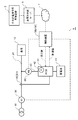
図1は、本発明の実施の形態に係る電力調整システム1のシステム構成を概念的に示す図である。
以下の各図において、本発明の本質に関わらない部分の構成については省略してあり、図示されていない。
(First embodiment)
A power adjustment system, an information processing device, an information processing method, and a program according to the first embodiment of the present invention will be described below.
FIG. 1 is a diagram conceptually showing a system configuration of a
In each of the following drawings, a configuration of a portion not related to the essence of the present invention is omitted and not shown.
電力調整システム1は、蓄電池40と、PCS(Power Conditioner System)42と、制御装置50と、第1スマートメータM1と、を含む。
The
電力系統10と負荷12が、電力ライン20により電気的に接続され、電力系統10から負荷12に電力が供給される。
負荷12は、エアコン、照明機器、冷蔵庫、テレビ、電子レンジ、ドライヤー、パーソナルコンピュータ、ゲーム機、電話機、給湯器、電気自動車、およびプラグインハイブリッド自動車等、様々な電気機器の少なくとも一つであり、特に限定されない。
The
The
図1では、蓄電池40を含むシステムを示しているが、これに限定されず、発電装置(不図示)を含むシステム、あるいは、蓄電池40と発電装置の両方を含むシステムであってもよい。
Although FIG. 1 shows a system including the
電力系統10の周波数(以下、「系統周波数」とも呼ぶ)は、電力系統10内の発電設備(不図示)の出力や需要家負荷の電力消費に応じて変動する。また、電力系統10内には、発電設備と、電力を消費する負荷以外に、電力を充放電する蓄電設備も存在する。近年、一般家庭でも発電装置や蓄電装置が普及しつつあり、電力系統10の電力の需要と供給を一致させ、系統周波数を一定に保つために、様々な規模、様々な形態の多数のエネルギー関連装置(発電装置および蓄電装置)を統合的に制御する必要がある。
The frequency of the power system 10 (hereinafter, also referred to as “system frequency”) changes according to the output of a power generation facility (not shown) in the
系統周波数を基準値に保持する制御を行うための需給調整のための制御信号が、中央給電指令所の管理装置3から送信される。この制御信号に従った、各需要家の蓄電池40や発電装置の統合的な入出力制御により、電力調整システム1は、電力需給調整を行うことができる。
A control signal for supply and demand adjustment for performing control for holding the system frequency at the reference value is transmitted from the management device 3 at the central power feeding command center. By the integrated input/output control of the
各需要家の制御装置50は、中央給電指令所の管理装置3からの制御信号を、蓄電池中給のサーバ5を経由して受信し、蓄電池40の充放電(または発電装置の出力)を制御する。制御信号は、たとえば、LFC(Load Frequency Control)信号を含むが、これに限定されない。
The
PCS42は、電力ライン20を流れる電力の電流値を計測する第1センサS1(系統CTとも呼ぶ)と、PCS42から電力ライン20に入出力する電力の電流値を測定する内部センサS0と、図示されない発電装置から出力される電力の電流値を計測するPV(PhotoVoltaics)センサ(PVCTとも呼ぶ)と、から取得される計測値と、中央給電指令所の管理装置3からの制御信号等に基づいて、蓄電池40の充放電や発電装置の出力を制御する。なお、実際の電力制御は、別途系統電圧値の測定センサがあり、その電圧と上記電流(第1センサS1、内部センサS0、PVCT等)とを用いて、電力値に換算して実施する。以下で校正と説明する場合は、暗に、この電圧センサについても電流センサと、まとめて記載しているものとする。つまり電流センサの校正の話をする場合は、電流センサと関連する、たとえば、PCS42内の電圧センサを含めた電力値の校正を意味する。
The
ここで、PCS42による各需要家の電力制御の精度が低いと、電力系統10の需給バランスに影響を及ぼす可能性がある。上述したように、たとえば、3つのセンサの電流値に基づいて蓄電池40の充放電量がPCS42により制御される。特に、PCS42に使用される内部センサS0は、コストを抑えたものであることが多く、その測定精度が低い可能性がある。また、各センサは、周辺の温度に応じて測定値に誤差が生じることも知られている。さらに、センサの経年劣化による精度低下も考えられる。
Here, if the accuracy of power control of each consumer by the
このように、各センサについて、その校正が定期的に行われるのが望ましい。本発明の実施の形態に係る情報処理装置100は、特に、PCS42の内部センサS0を簡易に定期的に校正する手段を提供する。
In this way, it is desirable that the calibration of each sensor be performed regularly. The
図1の例では、PCS42と制御装置50を分けて記載しているが、これらは物理的または論理的に分かれて構成されてもよいし、物理的または論理的に一体となって構成されてもよい。
In the example of FIG. 1, the
情報処理装置100は、制御装置50およびPCS42のいずれか一方、または、PCS42と制御装置50が一体となった装置により実現されてもよいし、PCS42と制御装置50でそれぞれ情報処理装置100の機能を分担して実現してもよい。
The
本実施形態では、情報処理装置100は、制御装置50により実現される。
In the present embodiment, the
後述するように、情報処理装置100は、内部センサS0を校正する代わりに、内部センサS0の計測値を元に制御されるべき電力ライン20に入出力される電力を示す指示値を補正する補正係数を算出する。
As will be described later, the
制御装置50により情報処理装置100が実現される構成では、電力ライン20に入出力される電力をPCS42に指示する指示値に補正係数を乗じて、制御装置50からPCS42に指示値が送信される。そして、PCS42が受信した補正後の指示値に従い電力を制御することで内部センサS0の校正が実現する。
In the configuration in which the
また、PCS42により情報処理装置100が実現される構成では、PCS42が制御装置50から受信した指示値に補正係数を乗じて電力制御に用いることで内部センサS0の校正が実現する。
In the configuration in which the
図2は、本実施形態の情報処理装置100(各装置:たとえば、制御装置50、PCS42、または、PCS42と制御装置50の一体型装置)を実現するコンピュータ80の構成の一例を示す図である。また、本実施形態の第1スマートメータM1、および第2スマートメータM2も、コンピュータ80により実現される。
なお、本実施形態の第1スマートメータM1は、第2の電力量計に相当し、第2スマートメータM2は、第1の電力量計に相当する。
FIG. 2 is a diagram showing an example of the configuration of a
The first smart meter M1 of the present embodiment corresponds to the second watt hour meter, and the second smart meter M2 corresponds to the first watt hour meter.
本実施形態のコンピュータ80は、CPU(Central Processing Unit)82、メモリ84、メモリ84にロードされた図2の構成要素を実現するプログラム90、そのプログラム90を格納するストレージ85、I/O(Input/Output)86、およびネットワーク接続用インタフェース(通信I/F87)を備える。
The
CPU82、メモリ84、ストレージ85、I/O86、通信I/F87は、バス89を介して互いに接続され、CPU82により情報処理装置100全体が制御される。ただし、CPU82などを互いに接続する方法は、バス接続に限定されない。
The
メモリ84は、RAM(Random Access Memory)やROM(Read Only Memory)などのメモリである。ストレージ85は、ハードディスク、SSD(Solid State Drive)、またはメモリカードなどの記憶装置である。
The
ストレージ85は、RAMやROMなどのメモリであってもよい。ストレージ85は、コンピュータ80の内部に設けられてもよいし、コンピュータ80がアクセス可能であれば、コンピュータ80の外部に設けられ、コンピュータ80と有線または無線で接続されてもよい。あるいは、コンピュータ80に着脱可能に設けられてもよい。
The
CPU82が、ストレージ85に記憶されるプログラム90をメモリ84に読み出して実行することにより、各実施形態の情報処理装置100の各ユニットの各機能を実現することができる。
When the
I/O86は、コンピュータ80と他の装置間のデータおよび制御信号の入出力制御を行う。さらに、I/O86は、他の記録媒体の読み取りまたは書き込み装置(不図示)とのデータの入出力制御を行ってもよい。
The I/
通信I/F87は、コンピュータ80と外部の装置との通信を行うためのネットワーク接続用インタフェースである。通信I/F87は、有線回線と接続するためのネットワークインタフェースでもよいし、無線回線と接続するためのネットワークインタフェースでもよい。たとえば、情報処理装置100(たとえば、制御装置50)を実現するコンピュータ80は、通信I/F87によりネットワーク7を介して蓄電池中給のサーバ5と接続される。あるいは、情報処理装置100(たとえば、制御装置50)実現するコンピュータ80は、通信I/F87により、第1スマートメータM1および第2スマートメータM2と無線通信する。
The communication I/
本発明の各実施形態の情報処理装置100の各構成要素は、図2のコンピュータ80のハードウェアとソフトウェアの任意の組合せによって実現される。そして、その実現方法、装置にはいろいろな変形例があることは、当業者には理解されるところである。以下説明する各実施形態の情報処理装置を示す機能ブロック図は、ハードウェア単位の構成ではなく、論理的な機能単位のブロックを示している。
Each component of the
図1に戻り、制御装置50は、たとえば、EMS(Energy Management System)であり、制御対象となる蓄電池40により、具備する機能やその性能は様々であり、限定されない。
Returning to FIG. 1, the
制御装置50は、上述したように、蓄電池中給のサーバ5とネットワーク7を介して通信を行う機能を有し、サーバ5からの指示に従い、蓄電池40を制御してもよい。制御装置50とサーバ5との間の通信手段と対応プロトコルも様々であり、限定されないが、所定の認証および暗号化処理によりセキュリティが確保された上で接続される。
As described above, the
第1スマートメータM1は、電力会社から需要家に支給される。第1スマートメータM1は電力量計(不図示)と、通信部(不図示)とを含む。第1スマートメータM1は、送配電ネットワークを経由して需要家宅に供給される電力の消費量(または、需要家宅から逆潮流される電力量)を計測する。電力量計により計測された検針データは、通信部により、第1スマートメータM1から電力会社のサーバ(不図示)に、所謂Aルートを経由して無線通信で定期的(たとえば、30分間隔)に送信される。この検針データは、電気料金の計算等に使用される。 The first smart meter M1 is supplied to the consumer from the electric power company. The first smart meter M1 includes a power meter (not shown) and a communication unit (not shown). The first smart meter M1 measures the consumption amount of electric power supplied to the consumer's home via the power transmission/distribution network (or the amount of electric power flowing backward from the consumer's home). The meter reading data measured by the watt-hour meter is periodically (for example, every 30 minutes) by wireless communication from the first smart meter M1 to the server (not shown) of the power company via the so-called A route by the communication unit. Sent to. This meter reading data is used for calculation of electricity charges and the like.
第1スマートメータM1の通信部は、さらに、所謂Bルートを経由して、需要家宅内の通信機器(たとえば、HEMS(Home Energy Management System)や本実施形態の制御装置50等)と通信することができる。
The communication unit of the first smart meter M1 further communicates with a communication device (for example, a HEMS (Home Energy Management System) or the
Bルートの通信方法は、特に限定されないが、たとえば、920MHz帯を使用する特定小電力無線方式、たとえば、Wi−SUN等の通信規格に基づく通信方式、または、Zigbee(登録商標)等のIEEE802.15.4上で動作する無線通信規格の通信方式を利用できる。Bルートは、セキュリティを確保するために、所定の認証手続きを行った上で接続が確立する。 The communication method of the B route is not particularly limited, but, for example, a specific low power wireless system using the 920 MHz band, for example, a communication system based on a communication standard such as Wi-SUN, or IEEE802.80 such as Zigbee®. A communication system of a wireless communication standard operating on 15.4 can be used. In order to secure the security, the route B is subjected to a predetermined authentication procedure before the connection is established.
第1スマートメータM1は、たとえば、制御装置50とBルートで無線通信し、第1スマートメータM1から電力に関する計測値を需要家宅内の通信機器に送信することができる。
The first smart meter M1 can wirelessly communicate with the
第1スマートメータM1から制御装置50に送信される検針データは、限定されないが、たとえば、電力瞬時値、積算電力量の少なくともいずれか一方、ならびに、各値が測定(または算出)された時刻を示す時刻情報を含む。
The meter reading data transmitted from the first smart meter M1 to the
本実施形態の電力調整システム1では、さらに、第2スマートメータM2が、PCS42から電力ライン20に電力が入出力される電力ライン22上に設置される。第2スマートメータM2は、電力量計(不図示)と、通信部(不図示)とを有していればよく、たとえば、スマートメータであってもよいが、これに限定されない。
In the
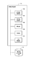
図3は、本発明の実施の形態に係る情報処理装置100の構成を論理的に示す機能ブロック図である。
本実施形態の情報処理装置100は、計測値取得部102と、指示値取得部104と、算出部106と、を備える。
計測値取得部102は、電力系統10と負荷12の間の電力ライン20に流れる電力に関する計測値を取得する。
指示値取得部104は、蓄電池40から電力ライン20に入出力すべき電力を示す指示値を取得する。
FIG. 3 is a functional block diagram logically showing the configuration of the
The
The measurement
The instruction
算出部106は、指示値に従い蓄電池40から入出力される電力が制御されて電力ライン20に入出力されたとき、計測値(PCS42から出力された電力[W]、または、PCS42に入力された電力[W])が、対応する指示値になるように、指示値を補正する補正係数を算出する。
When the electric power input/output to/from the
本明細書において、「取得」とは、自装置が他の装置や記憶媒体に格納されているデータまたは情報を取りに行くこと(能動的な取得)、たとえば、他の装置にリクエストまたは問い合わせして受信すること、他の装置や記憶媒体にアクセスして読み出すこと等、および、自装置に他の装置から出力されるデータまたは情報を入力すること(受動的な取得)、たとえば、配信(または、送信、プッシュ通知等)されるデータまたは情報を受信すること等、の少なくともいずれか一方を含む。また、受信したデータまたは情報の中から選択して取得すること、または、配信されたデータまたは情報を選択して受信することも含む。 In this specification, "acquisition" means that the device itself acquires data or information stored in another device or a storage medium (active acquisition), for example, requests or inquires to another device. Receiving, reading and accessing other devices or storage media, and inputting data or information output from other devices to its own device (passive acquisition), for example, distribution (or , Sending, push notification, etc.) and/or receiving data or information. It also includes selecting and acquiring from the received data or information, or selecting and receiving the distributed data or information.
計測値取得部102が取得する計測値は、以下に例示される。
(1)第2スマートメータM2で計測されるPCS42から電力ライン20に入出力される電力の積算電力量(Wh)
(2)第2スマートメータM2で計測されるPCS42から電力ライン20に入出力される電力の瞬時値(W)
(3)電力ライン20の電力系統10側に流れる電力の電流値(第1センサS1の計測値)
(4)電力ライン20の負荷12側に流れる電力の電流値(図10の第2センサS2の計測値)
(5)第1スマートメータM1で計測される積算電力量(Wh)
(6)第1スマートメータM1で計測される電力瞬時値(W)
The measurement values acquired by the measurement
(1) Accumulated electric energy (Wh) of electric power input/output to/from the
(2) Instantaneous value (W) of electric power input/output to/from the
(3) Current value of electric power flowing to the
(4) Current value of power flowing to the
(5) Integrated electric energy (Wh) measured by the first smart meter M1
(6) Instantaneous power value (W) measured by the first smart meter M1
第2スマートメータM2の計測値は、Bルート経由の無線通信で第2スマートメータM2から制御装置50に送信される。したがって、情報処理装置100がPCS42によって実現される他の実施形態では、第2スマートメータM2の計測値は、制御装置50にBルート経由の無線通信で送信された後、制御装置50からPCS42に有線若しくは無線通信により送信され、計測値取得部102により取得される。
The measurement value of the second smart meter M2 is transmitted from the second smart meter M2 to the
また、後述する実施形態において、第1センサS1または図11の第2センサS2の計測値は、PCS42に入力される。したがって、情報処理装置100が制御装置50によって実現される形態では、PCS42に入力された後、PCS42から制御装置50に有線若しくは無線通信により送信され、計測値取得部102により取得される。
Further, in an embodiment described later, the measurement value of the first sensor S1 or the second sensor S2 of FIG. 11 is input to the
指示値取得部104が取得する指示値は、制御装置50からPCS42に送信される値である。本実施形態では、情報処理装置100は制御装置50によって実現されるので、指示値取得部104は、制御装置50が保持している指示値を取得する。情報処理装置100がPCS42によって実現される形態では、指示値取得部104は、制御装置50から指示値を受信する。
The instruction value acquired by the instruction
また、上述したように、情報処理装置100が制御装置50により実現される本実施形態では、指示値に補正係数が乗算されて補正後の指示値が制御装置50からPCS42に送信される。情報処理装置100がPCS42により実現される形態では、指示値に補正係数を乗算して補正し、補正された指示値に基づいて、PCS42が蓄電池40の充放電を制御することで、電力ライン20に入出力される電力が指示値に等しくなる。
Further, as described above, in the present embodiment in which the
算出部106は、所定期間毎に補正係数を算出する。
なお、計測値取得部102で計測値を取得する時間間隔も所定期間としてよいが、必ずしも同じでなくてもよい。たとえば、計測値取得部102は、30分毎に計測値を取得し、算出部106は60分毎に補正係数を算出してもよい。その場合、算出部106は、計測値取得部102が30分毎に取得した2つの計測値を用いて補正係数を算出する。
The
The time interval at which the measurement
本実施形態では、所定期間は30分とするが、これに限定されない。たとえば、45分、60分等でもよいが、時間経過に応じたPCS42周辺の温度差によって、各センサの計測値に、許容範囲を超える誤差が生じるタイミングで補正係数が見直されるのが望ましい。たとえば、所定期間を朝9時から12時までの3時間とした場合、この間の温度変化が大きく、計測値に許容範囲を超える誤差が生じる可能性があるので、所定期間は30分等として、比較的短いスパンで補正係数を更新した方がよい。
In the present embodiment, the predetermined period is 30 minutes, but is not limited to this. For example, it may be 45 minutes, 60 minutes, or the like, but it is desirable that the correction coefficient be reviewed at a timing when an error exceeding the allowable range occurs in the measurement value of each sensor due to the temperature difference around the
本実施形態において、第2スマートメータM2は、PCS42から電力ライン22に入出力される電力を計測し、Bルートを経由して制御装置50に計測値を送信する。本実施形態では、第2スマートメータM2からPCS42に計測値を送信するタイミングは、PCS42から第2スマートメータM2に対し、計測値を要求した時であるが、これに限定されない。第2スマートメータM2から制御装置50に対し、所定期間毎に計測値を送信する構成としてもよい。
In the present embodiment, the second smart meter M2 measures the electric power input/output from the
計測値取得部102は、計測値として、第2スマートメータM2から所定期間毎の積算電力量を取得する。計測値取得部102が第2スマートメータM2から電力瞬時値を取得する構成については、後述する実施形態で説明する。
The measurement
本実施形態では、第2スマートメータM2と制御装置50の間は、920MHz帯を使用する特定小電力無線方式(以後、920MHz通信と呼ぶ)で無線通信されている。そのため、近辺で他の装置が920MHz通信を行っている間は通信ができなかったり、通信品質は保証されていないため、時間間隔を空けて計測値を読み取り、エラー時にリトライできる余裕があるのが好ましい。
In the present embodiment, wireless communication is performed between the second smart meter M2 and the
第2スマートメータM2から送信される積算電力量は、送信時点での第2スマートメータM2での検針値である。したがって、計測値取得部102は、前回(30分前)の読み込み値と今回の読み込み値の差分(W)を算出し、各値の時刻情報を用いて所定期間(30分間)の積算電力量(Wh)を算出する。
The integrated electric energy transmitted from the second smart meter M2 is a meter reading value of the second smart meter M2 at the time of transmission. Therefore, the measurement
以後、本明細書では、計測値取得部102が取得した検針値から積算電力量を算出する処理については説明を省略し、「積算電力量」を計測値取得部102が取得する計測値として説明する。
Hereinafter, in this specification, the description of the process of calculating the integrated electric energy from the meter reading value acquired by the measured
本実施形態において、算出部106は、積算電力量が、所定値を超えた場合に、所定期間(たとえば、30分間)毎の積算電力量と、対応する指示値を所定期間、積算した積算指示値とが所定の関係を満たす補正係数を算出する。
In the present embodiment, when the integrated power amount exceeds a predetermined value, the
ここで、所定値とは、第2スマートメータM2の計測値の有効桁数の所定倍数(たとえば、100倍)である。
言い換えると、第2スマートメータM2の計測誤差を許容できる範囲の計測値が得られた時に、補正係数の算出に計測値を使用する。たとえば、第2スマートメータM2の有効桁数が10Whの場合、計測値が100Whでは、誤差が約10%含まれる可能性がある。計測値が1000Whでは、誤差は約1%程度となる。本実施形態では、第2スマートメータM2の有効桁数の所定倍数を超える計測値を算出に用いる。
Here, the predetermined value is a predetermined multiple (for example, 100 times) of the number of significant digits of the measurement value of the second smart meter M2.
In other words, when a measurement value within a range in which the measurement error of the second smart meter M2 is acceptable is obtained, the measurement value is used to calculate the correction coefficient. For example, when the number of significant digits of the second smart meter M2 is 10 Wh, when the measured value is 100 Wh, the error may be about 10%. When the measured value is 1000 Wh, the error is about 1%. In this embodiment, a measurement value that exceeds a predetermined multiple of the number of significant digits of the second smart meter M2 is used for calculation.
したがって、要求される精度(誤差の許容範囲等)に合わせて所定値を設定することで、要求水準を満たす電力調整システム1を提供することができる。
Therefore, it is possible to provide the
なお、上述した所定期間が短いと、第2スマートメータM2の計測値の積算電力量の値が第2スマートメータM2の有効桁数の所定倍数(たとえば、100倍)を超えない可能性がある。従って、所定期間は、第2スマートメータM2の計測値が第2スマートメータM2の有効桁数の所定倍数を超える長さに延長するのが好ましい。 If the above-mentioned predetermined period is short, the value of the integrated electric energy of the measurement value of the second smart meter M2 may not exceed a predetermined multiple (for example, 100 times) of the number of significant digits of the second smart meter M2. .. Therefore, it is preferable to extend the predetermined period to a length in which the measured value of the second smart meter M2 exceeds a predetermined multiple of the number of significant digits of the second smart meter M2.
したがって、所定期間を経過後に、積算電力量が所定値を超えていない場合は、さらに、積算を続け、積算電力量が所定値を超えた後に、補正係数を算出する。 Therefore, when the integrated electric energy does not exceed the predetermined value after the elapse of the predetermined period, the integration is further continued, and the correction coefficient is calculated after the integrated electric energy exceeds the predetermined value.
また、少なくとも、1日の温度変化が激しい(単位時間当たりの温度変化が第1閾値以上の)時間帯に計測値の取得が行われるように、計測タイミングが設定されるのが好ましい。計測値取得のタイミングは、予めスケジューリングしてもよいし、温度変化や計測値に応じて、スケジュールを更新してもよい。 In addition, it is preferable that the measurement timing be set such that the measurement value is acquired at least during a time period in which the temperature change is large (the temperature change per unit time is equal to or more than the first threshold value) in one day. The measurement value acquisition timing may be scheduled in advance, or the schedule may be updated according to the temperature change or the measurement value.
たとえば、温度変化が激しい場合は、計測タイミングの間隔を短く設定し、温度変化があまりないような場合(単位時間当たりの温度変化が第2閾値未満(第1閾値>第2閾値))には、計測タイミングの間隔を長く設定し、計測値が所定値未満の場合は、計測タイミングの間隔を長く設定し、計測値が所定値を超える場合は、計測タイミングの間隔を短く設定してもよい。
予め決められた所定期間やスケジュールで取得された計測値が、所定値を超えていない場合は、積算を継続し、所定値を超えた時点以降に補正係数を算出すればよい。
For example, when the temperature change is large, the measurement timing interval is set to be short, and when the temperature change is not so large (the temperature change per unit time is less than the second threshold value (first threshold value>second threshold value)). The measurement timing interval may be set long, and if the measurement value is less than the predetermined value, the measurement timing interval may be set long, and if the measurement value exceeds the predetermined value, the measurement timing interval may be set short. ..
When the measurement value acquired in the predetermined period or schedule determined in advance does not exceed the predetermined value, the integration may be continued and the correction coefficient may be calculated after the time when the predetermined value is exceeded.
また、本実施形態では、制御装置50が一つの指示値xを用いる例について説明するが、他の例では、指示値xは、たとえば、需要家利用の電力を調整するために蓄電池40の充放電を制御する指示値x1と、需給調整用に蓄電池40の充放電を制御する指示値x2等、複数の指示値を含んでもよい。
Further, in the present embodiment, an example in which the
指示値xの積算時間z分の積算指示値C(z)は以下の式(1)で示される。積算時間zは所定期間または積算電力量が積算された時間(たとえば、30分)である。積算電力量の積算時間が所定期間を超えた場合は、zは積算時間(たとえば、所定期間の30分を8分超えた場合、38分)となる。

ここで、内部センサS0の校正前の積算電力量が誤差αを含むとすると、その誤差αを補正する補正係数をAとする。以下の式(2)に示されるように、積算指示値C(z)に算出された補正係数Aを乗じたとき、第2スマートメータM2で計測される計測値D(z)は、指示値に等しくなる。
ここで、補正係数Aは、1/誤差αである。また、誤差αは、補正前の第2スマートメータM2で計測される計測値D(z)を積算指示値C(z)で除した値で示される。したがって、補正係数Aは、1/誤差αであるので、積算指示値C(z)を補正前の第2スマートメータM2で計測される計測値D(z)で除した値となる。
補正係数の算出方法は、これに限定されず、算出部106は、積算電力量(計測値)D(z)と、積算指示値C(z)とが所定の関係を満たす補正係数Aを求めてもよい。
Here, the correction coefficient A is 1/error α. The error α is indicated by a value obtained by dividing the measurement value D(z) measured by the second smart meter M2 before correction by the integration instruction value C(z). Therefore, since the correction coefficient A is 1/error α, it is a value obtained by dividing the integration instruction value C(z) by the measurement value D(z) measured by the second smart meter M2 before correction.
The calculation method of the correction coefficient is not limited to this, and the
所定の関係とは、上記例の他に、計測値の有効桁数未満を切り捨てた値や切り上げた値や四捨五入した値と積算指示値C(z)に補正係数Aを乗じたとき、第2スマートメータM2で計測される計測値D(z)が等しくなる例も含む。 In addition to the above example, the predetermined relationship is a value obtained by rounding down a value less than the number of significant digits of the measured value, a value rounded up or a value rounded off, and the integrated instruction value C(z) multiplied by the correction coefficient A. An example in which the measured values D(z) measured by the smart meter M2 are equal is also included.
以下、本発明の実施の形態に係るコンピュータプログラムについて説明する。 Hereinafter, the computer program according to the embodiment of the present invention will be described.
本実施形態のコンピュータプログラム90は、情報処理装置100を実現させるためのコンピュータ80に、電力系統10と負荷12の間の電力ライン20に流れる電力に関する計測値を取得する手順、蓄電池40から電力ライン20に入出力すべき電力を示す指示値を取得する手順、指示値に従い蓄電池40から入出力される電力が制御されて電力ライン20に入出力されたとき、計測値が、対応する指示値になるように、指示値を補正する補正係数を算出する手順、を実行させるように記述されており、計測値を取得する手順において、第2スマートメータM2から所定期間(30分間)の積算電力量(Wh)を取得し、算出する手順において、積算電力量が、所定値を超えた場合に、所定期間(たとえば、30分間)毎の積算電力量と、対応する指示値を所定期間毎に積算した積算指示値とが所定の関係を満たす補正係数を算出するように記述されている。
The
本実施形態のコンピュータプログラム90は、コンピュータ80で読み取り可能な記録媒体に記録されてもよい。記録媒体は特に限定されず、様々な形態のものが考えられる。また、プログラム90は、記録媒体からコンピュータ80のメモリ84にロードされてもよいし、ネットワークを通じてコンピュータ80にダウンロードされ、メモリ84にロードされてもよい。
The
コンピュータプログラム90を記録する記録媒体は、非一時的な有形のコンピュータ80が使用可能な媒体を含み、その媒体に、コンピュータ80が読み取り可能なプログラムコードが埋め込まれる。コンピュータプログラム90が、コンピュータ80上で実行されたとき、コンピュータ80に、情報処理装置100を実現する以下の情報処理方法を実行させる。
The recording medium for recording the
このように構成された本実施形態の情報処理装置100の情報処理方法について、以下説明する。
図4は、本実施形態の情報処理装置100の動作の一例を示すフローチャートである。
本発明の実施の形態に係る情報処理方法は、情報処理装置100の情報処理方法であり、情報処理装置100を実現するコンピュータ80により実行される情報処理方法である。
本実施形態の情報処理方法は、情報処理装置100が、電力系統10と負荷12の間の電力ライン20に流れる電力に関する計測値を取得し(ステップS101、ステップS107)、蓄電池40から電力ライン20に入出力すべき電力を示す指示値を取得し(ステップS103)、指示値に従い蓄電池40から入出力される電力が制御されて電力ライン20に入出力されたとき、計測値が、対応する指示値になるように、指示値を補正する補正係数を算出し(ステップS113)、さらに、ステップS101およびステップS107において、第2スマートメータM2から所定期間(30分間)の積算電力量(Wh)を取得し、算出する際に、積算電力量が、所定値を超えた場合に(ステップS109のYES)、所定期間(たとえば、30分間)毎の積算電力量と、対応する指示値を所定期間毎に積算した積算指示値とが所定の関係を満たす補正係数を算出する(ステップS111、ステップS113)、ことを含む。
An information processing method of the
FIG. 4 is a flowchart showing an example of the operation of the
The information processing method according to the embodiment of the present invention is an information processing method of the
In the information processing method according to the present embodiment, the
以下、詳細に説明する。
本フローチャートは、情報処理装置100が起動した時に開始し、その後、繰り返し実行される。
まず、計測値取得部102が、第2スマートメータM2から積算電力量を所定期間毎に取得する(ステップS101)。取得した積算電力量は、時刻情報とともに図5(a)の記憶装置110の計測値記憶部112に記憶される。
The details will be described below.
This flowchart is started when the
First, the measurement
次に、指示値取得部104が、指示値xを取得する(ステップS103)。この指示値xは、制御装置50の機能として、蓄電池中給のサーバ5から受信する各種の制御信号と、需要家の負荷12の消費電力量、蓄電池40の充電量、およびPV(不図示)の出力、系統CT、PVCT、内部センサS0等の計測値等に応じて決定される。
Next, the instruction
指示値xは、図6(a)の記憶装置110の指示値記憶部116に時刻情報に関連付けられて記憶される。この例では、1分毎の指示値を記憶しているが、これに限定されない。 The instruction value x is stored in the instruction value storage unit 116 of the storage device 110 of FIG. 6A in association with the time information. In this example, the instruction value for each minute is stored, but the present invention is not limited to this.
そして、開始後、または前回の補正係数算出(ステップS115)後から、30分間経過するまで(ステップS105のNO)、指示値取得部104は、指示値xの取得を繰り返す。たとえば、指示値xは1分毎等に取得して指示値記憶部116に記憶してもよい。
Then, after the start or after the previous correction coefficient calculation (step S115), until the lapse of 30 minutes (NO in step S105), the instruction
あるいは、指示値xが所定値以上の変化があった時に、指示値記憶部116に記憶してもよい。積算指示値は、指示値xと時刻情報に基づいて、積算時間分の指示値に換算すればよい。たとえば、12時の指示値xaと、12時10分の指示値xbが記憶されており、12時から12時32分が積算時間であった場合、積算指示値は、(xa×10/60+xb×22/60)×60とすることができる。 Alternatively, it may be stored in the instruction value storage unit 116 when the instruction value x changes by a predetermined value or more. The accumulated instruction value may be converted into an instruction value for the accumulated time based on the instruction value x and the time information. For example, if the instruction value xa at 12:00 and the instruction value xb at 12:10 are stored and the integration time is from 12:00 to 12:32, the integration instruction value is (xa×10/60+xb X22/60) x60.
そして、30分間経過後に(ステップS105のYES)、計測値取得部102は、第2スマートメータM2から積算電力量(kWh)を受信する(ステップS107)。そして、算出部106は、積算電力量(kWh)の前回と今回の計測値と、それらの時刻情報に基づいて、30分間の積算電力量(Wh)を算出し、時刻情報(今回の計測値の時刻)に関連付けて、図5(b)の記憶装置110の電力積算値記憶部114に記憶する。
Then, after 30 minutes have passed (YES in step S105), the measurement
具体的には、計測値取得部102が、12時30分の計測値(検針値)から12時の計測値(検針値)を減算し、時刻情報から計測時間間隔を算出し、30分間当たりの積算電力量(Wh)に換算する。
Specifically, the measurement
そして、算出部106が、算出された積算電力量が所定値を超えるか否かを判定する(ステップS109)。算出部106は、積算電力量が、所定値を超えた場合に(ステップS109のYES)、積算時間分の指示値を積算して積算指示値を算出し、時刻情報に関連付けて、図6(b)の記憶装置110の積算指示値記憶部118に記憶する(ステップS111)。
Then, the
一方、ステップS109で、積算電力量が、所定値を超えない場合(ステップS109のNO)、ステップS103に戻り、指示値取得部104が指示値を取得する(ステップS103)。ステップS109から戻った場合には、既に成功の補正係数の算出時から30分間は経過しているので(ステップS105のYES)、算出部106が第2スマートメータM2から計測値を取得する。
On the other hand, if the integrated electric energy does not exceed the predetermined value in step S109 (NO in step S109), the process returns to step S103, and the instruction
ここでは、先程、所定値を超えなかった積算電力量がさらに積算されていく。ステップS109では、前回補正係数を算出した時の計測値と、今回取得した計測値から、その間の積算電力量を算出する。そして、積算電力量が所定値を超えるまで、積算を続ける。 Here, the integrated electric energy that did not exceed the predetermined value is further integrated. In step S109, the integrated electric energy in the meantime is calculated from the measured value obtained when the correction coefficient was calculated last time and the measured value acquired this time. Then, the integration is continued until the integrated electric energy exceeds a predetermined value.
そして、ステップS109で、積算電力量が所定値を超えた場合(ステップS109のYES)、上述したようにステップS111で積算指示値が算出される。このとき、所定期間を超えて計測値が積算された場合、時刻情報から積算時間を算出し、積算時間分の指示値を積算し、積算指示値を算出する。 Then, if the integrated electric energy exceeds the predetermined value in step S109 (YES in step S109), the integrated instruction value is calculated in step S111 as described above. At this time, when the measured values are accumulated over a predetermined period, the accumulated time is calculated from the time information, the instruction value for the accumulated time is accumulated, and the accumulated instruction value is calculated.
このようにして算出された積算電力量と積算指示値を用いて、算出部106は、補正係数Aを用いて指示値を補正した場合に、積算電力量が、積算指示値となるように、補正係数Aを算出する(ステップS113)。具体的には、積算指示値を積算電力量で除して補正係数Aを算出する。そして、算出部106は、算出された補正係数Aを指示値xに乗算して指示値xを補正し、補正した指示値xをPCS42に送信する(ステップS115)。そして、ステップS101に戻り、本処理を繰り返す。
Using the thus calculated integrated electric energy and integrated instruction value, the
図示してないが、PCS42では、指示値xを制御装置50から受信し、受信した指示値xを用いて電力ライン20に入出力する電力を制御する。これにより、内部センサS0の誤差が校正され、指示値xに一致した電力が電力ライン20に入出力されることになる。
Although not shown, the
なお、本実施形態のフローチャートは一例であり、各ステップの手順の順序は上記フローに限定されない。ステップS101の計測値の取得手順と、ステップS103の指示値取得手順は、必ずしも一連の手順で行われなくてもよい。それぞれ独立して、または並列に実行されてもよい。
また、ステップS111、ステップS113、およびステップS115の手順も、必ずしも一連の手順で行われなくてもよい。それぞれ独立して実行されてもよい。
The flowchart of this embodiment is an example, and the order of the procedure of each step is not limited to the above flow. The measurement value acquisition procedure of step S101 and the instruction value acquisition procedure of step S103 do not necessarily have to be performed in a series of procedures. Each may be executed independently or in parallel.
Moreover, the procedure of step S111, step S113, and step S115 does not necessarily have to be performed in a series of procedures. Each may be executed independently.
以上説明したように、電力調整システム1の情報処理装置100において、計測値取得部102により取得される計測値が、指示値取得部104により取得される対応する指示値になるように、算出部106により補正係数Aが算出される。
As described above, in the
本実施形態では、計測値は、積算電力量であり、所定期間毎に取得された積算電力量を用いて補正係数を算出する。所定期間は、温度変化による計測値の誤差が許容範囲を超えないように定められ、かつ、積算電力量が、計測値の有効桁数を超える値となるように設定される。 In the present embodiment, the measured value is the integrated power amount, and the correction coefficient is calculated using the integrated power amount acquired every predetermined period. The predetermined period is set so that the error of the measured value due to the temperature change does not exceed the allowable range, and the integrated electric energy is set to a value exceeding the number of significant digits of the measured value.
この構成によれば、内部センサS0の校正を行う際、基準となる計測値の有効桁数を考慮して補正することができるので、その精度が向上する。また、要求される精度に合わせて積算電力量の所定値を設定することで、要求水準を満たす電力調整システム1を提供することができる。
このように、本実施形態の電力調整システム1および情報処理装置100によれば、需要家において高精度な電力制御を実現することができる。
According to this configuration, when the internal sensor S0 is calibrated, it can be corrected in consideration of the effective number of digits of the reference measurement value, so that the accuracy is improved. Further, by setting the predetermined value of the integrated electric energy according to the required accuracy, it is possible to provide the electric
As described above, according to the
(第2の実施の形態)
次に、本発明の第2の実施の形態について、以下説明する。
本実施形態の電力調整システム1および情報処理装置100は、上記実施形態と同様な構成を有するので、図1および図3を用いて説明する。
本実施形態の情報処理装置100は、上記実施形態とは、第2スマートメータM2から計測値として電力瞬時値を取得し、電力瞬時値を用いて補正係数を算出する点で相違する。
(Second embodiment)
Next, a second embodiment of the present invention will be described below.
The
The
上記実施形態では、少なくとも積算電力量が所定値(有効桁数の所定倍数)を超えるまで、補正係数の算出を待つ必要があった。そのため、電力消費量が少ない場合に、補正係数の算出タイミングの間隔が長くなってしまう可能性があった。補正係数の算出間隔が長いと、その間に大きな温度変化が起きる可能性が高くなり、温度変化によって内部センサS0に誤差が生じてしまう可能性がある。
そこで、本実施形態では、瞬時値を用いることで、補正係数の算出タイミングを任意の時刻に設定することを可能にする。
In the above-described embodiment, it is necessary to wait for the calculation of the correction coefficient at least until the integrated electric energy exceeds a predetermined value (a predetermined multiple of the number of significant digits). Therefore, when the power consumption is small, the interval between the correction coefficient calculation timings may become long. If the correction coefficient calculation interval is long, there is a high possibility that a large temperature change will occur during that interval, and an error may occur in the internal sensor S0 due to the temperature change.
Therefore, in this embodiment, it is possible to set the correction coefficient calculation timing to an arbitrary time by using the instantaneous value.
本実施形態において、計測値取得部102は、第2スマートメータM2から、電力ライン22に入出力される電力の電力瞬時値を計測値として少なくとも1つ取得する。
指示値取得部104は、計測値取得部102が少なくとも1つの電力瞬時値を取得した時の少なくとも1つの指示値をそれぞれ取得する。
算出部106は、第2スマートメータM2から取得した少なくとも1つの電力瞬時値、および電力瞬時値に対応する指示値を用いて補正係数Aを算出する。
In the present embodiment, the measurement
The instruction
The
算出部106は、複数の電力瞬時値の平均値、および複数の指示値の平均値をそれぞれ算出する。そして、算出部106は、当該算出された電力瞬時値の平均値と、対応する指示値の平均値とが所定の関係を満たす補正係数を算出する。または、算出部106は、第2スマートメータM2から取得した複数の電力瞬時値の積算値を算出してもよい。そして、算出部106は、当該算出された電力瞬時値の積算値と、対応する指示値の積算値とが所定の関係を満たす補正係数を算出してもよい。
The
具体的には、算出部106は、指示値の平均値を電力瞬時値の平均値で除して補正係数Aを算出する。あるいは、算出部106は、指示値の積算値を電力瞬時値の積算値で除して補正係数Aを算出する。あるいは、算出部106は、少なくとも1つの指示値を少なくとも1つの電力瞬時値で除して補正係数Aを算出してもよい。
Specifically, the
以下、より詳細に説明する。
計測値取得部102が、電力ライン20から電力瞬時値を取得するタイミングは、たとえば、所定期間の所定時間内で、連続したタイミング(たとえば、30分間の初めの1分間で数秒おきに10回等)であるのが好ましい。
The details will be described below.
The timing at which the measurement
指示値取得部104が、指示値を取得するタイミングは、計測値取得部102が計測値を取得したのと同じタイミングであるのが望ましい。ただし、必ずしも同時でなくてもよい。
It is desirable that the instruction
算出される平均値は、平均値、中央値等、複数の値を統計処理した値を含む。また、計測値取得部102が取得した計測値が0の場合、その計測値は演算から除外する。また、計測値取得部102が取得した計測値と対応する指示値との差が、指示値に対して所定割合以上の場合、その計測値は演算から除外する。また、計測値が0であるときは、計測値の誤差を考慮して、計測値の有効桁数より小さい値は0であるとしてよい。
The calculated average value includes a value obtained by statistically processing a plurality of values such as an average value and a median value. If the measured value acquired by the measured
計測値が除外された場合、所定個数または所定積算出力値以上の計測値が取得されるまで、計測値取得部102は計測値を取得してもよい。このとき、たとえば、初めの有効な計測値が取得されてから所定時間(たとえば、3分以上)経過しても有効な計測値が所定個数取得できない場合、時間間隔を空けてから、再度、処理を開始してもよい。
When the measured value is excluded, the measured
また、平均値を算出する計測値の個数は、計測値に応じて変更できてもよい。計測値の変動が少なく、ほぼ一定で、その標準偏差が第1所定値(第1所定割合)未満の場合、個数を少なくし(たとえば、3個)、また、取得タイミングの間隔を長く(たとえば、10秒毎)してもよい。 Further, the number of measurement values for calculating the average value may be changed according to the measurement values. When the fluctuation of the measurement value is small and almost constant, and the standard deviation thereof is less than the first predetermined value (first predetermined ratio), the number of the measurement values is reduced (for example, 3), and the interval of the acquisition timing is increased (for example, the time). Every 10 seconds).
一方、計測値の変動が大きく、その標準偏差が第2所定値(第2所定割合)以上の場合(ここで、第2所定値(第2所定割合)>第1所定値(第1所定割合))、個数を多くし(たとえば、20個)、また、取得タイミングの間隔を短く(たとえば、1秒毎)してもよい。 On the other hand, when the fluctuation of the measured value is large and the standard deviation thereof is equal to or larger than the second predetermined value (second predetermined ratio) (where, the second predetermined value (second predetermined ratio)>the first predetermined value (first predetermined ratio). )), the number may be increased (for example, 20), and the acquisition timing interval may be shortened (for example, every 1 second).
算出部106は、下記の各式を用いて指示値xの平均値E、第2スマートメータM2の計測値yの平均値F、および補正係数Aを算出する。
ここで、上記式(5)では、指示値xの平均値Eを第2スマートメータM2の計測値yの平均値Fで除して補正係数Aを算出する。
補正係数の算出方法は、これに限定されず、算出部106は、第2スマートメータM2の計測値yの平均値Fと、指示値xの平均値Eとが所定の関係を満たす補正係数Aを求めてもよい。
Here, in the above formula (5), the correction coefficient A is calculated by dividing the average value E of the instruction value x by the average value F of the measurement value y of the second smart meter M2.
The calculation method of the correction coefficient is not limited to this, and the
所定の関係とは、上記例の他に、計測値の有効桁数未満を切り捨てた値や切り上げた値や四捨五入した値と指示値xの平均値Eに補正係数Aを乗じた値を等しくする例も含む。また、積算値を用いる場合は、式(3)と式(4)の右辺のnを除いた式を用いる。また、平均値を用いる場合、第2スマートメータM2の誤差を考慮し、平均値の値が所定の値以上となるまで、計測回数を増やしてもよい。 In addition to the above example, the predetermined relationship is equal to a value obtained by rounding down a value less than the significant digit of the measurement value, a value rounded up or a value rounded off, and a value obtained by multiplying the average value E of the instruction value x by the correction coefficient A. Including examples. Further, when using the integrated value, an expression excluding n on the right side of Expressions (3) and (4) is used. When using the average value, the number of measurements may be increased in consideration of the error of the second smart meter M2 until the value of the average value becomes a predetermined value or more.
以下、本発明の実施の形態に係るコンピュータプログラムについて説明する。
本実施の形態の情報処理装置100は、コンピュータプログラムに対応する各種の処理動作をコンピュータ80のCPU82が実行することにより、前述のような各種ユニットが各種機能として実現される。
Hereinafter, the computer program according to the embodiment of the present invention will be described.
In the
本実施形態のコンピュータプログラムは、情報処理装置100を実現させるためのコンピュータに、電力系統10と負荷12の間の電力ライン20に流れる電力に関する計測値を取得する手順、蓄電池40から電力ライン20に入出力すべき電力を示す指示値を取得する手順、指示値に従い蓄電池40から入出力される電力が制御されて電力ライン20に入出力されたとき、計測値が、対応する指示値になるように、指示値を補正する補正係数を算出する手順、を実行させるように記述されており、計測値を取得する手順において、電力ライン22に入出力される電力の電力瞬時値を計測する第2スマートメータM2から計測値として少なくとも一つの電力瞬時値を取得し、指示値を取得する手順において、少なくとも一つの電力瞬時値を取得した時の少なくとも一つの指示値を取得し、算出する手順において、第2スマートメータM2から取得した少なくとも一つの電力瞬時値、当該電力瞬時値に対応する指示値を用いて補正係数を算出するように記述されている。
The computer program of the present embodiment causes a computer for realizing the
さらに、本実施形態のコンピュータプログラムは、コンピュータに、算出する手順において、第2スマートメータM2から取得した複数の電力瞬時値の平均値と、複数の指示値の平均値とが所定の関係を満たす補正係数を求める手順を実行させるように記述されている。 Further, in the computer program of the present embodiment, in the calculation procedure, the average value of the plurality of electric power instantaneous values acquired from the second smart meter M2 and the average value of the plurality of instruction values satisfy a predetermined relationship. It is described to execute the procedure for obtaining the correction coefficient.
コンピュータプログラム90を記録する記録媒体は、非一時的な有形のコンピュータ80が使用可能な媒体を含み、その媒体に、コンピュータ80が読み取り可能なプログラムコードが埋め込まれる。コンピュータプログラム90が、コンピュータ80上で実行されたとき、コンピュータ80に、情報処理装置100を実現する以下の情報処理方法を実行させる。
The recording medium for recording the
このように構成された本実施形態の情報処理装置100の情報処理方法について、以下説明する。
図8は、本実施形態の情報処理装置100の動作の一例を示すフローチャートである。
本発明の実施の形態に係る情報処理方法は、情報処理装置100の情報処理方法であり、情報処理装置100を実現するコンピュータ80により実行される情報処理方法である。
本実施形態の情報処理方法は、情報処理装置100が、電力系統10と負荷12の間の電力ライン20に流れる電力に関する計測値を取得し(ステップS203)、蓄電池40から電力ライン20に入出力すべき電力を示す指示値を取得し(ステップS207)、指示値に従い蓄電池40から入出力される電力が制御されて電力ライン20に入出力されたとき、計測値が、対応する指示値になるように、指示値を補正する補正係数を算出し(ステップS217)、さらに、ステップS203において、電力ライン22に入出力される電力の電力瞬時値を計測する第2スマートメータM2から計測値として少なくとも一つの電力瞬時値を取得し、ステップS207において、少なくとも一つの電力瞬時値を取得した時の少なくとも一つの指示値をそれぞれ取得し、ステップS217において、第2スマートメータM2から取得した少なくとも一つの電力瞬時値、当該電力瞬時値に対応する指示値を用いて補正係数を算出する(ステップS217)、ことを含む。
An information processing method of the
FIG. 8 is a flowchart showing an example of the operation of the
The information processing method according to the embodiment of the present invention is an information processing method of the
In the information processing method according to the present embodiment, the
さらに、本実施形態の情報処理方法は、情報処理装置100が、第2スマートメータM2から取得した複数の電力瞬時値の平均値と、複数の指示値の平均値とが所定の関係を満たす補正係数を求めることを含む。
Further, in the information processing method of the present embodiment, the
以下、詳細に説明する。
本フローチャートは、情報処理装置100が起動した時に開始し、その後、たとえば、所定期間(30分間等)毎に繰り返し実行される。ここでは、複数の電力瞬時値の平均値を用いて補正係数を算出する例について説明する。
まず、計測値取得部102がカウンタiを1にセットする(ステップS201)。このカウンタiは、第2スマートメータM2から取得し、平均値を算出するデータの有効な個数を示し、平均値を算出するのに必要となる所定数n(たとえば、10)になるまでインクリメントされる。(ここで、iとnは1以上の自然数である。)
The details will be described below.
This flowchart is started when the
First, the measurement
計測値取得部102が、第2スマートメータM2から電力瞬時値を受信する(ステップS203)。受信に成功した電力瞬時値は(ステップS205のYES)、時刻情報に関連付けられて図9(a)の記憶装置110の電力瞬時値記憶部122に記憶される。そして、指示値取得部104が指示値xを取得し、対応する計測値に関連付けて図9(a)の電力瞬時値記憶部122に記憶する。そして、カウンタiがインクリメントされ(ステップS209)、データ数が所定数nを超えたか否かを判定する(ステップS211)。
The measurement
ステップS205で、受信に失敗した場合(ステップS205のNO)、ステップS203に戻り、計測値取得部102が再度、計測値を取得する。また、ステップS205において、有効な計測値であるか否かの判定も行うことができる。たとえば、計測値が0でないこと、さらに、計測値と指示値の差が所定割合未満であるか否かを判定し、全ての条件を満たした場合、ステップS207に進んでもよい。1つでも条件を満たさない場合は、ステップS203に戻る。また、計測値が0でないことの判定においては、計測値の誤差を考慮して、計測値の有効桁数より小さい値は0であると判定してよい。
If the reception fails in step S205 (NO in step S205), the process returns to step S203, and the measurement
そして、データ数(カウンタi)が所定数nを超えるまで、カウンタiがn以下の場合(ステップS211のNO)、ステップS203に戻り、計測値と指示値を収集し、電力瞬時値記憶部122に記憶する。 Then, until the number of data (counter i) exceeds the predetermined number n, if the counter i is n or less (NO in step S211), the process returns to step S203, the measured value and the instruction value are collected, and the instantaneous power value storage unit 122 is used. Remember.
データ数(カウンタi)が所定数nを超えた時(ステップS211のYES)、算出部106が、式(4)を用いて複数の電力瞬時値の平均値Fを算出し、時刻情報に関連付けて図9(b)の記憶装置110の平均値記憶部124に記憶する(ステップS213)。さらに、算出部106が、式(4)を用いて電力瞬時値に対応する複数の指示値の平均値Eを算出し、時刻情報と電力瞬時値の平均値Fに関連付けて指示値の平均値Eを平均値記憶部124に記憶する(ステップS215)。
When the number of data (counter i) exceeds the predetermined number n (YES in step S211), the
算出部106は、平均値記憶部124を参照し、電力瞬時値の平均値Fが、指示値の平均値Eとなるように、式(5)を用いて、補正係数Aを算出する(ステップS217)。算出された補正係数Aは、時刻情報に関連付けられて図10の記憶装置110の補正係数記憶部126に記憶される。
The
そして、算出部106は、算出された補正係数Aを指示値xに乗算して指示値xを補正し、補正した指示値xをPCS42に送信する(ステップS219)。そして、ステップS201に戻り、所定期間毎(たとえば、30分毎)に本処理を繰り返す。
Then, the
図示してないが、PCS42では、指示値xを制御装置50から受信し、受信した指示値xを用いて電力ライン20に入出力する電力を制御する。これにより、内部センサS0の誤差が校正され、指示値xに一致した電力が電力ライン20に入出力されることになる。
Although not shown, the
以上説明したように、電力調整システム1の情報処理装置100において、計測値取得部102により取得される計測値が、指示値取得部104により取得される対応する指示値になるように、算出部106により補正係数Aが算出される。
As described above, in the
本実施形態では、計測値は、電力瞬時値であり、所定期間の所定時間内で、連続したタイミングで取得された計測値の平均値として補正係数の算出処理を行う。
第2スマートメータM2からの計測値の取得は無線通信によるので、通信エラー等により計測値が取得できない可能性がある。本実施形態によれば、複数の計測値を取得し、平均値を用いる構成とすることで、通信エラーによるデータの欠落にも短期間で対応できることとなる。
In the present embodiment, the measurement value is an electric power instantaneous value, and the correction coefficient calculation process is performed as an average value of the measurement values acquired at consecutive timings within a predetermined time of a predetermined period.
Since the measurement value is acquired from the second smart meter M2 by wireless communication, there is a possibility that the measurement value cannot be acquired due to a communication error or the like. According to the present embodiment, a plurality of measurement values are acquired and the average value is used, so that data loss due to a communication error can be dealt with in a short period of time.
また、計測値として積算電力量を用いる上記実施形態では、電力消費量が少ない場合に、補正係数の算出タイミングの間隔が長くなってしまう可能性があった。そして、補正係数の算出間隔が長いと、その間に大きな温度変化が起きる可能性が高くなり、温度変化によって内部センサS0に誤差が生じてしまう可能性がある。本実施形態によれば、補正係数の算出タイミングを任意の時刻に設定することができる。 Further, in the above-described embodiment in which the integrated electric energy is used as the measurement value, there is a possibility that the interval between the correction coefficient calculation timings becomes long when the power consumption is small. If the correction coefficient calculation interval is long, there is a high possibility that a large temperature change will occur during that interval, and an error may occur in the internal sensor S0 due to the temperature change. According to the present embodiment, the correction coefficient calculation timing can be set to an arbitrary time.
このように、本実施形態によれば、上記実施形態と同様な効果を奏するとともに、さらに、効率よく需要家における高精度な電力制御を実現することができる。 As described above, according to the present embodiment, it is possible to achieve the same effect as that of the above-described embodiment, and further, it is possible to efficiently realize highly accurate power control in the consumer.
(第3の実施の形態)
次に、本発明の第3の実施の形態について、以下説明する。
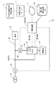
図11は、本発明の実施の形態に係る電力調整システム1のシステム構成を概念的に示す図である。
本実施形態の電力調整システム1は、上記実施形態とは、計測値取得手段として、第2スマートメータM2の換わりに第1センサS1および第2センサS2を有している点で相違する。
(Third Embodiment)
Next, a third embodiment of the present invention will be described below.
FIG. 11: is a figure which shows notionally the system configuration of the
The
本実施形態では、電力ライン20は、電力系統10とPCS42の間の第1電力ライン20aとPCS42と負荷12の間の第2電力ライン20bを含む。
PCS42は、電力ライン20と、蓄電池40または発電装置との間に電気的に接続される。PCS42は、指示値に従い制御した電力を電力ライン20に入出力する。
PCS42は、指示値が負の値に設定されたとき、蓄電池40を放電制御し、指示値が正の値に設定されたとき、蓄電池40を充電制御する。
In the present embodiment, the
The
The
第1センサS1および第2センサS2は、クランプ式電流センサ(CT:Current Transformer)である。第1センサS1は、第1電力ライン20aに流れる電力の電流値を計測する。第2センサS2は、第2電力ライン20bに流れる電力の電流値を計測する。
PCS42は、第1センサS1と、第2センサS2に電気的に接続され、各センサから電流値を取得する。
The first sensor S1 and the second sensor S2 are clamp type current sensors (CT: Current Transformer). The first sensor S1 measures the current value of the power flowing through the
The
本実施形態の情報処理装置100は、上記実施形態と同様な構成を有するので、図3を用いて説明する。
本実施形態の情報処理装置100は、上記実施形態とは、計測値取得手段として計測値取得部102が第1スマートメータM1と、第1センサS1と、第2センサS2とから取得した計測値に基づいて、算出部106が補正係数を算出する構成を有する点で相違する。
The
The
本実施形態の情報処理装置100において、計測値取得部102は、第1センサS1から、第1電力ライン20aを流れる電力の電流値を計測値として少なくとも一つ取得し、さらに、図示されない電圧計により計測される電圧値を用いて第1電力ライン20aを流れる電力の電力瞬時値を算出する。
また、計測値取得部102は、第2センサS2から、第2電力ライン20bを流れる電力の電流値を計測値として少なくとも一つ取得し、さらに、図示されないPCS42内の電圧計により計測される電圧値を用いて第2電力ライン20bを流れる電力の電力瞬時値を算出する。
In the
Further, the measurement
各電力瞬時値は、上記実施形態と同様に、所定期間の所定時間内で、連続したタイミング(たとえば、30分間の初めの1分間で数秒おきに10回等)で計測値取得部102により取得される。
このようにして、計測値取得部102は、第1センサS1、および第2センサS2から、第1センサS1と第2センサS2の各々について少なくとも1つの電力瞬時値を計測値として取得する。
Each power instantaneous value is acquired by the measurement
In this way, the measurement
以後、本明細書では、計測値取得部102が第1センサS1または第2センサS2から取得した電流値と、図示されない電圧計から取得された電圧値に基づいて、電力指示値を算出する処理については説明を省略し、「電力瞬時値」を計測値取得部102が第1センサS1または第2センサS2から取得する計測値として説明する。
Hereinafter, in the present specification, the process of calculating the power instruction value based on the current value acquired by the measurement
さらに、指示値取得部104は、第1センサS1および第2センサS2の少なくとも1つの計測値を取得した時の少なくとも1つの指示値を取得する。指示値取得部104が、指示値を取得するタイミングは、計測値取得部102が計測値を取得したのと同じタイミングであるのが望ましい。ただし、必ずしも同時でなくてもよい。
Furthermore, the instruction
算出部106は、第1センサS1および第2センサS2各々について少なくとも1つの電力瞬時値と、当該計測値に対応する指示値とを用いて補正係数を算出する。
本実施形態では、複数の電力瞬時値の平均値と対応する複数の指示値の平均値を用いて補正係数を算出する例について説明する。さらに、1つの電力瞬時値と対応する一つの指示値を用いて補正係数を算出してもよいと、あるいは、複数の電力瞬時値の積算値と対応する複数の指示値の積算値を用いて補正係数を算出してもよい。
The
In the present embodiment, an example will be described in which the correction coefficient is calculated using the average value of the plurality of instruction values corresponding to the average value of the plurality of power instantaneous values. Further, the correction coefficient may be calculated using one instruction value corresponding to one electric power instantaneous value, or using the integrated value of a plurality of indicated values corresponding to the integrated value of a plurality of instantaneous electric power values. The correction coefficient may be calculated.
算出部106は、第1センサS1および第2センサS2の複数の電力瞬時値の平均値G1、G2と、複数の計測値に対応する複数の指示値xの平均値Eをそれぞれ算出する。
たとえば、蓄電池40の充放電制御において、蓄電池40の放電制御時には、指示値xは負の値となり、蓄電池40の充電制御時には、指示値xは正の値となる。
The calculating
For example, in charge/discharge control of the
電力調整システム1において、電力系統10への逆潮流がないとすると、蓄電池40の放電制御時には、第2センサS2の計測値(電力瞬時値)が、第1センサS1の計測値(電力瞬時値)と内部センサS0で計測される電力瞬時値(負)の合計と等しくなる。また、蓄電池40の充電制御時には、第1センサS1の計測値(電力瞬時値)が、第2センサS2の計測値(電力瞬時値)と内部センサS0で計測される電力瞬時値(正)の合計と等しくなる。
In the
また、内部センサS0の誤差により、内部センサS0の値により電力ライン22に入出力制御される電力が指示値xと異なる場合に、指示値xに補正係数Aを乗じてPCS42に与えることで、PCS42から電力ライン22に入出力される電力を指示値xに等しくすることができる。
Further, when the electric power input/output controlled to the
これらから、算出部106は、以下の式(6)に示すように、算出された第2センサS2の平均値G2から第1センサS1の平均値G1を減算した値が、指示値xの平均値Eとなるように、補正係数Aを算出する。
A=E/(G2−G1) ・・・式(6)
From these, the
A=E/(G2-G1)... Formula (6)
上記式(6)では、指示値の平均値EをG2−G1で除して補正係数Aを算出している。補正係数の算出方法は、これに限定されない。算出部106は、G2−G1と、指示値の平均値Eとが所定の関係を満たす補正係数を求めてもよい。
In the above formula (6), the correction coefficient A is calculated by dividing the average value E of the indicated values by G2-G1. The method of calculating the correction coefficient is not limited to this. The
所定の関係とは、上記例の他に、各センサの値の有効桁数未満を切り捨てた値や切り上げた値や四捨五入した値を用いて求めた値と指示値の平均値Eに補正係数Aを乗じた値を等しくする例も含む。また、各センサの値の積算値を用いて求めた値と指示値の積算値に補正係数Aを乗じた値を等しくする例も含む。平均値を用いる場合、センサの最小誤差を考慮し、平均値の値が所定の値以上となるまで、計測回数を増やしてもよい。 In addition to the above example, the predetermined relationship means that the correction coefficient A is added to the average value E of the value obtained by rounding down the value less than the significant digits of each sensor, rounding up or rounding off the value, and the indicated value. An example in which the values multiplied by are equalized is also included. Further, an example is also included in which the value obtained by using the integrated value of each sensor and the value obtained by multiplying the integrated value of the indicated value by the correction coefficient A are made equal. When the average value is used, the minimum error of the sensor may be taken into consideration, and the number of times of measurement may be increased until the value of the average value becomes a predetermined value or more.
以下、本発明の実施の形態に係るコンピュータプログラムについて説明する。
本実施の形態の情報処理装置100は、コンピュータプログラムに対応する各種の処理動作をコンピュータ80のCPU82が実行することにより、前述のような各種ユニットが各種機能として実現される。
Hereinafter, the computer program according to the embodiment of the present invention will be described.
In the
本実施形態のコンピュータプログラムは、情報処理装置100を実現させるためのコンピュータに、第1センサS1および第2センサS2から計測値を複数取得する手順、第1センサS1および第2センサS2の複数の計測値を取得した時の複数の指示値を取得する手順、第1センサS1および第2センサS2の複数の電力瞬時値の平均値G1、G2と、複数の計測値に対応する複数の指示値xの電力瞬時値、瞬時値の平均値E、または瞬時値の積算値をそれぞれ算出する手順、算出された第2センサS2の平均値G2と第1センサS1の平均値G1と、指示値xの電力瞬時値、瞬時値の平均値E、または瞬時値の積算値とが所定の関係を満たすように、補正係数Aを算出する手順、を実行させるように記述されている。
The computer program according to the present embodiment includes a procedure for obtaining a plurality of measurement values from the first sensor S1 and the second sensor S2, and a plurality of the first sensor S1 and the second sensor S2 in a computer for realizing the
コンピュータプログラム90を記録する記録媒体は、非一時的な有形のコンピュータ80が使用可能な媒体を含み、その媒体に、コンピュータ80が読み取り可能なプログラムコードが埋め込まれる。コンピュータプログラム90が、コンピュータ80上で実行されたとき、コンピュータ80に、情報処理装置100を実現する以下の情報処理方法を実行させる。
The recording medium for recording the
このように構成された本実施形態の情報処理装置100の情報処理方法について、以下説明する。
図12は、本実施形態の情報処理装置100の動作の一例を示すフローチャートである。
本発明の実施の形態に係る情報処理方法は、情報処理装置100の情報処理方法であり、情報処理装置100を実現するコンピュータ80により実行される情報処理方法である。
本実施形態の情報処理方法は、情報処理装置100が、第1センサS1および第2センサS2から計測値を複数取得し(ステップS303)、第1センサS1および第2センサS2の複数の計測値を取得した時の複数の指示値を取得し(ステップS307)、第1センサS1および第2センサS2の複数の電力瞬時値の平均値G1、G2と、複数の計測値に対応する複数の指示値xの電力瞬時値、瞬時値の平均値E、または瞬時値の積算値をそれぞれ算出し(ステップS313)、算出された第2センサS2の平均値G2と第1センサS1の平均値G1と、指示値xの電力瞬時値、瞬時値の平均値E、または瞬時値の積算値とが所定の関係を満たすように、補正係数Aを算出する(ステップS317)、ことを含む。
An information processing method of the
FIG. 12 is a flowchart showing an example of the operation of the
The information processing method according to the embodiment of the present invention is an information processing method of the
In the information processing method of the present embodiment, the
以下、詳細に説明する。
本フローチャートは、情報処理装置100が起動した時に開始し、その後、たとえば、所定期間(30分間等)毎に繰り返し実行される。ここでは、複数の電力瞬時値の平均値を用いて補正係数を算出する例にいて説明する。
まず、計測値取得部102がカウンタiを1にセットする(ステップS301)。このカウンタiは、各センサの計測値の平均値を算出するデータの有効な個数を示し、平均値を算出するのに必要となる所定数n(たとえば、10)になるまでインクリメントされる。(ここで、iとnは1以上の自然数である。)
The details will be described below.
This flowchart is started when the
First, the measurement
有効なデータ数nは、センサ毎、周辺環境(温度)、消費電力量等に応じて設定できてよい。データ数nは、プログラムにより予め設定されていてもよいし、ユーザ操作または蓄電池中給のサーバ5などからの指示に従い、設定変更またはプログラム更新できる構成としてもよい。 The number of valid data n may be set according to each sensor, surrounding environment (temperature), power consumption, and the like. The number of data n may be set in advance by a program, or may be configured so that the setting can be changed or the program can be updated in accordance with a user operation or an instruction from the server 5 of the rechargeable battery.
計測値取得部102が、第1センサS1と第2センサS2から電力瞬時値を取得する(ステップS303)。取得した電力瞬時値が有効な計測値であるか否かの判定を行う(ステップS305)。たとえば、計測値が0でないこと、さらに、計測値と指示値の差が所定割合未満であるか否かを判定し、全ての条件を満たした場合、ステップS307に進んでよい。1つでも条件を満たさない場合は、ステップS303に戻る。また、計測値が0でないことの判定においては、計測値の誤差を考慮して、計測値の有効桁数より小さい値は0であると判定してよい。
The measurement
計測値が有効な場合(ステップS305のYES)、計測値は時刻情報に関連付けられて図13(a)の記憶装置110の計測値記憶部130に記憶される。そして、指示値取得部104が指示値xを取得し、対応する計測値に関連付けて図13(a)の計測値記憶部130に記憶する(ステップS307)。そして、カウンタiがインクリメントされ(ステップS309)、データ数が所定数nを超えたか否かを判定する(ステップS311)。
When the measured value is valid (YES in step S305), the measured value is stored in the measured value storage unit 130 of the storage device 110 in FIG. 13A in association with the time information. Then, the instruction
図13(a)に示すように、蓄電池40の充電時には、指示値xは正の値となり、蓄電池40の放電時には指示値xは負の値となる。
As shown in FIG. 13A, when the
ステップS305で、計測値が有効でないと判定された場合(ステップS305のNO)、ステップS303に戻り、計測値取得部102が再度、計測値を取得する。
When it is determined in step S305 that the measured value is not valid (NO in step S305), the process returns to step S303, and the measured
そして、データ数(カウンタi)が所定数nを超えるまで、カウンタiがn以下の場合(ステップS311のNO)、ステップS303に戻り、計測値と指示値を収集し、計測値記憶部130に記憶する。 When the counter i is n or less (NO in step S311) until the number of data (counter i) exceeds the predetermined number n (NO in step S311), the process returns to step S303, the measured value and the instruction value are collected, and the measured value storage unit 130 stores them. Remember.
データ数(カウンタi)が所定数nを超えた時(ステップS311のYES)、算出部106が、複数の電力瞬時値の平均値G1、G2を算出し、時刻情報に関連付けて図13(b)の記憶装置110の平均値記憶部132に記憶する(ステップS313)。さらに、算出部106が、電力瞬時値に対応する複数の指示値xの平均値Eを算出し、時刻情報と電力瞬時値の平均値G1、G2に関連付けて指示値の平均値Eを平均値記憶部132に記憶する(ステップS315)。
When the number of data (counter i) exceeds the predetermined number n (YES in step S311), the
図13(b)に示すように、蓄電池40の充電時には、指示値xの平均値は正の値となり、蓄電池40の放電時には指示値xの平均値は負の値となる。
As shown in FIG. 13B, when the
算出部106は、平均値記憶部132を参照し、式(6)を用いて、第2センサS2の電力瞬時値の平均値G2から第1センサS1の電力瞬時値の平均値G1を減算し、その結果が指示値xの平均値Eとなるように、補正係数Aを算出する(ステップS317)。算出された補正係数Aは、上記実施形態と同様な補正係数記憶部126に記憶される。
The
そして、算出部106は、算出された補正係数Aを指示値xに乗算して指示値xを補正し、補正した指示値xをPCS42に送信する(ステップS319)。そして、ステップS301に戻り、所定期間毎(たとえば、30分毎)に本処理を繰り返す。
Then, the
図示してないが、PCS42では、指示値xを制御装置50から受信し、受信した指示値xを用いて電力ライン20に入出力する電力を制御する。これにより、内部センサS0の誤差が校正され、指示値xに一致した電力が電力ライン20に入出力されることになる。
Although not shown, the
さらに、本実施形態では、第1センサS1と第2センサS2の誤差についても補正を行う構成を有してもよい。
図14は、本発明の実施の形態に係る情報処理装置100の構成を論理的に示す機能ブロック図である。
本実施形態の情報処理装置100は、図3の情報処理装置100と同様な構成を有するとともに、さらに、制御部108を備える。
Further, the present embodiment may have a configuration in which the error between the first sensor S1 and the second sensor S2 is also corrected.
FIG. 14 is a functional block diagram logically showing the configuration of the
The
本実施形態において、電力調整システム1は、電力系統から前記電力ラインに供給される電力を計測する第1スマートメータM1をさらに備える。
そして、制御部108は、電力ライン20への電力の入出力を制御する。
In the present embodiment, the
Then, the
計測値取得部102は、制御部108により、電力ライン22への電力の入出力が停止されたとき、第1スマートメータM1、第1センサS1および第2センサS2から計測値をそれぞれ取得する。
The measurement
計測値取得部102が第1スマートメータM1から取得する計測値は、電力瞬時値または積算電力量である。
The measurement value that the measurement
たとえば、計測値が電力瞬時値の場合、計測値取得部102が第1スマートメータM1、第1センサS1、および第1センサS1からそれぞれ取得した複数の計測値が、時刻情報に関連付けられて図15(a)の記憶装置110の電力瞬時値記憶部134にそれぞれ記憶される。
For example, when the measured value is an instantaneous power value, a plurality of measured values obtained by the measured
そして、算出部106が第1スマートメータM1、第1センサS1、および第2センサS2毎に複数の電力瞬時値の平均値G3、G1、およびG2を算出し、図示されない記憶部に記憶する。そして、算出部106は、以下の式(7)および式(8)に示すように、第1センサS1および第2センサS2の平均値G1、G2が、対応する第1スマートメータM1の平均値G3にそれぞれなるように、第1センサS1および第2センサS2の平均値G1、G2を補正する第1センサ用補正係数B1および第2センサ用補正係数B2をそれぞれ算出する。
G3=B1・G1 ・・・式(7)
G3=B2・G2 ・・・式(8)
Then, the
G3=B1*G1... Formula (7)
G3=B2·G2... Formula (8)
算出された各センサの補正係数B1、B2は、図示されない記憶部に記憶される。 The calculated correction coefficients B1 and B2 of each sensor are stored in a storage unit (not shown).
また、計測値が積算電力量の場合、計測値取得部102が第1スマートメータM1から所定期間毎に取得した計測値(積算電力量H3)が、時刻情報に関連付けられて図15の記憶装置110の積算電力量記憶部136に記憶される。
When the measured value is the integrated electric energy, the measured value (integrated electric energy H3) acquired by the measured
さらに、計測値取得部102が、所定期間内に第1センサS1および第2センサS2から取得した複数の計測値(電力瞬時値)が電力瞬時値記憶部134に時刻情報に関連付けられて記憶される。算出部106が電力瞬時値記憶部134を参照し、所定期間(または積算時間)分の第1センサS1と第2センサS2の計測値(電力瞬時値)を積算し、各センサの積算電力量H1、H2を算出し、対応する時刻情報と第1スマートメータM1の積算電力量H3に関連付けて積算電力量記憶部136に記憶する。
Furthermore, the measurement
そして、算出部106が、以下の式(9)および式(10)に示すように、第1センサS1および第2センサS2の積算電力量H1、H2が、対応する第1スマートメータM1の積算電力量H3になるように、第1センサS1および第2センサS2の積算電力量H1、H2を補正する第1センサ用補正係数B1および第2センサ用補正係数B2をそれぞれ算出する。
H3=B1・H1 ・・・式(9)
H3=B2・H2 ・・・式(10)
Then, the calculating
H3=B1·H1... Formula (9)
H3=B2·H2... Formula (10)
算出された各センサの補正係数B1、B2は、図示されない記憶部に記憶される。
上記式(7)〜式(10)では、各センサの値と、第1スマートメータM1の計測値に補正係数を乗じた値との関係が、等しくなる例を示しているが、これに限定されない。算出部106は、各センサの値と、第1スマートメータM1の計測値に補正係数を乗じた値とが所定の関係を満たす補正係数を求めてもよい。
The calculated correction coefficients B1 and B2 of each sensor are stored in a storage unit (not shown).
The above equations (7) to (10) show an example in which the relationship between the value of each sensor and the value obtained by multiplying the measurement value of the first smart meter M1 by the correction coefficient is equal, but the present invention is not limited to this. Not done. The
所定の関係とは、上記例の他に、各センサの値の有効桁数未満を切り捨てた値や切り上げた値や四捨五入した値と、第1スマートメータM1の計測値の有効桁数未満を切り捨てた値に各補正係数を乗じた値を等しくする例も含む。また、各センサの値の積算値を用いて求めた値と指示値の積算値に補正係数Aを乗じた値を等しくする例も含む。平均値を用いる場合、センサの最小誤差を考慮し、平均値の値が所定の値以上となるまで、計測回数を増やしてもよい。 In addition to the above example, the predetermined relationship means that the value of each sensor is rounded down to the nearest significant digit, rounded up or rounded off, and less than the significant digit of the measured value of the first smart meter M1 is truncated. It also includes an example in which the values obtained by multiplying the corrected values by the respective correction coefficients are made equal. Further, an example is also included in which the value obtained by using the integrated value of each sensor and the value obtained by multiplying the integrated value of the indicated value by the correction coefficient A are made equal. When the average value is used, the minimum error of the sensor may be taken into consideration, and the number of times of measurement may be increased until the value of the average value becomes a predetermined value or more.
計測値を用いて補正係数を算出するための第2スマートメータM2、第1センサS1および第2センサS2から計測値(電力瞬時値または積算電力量)を収集するタイミング、および計測値から電力瞬時値の平均値または積算値を算出するタイミングおよび算出方法などは上述した通りであるので詳細な説明は省略する。 Timing for collecting measured values (instantaneous power value or integrated power amount) from the second smart meter M2, the first sensor S1 and the second sensor S2 for calculating the correction coefficient using the measured values, and the instantaneous power from the measured values The timing and method for calculating the average value or integrated value of the values are as described above, and thus detailed description will be omitted.
計測値が電力瞬時値の場合、計測値取得部102が第1スマートメータM1から所定期間毎に取得した積算電力量が、時刻情報に関連付けられて図15(b)の記憶装置110の積算電力量記憶部136に記憶される。さらに、計測値取得部102が、第1センサS1および第2センサS2から取得した複数の計測値を所定期間分積算し、図15(b)の記憶装置110の積算電力量記憶部136に記憶される。
When the measured value is the instantaneous power value, the integrated power amount acquired by the measured
図15(a)および図15(b)では、第1スマートメータM1、第1センサS1および第2センサS2の情報を関連付けて保持しているが、これに限定されない。センサ毎に情報を保持してもよい。 In FIG. 15A and FIG. 15B, the information of the first smart meter M1, the first sensor S1 and the second sensor S2 is associated and held, but the information is not limited to this. Information may be held for each sensor.
そして、算出された各補正係数B1、B2を用いて、計測値取得部102は、第1センサS1および第2センサS2の計測値をそれぞれ補正する。そして、算出部106は、第1センサS1および第2センサS2の補正された計測値を用いて、上述した補正係数Aを算出する。
Then, using the calculated correction coefficients B1 and B2, the measurement
図16は、第1センサS1と第2センサS2の校正を実現するための、本実施形態の情報処理装置100の動作の一例を示すフローチャートである。
本発明の実施の形態に係る情報処理方法は、情報処理装置100の情報処理方法であり、情報処理装置100を実現するコンピュータ80により実行される情報処理方法である。
本実施形態の情報処理方法は、情報処理装置100が、電力ライン22への電力の入出力が停止されたとき(ステップS331)、第1スマートメータM1、第1センサS1および第2センサS2から計測値をそれぞれ取得し(ステップS333)、第1スマートメータM1、第1センサS1および第2センサS2の計測値を用いて、第1センサS1および第2センサS2の計測値が、対応する第1スマートメータM1の計測値にそれぞれなるように、第1センサS1および第2センサS2の計測値を補正する第1センサ用補正係数B1および第2センサ用補正係数B2をそれぞれ算出し(ステップS337)、第1センサ用補正係数B1および第2センサ用補正係数B2をそれぞれ用いて第1センサS1および第2センサS2の計測値をそれぞれ補正し(ステップS339)、第1センサS1および第2センサS2の補正された計測値を用いて、補正係数Aを算出する(図12のステップS303〜ステップS317)、ことを含む。
FIG. 16 is a flowchart showing an example of the operation of the
The information processing method according to the embodiment of the present invention is an information processing method of the
According to the information processing method of the present embodiment, when the
以下、詳細に説明する。
本フローチャートは、第1センサS1と第2センサS2の校正が必要な場合において、上述した図12の処理の前に行われる。すなわち、情報処理装置100が起動した時に開始し、その後、たとえば、所定期間(30分間等)毎に繰り返し実行される。
The details will be described below.
This flowchart is performed before the above-described processing of FIG. 12 when the calibration of the first sensor S1 and the second sensor S2 is required. That is, the processing is started when the
まず、制御部108が、電力ライン22への電力の入出力を停止する(ステップS331)。具体的には、制御部108は、0を設定した指示値xをPCS42に送信する。
First, the
そして、計測値取得部102が、第1スマートメータM1、第1センサS1、および第2センサS2から、計測値をそれぞれ取得する(ステップS333)。取得した各計測値は、時刻情報に関連付けて図15(a)の記憶装置110の電力瞬時値記憶部134または積算電力量記憶部136に記憶される。
Then, the measurement
計測値は、電力瞬時値または積算電力量である。計測値毎の処理は上述した通りであり、ここでは詳細な説明は省略する。そして、制御部108は、電力ライン22への電力の入出力の停止を解除する(ステップS335)。
The measured value is an instantaneous electric power value or an integrated electric energy. The processing for each measurement value is as described above, and detailed description will be omitted here. Then,
そして、算出部106が、第1センサS1の値と、第2センサS2の値と、第1スマートメータM1の値が、式(7)と式(8)または式(9)と式(10)に示すような、所定の関係を満たすように第1センサS1用の第1補正係数B1と、第2センサS2用の第2補正係数B2をそれぞれ算出する(ステップS337)。
Then, the
そして、算出された各補正係数B1とB2を用いて、計測値取得部102が取得する第1センサS1と第2センサS2の計測値をそれぞれ補正する(ステップS339)。
Then, using the calculated correction coefficients B1 and B2, the measurement values of the first sensor S1 and the second sensor S2 acquired by the measurement
ステップS339の処理は、図12のステップS303で計測値が取得された後に、それぞれ実行されてもよい。 The process of step S339 may be executed after the measurement values are acquired in step S303 of FIG.
上記により、内部センサS0の校正を行うための補正係数Aを算出する前に、第1センサS1と第2センサS2の校正を行うことができる。 As described above, the first sensor S1 and the second sensor S2 can be calibrated before calculating the correction coefficient A for calibrating the internal sensor S0.
以上説明したように、電力調整システム1の情報処理装置100において、計測値取得部102により取得される計測値が、指示値取得部104により取得される対応する指示値になるように、算出部106により補正係数Aが算出される。
さらに、本実施形態では、第2スマートメータM2の代わりに、第1センサS1と第2センサS2から取得した計測値に基づいて、算出部106により補正係数が算出される。
As described above, in the
Further, in the present embodiment, the correction coefficient is calculated by the
本実施形態では、第1センサS1および第2センサS2は、PCS42に電気的に接続されるので、第2スマートメータM2の無線通信の場合と異なり、通信エラー等による計測値の欠落がない。また、本実施形態は、第2スマートメータM2よりも低コストで電力調整システム1を実現できる。
In the present embodiment, since the first sensor S1 and the second sensor S2 are electrically connected to the
また、本実施形態では、第1センサS1および第2センサS2の校正も定期的に実行できる構成を有しているので、電力制御の精度を保つことができる。 Further, in the present embodiment, since the calibration of the first sensor S1 and the second sensor S2 can be periodically executed, the accuracy of power control can be maintained.
このように、本実施形態の情報処理装置100によれば、上記実施形態と同様な効果を奏するとともに、さらに、効率よく需要家における高精度な電力制御を実現することができる。
As described above, according to the
(第4の実施の形態)
次に、本発明の第4の実施の形態について、以下説明する。
図17は、本発明の実施の形態に係る電力調整システム1のシステム構成を概念的に示す図である。
本実施形態の電力調整システム1は、上記実施形態とは、計測値取得手段として、第2センサS2を有し、第1センサS1は利用しない点で相違する。
(Fourth Embodiment)
Next, a fourth embodiment of the present invention will be described below.
FIG. 17 is a diagram conceptually showing the system configuration of the
The
第2センサS2は、第2電力ライン20bに流れる電力の電流値を計測する。
PCS42は、第2センサS2に電気的に接続され、第2センサS2から電流値を取得する。
The second sensor S2 measures the current value of the power flowing through the
The
本実施形態の情報処理装置100は、上記実施形態と同様な構成を有するので、図14を用いて説明する。
本実施形態の情報処理装置100は、上記実施形態とは、計測値取得手段として計測値取得部102が第1スマートメータM1と、第2センサS2とから取得した計測値に基づいて、算出部106が補正係数を算出する構成を有する点で相違する。
The
The
本実施形態の情報処理装置100において、計測値取得部102は、電力系統10から電力ラインに供給される電力を計測する第1スマートメータM1と、第2センサS2と、から計測値(電力瞬時値)をそれぞれ少なくとも一つ取得する。
In the
各電力瞬時値は、上記実施形態と同様に、所定期間の所定時間内で、連続したタイミング(たとえば、30分間の初めの1分間で数秒おきに10回等)で計測値取得部102により取得される。
このようにして、計測値取得部102は、第1スマートメータM1および第2センサS2の各々から少なくとも一つの電力瞬時値を計測値として取得する。
Each power instantaneous value is acquired by the measurement
In this way, the measured
さらに、指示値取得部104は、第1スマートメータM1および第2センサS2の少なくとも一つの計測値を取得した時の少なくとも一つの指示値を取得する。指示値取得部104が、指示値を取得するタイミングは、計測値取得部102が計測値を取得したのと同じタイミングであるのが望ましい。ただし、必ずしも同時でなくてもよい。
Furthermore, the instruction
算出部106は、第1スマートメータM1および第2センサS2各々について少なくとも1つの電力瞬時値と、当該計測値に対応する指示値とを用いて補正係数を算出する。
本実施形態では、複数の電力瞬時値の平均値と対応する複数の指示値の平均値を用いて補正係数を算出する例について説明する。さらに、1つの電力瞬時値と対応する一つの指示値を用いて補正係数を算出してもよいと、あるいは、複数の電力瞬時値の積算値と対応する複数の指示値の積算値を用いて補正係数を算出してもよい。
The
In the present embodiment, an example will be described in which the correction coefficient is calculated using the average value of the plurality of instruction values corresponding to the average value of the plurality of power instantaneous values. Further, the correction coefficient may be calculated using one instruction value corresponding to one electric power instantaneous value, or using the integrated value of a plurality of indicated values corresponding to the integrated value of a plurality of instantaneous electric power values. The correction coefficient may be calculated.
算出部106は、第1スマートメータM1および第2センサS2の複数の電力瞬時値の平均値G3、G2と、複数の計測値に対応する複数の指示値xの平均値Eをそれぞれ算出する。
たとえば、蓄電池40の充放電制御において、蓄電池40の放電制御時には、指示値xは負の値となり、蓄電池40の充電制御時には、指示値xは正の値となる。
The calculating
For example, in charge/discharge control of the
電力調整システム1において、電力系統10への逆潮流がないとすると、蓄電池40の放電制御時には、第2センサS2の計測値(電力瞬時値)が、第1スマートメータM1の順潮流側の計測値(電力瞬時値)と内部センサS0で計測される電力瞬時値(負)の絶対値の合計と等しくなる。また、蓄電池40の充電制御時には、第1スマートメータM1の順潮流側の計測値(電力瞬時値)が、第2センサS2の計測値(電力瞬時値)と内部センサS0で計測される電力瞬時値(正)の合計と等しくなる。
In the
また、内部センサS0の誤差により、内部センサS0の計測により入出力される電力瞬時値が指示値xと異なる場合に、指示値xに補正係数Aを乗じることで、内部センサS0で計測される電力瞬時値(電力ライン20に入出力される電力)を指示値xに等しくすることができる。 Further, when the instantaneous electric power value input/output by the measurement of the internal sensor S0 is different from the indicated value x due to the error of the internal sensor S0, the indicated value x is multiplied by the correction coefficient A to be measured by the internal sensor S0. The instantaneous power value (power input to and output from the power line 20) can be made equal to the indicated value x.
これらから、算出部106は、蓄電池40の放電、充電に応じて、以下の式(11)、または、式(12)に示すように、補正係数Aを算出する。
G3+A・|E|=G2 ・・・式(11)
G3=A・E+G2 ・・・式(12)
From these, the
G3+A·|E|=G2... Formula (11)
G3=A*E+G2... Formula (12)
上記式(11)および式(12)では、G2とG3の値に対して、指示値の平均値Eに補正係数Aを乗じた値との関係が等しくなる例を示しているが、これに限定されない。算出部106は、G2とG3の値と、指示値の平均値Eに補正係数Aを乗じた値と、が所定の関係を満たす補正係数を求めてもよい。
The above equations (11) and (12) show an example in which the relationship between the value of G2 and G3 and the value obtained by multiplying the average value E of the instruction values by the correction coefficient A is equal. Not limited. The
所定の関係とは、上記例の他に、各センサの値の有効桁数未満を切り捨てた値や切り上げた値や四捨五入した値を用いて求めた値と指示値の平均値Eに補正係数Aを乗じた値を等しくする例も含む。 In addition to the above example, the predetermined relationship means that the correction coefficient A is added to the average value E of the value obtained by rounding down the value less than the significant digits of each sensor, rounding up or rounding off the value, and the indicated value. An example in which the values multiplied by are equalized is also included.
また、補正係数Aを算出するのに使用される第2センサS2の校正を実現するための構成として、蓄電池40が充放電を行っていない状態の時に、算出部106は、第1スマートメータM1、および第2センサS2毎に複数の電力瞬時値の平均値G3およびG2(または積算電力量H3およびH2)を算出し、図示されない記憶部に記憶する。そして、算出部106は、上述した式(8)(または式(10))に示すように、第2センサS2の平均値G2(または積算電力量H2)が、対応する第1スマートメータM1の平均値G3(または積算電力量H3)にそれぞれなるように、第2センサS2の平均値G2(積算電力量H3)を補正する第2センサ用補正係数B2を算出する。
Further, as a configuration for realizing the calibration of the second sensor S2 used to calculate the correction coefficient A, the
なお、補正係数の算出に用いる値は、複数の電力瞬時値の平均値以外に、1つの電力瞬時値、または複数の電力瞬時値の積算値を用いてもよい。 As the value used for calculating the correction coefficient, one power instantaneous value or an integrated value of a plurality of power instantaneous values may be used in addition to the average value of the plurality of power instantaneous values.
算出された各センサの補正係数B2は、図示されない記憶部に記憶される。 The calculated correction coefficient B2 of each sensor is stored in a storage unit (not shown).
そして、算出された各補正係数B2を用いて、計測値取得部102は、第2センサS2の計測値を補正する。そして、算出部106は、第2センサS2の補正された計測値を用いて、上述した補正係数Aを算出する。
Then, the measured
以下、本発明の実施の形態に係るコンピュータプログラムについて説明する。
本実施の形態の情報処理装置100は、コンピュータプログラムに対応する各種の処理動作をコンピュータ80のCPU82が実行することにより、前述のような各種ユニットが各種機能として実現される。
Hereinafter, the computer program according to the embodiment of the present invention will be described.
In the
本実施形態のコンピュータプログラムは、情報処理装置100を実現させるためのコンピュータに、第1スマートメータM1と、第2センサS2と、から計測値をそれぞれ複数取得する手順、第1スマートメータM1および第2センサS2の複数の計測値を取得した時の複数の指示値を取得する手順、第1スマートメータM1および第2センサS2の複数の電力瞬時値の平均値G3、G2と、複数の計測値に対応する複数の指示値xの平均値Eをそれぞれ算出する手順、算出された第2センサS2の平均値G2と、第1スマートメータM1の平均値G3と、指示値xの平均値Eとが、式(11)、または式(12)を満足するように、補正係数Aを算出する手順、を実行させるように記述されている。
The computer program of the present embodiment uses a computer for realizing the
コンピュータプログラム90を記録する記録媒体は、非一時的な有形のコンピュータ80が使用可能な媒体を含み、その媒体に、コンピュータ80が読み取り可能なプログラムコードが埋め込まれる。コンピュータプログラム90が、コンピュータ80上で実行されたとき、コンピュータ80に、情報処理装置100を実現する以下の情報処理方法を実行させる。
The recording medium for recording the
このように構成された本実施形態の情報処理装置100の情報処理方法について、以下説明する。
図18および図19は、本実施形態の情報処理装置100の動作の一例を示すフローチャートである。図18は、第1センサS1と第2センサS2の校正を実現するための情報処理装置100の動作の一例を示すフローチャートである。図19は、内部センサS0の校正を実現するための情報処理装置100の動作の一例を示すフローチャートである。
An information processing method of the
18 and 19 are flowcharts showing an example of the operation of the
本発明の実施の形態に係る情報処理方法は、情報処理装置100の情報処理方法であり、情報処理装置100を実現するコンピュータ80により実行される情報処理方法である。
本実施形態の情報処理方法は、情報処理装置100が、第1スマートメータM1と、第2センサS2と、から計測値をそれぞれ複数取得し(ステップS413)、第1スマートメータM1および第2センサS2の複数の計測値を取得した時の複数の指示値を取得し(ステップS417)、第1スマートメータM1および第2センサS2の複数の電力瞬時値の平均値G3、G2と、複数の計測値に対応する複数の指示値xの平均値Eをそれぞれ算出し(ステップS423、ステップS425)、算出された第2センサS2の平均値G2と、第1スマートメータM1の平均値G3と、指示値xの平均値Eとが、式(11)、または式(12)を満足するように、補正係数Aを算出する(ステップS427)、ことを含む。
The information processing method according to the embodiment of the present invention is an information processing method of the
In the information processing method according to the present embodiment, the
以下、詳細に説明する。
本フローチャートは、第1センサS1と第2センサS2の校正が必要な場合において、後述する図19の処理の前に行われる。情報処理装置100が起動した時に開始し、その後、たとえば、所定期間(30分間等)毎に繰り返し実行される。
The details will be described below.
This flowchart is performed before the process of FIG. 19 described later when the calibration of the first sensor S1 and the second sensor S2 is required. The processing is started when the
まず、制御部108が、電力ライン20への電力の入出力を停止する(ステップS401)。具体的には、制御部108は、0を設定した指示値xをPCS42に送信する。
First, the
そして、計測値取得部102が、第1スマートメータM1、および第2センサS2から、計測値をそれぞれ取得する(ステップS403)。取得した各計測値は、時刻情報に関連付けて記憶装置110の電力瞬時値記憶部134または積算電力量記憶部136に記憶される。
Then, the measurement
計測値は、電力瞬時値または積算電力量である。計測値毎の処理は上述した通りであり、ここでは詳細な説明は省略する。そして、制御部108は、電力ライン20への電力の入出力の停止を解除する(ステップS405)。
The measured value is an instantaneous electric power value or an integrated electric energy. The processing for each measurement value is as described above, and detailed description will be omitted here. Then,
そして、算出部106が、第2センサS2の値と、第1スマートメータM1の値が、式(8)または式(10)に示すような、所定の関係を満たすように第2センサS2用の第2補正係数B2を算出する(ステップS407)。
Then, the
算出された補正係数B2は、図示されない記憶部に記憶される。
そして、図19のフローチャートに進む。
The calculated correction coefficient B2 is stored in a storage unit (not shown).
Then, the process proceeds to the flowchart of FIG.
まず、計測値取得部102がカウンタiを1にセットする(ステップS411)。このカウンタiは、各センサの計測値の平均値を算出するデータの有効な個数を示し、平均値を算出するのに必要となる所定数n(たとえば、10)になるまでインクリメントされる。(ここで、iとnは1以上の自然数である。)
First, the measurement
有効なデータ数nは、センサ毎、周辺環境(温度)、消費電力量等に応じて設定できてよい。データ数nは、プログラムにより予め設定されていてもよいし、ユーザ操作または蓄電池中給のサーバ5などからの指示に従い、設定変更またはプログラム更新できる構成としてもよい。 The number of valid data n may be set according to each sensor, surrounding environment (temperature), power consumption, and the like. The number of data n may be set in advance by a program, or may be configured so that the setting can be changed or the program can be updated in accordance with a user operation or an instruction from the server 5 of the rechargeable battery.
計測値取得部102が、第1スマートメータM1および第2センサS2から計測値(電力瞬時値)を取得する。さらに、計測値取得部102は、図18の処理手順で算出された補正係数B2を第2センサS2の計測値に乗じて補正を行う(ステップS413)。そして、補正された値または第1スマートメータM1の計測値が有効であるか否かの判定を行う(ステップS415)。たとえば、値が0でないこと、さらに、値と指示値の差が所定割合未満であるか否かを判定し、全ての条件を満たした場合、ステップS307に進んでよい。1つでも条件を満たさない場合は、ステップS413に戻る。また、計測値が0でないことの判定においては、計測値の誤差を考慮して、計測値の有効桁数より小さい値は0であると判定してよい。
The measurement
値が有効な場合(ステップS415のYES)、各値は時刻情報に関連付けられて図13(a)の記憶装置110の計測値記憶部130に記憶される。そして、指示値取得部104が指示値xを取得し、対応する計測値に関連付けて図13(a)の計測値記憶部130に記憶する(ステップS417)。そして、カウンタiがインクリメントされ(ステップS419)、データ数が所定数nを超えたか否かを判定する(ステップS421)。
When the value is valid (YES in step S415), each value is stored in the measured value storage unit 130 of the storage device 110 of FIG. 13A in association with the time information. Then, the instruction
図13(a)に示すように、蓄電池40の充電時には、指示値xは正の値となり、蓄電池40の放電時には指示値xは負の値となる。
As shown in FIG. 13A, when the
ステップS415で、値が有効でないと判定された場合(ステップS415のNO)、ステップS413に戻り、計測値取得部102が再度、計測値を取得する。
When it is determined in step S415 that the value is not valid (NO in step S415), the process returns to step S413, and the measurement
そして、データ数(カウンタi)が所定数nを超えるまで、カウンタiがn以下の場合(ステップS421のNO)、ステップS413に戻り、計測値と指示値を収集し、計測値記憶部130に記憶する。 Then, until the number of data (counter i) exceeds the predetermined number n, if the counter i is equal to or less than n (NO in step S421), the process returns to step S413, collects the measured value and the instruction value, and stores them in the measured value storage unit 130. Remember.
データ数(カウンタi)が所定数nを超えた時(ステップS421のYES)、算出部106が、複数の電力瞬時値の平均値G2を算出し、時刻情報に関連付けて図13(b)の記憶装置110の平均値記憶部132に記憶する(ステップS423)。さらに、算出部106が、電力瞬時値に対応する複数の指示値xの平均値Eを算出し、時刻情報と電力瞬時値の平均値G2に関連付けて指示値の平均値Eを平均値記憶部132に記憶する(ステップS425)。
When the number of data (counter i) exceeds the predetermined number n (YES in step S421), the
図13(b)に示すように、蓄電池40の充電時には、指示値xの平均値は正の値となり、蓄電池40の放電時には指示値xの平均値は負の値となる。
As shown in FIG. 13B, when the
算出部106は、平均値記憶部132を参照し、式(11)を用いて、算出された第2センサS2の平均値G2と、第1スマートメータM1の平均値G3と、指示値xの平均値Eとが、式(11)または式(12)を満足するように、補正係数Aを算出する(ステップS427)。算出された補正係数Aは、上記実施形態と同様な補正係数記憶部126に記憶される。
The
そして、算出部106は、算出された補正係数Aを指示値xに乗算して指示値xを補正し、補正した指示値xをPCS42に送信する(ステップS429)。
本処理を終了後、図18のステップS401に戻り、所定期間毎(たとえば、30分毎)に一連の処理を繰り返す。
Then, the
After this process is completed, the process returns to step S401 in FIG. 18, and a series of processes is repeated every predetermined period (for example, every 30 minutes).
図示してないが、PCS42では、指示値xを制御装置50から受信し、受信した指示値xを用いて電力ライン20に入出力する電力を制御する。これにより、内部センサS0の誤差が校正され、指示値xに一致した電力が電力ライン20に入出力されることになる。
Although not shown, the
以上説明したように、電力調整システム1の情報処理装置100において、計測値取得部102により取得される計測値が、指示値取得部104により取得される対応する指示値になるように、算出部106により補正係数Aが算出される。
さらに、本実施形態では、第2スマートメータM2の代わりに、第1スマートメータM1と第2センサS2から取得した計測値に基づいて、算出部106により補正係数が算出される。このとき、第2センサS2の校正も、第1スマートメータM1で実施できる。
As described above, in the
Further, in the present embodiment, the correction coefficient is calculated by the
上記実施形態と比べ、電流センサが一つでよいので、PCS42の入力ポートの使用が一つ不要となる。空いたPCS42のI/Oポート(不図示)は他の機能に利用できることとなる。また、第1スマートメータM1は、もともと需要家宅に設置されている電力会社から支給されているものを利用できるので、設置費用も低減できる。
Since only one current sensor is required as compared with the above embodiment, the use of one input port of the
このように、本実施形態の情報処理装置100によれば、上記実施形態と同様な効果を奏するとともに、さらに、簡易な構成で需要家における高精度な電力制御を実現することができる。
As described above, according to the
(第5の実施の形態)
次に、本発明の第5の実施の形態について、以下説明する。
図20は、本発明の実施の形態に係る電力調整システム1のシステム構成を概念的に示す図である。
本実施形態の電力調整システム1は、上記実施形態とは、センサの温度を計測し、算出された補正係数を温度別に記憶し、データベース化する構成を有する点で相違する。
本実施形態は、図11の実施形態の電力調整システム1に温度別補正係数データベース(図中、「DB」と示す)52を設けた構成としているが、図17の実施形態の電力調整システム1に組み合わせることもできる。さらに、補正係数Aの温度別補正係数テーブル156を構築する構成は、他の実施形態の電力調整システム1にも矛盾のない範囲で組み合わせてもよい。
(Fifth Embodiment)
Next, a fifth embodiment of the present invention will be described below.
FIG. 20 is a diagram conceptually showing the system configuration of the
The
In the present embodiment, the
たとえば、図1の実施形態の電力調整システム1に第2温度別補正係数テーブル156を組み合わせてもよい。この構成では、第1センサS1および第2センサS2を用いず、第2スマートメータM2を用いるので、補正係数B1およびB2の算出処理が不要となる。すなわち、第1温度別補正係数テーブル154は不要となる。
For example, the second temperature-based correction coefficient table 156 may be combined with the
図21は、本発明の実施の形態に係る情報処理装置100の構成を論理的に示す機能ブロック図である。
本実施形態の情報処理装置100は、図14の情報処理装置100と同様な構成を有するとともに、さらに、温度取得部152を備える。
FIG. 21 is a functional block diagram logically showing the configuration of the
The
温度取得部152は、第1センサS1、第2センサS2、および内部センサS0の少なくともいずれか一つのセンサ毎に、センサ周辺の測定された温度を取得する。
また、情報処理装置100は、温度別補正係数データベース52にアクセス可能に接続される。温度別補正係数データベース52は、情報処理装置100の内部に含まれてもよいし、外部装置に含まれてもよい。
The
Further, the
図22は、本実施形態の温度別補正係数データベース52の各テーブルのデータ構造の一例を示す図である。
温度別補正係数データベース52は、図22(a)の第1温度別補正係数テーブル154と、図22(b)の第2温度別補正係数テーブル156とを有する。
第1温度別補正係数テーブル154には、算出部106により算出された、第1センサS1用補正係数B1または第2センサS2用補正係数B2が温度毎にそれぞれ記憶される。
計測値取得部102は、温度取得部152により取得された各センサの周辺の温度に対応する補正係数B1、B2を第1温度別補正係数テーブル154から取得し、取得した各センサ用補正係数B1、B2を用いて各センサの計測値を補正する。この時、上記実施形態で説明した図16または図18のフローチャートに示される処理手順(以後、センサ補正係数算出処理と呼ぶ)は実行されない。
FIG. 22 is a diagram showing an example of the data structure of each table of the temperature-dependent
The temperature-dependent
The first temperature-dependent correction coefficient table 154 stores the first sensor S1 correction coefficient B1 or the second sensor S2 correction coefficient B2 calculated by the
The measurement
算出部106は、第1温度別補正係数テーブル154に、温度に対応する各センサの補正係数B1、B2が記憶されていない場合、または、補正係数更新から所定の時間が経過し補正係数にズレが生じていると考えられる場合(たとえば、所定の時間とは1ヶ月等)、センサ補正係数算出処理を実行して、補正係数B1、B2を算出する。
そして、第1温度別補正係数テーブル154に、算出された補正係数B1、B2が温度に対応付けて記憶される。
The
Then, the calculated correction coefficients B1 and B2 are stored in the first temperature-dependent correction coefficient table 154 in association with the temperature.
また、温度取得部152は、内部センサS0の周辺の温度を取得してもよい。
図15(b)の第2温度別補正係数テーブル156には、算出部106により算出された補正係数Aが温度毎にそれぞれ記憶される。
制御部108は、取得した補正係数Aを用いて指示値xを補正し、PCS42に送信する(図12のステップS319または図19のステップS429)。このとき、上記実施形態で説明した図12または図19のフローチャートに示される処理手順(ステップS319とステップS429を除く)(以後、補正係数算出処理と呼ぶ)は、実行されない。
Further, the
In the second temperature-dependent correction coefficient table 156 of FIG. 15B, the correction coefficient A calculated by the
The
算出部106は、第2温度別補正係数テーブル156に、温度に対応する補正係数Aが記憶されていない場合、または、補正係数更新から所定の時間が経過し補正係数にズレが生じていると考えられる場合(たとえば、所定の時間とは1ヶ月等)、補正係数算出処理を実行し、補正係数Aを算出する。そして、制御部108は、算出された補正係数Aを用いて指示値xを補正し、PCS42に送信する(図12のステップS319または図19のステップS429)。
The
そして、第2温度別補正係数テーブル156に算出された補正係数Aが温度に対応付けて記憶される。 Then, the calculated correction coefficient A is stored in the second temperature-based correction coefficient table 156 in association with the temperature.
図22(a)の第1温度別補正係数テーブル154および図22(b)の第2温度別補正係数テーブル156において、温度(℃)は、1℃単位となっているが、これに限定されず、温度は、1℃以上の単位であってもよいし、1℃より細かい単位であってもよい。また、温度毎の補正係数の差が所定値以内となる温度範囲毎に補正係数を保持してもよく、温度によってその範囲の幅は異なってよい。なお、現在温度に該当する温度そのものが、温度別補正係数テーブルにない場合は、その前後の温度の補正係数から按分計算で算出する。 In the first temperature-dependent correction coefficient table 154 of FIG. 22A and the second temperature-based correction coefficient table 156 of FIG. 22B, the temperature (° C.) is in units of 1° C., but is not limited to this. Alternatively, the temperature may be a unit of 1° C. or higher, or a unit finer than 1° C. Further, the correction coefficient may be held for each temperature range in which the difference between the correction coefficients for each temperature is within a predetermined value, and the width of the range may differ depending on the temperature. If the temperature itself corresponding to the current temperature does not exist in the temperature-dependent correction coefficient table, it is calculated by proportional division from the correction coefficients of the temperatures before and after that.
以下、本発明の実施の形態に係るコンピュータプログラムについて説明する。
本実施の形態の情報処理装置100は、コンピュータプログラムに対応する各種の処理動作をコンピュータ80のCPU82が実行することにより、前述のような各種ユニットが各種機能として実現される。
Hereinafter, the computer program according to the embodiment of the present invention will be described.
In the
本実施形態のコンピュータプログラムは、情報処理装置100を実現させるためのコンピュータに、第1センサS1および第2センサS2の少なくともいずれか一つのセンサ毎に、測定された周辺の温度を取得する手順、取得された各センサの周辺の温度に対応する補正係数を第1温度別補正係数テーブル154から取得する手順、取得した各センサ用補正係数を用いて各センサの計測値を補正する手順、第1温度別補正係数テーブル154に温度に対応する各センサの補正係数が記憶されていない場合、または、補正係数更新から所定の時間が経過し補正係数にズレが生じていると考えられる場合、当該補正係数を算出する手順、算出された、第1センサS1用補正係数B1または第2センサS2用補正係数B2を温度毎に第1温度別補正係数テーブル154にそれぞれ記憶する手順、を実行させるように記述されている。
The computer program according to the present embodiment causes a computer for realizing the
コンピュータプログラム90を記録する記録媒体は、非一時的な有形のコンピュータ80が使用可能な媒体を含み、その媒体に、コンピュータ80が読み取り可能なプログラムコードが埋め込まれる。コンピュータプログラム90が、コンピュータ80上で実行されたとき、コンピュータ80に、情報処理装置100を実現する以下の情報処理方法を実行させる。
The recording medium for recording the
このように構成された本実施形態の情報処理装置100の情報処理方法について、以下説明する。
図23は、本実施形態の情報処理装置100の動作の一例を示すフローチャートである。
本発明の実施の形態に係る情報処理方法は、情報処理装置100の情報処理方法であり、情報処理装置100を実現するコンピュータ80により実行される情報処理方法である。
本実施形態の情報処理方法は、情報処理装置100が、第1センサS1および第2センサS2の少なくともいずれか一つのセンサ毎に、測定された周辺の温度を取得し(ステップS501)、取得された各センサの周辺の温度に対応する補正係数を第1温度別補正係数テーブル154から取得し(ステップS505のYES、ステップS507)、取得した各センサ用補正係数を用いて各センサの計測値を補正し(ステップS509)、第1温度別補正係数テーブル154に温度に対応する各センサの補正係数が記憶されていない場合、または、補正係数更新から所定の時間が経過し補正係数にズレが生じていると考えられる場合(ステップS505のNO)、当該補正係数を算出し(ステップS511)、算出された、第1センサS1用補正係数B1または第2センサS2用補正係数B2を温度毎に第1温度別補正係数テーブル154にそれぞれ記憶する(ステップS513)、ことを含む。
An information processing method of the
FIG. 23 is a flowchart showing an example of the operation of the
The information processing method according to the embodiment of the present invention is an information processing method of the
In the information processing method according to the present embodiment, the
以下、詳細に説明する。
まず、温度取得部152が、第1センサS1および第2センサS2の少なくともいずれか一つのセンサ毎に、測定された周辺の温度を取得する(ステップS501)。
計測値取得部102は、第1温度別補正係数テーブル154を参照し(ステップS503)、温度取得部152により取得された各センサの周辺の温度に対応する補正係数が第1温度別補正係数テーブル154にあるか否かを判定する(ステップS505)。
The details will be described below.
First, the
The measurement
温度に対応する補正係数があった場合、または、補正係数更新から所定の時間が経過し補正係数にズレが生じていると考えられる場合(ステップS505のYES)、計測値取得部102は、第1温度別補正係数テーブル154から温度に対応する第1センサS1用補正係数B1および第2センサS2用補正係数B2を取得し(ステップS507)、取得した第1センサS1用補正係数B1および第2センサS2用補正係数B2を用いて第1センサS1および第2センサS2の計測値をそれぞれ補正する(ステップS509)。
If there is a correction coefficient corresponding to the temperature, or if it is considered that a predetermined time has elapsed since the correction coefficient was updated and the correction coefficient has shifted (YES in step S505), the measurement
一方、温度に対応する補正係数がなかった場合(ステップS505のNO)、算出部106は、補正係数算出処理を実行する(ステップS511)。ここで、補正係数算出処理は、図16または図18を用いて説明した上記実施形態の処理(図16では、ステップS331〜ステップS337、図18では、ステップS401〜ステップS407)とすることができる。
On the other hand, when there is no correction coefficient corresponding to the temperature (NO in step S505), the
そして、算出部106が、算出された第1センサS1用補正係数B1または第2センサS2用補正係数B2を温度毎に第1温度別補正係数テーブル154にそれぞれ記憶する(ステップS513)。そして、ステップS509に進み、計測値取得部102が算出された第1センサS1用補正係数B1または第2センサS2用補正係数B2を用いて第1センサS1および第2センサS2の計測値をそれぞれ補正する。
Then, the
このように、本実施形態の情報処理装置100は、第1温度別補正係数テーブル154を利用することで、第1センサS1用補正係数B1または第2センサS2用補正係数B2の算出処理を、頻繁に短い所定期間毎に行う必要がなくなる。
As described above, the
また、補正係数の算出処理時には、図16のステップS331〜ステップS335、または図18のステップS401〜ステップS405において、電力ライン20への入出力を停止する期間が必要となる。しかし、本実施形態によれば、第1温度別補正係数テーブル154の補正係数を利用する場合には、電力ライン20への入出力を停止する期間が不要となるので、校正処理による需給調整への影響を少なくすることができる。
Further, during the calculation process of the correction coefficient, a period for stopping the input/output to/from the
また、第1センサS1用補正係数B1または第2センサS2用補正係数B2を算出した時に、温度に対応付けて第1温度別補正係数テーブル154に記憶することで、温度別補正係数データベース52を構築することができる。
Further, when the correction coefficient B1 for the first sensor S1 or the correction coefficient B2 for the second sensor S2 is calculated and stored in the first temperature-based correction coefficient table 154 in association with the temperature, the temperature-based
さらに、本実施形態の情報処理装置100は、第1センサS1用補正係数B1または第2センサS2用補正係数B2以外に、補正係数Aについても同様な処理手順で第2温度別補正係数テーブル156を利用することで、補正係数Aの算出処理を、頻繁に短い所定期間毎に行う必要がなくなる。また、補正係数Aを算出した時に、温度に対応付けて第2温度別補正係数テーブル156に記憶することで、温度別補正係数データベース52を構築することができる。
Further, in the
第2温度別補正係数テーブル156の場合、ステップS501において、温度取得部152は、内部センサS0の周辺の温度を取得する。
また、ステップS511の補正係数算出処理は、図4のステップS101〜ステップS113、図8のステップS201〜ステップS217、図12のステップS301〜ステップS317、または、図19のステップS411〜ステップS427の処理手順とすることができる。すなわち、温度に対応する補正係数Aが第2温度別補正係数テーブル156に存在していた場合は、これらの処理手順をバイパスすることができるので、効率がよい。
In the case of the second temperature-dependent correction coefficient table 156, in step S501, the
Further, the correction coefficient calculation process of step S511 is the process of steps S101 to S113 of FIG. 4, steps S201 to S217 of FIG. 8, steps S301 to S317 of FIG. 12, or steps S411 to S427 of FIG. Can be a procedure. That is, when the correction coefficient A corresponding to the temperature is present in the second temperature-dependent correction coefficient table 156, these processing procedures can be bypassed, which is efficient.
以上説明したように、本実施形態の情報処理装置100において、温度取得部152によりセンサの温度が計測され、算出部106により算出された補正係数が温度別に第1温度別補正係数テーブル154または第2温度別補正係数テーブル156に記憶されてデータベース化される。
As described above, in the
そして、内部センサS0の校正を行う際に、温度別補正係数データベース52に現在の温度に対応する補正係数が既に存在していれば、その値を用いることができるので、補正係数の算出処理を省略することができる。
Then, when the internal sensor S0 is calibrated, if a correction coefficient corresponding to the current temperature already exists in the temperature-dependent
このように、本実施形態の情報処理装置100によれば、上記実施形態と同様な効果を奏するとともに、さらに、効率よく需要家における高精度な電力制御を実現することができる。
なお、本実施形態の構成は、本発明の他の実施形態の少なくともいずれか一つの構成と矛盾のない範囲で組み合わせることができる。
As described above, according to the
Note that the configuration of this embodiment can be combined with at least one configuration of other embodiments of the present invention in a range that does not contradict.
(第6の実施の形態)
次に、本発明の第6の実施の形態について、以下説明する。
図24は、本発明の実施の形態に係る電力調整システム1のシステム構成を概念的に示す図である。
本実施形態の電力調整システム1は、上記実施形態とは、補正係数を指示値が示す電力別に記憶し、データベース化する構成を有する点で相違する。
本実施形態は、図1の実施形態の電力調整システム1に電力別補正係数データベース(図中、「DB」と示す)54を設けた構成としているが、他の実施形態の電力調整システム1にも矛盾のない範囲で組み合わせてもよい。特に第5の実施形態と組み合わせることが有効である。
(Sixth Embodiment)
Next, a sixth embodiment of the present invention will be described below.
FIG. 24 is a diagram conceptually showing the system configuration of the
The
In the present embodiment, the
また、たとえば、図11または図17の電力調整システム1と組み合わせてもよい。この構成では、指示値を異なる一定値にして入出力される電力を異なる値に設定し、異なる電力毎に第1センサS1および第2センサS2の校正用の補正係数B1およびB2を算出し、電力別に各補正係数を電力別補正係数データベース54の電力別補正係数テーブル164にさらに格納してよい。
Further, for example, it may be combined with the
図25は、本発明の実施の形態に係る情報処理装置100の構成を論理的に示す機能ブロック図である。
本実施形態の情報処理装置100は、図14の情報処理装置100と同様な構成を有するとともに、さらに、データベース(図中、DBと示す)構築部162を備える。
また、情報処理装置100は、電力別補正係数データベース54にアクセス可能に接続される。電力別補正係数データベース54は、情報処理装置100の内部に含まれてもよいし、外部装置に含まれてもよい。
FIG. 25 is a functional block diagram logically showing the configuration of the
The
Further, the
データベース構築部162は、電力別に補正係数を関連付けて電力別補正係数テーブル164に記憶する。データベース構築部162は、所定設定期間毎に、複数の異なる所定の一定値に指示値を設定する。設定された指示値は、情報処理装置100が制御装置50の場合は、PCS42に送信される。
PCS42では、制御装置50から受信した指示値に従い、電力ライン20に入出力される電力が制御され、所定設定期間毎に、電力ライン20に入出力される電力が複数の異なる所定の一定値となる。
そして、データベース構築部162は、電力が一定値となった時に、算出部106により算出された複数の補正係数を、その電力の値と関連付けて電力別補正係数テーブル164に記憶する。
The
In the
Then, the
ここで、本実施形態の計測値取得部102は、第2スマートメータM2から30分値(30分間隔で積算した積算電力量)を取得する。第2スマートメータM2が、電力量を積算する積算時間(30分)の開始時刻と終了時刻は、たとえば、30分値の時刻情報から取得してもよい。しかし、時刻情報を用いなくてもよく、たとえば、指示値を一定値に継続して設定する所定設定期間を第2スマートメータM2の積算時間(30分)の2倍の60分とすることで、60分の間には、必ず第2スマートメータM2の30分値の積算時間が含まれることになる。したがって、本実施形態では、所定設定期間を第2スマートメータM2の積算時間(30分)の2倍の60分とする。
Here, the measurement
また、上記実施形態では、計測値取得部102は、所定期間(たとえば、30分)毎に累積積算電力量を取得していた。この計測値を用いてもよく、その場合は、所定設定期間の開始時刻と終了時刻の各々で計測値を取得すればよい。この方法では、所定期間を30分よりも短くでき(たとえば、5分等)、補正係数の算出をより短い時間間隔で行うことができる。
Further, in the above embodiment, the measurement
図26は、本実施形態の電力別補正係数データベース54の電力別補正係数テーブル164のデータ構造の一例を示す図である。
データベース構築部162には、算出部106により算出された補正係数Aが温度毎にそれぞれ記憶される。
図26の電力別補正係数テーブル164において、電力(W)は、100W単位となっているが、これに限定されず、電力は、100Wより大きい単位であってもよいし、100Wより小さい単位であってもよい。また、電力毎の補正係数の差が所定値以内となる電力の範囲毎に補正係数を保持してもよく、電力の値によってその範囲の幅は異なってよい。なお、補正係数が必要な電力に該当する補正係数が、電力別補正係数テーブル164にない場合は、その上下の電力の補正係数から按分計算で算出する。
FIG. 26 is a diagram showing an example of the data structure of the power-specific correction coefficient table 164 of the power-specific
The
In the power-based correction coefficient table 164 of FIG. 26, the power (W) is in 100 W units, but the power is not limited to this, and the power may be a unit larger than 100 W or a unit smaller than 100 W. It may be. Further, the correction coefficient may be held for each power range in which the difference between the correction coefficients for each power is within a predetermined value, and the width of the range may differ depending on the power value. If there is no correction coefficient corresponding to the required power in the correction coefficient table for each power 164, the correction coefficient is calculated from the correction coefficients of the power above and below the power by proportional division.
そして、本実施形態においても、上記実施形態と同様に、電力別補正係数テーブル164の補正係数を用いることができる。
すなわち、制御部108は、電力別補正係数テーブル164に、指示値が示す電力に対応する補正係数Aが記憶されている場合、電力別補正係数テーブル164から取得した補正係数Aを用いて指示値xを補正し、PCS42に送信する(図4のステップS115)。このとき、上記実施形態で説明した図4のステップS113(以後、補正係数算出処理と呼ぶ)は、実行されない。なお、電力別補正係数テーブル164をPCS42が有する場合は、指示値xの補正はPCS42にて実施される。
Also in the present embodiment, the correction coefficient of the power-specific correction coefficient table 164 can be used as in the above embodiment.
That is, when the correction coefficient A corresponding to the power indicated by the instruction value is stored in the power-specific correction coefficient table 164, the
算出部106は、電力別補正係数テーブル164に、指示値が示す電力に対応する補正係数Aが記憶されていない場合、または、補正係数更新から所定の時間が経過し補正係数にズレが生じていると考えられる場合(たとえば、所定の時間とは1ヶ月等)、補正係数算出処理(図4のステップS113)を実行し、補正係数Aを算出する。そして、制御部108は、算出された補正係数Aを用いて指示値xを補正し、PCS42に送信する(図4のステップS115)。
The
以下、本発明の実施の形態に係るコンピュータプログラムについて説明する。
本実施の形態の情報処理装置100は、コンピュータプログラムに対応する各種の処理動作をコンピュータ80のCPU82が実行することにより、前述のような各種ユニットが各種機能として実現される。
Hereinafter, the computer program according to the embodiment of the present invention will be described.
In the
本実施形態のコンピュータプログラムは、情報処理装置100を実現させるためのコンピュータに、所定設定期間毎に、複数の異なる所定の一定値に設定された指示値に従い、電力ライン20に入出力される電力を所定設定期間毎に、複数の異なる所定の一定値とする手順、入出力される電力が複数の異なる所定の一定値となった所定設定期間毎の積算電力量を第2スマートメータM2からそれぞれ取得する手順、積算電力量が所定設定期間毎の積算電力量が対応する指示値を所定設定期間毎に積算した積算指示値となるように、補正係数を算出する手順、算出された複数の補正係数を、複数の異なる所定の一定値に設定された指示値がそれぞれ示す複数の電力に関連付けて電力別補正係数テーブル164に記憶する手順、を実行させるように記述されている。
The computer program of the present embodiment causes the computer for realizing the
コンピュータプログラム90を記録する記録媒体は、非一時的な有形のコンピュータ80が使用可能な媒体を含み、その媒体に、コンピュータ80が読み取り可能なプログラムコードが埋め込まれる。コンピュータプログラム90が、コンピュータ80上で実行されたとき、コンピュータ80に、情報処理装置100を実現する以下の情報処理方法を実行させる。
The recording medium for recording the
このように構成された本実施形態の情報処理装置100の情報処理方法について、以下説明する。
図27および図28は、本実施形態の情報処理装置100の動作の一例を示すフローチャートである。図27は、電力別補正係数テーブル164の構築処理の手順の一例を示すフローチャートである。図28は、電力別補正係数テーブル164を用いた補正処理の手順の一例を示すフローチャートである。
An information processing method of the
27 and 28 are flowcharts showing an example of the operation of the
本発明の実施の形態に係る情報処理方法は、情報処理装置100の情報処理方法であり、情報処理装置100を実現するコンピュータ80により実行される情報処理方法である。
図27に示すように、本実施形態の情報処理方法は、情報処理装置100が、所定設定期間毎に、複数の異なる所定の一定値に設定された指示値に従い、電力ライン20に入出力される電力を所定設定期間毎に、複数の異なる所定の一定値とし(ステップS601)、入出力される電力が複数の異なる所定の一定値となった所定設定期間毎の積算電力量を第2スマートメータM2からそれぞれ取得し(ステップS603)、積算電力量が所定設定期間毎の積算電力量が対応する指示値を所定設定期間毎に積算した積算指示値となるように、補正係数を算出し(ステップS605)、算出された複数の補正係数を、複数の異なる所定の一定値に設定された指示値がそれぞれ示す複数の電力に関連付けて電力別補正係数テーブル164に記憶する(ステップS607)、ことを含む。
The information processing method according to the embodiment of the present invention is an information processing method of the
As shown in FIG. 27, in the information processing method according to the present embodiment, the
本実施形態の情報処理装置100のデータベース構築部162は、上記処理を、指示値を変えて複数の異なる電力で繰り返し実行し、電力別の補正係数を算出し、保存することで、電力別補正係数データベース54を構築する。
The
さらに、図28に示すように、本実施形態の情報処理方法は、情報処理装置100が、指示値を取得し(ステップS611)、電力別補正係数テーブル164を参照し(ステップS613)、取得した指示値が示す電力に対応する補正係数が電力別補正係数テーブル164にある場合(ステップS613のYES)、補正係数を取得し(ステップS617)、取得した各センサ用補正係数を用いて各センサの計測値を補正し(ステップS619)、電力別補正係数テーブル164に指示値が示す電力に対応する補正係数が記憶されていない場合、または、補正係数更新から所定の時間が経過し補正係数にズレが生じていると考えられる場合(ステップS615のNO)、当該補正係数を算出し(ステップS621)、算出された、補正係数Aを電力毎に電力別補正係数テーブル164にそれぞれ記憶する(ステップS623)、ことを含む。
Further, as shown in FIG. 28, in the information processing method according to the present embodiment, the
また、図27の処理手順により、全ての電力について補正係数が電力別補正係数テーブル164に関連付けて記憶されていた場合は、図28のステップS615、ステップS621、ステップS623は不要となる。 Further, if the correction coefficients for all the powers are stored in association with the power-specific correction coefficient table 164 by the processing procedure of FIG. 27, steps S615, S621, and S623 of FIG. 28 are unnecessary.
以上説明したように、本実施形態の情報処理装置100において、異なる電力毎に、算出部106により算出された補正係数が電力別補正係数テーブル164に記憶されてデータベース化される。
As described above, in the
そして、内部センサS0の校正を行う際に、電力別補正係数データベース54に現在の指示値が示す電力に対応する補正係数が既に存在していれば、その値を用いることができるので、補正係数の算出処理を省略することができる。
When the internal sensor S0 is calibrated, if a correction coefficient corresponding to the power indicated by the current instruction value already exists in the power-specific
このように、本実施形態の情報処理装置100によれば、上記実施形態と同様な効果を奏するとともに、さらに、効率よく需要家における高精度な電力制御を実現することができる。
なお、本実施形態の構成は、本発明の他の実施形態の少なくともいずれか一つの構成と矛盾のない範囲で組み合わせることができる。
As described above, according to the
Note that the configuration of this embodiment can be combined with at least one configuration of other embodiments of the present invention in a range that does not contradict.
また、上記第5の実施形態および第6の実施の形態において、各データベースは、温度または電力に応じた補正係数だけでなく、蓄電池40の積算充放電量、または使用期間別の補正係数Aを各テーブルとして持ち、データベースに格納してもよい。すなわち、センサの利用負荷や経年による劣化により、センサの誤差が増大するので、その特性に沿った補正係数を予めデータベース化して用いてもよい。
In addition, in the fifth and sixth embodiments described above, each database stores not only the correction coefficient according to temperature or electric power, but also the accumulated charge/discharge amount of the
ここで、積算充放電量が多い程、または、使用期間が長い程、センサの劣化が進む可能性が考えられる。すなわち、積算充放電量が多い程、または、使用期間が長い程、誤差が大きくなる。センサに誤差がない場合の補正係数は1であり、誤差が大きくなる程、補正係数は、1との差の絶対値が大きくなる。つまり、積算充放電量や使用期間に基づいて、補正係数が決まる。詳細に説明すると、積算充放電量が多い程、または、使用期間が長い程、補正係数は、1との差の絶対値が大きくなる。(たとえば、0.99→0.97→0.95、あるいは、1.01→1.02→1.04と誤差の増大に応じて変化する。) Here, it is conceivable that the sensor may deteriorate as the accumulated charge/discharge amount increases or the usage period increases. That is, the error increases as the integrated charge/discharge amount increases or the usage period increases. The correction coefficient when the sensor has no error is 1, and the larger the error, the larger the absolute value of the difference between the correction coefficient and 1. That is, the correction coefficient is determined based on the integrated charge/discharge amount and the usage period. More specifically, the larger the integrated charge/discharge amount or the longer the usage period, the larger the absolute value of the difference between the correction coefficient and 1. (For example, 0.99→0.97→0.95, or 1.01→1.02→1.04, which changes according to an increase in error.)
この経年劣化特性による補正係数も、温度別または電力別の補正係数とさらに組み合わせて、あるいは、現在の計測値から算出される補正係数と組み合わせて、用いることができる。複数の補正係数の組み合わせ方は様々考えられ、限定されない。たとえば、各補正係数に重み付け係数をそれぞれ乗じて(重み付け係数の合計は1)加算してもよい。 The correction coefficient based on the deterioration characteristics over time can also be used in combination with the correction coefficient for each temperature or each electric power, or in combination with the correction coefficient calculated from the current measurement value. There are various ways of combining a plurality of correction coefficients, and there is no limitation. For example, each correction coefficient may be multiplied by a weighting coefficient (total weighting coefficient is 1) and added.
(第7の実施の形態)
次に、本発明の第7の実施の形態について、以下説明する。
図29は、本発明の実施の形態に係る情報処理装置100の構成を論理的に示す機能ブロック図である。
本実施形態の情報処理装置100は、本発明の情報処理装置100の最小構成を有する。
すなわち、情報処理装置100は、計測値取得部102と、指示値取得部104と、算出部106と、を有する。
(Seventh Embodiment)
Next, a seventh embodiment of the present invention will be described below.
FIG. 29 is a functional block diagram logically showing the configuration of the
The
That is, the
計測値取得部102は、電力系統と負荷の間の電力ラインに流れる電力に関する計測値を取得する。
指示値取得部104は、蓄電池40から電力ラインに入出力すべき電力を示す指示値を取得する。
算出部106は、指示値に従い蓄電池40から入出力される電力が制御されて電力ライン20に入出力されたとき、計測値が、対応する指示値になるように、指示値を補正する補正係数を算出する。
The measurement
The instruction
The
以下、本発明の実施の形態に係るコンピュータプログラムについて説明する。
本実施の形態の情報処理装置100は、コンピュータプログラムに対応する各種の処理動作をコンピュータ80のCPU82が実行することにより、前述のような各種ユニットが各種機能として実現される。
Hereinafter, the computer program according to the embodiment of the present invention will be described.
In the
本実施形態のコンピュータプログラムは、情報処理装置100を実現させるためのコンピュータに、電力系統と負荷の間の電力ラインに流れる電力に関する計測値を取得する手順、蓄電池40から電力ラインに入出力すべき電力を示す指示値を取得する手順、指示値に従い蓄電池40から入出力される電力が制御されて電力ライン20に入出力されたとき、計測値が、対応する指示値になるように、指示値を補正する補正係数を算出する手順、を実行させるように記述されている。
The computer program according to the present embodiment is to be used by the computer for implementing the
コンピュータプログラム90を記録する記録媒体は、非一時的な有形のコンピュータ80が使用可能な媒体を含み、その媒体に、コンピュータ80が読み取り可能なプログラムコードが埋め込まれる。コンピュータプログラム90が、コンピュータ80上で実行されたとき、コンピュータ80に、情報処理装置100を実現する以下の情報処理方法を実行させる。
The recording medium for recording the
このように構成された本実施形態の情報処理装置100の情報処理方法について、以下説明する。
図30は、本実施形態の情報処理装置100の動作の一例を示すフローチャートである。
本発明の実施の形態に係る情報処理方法は、情報処理装置100の情報処理方法であり、情報処理装置100を実現するコンピュータ80により実行される情報処理方法である。
本実施形態の情報処理方法は、情報処理装置100が、電力系統10と負荷12の間の電力ライン20に流れる電力に関する計測値を取得し(ステップS701)、蓄電池40から電力ラインに入出力すべき電力を示す指示値を取得し(ステップS703)、指示値に従い蓄電池40から入出力される電力が制御されて電力ライン20に入出力されたとき、計測値が、対応する指示値になるように、指示値を補正する補正係数を算出する(ステップS705)、ことを含む。
An information processing method of the
FIG. 30 is a flowchart showing an example of the operation of the
The information processing method according to the embodiment of the present invention is an information processing method of the
In the information processing method according to the present embodiment, the
以上説明したように、電力調整システム1の情報処理装置100において、計測値取得部102により取得される計測値が、指示値取得部104により取得される対応する指示値になるように、算出部106により補正係数Aが算出される。
As described above, in the
このように、本実施形態の情報処理装置100によれば、需要家において高精度な電力制御を実現することができる。
As described above, according to the
以上、図面を参照して本発明の実施形態について述べたが、これらは本発明の例示であり、上記以外の様々な構成を採用することもできる。
たとえば、情報処理装置100がPCS42により実現される構成について、以下説明する。
図31は、本実施形態の電力調整システム1のシステム構成を概念的に示す図である。
本実施形態の電力調整システム1は、図1と同様な構成を有する。図1との差異は、情報処理装置100が制御装置50ではなく、PCS42により実現されることである。
The embodiments of the present invention have been described above with reference to the drawings, but these are merely examples of the present invention, and various configurations other than the above may be adopted.
For example, a configuration in which the
FIG. 31 is a diagram conceptually showing the system configuration of the
The
図32は、本発明の実施の形態に係る情報処理装置100の構成を論理的に示す機能ブロック図である。
本実施形態の情報処理装置100は、図14と同様な構成を有するとともに、さらに、内部センサS0を有する。
また、PCS42は、第2スマートメータM2から計測値をBルートで無線通信により受信する通信部(図2の通信I/F87)を有するものとする。あるいは、第2スマートメータM2の計測値を制御装置50から取得する構成としてもよい。
制御部108は、指示値取得部104が取得する指示値と内部センサS0の計測値を用いて、電力ライン20に入出力される電力を制御する。
FIG. 32 is a functional block diagram logically showing the configuration of the
The
Further, the
The
さらに、制御部108は、算出された補正係数Aを用いて、指示値を補正する。具体的には、指示値取得部104が取得した指示値を補正係数Aで補正し、電力ライン20に入出力される電力を制御する。
Further, the
図33は、本実施形態の情報処理装置100の動作の一例を示すフローチャートである。
図33に示される本実施形態の処理手順は、情報処理装置100が制御装置50により実現される上記実施形態の図4の処理手順と同じステップS101、ステップS105〜ステップS113を有する。
さらに、図33の処理手順は、ステップS803と、ステップS815を有する。
すなわち、ステップS803で、指示値取得部104が、制御装置50から指示値xを取得する。また、ステップS815で、制御部108が、ステップS113で算出された補正係数Aを用いて指示値xを補正し、電力ライン20に入出力される電力を制御する。
FIG. 33 is a flowchart showing an example of the operation of the
The processing procedure of this embodiment shown in FIG. 33 has the same step S101 and steps S105 to S113 as the processing procedure of FIG. 4 of the above embodiment in which the
Furthermore, the processing procedure of FIG. 33 has step S803 and step S815.
That is, in step S803, the instruction
この構成によれば、情報処理装置100がPCS42により実現される場合でも、上記実施形態と同様に補正係数Aを算出することができ、上記実施形態と同様な効果を奏することができる。
なお、本実施形態の構成は、上述した他の実施形態の少なくともいずれか一つの構成と矛盾のない範囲で組み合わせることができる。
According to this configuration, even when the
Note that the configuration of this embodiment can be combined with at least one configuration of the other embodiments described above in a range that does not contradict.
また、情報処理装置100が制御装置50により実現される実施形態において、情報処理装置100は、さらに、補正部202と、送信部204と、を有することができる。
図34は、本発明の実施の形態に係る情報処理装置100の構成を論理的に示す機能ブロック図である。
補正部202は、算出された補正係数Aを用いて指示値を補正する。
送信部204は、PCS42に、補正された指示値を送信する。
Further, in the embodiment in which the
FIG. 34 is a functional block diagram logically showing the configuration of the
The
The
以上、実施形態および実施例を参照して本願発明を説明したが、本願発明は上記実施形態および実施例に限定されるものではない。本願発明の構成や詳細には、本願発明のスコープ内で当業者が理解し得る様々な変更をすることができる。
なお、本発明において利用者に関する情報を取得、利用する場合は、これを適法に行うものとする。
Although the present invention has been described with reference to the exemplary embodiments and examples, the present invention is not limited to the above-described exemplary embodiments and examples. Various modifications that can be understood by those skilled in the art can be made to the configuration and details of the present invention within the scope of the present invention.
In addition, in the present invention, when the information about the user is acquired and used, this is legally performed.
以下、参考形態の例を付記する。
1. 情報処理装置が、
電力系統と負荷の間の電力ラインに流れる電力に関する計測値を取得し、
蓄電装置から前記電力ラインに入出力すべき電力を示す指示値を取得し、
前記指示値に従い前記蓄電装置から入出力される電力が制御されて前記電力ラインに入出力されたとき、前記計測値が、対応する前記指示値になるように、前記指示値を補正する補正係数を算出する情報処理装置の情報処理方法。
2. 1.に記載に情報処理方法において、
前記情報処理装置が、
所定期間毎に前記補正係数を算出する情報処理方法。
3. 1.または2.に記載の情報処理方法において、
前記情報処理装置が、
前記計測値として、前記電力ラインに入出力される前記電力の積算電力量を計測する第1の電力量計から所定期間毎の前記積算電力量を取得し、
前記積算電力量が所定値を超えた場合に、前記積算電力量と、前記指示値を前記所定期間、積算した積算指示値とが所定の関係を満たす補正係数を求める情報処理方法。
4. 3.に記載の情報処理方法において、
前記情報処理装置が、
前記積算指示値を前記積算電力量で除して前記補正係数を算出する情報処理方法。
5. 3.または4.に記載の情報処理方法において、
前記情報処理装置が、
前記所定値は、前記第1の電力量計の前記計測値の有効桁数の所定倍数である情報処理方法。
6. 1.から5.いずれか一つに記載の情報処理方法において、
前記情報処理装置が、
前記電力ラインに入出力される前記電力の電力瞬時値を計測する第1の電力量計から前記計測値として少なくとも一つの前記電力瞬時値を取得し、
少なくとも一つの前記電力瞬時値を取得した時の少なくとも一つの前記指示値を取得し、
前記第1の電力量計から取得した少なくとも一つの前記電力瞬時値、および当該電力瞬時値に対応する前記指示値を用いて前記補正係数を算出する情報処理方法。
7. 6.に記載の情報処理方法において、
前記情報処理装置が、
前記第1の電力量計から取得した複数の前記電力瞬時値の平均値と、複数の前記指示値の平均値とが所定の関係を満たす前記補正係数を求める情報処理方法。
8. 6.に記載の情報処理方法において、
前記情報処理装置が、
前記第1の電力量計から取得した複数の前記電力瞬時値の積算値と、複数の前記指示値の積算値とが所定の関係を満たす前記補正係数を求める情報処理方法。
9. 6.から8.いずれか1つに記載の情報処理方法において、
前記情報処理装置が、
前記指示値、前記指示値の平均値または積算値を前記電力瞬時値、前記電力瞬時値の平均値または積算値で除して前記補正係数を算出する情報処理方法。
10. 3.から9.いずれか一つに記載の情報処理方法において、
前記情報処理装置が、
前記第1の電力量計から通信により前記計測値を取得する情報処理方法。
11. 3.から10.いずれか一つに記載の情報処理方法において、
前記情報処理装置が、
前記電力ラインに入出力される電力に対応する、算出された前記補正係数を関連付けて電力別補正係数記憶装置に記憶する情報処理方法。
12. 11.に記載の情報処理方法において、
前記情報処理装置が、
所定設定期間毎に、複数の異なる所定の一定値に設定された前記指示値に従い、前記電力ラインに入出力される電力を前記所定設定期間毎に、前記複数の異なる所定の一定値とした時に、
前記入出力される電力が前記複数の異なる所定の一定値となった前記所定設定期間の前記積算電力量を前記第1の電力量計からそれぞれ取得し、
前記積算電力量が前記所定設定期間毎の前記積算電力量が対応する前記指示値を所定期間毎に積算した前記積算指示値となるように、前記補正係数を算出し、
算出された複数の前記補正係数を、複数の前記異なる所定の一定値に設定された前記指示値がそれぞれ示す複数の前記電力に関連付けて前記電力別補正係数記憶装置に記憶する情報処理方法。
13. 1.から12.いずれか一つに記載の情報処理方法において、
前記電力ラインと、前記蓄電装置との間に電気的に接続される制御装置が、前記指示値に従い制御した電力を前記電力ラインに入出力し、
前記電力ラインは、前記電力系統と前記制御装置の間の第1電力ラインと前記制御装置と前記負荷の間の第2電力ラインを含み、
前記情報処理装置が、
前記第1電力ラインの電力瞬時値を計測する第1センサと、前記第2電力ラインの電力瞬時値を計測する第2センサから、前記第1センサと前記第2センサの各々について少なくとも一つの電力瞬時値を前記計測値としてそれぞれ取得し、
前記第1センサおよび前記第2センサの各々について少なくとも一つの前記計測値を取得した時の少なくとも一つの前記指示値を取得し、
前記第1センサおよび前記第2センサの各々について少なくとも一つの前記電力瞬時値と、当該計測値に対応する前記指示値とを用いて前記補正係数を算出する情報処理方法。
14. 13.に記載の情報処理方法において、
前記情報処理装置が、
前記第1センサおよび前記第2センサの各々について複数の前記電力瞬時値の平均値と、複数の前記計測値に対応する前記指示値の平均値をそれぞれ算出し、
複数の前記電力瞬時値の平均値と、複数の前記指示値の平均値とが所定の関係を満たす前記補正係数を求める情報処理方法。
15. 13.に記載の情報処理方法において、
前記情報処理装置が、
前記第1センサおよび前記第2センサの各々について複数の前記電力瞬時値の積算値と、複数の前記計測値に対応する前記指示値の積算値をそれぞれ算出し、
複数の前記電力瞬時値の積算値と、複数の前記指示値の積算値とが所定の関係を満たす前記補正係数を求める情報処理方法。
16. 13.から15.いずれか一つに記載の情報処理方法において、
前記情報処理装置が、
前記電力ラインへの電力の入出力を停止し、
前記電力ラインへの電力の入出力が停止されたとき、前記電力系統から前記電力ラインに供給される電力を計測する第2の電力量計、前記第1センサおよび前記第2センサから前記計測値をそれぞれ取得し、
前記第2の電力量計、前記第1センサおよび前記第2センサの前記計測値を用いて、前記第1センサおよび前記第2センサの前記計測値が、対応する前記第2の電力量計の前記計測値にそれぞれなるように、前記第1センサおよび前記第2センサの前記計測値を補正する第1センサ用補正係数および第2センサ用補正係数をそれぞれ算出し、
前記第1センサ用補正係数および前記第2センサ用補正係数をそれぞれ用いて前記第1センサおよび前記第2センサの前記計測値をそれぞれ補正し、
前記第1センサおよび前記第2センサの補正された前記計測値を用いて、前記補正係数を算出する情報処理方法。
17. 16.に記載の情報処理方法において、
前記情報処理装置が、
前記第2の電力量計から通信により前記計測値を取得する情報処理方法。
18. 1.または2.に記載の情報処理方法において、
前記電力ラインと、前記蓄電装置との間に電気的に接続される制御装置が、前記指示値に従い制御した電力を前記電力ラインに入出力し、
前記電力ラインは、前記電力系統と前記制御装置の間の第1電力ラインと前記制御装置と前記負荷の間の第2電力ラインを含み、
前記情報処理装置が、
前記電力系統から前記電力ラインに供給される電力を計測する第2の電力量計と、前記第2電力ラインの電力瞬時値を計測する第2センサから電力瞬時値を前記計測値としてそれぞれ少なくとも一つずつ取得し、
前記第2の電力量計および前記第2センサの各々について少なくとも一つの前記計測値を取得した時の前記指示値を取得し、
前記第2の電力量計および前記第2センサの各々について少なくとも一つの前記電力瞬時値と、少なくとも一つの前記計測値に対応する前記指示値とを用いて前記補正係数を算出する情報処理方法。
19. 18.に記載の情報処理方法において、
前記情報処理装置が、
前記第2の電力量計および前記第2センサの各々について複数の前記電力瞬時値の平均値と、複数の前記計測値に対応する前記指示値の平均値をそれぞれ算出し、
複数の前記電力瞬時値の平均値と、複数の前記指示値の平均値とが所定の関係を満たす前記補正係数を求める情報処理方法。
20. 18.に記載の情報処理方法において、
前記情報処理装置が、
前記第2の電力量計および前記第2センサの各々について複数の前記電力瞬時値の積算値と、複数の前記計測値に対応する前記指示値の積算値をそれぞれ算出し、
複数の前記電力瞬時値の積算値と、複数の前記指示値の積算値とが所定の関係を満たす前記補正係数を求める情報処理方法。
21. 18.から20.いずれか一つに記載の情報処理方法において、
前記情報処理装置が、
前記電力ラインへの電力の入出力が停止されたとき、前記第2の電力量計および前記第2センサから前記計測値をそれぞれ取得し、
前記第2の電力量計および前記第2センサの前記計測値を用いて、前記第2センサの前記計測値が、対応する前記第2の電力量計の前記計測値にそれぞれなるように、前記第2センサの前記計測値を補正する第2センサ用補正係数を算出し、
前記第2センサ用補正係数をそれぞれ用いて前記第2センサの前記計測値をそれぞれ補正し、
前記第2センサの補正された前記計測値を用いて、前記補正係数を算出する情報処理方法。
22. 16.から21.いずれか一つに記載の情報処理方法において、
前記情報処理装置が、
前記第1センサおよび前記第2センサの少なくともいずれか一つのセンサ毎に、測定された周辺の温度を取得し、
算出された、前記センサ1用補正係数または前記センサ2用補正係数を温度毎にそれぞれ温度別補正係数記憶装置に記憶し、
取得された各前記センサの周辺の前記温度に対応する補正係数を前記温度別補正係数記憶装置から取得し、取得した各センサ用補正係数を用いて前記各センサの前記計測値を補正し、
前記温度別補正係数記憶装置に前記温度に対応する前記各センサの前記補正係数が記憶されていない場合、当該補正係数を算出し、
前記温度別補正係数記憶装置に、算出された前記補正係数を前記温度に対応付けて記憶する情報処理方法。
23. 1.から12.いずれか一つに記載の情報処理方法において、
前記情報処理装置が、
前記第1の電力量計の周辺の温度を測定する温度測定装置から、測定された周辺の温度を取得し、
前記補正係数を温度毎に温度別補正係数記憶をそれぞれ記憶し、
取得された前記第1の電力量計の周辺の前記温度に対応する補正係数を前記温度別補正係数記憶装置から取得し、取得した前記補正係数を用いて前記第1の電力量計の前記計測値を補正し、
前記温度別補正係数記憶装置に前記温度に対応する前記第1の電力量計の前記補正係数が記憶されていない場合、当該補正係数を算出し、
前記温度別補正係数記憶装置は、算出された前記補正係数を前記温度に対応付けて記憶する情報処理方法。
24. 22.または23.に記載の情報処理方法において、
前記情報処理装置が、
前記電力ラインに入出力される電力を計測する内部センサの周辺の温度を取得し、
前記温度別補正係数記憶装置に、算出された前記補正係数を温度毎に記憶し、
前記電力ラインと、前記蓄電装置との間に電気的に接続される制御装置が、取得された前記内部センサの周辺の前記温度に対応する補正係数を前記温度別補正係数記憶装置から取得し、取得した前記補正係数を用いて前記電力ラインに入出力される電力を補正し、
前記温度別補正係数記憶装置に前記温度に対応する前記補正係数が記憶されていない場合、当該補正係数を算出し、
前記温度別補正係数記憶装置は、算出された補正係数を前記温度に対応付けて記憶する情報処理方法。
25. 1.から24.いずれか一つに記載の情報処理方法において、
前記情報処理装置が、
単位時間当たりの周辺の温度変化が第1閾値以上の場合、前記計測値を取得、前記指示値を取得、および前記補正係数を算出する前記所定期間を短くし、
単位時間当たりの周辺の前記温度変化が前記第1閾値より小さい第2閾値未満の場合、前記計測値を取得、前記指示値を取得、および前記補正係数を算出する前記所定期間を長くする情報処理方法。
26. 1.から25.いずれか一つに記載の情報処理方法において、
前記情報処理装置が、
前記計測値として複数の電力瞬時値を取得する際、
取得された前記計測値の変動幅または前記計測値に対する変動割合が第1所定値未満の場合、または、周辺温度の変動幅が第3所定値未満の場合、前記所定期間内に取得する前記計測値の個数を減らす、あるいは、各前記計測値を取得する間隔を長くし、
取得された前記計測値の変動幅または前記計測値に対する変動割合が第1所定値より大きい第2所定値以上の場合、または、前記周辺温度の変動幅が第3所定値より大きい第4所定値以上の場合、前記所定期間内に取得する前記計測値の個数を増やす、あるいは、各前記計測値を取得する間隔を短くする情報処理方法。
27. 1.から26.いずれか一つに記載の情報処理方法において、
前記情報処理装置が、
算出された前記補正係数を用いて前記指示値を補正し、
前記電力ラインと、前記蓄電装置との間に電気的に接続される制御装置に、補正された前記指示値を送信する情報処理方法。
28. 1.から27.いずれか一つに記載の情報処理方法において、
前記情報処理装置が、
前記指示値と前記電力ラインに入出力される電力を計測する内部センサの計測値を用いて、前記電力ラインに入出力される電力を制御する情報処理方法。
29. 28.に記載の情報処理方法において、
前記情報処理装置が、
算出された前記補正係数を用いて、前記指示値を補正する情報処理方法。
Hereinafter, an example of the reference mode will be additionally described.
1. The information processing device
Obtain measurements of the power flowing in the power line between the grid and the load,
Obtaining an instruction value indicating the power to be input to and output from the power storage device,
A correction coefficient for correcting the instruction value so that the measured value becomes the corresponding instruction value when the electric power input/output from the power storage device is controlled according to the instruction value and is input/output to/from the power line. An information processing method of an information processing apparatus for calculating.
2. 1. In the information processing method described in
The information processing device is
An information processing method for calculating the correction coefficient every predetermined period.
3. 1. Or 2. In the information processing method described in
The information processing device is
As the measurement value, the integrated power amount for each predetermined period is acquired from the first watt hour meter that measures the integrated power amount of the power input/output to/from the power line,
An information processing method for obtaining a correction coefficient that satisfies a predetermined relationship between the integrated electric energy and the integrated instruction value obtained by integrating the instruction value for the predetermined period when the integrated electric energy exceeds a predetermined value.
4. 3. In the information processing method described in
The information processing device is
An information processing method for calculating the correction coefficient by dividing the integrated instruction value by the integrated electric energy.
5. 3. Or 4. In the information processing method described in
The information processing device is
The information processing method, wherein the predetermined value is a predetermined multiple of the number of significant digits of the measurement value of the first power meter.
6. 1. To 5. In the information processing method described in any one of the above,
The information processing device is
Obtaining at least one power instantaneous value as the measured value from a first watt hour meter that measures a power instantaneous value of the power input to and output from the power line,
Obtaining at least one of the indicated values when obtaining at least one of the power instantaneous values,
An information processing method for calculating the correction coefficient using at least one instantaneous power value acquired from the first watt-hour meter and the instruction value corresponding to the instantaneous power value.
7. 6. In the information processing method described in
The information processing device is
An information processing method for obtaining the correction coefficient satisfying a predetermined relationship between an average value of the plurality of instantaneous power values acquired from the first watt-hour meter and an average value of the plurality of instruction values.
8. 6. In the information processing method described in
The information processing device is
An information processing method for obtaining the correction coefficient satisfying a predetermined relationship between an integrated value of the plurality of instantaneous power values acquired from the first watt-hour meter and an integrated value of the plurality of instruction values.
9. 6. To 8. In the information processing method according to any one of the above,
The information processing device is
An information processing method for calculating the correction coefficient by dividing the indicated value, the average value or integrated value of the indicated values by the instantaneous power value, the average value or integrated value of the instantaneous power values.
10. 3. To 9. In the information processing method described in any one of the above,
The information processing device is
An information processing method for acquiring the measured value from the first watt-hour meter through communication.
11. 3. To 10. In the information processing method described in any one of the above,
The information processing device is
An information processing method of associating the calculated correction coefficient corresponding to the electric power input/output to/from the electric power line and storing the correction coefficient in the electric power-dependent correction coefficient storage device.
12. 11. In the information processing method described in
The information processing device is
According to the instruction value set to a plurality of different predetermined constant values for each predetermined setting period, when the power input/output to the power line is set to the plurality of different predetermined constant values for each predetermined setting period. ,
The input and output electric power are respectively obtained from the first electric power meter, the integrated electric energy in the predetermined set period in which the plurality of different predetermined constant values are obtained,
The correction coefficient is calculated such that the integrated electric energy is the integrated instruction value obtained by integrating the instruction value corresponding to the integrated electric energy for each of the predetermined setting periods for each predetermined period,
An information processing method of storing the calculated plurality of correction coefficients in the power-specific correction coefficient storage device in association with the plurality of electric powers indicated by the respective instruction values set to the plurality of different predetermined constant values.
13. 1. To 12. In the information processing method described in any one of the above,
A control device electrically connected between the power line and the power storage device inputs and outputs power controlled according to the instruction value to the power line,
The power line includes a first power line between the power system and the control device, and a second power line between the control device and the load,
The information processing device is
At least one electric power for each of the first sensor and the second sensor from a first sensor that measures an instantaneous power value of the first power line and a second sensor that measures an instantaneous power value of the second power line. Obtain the instantaneous value as the measured value,
Acquiring at least one of the indicated values when acquiring at least one of the measured values for each of the first sensor and the second sensor,
An information processing method for calculating the correction coefficient using at least one instantaneous electric power value for each of the first sensor and the second sensor and the instruction value corresponding to the measured value.
14. 13. In the information processing method described in
The information processing device is
For each of the first sensor and the second sensor, an average value of the plurality of instantaneous power values and an average value of the instruction values corresponding to the plurality of measured values are calculated,
An information processing method for obtaining the correction coefficient, wherein an average value of the plurality of instantaneous power values and an average value of the plurality of instruction values satisfy a predetermined relationship.
15. 13. In the information processing method described in
The information processing device is
For each of the first sensor and the second sensor, an integrated value of the plurality of instantaneous electric power values and an integrated value of the instruction values corresponding to the plurality of measured values are calculated,
An information processing method for obtaining the correction coefficient, wherein an integrated value of the plurality of instantaneous power values and an integrated value of the plurality of instruction values satisfy a predetermined relationship.
16. 13. To 15. In the information processing method described in any one of the above,
The information processing device is
Stop the input and output of power to the power line,
A second watt-hour meter that measures the power supplied to the power line from the power system when the input and output of power to the power line is stopped, and the measured values from the first sensor and the second sensor Respectively,
By using the measurement values of the second watt hour meter, the first sensor and the second sensor, the measurement values of the first sensor and the second sensor correspond to those of the second watt hour meter. A correction coefficient for the first sensor and a correction coefficient for the second sensor that correct the measurement values of the first sensor and the second sensor are calculated so as to be the measurement values, respectively,
Correcting the measured values of the first sensor and the second sensor using the correction coefficient for the first sensor and the correction coefficient for the second sensor, respectively,
An information processing method for calculating the correction coefficient using the corrected measurement values of the first sensor and the second sensor.
17. 16. In the information processing method described in
The information processing device is
An information processing method for acquiring the measured value from the second power meter by communication.
18. 1. Or 2. In the information processing method described in
A control device electrically connected between the power line and the power storage device inputs and outputs power controlled according to the instruction value to the power line,
The power line includes a first power line between the power system and the control device, and a second power line between the control device and the load,
The information processing device is
At least one of the second electric power meter for measuring the electric power supplied from the electric power system to the electric power line and the second sensor for measuring the electric power instantaneous value of the second electric power line as the measured value is at least one, respectively. Get one by one,
Acquiring the indicated value at the time of acquiring at least one of the measured values for each of the second watt-hour meter and the second sensor,
An information processing method for calculating the correction coefficient using at least one instantaneous electric power value and each of the instruction values corresponding to at least one measured value for each of the second watt-hour meter and the second sensor.
19. 18. In the information processing method described in
The information processing device is
Calculating an average value of the plurality of instantaneous power values for each of the second watt-hour meter and the second sensor, and an average value of the instruction values corresponding to the plurality of measured values,
An information processing method for obtaining the correction coefficient, wherein an average value of the plurality of instantaneous power values and an average value of the plurality of instruction values satisfy a predetermined relationship.
20. 18. In the information processing method described in
The information processing device is
For each of the second watt-hour meter and the second sensor, an integrated value of the plurality of instantaneous electric power values and an integrated value of the instruction values corresponding to the plurality of measured values are calculated.
An information processing method for obtaining the correction coefficient, wherein an integrated value of the plurality of instantaneous power values and an integrated value of the plurality of instruction values satisfy a predetermined relationship.
21. 18. To 20. In the information processing method described in any one of the above,
The information processing device is
When the input/output of electric power to the electric power line is stopped, the measured values are respectively acquired from the second electric energy meter and the second sensor,
Using the measurement values of the second watt-hour meter and the second sensor, the measurement value of the second sensor is set to the measurement value of the corresponding second watt-hour meter, respectively. Calculating a second sensor correction coefficient for correcting the measurement value of the second sensor,
Respectively correcting the measured values of the second sensor using the correction coefficients for the second sensor,
An information processing method for calculating the correction coefficient using the corrected measurement value of the second sensor.
22. 16. To 21. In the information processing method described in any one of the above,
The information processing device is
For at least one sensor of the first sensor and the second sensor, obtain the measured ambient temperature,
The calculated correction coefficient for the
A correction coefficient corresponding to the temperature around each acquired sensor is acquired from the temperature-dependent correction coefficient storage device, and the measured value of each sensor is corrected using the acquired correction coefficient for each sensor,
When the correction coefficient for each sensor corresponding to the temperature is not stored in the correction coefficient storage device for each temperature, the correction coefficient is calculated,
An information processing method for storing the calculated correction coefficient in the temperature-dependent correction coefficient storage device in association with the temperature.
23. 1. To 12. In the information processing method described in any one of the above,
The information processing device is
From the temperature measuring device that measures the temperature around the first electricity meter, obtain the measured ambient temperature,
The correction coefficient is stored for each temperature in the correction coefficient storage for each temperature,
A correction coefficient corresponding to the temperature around the acquired first watt-hour meter is acquired from the correction coefficient storage device for each temperature, and the measurement of the first watt-hour meter is performed using the acquired correction coefficient. Correct the value,
When the correction coefficient of the first watt-hour meter corresponding to the temperature is not stored in the temperature-dependent correction coefficient storage device, the correction coefficient is calculated,
The temperature-dependent correction coefficient storage device stores the calculated correction coefficient in association with the temperature.
24. 22. Or 23. In the information processing method described in
The information processing device is
Obtaining the temperature around the internal sensor that measures the power input and output to the power line,
The correction coefficient storage device for each temperature stores the calculated correction coefficient for each temperature,
A control device electrically connected between the power line and the power storage device acquires a correction coefficient corresponding to the temperature around the acquired internal sensor from the temperature-based correction coefficient storage device, Correct the power input to and output from the power line using the acquired correction coefficient,
When the correction coefficient corresponding to the temperature is not stored in the temperature-based correction coefficient storage device, the correction coefficient is calculated,
The temperature-based correction coefficient storage device stores the calculated correction coefficient in association with the temperature.
25. 1. To 24. In the information processing method described in any one of the above,
The information processing device is
When the ambient temperature change per unit time is equal to or more than the first threshold value, the measurement value is acquired, the instruction value is acquired, and the predetermined period for calculating the correction coefficient is shortened,
Information processing that lengthens the predetermined period in which the measured value is acquired, the instruction value is acquired, and the correction coefficient is calculated when the temperature change around the unit time is less than a second threshold that is smaller than the first threshold Method.
26. 1. To 25. In the information processing method described in any one of the above,
The information processing device is
When acquiring a plurality of power instantaneous values as the measurement value,
If the fluctuation range of the acquired measurement value or the fluctuation ratio with respect to the measurement value is less than a first predetermined value, or if the fluctuation range of the ambient temperature is less than a third predetermined value, the measurement acquired within the predetermined period. Reduce the number of values, or increase the interval between each measurement,
A variation range of the acquired measurement value or a variation rate with respect to the measurement value is equal to or greater than a second predetermined value greater than a first predetermined value, or a variation range of the ambient temperature is a fourth predetermined value greater than a third predetermined value. In the above case, the information processing method for increasing the number of the measurement values acquired within the predetermined period or shortening the interval for acquiring each measurement value.
27. 1. To 26. In the information processing method described in any one of the above,
The information processing device is
Correct the indicated value using the calculated correction coefficient,
An information processing method for transmitting the corrected instruction value to a control device electrically connected between the power line and the power storage device.
28. 1. To 27. In the information processing method described in any one of the above,
The information processing device is
An information processing method for controlling electric power input/output to/from the electric power line by using the instruction value and a measured value of an internal sensor that measures electric power input/output to/from the electric power line.
29. 28. In the information processing method described in
The information processing device is
An information processing method for correcting the indicated value using the calculated correction coefficient.
30. コンピュータに、
電力系統と負荷の間の電力ラインに流れる電力に関する計測値を取得する手順、
蓄電装置から前記電力ラインに入出力すべき電力を示す指示値を取得する手順、
前記指示値に従い前記蓄電装置から入出力される電力が制御されて前記電力ラインに入出力されたとき、前記計測値が、対応する前記指示値になるように、前記指示値を補正する補正係数を算出する手順、を実行させるためのプログラム。
31. 30.に記載に情報処理装置において、
所定期間毎に前記補正係数を算出する手順をコンピュータに実行させるためのプログラム。
32. 30.または31.に記載のプログラムにおいて、
前記計測値として、前記電力ラインに入出力される前記電力の積算電力量を計測する第1の電力量計から所定期間毎の前記積算電力量を取得する手順、
前記積算電力量が所定値を超えた場合に、前記積算電力量と、前記指示値を前記所定期間、積算した積算指示値とが所定の関係を満たす補正係数を求める手順をコンピュータに実行させるためのプログラム。
33. 32.に記載のプログラムにおいて、
前記積算指示値を前記積算電力量で除して前記補正係数を算出する手順をコンピュータに実行させるためのプログラム。
34. 32.または33.に記載のプログラムにおいて、
前記所定値は、前記第1の電力量計の前記計測値の有効桁数の所定倍数であるプログラム。
35. 30.から34.いずれか一つに記載のプログラムにおいて、
前記電力ラインに入出力される前記電力の電力瞬時値を計測する第1の電力量計から前記計測値として少なくとも一つの前記電力瞬時値を取得する手順、
少なくとも一つの前記電力瞬時値を取得した時の少なくとも一つの前記指示値を取得する手順、
前記第1の電力量計から取得した少なくとも一つの前記電力瞬時値、および当該電力瞬時値に対応する前記指示値を用いて前記補正係数を算出する手順をコンピュータに実行させるためのプログラム。
36. 35.に記載のプログラムにおいて、
前記第1の電力量計から取得した複数の前記電力瞬時値の平均値と、複数の前記指示値の平均値とが所定の関係を満たす前記補正係数を求める手順をコンピュータに実行させるためのプログラム。
37. 35.に記載のプログラムにおいて、
前記第1の電力量計から取得した複数の前記電力瞬時値の積算値と、複数の前記指示値の積算値とが所定の関係を満たす前記補正係数を求める手順をコンピュータに実行させるためのプログラム。
38. 35.から37.いずれか一つに記載のプログラムにおいて、
前記指示値、前記指示値の平均値または積算値を前記電力瞬時値、前記電力瞬時値の平均値または積算値で除して前記補正係数を算出する手順をコンピュータに実行させるためのプログラム。
39. 32.から38.いずれか一つに記載のプログラムにおいて、
前記第1の電力量計から通信により前記計測値を取得する手順をコンピュータに実行させるためのプログラム。
40. 32.から39.いずれか一つに記載のプログラムにおいて、
前記電力ラインに入出力される電力に対応する、算出された前記補正係数を関連付けて電力別補正係数記憶装置に記憶する手順をコンピュータに実行させるためのプログラム。
41. 40.に記載のプログラムにおいて、
所定設定期間毎に、複数の異なる所定の一定値に設定された前記指示値に従い、前記電力ラインに入出力される電力を前記所定設定期間毎に、前記複数の異なる所定の一定値とした時に、
前記入出力される電力が前記複数の異なる所定の一定値となった前記所定設定期間の前記積算電力量を前記第1の電力量計からそれぞれ取得する手順、
前記積算電力量が前記所定設定期間毎の前記積算電力量が対応する前記指示値を所定期間毎に積算した前記積算指示値となるように、前記補正係数を算出する手順、
算出された複数の前記補正係数を、複数の前記異なる所定の一定値に設定された前記指示値がそれぞれ示す複数の前記電力に関連付けて前記電力別補正係数記憶装置に記憶する手順をコンピュータに実行させるためのプログラム。
42. 30.から41.いずれか一つに記載のプログラムにおいて、
前記電力ラインと、前記蓄電装置との間に電気的に接続される制御装置が、前記指示値に従い制御した電力を前記電力ラインに入出力し、
前記電力ラインは、前記電力系統と前記制御装置の間の第1電力ラインと前記制御装置と前記負荷の間の第2電力ラインを含み、
前記第1電力ラインの電力瞬時値を計測する第1センサと、前記第2電力ラインの電力瞬時値を計測する第2センサから、前記第1センサと前記第2センサの各々について少なくとも一つの電力瞬時値を前記計測値としてそれぞれ取得する手順、
前記第1センサおよび前記第2センサの各々について少なくとも一つの前記計測値を取得した時の少なくとも一つの前記指示値を取得する手順、
前記第1センサおよび前記第2センサの各々について少なくとも一つの前記電力瞬時値と、当該計測値に対応する前記指示値とを用いて前記補正係数を算出する手順をコンピュータに実行させるためのプログラム。
43. 42.に記載のプログラムにおいて、
前記第1センサおよび前記第2センサの各々について複数の前記電力瞬時値の平均値と、複数の前記計測値に対応する前記指示値の平均値をそれぞれ算出する手順、
複数の前記電力瞬時値の平均値と、複数の前記指示値の平均値とが所定の関係を満たす前記補正係数を求める手順をコンピュータに実行させるためのプログラム。
44. 42.に記載のプログラムにおいて、
前記第1センサおよび前記第2センサの各々について複数の前記電力瞬時値の積算値と、複数の前記計測値に対応する前記指示値の積算値をそれぞれ算出する手順、
複数の前記電力瞬時値の積算値と、複数の前記指示値の積算値とが所定の関係を満たす前記補正係数を求める手順をコンピュータに実行させるためのプログラム。
45. 42.から44.いずれか一つに記載のプログラムにおいて、
前記電力ラインへの電力の入出力を停止する手順、
前記入出力を停止する手順において、前記電力ラインへの電力の入出力が停止されたとき、前記電力系統から前記電力ラインに供給される電力を計測する第2の電力量計、前記第1センサおよび前記第2センサから前記計測値をそれぞれ取得する手順、
前記第2の電力量計、前記第1センサおよび前記第2センサの前記計測値を用いて、前記第1センサおよび前記第2センサの前記計測値が、対応する前記第2の電力量計の前記計測値にそれぞれなるように、前記第1センサおよび前記第2センサの前記計測値を補正する第1センサ用補正係数および第2センサ用補正係数をそれぞれ算出する手順、
前記第1センサ用補正係数および前記第2センサ用補正係数をそれぞれ用いて前記第1センサおよび前記第2センサの前記計測値をそれぞれ補正する手順、
前記第1センサおよび前記第2センサの補正された前記計測値を用いて、前記補正係数を算出する手順をコンピュータに実行させるためのプログラム。
46. 45.に記載のプログラムにおいて、
前記第2の電力量計から通信により前記計測値を取得する手順をコンピュータに実行させるためのプログラム。
47. 30.または31.に記載のプログラムにおいて、
前記電力ラインと、前記蓄電装置との間に電気的に接続される制御装置が、前記指示値に従い制御した電力を前記電力ラインに入出力し、
前記電力ラインは、前記電力系統と前記制御装置の間の第1電力ラインと前記制御装置と前記負荷の間の第2電力ラインを含み、
前記電力系統から前記電力ラインに供給される電力を計測する第2の電力量計と、前記第2電力ラインの電力瞬時値を計測する第2センサから電力瞬時値を前記計測値としてそれぞれ少なくとも一つずつ取得する手順、
前記第2の電力量計および前記第2センサの各々について少なくとも一つの前記計測値を取得した時の前記指示値を取得する手順、
前記第2の電力量計および前記第2センサの各々について少なくとも一つの前記電力瞬時値と、少なくとも一つの前記計測値に対応する前記指示値とを用いて前記補正係数を算出する手順をコンピュータに実行させるためのプログラム。
48. 47.に記載のプログラムにおいて、
前記第2の電力量計および前記第2センサの各々について複数の前記電力瞬時値の平均値と、複数の前記計測値に対応する前記指示値の平均値をそれぞれ算出する手順、
複数の前記電力瞬時値の平均値と、複数の前記指示値の平均値とが所定の関係を満たす前記補正係数を求める手順をコンピュータに実行させるためのプログラム。
49. 47.に記載のプログラムにおいて、
前記第2の電力量計および前記第2センサの各々について複数の前記電力瞬時値の積算値と、複数の前記計測値に対応する前記指示値の積算値をそれぞれ算出する手順、
複数の前記電力瞬時値の積算値と、複数の前記指示値の積算値とが所定の関係を満たす前記補正係数を求める手順をコンピュータに実行させるためのプログラム。
50. 47.から49.いずれか一つに記載のプログラムにおいて、
前記電力ラインへの電力の入出力を停止する手順、
前記入出力を停止する手順において、前記電力ラインへの電力の入出力が停止されたとき、前記第2の電力量計および前記第2センサから前記計測値をそれぞれ取得する手順、
前記第2の電力量計および前記第2センサの前記計測値を用いて、前記第2センサの前記計測値が、対応する前記第2の電力量計の前記計測値にそれぞれなるように、前記第2センサの前記計測値を補正する第2センサ用補正係数を算出する手順、
前記第2センサ用補正係数をそれぞれ用いて前記第2センサの前記計測値をそれぞれ補正する手順、
前記第2センサの補正された前記計測値を用いて、前記補正係数を算出する手順をコンピュータに実行させるためのプログラム。
51. 45.から50.いずれか一つに記載のプログラムにおいて、
前記第1センサおよび前記第2センサの少なくともいずれか一つのセンサ毎に、測定された周辺の温度を取得する手順、
算出された、前記センサ1用補正係数または前記センサ2用補正係数を温度毎にそれぞれ温度別補正係数記憶装置に記憶する手順、
取得された各前記センサの周辺の前記温度に対応する補正係数を前記温度別補正係数記憶装置から取得する手順、
取得した各センサ用補正係数を用いて前記各センサの前記計測値を補正する手順、
前記温度別補正係数記憶装置に前記温度に対応する前記各センサの前記補正係数が記憶されていない場合、当該補正係数を算出する手順、
算出された前記補正係数を前記温度に対応付けて前記温度別補正係数記憶装置に記憶する手順をコンピュータに実行させるためのプログラム。
52. 30.から41.いずれか一つに記載のプログラムにおいて、
前記第1の電力量計の周辺の温度を測定する温度測定装置から、測定された周辺の温度を取得する手順、
前記補正係数を温度毎に温度別補正係数記憶装置にそれぞれ記憶する手順、
取得された前記第1の電力量計の周辺の前記温度に対応する補正係数を前記温度別補正係数記憶装置から取得する手順、
取得した前記補正係数を用いて前記第1の電力量計の前記計測値を補正する手順、
前記温度別補正係数記憶装置に前記温度に対応する前記第1の電力量計の前記補正係数が記憶されていない場合、当該補正係数を算出する手順、
算出された前記補正係数を前記温度に対応付けて前記温度別補正係数記憶装置に記憶する手順をコンピュータに実行させるためのプログラム。
53. 51.または52.に記載のプログラムにおいて、
前記電力ラインに入出力される電力を計測する内部センサの周辺の温度を取得する手順
算出された前記補正係数を温度毎に前記温度別補正係数記憶装置に記憶する手順
取得された前記内部センサの周辺の前記温度に対応する補正係数を前記温度別補正係数記憶装置から取得する手順、
取得した前記補正係数を用いて前記電力ラインに入出力される電力を補正する手順、
前記温度別補正係数記憶装置に前記温度に対応する前記補正係数が記憶されていない場合、当該補正係数を算出する手順、
算出された補正係数を前記温度に対応付けて前記温度別補正係数記憶装置に記憶する手順をコンピュータに実行させるためのプログラム。
54. 30.から53.いずれか一つに記載のプログラムにおいて、
単位時間当たりの周辺の温度変化が第1閾値以上の場合、前記計測値を取得、前記指示値を取得、および前記補正係数を算出する前記所定期間を短くする手順、
単位時間当たりの周辺の前記温度変化が前記第1閾値より小さい第2閾値未満の場合、前記計測値を取得、前記指示値を取得、および前記補正係数を算出する前記所定期間を長くする手順をコンピュータに実行させるためのプログラム。
55. 30.から54.いずれか一つに記載のプログラムにおいて、
前記計測値として複数の電力瞬時値を取得する際、
取得された前記計測値の変動幅または前記計測値に対する変動割合が第1所定値未満の場合、または、周辺温度の変動幅が第3所定値未満の場合、前記所定期間内に取得する前記計測値の個数を減らす、あるいは、各前記計測値を取得する間隔を長くする手順、
取得された前記計測値の変動幅または前記計測値に対する変動割合が第1所定値より大きい第2所定値以上の場合、または、前記周辺温度の変動幅が第3所定値より大きい第4所定値以上の場合、前記所定期間内に取得する前記計測値の個数を増やす、あるいは、各前記計測値を取得する間隔を短くする手順をコンピュータに実行させるためのプログラム。
56. 30.から55.いずれか一つに記載のプログラムにおいて、
算出された前記補正係数を用いて前記指示値を補正する手順、
前記電力ラインと、前記蓄電装置との間に電気的に接続される制御装置に、補正された前記指示値を送信する手順をコンピュータに実行させるためのプログラム。
57. 30.から56.いずれか一つに記載のプログラムにおいて、
前記指示値と、前記電力ラインに入出力される電力を計測する内部センサの計測値を用いて、前記電力ラインに入出力される電力を制御する手順をコンピュータに実行させるためのプログラム。
58. 57.に記載のプログラムにおいて、
算出された前記補正係数を用いて、前記指示値を補正する手順をコンピュータに実行させるためのプログラム。
30. On the computer,
A procedure for obtaining a measurement value regarding the electric power flowing in the electric power line between the electric power system and the load,
A procedure for acquiring an instruction value indicating the power to be input to and output from the power storage device,
A correction coefficient for correcting the instruction value so that the measured value becomes the corresponding instruction value when the electric power input/output from the power storage device is controlled according to the instruction value and input/output to/from the power line. A program for executing the procedure for calculating.
31. 30. In the information processing device described in
A program for causing a computer to execute a procedure for calculating the correction coefficient for each predetermined period.
32. 30. Or 31. In the program described in
As the measurement value, a procedure of acquiring the integrated power amount for each predetermined period from a first watt hour meter that measures the integrated power amount of the power input to and output from the power line,
In order to cause a computer to execute a procedure for obtaining a correction coefficient that satisfies a predetermined relationship between the integrated electric energy and the integrated instruction value obtained by integrating the instruction value for the predetermined period when the integrated electric energy exceeds a predetermined value. Program of.
33. 32. In the program described in
A program for causing a computer to execute a procedure of calculating the correction coefficient by dividing the integrated instruction value by the integrated electric energy.
34. 32. Or 33. In the program described in
The program wherein the predetermined value is a predetermined multiple of the number of significant digits of the measurement value of the first watt hour meter.
35. 30. To 34. In the program described in any one,
A procedure for obtaining at least one instantaneous power value as the measured value from a first watt-hour meter that measures an instantaneous power value of the power input to and output from the power line;
A procedure for obtaining at least one of the indication values when obtaining at least one of the power instantaneous values,
A program for causing a computer to execute a procedure of calculating the correction coefficient using at least one of the power instantaneous value acquired from the first watt-hour meter and the instruction value corresponding to the power instantaneous value.
36. 35. In the program described in
A program for causing a computer to execute a procedure for obtaining the correction coefficient satisfying a predetermined relationship between an average value of the plurality of instantaneous power values acquired from the first watt-hour meter and an average value of the plurality of instruction values. ..
37. 35. In the program described in
A program for causing a computer to execute a procedure for obtaining the correction coefficient that satisfies a predetermined relationship between an integrated value of the plurality of instantaneous power values acquired from the first watt-hour meter and an integrated value of the plurality of instruction values. ..
38. 35. To 37. In the program described in any one,
A program for causing a computer to execute a procedure for calculating the correction coefficient by dividing the indicated value, the average value or integrated value of the indicated values by the instantaneous power value, the average value or integrated value of the instantaneous power values.
39. 32. To 38. In the program described in any one,
A program for causing a computer to execute a procedure for acquiring the measured value from the first watt hour meter by communication.
40. 32. To 39. In the program described in any one,
A program for causing a computer to execute a procedure of associating the calculated correction coefficient corresponding to the electric power input/output to/from the electric power line and storing it in the electric power-specific correction coefficient storage device.
41. 40. In the program described in
According to the instruction value set to a plurality of different predetermined constant values for each predetermined setting period, when the power input/output to the power line is set to the plurality of different predetermined constant values for each predetermined setting period. ,
A step of respectively obtaining the integrated electric energy from the first watt-hour meter during the predetermined set period in which the input and output electric power has become the plurality of different predetermined constant values,
A procedure for calculating the correction coefficient such that the integrated electric energy is the integrated instruction value obtained by integrating the instruction value corresponding to the integrated electric energy for each of the predetermined set periods for each predetermined period,
The computer executes a procedure of storing the calculated plurality of correction coefficients in the power-specific correction coefficient storage device in association with the plurality of electric powers indicated by the respective instruction values set to the plurality of different predetermined constant values. A program to let you.
42. 30. To 41. In the program described in any one,
A control device electrically connected between the power line and the power storage device inputs and outputs power controlled according to the instruction value to the power line,
The power line includes a first power line between the power system and the control device, and a second power line between the control device and the load,
At least one electric power for each of the first sensor and the second sensor from a first sensor that measures an instantaneous power value of the first power line and a second sensor that measures an instantaneous power value of the second power line. Procedure for acquiring each instantaneous value as the measured value,
A procedure for obtaining at least one of the indication values when obtaining at least one of the measurement values for each of the first sensor and the second sensor,
A program for causing a computer to execute a procedure of calculating the correction coefficient using at least one instantaneous electric power value for each of the first sensor and the second sensor and the instruction value corresponding to the measured value.
43. 42. In the program described in
A procedure of calculating an average value of the plurality of instantaneous electric power values and an average value of the instruction values corresponding to the plurality of measured values for each of the first sensor and the second sensor,
A program for causing a computer to execute a procedure for obtaining the correction coefficient satisfying a predetermined relationship between an average value of the plurality of instantaneous power values and an average value of the plurality of instruction values.
44. 42. In the program described in
A procedure of calculating an integrated value of the plurality of instantaneous electric power values and an integrated value of the instruction value corresponding to the plurality of measured values for each of the first sensor and the second sensor,
A program for causing a computer to execute a procedure for obtaining the correction coefficient that satisfies a predetermined relationship between the integrated value of the plurality of instantaneous power values and the integrated value of the plurality of instruction values.
45. 42. To 44. In the program described in any one,
A procedure for stopping the input and output of electric power to the electric power line,
In the procedure of stopping the input/output, when the input/output of the electric power to the electric power line is stopped, a second watt hour meter for measuring the electric power supplied to the electric power line from the electric power system, and the first sensor And a procedure for respectively obtaining the measured value from the second sensor,
Using the measurement values of the second watt hour meter, the first sensor, and the second sensor, the measurement values of the first sensor and the second sensor correspond to those of the second watt hour meter. A procedure for calculating a first sensor correction coefficient and a second sensor correction coefficient for correcting the measured values of the first sensor and the second sensor so that the measured values are obtained respectively.
A procedure for respectively correcting the measured values of the first sensor and the second sensor using the correction coefficient for the first sensor and the correction coefficient for the second sensor,
A program for causing a computer to execute a procedure of calculating the correction coefficient using the corrected measured values of the first sensor and the second sensor.
46. 45. In the program described in
A program for causing a computer to execute a procedure for acquiring the measured value from the second watt hour meter through communication.
47. 30. Or 31. In the program described in
A control device electrically connected between the power line and the power storage device inputs and outputs power controlled according to the instruction value to the power line,
The power line includes a first power line between the power system and the control device, and a second power line between the control device and the load,
At least one of the second electric power meter for measuring the electric power supplied from the electric power system to the electric power line and the second sensor for measuring the electric power instantaneous value of the second electric power line as the measured value is at least one, respectively. Steps to get each one,
A procedure for acquiring the instruction value when at least one of the measurement values is acquired for each of the second watt hour meter and the second sensor,
A procedure for calculating the correction coefficient using at least one instantaneous power value for each of the second watt-hour meter and the second sensor and the instruction value corresponding to at least one of the measured values is stored in a computer. A program to run.
48. 47. In the program described in
A step of calculating an average value of the plurality of instantaneous power values and an average value of the instruction values corresponding to the plurality of measured values for each of the second watt-hour meter and the second sensor,
A program for causing a computer to execute a procedure for obtaining the correction coefficient satisfying a predetermined relationship between an average value of the plurality of instantaneous power values and an average value of the plurality of instruction values.
49. 47. In the program described in
A procedure for calculating an integrated value of a plurality of the instantaneous electric power values and an integrated value of the instruction value corresponding to the plurality of measured values for each of the second watt-hour meter and the second sensor,
A program for causing a computer to execute a procedure for obtaining the correction coefficient that satisfies a predetermined relationship between the integrated value of the plurality of instantaneous power values and the integrated value of the plurality of instruction values.
50. 47. To 49. In the program described in any one,
A procedure for stopping the input and output of electric power to the electric power line,
In the procedure of stopping the input/output, when the input/output of electric power to the power line is stopped, a step of respectively acquiring the measured values from the second watt-hour meter and the second sensor,
Using the measurement values of the second watt-hour meter and the second sensor, the measurement value of the second sensor is set to the measurement value of the corresponding second watt-hour meter, respectively. A procedure for calculating a second sensor correction coefficient for correcting the measurement value of the second sensor,
A procedure for respectively correcting the measurement values of the second sensor using the correction coefficients for the second sensor,
A program for causing a computer to execute a procedure of calculating the correction coefficient using the corrected measured value of the second sensor.
51. 45. To 50. In the program described in any one,
A procedure for acquiring the measured ambient temperature for each of at least one of the first sensor and the second sensor,
A step of storing the calculated correction coefficient for the
A procedure for acquiring a correction coefficient corresponding to the temperature around the acquired each sensor from the temperature-based correction coefficient storage device,
A procedure for correcting the measured value of each sensor using the acquired correction coefficient for each sensor,
If the correction coefficient for each sensor corresponding to the temperature is not stored in the temperature-dependent correction coefficient storage device, a procedure for calculating the correction coefficient,
A program for causing a computer to execute a procedure of storing the calculated correction coefficient in the temperature-based correction coefficient storage device in association with the temperature.
52. 30. To 41. In the program described in any one,
A procedure for acquiring the measured ambient temperature from a temperature measuring device that measures the ambient temperature of the first watt hour meter,
A procedure of storing the correction coefficient for each temperature in the temperature-dependent correction coefficient storage device,
A procedure for acquiring a correction coefficient corresponding to the temperature around the acquired first watt-hour meter from the temperature-dependent correction coefficient storage device;
A step of correcting the measured value of the first watt-hour meter using the acquired correction coefficient,
If the temperature-dependent correction coefficient storage device does not store the correction coefficient of the first watt-hour meter corresponding to the temperature, a procedure for calculating the correction coefficient,
A program for causing a computer to execute a procedure of storing the calculated correction coefficient in the temperature-based correction coefficient storage device in association with the temperature.
53. 51. Or 52. In the program described in
Procedure for acquiring the temperature around the internal sensor that measures the electric power input/output to/from the power line Procedure for storing the calculated correction coefficient in the temperature-dependent correction coefficient storage device for each temperature A procedure for obtaining a correction coefficient corresponding to the temperature of the surroundings from the temperature-based correction coefficient storage device,
A procedure for correcting the electric power input to and output from the electric power line using the acquired correction coefficient,
If the correction coefficient corresponding to the temperature is not stored in the temperature-dependent correction coefficient storage device, a procedure for calculating the correction coefficient,
A program for causing a computer to execute a procedure of storing the calculated correction coefficient in the temperature-based correction coefficient storage device in association with the temperature.
54. 30. To 53. In the program described in any one,
A procedure for shortening the predetermined period for obtaining the measurement value, obtaining the instruction value, and calculating the correction coefficient when the change in ambient temperature per unit time is equal to or more than a first threshold value,
When the temperature change around the unit time is less than a second threshold value that is smaller than the first threshold value, a procedure for lengthening the predetermined period for acquiring the measurement value, acquiring the instruction value, and calculating the correction coefficient is performed. A program that causes a computer to execute.
55. 30. To 54. In the program described in any one,
When acquiring a plurality of power instantaneous values as the measurement value,
If the fluctuation range of the acquired measurement value or the fluctuation ratio with respect to the measurement value is less than a first predetermined value, or if the fluctuation range of the ambient temperature is less than a third predetermined value, the measurement acquired within the predetermined period. A procedure to reduce the number of values, or to lengthen the interval at which each of the measurements is acquired,
A variation range of the acquired measurement value or a variation rate with respect to the measurement value is equal to or greater than a second predetermined value greater than a first predetermined value, or a variation range of the ambient temperature is a fourth predetermined value greater than a third predetermined value. In the above case, a program for causing a computer to execute a procedure of increasing the number of measurement values acquired within the predetermined period or shortening an interval of acquiring each measurement value.
56. 30. To 55. In the program described in any one,
A procedure for correcting the indicated value using the calculated correction coefficient,
A program for causing a computer to execute a procedure of transmitting the corrected instruction value to a control device electrically connected between the power line and the power storage device.
57. 30. To 56. In the program described in any one,
A program for causing a computer to execute a procedure of controlling the electric power input/output to/from the electric power line by using the instruction value and the measurement value of an internal sensor that measures the electric power input/output to/from the electric power line.
58. 57. In the program described in
A program for causing a computer to execute a procedure for correcting the instruction value using the calculated correction coefficient.
59. 情報処理装置と、
電力系統と負荷の間の電力ラインに流れる電力を計測する計測手段と、を備え、
前記情報処理装置は、
前記計測手段から計測値を取得する計測値取得手段と、
蓄電装置から前記電力ラインに入出力すべき電力を示す指示値を取得する指示値取得手段と、
前記指示値に従い、前記電力ラインに入出力される前記電力を制御する制御手段と、
前記指示値に従い前記蓄電装置から入出力される電力が制御されて前記電力ラインに入出力されたとき、前記計測値が、対応する前記指示値になるように、前記指示値を補正する補正係数を算出する算出手段と、を備え、
前記制御手段は、算出された前記補正係数を用いて、前記電力ラインに入出力される電力を制御する電力調整システム。
60. 59.に記載に電力調整システムにおいて、
前記算出手段は、所定期間毎に前記補正係数を算出する電力調整システム。
61. 59.または60.に記載の電力調整システムにおいて、
前記計測値取得手段は、前記計測値として、前記電力ラインに入出力される前記電力の積算電力量を計測する第1の電力量計から所定期間毎の前記積算電力量を取得し、
前記算出手段は、前記積算電力量が所定値を超えた場合に、前記積算電力量と、前記指示値を前記所定期間、積算した積算指示値とが所定の関係を満たす補正係数を求める電力調整システム。
62. 61.に記載の電力調整システムにおいて、
前記算出手段は、前記積算指示値を前記積算電力量で除して前記補正係数を算出する電力調整システム。
63. 61.または62.に記載の電力調整システムにおいて、
前記所定値は、前記第1の電力量計の前記計測値の有効桁数の所定倍数である電力調整システム。
64. 59.から63.いずれか一つに記載の電力調整システムにおいて、
前記計測手段は、前記電力ラインに入出力される前記電力の電力瞬時値を計測する第1の電力量計を有し、
前記計測値取得手段は、前記第1の電力量計から前記計測値として少なくとも一つの前記電力瞬時値を取得し、
前記指示値取得手段は、前記計測値取得手段が少なくとも一つの前記電力瞬時値を取得した時の少なくとも一つの前記指示値を取得し、
前記算出手段は、前記第1の電力量計から取得した少なくとも一つの前記電力瞬時値、および当該電力瞬時値に対応する前記指示値を用いて前記補正係数を算出する電力調整システム。
65. 64.に記載の電力調整システムにおいて、
前記算出手段は、
前記第1の電力量計から取得した複数の前記電力瞬時値の平均値と、複数の前記指示値の平均値とが所定の関係を満たす前記補正係数を求める電力調整システム。
66. 65.に記載の電力調整システムにおいて、
前記算出手段は、
前記第1の電力量計から取得した複数の前記電力瞬時値の積算値と、複数の前記指示値の積算値とが所定の関係を満たす前記補正係数を求める電力調整システム。
67. 64.から66.いずれか一つに記載の電力調整システムにおいて、
前記算出手段は、前記指示値、前記指示値の平均値または積算値を前記電力瞬時値、前記電力瞬時値の平均値または積算値で除して前記補正係数を算出する電力調整システム。
68. 61.から67.いずれか一つに記載の電力調整システムにおいて、
前記計測値取得手段は、前記第1の電力量計から通信により前記計測値を取得する電力調整システム。
69. 61.から68.いずれか一つに記載の電力調整システムにおいて、
前記電力ラインに入出力される電力に対応する、前記算出手段により算出された前記補正係数を関連付けて記憶する電力別補正係数記憶装置を備える電力調整システム。
70. 69.に記載の電力調整システムにおいて、
所定設定期間毎に、複数の異なる所定の一定値に設定された前記指示値に従い、前記電力ラインに入出力される電力を前記所定設定期間毎に、前記複数の異なる所定の一定値とした時に、
前記計測値取得手段が、前記入出力される電力が前記複数の異なる所定の一定値となった前記所定設定期間の前記積算電力量を前記第1の電力量計からそれぞれ取得し、
前記算出手段が、前記積算電力量が前記所定設定期間毎の前記積算電力量が対応する前記指示値を所定期間毎に積算した前記積算指示値となるように、前記補正係数を算出し、
前記電力別補正係数記憶装置は、算出された複数の前記補正係数を、複数の前記異なる所定の一定値に設定された前記指示値がそれぞれ示す複数の前記電力に関連付けて記憶する電力調整システム。
71. 59.から70.いずれか一つに記載の電力調整システムにおいて、
前記電力ラインと、前記蓄電装置との間に電気的に接続される制御装置が、前記指示値に従い制御した電力を前記電力ラインに入出力し、
前記電力ラインは、前記電力系統と前記制御装置の間の第1電力ラインと前記制御装置と前記負荷の間の第2電力ラインを含み、
前記計測手段は、
前記電力系統から需要家宅に供給される電力を計測する第2の電力量計と、
前記第1電力ラインの電力瞬時値を計測する第1センサと、
前記第2電力ラインの電力瞬時値を計測する第2センサと、を有し、
前記計測値取得手段は、前記第1センサと、前記第2センサから、前記第1センサと前記第2センサの各々について少なくとも一つの電力瞬時値を前記計測値としてそれぞれ取得し、
前記指示値取得手段は、前記第1センサおよび前記第2センサの各々について少なくとも一つの前記計測値を取得した時の少なくとも一つの前記指示値を取得し、
前記算出手段は、
前記第1センサおよび前記第2センサの各々について少なくとも一つの前記電力瞬時値と、当該計測値に対応する前記指示値とを用いて前記補正係数を算出する電力調整システム。
72. 71.に記載の電力調整システムにおいて、
前記算出手段は、
前記第1センサおよび前記第2センサの各々について複数の前記電力瞬時値の平均値と、複数の前記計測値に対応する前記指示値の平均値をそれぞれ算出し、
複数の前記電力瞬時値の平均値と、複数の前記指示値の平均値とが所定の関係を満たす前記補正係数を求める電力調整システム。
73. 72.に記載の電力調整システムにおいて、
前記算出手段は、
前記第1センサおよび前記第2センサの各々について複数の前記電力瞬時値の積算値と、複数の前記計測値に対応する前記指示値の積算値をそれぞれ算出し、
複数の前記電力瞬時値の積算値と、複数の前記指示値の積算値とが所定の関係を満たす前記補正係数を求める電力調整システム。
74. 71.から73.いずれか一つに記載の電力調整システムにおいて、
前記電力ラインへの電力の入出力を停止する入出力停止制御手段をさらに備え、
前記計測値取得手段は、前記入出力停止制御手段により、前記電力ラインへの電力の入出力が停止されたとき、前記電力系統から前記電力ラインに供給される電力を計測する第2の電力量計、前記第1センサおよび前記第2センサから前記計測値をそれぞれ取得し、
前記算出手段は、前記第2の電力量計、前記第1センサおよび前記第2センサの前記計測値を用いて、前記第1センサおよび前記第2センサの前記計測値が、対応する前記第2の電力量計の前記計測値にそれぞれなるように、前記第1センサおよび前記第2センサの前記計測値を補正する第1センサ用補正係数および第2センサ用補正係数をそれぞれ算出し、
前記計測値取得手段は、前記第1センサ用補正係数および前記第2センサ用補正係数をそれぞれ用いて前記第1センサおよび前記第2センサの前記計測値をそれぞれ補正し、
前記算出手段は、前記第1センサおよび前記第2センサの補正された前記計測値を用いて、前記補正係数を算出する電力調整システム。
75. 74.記載の電力調整システムにおいて、
前記計測値取得手段は、前記第2の電力量計から通信により前記計測値を取得する電力調整システム。
76. 59.または60.に記載の電力調整システムにおいて、
前記電力ラインと、前記蓄電装置との間に電気的に接続される制御装置が、前記指示値に従い制御した電力を前記電力ラインに入出力し、
前記電力ラインは、前記電力系統と前記制御装置の間の第1電力ラインと前記制御装置と前記負荷の間の第2電力ラインを含み、
前記計測手段は、前記電力系統から前記電力ラインに供給される電力を計測する第2の電力量計を有し、
前記計測値取得手段が、前記第2の電力量計と、前記第2電力ラインの電力瞬時値を計測する第2センサから電力瞬時値を前記計測値としてそれぞれ少なくとも一つずつ取得し、
前記指示値取得手段は、前記第2の電力量計および前記第2センサの各々について少なくとも一つの前記計測値を取得した時の前記指示値を取得し、
前記算出手段は、
前記第2の電力量計および前記第2センサの各々について少なくとも一つの前記電力瞬時値と、少なくとも一つの前記計測値に対応する前記指示値とを用いて前記補正係数を算出する電力調整システム。
77. 76.に記載の電力調整システムにおいて、
前記算出手段は、
前記第2の電力量計および前記第2センサの各々について複数の前記電力瞬時値の平均値と、複数の前記計測値に対応する前記指示値の平均値をそれぞれ算出し、
複数の前記電力瞬時値の平均値と、複数の前記指示値の平均値とが所定の関係を満たす前記補正係数を求める電力調整システム。
78. 76.に記載の電力調整システムにおいて、
前記算出手段は、
前記第2の電力量計および前記第2センサの各々について複数の前記電力瞬時値の積算値と、複数の前記計測値に対応する前記指示値の積算値をそれぞれ算出し、
複数の前記電力瞬時値の積算値と、複数の前記指示値の積算値とが所定の関係を満たす前記補正係数を求める電力調整システム。
79. 76.から78.いずれか一つに記載の電力調整システムにおいて、
前記電力ラインへの電力の入出力を停止する入出力停止制御手段をさらに備え、
前記計測値取得手段は、前記入出力停止制御手段により、前記電力ラインへの電力の入出力が停止されたとき、前記第2の電力量計および前記第2センサから前記計測値をそれぞれ取得し、
前記算出手段は、前記第2の電力量計および前記第2センサの前記計測値を用いて、前記第2センサの前記計測値が、対応する前記第2の電力量計の前記計測値にそれぞれなるように、前記第2センサの前記計測値を補正する第2センサ用補正係数を算出し、
前記計測値取得手段は、前記第2センサ用補正係数をそれぞれ用いて前記第2センサの前記計測値をそれぞれ補正し、
前記算出手段は、前記第2センサの補正された前記計測値を用いて、前記補正係数を算出する電力調整システム。
80. 74.から79.いずれか一つに記載の電力調整システムにおいて、
前記第1センサおよび前記第2センサの少なくともいずれか一つのセンサ毎に、測定された周辺の温度を取得する温度取得手段と、
前記算出手段により算出された、前記センサ1用補正係数または前記センサ2用補正係数を温度毎にそれぞれ記憶する温度別補正係数記憶装置と、をさらに備え、
前記計測値取得手段は、前記温度取得手段により取得された各前記センサの周辺の前記温度に対応する補正係数を前記温度別補正係数記憶装置から取得し、取得した各センサ用補正係数を用いて前記各センサの前記計測値を補正し、
前記温度別補正係数記憶装置に前記温度に対応する前記各センサの前記補正係数が記憶されていない場合、前記算出手段は、当該補正係数を算出し、
前記温度別補正係数記憶装置は、算出された前記補正係数を前記温度に対応付けて記憶する電力調整システム。
81. 59.から70.いずれか一つに記載の電力調整システムにおいて、
前記第1の電力量計の周辺の温度を測定する温度測定装置から、測定された周辺の温度を取得する温度取得手段と、
前記算出手段により算出された、前記補正係数を温度毎にそれぞれ記憶する温度別補正係数記憶装置と、をさらに備え、
前記計測値取得手段は、前記温度取得手段により取得された前記第1の電力量計の周辺の前記温度に対応する補正係数を前記温度別補正係数記憶装置から取得し、取得した前記補正係数を用いて前記第1の電力量計の前記計測値を補正し、
前記温度別補正係数記憶装置に前記温度に対応する前記第1の電力量計の前記補正係数が記憶されていない場合、前記算出手段は、当該補正係数を算出し、
前記温度別補正係数記憶装置は、算出された前記補正係数を前記温度に対応付けて記憶する電力調整システム。
82. 80.または81.に記載の電力調整システムにおいて、
前記温度取得手段は、前記電力ラインに入出力される電力を計測する内部センサの周辺の温度を取得し、
前記温度別補正係数記憶装置は、前記算出手段により算出された前記補正係数を温度毎に記憶し、
前記制御手段は、前記温度取得手段により取得された前記内部センサの周辺の前記温度に対応する補正係数を前記温度別補正係数記憶装置から取得し、取得した前記補正係数を用いて前記電力ラインに入出力される電力を補正し、
前記温度別補正係数記憶装置に前記温度に対応する前記補正係数が記憶されていない場合、前記算出手段は、当該補正係数を算出し、
前記温度別補正係数記憶装置は、算出された補正係数を前記温度に対応付けて記憶する電力調整システム。
83. 59.から82.いずれか一つに記載の電力調整システムにおいて、
前記計測値取得手段、前記指示値取得手段、および前記算出手段は、
単位時間当たりの周辺の温度変化が第1閾値以上の場合、前記計測値を取得、前記指示値を取得、および前記補正係数を算出する前記所定期間を短くし、
単位時間当たりの周辺の前記温度変化が前記第1閾値より小さい第2閾値未満の場合、前記計測値を取得、前記指示値を取得、および前記補正係数を算出する前記所定期間を長くする電力調整システム。
84. 59.から83.いずれか一つに記載の電力調整システムにおいて、
前記計測値取得手段が、前記計測値として複数の電力瞬時値を取得する際、
前記計測値取得手段は、
取得された前記計測値の変動幅または前記計測値に対する変動割合が第1所定値未満の場合、または、周辺温度の変動幅が第3所定値未満の場合、前記所定期間内に取得する前記計測値の個数を減らす、あるいは、各前記計測値を取得する間隔を長くし、
取得された前記計測値の変動幅または前記計測値に対する変動割合が第1所定値より大きい第2所定値以上の場合、または、前記周辺温度の変動幅が第3所定値より大きい第4所定値以上の場合、前記所定期間内に取得する前記計測値の個数を増やす、あるいは、各前記計測値を取得する間隔を短くする電力調整システム。
85. 59.から84.いずれか一つに記載の電力調整システムにおいて、
算出された前記補正係数を用いて前記指示値を補正する補正手段と、
前記電力ラインと、前記蓄電装置との間に電気的に接続される制御装置に、補正された前記指示値を送信する送信手段と、を備える電力調整システム。
86. 59.から85.いずれか一つに記載の電力調整システムにおいて、
前記電力ラインに入出力される電力を計測する内部センサと、
前記指示値と前記内部センサの計測値を用いて、前記電力ラインに入出力される電力を制御する制御手段と、を備える電力調整システム。
87. 86.に記載の電力調整システムにおいて、
前記制御手段は、算出された前記補正係数を用いて、前記指示値を補正する情報処理装置。
88. 電力系統と負荷の間の電力ラインに流れる電力に関する計測値を取得する計測値取得手段と、
蓄電装置から前記電力ラインに入出力すべき電力を示す指示値を取得する指示値取得手段と、
前記指示値に従い前記蓄電装置から入出力される電力が制御されて前記電力ラインに入出力されたとき、前記計測値が対応する前記指示値になるように、前記指示値を補正する補正係数を算出する算出手段と、を備える情報処理装置。
89. 88.に記載に情報処理装置において、
前記算出手段は、所定期間毎に前記補正係数を算出する情報処理装置。
90. 88.または89.に記載の情報処理装置において、
前記計測値取得手段は、前記計測値として、前記電力ラインに入出力される前記電力の積算電力量を計測する第1の電力量計から所定期間毎の前記積算電力量を取得し、
前記算出手段は、前記積算電力量が所定値を超えた場合に、前記積算電力量と、前記指示値を前記所定期間、積算した積算指示値とが所定の関係を満たす補正係数を求める情報処理装置。
91. 90.に記載の情報処理装置において、
前記算出手段は、前記積算指示値を前記積算電力量で除して前記補正係数を算出する情報処理装置。
92. 90.または91.に記載の情報処理装置において、
前記所定値は、前記第1の電力量計の前記計測値の有効桁数の所定倍数である情報処理装置。
93. 88.から92.いずれか一つに記載の情報処理装置において、
前記計測値取得手段は、前記電力ラインに入出力される前記電力の電力瞬時値を計測する第1の電力量計から前記計測値として少なくとも一つの前記電力瞬時値を取得し、
前記指示値取得手段は、前記計測値取得手段が少なくとも一つの前記電力瞬時値を取得した時の少なくとも一つの前記指示値を取得し、
前記算出手段は、前記第1の電力量計から取得した少なくとも一つの前記電力瞬時値、および当該電力瞬時値に対応する前記指示値を用いて前記補正係数を算出する情報処理装置。
94. 93.に記載の情報処理装置において、
前記算出手段は、
前記第1の電力量計から取得した複数の前記電力瞬時値の平均値と、複数の前記指示値の平均値とが所定の関係を満たす前記補正係数を求める情報処理装置。
95. 93.に記載の情報処理装置において、
前記算出手段は、
前記第1の電力量計から取得した複数の前記電力瞬時値の積算値と、複数の前記指示値の積算値とが所定の関係を満たす前記補正係数を求める情報処理装置。
96. 93.から95.いずれか一つに記載の情報処理装置において、
前記算出手段は、前記指示値、前記指示値の平均値または積算値を前記電力瞬時値、前記電力瞬時値の平均値または積算値で除して前記補正係数を算出する情報処理装置。
97. 90.から96.いずれか一つに記載の情報処理装置において、
前記計測値取得手段は、前記第1の電力量計から通信により前記計測値を取得する情報処理装置。
98. 90.から97.いずれか一つに記載の情報処理装置において、
前記電力ラインに入出力される電力に対応する、前記算出手段により算出された前記補正係数を関連付けて記憶する電力別補正係数記憶手段を備える情報処理装置。
99. 98.に記載の情報処理装置において、
所定設定期間毎に、複数の異なる所定の一定値に設定された前記指示値に従い、前記電力ラインに入出力される電力を前記所定設定期間毎に、前記複数の異なる所定の一定値とした時に、
前記計測値取得手段が、前記入出力される電力が前記複数の異なる所定の一定値となった前記所定設定期間の前記積算電力量を前記第1の電力量計からそれぞれ取得し、
前記算出手段が、前記積算電力量が前記所定設定期間毎の前記積算電力量が対応する前記指示値を所定期間毎に積算した前記積算指示値となるように、前記補正係数を算出し、
前記電力別補正係数記憶手段は、算出された複数の前記補正係数を、複数の前記異なる所定の一定値に設定された前記指示値がそれぞれ示す複数の前記電力に関連付けて記憶する情報処理装置。
100. 88.から99.いずれか一つに記載の情報処理装置において、
前記電力ラインと、前記蓄電装置との間に電気的に接続される制御装置が、前記指示値に従い制御した電力を前記電力ラインに入出力し、
前記電力ラインは、前記電力系統と前記制御装置の間の第1電力ラインと前記制御装置と前記負荷の間の第2電力ラインを含み、
前記計測値取得手段は、前記第1電力ラインの電力瞬時値を計測する第1センサと、前記第2電力ラインの電力瞬時値を計測する第2センサから、前記第1センサと前記第2センサの各々について少なくとも一つの電力瞬時値を前記計測値としてそれぞれ取得し、
前記指示値取得手段は、前記第1センサおよび前記第2センサの各々について少なくとも一つの前記計測値を取得した時の少なくとも一つの前記指示値を取得し、
前記算出手段は、
前記第1センサおよび前記第2センサの各々について少なくとも一つの前記電力瞬時値と、当該計測値に対応する前記指示値とを用いて前記補正係数を算出する情報処理装置。
101. 100.に記載の情報処理装置において、
前記算出手段は、
前記第1センサおよび前記第2センサの各々について複数の前記電力瞬時値の平均値と、複数の前記計測値に対応する前記指示値の平均値をそれぞれ算出し、
複数の前記電力瞬時値の平均値と、複数の前記指示値の平均値とが所定の関係を満たす前記補正係数を求める情報処理装置。
102. 100.に記載の情報処理装置において、
前記算出手段は、
前記第1センサおよび前記第2センサの各々について複数の前記電力瞬時値の積算値と、複数の前記計測値に対応する前記指示値の積算値をそれぞれ算出し、
複数の前記電力瞬時値の積算値と、複数の前記指示値の積算値とが所定の関係を満たす前記補正係数を求める情報処理装置。
103. 100.から102.いずれか一つに記載の情報処理装置において、
前記電力ラインへの電力の入出力を停止する入出力停止制御手段をさらに備え、
前記計測値取得手段は、前記入出力停止制御手段により、前記電力ラインへの電力の入出力が停止されたとき、前記電力系統から前記電力ラインに供給される電力を計測する第2の電力量計、前記第1センサおよび前記第2センサから前記計測値をそれぞれ取得し、
前記算出手段は、前記第2の電力量計、前記第1センサおよび前記第2センサの前記計測値を用いて、前記第1センサおよび前記第2センサの前記計測値が、対応する前記第2の電力量計の前記計測値にそれぞれなるように、前記第1センサおよび前記第2センサの前記計測値を補正する第1センサ用補正係数および第2センサ用補正係数をそれぞれ算出し、
前記計測値取得手段は、前記第1センサ用補正係数および前記第2センサ用補正係数をそれぞれ用いて前記第1センサおよび前記第2センサの前記計測値をそれぞれ補正し、
前記算出手段は、前記第1センサおよび前記第2センサの補正された前記計測値を用いて、前記補正係数を算出する情報処理装置。
104. 103.に記載の情報処理装置において、
前記計測値取得手段は、前記第2の電力量計から通信により前記計測値を取得する情報処理装置。
105. 88.または89.に記載の情報処理装置において、
前記電力ラインと、前記蓄電装置との間に電気的に接続される制御装置が、前記指示値に従い制御した電力を前記電力ラインに入出力し、
前記電力ラインは、前記電力系統と前記制御装置の間の第1電力ラインと前記制御装置と前記負荷の間の第2電力ラインを含み、
前記計測値取得手段が、前記電力系統から前記電力ラインに供給される電力を計測する第2の電力量計と、前記第2電力ラインの電力瞬時値を計測する第2センサから電力瞬時値を前記計測値としてそれぞれ少なくとも一つずつ取得し、
前記指示値取得手段は、前記第2の電力量計および前記第2センサの各々について少なくとも一つの前記計測値を取得した時の前記指示値を取得し、
前記算出手段は、
前記第2の電力量計および前記第2センサの各々について少なくとも一つの前記電力瞬時値と、少なくとも一つの前記計測値に対応する前記指示値とを用いて前記補正係数を算出する情報処理装置。
106. 105.に記載の情報処理装置において、
前記算出手段は、
前記第2の電力量計および前記第2センサの各々について複数の前記電力瞬時値の平均値と、複数の前記計測値に対応する前記指示値の平均値をそれぞれ算出し、
複数の前記電力瞬時値の平均値と、複数の前記指示値の平均値とが所定の関係を満たす前記補正係数を求める情報処理装置。
107. 105.に記載の情報処理装置において、
前記算出手段は、
前記第2の電力量計および前記第2センサの各々について複数の前記電力瞬時値の積算値と、複数の前記計測値に対応する前記指示値の積算値をそれぞれ算出し、
複数の前記電力瞬時値の積算値と、複数の前記指示値の積算値とが所定の関係を満たす前記補正係数を求める情報処理装置。
108. 105.から107.いずれか一つに記載の情報処理装置において、
前記電力ラインへの電力の入出力を停止する入出力停止制御手段をさらに備え、
前記計測値取得手段は、前記入出力停止制御手段により、前記電力ラインへの電力の入出力が停止されたとき、前記第2の電力量計および前記第2センサから前記計測値をそれぞれ取得し、
前記算出手段は、前記第2の電力量計および前記第2センサの前記計測値を用いて、前記第2センサの前記計測値が、対応する前記第2の電力量計の前記計測値にそれぞれなるように、前記第2センサの前記計測値を補正する第2センサ用補正係数を算出し、
前記計測値取得手段は、前記第2センサ用補正係数をそれぞれ用いて前記第2センサの前記計測値をそれぞれ補正し、
前記算出手段は、前記第2センサの補正された前記計測値を用いて、前記補正係数を算出する情報処理装置。
109. 103.から108.いずれか一つに記載の情報処理装置において、
前記第1センサおよび前記第2センサの少なくともいずれか一つのセンサ毎に、測定された周辺の温度を取得する温度取得手段と、
前記算出手段により算出された、前記センサ1用補正係数または前記センサ2用補正係数を温度毎にそれぞれ記憶する温度別補正係数記憶手段と、をさらに備え、
前記計測値取得手段は、前記温度取得手段により取得された各前記センサの周辺の前記温度に対応する補正係数を前記温度別補正係数記憶手段から取得し、取得した各センサ用補正係数を用いて前記各センサの前記計測値を補正し、
前記温度別補正係数記憶手段に前記温度に対応する前記各センサの前記補正係数が記憶されていない場合、前記算出手段は、当該補正係数を算出し、
前記温度別補正係数記憶手段は、算出された前記補正係数を前記温度に対応付けて記憶する情報処理装置。
110. 90.から99.いずれか一つに記載の情報処理装置において、
前記第1の電力量計の周辺の温度を測定する温度測定装置から、測定された周辺の温度を取得する温度取得手段と、
前記算出手段により算出された、前記補正係数を温度毎にそれぞれ記憶する温度別補正係数記憶手段と、をさらに備え、
前記計測値取得手段は、前記温度取得手段により取得された前記第1の電力量計の周辺の前記温度に対応する補正係数を前記温度別補正係数記憶手段から取得し、取得した前記補正係数を用いて前記第1の電力量計の前記計測値を補正し、
前記温度別補正係数記憶手段に前記温度に対応する前記第1の電力量計の前記補正係数が記憶されていない場合、前記算出手段は、当該補正係数を算出し、
前記温度別補正係数記憶手段は、算出された前記補正係数を前記温度に対応付けて記憶する情報処理装置。
111. 109.または110.に記載の情報処理装置において、
前記温度取得手段は、前記電力ラインに入出力される電力を計測する内部センサの周辺の温度を取得し、
前記温度別補正係数記憶手段は、前記算出手段により算出された前記補正係数を温度毎に記憶し、
前記電力ラインと、前記蓄電装置との間に電気的に接続される制御装置は、前記温度取得手段により取得された前記内部センサの周辺の前記温度に対応する補正係数を前記温度別補正係数記憶手段から取得し、取得した前記補正係数を用いて前記電力ラインに入出力される電力を補正し、
前記温度別補正係数記憶手段に前記温度に対応する前記補正係数が記憶されていない場合、前記算出手段は、当該補正係数を算出し、
前記温度別補正係数記憶手段は、算出された補正係数を前記温度に対応付けて記憶する情報処理装置。
112. 88.から111.いずれか一つに記載の情報処理装置において、
前記計測値取得手段、前記指示値取得手段、および前記算出手段は、
単位時間当たりの周辺の温度変化が第1閾値以上の場合、前記計測値を取得、前記指示値を取得、および前記補正係数を算出する前記所定期間を短くし、
単位時間当たりの周辺の前記温度変化が前記第1閾値より小さい第2閾値未満の場合、前記計測値を取得、前記指示値を取得、および前記補正係数を算出する前記所定期間を長くする情報処理装置。
113. 88.から112.いずれか一つに記載の情報処理装置において、
前記計測値取得手段が、前記計測値として複数の電力瞬時値を取得する際、
前記計測値取得手段は、
取得された前記計測値の変動幅または前記計測値に対する変動割合が第1所定値未満の場合、または、周辺温度の変動幅が第3所定値未満の場合、前記所定期間内に取得する前記計測値の個数を減らす、あるいは、各前記計測値を取得する間隔を長くし、
取得された前記計測値の変動幅または前記計測値に対する変動割合が第1所定値より大きい第2所定値以上の場合、または、前記周辺温度の変動幅が第3所定値より大きい第4所定値以上の場合、前記所定期間内に取得する前記計測値の個数を増やす、あるいは、各前記計測値を取得する間隔を短くする情報処理装置。
114. 88.から113.いずれか一つに記載の情報処理装置において、
算出された前記補正係数を用いて前記指示値を補正する補正手段と、
前記電力ラインと、前記蓄電装置との間に電気的に接続される制御装置に、補正された前記指示値を送信する送信手段と、を備える情報処理装置。
115. 88.から114.いずれか一つに記載の情報処理装置において、
前記電力ラインに入出力される電力を計測する内部センサと、
前記指示値と前記内部センサの計測値を用いて、前記電力ラインに入出力される電力を制御する制御手段と、を備える情報処理装置。
116. 115.に記載の情報処理装置において、
前記制御手段は、算出された前記補正係数を用いて、前記指示値を補正する情報処理装置。
59. An information processing device,
Measuring means for measuring the electric power flowing in the electric power line between the electric power system and the load,
The information processing device,
A measurement value acquisition means for acquiring a measurement value from the measurement means,
An instruction value acquisition unit that acquires an instruction value indicating the electric power to be input to and output from the power storage device,
Control means for controlling the electric power input/output to/from the electric power line according to the indicated value;
A correction coefficient for correcting the instruction value so that the measured value becomes the corresponding instruction value when the electric power input/output from the power storage device is controlled according to the instruction value and is input/output to/from the power line. And a calculating means for calculating
The control unit is a power adjustment system that controls the power input to and output from the power line using the calculated correction coefficient.
60. 59. In the power adjustment system described in
The calculation means is an electric power adjustment system for calculating the correction coefficient for each predetermined period.
61. 59. Or 60. In the power adjustment system described in
The measurement value acquisition means acquires, as the measurement value, the integrated power amount for each predetermined period from a first watt-hour meter that measures an integrated power amount of the power input to and output from the power line,
When the integrated power amount exceeds a predetermined value, the calculating means obtains a correction coefficient that satisfies a predetermined relationship between the integrated power amount and the integrated instruction value obtained by integrating the instruction value for the predetermined period of time. system.
62. 61. In the power adjustment system described in
The calculation means is a power adjustment system that calculates the correction coefficient by dividing the integrated instruction value by the integrated power amount.
63. 61. Or 62. In the power adjustment system described in
The predetermined value is a power adjustment system that is a predetermined multiple of the number of significant digits of the measurement value of the first watt hour meter.
64. 59. To 63. In the power adjustment system according to any one of the above,
The measuring unit has a first watt-hour meter for measuring an electric power instantaneous value of the electric power input to and output from the electric power line,
The measurement value acquisition means acquires at least one of the power instantaneous value as the measurement value from the first watt hour meter,
The instruction value acquisition means acquires at least one instruction value when the measurement value acquisition means acquires at least one of the power instantaneous values,
The power adjustment system, wherein the calculating means calculates the correction coefficient using at least one of the power instantaneous value acquired from the first power meter and the instruction value corresponding to the power instantaneous value.
65. 64. In the power adjustment system described in
The calculation means is
The electric power adjustment system which calculates|requires the said correction coefficient with which the average value of the said some electric power instantaneous value acquired from the said 1st watt-hour meter and the average value of the said several instruction value satisfy|fill a predetermined relationship.
66. 65. In the power adjustment system described in
The calculation means is
A power adjustment system that obtains the correction coefficient that satisfies a predetermined relationship between the integrated value of the plurality of instantaneous power values acquired from the first watt-hour meter and the integrated value of the plurality of instruction values.
67. 64. To 66. In the power adjustment system according to any one of the above,
The power adjustment system, wherein the calculating means calculates the correction coefficient by dividing the instruction value, the average value or the integrated value of the instruction values by the instantaneous power value, the average value or the integrated value of the instantaneous power values.
68. 61. To 67. In the power adjustment system according to any one of the above,
The measurement value acquisition means is a power adjustment system that acquires the measurement value from the first power meter by communication.
69. 61. To 68. In the power adjustment system according to any one of the above,
A power adjustment system including a correction coefficient storage device for each power, which stores the correction coefficient associated with the power input to and output from the power line and calculated by the calculation unit.
70. 69. In the power adjustment system described in
According to the instruction value set to a plurality of different predetermined constant values for each predetermined setting period, when the power input/output to the power line is set to the plurality of different predetermined constant values for each predetermined setting period. ,
The measured value acquisition means acquires, from the first watt hour meter, the integrated electric energy for the predetermined set period in which the input and output electric powers are the plurality of different predetermined constant values.
The calculating means calculates the correction coefficient so that the integrated electric energy becomes the integrated instruction value obtained by integrating the indicated value corresponding to the integrated electric energy for each of the predetermined set periods for each predetermined period,
The power adjustment system stores the plurality of calculated correction coefficients in association with the plurality of powers indicated by the respective instruction values set to the plurality of different predetermined constant values.
71. 59. To 70. In the power adjustment system according to any one of the above,
A control device electrically connected between the power line and the power storage device inputs and outputs power controlled according to the instruction value to the power line,
The power line includes a first power line between the power system and the control device, and a second power line between the control device and the load,
The measuring means is
A second watt hour meter for measuring the electric power supplied from the electric power system to the customer's home;
A first sensor for measuring an instantaneous power value of the first power line;
A second sensor for measuring an instantaneous power value of the second power line,
The measurement value acquisition means acquires at least one electric power instantaneous value for each of the first sensor and the second sensor from the first sensor and the second sensor as the measurement value,
The instruction value acquisition means acquires at least one of the instruction values when acquiring at least one of the measurement values for each of the first sensor and the second sensor,
The calculation means is
A power adjustment system that calculates the correction coefficient using at least one instantaneous power value for each of the first sensor and the second sensor and the instruction value corresponding to the measured value.
72. 71. In the power adjustment system described in
The calculation means is
For each of the first sensor and the second sensor, an average value of the plurality of instantaneous power values and an average value of the instruction values corresponding to the plurality of measured values are calculated,
A power adjustment system for obtaining the correction coefficient, wherein an average value of the plurality of instantaneous power values and an average value of the plurality of instruction values satisfy a predetermined relationship.
73. 72. In the power adjustment system described in
The calculation means is
For each of the first sensor and the second sensor, an integrated value of the plurality of instantaneous electric power values and an integrated value of the instruction values corresponding to the plurality of measured values are calculated,
A power adjustment system that obtains the correction coefficient that satisfies a predetermined relationship between an integrated value of a plurality of instantaneous electric power values and an integrated value of a plurality of the indicated values.
74. 71. To 73. In the power adjustment system according to any one of the above,
Further comprising an input/output stop control means for stopping input/output of electric power to the electric power line,
A second amount of electric power for measuring the electric power supplied to the electric power line from the electric power system when the input/output of electric power to the electric power line is stopped by the input/output stop control unit. A total of the measured values from the first sensor and the second sensor,
The calculation means uses the measurement values of the second watt-hour meter, the first sensor and the second sensor, and the measurement values of the first sensor and the second sensor correspond to the second measurement value. Calculating a correction coefficient for the first sensor and a correction coefficient for the second sensor for correcting the measurement values of the first sensor and the second sensor, respectively, so as to be respectively the measurement value of the watt-hour meter,
The measurement value acquisition means corrects the measurement values of the first sensor and the second sensor using the correction coefficient for the first sensor and the correction coefficient for the second sensor, respectively.
The calculation means is a power adjustment system that calculates the correction coefficient using the corrected measurement values of the first sensor and the second sensor.
75. 74. In the described power adjustment system,
The measurement value acquisition means is a power adjustment system that acquires the measurement value from the second power meter by communication.
76. 59. Or 60. In the power adjustment system described in
A control device electrically connected between the power line and the power storage device inputs and outputs power controlled according to the instruction value to the power line,
The power line includes a first power line between the power system and the control device, and a second power line between the control device and the load,
The measuring means has a second watt hour meter for measuring the electric power supplied from the electric power system to the electric power line,
The measured value acquisition means acquires at least one instantaneous electric power value as the measured value from each of the second electric energy meter and a second sensor that measures an instantaneous electric power value of the second electric power line,
The instruction value acquisition means acquires the instruction value when acquiring at least one of the measurement values for each of the second electric energy meter and the second sensor,
The calculation means is
A power adjustment system that calculates the correction coefficient using at least one instantaneous power value for each of the second watt-hour meter and the second sensor and the instruction value corresponding to at least one of the measured values.
77. 76. In the power adjustment system described in
The calculation means is
Calculating an average value of the plurality of instantaneous power values for each of the second watt-hour meter and the second sensor, and an average value of the instruction values corresponding to the plurality of measured values,
A power adjustment system for obtaining the correction coefficient, wherein an average value of the plurality of instantaneous power values and an average value of the plurality of instruction values satisfy a predetermined relationship.
78. 76. In the power adjustment system described in
The calculation means is
For each of the second watt-hour meter and the second sensor, an integrated value of the plurality of instantaneous electric power values and an integrated value of the instruction values corresponding to the plurality of measured values are calculated.
A power adjustment system that obtains the correction coefficient that satisfies a predetermined relationship between an integrated value of a plurality of instantaneous electric power values and an integrated value of a plurality of the indicated values.
79. 76. To 78. In the power adjustment system according to any one of the above,
Further comprising an input/output stop control means for stopping input/output of electric power to the electric power line,
The measurement value acquisition means acquires the measurement values from the second watt hour meter and the second sensor, respectively, when the input/output stop control means stops the input/output of electric power to/from the power line. ,
The calculation means uses the measurement values of the second watt-hour meter and the second sensor to make the measurement value of the second sensor correspond to the measurement value of the corresponding second watt-hour meter. So that a correction coefficient for the second sensor that corrects the measured value of the second sensor is calculated,
The measurement value acquisition means respectively corrects the measurement values of the second sensor by using the correction coefficients for the second sensor,
The calculation means is a power adjustment system that calculates the correction coefficient using the corrected measurement value of the second sensor.
80. 74. To 79. In the power adjustment system according to any one of the above,
Temperature acquisition means for acquiring the measured ambient temperature for at least one of the first sensor and the second sensor,
A temperature-dependent correction coefficient storage device for storing the correction coefficient for the
The measured value acquisition means acquires a correction coefficient corresponding to the temperature around each sensor acquired by the temperature acquisition means from the temperature-dependent correction coefficient storage device, and uses the acquired correction coefficient for each sensor. Correct the measured value of each sensor,
When the correction coefficient of each sensor corresponding to the temperature is not stored in the temperature-dependent correction coefficient storage device, the calculating unit calculates the correction coefficient,
The temperature-dependent correction coefficient storage device stores the calculated correction coefficient in association with the temperature.
81. 59. To 70. In the power adjustment system according to any one of the above,
Temperature acquisition means for acquiring the measured ambient temperature from a temperature measuring device for measuring the ambient temperature of the first watt hour meter;
A temperature-dependent correction coefficient storage device that stores the correction coefficient calculated by the calculation means for each temperature,
The measured value acquisition unit acquires a correction coefficient corresponding to the temperature around the first watt-hour meter acquired by the temperature acquisition unit from the temperature-dependent correction coefficient storage device, and acquires the acquired correction coefficient. Corrects the measured value of the first watt hour meter using
When the correction coefficient of the first watt-hour meter corresponding to the temperature is not stored in the correction coefficient storage device for each temperature, the calculation unit calculates the correction coefficient,
The temperature-dependent correction coefficient storage device stores the calculated correction coefficient in association with the temperature.
82. 80. Or 81. In the power adjustment system described in
The temperature acquisition means acquires a temperature around an internal sensor that measures electric power input and output to the power line,
The temperature-dependent correction coefficient storage device stores the correction coefficient calculated by the calculating means for each temperature,
The control means acquires a correction coefficient corresponding to the temperature around the internal sensor acquired by the temperature acquisition means from the temperature-dependent correction coefficient storage device, and uses the acquired correction coefficient in the power line. Correct the input and output power,
When the correction coefficient corresponding to the temperature is not stored in the temperature-dependent correction coefficient storage device, the calculation unit calculates the correction coefficient,
The temperature-dependent correction coefficient storage device is a power adjustment system that stores the calculated correction coefficient in association with the temperature.
83. 59. To 82. In the power adjustment system according to any one of the above,
The measurement value acquisition means, the instruction value acquisition means, and the calculation means,
When the ambient temperature change per unit time is equal to or more than the first threshold value, the measurement value is acquired, the instruction value is acquired, and the predetermined period for calculating the correction coefficient is shortened,
When the temperature change around the unit time is less than a second threshold value that is smaller than the first threshold value, power adjustment that lengthens the predetermined period in which the measured value is acquired, the instruction value is acquired, and the correction coefficient is calculated. system.
84. 59. To 83. In the power adjustment system according to any one of the above,
When the measurement value acquisition means acquires a plurality of power instantaneous values as the measurement values,
The measurement value acquisition means,
If the fluctuation range of the acquired measurement value or the fluctuation ratio with respect to the measurement value is less than a first predetermined value, or if the fluctuation range of the ambient temperature is less than a third predetermined value, the measurement acquired within the predetermined period. Reduce the number of values, or increase the interval between each measurement,
A variation range of the acquired measurement value or a variation rate with respect to the measurement value is equal to or greater than a second predetermined value greater than a first predetermined value, or a variation range of the ambient temperature is a fourth predetermined value greater than a third predetermined value. In the above case, the power adjustment system that increases the number of the measurement values acquired within the predetermined period or shortens the interval at which the measurement values are acquired.
85. 59. To 84. In the power adjustment system according to any one of the above,
Correction means for correcting the indicated value using the calculated correction coefficient;
A power adjustment system comprising: a transmission unit that transmits the corrected instruction value to a control device that is electrically connected between the power line and the power storage device.
86. 59. To 85. In the power adjustment system according to any one of the above,
An internal sensor for measuring the electric power input and output to the electric power line,
A power adjusting system comprising: a control unit that controls the electric power input/output to/from the electric power line using the instruction value and the measurement value of the internal sensor.
87. 86. In the power adjustment system described in
The information processing apparatus, wherein the control unit corrects the instruction value using the calculated correction coefficient.
88. A measurement value acquisition unit that acquires a measurement value related to the power flowing in the power line between the power system and the load,
An instruction value acquisition unit that acquires an instruction value indicating the power to be input to and output from the power storage device on the power line,
When the electric power input/output from the power storage device is controlled according to the instruction value and input/output to/from the power line, a correction coefficient for correcting the instruction value is set so that the measured value becomes the corresponding instruction value. An information processing apparatus comprising: a calculating unit that calculates.
89. 88. In the information processing device described in
The information processing device, wherein the calculating means calculates the correction coefficient for each predetermined period.
90. 88. Or 89. In the information processing device described in
The measurement value acquisition means acquires, as the measurement value, the integrated power amount for each predetermined period from a first watt-hour meter that measures an integrated power amount of the power input to and output from the power line,
When the integrated electric energy exceeds a predetermined value, the calculation means obtains a correction coefficient that satisfies a predetermined relationship between the integrated electric energy and the integrated instruction value obtained by integrating the instruction value for the predetermined period. apparatus.
91. 90. In the information processing device described in
The information processing apparatus, wherein the calculating means calculates the correction coefficient by dividing the integrated instruction value by the integrated electric energy.
92. 90. Or 91. In the information processing device described in
The information processing device, wherein the predetermined value is a predetermined multiple of the number of significant digits of the measurement value of the first power meter.
93. 88. To 92. In the information processing device according to any one of the above,
The measurement value acquisition unit acquires at least one power instantaneous value as the measurement value from a first watt hour meter that measures a power instantaneous value of the power input to and output from the power line,
The instruction value acquisition means acquires at least one instruction value when the measurement value acquisition means acquires at least one of the power instantaneous values,
The information processing device, wherein the calculating means calculates the correction coefficient using at least one of the power instantaneous value acquired from the first power meter and the instruction value corresponding to the power instantaneous value.
94. 93. In the information processing device described in
The calculation means is
An information processing apparatus for obtaining the correction coefficient, wherein an average value of the plurality of instantaneous power values acquired from the first watt-hour meter and an average value of the plurality of instruction values satisfy a predetermined relationship.
95. 93. In the information processing device described in
The calculation means is
An information processing apparatus that obtains the correction coefficient that satisfies a predetermined relationship between an integrated value of the plurality of instantaneous power values acquired from the first watt-hour meter and an integrated value of the plurality of instruction values.
96. 93. To 95. In the information processing device according to any one of the above,
The information processing apparatus, wherein the calculating means calculates the correction coefficient by dividing the instruction value, the average value or the integrated value of the instruction values by the instantaneous power value, the average value or the integrated value of the instantaneous power values.
97. 90. To 96. In the information processing device according to any one of the above,
The measurement value acquisition unit is an information processing apparatus that acquires the measurement value from the first watt hour meter through communication.
98. 90. To 97. In the information processing device according to any one of the above,
An information processing apparatus comprising: a correction coefficient storage unit for each power, which stores the correction coefficient associated with the power input to and output from the power line and calculated by the calculation unit.
99. 98. In the information processing device described in
According to the instruction value set to a plurality of different predetermined constant values for each predetermined setting period, when the power input/output to the power line is set to the plurality of different predetermined constant values for each predetermined setting period. ,
The measured value acquisition means acquires, from the first watt hour meter, the integrated electric energy for the predetermined set period in which the input and output electric powers are the plurality of different predetermined constant values.
The calculating means calculates the correction coefficient so that the integrated electric energy becomes the integrated instruction value obtained by integrating the indicated value corresponding to the integrated electric energy for each of the predetermined set periods for each predetermined period,
The information processing apparatus, wherein the correction coefficient storage unit for each electric power stores the calculated plurality of correction coefficients in association with the plurality of electric powers indicated by the respective instruction values set to the plurality of different predetermined constant values.
100. 88. To 99. In the information processing device according to any one of the above,
A control device electrically connected between the power line and the power storage device inputs and outputs power controlled according to the instruction value to the power line,
The power line includes a first power line between the power system and the control device, and a second power line between the control device and the load,
The measurement value acquisition means includes a first sensor that measures an instantaneous power value of the first power line and a second sensor that measures an instantaneous power value of the second power line, and the first sensor and the second sensor. For each of at least one instantaneous power value is obtained as the measured value,
The instruction value acquisition means acquires at least one of the instruction values when acquiring at least one of the measurement values for each of the first sensor and the second sensor,
The calculation means is
An information processing device that calculates the correction coefficient using at least one instantaneous power value for each of the first sensor and the second sensor and the instruction value corresponding to the measured value.
101. 100. In the information processing device described in
The calculation means is
For each of the first sensor and the second sensor, an average value of the plurality of instantaneous power values and an average value of the instruction values corresponding to the plurality of measured values are calculated,
An information processing device for obtaining the correction coefficient, wherein an average value of a plurality of the instantaneous power values and an average value of the plurality of instruction values satisfy a predetermined relationship.
102. 100. In the information processing device described in
The calculation means is
For each of the first sensor and the second sensor, an integrated value of the plurality of instantaneous electric power values and an integrated value of the instruction values corresponding to the plurality of measured values are calculated,
An information processing apparatus for obtaining the correction coefficient, wherein an integrated value of the plurality of instantaneous power values and an integrated value of the plurality of instruction values satisfy a predetermined relationship.
103. 100. To 102. In the information processing device according to any one of the above,
Further comprising an input/output stop control means for stopping input/output of electric power to the electric power line,
A second amount of electric power for measuring the electric power supplied to the electric power line from the electric power system when the input/output of electric power to the electric power line is stopped by the input/output stop control unit. A total of the measured values from the first sensor and the second sensor,
The calculation means uses the measurement values of the second watt-hour meter, the first sensor and the second sensor, and the measurement values of the first sensor and the second sensor correspond to the second measurement value. Calculating a correction coefficient for the first sensor and a correction coefficient for the second sensor for correcting the measurement values of the first sensor and the second sensor, respectively, so as to be respectively the measurement value of the watt-hour meter,
The measurement value acquisition means corrects the measurement values of the first sensor and the second sensor using the correction coefficient for the first sensor and the correction coefficient for the second sensor, respectively.
The information processing apparatus, wherein the calculation means calculates the correction coefficient using the corrected measurement values of the first sensor and the second sensor.
104. 103. In the information processing device described in
The measurement value acquisition unit is an information processing device that acquires the measurement value from the second power meter by communication.
105. 88. Or 89. In the information processing device described in
A control device electrically connected between the power line and the power storage device inputs and outputs power controlled according to the instruction value to the power line,
The power line includes a first power line between the power system and the control device, and a second power line between the control device and the load,
The measurement value acquisition means measures a power instantaneous value from a second watt-hour meter that measures the power supplied from the power system to the power line and a second sensor that measures the power instantaneous value of the second power line. Obtain at least one each as the measurement value,
The instruction value acquisition means acquires the instruction value when at least one of the measurement values is acquired for each of the second electric energy meter and the second sensor,
The calculation means is
An information processing device that calculates the correction coefficient using at least one instantaneous power value and each of the instruction values corresponding to at least one measured value for each of the second watt-hour meter and the second sensor.
106. 105. In the information processing device described in
The calculation means is
Calculating an average value of the plurality of instantaneous power values for each of the second watt-hour meter and the second sensor, and an average value of the instruction values corresponding to the plurality of measured values,
An information processing device for obtaining the correction coefficient, wherein an average value of a plurality of the instantaneous power values and an average value of the plurality of instruction values satisfy a predetermined relationship.
107. 105. In the information processing device described in
The calculation means is
For each of the second watt-hour meter and the second sensor, an integrated value of the plurality of instantaneous electric power values and an integrated value of the instruction values corresponding to the plurality of measured values are calculated.
An information processing apparatus for obtaining the correction coefficient, wherein an integrated value of the plurality of instantaneous power values and an integrated value of the plurality of instruction values satisfy a predetermined relationship.
108. 105. To 107. In the information processing device according to any one of the above,
Further comprising an input/output stop control means for stopping input/output of electric power to the electric power line,
The measurement value acquisition means acquires the measurement values from the second watt hour meter and the second sensor, respectively, when the input/output stop control means stops the input/output of electric power to/from the power line. ,
The calculation means uses the measurement values of the second watt-hour meter and the second sensor to make the measurement value of the second sensor correspond to the measurement value of the corresponding second watt-hour meter. So that a correction coefficient for the second sensor that corrects the measured value of the second sensor is calculated,
The measurement value acquisition means respectively corrects the measurement values of the second sensor by using the correction coefficients for the second sensor,
The information processing apparatus, wherein the calculation means calculates the correction coefficient using the corrected measurement value of the second sensor.
109. 103. To 108. In the information processing device according to any one of the above,
Temperature acquisition means for acquiring the measured ambient temperature for at least one of the first sensor and the second sensor,
A correction coefficient storage unit for each temperature, which stores the correction coefficient for the
The measurement value acquisition unit acquires a correction coefficient corresponding to the temperature around each sensor acquired by the temperature acquisition unit from the temperature-dependent correction coefficient storage unit and uses the acquired correction coefficient for each sensor. Correct the measured value of each sensor,
When the correction coefficient of each sensor corresponding to the temperature is not stored in the correction coefficient storage unit for each temperature, the calculation unit calculates the correction coefficient,
The temperature-dependent correction coefficient storage unit stores the calculated correction coefficient in association with the temperature.
110. 90. To 99. In the information processing device according to any one of the above,
Temperature acquisition means for acquiring the measured ambient temperature from a temperature measuring device for measuring the ambient temperature of the first watt hour meter;
And a temperature-dependent correction coefficient storage means for storing the correction coefficient calculated by the calculation means for each temperature,
The measured value acquisition unit acquires a correction coefficient corresponding to the temperature around the first watt hour meter acquired by the temperature acquisition unit from the temperature-dependent correction coefficient storage unit, and acquires the acquired correction coefficient. Corrects the measured value of the first watt hour meter using
When the correction coefficient of the first watt-hour meter corresponding to the temperature is not stored in the correction coefficient storage unit for each temperature, the calculation unit calculates the correction coefficient,
The temperature-dependent correction coefficient storage unit stores the calculated correction coefficient in association with the temperature.
111. 109. Or 110. In the information processing device described in
The temperature acquisition means acquires a temperature around an internal sensor that measures electric power input and output to the power line,
The temperature-dependent correction coefficient storage means stores the correction coefficient calculated by the calculation means for each temperature,
The control device electrically connected between the power line and the power storage device stores a correction coefficient corresponding to the temperature around the internal sensor acquired by the temperature acquisition means, for each temperature. The power input to and output from the power line using the acquired correction coefficient,
When the correction coefficient corresponding to the temperature is not stored in the correction coefficient storage unit for each temperature, the calculation unit calculates the correction coefficient,
The temperature-dependent correction coefficient storage means stores the calculated correction coefficient in association with the temperature.
112. 88. To 111. In the information processing device according to any one of the above,
The measurement value acquisition means, the instruction value acquisition means, and the calculation means,
When the ambient temperature change per unit time is equal to or more than the first threshold value, the measurement value is acquired, the instruction value is acquired, and the predetermined period for calculating the correction coefficient is shortened,
Information processing that lengthens the predetermined period in which the measured value is acquired, the instruction value is acquired, and the correction coefficient is calculated when the temperature change around the unit time is less than a second threshold that is smaller than the first threshold apparatus.
113. 88. To 112. In the information processing device according to any one of the above,
When the measurement value acquisition means acquires a plurality of power instantaneous values as the measurement values,
The measurement value acquisition means,
If the fluctuation range of the acquired measurement value or the fluctuation ratio with respect to the measurement value is less than a first predetermined value, or if the fluctuation range of the ambient temperature is less than a third predetermined value, the measurement acquired within the predetermined period. Reduce the number of values, or increase the interval between each measurement,
A variation range of the acquired measurement value or a variation rate with respect to the measurement value is equal to or greater than a second predetermined value greater than a first predetermined value, or a variation range of the ambient temperature is a fourth predetermined value greater than a third predetermined value. In the above case, the information processing apparatus that increases the number of the measurement values acquired within the predetermined period or shortens the interval at which the measurement values are acquired.
114. 88. To 113. In the information processing device according to any one of the above,
Correction means for correcting the indicated value using the calculated correction coefficient;
An information processing apparatus comprising: a transmission unit that transmits the corrected instruction value to a control device that is electrically connected between the power line and the power storage device.
115. 88. To 114. In the information processing device according to any one of the above,
An internal sensor for measuring the electric power input and output to the electric power line,
An information processing apparatus, comprising: a control unit that controls electric power input/output to/from the electric power line using the instruction value and the measurement value of the internal sensor.
116. 115. In the information processing device described in
The information processing apparatus, wherein the control unit corrects the instruction value using the calculated correction coefficient.
1 電力調整システム
3 管理装置
5 サーバ
7 ネットワーク
10 電力系統
12 負荷
20 電力ライン
20a 第1電力ライン
20b 第2電力ライン
22 電力ライン
40 蓄電池
42 PCS
50 制御装置
52 温度別補正係数データベース
54 電力別補正係数データベース
80 コンピュータ
82 CPU
84 メモリ
85 ストレージ
86 I/O
87 通信I/F
89 バス
90 コンピュータプログラム
100 情報処理装置
102 計測値取得部
104 指示値取得部
106 算出部
108 制御部
110 記憶装置
112 計測値記憶部
114 電力積算値記憶部
116 指示値記憶部
118 積算指示値記憶部
122 電力瞬時値記憶部
124 平均値記憶部
126 補正係数記憶部
130 計測値記憶部
132 平均値記憶部
134 電力瞬時値記憶部
136 積算電力量記憶部
152 温度取得部
154 第1温度別補正係数テーブル
156 温度別補正係数テーブル
156 第2温度別補正係数テーブル
162 データベース構築部
164 電力別補正係数テーブル
202 補正部
204 送信部
M1 第1スマートメータ
M2 第2スマートメータ
S0 内部センサ
S1 第1センサ
S2 第2センサ
1 Power Adjustment System 3 Management Device 5 Server 7
50
84
87 Communication I/F
89
118 integrated instruction value storage unit 122 electric power instantaneous value storage unit 124 average value storage unit 126 correction coefficient storage unit 130 measured value storage unit 132 average value storage unit 134 electric power instantaneous value storage unit 136 integrated electric
Claims (14)
蓄電装置から前記電力ラインに入出力すべき電力を示す指示値を取得する指示値取得手段と、
前記指示値に従い前記蓄電装置から入出力される電力が制御されて前記電力ラインに入出力されたとき、前記計測値が対応する前記指示値になるように、前記指示値を補正する補正係数を算出する算出手段と、を備え、
前記算出手段は、所定期間毎に前記補正係数を算出し、
前記計測値取得手段は、前記計測値として、前記電力ラインに入出力される前記電力の積算電力量を計測する第1の電力量計から所定期間毎の前記積算電力量を取得し、
前記算出手段は、前記積算電力量が所定値を超えた場合に、前記積算電力量と、前記指示値を前記所定期間、積算した積算指示値とが所定の関係を満たす補正係数を求める、情報処理装置。 A measurement value acquisition unit that acquires a measurement value related to the power flowing in the power line between the power system and the load,
An instruction value acquisition unit that acquires an instruction value indicating the electric power to be input to and output from the power storage device,
When the electric power input/output from the power storage device is controlled according to the instruction value and input/output to/from the power line, a correction coefficient for correcting the instruction value is set so that the measured value becomes the corresponding instruction value. And a calculating means for calculating ,
The calculation means calculates the correction coefficient every predetermined period,
The measurement value acquisition means acquires, as the measurement value, the integrated power amount for each predetermined period from a first watt-hour meter that measures an integrated power amount of the power input to and output from the power line,
The calculating means obtains a correction coefficient satisfying a predetermined relationship between the integrated electric energy and the integrated instruction value obtained by integrating the instruction value for the predetermined period when the integrated electric energy exceeds a predetermined value. Processing equipment.
蓄電装置から前記電力ラインに入出力すべき電力を示す指示値を取得する指示値取得手段と、
前記指示値に従い前記蓄電装置から入出力される電力が制御されて前記電力ラインに入出力されたとき、前記計測値が対応する前記指示値になるように、前記指示値を補正する補正係数を算出する算出手段と、を備え、
前記計測値取得手段は、前記電力ラインに入出力される前記電力の電力瞬時値を計測する第1の電力量計から前記計測値として少なくとも一つの前記電力瞬時値を取得し、
前記指示値取得手段は、前記計測値取得手段が少なくとも一つの前記電力瞬時値を取得した時の少なくとも一つの前記指示値を取得し、
前記算出手段は、前記第1の電力量計から取得した少なくとも一つの前記電力瞬時値、および当該電力瞬時値に対応する前記指示値を用いて前記補正係数を算出し、
前記算出手段は、
前記第1の電力量計から取得した複数の前記電力瞬時値の平均値と、複数の前記指示値の平均値とが所定の関係を満たす前記補正係数を求める情報処理装置。 A measurement value acquisition unit that acquires a measurement value related to the power flowing in the power line between the power system and the load,
An instruction value acquisition unit that acquires an instruction value indicating the power to be input to and output from the power storage device on the power line,
When the electric power input/output from the power storage device is controlled according to the instruction value and input/output to/from the power line, a correction coefficient for correcting the instruction value is set so that the measured value becomes the corresponding instruction value. And a calculating means for calculating,
The measurement value acquisition unit acquires at least one power instantaneous value as the measurement value from a first watt hour meter that measures a power instantaneous value of the power input to and output from the power line,
The instruction value acquisition means acquires at least one instruction value when the measurement value acquisition means acquires at least one of the power instantaneous values,
The calculation means calculates the correction coefficient using at least one of the power instantaneous value acquired from the first watt hour meter, and the instruction value corresponding to the power instantaneous value,
The calculation means is
An information processing apparatus for obtaining the correction coefficient, wherein an average value of the plurality of instantaneous power values acquired from the first watt-hour meter and an average value of the plurality of instruction values satisfy a predetermined relationship.
蓄電装置から前記電力ラインに入出力すべき電力を示す指示値を取得する指示値取得手段と、
前記指示値に従い前記蓄電装置から入出力される電力が制御されて前記電力ラインに入出力されたとき、前記計測値が対応する前記指示値になるように、前記指示値を補正する補正係数を算出する算出手段と、を備え、
前記計測値取得手段は、前記電力ラインに入出力される前記電力の電力瞬時値を計測する第1の電力量計から前記計測値として少なくとも一つの前記電力瞬時値を取得し、
前記指示値取得手段は、前記計測値取得手段が少なくとも一つの前記電力瞬時値を取得した時の少なくとも一つの前記指示値を取得し、
前記算出手段は、前記第1の電力量計から取得した少なくとも一つの前記電力瞬時値、および当該電力瞬時値に対応する前記指示値を用いて前記補正係数を算出し、
前記算出手段は、
前記第1の電力量計から取得した複数の前記電力瞬時値の積算値と、複数の前記指示値の積算値とが所定の関係を満たす前記補正係数を求める情報処理装置。 A measurement value acquisition unit that acquires a measurement value related to the power flowing in the power line between the power system and the load,
An instruction value acquisition unit that acquires an instruction value indicating the power to be input to and output from the power storage device on the power line,
When the electric power input/output from the power storage device is controlled according to the instruction value and input/output to/from the power line, a correction coefficient for correcting the instruction value is set so that the measured value becomes the corresponding instruction value. And a calculating means for calculating,
The measurement value acquisition unit acquires at least one power instantaneous value as the measurement value from a first watt hour meter that measures a power instantaneous value of the power input to and output from the power line,
The instruction value acquisition means acquires at least one instruction value when the measurement value acquisition means acquires at least one of the power instantaneous values,
The calculation means calculates the correction coefficient using at least one of the power instantaneous value acquired from the first watt hour meter, and the instruction value corresponding to the power instantaneous value,
The calculation means is
An information processing apparatus that obtains the correction coefficient that satisfies a predetermined relationship between the integrated value of the plurality of instantaneous power values acquired from the first watt-hour meter and the integrated value of the plurality of instruction values.
前記算出手段は、前記指示値、前記指示値の平均値または積算値を前記電力瞬時値、前記電力瞬時値の平均値または積算値で除して前記補正係数を算出する情報処理装置。 The information processing apparatus according to claim 2 or 3 ,
An information processing apparatus, wherein the calculating means calculates the correction coefficient by dividing the instruction value, the average value or the integrated value of the instruction values by the instantaneous power value, the average value or the integrated value of the instantaneous power values.
前記電力ラインに入出力される電力に対応する、前記算出手段により算出された前記補正係数を関連付けて記憶する電力別補正係数記憶手段を備える情報処理装置。 The information processing apparatus according to any one of claims 1 to 4 ,
An information processing apparatus comprising: a correction coefficient storage unit for each power, which stores the correction coefficient associated with the power input to and output from the power line and calculated by the calculation unit.
蓄電装置から前記電力ラインに入出力すべき電力を示す指示値を取得する指示値取得手段と、
前記指示値に従い前記蓄電装置から入出力される電力が制御されて前記電力ラインに入出力されたとき、前記計測値が対応する前記指示値になるように、前記指示値を補正する補正係数を算出する算出手段と、を備え、
前記電力ラインと、前記蓄電装置との間に電気的に接続される制御装置が、前記指示値に従い制御した電力を前記電力ラインに入出力し、
前記電力ラインは、前記電力系統と前記制御装置の間の第1電力ラインと前記制御装置と前記負荷の間の第2電力ラインを含み、
前記計測値取得手段は、前記第1電力ラインの電力瞬時値を計測する第1センサと、前記第2電力ラインの電力瞬時値を計測する第2センサから、前記第1センサと前記第2センサの各々について少なくとも一つの電力瞬時値を前記計測値としてそれぞれ取得し、
前記指示値取得手段は、前記第1センサおよび前記第2センサの各々について少なくとも一つの前記計測値を取得した時の少なくとも一つの前記指示値を取得し、
前記算出手段は、
前記第1センサおよび前記第2センサの各々について少なくとも一つの前記電力瞬時値と、当該計測値に対応する前記指示値とを用いて前記補正係数を算出する情報処理装置。 A measurement value acquisition unit that acquires a measurement value related to the power flowing in the power line between the power system and the load,
An instruction value acquisition unit that acquires an instruction value indicating the power to be input to and output from the power storage device on the power line,
When the electric power input/output from the power storage device is controlled according to the instruction value and input/output to/from the power line, a correction coefficient for correcting the instruction value is set so that the measured value becomes the corresponding instruction value. And a calculating means for calculating,
A control device electrically connected between the power line and the power storage device inputs and outputs power controlled according to the instruction value to the power line,
The power line includes a first power line between the power system and the control device, and a second power line between the control device and the load,
The measurement value acquisition means includes a first sensor that measures an instantaneous power value of the first power line and a second sensor that measures an instantaneous power value of the second power line, and the first sensor and the second sensor. For each of at least one power instantaneous value is obtained as the measured value,
The instruction value acquisition means acquires at least one of the instruction values when acquiring at least one of the measurement values for each of the first sensor and the second sensor,
The calculation means is
An information processing apparatus that calculates the correction coefficient using at least one instantaneous electric power value for each of the first sensor and the second sensor and the instruction value corresponding to the measured value.
前記算出手段は、
前記第1センサおよび前記第2センサの各々について複数の前記電力瞬時値の平均値と、複数の前記計測値に対応する前記指示値の平均値をそれぞれ算出し、
複数の前記電力瞬時値の平均値と、複数の前記指示値の平均値とが所定の関係を満たす前記補正係数を求める情報処理装置。 The information processing apparatus according to claim 6 ,
The calculation means is
For each of the first sensor and the second sensor, an average value of the plurality of instantaneous power values and an average value of the instruction values corresponding to the plurality of measured values are calculated,
An information processing apparatus for obtaining the correction coefficient, wherein an average value of a plurality of the instantaneous power values and an average value of the plurality of instruction values satisfy a predetermined relationship.
前記算出手段は、
前記第1センサおよび前記第2センサの各々について複数の前記電力瞬時値の積算値と、複数の前記計測値に対応する前記指示値の積算値をそれぞれ算出し、
複数の前記電力瞬時値の積算値と、複数の前記指示値の積算値とが所定の関係を満たす前記補正係数を求める情報処理装置。 The information processing apparatus according to claim 6 ,
The calculation means is
For each of the first sensor and the second sensor, an integrated value of the plurality of instantaneous electric power values and an integrated value of the instruction values corresponding to the plurality of measured values are calculated,
An information processing apparatus for obtaining the correction coefficient, wherein an integrated value of a plurality of instantaneous electric power values and an integrated value of a plurality of instruction values satisfy a predetermined relationship.
蓄電装置から前記電力ラインに入出力すべき電力を示す指示値を取得する指示値取得手段と、
前記指示値に従い前記蓄電装置から入出力される電力が制御されて前記電力ラインに入出力されたとき、前記計測値が対応する前記指示値になるように、前記指示値を補正する補正係数を算出する算出手段と、を備え、
前記電力ラインと、前記蓄電装置との間に電気的に接続される制御装置が、前記指示値に従い制御した電力を前記電力ラインに入出力し、
前記電力ラインは、前記電力系統と前記制御装置の間の第1電力ラインと前記制御装置と前記負荷の間の第2電力ラインを含み、
前記計測値取得手段が、前記電力系統から前記電力ラインに供給される電力を計測する第2の電力量計と、前記第2電力ラインの電力瞬時値を計測する第2センサから電力瞬時値を前記計測値としてそれぞれ少なくとも一つずつ取得し、
前記指示値取得手段は、前記第2の電力量計および前記第2センサの各々について少なくとも一つの前記計測値を取得した時の前記指示値を取得し、
前記算出手段は、
前記第2の電力量計および前記第2センサの各々について少なくとも一つの前記電力瞬時値と、少なくとも一つの前記計測値に対応する前記指示値とを用いて前記補正係数を算出する情報処理装置。 A measurement value acquisition unit that acquires a measurement value related to the power flowing in the power line between the power system and the load,
An instruction value acquisition unit that acquires an instruction value indicating the power to be input to and output from the power storage device on the power line,
When the electric power input/output from the power storage device is controlled according to the instruction value and input/output to/from the power line, a correction coefficient for correcting the instruction value is set so that the measured value becomes the corresponding instruction value. And a calculating means for calculating,
A control device electrically connected between the power line and the power storage device inputs and outputs power controlled according to the instruction value to the power line,
The power line includes a first power line between the power system and the control device, and a second power line between the control device and the load,
The measurement value acquisition means measures a power instantaneous value from a second watt-hour meter that measures the power supplied from the power system to the power line and a second sensor that measures the power instantaneous value of the second power line. Obtain at least one each as the measurement value,
The instruction value acquisition means acquires the instruction value when acquiring at least one of the measurement values for each of the second electric energy meter and the second sensor,
The calculation means is
An information processing apparatus that calculates the correction coefficient using at least one instantaneous power value and each of the instruction values corresponding to at least one measured value for each of the second watt-hour meter and the second sensor.
前記算出手段は、
前記第2の電力量計および前記第2センサの各々について複数の前記電力瞬時値の平均値と、複数の前記計測値に対応する前記指示値の平均値をそれぞれ算出し、
複数の前記電力瞬時値の平均値と、複数の前記指示値の平均値とが所定の関係を満たす前記補正係数を求める情報処理装置。 The information processing apparatus according to claim 9 ,
The calculation means is
Calculating an average value of the plurality of instantaneous power values for each of the second watt-hour meter and the second sensor, and an average value of the instruction values corresponding to the plurality of measured values,
An information processing apparatus for obtaining the correction coefficient, wherein an average value of a plurality of the instantaneous power values and an average value of the plurality of instruction values satisfy a predetermined relationship.
前記算出手段は、
前記第2の電力量計および前記第2センサの各々について複数の前記電力瞬時値の積算値と、複数の前記計測値に対応する前記指示値の積算値をそれぞれ算出し、
複数の前記電力瞬時値の積算値と、複数の前記指示値の積算値とが所定の関係を満たす前記補正係数を求める情報処理装置。 The information processing apparatus according to claim 9 ,
The calculation means is
For each of the second watt-hour meter and the second sensor, an integrated value of the plurality of instantaneous electric power values and an integrated value of the instruction values corresponding to the plurality of measured values are calculated.
An information processing apparatus for obtaining the correction coefficient, wherein an integrated value of a plurality of instantaneous electric power values and an integrated value of a plurality of instruction values satisfy a predetermined relationship.
算出された前記補正係数を用いて前記指示値を補正する補正手段と、
前記電力ラインと、前記蓄電装置との間に電気的に接続される制御装置に、補正された前記指示値を送信する送信手段と、を備える情報処理装置。 The information processing apparatus according to any one of claims 1 to 11 ,
Correction means for correcting the indicated value using the calculated correction coefficient;
An information processing apparatus comprising: a transmission unit that transmits the corrected instruction value to a control device that is electrically connected between the power line and the power storage device.
前記電力ラインに入出力される電力を計測する内部センサと、
前記指示値と前記内部センサの計測値を用いて、前記電力ラインに入出力される電力を制御する制御手段と、を備える情報処理装置。 The information processing apparatus according to any one of claims 1 to 12 ,
An internal sensor for measuring the electric power input and output to the electric power line,
An information processing apparatus comprising: a control unit that controls the electric power input/output to/from the electric power line using the instruction value and the measurement value of the internal sensor.
前記制御手段は、算出された前記補正係数を用いて、前記指示値を補正する情報処理装置。 The information processing apparatus according to claim 13 ,
The information processing apparatus, wherein the control unit corrects the instruction value using the calculated correction coefficient.
Priority Applications (1)
| Application Number | Priority Date | Filing Date | Title |
|---|---|---|---|
| JP2016106818A JP6747060B2 (en) | 2016-05-27 | 2016-05-27 | Information processing equipment |
Applications Claiming Priority (1)
| Application Number | Priority Date | Filing Date | Title |
|---|---|---|---|
| JP2016106818A JP6747060B2 (en) | 2016-05-27 | 2016-05-27 | Information processing equipment |
Publications (2)
| Publication Number | Publication Date |
|---|---|
| JP2017212861A JP2017212861A (en) | 2017-11-30 |
| JP6747060B2 true JP6747060B2 (en) | 2020-08-26 |
Family
ID=60474954
Family Applications (1)
| Application Number | Title | Priority Date | Filing Date |
|---|---|---|---|
| JP2016106818A Active JP6747060B2 (en) | 2016-05-27 | 2016-05-27 | Information processing equipment |
Country Status (1)
| Country | Link |
|---|---|
| JP (1) | JP6747060B2 (en) |
Families Citing this family (5)
| Publication number | Priority date | Publication date | Assignee | Title |
|---|---|---|---|---|
| CN111416431A (en) * | 2019-01-08 | 2020-07-14 | 台达电子工业股份有限公司 | Smart power grid integration system and power information processing method thereof |
| JP2022146409A (en) | 2021-03-22 | 2022-10-05 | トヨタ自動車株式会社 | Interconnection inverter system and method of manufacturing the same |
| CN113655272A (en) * | 2021-08-24 | 2021-11-16 | 浙江华消科技有限公司 | Electric quantity value correction method and device, storage medium and electronic equipment |
| JP2023166118A (en) * | 2022-05-09 | 2023-11-21 | 三菱重工業株式会社 | Active power measuring device, adjustment power measuring device, measuring method and program |
| WO2024069851A1 (en) * | 2022-09-29 | 2024-04-04 | 住友電気工業株式会社 | Measurement accuracy management system, management device, management method, management program, and charging/discharging device |
Family Cites Families (4)
| Publication number | Priority date | Publication date | Assignee | Title |
|---|---|---|---|---|
| JPH09289737A (en) * | 1996-04-22 | 1997-11-04 | Meidensha Corp | Inverter device |
| JP6071539B2 (en) * | 2012-12-27 | 2017-02-01 | 三菱重工業株式会社 | Power storage system and control method |
| JP6274969B2 (en) * | 2014-05-23 | 2018-02-07 | 三菱電機株式会社 | Charging / discharging system for power storage device |
| JP6386064B2 (en) * | 2014-09-26 | 2018-09-05 | 京セラ株式会社 | Power management apparatus, power management method, and power management system |
-
2016
- 2016-05-27 JP JP2016106818A patent/JP6747060B2/en active Active
Also Published As
| Publication number | Publication date |
|---|---|
| JP2017212861A (en) | 2017-11-30 |
Similar Documents
| Publication | Publication Date | Title |
|---|---|---|
| JP6747060B2 (en) | Information processing equipment | |
| JP5485392B2 (en) | Charge / discharge control device | |
| EP2824789B1 (en) | Frequency control method | |
| US10031503B2 (en) | Energy management device, energy management method, and energy management system | |
| US20170227978A1 (en) | Control device, electrical storage device, control assistance device, control method, control assistance method, and recording medium | |
| CN110870130B (en) | Battery system charge control device, battery system, and battery charge control method | |
| US20170052274A1 (en) | Resident presence-absence state determination device, delivery system, method for determining resident presence-absence state, program for determining resident presence-absence state, and terminal for delivery | |
| JP2013192401A (en) | Power demand control apparatus | |
| JP2012039706A (en) | Power supply system | |
| US11843270B2 (en) | Power usage pattern collector and charging controller | |
| KR101530679B1 (en) | Apparatus for energy management considering degration of battery and method thereof | |
| JPWO2016084282A1 (en) | Power adjustment apparatus, power distribution system, power adjustment method, and program | |
| JP2017225212A (en) | Charge/discharge control device | |
| WO2013047672A1 (en) | Charge/discharge control device for storage battery | |
| CN103185834A (en) | Electronic power meter and method for storing data thereof | |
| JP2014057505A (en) | Charge/discharge control device, charge/discharge control method, program, and charge/discharge control system | |
| JP2018113800A (en) | Power distribution control system | |
| EP3116081B1 (en) | Received electrical power control method, received electrical power control device, and electrical instrument | |
| JP6688981B2 (en) | Battery control device | |
| EP2720187A1 (en) | System and method for management of backup power devices | |
| JP6210419B2 (en) | Power control method and power control apparatus | |
| JP2018045844A (en) | Power storage device diagnostic system and electric power storage device diagnosis method | |
| EP4053967A1 (en) | Power storage battery management device, power storage battery system, and power storage battery management method | |
| KR102084677B1 (en) | discharging schedule control apparatus of solar connected type ESS | |
| JP6971158B2 (en) | Power management equipment and programs |
Legal Events
| Date | Code | Title | Description |
|---|---|---|---|
| A621 | Written request for application examination |
Free format text: JAPANESE INTERMEDIATE CODE: A621 Effective date: 20190408 |
|
| A977 | Report on retrieval |
Free format text: JAPANESE INTERMEDIATE CODE: A971007 Effective date: 20200225 |
|
| A131 | Notification of reasons for refusal |
Free format text: JAPANESE INTERMEDIATE CODE: A131 Effective date: 20200303 |
|
| A521 | Written amendment |
Free format text: JAPANESE INTERMEDIATE CODE: A523 Effective date: 20200501 |
|
| TRDD | Decision of grant or rejection written | ||
| A01 | Written decision to grant a patent or to grant a registration (utility model) |
Free format text: JAPANESE INTERMEDIATE CODE: A01 Effective date: 20200707 |
|
| A61 | First payment of annual fees (during grant procedure) |
Free format text: JAPANESE INTERMEDIATE CODE: A61 Effective date: 20200720 |
|
| R150 | Certificate of patent or registration of utility model |
Ref document number: 6747060 Country of ref document: JP Free format text: JAPANESE INTERMEDIATE CODE: R150 |