JP6746381B2 - Sheet feeding apparatus, reading apparatus including the same, and image forming apparatus - Google Patents
Sheet feeding apparatus, reading apparatus including the same, and image forming apparatus Download PDFInfo
- Publication number
- JP6746381B2 JP6746381B2 JP2016109293A JP2016109293A JP6746381B2 JP 6746381 B2 JP6746381 B2 JP 6746381B2 JP 2016109293 A JP2016109293 A JP 2016109293A JP 2016109293 A JP2016109293 A JP 2016109293A JP 6746381 B2 JP6746381 B2 JP 6746381B2
- Authority
- JP
- Japan
- Prior art keywords
- gear
- opening
- sheet feeding
- document
- feeding device
- Prior art date
- Legal status (The legal status is an assumption and is not a legal conclusion. Google has not performed a legal analysis and makes no representation as to the accuracy of the status listed.)
- Active
Links
Images


Description
本発明は、載置部に載置されたシートを給送するシート給送装置及びこれを備えた読取装置並びに画像形成装置に関する。 The present invention relates to a sheet feeding apparatus that feeds a sheet placed on a placing section, a reading apparatus including the sheet feeding apparatus, and an image forming apparatus.
原稿を搬送して読み取る原稿搬送読取装置にあっては、原稿トレイに載置された原稿は給送回転体であるピックアップローラによって給送され、分離手段によって1枚ずつ分離給送され、読取部において画像を読み取られた後、排出トレイ上に排出される。このような原稿搬送読取装置にあっては、給送時に原稿給送不良が生じたときに、詰まった原稿を除去できるように、給送部を開閉可能にしているのが一般的である。 In a document feeding/reading device for feeding and reading a document, a document placed on a document tray is fed by a pickup roller, which is a feeding rotating member, and is separated and fed one by one by a separating unit. After the image is read in, it is discharged onto the discharge tray. In such a document feeding/reading apparatus, it is general that the feeding unit can be opened/closed so that a jammed document can be removed when a document feeding failure occurs during feeding.
すなわち、原稿搬送読取装置本体に対して開閉可能なカバーを設け、原稿を搬送する一対のローラのうち、一方のローラを装置本体に設け、他方のローラを開閉カバーに設け、前記ローラ対間で原稿が詰まったときは開閉カバーを開くことによって前記ローラ対を開放して詰まった原稿を除去するようにしている(特許文献1)。 That is, a cover that can be opened and closed is provided for the document feeding/reading device main body, and one of a pair of rollers that conveys a document is provided in the device main body and the other roller is provided in the opening/closing cover, and a roller is provided between the pair of rollers. When a document is jammed, the opening/closing cover is opened to open the pair of rollers to remove the jammed document (Patent Document 1).
上記原稿搬送読取装置あって、前記ピックアップローラは開閉カバーに設けられている。このため、ピックアップローラの駆動は装置本体に設けられたモータからギア列を介して伝達される。 In the document feeding/reading device, the pickup roller is provided on the opening/closing cover. Therefore, the drive of the pickup roller is transmitted from the motor provided in the apparatus main body through the gear train.
しかしながら、前述したようにピックアップローラは装置本体に対して開閉可能なカバーに設けられているために、これに駆動伝達するギア列は開閉カバーを開いたときに、開閉カバー側に設けられているギア(カバー側ギア)と、装置本体側に設けられているギア(本体側ギア)が離間する構成となっている。そのため、前記本体側ギアとカバー側ギアのギア軸間を固定することができず、開閉カバーの撓み等によって前記ギア間が変化すると駆動伝達を精度よく行うことが困難になる。 However, since the pickup roller is provided on the cover that can be opened and closed with respect to the apparatus main body as described above, the gear train for transmitting the drive thereto is provided on the side of the open/close cover when the open/close cover is opened. The gear (cover side gear) and the gear (main body side gear) provided on the apparatus main body side are separated from each other. Therefore, it is not possible to fix the gear shafts of the main body side gear and the cover side gear, and if the gap between the gears changes due to bending of the opening/closing cover, it becomes difficult to perform drive transmission accurately.
上記課題に鑑み、本発明は、駆動力の伝達を精度よく行うことを目的とする。 In view of the above problems, the present invention aims to accurately transmit a driving force.
上記目的を達成するための本発明に係る代表的な構成は、シートを搬送する回転体と、前記回転体を駆動する駆動力を発生させるモータと、前記モータが設けられる装置本体に対して開閉可能であり且つ前記シートをガイドする搬送路を開放する開閉部材であって、前記回転体が設けられる開閉部材と、前記装置本体に設けられ、前記モータの駆動力を伝達する第1ギアと、前記開閉部材に設けられた第2ギアであって、前記開閉部材が閉じた状態では前記第1ギアと噛合して前記第1ギアからの駆動力を前記回転体に伝達し、前記開閉部材が開いた状態では前記第1ギアに対して離間する第2ギアと、前記第2ギアの回動軸を保持する保持部を備え、前記保持部の位置を調整することによって前記第2ギアの回動軸の位置を調整する調整部材と、前記開閉部材に回動可能に設けられ、前記開閉部材を閉じた状態で前記装置本体に設けられた被係止部に係止する係止部を有し、前記保持部は、前記係止部の回動中心と同一軸上に回動可能に設けられることを特徴とする。 A typical configuration according to the present invention for achieving the above object is a rotating body that conveys a sheet, a motor that generates a driving force that drives the rotating body, and an opening/closing mechanism for a device body provided with the motor. An opening/closing member that is capable of opening a conveyance path that guides the sheet, the opening/closing member including the rotating body, and a first gear that is provided in the apparatus body and transmits the driving force of the motor, A second gear provided on the opening/closing member, which meshes with the first gear when the opening/closing member is closed to transmit the driving force from the first gear to the rotating body. A second gear, which is separated from the first gear in the opened state, and a holding portion that holds the rotation shaft of the second gear are provided, and the rotation of the second gear is adjusted by adjusting the position of the holding portion. It has an adjusting member for adjusting the position of the moving shaft and a locking portion that is rotatably provided on the opening/closing member and that locks with a locked portion provided on the apparatus main body when the opening/closing member is closed. The holding portion is rotatably provided on the same axis as the rotation center of the locking portion .
本発明によると、駆動力の伝達を精度よく行うことができる。 According to the present invention, the driving force can be accurately transmitted.
〔第1実施形態〕
次に本発明の実施形態に係るシート給送装置について、これを備えた読取装置とともに説明する。
[First Embodiment]
Next, a sheet feeding device according to an embodiment of the present invention will be described together with a reading device including the same.
<読取装置>
図1は第1実施形態に係る原稿読取装置Aの断面模式説明図である。読取装置Aの構成について、原稿読み取り動作とともに説明すると、シート状原稿を積載載置する載置部1に複数枚の原稿をセットし、これを後述するシート給送装置Bによって1枚ずつ分離給送する。給送された原稿は搬送ローラ対100,101,102によって第1プラテン103上を通過する際に第1読取部104によって原稿の一方面に記載された情報が光学的に読み取られる。
<Reading device>
FIG. 1 is a schematic cross-sectional explanatory view of a document reading apparatus A according to the first embodiment. The configuration of the reading device A will be described together with the document reading operation. A plurality of documents are set on the
その後、原稿は搬送ローラ対105によって搬送され、第2プラテン106上を通過する際に第2読取部107によって他方面に記載された情報が光学的に読み取られ、排出ローラ対108によって排出部109に排出される。
After that, the document is conveyed by the
<シート給送装置>
シート給送装置は、図1に示すように、原稿(シート)Dを積載載置する載置部1に原稿幅方向(給送方向と直交する方向)にスライド可能な規制部材2が配置されている。この規制部材2は載置部1に載置された原稿Dの幅方向を規制することで原稿給送時に幅方向の位置を揃えて原稿を給送できるようにしたものである。
<Sheet feeding device>
In the sheet feeding apparatus, as shown in FIG. 1, a regulating
また、前記載置部1には、原稿Dが載置部1に載置されているときに、これを検知する原稿載置検知センサ(不図示)が設けられている。この原稿載置検知センサは、本実施形態では原稿の有無によって回動するセンサレバーの位置をフォトインタラプタで検知することにより載置部1に原稿が有るか否かを検知する構成であるが、他の公知のセンサ構成であってもよい。
Further, the
(ピックアップローラ)
前記載置部1の原稿給送方向下流側には載置部に載置されたシートに給送力を付与する給送回転体であるピックアップローラ3が設けられている。このピックアップローラ3は、図2に示すように、支持アーム4の一方側端部に回転可能に取り付けられている。
(Pickup roller)
On the downstream side of the document feeding direction of the placing
支持アーム4はピックアップローラ3を給送位置と待機位置に移動可能に支持する支持部材であり、ピックアップローラ3を取り付けた端部と反対側の他方側端部が駆動軸5に取り付けられ、駆動軸5を中心にして揺動可能になっている。ピックアップローラ3は原稿を給送しないときは、図2に示すように、載置部1から上方に移動して待機している。そして、載置部1に原稿がセットされ、給送信号を受けると駆動軸5が第1の方向に回転して支持アーム4が駆動軸5を中心にして図2の時計回り方向に回転し、ピックアップローラ3が載置部1に積載された原稿Dに当接する給送位置に移動する(図3参照)。一方、駆動軸が前記第1の方向と反対の第2の方向に回転すると支持アーム4が駆動軸5を中心にして図3の反時計回り方向に回転し、ピックアップローラ3は上昇して原稿Dから離間した待機位置に移動する(図2参照)。
The
(シャッタ部材)
前記ピックアップローラ3よりも原稿給送方向下流側に載置部1にセットされる原稿の先端位置を規制するシャッタ部材(規制部材)6が設けられている。このシャッタ部材6は開閉カバー9に設けられた軸6aを中心に回動可能に設けられ、ピックアップローラ3が待機位置にあるときは、図2に示す規制位置にあって載置部1に載置する際に原稿Dの先端が当接して所定の位置以上に押し込めないように堰き止める役割をしている。また、前記シャッタ部材6は、ピックアップローラ3が給送位置に移動すると、シートを給送可能な図3に示す非規制位置に回動する。
(Shutter member)
A shutter member (regulating member) 6 is provided downstream of the
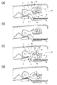
ここで、シャッタ部材6の構成について、図4を参照して動作とともに説明する。図4(a)は原稿Dを載置部1上に載置した状態を示す図であり、このときピックアップローラ3は上方の待機位置にある。このとき、シャッタ部材6は原稿給送口65を塞ぎ、原稿を堰き止める位置(原稿先端を規制する位置)にあって、ピックアップローラ3の軸に自由に回転可能に取り付けられたストッパ61により原稿給送方向への回動を規制されている。この状態で、原稿給送口65に原稿を進入させると、原稿Dの先端はシャッタ部材6の一端部に突き当たって、それ以上の進入が妨げられ、載置部1上の適正な位置に載置される。
Here, the configuration of the
その後、原稿給送信号により、ピックアップローラ3が下降するとシャッタ部材6に当接して規制するストッパ61が原稿給送口65の上側ガイドに設けられた突起部63と当接して上方に回動し、これによりストッパ61はシャッタ部材6から離間して原稿給送方向への規制が解除される(図4(b))。
After that, when the
ピックアップローラ3が所定量下降すると、支持アーム4に設けられた突起部62にシャッタ部材6の係止突起64が当接してシャッタ部材6を所定量回動させて原稿給送方向に傾けることとなる(図4(c))。このとき、シャッタ部材6は自重により垂下されているが、突起部62により所定量回動して傾いた位置で原稿給送方向上流側への回動を規制されているので、傾いた位置に保持された状態となる。
When the
そして、ピックアップローラ3が載置部1上の最上位原稿に当接し、ピックアップローラ3の回転により原稿が分離手段に向けて給送されると、給送される原稿の先端によってシャッタ部材6は原稿Dを通過させる位置まで押し上げられる。これにより、原稿Dがシャッタ部材6の位置を越えて分離部に送られる(図4(d))。このとき、シャッタ部材6の先端は繰り出される原稿の上面に自重により接触している。
Then, when the
また、ピックアップローラ3が給送位置から待機位置へ移動すると、シャッタ部材6は軸6aを中心にして自重により回動し、図4(a)の規制位置へ戻る。
Further, when the
(分離部)
前記シャッタ部材6よりも原稿給送方向下流側には、ピックアップローラ3によって給送された原稿Dを1枚ずつに分離して搬送する分離部が設けられている。この分離部は、給送された原稿を下流に搬送する搬送回転体である分離ローラ7と、この分離ローラ7に圧接する分離パッド8とを有している。載置部1に積載された原稿はピックアップローラ3により給送されるが、このとき上位の数枚が給送されることがある。この場合、分離部において回転する分離ローラ7と分離パッド8によってニップされることで最上位の1枚のみが分離されて下流へと搬送され、更に下流に配置された搬送ローラ対100によって搬送される。このときピックアップローラ3は待機位置に移動して搬送される原稿から離間し、搬送ローラ対100により原稿引き抜きの負荷にならないようになっている。
(Separation part)
On the downstream side of the
(駆動伝達手段)
次に前記ピックアップローラ3、支持アーム4、分離ローラ7を回転させるための駆動力の伝達構成について説明する。
(Drive transmission means)
Next, a driving force transmission structure for rotating the
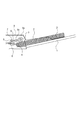
図5はピックアップローラ3及び分離ローラ7への駆動伝達構成を示す斜視説明図であり、図6は駆動伝達経路の模式説明図である。なお、図6において「>-<」形状はタイミングプーリを示し、「|-|」形状はギアを示す。また、図7は各センサによって検知された検知信号に応じて後述する駆動源である給送モータ30の駆動や電磁クラッチ52をオン、オフを制御する制御構成のブロック図である。
FIG. 5 is a perspective explanatory view showing a drive transmission structure to the
ピックアップローラ3は、分離ローラ7の駆動軸5に対して支持アーム4を介して揺動可能に支持されている。駆動軸5が図5の矢印A方向(第1の方向)に回転するとき、分離ローラ7も同時に回転し、原稿Dを分離搬送することができる。支持アーム4は、一端を駆動軸5に支持され、他端でピックアップローラ3を支持するピックアップ軸22を支持している。
The
駆動軸5には、駆動プーリ23、ピックアップ軸22には従動プーリ24が取り付けられており、タイミングベルト25が巻き掛けられている。
A
また、支持アーム4内には、ワンウェイクラッチ(不図示)が内蔵されており、駆動軸5が図5の矢印B方向(第2の方向)に回転するときは駆動軸5と共に回転し、駆動軸5が矢印A方向に回転するときは空転するようになっている。ここで、ピックアップローラ3が上方の待機位置にあり、原稿が載置された状態で原稿給送動作が開始されると、図6に示す駆動伝達手段50の中で、電磁クラッチ52が接続される。電磁クラッチ52は駆動源である給送モータ30からの駆動力を伝達又は遮断可能な入力伝達遮断クラッチとなるものである。
A one-way clutch (not shown) is built in the
前記電磁クラッチ52が接続されることにより、給送モータ30からの駆動力がプーリ30a、タイミングベルト54、プーリ53aと伝達する。そして、プーリ53aとギア部53bが一体となったギアプーリ53のギア部53bから電磁クラッチ52に含まれるギア52aに伝達される。そして、ギア連結軸52cからギア52bを介して、ギア51aに伝達され、逆入力遮断クラッチ51に駆動が伝達される。
By connecting the electromagnetic clutch 52, the driving force from the feeding
逆入力遮断クラッチ51は、給送モータ30から駆動軸前記駆動軸を前記第1の方向及び前記第2の方向に回転させる駆動力を伝達し、支持アーム4側から前記駆動軸5を回転させる逆入力トルクに対して前記駆動軸の回転をロックする双方向クラッチである。
The reverse input cutoff clutch 51 transmits a driving force for rotating the drive shaft in the first direction and the second direction from the
逆入力遮断クラッチ51から出力される駆動力は、ギア51bからギア部55aとギア部55bが一体的なアイドラギア55の前記ギア部55aに伝達される。そして、ギア部55bは駆動軸5の端部に取り付けられているギア20aとかみ合っているため、駆動軸5に駆動が伝達される。
The driving force output from the reverse
前記のようにして給送モータ30からの駆動力が駆動軸5に伝達されることにより、駆動軸5が図5に示す矢印A方向に回転して分離ローラ7がシートを搬送する方向に回転する。同時に支持アーム4によるピックアップローラ3を上方の待機位置で保持する回転力がなくなる。このため、ピックアップローラ3は自重で下降し、原稿と当接する給送位置に移動した後、タイミングベルト25を介して駆動軸5から回転力が伝達され、回転することで原稿の給送を開始する。
By transmitting the driving force from the feeding
給送された原稿Dが分離ローラ7と分離パッド8により1枚ずつ分離搬送され、シート先端が搬送ローラ対100のニップに達したことをニップ位置センサ40(図7参照)が検知すると、電磁クラッチ52が切断される。これにより、分離ローラ7を回転させる駆動力の伝達が遮断される。その後は搬送ローラ対100を駆動することによって原稿を下流に搬送する。
When the nip position sensor 40 (see FIG. 7) detects that the fed document D is separated and conveyed by the
電磁クラッチ52が切断されると、給送モータ30の駆動力は分離ローラ7に伝達されない。このため、搬送ローラ対100の駆動と分離ローラ7の駆動とを同一のモータで行うことができる。
When the
載置部1上に載置されたすべての原稿の給送が終了し、載置部1に原稿がないことを原稿載置検知センサ41(図7参照)が検知すると、制御部60は給送モータ30をシート給送時とは逆に回転させる。これと同時に、図5及び図6に示す駆動伝達手段の中で電磁クラッチ52を接続することで、駆動軸5が図5の矢印B方向に回転する。これにより、支持アーム4が駆動軸5とともに回転してピックアップローラ3が載置部1に当接した最下位置から待機位置まで上昇する量だけ駆動軸5を回転させた後、電磁クラッチ52を切断する。
When the document placement detection sensor 41 (see FIG. 7) detects that there is no document on the
電磁クラッチ52を切断することで、電磁クラッチ52から駆動伝達経路の下流では自由に回転することが可能になる。しかし、電磁クラッチ52から支持アーム4までの駆動伝達経路には逆入力遮断クラッチ51が設けられているため、駆動伝達経路における上流からの駆動力は下流に伝達することが可能であるが、下流から上流への駆動は遮断される。すなわち、逆入力遮断クラッチ51よりも駆動伝達経路で上流の軸を回転させると下流の軸は回転するが、下流の軸のみを回転させようとしても、逆入力遮断クラッチ51でロックされているために回転することはできない。
By disconnecting the electromagnetic clutch 52, the electromagnetic clutch 52 can be freely rotated downstream of the drive transmission path. However, since the reverse
従って、ピックアップローラ3を上方の待機位置まで上昇させた後、電磁クラッチ52を切ると、ピックアップローラ3の自重により、支持アーム4を介して駆動軸5を回転させて下降しようとする逆入力トルクが発生する。しかし、駆動系の下流側たる支持アーム4から駆動軸5を図5の矢印A方向に回転させる回転力は逆入力遮断クラッチ51でロックされる。このため、電磁クラッチ52が切断されても支持アーム4は回転しないため、ピックアップローラ3が下降することはない。
Therefore, when the
上記のように逆入力遮断クラッチ51を設けることにより、電磁クラッチ52を接続したまま給送モータ30を保持するための電力を使用することなく、ピックアップローラ3を待機位置でで保持することができる。
By providing the reverse input cutoff clutch 51 as described above, the
また、本実施形態の読取装置は、図1に示すように、ピックアップローラ3、分離ローラ7の上方には開閉部材である開閉カバー9が開閉可能に設けられており、原稿がジャムした場合等は前記開閉カバー9を開いてジャム処理できるようになっている。この開閉カバー9には前述した駆動伝達手段を構成するギアの一部が配置されている。このため、開閉カバー9を開くと、開閉カバーに設けられたギア20aと、これに噛合している本体に設けられたギア55bとが分離して噛合状態が解除される。したがって、ピックアップローラ3が上方に移動した待機位置にあるときに開閉カバー9を開くと、逆入力遮断クラッチ51によってピックアップローラ3を待機位置に保持することができなくなり、ピックアップローラ3は自重によって下降する。
Further, as shown in FIG. 1, the reading device of the present embodiment is provided with an opening/
ピックアップローラ3が下降すると、前述のように支持アーム4の回転に連動してシャッタ部材6は図3に示す非規制位置に移動する。仮に、開閉カバー9を閉じるときにシャッタ部材6が起立垂下した状態のままだと、載置部1に載置した原稿がシャッタ部材6の下部に移動してしまった場合、開閉カバー9を閉じたときにシャッタ先端が載置部1上の原稿に突き当たって原稿を傷めるおそれがある。これに対して本実施形態にあっては、開閉カバー9を閉じるときはシャッタ部材6が非規制位置にあるため(倒れた状態)、載置部1に載置した原稿がシャッタ部材6の下部に移動してしまってもシャッタ部材6が原稿に突き当たることがない。よって、開閉カバー9を閉じるときにシャッタ部材6によって原稿を傷めることはない。
When the
開閉カバー9が閉じると、カバー開閉検知センサ42(図7参照)によって検知され、この検知信号を受けて制御部60はピックアップローラ3を待機位置に移動させるように給送モータ30及び電磁クラッチ52を制御する。そして、ピックアップローラ3は前述のごとく逆入力遮断クラッチ51によって待機位置に保持される。
When the opening/
また、ピックアップローラ3の待機位置への移動により、シャッタ部材6は非規制位置から規制位置に戻る。なお、このとき原稿がシャッタ部材6の下部にあるときは、シャッタ部材6は原稿の上に自重で乗った状態になる。そして、原稿給送が終了した場合、または、原稿が載置部1から引き抜かれた場合等、シャッタ部材6の下部の原稿がなくなると、シャッタ部材6は自重で、起立した状態に戻り、その状態でロックされる。
Further, the movement of the
(ギア軸間の調整構成)
次に装置本体に設けられた給送モータ30から開閉カバー9に設けられたピックアップローラ3に駆動力を伝達する駆動伝達手段のギア列において、アイドラギア55のギア部55aと、ギア20aのギア間の調整構成について説明する。
(Adjustment configuration between gear shafts)
Next, in the gear train of the drive transmission means for transmitting the driving force from the feeding
図8乃至図11に示すように、ギア(第2ギア)20aは開閉カバー9に設けられ、アイドラギア(第1ギア)55は装置本体に設けられている。このため、開閉カバー9を開くと、ギア20aとアイドラギア55のギア部55aは離間し(図10参照)、開閉カバー9を閉じるとギア20aとギア部55aは噛合する(図9参照)。
As shown in FIGS. 8 to 11, the gear (second gear) 20a is provided on the opening/
前述のように、開閉カバー9は軸9bを回動中心にして回動して開閉可能であり、給送装置内に原稿か詰まった時等は開閉カバー9を開いて詰まった原稿にアクセスしやすい構成になっている。また、開閉カバー9にはシートを搬送するための第1搬送ローラとなる引抜コロ100a、レジストレーションコロ101aが設けられ、装置本体には開閉カバー9を閉じたときに前記第1搬送ローラと圧接する第2搬送ローラとなる引抜きローラ100b、レジストレーションローラ101bが設けられ、これらが圧接している。このため、開閉カバー9は閉じた状態では矢印a方向及び矢印b方向に反力を受けている。
As described above, the opening/
なお、開閉カバー9の開閉側(回動軸9bと反対側)には係止部であるフック部材70が設けられており、装置本体には前記フック部材70が係止可能な被係止部である係止軸80が設けられている。これにより、前記フック部材70を前記係止軸80に係止することで、前記反力を受けても開閉カバー9が開かないように保持される。
A
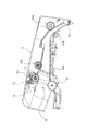
しかし、上記のように開閉カバー9がフック部材70でロックされた状態で前記搬送ローラ対の圧接による反力を受けると、図9の破線9cに示すように、変形し易くなっている。そして、開閉カバー9が破線9cに示すように変形すると、装置本体側に設けられているギア部55aと、開閉カバー9側に設けられているギア20aとの軸間が広がってしまい、駆動伝達が的確に行われなくなる可能性がある。
However, when the opening/
このため、本実施形態においては、図11に示すように、ギア部55aとギア20aとの軸間距離を調整するための調整部材としての調整板90が設けられている。この調整板90は前記フック部材70の回動中心となるフック軸71と同一軸上に回動可能に取り付けられ、この調整板90にギア20aを支持する軸5が保持されている。したがって、ギア20aは、フック軸71を中心に回動可能な調整板90の回動領域の範囲で移動可能に取り付けられている。
For this reason, in the present embodiment, as shown in FIG. 11, an adjusting
また、調整板90には、軸5を中心に円弧状の長穴90aが形成され、この長穴90aにネジ91を締結することで調整板90を所定位置で開閉カバー9に固定するようになっている。
Further, the
上記構成において、前述のように開閉カバー9が図9の破線9cのように変形し、ギア部55aとギア20aの軸間距離が変化したとする。このとき、調整板90を回動させてギア20aの位置を移動させることで前記軸間距離を調整することができる。開閉カバー9を閉じてフック部材70を係止軸80に係止した状態では、開閉カバー9が変形しても開閉カバー9に設けたフック軸71と装置本体に設けた係止軸80との距離は変化しない。そして、ギア20aは前記フック軸71と同一軸で回動可能な調整板90に取り付けられ、ギア55は前記係止軸80の近傍に配置されているため、開閉カバー9が変形して、例えばフック部材70がフック軸71を中心に反時計回りに回転したような状態になったとしても、調整板90をフック軸71を中心に時計回り(図11の矢印c方向)に回転させることで、ギア部55aとギア20aとの軸間距離を正規位置にすることができる。
In the above configuration, it is assumed that the opening/
なお、本実施形態にあっては、図12に示すように、ギア20aの回転軸5が正規位置にあるときに嵌るU字溝81が装置本体の筐体に形成されている。したがって、前記のように調整板90を回動させてギア20aの位置調整をするときに、回転軸5が前記U字溝81の底部81aに当接する位置まで回動させることにより、ギア部55aに対するギア20aの位置を容易に調整することができる。
In the present embodiment, as shown in FIG. 12, a
なお、前述した実施形態ではギア20aの位置を調整するときに、調整板90を回動して位置調整した後にネジ91によって固定するようにした。しかし、それ以外にも例えばバネによって付勢するようにしてもよい。
In the above-described embodiment, when adjusting the position of the
例えば、図13に示すように、フック軸71に付勢手段であるネジリコイルバネ92を取り付け、その一方側端部を調整板90に係止する。これにより、ギア20aがギア部55aの方向に付勢されるように構成する。また、ギア20aとギア55bはハス歯ギアであって、駆動力が伝達されたときにギアを回転軸方向に付勢する力が作用するが、ギア20a、55bを離間させる方向に作用する力は小さい。前記ネジリコイルバネ92による付勢力は前記ギア20a、55bを離間させる力より強く設定されているために、駆動力の伝達によって20a、55bが離間することはない。また、ネジ93は段つきネジであって調整板90との間に隙間を有し、調整板90の浮き上がりを規制している。
For example, as shown in FIG. 13, a
このように構成した場合には、ギア部55aとギア20aとの間隔が離間するように開閉カバー9が変形しても、調整板90がネジリコイルバネ92によって付勢され、開閉カバー9の変形に応じて調整板90が回動する。このため、ギア部55aとギア20aの軸間距離が一定に保持され駆動力の伝達が的確に行われる。
With this configuration, even if the opening/
また、前述した実施形態ではシート給送装置として、原稿を読取部に給送して原稿情報を読み取る読取装置を例示した。しかし、前述した構成のシート給送装置によりシートを画像形成部に給送し、画像形成部においてシートに画像を形成する画像形成装置にあっても用いることができる。 Further, in the above-described embodiment, as the sheet feeding device, the reading device that feeds the document to the reading unit and reads the document information is illustrated. However, it can also be used in an image forming apparatus that feeds a sheet to the image forming section by the sheet feeding apparatus having the above-described configuration and forms an image on the sheet in the image forming section.
A …読取装置
B …シート給送装置
3 …ピックアップローラ
4 …支持アーム
5 …駆動軸
9 …開閉カバー
9a …突当部
9b …軸
20a …ギア
30 …給送モータ
55 …アイドラギア
55a …ギア部
60 …制御部
70 …フック部材
70 …スプリングクラッチ
71 …フック軸
80 …係止軸
81 …U字溝
81a …底部
90 …調整板
90a …長穴
91 …ネジ
92 …ネジリコイルバネ
100,101,102,105 …搬送ローラ対
A... Reading device B...
Claims (8)
前記回転体を駆動する駆動力を発生させるモータと、
前記モータが設けられる装置本体に対して開閉可能であり且つ前記シートをガイドする搬送路を開放する開閉部材であって、前記回転体が設けられる開閉部材と、
前記装置本体に設けられ、前記モータの駆動力を伝達する第1ギアと、
前記開閉部材に設けられた第2ギアであって、前記開閉部材が閉じた状態では前記第1ギアと噛合して前記第1ギアからの駆動力を前記回転体に伝達し、前記開閉部材が開いた状態では前記第1ギアに対して離間する第2ギアと、
前記第2ギアの回動軸を保持する保持部を備え、前記保持部の位置を調整することによって前記第2ギアの回動軸の位置を調整する調整部材と、
前記開閉部材に回動可能に設けられ、前記開閉部材を閉じた状態で前記装置本体に設けられた被係止部に係止する係止部を有し、
前記保持部は、前記係止部の回動中心と同一軸上に回動可能に設けられることを特徴とするシート給送装置。 A rotating body that conveys sheets,
A motor for generating a driving force for driving the rotating body,
An opening/closing member that is openable/closable with respect to an apparatus main body provided with the motor and opens a conveyance path that guides the sheet, wherein the opening/closing member is provided with the rotating body,
A first gear that is provided in the apparatus body and that transmits the driving force of the motor;
A second gear provided on the opening/closing member, which meshes with the first gear when the opening/closing member is closed to transmit the driving force from the first gear to the rotating body. A second gear that is separated from the first gear in the opened state;
An adjusting member that includes a holding portion that holds the rotation shaft of the second gear, and that adjusts the position of the holding portion by adjusting the position of the holding portion;
A locking portion that is rotatably provided on the opening/closing member and that locks with a locked portion provided on the apparatus main body when the opening/closing member is closed;
The sheet feeding device , wherein the holding portion is rotatably provided on the same axis as the rotation center of the locking portion .
前記装置本体には、前記開閉部材が閉じたときに前記第1搬送ローラと圧接する第2搬送ローラが設けられていることを特徴とする請求項1又は2に記載のシート給送装置。 The opening/closing member is provided with a first transport roller for transporting the sheet, on the downstream side of the rotating body in the transport direction in which the sheet is transported,
The sheet feeding device according to claim 1, wherein the main body of the apparatus is provided with a second transport roller that comes into pressure contact with the first transport roller when the opening/closing member is closed.
前記シートを積載する積載部と、
前記積載部に積載されたシートを給送する第2回転体と、
前記回転体とニップ部を構成し、前記第2回転体によって重なった状態で搬送された複数枚のシートを前記ニップ部において分離する分離部材と、
を有することを特徴とする請求項1乃至4のいずれか一項に記載のシート給送装置。 The sheet feeding device,
A stacking unit for stacking the sheets,
A second rotating body for feeding the sheets stacked on the stacking unit;
A separating member that forms a nip portion with the rotating body and separates a plurality of sheets conveyed in the state of being overlapped by the second rotating body at the nip portion;
The sheet feeding device according to any one of claims 1 to 4, further comprising:
給送されたシートに記載された情報を読み取る読取部と、
を有することを特徴とする読取装置。 A sheet feeding device according to any one of claims 1 to 6,
A reading unit for reading the information written on the fed sheet,
A reading device comprising:
給送されたシートに画像を形成する画像形成部と、
を有することを特徴とする画像形成装置。 A sheet feeding device according to any one of claims 1 to 6,
An image forming unit that forms an image on the fed sheet,
An image forming apparatus comprising:
Priority Applications (1)
| Application Number | Priority Date | Filing Date | Title |
|---|---|---|---|
| JP2016109293A JP6746381B2 (en) | 2016-05-31 | 2016-05-31 | Sheet feeding apparatus, reading apparatus including the same, and image forming apparatus |
Applications Claiming Priority (1)
| Application Number | Priority Date | Filing Date | Title |
|---|---|---|---|
| JP2016109293A JP6746381B2 (en) | 2016-05-31 | 2016-05-31 | Sheet feeding apparatus, reading apparatus including the same, and image forming apparatus |
Publications (3)
| Publication Number | Publication Date |
|---|---|
| JP2017214193A JP2017214193A (en) | 2017-12-07 |
| JP2017214193A5 JP2017214193A5 (en) | 2019-06-13 |
| JP6746381B2 true JP6746381B2 (en) | 2020-08-26 |
Family
ID=60575276
Family Applications (1)
| Application Number | Title | Priority Date | Filing Date |
|---|---|---|---|
| JP2016109293A Active JP6746381B2 (en) | 2016-05-31 | 2016-05-31 | Sheet feeding apparatus, reading apparatus including the same, and image forming apparatus |
Country Status (1)
| Country | Link |
|---|---|
| JP (1) | JP6746381B2 (en) |
Families Citing this family (2)
| Publication number | Priority date | Publication date | Assignee | Title |
|---|---|---|---|---|
| JP7467140B2 (en) | 2020-01-31 | 2024-04-15 | キヤノン株式会社 | Image reader |
| CN117358353B (en) * | 2023-10-17 | 2024-04-12 | 东莞市铁石文档科技有限公司 | Anti-blocking paper shredder based on automatic reverse direction |
Family Cites Families (4)
| Publication number | Priority date | Publication date | Assignee | Title |
|---|---|---|---|---|
| JP3592459B2 (en) * | 1996-08-30 | 2004-11-24 | 株式会社リコー | Open / close type power transmission device in image forming apparatus |
| JP2006082885A (en) * | 2004-09-14 | 2006-03-30 | Canon Inc | Automatic document feeder |
| JP2007261698A (en) * | 2006-03-27 | 2007-10-11 | Kyocera Mita Corp | Sheet conveying device and image reading device provided therewith |
| JP6313535B2 (en) * | 2012-08-27 | 2018-04-18 | ゼロックス コーポレイションXerox Corporation | Paper feeder |
-
2016
- 2016-05-31 JP JP2016109293A patent/JP6746381B2/en active Active
Also Published As
| Publication number | Publication date |
|---|---|
| JP2017214193A (en) | 2017-12-07 |
Similar Documents
| Publication | Publication Date | Title |
|---|---|---|
| US6547235B2 (en) | Sheet sorting apparatus and automatic document feeder apparatus including the same | |
| JP5532514B2 (en) | Paper feeding device, image reading device, and image forming device | |
| JP5213529B2 (en) | Image processing device | |
| EP2889240A1 (en) | Paper supply device | |
| JP6163469B2 (en) | Manual sheet feeding apparatus and image forming apparatus having the same | |
| JP6746381B2 (en) | Sheet feeding apparatus, reading apparatus including the same, and image forming apparatus | |
| JP4907460B2 (en) | Automatic document feeder and image forming apparatus | |
| JP2006306603A (en) | Sheet handling device and image forming device | |
| US6810231B2 (en) | Sheet transfer apparatus and image reading apparatus | |
| JP2012246122A (en) | Sheet conveying apparatus, image reading apparatus, and image forming apparatus | |
| JP6004776B2 (en) | Sheet feeding apparatus, image reading apparatus, and image forming apparatus | |
| JP2010228848A (en) | Paper feeding device and document feeding device using the same | |
| JP5168021B2 (en) | Automatic document feeder and image forming apparatus | |
| JP4306688B2 (en) | Automatic document feeder | |
| JP6602070B2 (en) | Sheet feeding apparatus, reading apparatus including the same, and image forming apparatus | |
| JP2017222513A (en) | Transportation device, image reading device and image formation device | |
| JP2011133663A (en) | Paper feeding device and image forming apparatus | |
| JP7387428B2 (en) | Sheet storage device and sheet feeding device | |
| JPH0930658A (en) | Hand-set sheet feeding device and image forming device | |
| JP7451201B2 (en) | Sheet feeding device and image reading device | |
| JP5216548B2 (en) | Sheet conveying apparatus and image reading apparatus | |
| JP5282668B2 (en) | Manual paper feeder and image forming apparatus | |
| JP2007254148A (en) | Automatic document conveying device | |
| JP2872436B2 (en) | Image forming apparatus having re-feeding device | |
| JP2015229537A (en) | Sheet conveyance device, image reading device, and image formation device |
Legal Events
| Date | Code | Title | Description |
|---|---|---|---|
| A521 | Written amendment |
Free format text: JAPANESE INTERMEDIATE CODE: A523 Effective date: 20190508 |
|
| A621 | Written request for application examination |
Free format text: JAPANESE INTERMEDIATE CODE: A621 Effective date: 20190508 |
|
| A977 | Report on retrieval |
Free format text: JAPANESE INTERMEDIATE CODE: A971007 Effective date: 20200309 |
|
| A131 | Notification of reasons for refusal |
Free format text: JAPANESE INTERMEDIATE CODE: A131 Effective date: 20200414 |
|
| A521 | Written amendment |
Free format text: JAPANESE INTERMEDIATE CODE: A523 Effective date: 20200527 |
|
| TRDD | Decision of grant or rejection written | ||
| A01 | Written decision to grant a patent or to grant a registration (utility model) |
Free format text: JAPANESE INTERMEDIATE CODE: A01 Effective date: 20200707 |
|
| A61 | First payment of annual fees (during grant procedure) |
Free format text: JAPANESE INTERMEDIATE CODE: A61 Effective date: 20200805 |
|
| R151 | Written notification of patent or utility model registration |
Ref document number: 6746381 Country of ref document: JP Free format text: JAPANESE INTERMEDIATE CODE: R151 |