JP6745762B2 - System and method for providing real-time signal partitioning and fiducial alignment framework - Google Patents
System and method for providing real-time signal partitioning and fiducial alignment framework Download PDFInfo
- Publication number
- JP6745762B2 JP6745762B2 JP2017117509A JP2017117509A JP6745762B2 JP 6745762 B2 JP6745762 B2 JP 6745762B2 JP 2017117509 A JP2017117509 A JP 2017117509A JP 2017117509 A JP2017117509 A JP 2017117509A JP 6745762 B2 JP6745762 B2 JP 6745762B2
- Authority
- JP
- Japan
- Prior art keywords
- signal
- segment
- signal segment
- reference point
- time
- Prior art date
- Legal status (The legal status is an assumption and is not a legal conclusion. Google has not performed a legal analysis and makes no representation as to the accuracy of the status listed.)
- Active
Links
- 238000000034 method Methods 0.000 title claims description 66
- 238000000638 solvent extraction Methods 0.000 title description 2
- 238000001514 detection method Methods 0.000 claims description 27
- 238000012545 processing Methods 0.000 claims description 21
- 230000008569 process Effects 0.000 claims description 15
- 230000006870 function Effects 0.000 claims description 13
- 238000009610 ballistocardiography Methods 0.000 claims description 8
- 230000003044 adaptive effect Effects 0.000 claims description 6
- 238000012544 monitoring process Methods 0.000 claims description 6
- 238000001914 filtration Methods 0.000 claims description 4
- 238000007781 pre-processing Methods 0.000 claims description 3
- 238000004891 communication Methods 0.000 description 14
- 238000003745 diagnosis Methods 0.000 description 8
- 238000010586 diagram Methods 0.000 description 8
- 238000000354 decomposition reaction Methods 0.000 description 7
- 238000005259 measurement Methods 0.000 description 6
- 230000036772 blood pressure Effects 0.000 description 5
- 230000029058 respiratory gaseous exchange Effects 0.000 description 5
- 210000000707 wrist Anatomy 0.000 description 5
- 238000005070 sampling Methods 0.000 description 4
- 230000011218 segmentation Effects 0.000 description 4
- 238000004458 analytical method Methods 0.000 description 3
- 238000013459 approach Methods 0.000 description 3
- 206010003119 arrhythmia Diseases 0.000 description 3
- 230000003111 delayed effect Effects 0.000 description 3
- 230000003287 optical effect Effects 0.000 description 3
- 208000008784 apnea Diseases 0.000 description 2
- 230000000694 effects Effects 0.000 description 2
- 230000004660 morphological change Effects 0.000 description 2
- 230000000241 respiratory effect Effects 0.000 description 2
- 230000036387 respiratory rate Effects 0.000 description 2
- 230000004044 response Effects 0.000 description 2
- 238000003491 array Methods 0.000 description 1
- 230000006793 arrhythmia Effects 0.000 description 1
- 230000036760 body temperature Effects 0.000 description 1
- 238000004364 calculation method Methods 0.000 description 1
- 230000000747 cardiac effect Effects 0.000 description 1
- 238000006243 chemical reaction Methods 0.000 description 1
- 238000005352 clarification Methods 0.000 description 1
- 238000004590 computer program Methods 0.000 description 1
- 238000010276 construction Methods 0.000 description 1
- 230000008602 contraction Effects 0.000 description 1
- 238000013461 design Methods 0.000 description 1
- 210000005069 ears Anatomy 0.000 description 1
- 230000002526 effect on cardiovascular system Effects 0.000 description 1
- 238000005516 engineering process Methods 0.000 description 1
- 210000000245 forearm Anatomy 0.000 description 1
- 230000004927 fusion Effects 0.000 description 1
- 230000036541 health Effects 0.000 description 1
- 239000011159 matrix material Substances 0.000 description 1
- 230000000877 morphologic effect Effects 0.000 description 1
- 238000005457 optimization Methods 0.000 description 1
- 231100000430 skin reaction Toxicity 0.000 description 1
- 230000008667 sleep stage Effects 0.000 description 1
- 238000001228 spectrum Methods 0.000 description 1
- 238000010183 spectrum analysis Methods 0.000 description 1
- 230000001629 suppression Effects 0.000 description 1
- 230000026676 system process Effects 0.000 description 1
- 230000002123 temporal effect Effects 0.000 description 1
- 230000001960 triggered effect Effects 0.000 description 1
Images


Classifications
-
- A—HUMAN NECESSITIES
- A61—MEDICAL OR VETERINARY SCIENCE; HYGIENE
- A61B—DIAGNOSIS; SURGERY; IDENTIFICATION
- A61B5/00—Measuring for diagnostic purposes; Identification of persons
- A61B5/72—Signal processing specially adapted for physiological signals or for diagnostic purposes
- A61B5/7271—Specific aspects of physiological measurement analysis
- A61B5/7278—Artificial waveform generation or derivation, e.g. synthesising signals from measured signals
-
- A—HUMAN NECESSITIES
- A61—MEDICAL OR VETERINARY SCIENCE; HYGIENE
- A61B—DIAGNOSIS; SURGERY; IDENTIFICATION
- A61B5/00—Measuring for diagnostic purposes; Identification of persons
- A61B5/02—Detecting, measuring or recording pulse, heart rate, blood pressure or blood flow; Combined pulse/heart-rate/blood pressure determination; Evaluating a cardiovascular condition not otherwise provided for, e.g. using combinations of techniques provided for in this group with electrocardiography or electroauscultation; Heart catheters for measuring blood pressure
- A61B5/021—Measuring pressure in heart or blood vessels
-
- A—HUMAN NECESSITIES
- A61—MEDICAL OR VETERINARY SCIENCE; HYGIENE
- A61B—DIAGNOSIS; SURGERY; IDENTIFICATION
- A61B5/00—Measuring for diagnostic purposes; Identification of persons
- A61B5/72—Signal processing specially adapted for physiological signals or for diagnostic purposes
- A61B5/7235—Details of waveform analysis
- A61B5/7246—Details of waveform analysis using correlation, e.g. template matching or determination of similarity
-
- A—HUMAN NECESSITIES
- A61—MEDICAL OR VETERINARY SCIENCE; HYGIENE
- A61B—DIAGNOSIS; SURGERY; IDENTIFICATION
- A61B5/00—Measuring for diagnostic purposes; Identification of persons
- A61B5/0002—Remote monitoring of patients using telemetry, e.g. transmission of vital signals via a communication network
- A61B5/0015—Remote monitoring of patients using telemetry, e.g. transmission of vital signals via a communication network characterised by features of the telemetry system
- A61B5/0022—Monitoring a patient using a global network, e.g. telephone networks, internet
-
- A—HUMAN NECESSITIES
- A61—MEDICAL OR VETERINARY SCIENCE; HYGIENE
- A61B—DIAGNOSIS; SURGERY; IDENTIFICATION
- A61B5/00—Measuring for diagnostic purposes; Identification of persons
- A61B5/02—Detecting, measuring or recording pulse, heart rate, blood pressure or blood flow; Combined pulse/heart-rate/blood pressure determination; Evaluating a cardiovascular condition not otherwise provided for, e.g. using combinations of techniques provided for in this group with electrocardiography or electroauscultation; Heart catheters for measuring blood pressure
- A61B5/024—Detecting, measuring or recording pulse rate or heart rate
- A61B5/02405—Determining heart rate variability
-
- A—HUMAN NECESSITIES
- A61—MEDICAL OR VETERINARY SCIENCE; HYGIENE
- A61B—DIAGNOSIS; SURGERY; IDENTIFICATION
- A61B5/00—Measuring for diagnostic purposes; Identification of persons
- A61B5/02—Detecting, measuring or recording pulse, heart rate, blood pressure or blood flow; Combined pulse/heart-rate/blood pressure determination; Evaluating a cardiovascular condition not otherwise provided for, e.g. using combinations of techniques provided for in this group with electrocardiography or electroauscultation; Heart catheters for measuring blood pressure
- A61B5/024—Detecting, measuring or recording pulse rate or heart rate
- A61B5/02416—Detecting, measuring or recording pulse rate or heart rate using photoplethysmograph signals, e.g. generated by infrared radiation
-
- A—HUMAN NECESSITIES
- A61—MEDICAL OR VETERINARY SCIENCE; HYGIENE
- A61B—DIAGNOSIS; SURGERY; IDENTIFICATION
- A61B5/00—Measuring for diagnostic purposes; Identification of persons
- A61B5/05—Detecting, measuring or recording for diagnosis by means of electric currents or magnetic fields; Measuring using microwaves or radio waves
- A61B5/053—Measuring electrical impedance or conductance of a portion of the body
- A61B5/0531—Measuring skin impedance
- A61B5/0533—Measuring galvanic skin response
-
- A—HUMAN NECESSITIES
- A61—MEDICAL OR VETERINARY SCIENCE; HYGIENE
- A61B—DIAGNOSIS; SURGERY; IDENTIFICATION
- A61B5/00—Measuring for diagnostic purposes; Identification of persons
- A61B5/08—Detecting, measuring or recording devices for evaluating the respiratory organs
- A61B5/0816—Measuring devices for examining respiratory frequency
-
- A—HUMAN NECESSITIES
- A61—MEDICAL OR VETERINARY SCIENCE; HYGIENE
- A61B—DIAGNOSIS; SURGERY; IDENTIFICATION
- A61B5/00—Measuring for diagnostic purposes; Identification of persons
- A61B5/103—Detecting, measuring or recording devices for testing the shape, pattern, colour, size or movement of the body or parts thereof, for diagnostic purposes
- A61B5/11—Measuring movement of the entire body or parts thereof, e.g. head or hand tremor, mobility of a limb
- A61B5/1102—Ballistocardiography
-
- A—HUMAN NECESSITIES
- A61—MEDICAL OR VETERINARY SCIENCE; HYGIENE
- A61B—DIAGNOSIS; SURGERY; IDENTIFICATION
- A61B5/00—Measuring for diagnostic purposes; Identification of persons
- A61B5/24—Detecting, measuring or recording bioelectric or biomagnetic signals of the body or parts thereof
- A61B5/316—Modalities, i.e. specific diagnostic methods
- A61B5/318—Heart-related electrical modalities, e.g. electrocardiography [ECG]
- A61B5/346—Analysis of electrocardiograms
- A61B5/349—Detecting specific parameters of the electrocardiograph cycle
- A61B5/352—Detecting R peaks, e.g. for synchronising diagnostic apparatus; Estimating R-R interval
-
- A—HUMAN NECESSITIES
- A61—MEDICAL OR VETERINARY SCIENCE; HYGIENE
- A61B—DIAGNOSIS; SURGERY; IDENTIFICATION
- A61B5/00—Measuring for diagnostic purposes; Identification of persons
- A61B5/48—Other medical applications
- A61B5/4806—Sleep evaluation
- A61B5/4818—Sleep apnoea
-
- A—HUMAN NECESSITIES
- A61—MEDICAL OR VETERINARY SCIENCE; HYGIENE
- A61B—DIAGNOSIS; SURGERY; IDENTIFICATION
- A61B5/00—Measuring for diagnostic purposes; Identification of persons
- A61B5/68—Arrangements of detecting, measuring or recording means, e.g. sensors, in relation to patient
- A61B5/6801—Arrangements of detecting, measuring or recording means, e.g. sensors, in relation to patient specially adapted to be attached to or worn on the body surface
- A61B5/6802—Sensor mounted on worn items
- A61B5/681—Wristwatch-type devices
-
- A—HUMAN NECESSITIES
- A61—MEDICAL OR VETERINARY SCIENCE; HYGIENE
- A61B—DIAGNOSIS; SURGERY; IDENTIFICATION
- A61B5/00—Measuring for diagnostic purposes; Identification of persons
- A61B5/72—Signal processing specially adapted for physiological signals or for diagnostic purposes
- A61B5/7203—Signal processing specially adapted for physiological signals or for diagnostic purposes for noise prevention, reduction or removal
- A61B5/7207—Signal processing specially adapted for physiological signals or for diagnostic purposes for noise prevention, reduction or removal of noise induced by motion artifacts
- A61B5/721—Signal processing specially adapted for physiological signals or for diagnostic purposes for noise prevention, reduction or removal of noise induced by motion artifacts using a separate sensor to detect motion or using motion information derived from signals other than the physiological signal to be measured
-
- A—HUMAN NECESSITIES
- A61—MEDICAL OR VETERINARY SCIENCE; HYGIENE
- A61B—DIAGNOSIS; SURGERY; IDENTIFICATION
- A61B5/00—Measuring for diagnostic purposes; Identification of persons
- A61B5/72—Signal processing specially adapted for physiological signals or for diagnostic purposes
- A61B5/7235—Details of waveform analysis
- A61B5/725—Details of waveform analysis using specific filters therefor, e.g. Kalman or adaptive filters
-
- A—HUMAN NECESSITIES
- A61—MEDICAL OR VETERINARY SCIENCE; HYGIENE
- A61B—DIAGNOSIS; SURGERY; IDENTIFICATION
- A61B5/00—Measuring for diagnostic purposes; Identification of persons
- A61B5/72—Signal processing specially adapted for physiological signals or for diagnostic purposes
- A61B5/7235—Details of waveform analysis
- A61B5/7253—Details of waveform analysis characterised by using transforms
- A61B5/726—Details of waveform analysis characterised by using transforms using Wavelet transforms
-
- A—HUMAN NECESSITIES
- A61—MEDICAL OR VETERINARY SCIENCE; HYGIENE
- A61B—DIAGNOSIS; SURGERY; IDENTIFICATION
- A61B5/00—Measuring for diagnostic purposes; Identification of persons
- A61B5/72—Signal processing specially adapted for physiological signals or for diagnostic purposes
- A61B5/7235—Details of waveform analysis
- A61B5/7264—Classification of physiological signals or data, e.g. using neural networks, statistical classifiers, expert systems or fuzzy systems
-
- A—HUMAN NECESSITIES
- A61—MEDICAL OR VETERINARY SCIENCE; HYGIENE
- A61B—DIAGNOSIS; SURGERY; IDENTIFICATION
- A61B5/00—Measuring for diagnostic purposes; Identification of persons
- A61B5/72—Signal processing specially adapted for physiological signals or for diagnostic purposes
- A61B5/7271—Specific aspects of physiological measurement analysis
- A61B5/7282—Event detection, e.g. detecting unique waveforms indicative of a medical condition
-
- A—HUMAN NECESSITIES
- A61—MEDICAL OR VETERINARY SCIENCE; HYGIENE
- A61B—DIAGNOSIS; SURGERY; IDENTIFICATION
- A61B5/00—Measuring for diagnostic purposes; Identification of persons
- A61B5/74—Details of notification to user or communication with user or patient ; user input means
- A61B5/742—Details of notification to user or communication with user or patient ; user input means using visual displays
-
- A—HUMAN NECESSITIES
- A61—MEDICAL OR VETERINARY SCIENCE; HYGIENE
- A61B—DIAGNOSIS; SURGERY; IDENTIFICATION
- A61B2562/00—Details of sensors; Constructional details of sensor housings or probes; Accessories for sensors
- A61B2562/02—Details of sensors specially adapted for in-vivo measurements
- A61B2562/0219—Inertial sensors, e.g. accelerometers, gyroscopes, tilt switches
-
- A—HUMAN NECESSITIES
- A61—MEDICAL OR VETERINARY SCIENCE; HYGIENE
- A61B—DIAGNOSIS; SURGERY; IDENTIFICATION
- A61B5/00—Measuring for diagnostic purposes; Identification of persons
- A61B5/01—Measuring temperature of body parts ; Diagnostic temperature sensing, e.g. for malignant or inflamed tissue
-
- A—HUMAN NECESSITIES
- A61—MEDICAL OR VETERINARY SCIENCE; HYGIENE
- A61B—DIAGNOSIS; SURGERY; IDENTIFICATION
- A61B5/00—Measuring for diagnostic purposes; Identification of persons
- A61B5/02—Detecting, measuring or recording pulse, heart rate, blood pressure or blood flow; Combined pulse/heart-rate/blood pressure determination; Evaluating a cardiovascular condition not otherwise provided for, e.g. using combinations of techniques provided for in this group with electrocardiography or electroauscultation; Heart catheters for measuring blood pressure
- A61B5/0205—Simultaneously evaluating both cardiovascular conditions and different types of body conditions, e.g. heart and respiratory condition
- A61B5/02055—Simultaneously evaluating both cardiovascular condition and temperature
-
- A—HUMAN NECESSITIES
- A61—MEDICAL OR VETERINARY SCIENCE; HYGIENE
- A61B—DIAGNOSIS; SURGERY; IDENTIFICATION
- A61B5/00—Measuring for diagnostic purposes; Identification of persons
- A61B5/48—Other medical applications
- A61B5/4806—Sleep evaluation
- A61B5/4812—Detecting sleep stages or cycles
-
- A—HUMAN NECESSITIES
- A61—MEDICAL OR VETERINARY SCIENCE; HYGIENE
- A61B—DIAGNOSIS; SURGERY; IDENTIFICATION
- A61B5/00—Measuring for diagnostic purposes; Identification of persons
- A61B5/68—Arrangements of detecting, measuring or recording means, e.g. sensors, in relation to patient
- A61B5/6801—Arrangements of detecting, measuring or recording means, e.g. sensors, in relation to patient specially adapted to be attached to or worn on the body surface
- A61B5/6813—Specially adapted to be attached to a specific body part
- A61B5/6823—Trunk, e.g., chest, back, abdomen, hip
-
- A—HUMAN NECESSITIES
- A61—MEDICAL OR VETERINARY SCIENCE; HYGIENE
- A61B—DIAGNOSIS; SURGERY; IDENTIFICATION
- A61B5/00—Measuring for diagnostic purposes; Identification of persons
- A61B5/68—Arrangements of detecting, measuring or recording means, e.g. sensors, in relation to patient
- A61B5/6801—Arrangements of detecting, measuring or recording means, e.g. sensors, in relation to patient specially adapted to be attached to or worn on the body surface
- A61B5/6813—Specially adapted to be attached to a specific body part
- A61B5/6824—Arm or wrist
-
- A—HUMAN NECESSITIES
- A61—MEDICAL OR VETERINARY SCIENCE; HYGIENE
- A61B—DIAGNOSIS; SURGERY; IDENTIFICATION
- A61B5/00—Measuring for diagnostic purposes; Identification of persons
- A61B5/68—Arrangements of detecting, measuring or recording means, e.g. sensors, in relation to patient
- A61B5/6801—Arrangements of detecting, measuring or recording means, e.g. sensors, in relation to patient specially adapted to be attached to or worn on the body surface
- A61B5/6813—Specially adapted to be attached to a specific body part
- A61B5/6828—Leg
-
- G—PHYSICS
- G16—INFORMATION AND COMMUNICATION TECHNOLOGY [ICT] SPECIALLY ADAPTED FOR SPECIFIC APPLICATION FIELDS
- G16H—HEALTHCARE INFORMATICS, i.e. INFORMATION AND COMMUNICATION TECHNOLOGY [ICT] SPECIALLY ADAPTED FOR THE HANDLING OR PROCESSING OF MEDICAL OR HEALTHCARE DATA
- G16H50/00—ICT specially adapted for medical diagnosis, medical simulation or medical data mining; ICT specially adapted for detecting, monitoring or modelling epidemics or pandemics
- G16H50/20—ICT specially adapted for medical diagnosis, medical simulation or medical data mining; ICT specially adapted for detecting, monitoring or modelling epidemics or pandemics for computer-aided diagnosis, e.g. based on medical expert systems
Landscapes
- Health & Medical Sciences (AREA)
- Life Sciences & Earth Sciences (AREA)
- Engineering & Computer Science (AREA)
- Physics & Mathematics (AREA)
- Public Health (AREA)
- Veterinary Medicine (AREA)
- General Health & Medical Sciences (AREA)
- Animal Behavior & Ethology (AREA)
- Surgery (AREA)
- Biophysics (AREA)
- Pathology (AREA)
- Biomedical Technology (AREA)
- Heart & Thoracic Surgery (AREA)
- Medical Informatics (AREA)
- Molecular Biology (AREA)
- Physiology (AREA)
- Cardiology (AREA)
- Signal Processing (AREA)
- Artificial Intelligence (AREA)
- Psychiatry (AREA)
- Computer Vision & Pattern Recognition (AREA)
- Dermatology (AREA)
- Pulmonology (AREA)
- Dentistry (AREA)
- Oral & Maxillofacial Surgery (AREA)
- Radiology & Medical Imaging (AREA)
- Nuclear Medicine, Radiotherapy & Molecular Imaging (AREA)
- Vascular Medicine (AREA)
- Fuzzy Systems (AREA)
- Mathematical Physics (AREA)
- Evolutionary Computation (AREA)
- Computer Networks & Wireless Communication (AREA)
- Measurement And Recording Of Electrical Phenomena And Electrical Characteristics Of The Living Body (AREA)
- Measuring Pulse, Heart Rate, Blood Pressure Or Blood Flow (AREA)
- Measuring And Recording Apparatus For Diagnosis (AREA)
- Measurement Of The Respiration, Hearing Ability, Form, And Blood Characteristics Of Living Organisms (AREA)
Description
本発明は使用者の生体信号の測定に係り、さらに具体的には、実時間信号分割(real−time signal segmentation)及び基準点整列フレームワーク(fiducial points alignment framework)を提供するシステム及び方法に係る。 The present invention relates to a measurement of a user's biological signal, and more particularly, to a system and method for providing real-time signal segmentation and fiducial points alignment framework. ..
携帯用電子機器においては何れの場合にも、生体信号をモニタする着用型(wearable)センサ装置が望む生体信号を正確に検出することが望ましい。しかし、使用者の動き、検出された信号の複雑性、及び検出された信号内の雑音は、生体信号の正確な検出を往々にして困難にする。
従来のビート(拍動、beat)検出方法は通常、多様なタイプの測定センサからの健康測定結果(例えば、心臓拍動、呼吸数)を決定するのに使用される。この測定センサは、例えばBCG(ballistocardiography、心弾動図)信号、PPG(photoplethysmogram、光電式容積脈波図)信号、ECG(electrocardiogram、心電図)信号、GSR(galvanic skin response、電気皮膚反応)信号及び生体インピーダンス信号のような多様なタイプのセンサ信号を測定する。このような従来のビート検出方法は正確な検出性能を提供できず、雑音が含まれた信号(noizy_signal、以下、「雑音信号」という)上の特徴点(feature points)を高い信頼度をもって識別できない。
In any case of the portable electronic device, it is desirable to accurately detect the biological signal desired by the wearable sensor device that monitors the biological signal. However, user motion, detected signal complexity, and noise in the detected signal often make accurate detection of vital signs difficult.
Conventional beat detection methods are typically used to determine health measurements (eg, heart beat, respiratory rate) from various types of measurement sensors. This measurement sensor is, for example, a BCG (ballistocardiography, electrocardiogram) signal, a PPG (photoplethysmogram, photoplethysmogram) signal, an ECG (electrocardiogram, electrocardiogram) signal, a GSR (galvanic skin electrokinetic response), and a GSR (galvanic skin electrokinetic response). It measures various types of sensor signals, such as bioimpedance signals. Such a conventional beat detection method cannot provide accurate detection performance and cannot reliably identify feature points on a signal including noise (noise_signal, hereinafter referred to as “noise signal”). ..
本発明の目的は、生体信号の正確なビート検出を可能にする実時間信号分割(セグメンテーション、segmentation)及び基準点整列フレームワークを提供するシステム及び方法を提供することにある。 It is an object of the present invention to provide a system and method that provides a real-time signal segmentation and fiducial alignment framework that enables accurate beat detection of biological signals.
例示的な実施形態は、使用者から少なくとも1つのチャネルを通じて受信された第1信号に対する信号タイプを決定する方法を含み、ここで第1信号は使用者の生体信号である。第2信号は第1信号から提供され、第2信号は第1信号セグメント及び第2信号セグメントを形成するように分割される。 Example embodiments include a method of determining a signal type for a first signal received from a user through at least one channel, where the first signal is a biometric signal of the user. The second signal is provided from the first signal and the second signal is split to form the first signal segment and the second signal segment.
第1信号セグメント及び第2信号セグメントは信号タイプに基づいて処理されて第1信号セグメント及び第2信号セグメントの各々に対する基準点を決定する。信号タイプが第1タイプである場合、基準点は第1信号セグメント及び第2信号セグメントの各々に対して直接決定される。信号タイプが第2タイプである場合、第1イベント位置は第1信号セグメントから決定され、第1イベント位置は第1信号セグメントに対する基準点として識別される。 The first signal segment and the second signal segment are processed based on the signal type to determine a reference point for each of the first signal segment and the second signal segment. If the signal type is the first type, the reference point is directly determined for each of the first signal segment and the second signal segment. If the signal type is the second type, the first event position is determined from the first signal segment and the first event position is identified as a reference point for the first signal segment.
第2信号セグメントからの1つ以上の隣接点は第1信号セグメントに対する基準点とマッチングされ、隣接点の中で1つは第1信号セグメントに対する基準点に対応する第2信号セグメントに対する基準点として選択される。その次に、基準点を使用して第3信号が生成される。 One or more adjacent points from the second signal segment are matched with reference points for the first signal segment, one of the adjacent points being a reference point for the second signal segment corresponding to the reference point for the first signal segment. To be selected. Then, a third signal is generated using the reference point.
他の例示的な実施形態は実行される時、コンピューティングシステムによって動作を制御するようにする機械実行可能命令を格納する非一時的機械読出し可能媒体を含み、前記命令は使用者から少なくとも1つのチャネルを通じて受信された第1信号の信号タイプを決定する。第1信号は使用者の生体信号である。第2信号は第1信号から提供され、第2信号は第1信号と異なるか、或いは第1信号と実質的に同一である。第2信号は第1信号セグメント及び第2信号セグメントを形成するように分割されることができる。その後、第1信号セグメント及び第2信号セグメントは信号タイプに基づいて処理されて第1信号セグメント及び第2信号セグメントの各々に対する基準点を決定し、第3信号は基準点を使用して生成される。 Another exemplary embodiment includes a non-transitory machine-readable medium that stores machine-executable instructions that, when executed, cause the computer system to control operations, the instructions including at least one instruction from a user. Determine the signal type of the first signal received over the channel. The first signal is a biological signal of the user. The second signal is provided from the first signal and the second signal is different from or substantially the same as the first signal. The second signal can be split to form a first signal segment and a second signal segment. Then, the first signal segment and the second signal segment are processed based on the signal type to determine a reference point for each of the first signal segment and the second signal segment, and the third signal is generated using the reference point. It
その他の例示的な実施形態は使用者から第1信号を獲得するように構成された少なくとも1つのセンサを含むシステムを含み、ここで、センサは少なくとも1つのチャネルを有し、第1信号はチャネルの中で1つのチャネルを通じて受信される。診断プロセッサは第1信号の信号タイプを決定し、第1信号から第2信号を提供し、第1信号セグメント及び第2信号セグメントを形成するように第2信号を分割し、信号タイプに基づいて、第1信号セグメント及び第2信号セグメントの各々に対する基準点を決定する。 Other exemplary embodiments include a system that includes at least one sensor configured to obtain a first signal from a user, where the sensor has at least one channel and the first signal is the channel. In one channel. The diagnostic processor determines a signal type of the first signal, provides a second signal from the first signal, divides the second signal to form a first signal segment and a second signal segment, and based on the signal type , A reference point for each of the first signal segment and the second signal segment.
信号タイプが第1タイプである場合、診断プロセッサは第1信号セグメント及び第2信号セグメントの各々に対する基準点を決定することができる。信号タイプが第2タイプである場合、診断プロセッサは第1信号セグメントから第1イベント位置を決定し、第1イベント位置を第1信号セグメントに対する基準点として識別することができる。その次に、診断プロセッサは第2信号セグメントからの1つ以上の隣接点を第1信号セグメントに対する基準点にマッチングさせ、前記1つ以上の隣接点の中で1つを前記第1信号セグメントに対する前記基準点に対応する前記第2信号セグメントに対する前記基準点として選択する。第3信号は基準点を使用して生成される。 If the signal type is the first type, the diagnostic processor can determine a reference point for each of the first signal segment and the second signal segment. If the signal type is the second type, the diagnostic processor can determine a first event position from the first signal segment and identify the first event position as a reference point for the first signal segment. Then, the diagnostic processor matches one or more adjacent points from the second signal segment to a reference point for the first signal segment, one of the one or more adjacent points for the first signal segment. It is selected as the reference point for the second signal segment corresponding to the reference point. The third signal is generated using the reference point.
本発明の他の実施形態は使用者から少なくとも1つのチャネルを通じて第1信号を受信する段階及び前記第1信号に基づいて第2信号を提供する段階を含む方法である。第2信号は複数の信号セグメントを形成するように分割され、少なくとも1つのイベント位置は複数の信号セグメントの各々に対して決定されることができる。複数の信号セグメントの中で隣接する信号セグメントに対する少なくとも1つのイベント位置は特徴整列のためにマッチングされることができ、第3信号は特徴整列の結果を使用して提供される。 Another embodiment of the present invention is a method that includes receiving a first signal from a user through at least one channel and providing a second signal based on the first signal. The second signal is split to form a plurality of signal segments, and at least one event position can be determined for each of the plurality of signal segments. At least one event position for adjacent signal segments in the plurality of signal segments can be matched for feature alignment, and a third signal is provided using the feature alignment results.
説明された一部の実施形態は2つの信号セグメントを有する例であるが、信号セグメントの数は2つを超過することができる。 Although some of the described embodiments are examples with two signal segments, the number of signal segments can exceed two.
追加的な様相は提示された例示的な実施形態の以下の説明又は実施形態で説明される。 Additional aspects are described in the following description or embodiments of the presented exemplary embodiments.
このような構成を有する本発明の方法及びシステムは、実時間信号分割及び基準点整列フレームワークを提供するので、特に生体信号の正確なビート検出を可能にする。 The method and system of the present invention having such a configuration provides a real-time signal division and reference point alignment framework, and thus enables accurate beat detection of a biological signal.
本発明の1つ以上の実施形態の長所及び特徴は実施形態に対する次の詳細な説明及び添付図面を参照することによってより容易に理解されることができる。 The advantages and features of one or more embodiments of the present invention may be more readily understood with reference to the following detailed description of the embodiments and the accompanying drawings.
これと関連して、本実施形態は本明細書に記載された説明に限定されることと解釈されなければならない。むしろ、これら実施形態は例として提供されることによって本開示が完全に完成され、本実施形態の概念を当業者に完全に伝達できるように例として提供される。添付された請求の範囲は本発明の一部の実施形態を説明する。 In this regard, this embodiment should be construed as being limited to the description provided herein. Rather, these embodiments are provided by way of example, in order to fully complete the present disclosure and to fully convey the concepts of the embodiments to those skilled in the art. The appended claims set forth some embodiments of the invention.
明細書の全文にわたって同一の参照符号は同一の構成要素を称する。本明細書で使用された敍述的又は技術用語を含む全ての用語は当業者に自明な意味を有することと解釈されなければならない。言語の進化によって用語が曖昧な意味を有する場合、先行事例又は新技術が出現する場合、本開示で使用された用語の意味は本開示で使用及び/又は定義によって先ず明確にならなければならない。追加説明が必要であれば、当該技術分野の通常の技術者が開示の時に開示の脈絡に用語を理解したので、用語は明確になる。 Like reference numerals refer to like elements throughout the specification. All terms, including narrative and technical terms used herein, should be construed to have the meaning obvious to a person skilled in the art. If the term has an ambiguous meaning due to language evolution, or if precedents or new technologies emerge, the meaning of the term used in this disclosure must first be clarified by its use and/or definition in this disclosure. If additional clarification is required, the term will be clear as one of ordinary skill in the art understood the term in the context of the disclosure at the time of disclosure.
部分が構成要素を“含む”又は“含んでいる”は場合、それに反する特定説明が無ければ、他の構成要素をさらに含むことができる。本明細書の実施形態で“ユニット”という用語は特定機能を遂行するソフトウェアコンポーネント又はハードウェアコンポーネントを意味する。ハードウェア構成要素は、例えばFPGA(field−programmable gate array)又はASIC(application−specific integrated circuit)を含むことができる。 When a part "comprises" or "comprises" a component, it can further comprise other components unless specifically stated to the contrary. In the embodiments of the present specification, the term “unit” means a software component or a hardware component that performs a specific function. The hardware components may include, for example, a field-programmable gate array (FPGA) or an application-specific integrated circuit (ASIC).
ソフトウェアコンポーネントはアドレス可能な格納媒体で実行可能コードによって使用される実行可能コード及び/又はデータを称することができる。従って、ソフトウェア構成要素は、例えば客体指向ソフトウェア構成要素、クラス構成要素、及び作業構成要素であり、プロセス、機能、属性、手続、サブルーチン、プログラムコードセグメント、ドライバ、ファームウェア、マイクロコード、回路、データ、データベース、データ構造、テーブル、配列又は変数を含むことができる。 A software component can refer to executable code and/or data used by executable code on an addressable storage medium. Therefore, software components are, for example, object-oriented software components, class components, and work components, and include processes, functions, attributes, procedures, subroutines, program code segments, drivers, firmware, microcode, circuits, data, It can include databases, data structures, tables, arrays or variables.
“ユニット”によって提供される機能は追加のコンポーネント及び“ユニット”に分けられる。 The functionality provided by a "unit" is divided into additional components and "units."
以下、添付された図面を参照して本発明の実施形態を詳細に説明する。これと関連して、本実施形態は他の形態を有し、ここに説明された説明に限定されることと解釈されなければならない。 Hereinafter, exemplary embodiments of the present invention will be described in detail with reference to the accompanying drawings. In this regard, this embodiment has other forms and should be construed as limited to the description provided herein.
以下の説明で、公知された機能又は構成は不必要な細部事項として実施形態を曖昧にしないように詳細に説明しない。 In the following description, well-known functions or constructions are not described in detail so as not to obscure the embodiments with unnecessary details.
本発明の多様な実施形態は対応する特徴点を識別するための信号イベント検出及び周期的又は擬似周期的(pseudo−periodic)信号の基準点(fiducial points)整列に対する実時間フレームワーク(real−time framework)を開示する。多様な実施形態は信号最適化、信号再構成、TDE(time−delay embedding、時間遅れ埋込み)ビート(beat)検出、及びDTW(適応式動的時間ワープ、adaptive dynamic time warping)の中で1つ以上を含む。多様な実施形態は形態変化、高い雑音レベル、及び/又は信号アーティファクト(artifacts、人為的なゴミ・キズ)に強い。従って、多様な実施形態が睡眠/無呼吸診断、血圧診断、心拍変動(heart rate variability、HRV)診断、呼吸数変動(respiration rate variability、RRV)診断、心臓不整脈検出、及び動作認識の中で1つ以上に適用されることができる。 Various embodiments of the present invention are directed to signal event detection to identify corresponding feature points and real-time framework for periodic-point or pseudo-periodic signal fiducial points alignment. frame) is disclosed. One of various embodiments is signal optimization, signal reconstruction, time-delay embedding (TDE) beat detection, and DTW (adaptive dynamic time warping). Including the above. Various embodiments are resistant to morphological changes, high noise levels, and/or signal artifacts. Accordingly, various embodiments are included in sleep/apnea diagnosis, blood pressure diagnosis, heart rate variability (HRV) diagnosis, respiration rate variability (RRV) diagnosis, cardiac arrhythmia detection, and motion recognition. Can be applied to more than one.
多様な実施形態は反複的なパターンを有する信号に対する実時間信号分割及び整列フレームワークを開示する。多様な実施形態は(例えば、加速度計のような低電力動きセンサから測定された)BCG信号、(例えば、使用者の手首上の光学センサから測定された)PPG信号、(例えば、着用型装置から得られた)ECG信号、(例えば、GSRセンサから得られた)GSR信号、及び生体インピーダンス信号を含む生理的データ信号を受信し、分析することができる。 Various embodiments disclose a real-time signal partitioning and alignment framework for signals with anti-duplex patterns. Various embodiments include BCG signals (eg, measured from low power motion sensors such as accelerometers), PPG signals (eg, measured from optical sensors on the user's wrist), (eg, wearable devices). Physiological data signals may be received and analyzed, including ECG signals (obtained from the GSR sensor), GSR signals (eg, obtained from a GSR sensor), and bioimpedance signals.
図1は本発明の一実施形態に係る電子装置を示す図面である。図1を参照すれば、使用者着用型装置(user−wearable device)100のような電子装置はディスプレイ102、プロセッサ110、112、センサモジュール120、バッテリ130、バンド140、及びクラスプ142を含む。センサモジュール120はセンサ122、124を含む。プロセッサ110又はプロセッサ112は診断プロセッサと称され、命令語を実行する。従って、診断プロセッサは、例えばデジタル信号プロセッサ(DSP)、コントローラ(MCU)、特定用途(use−specific)プロセッサ、汎用プロセッサ等である。説明の便宜上、診断プロセッサは、多様なハードウェア(上記又は以下に説明されるもの)の組合せを一般的に指す。
FIG. 1 illustrates an electronic device according to an exemplary embodiment of the present invention. Referring to FIG. 1, an electronic device such as a user-
使用者着用型装置100は手首に着用されるが、本発明の多様な実施形態は必ずしもこれに限定されない。使用者着用型装置100は、例えば腕(前腕、肘又は上腕の周辺)、脚、胸、(ヘッドバンドのように)頭、(ネックレスのように)喉、そして耳などの身体の他の部分に装着されるように設計できる。使用者着用型装置100は、例えばスマートフォン、ラップトップ、又は病院又は医院の多様な医療装置などの他の電子装置と通信できる。これについては図3と関連してより詳細に説明される。
Although the user-worn
ディスプレイ102は、使用者及び/又は他の人が見るために使用者の身体からモニタリングされる生体信号を出力する。モニタリングされる信号は生体信号又は生体測定データである。モニタリングされる信号は例えば、心臓(脈拍)速度、脈拍形態(パターン)、パルス間隔(脈拍間隔)、呼吸(息)数及び血圧である。ディスプレイ102は、また、例えば生体の状態及び診断結果のみならず、使用者着用型装置100の使用又は他の測定装置の使用に際して使用者又は他の人に対する指示を出力する。
The
プロセッサ110はセンサモジュール120内のセンサを通じてモニタリングされた信号を受信する。センサモジュール120は、例えば使用者着用型装置100が使用者によって着用される時、使用者の手首から信号を獲得するのみならず、使用者の身体位置、動作等を示す他の情報提供できるセンサ122、124を含む。センサ122及び/又は124は、例えば加速度計、光学センサ、ジャイロメータ等である。プロセッサ112はセンサ122、124を制御し、センサ122、124によってモニタリングされる信号を処理する。本発明の多様な実施形態では、プロセッサ110がプロセッサ112の機能をも遂行する場合がある。また、本発明の多様な実施形態では、センサの数は互いに異なる場合がある。
センサ122は、例えばパルス(拍動)に関連する情報をモニタリングするのに使用される加速度計又は動きセンサである。センサ124はセンサ122と類似であるか、又は、例えば使用者の体温を測定する温度計などの他のタイプのセンサである。多様な実施形態は異なる数のセンサモジュールを含み得る。例えば、一部の実施形態は単一のセンサモジュールのみを有する反面、他の実施形態は2つ以上のセンサモジュールを含む。
The
バッテリ130は使用者着用型装置100に電力を供給するように構成される。バッテリ130は有線充電システム又は無線充電システムを使用して充電される。バンド140は手首周囲に巻き付けられ、使用者着用型装置100がクラスプ142を利用して手首に固定される。
図2は本発明の一実施形態に係る電子装置のハイレベルブロック図である。図2にはディスプレイ102、プロセッサ110、センサモジュール120、及びバッテリ130が示されている。ディスプレイ102への出力は、例えばプロセッサ110によって制御される。ディスプレイ102は、例えばボタン、ダイヤル、タッチスクリーン、マイクロフォン等のような入力装置(図示されない)をも含み得る。
FIG. 2 is a high-level block diagram of an electronic device according to an exemplary embodiment of the present invention. The
プロセッサ110はCPU200、メモリ210、入/出力(IO)インタフェイス220、通信インタフェイス230、電源管理ユニット(PMU)240、分解モジュール(decomposition module)250、再構成モジュール(reconstruction module)260、及び帯域通過フィルタ270を含む。本実施形態では、プロセッサ110がこれらの多様な装置を含むが、他の実施形態では、相異なる機能が相異なってグループ化される他のアーキテクチャを使用できる。例えばグループ化は、異なる集積回路チップ内になされる。又は、例えばグループ化は、IOインタフェイス220と通信インタフェイス230とを一緒に結合し、又は、分解モジュール250と再構成モジュール260とを一緒に結合する。
The
CPU200はセンサモジュール120の動作を制御するだけでなく、センサモジュール120からモニタリングされた信号を受信する。CPU200はメモリ210内の命令語を実行することによって、センサモジュール120からのモニタリングされた信号を処理し、ディスプレイ102上に処理された信号をディスプレイし、ディスプレイ102からの入力を受信し、IOインタフェイス220又は通信インタフェイス230を通じて多様な装置とインタフェイスするなどの動作を介して使用者着用型装置100を制御する。IO(入出力)インタフェイス220はCPU200によって例えばディスプレイ102とインタフェイスするために使用される。
The
プロセッサ112は、相異なる実施形態では他のアーキテクチャを使用して動作できる。例えばプロセッサ112は、実行する命令語を格納するためにメモリ210を使用し、又はプロセッサ112は、命令語を格納するメモリ(図示されない)をその内部に含む。一部の実施形態が独立したプロセッサ110、112を有するが、多様な実施形態は必ずしもこれに限定されない。1つのプロセッサ110が使用者着用型装置100の機能を制御する場合も、又は使用者着用装置100に対して多数のプロセッサがある場合もあり得る。
メモリ210は不揮発性メモリ216及び揮発性メモリ218を含む。オペレーティングシステム(OS)及びアプリケーションは不揮発性メモリ216に格納される。本開示の多様な実施形態は、設計及び/又は具現に依存する相異なるメモリアーキテクチャを使用できる。
The
通信インタフェイス230は、例えばUSB(登録商標)、ブルートゥース(登録商標)、NFC(登録商標)(Near Field Communication)、及びWiFi(登録商標)などの有線又は無線プロトコルを通じて使用者着用型装置100の、他の装置との通信を可能にする。PMU240は外部電源からの電力受信、バッテリ130充電、及び使用者着用型装置100の相異なる部分に対する電力割当を制御する。
The
分解モジュール250は時間−周波数変換を利用して、例えばBCG信号のような入力信号を複数の周波数帯域に分解する機能を遂行する。再構成モジュール260は、例えば分解モジュール250からの分解された信号を再構成してBCG信号などの原(original)信号からの望む成分を精製(refine)しアクセスする機能を遂行する。信号の分解及び再構成は、上記特許文献1に詳細に説明されており、その全体が本発明において参照により統合される。帯域通過フィルタ270は信号から特定の周波数成分を選択・抽出するのに使用される。
The
図3は本発明の一実施形態に係る通信ネットワークの電子装置を示した図面である。図3を参照すれば、使用者着用型装置100及びスマートフォン300が示されている。使用者着用型装置100は図2に示された通信インタフェイス230を利用してスマートフォン300と通信する。通信は通信信号302を通じて行われ、通信は使用者着用型装置100とスマートフォン300との間において直接的に行われるか、又は、使用者着用型装置100とスマートフォン300との間において他の要素を含んで行われる。
FIG. 3 illustrates an electronic device of a communication network according to an exemplary embodiment of the present invention. Referring to FIG. 3, a user-worn
使用者着用型装置100のアプリケーション214の中で1つは、スマートフォン300が使用者着用型装置100の少なくとも一部の動作を制御することを可能にする。例えば、使用者着用型装置100が、プロセッサ110による処理の結果をディスプレイ102に出力し、及び/又は同一の結果をスマートフォン300にも伝送することを可能にする。また、使用者は使用者着用型装置100又はスマートフォン300の中で何れか1つにおいてオプションを選択できる。オプションは、例えば使用者着用型装置100による生体信号モニタリングプロセスを開始するか、又は生体信号モニタリングプロセスを停止させる。
One of the applications 214 of the user-
スマートフォン300はさらに大きいディスプレイを含むので、使用者が着用型装置100よりはスマートフォン300で結果を見るというオプションを更に容易に選択できよう。しかし、スマートフォン300は一般的には、使用者着用型装置100の動作に必要としない。
As the
図4A乃至図4Eは本発明の一実施形態に係り、ECG、BCG、及びPPGの、生の擬似周期信号(raw pseudo−periodic signals)の多様なプロット(plots)を図示する。図4A、図4B、及び図4CはBCGプロットの例であり、図4DはECGプロットの例であり、図4EはPPGプロットの例である。図面に示されたように、擬似周期信号の信号複雑性は多様である。これらの信号に対して高信頼性の精度を提供するイベント検出方法に関する本開示の多様な実施形態が以下で説明される。 4A through 4E illustrate various plots of raw pseudo-periodic signals of an ECG, a BCG, and a PPG according to an exemplary embodiment of the present invention. 4A, 4B, and 4C are examples of BCG plots, FIG. 4D is an example of ECG plots, and FIG. 4E is an example of PPG plots. As shown in the figure, the signal complexity of the pseudo-periodic signal is variable. Various embodiments of the present disclosure relating to event detection methods that provide reliable accuracy for these signals are described below.
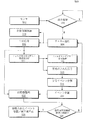
図5は本発明の実施形態に係り、入力信号を処理するための例示的なフローチャートである。図5を参照すれば、フローチャート500は本例示的なシステムによる信号分割及び基準点検出処理を説明する。処理される信号は、例えば図1に示された使用者着用型装置100のような着用型装置から受信される。使用者着用型装置100はセンサモジュール120を通じて生体信号を検出する。
FIG. 5 is an exemplary flow chart for processing an input signal according to an embodiment of the present invention. Referring to FIG. 5, a
段階502で、1つ以上のセンサが存在すれば、本例示的なシステムは生体信号モニタリングのためのセンサを選択する。選択されるセンサは、色々な判断基準の中でも例えば、信号の鮮明度、望む生体信号のタイプ、生体信号をモニタリングするのに必要である電力、などの基準に依存する。相異なる基準が他の実施形態に対しては使用され得る。相異なるセンサは相異なる信号タイプを提供するが、ここで信号タイプは一般的に、“クリーン(clean)”信号を提供する第1信号タイプ及び“雑音信号”を提供する第2信号タイプとして列挙される。“雑音信号”は、その後の処理に先立って、望ましくない信号成分を除去するために前処理(pre−process)される必要がある。例えば、ECG及びPPG信号は第1信号タイプ(“クリーン”信号)と称され、BCGは第2信号タイプ(“雑音信号”)と称される。これは段階512と関連してさらに説明される。
In
段階504で、センサモジュール120上の加速度計のようなセンサは使用者の動き(motion)をモニタリング/検出する。一部の生体信号は使用者の動きによって影響を受けないが、他のモニタリングされた生体信号は使用者が実質的に停止状態である時、さらに良い信号を提供する。例えば、BCG及びPPG信号は使用者が実質的に停止状態である時、より信頼性ある信号を提供する。従って、BCG又はPPG信号が要求される時、使用者の動きが所定の閾値レベル以上であれば、プロセスは段階504にループバックする。使用者の動きが所定の閾値レベルより低ければ、センサからの生体信号が処理のために受け入れられ、プロセスは段階506に進行する。段階504で使用者の動きをモニタリングすることは本開示の一部の実施形態に対して選択的であることを注意しなければならない。
At
段階506で、選択するべき多重チャネルがある実施形態で、本例示的なシステムは望ましい信号候補を決定するためにチャネルを選択する。例えば、加速度計及びジャイロメータのような測定センサがBCG信号を提供する場合、チャネル候補は、加速度計の3つの軸の各々に対する出力、加速度計の大きさ、及び1つのチャネルを選択できる多数のチャネルに対するジャイロメータの多重出力を含む。しかし、本開示の多様な実施形態はこれに制限される必要はない。
一実施形態によれば、本例示的なシステムは信号品質向上の目的のために信号混合(signal fusion)のようにチャネルを結合して新しいチャネルを形成してチャネルの数を更に増加できる。本例示的なシステムは、例えば再現率(recurrence rate)分析、周波数スペクトルで優位(又は優勢な)周波数の決定、及びエントロピ分析の中で1つ以上に基づいてチャネルを選択する。例えば、BCGチャネル選択のためにスペクトル分析を使用する時、優勢な周波数成分のより高い電力比率は、測定された信号のより良い決定のみならず、アーティファクト(artifacts、人為的なゴミ・キズ)の抑制を呈する。また、多様な実施形態は、オプションとしてチャネル選択を有する。例えば、ただ1つのチャネル入力のみがある場合、チャネル選択は必要としない。
At
According to one embodiment, the exemplary system may further increase the number of channels by combining channels to form a new channel such as signal fusion for the purpose of improving signal quality. The exemplary system selects a channel based on one or more of, for example, recurrence rate analysis, determination of dominant (or dominant) frequencies in the frequency spectrum, and entropy analysis. For example, when using spectral analysis for BCG channel selection, a higher power ratio of the dominant frequency components results in a better determination of the measured signal as well as artifacts. Exhibit suppression. Also, various embodiments optionally have channel selection. For example, if there is only one channel input, then channel selection is not needed.
段階508で、本例示的なシステムはセンサの選択されたチャネルから生の信号(raw signal)を受信する。段階510で、本例示的なシステムはフレームワークの将来の再初期化の際に使用できるにメモリ210に、例えば身体の姿勢及び方向のような身体位置情報を格納する。
At step 508, the exemplary system receives a raw signal from the selected channel of the sensor. In
段階512で、本例示的なシステムは段階506においてチャネル選択プロセスが存在するか否かによって、(段階508で)選択されたチャネルからの、又は測定センサからの直接的な、生の信号を前処理(pre−process)する。例えば、本例示的なシステムは、時間−周波数(time−frequency)処理技術及び/又は時間−ドメイン(time−domain)処理技術のような技術を使用することによって、呼吸アーティファクト(artifacts)及び高周波攪乱(high frequency disturbances)を除去するためにBCG信号を前処理する。時間−周波数処理技術は特に、ウェーブレット係数再構成(wavelet coefficient reconstruction)を含み、時間−ドメイン処理技術は特に、帯域通過フィルタリングを含む。
At step 512, the exemplary system pre-processes the raw signal from the selected channel (at step 508) or directly from the measurement sensor, depending on whether there is a channel selection process at
一実施形態は、例えば実質的に0.5−3.5Hzの望ましい通過周波数帯域を有する帯域通過フィルタを使用して生のBCG信号をフィルタリングする。帯域通過フィルタリングは図2に示された帯域通過フィルタ270を通じるか、例えば、プロセッサ112又はCPU200のような1つ以上の診断プロセッサを使用するデジタル信号処理を通じて遂行される。使用者からの信号が比較的にクリーン信号であると判別されれば、段階512での前処理は選択的である。
従って、センサのタイプは、また前処理が必要であるか否かを決定するのに使用される。例えば、ECGセンサ又はPPGセンサからの信号は前処理される必要がない。他の実施形態は、使用されるセンサに関わらず、信号が前処理される必要がない程度に十分にクリーンであるか否かを決定する。同様に多様な実施形態は、通常はクリーン信号を生成するセンサが使用される場合にも信号が前処理される必要があることを決定できる。
One embodiment filters the raw BCG signal using a bandpass filter having a desired pass frequency band of, for example, substantially 0.5-3.5 Hz. Bandpass filtering is accomplished through the
Therefore, the type of sensor is also used to determine if pretreatment is necessary. For example, signals from ECG or PPG sensors need not be preprocessed. Other embodiments, regardless of the sensor used, determine if the signal is clean enough that it does not need to be pre-processed. Similarly, various embodiments can determine that the signal also needs to be preprocessed if a sensor that normally produces a clean signal is used.
段階514で、本例示的なシステムは例えば、帯域通過フィルタリングされた信号のように前処理された信号を発生する。他の実施形態で、本例示的なシステムは生のBCG信号を周波数帯域に分解する。例えば、BCG信号は5レベルのドビシ・ウェーブレット(Daubechies5 wavelet)を使用して100Hzのサンプリングレートで分解される。第2周波数帯域乃至第5周波数帯域からのウェーブレット係数は大部分の心臓拍動情報を担うと考慮される。超低周波(very low frequency、VLF)帯域は呼吸信号であると看做される。マザー(mother)ウェーブレット及び分解設定(例えば、分解レベルの数)は本開示の範囲を逸脱せずに、類似の結果を達成するように調整できることに留意しなければならない。
At
本例示的なシステムは以後、エネルギエントロピを分解された信号周波数帯域に適用することによって分解されたBCG信号を再構成するためにウェーブレット係数の再構成を利用する。再構成されたBCG信号は高調波成分及びアーティファクト曖昧性が無いという向上された基本反複パターンを有する。再構成されたBCG信号は段階514で前処理された信号として示される。本実施形態では分解されたBCG信号を再構成するためにエネルギエントロピを使用するが、本開示の多様な実施形態は必ずしもこのように制限されない。また、分解されたBCG信号を再構成するために他の技術が使用できる。
The exemplary system thereafter utilizes wavelet coefficient reconstruction to reconstruct the decomposed BCG signal by applying energy entropy to the decomposed signal frequency band. The reconstructed BCG signal has an improved fundamental decompounding pattern with no harmonic content and no artifact ambiguity. The reconstructed BCG signal is shown as the preprocessed signal in
2016年5月31日付に出願された特許文献2、 “Method and Apparatus for Heart Rate and Respiration Rate Estimation Using Low Power Sensor”は、BCG信号を多数の周波数帯域に分解し、BCG信号を再構成するシステム及び方法を開示し、本明細書において参照により統合される。 Patent Document 2 filed on May 31, 2016, "Method and Apparatus for Heart Rate and Respiration Rate Estimating Using Low Power Sensor" decomposes a BCG signal into a number of frequency bands to reconstruct a BCG signal. And methods are disclosed and incorporated herein by reference.
段階516で、本例示的なシステムはフィルタリングアウトされた(filtered−out)周波数成分を段階512から受信し、例えば、以後の分析のためにフィルタリングアウトされた周波数成分をメモリ210に格納する。本例示的なシステムは別途、フィルタリングアウトされた低周波成分を分析して、例えば呼吸数のみならず、吸い込む息及び吐き出す息の開始を推定する。フィルタリングアウトされた高周波成分は、別途、例えば生体認識のために使用される。
At
段階518で、本例示的なシステムは、例えば時間遅延挿入(time delay embedding、TDE)ビート検出に基づいて、信号イベント分割(signal event segmentation)のために前処理された信号をさらに処理する。TDE接近法(アプローチ)は与えられた信号の多様な形態学的(morphological)変化に対して安定で崩れにくいな(robust)ビート位置(beat locations)を低い計算費用で以って生成できる。TDEアプローチはサンプル地点を遅延された地点に対してプロッティングする(plotting)ことによって信号を2次元空間にマッピングする。適応形閾値(adaptive_thresholding)ビート検出がまた信号イベント分割に対して使用できる。これは図6A乃至図8を参照してさらに説明される。 At step 518, the exemplary system further processes the preprocessed signal for signal event segmentation, eg, based on time delay embedding (TDE) beat detection. The TDE approach can generate stable, robust beat locations for various morphological changes of a given signal with low computational cost. The TDE approach maps the signal to a two-dimensional space by plotting the sample points to the delayed points. Adaptive thresholding beat detection can also be used for signal event splitting. This is further explained with reference to FIGS. 6A-8.
段階520で、本例示的なシステムはイベント位置に対して分割された信号を処理し、実時間特徴の整列は(段階508からの)生の信号を使用して段階522で遂行する。段階518から段階522までの処理は2015年10月30日に出願された上記特許文献1、“Method for Low−Power−Consumption、Robust Estimation of Cardiovascular Periodicity、Contour Analysis、and Heart Rate”により詳細に開示されている。本出願は時間遅延基盤ビート検出のためのシステム及び方法を説明し、本明細書において参照により統合される。
At
例えば、相関方法(correlation method)及び/又は動的時間ワーピング(dynamic time warping、DTW)方法のような、実時間特徴整列(real_time_feature_alignment)のために多様な類似性マッチング技術(similarity matching techniques)が使用できる。例えば、DTWは、2つの連続してクリップされたセグメント(clipped segments)の時間的類似性パターンをマッチングする(match)のに使用される。DTW距離は与えられた2つのシークェンスの間の最適のマッチングを決定するための類似性の指標(indicator)を提供する。 For example, various similarity matching techniques may be used for real_time_feature_alignment, such as a correlation method and/or a dynamic time warping (DTW) method. it can. For example, DTW is used to match the temporal similarity pattern of two consecutive clipped segments. The DTW distance provides a similarity indicator for determining the best match between two given sequences.
一実施形態によれば、確率関数はDTW方法に適用されてセグメントの中心付近に近い主な特徴地点により大きい加重値を割当し、ノイズとして解釈されるエッジ地点に、より小さい加重値を割当する。これにより整列性能の信頼度び精度は、さらに向上できる。これは後に図9に示される。確率関数はソフトマックス(softmax)関数、エントロピ、及びモジュラス(modulus)距離を含むが、これに限定されない。 According to one embodiment, a probability function is applied to the DTW method to assign higher weights to major feature points near the center of the segment and lower weights to edge points that are interpreted as noise. .. As a result, the reliability and accuracy of the alignment performance can be further improved. This is shown later in FIG. Stochastic functions include, but are not limited to, the softmax function, entropy, and modulus distance.
段階524で、本例示的なシステムは段階522の実時間特徴整列からの出力を使用して信号品質信頼度の指標を決定する。DTWからの整列レベルは信号品質の信頼度の指標として使用される。例えば、整列レベルは、整列された信号を生成するために整列された2つの事前整列された(pre−aligned)信号のより短いセグメントの長さに対する前記整列された信号の長さの比率である。さらに高い整列レベルは2つの連続的なセグメントがより高い類似性を有することを示す反面、より低い整列レベルは信号がより大きい形態学的変動を有することを示す。
信号品質信頼度の指標が所定の閾値より低ければ、プロセスはチャネル選択のために段階506に進行し、段階510で再初期化をもたらす。
At
If the signal quality confidence indicator is below a predetermined threshold, the process proceeds to step 506 for channel selection, resulting in re-initialization at
段階526で、例えば、睡眠診断(sleeping diagnosis)、血圧診断、心拍変動(heart rate variability、HRV)診断、呼吸数変化(respiration rate variability、RRV)診断、不整脈識別/無呼吸、及び動き認識において、心拍(パルス)速度、脈拍形態(波形)、脈拍間隔(ビート間間隔)、呼吸(息)数、及び血圧などの測定に際して使用するために本例示的なシステムは、(段階508からの)生の信号から精製されたイベント位置/基準点、及び/又は、(段階522からの)実時間特徴整列出力を生成する。
In
一実施形態は以上、図5に示されたフローチャートを用いて説明されたが、多様な実施形態は他のフローを示し、機能を追加し、又は機能を除去する他のプロセスを使用できると理解されなければならない。例えば、多様な実施形態は、段階502でセンサから受信された信号のタイプに従って段階522で整列を選択的に遂行する。段階502で受信された信号が、例えばPPG又はECGセンサを経由する場合、特徴の整列のための必要性が無い場合もある。従って、セグメント(segment)に対するイベント位置は他のセグメントとは独立的に決定され、このイベントはそのセグメントに対する基準点である。しかし、段階502で受信された信号が、例えばBCGセンサを経由する場合、各セグメントに対する基準点を決定する際に説明されたように、段階522で特徴整列が遂行される。何れの場合にも、出力信号は決定された基準点から生成される。
Although one embodiment has been described above using the flowchart shown in FIG. 5, it is understood that various embodiments may show other flows and use other processes for adding or removing functions. It must be. For example, various embodiments selectively perform alignment in
本発明の多様な実施形態は、イベント位置及び/又は基準点を決定するために、例えば極小(local minima)又は極大(local maxima)を使用する。 Various embodiments of the present invention use, for example, local minima or local maxima to determine event locations and/or reference points.
図6A乃至図6Eは本発明の一実施形態に係り、分割された多様なプロット(plots)の例を図示する。図4A乃至図4Eに示された信号プロットに各々対応する図6A乃至図6Eを参照すれば、信号プロットの各々は破線で表示されたように分割されている(segmented)。分割(segmentation)は、例えば図5の段階518で処理されたプロセスの結果である。 6A through 6E illustrate an example of various divided plots according to an exemplary embodiment of the present invention. Referring to FIGS. 6A-6E, which respectively correspond to the signal plots shown in FIGS. 4A-4E, each of the signal plots is segmented as indicated by the dashed line. The segmentation is a result of the process processed in step 518 of FIG. 5, for example.
図6A乃至図6Cは多様な信号ソースに対してTDEビート検出を使用する信号分割結果のBCG波形である。図6DはTDEビート検出を使用する信号分割結果を有するECG波形である。図6EはTDEビート検出を使用する信号分割結果を有するPPG波形である。他の実施形態で、信号イベント分割(例えば、BCG信号に対する)は適応形閾値(adaptive_thresholding)ビート検出アプローチを使用することによって遂行される。この信号は後続段階のためにTDEビート位置(図6A乃至図6Eの破線で示される)を使用してセグメントにさらにクリップ(clip)されてもよい。 6A to 6C are BCG waveforms resulting from signal division using TDE beat detection for various signal sources. FIG. 6D is an ECG waveform with a signal splitting result using TDE beat detection. FIG. 6E is a PPG waveform with a signal split result using TDE beat detection. In another embodiment, signal event splitting (eg, for BCG signals) is accomplished by using an adaptive thresholding beat detection approach. This signal may be further clipped to a segment using the TDE beat position (shown in dashed lines in FIGS. 6A-6E) for subsequent stages.
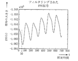
図7は一実施形態に係るフィルタリングされたPPG信号の例示的な波形を図示する。ここでx軸、y軸には各々、相対時間t、信号の大きさ(相対値)PPG(t)が割当てられる。フィルタリングされたPPG信号PPG(t)は、例えば図5の段階514のプロセスの結果である。
FIG. 7 illustrates an exemplary waveform of a filtered PPG signal according to one embodiment. Here, the relative time t and the signal magnitude (relative value) PPG(t) are assigned to the x-axis and the y-axis, respectively. The filtered PPG signal PPG(t) is the result of the process of
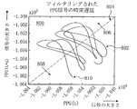
図8は一実施形態に係るフィルタリングされたPPG信号の時間遅延プロットの例示的な波形を図示する。判定ライン(decision line)804(図8で破線の対角線で表示される)は交差点を識別するために使用される。交差点は図6の破線で図示されたTDE分割位置(イベント位置)である。 FIG. 8 illustrates an exemplary waveform of a time delay plot of a filtered PPG signal according to one embodiment. A decision line 804 (shown as a dashed diagonal line in FIG. 8) is used to identify the intersection. The intersection is the TDE division position (event position) shown by the broken line in FIG.
図8は一実施形態に係る観測データの時系列(time−series)に対応する位相軌跡(phase trajectory)の例示的な2次元再構成のグラフを図示する。例示的なトレース(trace)800は2次元再構成の幾つかのサイクルを図示する。x軸及びy軸に対するベクトル802の軌跡は、45°角度で座標空間原点(0、0)を通過する判定ライン804(又は光線)との交差点に対して評価される。ベクトル802は判定ライン804に沿って幾つの点で所望の判定ライン804と交差する。矢印806、808は軌道(orbit)の方向を示す。ベクトル(802)が特定の方向(例えば、図8の左側から右側へ)で判定ライン804と交差する時点の各々はサイクル(cycle)又は周期(period)の開始を示す。2次元再構成のために、所望の判定ラインは1次元である。
FIG. 8 illustrates a graph of an exemplary two-dimensional reconstruction of a phase trajectory corresponding to time-series of observation data according to one embodiment. An
一例として、図7で、相対時間t=0での大きさは−1.056x10⁵であり、相対時間t=50での大きさは−1.062x10⁵である。以下、簡単にするために指数部を省略すると、t=0での信号の大きさ(相対値)PPG(0)は−1.056であり、相対時間t=50での信号の大きさは−1.062である。これが図8にマッピングされる。ここで、トレース800の終点にある点810は座標(−1.056、−1.062)を有する。図8のトレース800は時間tにおけるPPG信号の大きさPPG(t)をx座標として使用し、遅延された時間(t+d)でPPG信号の大きさPPG(t+d)をY座標として使用してプロット(plot)される。ここで、相対遅延dはこの例では50である。
As an example, in FIG. 7, the magnitude at relative time t=0 is −1.056×10 5 , and the magnitude at relative time t=50 is −1.062×10 5 . Hereinafter, if the exponent part is omitted for simplicity, the signal magnitude (relative value) PPG(0) at t=0 is −1.056, and the signal magnitude at the relative time t=50 is It is -1.062. This is mapped in FIG. Here, the
図9は二変量ガウシアン(bi−variate Gaussian)基盤のDTW輪郭(contour)に対する例示的なダイヤグラムを図示する。二変量分布がDTW行列(matrix)に適用されている。図9には比較するべき2つのセグメント902、912が図示されている。ガウシアン曲線904、914は、比較のためにより重く加重されるべきセグメント902、912の部分を各々示す。図示されたように、中心部分がより重く加重され、端部がより軽く加重される。二変量ガウシアン輪郭920は2つのセグメント902、912に対して注目するべき領域を示す。
FIG. 9 illustrates an exemplary diagram for a bivariate Gaussian based DTW contour. A bivariate distribution has been applied to the DTW matrix. Two
図10A及び図10Bは一実施形態に係るBCG分割マッチング結果の例示的な波形を図示する。 10A and 10B illustrate exemplary waveforms of BCG split matching results according to one embodiment.
図10Aは本発明の実施形態に係るBCG波形に対する時点別マッチングを示す例示図である。図10Aは、本発明のDTW方法を使用した、2つの連続的なBCGセグメントに対するDTWグラフィック性能の一例を提示するものであり、重要な特徴、特に(心臓)収縮波形がペア毎に正確に識別され、エッジ残余セクション(edging residual sections)が不一致を示す。図10Aにはセグメント1及びセグメント2が図示され、セグメント1及びセグメント2の多様な点は互いにマッチングされる。1つのセグメントの1つの点は他のセグメントの複数の点とマッチングされる。例えば、セグメント1上の点1000はセグメント2上の点1000a、1000bとマッチングされる。多様な実施形態は複数のマッチング点の中で1つを選択する異なる方法を有するが、最も近い点を維持する方法が使用できる。従って、セグメント1上の点1000に対して、セグメント2上の点1000bはマッチング点として維持される。同様に、セグメント2上の点1002はセグメント1上の点1002aとマッチングされる。選択されなかった点は残余点であると称され、廃棄される。
FIG. 10A is an exemplary diagram illustrating time-based matching for a BCG waveform according to an exemplary embodiment of the present invention. FIG. 10A presents an example of DTW graphic performance for two consecutive BCG segments using the DTW method of the present invention, where important features, particularly (cardiac) contraction waveforms, are accurately identified pair by pair. The edge residual sections indicate a mismatch. In FIG. 10A,
図10Bは本発明の一実施形態に係り、残余点が除去された状態におけるBCGマッチング比較を示した例示図である。図10Bはセグメント1及びセグメント2に対する残余点除去とBCGマッチング比較を示している。2つのセグメントは残余点を除去することによって同一の長さに切断(truncated)される。多様な実施形態は、例えば心臓拍動不整脈検出、心拍数変動、及び血圧計算のようなアプリケーションのためのビート(beat、拍動)別のマッチング結果を使用できる。
FIG. 10B is an exemplary diagram showing BCG matching comparison in a state in which residual points are removed according to an embodiment of the present invention. FIG. 10B shows residual point removal and BCG matching comparison for
図11A乃至図11Eは本発明の一実施形態に係る多様なプロットの特徴点を*印を付けて図示する。また、図11A乃至図11CはBCG信号に対する特徴点を図示し、図11DはECG信号の特徴点を図示し、図11EはPPG信号に対する特徴点を図示する。初期化又はリセットの後に第1番目のセグメントに対する極大エネルギの点を発見することによって特徴点(例えば、BCG信号からのJピーク又はIピーク、ECG信号からのRピーク、及びPPG信号上の1次ピーク(primary peaks)が決定される。後続のセグメントに対する対応する特徴点は本DTW方法を使用して識別される。 11A through 11E illustrate characteristic points of various plots with an asterisk (*) according to an exemplary embodiment of the present invention. 11A to 11C show characteristic points for the BCG signal, FIG. 11D shows characteristic points for the ECG signal, and FIG. 11E shows characteristic points for the PPG signal. Feature points (eg, J-peak or I-peak from BCG signal, R-peak from ECG signal, and first-order on PPG signal) by finding the point of maximum energy for the first segment after initialization or reset. The primary peaks are determined and the corresponding minutiae for subsequent segments are identified using the present DTW method.
一実施形態によれば、他の基準点が、初期化又はリセットの後に第1番目のセグメントに対して同様に選択される。後続のセグメントの基準点は以後に反復的に識別される。例えば、PPG上の一次低部(primary foot)が第1番目のイベントの特徴点として選択された場合、本フレームワークは後続のPPGセグメントで対応する一次ピークを識別することができる。 According to one embodiment, other reference points are likewise selected for the first segment after initialization or reset. The fiducial points of the subsequent segments are subsequently iteratively identified. For example, if a primary foot on the PPG is selected as the minutiae for the first event, the framework can identify the corresponding primary peak in subsequent PPG segments.
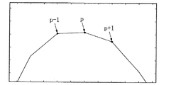
図12は本発明の一実施形態に係るビート位置補間のための例示的な波形である。センササンプリング速度の制限のため、ビート検出精密度は、図12に図示されたように、1/Fsスケールである。ここで、Fsはサンプリング周波数である。一実施形態によれば、本例示的なシステムは元のサンプリング速度以上にビート位置の解像度を増加させる補間法をさらに提供する。 FIG. 12 is an exemplary waveform for beat position interpolation according to an embodiment of the present invention. Due to the limitation of the sensor sampling rate, the beat detection accuracy is on the 1/Fs scale, as illustrated in FIG. Here, Fs is a sampling frequency. According to one embodiment, the exemplary system further provides an interpolation method that increases the resolution of the beat position over the original sampling rate.
一実施形態で、より正確なビート振幅及び位置(シフト比率)は次の数学式から導出される。

一実施形態によれば、ビート及び基準点検出はイネーブルストリームがトリガーされる時に、初期化される。例えば、ビート情報は図5の動き検出と関連して説明されたように、使用者の活動レベルが予め設定された閾値より低い時に連続的に計算される。 According to one embodiment, beat and reference point detection is initialized when the enable stream is triggered. For example, beat information is continuously calculated when the user's activity level is below a preset threshold, as described in connection with the motion detection of FIG.
使用者の活動レベルが予め設定された閾値を超過すれば、本例示的なシステムはリセットフラッグに基づいてビート及び基準点検出をリセットする。一実施形態によれば、着用型装置アプリケーションで、本例示的なシステムはリセットフラッグと共に位置/方位推定を記録する。位置推定は特に睡眠データに対して測定された対象の価値あるジェスチャ情報を提供する。 If the user's activity level exceeds a preset threshold, the exemplary system resets the beat and reference point detection based on the reset flag. According to one embodiment, in a wearable device application, the exemplary system records a position/orientation estimate with a reset flag. Position estimation provides valuable gesture information of an object measured against sleep data in particular.
一実施形態によれば、本例示的なシステムは睡眠段階、心拍変動(HRV)診断及び睡眠姿勢診断などの他の診断アプリケーションのために位置情報をビート及び基準位置と結合できる。 According to one embodiment, the exemplary system can combine location information with beats and reference locations for other diagnostic applications such as sleep stage, heart rate variability (HRV) diagnostics and sleep posture diagnostics.
多様な実施形態はBCG、ECG及びPPG信号を処理することを説明した。しかし、本開示の多様な実施形態は他の生体信号にもまた適用できる。 Various embodiments have been described for processing BCG, ECG and PPG signals. However, the various embodiments of the present disclosure are also applicable to other vital signs.
本発明の多様な実施形態はコンピュータプログラムとして書き込まれ、非一時的コンピュータ読出し可能記録媒体を使用してプログラムを実行する汎用デジタルコンピュータで具現される。 Various embodiments of the present invention are embodied in a general purpose digital computer written as a computer program and using a non-transitory computer readable recording medium to execute the program.
非一時的なコンピュータ読出し可能記録媒体は、例えばマグネチック格納媒体(例えば、磁気カード、フロッピディスク、ハードディスク)及び光記録媒体(例えば、CD−ROM、DVD)を含む。 Non-transitory computer readable recording media include, for example, magnetic storage media (eg, magnetic cards, floppy disks, hard disks) and optical recording media (eg, CD-ROM, DVD).
本明細書の多様な実施形態が図面を参照して説明されたが、当業者は以下の請求の範囲に定義されたように、本開示の思想及び範囲を逸脱せずに、形態及び細部事項に関して多様な変化を為し得ると理解すべきである。従って、前記実施形態及びその全ての態様は単なる例示であり、制限的ではない。 While various embodiments of the present specification have been described with reference to the drawings, those of ordinary skill in the art may define the form and details as defined in the following claims without departing from the spirit and scope of the present disclosure. It should be understood that various changes can be made regarding. Accordingly, the above embodiments and all aspects thereof are merely illustrative and not limiting.
100 使用者着用型装置
102 ディスプレイ
110、112 プロセッサ
120 センサモジュール
122、124 センサ
130 バッテリ
140 バンド
142 クラスプ
200 CPU
210 メモリ
212 オペレーティングシステム(OS)
214 アプリケーション
216 不揮発性メモリ
218 揮発性メモリ
220 IOインタフェイス
230 通信インタフェイス
240 電源管理ユニット(PMU)
250 分解モジュール
260 再構成モジュール
270 帯域通過フィルタ
300 スマートフォン
302 通信信号
BCG 心弾動図(ballistocardiography)
DTW 適応式動的時間ワ−プ(adaptive dynamic time warping)
ECG 心電図(electrocardiogram)
GSR 電気皮膚反応(galvanic skin response)
HRV 心拍変動(heart rate variability)
PPG 光電式容積脈波図(photoplethysmogram)
RRV 呼吸数変動(respiration rate variability)
TDE 時間遅延挿入(time−delay embedding)
100 user
210
214
250
DTW adaptive dynamic time warping
ECG electrocardiogram
GSR galvanic skin response
HRV heart rate variability
PPG Photoplethysmogram
RRV Respiration rate variability
TDE time-delay embedding
Claims (24)
前記使用者の動きをモニタリングする段階と、有し、
前記モニタリングする段階で、前記モニタリングされた動きが予め設定された閾値よりも低い場合、
前記第1信号から第2信号を提供する段階と、
前記第2信号を分割して第1信号セグメント及び第2信号セグメントを形成する段階と、
前記信号タイプに基づいて、前記第1信号セグメント及び前記第2信号セグメントを処理し、前記第1信号セグメント及び前記第2信号セグメントの各々に対する基準点を決定する段階と、を含み、
前記基準点を決定する段階は、
前記信号タイプがBCG(ballistocardiography)信号であると決定された場合、
前記第1信号セグメントから第1イベント位置を決定し、前記第1信号セグメントに対する前記基準点として前記第1イベント位置を識別する段階と、
前記第2信号セグメントから1つ以上の隣接点を前記第1信号セグメントに対する前記基準点にマッチングさせる段階と、
前記1つ以上の隣接点の中の1つを前記第1信号セグメントに対する前記基準点に対応する前記第2信号セグメントに対する基準点として選択し、前記基準点を利用して第3信号を生成する段階と、
を含むことを特徴とする方法。 Determining a signal type for the first signal received through at least one channel from use for persons,
Monitoring the movement of the user, and
In the step of monitoring, if the monitored movement is lower than a preset threshold,
Providing a second signal from the first signal;
Splitting the second signal to form a first signal segment and a second signal segment;
Based on said signal type, and processing the first signal segment and the second signal segment includes the steps of determining a reference point for each of the first signal segment and the second signal segment,
Determining the reference point,
If the previous SL signal type is determined to be BCG (ballistocardiography) signal,
Determining a first event position from the first signal segment and identifying the first event position as the reference point for the first signal segment;
Matching one or more adjacent points from the second signal segment to the reference point for the first signal segment;
The one or more selected as the base reference point against the second signal segment corresponding to the reference point with respect to the first signal segment with one of the adjacent points, the third signal using the reference point To generate
A method comprising:
前記少なくとも1つのチャネルの中の任意のチャネルは、前記新しいチャネルであることを特徴とする請求項1に記載の方法。 A low the third signal than a preset threshold, further comprising the step of selecting a new channel for receiving said first signal from said user,
Wherein any channels in the at least one channel, the method according to claim 1, wherein the new channel.
診断プロセッサと、を含み、
前記少なくとも1つのセンサは、少なくとも1つのチャネルを有し、前記第1信号は、前記少なくとも1つのチャネルの中の1つのチャネルから受信され、そして、前記少なくとも1つのセンサの中の少なくとも1つは、使用者の動きをモニタリングするように構成され、
前記診断プロセッサは、
前記モニタリングされた動きが予め設定された閾値よりも低い場合、
前記第1信号の信号タイプを決定し、
前記第1信号から第2信号を提供し、
前記第2信号を分割して第1信号セグメント及び第2信号セグメントを形成し、
前記信号タイプに基づいて、前記第1信号セグメント及び前記第2信号セグメントを処理し、前記第1信号セグメント及び前記第2信号セグメントの各々に対する基準点を決定し、
前記第1信号がBCG(ballistocardiography)信号であると決定された場合、前記診断プロセッサは、
前記第1信号セグメントから第1イベント位置を決定し、前記第1信号セグメントに対する前記基準点として前記第1イベント位置を識別し、
前記第2信号セグメントから1つ以上の隣接点を前記第1信号セグメントに対する前記基準点にマッチングさせ、
前記1つ以上の隣接点の中の1つを前記第1信号セグメントに対する前記基準点に対応する前記第2信号セグメントに対する基準点として選択し、前記基準点を利用して第3信号を生成することを特徴とするシステム。 At least one sensor configured from use for users to acquire the first signal,
A diagnostic processor, and
The at least one sensor has at least one channel, the first signal is received from one of the at least one channel, and at least one of the at least one sensor has Configured to monitor user movement,
The diagnostic processor is
If the monitored movement is below a preset threshold,
Determining the signal type of the first signal,
Providing a second signal from the first signal,
Dividing the second signal to form a first signal segment and a second signal segment,
Processing the first signal segment and the second signal segment based on the signal type and determining a reference point for each of the first signal segment and the second signal segment ;
If the previous Symbol first signal is determined to be BCG (ballistocardiography) signal, the diagnostic processor,
Determining a first event position from the first signal segment and identifying the first event position as the reference point for the first signal segment;
Matching one or more adjacent points from the second signal segment to the reference point for the first signal segment,
The one or more selected as the base reference point against the second signal segment corresponding to the reference point with respect to the first signal segment with one of the adjacent points, the third signal using the reference point A system characterized by generating .
Applications Claiming Priority (4)
| Application Number | Priority Date | Filing Date | Title |
|---|---|---|---|
| US201662356164P | 2016-06-29 | 2016-06-29 | |
| US62/356,164 | 2016-06-29 | ||
| US15/264,333 US10426411B2 (en) | 2016-06-29 | 2016-09-13 | System and method for providing a real-time signal segmentation and fiducial points alignment framework |
| US15/264,333 | 2016-09-13 |
Publications (3)
| Publication Number | Publication Date |
|---|---|
| JP2018000952A JP2018000952A (en) | 2018-01-11 |
| JP2018000952A5 JP2018000952A5 (en) | 2020-07-27 |
| JP6745762B2 true JP6745762B2 (en) | 2020-08-26 |
Family
ID=60662241
Family Applications (1)
| Application Number | Title | Priority Date | Filing Date |
|---|---|---|---|
| JP2017117509A Active JP6745762B2 (en) | 2016-06-29 | 2017-06-15 | System and method for providing real-time signal partitioning and fiducial alignment framework |
Country Status (6)
| Country | Link |
|---|---|
| US (1) | US10426411B2 (en) |
| JP (1) | JP6745762B2 (en) |
| KR (1) | KR20180002524A (en) |
| CN (1) | CN107536599A (en) |
| DE (1) | DE102017112819A1 (en) |
| TW (1) | TWI720215B (en) |
Families Citing this family (38)
| Publication number | Priority date | Publication date | Assignee | Title |
|---|---|---|---|---|
| US12080421B2 (en) | 2013-12-04 | 2024-09-03 | Apple Inc. | Wellness aggregator |
| US20160019360A1 (en) | 2013-12-04 | 2016-01-21 | Apple Inc. | Wellness aggregator |
| CN109599161B (en) | 2014-09-02 | 2023-09-29 | 苹果公司 | Physical activity and fitness monitor |
| CN113521710A (en) | 2015-08-20 | 2021-10-22 | 苹果公司 | Motion-based dial and complex function block |
| AU2017100667A4 (en) | 2016-06-11 | 2017-07-06 | Apple Inc. | Activity and workout updates |
| US11216119B2 (en) | 2016-06-12 | 2022-01-04 | Apple Inc. | Displaying a predetermined view of an application |
| US10736543B2 (en) | 2016-09-22 | 2020-08-11 | Apple Inc. | Workout monitor interface |
| US10617364B2 (en) * | 2016-10-27 | 2020-04-14 | Samsung Electronics Co., Ltd. | System and method for snoring detection using low power motion sensor |
| US10845955B2 (en) * | 2017-05-15 | 2020-11-24 | Apple Inc. | Displaying a scrollable list of affordances associated with physical activities |
| SG10201800954QA (en) * | 2018-02-02 | 2019-09-27 | Nec Asia Pacific Pte Ltd | Method and system for signal processing rehabilitation exercise signals |
| US11294464B2 (en) * | 2018-02-22 | 2022-04-05 | TRIPP, Inc. | Adapting media content to a sensed state of a user |
| DK201870599A1 (en) | 2018-03-12 | 2019-10-16 | Apple Inc. | User interfaces for health monitoring |
| US10849531B2 (en) * | 2018-04-17 | 2020-12-01 | Samsung Electronics Co., Ltd. | Systematic apparatus for motion sensor and optical sensor based cardiac arrhythmia triage |
| DK201870380A1 (en) | 2018-05-07 | 2020-01-29 | Apple Inc. | Displaying user interfaces associated with physical activities |
| US11317833B2 (en) | 2018-05-07 | 2022-05-03 | Apple Inc. | Displaying user interfaces associated with physical activities |
| FI20185441A1 (en) * | 2018-05-14 | 2019-11-15 | Pulseon Oy | A method, an apparatus and a computer program product for estimating the quality of a signal |
| US10953307B2 (en) | 2018-09-28 | 2021-03-23 | Apple Inc. | Swim tracking and notifications for wearable devices |
| US11857309B2 (en) * | 2019-02-07 | 2024-01-02 | Casey Marie Campbell | Respiration monitoring device and methods for use |
| DK201970532A1 (en) | 2019-05-06 | 2021-05-03 | Apple Inc | Activity trends and workouts |
| DK201970534A1 (en) | 2019-06-01 | 2021-02-16 | Apple Inc | User interfaces for monitoring noise exposure levels |
| US11209957B2 (en) | 2019-06-01 | 2021-12-28 | Apple Inc. | User interfaces for cycle tracking |
| US11152100B2 (en) | 2019-06-01 | 2021-10-19 | Apple Inc. | Health application user interfaces |
| AU2020288139B2 (en) | 2019-06-01 | 2023-02-16 | Apple Inc. | Multi-modal activity tracking user interface |
| US11234077B2 (en) | 2019-06-01 | 2022-01-25 | Apple Inc. | User interfaces for managing audio exposure |
| US11228835B2 (en) | 2019-06-01 | 2022-01-18 | Apple Inc. | User interfaces for managing audio exposure |
| US12002588B2 (en) | 2019-07-17 | 2024-06-04 | Apple Inc. | Health event logging and coaching user interfaces |
| EP4004702A1 (en) | 2019-09-09 | 2022-06-01 | Apple Inc. | Research study user interfaces |
| DK202070616A1 (en) | 2020-02-14 | 2022-01-14 | Apple Inc | User interfaces for workout content |
| CN113491513B (en) * | 2020-04-08 | 2023-06-30 | 华为技术有限公司 | Heart rhythm detection control method and terminal |
| DK181037B1 (en) | 2020-06-02 | 2022-10-10 | Apple Inc | User interfaces for health applications |
| US11698710B2 (en) | 2020-08-31 | 2023-07-11 | Apple Inc. | User interfaces for logging user activities |
| US11697020B2 (en) | 2020-11-19 | 2023-07-11 | A-Neuron Electronic Corporation | Method for generating stimulation parameters, electrical stimulation control apparatus and electrical stimulation system |
| TWI819253B (en) * | 2020-11-25 | 2023-10-21 | 緯創資通股份有限公司 | Signal quality detection method and signal detection device thereof |
| WO2022245669A1 (en) | 2021-05-15 | 2022-11-24 | Apple Inc. | User interfaces for group workouts |
| US11977729B2 (en) | 2022-06-05 | 2024-05-07 | Apple Inc. | Physical activity information user interfaces |
| US12023567B2 (en) | 2022-06-05 | 2024-07-02 | Apple Inc. | User interfaces for physical activity information |
| CN114767127B (en) * | 2022-06-21 | 2022-09-30 | 广州中科新知科技有限公司 | Method and system for processing ballistocardiogram signal |
| CN117752326B (en) * | 2023-11-14 | 2024-07-19 | 武汉光谷航天三江激光产业技术研究院有限公司 | Cardiac state judging method based on recursive graph and waveform distribution of BCG signals |
Family Cites Families (16)
| Publication number | Priority date | Publication date | Assignee | Title |
|---|---|---|---|---|
| CN101416876A (en) * | 2007-10-24 | 2009-04-29 | 方识钦 | Identification device and method using cardiogram |
| US9443141B2 (en) | 2008-06-02 | 2016-09-13 | New York University | Method, system, and computer-accessible medium for classification of at least one ICTAL state |
| US8140330B2 (en) | 2008-06-13 | 2012-03-20 | Robert Bosch Gmbh | System and method for detecting repeated patterns in dialog systems |
| CN102088904B (en) * | 2008-07-11 | 2013-03-20 | 皇家飞利浦电子股份有限公司 | Ballistocardiogram analysis method and device |
| US8137283B2 (en) | 2008-08-22 | 2012-03-20 | International Business Machines Corporation | Method and apparatus for retrieval of similar heart sounds from a database |
| US8870780B2 (en) * | 2008-10-15 | 2014-10-28 | The Board Of Trustees Of The Leland Stanford Junior University | Systems and methods for monitoring heart function |
| US20120123232A1 (en) * | 2008-12-16 | 2012-05-17 | Kayvan Najarian | Method and apparatus for determining heart rate variability using wavelet transformation |
| EP2459065B1 (en) * | 2009-07-31 | 2014-01-08 | Koninklijke Philips N.V. | Method and apparatus for the analysis of a ballistocardiogram signal |
| WO2011140632A1 (en) | 2010-05-11 | 2011-11-17 | The Royal Institute For The Advancement Of Learning/Mcgill University | Method of identification and devices thereof |
| EP2672884A1 (en) * | 2011-02-09 | 2013-12-18 | Massachusetts Institute Of Technology | Ear wearable vital sign monitor |
| KR101316497B1 (en) * | 2012-08-03 | 2013-10-10 | 현대자동차주식회사 | System and method for observing heart rate of passenger |
| JP5724976B2 (en) * | 2012-09-20 | 2015-05-27 | カシオ計算機株式会社 | Exercise information detection apparatus, exercise information detection method, and exercise information detection program |
| US9396643B2 (en) * | 2013-10-23 | 2016-07-19 | Quanttus, Inc. | Biometric authentication |
| WO2016036114A1 (en) * | 2014-09-03 | 2016-03-10 | Samsung Electronics Co., Ltd. | Electronic device and method for measuring vital signal |
| CN104644160A (en) * | 2015-03-18 | 2015-05-27 | 电子科技大学 | Electrocardiogram pseudo-difference signal identification method and device |
| WO2016154256A1 (en) * | 2015-03-25 | 2016-09-29 | Quanttus, Inc. | Contact-less blood pressure measurement |
-
2016
- 2016-09-13 US US15/264,333 patent/US10426411B2/en active Active
-
2017
- 2017-06-12 DE DE102017112819.0A patent/DE102017112819A1/en not_active Withdrawn
- 2017-06-15 JP JP2017117509A patent/JP6745762B2/en active Active
- 2017-06-22 TW TW106120825A patent/TWI720215B/en not_active IP Right Cessation
- 2017-06-26 KR KR1020170080518A patent/KR20180002524A/en not_active Application Discontinuation
- 2017-06-29 CN CN201710513116.9A patent/CN107536599A/en active Pending
Also Published As
| Publication number | Publication date |
|---|---|
| US10426411B2 (en) | 2019-10-01 |
| TW201806370A (en) | 2018-02-16 |
| US20180000426A1 (en) | 2018-01-04 |
| CN107536599A (en) | 2018-01-05 |
| TWI720215B (en) | 2021-03-01 |
| DE102017112819A1 (en) | 2018-01-04 |
| KR20180002524A (en) | 2018-01-08 |
| JP2018000952A (en) | 2018-01-11 |
Similar Documents
| Publication | Publication Date | Title |
|---|---|---|
| JP6745762B2 (en) | System and method for providing real-time signal partitioning and fiducial alignment framework | |
| US10722182B2 (en) | Method and apparatus for heart rate and respiration rate estimation using low power sensor | |
| US10362997B2 (en) | System and method of extraction, identification, marking and display of heart valve signals | |
| US10441180B2 (en) | Episodical and continuous ECG monitoring | |
| US12048517B2 (en) | System and method for real-time heartbeat events detection using low-power motion sensor | |
| US11234658B2 (en) | Photoplethysmogram data analysis and presentation | |
| EP3403574A1 (en) | Device for reliable acquisition of photoplethysmographic data | |
| CN112165897A (en) | Photoplethysmogram data analysis and presentation | |
| US10368765B2 (en) | Wearable apparatus for ECG signal acquisition | |
| EP3048972A1 (en) | Processing apparatus, processing method and system for processing a physiological signal | |
| Tadi et al. | Comprehensive analysis of cardiogenic vibrations for automated detection of atrial fibrillation using smartphone mechanocardiograms | |
| KR20100128023A (en) | The emotion recognition system based on biometric signals | |
| JP2015211829A (en) | Determination of arterial pulse wave transit time from vpg and ecg/ekg signal | |
| Wrobel et al. | Pregnancy telemonitoring with smart control of algorithms for signal analysis | |
| CN111031902B (en) | Multi-sensor stroke output monitoring system and analysis method | |
| Al-Naji et al. | Remote measurement of cardiopulmonary signal using an unmanned aerial vehicle | |
| Sonawani et al. | Biomedical signal processing for health monitoring applications: a review | |
| EP3399905A1 (en) | System and method of extraction, identification, making and display of the heart valve signals | |
| Rashkovska et al. | Clustering of heartbeats from ECG recordings obtained with wireless body sensors | |
| JP7332723B2 (en) | System for detecting QRS complexes in an electrocardiogram (ECG) signal | |
| Kraft et al. | Reliability factor for accurate remote PPG systems | |
| Norouzi | Multi-modal heart-beat estimation on an iPhone | |
| Piazzo et al. | An Electrocardiogram (ECG) Signal Processing Algorithm for Heart Parameters Estimation based on QRS Complex Detection |
Legal Events
| Date | Code | Title | Description |
|---|---|---|---|
| A521 | Request for written amendment filed |
Free format text: JAPANESE INTERMEDIATE CODE: A523 Effective date: 20200612 |
|
| A621 | Written request for application examination |
Free format text: JAPANESE INTERMEDIATE CODE: A621 Effective date: 20200612 |
|
| A871 | Explanation of circumstances concerning accelerated examination |
Free format text: JAPANESE INTERMEDIATE CODE: A871 Effective date: 20200612 |
|
| A975 | Report on accelerated examination |
Free format text: JAPANESE INTERMEDIATE CODE: A971005 Effective date: 20200703 |
|
| TRDD | Decision of grant or rejection written | ||
| A01 | Written decision to grant a patent or to grant a registration (utility model) |
Free format text: JAPANESE INTERMEDIATE CODE: A01 Effective date: 20200707 |
|
| A61 | First payment of annual fees (during grant procedure) |
Free format text: JAPANESE INTERMEDIATE CODE: A61 Effective date: 20200804 |
|
| R150 | Certificate of patent or registration of utility model |
Ref document number: 6745762 Country of ref document: JP Free format text: JAPANESE INTERMEDIATE CODE: R150 |
|
| R250 | Receipt of annual fees |
Free format text: JAPANESE INTERMEDIATE CODE: R250 |
|
| R250 | Receipt of annual fees |
Free format text: JAPANESE INTERMEDIATE CODE: R250 |