JP6743390B2 - Drive transmission device and image forming apparatus - Google Patents
Drive transmission device and image forming apparatus Download PDFInfo
- Publication number
- JP6743390B2 JP6743390B2 JP2016006062A JP2016006062A JP6743390B2 JP 6743390 B2 JP6743390 B2 JP 6743390B2 JP 2016006062 A JP2016006062 A JP 2016006062A JP 2016006062 A JP2016006062 A JP 2016006062A JP 6743390 B2 JP6743390 B2 JP 6743390B2
- Authority
- JP
- Japan
- Prior art keywords
- transmission device
- drive transmission
- gear
- planetary gear
- shaft
- Prior art date
- Legal status (The legal status is an assumption and is not a legal conclusion. Google has not performed a legal analysis and makes no representation as to the accuracy of the status listed.)
- Active
Links
- 230000005540 biological transmission Effects 0.000 title claims description 56
- 239000000463 material Substances 0.000 claims description 15
- 230000002093 peripheral effect Effects 0.000 claims description 6
- 239000002184 metal Substances 0.000 claims description 4
- 229910052751 metal Inorganic materials 0.000 claims description 4
- 239000000314 lubricant Substances 0.000 claims description 3
- 229920005989 resin Polymers 0.000 claims description 2
- 239000011347 resin Substances 0.000 claims description 2
- 230000007246 mechanism Effects 0.000 description 29
- 238000004140 cleaning Methods 0.000 description 6
- 229920006324 polyoxymethylene Polymers 0.000 description 6
- 229920003002 synthetic resin Polymers 0.000 description 6
- 239000000057 synthetic resin Substances 0.000 description 6
- 239000003086 colorant Substances 0.000 description 4
- 238000010438 heat treatment Methods 0.000 description 4
- 229930182556 Polyacetal Natural products 0.000 description 3
- 229920000106 Liquid crystal polymer Polymers 0.000 description 2
- 239000004977 Liquid-crystal polymers (LCPs) Substances 0.000 description 2
- 239000004734 Polyphenylene sulfide Substances 0.000 description 2
- 239000004417 polycarbonate Substances 0.000 description 2
- 229920000139 polyethylene terephthalate Polymers 0.000 description 2
- 239000005020 polyethylene terephthalate Substances 0.000 description 2
- 229920000069 polyphenylene sulfide Polymers 0.000 description 2
- 229920000049 Carbon (fiber) Polymers 0.000 description 1
- 239000004952 Polyamide Substances 0.000 description 1
- 239000004917 carbon fiber Substances 0.000 description 1
- 239000003638 chemical reducing agent Substances 0.000 description 1
- 238000007599 discharging Methods 0.000 description 1
- 239000003365 glass fiber Substances 0.000 description 1
- 150000002739 metals Chemical class 0.000 description 1
- VNWKTOKETHGBQD-UHFFFAOYSA-N methane Chemical compound C VNWKTOKETHGBQD-UHFFFAOYSA-N 0.000 description 1
- 229920002647 polyamide Polymers 0.000 description 1
- 229920000515 polycarbonate Polymers 0.000 description 1
- -1 polyethylene terephthalate Polymers 0.000 description 1
- 239000002699 waste material Substances 0.000 description 1
Images

Classifications
-
- G—PHYSICS
- G03—PHOTOGRAPHY; CINEMATOGRAPHY; ANALOGOUS TECHNIQUES USING WAVES OTHER THAN OPTICAL WAVES; ELECTROGRAPHY; HOLOGRAPHY
- G03G—ELECTROGRAPHY; ELECTROPHOTOGRAPHY; MAGNETOGRAPHY
- G03G21/00—Arrangements not provided for by groups G03G13/00 - G03G19/00, e.g. cleaning, elimination of residual charge
- G03G21/16—Mechanical means for facilitating the maintenance of the apparatus, e.g. modular arrangements
- G03G21/1642—Mechanical means for facilitating the maintenance of the apparatus, e.g. modular arrangements for connecting the different parts of the apparatus
- G03G21/1647—Mechanical connection means
-
- F—MECHANICAL ENGINEERING; LIGHTING; HEATING; WEAPONS; BLASTING
- F16—ENGINEERING ELEMENTS AND UNITS; GENERAL MEASURES FOR PRODUCING AND MAINTAINING EFFECTIVE FUNCTIONING OF MACHINES OR INSTALLATIONS; THERMAL INSULATION IN GENERAL
- F16H—GEARING
- F16H1/00—Toothed gearings for conveying rotary motion
- F16H1/28—Toothed gearings for conveying rotary motion with gears having orbital motion
-
- G—PHYSICS
- G03—PHOTOGRAPHY; CINEMATOGRAPHY; ANALOGOUS TECHNIQUES USING WAVES OTHER THAN OPTICAL WAVES; ELECTROGRAPHY; HOLOGRAPHY
- G03G—ELECTROGRAPHY; ELECTROPHOTOGRAPHY; MAGNETOGRAPHY
- G03G15/00—Apparatus for electrographic processes using a charge pattern
- G03G15/75—Details relating to xerographic drum, band or plate, e.g. replacing, testing
- G03G15/757—Drive mechanisms for photosensitive medium, e.g. gears
-
- G—PHYSICS
- G03—PHOTOGRAPHY; CINEMATOGRAPHY; ANALOGOUS TECHNIQUES USING WAVES OTHER THAN OPTICAL WAVES; ELECTROGRAPHY; HOLOGRAPHY
- G03G—ELECTROGRAPHY; ELECTROPHOTOGRAPHY; MAGNETOGRAPHY
- G03G21/00—Arrangements not provided for by groups G03G13/00 - G03G19/00, e.g. cleaning, elimination of residual charge
- G03G21/16—Mechanical means for facilitating the maintenance of the apparatus, e.g. modular arrangements
- G03G21/18—Mechanical means for facilitating the maintenance of the apparatus, e.g. modular arrangements using a processing cartridge, whereby the process cartridge comprises at least two image processing means in a single unit
- G03G21/1839—Means for handling the process cartridge in the apparatus body
- G03G21/1857—Means for handling the process cartridge in the apparatus body for transmitting mechanical drive power to the process cartridge, drive mechanisms, gears, couplings, braking mechanisms
-
- F—MECHANICAL ENGINEERING; LIGHTING; HEATING; WEAPONS; BLASTING
- F16—ENGINEERING ELEMENTS AND UNITS; GENERAL MEASURES FOR PRODUCING AND MAINTAINING EFFECTIVE FUNCTIONING OF MACHINES OR INSTALLATIONS; THERMAL INSULATION IN GENERAL
- F16H—GEARING
- F16H1/00—Toothed gearings for conveying rotary motion
- F16H1/28—Toothed gearings for conveying rotary motion with gears having orbital motion
- F16H1/46—Systems consisting of a plurality of gear trains each with orbital gears, i.e. systems having three or more central gears
-
- F—MECHANICAL ENGINEERING; LIGHTING; HEATING; WEAPONS; BLASTING
- F16—ENGINEERING ELEMENTS AND UNITS; GENERAL MEASURES FOR PRODUCING AND MAINTAINING EFFECTIVE FUNCTIONING OF MACHINES OR INSTALLATIONS; THERMAL INSULATION IN GENERAL
- F16H—GEARING
- F16H1/00—Toothed gearings for conveying rotary motion
- F16H1/28—Toothed gearings for conveying rotary motion with gears having orbital motion
- F16H2001/289—Toothed gearings for conveying rotary motion with gears having orbital motion comprising two or more coaxial and identical sets of orbital gears, e.g. for distributing torque between the coaxial sets
-
- G—PHYSICS
- G03—PHOTOGRAPHY; CINEMATOGRAPHY; ANALOGOUS TECHNIQUES USING WAVES OTHER THAN OPTICAL WAVES; ELECTROGRAPHY; HOLOGRAPHY
- G03G—ELECTROGRAPHY; ELECTROPHOTOGRAPHY; MAGNETOGRAPHY
- G03G2215/00—Apparatus for electrophotographic processes
- G03G2215/01—Apparatus for electrophotographic processes for producing multicoloured copies
- G03G2215/0103—Plural electrographic recording members
- G03G2215/0119—Linear arrangement adjacent plural transfer points
- G03G2215/0122—Linear arrangement adjacent plural transfer points primary transfer to an intermediate transfer belt
- G03G2215/0125—Linear arrangement adjacent plural transfer points primary transfer to an intermediate transfer belt the linear arrangement being horizontal or slanted
- G03G2215/0132—Linear arrangement adjacent plural transfer points primary transfer to an intermediate transfer belt the linear arrangement being horizontal or slanted vertical medium transport path at the secondary transfer
Landscapes
- Engineering & Computer Science (AREA)
- General Engineering & Computer Science (AREA)
- Physics & Mathematics (AREA)
- General Physics & Mathematics (AREA)
- Mechanical Engineering (AREA)
- Computer Vision & Pattern Recognition (AREA)
- Retarders (AREA)
- Discharging, Photosensitive Material Shape In Electrophotography (AREA)
- Electrophotography Configuration And Component (AREA)
Description
本発明は、駆動伝達装置及び画像形成装置に関する。 The present invention relates to a drive transmission device and an image forming apparatus.
駆動源と、駆動源側からの回転駆動力を受けて回転する太陽歯車と、内歯歯車と、内歯歯車内に円周方向で等間隔に配設され、太陽歯車と内歯歯車とに噛み合う複数の遊星歯車と、複数の遊星歯車を回転自在に支持するとともに、回転自在なキャリアとからなる遊星歯車機構が設けられた遊星歯車変速装置と、被駆動体を支持するとともに、被駆動体に遊星歯車変速装置の出力軸から出力される回転駆動力を伝達する被駆動体軸とを備えた回転駆動装置において、遊星歯車変速装置は、その回転軸と歯車部とが一体となった遊星歯車を設けている回転駆動装置が知られている(特許文献1)。 A drive source, a sun gear that rotates by receiving a rotational drive force from the drive source side, an internal gear, and the internal gear are arranged in the internal gear at equal intervals in the circumferential direction. A plurality of planetary gears meshing with each other and a plurality of planetary gears are rotatably supported, and a planetary gear transmission provided with a planetary gear mechanism including a rotatable carrier, and a driven body are supported. In a rotary drive device including a driven body shaft that transmits a rotary drive force output from an output shaft of the planetary gear transmission, the planetary gear transmission is a planetary gear in which the rotary shaft and a gear unit are integrated. A rotary drive device provided with a gear is known (Patent Document 1).
本発明は、回転ムラやロックを抑制することができる駆動伝達装置及び画像形成装置を提供することを目的とする。 It is an object of the present invention to provide a drive transmission device and an image forming apparatus capable of suppressing uneven rotation and locking.
前記課題を解決するために、請求項1に記載の駆動伝達装置は、
駆動力を受けて回転する太陽歯車と、
中空部を有し、前記中空部の内面に内歯が設けられ前記太陽歯車と同軸上に配置された内歯歯車と、
前記太陽歯車と前記内歯歯車とに噛み合い自転しながら公転する遊星歯車と、
前記遊星歯車の回転軸を支持し、前記遊星歯車の公転により出力軸を回転中心として回転する回転部材と、
前記回転部材の一面側で前記遊星歯車の前記回転軸の一端に接触して前記回転軸を押える押え部材と、を備え、
前記回転部材は、前記回転軸の軸方向に前記内歯歯車の端面から突出するように形成されたフランジ部を有し、複数段重ね合わせた状態で、前記フランジ部は互いに隣接する前記内歯歯車の双方の前記内面で位置決めされる、
ことを特徴とする。
In order to solve the problem, the drive transmission device according to claim 1,
A sun gear that rotates by receiving driving force,
An internal gear having a hollow portion, and internal teeth provided on the inner surface of the hollow portion and arranged coaxially with the sun gear,
A planetary gear that revolves while rotating while meshing with the sun gear and the internal gear,
A rotation member that supports the rotation shaft of the planetary gear and that rotates around the output shaft by the revolution of the planetary gear,
A pressing member that contacts one end of the rotation shaft of the planetary gear on one surface side of the rotation member and presses the rotation shaft,
The rotating member has a flange portion formed so as to protrude from the end face of the internal gear in the axial direction of the rotary shaft, the inner teeth in a state in which plural stages overlapped, the flange portion is adjacent to each other Positioned on both said inner surfaces of the gear wheel,
It is characterized by
請求項2記載の発明は、請求項1に記載の駆動伝達装置において、
前記回転部材は、第1円板部、前記第1円板部と相対する第2円板部が一体として形成され、前記第1円板部又は前記第2円板部のいずれか一方には有底の穴が形成され、前記第1円板部又は前記第2円板部のいずれか他方には貫通孔が形成され、前記貫通孔を挿通した前記回転軸が前記貫通孔と前記穴で支持される、
ことを特徴とする。
The invention described in claim 2 is the drive transmission device according to claim 1,
The rotating member is integrally formed with a first disc part and a second disc part facing the first disc part, and one of the first disc part and the second disc part is formed. A bottomed hole is formed, a through hole is formed in the other of the first disk portion and the second disk portion, and the rotary shaft inserted through the through hole is formed by the through hole and the hole. Supported,
It is characterized by
請求項3記載の発明は、請求項2に記載の駆動伝達装置において、
前記回転部材は、前記第1円板部に環状の凹部を有し、前記押え部材は周縁部に形成された係合突起が前記凹部に圧入されて嵌め合わされた状態で前記回転部材の一面側に固定される、
ことを特徴とする。
The invention according to claim 3 is the drive transmission device according to claim 2,
The rotating member has an annular recess in the first disk portion, and the pressing member has one side surface of the rotating member in a state where an engaging projection formed on a peripheral edge portion is press-fitted into the recess and fitted together. Fixed to,
It is characterized by
請求項4記載の発明は、請求項1ないし3のいずれか1項に記載の駆動伝達装置において、
前記押え部材は、前記回転軸の一端と接する接触面において、前記回転部材の材料よりも摩擦係数の低い材料で構成されている、
ことを特徴とする。
The invention according to claim 4 is the drive transmission device according to any one of claims 1 to 3 ,
The pressing member, the contact surface in contact with one end of said rotary shaft, that is composed at a lower material coefficient of friction than the material of said rotary member,
It is characterized by
請求項5記載の発明は、請求項1ないし3のいずれか1項に記載の駆動伝達装置において、
前記押え部材は、金属または樹脂材料からなる、
ことを特徴とする。
According to a fifth aspect of the present invention, in the drive transmission device according to any one of the first to third aspects,
The pressing member is made of metal or resin material,
It is characterized by
請求項6記載の発明は、請求項1ないし5のいずれか1項に記載の駆動伝達装置において、
前記押え部材は、前記回転軸の一端と接する接触面において、当接される前記回転軸の一端との間に潤滑剤を介在させる溝を備える、
ことを特徴とする。
The invention according to claim 6 is the drive transmission device according to any one of claims 1 to 5 ,
The pressing member includes a groove for allowing a lubricant to intervene between the contact surface and one end of the rotating shaft, which is in contact with the one end of the rotating shaft.
It is characterized by
前記課題を解決するために、請求項7に記載の画像形成装置は、
請求項1ないし6のいずれか1項に記載の駆動伝達装置の太陽歯車を回転駆動するモータと、
前記駆動伝達装置の前記回転部材の回転力を伝達する駆動手段と、
前記駆動手段の駆動を受けて画像を形成する画像形成部と、を含む、
ことを特徴とする。
ことを特徴とする。
In order to solve the problem, the image forming apparatus according to claim 7 ,
A motor for rotationally driving the sun gear of the drive transmission device according to any one of claims 1 to 6 ,
Drive means for transmitting the rotational force of the rotary member of the drive transmission device;
An image forming unit that forms an image by being driven by the driving unit,
It is characterized by
It is characterized by
請求項1及び7に記載の発明によれば、押え部材を有しない構成に比して、複数段重ね合わされた状態で互いの軸ずれを抑制し、回転ムラやロックを抑制することができる。
請求項2に記載の発明によれば、回転部材のねじれや変形を抑制することができる。
請求項3に記載の発明によれば、押え部材の軸方向へ揺動や外れを抑制することができる。
請求項4及び5に記載の発明によれば、回転部材との滑り特性を向上させることができる。
請求項6に記載の発明によれば、回転軸の回転時の滑り特性を向上させることができる。
According to the invention described in claims 1 and 7 , as compared with the configuration in which the pressing member is not provided, mutual misalignment can be suppressed in a state of being superposed in a plurality of stages, and rotation unevenness and locking can be suppressed.
According to the invention as set forth in claim 2, it is possible to suppress twisting and deformation of the rotating member.
According to the invention as set forth in claim 3, it is possible to suppress swinging and disengagement of the pressing member in the axial direction.
According to the invention described in claim 4 and 5, it is possible to improve the sliding characteristics of the rotating member.
According to the invention described in claim 6, it is possible to improve the sliding characteristics at the time of rotation of the rotary shaft.
次に図面を参照しながら、以下に実施形態及び具体例を挙げ、本発明を更に詳細に説明するが、本発明はこれらの実施形態及び具体例に限定されるものではない。
また、以下の図面を使用した説明において、図面は模式的なものであり、各寸法の比率等は現実のものとは異なることに留意すべきであり、理解の容易のために説明に必要な部材以外の図示は適宜省略されている。
Next, with reference to the drawings, the present invention will be described in more detail below with reference to embodiments and specific examples, but the present invention is not limited to these embodiments and specific examples.
Further, in the following description using the drawings, it should be noted that the drawings are schematic, and the ratios of the respective dimensions and the like are different from the actual ones. Illustrations other than the members are appropriately omitted.
(1)画像形成装置の全体構成及び動作
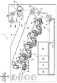
図1は本実施形態に係る画像形成装置1の内部構成を示す断面模式図である。
以下、図面を参照しながら、画像形成装置1の全体構成及び動作を説明する。
(1) Overall Configuration and Operation of Image Forming Apparatus FIG. 1 is a schematic sectional view showing the internal configuration of the image forming apparatus 1 according to this embodiment.
Hereinafter, the overall configuration and operation of the image forming apparatus 1 will be described with reference to the drawings.
画像形成装置1は、制御装置10、給紙装置20、感光体ユニット30、現像ユニット40、転写ユニット50、定着装置60、を備えて構成されている。画像形成装置1の上面(Z方向)には、画像が記録された用紙が排出・収容される排出トレイ1aが形成されている。
The image forming apparatus 1 includes a
制御装置10は、画像形成装置1の動作を制御する画像形成装置制御部11と、印刷処理要求に応じた画像データを準備するコントローラ部12、露光ヘッドLHの点灯を制御する露光制御部13、電源装置14等を有する。電源装置14は、後述する帯電ローラ32、現像ローラ42、一次転写ローラ52、給電ローラ54等に電圧を印加するとともに、露光ヘッドLH、給紙装置20、定着装置60及び備えられた各センサ等に電力を供給する。
The
コントローラ部12は、外部の情報送信装置(例えばパーソナルコンピュータ等)から入力された印刷情報を潜像形成用の画像情報に変換して予め設定されたタイミングで、駆動信号を露光ヘッドLHに出力する。本実施形態の露光ヘッドLHは、複数の発光素子(LED:Light Emitting Diode)が主走査方向に沿って線状に配列されたLEDヘッドにより構成されている。
The
画像形成装置1の底部には、給紙装置20が設けられている。給紙装置20は、用紙積載板21を備え、用紙積載板21の上面には多数の記録媒体としての用紙Pが積載される。用紙積載板21に積載され、規制板(不図示)で幅方向位置が決められた用紙Pは、上側から1枚ずつ用紙引き出し部22により前方(−X方向)に引き出された後、レジストローラ対23のニップ部まで搬送される。
A
感光体ユニット30は、給紙装置20の上方(Z方向)に、それぞれが並列して設けられ、回転駆動する像保持体としての感光体ドラム31を備えている。感光体ドラム31の回転方向にそって、帯電ローラ32、露光ヘッドLH、現像ユニット40、一次転写ローラ52、クリーニングブレード34が配置されている。帯電ローラ32には、帯電ローラ32の表面をクリーニングするクリーニングローラ33が対向、接触して配置されている。
The
現像ユニット40は、内部に現像剤が収容される現像ハウジング41を有する。現像ハウジング41内には、感光体ドラム31に対向して配置された現像ローラ42と、この現像ローラ42の背面側斜め下方には現像剤を現像ローラ42側へ撹拌搬送する一対のオーガ44、45が配設されている。現像ローラ42には、現像剤の層厚を規制する層規制部材46が近接配置されている。
現像ユニット40各々は、現像ハウジング41に収容される現像剤を除いて同様に構成され、それぞれがイエロー(Y)、マゼンタ(M)、シアン(C)、黒(K)のトナー像を形成する。
The developing
Each of the developing
回転する感光体ドラム31の表面は、帯電ローラ32により帯電され、露光ヘッドLHから出射する潜像形成光により静電潜像が形成される。感光体ドラム31上に形成された静電潜像は現像ローラ42によりトナー像として現像される。
The surface of the rotating
転写ユニット50は、各感光体ユニット30の感光体ドラム31にて形成された各色トナー像が多重転写される中間転写ベルト51、各感光体ユニット30にて形成された各色トナー像を中間転写ベルト51に順次転写(一次転写)する一次転写ローラ52を備えている。さらに、中間転写ベルト51上に重畳して転写された各色トナー像を用紙Pに一括転写(二次転写)する転写手段の一例としての二次転写ローラ53、二次転写ローラ53に二次転写バイアスを給電する給電部材の一例としての給電ローラ54とから構成されている。
The
各感光体ユニット30の感光体ドラム31に形成された各色トナー像は、画像形成装置制御部11により制御される電源装置14等から所定の転写電圧が印加された一次転写ローラ52により中間転写ベルト51上に順次静電転写(一次転写)され、各色トナーが重畳された重畳トナー像が形成される。
The toner image of each color formed on the
中間転写ベルト51上の重畳トナー像は、中間転写ベルト51の移動に伴って二次転写ローラ53が配置された領域(二次転写部T)に搬送される。重畳トナー像が二次転写部Tに搬送されると、そのタイミングに合わせて給紙装置20から用紙Pが二次転写部Tに供給される。そして、給電ローラ54には、画像形成装置制御部11により制御される電源装置14等から所定の転写電圧が印加され、レジストローラ対23から送り出され、搬送ガイドにより案内された用紙Pに中間転写ベルト51上の多重トナー像が一括転写される。
The superimposed toner image on the
感光体ドラム31表面の残留トナーは、クリーニングブレード34により除去され、廃現像剤収容部に回収される。感光体ドラム31の表面は、帯電ローラ32により再帯電される。尚、クリーニングブレード34で除去しきれず帯電ローラ32に付着した残留物は、帯電ローラ32に接触して回転するクリーニングローラ33表面に捕捉され、蓄積される。
The residual toner on the surface of the
定着装置60は、定着ユニット600、搬送ローラ対68、排出ローラ対69を備えて構成されている。定着ユニット600は、加熱モジュール61と加圧モジュール62を有し、加熱モジュール61と加圧モジュール62の圧接領域によって定着ニップ部N(定着領域)が形成される。
The fixing
転写ユニット50においてトナー像が転写された用紙Pは、トナー像が未定着の状態で搬送ガイドを経由して定着装置60に搬送される。定着装置60に搬送された用紙Pは、一対の加熱モジュール61と加圧モジュール62により、圧着と加熱の作用でトナー像が定着される。
定着トナー像が形成された用紙Pは、搬送ローラ対68を介して排出ローラ対69から画像形成装置1上面の排出トレイ1aに排出される。
The sheet P to which the toner image is transferred by the
The sheet P on which the fixed toner image is formed is ejected from the
(2)駆動伝達装置
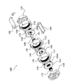
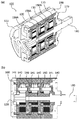
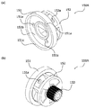
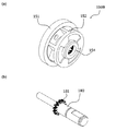
図2は遊星歯車機構を組み込んだ駆動伝達装置100の一例を示す分解斜視図、図3(a)は駆動伝達装置100の一例を示す一部断面斜視図、(b)は縦断面図、図4(a)は第1キャリア150Aの第1円板部151側に視点をおいた斜視図、(b)は外歯153側に視点をおいた斜視図、図5(a)は第2キャリア150Bの第2円板部152側に視点をおいた斜視図、(b)は出力軸180の斜視図、図6は内歯歯車130の斜視図、図7(a)は押え部材160の斜視図、(b)は押え部材160が回転軸141と接触する側に視点をおいた斜視図、(c)は遊星歯車140の斜視図、(d)は回転軸141の斜視図、図8は遊星歯車140の第1キャリア150Aへの組み付けを示す斜視図である。
以下、図面を参照しながら駆動伝達装置100の構成と動作について説明する。
(2) Drive Transmission Device FIG. 2 is an exploded perspective view showing an example of the
Hereinafter, the configuration and operation of the
(2.1)駆動伝達装置の全体構成
図2には、遊星歯車機構を3段構成とした駆動伝達装置100の一例が示されているが、本実施形態に係る駆動伝達装置100は必要とされる減速比に応じて複数の遊星歯車機構を重ね合わせて構成することができる。
(2.1) Overall Configuration of Drive Transmission Device FIG. 2 shows an example of the
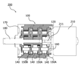
図3(a)、(b)に示すように、駆動伝達装置100は、第1支持蓋110、駆動源から駆動力を受けて回転する太陽歯車120、太陽歯車120と同軸上に配置された内歯歯車130、太陽歯車120と内歯歯車130とに噛み合い自転しながら公転する複数の遊星歯車140、遊星歯車140の回転軸141を支持し、遊星歯車140の公転により出力軸180を回転中心として回転する回転部材としてのキャリア150、キャリア150の一面側で遊星歯車140の回転軸141の一端141aに接触して回転軸141を押える押え部材160、第2支持蓋170、第1支持蓋110と第2支持蓋170の間で複数の遊星歯車機構を重ね合わせて保持する連結部材190から構成されている。
As shown in FIGS. 3A and 3B, the
(2.2)太陽歯車
太陽歯車120は、駆動源としてのモータM(不図示)の出力軸に固定され、モータMの駆動力を遊星歯車140に伝達する。
(2.2) Sun Gear The
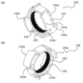
(2.3)キャリア
図4(a)、(b)に示すように、回転部材の一例としてのキャリア150は、第1円板部151、第1円板部151と相対する第2円板部152、第2円板部152から回転軸線方向に突出した外歯153が一体として形成されている第1キャリア150A(図4(a)、(b)参照)と、第2円板部152の内側に内歯154が一体として形成されている第2キャリア150B(図5(a)参照)から構成されている。
(2.3) Carrier As shown in FIGS. 4A and 4B, a carrier 150 as an example of a rotating member includes a
第1キャリア150Aは、駆動伝達装置100を複数の遊星歯車機構を重ね合わせて多段の遊星歯車機構として構成する場合に、出力側の最終段以外に使用され、外歯153が次段の遊星歯車機構の遊星歯車140に噛合して遊星歯車140を自転させる。
第2キャリア150Bは、出力側の最終段に使用され、内歯154が出力軸180の外歯181に噛合して駆動伝達装置100の出力軸180に駆動源からの減速された回転を伝達する。
The
The
図4に示すように、第2円板部152には有底の穴152aが形成され、第1円板部151には貫通孔151aが形成されている。本実施形態においては、一対の穴152aと貫通孔151aは遊星歯車140に対応してそれぞれ3箇所に設けられ、遊星歯車140を回転支持する回転軸141が貫通孔151aを挿通して他端141bが穴152aに嵌まり合うことでキャリア150の周縁部で遊星歯車140を回転自在に支持する。
As shown in FIG. 4, a bottomed
第1円板部151は、第2円板部152に比して、大径の円板形状であり、表面には環状の凹部151bが形成され、後述する押え部材160が周縁部に形成された突起部162、163が凹部151bに嵌め合わされた状態でキャリア150の一面側に固定されている。押え部材160は、第1円板部151の貫通孔151aと第2円板部152の穴152aに支持された回転軸141の一端141aに接触して回転軸141を押えている。
The
第1円板部151の周縁部には回転軸141の軸方向に内歯歯車130の端面から突出するようにフランジ部151cが形成されている。
その結果、遊星歯車機構を複数段重ね合わせた状態では、フランジ部151cは互いに隣接する内歯歯車130の双方の内面132で位置決めされ、内歯歯車130に回転軸線と交差する方向(垂直方向)の外力を受けた場合にも重ね合わされた遊星歯車機構の互いの軸ずれを抑制している。
A
As a result, in a state in which the planetary gear mechanisms are stacked in a plurality of stages, the
第2円板部152は、内歯歯車130の内歯133の歯先円よりも小径とされ、遊星歯車140が組み込まれた状態で、出力軸180に挿通されて遊星歯車140が内歯歯車130の中空部の内面132に形成された内歯133に噛合する。
The
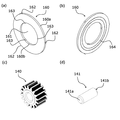
(2.4)内歯歯車
図5に示すように、内歯歯車130は、全体が中空部を有する円筒状の筒体131と、筒体131の内面132の中央部に形成された内歯133からなる。
内歯133が形成された内面132の両側は円筒形状で、一端側にはキャリア150の第1円板部151のフランジ部151cが当接して、キャリア150を外側から回転支持している。
(2.4) Internal Gear As shown in FIG. 5, the
Both sides of the
筒体131には、入力軸の軸線方向に突出した凸部131aと、凸部131aと嵌り合う凹部131bが形成され、複数段重ね合わせて構成される場合、凸部131aと凹部131bが嵌り合って遊星歯車機構が同軸的に重ね合わされる。
The
(2.5)押え部材
図7(a)に示すように、押え部材160は、中心孔161を有するリング状の板部材であり、外縁部160a及び内縁部160bには、複数の係合部としての突起部162、163が形成されている。
押え部材160は、キャリア150に遊星歯車140が回転軸141を介して回転自在に支持された状態で、第1円板部151に形成された環状の凹部151bに突起部162、163が圧入されて嵌め合わされた状態でキャリア150の一面側に固定されている。
その結果、押え部材160は、第1円板部151の貫通孔151aと第2円板部152の穴152aに支持された回転軸141の一端141aに接触して回転軸141を押えている。
(2.5) Pressing Member As shown in FIG. 7A, the pressing
In the holding
As a result, the pressing
図7(b)に示すように、押え部材160の回転軸141の一端141aと接する摺動面には、溝164が形成されている。溝164は当接される回転軸141の一端141aとの間に潤滑剤を介在させ、回転軸141の回転摺動性を向上させている。
As shown in FIG. 7B, a
(2.6)材質
第1支持蓋110、太陽歯車120、内歯歯車130、遊星歯車140、キャリア150、第2支持蓋170は合成樹脂材料を用いた成形品で構成される。合成樹脂材料としては、POM(ポリアセタール)、PA(ポリアミド)、PC(ポリカーボネイト)、PET(ポリエチレンテレフタレート)、PPS(ポリフェニレンサルファイド)、LCP(液晶ポリマー)又はこれらの合成樹脂にガラス繊維又は炭素繊維を添加した強化合成樹脂が挙げられる。
(2.6) Material The
押え部材160は、キャリア150の材料である合成樹脂又は強化合成樹脂よりも摺動性の高い摺動材料を用いて成形される。具体的には、一般POM(ポリアセタール)の特性に加えて、耐摩耗性及び摺動性をより高くした高摺動POM(ポリアセタール)が挙げられる。
また、押え部材160の材料としては、金属を用いることもできる。具体的には、ステンレス材が挙げられる。
押え部材160の材料として、これら摺動材料又は金属を用いた場合には、複数段重ね合わせて構成される場合に互いに回転するキャリア150との回転摺動性を向上させることができる。
The pressing
Further, as the material of the
When these sliding materials or metals are used as the material of the
(2.8)動作
モータMの駆動で太陽歯車120が回転駆動される。そして、太陽歯車120が回転駆動を行うと、3つの遊星歯車140の各々が、回転軸141を回転中心として自転する。また、3つの遊星歯車140の各々は、内歯歯車130の内歯133と噛み合っているために、内歯歯車130に沿って公転する。
(2.8) Operation The
そして、3つの遊星歯車140の公転が開始されると、遊星歯車140を支持する第1キャリア150Aは、太陽歯車120の回転に対し減速回転を開始する。第1キャリア150Aの減速回転が開始されると、第1キャリア150Aに一体に形成された外歯153の減速回転が開始される。
When the revolution of the three
遊星歯車機構が、図3に示すように複数段重ね合わせて構成されている場合(図3の例では3段)には、第1キャリア150Aの第2円板部152の外面に設けられ減速回転する外歯153が2段目の遊星歯車機構の入力となる。
そして、2段目の遊星歯車機構では、2段目の内歯歯車130と外歯153とに噛み合う2段目の遊星歯車140が、2段目の第1キャリア150Aにより支持されて、自転しながら外歯153の外周を公転する。そして、公転する遊星歯車140を支持する2段目の第1キャリア150Aが減速回転する。
When the planetary gear mechanism is configured by stacking a plurality of stages as shown in FIG. 3 (three stages in the example of FIG. 3), the planetary gear mechanism is provided on the outer surface of the
Then, in the second-stage planetary gear mechanism, the second-stage
減速回転する2段目の第1キャリア150Aの第2円板部152の外面には外歯153が設けられており、3段目の内歯歯車130と3段目の外歯153とに噛み合う3段目の遊星歯車140が、3段目の第2キャリア150Bにより支持されて、自転しながら外歯153の外周を公転する。公転する遊星歯車140を支持する3段目の第2キャリア150Bの第2円板部152の内側に形成された内歯154が出力軸180の外歯181に噛合して駆動伝達装置100の出力軸180には3段に減速された回転が伝達される。
(3)駆動伝達装置を用いた駆動装置
遊星歯車機構を重ね合わせた駆動伝達装置100は、太陽歯車120の回転、遊星歯車140の公転(キャリア150の回転)、内歯歯車130の回転のいずれかを固定、一つを入力、一つを出力に接続して使用される。
(3) Drive Device Using Drive Transmission Device The
「実施例1」
図9は本実施例に係るギヤードモータ200の縦断面模式図である。
ギヤードモータ200は、第1支持蓋110に固定された駆動源としてのモータ210と、モータ210の出力軸211に挿通された太陽歯車120、遊星歯車140を回転支持するキャリア150、遊星歯車140が噛合する内歯歯車130からなる遊星歯車機構が第2支持蓋170で一体として3段重ね合わされた駆動伝達装置100からなる減速機付きモータである。
"Example 1"
FIG. 9 is a schematic vertical sectional view of the geared
The geared
ギヤードモータ200は、モータ210の回転駆動力が出力軸211から太陽歯車120に伝達され、駆動伝達装置100の出力軸180から減速されて出力される。ギヤードモータ200は、駆動伝達装置100の太陽歯車120に駆動源としてのモータ210が一体として接続されて回転ムラやロックを抑制された駆動装置として利用できる。
In the geared
「実施例2」
図10は本実施例に係る感光体ドラム31の縦断面模式図である。
駆動伝達装置100Aは、内歯歯車130の筒体131が感光体ドラム31に嵌入されて、太陽歯車120がドラムシャフト311を介して駆動源としてのモータM(不図示)に接続されている。
"Example 2"
FIG. 10 is a schematic vertical sectional view of the
In the
駆動源としてのモータMからの駆動力はドラムシャフト311を介して駆動伝達装置100Aに伝達され、太陽歯車120から入力される回転駆動力は3段重ね合せて構成された遊星歯車機構で減速される。
駆動伝達装置100Aは、第2キャリア150Bの出力軸154Bが感光体ユニット30に固定された状態で内歯歯車130が回転し、回転駆動は内歯歯車130の減速回転ともに内歯歯車130の筒体131に固定された感光体ドラム31に回転ムラが抑制されて伝達される。
The driving force from the motor M as a driving source is transmitted to the
In the
「実施例3」
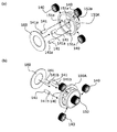
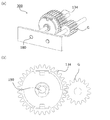
図11(a)は本実施例に係る外歯減速機構300の斜視図、(b)は正面図である。
外歯減速機構300は、駆動伝達装置100Bを構成する内歯歯車130が筒体131の外面に外歯134を有し、外歯134に噛合する被駆動体Gに減速回転を伝達する。
"Example 3"
FIG. 11A is a perspective view of the external
In the external
外歯減速機構300は、太陽歯車120から入力される回転駆動力は遊星歯車機構で減速され、出力軸180が固定された状態で内歯歯車130が回転し、内歯歯車130の減速回転ともに内歯歯車130の外面に設けられた外歯134に噛合する歯車135に伝達される。
In the external
「実施例4」
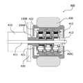
図12はインホイール機構400の縦断面模式図である。
インホイール機構400は、駆動源としてのモータ410の出力軸411に駆動伝達装置100Cが挿通されてホイール412の内面に固定されている。ホイール412は、モータ410の出力軸411に対して軸受413を介して回転支持され、モータ410の保持部材420に固定された第2キャリア150Bの出力軸154Bの外周面には軸受421を介してホイール422がホイール412に対向して回転支持されている。
"Example 4"
FIG. 12 is a schematic vertical sectional view of the in-
In the in-
このように構成されるインホイール機構400においては、モータ410の回転駆動が3段重ね合わされて構成された駆動伝達装置100Cで減速されて、内歯歯車130の外面に固定されたホイール412、422に回転ムラが抑制されて伝達される。
ホイール412、422には、例えば、ゴム製のロール部材430を装着することができる。
In the in-
A
1・・・画像形成装置
10・・・制御装置
20・・・給紙装置
30・・・感光体ユニット
40・・・現像ユニット
50・・・転写ユニット
60・・・定着装置
100・・・駆動伝達装置
110・・・第1支持蓋
120・・・太陽歯車
130・・・内歯歯車
131・・・筒体
132・・・内面(筒体)
133・・・内歯
134・・・外歯
140・・・遊星歯車
141・・・回転軸
150・・・キャリア
150A・・・第1キャリア
150B・・・第2キャリア
151・・・第1円板部
152・・・第2円板部
153・・・外歯
154・・・内歯
160・・・押え部材
161・・・中心孔
162、163・・・突起部
164・・・溝
170・・・第2支持蓋
180・・・出力軸
190・・・連結部材
200・・・ギヤードモータ
300・・・外歯減速機構
400・・・インホイール機構
1...
133...
Claims (7)
中空部を有し、前記中空部の内面に内歯が設けられ前記太陽歯車と同軸上に配置された内歯歯車と、
前記太陽歯車と前記内歯歯車とに噛み合い自転しながら公転する遊星歯車と、
前記遊星歯車の回転軸を支持し、前記遊星歯車の公転により出力軸を回転中心として回転する回転部材と、
前記回転部材の一面側で前記遊星歯車の前記回転軸の一端に接触して前記回転軸を押える押え部材と、を備え、
前記回転部材は、前記回転軸の軸方向に前記内歯歯車の端面から突出するように形成されたフランジ部を有し、複数段重ね合わせた状態で、前記フランジ部は互いに隣接する前記内歯歯車の双方の前記内面で位置決めされる、
ことを特徴とする駆動伝達装置。 A sun gear that rotates by receiving driving force,
An internal gear having a hollow portion, and internal teeth provided on the inner surface of the hollow portion and arranged coaxially with the sun gear,
A planetary gear that revolves while rotating while meshing with the sun gear and the internal gear,
A rotation member that supports the rotation shaft of the planetary gear and that rotates around the output shaft by the revolution of the planetary gear,
A pressing member that contacts one end of the rotation shaft of the planetary gear on one surface side of the rotation member and presses the rotation shaft,
The rotating member has a flange portion formed so as to protrude from the end face of the internal gear in the axial direction of the rotary shaft, the inner teeth in a state in which plural stages overlapped, the flange portion is adjacent to each other Positioned on both said inner surfaces of the gear wheel,
A drive transmission device characterized by the above.
ことを特徴とする請求項1に記載の駆動伝達装置。 The rotating member is integrally formed with a first disc part and a second disc part facing the first disc part, and one of the first disc part and the second disc part is formed. A bottomed hole is formed, a through hole is formed in the other of the first disk portion and the second disk portion, and the rotary shaft inserted through the through hole is formed by the through hole and the hole. Supported,
The drive transmission device according to claim 1, wherein:
ことを特徴とする請求項2に記載の駆動伝達装置。 The rotating member has an annular recess in the first disk portion, and the pressing member has one side surface of the rotating member in a state where an engaging projection formed on a peripheral edge portion is press-fitted into the recess and fitted together. Fixed to,
The drive transmission device according to claim 2, wherein:
ことを特徴とする請求項1ないし3のいずれか1項に記載の駆動伝達装置。 The pressing member is made of a material having a friction coefficient lower than that of the material of the rotating member on a contact surface in contact with one end of the rotating shaft.
The drive transmission device according to claim 1, wherein the drive transmission device is a drive transmission device.
ことを特徴とする請求項1ないし3のいずれか1項に記載の駆動伝達装置。 The pressing member is made of metal or resin material,
The drive transmission device according to claim 1, wherein the drive transmission device is a drive transmission device.
ことを特徴とする請求項1ないし5のいずれか1項に記載の駆動伝達装置。 The pressing member includes a groove for allowing a lubricant to intervene between the contact surface and one end of the rotating shaft, which is in contact with the one end of the rotating shaft.
The drive transmission device according to claim 1, wherein the drive transmission device is a drive transmission device.
前記駆動伝達装置の前記回転部材の回転力を伝達する駆動手段と、
前記駆動手段の駆動を受けて画像を形成する画像形成部と、を含む、
ことを特徴とする画像形成装置。 A motor for rotationally driving the sun gear of the drive transmission device according to any one of claims 1 to 6,
Drive means for transmitting the rotational force of the rotary member of the drive transmission device;
An image forming unit that forms an image by being driven by the driving unit,
An image forming apparatus characterized by the above.
Priority Applications (2)
| Application Number | Priority Date | Filing Date | Title |
|---|---|---|---|
| JP2016006062A JP6743390B2 (en) | 2016-01-15 | 2016-01-15 | Drive transmission device and image forming apparatus |
| US15/233,569 US10423113B2 (en) | 2016-01-15 | 2016-08-10 | Driving force transmission device and image forming apparatus |
Applications Claiming Priority (1)
| Application Number | Priority Date | Filing Date | Title |
|---|---|---|---|
| JP2016006062A JP6743390B2 (en) | 2016-01-15 | 2016-01-15 | Drive transmission device and image forming apparatus |
Publications (2)
| Publication Number | Publication Date |
|---|---|
| JP2017125588A JP2017125588A (en) | 2017-07-20 |
| JP6743390B2 true JP6743390B2 (en) | 2020-08-19 |
Family
ID=59315055
Family Applications (1)
| Application Number | Title | Priority Date | Filing Date |
|---|---|---|---|
| JP2016006062A Active JP6743390B2 (en) | 2016-01-15 | 2016-01-15 | Drive transmission device and image forming apparatus |
Country Status (2)
| Country | Link |
|---|---|
| US (1) | US10423113B2 (en) |
| JP (1) | JP6743390B2 (en) |
Families Citing this family (2)
| Publication number | Priority date | Publication date | Assignee | Title |
|---|---|---|---|---|
| USD827689S1 (en) * | 2017-05-22 | 2018-09-04 | Daniel Turner | Orbital gear replacement insert |
| JP7297629B2 (en) * | 2019-10-04 | 2023-06-26 | ニデックプレシジョン株式会社 | Planetary gear mechanism and geared motor |
Family Cites Families (14)
| Publication number | Priority date | Publication date | Assignee | Title |
|---|---|---|---|---|
| US4756212A (en) * | 1987-01-12 | 1988-07-12 | General Motors Corporation | Planet gear carrier assembly |
| FR2684732B1 (en) * | 1991-12-10 | 1994-02-18 | Somfy | PLANETARY REDUCER FOR TUBULAR MOTOR. |
| FR2695700B1 (en) * | 1992-09-16 | 1994-11-18 | Somfy | Planetary reducer. |
| CA2305135A1 (en) * | 1997-10-07 | 1999-04-15 | Interroll Holding Ag | A drum motor |
| JP2000274495A (en) * | 1999-03-25 | 2000-10-03 | Canon Precision Inc | 3K type mysterious planetary gear reduction mechanism |
| JP4617426B2 (en) * | 2001-05-31 | 2011-01-26 | 株式会社 神崎高級工機製作所 | Work vehicle transmission |
| JP2007056885A (en) * | 2005-08-22 | 2007-03-08 | Nidec-Shimpo Corp | Revolution support structure of carrier in planetary gear reducer |
| JP4899083B2 (en) * | 2005-08-29 | 2012-03-21 | Smc株式会社 | Automatic reduction ratio switching device |
| TW201216581A (en) * | 2010-10-15 | 2012-04-16 | Wistron Corp | Power supply and system thereof |
| JP2012092907A (en) * | 2010-10-27 | 2012-05-17 | Ricoh Co Ltd | Planetary gear speed reducer |
| JP5861916B2 (en) * | 2011-02-01 | 2016-02-16 | 株式会社リコー | Planetary gear device and image forming apparatus |
| WO2012134474A1 (en) * | 2011-03-31 | 2012-10-04 | Ingersoll-Rand Company | Ring gears configured to encase in-line torque transducers for power tools |
| CN103775566B (en) * | 2012-10-26 | 2018-08-21 | 德昌电机(深圳)有限公司 | Gear drive and its assembly method |
| JP2015081638A (en) | 2013-10-22 | 2015-04-27 | 株式会社リコー | Rotation drive device and image forming apparatus |
-
2016
- 2016-01-15 JP JP2016006062A patent/JP6743390B2/en active Active
- 2016-08-10 US US15/233,569 patent/US10423113B2/en active Active
Also Published As
| Publication number | Publication date |
|---|---|
| US20170205753A1 (en) | 2017-07-20 |
| US10423113B2 (en) | 2019-09-24 |
| JP2017125588A (en) | 2017-07-20 |
Similar Documents
| Publication | Publication Date | Title |
|---|---|---|
| US7751746B2 (en) | Device for driving rotary body with mechanism for dampening fluctuation in rotation velocity | |
| US11112750B2 (en) | Development cartridge having a switch member to rotate developing unit to a development position | |
| US9897937B2 (en) | Development cartridge and electrophotographic image forming apparatus using the same | |
| US9163701B2 (en) | Gear transmission device and image forming apparatus including the same | |
| US8900088B2 (en) | Clutch mechanism and image forming apparatus including same | |
| US9879733B2 (en) | Power transmission device and image forming apparatus including same | |
| US9322458B2 (en) | Gear transmission device, process unit including the gear transmission device, and image forming apparatus including same | |
| US8585537B2 (en) | Driving device and image forming apparatus | |
| US9354548B2 (en) | Power transmitting apparatus and image forming apparatus implementing the same | |
| CN102129187A (en) | Drive transmission device and image forming apparatus | |
| JP6136835B2 (en) | Drive switching device and image forming apparatus | |
| US20060268081A1 (en) | Coupling device and image forming apparatus using the same | |
| JP6743390B2 (en) | Drive transmission device and image forming apparatus | |
| CN103807365B (en) | Drive force transfering device and image forming apparatus | |
| JP6481656B2 (en) | Planetary gear mechanism and image forming apparatus | |
| JP6146035B2 (en) | Image forming apparatus | |
| CN100474142C (en) | Method of driving device for driving developers and image forming apparatus having the device for driving developers | |
| US9921537B2 (en) | Drive mechanism that changes speed of drive force, and image forming apparatus having the drive mechanism | |
| JP6565372B2 (en) | Driving force transmission device and image forming apparatus | |
| JP2019173910A (en) | One-way clutch, sheet conveyance device, and image forming apparatus | |
| JP5167894B2 (en) | Image forming apparatus | |
| JP7091717B2 (en) | Planetary gear mechanism, drive device and image forming device | |
| JP6697710B2 (en) | Speed switching device, drive device and image forming device | |
| JP4843510B2 (en) | Image forming apparatus | |
| JP2013045033A (en) | Driving device and image forming apparatus |
Legal Events
| Date | Code | Title | Description |
|---|---|---|---|
| A621 | Written request for application examination |
Free format text: JAPANESE INTERMEDIATE CODE: A621 Effective date: 20181122 |
|
| A977 | Report on retrieval |
Free format text: JAPANESE INTERMEDIATE CODE: A971007 Effective date: 20191004 |
|
| A131 | Notification of reasons for refusal |
Free format text: JAPANESE INTERMEDIATE CODE: A131 Effective date: 20191023 |
|
| A521 | Written amendment |
Free format text: JAPANESE INTERMEDIATE CODE: A523 Effective date: 20191219 |
|
| A131 | Notification of reasons for refusal |
Free format text: JAPANESE INTERMEDIATE CODE: A131 Effective date: 20200331 |
|
| A521 | Written amendment |
Free format text: JAPANESE INTERMEDIATE CODE: A523 Effective date: 20200520 |
|
| TRDD | Decision of grant or rejection written | ||
| A01 | Written decision to grant a patent or to grant a registration (utility model) |
Free format text: JAPANESE INTERMEDIATE CODE: A01 Effective date: 20200630 |
|
| A61 | First payment of annual fees (during grant procedure) |
Free format text: JAPANESE INTERMEDIATE CODE: A61 Effective date: 20200713 |
|
| R150 | Certificate of patent or registration of utility model |
Ref document number: 6743390 Country of ref document: JP Free format text: JAPANESE INTERMEDIATE CODE: R150 |
|
| S533 | Written request for registration of change of name |
Free format text: JAPANESE INTERMEDIATE CODE: R313533 |
|
| R350 | Written notification of registration of transfer |
Free format text: JAPANESE INTERMEDIATE CODE: R350 |