JP6743298B2 - Furniture drive - Google Patents
Furniture drive Download PDFInfo
- Publication number
- JP6743298B2 JP6743298B2 JP2019520559A JP2019520559A JP6743298B2 JP 6743298 B2 JP6743298 B2 JP 6743298B2 JP 2019520559 A JP2019520559 A JP 2019520559A JP 2019520559 A JP2019520559 A JP 2019520559A JP 6743298 B2 JP6743298 B2 JP 6743298B2
- Authority
- JP
- Japan
- Prior art keywords
- furniture
- movable
- furniture part
- actuating
- locking
- Prior art date
- Legal status (The legal status is an assumption and is not a legal conclusion. Google has not performed a legal analysis and makes no representation as to the accuracy of the status listed.)
- Active
Links
Images


Classifications
-
- A—HUMAN NECESSITIES
- A47—FURNITURE; DOMESTIC ARTICLES OR APPLIANCES; COFFEE MILLS; SPICE MILLS; SUCTION CLEANERS IN GENERAL
- A47B—TABLES; DESKS; OFFICE FURNITURE; CABINETS; DRAWERS; GENERAL DETAILS OF FURNITURE
- A47B51/00—Cabinets with means for moving compartments up and down
-
- A—HUMAN NECESSITIES
- A47—FURNITURE; DOMESTIC ARTICLES OR APPLIANCES; COFFEE MILLS; SPICE MILLS; SUCTION CLEANERS IN GENERAL
- A47B—TABLES; DESKS; OFFICE FURNITURE; CABINETS; DRAWERS; GENERAL DETAILS OF FURNITURE
- A47B46/00—Cabinets, racks or shelf units, having one or more surfaces adapted to be brought into position for use by extending or pivoting
- A47B46/005—Cabinets, racks or shelf units, having one or more surfaces adapted to be brought into position for use by extending or pivoting by displacement in a vertical plane; by rotating about a horizontal axis
-
- E—FIXED CONSTRUCTIONS
- E05—LOCKS; KEYS; WINDOW OR DOOR FITTINGS; SAFES
- E05F—DEVICES FOR MOVING WINGS INTO OPEN OR CLOSED POSITION; CHECKS FOR WINGS; WING FITTINGS NOT OTHERWISE PROVIDED FOR, CONCERNED WITH THE FUNCTIONING OF THE WING
- E05F1/00—Closers or openers for wings, not otherwise provided for in this subclass
- E05F1/08—Closers or openers for wings, not otherwise provided for in this subclass spring-actuated, e.g. for horizontally sliding wings
-
- F—MECHANICAL ENGINEERING; LIGHTING; HEATING; WEAPONS; BLASTING
- F16—ENGINEERING ELEMENTS AND UNITS; GENERAL MEASURES FOR PRODUCING AND MAINTAINING EFFECTIVE FUNCTIONING OF MACHINES OR INSTALLATIONS; THERMAL INSULATION IN GENERAL
- F16M—FRAMES, CASINGS OR BEDS OF ENGINES, MACHINES OR APPARATUS, NOT SPECIFIC TO ENGINES, MACHINES OR APPARATUS PROVIDED FOR ELSEWHERE; STANDS; SUPPORTS
- F16M11/00—Stands or trestles as supports for apparatus or articles placed thereon Stands for scientific apparatus such as gravitational force meters
- F16M11/02—Heads
- F16M11/04—Means for attachment of apparatus; Means allowing adjustment of the apparatus relatively to the stand
- F16M11/043—Allowing translations
- F16M11/046—Allowing translations adapted to upward-downward translation movement
-
- F—MECHANICAL ENGINEERING; LIGHTING; HEATING; WEAPONS; BLASTING
- F16—ENGINEERING ELEMENTS AND UNITS; GENERAL MEASURES FOR PRODUCING AND MAINTAINING EFFECTIVE FUNCTIONING OF MACHINES OR INSTALLATIONS; THERMAL INSULATION IN GENERAL
- F16M—FRAMES, CASINGS OR BEDS OF ENGINES, MACHINES OR APPARATUS, NOT SPECIFIC TO ENGINES, MACHINES OR APPARATUS PROVIDED FOR ELSEWHERE; STANDS; SUPPORTS
- F16M11/00—Stands or trestles as supports for apparatus or articles placed thereon Stands for scientific apparatus such as gravitational force meters
- F16M11/02—Heads
- F16M11/04—Means for attachment of apparatus; Means allowing adjustment of the apparatus relatively to the stand
- F16M11/043—Allowing translations
- F16M11/048—Allowing translations adapted to forward-backward translation movement
-
- E—FIXED CONSTRUCTIONS
- E05—LOCKS; KEYS; WINDOW OR DOOR FITTINGS; SAFES
- E05Y—INDEXING SCHEME RELATING TO HINGES OR OTHER SUSPENSION DEVICES FOR DOORS, WINDOWS OR WINGS AND DEVICES FOR MOVING WINGS INTO OPEN OR CLOSED POSITION, CHECKS FOR WINGS AND WING FITTINGS NOT OTHERWISE PROVIDED FOR, CONCERNED WITH THE FUNCTIONING OF THE WING
- E05Y2201/00—Constructional elements; Accessories therefore
- E05Y2201/40—Motors; Magnets; Springs; Weights; Accessories therefore
- E05Y2201/404—Motors; Magnets; Springs; Weights; Accessories therefore characterised by the function
- E05Y2201/416—Motors; Magnets; Springs; Weights; Accessories therefore characterised by the function for counterbalancing
-
- E—FIXED CONSTRUCTIONS
- E05—LOCKS; KEYS; WINDOW OR DOOR FITTINGS; SAFES
- E05Y—INDEXING SCHEME RELATING TO HINGES OR OTHER SUSPENSION DEVICES FOR DOORS, WINDOWS OR WINGS AND DEVICES FOR MOVING WINGS INTO OPEN OR CLOSED POSITION, CHECKS FOR WINGS AND WING FITTINGS NOT OTHERWISE PROVIDED FOR, CONCERNED WITH THE FUNCTIONING OF THE WING
- E05Y2900/00—Application of doors, windows, wings or fittings thereof
- E05Y2900/20—Application of doors, windows, wings or fittings thereof for furnitures, e.g. cabinets
-
- F—MECHANICAL ENGINEERING; LIGHTING; HEATING; WEAPONS; BLASTING
- F16—ENGINEERING ELEMENTS AND UNITS; GENERAL MEASURES FOR PRODUCING AND MAINTAINING EFFECTIVE FUNCTIONING OF MACHINES OR INSTALLATIONS; THERMAL INSULATION IN GENERAL
- F16M—FRAMES, CASINGS OR BEDS OF ENGINES, MACHINES OR APPARATUS, NOT SPECIFIC TO ENGINES, MACHINES OR APPARATUS PROVIDED FOR ELSEWHERE; STANDS; SUPPORTS
- F16M2200/00—Details of stands or supports
- F16M2200/04—Balancing means
- F16M2200/041—Balancing means for balancing rotational movement of the head
-
- F—MECHANICAL ENGINEERING; LIGHTING; HEATING; WEAPONS; BLASTING
- F16—ENGINEERING ELEMENTS AND UNITS; GENERAL MEASURES FOR PRODUCING AND MAINTAINING EFFECTIVE FUNCTIONING OF MACHINES OR INSTALLATIONS; THERMAL INSULATION IN GENERAL
- F16M—FRAMES, CASINGS OR BEDS OF ENGINES, MACHINES OR APPARATUS, NOT SPECIFIC TO ENGINES, MACHINES OR APPARATUS PROVIDED FOR ELSEWHERE; STANDS; SUPPORTS
- F16M2200/00—Details of stands or supports
- F16M2200/06—Arms
- F16M2200/063—Parallelogram arms
Description
本発明は、家具本体に対して相対的に可動に支持された家具部分のための家具駆動装置であって、
−可動の家具部分を動かすための、揺動可能に支持された少なくとも1つの作動アームと、
−補償装置であって、補償装置は、少なくとも1つの作動アームに、場合によっては荷重が掛けられる家具部分の重力とは逆向きの補償力を及ぼし、補償装置は、少なくとも1つの作動アームに力を加えるためのばね装置を有する、補償装置と、
−少なくとも1つの作動アームへばね装置の力を伝達するための伝達機構であって、伝達機構は、可動に支持された少なくとも1つの作動部材と、作動輪郭と、ばね装置により荷重が掛けられる押圧部材とを有し、押圧部材は、少なくとも1つの作動アームの運動時に作動輪郭に沿って走行可能である、伝達機構と、
を備える、家具駆動装置に関する。
The present invention is a furniture drive device for a furniture part that is movably supported relative to a furniture body,
At least one actuating arm pivotably supported for moving the movable furniture part;
The compensator exerts on the at least one actuating arm a compensating force opposite to the gravity of the possibly loaded furniture part, the compensator exerting a force on the at least one actuating arm. A compensating device having a spring device for applying
A transmission mechanism for transmitting the force of the spring device to the at least one actuating arm, the transmission mechanism comprising at least one movably supported actuating member, an actuating contour and a pressing force exerted by the spring device. A transmission member, the pressing member being capable of traveling along an operating contour during movement of the at least one operating arm;
The present invention relates to a furniture drive device.
さらに、本発明は、前述のタイプの家具駆動装置を備えた家具に関する。 Furthermore, the invention relates to furniture with a furniture drive of the type described above.
そのような家具駆動装置を使用するときの特別な試みは、ばね装置の、作動アームに及ぼされるトルクが、可動の家具部分のその都度の重量および/または様々な荷重状況に適合させられることにある。このトルクが家具部分の重量に関してかつ/または荷重状況に関して小さすぎると、可動の家具部分は、家具本体に対して相対的に上昇した終端位置へ全く動かすことができない。これに対して、作動アームに作用するトルクが過度に大きく調整されると、可動の家具部分が、過剰に大きな力でもって、家具本体に対して相対的に上昇した終端位置へ跳ね上がることが十分に起こり得る。 A special attempt when using such furniture drives is that the torque exerted on the actuating arm of the spring device is adapted to the respective weight and/or different load situations of the movable furniture part. is there. If this torque is too small with respect to the weight of the furniture part and/or with respect to the load situation, the movable furniture part cannot be moved at all to the raised end position relative to the furniture body. On the other hand, if the torque acting on the actuating arm is adjusted to an excessively large value, it is sufficient that the movable furniture part jumps up to the end position that is relatively raised with respect to the furniture body with an excessively large force. Can happen to.
国際公開第2010/006346号(WO 2010/006346 A2)において、家具本体に対して降下可能な家具部分のための家具駆動装置が開示されており、この場合、家具駆動装置は、家具部分を駆動するための第1の電動モータと、家具部分の重量を検出するための測定装置と、ばねを具備する補償装置とを有し、ばねに、第2の電動モータによって、可動の家具部分の測定された重量に応じて、様々にプリロードを掛けることが可能である。しかしまた、電気的な構成要素を有するそのような家具駆動装置の製造は、より高いコスト負担を伴う。 International Publication No. 2010/006346 (WO 2010/006346 A2) discloses a furniture driving device for a furniture part that can be lowered with respect to a furniture body. In this case, the furniture driving device drives the furniture part. To measure the weight of the furniture part, and a compensator comprising a spring, the spring measuring the movable furniture part by the second electric motor. Various preloads can be applied depending on the weight applied. However, the production of such furniture drives with electrical components also entails a higher cost burden.
米国特許出願公開第2011/0266937A1号明細書(US2011/0266937A1)は、可動の家具部分を動かすための、自動調整式の動力駆動装置を開示している。この場合、作動アームは、可動の家具部分の重量に応じて、様々に揺動させられ、これによって可動の家具部分の重量を補償するためにエネルギ蓄積器に様々にプリロードを掛ける。作動アームの調整が行われた後で、作動アームの、前調整された位置は、ラッチによって固定することが可能であり、この場合、ラッチは、グリップが配置されたボーデンケーブルによって、操作することが可能である。 U.S. Patent Application Publication No. 2011/0266937A1 (US2011/0266937A1) discloses a self-adjusting power drive for moving movable furniture parts. In this case, the actuating arm is swung differently depending on the weight of the movable furniture part, thereby preloading the energy store differently to compensate for the weight of the movable furniture part. After the adjustment of the actuating arm has been carried out, the pre-adjusted position of the actuating arm can be fixed by means of a latch, in which case the latch can be operated by means of a Bowden cable in which the grip is arranged. Is possible.
欧州特許出願公開第1820420号明細書(EP 1 820 420 A1)は、降下可能な家具部分を有する家具を開示している。この場合、補償装置に、可動の家具部分の重量を補償するためのガスばねが設けられている。ガスばねは、走行可能なキャリッジと枢着式に結合されており、この場合、キャリッジは、グリップが配置されたレバーの操作によって、ガイドに沿って、作動アームの旋回ベアリングに対して相対的に位置調整可能である。このようにすると様々なてこ比が生じるので、ガスばねの、作動アームに及ぼされる力が調整可能である。その欠点は、グリップへのアプローチが、家具部分の存在によって妨げられることである。
EP-A-1820420 (
本発明の課題は、可動の家具部分の様々な重量および/または様々な荷重状況に補償力を適切に適合させることを可能にする、上述の欠点が回避された、冒頭で述べた構成の家具駆動装置を提供することである。 The object of the present invention is to provide a furniture of the construction mentioned at the outset in which the abovementioned drawbacks are avoided, which makes it possible to adapt the compensation force to different weights and/or different load situations of the movable furniture part. A drive device is provided.
この課題は、本発明によれば、請求項1の特徴によって解決される。本発明の別の有利な実施の形態は、従属請求項に記載されている。
This problem is solved according to the invention by the features of
したがって本発明によれば、補償装置は、可動の家具部分に取り付けられるとともに人により操作されるべきグリップを有し、少なくとも1つの作動部材は、グリップの操作によって、押圧部材に対して相対的に可動であり、これによって少なくとも1つの作動アームに掛かるばね装置の力が変化可能であり、可動の家具部分の重量が増加すると補償力が増大され、可動の家具部分の重量が減少すると補償力が減少される。 Therefore, according to the invention, the compensating device has a grip to be mounted on a movable furniture part and to be operated by a person, the at least one actuating member being relative to the pressing member by operation of the grip. It is movable, whereby the force of the spring device exerted on the at least one actuating arm is variable, increasing the weight of the movable furniture part increases the compensating force and decreasing the weight of the movable furniture part increases the compensating force. Will be reduced.
換言すると、可動の家具部分に配置可能なグリップが設けられており、グリップは、組付け状態で、可動の家具部分に対して限られた範囲で揺動可能にまたは限られた範囲で摺動可能に支持されている。この場合、グリップは、伝達機構の少なくとも1つの作動部材と作用結合されているので、グリップを少なくとも1つの運動方向に操作すると、作動部材も連動し、これによって、ばね装置の、少なくとも1つの作動アームに及ぼされる補償力が変化可能である。したがって、グリップを手動で操作することによって、可動の家具部分材の重量に対抗する補償力を調整することが可能であり、補償力は、可動の家具部分材の重量に相当しており、つまり可動の家具部分は、開放位置で、ばね装置から提供される補償力によって均衡状態で保持され、よって人が容易に操作可能である。 In other words, a grip that can be arranged on the movable furniture part is provided, and the grip can swing in a limited range or slide in a limited range with respect to the movable furniture part in the assembled state. Supported as possible. In this case, the grip is operatively connected to at least one actuating member of the transmission mechanism, so that when the grip is operated in at least one direction of movement, the actuating member also interlocks, whereby at least one actuating of the spring device is actuated. The compensation force exerted on the arm can be changed. Therefore, by manually operating the grip, it is possible to adjust the compensating force against the weight of the movable furniture part, which corresponds to the weight of the movable furniture part, i.e. In the open position, the movable furniture part is held in equilibrium by the compensation force provided by the spring device and is therefore easily manipulable by a person.
作動部材は、一体に構成されていてよいが、もちろん2つまたは3つ以上の部品から構成されていてもよい。 The actuating member may be constructed in one piece, but of course may be constructed in two or more parts.
提案された家具駆動装置は、とりわけ、設置物を収容するための設置スペースを有するとともに家具本体に対して相対的に、上昇した閉鎖位置と降下した開放位置との間で可動に支持された家具部分に適している。設置物で荷重を掛けることによって、または設置物を取り除くことによって、可動の家具部分の重量も動的な変化を受けており、その際、グリップの手動の操作によって様々な重力が補償可能である。 The proposed furniture drive has, among other things, furniture that has an installation space for accommodating an installation and is movably supported between a raised closed position and a lowered open position relative to the furniture body. Suitable for parts. The weight of the movable furniture part is also subject to a dynamic change, either by applying a load on the installation or by removing the installation, in which case different gravity can be compensated for by manual operation of the grip. ..
もちろん、家具部分が設置物を収容するための設置スペースを必ずしも有する必要はなく、家具駆動装置は、家具本体に対して相対的に上昇可能に支持された、家具フラップの形態の可動の家具部分にも使用可能である。グリップの操作による補償力の調整は、たとえば木材または軽量構造板から成る家具フラップが、後の時点でより重い材料(たとえばガラス)から成る家具フラップと交換されるような家具フラップでも有利である。したがって、同一の家具駆動装置が、様々な重量、様々な大きさおよび/または様々な材料の家具フラップにも同様に使用可能である。家具駆動装置の機構が、時間が経過するにつれ増加した摩擦によってより重く機能することも起こり得る。この問題も、この家具駆動装置によって解消することができる。というのも、補償力が、家具部分が動くたびにグリップの操作によって新たに調整されるからである。 Of course, the furniture part does not necessarily have to have an installation space for accommodating the installation, and the furniture driving device is a movable furniture part in the form of a furniture flap, which is supported so as to be able to rise relative to the furniture body. It can also be used for. Adjusting the compensation force by manipulating the grips is also advantageous for furniture flaps, for example furniture flaps made of wood or lightweight structural plates which are later replaced with furniture flaps made of heavier material (eg glass). Thus, the same furniture drive can be used for furniture flaps of different weights, different sizes and/or different materials as well. It is possible that the furniture drive mechanism will function more heavily due to increased friction over time. This problem can also be solved by this furniture drive device. This is because the compensation force is newly adjusted by operating the grip each time the furniture part moves.
補償力の調整は、たとえば第1のステップで、可動の家具部分が家具本体に対して相対的に降下した位置へ動かされ、これに続くステップで、グリップは、機械的に力が及ぼされることによって、その際に家具部分が動くことなく、最終的に補償力が重力に相当するようになるまで操作されるように進行する。ばね装置の補償力が可動の家具部分の重力より上回ると、可動の家具部分は、ばね装置の力によって、降下した位置から出発して上昇させられ、これによって平衡化された家具部分は、手動の操作によって、さらに上昇させることが可能である。 The adjustment of the compensating force is performed, for example, in a first step, the movable furniture part is moved to a lowered position relative to the furniture body, and in a subsequent step, the grip is mechanically exerted. Therefore, the furniture portion does not move at that time, and the furniture is operated until the compensating force finally corresponds to gravity. When the compensating force of the spring device exceeds the gravity of the movable furniture part, the movable furniture part is lifted by the force of the spring device, starting from the lowered position, whereby the balanced furniture part is manually operated. It is possible to raise it further by the operation of.
家具駆動装置は、少なくとも1つの作動部材の位置をロックするためのロック装置を有してよいので、作動部材は、グリップの操作によって、前位置決めが行われた後で、この前調整された位置にロック可能である。作動部材は、ロック装置によって、ばね装置の補償力が実質的に可動の家具部分の重量と同一であるまたは可動の家具部分の重量よりも大きいとき、ロック可能である。 The furniture drive may have a locking device for locking the position of the at least one actuating member, so that the actuating member may be moved to this pre-adjusted position after the pre-positioning has been performed by operation of the grip. Can be locked to. The actuating member can be locked by the locking device when the compensating force of the spring device is substantially equal to or greater than the weight of the movable furniture part.
本発明のさらなる詳細および利点は、以下の図面の説明から明らかである。 Further details and advantages of the invention will be apparent from the following description of the drawings.
図1は、可動の家具部分2を有する家具1を示している。家具部分2は、家具駆動装置4によって、上昇した閉鎖位置と降下した開放位置との間で、家具本体3に対して相対的に可動に支持されている。家具部分2は、設置物18を収容するための少なくとも1つの設置スペース39を有してよく、設置物18は、図示されたプレートのスタックにより象徴的に示されている。家具駆動装置4が、揺動可能な少なくとも1つの作動アーム5を有し、作動アーム5は、一方では家具本体3に、他方では可動の家具部分2に取り付けることが可能である。図示の実施の形態では、家具部分2を動かすための第2の作動アーム5aも設けられており、第2の作動アーム5aは、第1の端部領域でもって家具本体3に枢着されているとともに第2の端部領域でもって可動の家具部分2に枢着されている。補償装置6によって、少なくとも1つの作動アーム5に、場合によっては荷重が掛けられる家具部分2の重力とは逆向きの補償力が及ぼされ、その際、補償装置6は、作動アーム5に力を加えるためのばね装置7を有する。ばね装置7は、1つまたは複数のコイルばねを有してよく、コイルばねは、ここでは圧縮ばね42(図8)として構成されている。代替的に、ばね装置7は、少なくとも1つまたは複数の引張ばねまたはガス蓄圧器を有してもよい。
FIG. 1 shows a
ばね装置7から作動アーム5へ力を伝達するために、伝達機構19が設けられており、伝達機構19は、図示の実施の形態では、軸14を中心に揺動可能な変向レバー13と、変向レバー13と枢着式に結合された力伝達レバー15と、力伝達レバー15と枢着式に結合された中間部材16と、可動に支持された作動部材21と、作動輪郭8と、ばね装置7により荷重が掛けられる押圧部材9とを有する。押圧部材9は、作動アーム5の運動時、作動輪郭8に沿って走行可能である。作動輪郭8は、たとえば作動アーム5に配置されてよいまたは形成されてよい。しかも押圧部材9および作動輪郭8は、ばね装置7と作動アーム5との間に作用している動力系統における他の位置に配置されていてもよく、たとえば押圧部材9が作動アーム5支持されている、かつ/または作動輪郭8が、ばね装置7により荷重が掛けられた中間レバーに配置されているまたは形成されている。押圧部材9は、作動輪郭8に沿って転動可能な、所定の軸を中心に回動可能な押圧ローラとして構成されてよい。
In order to transmit a force from the
補償装置6は、可動の家具部分2に取り付けられるとともに人によって操作されるべきグリップ10を含み、グリップ10は、たとえば組付け状態で水平に延在する軸11を中心に揺動可能に支持されている。グリップ10に手動で力を加えることによって、作動部材21と押圧部材9との間の相対距離が変化可能であり、これによって作動アーム5に掛かるばね装置7の力も変化可能であるので、可動の家具部分2の重量が増加するとき(たとえば設置物18によって付加的に荷重を掛けることによって)、ばね装置7の補償力が増大され、可動の家具部分2の重量が減少するとき(たとえば設置物18を取り除くことによって)、相応に補償力が減少される。
The compensating
図2は、家具1の側面図を示している。図2では、家具本体3の下側の部分だけが示されており、可動の家具部分2は、家具本体3に対して相対的に完全に降下した位置にある。家具部分2を動かすために、2つの作動アーム5,5aが設けられており、作動アーム5,5aは、それぞれ一方では家具本体3に取り付けられていて、他方では可動の家具部分2に取り付けられている。ばね装置7の圧縮ばね42は、位置固定のばねベース23に支持されていて、位置固定の軸14を中心に揺動可能に支持された変向レバー13の第1のレバー端部を押圧している。変向レバー13の第2のレバー端部は、力伝達レバー15と枢着式に結合されており、力伝達レバー15は、中間部材16と揺動可能に結合されている。中間部材16は、好ましくは湾曲した第1のレバー28aと、位置固定の軸22を介して係止レバー17とに結合されている。第2のレバー28bが、第1のレバー28aと係止レバー17との両方に枢着式に連結されており、この場合、係止レバー17は、プッシュレバー12を介して、軸11を中心に揺動可能なグリップ10と作用結合されている。位置固定の軸24を中心に揺動可能な調整レバー26に、回動可能な押圧ローラの形態の押圧部材9が支持されており、この場合、可動の作動部材21は、レバーの形態で、位置固定の軸24を中心に揺動可能に支持されており、作動部材21は、軸11を中心にグリップ10が動くことによって、たとえばピン27を介して、調整レバー26に配置されたまたは形成されたガイド20に対して相対的に可動に支持されている。作動部材21をロックするために、ロック装置31が設けられており、ロック装置31は、制限された範囲で高さ方向に可動な切換要素33と、切換要素33によって可動の係止要素32とを含む。係止要素32は、軸30を介して、調整レバー26と揺動可能に結合されており、切換要素33は、蓄力器43(図8)によって鉛直方向下方へプリロードが掛けられているとともに描画された図面において第2の作動アーム5aに支持可能であり、したがって係止要素32は、係止レバー17に係合されていない。係止レバー17に歯列34が設けられており、歯列34は、ロック位置で、係止要素32の対応歯列35と相互作用する。代替的に、係止レバー17(ひいては作動部材21)は、前位置決めが行なわれた後で摩擦接続式に、つまりクランプすることによって固定することが可能である。図2では、ばね装置7の補償力が最小に調整されているので、設置物18を取り除くことによって可動の家具部分2が制御不能に跳ね上がることがない。さらに、作動部材21は、可動の家具部分2の下側の位置または降下した位置で、アンロック位置にあるので、作動部材21は、この終端位置で、機械的にグリップ10に力が加えられることによって、押圧部材9に対して相対的に、好ましくは無段階式に前調整可能である。
FIG. 2 shows a side view of the
図3は、図2による家具1を示しており、図3では、押圧部材9に対して相対的な作動部材21の位置は、矢印37の方向への軸11を中心とするグリップ10の手動の操作によって変化可能であり、ひいてはばね装置7の補償力も前調整可能である。グリップ10を矢印37の方向に操作することによって、プッシュレバー12を介して、係止レバー17も、位置固定の回転軸22を中心に反時計回り方向に傾倒され、これによって両方のレバー28a,28b、ひいては作動部材21のピン27もガイド20に沿って上方へ動き、ゆえに押圧部材9の方へその近くに位置決め可能である。この場合、中間部材16も位置固定の回転軸22を中心に反時計周り方向に揺動させられ、これによってばね装置7は、力伝達レバー15と変向レバー13とを介してより強く圧縮され、ひいては補償力が増大される。係止要素32は、ばね装置7の補償力が可動の家具部分2の重量に相当するまで、係止レバー17に係合しない。
FIG. 3 shows the
図4は、グリップ10が矢印37の方向にさらに動かされた、図3による家具1を示しており、この場合、この動きによって、作動部材21のピン27も調整レバー26のガイド20に沿ってさらに移動し、これによって、押圧部材9と作動部材21との間の距離が減少されている。押圧部材9と作動部材21との間の相対的な距離の減少によって、ばね装置7も緊縮されるので、補償力が増大される。ばね装置7の補償力が最終的に可動の家具部分2の重力より上回ると、可動の家具部分2は、ばね装置7の力によって、家具本体3に対して相対的に、高さの差ΔHだけわずかに上昇させられる。家具部分2の上昇運動によって、切換要素33も第2の作動アーム5aから持ち上げられ、その際、切換要素33は、解放される蓄力器43の力によって、記入された矢印38の方向に鉛直方向下方に移動する。矢印38の方向の下方への切換要素33の移動により、係止要素32も軸線30を中心に揺動させられるので、係止レバー17(ひいては作動部材21)は、係止要素32によってロックされる。つまり、切換要素33は、(たとえば切換要素33の図示された長孔にわたって)第1の位置と第2の位置との間で可動に支持されており、この場合、作動部材21は、切換要素33の第1の位置で、係止要素32からアンロック可能であり、作動部材21は、切換要素33の第2の位置で、蓄力器43の力によって自動的に係止要素32とロック可能である。
FIG. 4 shows the
図5aは、家具本体3に対して相対的に家具部分2が連続的に上昇運動する、図4の家具1を示している。作動部材21は、ロック装置31によって、押圧部材9に対して相対的な前調整位置でロックされたままである。押圧ローラとして構成された押圧部材9は、作動アーム5,5aの運動によって、凸状に形成された作動輪郭8に沿って走行可能である。作動輪郭8は、図示の実施の形態では、回動軸36を中心に揺動可能な作動アーム5に配置されているまたは形成されている。図5bは、可動の家具部分2がさらに上昇した位置にある家具1を示している。可動の家具部分2は、図5aから出発して、家具部分2がさらに上昇した位置で家具本体3に完全に収容されるまで動かすことが可能である。可動の家具部分2は、家具駆動装置4によって、家具本体3に対して相対的に揺動可能にかつ/または直線移動可能に支持されてよい。
FIG. 5a shows the
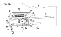
図6aは、可動の家具部分2が設置物18によってごくわずかに荷重が掛けられた、つまり一枚のプレートだけが可動の家具部分2上に位置している、家具1を示している。可動の家具部分2の下側の終端位置では、作動部材21がロック装置31からアンロックされており、作動部材21のピン27は、押圧部材9に対して相対的に離間された位置にあるので、ばね装置7は、作動アーム5に、極めて小さな回転モーメントしか及ぼさない。グリップ10を矢印37の方向に操作することによって、係止レバー17は、位置固定の軸22を中心に揺動させられ、これによって作動部材21のピン27もガイド20に沿って動かされ、ばね装置7もより軽い設置物18の重量に応じて緊縮される。ばね装置7の補償力が可動の家具部分2の重力より上回ると、可動の家具部分2は、ばね装置7の力によって上昇させられる。この上昇運動によって、切換要素33も第2の作動アーム5aから係合解除され、したがって切換要素33は、蓄力器43の力によって鉛直方向下方へ押圧され、これによって係止要素32は、係止レバー17と、作動部材21の前調整された位置でロックされる(6b参照)。可動の家具部分2の重力が小さいときには、グリップ10は、約20°の角度範囲α1内で矢印37の方向に揺動させられた。
FIG. 6a shows a
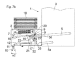
図7aおよび図7bは、可動の家具部分2が設置物18によってより重い負荷が掛けられた、つまりここでは複数のプレートが可動の家具部分2上に位置している、家具1を示している。ここでは補償力が正しく調整されてロック装置31による作動部材21の自動的なロックが惹起されるまで、グリップ10は、約40°の角度範囲内で動かさなければならない(図7b)。図7bと図6bとの直接の比較において、押圧部材9(押圧ローラの回転軸)と作動部材21のピン27との間の距離が、図7bでは(つまり可動の家具部分2の重量がより大きい場合)、図6b(可動の家具部分2の重量がより小さい)よりも小さいことが明らかである。したがって本実施の形態では、ばね装置7の、第1の作動アーム5に及ぼされる補償力は、押圧部材9と作動部材21との間の相対距離が小さいほど、より大きい。
7a and 7b show a piece of
図8は、家具駆動装置4を分解図で示している。ばね装置7は、2つのロッド40を有し、ロッド40は、2つの圧縮ばね42の座屈を防止するためにこれらの圧縮ばね42を貫通してガイドしている。軸11を中心に揺動可能なグリップ10は、プッシュレバー12と結合されており、プッシュレバー12によって、係止レバー17は、位置固定の回転軸22を中心に可動である。凸状の作動輪郭8が第1の作動アーム5に形成されており、この場合、押圧部材9は、回動可能な押圧ローラの形態で、作動輪郭8に沿って転動可能である。第2の作動アーム5aは、結合部材41を有し、結合部材41によって、第2の作動アーム5aの揺動運動は、可動の家具部分2の反対の側に配置可能な第2の作動アームの揺動運動と同期化可能である。蓄力器43も看取され、蓄力器43によって、切換要素33に、組付け状態で垂直方向下方へプリロードが掛けられている。
FIG. 8 shows the furniture drive device 4 in an exploded view. The
Claims (16)
−可動の前記家具部分(2)を動かすための、揺動可能に支持された少なくとも1つの作動アーム(5)と、
−補償装置(6)であって、該補償装置(6)は、少なくとも1つの前記作動アーム(5)に、場合によっては荷重が掛けられる前記家具部分(2)の重力とは逆向きの補償力を及ぼし、前記補償装置(6)は、少なくとも1つの前記作動アーム(5)に力を加えるためのばね装置(7)を有する、補償装置(6)と、
−少なくとも1つの前記作動アーム(5)へ前記ばね装置(7)の力を伝達するための伝達機構(19)であって、該伝達機構(19)は、可動に支持された少なくとも1つの作動部材(21)と、作動輪郭(8)と、前記ばね装置(7)により荷重が掛けられる押圧部材(9)とを有し、該押圧部材(9)は、少なくとも1つの前記作動アーム(5)の運動時に前記作動輪郭(8)に沿って走行可能である、伝達機構(19)と、
を備える、家具駆動装置において、
前記補償装置(6)は、可動の前記家具部分(2)に取り付けられるとともに人により操作されるべきグリップ(10)を有し、少なくとも1つの前記作動部材(21)は、前記グリップ(10)の操作によって、前記押圧部材(9)に対して相対的に可動であり、これによって少なくとも1つの前記作動アーム(5)に掛かる前記ばね装置(7)の力が変化可能であり、可動の前記家具部分(2)の重量が増加すると補償力が増大され、可動の前記家具部分(2)の重量が減少すると補償力が減少されることを特徴とする、家具駆動装置。 A furniture drive (4) for a furniture part (2) movably supported relative to a furniture body (3), comprising:
At least one oscillatingly supported actuating arm (5) for moving the movable furniture part (2);
A compensating device (6), said compensating device (6) compensating against at least one of said actuating arms (5) optionally against the gravity of said furniture part (2). A compensator (6) for exerting a force, said compensator (6) comprising a spring device (7) for exerting a force on at least one of said actuating arms (5);
A transmission mechanism (19) for transmitting the force of said spring device (7) to at least one said actuation arm (5), said transmission mechanism (19) being at least one actuation supported movably. It has a member (21), an actuation contour (8) and a pressing member (9) loaded by the spring device (7), said pressing member (9) being at least one of said actuating arms (5). ), the transmission mechanism (19) is capable of traveling along the operating contour (8),
In a furniture drive device, comprising:
The compensator (6) comprises a grip (10) to be mounted on the movable furniture part (2) and to be operated by a person, wherein at least one actuating member (21) comprises the grip (10). Is movable relative to the pressing member (9), whereby the force of the spring device (7) on the at least one actuating arm (5) is changeable, Furniture driving device, characterized in that the compensation force is increased when the weight of the furniture part (2) is increased, and the compensation force is decreased when the weight of the movable furniture part (2) is reduced.
Applications Claiming Priority (3)
| Application Number | Priority Date | Filing Date | Title |
|---|---|---|---|
| ATA50937/2016 | 2016-10-17 | ||
| ATA50937/2016A AT518545B1 (en) | 2016-10-17 | 2016-10-17 | furniture drive |
| PCT/AT2017/060176 WO2018071930A1 (en) | 2016-10-17 | 2017-07-13 | Furniture drive |
Publications (2)
| Publication Number | Publication Date |
|---|---|
| JP2019534760A JP2019534760A (en) | 2019-12-05 |
| JP6743298B2 true JP6743298B2 (en) | 2020-08-19 |
Family
ID=59416505
Family Applications (1)
| Application Number | Title | Priority Date | Filing Date |
|---|---|---|---|
| JP2019520559A Active JP6743298B2 (en) | 2016-10-17 | 2017-07-13 | Furniture drive |
Country Status (6)
| Country | Link |
|---|---|
| EP (1) | EP3525622B1 (en) |
| JP (1) | JP6743298B2 (en) |
| CN (1) | CN109843118B (en) |
| AT (1) | AT518545B1 (en) |
| ES (1) | ES2811356T3 (en) |
| WO (1) | WO2018071930A1 (en) |
Families Citing this family (1)
| Publication number | Priority date | Publication date | Assignee | Title |
|---|---|---|---|---|
| EP3738466B1 (en) * | 2019-05-16 | 2021-12-22 | Vauth-Sagel Holding GmbH & Co. KG | Pivoting bracket for mounting a swinging component and cabinet with such a pivoting bracket |
Family Cites Families (23)
| Publication number | Priority date | Publication date | Assignee | Title |
|---|---|---|---|---|
| US6154943A (en) * | 1994-07-16 | 2000-12-05 | Krauss; Erich | Device for closing sheathings such as cable conduits |
| AT7500U1 (en) * | 2004-02-09 | 2005-04-25 | Blum Gmbh Julius | STAND ARM DRIVE FOR FLAP FLAKES |
| HUE037072T2 (en) * | 2004-07-14 | 2018-08-28 | Blum Gmbh Julius | Piece of furniture with actuating mechanism and swivel-mounted actuating arm |
| ES2348490T3 (en) * | 2004-07-14 | 2010-12-07 | Julius Blum Gmbh | ADJUSTMENT MECHANISM FOR A PIVOT MOUNTED ADJUSTMENT ARM. |
| AT502941B1 (en) * | 2004-12-28 | 2011-05-15 | Blum Gmbh Julius | ACTUATOR FOR DRIVING A FLAP OF A FURNITURE |
| DE102005021540A1 (en) * | 2005-05-10 | 2006-11-16 | BSH Bosch und Siemens Hausgeräte GmbH | Hinge for pivoting a door to be opened to the side |
| EP1817983A1 (en) * | 2006-02-13 | 2007-08-15 | Grass GmbH | Device for influencing the movement of furniture parts moving relative to one another and a drawer guide, as well as a method of producing such a device |
| EP1820420B1 (en) * | 2006-02-16 | 2008-10-08 | Peka-Metall Ag | Built-in cupboard elements for storage |
| US7922268B2 (en) * | 2008-05-23 | 2011-04-12 | Peka-Metall Ag | Cupboard installation part with storage compartments, which part is insertable in an upper cupboard |
| AT507139A1 (en) * | 2008-07-18 | 2010-02-15 | Blum Gmbh Julius | FURNITURE DRIVE |
| AT508529A1 (en) * | 2009-07-28 | 2011-02-15 | Blum Gmbh Julius | ACTUATOR FOR A MOVABLE FURNITURE PART |
| WO2011139918A2 (en) * | 2010-05-03 | 2011-11-10 | Jonathan Roberts | System and method for an automatically adjusting force engine and assisted storage |
| AT511546B1 (en) * | 2011-05-19 | 2018-10-15 | Blum Gmbh Julius | FURNITURE DRIVE FOR A MOVABLE FURNITURE FLAP |
| CN102892274A (en) * | 2011-07-20 | 2013-01-23 | 鸿富锦精密工业(深圳)有限公司 | Installation mechanism and cabinet applying same |
| AT512919B1 (en) * | 2012-11-28 | 2013-12-15 | Blum Gmbh Julius | Device for moving a movable furniture part |
| DE102013100922A1 (en) * | 2013-01-30 | 2014-07-31 | Hettich-Heinze Gmbh & Co. Kg | Running part for guiding a furniture part in a guide direction via a guide rail and furniture fitting |
| US9980564B2 (en) * | 2013-03-15 | 2018-05-29 | Jonathan Roberts | System and method for assembling and using assisted storage |
| AT514064B1 (en) * | 2013-04-12 | 2014-10-15 | Blum Gmbh Julius | Drive device for a movable furniture part |
| AT514743B1 (en) * | 2013-09-13 | 2017-12-15 | Blum Gmbh Julius | Device for moving a furniture part |
| DE102013018498B4 (en) * | 2013-11-06 | 2016-01-07 | Kesseböhmer Holding e.K. | Pivoting tray for a piece of furniture |
| CN203913984U (en) * | 2014-05-29 | 2014-11-05 | 于维恕 | Magazine sleeve centering clutch boosting mechanism |
| CN104033043B (en) * | 2014-06-09 | 2016-03-16 | 江苏银河电子股份有限公司 | A kind of cabinet door lock and locking mechanism wherein |
| CN104912422B (en) * | 2015-06-12 | 2017-03-01 | 伍志勇 | Adjustable furniture tilt-up door damping hovering structure |
-
2016
- 2016-10-17 AT ATA50937/2016A patent/AT518545B1/en active
-
2017
- 2017-07-13 ES ES17745239T patent/ES2811356T3/en active Active
- 2017-07-13 WO PCT/AT2017/060176 patent/WO2018071930A1/en active Application Filing
- 2017-07-13 JP JP2019520559A patent/JP6743298B2/en active Active
- 2017-07-13 CN CN201780063746.9A patent/CN109843118B/en active Active
- 2017-07-13 EP EP17745239.8A patent/EP3525622B1/en active Active
Also Published As
| Publication number | Publication date |
|---|---|
| AT518545B1 (en) | 2017-11-15 |
| JP2019534760A (en) | 2019-12-05 |
| CN109843118B (en) | 2021-06-15 |
| EP3525622A1 (en) | 2019-08-21 |
| WO2018071930A1 (en) | 2018-04-26 |
| AT518545A4 (en) | 2017-11-15 |
| CN109843118A (en) | 2019-06-04 |
| EP3525622B1 (en) | 2020-05-13 |
| ES2811356T3 (en) | 2021-03-11 |
Similar Documents
| Publication | Publication Date | Title |
|---|---|---|
| JP4521444B2 (en) | Auxiliary force generator that assists force according to load | |
| JP5964457B2 (en) | Actuators for furniture flap doors | |
| JP5123164B2 (en) | furniture | |
| CN106103873B (en) | Actuation means for furniture flap | |
| JP4708005B2 (en) | Apparatus in an elevator car for temporarily connecting a cage door leaf to a hoistway door leaf and activating a cage door unlocking means | |
| US20050218264A1 (en) | Force supporting module for providing a load-dependent supporting force | |
| JP6869272B2 (en) | Actuation drive for furniture parts | |
| AU2016286281B2 (en) | Wheel drive mechanism for patient handling equipment | |
| JP6423093B2 (en) | Drive unit for movable furniture parts | |
| US20100162847A1 (en) | Actuating mechanism for a pivotably mounted actuating arm | |
| EP2784257A1 (en) | Movement system for a door or openable part of an electrical household appliance and electrical household appliance equipped with the system | |
| JPH05178569A (en) | Door driving device with latching mechanism for lift | |
| JP2015520816A (en) | Structure for operating movable furniture parts | |
| JP6743298B2 (en) | Furniture drive | |
| KR100910168B1 (en) | Heavy equipment console box of having height adjusting control device with weight balancing | |
| JP2019515162A (en) | Furniture drive | |
| JP2019525040A (en) | Lifting system for furniture doors rotating about at least one horizontal axis | |
| US9709209B2 (en) | Load support mechanism | |
| US20220213727A1 (en) | Door opening system and method | |
| JP2023549361A (en) | Furniture fittings for movably supporting furniture parts | |
| EP2986183B1 (en) | A chair adjustment device | |
| JP2000211408A (en) | Height adjustable seat | |
| JP2000262335A5 (en) | ||
| JPH072291Y2 (en) | Vehicle seat | |
| JP2008056031A (en) | Opening/closing device for gate |
Legal Events
| Date | Code | Title | Description |
|---|---|---|---|
| A621 | Written request for application examination |
Free format text: JAPANESE INTERMEDIATE CODE: A621 Effective date: 20190521 |
|
| A977 | Report on retrieval |
Free format text: JAPANESE INTERMEDIATE CODE: A971007 Effective date: 20200608 |
|
| TRDD | Decision of grant or rejection written | ||
| A01 | Written decision to grant a patent or to grant a registration (utility model) |
Free format text: JAPANESE INTERMEDIATE CODE: A01 Effective date: 20200630 |
|
| A61 | First payment of annual fees (during grant procedure) |
Free format text: JAPANESE INTERMEDIATE CODE: A61 Effective date: 20200729 |
|
| R150 | Certificate of patent or registration of utility model |
Ref document number: 6743298 Country of ref document: JP Free format text: JAPANESE INTERMEDIATE CODE: R150 |
|
| R250 | Receipt of annual fees |
Free format text: JAPANESE INTERMEDIATE CODE: R250 |