JP6742657B1 - Fixed frame for folding display panel - Google Patents

Fixed frame for folding display panel Download PDF

Info

Publication number
JP6742657B1
JP6742657B1 JP2020002634A JP2020002634A JP6742657B1 JP 6742657 B1 JP6742657 B1 JP 6742657B1 JP 2020002634 A JP2020002634 A JP 2020002634A JP 2020002634 A JP2020002634 A JP 2020002634A JP 6742657 B1 JP6742657 B1 JP 6742657B1
Authority
JP
Japan
Prior art keywords
frame
display panel
frames
divided
display panels
Prior art date
Legal status (The legal status is an assumption and is not a legal conclusion. Google has not performed a legal analysis and makes no representation as to the accuracy of the status listed.)
Active
Application number
JP2020002634A
Other languages
Japanese (ja)
Other versions
JP2021110830A (en
Inventor
昌樹 岩田
昌樹 岩田
Original Assignee
株式会社リストラ
Priority date (The priority date is an assumption and is not a legal conclusion. Google has not performed a legal analysis and makes no representation as to the accuracy of the date listed.)
Filing date
Publication date
Application filed by 株式会社リストラ filed Critical 株式会社リストラ
Priority to JP2020002634A priority Critical patent/JP6742657B1/en
Application granted granted Critical
Publication of JP6742657B1 publication Critical patent/JP6742657B1/en
Publication of JP2021110830A publication Critical patent/JP2021110830A/en
Active legal-status Critical Current
Anticipated expiration legal-status Critical

Links

Images

Landscapes

  • Road Signs Or Road Markings (AREA)

Abstract

【課題】折畳むことにより取扱いが便利で安全な通行表示パネルを提供する。
【解決手段】この発明は、表面側に表示パネル14を取付ける枠体1と枠体1を床面上で起立姿勢で支持するスタンド7とを備えた表示パネル用固定枠であって、枠体1を2個以上に分割して形成し、分割された分割枠2,3毎に各別の表示パネル14,16を取付けるとともに分割枠2,3間に表示パネル14,16の表示面を内向き方向に折畳み開閉可能なヒンジ部4を設け、隣接する分割枠2,3同士は、展開した表示姿勢で係脱可能に固定する。
【選択図】図1
PROBLEM TO BE SOLVED: To provide a traffic display panel which is convenient to handle by folding and is safe.
The present invention is a fixed frame for a display panel, comprising a frame body 1 for mounting a display panel 14 on a front surface side thereof, and a stand 7 for supporting the frame body 1 in a standing posture on a floor surface. 1 is divided into two or more parts, and separate display panels 14 and 16 are attached to each of the divided frames 2 and 3, and the display surfaces of the display panels 14 and 16 are inserted between the divided frames 2 and 3. A hinge portion 4 that can be folded and opened in the direction is provided, and the adjacent divided frames 2 and 3 are detachably fixed in the expanded display posture.
[Selection diagram] Figure 1

Description

この発明は主として高速道路や一般道その他のガスや水道工事現場又は各種イベント会場等において通行案内標識に使用される折畳み式表示パネル用固定枠に関する。 The present invention relates mainly to a fixed frame for a folding display panel used as a traffic sign at a highway, a general road, gas and waterworks construction sites, various event sites, and the like.

従来上記のような建設現場やイベント会場では、特許文献1に示すような折畳み可能なスタンドが折畳みできる立看板式の表示具が知られており、この立看板は現場の人や車両等の通行量が多い場合又はダンプカーやコンテナカー等のドライバーのように高い運転席から瞬時に表示内容を視認する必要から、例えば枠幅900〜1400mm,高さ1400〜1800mm程度の高くて幅広の看板が求められることが多い。そしてこれにスタンド部分の高さがプラスされるとさらに高さが必要となる。 Conventionally, in the construction sites and event venues as described above, there is known a display device of a standing signboard type in which a foldable stand as shown in Patent Document 1 can be folded. When there is a large amount or because it is necessary to instantly see the displayed contents from a high driver's seat such as a driver of a dump truck or a container car, for example, a high and wide signboard with a frame width of 900 to 1400 mm and a height of 1400 to 1800 mm is required. It is often done. And if the height of the stand portion is added to this, a further height is required.

特許第6141219号公報Japanese Patent No. 6141219

しかし上記のような大型の看板はドライバーや通行人等にとって視認性には優れているものの、表示パネルを固定する枠体サイズは、例えば展示現場に搬送する際も軽自動車やパトロールカー等のサイズでは積み込み自体が難しくダンプカーや大型トラックを必要とするケースも少なくなく、重量もあるため作業者も複数人を要することが多い。 However, although the large signboards described above are highly visible to drivers and passersby, the frame size for fixing the display panel is, for example, the size of a light vehicle or patrol car when transported to an exhibition site. In many cases, it is difficult to load the cargo itself and a dump truck or a large truck is required. Since it is heavy, it often requires a plurality of workers.

また大型看板は現場で設置場所まで持ち運ぶ際も、看板を背面から視界不良のまま把持して横歩き状態で搬送する必要が多く、通行する人への接触や走行中の車両への接触等の危険性も高く作業効率も悪い等の欠点がある。特に足場の悪く又は強風下の工事現場での転倒や高速道路の大型車両の風圧を受ける事故の懸念がある。 In addition, even when carrying large signboards to the installation site on site, it is often necessary to grip the signboard from the back with poor visibility and carry it while walking sideways, such as contact with people passing by or contact with moving vehicles. There are drawbacks such as high risk and poor work efficiency. In particular, there is a risk of accidents such as falls at construction sites with bad footing or strong winds and the wind pressure of large vehicles on highways.

上記課題を解決するための本発明の表示パネル用固定枠は、第1に表面側に表示パネル14を取付ける枠体1と枠体1を床面上の背面側で起立姿勢で支持するスタンド7とを備えた表示パネル用固定枠であって、枠体1を2個以上に分割して形成し、分割された分割枠2,3毎に各別の表示パネル14,16を取付けるとともに分割枠2,3間に表示パネル14,16の表示面を内向き方向に折畳み開閉可能なヒンジ部4を設け、表示パネル14,16を収容した隣接する分割枠2,3同士を折畳んだ姿勢の枠体1の上端側に突出し、枠体1全体を持運び可能に把持する横杆からなる把持部7aを設け、該把持部7aが上記スタンド7の一部を構成し、折畳み状態で上辺側で横方向に架設される1本又は2本以上の横杆であることを特徴としている。 A fixed frame for a display panel according to the present invention for solving the above-mentioned problems is, firstly, a frame 1 for mounting a display panel 14 on the front surface side and a stand 7 for supporting the frame body 1 in a standing posture on the back side on the floor. A fixed frame for a display panel, comprising: a frame body 1 formed by dividing the frame body 1 into two or more, and attaching separate display panels 14 and 16 to each of the divided division frames 2 and 3; Between the display panels 2 and 3, the display surfaces of the display panels 14 and 16 are folded inward, and a hinge portion 4 that can be opened and closed is provided , and the adjacent division frames 2 and 3 accommodating the display panels 14 and 16 are folded. The frame 1 is provided with a grip portion 7a which is a lateral rod for gripping the entire frame body 1 so as to be able to carry the whole frame body 1. The grip portion 7a constitutes a part of the stand 7, and the upper side in the folded state. It is characterized in that it is one or two or more horizontal rods installed in the horizontal direction .

第2に、隣接する分割枠2,3同士を、展開した表示姿勢で係脱可能に固定するクランプ機構を設けたことを特徴としている。 Secondly, the present invention is characterized in that a clamp mechanism is provided for fixing the adjacent divided frames 2 and 3 to each other so that they can be engaged and disengaged in the expanded display posture.

に、隣接する分割枠2,3同士を伸展させた突合せ状態で、一方の分割枠2を他方の分割枠3に沿わせて保持するサポート杆6をいずれかの分割枠に取付けてなることを特徴としている。 Third, butting state of division frame 2,3 is extended to the adjacent, comprising a support rod 6 for holding and along one of the divided frame 2 on the other divided frame 3 attached to one of the divided frame It is characterized by that.

に、隣接する分割枠2,3の少なくとも両端の枠材2a,2bをパイプ材とし、該枠材2a,2bの突合せ状態で一方のパイプ材の開口部から突出させ他方のパイプ材に挿脱可能に差込むことにより隣接する分割枠2,3を伸展状態で保持するサポート杆6を設けてなることを特徴としている。 Fourth , at least the frame members 2a and 2b at both ends of the adjacent divided frames 2 and 3 are used as pipe members, and when the frame members 2a and 2b are abutted with each other, the pipe members are projected from the opening of one pipe member to the other pipe member. It is characterized in that it is provided with a support rod 6 which holds the adjacent divided frames 2 and 3 in an extended state by inserting them so that they can be inserted and removed.

に、四角形の分割枠2,3の四辺の枠材2a,2b,2c,2dの内少なくとも相対する2辺の枠材に対して表示パネル14,16を表面側から着脱可能に押接固定する押えカバー17を設けたことを特徴としている。 The 5, the frame member 2a of the four sides of the rectangular split frames 2,3, 2b, 2c, 2d of detachably display panels 14 and 16 from the front side to at least two opposite sides of the frame member pressed against It is characterized in that a pressing cover 17 for fixing is provided.

に、隣接する一方の分割枠2と他方の分割枠3の境界部に設けたヒンジ部4を枠体伸展時に枠体1の表面に突出させる機構とし、該突出したヒンジ部4に表示パネル14,16の隣接端を当接させて表示パネル14,16の位置決めを行うことを特徴としている。 Sixth , the hinge portion 4 provided at the boundary between the adjacent one of the divided frames 2 and the other divided frame 3 is a mechanism for projecting to the surface of the frame body 1 when the frame body is extended, and is displayed on the projected hinge portion 4. The display panels 14 and 16 are positioned by bringing adjacent ends of the panels 14 and 16 into contact with each other.

に、枠体1内に取付けられた表示パネル14,16間に、枠体1の前後一方の側から他方の側を透視できる窓状の透視空間27を形成してなることを特徴としている。 Seventh , a window-shaped transparent space 27 is formed between the display panels 14 and 16 mounted in the frame 1 so that the front and rear sides of the frame 1 can be seen through from the other side. There is.

本発明のパネル用固定枠は以上のように構成されるので、以下のような効果を奏する。
(1)枠体が2個以上の折畳み可能な分割枠で構成されるため、表示パネルの高さと幅をより大きくした大型看板であっても、折畳み状態で持運びや荷積みが出来るので、横歩きや視界不良状態もなくこれらの作業効率が良く、他の通行者や作業者自身の安全性の確保ができるとともに作業効率が向上する。
また1つの枠体で複数の表示パネルの展示ができ、展示内容も多彩になり、通行人や作業者の安全性を確保できる利点がある。特に隣接分割枠間に空間を形成できるので、この空間を介して看板の反対側の現場情況の視認ができる等の効果を得ることができる。
Since the panel fixing frame of the present invention is configured as described above, it has the following effects.
(1) Since the frame body is composed of two or more foldable split frames, even a large signboard with a larger display panel height and width can be carried and loaded in a folded state. The work efficiency is good without sidewalking and poor visibility, the safety of other passersby and the worker himself can be secured, and the work efficiency is improved.
In addition, a plurality of display panels can be displayed in one frame, and the contents of the display can be diversified, which is advantageous in that the safety of passers-by and workers can be secured. In particular, since a space can be formed between the adjacent divided frames, it is possible to obtain an effect that the situation of the site on the opposite side of the signboard can be visually recognized through this space.

(2)折畳み状態をクランプ機構でセットし、枠体の横杆等を把持部として簡単に持運びや積荷作業が安全を確保しながら行えるほか、枠体の分割枠に表示パネルを押接固定する押えカバーを設け、隣接分割パネルは互に内向きに折畳まれるので、高輝度表示パネル等の高価なパネルであっても、積重ねや搬送時に表面を損傷することがなく、長寿命を保てるほか、上下とも表示内容を自由に選択し、多用途に使用できる。
上記以外の本発明の効果及び詳細な特徴は、[発明を実施するための形態]の項において説明する。
(2) The folded state is set by the clamp mechanism, and the horizontal rod of the frame can be used as a grip part to easily carry and load while ensuring safety, and the display panel is fixed by pressing on the divided frame of the frame. Adjacent split panels are folded inward with respect to each other, so even expensive panels such as high-brightness display panels do not damage the surface during stacking and transportation, and have a long life. In addition to being able to keep it, you can freely select the display contents of the upper and lower sides and use it for various purposes.
The effects and detailed features of the present invention other than the above will be described in the section of [Mode for carrying out the invention].

本発明の一実施形態を示す看板のスタンド状態の全体斜視図である。It is the whole stand perspective view of the signboard which shows one embodiment of the present invention. 同じく看板の折畳み状態を示す側断面図である。Similarly, it is a side sectional view showing a folded state of the signboard. 枠体の折畳み状態におけるクランプ機構及びサポート機構を示す側断面拡大図である。FIG. 7 is an enlarged side cross-sectional view showing the clamp mechanism and the support mechanism in a folded state of the frame body. 枠体の枠材による表示パネルの押接固定機構を示す部分拡大断面図である。FIG. 7 is a partially enlarged cross-sectional view showing a pressing and fixing mechanism of a display panel by a frame material of a frame body. 枠体の折畳み状態における上端の平面図である。It is a top view of the upper end in the folded state of a frame. 2番目の実施形態を示す看板のスタンド状態の正面全体図である。It is the front whole front view of the stand state of the signboard which shows a 2nd embodiment. 同じく第2実施形態の折畳み状態を示す側断面図である。Similarly, it is a side sectional view showing a folded state of the second embodiment. 枠体の伸展状態のクランプ機構及びサポート機構を示す拡大側面断面図である。FIG. 6 is an enlarged side cross-sectional view showing a clamp mechanism and a support mechanism in a stretched state of the frame body. (A),(B)は共に本発明の看板における表示板間に透視空間を設けた例を示す正面図である。(A) And (B) is a front view which shows the example which provided the see-through space between the display boards in the signboard of this invention.

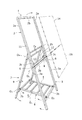
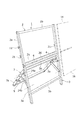
図1〜図4はこの発明の第1実施形態を示し、図1は本発明の折畳み式の表示パネル用固定枠の全体斜視図を示し、枠体1はこの例では設置高さ1500mm,幅600mm程度で、管径20〜25mm程度のアルミ押出成形材で縦長の長方形に形成されている。枠体1は略中間位置で上下の分割枠2,3として分割形成され、上分割枠2と下分割枠3はそれぞれ縦長の長方形に形成され、左右の縦枠材2a,3aと上下端の横枠材2b,3bで組立構成されている。下分割枠3の縦枠材3aの下端は下枠材3bより突出して接地用の脚部を兼ねている。 1 to 4 show a first embodiment of the present invention, and FIG. 1 shows an overall perspective view of a foldable display panel fixing frame according to the present invention. The frame body 1 in this example has an installation height of 1500 mm and a width. It is about 600 mm, and is formed into a vertically long rectangle with an aluminum extrusion molding material having a tube diameter of about 20 to 25 mm. The frame body 1 is divided and formed into upper and lower divided frames 2 and 3 at a substantially intermediate position, and the upper divided frame 2 and the lower divided frame 3 are formed into vertically long rectangles, and the left and right vertical frame members 2a and 3a and the upper and lower end portions are formed. The horizontal frame members 2b and 3b are assembled and configured. The lower end of the vertical frame member 3a of the lower split frame 3 projects from the lower frame member 3b and also serves as a leg for grounding.

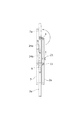
上下の分割枠2,3の隣接横枠材2b,3bは左右のヒンジ部4を介して連結され、正面(表示面)側を内向きにして折畳んで重ね合わされる機構となっており(図2参照)、下分割枠3の上端側背面には、図示するように、上分枠枠2で伸展された起立状態で、上分割枠2の左右の縦枠材2aの下端側背面を受け止めて支持するアングル状断面のサポート杆6が上側に突出させて取付けられている。 Adjacent horizontal frame members 2b and 3b of the upper and lower split frames 2 and 3 are connected to each other via left and right hinges 4 and are folded and stacked with the front (display surface) side facing inward ( (See FIG. 2), on the upper back surface of the lower split frame 3, as shown in the drawing, the lower back surfaces of the left and right vertical frame members 2a of the upper split frame 2 in a standing state extended by the upper split frame 2. A support rod 6 having an angled cross section for receiving and supporting is attached so as to project upward.

上記左右のサポート杆6の上端内面側には、長方形枠からなるスタンド7の上端がそれぞれ回動開閉可能に連結されて取付けられており、その下端側の横杆7bと下分割枠3の下端側の横枠材3bとの間には、中間部で屈伸して折畳み回動可能な梯子状の位置決め枠8が連結して取付けられている。位置決め枠8は伸展状態でスタンドの開脚を固定的にセットされ、その上面にウェイトを載置して安定的起立状態を保持させる。 On the inner surfaces of the upper ends of the left and
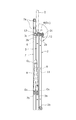
 right support rods 6, an upper end of a stand 7 formed of a rectangular frame is attached so as to be rotatable and openable, and a horizontal rod 7b on the lower end side and a lower end of the lower split frame 3 are attached. A positioning frame 8 in the form of a ladder, which is bent and stretched at an intermediate portion and is foldable and rotatable, is connected to and attached to the side horizontal frame member 3b. The positioning frame 8 is fixed to the open leg of the stand in the extended state, and a weight is placed on the upper surface of the positioning frame 8 to maintain a stable standing state.

上記機構により、位置決め枠8の中央と前後両端の連結支点O〜Oの内、中央の連結支点Oを上向きに操作することにより、スタンド7の上端の連結支点Oを支点にスタンド7が枠体1の背面に沿って折畳まれる。また上下の分割枠2,3は両者のヒンジ部4の連結支点Oを介して正面(表示面)側の内側にして図2のように折畳むことができる。 By the mechanism, of the connecting fulcrum O 1 ~ O 3 in the central and front and rear ends of the positioning frame 8, by operating upwardly the connecting fulcrum O 1 of the center stand the connecting fulcrum O 4 of the upper end of the stand 7 as a fulcrum 7 is folded along the back surface of the frame 1. Further, the upper and lower dividing frames 2 and 3 can be folded inside as shown in FIG. 2 so as to be inside the front surface (display surface) via the connecting fulcrum O 5 of the hinge portions 4 of both.

この折畳み状態をセットするために、スタンド7の側面には係止用のフック材9が回動自在に付設され、上分割枠2の同側面対応位置には、折畳み状態で係止用のフック材9に係脱可能に係止される蝶ねじ等からなる係止ボルト11が設けられ、係止ボルト11を締付けることにより、固定枠全体が折畳み状態でセットされる。 In order to set this folded state, a hook material 9 for locking is rotatably attached to the side surface of the stand 7, and the hook for locking is held at the position corresponding to the same side of the upper split frame 2 in the folded state. A locking bolt 11 such as a thumbscrew that is removably locked to the material 9 is provided, and by tightening the locking bolt 11, the entire fixing frame is set in a folded state.

またスタンド7の上端側には図2に示す折畳み状態で、持運び用の把手となる2本の横杆7aが所定間隔を介して設けられており、このように折畳んだ状態で作業者が上端側を把持して持ち運ぶことが可能なので、大型看板を左右両側から抱えて視界を遮られながら横歩きしなければならない等の不便は解消され、倉庫や車両での荷積、荷降しも容易になる。 Further, in the folded state shown in FIG. 2, two horizontal rods 7a, which are handles for carrying, are provided at a predetermined interval on the upper end side of the stand 7, and the operator in the folded state in this way Since it can be carried while grasping the upper end side, the inconvenience of having to walk sideways while holding a large signboard from both left and right sides while obstructing the view is eliminated, loading and unloading in warehouses and vehicles Will also be easier.

前記上下の分割枠2,3の伸展状態の保持は、前述したサポート杆6で上分割枠2を下分割枠3に沿って支えるほか、次のようなクランプ機構により固定的にセットされて保持される。 In order to hold the upper and lower split frames 2 and 3 in the extended state, in addition to supporting the upper split frame 2 along the lower split frame 3 by the support rod 6 described above, the upper and lower split frames 2 are fixedly set and held by the following clamp mechanism. To be done.

枠体1の上下の中間位置において上下の分割枠2,3の突合せ端で隣接し合う横枠材2b,3bをボルト締着するもので、図1〜図3で示すように伸展状態で上下向き合って隣接する上下の横枠材2b,3bの背面側の左右2箇所の対応位置には、それぞれ一対のブラケット2c,3cが上下に対向するように取付けられ、一方(上方)のブラケット2cに蝶ねじ等からなるボルト12の先端を下向きに突出させて回動自在に保持し、他方(下方)のブラケット3cに上記ボルト12をねじ込むクリンプナット等よりなるナット部13を設け、両ブラケット2c,3cを上下より締着固定する。このようにブラケット2c,3cをボルト締着することにより、上分割枠2と下分割枠3は同一平面上で一体的に連結されてクランプされる。 The horizontal frame members 2b and 3b that are adjacent to each other at the abutting ends of the upper and lower split frames 2 and 3 are bolted at the upper and lower intermediate positions of the frame body 1, and are vertically extended in the extended state as shown in FIGS. A pair of brackets 2c and 3c are attached so as to vertically face each other at corresponding positions on the right and left sides on the back side of the upper and lower horizontal frame members 2b and 3b which are opposed to each other, and are attached to one (upper) bracket 2c. The tip of a bolt 12 made of a thumbscrew or the like is projected downward to hold it rotatably, and the other (lower) bracket 3c is provided with a nut portion 13 made of a crimp nut or the like into which the bolt 12 is screwed. Fix 3c from above and below. By bolting the brackets 2c and 3c in this manner, the upper divided frame 2 and the lower divided frame 3 are integrally connected and clamped on the same plane.

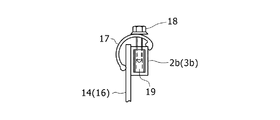
次に各分割枠2,3に対する表示パネル14,16の取付固定機構について説明すると、枠体1の上下左右端の枠材2b,3b,2a,3aにおいては図4,図5に示すように各枠材共に長方形(正方形でも可)の枠材2a,2b,3a,3bの表面に表示パネル14,16を沿わせて枠内に収容し、その表面側からC型断面のアルミ製品からなる押えカバー17の一端で着脱自在に押接固定している。 Next, the mounting and fixing mechanism of the display panels 14 and 16 with respect to the respective divided frames 2 and 3 will be described. As shown in FIGS. Each of the frame members is a rectangular (or square) frame member 2a, 2b, 3a, 3b, and the display panels 14, 16 are arranged on the surface of the frame member and housed in the frame. One end of the presser cover 17 is detachably pressed and fixed.

この機構は既述の特許文献1中の図2で示される公知のものであるが、この例では長方形断面のパイプ材からなる枠材2a,2b,3a,3bの背面外側コーナーに押えカバー17の一端を位置決め係止し、他方の端部を枠材の表面側に沿って配置された表示パネル14,16の表面に押接固定するものであり、この押接は押えカバー17をその外側からボルト18で、枠材2a,2b,3a,3b内のクリンプナットからなるナット部19にねじ込んで締着固定するものである。 This mechanism is a known one shown in FIG. 2 of the above-mentioned Patent Document 1, but in this example, the pressing cover 17 is attached to the rear outer corners of the frame members 2a, 2b, 3a, 3b made of a pipe material having a rectangular cross section. Is positioned and locked at one end, and the other end is pressed and fixed to the surfaces of the display panels 14 and 16 arranged along the front surface side of the frame member. The bolts 18 are screwed into the nut portions 19 made of crimp nuts in the frame members 2a, 2b, 3a, 3b for fastening and fixing.

他方、この例では上下の分割枠2,3はヒンジ部4で連結されており、表示パネル14,16の下端と上端は表面側に突出したヒンジ部4に当接して位置決めされ、隣接し合う枠体1の中間の枠材2b,3bには押えカバー17は設けられていない。即ち上下の表示パネル14,16の隣接端は固定されず、枠体1の上下の横枠材2b,3bと左右の縦枠材2a,3aでのみ押えカバー17によって取付固定されている。 On the other hand, in this example, the upper and lower dividing frames 2 and 3 are connected by a hinge portion 4, and the lower and upper ends of the display panels 14 and 16 are brought into contact with the hinge portion 4 protruding toward the front side to be positioned and adjacent to each other. The pressing cover 17 is not provided on the frame members 2b and 3b in the middle of the frame body 1. That is, the adjacent ends of the upper and lower display panels 14 and 16 are not fixed, but are attached and fixed by the presser cover 17 only to the upper and lower horizontal frame members 2b and 3b and the left and right vertical frame members 2a and 3a.

上記のような表示パネル14,16の固定構造により、上下の分割枠2,3を折畳んで重ね合わせた時、押えカバー17同士が当接し合い、表示パネル14,16の表面には何も接触しないため、表示パネル表面の損傷が防止され、表示パネル14,16は繰返し再利用でき、経済性が良い。また押えカバー17による固定なので、表示パネル14,16は、押えカバー17の損傷端の開き幅の範囲で厚みに制約されることはないし、押えカバー17によって損傷し易い表示パネル14,16の外周縁は常に保護される利点がある。 Due to the fixing structure of the display panels 14 and 16 as described above, when the upper and lower split frames 2 and 3 are folded and overlapped, the presser covers 17 are brought into contact with each other, and nothing is displayed on the surfaces of the display panels 14 and 16. Since they do not come into contact with each other, the display panel surface is prevented from being damaged, and the display panels 14 and 16 can be reused repeatedly, which is economical. Further, since the presser cover 17 is used for fixing, the display panels 14 and 16 are not restricted in thickness within the range of the opening width of the damaged end of the presser cover 17, and the display panels 14 and 16 are easily damaged by the presser cover 17. The perimeter has the advantage of always being protected.

上記枠体1,スタンド7,位置決め枠8等の長方形枠の枠部材や格子部分は、いずれも溶接固定を避け、ビス止め等により組立分解可能に構成されている。 The frame members such as the frame body 1, the stand 7, the positioning frame 8 and the like, and the lattice portion of the rectangular frame are constructed so as to be assembled and disassembled by screwing or the like, avoiding welding fixation.

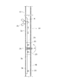
図6〜図8はこの発明の第2実施形態を示し、この例では、枠体1を構成する上下の分割枠2,3の四辺の枠材2a,2b,3a,3bがすべて四角形(正方形)断面のアルミ製押出材からなるパイプを用いており、いずれの枠材にも押えカバー17を設けず、同一平面の上下の分割枠2,3の表面に、直接上下表示パネル14,16をテックスビス等によって直接貼付け固定するタイプのものを示している。この場合も上下表示パネル14,16は上下分割枠2,3を連結するヒンジ部4を介して位置決め状態で突合わされる。 6 to 8 show a second embodiment of the present invention, and in this example, the frame members 2a, 2b, 3a, 3b on the four sides of the upper and lower dividing frames 2 and 3 which form the frame body 1 are all quadrangles (squares). ) A pipe made of aluminum extruded material with a cross section is used, and the presser covers 17 are not provided on any of the frame members, and the upper and lower display panels 14 and 16 are directly attached to the surfaces of the upper and lower split frames 2 and 3 on the same plane. Shown is a type that is directly attached and fixed with Tex screw or the like. Also in this case, the upper and lower display panels 14 and 16 are butted in a positioned state via the hinge portion 4 that connects the upper and lower divided frames 2 and 3.

また本例のクランプ機構では、展開(伸展)姿勢の上下分枠枠2,3の両側の縦枠材2a,3aの突合せ端に、各1本の帯板状又は棒状のサポート杆6を挿脱自在に差込むことによって、上下分割枠2,3を伸展姿勢で保持させている。 Further, in the clamp mechanism of this example, one strip-shaped or rod-shaped support rod 6 is inserted at the abutting ends of the vertical frame members 2a and 3a on both sides of the upper and lower split frame frames 2 and 3 in the expanded (extended) posture. The upper and lower split frames 2 and 3 are held in an extended posture by being freely inserted.

そしてこの例ではサポート杆6は上端を上側の左右の縦枠材2aの下端側に挿入するとともに、縦枠材2aの背面側の周壁に形成した縦方向の長孔22よりサポート杆6にボルト(蝶ねじ)21をねじ込んで上下スライドの範囲を決めて保持している。 In this example, the upper end of the support rod 6 is inserted into the lower end of the upper left and right vertical frame members 2a, and the support rod 6 is bolted to the support rod 6 through the longitudinal elongated hole 22 formed in the peripheral wall on the rear side of the vertical frame member 2a. (Thumbscrew) 21 is screwed in to determine the vertical slide range and hold it.

該サポート杆6の下端は下降スライド状態で所定長さ縦枠材2aの下端より突出し、この姿勢で下側の縦枠材3aの上部開口端に差込み挿入されて上下の縦枠材2a,3aは接続され、一直線上に接合される。サポート杆6の先端は縦枠材2a,3aの背面周壁内面と内部に左右方向に挿通されたボルト等のピン材23との間に挿入されて上下の縦枠材2a,3aの通直姿勢を保持する。 The lower end of the support rod 6 projects downward from the lower end of the vertical frame member 2a of a predetermined length in the descending slide state, and in this posture, the lower end of the vertical frame member 3a is inserted and inserted into the upper and lower vertical frame members 2a, 3a. Are connected and joined in a straight line. The tip of the support rod 6 is inserted between the inner surface of the rear peripheral wall of the vertical frame members 2a and 3a and the pin member 23 such as a bolt inserted in the left and right direction inside, and the vertical postures of the upper and lower vertical frame members 2a and 3a are straightened. Hold.

上記サポート杆6は格納状態(枠体の折畳み時)も、上下分割枠2,3を展開した伸展状態の時も、蝶ねじを締付けることによって上下の位置決めセットが行われる。さらにこの例では、左右のヒンジ部4,4の間の下分割枠3の横枠材3b上に、板状のスペーサー26を沿わせて取付けており、上分割枠2が起立した時に、その下辺の横枠材3bに当接して十分に支えられる機構になっている。 The support rod 6 can be set up and down by tightening the thumbscrews both in the retracted state (when the frame is folded) and in the extended state where the upper and lower split frames 2 and 3 are expanded. Further, in this example, a plate-like spacer 26 is attached along the horizontal frame member 3b of the lower split frame 3 between the left and right hinge portions 4 and 4, and when the upper split frame 2 stands up, The mechanism is in contact with the horizontal frame member 3b on the lower side and is sufficiently supported.

またこの実施形態では図6,図7に示すように、背面側に折畳み開閉可能に設けた枠状のスタンド7はスタンド7の左右の縦杆7bと下分割枠3の縦枠材3aとの間を連結する上下のリンク24a,24bによって取付けられている。このタイプのものは看板設置時の高さが約80cm程度と低いために、スタンド7の上端は下分割枠3の上端側背面に当接してスタンド姿勢をサポートする機構となっている。 Further, in this embodiment, as shown in FIGS. 6 and 7, the frame-shaped stand 7 provided on the back side so as to be openable and closable includes a vertical rod 7b on the left and right of the stand 7 and a vertical frame member 3a of the lower split frame 3. It is attached by upper and lower links 24a and 24b that connect the two. Since the height of this type when the signboard is installed is as low as about 80 cm, the upper end of the stand 7 is in contact with the rear surface of the lower split frame 3 on the upper end side to support the stand posture.

そしてスタンド7の上端には折畳み時の持運び用の把手となる横杆7aを備えている。上記以外の機械的構成は前記第1実施形態と共通し、共通機能部分は符号も共通の符号で示されているので詳細な説明は省略する。 The stand 7 is provided at its upper end with a horizontal rod 7a which serves as a handle for carrying when folded. The mechanical configuration other than the above is common to that of the first embodiment, and common functional portions are designated by common reference numerals, and therefore detailed description thereof will be omitted.

上記実施形態ではいずれも分割枠は上下2段としたが、これを3段以上に分割すること又は分割枠間に空間を設け、設置時に背面側の視界を確保することにより用途や設置場所の安全性を高めることも可能である。その他上下方向の分割枠以外に横方向の分割枠を連結し、持運びを簡単にすることもできる。 In each of the above-described embodiments, the dividing frame has two upper and lower stages, but by dividing this into three or more stages or by providing a space between the dividing frames and ensuring a view on the rear side at the time of installation, the use and installation location can be improved. It is also possible to increase safety. In addition to the vertical dividing frame, the horizontal dividing frame can be connected to facilitate carrying.

尚、本発明のように枠体表示面を複数に分割することにより、一個の枠体内に内容の異なる、あるいは一内容を補充する補充的な表示を行う複数種のパネルを取付けることができる。 By dividing the frame body display surface into a plurality of frames as in the present invention, it is possible to mount a plurality of types of panels having different contents or supplementary displays for supplementing one content in one frame body.

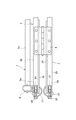
図9(A)(B)はいずれも上記図1〜図5に示す枠体1内の複数の表示パネル14,16間に表示パネルのない透視空間27を形成した実施形態を示している。図9(A)は上下の分割枠2,3の隣接端側に、一定の上下間隔を介して横枠材2b´,3b´をそれぞれ横設し、各横枠材2b,2´間、横枠材3b,3b´間にそれぞれ形成された横長の長方形空間が透視空間27として形成したものを示している。 9A and 9B each show an embodiment in which a transparent space 27 having no display panel is formed between the plurality of display panels 14 and 16 in the frame body 1 shown in FIGS. In FIG. 9(A), horizontal frame members 2b' and 3b' are horizontally installed on the adjacent end sides of the upper and lower split frames 2 and 3 with a constant vertical interval, and between the horizontal frame members 2b and 2', A horizontally long rectangular space formed between the horizontal frame members 3b and 3b' is formed as the perspective space 27.

図9(B)では、上記のような横枠材2b´,3b´を設けることなく、上下の分割枠2,3内で保持される表示パネル自体を互に表示内容の異なる上表示パネル14a,14b、下表示パネル16a,16bにそれぞれ上下に分割形成し、各表示パネル14a,14b間及び16a,16b間に透視空間27をそれぞれ介設形成して各表示パネル14a,14b,16a,16bを押接(挟持)して固定している。表示パネル14,16の固定方法は異なるものの、上記実施形態はいずれも図6〜図8の実施形態にも応用可能である。 In FIG. 9(B), the display panels themselves held in the upper and lower split frames 2 and 3 do not have the horizontal frame members 2b′ and 3b′ as described above, but the upper display panel 14a having different display contents from each other. , 14b and the lower display panels 16a, 16b are divided into upper and lower parts, respectively, and a transparent space 27 is formed between the respective display panels 14a, 14b and 16a, 16b to form the respective display panels 14a, 14b, 16a, 16b. Is fixed by pressing (sandwiching). Although the method of fixing the display panels 14 and 16 is different, any of the above embodiments can be applied to the embodiments of FIGS. 6 to 8.

上記透視空間27は、枠体1を伸展させた設置(展示)形態においては、通行するドライバーや通行人、現場作業者等が枠体1の反対側の現場情況を見透して安全確認ができる利点があるほか、枠体1の設置現場で小移動のために枠体1を持ち運ぶ際の枠体反対側の視界確保ができる。 In the above-mentioned perspective space 27, in the installed (exhibited) form in which the frame body 1 is extended, a driver, a passerby, a site worker, etc. who pass by can see through the situation on the opposite side of the frame body 1 and confirm the safety. In addition to the advantages that can be obtained, it is possible to secure the field of view on the opposite side of the frame body 1 when carrying the frame body 1 for small movement at the installation site of the frame body 1.

また上記透視空間27は設置現場においては、強風や大型車両通過時のあおり風等の風圧に対しても、風を通過させることによって枠体全体が受ける風圧を低減できるので、有効な通風空間としても作用する。 Further, the above-mentioned perspective space 27 is an effective ventilation space because it can reduce the wind pressure received by the entire frame by passing wind even against wind pressure such as strong wind or flapping wind when passing a large vehicle at the installation site. Also works.

以上説明した本発明の実施形態における詳細な特徴を重ねて説明すると以下の通りである。
(1)従来一般に普及しているスタンド式看板は、長方形の枠体に表示パネルを一体的に取付けたものに、折畳みスタンドを取付けたものである。これに対し本発明の図1〜図5に示す固定枠は、枠体1自体を2つ折りに折畳み可能に上下分割形成し、各分割枠2,3に表示パネル14,16を挿脱可能に取付けており、背面側に長方形枠からなるスタンド7を折畳み可能に取付けている。
The detailed features of the embodiment of the present invention described above will be described below.
(1) A conventional stand-type signboard has a rectangular frame body to which a display panel is integrally attached, and a folding stand to which is attached. On the other hand, in the fixed frame shown in FIGS. 1 to 5 of the present invention, the frame body 1 itself is divided into upper and lower parts so as to be foldable, and the display panels 14 and 16 can be inserted into and removed from the respective divided frames 2 and 3. It is attached, and a stand 7 composed of a rectangular frame is attached to the back side so as to be foldable.

このスタンド7は下分割枠3の連結端背面に上向きに突設され、上分割枠2を伸展状態で支えるサポート杆6の上端に折畳み回動可能に連結されている。そして上記スタンド7上端側の横杆7aを枠体折畳み状態での把持部としている。 The stand 7 is provided so as to project upward on the rear surface of the connection end of the lower split frame 3, and is foldably and rotatably connected to the upper end of a support rod 6 that supports the upper split frame 2 in an extended state. The horizontal rod 7a on the upper end side of the stand 7 serves as a grip portion in the folded state of the frame body.

このため、枠体1は折畳まれて約1/2の高さとなった状態で上記横杆7aを把手として作業者が持運びでき、両手に1枠又は2枠同時に持ち運びできる。 Therefore, an operator can carry the frame 1 with the horizontal rod 7a as a handle in a state where the frame 1 is folded and has a height of about 1/2, and one frame or two frames can be carried in both hands at the same time.

(2)従来大型看板搬送には大型車両の使用が必要であったが、折畳み式にすることによりパトロールカー等の普通乗用車のトランクや軽自動車等への搭載も可能となり、交通事故や自然災害、その他の緊急の車両止め等緊急時の案内表示も迅速対応が可能となる。 (2) Conventionally, it was necessary to use a large vehicle for transporting large signboards, but by making it a foldable type, it becomes possible to install it in the trunk of a normal passenger car such as a patrol car or a light vehicle, which will cause a traffic accident or natural disaster. In addition, it is possible to promptly respond to emergency guidance displays such as other emergency vehicle stops.

(3)一般に通行表示板による案内表示には、工事現場の場合施工会社,工事内容,区間,日程,施工者等を記載するが、その役割は当該工事の終了をもって終了し、表示パネル自体は消耗品として1回限りの使用で廃棄されるが、表示パネルを挿脱交換可能とし、異なる種類の表示項目毎に分割して準備することにより、表示パネル自体を耐久材として繰り返し利用することができる。 (3) Generally, in the case of a construction site, the construction company, construction content, section, schedule, and construction person are described in the guidance display on the traffic display board, but the role ends when the construction is completed, and the display panel itself Although it is discarded as a consumable item only once, the display panel can be inserted and removed and replaced, and the display panel itself can be used repeatedly as a durable material by preparing separately for each different type of display item. it can.

(4)枠体1,スタンド7,位置決めの枠8等の各辺の構成部材はいずれもビス止め等により組立分解可能に構成することにより、部分的に変形や損傷した場合には当該部分のみ補修,修理,交換すれば足り、溶接固定した場合のように全体の交換は必要ない。 (4) The components of each side such as the frame body 1, the stand 7, the positioning frame 8 and the like can be assembled and disassembled by means of screws and the like, so that when the parts are partially deformed or damaged, only those parts are concerned. Repairs, repairs, and replacements are sufficient, and there is no need to replace the entire unit as with welding.

特に図1〜図5及び図9に示す例では、表示パネル14,16はすべて差込式で、ボルトやテックスビス等で枠体に直接取付固定しないため、パネル自体が損傷せず既述のように繰り返し使用ができる他、高輝度反射板等の高価な材質の表示パネルを用いた場合のように経済効果は大きい。 In particular, in the examples shown in FIGS. 1 to 5 and 9, since the display panels 14 and 16 are all plug-in type and are not directly fixed to the frame with bolts or tex screws, the panels themselves are not damaged and are not described above. In addition to being able to be repeatedly used, the economical effect is great as in the case of using a display panel made of an expensive material such as a high-brightness reflector.

その他、表示パネル14,14間又は表示パネル14a,14b,同16a,16b間等に透視空間27を設けて取付固定することにより、狭い道路等では、反対側から来る車両や通行人の確認ができ、夜間でも車両や自転車のライト確認が容易になる。また強風時や降雨は、降雪時等の風抜き効果も期待できる。 In addition, by providing and fixing the transparent space 27 between the display panels 14, 14 or between the display panels 14a, 14b, 16a, 16b, etc., it is possible to confirm vehicles and passersby coming from the other side on a narrow road. This makes it easier to check the lights on the vehicle or bicycle even at night. In addition, strong winds and rainfall can be expected to have the effect of removing wind when snow falls.

1 枠体
2,3 分割枠
4 ヒンジ部
6 サポート杆
7 スタンド
7a 把持部(横杆)
14,16 表示パネル
17 押えカバー
1 frame body 2 and 3 division frame 4 hinge part 6 support rod 7 stand 7a gripping part (horizontal rod)
14, 16 Display panel 17 Presser cover

Claims (7)

表面側に表示パネル(14)を取付ける枠体(1)と枠体(1)を床面上の背面側で起立姿勢で支持するスタンド(7)とを備えた表示パネル用固定枠であって、枠体(1)を2個以上に分割して形成し、分割された分割枠(2),(3)毎に各別の表示パネル(14),(16)を取付けるとともに分割枠(2),(3)間に表示パネル(14),(16)の表示面を内向き方向に折畳み開閉可能なヒンジ部(4)を設け、表示パネル(14),(16)を収容した隣接する分割枠(2),(3)同士を折畳んだ姿勢の枠体(1)の上端側に突出し、枠体(1)全体を持運び可能に把持する横杆からなる把持部(7a)を設け、該把持部(7a)が上記スタンド(7)の一部を構成し、折畳み状態で上辺側で横方向に架設される1本又は2本以上の横杆である折畳み式表示パネル用固定枠。 A fixed frame for a display panel, comprising a frame body (1) for mounting a display panel (14) on a front surface side , and a stand (7) for supporting the frame body (1) in a standing posture on a rear surface side on a floor surface. , The frame body (1) is formed by dividing it into two or more pieces, and separate display panels (14), (16) are attached to each of the divided division frames (2), (3) and the division frame (2) is attached. ), (3), the display surfaces of the display panels (14), (16) are folded inward and a hinge part (4) that can be opened and closed is provided , and the display panels (14), (16) are accommodated adjacent to each other. A gripping portion (7a) formed of a horizontal rod that projects toward the upper end of the frame body (1) in a posture in which the split frames (2) and (3) are folded and that can carry the entire frame body (1) in a portable manner. A fixing for a foldable display panel , wherein the holding part (7a) constitutes a part of the stand (7), and is one or more horizontal rods laterally installed on the upper side in a folded state. frame. 隣接する分割枠(2),(3)同士を、展開した表示姿勢で係脱可能に固定するクランプ機構を設けた請求項1に記載の折畳み式表示パネル用固定枠。 The foldable display panel fixed frame according to claim 1, further comprising a clamp mechanism that releasably fixes the adjacent divided frames (2) and (3) in the expanded display posture. 隣接する分割枠(2),(3)同士を伸展させた突合せ状態で、一方の分割枠(2)を他方の分割枠(3)に沿わせて保持するサポート杆(6)をいずれかの分割枠に取付けてなる請求項1又は2のいずれかに記載の折畳み式表示パネル用固定枠。 One of the support rods (6) for holding one of the divided frames (2) along the other of the divided frames (3) in a butt state in which the adjacent divided frames (2) and (3) are extended to each other. The fixed frame for a foldable display panel according to claim 1 , wherein the fixed frame is attached to a divided frame. 隣接する分割枠(2),(3)の少なくとも両端の枠材(2a),(2b)をパイプ材とし、該枠材(2a),(2b)の突合せ状態で一方のパイプ材の開口部から突出させ他方のパイプ材に挿脱可能に差込むことにより隣接する分割枠(2),(3)を伸展状態で保持するサポート杆(6)を設けてなる請求項に記載の折畳み式表示パネル用固定枠。 The frame members (2a) and (2b) at least at both ends of the adjacent dividing frames (2) and (3) are pipe members, and the opening portions of one of the pipe members are in a butt state of the frame members (2a) and (2b). The foldable type according to claim 3 , further comprising a support rod (6) which holds the adjacent dividing frames (2) and (3) in an extended state by projecting from the other pipe member and being inserted into and removable from the other pipe member. Fixed frame for display panel. 四角形の分割枠(2),(3)の四辺の枠材(2a,2b,2c,2d)の内少なくとも相対する2辺の枠材に対して表示パネル(14),(16)を表面側から着脱可能に押接固定する押えカバー(17)を設けた請求項1〜4のいずれかに記載の折畳み式表示パネル用固定枠。 The display panels (14) and (16) are provided on the front side of at least two opposing frame members of the four-sided frame members (2a, 2b, 2c, 2d) of the quadrangular dividing frames (2) and (3). The foldable display panel fixing frame according to any one of claims 1 to 4 , further comprising a holding cover (17) which is detachably attached to the holding cover (17). 隣接する一方の分割枠(2)と他方の分割枠(3)の境界部に設けたヒンジ部(4)を枠体伸展時に枠体(1)の表面に突出させる機構とし、該突出したヒンジ部(4)に表示パネル(14),(16)の隣接端を当接させて表示パネル(14),(16)の位置決めを行う請求項1〜5のいずれかに記載の折畳み式表示パネル用固定枠。 The hinge portion (4) provided at the boundary between the one divided frame (2) and the other divided frame (3) adjacent to each other is used as a mechanism for projecting to the surface of the frame body (1) when the frame body is extended, and the projected hinge The foldable display panel according to any one of claims 1 to 5 , wherein the display panels (14) and (16) are positioned by bringing adjacent ends of the display panels (14) and (16) into contact with the portion (4). Fixed frame for. 枠体(1)内に取付けられた表示パネル(14),(16)間に、枠体(1)の前後一方の側から他方の側を透視できる窓状の透視空間(27)を形成してなる請求項1〜6のいずれかに記載の折畳み式表示パネル用固定枠。 A window-shaped transparent space (27) is formed between the display panels (14) and (16) mounted in the frame (1) so that the front and rear sides of the frame (1) can be seen from the other side. A fixed frame for a foldable display panel according to any one of claims 1 to 6 .
JP2020002634A 2020-01-10 2020-01-10 Fixed frame for folding display panel Active JP6742657B1 (en)

Priority Applications (1)

Application Number Priority Date Filing Date Title
JP2020002634A JP6742657B1 (en) 2020-01-10 2020-01-10 Fixed frame for folding display panel

Applications Claiming Priority (1)

Application Number Priority Date Filing Date Title
JP2020002634A JP6742657B1 (en) 2020-01-10 2020-01-10 Fixed frame for folding display panel

Publications (2)

Publication Number Publication Date
JP6742657B1 true JP6742657B1 (en) 2020-08-19
JP2021110830A JP2021110830A (en) 2021-08-02

Family

ID=72047830

Family Applications (1)

Application Number Title Priority Date Filing Date
JP2020002634A Active JP6742657B1 (en) 2020-01-10 2020-01-10 Fixed frame for folding display panel

Country Status (1)

Country Link
JP (1) JP6742657B1 (en)

Also Published As

Publication number Publication date
JP2021110830A (en) 2021-08-02

Similar Documents

Publication Publication Date Title
US5829178A (en) Portable collapsible sign and stand
US7503135B2 (en) Mobile sign carrier
US20180201183A1 (en) Humanoid Profile Safety Sign
US20100019468A1 (en) Apparatus, system and method for accessing the engine compartment of a vehicle
US3798814A (en) Portable sign
KR20070086223A (en) Upright tent with three-way awning
US6003827A (en) Universal sign holder
US5540007A (en) Highway signs capable of being rolled up
US5472162A (en) Cap lock for sign stand
NL2007167C2 (en) Signalling device for displaying warnings or traffic signs, and vehicle carrying such a signalling device.
JP6742657B1 (en) Fixed frame for folding display panel
JP3213742U (en) Standing signboard
US4609133A (en) Collapsible car top sign carrier
US20250136209A1 (en) Modular Trailer Kit and Accessory Systems
JP2020052216A (en) Traffic display panel with rack
US5667175A (en) Versatile, wind-resistant sign stand
JP2009097149A (en) Column pillar scaffolding
JP2000345520A (en) Sign device
US5152485A (en) Collapsable sign support
RU2376U1 (en) DEVICE FOR TRANSPORTING SHEET MATERIAL AND GLASS PACKAGES ON A VEHICLE
AU726279B2 (en) Foldable sign
KR100740901B1 (en) Gate-shaped standing structure for attaching and supporting road traffic guidance system
JP2002167958A (en) Workbench
GB2249573A (en) Collapsible road sign
JP2005346020A (en) Standing signboard fall-preventing implement

Legal Events

Date Code Title Description
A621 Written request for application examination

Free format text: JAPANESE INTERMEDIATE CODE: A621

Effective date: 20200110

A871 Explanation of circumstances concerning accelerated examination

Free format text: JAPANESE INTERMEDIATE CODE: A871

Effective date: 20200110

A975 Report on accelerated examination

Free format text: JAPANESE INTERMEDIATE CODE: A971005

Effective date: 20200304

A131 Notification of reasons for refusal

Free format text: JAPANESE INTERMEDIATE CODE: A131

Effective date: 20200317

A521 Request for written amendment filed

Free format text: JAPANESE INTERMEDIATE CODE: A523

Effective date: 20200409

TRDD Decision of grant or rejection written
A01 Written decision to grant a patent or to grant a registration (utility model)

Free format text: JAPANESE INTERMEDIATE CODE: A01

Effective date: 20200623

A61 First payment of annual fees (during grant procedure)

Free format text: JAPANESE INTERMEDIATE CODE: A61

Effective date: 20200722

R150 Certificate of patent or registration of utility model

Ref document number: 6742657

Country of ref document: JP

Free format text: JAPANESE INTERMEDIATE CODE: R150

R250 Receipt of annual fees

Free format text: JAPANESE INTERMEDIATE CODE: R250

R250 Receipt of annual fees

Free format text: JAPANESE INTERMEDIATE CODE: R250

R250 Receipt of annual fees

Free format text: JAPANESE INTERMEDIATE CODE: R250