JP6740052B2 - Imaging device and control method thereof - Google Patents
Imaging device and control method thereof Download PDFInfo
- Publication number
- JP6740052B2 JP6740052B2 JP2016151637A JP2016151637A JP6740052B2 JP 6740052 B2 JP6740052 B2 JP 6740052B2 JP 2016151637 A JP2016151637 A JP 2016151637A JP 2016151637 A JP2016151637 A JP 2016151637A JP 6740052 B2 JP6740052 B2 JP 6740052B2
- Authority
- JP
- Japan
- Prior art keywords
- image
- unit
- images
- imaging
- positional deviation
- Prior art date
- Legal status (The legal status is an assumption and is not a legal conclusion. Google has not performed a legal analysis and makes no representation as to the accuracy of the status listed.)
- Active
Links
- 238000003384 imaging method Methods 0.000 title claims description 65
- 238000000034 method Methods 0.000 title claims description 14
- 238000012937 correction Methods 0.000 claims description 68
- 238000001514 detection method Methods 0.000 claims description 49
- 239000002131 composite material Substances 0.000 claims description 14
- 238000006243 chemical reaction Methods 0.000 claims description 12
- 238000009966 trimming Methods 0.000 claims description 12
- 230000008569 process Effects 0.000 claims description 7
- 238000001454 recorded image Methods 0.000 claims description 3
- 230000009466 transformation Effects 0.000 claims description 3
- 239000000203 mixture Substances 0.000 description 39
- 238000010586 diagram Methods 0.000 description 11
- 238000002360 preparation method Methods 0.000 description 10
- 230000006866 deterioration Effects 0.000 description 9
- 238000012545 processing Methods 0.000 description 7
- 230000008859 change Effects 0.000 description 5
- 230000003287 optical effect Effects 0.000 description 5
- 230000002194 synthesizing effect Effects 0.000 description 5
- 230000000694 effects Effects 0.000 description 4
- 210000001747 pupil Anatomy 0.000 description 3
- 238000013459 approach Methods 0.000 description 2
- 230000015572 biosynthetic process Effects 0.000 description 2
- 230000003111 delayed effect Effects 0.000 description 2
- 238000003825 pressing Methods 0.000 description 2
- 238000003786 synthesis reaction Methods 0.000 description 2
- 230000006835 compression Effects 0.000 description 1
- 238000007906 compression Methods 0.000 description 1
- 238000006073 displacement reaction Methods 0.000 description 1
- 230000004907 flux Effects 0.000 description 1
- 230000005484 gravity Effects 0.000 description 1
- 239000004973 liquid crystal related substance Substances 0.000 description 1
- 238000005259 measurement Methods 0.000 description 1
- 238000012986 modification Methods 0.000 description 1
- 230000004048 modification Effects 0.000 description 1
- 230000006641 stabilisation Effects 0.000 description 1
- 238000011105 stabilization Methods 0.000 description 1
Images


Classifications
-
- H—ELECTRICITY
- H04—ELECTRIC COMMUNICATION TECHNIQUE
- H04N—PICTORIAL COMMUNICATION, e.g. TELEVISION
- H04N5/00—Details of television systems
- H04N5/222—Studio circuitry; Studio devices; Studio equipment
- H04N5/262—Studio circuits, e.g. for mixing, switching-over, change of character of image, other special effects ; Cameras specially adapted for the electronic generation of special effects
- H04N5/265—Mixing
-
- G—PHYSICS
- G06—COMPUTING; CALCULATING OR COUNTING
- G06T—IMAGE DATA PROCESSING OR GENERATION, IN GENERAL
- G06T5/00—Image enhancement or restoration
- G06T5/50—Image enhancement or restoration using two or more images, e.g. averaging or subtraction
-
- G—PHYSICS
- G06—COMPUTING; CALCULATING OR COUNTING
- G06T—IMAGE DATA PROCESSING OR GENERATION, IN GENERAL
- G06T5/00—Image enhancement or restoration
- G06T5/73—Deblurring; Sharpening
-
- H—ELECTRICITY
- H04—ELECTRIC COMMUNICATION TECHNIQUE
- H04N—PICTORIAL COMMUNICATION, e.g. TELEVISION
- H04N23/00—Cameras or camera modules comprising electronic image sensors; Control thereof
- H04N23/60—Control of cameras or camera modules
-
- H—ELECTRICITY
- H04—ELECTRIC COMMUNICATION TECHNIQUE
- H04N—PICTORIAL COMMUNICATION, e.g. TELEVISION
- H04N23/00—Cameras or camera modules comprising electronic image sensors; Control thereof
- H04N23/60—Control of cameras or camera modules
- H04N23/68—Control of cameras or camera modules for stable pick-up of the scene, e.g. compensating for camera body vibrations
- H04N23/681—Motion detection
- H04N23/6811—Motion detection based on the image signal
-
- H—ELECTRICITY
- H04—ELECTRIC COMMUNICATION TECHNIQUE
- H04N—PICTORIAL COMMUNICATION, e.g. TELEVISION
- H04N23/00—Cameras or camera modules comprising electronic image sensors; Control thereof
- H04N23/60—Control of cameras or camera modules
- H04N23/68—Control of cameras or camera modules for stable pick-up of the scene, e.g. compensating for camera body vibrations
- H04N23/682—Vibration or motion blur correction
- H04N23/683—Vibration or motion blur correction performed by a processor, e.g. controlling the readout of an image memory
-
- H—ELECTRICITY
- H04—ELECTRIC COMMUNICATION TECHNIQUE
- H04N—PICTORIAL COMMUNICATION, e.g. TELEVISION
- H04N23/00—Cameras or camera modules comprising electronic image sensors; Control thereof
- H04N23/60—Control of cameras or camera modules
- H04N23/68—Control of cameras or camera modules for stable pick-up of the scene, e.g. compensating for camera body vibrations
- H04N23/682—Vibration or motion blur correction
- H04N23/684—Vibration or motion blur correction performed by controlling the image sensor readout, e.g. by controlling the integration time
- H04N23/6845—Vibration or motion blur correction performed by controlling the image sensor readout, e.g. by controlling the integration time by combination of a plurality of images sequentially taken
-
- H—ELECTRICITY
- H04—ELECTRIC COMMUNICATION TECHNIQUE
- H04N—PICTORIAL COMMUNICATION, e.g. TELEVISION
- H04N25/00—Circuitry of solid-state image sensors [SSIS]; Control thereof
- H04N25/70—SSIS architectures; Circuits associated therewith
- H04N25/76—Addressed sensors, e.g. MOS or CMOS sensors
-
- G—PHYSICS
- G06—COMPUTING; CALCULATING OR COUNTING
- G06T—IMAGE DATA PROCESSING OR GENERATION, IN GENERAL
- G06T2207/00—Indexing scheme for image analysis or image enhancement
- G06T2207/20—Special algorithmic details
- G06T2207/20112—Image segmentation details
- G06T2207/20132—Image cropping
-
- G—PHYSICS
- G06—COMPUTING; CALCULATING OR COUNTING
- G06T—IMAGE DATA PROCESSING OR GENERATION, IN GENERAL
- G06T2207/00—Indexing scheme for image analysis or image enhancement
- G06T2207/20—Special algorithmic details
- G06T2207/20172—Image enhancement details
- G06T2207/20201—Motion blur correction
-
- G—PHYSICS
- G06—COMPUTING; CALCULATING OR COUNTING
- G06T—IMAGE DATA PROCESSING OR GENERATION, IN GENERAL
- G06T2207/00—Indexing scheme for image analysis or image enhancement
- G06T2207/20—Special algorithmic details
- G06T2207/20212—Image combination
- G06T2207/20221—Image fusion; Image merging
Landscapes
- Engineering & Computer Science (AREA)
- Multimedia (AREA)
- Signal Processing (AREA)
- Physics & Mathematics (AREA)
- General Physics & Mathematics (AREA)
- Theoretical Computer Science (AREA)
- Studio Devices (AREA)
- Exposure Control For Cameras (AREA)
- Adjustment Of Camera Lenses (AREA)
Description
本発明は、撮像装置およびその制御方法に関する。 The present invention relates to an image pickup device and a control method thereof.
従来、カメラの手持ち撮影を行うときに、手振れなどによる像ブレの影響を抑制するため、像ブレが画像に現れにくい短時間露光で複数枚の画像を撮影、合成して、像ブレを抑制した十分な露出の画像を生成する技術がある。
特許文献1には、短時間で撮像した複数枚の画像を位置合わせ合成して、像ブレを抑制した長時間露光と等しい画像を得る、画像合成防振の技術が開示されている。
Conventionally, when performing hand-held shooting with a camera, in order to suppress the effect of image blurring due to camera shake, etc., image blurring was suppressed by shooting and combining multiple images with short-time exposure in which image blurring did not appear in the image. There are techniques for producing fully exposed images.
Japanese Patent Application Laid-Open No. 2004-242242 discloses a technique of image-compensation image stabilization, in which a plurality of images captured in a short time are aligned and combined to obtain an image equivalent to long-time exposure in which image blur is suppressed.
しかしながら、特許文献1のように、像の重なり合った十分な露出の領域のみを用いて長時間露光と等しい画像を取得すると、像ブレによる画像のずれによって生じた露出不足の領域をトリミングすることになり、出力画像が小さくなってしまう。
However, as in
本発明は、連続撮影した画像を合成する場合に、画像間の被写体像のずれを抑制する撮像装置を提供することを目的とする。 It is an object of the present invention to provide an image pickup apparatus that suppresses a shift of a subject image between images when combining continuously shot images.
上記課題を解決するために、本発明の一側面である撮像装置は、連続して撮像された複数の画像を用いた合成画像を生成する撮像装置であって、撮像部と、前記撮像部で撮像された複数の画像間の位置ずれを検出する検出部と、前記検出部により検出された位置ずれに基づいて、光学的に画像の像振れを補正する振れ補正部を駆動する駆動部と、前記検出部により検出された位置ずれに基づいて、前記像振れが補正された複数の画像の座標変換を行う座標変換部と、を有し、前記検出部は、前記合成画像を生成する際に合成されない画像を含む複数の画像間の位置ずれを検出する。 In order to solve the above problems, an imaging device according to one aspect of the present invention is an imaging device that generates a composite image using a plurality of images that are continuously captured, and includes an imaging unit and an imaging unit. A detection unit that detects a positional deviation between a plurality of captured images, and a drive unit that drives a shake correction unit that optically corrects the image shake of the image based on the positional deviation detected by the detection unit, based on the position deviation detected by the detection unit, anda coordinate transformation section for performing coordinate transformation of a plurality of images in which the image blur has been corrected, the detection unit, when generating the composite image A positional shift between a plurality of images including an image that is not combined is detected .
本発明によれば、連続撮影した画像を合成する場合に、画像間の被写体像のずれを抑制する撮像装置を提供することができる。 According to the present invention, it is possible to provide an image pickup apparatus that suppresses a shift of a subject image between images when combining continuously shot images.
(第1実施形態)
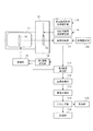
図1は、撮像装置の構成を示すブロックである。本実施形態において、撮像装置はカメラ本体とレンズが一体となったものを例に説明するが、これに限られるものではなく、撮像装置であるカメラ本体にレンズ装置が着脱可能に取り付けられているものでもよい。
第1実施形態における撮像装置は、レンズである撮像光学系11、カメラ本体12を含む。カメラ本体12は、CMOSやCCDなどの撮像素子を有する撮像部13、撮像部やレンズの駆動制御を行う駆動部、画像から座標を検出する検出部、画像処理を行う処理部、画像合成を行う画像合成部など有する。
(First embodiment)
FIG. 1 is a block diagram showing the configuration of the image pickup apparatus. In the present embodiment, the image pickup apparatus will be described by way of example in which the camera body and the lens are integrated. However, the present invention is not limited to this, and the lens apparatus is detachably attached to the camera body that is the image pickup apparatus. It may be one.
The image pickup apparatus according to the first embodiment includes an image pickup
撮像準備用撮像駆動部(準備用駆動部)14は、撮像に先立ち被写体を観察するために撮像部13を駆動し、静止画撮像用撮像駆動部(撮像用駆動部)15は、静止画撮像用に撮像部13を駆動する。ブレ補正部16は、カメラ本体に加わる像ブレを撮像光学系であるレンズ群の一部を移動させることで光学的に補正する。画像処理部17は、撮像部13の信号が入力され、その信号に対して輝度信号や色信号を形成するなどの信号処理を行ない、更にガンマ補正や圧縮処理を行う。第1座標検出部18は、撮像部13が時系列に出力する各画像の座標を求める。より具体的には、撮像部13が取得した画像の所定特徴点の座標を求め、次に取得する画像においても同一の特徴点の座標を求める。駆動部19は、第1座標検出部18の出力に基づいてブレ補正部16を駆動する。なお、ブレ補正部16でブレ補正された撮像光束が撮像部13に入射されるので、第1座標検出部18からの座標情報はブレ補正部16のブレ補正残りの座標情報となる。そして、撮像部13のブレ補正残りが少なくなるようにブレ補正部が駆動されるので、被写体観察中の像ブレによる観察画像劣化が軽減されることになる。
The imaging preparation imaging drive unit (preparation driving unit) 14 drives the
撮像操作部110は、撮像者が操作することで不図示であるピントや絞りの調整、シャッタの開閉制御を行い複数枚の静止画撮像を開始させる。撮像操作部110の信号は、静止画撮像用撮像駆動部15または撮像準備用撮像駆動部14に入力され、撮像操作部110の操作により撮像部13は静止画撮像およびその準備のための画像取得を行う。シャッタの開閉制御による露光時間は、像ブレによる画像劣化が目立たなくなる程度に短く設定される。また、像ブレによる画像劣化は撮像レンズの焦点距離が長いほど目立つため、上記露光時間も焦点距離に応じて変更される。
The image capturing
しかしながら、露光時間が短いと像ブレによる画像劣化は少ないが露出が不足する。そこで、連続して撮像した露出時間の短い複数の画像を順次合成して露出の不足を補う。そのため、撮像部13が取得する画像枚数は、各々の撮像画像の露光時間と生成する合成画像の適正な露出時間で決定される。例えば、撮像光学系11の焦点距離が長く各撮像の露光時間を短くする必要がある場合に、主被写体が暗いために合成画像の適正な露光時間が長くなるときには、撮像枚数は多くなる。
However, if the exposure time is short, the image deterioration due to the image blur is small, but the exposure is insufficient. Therefore, a plurality of consecutively captured images with short exposure times are sequentially combined to compensate for the lack of exposure. Therefore, the number of images acquired by the
連続して撮像した複数の画像を合成するときには、撮像間の像ブレにより各画像の構図は微妙に変化する。そして、構図が微妙に変化した画像を合成することにより画像劣化が生じてしまう。そのため本実施形態では、像ブレに起因する画像劣化を抑制するために、画像合成に先立って各画像の位置合わせを行う。
第2座標検出部111は、撮像部13が順次取得する複数の画像に対して、それぞれの構図の座標を検出する。より具体的には、主被写体の瞳等の様に各画像で共通する特徴点座標を画像ごとに求める。
When synthesizing a plurality of images captured continuously, the composition of each image slightly changes due to image blurring between the captured images. Then, the images are deteriorated by synthesizing the images whose composition is changed slightly. Therefore, in the present embodiment, in order to suppress the image deterioration due to the image blur, the positions of the images are aligned prior to the image combination.
The second
図2を参照して、第2座標検出部111、座標変換部112、画像合成部113について説明する。図2は、順次記憶される画像を示している。
第2座標検出部111は、まず、図2(A)の画像において主被写体左瞳21aを特徴点として設定する。そして、撮像部13で図2(A)の次に撮像された図2(B)の画像において、設定した特徴点(主被写体左瞳21b)の座標を求めている。図2(A)と図2(B)では、特徴点の座標が像ブレにより上下にAだけずれている。この特徴点の座標のずれ量は、一般的に動きベクトルと呼ばれている。
The second
The second
座標変換部112は、第2座標検出部111で求めた座標に基づいて画像をずらす。例えば、図2(A)の画像を基準として図2(B)の画像をAだけずらす、すなわち、図2(B)の画像を図2(A)の画像に対する特徴点の座標のずれ量に基づいてずらすことで構図のずれを補正する。
画像合成部113は、座標変換部112で座標変換された画像を合成する。
ここでは2枚の画像で説明したが、より多くの画像を合成する場合においても第2座標検出部111が各画像の特徴点の座標を検出し、座標変換部112が互いの画像間のズレを補正し、画像合成部113が座標変換された画像を合成して露出の適正化を図る。
The
The
Although two images are described here, the second coordinate
図3を参照して、トリミング部114について説明する。図3は、連続した撮像中の構図ズレとその補正を説明する図である。
トリミング部114は、画像を合成したことで生じた余分な領域をカットし、画像の大きさを整える。図3において、一点鎖線で示す枠31は図2(A)の画像、破線で示す枠32は図2(B)の画像であり、互いに位置をAだけズラして合成されている。実線のトリミング枠33は一点鎖線の枠31、破線の枠32と同じ大きさのトリミング枠であり2枚の画像における中心位置に設けられている。トリミング枠33をはみ出る画像は、トリミング部114においてカットされる。尚、トリミング枠33は2枚の画像の中心に限られるものではなく、合成を開始する一番初めの枠と同じ位置に設けるなどしてもよい。
表示部115は、トリミング部114でトリミングされた画像をカメラ本体12の背面液晶に表示する。また、記録部116は、トリミングされた画像を記録する。
The
The
The
図4は、本実施形態におけるブレ補正部の効果を説明する図である。
まず、ブレ補正部16を駆動しない場合を考える。図4(A)から図4(D)は、ブレ補正部16を駆動しない場合に撮像部13が連続して取得する画像であり、各々の画像は像ブレにより構図が微妙にずれている。
FIG. 4 is a diagram for explaining the effect of the blur correction unit in this embodiment.
First, consider a case where the
図4(F)の黒丸41から黒丸44は、図4(A)から図4(D)の画像における実線45で示した像ブレに起因した構図ズレを座標情報にした結果である。座標情報の取得タイミングは、座標算出演算時間を極めて短いとした場合には、画像信号をすべて取得した直後に得られることになる。すなわち、画像取得開始時の座標は、画像取得終了後である1フレーム分遅れて得られることになる。座標の変化を、破線46で示す。
図4(G)から図4(J)は、ブレ補正部16を駆動させた場合に、撮像部13が連続して取得する画像である。ブレ補正部16は、黒丸42及び黒丸43の座標情報に基づいて、座標が基準の破線49に近づくように、矢印47、48に示されるように駆動される。ブレ補正部16を駆動させることにより、図4(A)から図4(D)の画像は、図4(G)から図4(J)の画像となり、構図のずれを軽減できる。
FIGS. 4G to 4J are images that the
図4(G)から図4(J)では、ブレ補正が行われているのにもかかわらず、画像に僅かな構図ズレが発生している。これは、座標の検出が、画像の取得から1フレーム程度遅れることが影響している。そのため、画像取得の初期である図4(G)の画像に対して、図4(H)の画像は構図がずれることになる。また、黒丸43から黒丸44の様に構図のずれが生じない場合においてもその変化をすぐにブレ補正には反映できない。これにより、図4(J)は、図4(I)と構図がずれることになる。僅かな構図のズレが発生するため、ブレ補正後の各画像を合成する段階においても各画像の特徴点合わせ(座標変換)を行う。
4(G) to 4(J), a slight composition shift occurs in the image despite the shake correction being performed. This is because the detection of coordinates is delayed by about one frame from the acquisition of the image. Therefore, the composition of the image of FIG. 4(H) is displaced from that of the image of FIG. 4(G) which is the initial stage of image acquisition. Further, even when there is no composition shift from
なお、上記ではブレ補正部16を、画像取得の合間に(例えば、図4(C)から図4(D)の間など)に破線49に近づく矢印の量だけ駆動する場合を説明したが、これに限られるものではない。例えば、破線矢印410、411の様な駆動目標値を与えて、画像を露光している間にその画像の前後の座標情報の差分だけブレ補正部16が直線的に動く様に駆動してもよい。
また、上記は説明のためにブレ補正を行わない場合に検出した座標を基準にしているが、実際にはブレ補正を行いながら座標を求めるために得られる座標は構図ズレ補正残りとなる。そのため実際に求められる座標は図4(F)の黒丸41から黒丸44と多少異なってくる。
In the above description, the case where the
Further, the above description is based on the coordinates detected when the shake correction is not performed for the sake of description, but in reality, the coordinates obtained for obtaining the coordinates while performing the shake correction are the composition shift correction remaining. Therefore, the actually obtained coordinates are slightly different from the
図4(E)は、ブレ補正部16を駆動させない場合である図4(A)から図4(D)の画像合成結果である。主被写体の位置を合わせて画像を合成した結果、破線412や一点鎖線413、二点鎖線414で示すように各画像の撮像領域が異なってくる。そのため、実線415でトリミングしたときに、その領域内で画像合成枚数が足りずに露出が不足する範囲が多く存在する。すなわち高品位の画像を得ることが出来ない。
FIG. 4(E) shows the image composition result of FIG. 4(A) to FIG. 4(D) when the
図4(K)は、ブレ補正部16を駆動させた場合である図4(G)から図4(J)の画像合成結果である。主被写体の位置を合わせて画像を合成した結果、破線416や一点鎖線417で示すように異なる撮像領域が生まれる。これは上述した座標信号の遅れに起因する、画像のずれによるものである。しかしながら、各画像の撮像領域ズレが少なく、実線でトリミングしたときの画像合成枚数も適正な露出を確保するのに十分なものであり、図4(E)の画像より高品位な画像が得られる。
FIG. 4K shows the image composition result of FIGS. 4G to 4J when the
図5は、第1実施形態の撮像動作の流れを説明するフローチャートである。説明を分かりやすくするために、撮像装置の動作フローにおいて本実施形態とは直接関係しないステップは省いている。図5のフローは、撮像装置の主電源オンによりスタートする。
ステップS5001では、撮像操作部110であるレリーズボタン半押し(S1)までこのステップを循環して待機し、レリーズボタン半押し(S1 on)でステップS5002に進む。レリーズ半押し(S1)は、撮像準備の操作である。
FIG. 5 is a flowchart illustrating the flow of the image capturing operation according to the first embodiment. For the sake of clarity, steps in the operation flow of the image pickup apparatus that are not directly related to this embodiment are omitted. The flow of FIG. 5 starts when the main power of the image pickup apparatus is turned on.
In step S5001, this step is cycled until the release button half-press (S1), which is the image capturing
ステップS5002では、撮像部13は、準備用駆動部15の入力に従って画像を取得する(画像取得1)。この画像取得は、撮像に先立って予め撮像構図を定めるための画像取得である。そのため、後述するステップS5009の画像取得より、撮像信号の間引きなどにより、撮像サイズが小さくてもよい。
ステップS5003では、第1座標検出部18が、ステップS5002で取得した画像の所望の特徴点の座標を検出する(座標検出1)。
ステップS5004では、S5003で検出した座標に基づいて、駆動部19がブレ補正部16を駆動し、光学的に像ブレを補正する。
ステップS5005では、ステップS5002で取得した画像を表示部115に表示する(表示1)。これにより、表示部115には撮像に先だって像ブレによる劣化の少ない画像が表示され、被写体観察中の像ブレによる観察画像劣化を軽減できる。
In step S5002, the
In step S5003, the first coordinate
In step S5004, the
In step S5005, the image acquired in step S5002 is displayed on the display unit 115 (display 1). As a result, an image with little deterioration due to image blur is displayed on the
ステップS5006では、撮像操作部110であるレリーズボタンの押し切り(S2 on)で、撮像(露光開始)の指示が行われるまでステップS5001からステップS5006を循環する。
ステップS5007では、露光開始の指示が行われると、撮影用駆動部14が、撮像光学系11の焦点距離に応じて像ブレの許容できる露光時間を設定する。例えば焦点距離をfとすると露光時間を1/fに設定する。また、撮影用駆動部14が、撮像被写体の明るさと設定された露光時間に応じて連続撮像の撮像枚数を設定する。例えば、撮像被写体に適正な露光時間に対して設定した露光時間が1/4の長さの場合には、4枚撮像を設定する。なお、合成により適正な露光時間で撮像したときと同等の明るさの画像を取得できればよいので、例えば、撮像被写体に適正な露光時間に対して設定した露光時間が1/4の長さの場合に5枚以上の撮像を行ってもよい。
In step S5006, steps S5001 to S5006 are cycled until the image capturing (exposure start) instruction is issued by pressing the release button (S2 on) which is the image capturing
In step S5007, when an instruction to start exposure is issued, the photographing
ステップS5008では、撮像部13が、撮像用駆動部14からの指示に基づいて、画像を取得する(画像取得2)。
ステップS5009では、第1座標検出部18が、ステップS5008で取得した画像の座標を検出する(座標検出2)。
ステップS5010では、駆動部19が、ステップS5009で検出した座標に基づいてブレ補正部16を駆動し、光学的に像ブレを補正する。ここでは、ステップS5008で取得した画像の特徴点の座標と、ステップS5008よりも前に取得した画像の特徴点の座標とのずれ量に基づいて光学的に像ブレを補正すればよい。
ステップS5011では、ステップS5007で設定した撮像枚数に達するまでステップS5008からステップS5011を循環して連続した撮像を進める。そして設定枚数の撮像が終了すると、ステップS5012に進む。
In step S5008, the
In step S5009, the first coordinate
In step S5010, the
In step S5011, steps S5008 to S5011 are cycled to continue continuous imaging until the number of images set in step S5007 is reached. When the set number of images have been captured, the process proceeds to step S5012.
ステップS5012では、第2座標検出部111が、ステップS5010で取得した各画像の特徴点座標を検出する(座標検出3)。
ステップS5013では、座標変換部112が、ブレ補正部16の補正残りを座標変換して補正する。
ステップS5014では、画像合成部113が、ステップS5013で座標変換して構図を揃えた画像を合成する。これにより、例えば図4(K)に示されるような、合成画像が得られる。ここで、露光時間の合計が適正な露光時間よりも長くなるように余分に画像を取得している場合には、補正残りが最も多い画像は合成対象から除外するようにしてもよい。
ステップS5015では、トリミング部114が、合成した画像をトリミングして適正な画像サイズにトリミングし、記録画像を生成する。
In step S5012, the second coordinate
In step S5013, the coordinate
In step S5014, the
In step S5015, the
ステップS5016では、ステップS5015で記録画像を記録部116に記録する。
ステップS5017では、表示部115に記録画像を表示する(表示2)。
ステップS5018ではレリーズボタンの半押し(S1 on)が継続されているか否かを判断する。半押しが継続されている間はステップS5002に戻り以上説明したフローを繰り返し、レリーズボタンの半押しが解除された時にはこのフローは終了する。
In step S5016, the recording image is recorded in the
In step S5017, the recorded image is displayed on the display unit 115 (display 2).
In step S5018, it is determined whether the release button has been half pressed (S1 on). While half-pushing is continued, the process returns to step S5002 and the above-described flow is repeated. When half-pushing of the release button is released, this flow ends.
以上説明したように、複数枚の画像を取得している間の像ブレによる構図変化を、画像取得中の座標信号に基づいてブレ補正部を駆動することで軽減し、さらに、位置合わせを行い合成することで、露出不足の領域が少ない高品位な画像を得ることができる。 As described above, composition change due to image blur during the acquisition of a plurality of images is reduced by driving the blur correction unit based on the coordinate signal during image acquisition, and further alignment is performed. By synthesizing, it is possible to obtain a high-quality image with few underexposed areas.
(第2実施形態)
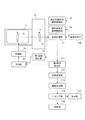
図6は、第2実施形態が適用される撮像装置の構成を示したブロック図である。図6と図1との違いは、予測部61が設けられている点である。予測部61は、現在の信号とその前の信号から、次の信号を予測する。予測部61は、例えばカルマンフィルタなどの公知の技術で構成されている。予測部61は、第1座標検出部18や第2座標検出部111から取得した座標信号に基づいて次の座標信号の予測を行い、予測結果を駆動部19に出力する。駆動部19は、予測結果に基づきブレ補正部16を駆動する。
(Second embodiment)
FIG. 6 is a block diagram showing the configuration of an image pickup apparatus to which the second embodiment is applied. The difference between FIG. 6 and FIG. 1 is that the
第1実施形態において説明したように、連続する画像の構図ズレを表す座標信号は画像信号が取得された後に求められるために、座標信号は画像信号取得時より1フレーム程度遅くなる。予測部61は、今得られた座標信号とその前に得られた座標信号に基づいて、次の座標信号を予測する。そのため、画像が取得される時点におけるその画像の構図ズレを示す信号を得ることができる。
As described in the first embodiment, since the coordinate signal representing the composition deviation of continuous images is obtained after the image signal is acquired, the coordinate signal is delayed by about one frame from the time when the image signal is acquired. The
図7は、第2実施形態におけるブレ補正部の効果を説明する図である。
図7(A)の黒丸41〜黒丸44は、図4(F)と同じ座標情報を示している。それに対して、白丸71〜白丸74は、黒丸41〜黒丸44を予測部61で処理した結果である。白丸71〜白丸74は、画像取得開始時にその画像の構図ズレを座標情報として遅れなく検出した結果と等しくなるため、実線45の像ブレと重なっている。
FIG. 7 is a diagram for explaining the effect of the blur correction unit in the second embodiment.
ブレ補正部16は、白丸72から白丸74の座標情報に基づいて、座標が基準の破線49に近づくように、矢印75から矢印77に示されるように駆動される。ブレ補正部16を駆動させることにより、図4(A)から図4(D)の画像は図7(B)から図7(E)の画像となり、構図のずれを軽減できる。
なお、ブレ補正部16の駆動は、矢印75から矢印77に示されるような駆動に限られるものではない。例えば、或いは破線矢印78から破線矢印710のような駆動目標値を与え、画像を露光している間にその画像の前後の座標情報の差分だけブレ補正部16が直線的に動くように駆動してもよい。
また、図4を用いて説明したときと同様に、図7においても説明のためにブレ補正を行わない場合に検出した座標を基準にしているが、実際にはブレ補正を行いながら座標を求めるために得られる座標は構図ズレ補正残りとなる。そのため、実際に求められる座標である白丸71から白丸74は図7(A)とは多少異なってくる。
The
The drive of the
Further, as in the case described with reference to FIG. 4, in FIG. 7 the coordinates detected when the shake correction is not performed are used as a reference for the purpose of explanation, but the coordinates are actually obtained while performing the shake correction. The coordinates thus obtained are the composition shift correction remaining. Therefore, the
図7(F)は、ブレ補正部16を駆動させた場合である図7(B)から図7(E)の画像を、主被写体の位置を合わせて合成した結果である。図7(F)は、図7(B)から図7(E)の各画像の撮像領域ズレが少ないため、予測部61を有しない撮像装置で得られた図4(K)の画像より高品位な画像が得られる。
FIG. 7(F) shows the result of combining the images of FIGS. 7(B) to 7(E) when the
図8は、第2実施形態における撮像動作の流れを説明するフローチャートである。図8において第1実施形態のフローチャート(図5)と同じステップには同じ符号を付し、その説明は省略する。
ステップS8001では、予測部61が、第1座標検出部18から順次送られてくるS5003で検出された座標信号に基づいて1フレーム先の座標信号を予測する。予測された座標信号(予測信号)は、駆動部19に送られる。
ステップS5004では、駆動部19が、予測信号に基づいてブレ補正部16を駆動する。これにより、被写体観察中の像ブレによる観察画像劣化を高い精度で軽減できる。
FIG. 8 is a flowchart illustrating the flow of the image pickup operation in the second embodiment. In FIG. 8, the same steps as those in the flowchart (FIG. 5) of the first embodiment are designated by the same reference numerals and the description thereof will be omitted.
In step S8001, the
In step S5004, the
同様に、ステップS8002では、予測部61が、第1座標検出部18から順次送られてくるS5008で検出された座標信号に基づいて、1フレーム先の座標信号を予測する。予測された座標信号(予測信号)は、駆動部19に送られる。
ステップS5010では、駆動部19が、この予測信号に基づいてブレ補正部16を駆動する。この動作により複数枚の撮像画像には、ほぼ構図ズレがなくなる。
Similarly, in step S8002, the
In step S5010, the
しかしながらブレ補正部16のメカニカルな摩擦や制御不足によるブレ補正誤差も含まれる。そこで、ステップS5012、ステップS5013で再度撮像された画像の座標を求め座標変換を行うことでこの誤差を更に小さくしている。
以上説明したように、第2実施形態においては予測部61を設けることで画像取得時の構図ズレを予測して検出できるようになり、合成画像の品位を更に向上させることができる。
However, a blur correction error due to mechanical friction of the
As described above, in the second embodiment, by providing the
撮像部13がCMOSイメージセンサの場合には、特徴点の読み出しタイミングが画面上の特徴点位置により変わる。この特性を利用することにより、画像の構図ずれを早期に求め、予測部61の作動を制御することも可能になる。
図9(A)から図9(D)はCMOSイメージセンサを用いた撮像部が時系列に取得した画像である。
この画像において画像を領域91、領域92、領域93で分ける。CMOSイメージセンサ形式の撮像部では時系列的に画像を取得できるため、各々の領域における画像信号取得のタイミングを図9(A)のA、B、Cのように異ならせることができる。
When the
9A to 9D are images acquired in time series by the imaging unit using the CMOS image sensor.
In this image, the image is divided into a
例えば、所定の領域である領域91に特徴点がある場合にはタイミングAで取得した画像から、図9(E)の黒丸94から黒丸97の座標情報を得ることができる。タイミングAは次の画像取得開始のタイミングに対して大きな遅れは無いために、特徴点が読み出しの早い所定の領域にある場合にはその情報でブレ補正を行えばよい。
また、領域92に特徴点がある場合にはタイミングBで取得した画像から、図9(F)の黒丸98から黒丸911の座標情報を得ることができる。領域93に特徴点がある場合には、図4と同じようにタイミングCで取得した画像から座標情報を得る。タイミングBで画像を取得した場合にはタイミングCで取得した場合よりも実測から予測迄の時間が短いため予測部61による予測精度を上げることができる。
このように画像の中の特徴点が存在する領域に基づいて予測部61を制御することで、予測負荷の軽減や予測精度の向上も可能になる。
For example, when there is a characteristic point in the
Further, when there are characteristic points in the
By controlling the
図10は、撮像部13がCMOSの場合における撮像動作のフローを説明するフローチャートであり、図8のフローチャートと同じステップは同じ符号を付し、説明は省く。
ステップS10001では、予測部61が、ステップS5003で座標検出を行った第1座標検出部から順次送られてくる座標信号の特徴点が、図9(A)の領域91に存在するか否か判断する。領域91に存在する場合には、予測を行うステップであるステップS8001をスキップし、ステップS5004に進む。
FIG. 10 is a flow chart for explaining the flow of the image pickup operation when the
In step S10001, the
またステップS10002でも、同様に予測部61が、ステップS5009で座標検出を行った第1座標検出部から順次送られてくる座標信号の特徴点が、図9(A)の領域91に存在するか否か判定する。特徴点が図9(A)の領域91に存在する場合には、次のステップであるステップS8002をスキップし、ステップS5010に進む。
このように、撮像部13がCMOSイメージセンサの場合には、特徴点が画像内の何処に配置されているかに基づいて予測部61の作動を制御することができるため、予測負荷を軽減することができる。
Also in step S10002, similarly, whether the predicting
As described above, when the
(第3実施形態)
図11は、第3実施形態が適用される撮像装置の構成を示すブロック図である。図11と図6との違いは、コマ間座標検出用撮像駆動部(コマ間座標部)1101が設けられている点である。コマ間座標部1101は、合成画像を作るために静止画を複数取得する間に、構図ズレの座標検出を目的としたコマ間画像を取得するよう撮像部13を駆動する。
(Third Embodiment)
FIG. 11 is a block diagram showing the arrangement of an image pickup apparatus to which the third embodiment is applied. The difference between FIG. 11 and FIG. 6 is that an inter-frame coordinate detection image pickup drive section (inter-frame coordinate section) 1101 is provided. The inter-frame coordinate
第1実施形態及び第2実施形態においては、静止画用に取得した画像から第1座標検出部が構図ズレの座標情報を取得し、それに基づいて駆動部19がブレ補正部16を駆動していた。第3実施形態では、静止画露光の合間に座標情報を得ることを目的としたコマ間画像の取得を行う。このコマ間画像は、サイズの小さな画像でもよく、また、露光時間も静止画露光にあわせる必要はない。静止画撮像の連写間に挿入される画像取得であるために、特徴点の座標情報が得られる範囲でできるだけ連写間隔を妨げない短い露光時間が好ましい。
In the first embodiment and the second embodiment, the first coordinate detection unit acquires the coordinate information of the composition shift from the image acquired for the still image, and the
コマ間座標部1101の動作を、図12を参照して説明する。図12は、第3実施形態における撮像中の構図ズレ補正を説明する図である。
図12(A)において、画像1201〜画像1203は、撮像準備中の被写体観察を目的とした画像であり、準備用駆動部15の指示に従って撮像部13が画像を取得する。これら画像の露光時間T1は、例えば1/30秒や1/60秒のように動画撮像等に適した露光時間等に設定される。
The operation of the inter-frame coordinate
In FIG. 12A,
画像1205、画像1207、画像1209、画像1211は、静止画を得ることを目的とした画像であり、撮像用駆動部14の指示に従って撮像部13は画像を取得する。これら画像の露光時間T2は、例えば1/60秒など、撮像光学系の焦点距離や被写体距離に基づいて像ブレによる画質劣化の影響が少ない時間に設定される。
画像1204、画像1206、画像1208、画像1210は、静止画撮像の合間に座標情報を得ることを目的としたコマ間画像であり、コマ間座標部1101の指示に従って撮像部13は画像を取得する。これらコマ間画像の露光時間T3は、例えば1/120秒など、コマ間画像から座標情報が求められる明るさとなる最短時間に設定される。
The
An
いま、準備用の画像、静止画撮像用の画像及びコマ間画像において特徴点が矢印1212〜1218のタイミングで画像情報を取得し座標情報が算出されるとする。
図12(B)において実線1219は、画像取得中の像ブレによる画像の構図ズレ変化を示す。黒丸1220から黒丸1222は画像1201から画像1203の各々の画像取得後に得られる座標情報を示し、黒丸1223から黒丸1226は画像1204、画像1206、画像1208、画像1210の画像取得後に得られる座標情報を示す。破線1227は、これら座標情報から求めた構図ズレである。
Now, suppose that in the preparation image, the still image capturing image, and the inter-frame image, the characteristic points acquire image information at the timing of
In FIG. 12B, a
白丸1228〜白丸1234は、それまでの座標情報(黒丸1220から黒丸1226など)に基づいて予測部61が予測する予測座標情報であり、時系列的に得られる各々の画像取得領域における重心タイミングAからGにおける座標予測結果である。白丸1228〜白丸1234で求まる軌跡(実線1219で示した像ブレによる画像の構図ズレ変化と同じになる)に基づいて駆動部19がブレ補正部16を駆動することで、画像間の構図ズレを良好に補正しつつ撮像を続行できる。
また、静止画用画像の各画像からも座標情報を求め、それぞれの画像取得タイミングにおける座標情報からも、予測部61による予測により予測座標情報を得ることができる。予測座標情報も用いてブレ補正を行うことで、より滑らかで高精度なブレ補正が行われる。
Further, the coordinate information can be obtained from each image of the still image, and the predicted coordinate information can be obtained by the prediction by the
以上説明したように、静止画用の画像取得の合間に、撮像準備のための画像取得と同じサイズの画像で座標情報を得ることができるため、撮像準備から静止画撮像中の一連の動作において安定した座標情報を得ることができる。そのため、第3実施形態においては静止画撮像の合間に座標情報取得用の画像を挿入することで安定したブレ補正が行え、合成画像の品位を更に向上させることができる。座標情報取得タイミングを画像の領域ごとに細分化することで、滑らかなブレ補正も可能になる。 As described above, since the coordinate information can be obtained with the image of the same size as the image acquisition for the image acquisition preparation during the image acquisition for the still image, the series of operations from the imaging preparation to the still image imaging It is possible to obtain stable coordinate information. Therefore, in the third embodiment, stable blur correction can be performed by inserting an image for coordinate information acquisition between still image pickups, and the quality of the composite image can be further improved. By subdividing the coordinate information acquisition timing for each image area, smooth blur correction is also possible.
(第4実施形態)
第1実施形態から第3実施形態において、第1座標検出部18及び第2座標検出部111における各画像の座標の検出は、1つの特徴点の座標を求めることで行われていたが、これに限られるものではない。例えば、各画像において複数の特徴点を設定し、それぞれの特徴点の座標を検出するようにしてもよい。例えば、動く被写体を撮影する場合には、主被写体に設定された特徴点のみを用いて座標を検出する。一方、静止している被写体を撮影する場合には、撮像領域全体に設定された特徴点と主被写体に設定された特徴点を用いて座標を検出する。撮像装置に、撮影対象が動く被写体であるのか静止している被写体であるのかの判定を行い、判定結果に基づいて撮影モード(検出方法)を切り替える切替手段を備えるようにしてもよい。切替手段は、例えば、顔検出や動物検知の機能により、主被写体が動体であるか否か判定する。被写体に応じて座標情報の取得方法を切り替えることで、より高精度な補正を行うことができ、画像の品位を向上させることができる。
なお、上記の4つの実施形態では、撮像装置が画像合成及びトリミングを行う例を説明したが、撮像装置は画像合成に用いる画像を取得するための撮像時に光学的にブレ補正を行う構成であればよく、取得した画像を外部に送信し外部機器で画像合成してもよい。
また、上記の4つの実施形態では、光学的にブレ補正を行うためにレンズを移動させる例を説明したが、撮像部13の撮像素子を移動させてもよい。
(Fourth Embodiment)
In the first to third embodiments, the detection of the coordinates of each image by the first coordinate
It should be noted that in the above four embodiments, an example in which the image pickup apparatus performs image combination and trimming has been described, but the image pickup apparatus may be configured to optically perform blurring correction during image pickup to obtain an image used for image combination. The acquired image may be transmitted to the outside and the image may be combined by an external device.
Further, in the above four embodiments, the example in which the lens is moved to optically perform the shake correction has been described, but the image pickup device of the
(その他の実施例)
本発明は、上述の実施形態の1以上の機能を実現するプログラムを、ネットワーク又は記憶媒体を介してシステム又は装置に供給し、そのシステム又は装置のコンピュータにおける1つ以上のプロセッサーがプログラムを読出し実行する処理でも実現可能である。また、1以上の機能を実現する回路(例えば、ASIC)によっても実現可能である。
(Other embodiments)
The present invention supplies a program that implements one or more functions of the above-described embodiments to a system or apparatus via a network or a storage medium, and one or more processors in a computer of the system or apparatus read and execute the program. It can also be realized by the processing. It can also be realized by a circuit (for example, ASIC) that realizes one or more functions.
以上、本発明の好ましい実施形態について説明したが、本発明は、これらの実施形態に限定されず、その要旨の範囲内で種々の変形および変更が可能である。 Although the preferred embodiments of the present invention have been described above, the present invention is not limited to these embodiments, and various modifications and changes can be made within the scope of the gist thereof.
13 撮像部
18 座標検出変換1
19 駆動部
111 座標検出部2
112 座標変換部
113 画像合成部
13
19
112 coordinate
Claims (10)
撮像部と、
前記撮像部で撮像された複数の画像間の位置ずれを検出する検出部と、
前記検出部により検出された位置ずれに基づいて、光学的に画像の像ブレを補正する振れ補正部を駆動する駆動部と、
前記検出部により検出された位置ずれに基づいて、前記像ブレが補正された複数の画像の座標交換を行う座標変換部と、を有し、
前記検出部は、前記合成画像を生成する際に合成されない画像を含む複数の画像間の位置ずれを検出することを特徴とする撮像装置。 An imaging device for generating a composite image using a plurality of images captured consecutively,
An imaging unit,
A detection unit that detects a positional deviation between a plurality of images captured by the imaging unit;
A drive unit that drives a shake correction unit that optically corrects the image blur of the image based on the positional deviation detected by the detection unit;
A coordinate conversion unit that performs coordinate exchange of the plurality of images in which the image blur has been corrected based on the positional deviation detected by the detection unit ,
The image pickup apparatus , wherein the detection unit detects a positional shift between a plurality of images including images that are not combined when the combined image is generated .
前記駆動部は、前記予測部により予測された位置ずれに基づいて、振れ補正部を駆動することを特徴とする請求項1に記載の撮像装置。 Based on the positional deviation detected by the detection unit, a prediction unit for predicting the positional deviation of the image acquired next,
The image pickup apparatus according to claim 1, wherein the drive unit drives the shake correction unit based on the positional deviation predicted by the prediction unit.
前記駆動部は、前記検出部が検出した前記特徴点が、所定の領域にある場合には、前記検出部により検出された位置ずれに基づいて振れ補正部を駆動し、前記特徴点が前記所定の領域にない場合には、前記予測部により予測された位置ずれに基づいて、振れ補正部を駆動することを特徴とする請求項3または4に記載の撮像装置。 The imaging unit is a CMOS image sensor,
When the feature point detected by the detection unit is in a predetermined area, the drive unit drives the shake correction unit based on the positional deviation detected by the detection unit, and the feature point is the predetermined value. The image pickup apparatus according to claim 3, wherein the shake correction unit is driven based on the positional deviation predicted by the prediction unit when the image is not in the area.
撮像工程と、
撮像された複数の画像間の位置ずれを検出する検出工程と、
前記検出工程において検出された位置ずれに基づいて、光学的に画像の像ブレを補正する振れ補正部を駆動する駆動工程と、
前記検出工程において検出された位置ずれに基づいて、前記像ブレが補正された複数の画像の座標変換を行う座標変換工程と、を有し、
前記検出工程では、前記合成画像を生成する際に合成されない画像を含む複数の画像間の位置ずれを検出することを特徴とする制御方法。 A method for controlling an imaging device, which generates a composite image using a plurality of images captured consecutively,
Imaging process,
A detection step of detecting a positional deviation between the plurality of captured images,
A drive step of driving a shake correction section that optically corrects an image blur of an image based on the positional deviation detected in the detection step;
The detection based on the detected positional deviation in the process, has a coordinate conversion step of performing coordinate transformation of a plurality of images in which the image blur has been corrected,
In the detecting step, when the composite image is generated, a positional shift between a plurality of images including images that are not combined is detected .
Priority Applications (2)
| Application Number | Priority Date | Filing Date | Title |
|---|---|---|---|
| JP2016151637A JP6740052B2 (en) | 2016-08-02 | 2016-08-02 | Imaging device and control method thereof |
| US15/658,678 US10257437B2 (en) | 2016-08-02 | 2017-07-25 | Imaging apparatus and control method for positioning a plurality of images continuously captured by an image sensor |
Applications Claiming Priority (1)
| Application Number | Priority Date | Filing Date | Title |
|---|---|---|---|
| JP2016151637A JP6740052B2 (en) | 2016-08-02 | 2016-08-02 | Imaging device and control method thereof |
Publications (3)
| Publication Number | Publication Date |
|---|---|
| JP2018022964A JP2018022964A (en) | 2018-02-08 |
| JP2018022964A5 JP2018022964A5 (en) | 2019-09-05 |
| JP6740052B2 true JP6740052B2 (en) | 2020-08-12 |
Family
ID=61069899
Family Applications (1)
| Application Number | Title | Priority Date | Filing Date |
|---|---|---|---|
| JP2016151637A Active JP6740052B2 (en) | 2016-08-02 | 2016-08-02 | Imaging device and control method thereof |
Country Status (2)
| Country | Link |
|---|---|
| US (1) | US10257437B2 (en) |
| JP (1) | JP6740052B2 (en) |
Families Citing this family (7)
| Publication number | Priority date | Publication date | Assignee | Title |
|---|---|---|---|---|
| JP6894725B2 (en) * | 2017-03-09 | 2021-06-30 | キヤノン株式会社 | Image processing device and its control method, program, storage medium |
| US10594940B1 (en) * | 2018-01-12 | 2020-03-17 | Vulcan Inc. | Reduction of temporal and spatial jitter in high-precision motion quantification systems |
| CN110493488B (en) * | 2018-05-15 | 2021-11-26 | 株式会社理光 | Video image stabilization method, video image stabilization device and computer readable storage medium |
| US11044404B1 (en) | 2018-11-28 | 2021-06-22 | Vulcan Inc. | High-precision detection of homogeneous object activity in a sequence of images |
| US10872400B1 (en) | 2018-11-28 | 2020-12-22 | Vulcan Inc. | Spectral selection and transformation of image frames |
| KR20200081527A (en) | 2018-12-19 | 2020-07-08 | 삼성전자주식회사 | Electronic apparatus and control method thereof |
| JP2022187800A (en) * | 2021-06-08 | 2022-12-20 | キヤノン株式会社 | Imaging apparatus and method for controlling the same, as well as program |
Family Cites Families (8)
| Publication number | Priority date | Publication date | Assignee | Title |
|---|---|---|---|---|
| JPH09261526A (en) | 1996-03-19 | 1997-10-03 | Olympus Optical Co Ltd | Image pickup device |
| JP4708819B2 (en) * | 2005-03-14 | 2011-06-22 | キヤノン株式会社 | Image processing apparatus, method, computer program, and storage medium |
| WO2007032082A1 (en) * | 2005-09-16 | 2007-03-22 | Fujitsu Limited | Image processing method, and image processing device |
| JP5204785B2 (en) * | 2007-12-03 | 2013-06-05 | パナソニック株式会社 | Image processing apparatus, photographing apparatus, reproduction apparatus, integrated circuit, and image processing method |
| JP2012191486A (en) * | 2011-03-11 | 2012-10-04 | Sony Corp | Image composing apparatus, image composing method, and program |
| KR102179731B1 (en) * | 2013-03-29 | 2020-11-17 | 소니 주식회사 | Image-capturing device, solid-state image-capturing element, camera module, electronic device, and image-capturing method |
| US9369630B2 (en) * | 2013-07-31 | 2016-06-14 | Samsung Electronics Co., Ltd. | Electronic apparatus and method of controlling the same |
| JP6170395B2 (en) * | 2013-09-26 | 2017-07-26 | キヤノン株式会社 | Imaging apparatus and control method thereof |
-
2016
- 2016-08-02 JP JP2016151637A patent/JP6740052B2/en active Active
-
2017
- 2017-07-25 US US15/658,678 patent/US10257437B2/en active Active
Also Published As
| Publication number | Publication date |
|---|---|
| US20180041716A1 (en) | 2018-02-08 |
| US10257437B2 (en) | 2019-04-09 |
| JP2018022964A (en) | 2018-02-08 |
Similar Documents
| Publication | Publication Date | Title |
|---|---|---|
| JP6740052B2 (en) | Imaging device and control method thereof | |
| JP4378272B2 (en) | Imaging device | |
| US9253398B2 (en) | Imaging apparatus for generating composite image using directional indicator image, and method and recording medium with program recorded therein for the same | |
| JP6825073B2 (en) | Imaging equipment, control methods, and programs | |
| US20070019104A1 (en) | Image pick-up apparatus, image pick-up program, and image processing program | |
| EP3383023B1 (en) | Imaging apparatus, control method, and non-transitory storage medium | |
| JP6104060B2 (en) | Imaging apparatus and imaging method | |
| KR100871639B1 (en) | Camera and image processing method for camera | |
| JP2014211574A (en) | Imaging apparatus, and control method and program therefor | |
| US10116856B2 (en) | Imaging apparatus and imaging method for controlling a display while continuously adjusting focus of a focus lens | |
| JPWO2013146506A1 (en) | Imaging apparatus and imaging method | |
| JP2018031877A (en) | Image pickup device and focus adjusting method | |
| JP2019033308A (en) | Image processing system, image processing method, image processing program and imaging apparatus | |
| US11283988B2 (en) | Imaging apparatus | |
| JP2013205781A (en) | Imaging apparatus | |
| JP2013141105A (en) | Image processing device, electronic camera, and image processing program | |
| US11044397B2 (en) | Image capturing device and image processing device, control methods of the same, and storage medium | |
| US12022208B2 (en) | Imaging apparatus with multiple frame recording and control shooting period | |
| US11736658B2 (en) | Image pickup apparatus, image pickup method, and storage medium | |
| JP2009033612A (en) | Imaging apparatus | |
| JP7532040B2 (en) | Imaging device and control method thereof | |
| US11924549B2 (en) | Imaging apparatus | |
| JP6739357B2 (en) | Imaging device and focus adjustment method | |
| JP2007049408A (en) | Photographing device | |
| JP4533175B2 (en) | Imaging device |
Legal Events
| Date | Code | Title | Description |
|---|---|---|---|
| A521 | Request for written amendment filed |
Free format text: JAPANESE INTERMEDIATE CODE: A523 Effective date: 20190726 |
|
| A621 | Written request for application examination |
Free format text: JAPANESE INTERMEDIATE CODE: A621 Effective date: 20190726 |
|
| A977 | Report on retrieval |
Free format text: JAPANESE INTERMEDIATE CODE: A971007 Effective date: 20200226 |
|
| A131 | Notification of reasons for refusal |
Free format text: JAPANESE INTERMEDIATE CODE: A131 Effective date: 20200303 |
|
| A601 | Written request for extension of time |
Free format text: JAPANESE INTERMEDIATE CODE: A601 Effective date: 20200501 |
|
| A521 | Request for written amendment filed |
Free format text: JAPANESE INTERMEDIATE CODE: A523 Effective date: 20200611 |
|
| TRDD | Decision of grant or rejection written | ||
| A01 | Written decision to grant a patent or to grant a registration (utility model) |
Free format text: JAPANESE INTERMEDIATE CODE: A01 Effective date: 20200623 |
|
| A61 | First payment of annual fees (during grant procedure) |
Free format text: JAPANESE INTERMEDIATE CODE: A61 Effective date: 20200722 |
|
| R151 | Written notification of patent or utility model registration |
Ref document number: 6740052 Country of ref document: JP Free format text: JAPANESE INTERMEDIATE CODE: R151 |