JP6739320B2 - Storage device separator - Google Patents
Storage device separator Download PDFInfo
- Publication number
- JP6739320B2 JP6739320B2 JP2016225887A JP2016225887A JP6739320B2 JP 6739320 B2 JP6739320 B2 JP 6739320B2 JP 2016225887 A JP2016225887 A JP 2016225887A JP 2016225887 A JP2016225887 A JP 2016225887A JP 6739320 B2 JP6739320 B2 JP 6739320B2
- Authority
- JP
- Japan
- Prior art keywords
- separator
- polymer
- storage device
- thermoplastic
- mass
- Prior art date
- Legal status (The legal status is an assumption and is not a legal conclusion. Google has not performed a legal analysis and makes no representation as to the accuracy of the status listed.)
- Active
Links
Classifications
-
- Y—GENERAL TAGGING OF NEW TECHNOLOGICAL DEVELOPMENTS; GENERAL TAGGING OF CROSS-SECTIONAL TECHNOLOGIES SPANNING OVER SEVERAL SECTIONS OF THE IPC; TECHNICAL SUBJECTS COVERED BY FORMER USPC CROSS-REFERENCE ART COLLECTIONS [XRACs] AND DIGESTS
- Y02—TECHNOLOGIES OR APPLICATIONS FOR MITIGATION OR ADAPTATION AGAINST CLIMATE CHANGE
- Y02E—REDUCTION OF GREENHOUSE GAS [GHG] EMISSIONS, RELATED TO ENERGY GENERATION, TRANSMISSION OR DISTRIBUTION
- Y02E60/00—Enabling technologies; Technologies with a potential or indirect contribution to GHG emissions mitigation
- Y02E60/10—Energy storage using batteries
-
- Y—GENERAL TAGGING OF NEW TECHNOLOGICAL DEVELOPMENTS; GENERAL TAGGING OF CROSS-SECTIONAL TECHNOLOGIES SPANNING OVER SEVERAL SECTIONS OF THE IPC; TECHNICAL SUBJECTS COVERED BY FORMER USPC CROSS-REFERENCE ART COLLECTIONS [XRACs] AND DIGESTS
- Y02—TECHNOLOGIES OR APPLICATIONS FOR MITIGATION OR ADAPTATION AGAINST CLIMATE CHANGE
- Y02P—CLIMATE CHANGE MITIGATION TECHNOLOGIES IN THE PRODUCTION OR PROCESSING OF GOODS
- Y02P70/00—Climate change mitigation technologies in the production process for final industrial or consumer products
- Y02P70/50—Manufacturing or production processes characterised by the final manufactured product
Description
本発明は、蓄電デバイス用セパレータに関する。 The present invention relates to a power storage device separator.
近年、非水電解液電池等の蓄電デバイスの開発が、活発に行われている。通常、非水電解液電池には、微多孔膜を含むセパレータが正負極間に設けられている。セパレータは、正負極間の直接的な接触を防ぎ、かつ微多孔中に保持した電解液を通じてイオンを透過させる機能を有する。 In recent years, development of electricity storage devices such as non-aqueous electrolyte batteries has been actively conducted. Usually, in a non-aqueous electrolyte battery, a separator including a microporous membrane is provided between the positive and negative electrodes. The separator has a function of preventing direct contact between the positive and negative electrodes and a function of allowing ions to permeate through the electrolytic solution held in the micropores.
ポリオレフィン微多孔膜は、電子絶縁体であるが、多孔構造によりイオン透過性を示すことから、非水電解液電池用セパレータとして広く利用されている。ポリオレフィン微多孔膜は、非水電解液電池が異常発熱を起こした際に、熱溶融により多孔を閉塞させて、電解液中のイオン伝導を遮断し、電気化学反応の進行を停止させるシャットダウン機能も有する。 Although a microporous polyolefin membrane is an electronic insulator, it is widely used as a separator for non-aqueous electrolyte batteries because it has ion permeability due to its porous structure. The polyolefin microporous membrane also has a shutdown function to block the ionic conduction in the electrolyte and block the progress of the electrochemical reaction by blocking the pores by thermal melting when the non-aqueous electrolyte battery causes abnormal heat generation. Have.
一般に、セパレータとしてポリオレフィン微多孔膜を備える蓄電デバイスは、ポリオレフィン微多孔膜のシャットダウン機能により安全性及び信頼性を有する。蓄電デバイスの安全性及び信頼性を向上させるか、又はシャットダウン性以外の機能性をセパレータに与えるために、ポリオレフィン微多孔膜上に少なくとも1つの機能層を設ける試みが報告されている(特許文献1〜3)。 Generally, an electricity storage device including a polyolefin microporous film as a separator has safety and reliability due to the shutdown function of the polyolefin microporous film. Attempts to provide at least one functional layer on the polyolefin microporous membrane have been reported in order to improve the safety and reliability of the electricity storage device or to provide the separator with functionality other than shutdown (Patent Document 1). ~ 3).
特許文献1では、セパレータの厚みの増大を抑制し、かつ耐熱性を確保するために、ポリオレフィン微多孔膜上に、無機酸化物粒子、膨張性ポリマー粒子、及びポリビニルピロリドン(PVP)等のバインダポリマーを含む耐熱多孔層を形成することが提案されている。特許文献1には、セパレータの形状安定性の観点から、耐熱多孔層中のバインダポリマーの量が、無機酸化物粒子と膨張性ポリマー粒子の合計質量を基準として0.1質量%以上であることが記述されている。 In Patent Document 1, in order to suppress an increase in the thickness of the separator and ensure heat resistance, inorganic oxide particles, expandable polymer particles, and a binder polymer such as polyvinylpyrrolidone (PVP) are provided on the polyolefin microporous film. It has been proposed to form a heat resistant porous layer containing In Patent Document 1, from the viewpoint of the shape stability of the separator, the amount of the binder polymer in the heat resistant porous layer is 0.1% by mass or more based on the total mass of the inorganic oxide particles and the expandable polymer particles. Is described.
特許文献2及び3には、ポリオレフィン微多孔膜上に、無機酸化物粒子、コアシェル構造を有するポリマー粒子、及びカルボキシメチルセルロース(CMC)等の水溶性ポリマーを含む多孔膜組成物又は接着剤を塗布することが記述されている。 In Patent Documents 2 and 3, a porous membrane composition or adhesive containing inorganic oxide particles, polymer particles having a core-shell structure, and a water-soluble polymer such as carboxymethyl cellulose (CMC) is applied onto a polyolefin microporous membrane. Is described.
特許文献2に記載の多孔膜組成物は、非水電解液の低温出力特性を確保し、かつ電解液中でポリオレフィン微多孔膜から多孔膜が脱落することを抑制するために配合されており、そして多孔膜組成物の分散性及びポリマー粒子のイオン拡散性の観点から、多孔膜組成物中の水溶性ポリマーの量は、無機酸化物粒子とポリマー粒子の合計質量を基準として0.1質量%以上15質量%以下であることが提案されている。 The porous membrane composition described in Patent Document 2 is blended in order to secure the low-temperature output characteristics of the non-aqueous electrolyte solution and to prevent the porous membrane from falling out of the polyolefin microporous membrane in the electrolyte solution, From the viewpoint of the dispersibility of the porous film composition and the ionic diffusivity of the polymer particles, the amount of the water-soluble polymer in the porous film composition is 0.1% by mass based on the total mass of the inorganic oxide particles and the polymer particles. It is proposed that the content is 15% by mass or less.
特許文献3に記載の接着剤は、非水電解液の低温出力特性及びセパレータと電極の接着性を確保するために配合されており、そしてコアシェル構造を有するポリマー粒子の分散性及びイオン拡散性の観点から、接着剤中の水溶性ポリマーの量は、ポリマー粒子の質量を基準として0.1質量%以上15質量%以下であることが提案されている。 The adhesive described in Patent Document 3 is blended in order to secure the low-temperature output characteristics of the non-aqueous electrolyte and the adhesiveness between the separator and the electrode, and the dispersibility and ion diffusivity of the polymer particles having a core-shell structure. From the viewpoint, it is proposed that the amount of the water-soluble polymer in the adhesive is 0.1% by mass or more and 15% by mass or less based on the mass of the polymer particles.
しかしながら、ポリオレフィン微多孔膜上に形成された機能層中の各成分の含有量は、ポリオレフィン微多孔膜及び機能層を備える蓄電デバイスの剛性、レート特性又はサイクル特性とトレードオフの関係を有することがあるため、特許文献1〜3に記載のセパレータを備える蓄電デバイスは、剛性とレート特性とサイクル特性のバランスを取るという観点から、なお改良の余地を有するものである。 However, the content of each component in the functional layer formed on the polyolefin microporous film may have a trade-off relationship with the rigidity, rate characteristics, or cycle characteristics of the electricity storage device including the polyolefin microporous film and the functional layer. Therefore, the electricity storage device including the separators described in Patent Documents 1 to 3 still has room for improvement from the viewpoint of balancing rigidity, rate characteristics, and cycle characteristics.
したがって、本発明は、蓄電デバイスについて剛性とレート特性とサイクル特性の適切なバランスを取ることができる蓄電デバイス用セパレータを提供することを目的とする。 Therefore, it is an object of the present invention to provide a separator for an electricity storage device, which can balance rigidity, rate characteristics, and cycle characteristics of the electricity storage device appropriately.
本発明者らは、鋭意検討の結果、上記課題を次の技術的手段により解決し得ることを見出した。
[1]
多孔性基材と、前記多孔性基材の少なくとも片面に配置された熱可塑性層とを含む蓄電デバイス用セパレータであって、
前記熱可塑性層は、無機フィラーと熱可塑性ポリマーと水溶性ポリマーとを含み、
前記熱可塑性ポリマーは水分散性ポリマーであって、
前記無機フィラーと前記熱可塑性ポリマーの体積比(前記無機フィラーの体積:前記熱可塑性ポリマーの体積)が、35:65〜65:35であり、かつ
前記熱可塑性層中の前記水溶性ポリマーの含有量が、前記無機フィラーと前記熱可塑性ポリマーの合計質量に対して0.04質量%以上1.0質量%未満である、
前記蓄電デバイス用セパレータ。
[2]
前記熱可塑性ポリマーは
1)共役ジエン系ポリマー、
2)アクリル系ポリマー、
3)ポリ酢酸ビニル、
4)含フッ素樹脂
のいずれか1つ又は2つ以上である、[1]に記載の蓄電デバイス用セパレータ。
[3]
前記水溶性ポリマーが、ポリカルボン酸のアンモニウム塩又はアルカリ金属塩、アニオン性セルロース誘導体のいずれかである、[1]又は[2]に記載の蓄電デバイス用セパレータ。
[4]
前記蓄電デバイス用セパレータを電解液に浸漬した後に80℃及び1.0MPaの条件下でヒートプレスに供した場合に、前記ヒートプレス前の前記熱可塑性層の厚さ(Tb)に対する前記ヒートプレス後の前記熱可塑性層の厚さ(Ta)の比率(Ta/Tb)が、0.6〜0.9であり、
前記電解液が、エチレンカーボネート(EC)とジエチルカーボネート(DEC)の混合物(EC体積/DEC体積=2/3、LiPF 6 濃度:1M、混合物としてのSP値=11.6)である、[1]〜[3]のいずれかに記載の蓄電デバイス用セパレータ。
[5]
前記熱可塑性層中の前記水溶性ポリマーの含有量は、前記無機フィラーと前記熱可塑性ポリマーの合計質量に対して0.2質量%以上0.8質量%以下である、[1]〜[4]のいずれかに記載の蓄電デバイス用セパレータ。
[6]
前記水溶性ポリマーは、アニオン性、カチオン性、又は両性である、[1]〜[5]のいずれかに記載の蓄電デバイス用セパレータ。
[7]
前記水溶性ポリマーは、非イオン性である、[1]〜[5]のいずれかに記載の蓄電デバイス用セパレータ。
[8]
前記水溶性ポリマーは、アミド結合含有環状構造を有さない、[1]〜[7]のいずれかに記載の蓄電デバイス用セパレータ。
[9]
正極と[1]〜[8]のいずれかに記載の蓄電デバイス用セパレータと負極とから成る積層体。
[10]
正極と[1]〜[8]のいずれかに記載の蓄電デバイス用セパレータと負極とが捲回されている捲回体。
[11]
[9]に記載の積層体又は[10]に記載の捲回体と非水電解液とを含む二次電池。
As a result of intensive studies, the present inventors have found that the above problems can be solved by the following technical means.
[1]
A separator for a power storage device comprising a porous substrate and a thermoplastic layer arranged on at least one surface of the porous substrate,
The thermoplastic layer contains an inorganic filler, a thermoplastic polymer and a water-soluble polymer,
The thermoplastic polymer is a water dispersible polymer,
The volume ratio of the inorganic filler and the thermoplastic polymer (volume of the inorganic filler:volume of the thermoplastic polymer) is 35:65 to 65:35, and the content of the water-soluble polymer in the thermoplastic layer. The amount is 0.04 mass% or more and less than 1.0 mass% with respect to the total mass of the inorganic filler and the thermoplastic polymer,
The separator for the electricity storage device.
[ 2 ]
The thermoplastic polymer is
1) a conjugated diene-based polymer,
2) Acrylic polymer,
3) Polyvinyl acetate,
4) Fluorine-containing resin
Any one or two or more of the above, The separator for electrical storage devices as described in [1].
[ 3 ]
The electricity storage device separator according to [1] or [2], wherein the water-soluble polymer is an ammonium salt or an alkali metal salt of a polycarboxylic acid, or an anionic cellulose derivative.
[ 4 ]
The heat press for the thickness (T b ) of the thermoplastic layer before the heat pressing, when the separator for an electricity storage device is immersed in an electrolytic solution and then subjected to heat pressing at 80° C. and 1.0 MPa. after the ratio of the thickness of the thermoplastic layer (T a) (T a / T b) is, Ri 0.6-0.9 der,
The electrolytic solution is a mixture of ethylene carbonate (EC) and diethyl carbonate (DEC) (EC volume/DEC volume=2/3, LiPF 6 concentration: 1 M, SP value as mixture=11.6) , [1 ] The separator for electrical storage devices in any one of [3] .
[ 5 ]
The content of the water-soluble polymer in the thermoplastic layer is 0.2% by mass or more and 0.8% by mass or less with respect to the total mass of the inorganic filler and the thermoplastic polymer, [1] to [4 ] ] The separator for electricity storage devices in any one of these .
[ 6 ]
The electricity storage device separator according to any one of [ 1 ] to [5], wherein the water-soluble polymer is anionic, cationic, or amphoteric.
[ 7 ]
The water-soluble polymer is a separator for an electricity storage device according to any one of [1] to [5], which is nonionic.
[ 8 ]
The electricity storage device separator according to any one of [1] to [ 7 ], wherein the water-soluble polymer does not have an amide bond-containing cyclic structure.
[ 9 ]
A laminate comprising a positive electrode, the electricity storage device separator according to any one of [1] to [ 8 ], and a negative electrode.
[ 10 ]
A wound body in which the positive electrode, the electricity storage device separator according to any one of [1] to [ 8 ], and the negative electrode are wound.
[ 11 ]
A secondary battery comprising the laminate according to [ 9 ] or the wound body according to [ 10 ] and a non-aqueous electrolyte.
本発明によれば、蓄電デバイスについて剛性とレート特性とサイクル特性の適切なバランスを取ることができるセパレータが提供される。 According to the present invention, there is provided a separator capable of appropriately balancing rigidity, rate characteristics, and cycle characteristics of an electricity storage device.
以下、本発明を実施するための形態(以下「本実施形態」と略記する)について、詳細に説明する。なお、本発明は、以下の実施形態に限定されるものではなく、その要旨の範囲内で種々変形して実施されることができる。 Hereinafter, a mode for carrying out the present invention (hereinafter abbreviated as “the present embodiment”) will be described in detail. The present invention is not limited to the following embodiments and can be variously modified and implemented within the scope of the gist.
<蓄電デバイス用セパレータ>
本発明の蓄電デバイス用セパレータ(以下、単に「セパレータ」ともいう)は、多孔性基材、及び多孔性基材の少なくとも片面に配置された熱可塑性層を含む。このセパレータは、多孔性基材及び熱可塑性層のみから成っていてもよいし、その他の層を有していてもよい。その他の層は、多孔性基材の片面若しくは両面に、又は積層された多孔性基材層の中間層として、配置される。その他の層を有する面に熱可塑性層を配置する場合、これらの相互位置関係は任意であるが、セパレータと電極の接着性の観点から、熱可塑性層の少なくとも一部を露出させることが好ましい。
<Separator for electricity storage device>
The electricity storage device separator of the present invention (hereinafter, also simply referred to as “separator”) includes a porous substrate and a thermoplastic layer disposed on at least one surface of the porous substrate. This separator may consist of only the porous base material and the thermoplastic layer, or may have other layers. The other layer is arranged on one side or both sides of the porous base material or as an intermediate layer of the laminated porous base material layers. When the thermoplastic layer is arranged on the surface having the other layer, the mutual positional relationship between them is arbitrary, but it is preferable to expose at least a part of the thermoplastic layer from the viewpoint of adhesiveness between the separator and the electrode.
本発明の蓄電デバイス用セパレータを構成する各部材、及び蓄電デバイス用セパレータの製造方法の好ましい実施形態について、以下に説明する。
なお、本明細書における「(メタ)アクリル」とは「アクリル」及びそれに対応する「メタクリル」を意味し、「(メタ)アクリレート」とは「アクリレート」及びそれに対応する「メタクリレート」を意味し、「(メタ)アクリロイル」とは「アクリロイル」及びそれに対応する「メタクリロイル」を意味する。
Preferred embodiments of the members constituting the electricity storage device separator of the present invention and the method for manufacturing the electricity storage device separator will be described below.
In the present specification, "(meth)acryl" means "acryl" and its corresponding "methacryl", "(meth)acrylate" means "acrylate" and its corresponding "methacrylate", “(Meth)acryloyl” means “acryloyl” and the corresponding “methacryloyl”.
[多孔性基材]
本実施形態に用いる基材は、それ自体が、従来セパレータとして用いられていたものであってもよい。基材は、電子伝導性がなくイオン伝導性があり、有機溶媒の耐性が高く、かつ微細な孔径を有する多孔質膜であると好ましい。
[Porous substrate]
The base material used in this embodiment may itself be one that has been conventionally used as a separator. The base material is preferably a porous membrane which has no electronic conductivity but ionic conductivity, high resistance to an organic solvent, and a fine pore size.
多孔質膜としては、例えば、ポリオレフィン系(例えば、ポリエチレン、ポリプロピレン、ポリブテン及びポリ塩化ビニル)、及びそれらの混合物又はコポリマー等の樹脂を主成分として含む微多孔膜;ポリエチレンテレフタレート、ポリシクロオレフィン、ポリエーテルスルホン、ポリアミド、ポリイミド、ポリイミドアミド、ポリアラミド、ポリシクロオレフィン、ナイロン、ポリテトラフルオロエチレン等の樹脂を主成分として含む微多孔膜;ポリオレフィン系繊維の織物(織布);ポリオレフィン系繊維の不織布;紙;並びに絶縁性物質粒子の集合体が挙げられる。これらの中でも、塗工工程を経てポリマー層を得る場合に塗工液の塗工性に優れ、セパレータの膜厚をより薄くして、電池等の蓄電デバイス内の活物質比率を高めて体積当たりの容量を増大させる観点から、ポリオレフィン系の樹脂を主成分として含むポリオレフィン微多孔膜が好ましい。なお、本明細書における「主成分として含む」とは、特定の成分又は部材を50質量%を超えて含むことを意味し、好ましくは75質量%以上、より好ましくは85質量%以上、更に好ましくは90質量%以上、なおも更に好ましくは95質量%以上、特に好ましくは98質量%以上含み、100質量%であってもよい。 As the porous film, for example, a microporous film containing a resin such as a polyolefin (eg, polyethylene, polypropylene, polybutene and polyvinyl chloride) and a mixture or copolymer thereof as a main component; polyethylene terephthalate, polycycloolefin, poly Microporous membrane containing resin such as ether sulfone, polyamide, polyimide, polyimide amide, polyaramid, polycycloolefin, nylon, polytetrafluoroethylene as a main component; polyolefin fiber woven fabric (woven fabric); polyolefin fiber nonwoven fabric; Paper; and an aggregate of insulating material particles. Among these, when the polymer layer is obtained through the coating step, the coating property of the coating liquid is excellent, the thickness of the separator is made thinner, and the active material ratio in the electricity storage device such as a battery is increased to increase the volume per volume. From the viewpoint of increasing the capacity of, a microporous polyolefin membrane containing a polyolefin-based resin as a main component is preferable. In addition, in this specification, "containing as a main component" means containing a specific component or member in an amount of more than 50% by mass, preferably 75% by mass or more, more preferably 85% by mass or more, and further preferably Is 90% by mass or more, still more preferably 95% by mass or more, particularly preferably 98% by mass or more, and may be 100% by mass.
本実施形態では、ポリオレフィン微多孔膜におけるポリオレフィン樹脂の含有量は、特に限定されないが、セパレータとして用いた場合のシャットダウン性能の観点から、多孔性基材を構成する全成分の50質量%以上100質量%以下をポリオレフィン樹脂が占めるポリオレフィン樹脂組成物から成る多孔膜であることが好ましい。ポリオレフィン樹脂が占める割合は、60質量%以上100質量%以下がより好ましく、70質量%以上100質量%以下であることが更に好ましい。 In this embodiment, the content of the polyolefin resin in the polyolefin microporous membrane is not particularly limited, but from the viewpoint of shutdown performance when used as a separator, 50% by mass or more and 100% by mass of all components constituting the porous substrate. It is preferable that the porous film is made of a polyolefin resin composition in which a polyolefin resin accounts for not more than 100%. The proportion of the polyolefin resin is more preferably 60% by mass or more and 100% by mass or less, and further preferably 70% by mass or more and 100% by mass or less.
ポリオレフィン樹脂は、特に限定されないが、通常の押出、射出、インフレーション、及びブロー成形に使用するポリオレフィン樹脂でよく、エチレン、プロピレン、1−ブテン、4−メチル−1−ペンテン、1−ヘキセン、及び1−オクテン等のホモポリマー及びコポリマー、多段ポリマー等を使用することができる。これらのホモポリマー、コポリマー及び多段ポリマーから成る群から選ばれるポリオレフィンを単独で、又は混合して使用することもできる。 The polyolefin resin is not particularly limited, and may be a polyolefin resin used for ordinary extrusion, injection, inflation, and blow molding, and includes ethylene, propylene, 1-butene, 4-methyl-1-pentene, 1-hexene, and 1 -Homopolymers and copolymers such as octene, multistage polymers etc. can be used. Polyolefins selected from the group consisting of these homopolymers, copolymers and multistage polymers can be used alone or in combination.
ポリオレフィン樹脂の代表例としては、低密度ポリエチレン、線状低密度ポリエチレン、中密度ポリエチレン、高密度ポリエチレン、超高分子量ポリエチレン、アイソタクティックポリプロピレン、アタクティックポリプロピレン、エチレン−プロピレンランダムコポリマー、ポリブテン、エチレンプロピレンラバー等が挙げられる。 Typical examples of polyolefin resins include low density polyethylene, linear low density polyethylene, medium density polyethylene, high density polyethylene, ultra high molecular weight polyethylene, isotactic polypropylene, atactic polypropylene, ethylene-propylene random copolymer, polybutene, ethylene propylene. Examples include rubber.
セパレータとして使用するポリオレフィン多孔性基材の材料としては、低融点であり、かつ高強度であることから、特に高密度ポリエチレンを主成分とする樹脂を使用することが好ましい。柔軟性を付与するために、これらのポリエチレンを2種以上を混合してもよい。これらのポリエチレンの製造の際に用いられる重合触媒も特に制限はなく、例えば、チーグラー・ナッタ系触媒、フィリップス系触媒及びメタロセン系触媒が挙げられる。 As the material of the polyolefin porous substrate used as the separator, it is particularly preferable to use a resin whose main component is high-density polyethylene because it has a low melting point and high strength. Two or more kinds of these polyethylenes may be mixed in order to impart flexibility. The polymerization catalyst used in the production of these polyethylenes is not particularly limited, and examples thereof include Ziegler-Natta catalysts, Phillips catalysts and metallocene catalysts.
ポリオレフィン多孔性基材の耐熱性を向上させるために、ポリプロピレンと、ポリプロピレン以外のポリオレフィン樹脂とを含む樹脂組成物から成る多孔膜を用いることがより好ましい。ポリプロピレンの立体構造は、限定されるものではなく、アイソタクティックポリプロピレン、シンジオタクティックポリプロピレン及びアタクティックポリプロピレンのいずれでもよい。
ポリオレフィン樹脂組成物中の総ポリオレフィンに対するポリプロピレンの割合は、特に限定されないが、耐熱性と良好なシャットダウン機能の両立の観点から、1〜35質量%であることが好ましく、より好ましくは3〜20質量%、更に好ましくは4〜10質量%である。
また、重合触媒も特に制限はなく、例えば、チーグラー・ナッタ系触媒及びメタロセン系触媒が挙げられる。
この場合、ポリプロピレン以外のポリオレフィン樹脂としては、限定されるものではなく、例えば、エチレン、1−ブテン、4−メチル−1−ペンテン、1−ヘキセン、1−オクテン等のオレフィン炭化水素のホモポリマー又はコポリマーが挙げられる。具体的には、ポリプロピレン以外のポリオレフィン樹脂としては、ポリエチレン、ポリブテン、エチレン−プロピレンランダムコポリマー等が挙げられる。
In order to improve the heat resistance of the polyolefin porous substrate, it is more preferable to use a porous film made of a resin composition containing polypropylene and a polyolefin resin other than polypropylene. The three-dimensional structure of polypropylene is not limited and may be any of isotactic polypropylene, syndiotactic polypropylene and atactic polypropylene.
The ratio of polypropylene to the total polyolefin in the polyolefin resin composition is not particularly limited, but is preferably 1 to 35% by mass, and more preferably 3 to 20% by mass from the viewpoint of achieving both heat resistance and a good shutdown function. %, and more preferably 4 to 10% by mass.
The polymerization catalyst is not particularly limited, and examples thereof include Ziegler-Natta catalysts and metallocene catalysts.
In this case, the polyolefin resin other than polypropylene is not limited, for example, ethylene, 1-butene, 4-methyl-1-pentene, 1-hexene, homopolymers of olefin hydrocarbons such as 1-octene or the like. Copolymers may be mentioned. Specifically, examples of the polyolefin resin other than polypropylene include polyethylene, polybutene, and ethylene-propylene random copolymer.
ポリオレフィン多孔性基材の孔が熱溶融により閉塞するシャットダウン特性の観点から、ポリプロピレン以外のポリオレフィン樹脂として、低密度ポリエチレン、線状低密度ポリエチレン、中密度ポリエチレン、高密度ポリエチレン、超高分子量ポリエチレン等のポリエチレンを用いることが好ましい。これらの中でも、強度の観点から、JIS K7112に従って測定した密度が0.93g/cm3以上であるポリエチレンを使用することがより好ましい。 From the viewpoint of the shutdown property in which the pores of the polyolefin porous substrate are closed by heat fusion, as the polyolefin resin other than polypropylene, low density polyethylene, linear low density polyethylene, medium density polyethylene, high density polyethylene, ultra high molecular weight polyethylene, etc. It is preferable to use polyethylene. Among these, from the viewpoint of strength, it is more preferable to use polyethylene having a density of 0.93 g/cm 3 or more measured according to JIS K7112.
ポリオレフィン多孔性基材を構成するポリオレフィン樹脂の粘度平均分子量は、特に限定されないが、30,000以上12,000,000以下であることが好ましく、より好ましくは50,000以上2,000,000未満、更に好ましくは100,000以上1,000,000未満である。粘度平均分子量が30,000以上であると、溶融成形の際のメルトテンションが大きくなり成形性が良好になると共に、ポリマー同士の絡み合いにより高強度となる傾向にあるため好ましい。一方、粘度平均分子量が12,000,000以下であると、均一に溶融混練をすることが容易となり、シートの成形性、特に厚み安定性に優れる傾向にあるため好ましい。更に、粘度平均分子量が1,000,000未満であると、温度上昇時に孔を閉塞し易く、良好なシャットダウン機能が得られる傾向にあるため、より好ましい。 The viscosity average molecular weight of the polyolefin resin constituting the polyolefin porous substrate is not particularly limited, but is preferably 30,000 or more and 12,000,000 or less, more preferably 50,000 or more and less than 2,000,000. , And more preferably 100,000 or more and less than 1,000,000. When the viscosity average molecular weight is 30,000 or more, the melt tension at the time of melt molding increases, the moldability becomes good, and the entanglement of the polymers tends to increase the strength, which is preferable. On the other hand, when the viscosity average molecular weight is 12,000,000 or less, uniform melt kneading is facilitated, and the moldability of the sheet, particularly the thickness stability tends to be excellent, which is preferable. Further, when the viscosity average molecular weight is less than 1,000,000, pores are likely to be clogged when the temperature rises, and a good shutdown function tends to be obtained, which is more preferable.
粘度平均分子量(Mv)は、ASTM−D4020に基づき、溶剤としてデカリンを用い、測定温度135℃で測定された極限粘度[η]から、下記式により算出される。
ポリエチレン:[η]=6.77×10⁻⁴Mv0.67(Chiangの式)
ポリプロピレン:[η]=1.10×10⁻⁴Mv0.80
The viscosity average molecular weight (Mv) is calculated by the following formula from the intrinsic viscosity [η] measured at a measurement temperature of 135° C. using decalin as a solvent based on ASTM-D4020.
Polyethylene: [η]=6.77×10 −4 Mv 0.67 (Chiang's formula)
Polypropylene: [η]=1.10×10 −4 Mv 0.80
例えば、粘度平均分子量が1,000,000未満のポリオレフィンを単独で使用する代わりに、粘度平均分子量が2,000,000のポリオレフィンと粘度平均分子量が270,000のポリオレフィンの混合物であって、その粘度平均分子量が1,000,000未満の混合物を用いてもよい。 For example, instead of using a polyolefin having a viscosity average molecular weight of less than 1,000,000 alone, a mixture of a polyolefin having a viscosity average molecular weight of 2,000,000 and a polyolefin having a viscosity average molecular weight of 270,000, wherein A mixture having a viscosity average molecular weight of less than 1,000,000 may be used.
本実施形態におけるポリオレフィン多孔性基材は、任意の添加剤を含有することができる。添加剤としては、特に限定されず、例えば、ポリオレフィン以外のポリマー;無機粒子;フェノール系、リン系、イオウ系等の酸化防止剤;ステアリン酸カルシウム、ステアリン酸亜鉛等の金属石鹸類;紫外線吸収剤;光安定剤;帯電防止剤;防曇剤;着色顔料等が挙げられる。
これらの添加剤の合計含有量は、ポリオレフィン樹脂組成物100質量部に対して、0.001質量%以上20質量部以下であることが好ましく、より好ましくは10質量部以下、更に好ましくは5質量部以下である。
The polyolefin porous substrate in the present embodiment can contain any additive. The additive is not particularly limited, and examples thereof include polymers other than polyolefin; inorganic particles; phenol-based, phosphorus-based, sulfur-based, etc. antioxidants; metal soaps such as calcium stearate and zinc stearate; UV absorbers; Examples include light stabilizers, antistatic agents, antifogging agents, and coloring pigments.
The total content of these additives is preferably 0.001% by mass or more and 20 parts by mass or less, more preferably 10 parts by mass or less, and further preferably 5 parts by mass with respect to 100 parts by mass of the polyolefin resin composition. Below the section.
本実施形態におけるポリオレフィン多孔性基材の気孔率は、特に限定されないが、好ましくは20%以上、より好ましくは35%以上であり、好ましくは90%以下、好ましくは80%以下である。気孔率を20%以上とすることは、セパレータのイオン透過性を確保する観点から好ましい。一方、気孔率を90%以下とすることは、突刺強度を確保する観点から好ましい。本明細書では、気孔率は、例えば、ポリオレフィン多孔性基材の体積(cm3)、質量(g)、膜密度(g/cm3)から、下記数式:
気孔率=(体積−質量/膜密度)/体積×100
により求めることができる。例えば、ポリエチレンから成るポリオレフィン多孔性基材の場合には、膜密度を0.95(g/cm3)と仮定して気孔率を計算することができる。気孔率は、ポリオレフィン多孔性基材の延伸倍率の変更等により調節可能である。
The porosity of the polyolefin porous substrate in the present embodiment is not particularly limited, but is preferably 20% or more, more preferably 35% or more, preferably 90% or less, preferably 80% or less. The porosity of 20% or more is preferable from the viewpoint of ensuring the ion permeability of the separator. On the other hand, the porosity of 90% or less is preferable from the viewpoint of ensuring the puncture strength. In the present specification, the porosity is calculated, for example, from the following numerical formula from the volume (cm 3 ), mass (g) and film density (g/cm 3 ) of the polyolefin porous substrate.
Porosity=(volume-mass/film density)/volume×100
Can be obtained by For example, in the case of a polyolefin porous substrate made of polyethylene, the porosity can be calculated by assuming that the film density is 0.95 (g/cm 3 ). The porosity can be adjusted by changing the stretch ratio of the polyolefin porous substrate.
本実施形態におけるポリオレフィン多孔性基材の透気度は、特に限定されないが、好ましくは10秒/100cc以上、より好ましくは50秒/100cc以上であり、好ましくは1,000秒/100cc以下、より好ましくは500秒/100cc以下である。透気度を10秒/100cc以上とすることは、蓄電デバイスの自己放電を抑制する観点から好ましい。一方、透気度を1,000秒/100cc以下とすることは、良好な充放電特性を得る観点から好ましい。本明細書では、透気度は、JIS P−8117に準拠して測定される透気抵抗度である。透気度は、多孔性基材の延伸温度及び/又は延伸倍率の変更等により調節可能である。 The air permeability of the polyolefin porous substrate in the present embodiment is not particularly limited, but is preferably 10 seconds/100 cc or more, more preferably 50 seconds/100 cc or more, and preferably 1,000 seconds/100 cc or less. It is preferably 500 seconds/100 cc or less. The air permeability of 10 seconds/100 cc or more is preferable from the viewpoint of suppressing self-discharge of the electricity storage device. On the other hand, the air permeability of 1,000 seconds/100 cc or less is preferable from the viewpoint of obtaining good charge/discharge characteristics. In the present specification, the air permeability is the air resistance measured in accordance with JIS P-8117. The air permeability can be adjusted by changing the stretching temperature and/or the stretching ratio of the porous substrate.
本実施形態におけるポリオレフィン多孔性基材の平均孔径は、好ましくは0.15μm以下、より好ましくは0.1μm以下であり、そして好ましくは0.01μm以上である。平均孔径を0.15μm以下とすることは、蓄電デバイスの自己放電を抑制し、かつ容量低下を抑制する観点から好適である。平均孔径は、ポリオレフィン多孔性基材を製造する際の延伸倍率の変更等により調節可能である。 The average pore size of the polyolefin porous substrate in the present embodiment is preferably 0.15 μm or less, more preferably 0.1 μm or less, and preferably 0.01 μm or more. Setting the average pore size to 0.15 μm or less is suitable from the viewpoint of suppressing self-discharge of the electricity storage device and suppressing capacity decrease. The average pore size can be adjusted by, for example, changing the draw ratio when manufacturing the polyolefin porous substrate.
本実施形態におけるポリオレフィン多孔性基材の突刺強度は、特に限定されないが、好ましくは200g/20μm以上、より好ましくは300g/20μm以上であり、好ましくは2,000g/20μm以下、より好ましくは1,000g/20μm以下である。突刺強度が200g/20μm以上であることは、電池捲回時における脱落した活物質等による破膜を抑制する観点、及び充放電に伴う電極の膨張収縮による短絡を抑制する観点から好ましい。一方、突刺強度が2,000g/20μm以下であることは、加熱時の配向緩和による幅収縮を低減する観点から好ましい。突刺強度は、実施例の記載の方法により測定される。突刺強度は、ポリオレフィン多孔性基材の延伸倍率及び/又は延伸温度等を調整することにより調節可能である。 The puncture strength of the polyolefin porous substrate in the present embodiment is not particularly limited, but is preferably 200 g/20 μm or more, more preferably 300 g/20 μm or more, preferably 2,000 g/20 μm or less, more preferably 1, It is 000 g/20 μm or less. It is preferable that the puncture strength is 200 g/20 μm or more from the viewpoint of suppressing film breakage due to the active material that has fallen off during winding of the battery and suppressing the short circuit due to expansion and contraction of the electrodes due to charge and discharge. On the other hand, the puncture strength of 2,000 g/20 μm or less is preferable from the viewpoint of reducing width shrinkage due to orientation relaxation during heating. The puncture strength is measured by the method described in the examples. The puncture strength can be adjusted by adjusting the stretching ratio and/or the stretching temperature of the polyolefin porous substrate.
本実施形態におけるポリオレフィン多孔性基材の膜厚は、特に限定されないが、好ましくは2μm以上、より好ましくは5μm以上であり、好ましくは100μm以下、より好ましくは60μm以下、更に好ましくは50μm以下である。この膜厚を2μm以上とすることは、機械強度を向上させる観点から好ましい。一方、この膜厚を100μm以下とすることは、電池におけるセパレータの占有体積が減るため、電池の高容量化に有利となる傾向があるため好ましい。 The film thickness of the polyolefin porous substrate in the present embodiment is not particularly limited, but is preferably 2 μm or more, more preferably 5 μm or more, preferably 100 μm or less, more preferably 60 μm or less, further preferably 50 μm or less. .. It is preferable that the film thickness is 2 μm or more from the viewpoint of improving mechanical strength. On the other hand, it is preferable to set the film thickness to 100 μm or less, because the volume occupied by the separator in the battery decreases, which tends to be advantageous in increasing the capacity of the battery.
[熱可塑性層]
本実施形態では、熱可塑性層が、多孔性基材の少なくとも片面に配置される。熱可塑性層を備えるセパレータを電極と共に捲回した後に捲回体のプレスバックを抑制するために、熱可塑性層は、多孔性基材の両面に配置されることが好ましい。
[Thermoplastic layer]
In this embodiment, the thermoplastic layer is arranged on at least one side of the porous substrate. In order to suppress press-back of the wound body after winding the separator including the thermoplastic layer together with the electrode, the thermoplastic layer is preferably arranged on both sides of the porous substrate.
熱可塑性層は、多孔性基材の全面に配置されてもよいし、基材面の一部のみに配置されてもよい。セパレータを備える蓄電デバイスが高いイオン透過性を示すように、熱可塑性層をポリオレフィン多孔性基材の面の一部のみに配置することが好ましい。 The thermoplastic layer may be arranged on the entire surface of the porous substrate, or may be arranged only on a part of the substrate surface. It is preferable to dispose the thermoplastic layer only on a part of the surface of the polyolefin porous substrate so that the electricity storage device including the separator exhibits high ion permeability.
本実施形態における熱可塑性層は、無機フィラー、熱可塑性ポリマー及び水溶性ポリマーを含む。熱可塑性層は、所望により、添加剤を含んでもよい。熱可塑性層に含まれる各成分については後述する。 The thermoplastic layer in this embodiment contains an inorganic filler, a thermoplastic polymer, and a water-soluble polymer. The thermoplastic layer may optionally include additives. Each component contained in the thermoplastic layer will be described later.
本実施形態における熱可塑性層は、プレス前のセパレータについてハンドリング性及び耐ブロッキング性を確保し、さらに電気抵抗が有意に上昇しない程度にプレスされるときに、熱可塑性ポリマーを熱可塑性層の表面にマイグレーションさせることによって接着層として機能する。このような機能を熱可塑性層に適切に発現させるための水準として、蓄電デバイス用セパレータを電解液に浸漬した後に80℃及び1.0MPaの条件下でヒートプレスに供した場合に、ヒートプレス前の熱可塑性層の厚さ(Tb)に対するヒートプレス後の熱可塑性層の厚さ(Ta)の比率(Ta/Tb)が、0.6〜0.9であることが好ましく、0.70〜0.85であることがより好ましい。 The thermoplastic layer in the present embodiment ensures the handling property and blocking resistance of the separator before pressing, and further, when pressed to such an extent that the electric resistance does not significantly increase, the thermoplastic polymer is applied to the surface of the thermoplastic layer. It functions as an adhesive layer by migrating. As a level for appropriately expressing such a function in the thermoplastic layer, when the separator for an electricity storage device is subjected to heat press at 80° C. and 1.0 MPa after being immersed in an electrolytic solution, before the heat press. The ratio (T a /T b ) of the thickness (T a ) of the thermoplastic layer after heat pressing to the thickness (T b ) of the thermoplastic layer is preferably 0.6 to 0.9, It is more preferably 0.70 to 0.85.
ヒートプレス前後の熱可塑性層の厚さの測定に用いる電極は、正極又は負極でよく、正極集電体又は負極集電体でもよい。本実施形態に係る蓄電デバイス用セパレータの効果を適切に把握するためには、正極又は正極集電体が好ましい。正極集電体上に、正極活物質を含む正極活物質層が形成されたリチウムイオン二次電池用正極を、正極活物質層がセパレータの熱可塑性層形成面と相対するように重ね合わせるか、又は正極集電体とセパレータの熱可塑性層形成面とを重ね合せてから、ヒートプレス前後の熱可塑性層の厚さを測定することが適切である。
電池からヒートプレス前後の熱可塑性層の厚さ変化を測定する方法としては、電池内に含まれる電極体の端部に正負極が相対しておらずセパレータのみとなっている耳と呼ばれる箇所があるため、その箇所を切りだし測定に用いることが可能である。
The electrode used for measuring the thickness of the thermoplastic layer before and after heat pressing may be a positive electrode or a negative electrode, and may be a positive electrode current collector or a negative electrode current collector. In order to properly grasp the effect of the electricity storage device separator according to the present embodiment, a positive electrode or a positive electrode current collector is preferable. On the positive electrode current collector, a positive electrode for a lithium ion secondary battery in which a positive electrode active material layer containing a positive electrode active material is formed, or laminated so that the positive electrode active material layer faces the thermoplastic layer forming surface of the separator, Alternatively, it is appropriate to measure the thickness of the thermoplastic layer before and after heat pressing after the positive electrode current collector and the surface of the separator on which the thermoplastic layer is formed are superposed.
As a method of measuring the thickness change of the thermoplastic layer before and after heat pressing from the battery, there is a place called an ear where the positive and negative electrodes are not opposed to the end of the electrode body included in the battery and only the separator is provided. Therefore, it is possible to cut out that portion and use it for measurement.
多孔性基材上に配置される熱可塑性層の厚さは、基材の片面当たり、0.01μm以上であることが好ましく、0.1μm以上であることがより好ましい。また、この厚さは、5μm以下であることが好ましく、4μm以下であることがより好ましく、3μm以下であることが更に好ましい。熱可塑性層の厚さを0.01μm以上に調整することは、セパレータのプレス時に熱可塑性ポリマーを熱可塑性層の表面にマイグレーションさせることによって熱可塑性層を接着層として機能させるために好ましく、その結果、セパレータと電極の接着強度及び蓄電デバイスの剛性を確保することができる。熱可塑性層の厚さを5μm以下に調整することは、セパレータのイオン透過性の低下を抑制する観点から好ましい。 The thickness of the thermoplastic layer arranged on the porous substrate is preferably 0.01 μm or more, and more preferably 0.1 μm or more, per one side of the substrate. Further, this thickness is preferably 5 μm or less, more preferably 4 μm or less, and further preferably 3 μm or less. It is preferable to adjust the thickness of the thermoplastic layer to 0.01 μm or more in order to allow the thermoplastic layer to function as an adhesive layer by migrating the thermoplastic polymer to the surface of the thermoplastic layer during pressing of the separator. It is possible to secure the adhesive strength between the separator and the electrode and the rigidity of the electricity storage device. It is preferable to adjust the thickness of the thermoplastic layer to 5 μm or less from the viewpoint of suppressing a decrease in ion permeability of the separator.
本実施形態では、多孔性基材上に配置されている熱可塑性層の厚さ、及びヒートプレス前後の熱可塑性層の厚さは、下記実施例に記載の方法に準じて測定される。熱可塑性層の厚さは、限定されるものではないが、例えば、基材に塗布する塗布液中の熱可塑性ポリマー若しくはコポリマーの濃度、又は塗布液の塗布量、塗布方法及び塗布条件を変更することにより調整することができる。 In the present embodiment, the thickness of the thermoplastic layer arranged on the porous substrate and the thickness of the thermoplastic layer before and after heat pressing are measured according to the method described in the following examples. Although the thickness of the thermoplastic layer is not limited, for example, the concentration of the thermoplastic polymer or copolymer in the coating liquid applied to the substrate, or the coating amount of the coating liquid, the coating method and the coating conditions are changed. It can be adjusted.
本実施形態において、多孔性基材の面のうちの、熱可塑性層が配置される面の全面積に対する熱可塑性層の面積割合は、100%以下、80%以下、75%以下、又は70%であることが好ましく、また、この面積割合は、5%以上、10%以上、又は15%以上であることが好ましい。この熱可塑性層の面積割合を100%以下とすることは、熱可塑性ポリマーによる基材の孔の閉塞を更に抑制し、セパレータの透過性を一層向上する観点から好ましい。一方、この面積割合を5%以上とすることは、電極との接着性を一層向上する観点から好ましい。この面積割合は、得られるセパレータの熱可塑性層形成面をSEMで観察することにより測定される。
さらに、本実施形態では、熱可塑性層が無機フィラー、熱可塑性ポリマー及び水溶性ポリマーを含むので、無機フィラーと熱可塑性ポリマーと水溶性ポリマーとが占める全面積を熱可塑性層の存在面積として算出する。
In the present embodiment, the area ratio of the thermoplastic layer to the total area of the surface of the porous substrate on which the thermoplastic layer is arranged is 100% or less, 80% or less, 75% or less, or 70%. And the area ratio is preferably 5% or more, 10% or more, or 15% or more. Setting the area ratio of the thermoplastic layer to 100% or less is preferable from the viewpoint of further suppressing the blockage of the holes of the base material by the thermoplastic polymer and further improving the permeability of the separator. On the other hand, the area ratio of 5% or more is preferable from the viewpoint of further improving the adhesiveness to the electrode. This area ratio is measured by observing the thermoplastic layer formation surface of the obtained separator with SEM.
Further, in the present embodiment, since the thermoplastic layer contains the inorganic filler, the thermoplastic polymer and the water-soluble polymer, the total area occupied by the inorganic filler, the thermoplastic polymer and the water-soluble polymer is calculated as the existing area of the thermoplastic layer. ..
多孔性基材の面のうちの、熱可塑性層が配置される面の全面積に対する熱可塑性層の面積割合は、限定されるものではないが、例えば、後述のセパレータの製造方法において、基材に塗布する塗布液中の熱可塑性ポリマー若しくはコポリマーの濃度、又は塗布液の塗布量、塗布方法及び塗布条件を変更することにより調整されることができる。 Of the surface of the porous substrate, the area ratio of the thermoplastic layer to the total area of the surface on which the thermoplastic layer is arranged is not limited, for example, in the method for producing a separator described below, the substrate The concentration can be adjusted by changing the concentration of the thermoplastic polymer or copolymer in the coating liquid to be applied to the coating liquid, the coating amount of the coating liquid, the coating method and the coating conditions.
熱可塑性層を多孔性基材の面の一部にのみ配置する場合、熱可塑性層の配置パターンとしては、例えば、ドット状、ストライプ状、格子状、縞状、亀甲状、ランダム状、及びこれらの組み合わせが挙げられる。 When the thermoplastic layer is arranged only on a part of the surface of the porous substrate, examples of the arrangement pattern of the thermoplastic layer include, for example, dot shape, stripe shape, lattice shape, stripe shape, hexagonal shape, random shape, and these. The combination of
(無機フィラー)
熱可塑性層に含まれる無機フィラーは、限定されるものではないが、200℃以上の融点を有し、電気絶縁性が高く、かつリチウムイオン二次電池の使用範囲で電気化学的に安定であることが好ましい。
(Inorganic filler)
The inorganic filler contained in the thermoplastic layer is not limited, but has a melting point of 200° C. or higher, has high electric insulation, and is electrochemically stable in the range of use of the lithium ion secondary battery. It is preferable.
無機フィラーとしては、特に限定されないが、例えば、アルミナ、シリカ、チタニア、ジルコニア、マグネシア、セリア、イットリア、酸化亜鉛、酸化鉄等の酸化物系セラミックス;窒化ケイ素、窒化チタン、窒化ホウ素等の窒化物系セラミックス;シリコンカーバイド、炭酸カルシウム、硫酸マグネシウム、硫酸アルミニウム、水酸化アルミニウム、水酸化酸化アルミニウム、チタン酸カリウム、タルク、カオリナイト、ディカイト、ナクライト、ハロイサイト、パイロフィライト、モンモリロナイト、セリサイト、マイカ、アメサイト、ベントナイト、アスベスト、ゼオライト、ケイ酸カルシウム、ケイ酸マグネシウム、ケイ藻土、ケイ砂等のセラミックス;ガラス繊維等が挙げられる。これらは、単独で用いてもよいし、複数を併用してもよい。
これらの中でも、電気化学的安定性及びセパレータの耐熱特性を向上させる観点から、アルミナ、水酸化酸化アルミニウム等の酸化アルミニウム化合物;及びカオリナイト、ディカイト、ナクライト、ハロイサイト、パイロフィライト等の、イオン交換能を持たないケイ酸アルミニウム化合物が好ましい。
The inorganic filler is not particularly limited, but examples thereof include oxide ceramics such as alumina, silica, titania, zirconia, magnesia, ceria, yttria, zinc oxide, and iron oxide; nitrides such as silicon nitride, titanium nitride, and boron nitride. Ceramics; Silicon Carbide, Calcium Carbonate, Magnesium Sulfate, Aluminum Sulfate, Aluminum Hydroxide, Aluminum Hydroxide Oxide, Potassium Titanate, Talc, Kaolinite, Dickite, Nacrite, Halloysite, Pyrophyllite, Montmorillonite, Sericite, Mica, Ceramics such as amesite, bentonite, asbestos, zeolite, calcium silicate, magnesium silicate, diatomaceous earth and silica sand; glass fibers and the like can be mentioned. These may be used alone or in combination.
Among these, from the viewpoint of improving electrochemical stability and heat resistance of the separator, aluminum oxide compounds such as alumina and aluminum hydroxide oxide; and ion exchange such as kaolinite, dickite, nacrite, halloysite and pyrophyllite. Aluminum silicate compounds that have no function are preferred.
酸化アルミニウム化合物としては、水酸化酸化アルミニウム(AlO(OH))が特に好ましい。水酸化酸化アルミニウムの具体例としては、リチウムデンドライトの発生に起因する内部短絡を防止する観点から、ベーマイトがより好ましい。ベーマイトを主成分とする無機フィラーを含む熱可塑性層は、高いイオン透過性を維持しながら、軽量化及び薄膜化されたとしても多孔性基材の高温での熱収縮を抑制し、かつ優れた耐熱性を発現する傾向にある。蓄電デバイスの特性に悪影響を与えるイオン性不純物を低減するという観点から、合成ベーマイトが更に好ましい。 Aluminum hydroxide oxide (AlO(OH)) is particularly preferable as the aluminum oxide compound. As a specific example of aluminum hydroxide oxide, boehmite is more preferable from the viewpoint of preventing an internal short circuit due to the generation of lithium dendrite. The thermoplastic layer containing an inorganic filler containing boehmite as a main component, while maintaining high ion permeability, suppresses thermal contraction at high temperatures of the porous substrate even if it is made lightweight and thin, and is excellent. It tends to develop heat resistance. Synthetic boehmite is more preferable from the viewpoint of reducing ionic impurities that adversely affect the characteristics of the electricity storage device.
イオン交換能を持たないケイ酸アルミニウム化合物としては、安価で入手も容易なため、主としてカオリン鉱物から構成されているカオリンがより好ましい。カオリンには、湿式カオリン及びこれを焼成処理して成る焼成カオリンが知られている。本実施形態では、焼成カオリンは、焼成処理の際に、結晶水が放出されており、更に不純物も除去されていることから、電気化学的安定性の観点で特に好ましい。 As the aluminum silicate compound having no ion exchange ability, kaolin mainly composed of kaolin mineral is more preferable because it is inexpensive and easily available. As kaolin, wet kaolin and calcined kaolin obtained by calcining the same are known. In the present embodiment, calcined kaolin is particularly preferable from the viewpoint of electrochemical stability, because water of crystallization is released and impurities are removed during the calcining treatment.
無機フィラーの平均粒径は、好ましくは0.01μmを超え、より好ましくは0.1μmを超え、さらに好ましくは0.3μmを超える。無機フィラーの平均粒径は、好ましくは4.0μm以下であり、より好ましくは3.5μm以下であり、さらに好ましくは3.0μm以下である。無機フィラーの平均粒径を0.01μm超に調整することは、熱可塑性ポリマーが適用されるのに十分な無機フィラーの比表面積を確保して熱可塑性層の粉落ちを抑制する観点から好ましい。無機フィラーの平均粒径を4.0μm以下に調整することは、多孔性基材に対する熱可塑性層の積層方向における無機フィラー同士の重なりを抑制することによって、セパレータのプレス時に熱可塑性層が押し潰され易くなるという観点から好ましく、結果として、セパレータを備える蓄電デバイスの剛性を向上させることができる。 The average particle size of the inorganic filler is preferably more than 0.01 μm, more preferably more than 0.1 μm, still more preferably more than 0.3 μm. The average particle size of the inorganic filler is preferably 4.0 μm or less, more preferably 3.5 μm or less, and further preferably 3.0 μm or less. It is preferable to adjust the average particle size of the inorganic filler to more than 0.01 μm from the viewpoint of securing a specific surface area of the inorganic filler sufficient to apply the thermoplastic polymer and suppressing powder falling of the thermoplastic layer. Adjusting the average particle size of the inorganic filler to 4.0 μm or less suppresses the overlapping of the inorganic fillers in the laminating direction of the thermoplastic layer with respect to the porous substrate, so that the thermoplastic layer is crushed during pressing of the separator. This is preferable from the standpoint that it becomes easy to perform, and as a result, the rigidity of the electricity storage device including the separator can be improved.
無機フィラーの粒度分布については、最小粒径が0.001μm以上であることが好ましく、0.005μm以上がより好ましく、0.01μm以上が更に好ましく、そして最大粒径が、20μm以下であることが好ましく、10μm以下がより好ましく、7μm以下が更に好ましい。さらに、最大粒径/平均粒径の比率は、50以下が好ましく、30以下がより好ましく、20以下が更に好ましい。このように無機フィラーの粒度分布を調整することは、高温でのセパレータの熱収縮を抑制する観点から好ましい。 Regarding the particle size distribution of the inorganic filler, the minimum particle size is preferably 0.001 μm or more, more preferably 0.005 μm or more, further preferably 0.01 μm or more, and the maximum particle size is 20 μm or less. The thickness is preferably 10 μm or less, more preferably 7 μm or less. Further, the ratio of maximum particle size/average particle size is preferably 50 or less, more preferably 30 or less, and further preferably 20 or less. Adjusting the particle size distribution of the inorganic filler in this manner is preferable from the viewpoint of suppressing thermal contraction of the separator at high temperatures.
熱可塑性層の粉落ちを抑制しながら、多孔性基材に対する熱可塑性層の積層方向における無機フィラー同士の重なりも抑制するという観点から、後述される熱可塑性ポリマーの平均粒径に対する無機フィラーの平均粒径の比率は、小さいほど好ましい。熱可塑性ポリマーの平均粒径に対する無機フィラーの平均粒径の比率は、具体的には、0を超え、かつ12以下であるか、0.5以上10以下であるか、又は1以上8以下でよい。 While suppressing the powder falling of the thermoplastic layer, from the viewpoint of suppressing the overlap of the inorganic fillers in the laminating direction of the thermoplastic layer to the porous substrate, the average of the inorganic filler with respect to the average particle size of the thermoplastic polymer described below. The smaller the particle size ratio, the more preferable. The ratio of the average particle size of the inorganic filler to the average particle size of the thermoplastic polymer is specifically more than 0 and 12 or less, 0.5 or more and 10 or less, or 1 or more and 8 or less. Good.
無機フィラーの粒径及びその分布を調整する方法としては、例えば、ボールミル、ビーズミル、ジェットミル等の粉砕装置で無機フィラーを粉砕する方法等を挙げることができる。 Examples of the method of adjusting the particle size and distribution of the inorganic filler include a method of pulverizing the inorganic filler with a pulverizing device such as a ball mill, a bead mill and a jet mill.
無機フィラーの形状としては、例えば、板状、鱗片状、針状、柱状、球状、多面体状、塊状等が挙げられる。これらの形状を有する無機フィラーの複数種を組み合わせて用いてもよい。球状無機フィラーを含む熱可塑性層においては、多孔性基材に対する熱可塑性層の積層方向において無機フィラー同士が離間し易くなり、その結果、セパレータのプレス時に熱可塑性層が押し潰され易くなる傾向にある。一方で、球状以外の形状を有する無機フィラーを含む熱可塑性層においては、セパレータのプレス時に熱可塑性ポリマーが表面露出する程度に無機フィラー同士の間の空隙が調整される傾向にある。本実施形態では、このような観点から無機フィラーの形状を選択することが好ましい。 Examples of the shape of the inorganic filler include a plate shape, a scale shape, a needle shape, a column shape, a spherical shape, a polyhedral shape, and a lump shape. A plurality of types of inorganic fillers having these shapes may be used in combination. In the thermoplastic layer containing the spherical inorganic filler, the inorganic fillers are easily separated from each other in the laminating direction of the thermoplastic layer with respect to the porous substrate, as a result, the thermoplastic layer tends to be crushed during pressing of the separator. is there. On the other hand, in the thermoplastic layer containing an inorganic filler having a shape other than spherical, the voids between the inorganic fillers tend to be adjusted to the extent that the surface of the thermoplastic polymer is exposed when the separator is pressed. In this embodiment, it is preferable to select the shape of the inorganic filler from such a viewpoint.
(熱可塑性ポリマー)
本実施形態では、熱可塑性層に含まれる熱可塑性ポリマーが、熱可塑性層と多孔性基材の接着、セパレータと電極の接着、及び熱可塑性層中の無機フィラー同士の接着の少なくとも1つに寄与する。
(Thermoplastic polymer)
In the present embodiment, the thermoplastic polymer contained in the thermoplastic layer contributes to at least one of adhesion between the thermoplastic layer and the porous substrate, adhesion between the separator and the electrode, and adhesion between the inorganic fillers in the thermoplastic layer. To do.
本実施形態では、熱可塑性層中の無機フィラーと熱可塑性ポリマーの体積比(すなわち、無機フィラーの体積:熱可塑性ポリマーの体積)が、35:65〜65:35であり、36:64〜63:37であることが好ましい。この体積比が35以上:65であるとき、蓄電デバイスの安全性が向上する傾向にある。一方で、この体積比が65以下:35であるとき、熱可塑性層のプレス時に、電極との接着面積を確保するのに十分な量の熱可塑性ポリマーが熱可塑性層の表面にマイグレーションすることによって、セパレータと電極から成る積層体又は捲回体が、剛性を有し、つまり外部応力耐性を有し、結果として、蓄電デバイス(特に、パウチ型蓄電デバイス)の剛性に寄与する。さらに、この体積比が65以下:35であるとき、熱可塑性層中の無機フィラー間の空隙が確保されるので、蓄電デバイスの剛性と抵抗のバランスを取ることができる。
体積比の算出方法は限定されないが、例えば次の方法で算出することができる。
塗料としては、無機フィラーと熱可塑性ポリマーの重量、それぞれを比重で割ることにより体積に換算できる。なお一般的な方法として、無機フィラーに関してはXRD測定より、熱可塑性ポリマーに関してはIR測定、GC−MS測定により同定が可能である。
セパレータとしては塗工層の表面を削り取り、削り取った塗工層をTG測定(500℃、2時間以上)にかけることで重量減少を測定し、以下の式で重量割合を算出することができる。算出した重量割合をそれぞれ比重で割ることにより体積比に換算することができる。
塗工層中の熱可塑性ポリマー重量割合 = TG測定の重量減少割合
塗工層中の無機フィラー重量割合 = 1−TG測定の重量減少割合
In the present embodiment, the volume ratio of the inorganic filler and the thermoplastic polymer in the thermoplastic layer (that is, the volume of the inorganic filler:the volume of the thermoplastic polymer) is 35:65 to 65:35 and 36:64 to 63. : 37 is preferable. When this volume ratio is 35 or more:65, the safety of the electricity storage device tends to be improved. On the other hand, when the volume ratio is 65 or less: 35, when the thermoplastic layer is pressed, a sufficient amount of the thermoplastic polymer for securing the adhesive area with the electrode migrates to the surface of the thermoplastic layer. The laminate or wound body including the separator and the electrode has rigidity, that is, has resistance to external stress, and as a result, contributes to the rigidity of the electricity storage device (particularly, the pouch-type electricity storage device). Furthermore, when this volume ratio is 65 or less:35, voids between the inorganic fillers in the thermoplastic layer are secured, so that the rigidity and resistance of the electricity storage device can be balanced.
The calculation method of the volume ratio is not limited, but it can be calculated by the following method, for example.
The paint can be converted into volume by dividing the weight of the inorganic filler and the thermoplastic polymer by the specific gravity. As a general method, the inorganic filler can be identified by XRD measurement, and the thermoplastic polymer can be identified by IR measurement and GC-MS measurement.
As the separator, the surface of the coating layer is scraped off, and the scraped coating layer is subjected to TG measurement (500° C., 2 hours or more) to measure the weight reduction, and the weight ratio can be calculated by the following formula. The calculated weight ratio can be converted into a volume ratio by dividing each by the specific gravity.
Thermoplastic polymer weight ratio in coating layer = TG measurement weight reduction ratio Inorganic filler weight ratio in coating layer = 1-TG measurement weight reduction ratio
熱可塑性ポリマーの具体例としては、以下の1)〜4)が挙げられる。
1)共役ジエン系ポリマー、
2)アクリル系ポリマー、
3)ポリビニルアルコールの中間体、及び
4)含フッ素樹脂。
Specific examples of the thermoplastic polymer include the following 1) to 4).
1) a conjugated diene-based polymer,
2) Acrylic polymer,
3) Polyvinyl alcohol intermediate, and 4) Fluorine-containing resin.
1)共役ジエン系ポリマーは、共役ジエン化合物をモノマー単位として含むポリマーである。共役ジエン化合物としては、例えば、1,3−ブタジエン、2−メチル−1,3−ブタジエン、2,3−ジメチル−1,3−ブタジエン、2−クロル−1,3−ブタジエン、置換直鎖共役ペンタジエン類、置換及び側鎖共役ヘキサジエン類等が挙げられる。これらの1種を単独で用いても、2種以上を併用してもよい。 1) The conjugated diene polymer is a polymer containing a conjugated diene compound as a monomer unit. Examples of the conjugated diene compound include 1,3-butadiene, 2-methyl-1,3-butadiene, 2,3-dimethyl-1,3-butadiene, 2-chloro-1,3-butadiene, and substituted linear conjugation. Examples include pentadienes, substituted and side chain conjugated hexadienes, and the like. These may be used alone or in combination of two or more.
共役ジエン系ポリマーは、後述する(メタ)アクリル系化合物又は他のモノマーをモノマー単位として含んでいてもよい。具体的には、例えば、スチレン−ブタジエンコポリマー及びその水素化物、アクリロニトリル−ブタジエンコポリマー及びその水素化物、アクリロニトリル−ブタジエン−スチレンコポリマー及びその水素化物等である。 The conjugated diene-based polymer may contain a (meth)acrylic compound or another monomer described below as a monomer unit. Specifically, for example, styrene-butadiene copolymer and its hydride, acrylonitrile-butadiene copolymer and its hydride, acrylonitrile-butadiene-styrene copolymer and its hydride, and the like.
2)アクリル系ポリマーは、(メタ)アクリル系化合物をモノマー単位として含むポリマーである。(メタ)アクリル系化合物とは、(メタ)アクリル酸及び(メタ)アクリル酸エステルから成る群から選ばれる少なくとも一つを示す。このような化合物としては、例えば、下記式(P1):
CH2=CRY1−COO−RY2 (P1)
{式中、RY1は水素原子又はメチル基を示し、RY2は水素原子又は1価の炭化水素基を示し、そしてRY2が1価の炭化水素基の場合は、置換基を有していてもよく、かつ鎖内にヘテロ原子を有していてもよい。}
で表される化合物が挙げられる。
2) The acrylic polymer is a polymer containing a (meth)acrylic compound as a monomer unit. The (meth)acrylic compound means at least one selected from the group consisting of (meth)acrylic acid and (meth)acrylic acid ester. Examples of such a compound include the following formula (P1):
CH 2 = CR Y1 -COO-R Y2 (P1)
{In the formula, R Y1 represents a hydrogen atom or a methyl group, R Y2 represents a hydrogen atom or a monovalent hydrocarbon group, and when R Y2 is a monovalent hydrocarbon group, it has a substituent. And may have a heteroatom in the chain. }
The compound represented by
式(P1)において、1価の炭化水素基としては、例えば、直鎖であっても分岐していてもよい鎖状アルキル基、シクロアルキル基、及びアリール基が挙げられる。また、置換基としては、例えば、ヒドロキシル基及びフェニル基が挙げられ、ヘテロ原子としては、例えば、ハロゲン原子、酸素原子等が挙げられる。 In the formula (P1), examples of the monovalent hydrocarbon group include a chain alkyl group which may be linear or branched, a cycloalkyl group, and an aryl group. Further, examples of the substituent include a hydroxyl group and a phenyl group, and examples of the hetero atom include a halogen atom and an oxygen atom.
(メタ)アクリル系化合物は、1種を単独で又は2種以上を組み合わせて用いられる。(メタ)アクリル系化合物の具体例としては、(メタ)アクリル酸、鎖状アルキル(メタ)アクリレート、シクロアルキル(メタ)アクリレート、ヒドロキシル基を有する(メタ)アクリレート、フェニル基含有(メタ)アクリレート等が挙げられる。 The (meth)acrylic compounds are used alone or in combination of two or more. Specific examples of the (meth)acrylic compound include (meth)acrylic acid, chain alkyl (meth)acrylate, cycloalkyl (meth)acrylate, hydroxyl group-containing (meth)acrylate, and phenyl group-containing (meth)acrylate. Are listed.
式(P1)において、基RY2の1種である鎖状アルキル基として、より具体的には、メチル基、エチル基、n−プロピル基、及びイソプロピル基等の、炭素原子数が1〜3の鎖状アルキル基;n−ブチル基、イソブチル基、t−ブチル基、n−ヘキシル基、2−エチルヘキシル基、ラウリル基等の、炭素原子数が4以上の鎖状アルキル基が挙げられる。また、RY2の1種であるアリール基としては、例えばフェニル基が挙げられる。 In the formula (P1), the chain alkyl group, which is one type of the group R Y2 , more specifically has a carbon number of 1 to 3 such as a methyl group, an ethyl group, an n-propyl group, and an isopropyl group. A chain alkyl group having 4 or more carbon atoms, such as an n-butyl group, an isobutyl group, a t-butyl group, an n-hexyl group, a 2-ethylhexyl group and a lauryl group. As the aryl group which is one type of R Y2 , for example, a phenyl group can be mentioned.
基RY2を有する(メタ)アクリル酸エステルモノマーの具体例としては、例えば、
メチルアクリレート、エチルアクリレート、プロピルアクリレート、イソプロピルアクリレート、ブチルアクリレート、イソブチルアクリレート、t−ブチルアクリレート、n−ヘキシルアクリレート、2−エチルヘキシルアクリレート、ラウリルアクリレート、メチルメタクリレート、エチルメタクリレート、プロピルメタクリレート、イソプロピルメタクリレート、ブチルメタクリレート、イソブチルメタクリレート、t−ブチルメタクリレート、n−ヘキシルメタクリレート、2−エチルヘキシルメタクリレート、ラウリルメタクリレート等の鎖状アルキル基を有する(メタ)アクリレート;及び
フェニル(メタ)アクリレート、ベンジル(メタ)アクリレート等の、芳香環を有する(メタ)アクリレート;
が挙げられる。
これらの中では、電極(電極活物質)との密着性を向上させる観点、及び電解液中での熱可塑性ポリマーの過度な膨潤を抑制し、剛性と抵抗のバランスを両立させる観点から、炭素原子数が4以上の鎖状アルキル基を有するモノマー、より具体的には、基RY2が炭素原子数4以上の鎖状アルキル基である(メタ)アクリル酸エステルモノマーが好ましく、ブチルアクリレート、ブチルメタクリレート、及び2−エチルヘキシルアクリレートから成る群より選択される少なくとも1種がより好ましい。なお、炭素原子数が4以上の鎖状アルキル基における炭素原子数の上限は特に限定されず、例えば14であってもよいが、7が好ましい。これらの(メタ)アクリル酸エステルモノマーは、1種を単独で又は2種以上を組み合わせて用いられる。
Specific examples of the (meth)acrylic acid ester monomer having the group R Y2 include, for example,
Methyl acrylate, ethyl acrylate, propyl acrylate, isopropyl acrylate, butyl acrylate, isobutyl acrylate, t-butyl acrylate, n-hexyl acrylate, 2-ethylhexyl acrylate, lauryl acrylate, methyl methacrylate, ethyl methacrylate, propyl methacrylate, isopropyl methacrylate, butyl methacrylate , Isobutyl methacrylate, t-butyl methacrylate, n-hexyl methacrylate, 2-ethylhexyl methacrylate, lauryl methacrylate, and other (meth)acrylates having a chain alkyl group; and phenyl (meth)acrylate, benzyl (meth)acrylate, and other aromatic compounds. (Meth)acrylate having a ring;
Are listed.
Among these, from the viewpoint of improving the adhesion with the electrode (electrode active material) and suppressing the excessive swelling of the thermoplastic polymer in the electrolytic solution and achieving a balance between rigidity and resistance, carbon atoms A monomer having a chain alkyl group of 4 or more, more specifically, a (meth)acrylic acid ester monomer in which the group R Y2 is a chain alkyl group of 4 or more carbon atoms is preferable, and butyl acrylate and butyl methacrylate. And at least one selected from the group consisting of 2-ethylhexyl acrylate are more preferable. The upper limit of the number of carbon atoms in the chain alkyl group having 4 or more carbon atoms is not particularly limited and may be 14, for example, but 7 is preferable. These (meth)acrylic acid ester monomers are used alone or in combination of two or more.
(メタ)アクリル酸エステルモノマーは、炭素原子数が4以上の鎖状アルキル基を有するモノマーに代えて、又はこれに加えて、基RY2としてシクロアルキル基を有するモノマーを含むことも好ましい。傘高いシクロアルキル基の存在により、電解液中での過度な膨潤が抑制でき、これによっても、電極との密着性が更に向上する。 It is also preferable that the (meth)acrylic acid ester monomer contains a monomer having a cycloalkyl group as the group R Y2 instead of or in addition to the monomer having a chain alkyl group having 4 or more carbon atoms. Due to the presence of the cycloalkyl group having a high degree of swelling, excessive swelling in the electrolytic solution can be suppressed, and this also further improves the adhesion to the electrode.
シクロアルキル基を有するモノマーの具体例としては、シクロヘキシル(メタ)アクリレート、イソボルニル(メタ)アクリレート、アダマンチル(メタ)アクリレート等が挙げられる。シクロアルキル基の脂環を構成する炭素原子の数は、4〜8が好ましく、6及び7がより好ましく、6が特に好ましい。シクロアルキル基は、置換基を有していても有していなくてもよい。置換基としては、例えば、メチル基及びt−ブチル基が挙げられる。これらの中では、シクロヘキシルアクリレート及びシクロヘキシルメタクリレートから成る群より選択される少なくとも1種が、アクリル系ポリマー調製時の重合安定性が良好であるため好ましい。これらは1種を単独で又は2種以上を組み合わせて用いられる。 Specific examples of the monomer having a cycloalkyl group include cyclohexyl (meth)acrylate, isobornyl (meth)acrylate, and adamantyl (meth)acrylate. 4-8 are preferable, as for the number of carbon atoms which comprise the alicyclic ring of a cycloalkyl group, 6 and 7 are more preferable, and 6 is especially preferable. The cycloalkyl group may or may not have a substituent. Examples of the substituent include a methyl group and a t-butyl group. Among these, at least one selected from the group consisting of cyclohexyl acrylate and cyclohexyl methacrylate is preferable because it has good polymerization stability during preparation of the acrylic polymer. These may be used alone or in combination of two or more.
さらに、アクリル系ポリマーは、(メタ)アクリル酸エステルモノマーとして、上記で列挙されたモノマーに代えて又は加えて、好ましくは上記で列挙されたモノマーに加えて、架橋性モノマーを含むことが好ましい。架橋性モノマーとしては、特に限定されないが、例えば、ラジカル重合性の二重結合を2個以上有しているモノマー、重合中又は重合後に自己架橋構造を与える官能基を有するモノマー等が挙げられる。これらは1種を単独で又は2種以上を組み合わせて用いられる。 Further, the acrylic polymer preferably contains a crosslinkable monomer as the (meth)acrylic acid ester monomer instead of or in addition to the above-listed monomers, preferably in addition to the above-listed monomers. The crosslinkable monomer is not particularly limited, and examples thereof include a monomer having two or more radically polymerizable double bonds, and a monomer having a functional group that provides a self-crosslinking structure during or after polymerization. These may be used alone or in combination of two or more.
ラジカル重合性の二重結合を2個以上有しているモノマーとしては、例えば、ジビニルベンゼン、多官能(メタ)アクリレート等が挙げられる。多官能(メタ)アクリレートは、2官能(メタ)アクリレート、3官能(メタ)アクリレート、及び4官能(メタ)アクリレートから成る群より選択される少なくとも1種でよい。 Examples of the monomer having two or more radically polymerizable double bonds include divinylbenzene and polyfunctional (meth)acrylate. The polyfunctional (meth)acrylate may be at least one selected from the group consisting of bifunctional (meth)acrylate, trifunctional (meth)acrylate, and tetrafunctional (meth)acrylate.
多官能(メタ)アクリレートの具体例としては、ポリオキシエチレンジアクリレート、ポリオキシエチレンジメタクリレート、ポリオキシプロピレンジアクリレート、ポリオキシプロピレンジメタクリレート、ネオペンチルグリコールジアクリレート、ネオペンチルグリコールジメタクリレート、ブタンジオールジアクリレート、ブタンジオールジメタクリレート、トリメチロールプロパントリアクリレート、トリメチロールプロパントリメタクリレート、ペンタエリスリトールテトラアクリレート、ペンタエリスリトールテトラメタクリレート等が挙げられる。これらは1種を単独で又は2種以上を組み合わせて用いられる。中でも、アクリル系ポリマー調製時の重合安定性の観点から、トリメチロールプロパントリアクリレート及びトリメチロールプロパントリメタクリレートから成る群より選択される少なくとも1種が好ましい。 Specific examples of polyfunctional (meth)acrylates include polyoxyethylene diacrylate, polyoxyethylene dimethacrylate, polyoxypropylene diacrylate, polyoxypropylene dimethacrylate, neopentyl glycol diacrylate, neopentyl glycol dimethacrylate, butanediol. Examples thereof include diacrylate, butanediol dimethacrylate, trimethylolpropane triacrylate, trimethylolpropane trimethacrylate, pentaerythritol tetraacrylate and pentaerythritol tetramethacrylate. These may be used alone or in combination of two or more. Among them, at least one selected from the group consisting of trimethylolpropane triacrylate and trimethylolpropane trimethacrylate is preferable from the viewpoint of polymerization stability when preparing an acrylic polymer.
重合中又は重合後に自己架橋構造を与える官能基を有するモノマーとしては、例えば、エポキシ基を有するモノマー、メチロール基を有するモノマー、アルコキシメチル基を有するモノマー、加水分解性シリル基を有するモノマー等が挙げられる。 Examples of the monomer having a functional group that gives a self-crosslinking structure during or after the polymerization include a monomer having an epoxy group, a monomer having a methylol group, a monomer having an alkoxymethyl group, a monomer having a hydrolyzable silyl group, and the like. To be
エポキシ基を有するモノマーとしては、アルコキシメチル基を有するエチレン性不飽和モノマーが好ましく、具体的には、グリシジル(メタ)アクリレート、2,3−エポキシシクロヘキシル(メタ)アクリレート、3,4−エポキシシクロヘキシル(メタ)アクリレート、アリルグリシジルエーテル等が挙げられる。 As the monomer having an epoxy group, an ethylenically unsaturated monomer having an alkoxymethyl group is preferable, and specifically, glycidyl (meth)acrylate, 2,3-epoxycyclohexyl (meth)acrylate, 3,4-epoxycyclohexyl ( Examples thereof include (meth)acrylate and allyl glycidyl ether.
メチロール基を有するモノマーとしては、例えば、N−メチロールアクリルアミド、N−メチロールメタクリルアミド、ジメチロールアクリルアミド、ジメチロールメタクリルアミド等が挙げられる。 Examples of the monomer having a methylol group include N-methylol acrylamide, N-methylol methacrylamide, dimethylol acrylamide, and dimethylol methacrylamide.
アルコキシメチル基を有するモノマーとしては、アルコキシメチル基を有するエチレン性不飽和モノマーが好ましく、具体的には、N−メトキシメチルアクリルアミド、N−メトキシメチルメタクリルアミド、N−ブトキシメチルアクリルアミド、N−ブトキシメチルメタクリルアミド等が挙げられる。 As the monomer having an alkoxymethyl group, an ethylenically unsaturated monomer having an alkoxymethyl group is preferable, and specific examples thereof include N-methoxymethylacrylamide, N-methoxymethylmethacrylamide, N-butoxymethylacrylamide and N-butoxymethyl. Methacrylamide and the like can be mentioned.
加水分解性シリル基を有するモノマーとしては、例えば、ビニルシラン、γ−アクリロキシプロピルトリメトキシシラン、γ−アクリロキシプロピルトリエトキシシラン、γ−メタクリロキシプロピルトリメトキシシラン、γ−メタクリロキシプロピルトリエトキシシラン等が挙げられる。 Examples of the monomer having a hydrolyzable silyl group include vinylsilane, γ-acryloxypropyltrimethoxysilane, γ-acryloxypropyltriethoxysilane, γ-methacryloxypropyltrimethoxysilane, and γ-methacryloxypropyltriethoxysilane. Etc.
重合中又は重合後に自己架橋構造を与える官能基を有するモノマーは、1種を単独で又は2種以上を組み合わせて用いられる。 The monomer having a functional group that provides a self-crosslinking structure during or after the polymerization may be used alone or in combination of two or more.
アクリル系ポリマーは、様々な品質及び物性を改良するために、上記で列挙されたモノマー以外のモノマーをモノマー単位として更に有してもよい。そのようなモノマーとしては、例えば、カルボキシル基を有するモノマー(但し、(メタ)アクリル酸を除く)、アミド基を有するモノマー、シアノ基を有するモノマー、ヒドロキシル基を有するモノマー、芳香族ビニルモノマー等が挙げられる。
さらに、スルホン酸基、リン酸基等の官能基を有する各種のビニル系モノマー、及び酢酸ビニル、プロピオン酸ビニル、バーサチック酸ビニル、メチルビニルケトン、ブタジエン、エチレン、プロピレン、塩化ビニル、塩化ビニリデン等も必要に応じて使用できる。
これらは、各モノマーのうち2種以上に同時に属してもよく、1種を単独で又は2種以上を組み合わせて用いられることができる。
The acrylic polymer may further have a monomer unit other than the above-listed monomers as a monomer unit in order to improve various qualities and physical properties. Examples of such a monomer include a monomer having a carboxyl group (excluding (meth)acrylic acid), a monomer having an amide group, a monomer having a cyano group, a monomer having a hydroxyl group, an aromatic vinyl monomer and the like. Can be mentioned.
Further, various vinyl-based monomers having functional groups such as sulfonic acid group and phosphoric acid group, and vinyl acetate, vinyl propionate, vinyl versatic acid, methyl vinyl ketone, butadiene, ethylene, propylene, vinyl chloride, vinylidene chloride, etc. Can be used as needed.
These may belong to two or more of the respective monomers at the same time, and may be used alone or in combination of two or more.
アミド基を有するモノマーとしては、例えば(メタ)アクリルアミド等が挙げられる。
シアノ基を有するモノマーとしては、シアノ基を有するエチレン性不飽和モノマーが好ましく、具体的には、例えば、(メタ)アクリロニトリル等が挙げられる。
ヒドロキシル基を有するモノマーとしては、例えば、2−ヒドロキシエチル(メタ)アクリレート等が挙げられる。
芳香族ビニルモノマーとしては、例えば、スチレン、ビニルトルエン、α−メチルスチレン等が挙げられ、スチレンが好ましい。
Examples of the amide group-containing monomer include (meth)acrylamide.
As the monomer having a cyano group, an ethylenic unsaturated monomer having a cyano group is preferable, and specific examples thereof include (meth)acrylonitrile.
Examples of the monomer having a hydroxyl group include 2-hydroxyethyl (meth)acrylate.
Examples of the aromatic vinyl monomer include styrene, vinyltoluene and α-methylstyrene, and styrene is preferable.
アクリル系ポリマーは、例えば、通常の乳化重合法によって得られる。乳化重合の方法に関しては特に制限はなく、既知の方法を用いることができる。 The acrylic polymer is obtained, for example, by a usual emulsion polymerization method. The emulsion polymerization method is not particularly limited, and a known method can be used.
例えば、水性媒体中に上述のモノマー、界面活性剤、ラジカル重合開始剤、及び所望により他の添加剤を含む分散系において、上述の各モノマーを含むモノマー組成物を重合することによりアクリル系ポリマーが得られる。供給するモノマー組成物の組成を全重合過程で一定にする方法、重合過程で逐次又は連続的に変化させることによって生成する樹脂分散体の粒子の形態的な組成変化を与える方法等の様々な重合法を必要に応じて利用してよい。 For example, an acrylic polymer is obtained by polymerizing a monomer composition containing each of the above-mentioned monomers in a dispersion system containing the above-mentioned monomer, a surfactant, a radical polymerization initiator, and optionally other additives in an aqueous medium. can get. Various methods such as a method for making the composition of the monomer composition to be supplied constant throughout the entire polymerization process, a method for changing the morphological composition of the particles of the resin dispersion produced by changing the composition sequentially or continuously during the polymerization process, etc. Legality may be used as needed.
界面活性剤は、モノマー組成物100質量部に対して0.1〜5質量部の量で使用されることができる。界面活性剤としては、スルホン酸基又はそのアンモニウム塩若しくはアルカリ金属塩である基(例えば、アンモニウムスルホネート基又はアルカリ金属スルホネート基)を有する化合物が好ましい。 The surfactant may be used in an amount of 0.1 to 5 parts by mass based on 100 parts by mass of the monomer composition. As the surfactant, a compound having a sulfonic acid group or a group that is an ammonium salt or an alkali metal salt thereof (for example, an ammonium sulfonate group or an alkali metal sulfonate group) is preferable.
ラジカル重合開始剤は、熱又は還元性物質によりラジカル分解してモノマーの付加重合を開始させるものであり、無機系開始剤及び有機系開始剤のいずれも用いることができる。また、ラジカル重合開始剤は、水溶性又は油溶性のいずれでもよい。ラジカル重合開始剤は、モノマー組成物100質量部に対して0.05〜2質量部の量で使用されることができる。 The radical polymerization initiator is one that radically decomposes by heat or a reducing substance to initiate addition polymerization of a monomer, and both an inorganic initiator and an organic initiator can be used. The radical polymerization initiator may be water-soluble or oil-soluble. The radical polymerization initiator may be used in an amount of 0.05 to 2 parts by mass with respect to 100 parts by mass of the monomer composition.
3)ポリビニルアルコールの中間体としては、例えばポリ酢酸ビニル等が挙げられる。 3) Examples of polyvinyl alcohol intermediates include polyvinyl acetate.
4)含フッ素樹脂としては、例えば、ポリフッ化ビニリデン、ポリテトラフルオロエチレン、フッ化ビニリデン−ヘキサフルオロプロピレンコポリマー、フッ化ビニリデン−ヘキサフルオロプロピレン−テトラフルオロエチレンコポリマー、エチレン−テトラフルオロエチレンコポリマー等が挙げられる。 4) Examples of the fluorine-containing resin include polyvinylidene fluoride, polytetrafluoroethylene, vinylidene fluoride-hexafluoropropylene copolymer, vinylidene fluoride-hexafluoropropylene-tetrafluoroethylene copolymer, and ethylene-tetrafluoroethylene copolymer. To be
熱可塑性層の強度と、熱可塑性層のプレス時の熱可塑性ポリマーの押し潰され易さと、無機フィラー間の熱可塑性ポリマーの通過し易さとのバランスを取るために、蓄電デバイスに求められる剛性に応じて、電解液に対する熱可塑性ポリマーの膨潤度を制御することが好ましい。本実施形態では、熱可塑性ポリマーの電解液に対する適度な膨潤度は、電解液として、エチレンカーボネート(EC)とジエチルカーボネート(DEC)の混合溶媒(EC体積:DEC体積=2:3)を用いるときに、好ましくは0.1倍〜12倍、より好ましくは1倍〜11倍、さらに好ましくは2倍〜10倍の範囲内にある。 In order to balance the strength of the thermoplastic layer, the crushability of the thermoplastic polymer at the time of pressing the thermoplastic layer, and the ease of passage of the thermoplastic polymer between the inorganic fillers, the rigidity required for the electricity storage device is adjusted. Accordingly, it is preferable to control the degree of swelling of the thermoplastic polymer in the electrolytic solution. In the present embodiment, an appropriate degree of swelling of the thermoplastic polymer in the electrolytic solution is obtained when a mixed solvent of ethylene carbonate (EC) and diethyl carbonate (DEC) (EC volume:DEC volume=2:3) is used as the electrolytic solution. It is preferably 0.1 to 12 times, more preferably 1 to 11 times, still more preferably 2 to 10 times.
セパレータと電極の接着性及び蓄電デバイスの剛性の観点から、熱可塑性ポリマーが、電解液中で適度な膨潤度を持つことも好ましい。熱可塑性ポリマーの膨潤度が低すぎると、電解液との親和性が悪化し、電池特性も低下する。一方、モノマーの膨潤度が高すぎると、ポリマーが電解液中で強度を保てなくなるため、電解液中でのポリマーの剛性が低下する。 From the viewpoint of the adhesiveness between the separator and the electrode and the rigidity of the electricity storage device, it is also preferable that the thermoplastic polymer has an appropriate degree of swelling in the electrolytic solution. If the degree of swelling of the thermoplastic polymer is too low, the affinity with the electrolytic solution deteriorates and the battery characteristics also deteriorate. On the other hand, when the degree of swelling of the monomer is too high, the polymer cannot maintain its strength in the electrolytic solution, so that the rigidity of the polymer in the electrolytic solution decreases.
熱可塑性ポリマーの電解液に対する膨潤度は、実施例に記載の方法により測定される。なお、熱可塑性ポリマーとして2種以上のコポリマーを用いる場合、膨潤度は、各々のコポリマーの膨潤度の加重平均とする。 The degree of swelling of the thermoplastic polymer with respect to the electrolytic solution is measured by the method described in Examples. When two or more copolymers are used as the thermoplastic polymer, the degree of swelling is a weighted average of the degree of swelling of each copolymer.
熱可塑性ポリマーは、後述される水溶性ポリマーと区別される限り、溶剤に溶解又は分散可能なポリマー(以下「溶剤系ポリマー」という)であっても、水に分散可能なポリマー(以下「水分散性ポリマー」という)であってもよい。
溶剤系ポリマーとしては、熱可塑性ポリマーの中でも、有機溶媒中での溶解性を有するポリマー及び/又は有機溶媒中での分散性を有するポリマーを使用してよい。
水分散性ポリマーは、水及び水中に分散した粒状ポリマーを含む水分散体(以下「ラテックス」という)の形態であるか、又はポリマー自体が水との親和性の高い部位を有している形態でよい。
中でも、ポリマーの塗工性又は蓄電デバイスの電気特性の観点から、水分散性ポリマーが好ましく、ラテックスがより好ましい。ラテックスは、例えば、熱可塑性ポリマーを乳化重合により得るときに形成されることができる。
As long as the thermoplastic polymer is distinguished from the water-soluble polymer described below, even if it is a polymer that can be dissolved or dispersed in a solvent (hereinafter referred to as “solvent-based polymer”), a polymer that is dispersible in water (hereinafter referred to as “aqueous dispersion A “polymer”).
As the solvent-based polymer, among thermoplastic polymers, a polymer having solubility in an organic solvent and/or a polymer having dispersibility in an organic solvent may be used.
The water-dispersible polymer is in the form of an aqueous dispersion (hereinafter referred to as “latex”) containing water and a granular polymer dispersed in water, or a form in which the polymer itself has a site having a high affinity with water. Good.
Of these, water-dispersible polymers are preferable, and latex is more preferable, from the viewpoint of coatability of the polymer or electric characteristics of the electricity storage device. The latex can be formed, for example, when the thermoplastic polymer is obtained by emulsion polymerization.
ラテックス中のポリマーとしては、アクリル系ポリマー、含フッ素樹脂及びスチレン−ブタジエンゴムから成る群から選択される少なくとも1つを使用することが好ましい。 As the polymer in the latex, it is preferable to use at least one selected from the group consisting of acrylic polymers, fluorine-containing resins and styrene-butadiene rubber.
熱可塑性ポリマーが、アクリル系ポリマーのみから成る水分散性ポリマーであるとき、アクリル系ポリマーの電解液に対する膨潤度は、電解液として、ECとDECの混合溶媒(EC体積:DEC体積=2:3)を用いるときに、好ましくは1.5倍〜10倍、より好ましくは3倍〜10倍の範囲内にある。 When the thermoplastic polymer is a water-dispersible polymer consisting only of an acrylic polymer, the degree of swelling of the acrylic polymer with respect to the electrolytic solution depends on the mixed solvent of EC and DEC (EC volume:DEC volume=2:3) as the electrolytic solution. ) Is used, it is preferably in the range of 1.5 times to 10 times, more preferably 3 times to 10 times.
水分散性ポリマーが含フッ素樹脂及び/又はスチレン−ブタジエンゴムを含む場合には、含フッ素樹脂の電解液に対する膨潤度及びスチレン−ブタジエンゴムの電解液に対する膨潤度は、電解液として、ECとDECの混合溶媒(EC体積:DEC体積=2:3)を用いるときに、それぞれ、好ましくは0.1倍〜5倍、より好ましくは0.3倍〜3倍の範囲内にある。 When the water-dispersible polymer contains a fluororesin and/or styrene-butadiene rubber, the degree of swelling of the fluororesin with respect to the electrolytic solution and the degree of swelling of the styrene-butadiene rubber with respect to the electrolytic solution are EC and DEC. When the mixed solvent (EC volume:DEC volume=2:3) is used, it is preferably in the range of 0.1 to 5 times, more preferably 0.3 to 3 times.
水分散性ポリマーが含フッ素樹脂を含むときには、上記4)含フッ素樹脂の中でも、ポリフッ化ビニリデン、又はフッ化ビニリデンとヘキサフルオロプロピレンを共重合成分として含むコポリマーが好ましく、フッ化ビニリデン−ヘキサフルオロプロピレンコポリマー、フッ化ビニリデン−ヘキサフルオロプロピレン−テトラフルオロエチレンコポリマー等がより好ましい。 When the water-dispersible polymer contains a fluorine-containing resin, among the above 4) fluorine-containing resins, polyvinylidene fluoride or a copolymer containing vinylidene fluoride and hexafluoropropylene as a copolymerization component is preferable, and vinylidene fluoride-hexafluoropropylene. More preferred are copolymers, vinylidene fluoride-hexafluoropropylene-tetrafluoroethylene copolymers and the like.
含フッ素樹脂の電解液中での剛性を向上させるために、含フッ素樹脂においてヘキサフルオロプロピレンの共重合割合は、例えば、0.5モル%〜15モル%の範囲内であることが好ましく、1モル%〜10モル%の範囲内であることがより好ましい。含フッ素樹脂の分子量を増加させることも好ましく、含フッ素樹脂の重量平均分子量(Mw)としては、10万以上が好ましく、30万以上がより好ましく、50万以上がさらに好ましい。含フッ素樹脂の結晶化度は、高いほど好ましく、より好ましくは15%以上、さらに好ましくは20%以上、特に好ましくは25%以上である。 In order to improve the rigidity of the fluororesin in the electrolytic solution, the copolymerization ratio of hexafluoropropylene in the fluororesin is, for example, preferably in the range of 0.5 mol% to 15 mol %. More preferably, it is in the range of mol% to 10 mol %. It is also preferable to increase the molecular weight of the fluororesin, and the weight average molecular weight (Mw) of the fluororesin is preferably 100,000 or more, more preferably 300,000 or more, still more preferably 500,000 or more. The higher the crystallinity of the fluorine-containing resin, the more preferable it is, more preferably 15% or more, further preferably 20% or more, particularly preferably 25% or more.
水分散性ポリマーがスチレン−ブタジエンゴムを含むときには、スチレン−ブタジエンゴムの電解液中での剛性を向上させるために、スチレン−ブタジエンゴムの架橋度を適度な範囲に調節することが好ましい。架橋度を過度に増加させるとスチレン−ブタジエンゴムの強度が下がることがあるので、スチレン−ブタジエンゴムのゲル分率は、90%〜99%であることが好ましく、95%〜99%であることがより好ましい。 When the water-dispersible polymer contains styrene-butadiene rubber, it is preferable to adjust the degree of crosslinking of the styrene-butadiene rubber within an appropriate range in order to improve the rigidity of the styrene-butadiene rubber in the electrolytic solution. Since the strength of the styrene-butadiene rubber may decrease if the degree of crosslinking is excessively increased, the gel fraction of the styrene-butadiene rubber is preferably 90% to 99%, and 95% to 99%. Is more preferable.
熱可塑性ポリマーのガラス転移温度(Tg)は、−50℃以上でよく、好ましくは−40℃〜120℃であり、より好ましくは−30℃〜100℃である。熱可塑性ポリマーのTgが−40℃〜120℃であるとき、多孔性基材上の熱可塑性ポリマーが被膜化し易くなり、それにより多孔性基材と熱可塑性層の接着性又はセパレータと電極との接着性が確保されることが推察される。 The glass transition temperature (Tg) of the thermoplastic polymer may be -50°C or higher, preferably -40°C to 120°C, more preferably -30°C to 100°C. When the Tg of the thermoplastic polymer is −40° C. to 120° C., the thermoplastic polymer on the porous substrate is likely to form a film, whereby the adhesion between the porous substrate and the thermoplastic layer or the separator and the electrode. It is presumed that the adhesiveness is secured.
ガラス転移温度は、示差走査熱量測定(DSC)で得られるDSC曲線から決定される。具体的には、DSC曲線における低温側のベースラインを高温側に延長した直線と、ガラス転移の階段状変化部分の変曲点における接線との交点により決定される。
また、「ガラス転移」はDSCにおいて試験片であるポリマーの状態変化に伴う熱量変化が吸熱側に生じたものを指す。このような熱量変化はDSC曲線において階段状変化の形状として観測される。「階段状変化」とは、DSC曲線において、曲線がそれまでの低温側のベースラインから離れ新たな高温側のベースラインに移行するまでの部分を示す。なお、階段状変化とピークとが組み合わされたものも階段状変化に含まれることとする。
更に、「変曲点」とは、DSC曲線の階段状変化部分のこう配が最大になるような点を示す。また、階段状変化部分において、上側を発熱側とした場合に、上に凸の曲線が下に凸の曲線に変わる点と表現することもできる。「ピーク」とは、DSC曲線において、曲線が低温側のベースラインから離れてから再度同じベースラインに戻るまでの部分を示す。「ベースライン」とは、試験片に転移及び反応を生じない温度領域のDSC曲線のことを示す。
The glass transition temperature is determined from the DSC curve obtained by differential scanning calorimetry (DSC). Specifically, it is determined by the intersection of a straight line obtained by extending the low temperature side baseline in the DSC curve to the high temperature side and a tangent line at the inflection point of the stepwise change portion of the glass transition.
Further, the “glass transition” refers to a change in the amount of heat caused by the change in the state of the polymer as the test piece on the endothermic side in DSC. Such a change in the amount of heat is observed in the DSC curve as a stepwise change. The “stepwise change” refers to a part of the DSC curve from the baseline on the low temperature side until then to a new baseline on the high temperature side. Note that a combination of a step change and a peak is also included in the step change.
Further, the "inflection point" refers to a point at which the gradient of the stepwise change portion of the DSC curve becomes maximum. Further, in the stepwise changing portion, when the upper side is the heat generating side, it can be expressed as a point where an upward convex curve changes to a downward convex curve. “Peak” refers to a portion of the DSC curve from the time when the curve leaves the baseline on the low temperature side until it returns to the same baseline again. The “baseline” refers to a DSC curve in a temperature range in which the test piece does not undergo a transition and a reaction.
熱可塑性ポリマーのTgは、例えば、熱可塑性ポリマーの製造に用いるモノマーの種類及び各モノマーの配合比を変更することにより、適宜調整できる。熱可塑性ポリマーのTgは、その製造に用いられる各モノマーについて一般に示されているそのホモポリマーのTg(例えば、「ポリマーハンドブック」(A WILEY−INTERSCIENCE PUBLICATION)に記載)とモノマーの配合比とから、概略で推定することができる。例えば約100℃のTgのポリマーを与えるスチレン、メチルメタクリレ−ト、及びアクリルニトリル等のモノマーを高比率で配合する熱可塑性ポリマーは、高いTgを有する。また、例えば約−80℃のTgのポリマーを与えるブタジエン、約−50℃のTgのポリマーを与えるn−ブチルアクリレ−ト及び2−エチルヘキシルアクリレ−ト等のモノマーを高い比率で配合した熱可塑性ポリマーは、低いTgを有する。
また、ポリマーのTgはFOXの式(下記式1)より概算することができる。なお、熱可塑性ポリマーのガラス転移温度としては、上記DSCを用いた方法により測定したものを採用する。
1/Tg=W1/Tg1+W2/Tg2+・・・+Wi/Tgi+・・・Wn/Tgn (1)
{式中、Tg(K)は、コポリマーのTgを示し、Tgi(K)は、各モノマーiのホモポリマーのTgを示し、Wiは、各モノマーの質量分率を示す}。
The Tg of the thermoplastic polymer can be appropriately adjusted by, for example, changing the type of monomer used for producing the thermoplastic polymer and the compounding ratio of each monomer. The Tg of the thermoplastic polymer is calculated from the homopolymer Tg (for example, described in "Polymer Handbook" (A WILEY-INTERSCIENCE PUBLICATION)) generally shown for each monomer used in the production thereof and the compounding ratio of the monomer, It can be roughly estimated. For example, thermoplastic polymers that incorporate high proportions of monomers such as styrene, methylmethacrylate, and acrylonitrile that give polymers with a Tg of about 100° C. have a high Tg. Further, for example, a thermoplastic polymer prepared by blending a high proportion of monomers such as butadiene which gives a polymer having a Tg of about -80°C, n-butyl acrylate and 2-ethylhexyl acrylate which gives a polymer having a Tg of about -50°C. Has a low Tg.
Further, the Tg of the polymer can be roughly calculated from the FOX equation (Equation 1 below). As the glass transition temperature of the thermoplastic polymer, the one measured by the above-mentioned method using DSC is adopted.
1/Tg=W 1 /Tg 1 +W 2 /Tg 2 +...+W i /Tg i +...W n /Tg n (1)
{In the formula, Tg(K) represents the Tg of the copolymer, Tg i (K) represents the Tg of the homopolymer of each monomer i, and W i represents the mass fraction of each monomer}.
蓄電デバイスについて剛性とレート特性とサイクル特性の適切なバランスを取るという観点から、多孔性基材上に形成された熱可塑性層がガラス転移温度を少なくとも2つ有していることも好ましい。 It is also preferable that the thermoplastic layer formed on the porous substrate has at least two glass transition temperatures from the viewpoint of appropriately balancing the rigidity, rate characteristics, and cycle characteristics of the electricity storage device.
熱可塑性層がガラス転移温度を少なくとも2つ有している場合、熱可塑性ポリマーのTgのうちの少なくとも1つが、好ましくは20℃未満、より好ましくは15℃以下、さらに好ましくは−30℃以上15℃以下の領域に存在する。これにより、熱可塑性層は、多孔性基材との密着性により優れ、その結果、セパレータが電極との密着性により優れるので、蓄電デバイスの剛性も向上する。熱可塑性ポリマーと多孔性基材の密着性及びセパレータのハンドリング性を向上させ、かつ/又は熱可塑性層の粉落ちを抑制するために、20℃未満の領域に存在するTgが、−30℃以上15℃以下の領域にのみ存在することが特に好ましい。 When the thermoplastic layer has at least two glass transition temperatures, at least one of Tg of the thermoplastic polymer is preferably less than 20°C, more preferably 15°C or less, further preferably -30°C or more 15 It exists in the region below ℃. As a result, the thermoplastic layer is more excellent in the adhesiveness with the porous substrate, and as a result, the separator is more excellent in the adhesiveness with the electrodes, so that the rigidity of the electricity storage device is also improved. In order to improve the adhesion between the thermoplastic polymer and the porous substrate and the handleability of the separator, and/or to suppress the powder falling off of the thermoplastic layer, Tg existing in the region of less than 20°C is -30°C or more. It is particularly preferred that it exists only in the region of 15°C or lower.
熱可塑性層がガラス転移温度を少なくとも2つ有している場合、熱可塑性ポリマーのTgのうちの少なくとも1つが、好ましくは20℃以上、より好ましくは20℃以上120℃以下、さらに好ましくは50℃以上120℃以下の領域に存在する。これにより、熱可塑性層は、蓄電デバイスの作製のためにセパレータが加熱又は加圧されるときに、セパレータのハンドリング性及び電極とセパレータの密着性を保持することができる。セパレータのハンドリング性及び電極とセパレータの密着性を向上させるためには、20℃以上の領域に存在するTgが、50℃以上120℃以下の領域にのみ存在することが特に好ましい。 When the thermoplastic layer has at least two glass transition temperatures, at least one of Tg of the thermoplastic polymer is preferably 20° C. or higher, more preferably 20° C. or higher and 120° C. or lower, further preferably 50° C. It exists in the region of not less than 120°C and not more than 120°C. Accordingly, the thermoplastic layer can maintain the handleability of the separator and the adhesion between the electrode and the separator when the separator is heated or pressed for the production of the electricity storage device. In order to improve the handling property of the separator and the adhesion between the electrode and the separator, it is particularly preferable that Tg existing in the region of 20°C or higher exists only in the region of 50°C or higher and 120°C or lower.
熱可塑性ポリマーがガラス転移温度を少なくとも2つ有することは、例えば、2種類以上の熱可塑性ポリマーをブレンドする方法、コアシェル構造を備える熱可塑性ポリマーを用いる方法等によって達成できる。本明細書では、コアシェル構造とは、ポリマーが二重構造の形態を有し、かつ中心部分のポリマー組成と外殻部分のポリマー組成が異なることをいう。
特に、ポリマーブレンド及びコアシェル構造において、Tgの高いポリマーとTgの低いポリマーを組み合せることにより、熱可塑性ポリマー全体のガラス転移温度を制御し、かつ熱可塑性ポリマー全体に複数の機能を付与することができる。
The fact that the thermoplastic polymer has at least two glass transition temperatures can be achieved by, for example, a method of blending two or more kinds of thermoplastic polymers, a method of using a thermoplastic polymer having a core-shell structure, or the like. In the present specification, the core-shell structure means that the polymer has a morphology of a double structure and the polymer composition of the central portion and the polymer composition of the outer shell portion are different.
In particular, in a polymer blend and a core-shell structure, by combining a polymer having a high Tg and a polymer having a low Tg, it is possible to control the glass transition temperature of the entire thermoplastic polymer and impart a plurality of functions to the entire thermoplastic polymer. it can.
例えば、ポリマーブレンドの場合は、ガラス転移温度が20℃以上の領域に存在するポリマーと、ガラス転移温度が20℃未満の領域に存在するポリマーとを、2種類以上ブレンドすることにより、耐ベタツキ性と基材への塗れ性とを両立することができる。ブレンドする場合の混合比としては、ガラス転移温度が20℃以上の領域に存在するポリマーと、ガラス転移温度が20℃未満の領域に存在するポリマーとの質量比が、0.1:99.9〜99.9:0.1の範囲であることが好ましく、より好ましくは、5:95〜95:5であり、更に好ましくは50:50〜95:5であり、特に好ましくは60:40〜90:10である。 For example, in the case of a polymer blend, the stickiness resistance is improved by blending two or more kinds of a polymer having a glass transition temperature of 20° C. or more and a polymer having a glass transition temperature of less than 20° C. And the wettability to the base material can both be achieved. As a mixing ratio in the case of blending, the mass ratio of the polymer existing in the region where the glass transition temperature is 20° C. or higher and the polymer existing in the region where the glass transition temperature is lower than 20° C. is 0.1:99.9. To 99.9:0.1, more preferably 5:95 to 95:5, even more preferably 50:50 to 95:5, and particularly preferably 60:40 to. It is 90:10.
コアシェル構造の場合は、外殻ポリマーの種類を変えることにより、他の材料(例えばポリオレフィン微多孔膜等)に対する接着性及び相溶性を調整することができる。また、中心部分に属するポリマーの種類を変更することにより、例えば、熱プレス後の電極に対するポリマーの接着性を調整することができる。
コアシェル構造の場合は、粘性の高いポリマーと弾性の高いポリマーとを組み合わせることにより、粘弾性を制御することもできる。
なお、コアシェル構造を有する熱可塑性ポリマーについては、シェルのガラス転移温度は、特に限定されないが、20℃未満が好ましく、15℃以下がより好ましく、−30℃以上15℃以下が更に好ましい。コアシェル構造を有する熱可塑性ポリマーについては、コアのガラス転移温度は、特に限定されないが、20℃以上が好ましく、20℃以上120℃以下がより好ましく、50℃以上120℃以下が更に好ましい。
In the case of the core-shell structure, the adhesiveness and compatibility with other materials (for example, a polyolefin microporous film) can be adjusted by changing the type of the outer shell polymer. Further, by changing the type of the polymer belonging to the central portion, for example, the adhesiveness of the polymer to the electrode after hot pressing can be adjusted.
In the case of the core-shell structure, viscoelasticity can be controlled by combining a polymer having high viscosity and a polymer having high elasticity.
Regarding the thermoplastic polymer having a core-shell structure, the glass transition temperature of the shell is not particularly limited, but is preferably lower than 20°C, more preferably 15°C or lower, still more preferably -30°C or higher and 15°C or lower. Regarding the thermoplastic polymer having a core-shell structure, the glass transition temperature of the core is not particularly limited, but is preferably 20° C. or higher, more preferably 20° C. or higher and 120° C. or lower, still more preferably 50° C. or higher and 120° C. or lower.
熱可塑性ポリマーは、粒状でもよく、より詳細には、1種類の熱可塑性ポリマー又は複数の熱可塑性ポリマーの混合物から成る粒子であるか、又は上記で説明したコアシェル構造を有してよい。
本明細書では、熱可塑性ポリマーの「粒状」とは、走査型電子顕微鏡(SEM)で観察されるときに、個々のポリマーが輪郭を持った状態のことを指す。したがって、粒状熱可塑性ポリマーは、例えば、扁平形状、球状、多角形状等でよい。
The thermoplastic polymer may be granular, more particularly particles composed of one thermoplastic polymer or a mixture of thermoplastic polymers, or may have the core-shell structure described above.
As used herein, the term "granular" of a thermoplastic polymer refers to the state in which individual polymers have a contour when observed under a scanning electron microscope (SEM). Therefore, the granular thermoplastic polymer may have, for example, a flat shape, a spherical shape, a polygonal shape, or the like.
粒状熱可塑性ポリマーの平均粒径は、好ましくは50nm以上、より好ましくは75nm以上、更に好ましくは100nm以上であり、そして好ましくは1,000nm以下、より好ましくは800nm以下、更に好ましくは700nm以下である。この平均粒径を1,000nm以下とすることは、熱可塑性層を形成するための水分散体の分散安定性を確保する観点、及び熱可塑性層の厚みを柔軟に制御できる観点から好ましい。この平均粒径が50nm以上であることによって、下記(i)〜(iii):
(i)熱可塑性層のプレス時に押し潰され易い粒状熱可塑性ポリマーの寸法が確保されるので、熱可塑性層の表面(セパレータの表面)に熱可塑性ポリマーが存在し、それによりセパレータと電極の接着性及びセパレータを備える蓄電デバイスの剛性が向上する;
(ii)熱可塑性中の無機フィラー間に粒状熱可塑性ポリマーが介在し易くなるので、熱可塑性層自体のイオン透過性が維持される;及び
(iii)多孔性基材の孔に入り込まない程度の粒子状熱可塑性ポリマーの寸法が確保されるので、熱可塑性層を備えるセパレータのイオン透過性が維持される;
の少なくとも1つが達成されることが推察される。なお、粒状熱可塑性ポリマーの平均粒径は、下記実施例に記載の方法に準じて測定される。
The average particle size of the granular thermoplastic polymer is preferably 50 nm or more, more preferably 75 nm or more, even more preferably 100 nm or more, and preferably 1,000 nm or less, more preferably 800 nm or less, further preferably 700 nm or less. .. The average particle size of 1,000 nm or less is preferable from the viewpoint of ensuring the dispersion stability of the aqueous dispersion for forming the thermoplastic layer and the viewpoint of flexibly controlling the thickness of the thermoplastic layer. When the average particle size is 50 nm or more, the following (i) to (iii):
(I) Since the size of the granular thermoplastic polymer that is easily crushed during pressing of the thermoplastic layer is ensured, the thermoplastic polymer is present on the surface of the thermoplastic layer (the surface of the separator), whereby the adhesion between the separator and the electrode. And the rigidity of the electricity storage device including the separator are improved;
(Ii) The granular thermoplastic polymer is likely to intervene between the inorganic fillers in the thermoplastic, so that the ion permeability of the thermoplastic layer itself is maintained; and (iii) to the extent that it does not enter the pores of the porous substrate. The size of the particulate thermoplastic polymer is ensured so that the ion permeability of the separator comprising the thermoplastic layer is maintained;
It is speculated that at least one of The average particle size of the granular thermoplastic polymer is measured according to the method described in the examples below.
セパレータの接着性と耐ブロッキング性のバランスを取るために、それぞれ異なる平均粒径を有する2種類以上の熱可塑性ポリマー粒子を、熱可塑性層に含有させることも好ましい。より好ましくは、10nm〜300nmの平均粒径を有する熱可塑性ポリマー粒子(以下「小粒径粒子」という)の2種以上の組み合わせ;300nmを超え、かつ2,000nm以下の平均粒径を有する熱可塑性ポリマー粒子(以下「大粒径粒子」という)の2種以上の組み合わせ;又は少なくとも1種の小粒径粒子と少なくとも1種の大粒径粒子の組み合わせを用いる。 In order to balance the adhesiveness and blocking resistance of the separator, it is also preferable to include two or more types of thermoplastic polymer particles having different average particle sizes in the thermoplastic layer. More preferably, a combination of two or more kinds of thermoplastic polymer particles having an average particle diameter of 10 nm to 300 nm (hereinafter referred to as "small particle diameter particles"); heat having an average particle diameter of more than 300 nm and 2,000 nm or less. A combination of two or more kinds of plastic polymer particles (hereinafter referred to as “large particle size particles”); or a combination of at least one small particle size particle and at least one large particle size particle is used.
(水溶性ポリマー)
本実施形態では、上記で説明された熱可塑性ポリマーから水溶性ポリマーが区別される限り、既知の水溶性ポリマーを熱可塑性層に含有させることができる。より詳細には、水溶性ポリマーは、熱可塑性ポリマーに対して非相溶性でよい。
(Water-soluble polymer)
In this embodiment, known water-soluble polymers can be included in the thermoplastic layer as long as the water-soluble polymers are distinguished from the thermoplastic polymers described above. More specifically, the water soluble polymer may be incompatible with the thermoplastic polymer.
一般に、水溶性ポリマーは、無機フィラー又は粒状熱可塑性ポリマーを含む樹脂組成物中では分散剤として、さらに樹脂組成物が水系塗料であるときには分散剤及び/又は保水剤として機能する。 Generally, the water-soluble polymer functions as a dispersant in a resin composition containing an inorganic filler or a granular thermoplastic polymer, and further as a dispersant and/or a water retention agent when the resin composition is an aqueous paint.
本実施形態で使用される水溶性ポリマーは、天然物に由来するポリマー、合成品、半合成品等でよいが、無機フィラー及び熱可塑性ポリマーの塗料化、特に水系塗料化の観点から、アニオン性、カチオン性、両性、又は非イオン性であることが好ましく、アニオン性、カチオン性、又は両性であることがより好ましい。 The water-soluble polymer used in the present embodiment may be a polymer derived from a natural product, a synthetic product, a semi-synthetic product, or the like, but from the viewpoint of forming an inorganic filler and a thermoplastic polymer into a paint, particularly an aqueous paint, it is anionic. It is preferably cationic, amphoteric, or nonionic, and more preferably anionic, cationic, or amphoteric.
アニオン性ポリマーとしては、例えば、カルボキシメチルデンプン、リン酸デンプン等のデンプン変性体;カルボキシメチルセルロース等のアニオン性セルロース誘導体;ポリカルボン酸のアンモニウム塩又はアルカリ金属塩;アラビアガム;カラギーナン;コンドロイチン硫酸ソーダ;ポリスチレンスルホン酸ソーダ、ポリイソブチレンスルホン酸ソーダ、ナフタレンスルホン酸縮合物塩等のスルホン酸系化合物;及びポリエチレンイミンザンテート塩が挙げられる。これらの中でも、蓄電デバイスについて剛性とレート特性とサイクル特性の適切なバランスを取るという観点から、アニオン性セルロース誘導体、及びポリカルボン酸のアンモニウム塩又はアルカリ金属塩が好ましく、ポリカルボン酸のアンモニウム塩又はアルカリ金属塩がより好ましい。 Examples of the anionic polymer include modified starches such as carboxymethyl starch and starch phosphate; anionic cellulose derivatives such as carboxymethyl cellulose; ammonium salts or alkali metal salts of polycarboxylic acids; gum arabic; carrageenan; sodium chondroitin sulfate; Examples thereof include sulfonic acid compounds such as sodium polystyrene sulfonate, sodium polyisobutylene sulfonate, and naphthalene sulfonic acid condensate salts; and polyethyleneimine xanthate salt. Among these, anionic cellulose derivatives and ammonium salts of polycarboxylic acids or alkali metal salts are preferable from the viewpoint of appropriately balancing rigidity, rate characteristics, and cycle characteristics of the electricity storage device, and ammonium salts of polycarboxylic acids or Alkali metal salts are more preferred.
本明細書では、ポリカルボン酸のアンモニウム塩又はアルカリ金属塩とは、複数のカルボン酸基に由来する−COO−部分の少なくとも1つがアンモニウムイオン又はアルカリ金属イオンと塩を形成しているポリマーをいう。アルカリ金属イオンとしては、例えば、Na+、K+等が挙げられる。 In the present specification, the ammonium salt or alkali metal salt of polycarboxylic acid means a polymer in which at least one of —COO − moieties derived from a plurality of carboxylic acid groups forms a salt with an ammonium ion or an alkali metal ion. .. Examples of the alkali metal ion include Na + , K + and the like.
ポリカルボン酸のアンモニウム塩又はアルカリ金属塩は、下記(I)〜(III)の少なくとも1つでよい:
(I)カルボン酸のアンモニウム塩又はアルカリ金属塩を1つ有するモノマー(Ci)のホモポリマー、又は複数のモノマー(Ci)と他のモノマーとのコポリマー;
(II)カルボン酸のアンモニウム塩又はアルカリ金属塩を複数有するモノマー(Cii)のホモポリマー、又はモノマー(Cii)と他のモノマーとのコポリマー;及び
(III)単数又は複数のカルボン酸を有するモノマーを重合又は共重合することにより得られるポリマー又はコポリマーのアンモニウム塩又はアルカリ金属塩。
The ammonium or alkali metal salt of polycarboxylic acid may be at least one of the following (I) to (III):
(I) a homopolymer of a monomer (C i ) having one ammonium salt or an alkali metal salt of a carboxylic acid, or a copolymer of a plurality of monomers (C i ) and another monomer;
(II) a homopolymer of a monomer (C ii ) having a plurality of ammonium salts or alkali metal salts of a carboxylic acid, or a copolymer of a monomer (C ii ) and another monomer; and (III) having a carboxylic acid or carboxylic acids. An ammonium salt or an alkali metal salt of a polymer or copolymer obtained by polymerizing or copolymerizing monomers.
カルボン酸のアンモニウム塩又はアルカリ金属塩を1つ有するモノマー(Ci)としては、例えば、(メタ)アクリル酸ナトリウム、(メタ)アクリル酸アンモニウム等が挙げられる。 Examples of the monomer (C i ) having one ammonium salt or alkali metal salt of carboxylic acid include sodium (meth)acrylate, ammonium (meth)acrylate and the like.
カルボン酸のアンモニウム塩又はアルカリ金属塩を複数有するモノマー(Cii)としては、例えば、11−(メタクリロイルオキシ)ウンデカン−1,1−ジカルボン酸のアンモニウム塩又はナトリウム塩;フマル酸、マレイン酸、イタコン酸、シトラコン酸等のエチレン性不飽和ジカルボン酸のアンモニウム塩、モノナトリウム塩又はジナトリウム塩;(メタ)アクリロイル基を有する脂環式多価カルボン酸等が挙げられる。 Examples of the monomer ( Cii ) having a plurality of ammonium salts or alkali metal salts of carboxylic acids include ammonium salts or sodium salts of 11-(methacryloyloxy)undecane-1,1-dicarboxylic acid; fumaric acid, maleic acid, itacone. Examples thereof include ammonium salt, monosodium salt or disodium salt of ethylenically unsaturated dicarboxylic acid such as acid and citraconic acid; and alicyclic polyvalent carboxylic acid having a (meth)acryloyl group.
モノマー(Ci)又はモノマー(Cii)と共重合可能なモノマーとしては、例えば、(メタ)アクリルアミド;フマル酸、マレイン酸、イタコン酸、シトラコン酸等のエチレン性不飽和ジカルボン酸;無水マレイン酸、無水イタコン酸、無水シトラコン酸等のエチレン性不飽和ジカルボン酸無水物等が挙げられる。 Examples of the monomer (C i ) or a monomer copolymerizable with the monomer (C ii ) include (meth)acrylamide; ethylenically unsaturated dicarboxylic acids such as fumaric acid, maleic acid, itaconic acid and citraconic acid; and maleic anhydride. , Ethylenic unsaturated dicarboxylic acid anhydrides such as itaconic anhydride and citraconic anhydride.
単数又は複数のカルボン酸を有するモノマーを重合又は共重合することにより得られるポリマー又はコポリマーのアンモニウム塩又はアルカリ金属塩としては、例えば、ポリアクリル酸ソーダ、ポリアクリル酸アンモニウム等が挙げられる。 Examples of the ammonium salt or alkali metal salt of a polymer or copolymer obtained by polymerizing or copolymerizing a monomer having one or more carboxylic acids include sodium polyacrylate, ammonium polyacrylate and the like.
なお、上記(I)〜(III)で説明されたポリカルボン酸のアンモニウム塩又はアルカリ金属塩の構造は、互いに重複してもよい。 The structures of the ammonium salt or the alkali metal salt of the polycarboxylic acid described in (I) to (III) above may overlap each other.
カチオン性ポリマーとしては、例えば、カチオンデンプン;キトサン;ゼラチン;ジメチルアミノエチル(メタ)アクリレート四級塩のホモポリマー又はコポリマー;ジメチルアリルアンモニウムクロライドのホモポリマー又はコポリマー;ポリアミジン及びそのコポリマー;ポリビニルイミダゾリン;ジシアンジアミド系縮合物;エピクロルヒドリン・ジメチルアミン縮合物;及びポリエチレンイミンが挙げられる。 Examples of the cationic polymer include cationic starch; chitosan; gelatin; dimethylaminoethyl (meth)acrylate quaternary salt homopolymers or copolymers; dimethylallylammonium chloride homopolymers or copolymers; polyamidine and its copolymers; polyvinyl imidazoline; dicyandiamide. System condensates; epichlorohydrin-dimethylamine condensates; and polyethyleneimine.
両性ポリマーとしては、例えば、ジメチルアミノエチル(メタ)アクリレート四級塩−アクリル酸コポリマー、ポリアクリルアミドのホフマン分解物等が挙げられる。 Examples of the amphoteric polymer include dimethylaminoethyl(meth)acrylate quaternary salt-acrylic acid copolymer, Hoffman degradation product of polyacrylamide, and the like.
非イオン性ポリマーとしては、例えば、デンプン及びその誘導体;メチルセルロース、ヒドロキシエチルセルロース、ヒドロキシプロピルセルロース等のセルロース誘導体及びそのアンモニウム塩又はアルカリ金属塩;グアーガム等のガム類及びその変性体;並びにポリビニルアルコール、ポリアクリルアミド、ポリエチレングリコール、ポリメチルビニルエーテル、ポリイソプロピルアクリルアミド、ビニルアルコールと他のモノマーのコポリマー等の合成ポリマー及びその変性体が挙げられる。 Examples of the nonionic polymer include starch and its derivatives; cellulose derivatives such as methyl cellulose, hydroxyethyl cellulose and hydroxypropyl cellulose, and ammonium salts or alkali metal salts thereof; gums such as guar gum and modified products thereof; and polyvinyl alcohol and poly Examples thereof include acrylamide, polyethylene glycol, polymethyl vinyl ether, polyisopropyl acrylamide, synthetic polymers such as copolymers of vinyl alcohol and other monomers, and modified products thereof.
本実施形態で使用される水溶性ポリマーは、アミド結合含有環状構造を有さないことがより好ましい。 The water-soluble polymer used in this embodiment more preferably does not have an amide bond-containing cyclic structure.
本明細書では、アミド結合含有環状構造を有する水溶性及び非イオン性ポリマーとは、アミド結合含有環状構造を有する基と、重合性二重結合由来の骨格とを有するホモポリマー又はコポリマーをいう。アミド結合含有環状構造を有する水溶性及び非イオン性ポリマーは、単数又は複数のアミド結合含有環状構造を有してよい。 In the present specification, the water-soluble and nonionic polymer having an amide bond-containing cyclic structure refers to a homopolymer or a copolymer having a group having an amide bond-containing cyclic structure and a skeleton derived from a polymerizable double bond. The water-soluble and nonionic polymers having an amide bond-containing cyclic structure may have one or more amide bond-containing cyclic structures.
アミド結合含有環状構造を有する基としては、下記式(2):
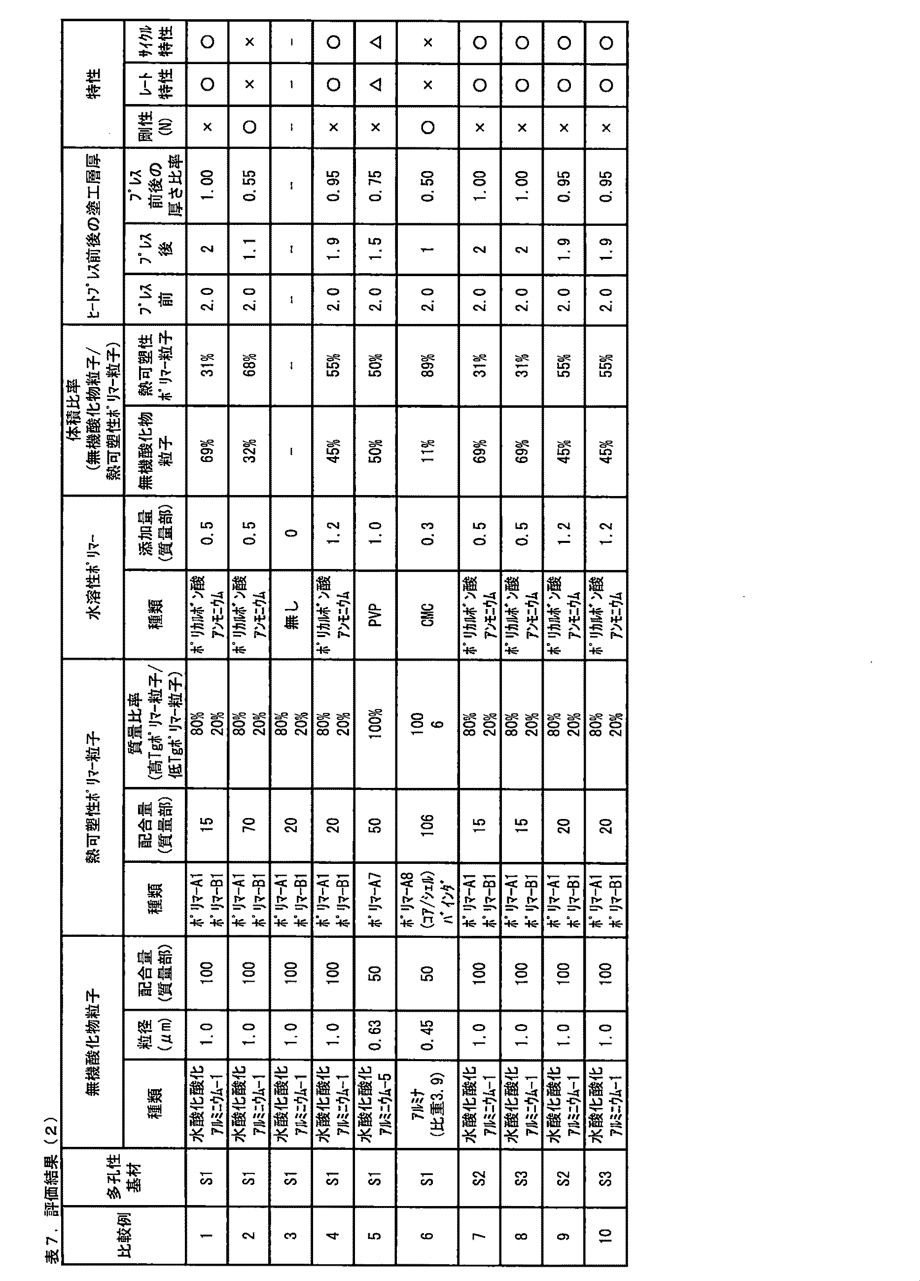
アミド結合含有環状構造を有する基と重合性二重結合とを有するモノマーと共重合可能なモノマーとしては、ビニル非環状アミド類;(メタ)アクリル酸及びそのエステル類;(メタ)アクリルアミド及びその誘導体;スチレン及びその誘導体;酢酸ビニル等のビニルエステル類;α−オレフィン類;ビニルイミダゾール、ビニルピリジン等の塩基性不飽和化合物及びその誘導体;カルボキシル基含有不飽和化合物及びその酸無水物;ビニルスルホン酸及びその誘導体;ビニルエチレンカーボネート及びその誘導体;並びにビニルエーテル類が挙げられる。 Examples of the monomer copolymerizable with the monomer having a group having an amide bond-containing cyclic structure and a polymerizable double bond include vinyl acyclic amides; (meth)acrylic acid and its esters; (meth)acrylamide and its derivatives. Styrene and its derivatives; vinyl esters such as vinyl acetate; α-olefins; basic unsaturated compounds such as vinylimidazole and vinylpyridine and their derivatives; unsaturated compounds containing a carboxyl group and their acid anhydrides; vinyl sulfonic acid And its derivatives; vinyl ethylene carbonate and its derivatives; and vinyl ethers.
本実施形態では、熱可塑性層中の水溶性ポリマーの含有量が、無機酸化物粒子と熱可塑性ポリマーの合計質量に対して0.04質量%以上1.0質量%未満である。この含有量は、無機フィラー及び熱可塑性ポリマーを含む樹脂組成物を塗布液として、特に水系塗料として形成するために必要な水溶性ポリマーの量として0.04質量%以上である。一方で、この含有量は、熱可塑性層において水溶性ポリマーが熱可塑性ポリマーの表面を部分的に覆うことによって、電解液中で熱可塑性ポリマーを適度に膨潤させるという観点から1.0質量%未満である。この含有量は、好ましくは0.05質量%以上0・9質量%以下、より好ましくは0.1質量%以上0.85質量%以下、さらに好ましくは0.2質量%以上0.8質量%以下である。 In the present embodiment, the content of the water-soluble polymer in the thermoplastic layer is 0.04 mass% or more and less than 1.0 mass% with respect to the total mass of the inorganic oxide particles and the thermoplastic polymer. This content is 0.04 mass% or more as the amount of the water-soluble polymer necessary for forming a resin composition containing an inorganic filler and a thermoplastic polymer as a coating liquid, particularly as a water-based paint. On the other hand, this content is less than 1.0% by mass from the viewpoint that the water-soluble polymer partially covers the surface of the thermoplastic polymer in the thermoplastic layer, so that the thermoplastic polymer is appropriately swollen in the electrolytic solution. Is. This content is preferably 0.05% by mass or more and 0.9% by mass or less, more preferably 0.1% by mass or more and 0.85% by mass or less, and further preferably 0.2% by mass or more and 0.8% by mass. It is as follows.
(添加剤)
本実施形態では、熱可塑性層が、無機フィラー、熱可塑性ポリマー及び水溶性ポリマーのみから成っていてもよいし、無機フィラー、熱可塑性ポリマー及び水溶性ポリマー以外の添加剤を含んでいてもよい。添加剤としては、例えば、上記で説明された水溶性ポリマー以外の低分子量分散剤;増粘剤;及び水酸化アンモニウム等のpH調整剤が挙げられる。低分子量分散剤の具体例としては、カルボン酸のアンモニウム塩又はアルカリ金属塩を複数有するモノマー(Cii)、カルボン酸のアンモニウム塩又はアルカリ金属塩を複数有する非重合性化合物(例えば、アルギン酸ソーダ、及びヒアルロン酸ソーダ)等が挙げられる。
(Additive)
In the present embodiment, the thermoplastic layer may be composed only of the inorganic filler, the thermoplastic polymer and the water-soluble polymer, or may contain an additive other than the inorganic filler, the thermoplastic polymer and the water-soluble polymer. Examples of the additives include low molecular weight dispersants other than the water-soluble polymers described above; thickeners; and pH adjusters such as ammonium hydroxide. Specific examples of the low molecular weight dispersant include monomers (C ii ) having a plurality of ammonium salts or alkali metal salts of carboxylic acids, non-polymerizable compounds having a plurality of ammonium salts or alkali metal salts of carboxylic acids (for example, sodium alginate, And sodium hyaluronate) and the like.
[熱可塑性層の配置方法]
多孔性基材上に熱可塑性層を配置する方法の一態様は、無機フィラー、熱可塑性ポリマー、水溶性ポリマー及び所望により添加剤を含む塗布液を多孔性基材に塗布する工程を含む。
[Arrangement Method of Thermoplastic Layer]
One embodiment of the method of disposing the thermoplastic layer on the porous substrate includes a step of applying a coating liquid containing an inorganic filler, a thermoplastic polymer, a water-soluble polymer and optionally additives to the porous substrate.
塗布液としては、熱可塑性ポリマーを、熱可塑性ポリマーが溶解しない溶媒中に分散させた分散体を好ましく用いることができる。熱可塑性ポリマーを乳化重合によって合成し、乳化重合によって得られるエマルジョンをそのまま塗布液として使用することが好ましい。 As the coating liquid, a dispersion prepared by dispersing a thermoplastic polymer in a solvent in which the thermoplastic polymer is insoluble can be preferably used. It is preferable to synthesize a thermoplastic polymer by emulsion polymerization and use the emulsion obtained by emulsion polymerization as it is as a coating liquid.
多孔性基材上に塗布液を塗布する方法としては、所望の塗布パターン、塗布膜厚、及び塗布面積を実現できる方法であれば特に限定されないが、例えば、グラビアコーター法、小径グラビアコーター法、リバースロールコーター法、トランスファロールコーター法、キスコーター法、ディップコーター法、ナイフコーター法、エアドクタコーター法、ブレードコーター法、ロッドコーター法、スクイズコーター法、キャストコーター法、ダイコーター法、スクリーン印刷法、スプレー塗布法、インクジェット塗布法等が挙げられる。中でも、熱可塑性ポリマーの塗工形状の自由度が高く、かつ好ましい面積割合を容易に得られるという観点から、グラビアコーター法又はスプレー塗布法が好ましい。 The method of applying the coating liquid on the porous substrate is not particularly limited as long as it is a method capable of realizing a desired coating pattern, coating film thickness, and coating area, for example, a gravure coater method, a small diameter gravure coater method, Reverse roll coater method, transfer roll coater method, kiss coater method, dip coater method, knife coater method, air doctor coater method, blade coater method, rod coater method, squeeze coater method, cast coater method, die coater method, screen printing method, A spray coating method, an inkjet coating method and the like can be mentioned. Among them, the gravure coater method or the spray coating method is preferable from the viewpoint that the flexibility of the coating shape of the thermoplastic polymer is high and a preferable area ratio can be easily obtained.
塗布液の媒体としては、熱可塑性ポリマーの貧溶媒を使用することが好ましい。このような媒体としては、水、又は水と水溶性有機媒体の混合溶媒が好ましい。水溶性有機媒体としては、例えば、エタノール、メタノール等を挙げることができる。これらの中でも水がより好ましい。一般に、塗布液を基材に塗布する際に、塗布液が基材の内部にまで入り込んでしまうと、コポリマーを含む熱可塑性ポリマーが、基材の孔の表面及び内部を閉塞し透過性が低下し易くなる。これに対して、塗布液の溶媒又は分散媒として水を用いる場合には、基材の内部に塗布液が入り込み難くなり、コポリマーを含む熱可塑性ポリマーが概ね基材の外表面上に存在し易くなるため、透過性の低下をより効果的に抑制できるので好ましい。 As a medium for the coating liquid, it is preferable to use a poor solvent for the thermoplastic polymer. As such a medium, water or a mixed solvent of water and a water-soluble organic medium is preferable. Examples of the water-soluble organic medium include ethanol and methanol. Of these, water is more preferable. Generally, when the coating liquid enters the inside of the substrate when the coating liquid is applied to the substrate, the thermoplastic polymer containing the copolymer blocks the surface and the inside of the pores of the substrate to reduce the permeability. Easier to do. On the other hand, when water is used as the solvent or dispersion medium for the coating liquid, the coating liquid is less likely to enter the inside of the base material, and the thermoplastic polymer containing the copolymer is likely to be present on the outer surface of the base material. Therefore, the decrease in permeability can be suppressed more effectively, which is preferable.
塗布に先立ち、多孔性基材の表面に表面処理を施しておくと、塗布液を塗布し易くなると共に、多孔性基材と熱可塑性ポリマーとの接着性が向上するため好ましい。表面処理の方法としては、例えば、コロナ放電処理法、プラズマ処理法、機械的粗面化法、溶剤処理法、酸処理法、紫外線酸化法等が挙げられる。 It is preferable to subject the surface of the porous substrate to a surface treatment prior to coating, because the coating liquid can be easily coated and the adhesion between the porous substrate and the thermoplastic polymer is improved. Examples of the surface treatment method include a corona discharge treatment method, a plasma treatment method, a mechanical surface roughening method, a solvent treatment method, an acid treatment method, and an ultraviolet oxidation method.
塗布後に塗布膜から溶媒を除去する方法については、多孔性基材又は熱可塑性層に悪影響を及ぼさない方法であれば特に限定はない。例えば、多孔性基材を固定しながらその融点以下の温度にて乾燥する方法、低温で減圧乾燥する方法、熱可塑性ポリマーに対する貧溶媒に浸漬して熱可塑性ポリマーを粒子状に凝固させると同時に溶媒を抽出する方法等が挙げられる。 The method of removing the solvent from the coating film after coating is not particularly limited as long as it does not adversely affect the porous substrate or the thermoplastic layer. For example, a method of drying the porous substrate at a temperature below its melting point while fixing it, a method of drying under reduced pressure at a low temperature, a method of immersing in a poor solvent for the thermoplastic polymer to coagulate the thermoplastic polymer into particles, and at the same time a solvent And a method of extracting
<蓄電デバイス用セパレータ>
本実施形態に係る蓄電デバイス用セパレータは、多孔性基材上に特定の熱可塑性層を備えており、イオン透過性、及び電極活物質との接着性、特に電極と共にプレスされた時の電極活物質との接着性に優れる。
<Separator for electricity storage device>
The electricity storage device separator according to the present embodiment is provided with a specific thermoplastic layer on a porous base material, and has ion permeability, and adhesiveness with an electrode active material, particularly electrode activity when pressed with an electrode. Excellent adhesion to substances.
本実施形態に係る蓄電デバイス用セパレータは、これを電極と重ね合わせて電解液で濡らし、プレス温度100℃、プレス圧力1.0MPa、プレス時間2分間の条件でプレスをした際の剥離強度が2N/m以上であることが好ましい。電解液としては、エチレンカーボネート(EC)とジエチルカーボネート(DEC)の混合溶媒(EC体積:DEC体積=2:3)にLiPF6を1mol/L含んだものを使用する。これは本実施形態に係るセパレータが電極に対する接着性を有していることを意味する。剥離強度をこの範囲に設定することにより、セパレータと電極の接着性が十分に確保され、充放電による電極の膨張収縮に伴うセパレータと電極の間の剥がれ、及び電池厚みの増大を抑制できる。その結果、均一なリチウムイオンの行き来を可能にし、リチウムデンドライトの発生を抑えて、良好なサイクル特性が達成される。 The separator for an electricity storage device according to this embodiment has a peel strength of 2N when pressed under the conditions of a temperature of 100° C., a pressure of 1.0 MPa, and a pressing time of 2 minutes, which is superposed on an electrode and wetted with an electrolytic solution. /M or more is preferable. As the electrolytic solution, a mixed solvent of ethylene carbonate (EC) and diethyl carbonate (DEC) (EC volume:DEC volume=2:3) containing 1 mol/L of LiPF 6 is used. This means that the separator according to this embodiment has adhesiveness to the electrodes. By setting the peeling strength within this range, sufficient adhesiveness between the separator and the electrode can be ensured, and peeling between the separator and the electrode due to expansion and contraction of the electrode due to charge/discharge and an increase in battery thickness can be suppressed. As a result, it is possible to uniformly transfer lithium ions, suppress the generation of lithium dendrites, and achieve good cycle characteristics.
上記の剥離強度の測定に用いる電極は、正極と負極のいずれでもよいが、本実施形態に係る蓄電デバイス用セパレータの効果を適切に把握するためには、正極であることが好ましい。正極集電体上に、正極活物質を含む正極活物質層が形成されたリチウムイオン二次電池用正極を、前記正極活物質層がセパレータの熱可塑性層形成面と相対するように重ね合わせ、上記のようにロールプレスしてから剥離強度を測定することが適切である。 The electrode used for measuring the peel strength may be either a positive electrode or a negative electrode, but the positive electrode is preferable in order to properly understand the effect of the separator for an electricity storage device according to the present embodiment. On the positive electrode current collector, a positive electrode active material layer containing a positive electrode active material positive electrode for a lithium ion secondary battery, the positive electrode active material layer is laminated so as to face the thermoplastic layer forming surface of the separator, It is appropriate to measure the peel strength after roll pressing as described above.
本実施形態に係る蓄電デバイス用セパレータの透気度は、好ましくは10〜10,000秒/100ccであり、より好ましくは10〜1,000秒/100ccであり、更に好ましくは50〜500秒/100ccである。これにより、セパレータをリチウムイオン二次電池に適用したときには、大きなイオン透過性を示す。この透気度は、多孔性基材の透気度と同様に、JIS P−8117に準拠して測定される透気抵抗度である。 The air permeability of the electricity storage device separator according to the present embodiment is preferably 10 to 10,000 seconds/100 cc, more preferably 10 to 1,000 seconds/100 cc, and further preferably 50 to 500 seconds/. It is 100 cc. As a result, when the separator is applied to a lithium ion secondary battery, it exhibits large ion permeability. The air permeability is the air resistance measured in accordance with JIS P-8117, like the air permeability of the porous substrate.
<蓄電デバイス>
本実施形態に係る蓄電デバイス用セパレータを備える蓄電デバイスは、特に限定されないが、例えば、非水系電解液二次電池等の電池、コンデンサー及びキャパシタが挙げられる。それらの中でも、本発明の作用効果による利益がより有効に得られる観点から、電池が好ましく、非水系電解液二次電池がより好ましく、リチウムイオン二次電池が更に好ましい。
<Power storage device>
The electricity storage device including the electricity storage device separator according to the present embodiment is not particularly limited, and examples thereof include batteries such as non-aqueous electrolyte secondary batteries, capacitors, and capacitors. Among them, the battery is preferable, the non-aqueous electrolyte secondary battery is more preferable, and the lithium ion secondary battery is still more preferable, from the viewpoint of more effectively obtaining the benefit of the action and effect of the present invention.
本実施形態に係る蓄電デバイスの構成は、上記で説明された蓄電デバイス用セパレータを備えること以外は、従来知られている通りでよい。蓄電デバイスがリチウムイオン二次電池等の非水系電解液二次電池である場合についての好適な態様を以下に説明する。 The configuration of the electricity storage device according to the present embodiment may be as conventionally known, except that the electricity storage device separator described above is provided. A preferred embodiment in the case where the electricity storage device is a non-aqueous electrolyte secondary battery such as a lithium ion secondary battery will be described below.
本実施形態に係るセパレータを用いてリチウムイオン二次電池を製造する場合、正極、負極、及び非水電解液に限定はなく、それぞれ既知のものを用いることができる。
正極としては、正極集電体上に正極活物質を含む正極活物質層が形成されて成る正極を好適に用いることができる。正極集電体としては、例えばアルミニウム箔等を;正極活物質としては、例えば、LiCoO2、LiNiO2、スピネル型LiMnO4、オリビン型LiFePO4等のリチウム含有複合酸化物等を;それぞれ挙げることができる。正極活物質層は、正極活物質に加えて、バインダ、導電材等を含んでいてもよい。
When a lithium ion secondary battery is manufactured using the separator according to this embodiment, the positive electrode, the negative electrode, and the non-aqueous electrolytic solution are not limited, and known ones can be used.
As the positive electrode, a positive electrode in which a positive electrode active material layer containing a positive electrode active material is formed on a positive electrode current collector can be preferably used. Examples of the positive electrode current collector include aluminum foil and the like; examples of the positive electrode active material include lithium-containing composite oxides such as LiCoO 2 , LiNiO 2 , spinel type LiMnO 4 , and olivine type LiFePO 4. it can. The positive electrode active material layer may include a binder, a conductive material, and the like in addition to the positive electrode active material.
負極としては、負極集電体上に負極活物質を含む負極活物質層が形成されて成る負極を好適に用いることができる。負極集電体としては、例えば銅箔等を;負極活物質としては、例えば、黒鉛質、難黒鉛化炭素質、易黒鉛化炭素質、複合炭素体等の炭素材料;シリコン、スズ、金属リチウム、各種合金材料等を;それぞれ挙げることができる。 As the negative electrode, a negative electrode formed by forming a negative electrode active material layer containing a negative electrode active material on a negative electrode current collector can be preferably used. As the negative electrode current collector, for example, copper foil or the like; as the negative electrode active material, for example, carbon material such as graphite, non-graphitizable carbonaceous material, easily graphitizable carbonaceous material, composite carbon body; silicon, tin, metallic lithium , Various alloy materials and the like;
非水電解液としては、特に限定されないが、電解質を有機溶媒に溶解した電解液を用いることができる。有機溶媒としては、例えば、プロピレンカーボネート、エチレンカーボネート、ジメチルカーボネート、ジエチルカーボネート、エチルメチルカーボネート等が挙げられる。電解質としては、例えば、LiClO4、LiBF4、LiPF6等のリチウム塩が挙げられる。 The non-aqueous electrolytic solution is not particularly limited, but an electrolytic solution in which an electrolyte is dissolved in an organic solvent can be used. Examples of the organic solvent include propylene carbonate, ethylene carbonate, dimethyl carbonate, diethyl carbonate, ethyl methyl carbonate and the like. Examples of the electrolyte include lithium salts such as LiClO 4 , LiBF 4 , and LiPF 6 .
本実施形態に係る蓄電デバイス用セパレータを用いて蓄電デバイスを製造する方法を以下に例示する。
本実施形態に係るセパレータを、幅10〜500mm(好ましくは80〜500mm)、長さ200〜4,000m(好ましくは1,000〜4,000m)の縦長形状のセパレータとして製造し、セパレータを、正極−セパレータ−負極−セパレータ、又は負極−セパレータ−正極−セパレータの順で積層し、円又は扁平な渦巻状に捲回して捲回体を得、捲回体を電池缶内に収納し、更に電解液を注入することにより、蓄電デバイスを製造することができる。代替的には、シート状のセパレータ及び電極から成る積層体(例えば正極−セパレータ−負極−セパレータ−正極、又は負極−セパレータ−正極−セパレータ−負極の順に平板状に積層したもの)、又は電極及びセパレータを折り畳んで捲回体としたものを、電池容器(例えばアルミニウム製のフィルム)に入れて、電解液を注液する方法によって製造してもよい。
A method for manufacturing an electricity storage device using the electricity storage device separator according to the present embodiment will be exemplified below.
The separator according to the present embodiment is manufactured as a vertically elongated separator having a width of 10 to 500 mm (preferably 80 to 500 mm) and a length of 200 to 4,000 m (preferably 1,000 to 4,000 m). Positive electrode-separator-negative electrode-separator, or negative electrode-separator-positive electrode-separator are laminated in this order and wound into a circular or flat spiral to obtain a wound body, and the wound body is housed in a battery can. An electric storage device can be manufactured by injecting the electrolytic solution. Alternatively, a laminate composed of a sheet-shaped separator and an electrode (for example, a positive electrode-separator-negative electrode-separator-positive electrode, or a negative electrode-separator-positive electrode-separator-negative electrode laminated in the order of a flat plate), or The separator may be folded into a wound body, and the wound body may be put into a battery container (for example, a film made of aluminum) and the electrolytic solution may be injected.
いずれの場合にも、積層体又は捲回体に対して、プレスを行うことができる。具体的には、本実施形態に係る蓄電デバイス用セパレータと、集電体及び集電体の少なくとも片面上に形成された活物質層を有する電極とを、セパレータの熱可塑性層と電極の活物質層とが対向するように重ね合わせてプレスを行う方法を例示することができる。 In any case, pressing can be performed on the laminate or the wound body. Specifically, the electricity storage device separator according to the present embodiment, and a current collector and an electrode having an active material layer formed on at least one surface of the current collector, a thermoplastic layer of the separator and an active material of the electrode. It is possible to exemplify a method of stacking and pressing so that the layers face each other.
プレス温度は、効果的に接着性を発現できる温度として、例えば20℃以上が好ましい。また熱プレスによるセパレータ孔の目詰まり又は熱収縮を抑える点で、プレス温度は、ポリオレフィン多孔性基材の融点よりも低いことが好ましく、120℃以下がさらに好ましい。プレス圧力は、セパレータ孔の目詰まりを抑える観点から20MPa以下が好ましい。プレス時間については、ロールプレスを用いたときに1秒以下でもよく、数時間の面プレスでもよい。本実施形態に係る蓄電デバイス用セパレータを用いて、上記の製造工程を経ると、電極及びセパレータから成る捲回体をプレス成形した際のプレスバックを抑制できる。シート状電極及びシート状セパレータから成る積層体をプレス成形した後の、剥がれ及び位置ズレを防ぐこともできる。したがって、電池組立工程における歩留まり低下を抑制し、生産工程時間を短縮することができるので、上記の製造工程は好ましい。 The pressing temperature is preferably, for example, 20° C. or higher as a temperature at which adhesiveness can be effectively exhibited. In addition, the pressing temperature is preferably lower than the melting point of the polyolefin porous substrate, and more preferably 120° C. or lower, from the viewpoint of suppressing clogging of separator holes or thermal shrinkage due to hot pressing. The pressing pressure is preferably 20 MPa or less from the viewpoint of suppressing clogging of separator holes. The pressing time may be 1 second or less when a roll press is used, or a surface press for several hours. When the electricity storage device separator according to the present embodiment is used and the above manufacturing process is performed, it is possible to suppress pressback when the wound body including the electrode and the separator is press-molded. It is also possible to prevent peeling and misalignment after press-molding a laminated body including a sheet-shaped electrode and a sheet-shaped separator. Therefore, it is possible to suppress a decrease in yield in the battery assembly process and shorten the production process time, and thus the above-described manufacturing process is preferable.
上記で説明された積層体又は捲回体に対して電解液を注液した後に、熱プレスを行うこともできる。その場合、プレス温度としては、効果的に接着性を発現できる温度として、例えば20℃以上が好ましく、熱プレスによるセパレータ孔の目詰まり又は熱収縮を抑える観点から120℃以下が好ましい。プレス圧力はセパレータ孔の目詰まりを抑える観点から20MPa以下が好ましい。プレス時間は生産性の観点から2時間以下が好ましい。 It is also possible to perform hot pressing after injecting the electrolytic solution into the laminate or wound body described above. In that case, the pressing temperature is preferably 20° C. or higher as the temperature at which adhesiveness can be effectively exhibited, and is preferably 120° C. or lower from the viewpoint of suppressing clogging of separator holes or thermal shrinkage due to hot pressing. The pressing pressure is preferably 20 MPa or less from the viewpoint of suppressing clogging of separator holes. The pressing time is preferably 2 hours or less from the viewpoint of productivity.
上記のようにして製造されたリチウムイオン二次電池等の蓄電デバイスは、高い接着性を有し、かつイオン抵抗を低減させたセパレータを具備するため、剛性と電池特性(レート特性)と長期連続稼動耐性(サイクル特性)に優れる。 The electricity storage device such as the lithium-ion secondary battery manufactured as described above has a separator having a high adhesive property and a reduced ionic resistance, so that the rigidity, the battery characteristics (rate characteristics), and the long-term continuity are maintained. Excellent operation resistance (cycle characteristics).
以下、本発明を実施例及び比較例に基づいて詳細に説明をするが、本発明は実施例に限定されるものではない。以下の製造例、実施例、及び比較例における各種物性の測定方法及び評価方法は、それぞれ、以下のとおりである。特に記載のない限り、各種の測定及び評価を、室温23℃、1気圧、及び相対湿度50%の条件下で行った。 Hereinafter, the present invention will be described in detail based on Examples and Comparative Examples, but the present invention is not limited to the Examples. The methods for measuring and evaluating various physical properties in the following Production Examples, Examples, and Comparative Examples are as follows, respectively. Unless otherwise specified, various measurements and evaluations were performed under the conditions of room temperature of 23° C., 1 atmospheric pressure, and relative humidity of 50%.
<測定方法>
(1)固形分
試料をアルミ皿上に約1g精秤し、このとき量り取った試料の質量をa(g)とした。それを、130℃の熱風乾燥機で1時間乾燥し、乾燥後の試料の乾燥質量をb(g)とした。下記式により固形分を算出した。
固形分=(b/a)×100 [%]
<Measurement method>
(1) Solid content About 1 g of a sample was precisely weighed on an aluminum dish, and the mass of the sample weighed at this time was defined as a(g). It was dried for 1 hour with a hot air dryer at 130° C., and the dry mass of the dried sample was defined as b(g). The solid content was calculated by the following formula.
Solid content=(b/a)×100 [%]
(2)粒子径の測定
試料の平均粒径を、粒子径測定装置(日機装株式会社製、Microtrac UPA150)を使用し、測定した。測定条件としては、ローディングインデックス=0.15〜0.3、測定時間300秒とし、得られたデータにおける50%粒子径の数値を粒子径として記載した。
(2) Measurement of particle diameter The average particle diameter of the sample was measured using a particle diameter measuring device (Microtrac UPA150, manufactured by Nikkiso Co., Ltd.). The measurement conditions were a loading index of 0.15 to 0.3 and a measurement time of 300 seconds, and the numerical value of 50% particle diameter in the obtained data was described as the particle diameter.
(3)電解液に対する膨潤度
ポリマー又はポリマー分散液を130℃のオーブン中に1時間静置した後、乾燥させたポリマーを重量が0.5gになるように切り取り、エチレンカーボネート:ジエチルカーボネート=2:3(質量比)の混合溶媒10gと共に50mLのバイアル瓶に入れた。バイアル瓶中のサンプルを3時間浸透させた後、サンプルを取り出し、上記混合溶媒にて洗浄し、重量(Wa)を測定した。サンプルを150℃のオーブン中に1時間静置した後、重量(Wb)を測定し、下記式でポリマーの電解液に対する膨潤度を測定した。
熱可塑性ポリマーの電解液に対する膨潤度(倍)=(Wa−Wb)÷(Wb)
(3) Swelling degree to electrolyte solution After allowing the polymer or polymer dispersion solution to stand in an oven at 130° C. for 1 hour, the dried polymer was cut to a weight of 0.5 g, and ethylene carbonate:diethyl carbonate=2. : 3 (mass ratio) of the mixed solvent was put in a 50 mL vial. After allowing the sample in the vial to permeate for 3 hours, the sample was taken out, washed with the above mixed solvent, and the weight (W a ) was measured. After allowing the sample to stand in an oven at 150° C. for 1 hour, the weight (W b ) was measured, and the swelling degree of the polymer with respect to the electrolytic solution was measured by the following formula.
Degree of swelling electrolyte of the thermoplastic polymer (times) = (W a -W b) ÷ (W b)
(4)ガラス転移温度の測定
熱可塑性ポリマー粒子を含む水分散体(固形分=38〜42質量%、pH=9.0)を、アルミ皿に適量取り、130℃の熱風乾燥機で30分間乾燥した。乾燥後の乾燥皮膜約17mgを測定用アルミ容器に詰め、DSC測定装置(島津製作所社製、DSC6220)にて窒素雰囲気下におけるDSC曲線及びDDSC曲線を得た。測定条件は下記の通りとした。
1段目昇温プログラム:70℃スタート、毎分15℃の割合で昇温。110℃に到達後5分間維持。
2段目降温プログラム:110℃から毎分40℃の割合で降温。−50℃に到達後5分間維持。
3段目昇温プログラム:−50℃から毎分15℃の割合で130℃まで昇温。この3段目の昇温時にDSC及びDDSCのデータを取得。
ベースライン(得られたDSC曲線におけるベースラインを高温側に延長した直線)と、変曲点(上に凸の曲線が下に凸の曲線に変わる点)における接線との交点をガラス転移温度(Tg)とした。
(4) Measurement of glass transition temperature An appropriate amount of an aqueous dispersion (solid content=38 to 42 mass%, pH=9.0) containing thermoplastic polymer particles is placed in an aluminum dish, and a hot air dryer at 130° C. is used for 30 minutes. Dried. About 17 mg of the dried film after drying was packed in an aluminum container for measurement, and a DSC curve and a DDSC curve under a nitrogen atmosphere were obtained with a DSC measuring device (manufactured by Shimadzu Corporation, DSC6220). The measurement conditions were as follows.
1st stage heating program: 70°C start, heating at a rate of 15°C/min. Hold for 5 minutes after reaching 110°C.
Second stage cooling program: 110°C to 40°C/min. Hold for 5 minutes after reaching -50°C.
3rd stage heating program: Temperature rising from -50°C to 130°C at a rate of 15°C per minute. Data of DSC and DDSC were acquired when the temperature was raised in the third step.
The intersection of the baseline (a straight line obtained by extending the baseline in the obtained DSC curve to the high temperature side) and the tangent at the inflection point (the point where the upward convex curve changes to the downward convex curve) is taken to be the glass transition temperature ( Tg).
(5)粘度平均分子量Mv
ASRM−D4020に準拠して、デカリン溶剤中、135℃における極限粘度[η]を求めた。この[η]値を用いて、下記数式の関係から粘度平均分子量Mvを算出した。
ポリエチレンの場合:[η]=0.00068×Mv0.67
ポリプロピレンの場合:[η]=1.10×Mv0.80
(5) Viscosity average molecular weight Mv
In accordance with ASRM-D4020, the intrinsic viscosity [η] at 135°C in a decalin solvent was determined. Using this [η] value, the viscosity average molecular weight Mv was calculated from the relationship of the following mathematical formula.
In the case of polyethylene: [η]=0.00068×Mv0.67
In the case of polypropylene: [η]=1.10×Mv0.80
(6)膜厚(μm)
基材から10cm×10cm角の試料を切り取り、格子状に9箇所(3点×3点)を選んで、微小測厚器(株式会社東洋精機製作所 タイプKBM)を用いて室温23±2℃で膜厚を測定した。得られた9箇所の測定値の平均値を、基材の膜厚として算出した。
(6) Film thickness (μm)
Cut out a 10 cm x 10 cm square sample from the base material, select 9 points (3 points x 3 points) in a grid pattern, and use a micro thickness gauge (Toyo Seiki Seisakusho Type KBM) at room temperature 23 ± 2°C. The film thickness was measured. The average value of the obtained measured values at 9 points was calculated as the film thickness of the substrate.
(7)気孔率
基材から10cm×10cm角のサンプルを切り取り、その体積(cm3)及び質量(g)を求めた。これらの値を用い、基材の密度を0.95(g/cm3)として、気孔率を下記数式:
気孔率(%)=(1−質量/体積/0.95)×100
により計算した。
(7) Porosity A 10 cm×10 cm square sample was cut out from the base material, and its volume (cm 3 ) and mass (g) were determined. Using these values, the density of the substrate is set to 0.95 (g/cm 3 ), and the porosity is calculated by the following mathematical formula:
Porosity (%)=(1-mass/volume/0.95)×100
Calculated by
(8)透気度(秒/100cc)
JIS P−8117に準拠し、東洋精器(株)製のガーレー式透気度計G−B2(商標)により測定した透気抵抗度を透気度とした。
(8) Air permeability (sec/100cc)
Based on JIS P-8117, the air permeability resistance was measured by a Gurley type air permeability meter G-B2 (trademark) manufactured by Toyo Seiki Co., Ltd.
(9)突刺強度(g)
カトーテック製のハンディー圧縮試験器KES−G5(商標)を用いて、開口部の直径11.3mmの試料ホルダーで基材を固定した。次に、固定された基材の中央部を、先端の曲率半径0.5mmの針を用いて、突刺速度2mm/秒で、25℃雰囲気下において突刺試験を行うことにより、最大突刺荷重として突刺強度(g)を得た。
(9) Puncture strength (g)
The base material was fixed with a sample holder having a diameter of 11.3 mm at the opening using a handy compression tester KES-G5 (trademark) manufactured by Kato Tech. Next, the center portion of the fixed base material is subjected to a puncture test in a 25° C. atmosphere at a puncture speed of 2 mm/sec using a needle having a curvature radius of 0.5 mm at the tip to puncture as a maximum puncture load. The strength (g) was obtained.
(10)電解液浸漬サンプルのヒートプレス後の厚さ
セパレータ及びアルミニウム箔(UACJ製箔、合金番号1085、厚さ:20μm)を幅20mm、長さ40mmにカットした。セパレータとアルミニウム箔を重ねた後、エチレンカーボネート(EC)とジエチルカーボネート(DEC)の混合物(EC体積/DEC体積=2/3、LiPF6濃度:1M、混合物としてのSP値=11.6)をセパレータが浸る程度にたらした。この積層体をアルミラミネートフィルム(昭和電工製、商標SPAL)に入れ四隅を加熱シーラーで封しした後、80℃、1.0MPaの条件で、60分間プレスを行った後、積層体を取り出し、エタノールで洗浄して、セパレータサンプルを得た。
(10) Thickness of Electrolytic Solution Immersed Sample After Heat Press A separator and an aluminum foil (UACJ foil, alloy number 1085, thickness: 20 μm) were cut into a width of 20 mm and a length of 40 mm. After stacking the separator and the aluminum foil, a mixture of ethylene carbonate (EC) and diethyl carbonate (DEC) (EC volume/DEC volume=2/3, LiPF 6 concentration: 1M, SP value as mixture=11.6) The separator was soaked. This laminate was placed in an aluminum laminate film (trade name SPAL manufactured by Showa Denko), the four corners were sealed with a heating sealer, and then pressed at 80° C. and 1.0 MPa for 60 minutes, and then the laminate was taken out. A separator sample was obtained by washing with ethanol.
ブロードイオンビーム(BIB)により、洗浄した積層体の断面加工を行った。加工の際、熱ダメージを抑制するために必要に応じてサンプルを直前まで冷却させた。具体的には、−40℃の冷却装置にセパレータサンプルを一昼夜放置した。これにより、平滑なセパレータ断面が得られた。得られたセパレータ断面を、Cペースト及びOsコーティングにより、導通処理を行った後、「HITACHI S−4700」(日立ハイテクフィールディング社製)を用いて撮影を行い、得られた断面SEM像から、ヒートプレス後の塗工層の厚さ(Ta)を測定した。 The cross section of the washed laminate was processed by a broad ion beam (BIB). During processing, the sample was allowed to cool to just before to prevent thermal damage. Specifically, the separator sample was left to stand overnight in a cooling device at -40°C. As a result, a smooth separator cross section was obtained. The obtained separator cross-section was subjected to conduction treatment with C paste and Os coating, and then photographed using "HITACHI S-4700" (manufactured by Hitachi High-Tech Fielding), and the obtained cross-section SEM image was used for heat treatment. The thickness ( Ta ) of the coating layer after pressing was measured.
ヒートプレス前のセパレータについても同様にBIBで断面加工を行った後の断面SEM像からヒートプレス前の塗工層の厚さ(Tb)を測定した。 Similarly, for the separator before heat pressing, the thickness (T b ) of the coating layer before heat pressing was measured from the cross-sectional SEM image after the cross-section processing was performed with BIB.
(11)セル剛性評価法
アルミラミネート(昭和電工パッケージング株式会社製:St ON25/AL40/OPP40)を幅60mm、長さ80mmにカットして、ヒートシーラーで3辺を封止して、収納体を得た。
(11) Cell rigidity evaluation method Aluminum laminate (St ON25/AL40/OPP40 manufactured by Showa Denko Packaging Co., Ltd.) was cut into a width of 60 mm and a length of 80 mm, and three sides were sealed with a heat sealer, and a storage body Got
正極(enertech社製、正極材料:LiCoO2、正極電位:4.35V、L/W:両側について36mg/cm2、密度:3.9g/cc)と、実施例又は比較例で調製されたセパレータとを、それぞれ、幅30mm、長さ180mmにカットし、カットされた正極及びセパレータを重ねて積層体を得た。 Positive electrode (manufactured by enertech, positive electrode material: LiCoO 2 , positive electrode potential: 4.35 V, L/W: 36 mg/cm 2 on both sides, density: 3.9 g/cc) and a separator prepared in Examples or Comparative Examples Were cut into a width of 30 mm and a length of 180 mm, and the cut positive electrode and separator were stacked to obtain a laminate.
積層体を、捲回回数3周の条件下で、長さが約27mmになり、かつ幅が30mmになるように捲回して、捲回体を得た。
上記で作製した収納体に捲回体を入れ、さらに電解液として、エチレンカーボネート(EC)とジエチルカーボネート(DEC)の混合物(EC体積/DEC体積=2/3、LiPF6濃度:1M、混合物としてのSP値=11.6)を0.5ml入れ、ヒートシーラーで封止して、12時間静置して、被プレス体を得た。
温度80℃及び圧力1MPaの条件下で、被プレス体を60分間プレスして、プレス体を得た。
The laminated body was wound under the condition that the number of windings was 3 times so that the length was about 27 mm and the width was 30 mm to obtain a wound body.
The wound body was placed in the container prepared above, and as an electrolyte, a mixture of ethylene carbonate (EC) and diethyl carbonate (DEC) (EC volume/DEC volume=2/3, LiPF 6 concentration: 1M, as a mixture). 0.5 ml of SP value=11.6) was sealed, sealed with a heat sealer, and allowed to stand for 12 hours to obtain a pressed body.
The pressed body was pressed for 60 minutes under conditions of a temperature of 80° C. and a pressure of 1 MPa to obtain a pressed body.
突刺し治具(A型A−4)を備えるデジタルフォースゲージ「DS2−50N」(製品名、株式会社イマダ製)と、切り込み部(上部の切り込み幅:約27mm、下部の切り込み幅:約15mm)を有する被突刺し台座とを、電動計測スタンド「MX2−500N」(製品名、株式会社イマダ製)に取り付けた。 Digital force gauge "DS2-50N" (product name, made by Imada Co., Ltd.) equipped with a piercing jig (A type A-4), and a notch (upper cut width: about 27 mm, lower cut width: about 15 mm) ) And the pedestal to be stabbed are attached to an electric measurement stand “MX2-500N” (product name, manufactured by Imada Co., Ltd.).
プレス体を捲回体の捲回方向に対して突刺し方向が垂直になり、かつ押し込み冶具の先端と収納体に収納された捲回体の中心とが接することができるように、被突刺し台座にセットした。 The press body is pierced so that the piercing direction is perpendicular to the winding direction of the winding body and the tip of the pressing jig can contact the center of the winding body housed in the housing body. I set it on the pedestal.
個別にセットされたプレス体を、50mm/分の曲げ速度で3点曲げ強度試験に供して、応力の極大値(N)を3点曲げ強度(剛性値)として測定した。 The individually set press bodies were subjected to a 3-point bending strength test at a bending speed of 50 mm/min, and the maximum value (N) of stress was measured as the 3-point bending strength (rigidity value).
(12)レート特性
a.正極の作製
正極活物質としてニッケル、マンガン、コバルト複合酸化物(NMC)(Ni:Mn:Co=1:1:1(元素比)、密度4.70g/cm3)を90.4質量%、導電助材としてグラファイト粉末(KS6)(密度2.26g/cm3、数平均粒子径6.5μm)を1.6質量%及びアセチレンブラック粉末(AB)(密度1.95g/cm3、数平均粒子径48nm)を3.8質量%、並びにバインダとしてポリフッ化ビニリデン(PVDF)(密度1.75g/cm3)を4.2質量%の比率で混合し、これらをN−メチルピロリドン(NMP)中に分散させてスラリーを調製した。このスラリーを、正極集電体となる厚さ20μmのアルミニウム箔の片面にダイコーターを用いて塗布し、130℃において3分間乾燥した後、ロールプレス機を用いて圧縮成形することにより、正極を作製した。この時の正極活物質塗布量は109g/m2であった。
(12) Rate characteristics a. Production of Positive Electrode 90.4% by mass of nickel, manganese, and cobalt composite oxide (NMC) (Ni:Mn:Co=1:1:1 (element ratio), density 4.70 g/cm 3 ) as a positive electrode active material, 1.6 mass% of graphite powder (KS6) (density 2.26 g/cm 3 , number average particle size 6.5 μm) and acetylene black powder (AB) (density 1.95 g/cm 3 , number average) as a conduction aid. 3.8% by mass of particle diameter 48 nm, and polyvinylidene fluoride (PVDF) (density 1.75 g/cm 3 ) as a binder were mixed in a ratio of 4.2% by mass, and these were mixed with N-methylpyrrolidone (NMP). A slurry was prepared by dispersing the slurry therein. This slurry was applied to one side of an aluminum foil having a thickness of 20 μm to be a positive electrode current collector using a die coater, dried at 130° C. for 3 minutes, and then compression-molded using a roll press machine to form a positive electrode. It was made. The amount of the positive electrode active material applied at this time was 109 g/m 2 .
b.負極の作製
負極活物質としてグラファイト粉末A(密度2.23g/cm3、数平均粒子径12.7μm)を87.6質量%及びグラファイト粉末B(密度2.27g/cm3、数平均粒子径6.5μm)を9.7質量%、並びにバインダとしてカルボキシメチルセルロースのアンモニウム塩1.4質量%(固形分換算)(固形分濃度1.83質量%水溶液)及びジエンゴム系ラテックス1.7質量%(固形分換算)(固形分濃度40質量%水溶液)を精製水中に分散させてスラリーを調製した。このスラリーを負極集電体となる厚さ12μmの銅箔の片面にダイコーターで塗布し、120℃において3分間乾燥した後、ロールプレス機で圧縮成形することにより、負極を作製した。この時の負極活物質塗布量は5.2g/m2であった。
b. Graphite powder A as prepared negative active material of the negative electrode (density 2.23 g / cm 3, number average particle diameter 12.7 [mu] m) 87.6% by weight and graphite powder B (density 2.27 g / cm 3, number average particle diameter 6.5 μm), and as a binder, 1.4% by mass of ammonium salt of carboxymethyl cellulose (as solid content) (solid content concentration 1.83% by mass aqueous solution) and 1.7% by mass of diene rubber-based latex ( A slurry was prepared by dispersing (in terms of solid content) (solid content of 40 mass% aqueous solution) in purified water. This slurry was applied to one surface of a copper foil having a thickness of 12 μm, which is a negative electrode current collector, by a die coater, dried at 120° C. for 3 minutes, and then compression-molded with a roll press machine to prepare a negative electrode. The amount of the negative electrode active material applied at this time was 5.2 g/m 2 .
c.非水電解液の調製
エチレンカーボネート:エチルメチルカーボネート=1:2(体積比)の混合溶媒に、溶質としてLiPF6を濃度1.0mol/Lとなるように溶解させることにより、非水電解液を調製した。
c. Preparation of Non-Aqueous Electrolyte Solution By dissolving LiPF 6 as a solute to a concentration of 1.0 mol/L in a mixed solvent of ethylene carbonate:ethyl methyl carbonate=1:2 (volume ratio), a non-aqueous electrolyte solution is obtained. Prepared.
d.電池組立
各実施例及び比較例で得られた蓄電デバイス用セパレータを24mmφ、正極及び負極をそれぞれ16mmφの円形に切り出した。正極と負極の活物質面とが対向するように、負極、セパレータ、正極の順に重ね、プレス又はヒートプレスをして、蓋付きステンレス金属製容器に収容した。容器と蓋とは絶縁されており、容器は負極の銅箔と、蓋は正極のアルミニウム箔と、それぞれ接していた。この容器内に前記非水電解液を0.4ml注入して密閉することにより、電池を組み立てた。
d. Battery Assembly The separator for an electricity storage device obtained in each Example and Comparative Example was cut into a circle of 24 mmφ, and each of the positive electrode and the negative electrode was cut into a circle of 16 mmφ. The negative electrode, the separator, and the positive electrode were stacked in this order such that the positive electrode and the active material surface of the negative electrode faced each other, and pressed or heat-pressed to be housed in a stainless metal container with a lid. The container and the lid were insulated, and the container was in contact with the negative electrode copper foil and the lid was in contact with the positive electrode aluminum foil, respectively. A battery was assembled by injecting 0.4 ml of the non-aqueous electrolyte into the container and sealing the container.
e.レート特性の評価
上記d.で組み立てた簡易電池を、25℃において、電流値3mA(約0.5C)で電池電圧4.2Vまで充電した後、4.2Vを保持するようにして電流値を3mAから絞り始めるという方法により、電池作成後の最初の充電を合計約6時間行った。その後、電流値3mAで電池電圧3.0Vまで放電した。
次に、25℃において、電流値6mA(約1.0C)で電池電圧4.2Vまで充電した後、4.2Vを保持するようにして電流値を6mAから絞り始めるという方法により、合計約3時間充電を行った。その後、電流値6mAで電池電圧3.0Vまで放電した時の放電容量を1C放電容量(mAh)とした。
次に、25℃において、電流値6mA(約1.0C)で電池電圧4.2Vまで充電した後、4.2Vを保持するようにして電流値を6mAから絞り始めるという方法により、合計約3時間充電を行った。その後、電流値12mA(約2.0C)で電池電圧3.0Vまで放電した時の放電容量を2C放電容量(mAh)とした。
そして、1C放電容量に対する2C放電容量の割合を算出し、この値をレート特性とした。
レート特性(%)=(2C放電容量/1C放電容量)×100
e. Evaluation of rate characteristics d. By charging the simple battery assembled in above at 25°C with a current value of 3mA (about 0.5C) to a battery voltage of 4.2V, and then starting to squeeze the current value from 3mA so as to maintain 4.2V. The first charge after the battery was made was carried out for a total of about 6 hours. Then, the battery was discharged to a battery voltage of 3.0 V at a current value of 3 mA.
Next, at 25° C., the battery voltage was charged to 4.2 V at a current value of 6 mA (about 1.0 C), and then the current value was started to be reduced from 6 mA so as to maintain 4.2 V. Charged for an hour. After that, the discharge capacity when discharged to a battery voltage of 3.0 V at a current value of 6 mA was defined as 1 C discharge capacity (mAh).
Next, at 25° C., the battery voltage was charged to 4.2 V at a current value of 6 mA (about 1.0 C), and then the current value was started to be reduced from 6 mA so as to maintain 4.2 V. Charged for an hour. After that, the discharge capacity when discharged to a battery voltage of 3.0 V at a current value of 12 mA (about 2.0 C) was defined as a 2 C discharge capacity (mAh).
Then, the ratio of the 2C discharge capacity to the 1C discharge capacity was calculated, and this value was used as the rate characteristic.
Rate characteristic (%)=(2C discharge capacity/1C discharge capacity)×100
(13)サイクル特性
上記(12)a〜dのように組み立てた簡易電池を用いて、サイクル特性の評価を行った。
上記の電池を、1/3Cの電流値で電圧4.2Vまで定電流充電した後、4.2Vの定電圧充電を8時間行い、その後1/3Cの電流で3.0Vの終止電圧まで放電を行った。次に、1Cの電流値で電圧4.2Vまで定電流充電した後、4.2Vの定電圧充電を3時間行い、更に1Cの電流で3.0Vの終止電圧まで放電を行った。最後に1Cの電流値で4.2Vまで定電流充電をした後、4.2Vの定電圧充電を3時間行い、前処理とした。なお、1Cとは電池の基準容量を1時間で放電する電流値を表す。
(13) Cycle characteristics The cycle characteristics were evaluated using the simple batteries assembled as described in (12) a to d above.
After constant current charging the above battery to a voltage of 4.2V with a current value of 1/3C, constant voltage charging of 4.2V was performed for 8 hours, and then discharged to a final voltage of 3.0V with a current of 1/3C. I went. Next, constant current charging was performed at a current value of 1 C to a voltage of 4.2 V, constant voltage charging at 4.2 V was performed for 3 hours, and discharging was further performed at a current of 1 C to a final voltage of 3.0 V. Finally, constant current charging was performed at a current value of 1 C up to 4.2 V, and then constant voltage charging at 4.2 V was performed for 3 hours to obtain pretreatment. In addition, 1C represents the electric current value which discharges the reference capacity of a battery in 1 hour.
上記前処理を行った電池を、温度25℃の条件下で、放電電流1Aで放電終止電圧3Vまで放電を行った後、充電電流1Aで充電終止電圧4.2Vまで充電を行った。これを1サイクルとして充放電を繰り返した。そして、初期容量(第1回目のサイクルにおける容量)に対する200サイクル後の容量保持率(%)を算出した。 The battery subjected to the above pretreatment was discharged at a discharge current of 1 A to a discharge end voltage of 3 V at a temperature of 25° C., and then at a charge current of 1 A to a charge end voltage of 4.2 V. This was set as one cycle, and charging/discharging was repeated. Then, the capacity retention rate (%) after 200 cycles with respect to the initial capacity (the capacity in the first cycle) was calculated.
[剛性、レート特性及びサイクル特性の評価基準]
剛性、レート特性及びサイクル特性の評価基準を表1に示す。
[Rigidity, rate characteristics and cycle characteristics evaluation criteria]
Table 1 shows the evaluation criteria of rigidity, rate characteristics and cycle characteristics.
<熱可塑性ポリマー粒子の合成>
[熱可塑性ポリマー粒子A1〜A6,B1,C1,C2]
表2に記載の配合処方に従って、撹拌機、還流冷却器、滴下槽及び温度計を装着した反応容器に、イオン交換水及び乳化剤を投入し、反応容器内部温度を80℃に昇温し、80℃の温度を保ったまま、開始剤を添加した。
<Synthesis of thermoplastic polymer particles>
[Thermoplastic polymer particles A1 to A6, B1, C1, C2]
According to the formulation shown in Table 2, ion-exchanged water and an emulsifier were put into a reaction vessel equipped with a stirrer, a reflux condenser, a dropping tank and a thermometer, and the reaction vessel internal temperature was raised to 80° C. The initiator was added while maintaining the temperature of °C.
開始剤を添加した5分後に、表2の「乳化液」欄に記載の成分をホモミキサーにより5分間混合して調製した乳化液を、滴下槽から反応容器に対して滴下し始め、150分掛けて全量を滴下した。 Five minutes after the addition of the initiator, an emulsion prepared by mixing the components described in the "Emulsion" column of Table 2 for 5 minutes with a homomixer was started to be dropped into the reaction vessel from the dropping tank, and 150 minutes later. Then, the whole amount was dropped.
乳化液の滴下終了後、反応容器内部温度を90分間80℃に維持し、その後室温まで冷却し、エマルジョンを得た。得られたエマルジョンに水酸化アンモニウム水溶液(25質量%水溶液)を加えてpH=9.0に調整することにより、熱可塑性ポリマー粒子を40質量%含有するラテックスを得た。ラテックス物性を表2に示す。 After the completion of dropping the emulsion, the internal temperature of the reaction vessel was maintained at 80° C. for 90 minutes and then cooled to room temperature to obtain an emulsion. An ammonium hydroxide aqueous solution (25% by mass aqueous solution) was added to the obtained emulsion to adjust the pH to 9.0, whereby a latex containing 40% by mass of thermoplastic polymer particles was obtained. The physical properties of the latex are shown in Table 2.
[熱可塑性ポリマー粒子A7]
熱可塑性ポリマー粒子A7として、架橋ポリメタクリル酸メチル(架橋PMMA)微粒子(D50=0.5μm、Tgシェル部=105℃、Tgコア部=−40℃)の水分散体(固形分:40質量%)を用意した。
[Thermoplastic polymer particles A7]
As the thermoplastic polymer particles A7, an aqueous dispersion (solid content: 40 mass) of crosslinked polymethylmethacrylate (crosslinked PMMA) fine particles (D 50 =0.5 μm, Tg shell part =105° C., Tg core part =−40° C.). %) was prepared.
(25℃での熱可塑性ポリマー粒子A7の非水電解液の吸収量)
熱可塑性ポリマー粒子A7を常温で1日乾燥させて、乳鉢と乳棒を用いて十分に粉砕して粉末とした。この粉末0.3gをガラス製容器に入れ、そこに、5mLの非水電解液(エチレンカーボネートとジメチルカーボネートとメチルエチルカーボネートとを2:4:4の体積比で混合した溶媒に、LiPF6を1mol/Lの濃度で溶解させた溶液)を加え、粉末を非水電解液中に25℃で24時間浸漬させた。その後25μm金属メッシュで濾過して粉末と非水電解液とを分離し、得られた非水電解液(粉末に吸収されなかった非水電解液)の量を測定し、ガラス製容器に入れた非水電解液の量との差から、25℃での熱可塑性ポリマー粒子A7の非水電解液の吸収量を求めたところ、1gの熱可塑性ポリマー粒子A7当たり0.7mLであった。
(Absorption amount of non-aqueous electrolyte solution of thermoplastic polymer particles A7 at 25° C.)
The thermoplastic polymer particles A7 were dried at room temperature for 1 day and sufficiently pulverized with a mortar and pestle to obtain a powder. 0.3 g of this powder was placed in a glass container, and 5 mL of a nonaqueous electrolytic solution (a solvent in which ethylene carbonate, dimethyl carbonate, and methyl ethyl carbonate were mixed at a volume ratio of 2:4:4 was added with LiPF 6 ) . A solution dissolved at a concentration of 1 mol/L) was added, and the powder was immersed in the non-aqueous electrolytic solution at 25° C. for 24 hours. Then, the powder and the non-aqueous electrolytic solution were separated by filtering through a 25 μm metal mesh, the amount of the obtained non-aqueous electrolytic solution (non-aqueous electrolytic solution which was not absorbed by the powder) was measured, and the resulting non-aqueous electrolytic solution was placed in a glass container. From the difference with the amount of the non-aqueous electrolyte, the amount of the non-aqueous electrolyte absorbed by the thermoplastic polymer particles A7 at 25° C. was 0.7 mL per 1 g of the thermoplastic polymer particles A7.
(130℃での熱可塑性ポリマー粒子A7の非水電解液の吸収量)
25℃での吸収量測定の場合と同様にして得られた熱可塑性ポリマー粒子A7の粉末0.3gをガラス製容器に入れ、そこに、25℃での吸収量測定の場合と同じ非水電解液5mLを加え、粉末を非水電解液中に25℃で24時間浸漬させる。その後、ガラス製容器内の非水電解液を130℃に加熱し、130℃に保った状態で25μm金属メッシュで濾過して粉末と非水電解液とを分離し、得られた非水電解液(粉末に吸収されなかった非水電解液)の量を測定し、ガラス製容器に入れた非水電解液の量との差から、130℃での熱可塑性ポリマー粒子A7の非水電解液の吸収量を求めたところ、1gの熱可塑性ポリマー粒子A7当たり2.0mLであった。
(Absorption amount of non-aqueous electrolyte solution of thermoplastic polymer particles A7 at 130° C.)
0.3 g of powder of thermoplastic polymer particles A7 obtained in the same manner as in the case of measuring the amount of absorption at 25° C. was placed in a glass container, and the same nonaqueous electrolysis as in the case of measuring the amount of absorption at 25° C. was placed therein. 5 mL of the liquid is added, and the powder is immersed in the non-aqueous electrolytic solution at 25° C. for 24 hours. After that, the non-aqueous electrolytic solution in the glass container is heated to 130° C., and the powder and the non-aqueous electrolytic solution are separated by filtering with a 25 μm metal mesh while maintaining the temperature at 130° C. The amount of (non-aqueous electrolyte that was not absorbed by the powder) was measured, and the amount of the non-aqueous electrolyte of the thermoplastic polymer particles A7 at 130° C. The amount of absorption was determined to be 2.0 mL per 1 g of the thermoplastic polymer particles A7.
[熱可塑性ポリマー粒子A8]
表3に記載の配合処方に従って、撹拌機、還流冷却器、滴下槽及び温度計を装着した反応容器に、コア部の製造に用いる単量体組成物として、メタクリル酸メチル(MMA)75質量部、メタクリル酸(MAA)4質量部及びエチレンジメタクリレート(EDMA)1質量部;乳化剤としてドデシルベンゼンスルホン酸ナトリウム1質量部;イオン交換水150質量部;並びに、重合開始剤として過硫酸カリウム0.5質量部を入れ、十分に攪拌した。その後、60℃に加温して重合を開始した。重合転化率が96%になるまで重合を継続させることにより、コア部を構成する粒子状の重合体を含む水分散液を得た。
[Thermoplastic polymer particles A8]
According to the formulation shown in Table 3, a reaction vessel equipped with a stirrer, a reflux condenser, a dropping tank and a thermometer was used as a monomer composition used for the production of the core part, and 75 parts by mass of methyl methacrylate (MMA) was used. , 4 parts by weight of methacrylic acid (MAA) and 1 part by weight of ethylene dimethacrylate (EDMA); 1 part by weight of sodium dodecylbenzenesulfonate as an emulsifier; 150 parts by weight of deionized water; and 0.5 parts of potassium persulfate as a polymerization initiator. The mass part was put and fully stirred. Then, it heated at 60 degreeC and started superposition|polymerization. By continuing the polymerization until the polymerization conversion rate reached 96%, an aqueous dispersion containing a particulate polymer forming the core portion was obtained.
この水分散液に、シェル部の製造に用いる単量体組成物としてスチレン(ST)20質量部を一括で添加し、70℃に加温して重合を継続した。重合転化率が96%になった時点で冷却して反応を停止することにより、熱可塑性ポリマー粒子A8として、粒子状重合体を含む水分散液を製造した。得られた粒子状重合体の平均粒子径D50は、0.45μmであった。 To this aqueous dispersion, 20 parts by mass of styrene (ST) as a monomer composition used for producing the shell part was added all at once, and the mixture was heated to 70° C. to continue the polymerization. When the polymerization conversion rate reached 96%, the reaction was stopped by cooling to prepare an aqueous dispersion containing a particulate polymer as the thermoplastic polymer particles A8. The average particle diameter D 50 of the obtained particulate polymer was 0.45 μm.
シェル部を形成した後の粒子状重合体の体積平均粒子径から、粒子状重合体の製造過程において得られるシェル部を形成する前の粒子状重合体(即ち、コア部を構成する粒子状の重合体)の平均粒子径を引くことにより、シェル部の厚みを測定した。測定したシェル部の厚みを粒子状重合体の平均粒子径で割ることにより、熱可塑性ポリマー粒子A8のコアシェル比率を計算した。
なお、平均粒子径は、レーザ回折式粒子径分布測定装置「SALD−3100(島津製作所社製)」により測定された粒子径分布において、小径側から計算した累積体積が50%となる粒子径とした。
From the volume average particle diameter of the particulate polymer after forming the shell portion, the particulate polymer before forming the shell portion obtained in the production process of the particulate polymer (that is, the particulate polymer constituting the core portion The thickness of the shell portion was measured by subtracting the average particle diameter of the polymer). The core-shell ratio of the thermoplastic polymer particles A8 was calculated by dividing the measured thickness of the shell portion by the average particle diameter of the particulate polymer.
The average particle diameter is the particle diameter at which the cumulative volume calculated from the small diameter side is 50% in the particle diameter distribution measured by the laser diffraction particle diameter distribution measuring device “SALD-3100 (manufactured by Shimadzu Corporation)”. did.
(熱可塑性ポリマー粒子A8用バインダ)
撹拌機を備えた反応器に、イオン交換水70質量部、乳化剤としてラウリル硫酸ナトリウム(花王ケミカル社製、製品名「エマール2F」)0.15質量部、並びに過流酸アンモニウム(APS)0.5質量部を、それぞれ供給し、気相部を窒素ガスで置換し、60℃に昇温した。
一方、表3に記載の配合処方に従って、別の容器でイオン交換水50質量部、分散剤としてドデシルベンゼンスルホン酸ナトリウム0.5質量部、並びに、重合性単量体として、アクリル酸n−ブチル(BA)94質量部、アクリロニトリル(AN)2質量部、メタクリル酸(MAA)2質量部、N−メチロールアクリルアミド(NMA)1質量部及びアクリルアミド(AM)1質量部を混合して単量体混合物を得た。この単量体混合物を4時間掛けて前記反応器に連続的に添加して重合を行った。添加中は、60℃で反応を行った。添加終了後、さらに70℃で3時間撹拌して反応を終了し、熱可塑性ポリマー粒子A8用バインダとして、アクリルポリマー含有水分散液を製造した。得られたアクリルポリマーの平均粒子径D50は0.36μmであり、かつガラス転移温度は−45℃であった。
なお、100質量部の熱可塑性ポリマー粒子A8に対して、熱可塑性ポリマー粒子A8用バインダを6質量部(固形分基準)で使用するものとする。
(Binder for thermoplastic polymer particles A8)
In a reactor equipped with a stirrer, 70 parts by mass of ion-exchanged water, 0.15 parts by mass of sodium lauryl sulfate (manufactured by Kao Chemical Co., product name "Emar 2F") as an emulsifier, and ammonium persulfate (APS) of 0. 5 parts by mass of each was supplied, the gas phase part was replaced with nitrogen gas, and the temperature was raised to 60°C.
On the other hand, according to the formulation shown in Table 3, 50 parts by mass of ion-exchanged water in another container, 0.5 part by mass of sodium dodecylbenzenesulfonate as a dispersant, and n-butyl acrylate as a polymerizable monomer. 94 parts by mass of (BA), 2 parts by mass of acrylonitrile (AN), 2 parts by mass of methacrylic acid (MAA), 1 part by mass of N-methylolacrylamide (NMA) and 1 part by mass of acrylamide (AM) are mixed to prepare a monomer mixture. Got The monomer mixture was continuously added to the reactor for 4 hours to carry out polymerization. During the addition, the reaction was carried out at 60°C. After the addition was completed, the reaction was further completed by stirring at 70° C. for 3 hours to prepare an acrylic polymer-containing aqueous dispersion as a binder for thermoplastic polymer particles A8. The average particle diameter D 50 of the obtained acrylic polymer was 0.36 μm, and the glass transition temperature was −45° C.
Note that 6 parts by mass (based on the solid content) of the binder for the thermoplastic polymer particles A8 is used with respect to 100 parts by mass of the thermoplastic polymer particles A8.
<ポリオレフィン多孔性基材の製造>
[ポリオレフィン多孔性基材S1]
Mvが70万であるホモポリマーの高密度ポリエチレンを45質量部と、
Mvが30万であるホモポリマーの高密度ポリエチレンを45質量部と、
Mvが40万であるホモポリマーのポリプロピレン5質量部と、
を、タンブラーブレンダーを用いてドライブレンドした。
得られたポリオレフィン混合物99質量部に酸化防止剤としてテトラキス−[メチレン−(3’,5’−ジ−t−ブチル−4’−ヒドロキシフェニル)プロピオネート]メタンを1質量部添加し、再度タンブラーブレンダーを用いてドライブレンドすることにより、混合物を得た。
得られた混合物を、窒素雰囲気下で二軸押出機へフィーダーにより供給した。
また、流動パラフィン(37.78℃における動粘度7.59×10⁻⁵m2/s)を押出機シリンダーにプランジャーポンプにより注入した。
押し出される全混合物中の、流動パラフィンの割合が65質量部、及びポリマー濃度が35質量部となるように、フィーダー及びポンプの運転条件を調整した。
<Production of polyolefin porous substrate>
[Polyolefin porous substrate S1]
45 parts by mass of a homopolymer high-density polyethylene having an Mv of 700,000,
45 parts by mass of homopolymer high-density polyethylene having an Mv of 300,000,
5 parts by mass of homopolymer polypropylene having an Mv of 400,000,
Were dry blended using a tumbler blender.
To 99 parts by mass of the obtained polyolefin mixture, 1 part by mass of tetrakis-[methylene-(3',5'-di-t-butyl-4'-hydroxyphenyl)propionate]methane was added as an antioxidant, and the tumbler blender was added again. A mixture was obtained by dry blending with.
The obtained mixture was fed by a feeder into a twin-screw extruder under a nitrogen atmosphere.
Liquid paraffin (kinematic viscosity at 37.78° C. 7.59×10 −5 m 2 /s) was injected into the extruder cylinder by a plunger pump.
The operating conditions of the feeder and the pump were adjusted so that the ratio of liquid paraffin in the entire mixture extruded was 65 parts by mass and the polymer concentration was 35 parts by mass.
次いで、それらを二軸押出機内で230℃に加熱しながら溶融混練し、得られた溶融混練物を、T−ダイを経て表面温度80℃に制御された冷却ロール上に押し出し、その押出物を冷却ロールに接触させ成形(cast)して冷却固化することにより、シート状成形物を得た。
このシートを同時二軸延伸機にて、温度112℃において倍率7×6.4倍に延伸した。その後、延伸物を塩化メチレンに浸漬して、流動パラフィンを抽出除去後、乾燥し、更にテンター延伸機を用いて温度130℃において横方向に2倍延伸した。
その後、この延伸シートを幅方向に約10%緩和して熱処理を行い、ポリオレフィン多孔性基材S1を得た。得られた基材S1の物性を表5に示す。
Then, they are melt-kneaded in a twin-screw extruder while being heated to 230° C., and the resulting melt-kneaded product is extruded through a T-die onto a cooling roll whose surface temperature is controlled to 80° C., and the extruded product is extruded. A sheet-like molded article was obtained by bringing the sheet into contact with a cooling roll and casting to solidify by cooling.
This sheet was stretched at a temperature of 112° C. with a simultaneous biaxial stretching machine at a magnification of 7×6.4 times. Then, the stretched product was immersed in methylene chloride to extract and remove liquid paraffin, dried, and further stretched twice in the transverse direction at a temperature of 130° C. using a tenter stretching machine.
Then, this stretched sheet was relaxed by about 10% in the width direction and heat-treated to obtain a polyolefin porous substrate S1. Table 5 shows the physical properties of the obtained substrate S1.
ポリオレフィン多孔性基材S2
以下の材料:
SiO2「DM10C」(商標、トクヤマ社製、
粘度平均分子量が70万の高密度ポリエチレン、
粘度平均分子量が25万の高密度ポリエチレン、
粘度平均分子量40万のホモポリプロピレン、
可塑剤として、流動パラフィン、及び
酸化防止剤として、ペンタエリスリチル−テトラキス−[3−(3,5−ジ−t−ブチル−4−ヒドロキシフェニル)プロピオネート]
をスーパーミキサーにて予備混合することにより、ポリオレフィン第1微多孔層の原料を調製した。
以下の原料:
粘度平均分子量が70万の高密度ポリエチレン、粘度平均分子量が25万の高密度ポリエチレン、
粘度平均分子量40万のホモポリプロピレン、
可塑剤として、流動パラフィン、及び
酸化防止剤として、ペンタエリスリチル−テトラキス−[3−(3,5−ジ−t−ブチル−4−ヒドロキシフェニル)プロピオネート]
をスーパーミキサーにて予備混合することにより、ポリオレフィン第2微多孔層の原料を調製した。
Polyolefin porous substrate S2
The following materials:
SiO 2 “DM10C” (trademark, manufactured by Tokuyama Corporation,
High-density polyethylene with a viscosity average molecular weight of 700,000,
High-density polyethylene with a viscosity average molecular weight of 250,000,
Homopolypropylene having a viscosity average molecular weight of 400,000,
Liquid paraffin as a plasticizer, and pentaerythrityl-tetrakis-[3-(3,5-di-t-butyl-4-hydroxyphenyl)propionate] as an antioxidant.
Was premixed with a super mixer to prepare a raw material for the first microporous polyolefin layer.
The following ingredients:
High density polyethylene with a viscosity average molecular weight of 700,000, high density polyethylene with a viscosity average molecular weight of 250,000,
Homopolypropylene having a viscosity average molecular weight of 400,000,
Liquid paraffin as a plasticizer, and pentaerythrityl-tetrakis-[3-(3,5-di-t-butyl-4-hydroxyphenyl)propionate] as an antioxidant.
Was premixed with a super mixer to prepare a raw material for the second microporous polyolefin layer.
上記の各原料を、フィーダーにより2台の二軸同方向スクリュー式押出機フィード口へ供給した。このとき、各原料とともに、溶融混練して押し出される全混合物中に占める可塑剤の量比が60質量%となるように、流動パラフィンを二軸押出機シリンダーへサイドフィードした。 Each of the above raw materials was supplied to two twin-screw same-direction screw type extruder feed ports by a feeder. At this time, liquid paraffin was side-fed with each raw material into a twin-screw extruder cylinder so that the ratio of the amount of the plasticizer in the entire mixture melt-kneaded and extruded was 60% by mass.
続いて、溶融混練物をそれぞれ、ギアポンプ、導管、及び2種3層の共押出しが可能なTダイを経て、一対のロール間に押出し、前記第1微多孔層の原料からなる第1層を表層とするシート状の組成物を得た。その後、延伸温度と緩和率の調整をしたこと以外は、ポリオレフィン多孔性基材S1の製造例と同様の操作を行うことにより、ポリオレフィン多孔性基材B2を得た。 Subsequently, the melt-kneaded product is extruded between a pair of rolls through a gear pump, a conduit, and a T-die capable of coextruding two types of three layers to form a first layer made of the raw material of the first microporous layer. A sheet-shaped composition for the surface layer was obtained. Then, a polyolefin porous substrate B2 was obtained by performing the same operation as in the production example of the polyolefin porous substrate S1 except that the stretching temperature and the relaxation rate were adjusted.
ポリオレフィン多孔性基材S3
ポリオレフィン多孔性基材S3としてポリプロピレン単層膜であるセルガードの型番「CG2500」を用意した。
Polyolefin porous substrate S3
As the polyolefin porous substrate S3, a Celgard model number "CG2500" which is a polypropylene single layer film was prepared.
<実施例1〜20及び比較例1〜4、7〜10>
表6又は7に示される多孔性基材、無機酸化物粒子、熱可塑性ポリマー粒子、及び水溶性ポリマーの種類及び配合量に従って、グラビアコーターを用いて、無機酸化物粒子、熱可塑性ポリマー粒子及び水溶性ポリマーを含む塗布液を、多孔性基材S1の両面上に各面の全てを覆うように塗布し、次に50℃で1分間加熱して乾燥することにより、ポリオレフィン多孔性基材上に熱可塑性層を形成し、蓄電デバイス用セパレータを得た。
<Examples 1 to 20 and Comparative Examples 1 to 4, 7 to 10>
According to the types and blending amounts of the porous substrate, the inorganic oxide particles, the thermoplastic polymer particles, and the water-soluble polymer shown in Table 6 or 7, using a gravure coater, the inorganic oxide particles, the thermoplastic polymer particles and the water-soluble polymer are used. A coating solution containing a hydrophilic polymer is applied on both surfaces of the porous substrate S1 so as to cover all of the surfaces, and then heated at 50° C. for 1 minute to dry, thereby forming a coating on the polyolefin porous substrate. A thermoplastic layer was formed to obtain an electricity storage device separator.
<比較例5>
水600g中に、耐熱性微粒子である多面体形状のベーマイト合成品(アスペクト比1.4、D50=0.63μm)50gと、バインダであるPVP(耐熱性微粒子と熱可塑性ポリマー粒子A7との合計質量に対して1.0質量%である量)とを、スリーワンモーターを用いて1時間攪拌して分散させ、熱可塑性ポリマー粒子A7を、熱可塑性ポリマー粒子A7とベーマイト合成品とが体積比で50:50になるように加え、均一に分散させて塗布液を調製した。使用したPVPは、ISPジャパン社製「K−90(商品名)」であり、重量平均分子量が1,600,000であり、かつTgが174℃である。塗布液を、多孔性基材S1の両面上に各面の全てを覆うように塗布し、次に50℃で1分間加熱して乾燥することにより、ポリオレフィン多孔性基材上に熱可塑性層を形成し、蓄電デバイス用セパレータを得た。
<Comparative Example 5>
In 600 g of water, 50 g of polyhedral shaped boehmite synthetic product (aspect ratio 1.4, D 50 =0.63 μm) which is heat-resistant fine particles, and PVP (heat-resistant fine particles and thermoplastic polymer particles A7) which is a binder are added together. And 1.0% by mass relative to the mass) is stirred and dispersed for 1 hour by using a three-one motor, and the thermoplastic polymer particles A7 are mixed in a volume ratio of the thermoplastic polymer particles A7 and the boehmite synthetic product. A coating liquid was prepared by adding 50:50 and uniformly dispersing. The PVP used was “K-90 (trade name)” manufactured by ISP Japan, having a weight average molecular weight of 1,600,000 and a Tg of 174° C. The coating liquid is applied on both surfaces of the porous base material S1 so as to cover all of the respective surfaces, and then heated at 50° C. for 1 minute and dried to form a thermoplastic layer on the polyolefin porous base material. Then, a separator for a power storage device was obtained.
<比較例6>
アルミナ粒子(住友化学社製、製品名「AKP−3000」、平均粒子径D50=0.45μm、テトラポット状粒子、比重=3.9)50質量部と、エーテル化度0.8〜1.0のカルボキシメチルセルロース(ダイセルファインケム社製、製品名「Daicel1220」、1%水溶液の粘度=10Pa・s〜20mPa・s、表7中では「CMC」と略記する)0.3質量部と、100質量部の熱可塑性ポリマー粒子A8と、6質量部の熱可塑性ポリマー粒子A8用バインダとを混合し、さらにイオン交換水を添加し、アルミナ粒子を分散させて、塗布液を得た。塗布液を、多孔性基材S1の両面上に各面の全てを覆うように塗布し、次に50℃で1分間加熱して乾燥することにより、ポリオレフィン多孔性基材上に熱可塑性層を形成し、蓄電デバイス用セパレータを得た。
<Comparative example 6>
Alumina particles (manufactured by Sumitomo Chemical Co., Ltd., product name “AKP-3000”, average particle diameter D 50 =0.45 μm, tetrapot-like particles, specific gravity=3.9), 50 parts by mass, and degree of etherification 0.8 to 1 0.3 parts by mass of 0.0 carboxymethyl cellulose (manufactured by Daicel Finechem, product name “Daicel 1220”, viscosity of 1% aqueous solution=10 Pa·s to 20 mPa·s, abbreviated as “CMC” in Table 7) of 0.0 Part by mass of the thermoplastic polymer particles A8 and 6 parts by mass of the binder for thermoplastic polymer particles A8 were mixed, ion-exchanged water was further added, and the alumina particles were dispersed to obtain a coating liquid. The coating liquid is applied on both surfaces of the porous base material S1 so as to cover all of the respective surfaces, and then heated at 50° C. for 1 minute and dried to form a thermoplastic layer on the polyolefin porous base material. Then, a separator for a power storage device was obtained.
<評価結果>
得られたセパレータを用いて上述の通りにリチウムイオン二次電池を組み立て、各種の評価を行なった。評価結果は表6又は7に示す。表6又は7における体積比率(無機酸化物粒子/熱可塑性ポリマー粒子)は、水酸化酸化アルミニウム(ベーマイト)の比重を3.0として、アルミナ(Al2O3)の比重を3.9として、かつアクリルポリマーの比重を1.0として算出した値である。なお、比較例3では、基材に塗布液を均一に塗工することができなかったので、剛性、レート特性及びサイクル特性の評価を省略した。
<Evaluation result>
A lithium ion secondary battery was assembled as described above using the obtained separator, and various evaluations were performed. The evaluation results are shown in Table 6 or 7. Regarding the volume ratio (inorganic oxide particles/thermoplastic polymer particles) in Table 6 or 7, aluminum hydroxide oxide (boehmite) has a specific gravity of 3.0, and alumina (Al 2 O 3 ) has a specific gravity of 3.9. In addition, it is a value calculated with the specific gravity of the acrylic polymer being 1.0. In Comparative Example 3, it was not possible to apply the coating liquid uniformly to the base material, so evaluation of rigidity, rate characteristics and cycle characteristics was omitted.
表6、表7から明らかなように、無機フィラーの割合が多い比較例1では、膜の剛性が低下した。無機フィラーの割合が少ない比較例2では、プレス前後での厚さ比率が小さくなり、また電池とした場合のレート特性およびサイクル特性も悪かった。水溶性ポリマーを含有しない比較例3では、塗工液を均一に塗工することができなかった。水溶性ポリマーの含有量が多い比較例4では、膜の剛性が低下した。プレス前後での厚さ比率が小さい比較例6では電池とした場合のレート特性およびサイクル特性が悪かった。
基材としてS2、S3を用いた場合も同様に、無機酸化物粒子の割合が多い比較例7,8、および、水溶性ポリマーの含有量が多い比較例9,10では、膜の剛性が悪かった。
これに対し、無機フィラーの体積:熱可塑性ポリマーの体積が、35:65〜65:35であり、かつ、熱可塑性層中の水溶性ポリマーの含有量が、無機フィラーと熱可塑性ポリマーの合計質量に対して0.04質量%以上1.0質量%未満である、実施例1〜20のセパレータでは、強い剛性を有し、電池とした場合のレート特性およびサイクル特性も良好であった。
As is clear from Tables 6 and 7, in Comparative Example 1 in which the proportion of the inorganic filler was high, the rigidity of the film was lowered. In Comparative Example 2 in which the proportion of the inorganic filler was small, the thickness ratio before and after pressing was small, and the rate characteristics and cycle characteristics of the battery were also poor. In Comparative Example 3 containing no water-soluble polymer, the coating liquid could not be applied uniformly. In Comparative Example 4 in which the content of the water-soluble polymer was large, the rigidity of the film was lowered. In Comparative Example 6 in which the thickness ratio before and after pressing was small, the rate characteristics and cycle characteristics of the battery were poor.
Similarly, when S2 and S3 are used as the base material, in Comparative Examples 7 and 8 in which the proportion of the inorganic oxide particles is high and in Comparative Examples 9 and 10 in which the content of the water-soluble polymer is high, the rigidity of the film is poor. It was
On the other hand, the volume of the inorganic filler: the volume of the thermoplastic polymer is 35:65 to 65:35, and the content of the water-soluble polymer in the thermoplastic layer is the total mass of the inorganic filler and the thermoplastic polymer. On the other hand, the separators of Examples 1 to 20 having a content of 0.04% by mass or more and less than 1.0% by mass have strong rigidity, and have good rate characteristics and cycle characteristics when used as a battery.
Claims (11)
前記熱可塑性層は、無機フィラーと熱可塑性ポリマーと水溶性ポリマーとを含み、
前記熱可塑性ポリマーは水分散性ポリマーであって、
前記無機フィラーと前記熱可塑性ポリマーの体積比(前記無機フィラーの体積:前記熱可塑性ポリマーの体積)が、35:65〜65:35であり、かつ
前記熱可塑性層中の前記水溶性ポリマーの含有量が、前記無機フィラーと前記熱可塑性ポリマーの合計質量に対して0.04質量%以上1.0質量%未満である、
前記蓄電デバイス用セパレータ。 A separator for a power storage device comprising a porous substrate and a thermoplastic layer arranged on at least one surface of the porous substrate,
The thermoplastic layer contains an inorganic filler, a thermoplastic polymer and a water-soluble polymer,
The thermoplastic polymer is a water dispersible polymer,
The volume ratio of the inorganic filler and the thermoplastic polymer (volume of the inorganic filler:volume of the thermoplastic polymer) is 35:65 to 65:35, and the content of the water-soluble polymer in the thermoplastic layer. The amount is 0.04 mass% or more and less than 1.0 mass% with respect to the total mass of the inorganic filler and the thermoplastic polymer,
The separator for the electricity storage device.
1)共役ジエン系ポリマー、1) a conjugated diene-based polymer,
2)アクリル系ポリマー、2) Acrylic polymer,
3)ポリ酢酸ビニル、3) Polyvinyl acetate,
4)含フッ素樹脂4) Fluorine-containing resin
のいずれか1つ又は2つ以上である、請求項1に記載の蓄電デバイス用セパレータ。2. The separator for an electricity storage device according to claim 1, which is any one or two or more of the above.
前記電解液が、エチレンカーボネート(EC)とジエチルカーボネート(DEC)の混合物(EC体積/DEC体積=2/3、LiPF 6 濃度:1M、混合物としてのSP値=11.6)である、請求項1〜3のいずれか1項に記載の蓄電デバイス用セパレータ。 The heat press for the thickness (T b ) of the thermoplastic layer before the heat pressing, when the separator for an electricity storage device is immersed in an electrolytic solution and then subjected to heat pressing at 80° C. and 1.0 MPa. after the ratio of the thickness of the thermoplastic layer (T a) (T a / T b) is, Ri 0.6-0.9 der,
The electrolyte solution is a mixture of ethylene carbonate (EC) and diethyl carbonate (DEC) (EC volume/DEC volume=2/3, LiPF 6 concentration: 1 M, SP value as mixture=11.6). The separator for an electricity storage device according to any one of 1 to 3 .
Applications Claiming Priority (2)
| Application Number | Priority Date | Filing Date | Title |
|---|---|---|---|
| JP2015233095 | 2015-11-30 | ||
| JP2015233095 | 2015-11-30 |
Publications (2)
| Publication Number | Publication Date |
|---|---|
| JP2017107851A JP2017107851A (en) | 2017-06-15 |
| JP6739320B2 true JP6739320B2 (en) | 2020-08-12 |
Family
ID=59060080
Family Applications (1)
| Application Number | Title | Priority Date | Filing Date |
|---|---|---|---|
| JP2016225887A Active JP6739320B2 (en) | 2015-11-30 | 2016-11-21 | Storage device separator |
Country Status (1)
| Country | Link |
|---|---|
| JP (1) | JP6739320B2 (en) |
Families Citing this family (12)
| Publication number | Priority date | Publication date | Assignee | Title |
|---|---|---|---|---|
| US10388943B2 (en) | 2010-12-22 | 2019-08-20 | Enevate Corporation | Methods of reducing occurrences of short circuits and/or lithium plating in batteries |
| US9583757B2 (en) | 2010-12-22 | 2017-02-28 | Enevate Corporation | Electrodes, electrochemical cells, and methods of forming electrodes and electrochemical cells |
| JP6943247B2 (en) * | 2016-08-17 | 2021-09-29 | 日本ゼオン株式会社 | Composition for non-aqueous secondary battery porous membrane, porous membrane for non-aqueous secondary battery and non-aqueous secondary battery |
| US20190181431A1 (en) * | 2017-12-07 | 2019-06-13 | Enevate Corporation | Solid film as binder for battery electrodes |
| US11133498B2 (en) | 2017-12-07 | 2021-09-28 | Enevate Corporation | Binding agents for electrochemically active materials and methods of forming the same |
| US10686214B2 (en) | 2017-12-07 | 2020-06-16 | Enevate Corporation | Sandwich electrodes and methods of making the same |
| WO2019116761A1 (en) | 2017-12-11 | 2019-06-20 | 株式会社村田製作所 | Lithium-ion secondary battery and method for manufacturing same |
| WO2020067511A1 (en) * | 2018-09-28 | 2020-04-02 | 積水化学工業株式会社 | Layered battery and method for manufacturing layered battery |
| CN109755446B (en) * | 2018-12-10 | 2021-11-23 | 沈阳化工大学 | Lithium-sulfur battery diaphragm and preparation method thereof |
| KR20220033494A (en) * | 2020-04-13 | 2022-03-16 | 아사히 가세이 가부시키가이샤 | Composite single layer chemical crosslinking separator |
| TWI795101B (en) * | 2020-11-30 | 2023-03-01 | 日商旭化成股份有限公司 | Separator for electrical storage device and electrical storage device including same |
| WO2023228877A1 (en) * | 2022-05-27 | 2023-11-30 | 三井化学株式会社 | Starting material of coating material for secondary battery separators, coating material for secondary battery separators, secondary battery separator and secondary battery |
Family Cites Families (5)
| Publication number | Priority date | Publication date | Assignee | Title |
|---|---|---|---|---|
| JP2009032677A (en) * | 2007-07-04 | 2009-02-12 | Hitachi Maxell Ltd | Porous membrane for separator and its manufacturing method; separator for battery and its manufacturing method; electrode for battery and its manufacturing method, and lithium secondary cell |
| KR20150063119A (en) * | 2012-10-31 | 2015-06-08 | 아사히 가세이 이-매터리얼즈 가부시키가이샤 | Multilayer porous film and method for manufacturing same, and separator for non-aqueous electrolyte cell |
| KR102202318B1 (en) * | 2012-11-26 | 2021-01-12 | 제온 코포레이션 | Method for producing electrode/separator laminate, and lithium-ion rechargeable battery |
| WO2014103792A1 (en) * | 2012-12-27 | 2014-07-03 | 日本ゼオン株式会社 | Porous film slurry for secondary battery separator, porous film for secondary battery separator, method for producing same, secondary battery separator, and secondary battery |
| JP2015204282A (en) * | 2014-04-16 | 2015-11-16 | トヨタ自動車株式会社 | Method for manufacturing nonaqueous electrolyte secondary battery |
-
2016
- 2016-11-21 JP JP2016225887A patent/JP6739320B2/en active Active
Also Published As
| Publication number | Publication date |
|---|---|
| JP2017107851A (en) | 2017-06-15 |
Similar Documents
| Publication | Publication Date | Title |
|---|---|---|
| JP6739320B2 (en) | Storage device separator | |
| US10811659B2 (en) | Separator for electricity storage device, laminate and porous film | |
| JP6872932B2 (en) | Separator for power storage device | |
| KR101963013B1 (en) | Separator for electricity storage device | |
| TWI603523B (en) | Separator for non-aqueous type secondary battery, method of producing the same, and non-aqueous type secondary battery | |
| JP6893402B2 (en) | Separator for power storage device | |
| JP6311269B2 (en) | Adhesive for lithium ion secondary battery, separator for lithium ion secondary battery, and lithium ion secondary battery | |
| JP6692619B2 (en) | Secondary battery separator | |
| JP6367453B2 (en) | Separator for electricity storage device and laminate, wound body, lithium ion secondary battery or electricity storage device using the same | |
| WO2017086215A1 (en) | Binder for electricity storage device and binder composition for electricity storage device | |
| CN104838519A (en) | Separator for nonaqueous secondary batteries, and nonaqueous secondary battery | |
| WO2017086466A1 (en) | Separator for electricity storage devices, electrode body using same, and electricity storage device | |
| KR102208408B1 (en) | Separator for energy storage device, and laminated body, roll and secondary battery using the same | |
| JP2016197505A (en) | Wound body | |
| JP6762107B2 (en) | Separator for power storage device | |
| JP2016071963A (en) | Separator for power storage device | |
| JP7002229B2 (en) | Slurry for pattern coating | |
| JP6877241B2 (en) | Separator for lithium-ion secondary battery | |
| JP6580234B1 (en) | Power storage device separator, wound body using the same, lithium ion secondary battery, and power storage device | |
| JP2019008884A (en) | Slurry for pattern coating | |
| CN115668629A (en) | Separator for electricity storage device, and electricity storage device | |
| JP6903090B2 (en) | Separator for power storage device, winder using it, lithium ion secondary battery, and power storage device | |
| JP2020116925A (en) | Multilayer porous film having polyolefin microporous film | |
| JP2024039503A (en) | multilayer porous membrane | |
| JP2018041726A (en) | Separator for power storage device |
Legal Events
| Date | Code | Title | Description |
|---|---|---|---|
| A621 | Written request for application examination |
Free format text: JAPANESE INTERMEDIATE CODE: A621 Effective date: 20190731 |
|
| A977 | Report on retrieval |
Free format text: JAPANESE INTERMEDIATE CODE: A971007 Effective date: 20200318 |
|
| A131 | Notification of reasons for refusal |
Free format text: JAPANESE INTERMEDIATE CODE: A131 Effective date: 20200414 |
|
| A521 | Request for written amendment filed |
Free format text: JAPANESE INTERMEDIATE CODE: A523 Effective date: 20200611 |
|
| TRDD | Decision of grant or rejection written | ||
| A01 | Written decision to grant a patent or to grant a registration (utility model) |
Free format text: JAPANESE INTERMEDIATE CODE: A01 Effective date: 20200707 |
|
| A61 | First payment of annual fees (during grant procedure) |
Free format text: JAPANESE INTERMEDIATE CODE: A61 Effective date: 20200721 |
|
| R150 | Certificate of patent or registration of utility model |
Ref document number: 6739320 Country of ref document: JP Free format text: JAPANESE INTERMEDIATE CODE: R150 |