JP6739272B2 - Imaging device, control method thereof, and program - Google Patents
Imaging device, control method thereof, and program Download PDFInfo
- Publication number
- JP6739272B2 JP6739272B2 JP2016149848A JP2016149848A JP6739272B2 JP 6739272 B2 JP6739272 B2 JP 6739272B2 JP 2016149848 A JP2016149848 A JP 2016149848A JP 2016149848 A JP2016149848 A JP 2016149848A JP 6739272 B2 JP6739272 B2 JP 6739272B2
- Authority
- JP
- Japan
- Prior art keywords
- image signal
- image
- reading
- separated
- read
- Prior art date
- Legal status (The legal status is an assumption and is not a legal conclusion. Google has not performed a legal analysis and makes no representation as to the accuracy of the status listed.)
- Active
Links
Images


Classifications
-
- H—ELECTRICITY
- H04—ELECTRIC COMMUNICATION TECHNIQUE
- H04N—PICTORIAL COMMUNICATION, e.g. TELEVISION
- H04N23/00—Cameras or camera modules comprising electronic image sensors; Control thereof
- H04N23/60—Control of cameras or camera modules
- H04N23/67—Focus control based on electronic image sensor signals
- H04N23/672—Focus control based on electronic image sensor signals based on the phase difference signals
-
- H—ELECTRICITY
- H04—ELECTRIC COMMUNICATION TECHNIQUE
- H04N—PICTORIAL COMMUNICATION, e.g. TELEVISION
- H04N17/00—Diagnosis, testing or measuring for television systems or their details
- H04N17/002—Diagnosis, testing or measuring for television systems or their details for television cameras
-
- H—ELECTRICITY
- H04—ELECTRIC COMMUNICATION TECHNIQUE
- H04N—PICTORIAL COMMUNICATION, e.g. TELEVISION
- H04N23/00—Cameras or camera modules comprising electronic image sensors; Control thereof
- H04N23/95—Computational photography systems, e.g. light-field imaging systems
- H04N23/951—Computational photography systems, e.g. light-field imaging systems by using two or more images to influence resolution, frame rate or aspect ratio
-
- H—ELECTRICITY
- H04—ELECTRIC COMMUNICATION TECHNIQUE
- H04N—PICTORIAL COMMUNICATION, e.g. TELEVISION
- H04N25/00—Circuitry of solid-state image sensors [SSIS]; Control thereof
- H04N25/40—Extracting pixel data from image sensors by controlling scanning circuits, e.g. by modifying the number of pixels sampled or to be sampled
- H04N25/44—Extracting pixel data from image sensors by controlling scanning circuits, e.g. by modifying the number of pixels sampled or to be sampled by partially reading an SSIS array
-
- H—ELECTRICITY
- H04—ELECTRIC COMMUNICATION TECHNIQUE
- H04N—PICTORIAL COMMUNICATION, e.g. TELEVISION
- H04N25/00—Circuitry of solid-state image sensors [SSIS]; Control thereof
- H04N25/40—Extracting pixel data from image sensors by controlling scanning circuits, e.g. by modifying the number of pixels sampled or to be sampled
- H04N25/46—Extracting pixel data from image sensors by controlling scanning circuits, e.g. by modifying the number of pixels sampled or to be sampled by combining or binning pixels
-
- H—ELECTRICITY
- H04—ELECTRIC COMMUNICATION TECHNIQUE
- H04N—PICTORIAL COMMUNICATION, e.g. TELEVISION
- H04N25/00—Circuitry of solid-state image sensors [SSIS]; Control thereof
- H04N25/60—Noise processing, e.g. detecting, correcting, reducing or removing noise
- H04N25/67—Noise processing, e.g. detecting, correcting, reducing or removing noise applied to fixed-pattern noise, e.g. non-uniformity of response
- H04N25/671—Noise processing, e.g. detecting, correcting, reducing or removing noise applied to fixed-pattern noise, e.g. non-uniformity of response for non-uniformity detection or correction
- H04N25/673—Noise processing, e.g. detecting, correcting, reducing or removing noise applied to fixed-pattern noise, e.g. non-uniformity of response for non-uniformity detection or correction by using reference sources
- H04N25/674—Noise processing, e.g. detecting, correcting, reducing or removing noise applied to fixed-pattern noise, e.g. non-uniformity of response for non-uniformity detection or correction by using reference sources based on the scene itself, e.g. defocusing
Description
本発明は、例えばデジタルカメラやデジタルビデオカメラ等の撮像装置に関し、特に瞳分割画素を有する撮像素子が搭載された撮像装置における焦点検出技術の改良に関する。 The present invention relates to an image pickup apparatus such as a digital camera or a digital video camera, and more particularly to improvement of focus detection technology in an image pickup apparatus equipped with an image pickup device having pupil division pixels.
デジタルカメラ等の撮像装置では、オートフォーカス(AF)方式として、撮像素子の瞳分割画素の出力の差からデフォーカス量を求めて焦点検出を行う、像面位相差AF方式を採用するものがある。像面位相差AF方式は、デフォーカス量が1フレームの画像から求まるので、コントラストAF方式に比べて、焦点検出に要する時間が非常に短いというメリットがある。 Some image pickup apparatuses such as digital cameras employ an image plane phase difference AF method as an autofocus (AF) method in which focus detection is performed by obtaining a defocus amount from a difference between outputs of pupil division pixels of an image pickup element. .. The image plane phase difference AF method has a merit that the time required for focus detection is much shorter than that of the contrast AF method because the defocus amount is obtained from the image of one frame.
従来、一つの焦点検出画素に複数の光電変換部を有する撮像素子において、それぞれの光電変換部から読み出した信号に基づいて焦点検出信号を得る技術が提案されている(特許文献1)。この提案では、まず、複数の光電変換部の一部から独立して信号Aを読み出し、その後、複数の光電変換部の信号A,Bが加算された信号A+Bを読み出す。そして、最初に読み出さなかった光電変換部の残部の信号Bの値を信号A+Bから信号Aを減算して求めている。 Conventionally, in an image sensor having a plurality of photoelectric conversion units in one focus detection pixel, a technique has been proposed in which a focus detection signal is obtained based on a signal read from each photoelectric conversion unit (Patent Document 1). In this proposal, first, the signal A is read independently from a part of the plurality of photoelectric conversion units, and then the signal A+B obtained by adding the signals A and B of the plurality of photoelectric conversion units is read. Then, the value of the signal B of the remaining portion of the photoelectric conversion unit that was not read first is obtained by subtracting the signal A from the signal A+B.
しかし、上記特許文献1では、複数の光電変換部の一部から独立して読み出した信号Aの値と、信号A+Bから信号Aを減算して求めた信号Bの値とでは、信号Bのノイズが多くなり、位相差情報にノイズ差が生じてしまう。このため、例えば低輝度シーン等の撮影時における焦点検出性能が低下するという問題がある。 However, in the above Patent Document 1, the noise of the signal B is different between the value of the signal A read independently from a part of the plurality of photoelectric conversion units and the value of the signal B obtained by subtracting the signal A from the signals A+B. Is increased, and a noise difference occurs in the phase difference information. Therefore, for example, there is a problem that the focus detection performance at the time of shooting a low-luminance scene or the like deteriorates.
そこで、本発明は、像面位相差AFを行う際に、撮像素子の瞳分割画素から読み出した信号に基づいて取得する位相差情報のノイズ差を揃えることができる焦点検出技術を提供することを目的とする。 Therefore, the present invention provides a focus detection technique capable of aligning the noise difference of the phase difference information acquired based on the signal read from the pupil division pixel of the image sensor when performing the image plane phase difference AF. To aim.
上記目的を達成するために、本発明の撮像装置は、行方向および列方向に二次元状に配置された複数の瞳分割画素を有する撮像素子と、前記瞳分割画素の一方の画素から第1画像信号を読み出し、他方の画素から第2画像信号を読み出し、前記撮像素子で前記第1画像信号と前記第2画像信号が加算された第3画像信号を読み出す読み出し手段と、前記読み出し手段による前記第1画像信号と前記第2画像信号との読み出し順序を行単位で交互に切り替える切り替え手段と、前記第3画像信号から前記第1画像信号および前記第2画像信号を減算して前記第3画像信号から分離した第2分離画像信号および第1分離画像信号をそれぞれ取得する減算手段と、前記読み出し手段により読み出された前記第1画像信号と前記減算手段により分離された前記第1分離画像信号、および前記読み出し手段により読み出された前記第2画像信号と前記減算手段により分離された前記第2分離画像信号をそれぞれ列方向に加算する加算手段と、を備え、前記加算手段は、前記読み出し手段による前記第1画像信号と前記第2画像信号との読み出し順序を切り替える行数に応じて、列方向に加算する行数を変更することを特徴とする。 In order to achieve the above-mentioned object, an image pickup device of the present invention includes an image pickup element having a plurality of pupil division pixels arranged two-dimensionally in a row direction and a column direction, and one of the pupil division pixels, Reading means for reading an image signal, reading a second image signal from the other pixel, and reading a third image signal obtained by adding the first image signal and the second image signal by the image pickup device; Switching means for alternately switching the reading order of the first image signal and the second image signal row by row, and the third image by subtracting the first image signal and the second image signal from the third image signal. Subtracting means for respectively obtaining a second separated image signal and a first separated image signal separated from the signal, the first image signal read by the reading means, and the first separated image signal separated by the subtracting means And an adding unit that adds the second image signal read by the reading unit and the second separated image signal separated by the subtracting unit in the column direction, the adding unit including the reading unit. The number of rows to be added in the column direction is changed according to the number of rows for switching the reading order of the first image signal and the second image signal by the means .
本発明によれば、像面位相差AFを行う際に、撮像素子の瞳分割画素から読み出した信号に基づいて取得する位相差情報のノイズ差を揃えることができる。 According to the present invention, when performing the image plane phase difference AF, the noise difference of the phase difference information acquired based on the signal read from the pupil division pixel of the image sensor can be made uniform.
以下、図面を参照して、本発明の実施形態の一例を説明する。 Hereinafter, an example of an embodiment of the present invention will be described with reference to the drawings.
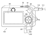
図1は、本発明の撮像装置の実施形態の一例であるデジタルカメラを背面側から見た斜視図である。 FIG. 1 is a perspective view of a digital camera, which is an example of an embodiment of an image pickup apparatus of the present invention, viewed from the back side.
図1に示すように、本実施形態のデジタルカメラ100(以下、カメラ100という)は、背面側に画像や各種情報を表示するLCD等の表示部28が設けられている。カメラ100の背面側の表示部28の側部には、モード切替スイッチ60、コントローラホイール73及び各種操作を受け付ける各種スイッチ、ボタン、タッチパネル等の操作部材より構成される操作部70が設けられている。カメラ100の正面側には、後述する撮影レンズ103やレンズバリア102(図2参照)等が設けられている。
As shown in FIG. 1, the digital camera 100 (hereinafter referred to as the camera 100) of the present embodiment is provided with a
カメラ100の上面部には、レリーズボタン61及び電源スイッチ72等が設けられ、カメラ100の側面部には、コネクタ112が設けられており、コネクタ112には、外部機器とカメラ100とを通信可能に接続するケーブル111が接続されている。カメラ100の底部には、メモリカード等の記録媒体200が着脱可能に装着されるスロット部201が設けられ、スロット部201は、蓋部202により開閉可能に覆われる。
A
図2は、図1に示すカメラ100の制御系を説明するブロック図である。図2において、撮影レンズ103は、ズームレンズ、フォーカスレンズを含むレンズ群により構成される。撮像素子22は、CCDセンサやCMOSセンサ等で構成され、撮影レンズ103を通過して結像した被写体像を光電変換して電気信号に変換する。また、撮像素子22は、A/D変換機能を備えている。
FIG. 2 is a block diagram illustrating a control system of the
焦点検出部23では、本実施形態では、像面位相差AF方式で焦点検出を行うため、画像処理部24で各種補正を行ったデジタル画像信号から得られる焦点検出情報などからデフォーカス量を算出してシステム制御部50に出力する。
In the present embodiment, since the
シャッタ101は、絞り機能を備え、非撮影時には閉じて撮像素子22を遮光し、撮影時には開いて撮像素子22へ被写体光束を導く。レンズバリア102は、撮影レンズ103を含む撮像系を覆うことにより、撮影レンズ103、シャッタ101、撮像素子22を含む撮像系の汚れや破損を防止する。
The
画像処理部24は、撮像素子22から出力されるデータ、又はメモリ制御部15からの画像データに対して所定の画素補間や縮小といったリサイズ処理や色変換処理を行う。また、画像処理部24では、撮像した画像データを用いて所定の演算処理が行われ、得られた演算結果に基づいてシステム制御部50が露光制御、測距制御を行う。これにより、TTL(スルー・ザ・レンズ)方式のAE(自動露出)処理、EF(フラッシュ自動調光発光)処理が行われる。
The
また、画像処理部24では、撮像素子22で撮像した画像信号を用いた像面位相差AF方式によるAF処理の他に、所定の演算処理を行い、得られた演算結果に基づいてTTL方式のAWB(オートホワイトバランス)処理も行っている。
In addition to the AF processing by the image plane phase difference AF method using the image signal picked up by the
撮像素子22の出力データは、画像処理部24及びメモリ制御部15を介して、或いはメモリ制御部15を介してメモリ32に直接書き込まれる。メモリ32は、撮像素子22によって取得およびA/D変換された画像データや、表示部28に表示するための画像データを格納する。メモリ32は、所定枚数の静止画像や所定時間の動画像および音声を格納するのに十分な記憶容量を備えている。また、メモリ32は画像表示用のメモリ(ビデオメモリ)を兼ねている。
The output data of the
D/A変換器13は、メモリ32に格納されている画像表示用のデータをアナログ信号に変換して表示部28に供給する。これにより、メモリ32に書き込まれた表示用の画像データがD/A変換器13を介して表示部28に表示される。表示部28は、D/A変換器13からのアナログ信号に応じた表示を行う。撮像素子22で一度A/D変換され、メモリ32に蓄積されたデジタル信号をD/A変換器13においてアナログ変換し、表示部28に逐次転送して表示することで、電子ビューファインダとして機能し、画角等を決定するためのスルー画像表示を行える。
The D/
不揮発性メモリ56は、電気的に消去・記録可能なメモリであり、例えばフラッシュメモリ等が用いられる。不揮発性メモリ56には、システム制御部50の動作用の定数、プログラム等が記憶される。システムメモリ52には、RAMが用いられる。システムメモリ52は、システム制御部50の動作用の定数、変数、不揮発性メモリ56から読み出したプログラム等を展開する。
The
システム制御部50は、デジタルカメラ100全体を制御する。システム制御部50は、例えば不揮発性メモリ56に記録されたプログラムをシステムメモリ52に展開して所定の処理を実行する。また、システム制御部50は、メモリ32、D/A変換器13、表示部28等を制御することにより表示制御も行う。システム制御部50はシステムタイマーを含み、当該システムタイマーは、各種制御に用いる時間や内蔵時計の時間を計測する計時部である。
The
モード切替スイッチ60は、システム制御部50の動作モードを静止画記録モード、動画記録モード、再生モード等のいずれかに切り替える。静止画記録モードに含まれるモードとしては、オート撮影モード、オートシーン判別モード、マニュアルモード、撮影シーン別の撮影設定となる各種シーンモード、プログラムAEモード、カスタムモード等がある。
The
モード切り替えスイッチ60により、静止画撮影モードに含まれるこれらのモードのいずれかに直接切り替えることができる。あるいは、モード切り替えスイッチ60で静止画撮影モードに一旦切り換えた後に、静止画撮影モードに含まれるこれらのモードのいずれかに、他の操作部材を用いて切り替えるようにしてもよい。同様に、動画撮影モードにも複数のモードが含まれていてもよい。
The
レリーズスイッチ(SW1)62は、レリーズボタン61の操作途中、例えば半押し操作によりオンする。レリーズスイッチ(SW1)62のオン信号により、システム制御部50は、AF(オートフォーカス)処理、AE(自動露出)処理、AWB(オートホワイトバランス)処理、EF(フラッシュ自動調光発光)処理等の撮影準備動作を開始する。
The release switch (SW1) 62 is turned on during the operation of the
レリーズスイッチ(SW2)64は、レリーズボタン61の操作完了、例えば全押し操作によりオンする。レリーズスイッチ(SW2)64のオン信号により、システム制御部50は、撮像素子22の信号読み出しから記録媒体200に画像データを書き込むまでの一連の撮影動作を開始する。
The release switch (SW2) 64 is turned on when the operation of the
操作部70は、表示部28に表示される種々の機能アイコンを選択操作する各種機能ボタンとしても用いられる。機能ボタンとしては、例えば終了ボタン、戻るボタン、画像送りボタン、ジャンプボタン、絞込みボタン、属性変更ボタン等がある。例えば、メニューボタンが押されると各種の設定可能なメニュー画面が表示部28に表示される。ユーザは、表示部28に表示されたメニュー画面と、上下左右の4方向ボタンやSETボタンとを用いて直感的に各種設定を行うことができる。
The
AF補助光源71は、低輝度時に発光させて、被写体を照明する。コントローラホイール73は、方向ボタンと共に選択項目を指示する際などに使用される。コントローラホイール73を回転操作すると、操作量に応じて電気的なパルス信号が発生し、このパルス信号に基づいて、システム制御部50は、カメラ100の各部を制御する。また、このパルス信号によって、システム制御部50は、コントローラホイール73が回転操作された角度や、何回転したかなどを判定することができる。
The AF auxiliary
なお、コントローラホイール73は、回転操作が検出できる操作部材であれば特に限定されない。例えば、ユーザの回転操作に応じてコントローラホイール73自体が回転してパルス信号を発生するダイヤル操作部材であってもよい。また、タッチセンサよりなる操作部材で、コントローラホイール73自体は回転せず、コントローラホイール73上でのユーザの指の回転動作などを検出するものであってもよい。
The
電源制御部80は、電池検出回路、DC−DCコンバータ、通電するブロックを切り替えるスイッチ回路等により構成され、電池の装着の有無、電池の種類、電池残量の検出を行う。また、電源制御部80は、その検出結果及びシステム制御部50の指示に基づいてDC−DCコンバータを制御し、必要な電圧を必要な期間、記録媒体200を含む各部へ供給する。電源部40は、アルカリ電池やリチウム電池等の一次電池やNiCd電池やNiMH電池、Li電池等の二次電池、ACアダプター等からなる。記録媒体I/F18は、メモリカード等の記録媒体200とのインターフェースである。
The power
図3は、撮像素子22の画素の配置を概略的に示す図である。図3に示すように、撮像素子22は、複数の瞳分割画素が行方向および列方向に二次元状に配置され、一つの瞳分割画素にFD(フォトダイオード)からなる複数の分割画素(光電変換部)A,Bを有する。システム制御部50は、画像処理部24を制御して分割画素A,Bからそれぞれ読み出したA信号301とB信号302を用いて焦点検出信号を生成し、生成した焦点検出信号に基づき像面位相差AFを行う。
FIG. 3 is a diagram schematically showing the arrangement of pixels of the
ここで、従来における信号の読み出す順序について説明する。まず、撮像素子22の瞳分割画素から一方のA信号301のみを読み出した後、撮像素子22内でA信号301とB信号302が加算されたA+B信号を読み出す。そして、A+B信号からA信号301を減算してB信号を得る。
Here, a conventional signal reading order will be described. First, only one A
図4は、図3で説明した従来の読み出し方式で撮像素子22の瞳分割画素から読み出したA信号,B信号,A+B信号を用いた画像の復元処理を説明するブロック図である。なお、以下の説明では、便宜上、A信号,B信号,A+B信号をそれぞれA画像,B画像,A+B画像として説明する。また、本処理はシステム制御部50の制御に基づいて画像処理部24にて実行される。
FIG. 4 is a block diagram illustrating an image restoration process using the A signal, B signal, and A+B signal read from the pupil division pixels of the
まず、撮像素子22の瞳分割画素からA画像を読み出した後、A画像とB画像が加算されたA+B画像を読み出す。次に、画像判別ブロックでは、読み出している画像がA画像かA+B画像かを判別して振り分ける。ここでは、先にA画像を読み出し、後に加算されたA+B画像を読み出すので、処理を同時化するため、待ち合わせ回路で処理タイミングを揃え、双方の画像が揃ったら、A+B画像からA画像を減算することで、B画像を得る。そして、A画像とB画像が分離されたら、それぞれで画像の補正処理を行って垂直加算処理を行い、処理後の画像を測距演算ブロックへ出力する。
First, the A image is read from the pupil division pixels of the
このとき、A+B画像からB画像を減算することで、S/Nが原理上3dB悪化してしまう。そこで、本実施形態では、次のようにして位相差情報のノイズ差が生じないようにしている。以下、説明する。 At this time, by subtracting the B image from the A+B image, the S/N deteriorates by 3 dB in principle. Therefore, in the present embodiment, the noise difference of the phase difference information is prevented as follows. This will be described below.
図5は、本実施形態において、撮像素子22の瞳分割画素からのA画像,B画像,A+B画像の読み出しタイミングを示すタイミングチャート図である。図5において、水平同期信号HDのタイミングで、まず、瞳分割画素から一方のA画像が読み出され、続いて加算されたA+B画像が読み出される。次の水平同期信号HDタイミングでは、読み出し順序が逆になり、瞳分割画素から他方のB画像が先に読み出され、続いてA+B画像が読み出される。
FIG. 5 is a timing chart showing the read timing of the A image, the B image, and the A+B image from the pupil division pixels of the
これを行単位で交互に繰り返して列方向に垂直加算することで、A画像とB画像のノイズレベルを揃えることができる。ここで、A画像は、本発明の第1画像信号の一例に相当し、B画像は、本発明の第2画像信号の一例に相当し、A+B画像は、本発明の第3画像信号の一例に相当する。 By repeating this alternately in units of rows and performing vertical addition in the column direction, the noise levels of the A image and the B image can be made uniform. Here, the A image corresponds to an example of the first image signal of the present invention, the B image corresponds to an example of the second image signal of the present invention, and the A+B image is an example of the third image signal of the present invention. Equivalent to.
図6は、図5で説明した本実施形態の読み出し方式で撮像素子22の瞳分割画素から読み出したA画像,B画像,A+B画像を用いた画像の復元処理を説明するブロック図である。図6の処理は、例えば不揮発性メモリ56に記録されたプログラムがシステムメモリ52に展開されてシステム制御部50が画像処理部24を制御することで実行される。
FIG. 6 is a block diagram illustrating an image restoration process using the A image, the B image, and the A+B image read from the pupil division pixels of the
本実施形態では、A画像とB画像の読み出し順序を行単位で交互に切り替えるため、画像の復元方法が毎ラインで異なる。このため、2つの垂直加算回路への入力を入れ替える必要がある。 In the present embodiment, the reading order of the A image and the B image is alternately switched on a row-by-row basis, and thus the image restoration method is different for each line. Therefore, it is necessary to switch the inputs to the two vertical addition circuits.
まず、画像判別ブロックでは、撮像素子22から読み出している画像がA画像かB画像かA+B画像かを判別して振り分ける。次に、図4と同様に、処理を同時化するため、待ち合わせ回路で処理タイミングを揃え、すべての画像が揃ったら、A+B画像からA画像及びB画像をそれぞれ減算することで、分離されたA画像及びB画像を生成する。ここで、分離されたA画像は、本発明の第1分離画像信号の一例に相当し、分離されたB画像は、本発明の第2分離画像信号の一例に相当する。
First, in the image discriminating block, it is discriminated whether the image read out from the
このとき、前述したように、A画像とB画像の読み出し順序を行単位で交互に切り替えている。このため、A画像を先に読み出す場合には、入れ替えブロックによる入れ替えは行われないが、B画像を先に読み出す場合には、入れ替えブロックで入力画像を入れ替えてそれぞれA垂直加算回路及びB垂直加算回路へ出力する。画像補正は、A画像とB画像とでは、出力特性が異なるので、補正パターンを切り替える必要がある。 At this time, as described above, the reading order of the A image and the B image is alternately switched row by row. Therefore, when the A image is read out first, the replacement block is not replaced. However, when the B image is read out first, the input images are replaced by the replacement block and the A vertical addition circuit and the B vertical addition are performed, respectively. Output to the circuit. In the image correction, since the output characteristics of the A image and the B image are different, it is necessary to switch the correction pattern.
1ライン単位でノイズレベルを見ると、それぞれノイズレベルは異なっているが、その後に垂直加算回路で異なるノイズレベルの画像同士を列方向に加算することで、測距演算回路によりA画像とB画像のノイズレベルを均一化した一対の焦点検出信号が生成される。そして、生成された一対の焦点検出信号は、焦点検出部23に出力される。
Looking at the noise level on a line-by-line basis, the noise levels are different, but after that, by adding images with different noise levels in the column direction in the vertical addition circuit, the A calculation image and the B image are calculated by the distance measurement calculation circuit. A pair of focus detection signals in which the noise levels of are uniformized are generated. Then, the pair of focus detection signals generated is output to the
図7は、画像処理部24で前述した各種補正を行った後に、画像処理部24から焦点検出部23へ出力される一対の焦点検出信号を示すグラフ図である。図7において、横軸は連結された信号の画素並び方向を示し、縦軸は信号の強度である。
FIG. 7 is a graph showing a pair of focus detection signals output from the
撮影レンズ103は、撮像素子22に対してデフォーカスした状態であるため、図7に示すように、焦点検出信号430aは左側にずれ、焦点検出信号430bは右側にずれた状態となっている。この焦点検出信号430a,430bのずれ量を焦点検出部23で周知の相関演算などによってデフォーカス量として算出することにより、撮影レンズ103がどれだけデフォーカスしているかを知ることができる。
Since the taking
そして、システム制御部50は、撮影レンズ103のレンズ位置情報と焦点検出部23から得られるデフォーカス量からフォーカスレンズの駆動量を算出する。その後、システム制御部50は、フォーカスレンズの位置情報から撮影レンズ103を駆動するべき位置情報を不図示のレンズ駆動回路に送信する。これにより、撮影レンズ103を光軸方向に駆動して合焦動作を行うことが可能となる。
Then, the
図8は、A画像とB画像の読み出し順序を行単位で交互に切り替える条件を示す図である。A画像とB画像の読み出し順序を行単位で交互に切り替えることにより、固定パターンノイズの出力が変化する可能性がある。このため、撮影時のISO感度や温度の高低により、A画像とB画像の読み出し順序の切り替え方式を変更する。 FIG. 8 is a diagram showing conditions for alternately switching the reading order of the A image and the B image row by row. By alternately switching the reading order of the A image and the B image row by row, the output of the fixed pattern noise may change. For this reason, the method of switching the reading order of the A image and the B image is changed depending on the ISO sensitivity and the temperature level at the time of shooting.
低ISO感度・低温環境では、ランダムノイズ量が少なく、固定パターンノイズの変化が表れやすいため、A画像とB画像の読み出し順序の切り替えは行わない方が良い。ISO感度が上げるにつれて、垂直加算回路での加算行数を減らしていき、高ISO感度時(例えばISO1600)には固定パターンノイズがランダムノイズに埋もれて目立ちにくくなるため、1行ごとの切り替えとする。また、温度によってもランダムノイズ量は変化するので、低温時は、A画像とB画像の読み出し順序の切り替えをなるべく少なくするようにして、高温時には、切り替えを積極的に多くするようにする。 In a low ISO sensitivity/low temperature environment, the amount of random noise is small and changes in fixed pattern noise are likely to occur. Therefore, it is better not to switch the reading order of the A image and the B image. As the ISO sensitivity increases, the number of rows added in the vertical addition circuit is reduced. At high ISO sensitivity (for example, ISO1600), fixed pattern noise is buried in random noise and becomes inconspicuous, so switching is performed for each row. .. Since the random noise amount also changes depending on the temperature, the switching of the reading order of the A image and the B image is reduced as much as possible at the low temperature, and the switching is actively increased at the high temperature.
図9は、撮像素子22からのA画像とB画像の読み出し順序と減算により得られたA画像とB画像のノイズ量を説明する図である。
FIG. 9 is a diagram for explaining the reading order of the A image and the B image from the
図9の例では、1行ごとに撮像素子22からのA画像とB画像の読み出し順序を交互に切り替えている。撮像素子22から読み出した後にA画像とB画像の分離を行うと、減算によって得られた画像はノイズが3dB悪化する。最初の行は、B画像のノイズが3dB悪く、次の行は、A画像のノイズが3dB悪い状態が繰り返される。
In the example of FIG. 9, the reading order of the A image and the B image from the
これを2行ごとに垂直加算回路で垂直加算平均し、さらに、複数行の垂直加算を行うことで、A画像とB画像のノイズレベルが揃い、不要な垂直加算を行う必要がなくなる。なお、垂直ライン加算行数は、ISO感度だけでなく、温度やシャッタ速度により最適な行数を加算すればよい。また、撮像素子22からのA画像とB画像の読み出し順序を交互に切り替えるタイミングは2行以上ごとであってもよい。垂直ライン加算行数の中で、単独でも読み出される階数が同数であれば、本実施形態の効果と同様の効果を得ることが可能となる。
By vertically averaging every two rows by a vertical addition circuit and further performing vertical addition on a plurality of rows, the noise levels of the A image and the B image are aligned, and it becomes unnecessary to perform unnecessary vertical addition. It should be noted that the number of vertical line addition lines may be an optimum number of lines depending on the temperature and the shutter speed as well as the ISO sensitivity. Further, the timing of alternately switching the reading order of the A image and the B image from the
以上説明したように、本実施形態では、像面位相差AFを行う際に、2つの位相差信号のノイズ量を揃えて、低輝度シーンでもAF性能を向上させることが可能となる。また、加算行数を抑えることができるので、AF枠を小さくすることが可能となり、より小さい被写体へもピント合わせを行うことができる。 As described above, in the present embodiment, when performing the image plane phase difference AF, the noise amounts of the two phase difference signals can be made uniform to improve the AF performance even in a low-luminance scene. In addition, since the number of rows to be added can be suppressed, the AF frame can be made small, and a smaller object can be focused.
なお、本発明は、上記実施形態に例示したものに限定されるものではなく、本発明の要旨を逸脱しない範囲において適宜変更可能である。 It should be noted that the present invention is not limited to the examples illustrated in the above embodiments, and can be appropriately changed without departing from the scope of the present invention.
また、本発明は、以下の処理を実行することによっても実現される。即ち、本発明は、上述の実施形態の1以上の機能を実現するプログラムをネットワーク又は記憶媒体を介してシステム又は装置に供給し、そのシステム又は装置のコンピュータにおける1つ以上のプロセッサーがプログラムを読出し実行する処理でも実現可能である。また、1以上の機能を実現する回路(例えば、ASIC)によっても実現可能である。 The present invention is also realized by executing the following processing. That is, the present invention provides a program that implements one or more functions of the above-described embodiments to a system or apparatus via a network or a storage medium, and one or more processors in a computer of the system or apparatus read the program. It can also be realized by executing processing. It can also be realized by a circuit (for example, ASIC) that realizes one or more functions.
22 撮像素子
23 焦点検出部
24 画像処理部
50 システム制御部
52 システムメモリ
56 不揮発性メモリ
100 デジタルカメラ
22
Claims (7)
前記瞳分割画素の一方の画素から第1画像信号を読み出し、他方の画素から第2画像信号を読み出し、前記撮像素子で前記第1画像信号と前記第2画像信号が加算された第3画像信号を読み出す読み出し手段と、
前記読み出し手段による前記第1画像信号と前記第2画像信号との読み出し順序を行単位で交互に切り替える切り替え手段と、
前記第3画像信号から前記第1画像信号および前記第2画像信号を減算して前記第3画像信号から分離した第2分離画像信号および第1分離画像信号をそれぞれ取得する減算手段と、
前記読み出し手段により読み出された前記第1画像信号と前記減算手段により分離された前記第1分離画像信号、および前記読み出し手段により読み出された前記第2画像信号と前記減算手段により分離された前記第2分離画像信号をそれぞれ列方向に加算する加算手段と、を備え、
前記加算手段は、前記読み出し手段による前記第1画像信号と前記第2画像信号との読み出し順序を切り替える行数に応じて、列方向に加算する行数を変更することを特徴とする撮像装置。 An image sensor having a plurality of pupil division pixels arranged two-dimensionally in the row direction and the column direction,
A third image signal in which the first image signal is read from one of the pupil division pixels, the second image signal is read from the other pixel, and the first image signal and the second image signal are added by the image sensor. Reading means for reading
Switching means for alternately switching the reading order of the first image signal and the second image signal by the reading means on a row-by-row basis;
Subtraction means for subtracting the first image signal and the second image signal from the third image signal to obtain a second separated image signal and a first separated image signal separated from the third image signal, respectively.
The first image signal read by the reading unit and the first separated image signal separated by the subtracting unit, and the second image signal read by the reading unit and separated by the subtracting unit Adding means for adding the second separated image signals in the column direction ,
The image pickup apparatus , wherein the adding means changes the number of rows to be added in the column direction according to the number of rows for switching the reading order of the first image signal and the second image signal by the reading means.
前記一対の焦点検出信号により算出されたデフォーカス量に基づいてフォーカスレンズを駆動して合焦動作を行う合焦手段と、を備えることを特徴とする請求項1に記載の撮像装置。 An arithmetic means for generating a pair of focus detection signals by arithmetic operation based on the image signals added by the adding means;
The imaging device according to claim 1, further comprising: a focusing unit that drives a focus lens based on a defocus amount calculated by the pair of focus detection signals to perform a focusing operation.
前記瞳分割画素の一方の画素から第1画像信号を読み出し、他方の画素から第2画像信号を読み出し、前記撮像素子で前記第1画像信号と前記第2画像信号が加算された第3画像信号を読み出す読み出しステップと、
前記読み出しステップでの前記第1画像信号と前記第2画像信号との読み出し順序を行単位で交互に切り替える切り替えステップと、
前記第3画像信号から前記第1画像信号および前記第2画像信号を減算して前記第3画像信号から分離した第2分離画像信号および第1分離画像信号をそれぞれ取得する減算ステップと、
前記読み出しステップで読み出された前記第1画像信号と前記減算ステップで分離された前記第1分離画像信号、および前記読み出しステップで読み出された前記第2画像信号と前記減算ステップで分離された前記第2分離画像信号をそれぞれ列方向に加算する加算ステップと、を備え、
前記加算ステップは、前記読み出しステップによる前記第1画像信号と前記第2画像信号との読み出し順序を切り替える行数に応じて、列方向に加算する行数を変更することを特徴とする撮像装置の制御方法。 A method for controlling an image pickup apparatus including an image pickup element having a plurality of pupil division pixels arranged two-dimensionally in a row direction and a column direction, comprising:
A third image signal in which the first image signal is read from one of the pupil division pixels, the second image signal is read from the other pixel, and the first image signal and the second image signal are added by the image sensor. A read step for reading
A switching step of alternately switching the readout order of the first image signal and the second image signal in the readout step on a row-by-row basis;
A subtraction step of subtracting the first image signal and the second image signal from the third image signal to obtain a second separated image signal and a first separated image signal separated from the third image signal, respectively.
The first image signal read in the reading step and the first separated image signal separated in the subtracting step, and the second image signal read in the reading step and separated in the subtracting step An addition step of adding each of the second separated image signals in the column direction ,
In the image pickup device , the adding step changes the number of rows to be added in the column direction according to the number of rows for switching the reading order of the first image signal and the second image signal in the reading step . Control method.
Priority Applications (3)
| Application Number | Priority Date | Filing Date | Title |
|---|---|---|---|
| JP2016149848A JP6739272B2 (en) | 2016-07-29 | 2016-07-29 | Imaging device, control method thereof, and program |
| US15/658,446 US10277800B2 (en) | 2016-07-29 | 2017-07-25 | Image pickup apparatus with focus detection technique, control method therefor, and storage medium |
| CN201710631807.9A CN107666571B (en) | 2016-07-29 | 2017-07-28 | Image pickup apparatus having focus detection technology, control method therefor, and storage medium |
Applications Claiming Priority (1)
| Application Number | Priority Date | Filing Date | Title |
|---|---|---|---|
| JP2016149848A JP6739272B2 (en) | 2016-07-29 | 2016-07-29 | Imaging device, control method thereof, and program |
Publications (2)
| Publication Number | Publication Date |
|---|---|
| JP2018019324A JP2018019324A (en) | 2018-02-01 |
| JP6739272B2 true JP6739272B2 (en) | 2020-08-12 |
Family
ID=61010752
Family Applications (1)
| Application Number | Title | Priority Date | Filing Date |
|---|---|---|---|
| JP2016149848A Active JP6739272B2 (en) | 2016-07-29 | 2016-07-29 | Imaging device, control method thereof, and program |
Country Status (3)
| Country | Link |
|---|---|
| US (1) | US10277800B2 (en) |
| JP (1) | JP6739272B2 (en) |
| CN (1) | CN107666571B (en) |
Family Cites Families (14)
| Publication number | Priority date | Publication date | Assignee | Title |
|---|---|---|---|---|
| US6819360B1 (en) * | 1999-04-01 | 2004-11-16 | Olympus Corporation | Image pickup element and apparatus for focusing |
| JP5028154B2 (en) | 2007-06-20 | 2012-09-19 | キヤノン株式会社 | Imaging apparatus and control method thereof |
| JP4881987B2 (en) * | 2009-10-06 | 2012-02-22 | キヤノン株式会社 | Solid-state imaging device and imaging device |
| JP5755111B2 (en) * | 2011-11-14 | 2015-07-29 | キヤノン株式会社 | Driving method of imaging apparatus |
| JP2013157883A (en) * | 2012-01-31 | 2013-08-15 | Sony Corp | Solid-state imaging device and camera system |
| WO2013183378A1 (en) * | 2012-06-07 | 2013-12-12 | 富士フイルム株式会社 | Imaging apparatus, image processing apparatus, and image processing method |
| JP2014106476A (en) * | 2012-11-29 | 2014-06-09 | Canon Inc | Focus detection device, imaging device, imaging system, focus detection method, program and storage medium |
| JP2014183206A (en) * | 2013-03-19 | 2014-09-29 | Sony Corp | Solid-state imaging device, driving method of solid-state imaging device, and electronic apparatus |
| JP6317548B2 (en) * | 2013-04-10 | 2018-04-25 | キヤノン株式会社 | Imaging apparatus and control method thereof |
| KR102121531B1 (en) * | 2013-12-10 | 2020-06-10 | 삼성전자주식회사 | Apparatus and Method for Controlling a Focus Detectable Image Sensor |
| JP6584059B2 (en) * | 2014-09-26 | 2019-10-02 | キヤノン株式会社 | Imaging apparatus, control method therefor, program, and storage medium |
| JP6602109B2 (en) * | 2015-08-28 | 2019-11-06 | キヤノン株式会社 | Control device, imaging device, control method, program, and storage medium |
| CN105657252B (en) * | 2015-12-25 | 2018-01-02 | 青岛海信移动通信技术股份有限公司 | Image processing method and mobile terminal in a kind of mobile terminal |
| JP6688165B2 (en) * | 2016-06-10 | 2020-04-28 | キヤノン株式会社 | Imaging device and imaging system |
-
2016
- 2016-07-29 JP JP2016149848A patent/JP6739272B2/en active Active
-
2017
- 2017-07-25 US US15/658,446 patent/US10277800B2/en not_active Expired - Fee Related
- 2017-07-28 CN CN201710631807.9A patent/CN107666571B/en not_active Expired - Fee Related
Also Published As
| Publication number | Publication date |
|---|---|
| CN107666571A (en) | 2018-02-06 |
| CN107666571B (en) | 2020-06-09 |
| US10277800B2 (en) | 2019-04-30 |
| US20180035040A1 (en) | 2018-02-01 |
| JP2018019324A (en) | 2018-02-01 |
Similar Documents
| Publication | Publication Date | Title |
|---|---|---|
| JP6584059B2 (en) | Imaging apparatus, control method therefor, program, and storage medium | |
| US10530986B2 (en) | Image capturing apparatus, image capturing method, and storage medium | |
| JP2013218297A (en) | Focus adjustment device and focus adjustment method | |
| CN109964479B (en) | Image pickup apparatus and control method thereof | |
| JP6761303B2 (en) | Imaging device and its control method | |
| JP6739272B2 (en) | Imaging device, control method thereof, and program | |
| US10536621B2 (en) | Image capturing apparatus, storage medium and controlling method for correcting a second image by correcting a pixel value of the second image corresponding to a detected defective pixel | |
| JP2017090579A (en) | Focus detection device and method, as well as imaging device | |
| JP7129864B2 (en) | Imaging device and its control method | |
| US20230199342A1 (en) | Imaging device and imaging method | |
| JP6971715B2 (en) | Image pickup device, control method of image pickup device, and program | |
| US11277555B2 (en) | Image pickup apparatus that performs focus bracketing, control method therefor, and storage medium | |
| JP5836673B2 (en) | IMAGING DEVICE, IMAGING DEVICE CONTROL METHOD, AND COMPUTER PROGRAM | |
| US10536632B2 (en) | Imaging apparatus, control method, and non-transitory storage medium | |
| JP2019015886A (en) | Imaging apparatus | |
| JP6858059B2 (en) | Imaging device and its control method, program, storage medium | |
| JP7071217B2 (en) | Imaging device and its control method | |
| JP2019047144A (en) | Imaging device, control method for imaging device, and program | |
| JP2022150647A (en) | Image processing device, image processing method, imaging apparatus, program, and recording medium | |
| JP2023108866A (en) | Image processing apparatus, imaging apparatus, image processing apparatus control method, and program | |
| JP2020102794A (en) | Image processing device | |
| JP2017022623A (en) | Imaging apparatus and control method therefor, program, and storage medium | |
| JP2017022662A (en) | Imaging device |
Legal Events
| Date | Code | Title | Description |
|---|---|---|---|
| A621 | Written request for application examination |
Free format text: JAPANESE INTERMEDIATE CODE: A621 Effective date: 20190725 |
|
| A977 | Report on retrieval |
Free format text: JAPANESE INTERMEDIATE CODE: A971007 Effective date: 20200204 |
|
| A131 | Notification of reasons for refusal |
Free format text: JAPANESE INTERMEDIATE CODE: A131 Effective date: 20200324 |
|
| A521 | Request for written amendment filed |
Free format text: JAPANESE INTERMEDIATE CODE: A523 Effective date: 20200521 |
|
| TRDD | Decision of grant or rejection written | ||
| A01 | Written decision to grant a patent or to grant a registration (utility model) |
Free format text: JAPANESE INTERMEDIATE CODE: A01 Effective date: 20200622 |
|
| A61 | First payment of annual fees (during grant procedure) |
Free format text: JAPANESE INTERMEDIATE CODE: A61 Effective date: 20200721 |
|
| R151 | Written notification of patent or utility model registration |
Ref document number: 6739272 Country of ref document: JP Free format text: JAPANESE INTERMEDIATE CODE: R151 |