JP6738342B2 - System and method for improving hearing - Google Patents
System and method for improving hearing Download PDFInfo
- Publication number
- JP6738342B2 JP6738342B2 JP2017542487A JP2017542487A JP6738342B2 JP 6738342 B2 JP6738342 B2 JP 6738342B2 JP 2017542487 A JP2017542487 A JP 2017542487A JP 2017542487 A JP2017542487 A JP 2017542487A JP 6738342 B2 JP6738342 B2 JP 6738342B2
- Authority
- JP
- Japan
- Prior art keywords
- user
- smartphone
- microphone
- microphones
- audio
- Prior art date
- Legal status (The legal status is an assumption and is not a legal conclusion. Google has not performed a legal analysis and makes no representation as to the accuracy of the status listed.)
- Expired - Fee Related
Links
- 238000000034 method Methods 0.000 title claims description 49
- 238000012545 processing Methods 0.000 claims description 30
- 210000000988 bone and bone Anatomy 0.000 claims description 16
- 230000005236 sound signal Effects 0.000 claims description 15
- 239000007943 implant Substances 0.000 claims description 10
- 230000000694 effects Effects 0.000 claims description 8
- 230000003287 optical effect Effects 0.000 claims description 8
- 230000003321 amplification Effects 0.000 claims description 7
- 238000003199 nucleic acid amplification method Methods 0.000 claims description 7
- 239000003826 tablet Substances 0.000 claims description 6
- 238000004458 analytical method Methods 0.000 claims description 5
- 238000001514 detection method Methods 0.000 claims description 5
- 206010011878 Deafness Diseases 0.000 claims description 4
- 230000007774 longterm Effects 0.000 claims description 4
- 230000009467 reduction Effects 0.000 claims description 4
- 230000003111 delayed effect Effects 0.000 claims description 3
- 238000012544 monitoring process Methods 0.000 claims description 3
- 238000003491 array Methods 0.000 claims description 2
- 230000004886 head movement Effects 0.000 claims description 2
- 230000010370 hearing loss Effects 0.000 claims description 2
- 231100000888 hearing loss Toxicity 0.000 claims description 2
- 208000016354 hearing loss disease Diseases 0.000 claims description 2
- 230000004424 eye movement Effects 0.000 claims 1
- 230000001629 suppression Effects 0.000 claims 1
- 238000004891 communication Methods 0.000 description 35
- 210000003128 head Anatomy 0.000 description 25
- 238000005259 measurement Methods 0.000 description 13
- 230000006870 function Effects 0.000 description 12
- 239000011521 glass Substances 0.000 description 12
- 239000006260 foam Substances 0.000 description 8
- 238000010586 diagram Methods 0.000 description 6
- 210000005069 ears Anatomy 0.000 description 5
- 230000002093 peripheral effect Effects 0.000 description 5
- 239000004033 plastic Substances 0.000 description 5
- 230000002745 absorbent Effects 0.000 description 4
- 239000002250 absorbent Substances 0.000 description 4
- 210000000845 cartilage Anatomy 0.000 description 4
- 238000000576 coating method Methods 0.000 description 4
- 230000002708 enhancing effect Effects 0.000 description 4
- XLYOFNOQVPJJNP-UHFFFAOYSA-N water Substances O XLYOFNOQVPJJNP-UHFFFAOYSA-N 0.000 description 4
- 230000009471 action Effects 0.000 description 3
- 238000001914 filtration Methods 0.000 description 3
- 230000006872 improvement Effects 0.000 description 3
- 230000033001 locomotion Effects 0.000 description 3
- 238000000465 moulding Methods 0.000 description 3
- 230000004044 response Effects 0.000 description 3
- 241001422033 Thestylus Species 0.000 description 2
- 230000003416 augmentation Effects 0.000 description 2
- 239000011248 coating agent Substances 0.000 description 2
- 238000013461 design Methods 0.000 description 2
- 239000000835 fiber Substances 0.000 description 2
- 210000001595 mastoid Anatomy 0.000 description 2
- 239000000463 material Substances 0.000 description 2
- 239000002184 metal Substances 0.000 description 2
- 229910052751 metal Inorganic materials 0.000 description 2
- 230000003278 mimic effect Effects 0.000 description 2
- 230000004048 modification Effects 0.000 description 2
- 238000012986 modification Methods 0.000 description 2
- 238000005457 optimization Methods 0.000 description 2
- 230000008569 process Effects 0.000 description 2
- 210000001747 pupil Anatomy 0.000 description 2
- 229930192334 Auxin Natural products 0.000 description 1
- 229910000831 Steel Inorganic materials 0.000 description 1
- 230000004913 activation Effects 0.000 description 1
- 230000004075 alteration Effects 0.000 description 1
- 230000003190 augmentative effect Effects 0.000 description 1
- 239000002363 auxin Substances 0.000 description 1
- 230000008901 benefit Effects 0.000 description 1
- 230000005540 biological transmission Effects 0.000 description 1
- 230000008859 change Effects 0.000 description 1
- 238000011109 contamination Methods 0.000 description 1
- 238000013016 damping Methods 0.000 description 1
- 230000001419 dependent effect Effects 0.000 description 1
- 230000001815 facial effect Effects 0.000 description 1
- SEOVTRFCIGRIMH-UHFFFAOYSA-N indole-3-acetic acid Chemical group C1=CC=C2C(CC(=O)O)=CNC2=C1 SEOVTRFCIGRIMH-UHFFFAOYSA-N 0.000 description 1
- 238000002156 mixing Methods 0.000 description 1
- 230000008447 perception Effects 0.000 description 1
- 230000005855 radiation Effects 0.000 description 1
- 238000010079 rubber tapping Methods 0.000 description 1
- 230000008054 signal transmission Effects 0.000 description 1
- 239000007787 solid Substances 0.000 description 1
- 238000001228 spectrum Methods 0.000 description 1
- 229910001220 stainless steel Inorganic materials 0.000 description 1
- 239000010935 stainless steel Substances 0.000 description 1
- 239000010959 steel Substances 0.000 description 1
- 210000002268 wool Anatomy 0.000 description 1
Images


Classifications
-
- H—ELECTRICITY
- H04—ELECTRIC COMMUNICATION TECHNIQUE
- H04R—LOUDSPEAKERS, MICROPHONES, GRAMOPHONE PICK-UPS OR LIKE ACOUSTIC ELECTROMECHANICAL TRANSDUCERS; DEAF-AID SETS; PUBLIC ADDRESS SYSTEMS
- H04R1/00—Details of transducers, loudspeakers or microphones
- H04R1/20—Arrangements for obtaining desired frequency or directional characteristics
- H04R1/32—Arrangements for obtaining desired frequency or directional characteristics for obtaining desired directional characteristic only
- H04R1/40—Arrangements for obtaining desired frequency or directional characteristics for obtaining desired directional characteristic only by combining a number of identical transducers
- H04R1/406—Arrangements for obtaining desired frequency or directional characteristics for obtaining desired directional characteristic only by combining a number of identical transducers microphones
-
- G—PHYSICS
- G06—COMPUTING; CALCULATING OR COUNTING
- G06V—IMAGE OR VIDEO RECOGNITION OR UNDERSTANDING
- G06V10/00—Arrangements for image or video recognition or understanding
- G06V10/10—Image acquisition
- G06V10/17—Image acquisition using hand-held instruments
-
- G—PHYSICS
- G06—COMPUTING; CALCULATING OR COUNTING
- G06V—IMAGE OR VIDEO RECOGNITION OR UNDERSTANDING
- G06V40/00—Recognition of biometric, human-related or animal-related patterns in image or video data
- G06V40/10—Human or animal bodies, e.g. vehicle occupants or pedestrians; Body parts, e.g. hands
- G06V40/16—Human faces, e.g. facial parts, sketches or expressions
- G06V40/161—Detection; Localisation; Normalisation
- G06V40/166—Detection; Localisation; Normalisation using acquisition arrangements
-
- G—PHYSICS
- G10—MUSICAL INSTRUMENTS; ACOUSTICS
- G10L—SPEECH ANALYSIS OR SYNTHESIS; SPEECH RECOGNITION; SPEECH OR VOICE PROCESSING; SPEECH OR AUDIO CODING OR DECODING
- G10L21/00—Processing of the speech or voice signal to produce another audible or non-audible signal, e.g. visual or tactile, in order to modify its quality or its intelligibility
- G10L21/02—Speech enhancement, e.g. noise reduction or echo cancellation
-
- H—ELECTRICITY
- H04—ELECTRIC COMMUNICATION TECHNIQUE
- H04R—LOUDSPEAKERS, MICROPHONES, GRAMOPHONE PICK-UPS OR LIKE ACOUSTIC ELECTROMECHANICAL TRANSDUCERS; DEAF-AID SETS; PUBLIC ADDRESS SYSTEMS
- H04R3/00—Circuits for transducers, loudspeakers or microphones
- H04R3/005—Circuits for transducers, loudspeakers or microphones for combining the signals of two or more microphones
-
- H—ELECTRICITY
- H04—ELECTRIC COMMUNICATION TECHNIQUE
- H04S—STEREOPHONIC SYSTEMS
- H04S7/00—Indicating arrangements; Control arrangements, e.g. balance control
- H04S7/30—Control circuits for electronic adaptation of the sound field
- H04S7/302—Electronic adaptation of stereophonic sound system to listener position or orientation
- H04S7/303—Tracking of listener position or orientation
-
- G—PHYSICS
- G10—MUSICAL INSTRUMENTS; ACOUSTICS
- G10L—SPEECH ANALYSIS OR SYNTHESIS; SPEECH RECOGNITION; SPEECH OR VOICE PROCESSING; SPEECH OR AUDIO CODING OR DECODING
- G10L21/00—Processing of the speech or voice signal to produce another audible or non-audible signal, e.g. visual or tactile, in order to modify its quality or its intelligibility
- G10L21/02—Speech enhancement, e.g. noise reduction or echo cancellation
- G10L21/0208—Noise filtering
- G10L21/0216—Noise filtering characterised by the method used for estimating noise
- G10L2021/02161—Number of inputs available containing the signal or the noise to be suppressed
- G10L2021/02166—Microphone arrays; Beamforming
-
- H—ELECTRICITY
- H04—ELECTRIC COMMUNICATION TECHNIQUE
- H04R—LOUDSPEAKERS, MICROPHONES, GRAMOPHONE PICK-UPS OR LIKE ACOUSTIC ELECTROMECHANICAL TRANSDUCERS; DEAF-AID SETS; PUBLIC ADDRESS SYSTEMS
- H04R2201/00—Details of transducers, loudspeakers or microphones covered by H04R1/00 but not provided for in any of its subgroups
- H04R2201/40—Details of arrangements for obtaining desired directional characteristic by combining a number of identical transducers covered by H04R1/40 but not provided for in any of its subgroups
- H04R2201/401—2D or 3D arrays of transducers
-
- H—ELECTRICITY
- H04—ELECTRIC COMMUNICATION TECHNIQUE
- H04R—LOUDSPEAKERS, MICROPHONES, GRAMOPHONE PICK-UPS OR LIKE ACOUSTIC ELECTROMECHANICAL TRANSDUCERS; DEAF-AID SETS; PUBLIC ADDRESS SYSTEMS
- H04R2225/00—Details of deaf aids covered by H04R25/00, not provided for in any of its subgroups
- H04R2225/43—Signal processing in hearing aids to enhance the speech intelligibility
-
- H—ELECTRICITY
- H04—ELECTRIC COMMUNICATION TECHNIQUE
- H04R—LOUDSPEAKERS, MICROPHONES, GRAMOPHONE PICK-UPS OR LIKE ACOUSTIC ELECTROMECHANICAL TRANSDUCERS; DEAF-AID SETS; PUBLIC ADDRESS SYSTEMS
- H04R2225/00—Details of deaf aids covered by H04R25/00, not provided for in any of its subgroups
- H04R2225/55—Communication between hearing aids and external devices via a network for data exchange
-
- H—ELECTRICITY
- H04—ELECTRIC COMMUNICATION TECHNIQUE
- H04R—LOUDSPEAKERS, MICROPHONES, GRAMOPHONE PICK-UPS OR LIKE ACOUSTIC ELECTROMECHANICAL TRANSDUCERS; DEAF-AID SETS; PUBLIC ADDRESS SYSTEMS
- H04R2225/00—Details of deaf aids covered by H04R25/00, not provided for in any of its subgroups
- H04R2225/61—Aspects relating to mechanical or electronic switches or control elements, e.g. functioning
-
- H—ELECTRICITY
- H04—ELECTRIC COMMUNICATION TECHNIQUE
- H04R—LOUDSPEAKERS, MICROPHONES, GRAMOPHONE PICK-UPS OR LIKE ACOUSTIC ELECTROMECHANICAL TRANSDUCERS; DEAF-AID SETS; PUBLIC ADDRESS SYSTEMS
- H04R2410/00—Microphones
- H04R2410/01—Noise reduction using microphones having different directional characteristics
-
- H—ELECTRICITY
- H04—ELECTRIC COMMUNICATION TECHNIQUE
- H04R—LOUDSPEAKERS, MICROPHONES, GRAMOPHONE PICK-UPS OR LIKE ACOUSTIC ELECTROMECHANICAL TRANSDUCERS; DEAF-AID SETS; PUBLIC ADDRESS SYSTEMS
- H04R2420/00—Details of connection covered by H04R, not provided for in its groups
- H04R2420/07—Applications of wireless loudspeakers or wireless microphones
-
- H—ELECTRICITY
- H04—ELECTRIC COMMUNICATION TECHNIQUE
- H04R—LOUDSPEAKERS, MICROPHONES, GRAMOPHONE PICK-UPS OR LIKE ACOUSTIC ELECTROMECHANICAL TRANSDUCERS; DEAF-AID SETS; PUBLIC ADDRESS SYSTEMS
- H04R2430/00—Signal processing covered by H04R, not provided for in its groups
- H04R2430/20—Processing of the output signals of the acoustic transducers of an array for obtaining a desired directivity characteristic
- H04R2430/23—Direction finding using a sum-delay beam-former
-
- H—ELECTRICITY
- H04—ELECTRIC COMMUNICATION TECHNIQUE
- H04R—LOUDSPEAKERS, MICROPHONES, GRAMOPHONE PICK-UPS OR LIKE ACOUSTIC ELECTROMECHANICAL TRANSDUCERS; DEAF-AID SETS; PUBLIC ADDRESS SYSTEMS
- H04R25/00—Deaf-aid sets, i.e. electro-acoustic or electro-mechanical hearing aids; Electric tinnitus maskers providing an auditory perception
- H04R25/40—Arrangements for obtaining a desired directivity characteristic
- H04R25/407—Circuits for combining signals of a plurality of transducers
-
- H—ELECTRICITY
- H04—ELECTRIC COMMUNICATION TECHNIQUE
- H04S—STEREOPHONIC SYSTEMS
- H04S2420/00—Techniques used stereophonic systems covered by H04S but not provided for in its groups
- H04S2420/01—Enhancing the perception of the sound image or of the spatial distribution using head related transfer functions [HRTF's] or equivalents thereof, e.g. interaural time difference [ITD] or interaural level difference [ILD]
Landscapes
- Engineering & Computer Science (AREA)
- Physics & Mathematics (AREA)
- Health & Medical Sciences (AREA)
- Acoustics & Sound (AREA)
- Signal Processing (AREA)
- Otolaryngology (AREA)
- Multimedia (AREA)
- General Health & Medical Sciences (AREA)
- Human Computer Interaction (AREA)
- Theoretical Computer Science (AREA)
- General Physics & Mathematics (AREA)
- Computational Linguistics (AREA)
- Audiology, Speech & Language Pathology (AREA)
- Quality & Reliability (AREA)
- Oral & Maxillofacial Surgery (AREA)
- Circuit For Audible Band Transducer (AREA)
- Computer Networks & Wireless Communication (AREA)
- Neurosurgery (AREA)
- Details Of Audible-Bandwidth Transducers (AREA)
Description
<関連出願の相互参照>
本願は、2015年2月13日出願の米国特許仮出願第62/116,231号の優先権を主張するものであり、参照によりその開示の全てを本明細書に援用する。
<Cross-reference of related applications>
This application claims priority to US Provisional Application No. 62/116,231, filed February 13, 2015, the entire disclosure of which is incorporated herein by reference.
<技術分野>
本発明は、概して、聴力のためのシステムおよび方法に関する。より具体的には、本発明は聴力を改善するためのシステムおよび方法である。
<Technical field>
The present invention relates generally to systems and methods for hearing. More specifically, the present invention is a system and method for improving hearing.
補聴器は、ある一定の環境において良好に機能するが、補聴器上のマイクロフォンの場所は、指向性マイクロフォンおよびノイズキャンセルを十分に利用するのに最適な位置にはない。さらに、補聴器は、電力および電池寿命を有効に利用しなければならず、したがって、リアルタイムでのノイズキャンセル増幅や他のオーディオエンハンスメントに活用するのに十分に最適化することができない。加えて、レストランなどのノイズの多い環境によって、硬質表面でのノイズの跳ね返りや方向の変化というさらなる課題が生じている。 Hearing aids work well in certain circumstances, but the location of the microphone on the hearing aid is not optimally located to take full advantage of directional microphones and noise cancellation. In addition, hearing aids must make good use of power and battery life, and thus cannot be fully optimized for use in real-time noise cancellation amplification and other audio enhancements. In addition, noisy environments such as restaurants create additional challenges of bounce and change direction of noise on hard surfaces.
本発明の目的は、聴力が損失した個人のために聴力を改善するためのシステムおよび方法を提供することである。 It is an object of the present invention to provide a system and method for improving hearing for individuals with hearing loss.
本発明の目的は、頭部位置および/または注視を判定することにより、対象とするオーディオ領域を増大させる、聴力を改善するためのシステムおよび方法を提供することである。 It is an object of the present invention to provide a system and method for improving hearing that increases the audio area of interest by determining head position and/or gaze.
本発明の目的は、場所認識の解析、頭部または注視の追跡、マイクロフォンの組合せの選択、角度および強度、音声増幅ならびにノイズキャンセルの機能を実行するための小型マイクロプロセッサを含む、聴力を改善するためのシステムおよび方法を提供することである。 It is an object of the present invention to improve hearing, including a small microprocessor for performing functions of location recognition analysis, head or gaze tracking, microphone combination selection, angle and intensity, voice amplification and noise cancellation. To provide a system and method therefor.
本発明の目的は、手に保持されるケースに上記機能が含まれる、聴力を改善するためのシステムおよび方法を提供することである。 It is an object of the present invention to provide a system and method for improving hearing that includes the above features in a hand-held case.
本発明の目的は、装置がテーブル上に置かれるか、あるいは、手に持った状態または机などの表面に起立させた状態で使用できるようにゴムで被覆した脚部を有するキックスタンドを有する、聴力を改善するためのシステムおよび方法を提供することである。 An object of the present invention is to have a kickstand having rubber-coated legs for use when the device is placed on a table or held in the hand or standing on a surface such as a desk, It is to provide a system and method for improving hearing.
本発明の目的は、聴力を改善するためのシステムおよび方法を提供することであり、当該システムは、左耳および/または右耳に向けられ得るパラメトリックスピーカで構成される。 It is an object of the present invention to provide a system and method for improving hearing, which system consists of parametric loudspeakers that can be directed to the left and/or right ear.
本発明の目的は、外部スピーカ、外部パラメトリックスピーカ、(小型イヤホンを有するかあるいは有しない)スマートフォンそれ自体、補聴器、補助聴覚装置、BLUETOOTH(登録商標)ヘッドセット、人工内耳、ヘッドホン、または聴取もしくは聴力向上のために用いられる他の任意の装置に対して音声パック(sound puck)がオーディオをストリーミングする、聴力を改善するためのシステムおよび方法を提供することである。 It is an object of the invention to provide an external speaker, an external parametric speaker, a smartphone itself (with or without small earphones), a hearing aid, an auxiliary hearing device, a BLUETOOTH® headset, a cochlear implant, headphones, or listening or hearing. It is to provide a system and method for improving hearing where a sound puck streams audio to any other device used for enhancement.
本発明の目的は、聴力を改善するためのシステムおよび方法を提供することであり、当該システムは、上記の音声向上に関する目的を達成するために、多数個のカメラを装備したスマートフォンと共に、またその注視追跡能力と統合して使用することができる。 It is an object of the present invention to provide a system and method for improving hearing, which system, together with a smartphone equipped with multiple cameras, achieves the above-mentioned object of audio enhancement. Can be used in combination with gaze tracking ability.
本発明の目的は、タブレット、時計または身体着用型装置である、聴力を改善するためのシステムおよび方法を提供することである。 It is an object of the present invention to provide a system and method for improving hearing, which is a tablet, watch or body-worn device.
本発明の目的は、マイクロフォンアレイからの注視追跡向上型音声増幅と同様の目的を達成する専用装置であるが、スマートフォンでもタブレットでもない専用装置を用いる、聴力を改善するためのシステムおよび方法を提供することである。 It is an object of the present invention to provide a system and method for improving hearing that is a dedicated device that achieves the same purpose as gaze tracking enhanced audio amplification from a microphone array, but using a dedicated device that is neither a smartphone nor a tablet. It is to be.
本発明の目的は、音声パックまたはIHOLDER(登録商標)装置以外の様々な電源によって駆動され得る、聴力を改善するためのシステムおよび方法を提供することである。 It is an object of the present invention to provide a system and method for improving hearing that can be driven by a variety of power sources other than voice packs or IHOLDER® devices.
本発明の目的は、オーディオが、遅延再生または繰り返し再生のために記録される、聴力を改善するためのシステムおよび方法を提供することである。 It is an object of the present invention to provide a system and method for improving hearing where audio is recorded for delayed or repeated playback.
本発明の目的は、音声をさらに向上させ通知を再生するためのパラメータが、装置自体で、スマートフォンまたはタブレットで、タッチ入力によって、またはユーザの特定の注視動作もしくは他のジェスチャーによって制御される、聴力を改善するためのシステムおよび方法を提供することである。たとえば、ボリュームを上げるためには素早く上を向き、ボリュームを下げるためには素早く下を向くことができる。通知を再生するには、スマートフォンを長時間注視するだけでもよいし、あるいは指または手を振る、指を鳴らすまたは頭を傾けるといった別のジェスチャーを行ってもよい。 It is an object of the present invention that the parameters for further enhancing the sound and playing the notification are controlled on the device itself, on the smartphone or tablet, by touch input or by the user's specific gaze action or other gesture. To provide a system and method for improving. For example, you can quickly turn upwards to increase the volume and quickly downwards to decrease the volume. To play the notification, one may simply look at the smartphone for a long time or make another gesture such as waving a finger or hand, ringing a finger or tilting the head.
本発明の目的は、聴力を改善するためのシステムおよび方法を提供することであり、ここで、音声をさらに向上させ通知を再生するためのパラメータは、EEGなどの身体の生命徴候をEEGセンサで検知するためのセンサを装備した小型イヤホン、プロセッサ、ならびにスマートフォンまたは通知再生の機能および起動を制御するための他のプロセッサ/装置へのその後の送信によって、制御される。たとえば、通知を再生するためには、スマートフォンでの通知の再生を起動する事前プログラムされたEEG信号を得るだけでよい。 It is an object of the present invention to provide a system and method for improving hearing, where the parameters for further enhancing the voice and playing the notification are the vital signs of the body, such as EEG, on the EEG sensor. Controlled by a small earphone equipped with a sensor for sensing, a processor, and subsequent transmission to a smartphone or other processor/device to control the functionality and activation of notification playback. For example, to play a notification, all that is required is to get a pre-programmed EEG signal that triggers the playing of the notification on the smartphone.
本発明の目的は、注視追跡が、目または頭部の位置だけで、または小型イヤホン内にある頭部位置センサによって行われかつ検出され、そして指向性を最適化するためにまたはビーム形成マイクロフォンアルゴリズムおよびノイズキャンセルを駆動するために使用される、聴力を改善するためのシステムおよび方法を提供することである。 It is an object of the invention that gaze tracking is performed and detected only at the position of the eye or head or by a head position sensor located in a mini earphone, and for optimizing the directivity or beamforming microphone algorithm. And to provide a system and method for improving hearing that is used to drive noise cancellation.
本発明の目的は、電力充電回路により、スマートフォンおよび小型イヤホンを充電するためにIHOLDER(登録商標)装置または音声パックも使用する、聴力を改善するためのシステムおよび方法を提供することである。 It is an object of the present invention to provide a system and method for improving hearing that also uses an IHOLDER® device or voice pack to charge smartphones and mini earphones with a power charging circuit.
本発明の目的は、発泡体を有するケースからマイクロフォンを分離すること、ケースに成形用プラスチックを充填すること、およびキャビティ内に吸収性発泡体層を挿入することを実現するケースまたはエンクロージャを提供することである。 It is an object of the present invention to provide a case or enclosure that provides for separating a microphone from a case having a foam, filling the case with molding plastic, and inserting an absorbent foam layer within the cavity. That is.
本発明は、上記補聴器が有する問題に多くの方法で対処するシステムおよび方法を提供する。まず、複数の指向性マイクロフォンまたはビーム形成マイクロフォンを有するマイクロフォンアレイは、エンクロージャに挿入され、より最適な位置に配置されてもよい。このような位置の例の一つは、レストランのテーブルに着いている聴覚障害者の目の前である。エンクロージャは、多くの形態をとることができ、指向性マイクロフォンまたはビーム形成マイクロフォンの小型または大型のアレイを収容することができる。マイクロフォンからのオーディオ入力を処理するために、エンクロージャは、補聴器で潜在的に可能なものよりも強力な処理回路を含むことができる。なぜなら、外部から電源を供給する、あるいは、より最適には、電池、プロセッサを有する携帯電話、または取り付けられたスマートフォンのスマートフォン電池(たとえば、スマートフォンの卓上ホルダ)によって電源を供給することができるからである。この装置は、BLUETOOTH(登録商標)プロトコル装置および他の無線通信プロトコルを含む、装置自体に含まれる電子部品を用いてもよく、あるいは、処理能力、電池、グラフィック処理ユニットすなわちGPU、カメラ、BLUETOOTH(登録商標)装置、ならびにジャイロスコープおよび位置検出用加速度計などの他のスマートフォン機能などの、スマートフォンに内蔵される機能のうちのいずれか1つまたは複数を利用してもよい。 The present invention provides systems and methods that address the problems of hearing aids described above in a number of ways. First, a microphone array with multiple directional or beam-forming microphones may be inserted into the enclosure and placed in a more optimal position. One example of such a position is in front of a deaf person sitting at a restaurant table. The enclosure can take many forms and can accommodate a small or large array of directional or beamforming microphones. To process audio input from the microphone, the enclosure can include more powerful processing circuitry than is potentially possible with a hearing aid. Because it can be powered externally or, more optimally, by a battery, a mobile phone with a processor, or a smartphone battery in an attached smartphone (eg, a smartphone desktop holder). is there. This device may use electronic components included in the device itself, including BLUETOOTH® protocol devices and other wireless communication protocols, or processing power, batteries, graphics processing units or GPUs, cameras, BLUETOOTH( Any one or more of the functions built into the smartphone may be utilized, such as registered trademark devices and other smartphone functions such as gyroscopes and accelerometers for position detection.
エンクロージャの上部でスマートフォンが利用され、このスマートフォンがユーザに向けて上向きに傾斜している(あるいはエンクロージャの一部であるミラーを介して上方に向けられている)場合、内蔵カメラ(またはエンクロージャに内蔵されたカメラ)自体を利用してユーザの頭部位置および注視を監視することができる。注視および頭部位置を把握することは、音声処理アルゴリズムの導出や、指向性マイクロフォンの選択、ビーム形成アルゴリズムおよび処理の最適化に役立ち得る。加えて、頭部位置を判定するセンサを含む小型イヤホンもまた、マイクロフォンの指向性を増大させたり、ビーム形成アルゴリズムを所望の対象とする人物/オーディオに対して導出することができる。サウンドパックは、補聴器、補助聴覚装置、ヘッドホン、小型イヤホン、人工内耳または骨伝導装置を含む、有線および/またはBLUETOOTH(登録商標)を装備した聴覚装置と接続することができる。一実施形態において、注視追跡は必要ではなく、頭部位置は、ジャイロスコープおよび/または加速度計を有する補聴器、ヘッドホン、小型イヤホン、または骨伝導装置を装備して頭部の動きを検出することによって判定され、これによって、どのマイクロフォンがアクティブリスニングに最適となるかを判定する能力が増大する。これは、マイクロフォンアレイの一部および/もしくはマイクロフォン組立体の一部であるセンサ、ならびに/またはスマートフォンに含まれるセンサとペアリングすることによって行うことができる。このペアリングは、頭部位置を判定するためにテーブルに置かれている特定のスマートフォンに対して行うことができる。別の実施形態において、振動といったジェスチャーを検出可能な回路を同様な聴取装置に装備し、それにより、ユーザは装置あるいは眼鏡のツルを指でタッピングすることによって、効果的に「クリック」を行うことができる。多数個のタップコードにより、異なるメッセージおよび/または動作を送信することができる。別の実施形態において、骨伝導「スピーカ」が、眼鏡のツルの後部に、耳の裏でかつ視野に入らないように取り付けられる。この実施形態において、骨伝導装置は、眼鏡の後方にスライドすることができるとともに、快適さを提供する発泡外装体を含むことができる。 Built-in camera (or built-in enclosure if a smartphone is utilized at the top of the enclosure and the smartphone is tilted upwards toward the user (or upwards through a mirror that is part of the enclosure) The camera itself can be used to monitor the user's head position and gaze. Knowing gaze and head position can help in deriving voice processing algorithms, optimizing directional microphone selection, beamforming algorithms and processing. In addition, small earphones that include a sensor for determining head position can also increase microphone directivity or derive beamforming algorithms for the desired target person/audio. The sound pack may be connected to wired and/or BLUETOOTH® equipped hearing devices, including hearing aids, auxiliary hearing devices, headphones, mini earphones, cochlear implants or bone conduction devices. In one embodiment, gaze tracking is not required, and the head position is determined by equipping a hearing aid with a gyroscope and/or accelerometer, headphones, small earphones, or a bone conduction device to detect head movement. Determined, which increases the ability to determine which microphone is best suited for active listening. This can be done by pairing with a sensor that is part of the microphone array and/or part of the microphone assembly, and/or a sensor included in the smartphone. This pairing can be done for a particular smartphone placed on the table to determine head position. In another embodiment, a similar listening device is equipped with circuitry capable of detecting gestures, such as vibration, so that the user can effectively "click" by tapping the device or the temples of the glasses with a finger. You can Multiple tap codes can send different messages and/or actions. In another embodiment, a bone conduction "speaker" is attached to the back of the temple of the eyeglass, behind the ear and out of sight. In this embodiment, the bone conduction device can include a foam exterior that can slide to the back of the glasses and provide comfort.
「音声パック」またはIHOLDER(登録商標)装置およびスマートフォンからの出力は、BLUETOOTH(登録商標)プロトコルまたは他の無線プロトコルを介して、無線を装備した補聴器、補助聴覚装置、BLUETOOTH(登録商標)プロトコルヘッドセット、小型イヤホン、ヘッドホン、骨伝導聴覚装置または人工内耳に送信することができる。対象とするオーディオ領域についての注視を判定するために、指向性マイクロフォンアレイを利用する能力と、頭部・注視追跡による増大とを組み合わせてもよい。対象とするオーディオ領域についての頭部位置を判定するために、頭部追跡および/もしくは注視追跡、ならびに/またはジャイロスコープ/加速度計を装備した増大構成(augmentation)と組み合わせた指向性マイクロフォンアレイおよび/またはビーム形成マイクロフォンアレイを使用することが可能である。皮膚または眼鏡のツルに取り付けられる、耳の隠れた骨用の骨伝導スピーカおよび/または軟骨伝導スピーカの裏側で、タップ振動検出を用いてマウスクリックまたはタッチ動作を模倣することができる。タッチ動作を模倣するために、特定の注視ジェスチャーを使用することが可能である。オーディオは、繰り返し再生または×秒の再生(たとえば、Tivo)のために記録してもよい。上記再生は、装置または眼鏡のツルでのタップまたはスマートフォンのカメラでの長時間にわたる注視といったジェスチャーの検出により開始することができる。加速度計およびジャイロスコープは動き追跡、睡眠追跡のために用いられてもよく、また、ECG、温度および皮膚水分(ただし、これらに限定されない)用のセンサを含み得る。小型の骨伝導スピーカ(「骨伝導装置」)を、耳の裏側で乳様突起(または耳の周囲の任意の骨の場所)に当てて、または耳の裏側で軟骨に当てて装着することができる。これらは、皮膚または耳の後部に密着する独立型であってもよく、あるいは他の音声パック装置とペアリングされた耳の裏側にある眼鏡のツルの後部に取り付けられ、かつ/または摺動させることができる。これらは、快適性をもたらすための発泡体を含んでいてもよく、眼鏡の各種様式とインターフェース接続するために汎用的なものとなる。これらの装置は、頭部位置を判定してマイクロフォン選択および音声最適化を増強するための1つまたは複数のセンサを含み得る。これらは、ジャイロスコープおよび/または加速度計の任意の組み合わせを含み得る。これらの装置は、活動、睡眠追跡等のFitbit式測定に使用することができ、かつ/または温度、皮膚水分および/またはECGを測定するための他のセンサを含むことができる。上記設計にマイクロプロジェクタを組み込むことが可能である。プロジェクタは、耳の裏にあってもよく、また、眼鏡のツルに沿って延びる光導波管に接続することができ、そして、所望の画像および/またはテキストをユーザの眼鏡の表面に、次いで瞳を通過させて目に投射する。これは、眼鏡にビームスプリッタのコーティングを設けるかあるいは設けることなく行うことができる。これにより、眼鏡を通して画像およびテキストを見ること、加えて、所望のシーンを見ることが可能となる。一実施形態において、この機構は視野から隠れている。ビームスプリッタは、特殊ガラスレンズ、コーティングおよび/または眼鏡用のプラスチックオーバーレイによって実現することができる。 Output from “Voice Pack” or IHOLDER® devices and smartphones via the BLUETOOTH® protocol or other wireless protocols, wirelessly equipped hearing aids, auxiliary hearing devices, BLUETOOTH® protocol heads. Can be sent to sets, mini earphones, headphones, bone conduction hearing devices or cochlear implants. The ability to utilize a directional microphone array to determine gaze for an audio region of interest may be combined with head-gaze tracking augmentation. Directional microphone array and/or head tracking and/or gaze tracking, and/or gyroscope/accelerometer-equipped augmentation for determining head position for an audio region of interest and/or Alternatively, a beam forming microphone array can be used. On the back side of bone and/or cartilage conduction speakers for hidden bones of the ear, which are attached to the vines of skin or glasses, tap vibration detection can be used to mimic mouse click or touch movements. It is possible to use specific gaze gestures to mimic touch movements. Audio may be recorded for repeat playback or x second playback (eg, Tivo). The playback can be initiated by the detection of a gesture such as a tap on the crane of the device or glasses or a long gaze at the camera of the smartphone. Accelerometers and gyroscopes may be used for motion tracking, sleep tracking, and may include sensors for (but not limited to) ECG, temperature and skin moisture. A small bone conduction speaker (“bone conduction device”) can be placed against the mastoid process (or any bone location around the ear) behind the ear or against cartilage behind the ear. it can. These may be stand-alone, close to the skin or the back of the ears, or attached and/or slid to the back of the temples of the spectacles behind the ears paired with other audio pack devices. be able to. These may include foam for comfort and are versatile for interfacing with various modalities of eyeglasses. These devices may include one or more sensors for determining head position to enhance microphone selection and voice optimization. These may include any combination of gyroscope and/or accelerometer. These devices can be used for Fitbit-based measurements such as activity, sleep tracking, and/or can include other sensors for measuring temperature, skin moisture and/or ECG. It is possible to incorporate a microprojector into the above design. The projector may be behind the ear and may be connected to an optical waveguide that extends along the temples of the spectacles, and the desired image and/or text may be placed on the surface of the user's spectacles and then the pupil. To pass through and project to the eye. This can be done with or without the beam splitter coating on the glasses. This allows viewing the images and text through the glasses as well as the desired scene. In one embodiment, this feature is hidden from view. The beamsplitter can be realized by special glass lenses, coatings and/or plastic overlays for spectacles.
本発明は、また、聴力を改善するためのシステムを提供し、当該システムは、プロセッサシステムと、通信インターフェースと、通信システムと、入力システムと、出力システムとを有するサーバシステムであって、通信ネットワークへのアクセスを有するサーバシステムと、オペレーティングシステムと、通信モジュールと、ウェブブラウザモジュールと、複数のマクロフォンから取得されたオーディオ信号を示す情報を処理してオーディオ信号の音質を向上させ、向上したオーディオ信号を送信するためのアプリケーションソフトウェアを記憶するための聴力改善用の非一時的記憶媒体とを有するメモリシステムと、聴力改善用の非一時的記憶媒体上に存在する聴力改善情報を表示するウェブサイトとを含み、出力システムおよび通信システムは、向上したオーディオ信号をユーザに送信する。 The present invention also provides a system for improving hearing, which system is a server system having a processor system, a communication interface, a communication system, an input system and an output system, the communication network A server system having access to an operating system, a communication module, a web browser module, and information indicating audio signals obtained from a plurality of macrophones to improve the sound quality of the audio signals and improve the audio quality. A memory system having a hearing-improving non-transitory storage medium for storing application software for transmitting signals, and a website for displaying hearing-improvement information present on the hearing-improving non-transitory storage medium. And the output system and the communication system send enhanced audio signals to the user.
本発明は、聴力を改善するための方法を提供し、当該方法は、複数のマイクロフォンからオーディオ信号を取得するステップと、オーディオ信号を表す情報を通信システム上で通信インターフェースを介してサーバに送信するステップと、送信された情報を処理してオーディオ信号の音質を向上させるステップと、向上したオーディオ信号をユーザに送信するステップとを含む。 The present invention provides a method for improving hearing, the method comprising obtaining audio signals from a plurality of microphones and transmitting information representative of the audio signals to a server via a communication interface on a communication system. The steps of: processing the transmitted information to improve the sound quality of the audio signal; and transmitting the enhanced audio signal to a user.
本発明を添付の図面に示す例示的かつ非限定的な実施形態によって説明する。図中、同様の参照符号は類似の要素を示す。 The present invention will be described by way of exemplary and non-limiting embodiments shown in the accompanying drawings. In the figures, like reference numbers indicate similar elements.
例示的な実施形態の様々な態様について、当業者がその研究を他の当業者に伝えるために一般的に用いる用語を用いて説明する。しかし、説明される側面の一部のみによって本発明が実施され得ることは、当業者には明らかであろう。説明のため、例示的な実施形態の理解を十分に図るべく、特定の数字、材料および構成について記載する。しかし、具体的な詳細事項が無くとも本発明が実施され得ることは、当業者には明らかであろう。また、例示的な実施形態を不明瞭にしないよう、周知の特徴については省略または簡略化している。 Various aspects of the exemplary embodiments are described using terms commonly used by those of ordinary skill in the art to convey the work to others skilled in the art. However, it will be apparent to one skilled in the art that the present invention may be practiced with only some of the described aspects. For purposes of explanation, specific numbers, materials and configurations are set forth in order to provide a thorough understanding of the exemplary embodiments. However, it will be apparent to one skilled in the art that the present invention may be practiced without the specific details. In addition, well-known features have been omitted or simplified in order not to obscure the exemplary embodiments.
各種動作は、本発明の理解に最も有用となるよう、順次、多数の個別の動作として説明する。しかし、説明の順序は、これらの動作が必ず順序に依存するということを示唆していると理解すべきではない。特に、これらの動作は、提示された順序で実施される必要はない。 The various operations are described as a number of individual operations in sequence, which is most useful in understanding the invention. However, the order of the description should not be understood as implying that these actions are necessarily order dependent. In particular, these acts need not be performed in the order presented.
「一実施形態において」という表現は、同じ実施形態について言及する場合もそうでない場合もある。「備える(comprising)」、「有する(having)」、「含む(including)」という用語は、文脈がそうでないことを示さない限り同義である。 The phrase "in one embodiment" may or may not refer to the same embodiment. The terms "comprising", "having", "including" are synonymous unless the context indicates otherwise.
図1A〜図1Eは、向上した変形スマートフォンの形態における本発明の実施形態を示す。図1Aは、スライド式の繰出し片12を含むように変形および向上したスマートフォン10の斜視図を示し、繰出し片12は、延出された際に露出する3つのマイクロフォン14A、14Bおよび14Cを有する。繰出し片12を後退させると、マイクロフォン14A、14Bおよび14Cは後退し、露出から保護される。スマートフォン10は、ユーザの光学画像を含む光学画像を取得するためのカメラ16を有する。このカメラは、スマートフォン上の他の位置に置くことが可能である。図1A〜図1Eの特定の実施形態において、上記マイクロフォンはビーム形成マイクロフォンであり、その動作については後述する。
1A-1E illustrate an embodiment of the present invention in the form of an enhanced modified smartphone. FIG. 1A shows a perspective view of a
図2は、スマートフォンがユーザに対してある位置にあるときに当該ユーザから取得された画像を、ユーザの目および他の頭部特徴を特定するために用いられるドットで示す基準点とともに示す。ユーザの頭部の光学画像からユーザの顔の特徴を特定するために用いられるアルゴリズムは、任意の既知のアルゴリズムであってよい。ここでは、参照座標系に対してヨー=−34.2°、ピッチ=11.0°およびロール=10.3°の値を有する、アルゴリズムから求めたヨー、ピッチおよびロールのパラメータを示す。ユーザの頭部の位置を特定するための他の方法としては、音声パックに含まれるウェブカムを使用すること、位置特定装置を小型イヤホンに埋め込みこと、位置特定装置を眼鏡に埋め込むこと等が挙げられる。勿論、ユーザの頭部を特定する他の方法が当業者によって想到されるであろう。本発明は本明細書に記載の方法に限定されるものではない。 FIG. 2 shows an image obtained from a user when the smartphone is in a position relative to the user, along with reference points represented by dots used to identify the user's eyes and other head features. The algorithm used to identify the facial features of the user from the optical image of the user's head may be any known algorithm. Shown here are the algorithmically determined yaw, pitch and roll parameters with values for yaw=−34.2°, pitch=11.0° and roll=10.3° with respect to the reference coordinate system. Other methods for determining the position of the user's head include using a webcam included in the audio pack, embedding the position determining device in small earphones, embedding the position determining device in eyeglasses, and the like. .. Of course, other methods of identifying the user's head will occur to those skilled in the art. The present invention is not limited to the methods described herein.
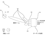
図3は、より詳細には後述するように、複数のビーム形成マイクロフォン(図3においては、このような4つのマイクロフォン)の音響ビームが、マイクロフォンの場所に対する会話中のユーザ334の位置に関する情報を用いたアルゴリズムに基づいてどのように規定されるかを平面図で示す。この場合、ビーム形成マイクロフォンのうちの1つは規定された音響ビーム領域332を有し、この音響ビーム領域332は、会話中のユーザの声を取得しかつ対象とするオーディオの取得を最適化するために、同図の左下に一例を示す背景ノイズと比較して、より大きく、また会話中のユーザの方に向けられている。装置310に含まれるオーディオ処理回路330は、音響ビーム形成器を形成する。
FIG. 3 shows that the acoustic beams of a plurality of beam forming microphones (four such microphones in FIG. 3) provide information regarding the position of the
対象とする音響信号の取得は、ビーム形成マイクロフォンまたは指向性マイクロフォンによって行うことが可能である。ビーム形成マイクロフォンの場合、ユーザの位置および向きに関するデータを用いてビーム形成マイクロフォンのビーム形成パターンを規定して、信号処理アルゴリズムによってユーザの聴力に提供される音響信号を向上させる。 Acquisition of the acoustic signal of interest can be done by a beamforming microphone or a directional microphone. In the case of a beamforming microphone, data regarding the position and orientation of the user is used to define the beamforming pattern of the beamforming microphone to enhance the acoustic signal provided to the user's hearing by the signal processing algorithm.
指向性マイクロフォンの場合、アレイとして設けられ得る複数の指向性マイクロフォンが備えられ、これらマイクロフォンのうちの1つまたは複数を所望の音響信号が提供されるように選択して、信号を向上させるとともに、ノイズや他の不要な音を最小限にする。指向性マイクロフォンを用いた実施形態の一例を図4に示す。同図は、合計6つの指向性マイクロフォン14A、14B、14C、14D、14E、14Fを有するスマートフォンを示し、1つの角につき1つのマイクロフォン(14A、14C、14Dおよび14F)およびスマートフォン10の1つの長辺につき1つのマイクロフォン(14B、14Eを参照)が配置される。ユーザの位置によっては、指向性マイクロフォンのうちの1つまたは複数を所望の音響信号の受信を最適化するよう有効化し、一方、ノイズの一因となる他のマイクロフォンを無効化する。所望の音響信号が図4の左下からのものである場合、指向性マイクロフォン14Bおよび14Cのいずれか一方または両方を有効化し、それ以外を無効化する。有効化したマイクロフォンの貢献度は、1つのマイクロフォンがその他のマイクロフォンよりも貢献度が高くなるように、標準的なミキシング技術を用いて調整することができる。
For directional microphones, a plurality of directional microphones may be provided that may be provided as an array, one or more of these microphones being selected to provide the desired acoustic signal to enhance the signal and Minimize noise and other unwanted sounds. An example of an embodiment using a directional microphone is shown in FIG. The figure shows a smartphone with a total of six
図3は、本発明の一実施形態に係るマイクロフォンアレイ300を示す。
FIG. 3 shows a
マイクロフォンアレイ300は、エンクロージャ310、複数の指向性マイクロフォンまたはビーム形成マイクロフォン(「マイクロフォン」)320および電子処理回路330を含み得る。エンクロージャ310は、プラスチック、金属または他の適した材料で形成されてもよい。マイクロフォン320は、ユーザの音声品質等を向上させ得るマイクロフォンアレイ320Aを含み得る。電子処理回路330は、エンクロージャ310内に含まれてもよい。電子処理回路330は、ユーザが着用する補聴器334からのいかなるオーディオ入力よりも聴こえやすいものであり得る複数の向上した音響ビーム332を生成し得る。
マイクロフォンアレイ300は、装置自体に含まれる、BLUETOOTH(登録商標)プロトコルおよび他の適した無線通信プロトコルを利用する電子処理回路330を使用するか、あるいは、処理能力、電力、電池、グラフィック処理ユニットすなわちGPU、カメラ、BLUETOOTH(登録商標)通信プロトコルおよび他のスマートフォン機能といったスマートフォン(図7、124)に内蔵された機能のうちの任意の1つまたは複数を利用することもできる。
The
マイクロフォンアレイは、エンクロージャに挿入され、より最適な位置に配置され得る複数のマイクロフォンを有してもよい。そのような例の一つとしては、レストランのテーブルに着いている聴覚障害者の目の前である。エンクロージャは、多くの形態をとることができ、小型または大型の指向性マイクロフォンアレイを収容することができる。マイクロフォンからのオーディオ入力を処理するために、エンクロージャは、補聴器で潜在的に可能なものよりも強力な処理回路を含むことができる。なぜなら、外部から電源を供給する、あるいは、より最適には、電池、プロセッサを有する携帯電話または取り付けられたスマートフォンのスマートフォン電池(たとえば、スマートフォンの卓上ホルダ)によって電源を供給することができるからである。この装置は、BLUETOOTH(登録商標)プロトコルおよび他の無線通信プロトコルを含む、装置自体に含まれる電子部品を用いてもよく、あるいは、処理能力、電源、電池、グラフィック処理ユニットすなわちGPU、カメラ、BLUETOOTH(登録商標)プロトコル、および他のスマートフォン機能といった、スマートフォンに内蔵される機能のうちのいずれか1つまたは複数を利用してもよい。 The microphone array may have multiple microphones that may be inserted into the enclosure and placed in a more optimal position. One such example is in front of a deaf person sitting at a restaurant table. The enclosure can take many forms and can accommodate a small or large directional microphone array. To process audio input from the microphone, the enclosure can include more powerful processing circuitry than is potentially possible with a hearing aid. This is because it can be powered externally, or more optimally by a battery, a cell phone with a processor or a smartphone battery of an attached smartphone (eg a smartphone desktop holder). .. This device may use electronic components contained within the device itself, including the BLUETOOTH® protocol and other wireless communication protocols, or processing power, power supplies, batteries, graphics processing units or GPUs, cameras, BLUETOOTH Any one or more of the functions built into the smartphone may be utilized, such as the (registered trademark) protocol and other smartphone functions.
エンクロージャの上部でスマートフォンが利用され、このスマートフォンがユーザに向けて上向きに傾斜している場合、内蔵カメラ(またはエンクロージャに内蔵されたカメラ)自体を利用してユーザの頭部位置および注視を監視することができる。注視および頭部位置を把握することは、上記アルゴリズムの導出や、指向性マイクロフォンの選択および処理の最適化に役立ち得る。 If a smartphone is used at the top of the enclosure and the smartphone is tilted upwards towards the user, the built-in camera (or the camera built into the enclosure) itself is used to monitor the user's head position and gaze be able to. Knowing gaze and head position can help in deriving the above algorithms and optimizing directional microphone selection and processing.
図5は、本発明の一実施形態に係る音声パック400を示す。
FIG. 5 shows an
音声パック400は、ケーシング410、入力ソケット420、出力ソケット430および1つまたは複数のスピーカ440を含み得る。
The
ケーシング410は、上面410Aおよび周壁板410Bを含み得る。ケーシング410は、プラスチック、金属、鋼、ステンレス鋼等で形成されてもよい。入力ソケット420は、ケーシング410の周壁板410B上に配置されてもよい。図5は、AUXIN入力ソケット420Aである入力ソケット420、AUXOUT表示灯422Aである第1の表示灯422、および透明電池表示426であり得る第2の表示灯424を示す。透明電池表示426は、音声パック400の電池(図示せず)の充電中に該電池が充電されているときに点滅によって通知するための機能表示として機能し得る。透明電池表示426は、音声パック400の前記電池が充電を維持している間は、前記電池が満充電であるときに点灯し続けることによって通知を行う機能表示として機能し得る。出力ソケット430は、直流および状態ベクトルソケット、すなわちDC/SV出力ソケット432等であってもよい。1つまたは複数のスピーカ440は、ケーシング410の上面410Aに配置されてもよい。1つまたは複数のスピーカ440は、1つまたは複数のパラメトリックスピーカ440A等であってもよい。
The
システムは、IHOLDER(登録商標)装置および/または音声パックを含み得る。システムは、正常な聴取環境において聴力を増強するためにも使用され得る。これは、補聴器、補助聴覚装置、BLUETOOTH(登録商標)プロトコルヘッドセット、小型イヤホン、ヘッドホンまたは人工内耳といった補助聴覚装置への無線接続(BLUETOOTH(登録商標)プロトコルおよびその他)によって実現され得る。また、補聴器のような耳装着型装置を使用することなく音声をユーザの左右の耳に直接向けるためのパラメトリックスピーカをシステム(指向性増大型注視追跡を含む)に装備することができる。 The system may include an IHOLDER® device and/or audio pack. The system can also be used to enhance hearing in a normal listening environment. This may be accomplished by a wireless connection (BLUETOOTH® protocol and others) to an auxiliary hearing device such as a hearing aid, a hearing aid, a BLUETOOTH® protocol headset, mini earphones, headphones or a cochlear implant. Also, the system (including augmented directional gaze tracking) can be equipped with parametric speakers to direct sound directly to the left and right ears of the user without the use of ear-mounted devices such as hearing aids.
スマートフォンホルダ(この1つのバージョンはIPHONE6(登録商標)装置用のもの、すなわち、IHOLDER(登録商標)装置)は、スマートフォンを、机に座りながら見るのに理想的な角度で机の上で保持する。このホルダの底部は、摺動を防止するためのゴムパッドを有する。IHOLDER(登録商標)装置は、IPHONE(登録商標)装置に対して電力および快適な視認をもたらすことができる。IHOLDER(登録商標)装置は、ユーザの顔を見ることができるように焦点および倍率を理想化した1つまたは複数のカメラを含み、また、2つ以上のカメラを利用して頭部位置および注視を判定してもよい。このIHOLDER(登録商標)カメラは、ユーザを常時監視しており、第1の注視認識ステップを(またはスマートフォンのソフトウェアを介して)行う回路を含む。注視認識の際、IPHONE(登録商標)装置は、ソフトウェアおよび/またはハードウェアのいずれかを介して、マイクロフォンアレイからの理想的なマイクロフォン組み合わせを選択する情報をフィードバックするとともに、ノイズキャンセルも行ってもよい。この機能は、Android、Windowsおよび他のスマートフォン、または同様に機能するがスマートフォンではない専用装置上でも実現され得る。 A smartphone holder (one version of which is for the IPHONE6® device, ie the IHOLDER® device) holds the smartphone on the desk at an ideal angle for sitting and looking at the desk. .. The bottom of this holder has a rubber pad for preventing sliding. The IHOLDER® device can provide power and comfortable viewing to the IPHONE® device. The IHOLDER® device includes one or more cameras with idealized focus and magnification so that the user's face can be seen, and two or more cameras are utilized to determine head position and gaze May be determined. The IHOLDER® camera constantly monitors the user and includes circuitry to perform the first gaze recognition step (or via software on the smartphone). During gaze recognition, the IPHONE® device provides feedback, either via software and/or hardware, with information to select the ideal microphone combination from the microphone array, as well as noise cancellation. Good. This feature may also be implemented on Android, Windows and other smartphones, or dedicated devices that function similarly but are not smartphones.
図7は、本発明の一実施形態に係るスマートフォンホルダ500を示す。より具体的には、図7は、表面に配置されたスマートフォンホルダ500を示す。
FIG. 7 shows a
スマートフォンホルダ500は、ベース510およびスマートフォン取付片520を含み得る。
The
ベース510は、底面510Aと、中間部510B’を有する上面510Bとを含み得る。ベース510は、ベース510の上面510Bの中間部510B’を有する上面510Bに配置された隆起中心継手512を含み得る。ベース510の上面510Bは、隆起中心継手512の周囲に配置された4つの等間隔配置の凹部514を含み得る。ベース510は、スマートフォンホルダ500が表面または物体等に配置されている間に動かないようにするために、ベース510の底面510Aに配置され得る1つまたは複数のゴムパッド516も含み得る。スマートフォン取付片520は、中心取付孔522を含んでいてもよく、中心取付孔522は4つの等間隔配置の取付タブ524をその周囲に有する。スマートフォン取付片520は、4つの等間隔配置の取付タブ524を有する中心取付孔522を、位置合わせした隆起中心継手512および4つの等間隔配置の凹部514に挿入し、スマートフォン取付片520に連結されたスマートフォン124を捩じることによりベース510に連結されてもよく、これにより、連結されたスマートフォン124が定位置に固定される。スマートフォン124は、1つまたは複数のカメラ530と、ユーザのビデオおよび音声をスマートフォン124のオーディオ能力の範囲で取得し得る音声記録アプリ540とを含み得る。
The base 510 may include a
図11Aは、本発明の一実施形態に係る聴力を改善するための方法のフローチャートを示す。 FIG. 11A shows a flowchart of a method for improving hearing according to one embodiment of the present invention.
方法600は、スマートフォンを、スマートフォンを持つユーザを見ることができる表面で保持するステップ610と、クライアントシステムに、スマートフォンを表面に固定しながら電力を供給させるステップ620と、ユーザを見ることができるように焦点および倍率を理想化したスマートフォンによってユーザを常時監視するステップ630と、スマートフォンのマイクロフォンアレイからの理想的なマイクロフォン組み合わせを選択するクライアントシステムからの聴覚情報をフィードバックするステップ640とを含み得る。
The
保持ステップ610における表面は、物体等の表面を含み得る。電力供給ステップ620におけるクライアントシステムは、マイクロフォンアレイ、音声パックまたはスマートフォンホルダを含み得る。常時監視ステップ630は、ユーザの頭部位置および注視を判定するために利用される2つ以上のカメラを使用してもよい。聴覚情報フィードバックステップ640は、1つもしくは複数の外部スピーカ、1つもしくは複数の外部パラメトリックスピーカ、1つもしくは複数の小型イヤホンを有するかあるいは有しないスマートフォン、補聴器、補助聴覚装置、BLUETOOTH(登録商標)プロトコルヘッドセット、人工内耳、一組のヘッドホン、または聴取もしくは聴力の改善に用いられる任意の装置からなる群から選択される装置からの聴覚情報を使用してもよい。聴覚情報フィードバックステップ640は、注視追跡、ノイズキャンセル、注視追跡解析、マイクロフォン組合せ選択および音声増幅を実行する1つまたは複数のステップも含み得る。命令が記憶された非一時的コンピュータ記憶媒体は、実行された際に、方法600全体のステップを実行し得る。
The surface in the holding
図11Bは、どのように音響信号が入力され、処理され、イヤホンに出力されるかを示すフロー信号図を示す。この場合のマイクロフォンアレイは、3つのマイクロフォンがBBF(ビーム形成器)に供給される。BBFは、ユーザの位置および向きを示す顔追跡器の信号もSMARTを介して受信してもよく、SMARTは、データ信号θ°およびβを出力する。SMARTは、テーブル・車・ポケットブロックに対しても出力を行い、このブロックは、ケースパラメータブロックに対して出力を行う。CRC−アルゴリズムは、音響処理を行う。 FIG. 11B shows a flow signal diagram showing how acoustic signals are input, processed and output to the earphones. In the microphone array in this case, three microphones are supplied to the BBF (beamformer). The BBF may also receive a face tracker signal indicating the position and orientation of the user via SMART, which outputs data signals θ° and β. SMART also outputs to table/car/pocket blocks, and this block outputs to case parameter blocks. The CRC-algorithm performs acoustic processing.
聴力を改善するためのシステムおよび方法が使用されるであろう環境の一つは、当該システムおよび方法によって聴力が改善され得るノイズの多い環境(すなわち、レストラン等)であってもよい。 One of the environments in which the systems and methods for improving hearing may be used may be a noisy environment (ie, a restaurant, etc.) in which the systems and methods may improve hearing.
センサおよび/またはマイクロフォンアレイが眼鏡に埋め込まれてもよい。ユーザの眼鏡の前部に小型マイクロフォンを取り付けて、眼鏡に含まれるビーム形成マイクロフォンおよび/または指向性マイクロフォンを用いて、ノイズ中での聴取能力を増強することが可能である。指向性チップおよび/または指向性マイクロフォンが眼鏡に埋め込まれてもよい。別の実施形態において、頭部の位置および追跡は、ジャイロスコープ/加速度計を装備した、小型イヤホン、ヘッドホン、骨伝導装置/軟骨伝導装置、補聴器、人工内耳、または、マイクロフォン選択、最適なオーディオ設定およびノイズキャンセルを最適化するために検出され用いられる他の任意の聴取装置を介して行ってもよい。別の実施形態において、オーディオ出力信号は、スピーカフォンを介して出力することが可能である。システムは、場所を検出しかつ当該場所の最適なオーディオ特性を制御するGPS装置などの、位置検出センサを含み得る。超小型骨伝導スピーカ(「骨伝導装置」)を耳の裏側で乳様突起(または耳の周囲の任意の骨の場所)に当てて、または耳の裏側で軟骨に当てて装着することができる。これらは、皮膚または耳の後部に密着する独立型であってもよく、あるいは他の音声パック装置とペアリングされた耳の裏側にある眼鏡のツルの後部に取り付けられ、かつ/または摺動させることができる。これらは、快適性をもたらすための発泡体を含んでいてもよく、眼鏡の各種様式とインターフェース接続するために汎用的なものであり得る。これらの装置は、頭部位置を判定してマイクロフォン選択および音声最適化を増強するための1つまたは複数のセンサを含み得る。センサは、ジャイロスコープおよび/または加速度計の任意の組み合わせを含み得る。これらの装置は、活動、睡眠追跡等のFitbit式測定に使用することもでき、かつ/または、温度、皮膚水分および/またはECGを測定するための他のセンサを含むことができる。 Sensors and/or microphone arrays may be embedded in the glasses. It is possible to attach a small microphone to the front of the user's spectacles and use the beam-forming and/or directional microphones included in the spectacles to enhance their ability to hear in noise. Directional chips and/or directional microphones may be embedded in the glasses. In another embodiment, head position and tracking is performed by gyroscope/accelerometer-equipped mini earphones, headphones, bone/cartilage conduction devices, hearing aids, cochlear implants, or microphone selection, optimal audio settings. And through any other listening device that is detected and used to optimize noise cancellation. In another embodiment, the audio output signal can be output via a speakerphone. The system may include location sensors, such as GPS devices that detect a location and control optimal audio characteristics of the location. A miniature bone conduction speaker (“bone conduction device”) can be placed against the mastoid (or any bone location around the ear) behind the ear or against cartilage behind the ear .. These may be stand-alone, close to the skin or the back of the ears, or attached and/or slid to the back of the temples of the spectacles behind the ears paired with other audio pack devices. be able to. These may include foam for comfort and may be universal for interfacing with various modalities of eyeglasses. These devices may include one or more sensors for determining head position to enhance microphone selection and voice optimization. The sensor may include any combination of gyroscope and/or accelerometer. These devices can also be used for Fitbit-based measurements such as activity, sleep tracking, and/or can include other sensors for measuring temperature, skin moisture and/or ECG.
以下の特許および公開特許出願が参照により本明細書に援用され、これらは、信号処理アルゴリズムによってローカル装置上で、あるいは遠隔サーバによって行うことが可能なタイプの信号向上に関する開示を提供する。 The following patents and published patent applications are hereby incorporated by reference, which provide disclosure regarding the types of signal enhancements that can be performed by a signal processing algorithm on a local device or by a remote server.
米国特許第8,953,817号は、指向性出力信号を生成するためのシステムおよび方法を開示する。その2つのマイクロフォンを本発明において使用することができ、音声を処理し向上させるためのアルゴリズムを本発明のシステムにおいて使用することができる。 US Pat. No. 8,953,817 discloses a system and method for generating a directional output signal. The two microphones can be used in the present invention and algorithms for processing and enhancing speech can be used in the system of the present invention.
米国特許第8,947,978号は、音声が到着する方向を推定するシステムおよび方法を開示する。そのマイクロフォンを本発明において使用することができ、音声を処理し向上させるためのアルゴリズムは、本発明のシステムにおいて使用することができ、または音声の発生源の場所を検出することができる。 US Pat. No. 8,947,978 discloses a system and method for estimating the direction of arrival of speech. The microphone can be used in the present invention, algorithms for processing and enhancing speech can be used in the system of the present invention, or the location of the source of speech can be detected.
米国特許第8,755,547号は、音声の了解度を向上させるための方法およびシステムを開示する。このシステムは、音声信号の音質を向上させるために本発明のシステムで使用することができる。 US Pat. No. 8,755,547 discloses a method and system for improving speech intelligibility. This system can be used in the system of the present invention to improve the sound quality of an audio signal.
米国公開特許出願第2013/0223644号は、マイクロフォン構成から受信された信号に含まれる不要な音声を低減するためのシステムおよび方法を記載する。このシステムは、音声信号の音質を向上させるために本発明のシステムにおいて使用することができる。 US Published Patent Application No. 2013/0223644 describes a system and method for reducing unwanted speech contained in a signal received from a microphone arrangement. This system can be used in the system of the present invention to improve the sound quality of an audio signal.
米国公開特許出願第2016/0005417号は、ノイズ低減システムおよび方法を開示する。このシステムは、ノイズを低減し、それによって音声信号の音質を向上させるために、本発明のシステムにおいて使用することができる。 US Published Patent Application No. 2016/0005417 discloses a noise reduction system and method. This system can be used in the system of the present invention to reduce noise and thereby improve the quality of the audio signal.
米国公開特許出願第2008/0063228は、音響的に透明なオクルージョンを低減するシステムおよび方法を開示する。このシステムは、音質または少なくともユーザによる音質の知覚を改善するために本発明のシステムにおいて使用されてもよい。 US Published Patent Application No. 2008/0063228 discloses systems and methods for reducing acoustically transparent occlusion. This system may be used in the system of the invention to improve the sound quality or at least the perception of the sound quality by the user.
上記の特許および公開特許出願は、音質を向上させるための、マイクロフォンなどの音響部品およびアルゴリズムの両方を開示する。これらのアルゴリズムは、当業者によって理解されるように、本発明のシステムにおけるアルゴリズムとして使用されてもよい。 The above patents and published patent applications disclose both acoustic components and algorithms, such as microphones, for improving sound quality. These algorithms may be used as algorithms in the system of the present invention, as will be appreciated by those skilled in the art.
図12Aは、外表面に取り付けられたマイクロフォンを有するエンクロージャの一実施形態を示す。本実施形態は、ケースの一端にプリズム状成形ゴム片を有しケースの他端に6つの(6)マイクロフォン(番号1〜6を参照)を有する堅牢なiPhone6+ケースの形態であるエンクロージャで構成される。成形ゴム「プリズム」を用いずに測定を行い、その性能に対する影響を調べた。さらなるマイクロフォンの場所(番号6を参照)は、装置の縁部付近に配置した。
FIG. 12A illustrates one embodiment of an enclosure having a microphone mounted on the outer surface. This embodiment comprises an enclosure in the form of a
図12Bは、堅牢なiPhone6+ケースおよび最適に配置された表面実装マイクロフォンを用いて構成された実施形態を示す。
FIG. 12B shows an embodiment configured with a
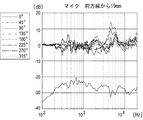
図13および図14は、図12Aのマイクロフォン#1からマイクロフォンを装置の後部(180°方位角)に向けて配置した状態で得られた測定値を示す。図12Aでは成形ゴムは定位置にあるが、図12Bでは成形ゴムは取り外されている。実線は、0°の音源の測定値を示し、他の全ての線はこの0°線を基準としている。0°線は、両方の場合について性能が劣っていることを表しており、ケース自体からの回折が櫛型フィルタリング作用の大きな一因になっていることを示している。これらの結果は、目的の用途では、マイクロフォンの場所はケースの前部寄りとし、装置の後部の音源に対するマイクロフォンの応答不良をデリゲート(delegating)することが好ましいことを示している。
13 and 14 show measurements taken from
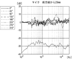
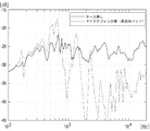
図15〜図18は、マイクロフォンの位置をケースの前部(0°方位角)寄りにして取得された測定値の詳細を示す。これらの測定値により、マイクロフォンとケース前方縁との間の距離が測定された性能に及ぼす影響を考察する。図15の黒丸は、マイクロフォン#6の方位角0°での測定値において生じる5〜6kHzにおけるノッチを示す。このノッチは、マイクロフォンの場所がさらに奥に移動するにしたがって埋まる。これらの結果から、マイクロフォンの最適な場所は、ケース前方縁から20mmと50mmとの間であると思われる。テーブルに配置された単一の表面実装マイクロフォンの測定値により、マイクロフォン応答は線形か無指向性であることが確認された。マイクロフォンのノイズフロアを、図19に示す、テーブルトップにおける65dBSPLのILTASS(長期スピーチスペクトル)ノイズの測定値と比較した。これらの結果は、この表面実装マイクロフォンが目的とする用途について許容可能な自己雑音特性を有することを示している。ケースに取り付けたマイクロフォンの測定値は、マイクロフォンの信号の固体伝搬ノイズ汚染および/または空気伝播ノイズ汚染を示している。以下の図20に示す、ケースに取り付けたマイクロフォンのポーラ測定は、固体伝搬ノイズおよび/または空気伝播ノイズによる遅延信号の追加から生じた強い櫛型フィルタリング作用を示している。汚染源をよりよく理解するため、以下を含む、このプロトタイプの様々な変形例を評価した。
−発泡体を有するケースからマイクロフォンを分離する
−テーブルから装置を分離する
−ケースに成形用プラスチックを充填する
−吸収性ウール層をキャビティ内に挿入する
−吸収性発泡体層をキャビティ内に挿入する
図21〜図26は、表面実装マイクロフォンをテーブル上に直接配置して行った「ケース無し」基準測定と、各ケース内測定との比較を示す。最も影響が大きかった変形例は、図26に示す内蔵発泡体を有するケースであった。この変形例は、以下のいくつかの点で性能を向上させる。第1には、ケースの前面パネルおよび背面パネルをしっかりと押圧してパネル共振の制振効果をもたらし、第2には、キャビティ内の空気伝播放射を吸収する。結果として得られる応答は、他のすべての図面で見られる櫛型フィルタリング作用を含まない。
製品は、試験を行ったプロトタイプに匹敵するような大きさの内部キャビティを好ましくは有さず、パネル共振は、ケース内で面一に取り付けられたスマートフォンの存在により制振されやすくなる。しかし、表面実装マイクロフォンは、空気伝播ノイズ汚染および固体伝搬ノイズ汚染の両方に対して非常に感受性が高い。マイクロフォンは、ケースからの振動絶縁性および吸収性発泡体によって処理が施された隣接内部キャビティを好ましくは含む。
15 to 18 show the details of the measurement values obtained with the microphone position closer to the front part (0° azimuth angle) of the case. With these measurements we consider the effect of the distance between the microphone and the front edge of the case on the measured performance. The black circles in FIG. 15 show the notches at 5-6 kHz that occur in the measurements of
-Separate the microphone from the case with the foam-separate the device from the table-fill the case with molding plastic-insert the absorbent wool layer into the cavity-insert the absorbent foam layer into the cavity 21-26 show a comparison of the "no case" reference measurements made with the surface mount microphone placed directly on the table and the measurements within each case. The most influential modification was the case with the built-in foam shown in FIG. This variation improves performance in several ways. First, it firmly presses the front and back panels of the case to provide a damping effect of panel resonance, and second, it absorbs airborne radiation in the cavity. The resulting response does not include the comb filtering effect found in all other figures.
The product preferably does not have internal cavities of comparable size to the prototypes tested, and panel resonances are more likely to be damped by the presence of the smartphone mounted flush within the case. However, surface mount microphones are very sensitive to both airborne and solid-borne noise pollution. The microphone preferably includes an adjacent internal cavity that has been treated with vibration insulating and absorbent foam from the case.
これらの結果により、図1A〜図1Eの好適な実施形態によってマイクロフォン配置に関して最良の音響性能が得られることが確認される。 These results confirm that the preferred embodiment of FIGS. 1A-1E provides the best acoustic performance for microphone placement.
上記設計にマイクロプロジェクタを組み込むことが可能である。プロジェクタは、耳の裏にあってもよく、また、眼鏡のツルに沿って延びる光導波管に接続することができ、そして、所望の画像および/またはテキストをユーザの眼鏡の表面に、次いで瞳を通過させて目に投射する。これは、眼鏡にビームスプリッタのコーティングを設けるかあるいは設けることなく行うことができる。これにより、眼鏡を通して画像およびテキストを見ること、加えて、所望のシーンを見ることが可能となる。一実施形態において、この機構は視野から隠れている。ビームスプリッタは、特殊ガラスレンズ、コーティングおよび/または眼鏡用のプラスチックオーバーレイによって実現することができる。 It is possible to incorporate a microprojector into the above design. The projector may be behind the ear and may be connected to an optical waveguide that extends along the temples of the spectacles, and the desired image and/or text may be placed on the surface of the user's spectacles and then the pupil. To pass through and project to the eye. This can be done with or without the beam splitter coating on the glasses. This allows viewing the images and text through the glasses as well as the desired scene. In one embodiment, this feature is hidden from view. The beamsplitter can be realized by special glass lenses, coatings and/or plastic overlays for spectacles.
図27は、聴力を改善するためのシステム100のシステム概要を示す。
FIG. 27 shows a system overview of a
システム100は、サーバシステム104と、入力システム106と、出力システム108と、複数のクライアントシステム110、114、116、118および120と、通信ネットワーク112と、携帯型無線装置122とを含み得る。他の実施形態において、システム100は、追加の構成要素を含んでいてもよく、かつ/あるいは上記の構成要素のすべてを含まなくてもよい。
サーバシステム104は、1つまたは複数のサーバを含み得る。1つのサーバシステム104は、任意の関連ソフトウェアまたは非一時的記憶媒体の販売業者の所有物であってもよい。
The
入力システム106は、サーバシステム104に入力を行うために利用されてもよく、キーボードシステム、マウスシステム、トラックボールシステム、トラックパッドシステム、携帯型システム上の複数のボタン、モバイルシステム、スキャナシステム、無線受信機、マイクロフォンシステム、音声システムへの接続、ならびに/または、コンピュータシステム、イントラネットおよび/もしくはインターネットへの接続および/もしくはインターフェースシステム(すなわち、赤外線データ通信機能標準化協会規格(IrDA)、ユニバーサルシリアルバスすなわち(USB))のうちのいずれか1つ、いくつか、任意の組み合わせまたはすべてを含み得る。
The
出力システム108は、サーバシステム104からの出力を受信するために利用されてもよい。また、出力システム108は、モニタシステム、無線送信機、携帯型ディスプレイシステム、モバイルディスプレイシステム、プリンタシステム、スピーカシステム、音声システムに対する接続もしくはインターフェースシステム、1つもしくは複数の周辺機器に対するインターフェースシステム、ならびに/または、コンピュータシステム、イントラネットおよび/もしくはインターネットに対する接続もしくはインターフェースシステムのうちのいずれか1つ、いくつか、任意の組み合わせまたはすべてを含み得る。
システム100は、情報提供ウェブサイト(図示せず)であってもよいサーバシステム104への接続方法の変形例のいくつかを示す。サーバシステム104は、複数のクライアントシステム110、114、116、118および120に直接接続および/または無線接続されてもよく、通信ネットワーク112を介して接続されてもよい。クライアントシステム120は、クライアントシステム118を介してサーバシステム104に接続されてもよい。通信ネットワーク112は、1つまたは複数のローカルエリアネットワーク(LAN)、広域ネットワーク(WAN)、無線ネットワーク、電話ネットワーク、インターネットおよび/または他のネットワークのうちのいずれか1つまたは任意の組み合わせであってよい。通信ネットワーク112は、1つまたは複数の無線ポータルを含み得る。クライアントシステム110、114、116、118および120は、エンドユーザがサーバシステム104にアクセスするために利用し得る任意のシステムであってよい。たとえば、クライアントシステム110、114、116、118および120は、パーソナルコンピュータ、ワークステーション、ラップトップコンピュータ、ゲーム機、携帯型ネットワーク対応式のオーディオプレーヤー/ビデオプレーヤー、モバイル装置および/または他の任意のネットワーク機器であってもよい。
クライアントシステム120は、通信ネットワーク112と別のシステムとの組み合わせを介してサーバシステム104にアクセスしてもよく、この別のシステムは、本例においてはクライアントシステム118であってもよい。クライアントシステム120は、携帯電話、タブレットまたは携帯型ネットワーク対応式のオーディオプレーヤーまたは音楽プレーヤーといった、ネットワークコンテンツにアクセスするためにも利用され得る携帯型無線装置122であってもよい。クライアントシステム120は、オペレーティングシステムを有する携帯電話すなわちスマートフォン124またはオペレーティングシステムを有するタブレットすなわちIPAD(登録商標)装置126であってもよい。
The
図28は、クライアントシステム200のブロック図を示す。
FIG. 28 shows a block diagram of the
クライアントシステム200は、出力システム202、入力システム204、メモリシステム206、プロセッサシステム208、通信システム212、入出力システム214、ウェブサイト216および無線ポータル218を含み得る。クライアントシステム200の他の実施形態は、上記構成要素のすべてを含んでいなくてもよく、かつ/または上記の構成要素に加えてもしくはその代わりに他の実施形態を有していてもよい。
The
クライアントシステム200は、図1のネットワーク装置のうちの1つとして利用され得るクライアントシステム110、114、116、118、120および/または携帯型無線装置122、スマートフォン124もしくはIPAD(登録商標)装置126のうちのいずれか1つであってよい。他の実施形態において、クライアントシステム200は、追加の構成要素を含んでいてもよく、かつ/または上記の構成要素をすべて含まなくてもよい。出力システム202は、モニタシステム、無線送信機、携帯型ディスプレイシステム、プリンタシステム、スピーカシステム、音声システムへの接続もしくはインターフェースシステム、周辺装置へのインターフェースシステム、ならびに/またはコンピュータシステム、イントラネットおよび/もしくはインターネットへの接続および/もしくはインターフェースシステムのうちのいずれか1つ、いくつか、任意の組み合わせまたはすべてを含み得る。
入力システム204は、キーボードシステム、マウスシステム、トラックボールシステム、トラックパッドシステム、携帯型システム上の1つもしくは複数のボタン、スキャナシステム、無線受信機、マイクロフォンシステム、音声システムへの接続、ならびに/またはコンピュータシステム、イントラネットおよび/もしくはインターネットへの接続もしくはインターフェースシステム(すなわち、赤外線データ通信機能標準化協会規格(IrDA)、ユニバーサルシリアルバスすなわち(USB))のうちのいずれか1つ、いくつか、任意の組み合わせまたはすべてを含み得る。メモリシステム206は、ハードドライブなどの長期記憶システム、ランダムアクセスメモリなどの短期記憶システム、フロッピードライブまたはリムーバブルドライブおよび/またはフラッシュメモリなどの着脱可能な記憶システムのうちのいずれか1つ、いくつか、任意の組み合わせまたはすべてを含み得る。メモリシステム206は、様々な異なる種類の情報を記憶し得る1つまたは複数の機械可読媒体を含み得る。「機械可読媒体」という用語は、機械によって読み込まれ得る形式で情報を保持するように構造的に構成され得る任意の媒体を指すために使用され得る。機械可読媒体の一例は、コンピュータ可読媒体であり得る。メモリシステム206は、聴力改善用の非一時的記憶媒体を格納していてもよい。
The
プロセッサシステム208は、多数個の並列プロセッサ、単一のプロセッサ、1つもしくは複数中央プロセッサおよび/または1つもしくは複数の特定のタスク専用の専用プロセッサを有するプロセッサのシステム、のうちのいずれか1つ、いくつか、任意の組み合わせまたはすべてを含み得る。プロセッサシステム208は、メモリシステム206に記憶されたプログラムを実施し得る。通信システム212は、出力システム202、入力システム204、メモリシステム206、プロセッサシステム208および/または入出力システム214を互いに通信可能にリンクし得る。通信システム212は、1つもしくは複数の電気ケーブル、光ファイバケーブル、および/または空気もしくは水を介して信号を送信する手段(すなわち、無線通信)等のうちのいずれか1つ、いくつか、任意の組み合わせまたはすべてを含み得る。空気および/または水を介して信号を送信する手段のいくつかの例には、赤外線波および/もしくは電波などの電磁波を送信するためのシステムならびに/または音波を送信するためのシステムが含まれ得る。
入出力システム214は、入力装置および出力装置としての二重の機能を有する装置を含み得る。たとえば、入出力システム214は、1つまたは複数のタッチセンシティブスクリーンを含んでいてもよく、タッチセンシティブスクリーンは、画像を表示し、したがって、出力装置であり得るとともに、画面が指またはスタイラスによって押圧されると入力を受け付けることができる。タッチセンシティブスクリーンは、熱、静電容量および/または圧力に対して感受性を有していてもよい。入出力装置のうちの1つまたは複数が、スタイラスによって発生する電圧または電流に対して感受性を有していてもよい。入出力システム214は、必要に応じて設けられるものであり、出力システム202および/または出力装置204に加えてまたはその代わりに利用されてもよい。
The input/
クライアントシステム110、114、116、118、120および携帯型無線装置122は、通信システム212に直接結合され得るウェブサイト216または無線ポータル218に結合されていてもよい。ウェブサイト216または無線ポータル218はいずれもまた、非一時的記憶媒体と、ウェブサイトを維持し、ウェブサイトへのアクセスを可能にし、ウェブサイトを運営するためのウェブサイトモジュール(図示せず)とを含み得る。
図29は、聴力を改善するために利用され得るサーバシステム104のブロック図を示す。サーバシステム104は、電源220と、出力システム230と、入力システム240と、オペレーティングシステム251を記憶し得るメモリシステム250と、通信モジュール252と、ウェブブラウザモジュール253と、ウェブサーバアプリケーション254と、聴力改善用の非一時的記憶媒体256とを含み得る。サーバシステム104は、プロセッサシステム260、通信インターフェース270、通信システム275、および入出力システム280も含み得る。他の実施形態において、サーバシステム104は、追加の構成要素を含んでいてもよく、かつ/または上記の構成要素のすべてを含まなくてもよい。
FIG. 29 shows a block diagram of a
出力システム230は、モニタシステム、携帯型ディスプレイシステム、プリンタシステム、スピーカシステム、音声システムへの接続もしくはインターフェースシステム、1つもしくは複数の周辺機器へのインターフェースシステム、ならびに/またはコンピュータシステム、イントラネットおよび/もしくはインターネットへの接続および/もしくはインターフェースシステムのうちのいずれか1つ、いくつか、任意の組み合わせまたはすべてを含み得る。
The
入力システム240は、キーボードシステム、マウスシステム、トラックボールシステム、トラックパッドシステム、携帯型システム上の1つもしくは複数のボタン、スキャナシステム、マイクロフォンシステム、音声システムへの接続、ならびに/またはコンピュータシステム、イントラネットおよび/もしくはインターネットへの接続および/もしくはインターフェースシステム(すなわち、IrDA、USB)のうちのいずれか1つ、いくつか、任意の組み合わせまたはすべてを含み得る。
The
メモリシステム250は、ハードドライブなどの長期記憶システム、ランダムアクセスメモリなどの短期記憶システム、またはフロッピードライブもしくはリムーバブルドライブおよび/またはフラッシュメモリなどの着脱可能な記憶システムのうちのいずれか1つ、いくつか、任意の組み合わせまたはすべて含み得る。メモリシステム250は、様々な異なる種類の情報を記憶し得る1つまたは複数の機械可読媒体を含み得る。「機械可読媒体」という用語は、機械によって読み取り可能な情報を保持することが可能な任意の媒体を指すために利用され得る。機械可読媒体の一例は、非一時的記憶媒体などのコンピュータ可読媒体であり得る。メモリシステム250は、聴力を改善するための1つまたは複数の機械命令を記憶していてもよい。オペレーティングシステム251は、システム100のすべてのソフトウェアおよびハードウェアを制御し得る。通信モジュール252は、サーバシステム104が通信ネットワーク112上で通信を行うことを可能にし得る。ウェブブラウザモジュール253は、インターネットのブラウジングを可能にし得る。ウェブサーバアプリケーション254は、ウェブページをリクエストするクライアントシステムに対して複数のウェブページを提供し、それにより、インターネット上でのブラウジングを容易にし得る。聴力改善用の非一時的記憶媒体256は、メモリシステム250にあってもよい。プロセッサシステム260は、多数個の並列プロセッサ、単一のプロセッサ、1つもしくは複数の中央プロセッサおよび/または1つもしくは複数の特定のタスク専用の専用プロセッサを有するプロセッサのシステム、のうちのいずれか1つ、いくつか、任意の組み合わせまたはすべてを含み得る。プロセッサシステム260は、メモリシステム250に記憶された機械命令を実行してもよい。
The memory system 250 may be any one or more of a long-term storage system such as a hard drive, a short-term storage system such as random access memory, or a removable storage system such as a floppy drive or removable drive and/or flash memory. , Any combination or all. Memory system 250 may include one or more machine-readable media that may store a variety of different types of information. The term "machine-readable medium" can be used to refer to any medium that can carry information that can be read by a machine. An example of a machine-readable medium may be a computer-readable medium such as a non-transitory storage medium. The memory system 250 may store one or more machine instructions for improving hearing. Operating system 251 may control all software and hardware of
別の実施形態において、通信インターフェース270は、サーバシステム104が通信ネットワーク112とインターフェース接続を行うことを可能にしてもよい。この実施形態において、出力システム230は、通信インターフェース270に通信を送信してもよい。通信システム275は、出力システム230、入力システム240、メモリシステム250、プロセッサシステム260および/または入出力システム280を互いに通信可能にリンクする。通信システム275は、1つまたは複数の電気ケーブル、光ファイバケーブルおよび/または空気もしくは水を介した信号の送信(すなわち、無線通信)等のうちの1つ、いくつか、任意の組み合わせまたはすべてを含み得る。空気および/または水を介した信号の送信のいくつかの例には、赤外線波および/もしくは電波などの電磁波を送信するためのシステムならびに/または音波を送信するためのシステムが含まれ得る。
In another embodiment,
入出力システム280は、入力装置および出力装置としての二重の機能を有する装置を含み得る。たとえば、入出力システム280は、1つまたは複数のタッチセンシティブスクリーンを含んでいてもよく、タッチセンシティブスクリーンは、画像を表示し、したがって、出力装置であり得るとともに、画面が指またはスタイラスによって押圧されると入力を受け付けることができる。タッチセンシティブスクリーンは、熱および/または圧力に対して感受性を有していてもよい。入出力装置のうちの1つまたは複数が、スタイラスによって発生する電圧または電流に対して感受性を有していてもよい。入出力システム280は、必要に応じて設けられるものであり、出力システム230および/または入力システム240に加えてまたはその代わりに利用されてもよい。
The input/
本発明を上記実施形態に関して説明したが、当業者であれば、本発明が説明された実施形態に限定されるものではないことを理解するであろう。本発明は、添付の特許請求の範囲の趣旨および範囲において、変形および変更して実施され得る。よって、上記の説明は、例示であって、本発明を限定するものではなく、本発明は添付の請求の範囲によってのみ定義される。 Although the present invention has been described in terms of the above embodiments, those skilled in the art will understand that the invention is not limited to the described embodiments. The present invention may be practiced with modification and alteration within the spirit and scope of the appended claims. Therefore, the above description is illustrative and not limiting the invention, which is defined only by the appended claims.
Claims (32)
エンクロージャの外部から音響信号を受信し、マイクロフォン出力信号を生成するための複数のマイクロフォンであって、同一平面上に三角形を成すように配置されるマイクロフォンと、
ユーザの位置に関する情報を受信し、前記ユーザの頭部の位置を計算するユーザ位置処理回路と、
前記マイクロフォン出力信号および前記ユーザの頭部の位置に関する情報を受信し、前記マイクロフォンによって受信され、前記ユーザの聴覚欠損プロファイルに合わせて調整した前記音響信号と比較して音響音質が向上したオーディオ出力信号を生成する処理回路であって、ノイズ低減のために、前記ユーザーの位置によって少なくとも1つの前記マイクロフォンが無効化される、処理回路と、
オーディオ出力信号を前記ユーザに提供する補助聴覚装置と
を備えるシステム。 A system for improving hearing,
A plurality of microphones for receiving an acoustic signal from the outside of the enclosure and generating a microphone output signal, wherein the microphones are arranged so as to form a triangle on the same plane ,
A user position processing circuit that receives information about the position of the user and calculates the position of the user's head;
An audio output signal that receives information about the microphone output signal and the position of the user's head, is received by the microphone, and has improved acoustic sound quality compared to the acoustic signal adjusted to the hearing loss profile of the user. A processing circuit for generating at least one of the microphones depending on a position of the user for noise reduction ;
A hearing aid that provides an audio output signal to the user.
前記ユーザの頭部の光学画像を取得するための視野を有するカメラと、
ユーザの頭部の位置および注視の向きを計算する位置処理回路とを含み、
前記位置および注視の向きは、前記オーディオ出力信号の方向、強度、角度および品質のうち少なくとも1つを最適化するために前記処理回路によって受信される、請求項1に記載のシステム。 The user position processing circuit is
A camera having a field of view for obtaining an optical image of the user's head,
And a position processing circuit that calculates the position of the user's head and the direction of the gaze,
The system of claim 1, wherein the position and gaze orientation are received by the processing circuit to optimize at least one of a direction, intensity, angle and quality of the audio output signal.
スマートフォンを、前記スマートフォンを持つユーザを前記スマートフォンに含まれるカメラで見ることができる位置で保持して、前記ユーザの場所を検出するステップと、
前記スマートフォンに含まれる複数のビーム形成マイクロフォンであって、同一平面上に三角形を成すよう配置されているマイクロフォンによってオーディオ信号を取得するステップと、
前記複数のビーム形成マイクロフォンの角度および強度を定めるビーム形成アルゴリズムを用いる前記ビーム形成マイクロフォンのうち少なくとも1つから処理された向上したオーディオ信号によって、前記ユーザに聴覚情報をフィードバックするステップであって、ノイズ低減のために、前記ユーザの位置によって少なくとも1つのビーム形成マイクロフォンが無効化される、ステップとを含む方法。 A method for improving hearing,
Holding a smartphone in a position where a user with the smartphone can be seen by a camera included in the smartphone, and detecting the location of the user;
A plurality of beam forming microphones included in the smartphone, wherein the microphones are arranged to form a triangle on the same plane;
The audio signal is improved, which is processed from at least one of the beam forming microphone using beamforming algorithm to determine the angle and intensity of the plurality of beamforming microphone, comprising the steps of feedback audible information to the user, the noise For reduction, at least one beamforming microphone is disabled by the position of the user .
スマートフォンに含まれる複数のビーム形成マイクロフォンであって、同一平面上に三角形を成すよう配置されているマイクロフォンによってオーディオ信号を受信するステップと、
前記ユーザが見えるように焦点が合わされかつ倍率が拡大されたカメラを有する前記スマートフォンによって、前記ユーザの位置を監視するステップと、
前記複数のビーム形成マイクロフォンを用いて処理された向上したオーディオ信号によって、前記ユーザに聴覚情報をフィードバックするステップであって、ノイズ低減のために、前記ユーザの位置によって少なくとも1つのビーム形成マイクロフォンが無効化される、ステップと
を含む非一時的コンピュータ記憶媒体。 A non-transitory computer storage medium having instructions stored thereon that, when executed, carry out a method for providing an enhanced audio signal to a user, the method comprising:
A plurality of beam forming microphones included in the smartphone, the microphones being arranged on the same plane so as to form a triangle ;
Monitoring the position of the user by the smartphone having a camera that is focused and magnified so that the user can see;
Feedback of auditory information to the user by an enhanced audio signal processed using the plurality of beamforming microphones , wherein at least one beamforming microphone is disabled depending on the position of the user for noise reduction. And a non-transitory computer storage medium including steps .
Applications Claiming Priority (3)
| Application Number | Priority Date | Filing Date | Title |
|---|---|---|---|
| US201562116231P | 2015-02-13 | 2015-02-13 | |
| US62/116,231 | 2015-02-13 | ||
| PCT/US2016/018132 WO2016131064A1 (en) | 2015-02-13 | 2016-02-16 | System and method for improving hearing |
Publications (3)
| Publication Number | Publication Date |
|---|---|
| JP2018511212A JP2018511212A (en) | 2018-04-19 |
| JP2018511212A5 JP2018511212A5 (en) | 2019-03-22 |
| JP6738342B2 true JP6738342B2 (en) | 2020-08-12 |
Family
ID=56615706
Family Applications (1)
| Application Number | Title | Priority Date | Filing Date |
|---|---|---|---|
| JP2017542487A Expired - Fee Related JP6738342B2 (en) | 2015-02-13 | 2016-02-16 | System and method for improving hearing |
Country Status (6)
| Country | Link |
|---|---|
| US (1) | US10856071B2 (en) |
| EP (1) | EP3257266A4 (en) |
| JP (1) | JP6738342B2 (en) |
| AU (1) | AU2016218989B2 (en) |
| CA (1) | CA2975955A1 (en) |
| WO (1) | WO2016131064A1 (en) |
Families Citing this family (21)
| Publication number | Priority date | Publication date | Assignee | Title |
|---|---|---|---|---|
| US10856068B2 (en) | 2015-09-16 | 2020-12-01 | Apple Inc. | Earbuds |
| US9716937B2 (en) * | 2015-09-16 | 2017-07-25 | Apple Inc. | Earbuds with biometric sensing |
| WO2017194084A1 (en) * | 2016-05-09 | 2017-11-16 | Advanced Bionics Ag | Neural stimulation system |
| WO2018048846A1 (en) | 2016-09-06 | 2018-03-15 | Apple Inc. | Earphone assemblies with wingtips for anchoring to a user |
| US10512750B1 (en) | 2016-12-28 | 2019-12-24 | X Development Llc | Bone conduction speaker patch |
| US10284982B1 (en) | 2016-12-28 | 2019-05-07 | X Development Llc | Bone conduction speaker patch |
| US10133544B2 (en) | 2017-03-02 | 2018-11-20 | Starkey Hearing Technologies | Hearing device incorporating user interactive auditory display |
| JP2018191145A (en) * | 2017-05-08 | 2018-11-29 | オリンパス株式会社 | Voice collection device, voice collection method, voice collection program, and dictation method |
| WO2019013811A1 (en) | 2017-07-14 | 2019-01-17 | Hewlett-Packard Development Company, L.P. | Microwave image processing to steer beam direction of microphone array |
| US10157628B1 (en) * | 2017-11-07 | 2018-12-18 | Fortemedia, Inc. | Sound identification device with microphone array |
| US10540015B2 (en) * | 2018-03-26 | 2020-01-21 | Chian Chiu Li | Presenting location related information and implementing a task based on gaze and voice detection |
| CN112544089B (en) * | 2018-06-07 | 2023-03-28 | 索诺瓦公司 | Microphone device providing audio with spatial background |
| CN108831472B (en) * | 2018-06-27 | 2022-03-11 | 中山大学肿瘤防治中心 | Artificial intelligent sounding system and sounding method based on lip language recognition |
| JP7127683B2 (en) * | 2018-06-27 | 2022-08-30 | ヤマハ株式会社 | Sound equipment and information management system |
| EP3945735A1 (en) | 2020-07-30 | 2022-02-02 | Koninklijke Philips N.V. | Sound management in an operating room |
| US11290837B1 (en) * | 2020-10-23 | 2022-03-29 | Facebook Technologies, Llc | Audio system using persistent sound source selection for audio enhancement |
| EP4093046A1 (en) * | 2021-05-21 | 2022-11-23 | Nokia Technologies Oy | Multi-microphone audio capture |
| US11478184B1 (en) | 2021-09-14 | 2022-10-25 | Applied Cognition, Inc. | Non-invasive assessment of glymphatic flow and neurodegeneration from a wearable device |
| US11689841B2 (en) * | 2021-09-29 | 2023-06-27 | Microsoft Technology Licensing, Llc | Earbud orientation-based beamforming |
| WO2023237923A1 (en) * | 2022-06-08 | 2023-12-14 | Wehear Hearing Solutions Llp | A sound receiver watch for non-surgical hearing aid |
| DE102022121636A1 (en) * | 2022-08-26 | 2024-02-29 | Telefónica Germany GmbH & Co. OHG | System, method, computer program and computer-readable medium |
Family Cites Families (46)
| Publication number | Priority date | Publication date | Assignee | Title |
|---|---|---|---|---|
| JPS61234699A (en) * | 1985-04-10 | 1986-10-18 | Tokyo Tatsuno Co Ltd | Hearing aid |
| EP0845958B1 (en) | 1995-07-21 | 2003-05-28 | Stethtech Corporation | Electronic stethoscope |
| JPH09327097A (en) * | 1996-06-07 | 1997-12-16 | Nec Corp | Hearing aid |
| DE69904822T2 (en) * | 1999-10-07 | 2003-11-06 | Zlatan Ribic | Method and arrangement for recording sound signals |
| JP2001292212A (en) * | 2000-04-07 | 2001-10-19 | Mitsubishi Electric Corp | Portable telephone set |
| US8116489B2 (en) | 2004-10-01 | 2012-02-14 | Hearworks Pty Ltd | Accoustically transparent occlusion reduction system and method |
| WO2007052185A2 (en) * | 2005-11-01 | 2007-05-10 | Koninklijke Philips Electronics N.V. | Hearing aid comprising sound tracking means |
| EP2030476B1 (en) | 2006-06-01 | 2012-07-18 | Hear Ip Pty Ltd | A method and system for enhancing the intelligibility of sounds |
| US8526632B2 (en) * | 2007-06-28 | 2013-09-03 | Microsoft Corporation | Microphone array for a camera speakerphone |
| US9445193B2 (en) | 2008-07-31 | 2016-09-13 | Nokia Technologies Oy | Electronic device directional audio capture |
| US20100074460A1 (en) * | 2008-09-25 | 2010-03-25 | Lucent Technologies Inc. | Self-steering directional hearing aid and method of operation thereof |
| US8301193B1 (en) * | 2008-11-03 | 2012-10-30 | Sprint Communications Company L.P. | Differential planes for video I/O in a hearing impaired application |
| CN102204281B (en) | 2008-11-05 | 2015-06-10 | 希尔Ip有限公司 | A system and method for producing a directional output signal |
| US8154588B2 (en) * | 2009-01-14 | 2012-04-10 | Alan Alexander Burns | Participant audio enhancement system |
| US20100317413A1 (en) * | 2009-06-15 | 2010-12-16 | Qing Song Tan | Portable phone holder and solar charger |
| US8947978B2 (en) | 2009-08-11 | 2015-02-03 | HEAR IP Pty Ltd. | System and method for estimating the direction of arrival of a sound |
| US8538049B2 (en) * | 2010-02-12 | 2013-09-17 | Audiotoniq, Inc. | Hearing aid, computing device, and method for selecting a hearing aid profile |
| US8654999B2 (en) * | 2010-04-13 | 2014-02-18 | Audiotoniq, Inc. | System and method of progressive hearing device adjustment |
| TWI401015B (en) * | 2010-06-08 | 2013-07-01 | Htc Corp | Handheld device having linkage supporter |
| JP2012029209A (en) * | 2010-07-27 | 2012-02-09 | Hitachi Ltd | Audio processing system |
| WO2012017270A1 (en) * | 2010-08-05 | 2012-02-09 | Nokia Corporation | An apparatus |
| US9396717B2 (en) | 2010-11-18 | 2016-07-19 | HEAR IP Pty Ltd. | Systems and methods for reducing unwanted sounds in signals received from an arrangement of microphones |
| WO2012083989A1 (en) * | 2010-12-22 | 2012-06-28 | Sony Ericsson Mobile Communications Ab | Method of controlling audio recording and electronic device |
| US20130177166A1 (en) * | 2011-05-27 | 2013-07-11 | Sony Ericsson Mobile Communications Ab | Head-related transfer function (hrtf) selection or adaptation based on head size |
| US20130028443A1 (en) * | 2011-07-28 | 2013-01-31 | Apple Inc. | Devices with enhanced audio |
| DE102011085361A1 (en) * | 2011-10-28 | 2013-05-02 | Sennheiser Electronic Gmbh & Co. Kg | microphone device |
| US9104048B2 (en) * | 2012-01-25 | 2015-08-11 | International Business Machines Corporation | Three dimensional image projector with single modulator |
| US8781142B2 (en) * | 2012-02-24 | 2014-07-15 | Sverrir Olafsson | Selective acoustic enhancement of ambient sound |
| EP2832111B1 (en) * | 2012-03-26 | 2018-05-23 | University of Surrey | Acoustic source separation |
| US9746916B2 (en) | 2012-05-11 | 2017-08-29 | Qualcomm Incorporated | Audio user interaction recognition and application interface |
| US20140189586A1 (en) * | 2012-12-28 | 2014-07-03 | Spritz Technology Llc | Methods and systems for displaying text using rsvp |
| US8995698B2 (en) * | 2012-07-27 | 2015-03-31 | Starkey Laboratories, Inc. | Visual speech mapping |
| KR102060712B1 (en) * | 2013-01-31 | 2020-02-11 | 엘지전자 주식회사 | Mobile terminal and method for operating the same |
| US10347269B2 (en) | 2013-03-12 | 2019-07-09 | Hear Ip Pty Ltd | Noise reduction method and system |
| US10365716B2 (en) * | 2013-03-15 | 2019-07-30 | Interaxon Inc. | Wearable computing apparatus and method |
| US9280972B2 (en) | 2013-05-10 | 2016-03-08 | Microsoft Technology Licensing, Llc | Speech to text conversion |
| EP3917167A3 (en) | 2013-06-14 | 2022-03-09 | Oticon A/s | A hearing assistance device with brain computer interface |
| US9596437B2 (en) * | 2013-08-21 | 2017-03-14 | Microsoft Technology Licensing, Llc | Audio focusing via multiple microphones |
| US20150117695A1 (en) * | 2013-10-28 | 2015-04-30 | Aliphcom | Orienting earbuds and earbud systems |
| US20150118959A1 (en) * | 2013-10-28 | 2015-04-30 | Nicolas Jean Petit | Platform framework for wireless media device simulation and design |
| US8891800B1 (en) | 2014-02-21 | 2014-11-18 | Jonathan Everett Shaffer | Earbud charging case for mobile device |
| KR20200092424A (en) * | 2014-03-03 | 2020-08-03 | 아이웨이 비전 엘티디. | Eye projection system |
| US9426568B2 (en) * | 2014-04-15 | 2016-08-23 | Harman International Industries, LLC | Apparatus and method for enhancing an audio output from a target source |
| US20150382129A1 (en) * | 2014-06-30 | 2015-12-31 | Microsoft Corporation | Driving parametric speakers as a function of tracked user location |
| US10284956B2 (en) * | 2015-06-27 | 2019-05-07 | Intel Corporation | Technologies for localized audio enhancement of a three-dimensional video |
| US20170243582A1 (en) * | 2016-02-19 | 2017-08-24 | Microsoft Technology Licensing, Llc | Hearing assistance with automated speech transcription |
-
2016
- 2016-02-16 CA CA2975955A patent/CA2975955A1/en not_active Abandoned
- 2016-02-16 US US15/045,199 patent/US10856071B2/en active Active
- 2016-02-16 AU AU2016218989A patent/AU2016218989B2/en active Active
- 2016-02-16 EP EP16750075.0A patent/EP3257266A4/en active Pending
- 2016-02-16 WO PCT/US2016/018132 patent/WO2016131064A1/en active Application Filing
- 2016-02-16 JP JP2017542487A patent/JP6738342B2/en not_active Expired - Fee Related
Also Published As
| Publication number | Publication date |
|---|---|
| AU2016218989A1 (en) | 2017-08-17 |
| CA2975955A1 (en) | 2016-08-18 |
| EP3257266A1 (en) | 2017-12-20 |
| US20160249141A1 (en) | 2016-08-25 |
| WO2016131064A1 (en) | 2016-08-18 |
| US10856071B2 (en) | 2020-12-01 |
| EP3257266A4 (en) | 2018-10-03 |
| JP2018511212A (en) | 2018-04-19 |
| AU2016218989B2 (en) | 2020-09-10 |
Similar Documents
| Publication | Publication Date | Title |
|---|---|---|
| JP6738342B2 (en) | System and method for improving hearing | |
| US10448139B2 (en) | Selective sound field environment processing system and method | |
| US10405081B2 (en) | Intelligent wireless headset system | |
| US10085091B2 (en) | Ambient volume modification through environmental microphone feedback loop system and method | |
| JP2018511212A5 (en) | ||
| US11706577B2 (en) | Systems and methods for equalizing audio for playback on an electronic device | |
| KR102378762B1 (en) | Directional sound modification | |
| EP2839675B1 (en) | Auto detection of headphone orientation | |
| US9491553B2 (en) | Method of audio signal processing and hearing aid system for implementing the same | |
| US20160157028A1 (en) | Stereophonic focused hearing | |
| EP3275207B1 (en) | Intelligent switching between air conduction speakers and tissue conduction speakers | |
| US8965012B1 (en) | Smart sensing bone conduction transducer | |
| CN109429132A (en) | Earphone system | |
| WO2014061578A1 (en) | Electronic device and acoustic reproduction method | |
| EP3067782A1 (en) | Information processing apparatus, control method, and program | |
| CN106302974B (en) | information processing method and electronic equipment | |
| US10306142B2 (en) | Headset | |
| JP6290827B2 (en) | Method for processing an audio signal and a hearing aid system | |
| CN114339562A (en) | Sound modification based on direction of interest | |
| WO2018149073A1 (en) | Noise-cancelling headphone and electronic device | |
| US20220342213A1 (en) | Miscellaneous audio system applications | |
| CN115605944A (en) | Activity-based intelligent transparency | |
| JP6930280B2 (en) | Media capture / processing system |
Legal Events
| Date | Code | Title | Description |
|---|---|---|---|
| A521 | Request for written amendment filed |
Free format text: JAPANESE INTERMEDIATE CODE: A523 Effective date: 20171006 |
|
| A521 | Request for written amendment filed |
Free format text: JAPANESE INTERMEDIATE CODE: A523 Effective date: 20171225 |
|
| RD03 | Notification of appointment of power of attorney |
Free format text: JAPANESE INTERMEDIATE CODE: A7423 Effective date: 20180409 |
|
| A521 | Request for written amendment filed |
Free format text: JAPANESE INTERMEDIATE CODE: A821 Effective date: 20180409 |
|
| A521 | Request for written amendment filed |
Free format text: JAPANESE INTERMEDIATE CODE: A523 Effective date: 20190207 |
|
| A621 | Written request for application examination |
Free format text: JAPANESE INTERMEDIATE CODE: A621 Effective date: 20190207 |
|
| A131 | Notification of reasons for refusal |
Free format text: JAPANESE INTERMEDIATE CODE: A131 Effective date: 20200128 |
|
| A521 | Request for written amendment filed |
Free format text: JAPANESE INTERMEDIATE CODE: A523 Effective date: 20200427 |
|
| TRDD | Decision of grant or rejection written | ||
| A01 | Written decision to grant a patent or to grant a registration (utility model) |
Free format text: JAPANESE INTERMEDIATE CODE: A01 Effective date: 20200623 |
|
| A61 | First payment of annual fees (during grant procedure) |
Free format text: JAPANESE INTERMEDIATE CODE: A61 Effective date: 20200717 |
|
| R150 | Certificate of patent or registration of utility model |
Ref document number: 6738342 Country of ref document: JP Free format text: JAPANESE INTERMEDIATE CODE: R150 |
|
| LAPS | Cancellation because of no payment of annual fees |