JP6737005B2 - Burner - Google Patents
Burner Download PDFInfo
- Publication number
- JP6737005B2 JP6737005B2 JP2016126699A JP2016126699A JP6737005B2 JP 6737005 B2 JP6737005 B2 JP 6737005B2 JP 2016126699 A JP2016126699 A JP 2016126699A JP 2016126699 A JP2016126699 A JP 2016126699A JP 6737005 B2 JP6737005 B2 JP 6737005B2
- Authority
- JP
- Japan
- Prior art keywords
- burner
- flame holding
- secondary air
- central axis
- holding plate
- Prior art date
- Legal status (The legal status is an assumption and is not a legal conclusion. Google has not performed a legal analysis and makes no representation as to the accuracy of the status listed.)
- Active
Links
Images


Description
本発明は、バーナに関するものである。 The present invention relates to burners.
下記特許文献1には、バーナの一形態として、石炭焚ボイラに取り付けられた微粉炭バーナが開示されている。この微粉炭バーナは、バーナノズルの先端から微粉炭(燃料)と空気(一次空気)の混合流を、バーナスロートを通して火炉内に噴出し、ウインドボックスから供給される二次空気と混合させながら微粉炭を燃焼させるようになっている。ウインドボックスは、バーナノズルの周りに旋回流を形成し、その旋回流による圧力勾配(旋回流の中心付近とその外側の圧力差)によって、混合流の噴出先に流速ゼロの領域(着火点)を生成している。 Patent Document 1 below discloses a pulverized coal burner attached to a coal-fired boiler as one form of the burner. This pulverized coal burner jets a mixed flow of pulverized coal (fuel) and air (primary air) from the tip of the burner nozzle into the furnace through the burner throat and mixes it with secondary air supplied from the wind box. Is designed to burn. The wind box forms a swirl flow around the burner nozzle, and the pressure gradient (the pressure difference between the center of the swirl flow and the outside thereof) creates a zero flow velocity region (ignition point) at the jet destination of the mixed flow. doing.
ところで、石炭のような化石燃料を燃焼させると、大気汚染の規制対象物である一酸化窒素や二酸化窒素等のNOX(窒素酸化物)が発生する。このため、燃焼域の一部に、窒素分をN2に変換するための酸素濃度が低い還元領域(所謂、蒸し焼き状態となる領域)を形成することが有効である。従来は、二次空気を旋回して供給していたため、二次空気を旋回させない場合に比べて、燃料が二次空気と早く混合されてしまい、十分な還元領域を形成できず、NOXの排出量が上昇してしまうことがあった。 By the way, when a fossil fuel such as coal is burned, NO X (nitrogen oxide) such as nitrogen monoxide and nitrogen dioxide, which are regulated objects of air pollution, are generated. Therefore, it is effective to form, in a part of the combustion region, a reduction region for converting the nitrogen content into N 2 and having a low oxygen concentration (a so-called steaming state region). Conventionally, since the secondary air is swirled and supplied, the fuel is mixed with the secondary air earlier than in the case where the secondary air is not swirled, so that a sufficient reduction region cannot be formed and NO x Emissions sometimes increased.
本発明は、上記問題点に鑑みてなされたものであり、NOXの排出量を低減することができるバーナの提供を目的とする。 The present invention has been made in view of the above problems, and an object of the present invention is to provide a burner that can reduce the emission amount of NO X.
上記の課題を解決するために、本発明は、燃料と空気の混合流を噴出するバーナノズルと、前記バーナノズルの周囲から二次空気を供給する二次空気供給手段と、前記二次空気供給手段から供給された二次空気と衝突して、前記混合流の噴出先に淀み点を形成する保炎部材と、を有する、バーナを採用する。 In order to solve the above problems, the present invention provides a burner nozzle that ejects a mixed flow of fuel and air, a secondary air supply unit that supplies secondary air from the periphery of the burner nozzle, and a secondary air supply unit. A burner having a flame holding member that collides with the supplied secondary air and forms a stagnation point at the jetting destination of the mixed flow.
また、本発明においては、前記保炎部材は、前記二次空気の流れに正対する衝突面が形成された保炎板を有する、という構成を採用する。 Further, in the present invention, the flame holding member includes a flame holding plate having a collision surface that faces the flow of the secondary air.
また、本発明においては、前記衝突面は、前記バーナノズルの中心軸に対し斜めに傾いている、という構成を採用する。 Further, in the present invention, the collision surface is inclined with respect to the central axis of the burner nozzle.
また、本発明においては、前記保炎部材は、前記バーナノズルの中心軸に沿って延在し、その先端に前記保炎板を支持する支持部材を備える、という構成を採用する。 Further, in the present invention, the flame holding member is configured to extend along the central axis of the burner nozzle and to have a support member at the tip thereof for supporting the flame holding plate.
また、本発明においては、前記支持部材には、冷却媒体が流通する冷却流路が形成されている、という構成を採用する。 Further, in the present invention, a configuration is adopted in which a cooling flow path through which a cooling medium flows is formed in the support member.
また、本発明においては、前記保炎板は、前記支持部材に着脱自在に取り付けられている、という構成を採用する。 Further, in the present invention, the flame holding plate is detachably attached to the support member.
また、本発明においては、前記保炎板は、セラミック製である、という構成を採用する。 Further, in the present invention, the flame holding plate is made of ceramic.
また、本発明においては、前記保炎板は、前記混合流の噴出先である火炉内に配置されている、という構成を採用する。 Further, in the present invention, a configuration is adopted in which the flame holding plate is arranged in a furnace which is a jet destination of the mixed flow.
本発明では、バーナノズルの周囲から供給される二次空気と衝突する保炎部材を設けて、バーナノズルの噴出先に淀み点を形成する。この構成によれば、二次空気を旋回させることなく、バーナノズルの噴出先に流速ゼロの領域(着火点)を形成することができる。このため、二次空気を旋回させる機構が不要となり、二次空気を旋回させない結果、燃焼域において酸素濃度が低い還元領域を十分に形成することができる。
したがって、本発明では、NOXの排出量を低減することができる。
In the present invention, the flame holding member that collides with the secondary air supplied from around the burner nozzle is provided to form the stagnation point at the ejection destination of the burner nozzle. With this configuration, it is possible to form a region (ignition point) where the flow velocity is zero at the ejection destination of the burner nozzle without swirling the secondary air. Therefore, a mechanism for swirling the secondary air is not required, and as a result of not swirling the secondary air, it is possible to sufficiently form a reducing region having a low oxygen concentration in the combustion region.
Therefore, in the present invention, the emission amount of NO X can be reduced.
以下、本発明の実施形態のバーナについて図面を参照して説明する。なお、以下の説明では、バーナの一実施形態として微粉炭バーナを例示する。 Hereinafter, a burner according to an embodiment of the present invention will be described with reference to the drawings. In the following description, a pulverized coal burner will be exemplified as one embodiment of the burner.
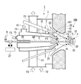
図1は、本発明の実施形態における微粉炭バーナ1の構成図である。
微粉炭バーナ1は、微粉炭(燃料)と空気を火炉100に噴出し、微粉炭を燃焼させるものである。火炉100は、開口部102が形成された炉壁部101を有する。開口部102には、微粉炭バーナ1が設置されている。
FIG. 1 is a configuration diagram of a pulverized coal burner 1 according to an embodiment of the present invention.
The pulverized coal burner 1 injects pulverized coal (fuel) and air into the
微粉炭バーナ1は、バーナノズル2と、バーナダクト3(二次空気供給手段)と、保炎部材4と、を有する。
バーナノズル2は、筒状に形成されており、その先端に微粉炭と空気(一次空気)の混合流F1を噴出する噴出口10が形成されている。本実施形態では、バーナノズル2の噴出口10側がその中心軸Cに向かって絞られて混合流F1を噴出する構成となっている。
The pulverized coal burner 1 has a
The
バーナノズル2は、同心で設けられた筒状のバーナ内筒11とバーナ外筒12とを有する二重筒構造となっている。バーナ内筒11は、長手方向の略中腹部位から先端側へ向かって直径が漸減し、且つ、先端部において直径が急減する絞り部を有する。バーナ外筒12は、バーナ内筒11の外周に同心状に配設され、バーナ内筒11と略相似形で、且つ、先端部において直径が急減する絞り部を有する。
The
バーナ外筒12には、微粉炭入口管13が接続されている。微粉炭入口管13は、バーナ外筒12の内周面の接線方向に混合流F1を供給し、混合流F1を旋回させる。旋回した混合流F1は、バーナ内筒11とバーナ外筒12との間を流通し、リング状に開口する噴出口10から噴出される。
A pulverized
バーナ内筒11の先端には、三次空気F3を噴出する噴出口14が形成されている。三次空気F3は、三次空気入口管15を介してバーナ内筒11に供給される。三次空気入口管15は、バーナノズル2の中心軸Cに沿う軸方向に三次空気F3を供給する。三次空気F3は、バーナ内筒11の内側を軸方向に流通し、円形に開口する噴出口14から噴出される。
A
バーナダクト3は、バーナノズル2の周囲から二次空気F2を供給するものである。バーナダクト3は、バーナノズル2の外側を囲うように設けられ、二次空気F2をバーナノズル2の周囲に導く環状流路20を有する。環状流路20は、バーナ外筒12と開口部102との間に、リング状に形成されている。なお、バーナダクト3の内部は、セパレート板21によって区画されており、二次空気F2は、図示しない他のバーナにも導かれるようになっている。
The burner duct 3 supplies the secondary air F2 from around the
このバーナダクト3は、二次空気F2を旋回させる旋回機構(レジスタベーン等)を備えていない。すなわち、環状流路20を介して供給される二次空気F2は、旋回成分を含んでいない。環状流路20には、点火トーチ22が斜め方向に挿入されている。点火トーチ22は、点火トーチ挿入筒23によって進退自在に支持されている。また、環状流路20には、油バーナ25が斜め方向に挿入されている。油バーナ25は、図示しないエアシリンダ装置に接続され、進退自在に支持されている。
The burner duct 3 does not include a swirl mechanism (register vane or the like) that swirls the secondary air F2. That is, the secondary air F2 supplied via the
保炎部材4は、バーナ内筒11の内側に挿入されている。保炎部材4は、バーナダクト3から供給された二次空気F2と衝突して、混合流F1の噴出先に淀み点Sを形成するものである。保炎部材4は、支持台26によって進退自在に支持されている。支持台26は、バーナ内筒11の中心に挿入された筒部材であり、バーナノズル2の中心軸Cに沿って保炎部材4を支持する。保炎部材4は、エアシリンダ装置27と接続され、バーナノズル2の中心軸C上において位置を調整可能とされている。
The flame holding member 4 is inserted inside the burner
図2は、本発明の実施形態における保炎部材4の(a)先端部における断面構成図、(b)当該先端部を軸方向から視た図である。
図2(a)に示すように、保炎部材4は、保炎板30と、支持部材40と、を有する。
保炎板30は、保炎部材4の先端を形成すると共に、支持部材40に着脱自在に取り付けられている。支持部材40は、図1に示すように、バーナノズル2の中心軸Cに沿って延在し、その先端に保炎板30を支持する。保炎板30は、混合流F1の噴出先である火炉100内に配置されている。
FIG. 2 is (a) a cross-sectional configuration diagram of a tip portion of the flame holding member 4 according to the embodiment of the present invention, and (b) a diagram of the tip portion viewed from the axial direction.
As shown in FIG. 2A, the flame holding member 4 has a
The
保炎板30は、図2(a)に示すように、板部31と、取付部32と、を有する。
板部31には、二次空気F2の流れに正対する衝突面33が形成されている。衝突面33は、バーナノズル2の中心軸Cに対し斜めに傾いている。すなわち、衝突面33は、図1に示すように、バーナノズル2の周囲から中心軸Cに向かって斜めに噴出される二次空気F2の流れに略直交する角度で設けられている。本実施形態の衝突面33は、中心軸Cに対して45°の角度で設けられている。
As shown in FIG. 2A, the
The
板部31は、略円錐台形状を有する。衝突面33は、支持部材40から離間するに従ってその径が漸次増加する。衝突面33は、円筒状の支持部材40の外径と同じ径から、板部31の最大外径の外周面34と同じ径まで増加する。外周面34は、中心軸Cに沿って所定幅で形成されている。外周面34よりも先は、中心軸Cに対して垂直な垂直面35となっている。垂直面35は、図2(b)に示すように、軸方向から視て円形に形成されている。
The
図2(a)に示すように、板部31の垂直面35と反対側の面には、取付部32が一体で形成されている。取付部32は、略円柱形状を有し、板部31の中心に突設されている。取付部32の径は、衝突面33の最小径よりも小さい。この取付部32の周面には、雄ネジ36が形成されている。上記構成の保炎板30は、セラミック製であり、高い耐熱性を有する。
As shown in FIG. 2A, a mounting
支持部材40は、中空棒41と、被取付部42と、を有する。
中空棒41は、支持部材40のベースとなる部材であり、直管パイプ形状を有する。中空棒41の内部には、冷却流路43が形成されている。冷却流路43は、中空棒41の基端から先端まで、中空棒41の長手方向に亘って形成されている。冷却流路43には、図1に示す、バーナ内筒11の外側に突出した支持部材40(中空棒41)の基端から供給される冷却空気A(冷却媒体)が流通する。
The
The
図2(a)に戻り、中空棒41の先端には、冷却流路43を流通する冷却空気Aを、中空棒41の外部に噴出させる空冷用横穴44が形成されている。空冷用横穴44は、中心軸Cに直交する方向に開口している。すなわち、空冷用横穴44から噴出される冷却空気Aの噴出先に、保炎板30は配置されていない。この空冷用横穴44は、図2(b)に示すように、中心軸Cを中心として所定間隔で複数(本実施形態では、90°間隔で4つ)形成されている。
Returning to FIG. 2A, a
被取付部42は、図2(a)に示すように、中空棒41の先端に接合されている。被取付部42は、中空棒41よりも肉厚の筒形状を有する。詳しくは、被取付部42の外径は、中空棒41の外径と同じで、被取付部42の内径は、中空棒41の内径よりも小さい。被取付部42の内周面には、雄ネジ36が螺合可能な雌ネジ45が形成されている。また、被取付部42には、雌ネジ45に螺合した取付部32を固定するための止めねじ用横穴46が形成されている。
The attached
止めねじ用横穴46は、中心軸Cと直交する方向において一箇所に形成されている。止めねじ用横穴46には、止めねじ47が螺合する。止めねじ47は、半径方向から取付部32を押圧することで、保炎板30の回転による螺合解除を規制する。上記構成の支持部材40は、耐熱性を有する金属材、例えばステンレス鋼材から形成されている。なお、火炎に晒される中空棒41の先端部、被取付部42は、ステンレス鋼材の中でも耐熱性の高いもの、例えばSUS310S等から形成することが好ましい。
The set screw
続いて、上記構成の微粉炭バーナ1の動作(作用)について説明する。 Next, the operation (action) of the pulverized coal burner 1 having the above configuration will be described.
微粉炭バーナ1の始動時には、図1に示す油バーナ25による補助燃焼が開始される。この補助燃焼の際には、混合流F1の供給は停止され、二次空気F2及び三次空気F3が供給される。二次空気F2及び三次空気F3は、環状流路20から伸長させた油バーナ25から噴出される油(軽油や重油等)と混合され、点火トーチ22による点火により着火する。この補助燃焼により、火炉100内が所定温度に達したら、混合流F1を供給し、微粉炭による定常燃焼を開始する。この定常燃焼が安定したら、油バーナ25は環状流路20に退避させる。
When the pulverized coal burner 1 is started, auxiliary combustion by the
定常燃焼時、バーナノズル2の周囲からは、二次空気F2が継続して供給される。二次空気F2を供給するバーナダクト3は、二次空気F2を旋回させる機構を備えておらず、二次空気F2には旋回成分が含まれない。そのため、供給される混合流F1は、二次空気F2と合流する領域X1において、従来のように二次空気F2と早く混合されなくなる。一方、従来、二次空気F2の旋回流が担っていた定常燃焼を安定させる流速ゼロの領域X2の形成は、保炎部材4が担う。
During steady combustion, the secondary air F2 is continuously supplied from around the
本実施形態では、バーナノズル2の周囲から供給される二次空気F2と衝突する保炎部材4を設けて、バーナノズル2の噴出先に淀み点Sを形成する。この構成によれば、二次空気F2を旋回させることなく、バーナノズル2の噴出先に淀み点Sによる流速ゼロの領域X1を形成することができる。このため、二次空気F2を旋回させる機構が不要となり、二次空気F2を旋回させない結果、燃焼域において微粉炭と二次空気F2が混合されない酸素濃度が低い還元領域を十分に形成することができる。したがって、本実施形態では、NOXの排出量を低減することができる。
In this embodiment, the flame holding member 4 that collides with the secondary air F2 supplied from the periphery of the
また、保炎部材4は、二次空気F2の流れに正対する衝突面33が形成された保炎板30を有する。この構成によれば、二次空気F2の流れに正対する衝突面33によって二次空気F2の流れを止め易くなり、流速ゼロの淀み点Sを良好に形成することができる。本実施形態の衝突面33は、図1に示すように、バーナノズル2の中心軸Cに対し斜めに傾いているため、バーナノズル2の周囲から中心軸Cに向かって供給される二次空気F2の主流に対し略直交する壁が形成され、淀み点Sを良好に形成することができる。
Further, the flame holding member 4 has a
また、保炎部材4は、バーナノズル2の中心軸Cに沿って延在し、その先端に保炎板30を支持する支持部材40を備える。この構成によれば、バーナノズル2の中心軸C上において流速ゼロの領域X2を形成できるため、中心軸Cからずれた位置に流速ゼロの領域X2を形成する場合より、保炎性を向上させることができる。また、この構成によれば、保炎部材4が、微粉炭を含む混合流F1と衝突しない配置となるため、保炎板30や支持部材40の摩耗が低減され、メンテナンス頻度を低減し、継続燃焼が可能となる。
Further, the flame holding member 4 includes a
また、保炎板30は、図1に示すように、混合流F1の噴出先である火炉100内に配置されている。この構成によれば、流速ゼロの領域X2を、従来、二次空気F2の旋回流が形成していた場所と同じ火炉100内に形成することができる。この保炎板30は、セラミック製から形成されているため、長時間火炎に晒されても焼損し難い。また、支持部材40は、内部の冷却流路43を流通する冷却空気Aによって冷却され、周囲に流れる三次空気F3によっても冷却されるため、その焼損が防止される。
Further, the
冷却空気Aは、図2(a)に示す空冷用横穴44から噴出されるが、空冷用横穴44は中心軸Cに直交する方向に開口しており、また、その噴出量も周囲を流れる混合流F1、二次空気F2や三次空気F3等に比べて微量であるため、淀み点Sの形成を阻害することはない。また、保炎板30は、図2(a)に示すように、支持部材40に着脱自在に取り付けられているため、劣化した場合は簡単に取り換えることができる。すなわち、支持部材40をバーナノズル2から抜き取り、先端の保炎板30を取り替えて、再度、バーナノズル2に挿入するだけで、保炎部材4のメンテナンスが完了する。
The cooling air A is jetted from the air-cooling
このように、上述の本実施形態によれば、微粉炭と空気の混合流F1を噴出するバーナノズル2と、バーナノズル2の周囲から二次空気F2を供給するバーナダクト3と、バーナダクト3から供給された二次空気F2と衝突して、混合流F1の噴出先に淀み点Sを形成する保炎部材4と、を有する、という構成を採用することによって、NOXの排出量を低減することができる微粉炭バーナ1が得られる。
As described above, according to the above-described present embodiment, the
以上、図面を参照しながら本発明の好適な実施形態について説明したが、本発明は上記実施形態に限定されるものではない。上述した実施形態において示した各構成部材の諸形状や組み合わせ等は一例であって、本発明の主旨から逸脱しない範囲において設計要求等に基づき種々変更可能である。 The preferred embodiments of the present invention have been described above with reference to the drawings, but the present invention is not limited to the above embodiments. The shapes, combinations, and the like of the constituent members shown in the above-described embodiments are merely examples, and various modifications can be made based on design requirements and the like without departing from the spirit of the present invention.
例えば、本発明は、図3〜図5に示すような変形例を採用することができる。なお、以下の説明において、上述の実施形態と同一又は同等の構成については同一の符号を付し、その説明を簡略若しくは省略する。 For example, the present invention can employ modifications as shown in FIGS. In the following description, configurations that are the same as or equivalent to those of the above-described embodiment will be assigned the same reference numerals, and description thereof will be simplified or omitted.
図3は、本発明の実施形態の一変形例に係る保炎部材4の先端部における断面構成図である。
図3に示す保炎部材4は、バーナノズル2の中心軸Cに直交する衝突面33Aを備える保炎板30Aを有する。この保炎板30Aは、側面視T字形状を有し、衝突面33Aは、円板状の板部31に形成されている。この構成によれば、二次空気F2のうち中心軸Cに沿う方向に流れを変えたものと衝突面33Aが正対し、その二次空気F2との衝突により淀み点Sを形成することができる。
FIG. 3 is a cross-sectional configuration diagram of the tip portion of the flame holding member 4 according to a modified example of the embodiment of the present invention.
The flame holding member 4 shown in FIG. 3 has a
図4は、本発明の実施形態の一変形例に係る保炎部材4の先端部における断面構成図である。
図4に示す保炎部材4は、バーナノズル2の中心軸Cに対して傾いた第1の衝突面33B1と、バーナノズル2の中心軸Cに直交する第2の衝突面33B2と、を備える保炎板30Bを有する。すなわち、この保炎板30Bは、上述した図2(a)に示す衝突面33と、上述した図3に示す衝突面33Aとを併せ持った構成となっている。この構成によれば、中心軸Cに向かって供給される二次空気F2の主流と第1の衝突面33B1が正対し、また、二次空気F2のうち中心軸Cに沿う方向に流れを変えたものと第2の衝突面33B2が正対するため、両者の流れに対して淀み点Sを形成することが可能となる。
FIG. 4 is a cross-sectional configuration diagram of the tip portion of the flame holding member 4 according to a modified example of the embodiment of the present invention.
The flame holding member 4 shown in FIG. 4 includes a first collision surface 33B1 inclined with respect to the central axis C of the
図5は、本発明の実施形態の一変形例に係る保炎部材4の先端部における構成図である。
図5に示す保炎部材5は、支持部材40に対し着脱自在に係合する係合構造を備える保炎板30Cを有する。保炎板30Cは、係合ピン37を備える取付部32Cを有する。係合ピン37は、取付部32Cの周面に一対(もう一つの係合ピン37は不図示)で設けられている。支持部材40は、係合ピン37が係合する係合溝49を備える被取付部42Cを備える。係合溝49は、中心軸Cに沿って延びる第1経路49aと、第1経路49aの終端から被取付部42Cの周方向に延びる第2経路49bと、第2経路49bの終端から第1経路49aと反対方向に延び、係合ピン37が係止する第3経路49cと、有する。この構成によれば、図2(a)に示すような雄ネジ36や雌ネジ45を形成することなく、保炎板30Cの着脱が可能になる。なお、この形態においても、止めねじ47を締めて保炎板30Cの脱落防止することが好ましい。
FIG. 5: is a block diagram in the front-end|tip part of the flame holding member 4 which concerns on the modification of one Embodiment of this invention.
The flame holding member 5 shown in FIG. 5 has a
また、例えば、上述の本実施形態では、保炎部材5を中心軸Cに沿って挿入する構成について説明したが、例えば、図1に示す油バーナ25と同じように、保炎部材5を環状流路20を通して斜めに挿入する構成を採用してもよい。
Further, for example, in the above-described present embodiment, the configuration in which the flame holding member 5 is inserted along the central axis C has been described, but, for example, like the
また、例えば、上述の本実施形態では、支持部材40を冷却する冷却媒体として、冷却空気Aを例示したが、例えば、この冷却媒体として、不活性ガスを供給したり、水や水蒸気等のようなNOXを低減するような冷却媒体を供給してもよい。
Further, for example, in the above-described present embodiment, the cooling air A is exemplified as the cooling medium for cooling the
また、例えば、上述の本実施形態では、本発明を微粉炭バーナ1に適用した構成について説明したが、石炭以外の他の化石燃料(石油、天然ガス等)を燃焼させてもNOXは発生するため、そのような化石燃料を燃焼させる他のバーナにも本発明を適用することができる。 Further, for example, in the above-described present embodiment, the configuration in which the present invention is applied to the pulverized coal burner 1 has been described, but NO X is generated even when other fossil fuels (oil, natural gas, etc.) other than coal are burned. Therefore, the present invention can be applied to other burners that burn such fossil fuels.
1 微粉炭バーナ(バーナ)
2 バーナノズル
3 バーナダクト(二次空気供給手段)
4 保炎部材
30,30A,30B,30C 保炎板
31 板部
33,33A,33B1,33B2 衝突面
40 支持部材
43 冷却流路
100 火炉
A 冷却空気(冷却媒体)
C 中心軸
F1 混合流
F2 二次空気
F3 三次空気
S 淀み点
X1 領域
X2 領域
1 Pulverized coal burner (burner)
2 burner nozzle 3 burner duct (secondary air supply means)
4
C Central axis F1 Mixed flow F2 Secondary air F3 Tertiary air S Stagnation point X1 area X2 area
Claims (5)
前記バーナノズルの周囲から二次空気を供給する二次空気供給手段と、
前記二次空気供給手段から供給された二次空気と衝突して、前記混合流の噴出先に淀み点を形成する保炎部材と、を有し、
前記保炎部材は、前記二次空気の流れに正対する衝突面が形成された保炎板を有し、
前記保炎部材は、前記バーナノズルの中心軸に沿って延在し、その先端に前記保炎板を支持する支持部材を備え、
前記支持部材には、冷却媒体が流通する冷却流路が形成されていることを特徴とするバーナ。 A burner nozzle that ejects a mixed flow of fuel and air,
Secondary air supply means for supplying secondary air from around the burner nozzle,
Collide with the secondary air supplied from the secondary air supply means, have a, a flame holding member to form a stagnation point on the ejection destination of the mixed flow,
The flame holding member has a flame holding plate on which a collision surface that faces the flow of the secondary air is formed.
The flame holding member includes a support member that extends along the central axis of the burner nozzle and supports the flame holding plate at the tip thereof.
A burner characterized in that a cooling passage through which a cooling medium flows is formed in the support member .
Priority Applications (1)
| Application Number | Priority Date | Filing Date | Title |
|---|---|---|---|
| JP2016126699A JP6737005B2 (en) | 2016-06-27 | 2016-06-27 | Burner |
Applications Claiming Priority (1)
| Application Number | Priority Date | Filing Date | Title |
|---|---|---|---|
| JP2016126699A JP6737005B2 (en) | 2016-06-27 | 2016-06-27 | Burner |
Publications (2)
| Publication Number | Publication Date |
|---|---|
| JP2018004095A JP2018004095A (en) | 2018-01-11 |
| JP6737005B2 true JP6737005B2 (en) | 2020-08-05 |
Family
ID=60946092
Family Applications (1)
| Application Number | Title | Priority Date | Filing Date |
|---|---|---|---|
| JP2016126699A Active JP6737005B2 (en) | 2016-06-27 | 2016-06-27 | Burner |
Country Status (1)
| Country | Link |
|---|---|
| JP (1) | JP6737005B2 (en) |
Family Cites Families (13)
| Publication number | Priority date | Publication date | Assignee | Title |
|---|---|---|---|---|
| JPS5984008A (en) * | 1982-11-08 | 1984-05-15 | Babcock Hitachi Kk | Powdered coal combustion device |
| JPS59210205A (en) * | 1983-05-14 | 1984-11-28 | Babcock Hitachi Kk | Pulverized coal burner equipment |
| JPS60171307A (en) * | 1984-02-15 | 1985-09-04 | Babcock Hitachi Kk | Burner for reducing nox |
| JPS6370012A (en) * | 1986-09-11 | 1988-03-30 | Takuma Co Ltd | Slurry fuel burner |
| JP2641738B2 (en) * | 1987-10-07 | 1997-08-20 | バブコツク日立株式会社 | Pulverized coal combustion equipment |
| JP3253343B2 (en) * | 1992-03-26 | 2002-02-04 | バブコック日立株式会社 | Pulverized coal burning burner |
| US5568777A (en) * | 1994-12-20 | 1996-10-29 | Duquesne Light Company | Split flame burner for reducing NOx formation |
| JP3344694B2 (en) * | 1997-07-24 | 2002-11-11 | 株式会社日立製作所 | Pulverized coal combustion burner |
| JPH11304116A (en) * | 1998-04-17 | 1999-11-05 | Babcock Hitachi Kk | Solid fuel burner and burning method |
| JP2000257811A (en) * | 1999-03-03 | 2000-09-22 | Hitachi Ltd | Method and device for burning pulverized coal, and pulverized coal burning burner |
| JP2002286205A (en) * | 2001-03-23 | 2002-10-03 | Hitachi Ltd | Pulverized coal combustion burner, and combustion method using the pulverized coal combustion burner |
| CN2624060Y (en) * | 2003-04-04 | 2004-07-07 | 吕宜德 | Double vortex pulverized coal burner |
| JP4355270B2 (en) * | 2004-08-23 | 2009-10-28 | バブコック日立株式会社 | Combustion burner and combustion apparatus equipped with combustion burner |
-
2016
- 2016-06-27 JP JP2016126699A patent/JP6737005B2/en active Active
Also Published As
| Publication number | Publication date |
|---|---|
| JP2018004095A (en) | 2018-01-11 |
Similar Documents
| Publication | Publication Date | Title |
|---|---|---|
| KR100330675B1 (en) | Pulverized coal burner | |
| US4807541A (en) | Apparatus for low concentration NOx combustion | |
| JP3344694B2 (en) | Pulverized coal combustion burner | |
| JP4383364B2 (en) | Mixed burner | |
| KR20000064285A (en) | Combustion burner and combustion apparatus with the burner | |
| JP5794419B2 (en) | Solid fuel burner | |
| JP2005106305A (en) | Nozzle for fuel combustion and fuel supplying method for gas turbine combustor | |
| JP2007146697A (en) | Combustor and combustion air supply method of combustor | |
| JP6737005B2 (en) | Burner | |
| TW201930783A (en) | Solid fuel burner and flame stabilizer for solid fuel burner | |
| JP2005226867A (en) | Liquid fuel burner and marine boiler | |
| JP4386279B2 (en) | Burner operation | |
| JP2006242399A (en) | Combustion equipment and combustion method by combustion equipment | |
| WO2011030501A1 (en) | Pulverized coal boiler | |
| JP4946406B2 (en) | Burner for pulverized coal combustion | |
| JP2011080698A (en) | Burner | |
| EP2592341B1 (en) | Pulverized fuel burner | |
| JP6729045B2 (en) | Combustion gas burner and by-product gas burner | |
| WO2022024386A1 (en) | Cyclone burner, nozzle unit, and cyclone burner alteration method | |
| JP2006105534A (en) | Gas turbine combustor | |
| JP2019148368A (en) | Flame holder and combustion burner for boiler | |
| JP2007057138A (en) | Pulverized coal boiler | |
| JP2009115388A (en) | Burner for liquid fuel and marine boiler | |
| JP4758202B2 (en) | Oil burner for cremation furnace | |
| JP4148656B2 (en) | Combustion device |
Legal Events
| Date | Code | Title | Description |
|---|---|---|---|
| A521 | Written amendment |
Free format text: JAPANESE INTERMEDIATE CODE: A821 Effective date: 20160628 |
|
| RD03 | Notification of appointment of power of attorney |
Free format text: JAPANESE INTERMEDIATE CODE: A7423 Effective date: 20181109 |
|
| A621 | Written request for application examination |
Free format text: JAPANESE INTERMEDIATE CODE: A621 Effective date: 20190425 |
|
| A977 | Report on retrieval |
Free format text: JAPANESE INTERMEDIATE CODE: A971007 Effective date: 20200214 |
|
| A131 | Notification of reasons for refusal |
Free format text: JAPANESE INTERMEDIATE CODE: A131 Effective date: 20200225 |
|
| A521 | Written amendment |
Free format text: JAPANESE INTERMEDIATE CODE: A523 Effective date: 20200427 |
|
| TRDD | Decision of grant or rejection written | ||
| A01 | Written decision to grant a patent or to grant a registration (utility model) |
Free format text: JAPANESE INTERMEDIATE CODE: A01 Effective date: 20200616 |
|
| A61 | First payment of annual fees (during grant procedure) |
Free format text: JAPANESE INTERMEDIATE CODE: A61 Effective date: 20200629 |
|
| R151 | Written notification of patent or utility model registration |
Ref document number: 6737005 Country of ref document: JP Free format text: JAPANESE INTERMEDIATE CODE: R151 |