JP6736773B2 - Additive manufacturing - Google Patents
Additive manufacturing Download PDFInfo
- Publication number
- JP6736773B2 JP6736773B2 JP2019528017A JP2019528017A JP6736773B2 JP 6736773 B2 JP6736773 B2 JP 6736773B2 JP 2019528017 A JP2019528017 A JP 2019528017A JP 2019528017 A JP2019528017 A JP 2019528017A JP 6736773 B2 JP6736773 B2 JP 6736773B2
- Authority
- JP
- Japan
- Prior art keywords
- carriage
- build material
- layer
- work area
- pass
- Prior art date
- Legal status (The legal status is an assumption and is not a legal conclusion. Google has not performed a legal analysis and makes no representation as to the accuracy of the status listed.)
- Active
Links
Images


Classifications
-
- B—PERFORMING OPERATIONS; TRANSPORTING
- B29—WORKING OF PLASTICS; WORKING OF SUBSTANCES IN A PLASTIC STATE IN GENERAL
- B29C—SHAPING OR JOINING OF PLASTICS; SHAPING OF MATERIAL IN A PLASTIC STATE, NOT OTHERWISE PROVIDED FOR; AFTER-TREATMENT OF THE SHAPED PRODUCTS, e.g. REPAIRING
- B29C64/00—Additive manufacturing, i.e. manufacturing of three-dimensional [3D] objects by additive deposition, additive agglomeration or additive layering, e.g. by 3D printing, stereolithography or selective laser sintering
- B29C64/20—Apparatus for additive manufacturing; Details thereof or accessories therefor
- B29C64/227—Driving means
- B29C64/236—Driving means for motion in a direction within the plane of a layer
-
- B—PERFORMING OPERATIONS; TRANSPORTING
- B29—WORKING OF PLASTICS; WORKING OF SUBSTANCES IN A PLASTIC STATE IN GENERAL
- B29C—SHAPING OR JOINING OF PLASTICS; SHAPING OF MATERIAL IN A PLASTIC STATE, NOT OTHERWISE PROVIDED FOR; AFTER-TREATMENT OF THE SHAPED PRODUCTS, e.g. REPAIRING
- B29C64/00—Additive manufacturing, i.e. manufacturing of three-dimensional [3D] objects by additive deposition, additive agglomeration or additive layering, e.g. by 3D printing, stereolithography or selective laser sintering
- B29C64/30—Auxiliary operations or equipment
- B29C64/386—Data acquisition or data processing for additive manufacturing
- B29C64/393—Data acquisition or data processing for additive manufacturing for controlling or regulating additive manufacturing processes
-
- B—PERFORMING OPERATIONS; TRANSPORTING
- B29—WORKING OF PLASTICS; WORKING OF SUBSTANCES IN A PLASTIC STATE IN GENERAL
- B29C—SHAPING OR JOINING OF PLASTICS; SHAPING OF MATERIAL IN A PLASTIC STATE, NOT OTHERWISE PROVIDED FOR; AFTER-TREATMENT OF THE SHAPED PRODUCTS, e.g. REPAIRING
- B29C64/00—Additive manufacturing, i.e. manufacturing of three-dimensional [3D] objects by additive deposition, additive agglomeration or additive layering, e.g. by 3D printing, stereolithography or selective laser sintering
- B29C64/10—Processes of additive manufacturing
- B29C64/165—Processes of additive manufacturing using a combination of solid and fluid materials, e.g. a powder selectively bound by a liquid binder, catalyst, inhibitor or energy absorber
-
- B—PERFORMING OPERATIONS; TRANSPORTING
- B29—WORKING OF PLASTICS; WORKING OF SUBSTANCES IN A PLASTIC STATE IN GENERAL
- B29C—SHAPING OR JOINING OF PLASTICS; SHAPING OF MATERIAL IN A PLASTIC STATE, NOT OTHERWISE PROVIDED FOR; AFTER-TREATMENT OF THE SHAPED PRODUCTS, e.g. REPAIRING
- B29C64/00—Additive manufacturing, i.e. manufacturing of three-dimensional [3D] objects by additive deposition, additive agglomeration or additive layering, e.g. by 3D printing, stereolithography or selective laser sintering
- B29C64/20—Apparatus for additive manufacturing; Details thereof or accessories therefor
- B29C64/205—Means for applying layers
- B29C64/209—Heads; Nozzles
-
- B—PERFORMING OPERATIONS; TRANSPORTING
- B29—WORKING OF PLASTICS; WORKING OF SUBSTANCES IN A PLASTIC STATE IN GENERAL
- B29C—SHAPING OR JOINING OF PLASTICS; SHAPING OF MATERIAL IN A PLASTIC STATE, NOT OTHERWISE PROVIDED FOR; AFTER-TREATMENT OF THE SHAPED PRODUCTS, e.g. REPAIRING
- B29C64/00—Additive manufacturing, i.e. manufacturing of three-dimensional [3D] objects by additive deposition, additive agglomeration or additive layering, e.g. by 3D printing, stereolithography or selective laser sintering
- B29C64/20—Apparatus for additive manufacturing; Details thereof or accessories therefor
- B29C64/205—Means for applying layers
- B29C64/218—Rollers
-
- B—PERFORMING OPERATIONS; TRANSPORTING
- B29—WORKING OF PLASTICS; WORKING OF SUBSTANCES IN A PLASTIC STATE IN GENERAL
- B29C—SHAPING OR JOINING OF PLASTICS; SHAPING OF MATERIAL IN A PLASTIC STATE, NOT OTHERWISE PROVIDED FOR; AFTER-TREATMENT OF THE SHAPED PRODUCTS, e.g. REPAIRING
- B29C64/00—Additive manufacturing, i.e. manufacturing of three-dimensional [3D] objects by additive deposition, additive agglomeration or additive layering, e.g. by 3D printing, stereolithography or selective laser sintering
- B29C64/20—Apparatus for additive manufacturing; Details thereof or accessories therefor
- B29C64/227—Driving means
-
- B—PERFORMING OPERATIONS; TRANSPORTING
- B29—WORKING OF PLASTICS; WORKING OF SUBSTANCES IN A PLASTIC STATE IN GENERAL
- B29C—SHAPING OR JOINING OF PLASTICS; SHAPING OF MATERIAL IN A PLASTIC STATE, NOT OTHERWISE PROVIDED FOR; AFTER-TREATMENT OF THE SHAPED PRODUCTS, e.g. REPAIRING
- B29C64/00—Additive manufacturing, i.e. manufacturing of three-dimensional [3D] objects by additive deposition, additive agglomeration or additive layering, e.g. by 3D printing, stereolithography or selective laser sintering
- B29C64/20—Apparatus for additive manufacturing; Details thereof or accessories therefor
- B29C64/264—Arrangements for irradiation
-
- B—PERFORMING OPERATIONS; TRANSPORTING
- B29—WORKING OF PLASTICS; WORKING OF SUBSTANCES IN A PLASTIC STATE IN GENERAL
- B29C—SHAPING OR JOINING OF PLASTICS; SHAPING OF MATERIAL IN A PLASTIC STATE, NOT OTHERWISE PROVIDED FOR; AFTER-TREATMENT OF THE SHAPED PRODUCTS, e.g. REPAIRING
- B29C64/00—Additive manufacturing, i.e. manufacturing of three-dimensional [3D] objects by additive deposition, additive agglomeration or additive layering, e.g. by 3D printing, stereolithography or selective laser sintering
- B29C64/20—Apparatus for additive manufacturing; Details thereof or accessories therefor
- B29C64/295—Heating elements
-
- B—PERFORMING OPERATIONS; TRANSPORTING
- B29—WORKING OF PLASTICS; WORKING OF SUBSTANCES IN A PLASTIC STATE IN GENERAL
- B29C—SHAPING OR JOINING OF PLASTICS; SHAPING OF MATERIAL IN A PLASTIC STATE, NOT OTHERWISE PROVIDED FOR; AFTER-TREATMENT OF THE SHAPED PRODUCTS, e.g. REPAIRING
- B29C64/00—Additive manufacturing, i.e. manufacturing of three-dimensional [3D] objects by additive deposition, additive agglomeration or additive layering, e.g. by 3D printing, stereolithography or selective laser sintering
- B29C64/30—Auxiliary operations or equipment
- B29C64/386—Data acquisition or data processing for additive manufacturing
-
- B—PERFORMING OPERATIONS; TRANSPORTING
- B33—ADDITIVE MANUFACTURING TECHNOLOGY
- B33Y—ADDITIVE MANUFACTURING, i.e. MANUFACTURING OF THREE-DIMENSIONAL [3-D] OBJECTS BY ADDITIVE DEPOSITION, ADDITIVE AGGLOMERATION OR ADDITIVE LAYERING, e.g. BY 3-D PRINTING, STEREOLITHOGRAPHY OR SELECTIVE LASER SINTERING
- B33Y10/00—Processes of additive manufacturing
-
- B—PERFORMING OPERATIONS; TRANSPORTING
- B33—ADDITIVE MANUFACTURING TECHNOLOGY
- B33Y—ADDITIVE MANUFACTURING, i.e. MANUFACTURING OF THREE-DIMENSIONAL [3-D] OBJECTS BY ADDITIVE DEPOSITION, ADDITIVE AGGLOMERATION OR ADDITIVE LAYERING, e.g. BY 3-D PRINTING, STEREOLITHOGRAPHY OR SELECTIVE LASER SINTERING
- B33Y30/00—Apparatus for additive manufacturing; Details thereof or accessories therefor
-
- B—PERFORMING OPERATIONS; TRANSPORTING
- B33—ADDITIVE MANUFACTURING TECHNOLOGY
- B33Y—ADDITIVE MANUFACTURING, i.e. MANUFACTURING OF THREE-DIMENSIONAL [3-D] OBJECTS BY ADDITIVE DEPOSITION, ADDITIVE AGGLOMERATION OR ADDITIVE LAYERING, e.g. BY 3-D PRINTING, STEREOLITHOGRAPHY OR SELECTIVE LASER SINTERING
- B33Y50/00—Data acquisition or data processing for additive manufacturing
- B33Y50/02—Data acquisition or data processing for additive manufacturing for controlling or regulating additive manufacturing processes
Description
付加製造装置は、材料の層を積み上げることによって3Dオブジェクトを生成する。幾つかの付加製造装置は一般に、「3Dプリンター」と呼ばれている。3Dプリンターおよび他の付加製造装置は、オブジェクトのCAD(コンピュータ支援設計)モデルまたは他のデジタル表現を、物理的なオブジェクトに変換することを可能にする。モデルのデータは切片(スライス)へと処理されてよく、その各々は、オブジェクトへと形成される構築材料の層または複数層の部分を定義する。 Additive manufacturing equipment creates 3D objects by stacking layers of material. Some additive manufacturing equipment is commonly referred to as a "3D printer." 3D printers and other additive manufacturing equipment allow a CAD (Computer Aided Design) model or other digital representation of an object to be converted into a physical object. The model data may be processed into slices, each of which defines a layer or portions of layers of build material that are formed into an object.
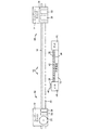
図1および図2は、付加製造装置用の融合システムの1つの例を示す、それぞれ立面図および平面図である。 1 and 2 are an elevation view and a plan view, respectively, showing one example of a fusion system for additive manufacturing equipment.
図3から図26は、図1および図2の融合システムを使用する4パス融合サイクルの1つの例を示す一連の図である。 FIGS. 3 through 26 are a series of diagrams illustrating one example of a 4-pass fusion cycle using the fusion system of FIGS. 1 and 2.
図27は、図1および図2の融合システムで実施されてよいような、付加製造のためのプロセスの1つの例を示す流れ図である。 FIG. 27 is a flow chart showing one example of a process for additive manufacturing, such as may be implemented in the fusion system of FIGS. 1 and 2.
図28は、3Dオブジェクトの付加製造に際してオブジェクトのスライスを形成するのを助ける命令を備えた、プロセッサ可読媒体の1つの例を示すブロック図である。 FIG. 28 is a block diagram illustrating one example of a processor-readable medium with instructions that help form slices of an object during additive manufacturing of a 3D object.
図29は、3Dオブジェクトの付加製造に際してオブジェクトのスライスを形成するのを助ける命令を備えたコントローラを実施する付加製造装置の1つの例を示すブロック図である。 FIG. 29 is a block diagram illustrating one example of an additive manufacturing apparatus that implements a controller with instructions that help form slices of an object during additive manufacturing of a 3D object.
同じ参照番号は、図面全体を通して同じかまたは類似の部材を指定する。図面は縮尺通りではない。 The same reference numbers designate the same or similar parts throughout the drawings. The drawings are not to scale.
幾つかの付加製造プロセスにおいては、粉末状の構築材料中の粒子を相互に融合させるために熱が用いられ、固体のオブジェクトが形成される。構築材料を融合させるための熱は、例えば、液体状の融合剤を粉末状の構築材料の薄い層に対して、オブジェクトのスライスに基づいたパターンで適用し、次いでパターン化された領域を融合光に曝露することによって発生されてよい。融合剤中の光吸収性成分は光エネルギーを吸収し、構築材料を焼結させ、溶融し、またはその他によって融合させるのを助ける。この過程は層ごとおよびスライスごとに繰り返され、オブジェクトが完成される。 In some additive manufacturing processes, heat is used to fuse particles in a powdered build material together to form a solid object. The heat for fusing the build material is applied, for example, by applying a liquid fusing agent to a thin layer of powdered build material in a pattern based on the slices of the object and then fusing the patterned areas. May be generated by exposure to. The light absorbing component in the fusing agent absorbs light energy and helps to sinter, melt, or otherwise fuse the build material. This process is repeated layer by layer and slice by slice to complete the object.
オブジェクトのスライスの各々を速く形成するのを助け、かくして全体の製造時間を低減させる一方で、粉体温度を低下させ、冷却を迅速にしケーキングを少なくするための、付加製造のための新たな融合システムが開発された。1つの例では、この融合システムは、同じ移動直線に沿って作業領域上を往復動する2つのキャリッジを含み、かくして作業領域を横切って、一方のキャリッジは他方のキャリッジに追従することができる。「フューザー」キャリッジは、構築材料を作業領域上に積層させる層形成デバイス、積層された構築材料を加熱する加熱ランプ、および構築材料を融合光で照射するための融合ランプを担持している。加熱ランプはフューザーキャリッジ上に、層形成デバイスよりも下流(積層方向において)に配置されている。溶融ランプは加熱ランプより下流に配置されている。「ディスペンサー」キャリッジは、構築材料の各々の層上へと融合剤を分配するための、剤分配器を担持している。 A new fusion for additive manufacturing to help quickly form each of the object's slices, thus reducing overall manufacturing time, while lowering powder temperature, quicker cooling and less caking. The system was developed. In one example, the fusion system includes two carriages reciprocating over the work area along the same straight line of travel, thus allowing one carriage to follow the other carriage across the work area. The "fuser" carriage carries a layer forming device for laminating build material onto a work area, a heating lamp for heating the laminated build material, and a fusion lamp for illuminating the build material with fusion light. The heating lamp is arranged on the fuser carriage downstream (in the stacking direction) of the layer forming device. The melting lamp is arranged downstream of the heating lamp. A "dispenser" carriage carries an agent dispenser for dispensing the coalescing agent onto each layer of build material.
キャリッジが同じ移動直線に沿って動くデュアル(2重)キャリッジ融合システムは、パスの各々において、スルー速度を速くし、機能を重畳させることができるように助ける。例えば1番目のパスにおいて、フューザーキャリッジが作業領域上を移動するに際して、加熱ランプはオン状態であり、層形成デバイスが構築材料の次の層を形成するにつれて、層形成デバイスの前面にある、下側の層/スライスを加熱する。2番目のパスでは、フューザーキャリッジが作業領域上を戻るよう移動するに際して、加熱ランプはオン状態であり、ディスペンサーキャリッジに先立って構築材料の新たな層を加熱するが、ここでディスペンサーキャリッジは作業領域上でフューザーキャリッジに追従して、次のオブジェクトのスライスに基づいたパターンでもって、加熱された構築材料上へと融合剤および/または装飾化剤を分配する。3番目のパスでは、ディスペンサーキャリッジが作業領域上を戻るように移動して構築材料上へと融合剤および/または装飾化剤を分配し、融合ランプがオン状態とされたフューザーキャリッジがこれに続き、パターン化された構築材料を融合光に曝露する。4番目のパスでは、フューザーキャリッジが作業領域上を移動して戻るに際し、融合光はオン状態であり、パターン化された構築材料を融合光に曝露する。この4パスプロセスは、オブジェクトが層ごとに、またスライスごとに製造されるにつれて、後続する構築材料の層のについて繰り返されてよい。 A dual carriage fusion system in which the carriages move along the same straight line of travel helps to increase the slew rate and overlap functionality in each of the passes. For example, in the first pass, as the fuser carriage moves over the work area, the heat lamps are on and at the front of the layer forming device as the layer forming device forms the next layer of build material. Heat side layer/slice. In the second pass, as the fuser carriage moves back over the work area, the heating lamps are on, heating a new layer of build material prior to the dispenser carriage, where the dispenser carriage is Following the fuser carriage above, the coalescing and/or decorating agent is dispensed onto the heated build material in a pattern based on the slice of the next object. In the third pass, the dispenser carriage moves back over the work area to dispense the coalescing agent and/or decorating agent onto the build material, followed by the fuser carriage with the coalescing lamp on. Exposing the patterned build material to fusion light. In the fourth pass, as the fuser carriage moves over the work area and returns, the fusion light is on and exposes the patterned build material to the fusion light. This four pass process may be repeated for subsequent layers of build material as the object is manufactured layer by layer and slice by slice.
以下に説明し図面に示される以下のおよび他の例は、本件特許を例示するが範囲を限定するものではなく、範囲は説明の後に請求の範囲において規定される。 The following and other examples described below and illustrated in the drawings illustrate the present patent, but do not limit the scope, which is defined in the claims following the description.
本願で使用されるところでは:「および/または」は1つまたはより多くの接続されたものを意味し;「融合剤」は構築材料が焼結、溶融、またはその他により融合するようにさせる物質を意味し;「装飾化剤」は、例えば融合剤の効果を変化させることによって、構築材料の融合を阻止、防止、または向上させる物質を意味し;「光」は任意の波長の電磁放射線を意味し;「ランプ」は光を放射する任意の装置を意味し;そして「作業領域」は融合を行うために構築材料を支持または収容する任意の適切な構造を意味し、これには下側にある構築材料の層および処理中のスライスその他のオブジェクト構造が含まれる。 As used herein: "and/or" means one or more connected; "fusing agent" is a substance that causes the build material to sinter, melt, or otherwise fuse. "Decorating agent" means a substance that prevents, prevents or enhances the fusion of building materials, for example by changing the effect of the fusing agent; "light" refers to electromagnetic radiation of any wavelength. By "lamp" is meant any device that emits light; and by "working area" is meant any suitable structure that supports or contains construction material to effect fusion, which includes the underside. Layers of build material and slices and other object structures being processed.
図1および図2は付加製造装置用の融合システム10の1つの例を示す、それぞれ立面図および平面図である。図3から図26は、システム10を使用する4パス融合サイクルの1つの例を示す一連の図を提示している。まず図1および図2を参照すると、融合システム10は第1の「フューザー」キャリッジ12および第2の「ディスペンサー」キャリッジ14を含んでいる。キャリッジ12および14は、移動直線20に沿って作業領域18の上側を、例えばレール16上で往復動する。フューザーキャリッジ12は、層形成デバイス22、ヒーター24、および融合ランプ26を担持している。ディスペンサーキャリッジ14は、インクジェットプリントヘッドアセンブリまたは他の適切な流体分配アセンブリ28を担持しており、流体融合剤を分配する。図示の例では、分配アセンブリ28、融合剤を分配する第1のディスペンサー30と、装飾化剤を分配する第2のディスペンサー32とを含んでいる。
1 and 2 are an elevational view and a plan view, respectively, showing one example of a
図1および図2に示された例では、層形成デバイス22はローラー22として実施されており、キャリッジ12が作業領域18の上側を移動して構築材料を層に形成する展開位置(図3に示す)と、キャリッジ12が作業領域18の上側を移動するに際して構築材料を層に形成しない後退位置(図1に示す)の間を移動する。層形成ローラー22は作業領域18上を移動するに際して自由に回転し、移動方向に応じて時計回りまたは反時計回りに惰性回転してよく、またはローラー22はいずれかの方向に回転駆動されてよい(同方向回転または反対方向回転)。層形成デバイス22については他の実施形態も可能であり、例えば、ブレード、または作業領域上に構築材料を直接層状に分配する装置などが含まれる。
In the example shown in FIGS. 1 and 2, the
ヒーター24は、例えば加熱ランプ24として実施されてよい。単一の加熱ランプ24が図示されているが、例えばより融通性のある加熱を可能にするために、複数の加熱ランプを使用してよい。同様にして、単一の融合ランプ26が図示されているが、例えば融合光の範囲をより大きくできるように、複数の融合ランプを使用してよい。加熱ランプ24および融合ランプ26の性能は、構築材料の特性や融合剤の特性(および他の処理パラメータ)に応じて変化してよいが、より色温度の低い加熱ランプ24およびより色温度の高い融合ランプ26が、未処理の構築材料および処理済みの構築材料のそれぞれのスペクトル吸収により良好に適合するために、通常は望ましいと考えられる。例えば、白色粉体のポリアミド構築材料38およびブラックの液体融合剤については、未処理の構築材料粉体を予備加熱するために1800°Kの加熱ランプ24が使用されてよく、そして融合剤で処理された構築材料に大きなパワーを伝達し、未処理の粉体により小さなパワーを伝達するために、2750°Kの融合ランプが使用される。
The
上記したように、作業領域18は融合を行うために構築材料を支持または収容する任意の適切な構造を表し、これには下側にある構築材料の層および処理中のスライスその他のオブジェクト構造が含まれる。構築材料の最初の層については、例えば、作業領域18は、層形成プロセスに対処するために上下に移動するプラットフォーム34の表面上に形成されてよい。構築材料の後続の層については、例えば図1に示されているように、作業領域18は下側にあるオブジェクト構造36上に形成されてよく、この構造には、未融合の構築材料38、および融合されてオブジェクトのスライス40となっている構築材料が含まれてよい。
As noted above,
図1および図2においては、フューザーキャリッジ12は作業領域18の片側(図1および図2で左側)に停まっており、そしてディスペンサーキャリッジ14は作業領域18の反対側44(図1および図2で右側)に停まっている。この例においては、構築材料粉体38がリボン46状に、作業領域18に隣接する左側のデッキ48に沿って堆積されている。図3および図4においては、層形成ローラー22が展開され、加熱ランプ24がターンオンされてリボン46にある粉体を加熱し、そして移動矢印50によって示されるように、フューザーキャリッジ12が1番目のパスで右側へと動かされている。図5および図6においては、フューザーキャリッジ12は1番目のパスの右側への移動を継続し、加熱ランプ24は下側にある構築材料36を加熱し、その一方でローラー22は下側にある構造36の上側に構築材料38を層形成する。図面において粉体構築材料38は点描によって示されているが、任意の適切な構築材料を使用してよい。
1 and 2,
図7および図8においては、フューザーキャリッジ12は作業領域18の右側に到達しており、下側にある構造36は層52で覆われた後である。図7および図8に示された例では、層形成ローラー22は後退されていて右側のデッキ55上にある過剰な構築材料38のストリップ54を飛び越え、2番目のパスにおいて過剰な構築材料を再度層形成するのに備えるようになっている。図9から図10および図11から図12においては、移動矢印56によって示されるようにして、フューザーキャリッジ12が2番目のパスにおいて左へと移動するに際して、層形成ローラー22は展開されて、過剰な構築材料を層52へと再度層形成し、そして加熱ランプ24がターンオンされて、層52にある構築材料38を加熱する。やはり2番目のパスにおいて、ディスペンサーキャリッジ14上のディスペンサー30はフューザーキャリッジ12に追従して、所望とするオブジェクトのスライスに対応するパターン60でもって、層52にある構築材料38上へと融合剤58を分配する。
In FIGS. 7 and 8, the
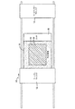
図13および図14においては、フューザーキャリッジ12およびディスペンサーキャリッジ14は、層52にある構築材料38を融合剤58でパターン化した後に、作業領域18の左側に到達している。図15から図16および図17から図18においては、移動矢印62によって示されるようにして、ディスペンサーキャリッジ14が3番目のパスにおいて右へと移動するに際して、ディスペンサー32が装飾化剤64を層52の構築材料38上へと分配する。やはり3番目のパスにおいて、融合ランプ26がターンオンされて、パターン化された構築材料60を融合光で照射するようにされ、パターン化された構築材料は融合されまたは融合を開始されて、オブジェクトのスライス66となる。
13 and 14,
図19および図20においては、フューザーキャリッジ12およびディスペンサーキャリッジ14は、構築材料層52にスライス66を形成した後に、作業領域18の右側へと到達している。図21および図22においては、ディスペンサーキャリッジ14は停まったままであるが、フューザーキャリッジ12は、移動矢印68によって示されているように4番目のパスで左へと移動しており、融合ランプ26がターンオンされて、スライス66を含めてパターン化された構築材料60を照射している。3番目のパス(図17および図18に示す)における融合の程度に応じて、4番目のパスで適用される融合光は、図19および図20に示されているスライス66を完成させてもよく、または例えば1番目(次)のパスに先立って融合ランプ26をターンオンし、図25において示されているようにより多くの融合光でスライス66を照射して、スライス66の完成に向けてパターン化された構築材料60のさらなる融合を行ってもよい。
19 and 20,
図23および図24においては、フューザーキャリッジ12は4番目のパスの後に作業領域18の左側に停まっており、ディスペンサーキャリッジ14は依然として作業領域18の右側に停まっており、そして構築材料のリボン46がデッキ48上に分配されて、作業領域18の上側に構築材料の次の層を形成するのに備えている。図25および図26においては、フューザーキャリッジ12が右へと移動するに際し、融合ランプ26がターンオンされてスライス66を融合光で照射し、加熱ランプ24がターンオンされて新たな下側オブジェクト構造72を加熱する一方で、ローラー22が次の層74の構築材料38を下側構造72の上側に層形成するようになっている。
In FIGS. 23 and 24, the
これらの動作シーケンスは、構築材料の後続層の各々について、スライスごとに継続されてよく、オブジェクトが完成される。 These motion sequences may be continued slice by slice for each subsequent layer of build material to complete the object.
他の処理構成およびシステム構成も可能である。例えば、UV(紫外線)融合ランプ26がUV硬化性融合剤58と共に使用されて構築材料38が融合される場合、加熱ランプ24は省略してもよい。別の例では、層形成ローラー22は、構築材料の再度の層形成が望ましくない場合、および/または粉末構築材料からの浮遊ダストによる汚染からディスペンサー30、32を保護するのを助ける場合、2番目のパス(図9および図10)の間中ずっと後退させたままでよい。より多くのまたはより少ない剤を分配するために、より多くのまたはより少ない剤ディスペンサーを備えることができる。さらに、融合剤および装飾化剤を分配するための順序は、図示したものと異なっていてもよい。
Other processing and system configurations are possible. For example, if
図27は、図1および図2に示された融合システム10で実施されてよいような、付加製造のためのプロセス100の1つの例を示している。図27を参照すると、1番目のキャリッジパスにおいて、処理中のオブジェクト構造が照射され、次いで構築材料の層が、例えば図3から図6を参照して上述したようにして、オブジェクト構造の上側に形成される(ブロック102)。2番目のキャリッジパスでは、層の構築材料が照射され、次いで融合剤および/または装飾化剤が、例えば図9から図12を参照して上述したようにして、層の構築材料上へと分配される(ブロック104)。3番目のキャリッジパスでは、融合剤および/または装飾化剤が層の構築材料上へと分配され、次いで層の構築材料が、例えば図15から図18を参照して上述したようにして照射される(ブロック106)。4番目のキャリッジパスでは、層の構築材料が、例えば図21および図22を参照して上述したようにして照射される(ブロック108)。
FIG. 27 illustrates one example of a
図28は、3Dオブジェクトの製造に際してオブジェクトのスライスを形成するのを助ける命令78を備えた、プロセッサ可読媒体76を示すブロック図である。
FIG. 28 is a block diagram illustrating a processor-
1つの例において、スライス形成命令78は:
例えば図25および図26を参照して上述したように、作業領域上の1番目のパスにおいて、融合剤で処理された構築材料の第1の層の構築材料へと融合エネルギーを適用し、次いで構築材料の第1の層の未処理の構築材料を加熱し、そして次いで構築材料の第1の層を構築材料の第2の層で覆い;
例えば図9から図12を参照して上述したように、作業領域上の2番目のパスにおいて、第2の層の構築材料を加熱し、そして次いで第2の層の加熱された構築材料を融合剤および/または装飾化剤で処理し;
例えば図15から図18を参照して上述したように、作業領域上の3番目のパスにおいて、第2の層の構築材料を融合剤および/または装飾化剤で処理し、そして次いで第2の層の処理された構築材料に融合エネルギーを適用し;そして次に
例えば図21および図22を参照して上述したように、作業領域上の4番目のパスにおいて、第2の層の処理された構築材料に融合エネルギーを適用する命令を含んでいる。
In one example, the
In the first pass over the work area, for example, as described above with reference to FIGS. 25 and 26, fusion energy is applied to the build material of the first layer of build material treated with the fusogenic agent, and then Heating the untreated build material of the first layer of build material, and then covering the first layer of build material with a second layer of build material;
In a second pass over the work area, the second layer build material is heated and then the second layer heated build material is fused, as described above with reference to, for example, FIGS. 9-12. Treated with agents and/or decorating agents;
In a third pass over the work area, for example, as described above with reference to FIGS. 15-18, the build material of the second layer is treated with a fusing agent and/or a decorating agent, and then a second pass. Applying a fusion energy to the treated build material of the layer; and then in a fourth pass over the work area, as described above, eg, with reference to FIGS. 21 and 22, the treated second layer of the second layer. Includes instructions to apply fusion energy to the building material.
別の例においては、図28のスライス形成命令78は、図27に示されたプロセスを実行するための命令を含んでいる。
In another example, the
スライス形成命令78を備えたプロセッサ可読媒体76は、例えば、CADコンピュータプログラム製品中で、オブジェクトモデルプロセッサ中で、または付加製造装置のためのコントローラ中で、実施されてよい。図1から図26に示されたような4パスシーケンスにおいてスライスを形成するための制御データは、例えばソースアプリケーション、通常はCADコンピュータプログラム製品上のプロセッサ可読媒体によって、オブジェクトモデルプロセッサ中において、または付加製造装置上のプロセッサ可読命令によって、生成されてよい。
Processor readable medium 76 with
図29は、スライス形成命令78を備えたコントローラ82を実施する付加製造装置80の1つの例を示すブロック図である。図29を参照すると、装置80は、コントローラ82、作業領域18、構築材料層形成デバイス84、融合剤ディスペンサー30、装飾化剤ディスペンサー32、ヒーター24、および融合ランプ26を含んでいる。構築材料層形成デバイス84は、作業領域18の上側に構築材料の層を形成し、そして例えば、構築材料を分配する装置と、層の各々について構築材料を拡げるためのブレードまたはローラー22を含んでよい。融合剤ディスペンサー30および装飾化剤ディスペンサー32は、例えば図11から図12および図15から図16を参照して上述したようにして、コントローラ82の指示のもとに、それぞれの剤を選択的に分配する。任意の適切なディスペンサー30、32を使用してよいが、剤を分配可能な精密さ、および異なる種類および配合処方の剤を分配する融通性の故に、付加製造装置においてはインクジェットプリントヘッドが場合によって使用されてよい。
FIG. 29 is a block diagram showing an example of an
コントローラ82は、プロセッサ(または複数のプロセッサ)、関連するメモリ(または複数のメモリ)および命令、ならびに装置80の作動要素を制御するのに必要な電子回路および部品を表している。特に、コントローラ82は、スライス形成命令78を備えたプロセッサ可読媒体76、および命令78を読み出して実行するプロセッサ86を含んでいる。
図面に示された上述の例は、本件特許を例示するものであるが限定するものではなく、特許は以下の請求の範囲に規定されている。 The above examples shown in the drawings illustrate, but are not limited to, the present patent, which is defined by the following claims.
請求の範囲において使用される「ある」、「1つの」および「その」は、少なくとも1つを意味している。例えば「ある融合ランプ」は1つまたはより多くの融合ランプを意味し、その後の「その融合ランプ」という言及は、その1つまたはより多くの融合ランプを意味している。 As used in the claims, "a", "an" and "the" mean at least one. For example, "a fusion lamp" means one or more fusion lamps, and subsequent references to "the fusion lamp" mean one or more fusion lamps.
Claims (15)
層形成デバイス、加熱ランプ、および融合ランプを担持する第1のキャリッジであって、移動直線に沿って作業領域上を第1の方向および第1の方向と反対の第2の方向において往復動可能な第1のキャリッジと;
剤分配器を担持する第2のキャリッジであって、移動直線に沿って作業領域上を第1の方向および第2の方向において往復動可能な第2のキャリッジと;
第1のキャリッジ、加熱ランプ、融合ランプ、第2のキャリッジ、および剤分配器に関連して作動するよう接続されたコントローラであって:
1番目のパスにおいて第1のキャリッジを作業領域上で第1の方向に移動させている間に、オブジェクト構造上に構築材料を層形成して構築材料層を形成し;
2番目のパスにおいて第1のキャリッジおよび第2のキャリッジを作業領域上で第2の方向に移動させている間に、層の構築材料を加熱ランプで照射し、次いで剤分配器で融合剤および/または装飾化剤を層の構築材料上に分配し;
3番目のパスにおいて第2のキャリッジおよび第1のキャリッジを作業領域上で第1の方向に移動させている間に、剤分配器で融合剤および/または装飾化剤を層の構築材料上に分配し、次いで層の構築材料を融合ランプで照射し;そして
4番目のパスにおいて、第1のキャリッジを作業領域上で第2の方向に戻るよう移動させている間に、層の構築材料を融合ランプで照射するコントローラとを含む、システム。 An integrated system for add-on manufacturing equipment:
A first carriage carrying a layer forming device, a heating lamp and a fusion lamp, which is reciprocable in a first direction and in a second direction opposite to the first direction along a straight line of movement. A first carriage;
A second carriage for carrying the agent distributor, the second carriage being capable of reciprocating in a first direction and a second direction on a work area along a moving straight line;
A controller connected to operate in connection with the first carriage, the heating lamp, the fusion lamp, the second carriage, and the agent dispenser:
Forming a build material layer by layering build material on the object structure while moving the first carriage in the first direction over the work area in a first pass;
In the second pass, while moving the first carriage and the second carriage in the second direction over the work area, the build material of the layer is irradiated with a heating lamp, and then the fusion agent and And/or distributing the decorating agent on the building material of the layer;
In the third pass, while moving the second carriage and the first carriage in the first direction over the work area, the coalescing agent and/or the decorating agent is applied on the building material of the layer by the agent distributor. Dispense and then illuminate the layer build material with a fusion lamp; and in a fourth pass, while the first carriage is moving back on the work area in a second direction, the layer build material is A system including a controller for illuminating with a fusion lamp.
作業領域上に構築材料の層を形成する層形成デバイスおよび作業領域にある構築材料を融合光で照射する融合ランプを担持する第1のキャリッジであって、融合ランプが第1のキャリッジ上に、第1の方向において層形成デバイスよりも下流に配置されている第1のキャリッジと;
融合剤を分配する剤分配器を担持する第2のキャリッジとを含み;そして
第1のキャリッジおよび第2のキャリッジは同じ移動直線に沿って作業領域上を往復動可能であり、第1のキャリッジは第1の方向において第2のキャリッジに追従し、第2のキャリッジは第1の方向と反対の第2の方向において第1のキャリッジに追従する、システム。 An integrated system for add-on manufacturing equipment:
A first carriage carrying a layering device for forming a layer of build material on a work area and a fusion lamp for illuminating the build material in the work area with fusion light , the fusion lamp on the first carriage, A first carriage arranged downstream of the layer forming device in a first direction ;
A second carriage carrying an agent dispenser for dispensing the fusion agent; and the first carriage and the second carriage are reciprocable on the work area along the same straight line of travel, the first carriage System follows a second carriage in a first direction, the second carriage follows a first carriage in a second direction opposite the first direction.
第2のキャリッジは作業領域の他方の側に停止可能であり、第1のキャリッジが第2のキャリッジに先導または追従することなく作業領域上を往復どうすることを許容する、請求項6のシステム。 The first carriage can be stopped on one side of the work area, allowing the second carriage to reciprocate on the work area without leading or following the first carriage; and the second carriage 7. The system of claim 6, which is stoppable on the other side of the area to allow the first carriage to shuttle back and forth over the work area without leading or following the second carriage.
1番目のキャリッジパスにおいて、オブジェクト構造の上側に構築材料を層形成させて構築材料の層を形成し;
2番目のキャリッジパスにおいて、層の構築材料を照射させ、次いで層の構築材料上に融合剤および/または装飾化剤を分配させ;
3番目のキャリッジパスにおいて、層の構築材料上に融合剤および/または装飾化剤を分配させ、次いで層の構築材料を照射させ;そして
4番目のキャリッジパスにおいて、層の構築材料を照射させる命令が書き込まれている、プロセッサ可読媒体。 A processor readable medium for an integrated system for an additive manufacturing device when executed:
In the first carriage pass, build material is layered on top of the object structure to form a layer of build material;
In a second carriage pass, the layer build material is irradiated and then the coalescing and/or decorating agent is distributed on the layer build material;
In a third carriage pass, the coalescing and/or decorating agent is dispensed onto the build material of the layer and then the build material of the layer is irradiated; and in the fourth carriage pass, the build material of the layer is irradiated. It is that has been written, the processor-readable medium.
3番目のパスにおいて構築材料を照射する命令は、構築材料を融合ランプで照射する命令を含み;そして
4番目のパスにおいて構築材料を照射する命令は、構築材料を融合ランプで照射する命令を含む、請求項11または12のプロセッサ可読媒体。 The instructions to illuminate the build material in the second pass include instructions to illuminate the build material with a heating lamp;
The instruction to illuminate the build material in the third pass includes an instruction to illuminate the build material with the fusion lamp; and the instruction to illuminate the build material in the fourth pass includes an instruction to illuminate the build material with the fusion lamp. 13. The processor-readable medium of claim 11 or 12 .
Applications Claiming Priority (1)
| Application Number | Priority Date | Filing Date | Title |
|---|---|---|---|
| PCT/US2016/057730 WO2018075033A1 (en) | 2016-10-19 | 2016-10-19 | Additive manufacturing |
Publications (2)
| Publication Number | Publication Date |
|---|---|
| JP2019524517A JP2019524517A (en) | 2019-09-05 |
| JP6736773B2 true JP6736773B2 (en) | 2020-08-05 |
Family
ID=62018983
Family Applications (2)
| Application Number | Title | Priority Date | Filing Date |
|---|---|---|---|
| JP2019528017A Active JP6736773B2 (en) | 2016-10-19 | 2016-10-19 | Additive manufacturing |
| JP2019509531A Active JP6808816B2 (en) | 2016-10-19 | 2017-01-31 | Lamination of modeling material particles |
Family Applications After (1)
| Application Number | Title | Priority Date | Filing Date |
|---|---|---|---|
| JP2019509531A Active JP6808816B2 (en) | 2016-10-19 | 2017-01-31 | Lamination of modeling material particles |
Country Status (7)
| Country | Link |
|---|---|
| US (3) | US10981331B2 (en) |
| EP (2) | EP3487681A4 (en) |
| JP (2) | JP6736773B2 (en) |
| KR (2) | KR102204486B1 (en) |
| CN (2) | CN109562564B (en) |
| BR (2) | BR112019003589A2 (en) |
| WO (2) | WO2018075033A1 (en) |
Families Citing this family (14)
| Publication number | Priority date | Publication date | Assignee | Title |
|---|---|---|---|---|
| US10967566B2 (en) | 2015-10-30 | 2021-04-06 | Seurat Technologies, Inc. | Chamber systems for additive manufacturing |
| EP3612370A4 (en) * | 2017-04-21 | 2020-11-18 | Hewlett-Packard Development Company, L.P. | Carriage synchronization |
| US11305487B2 (en) * | 2017-04-21 | 2022-04-19 | Hewlett-Packard Development Company, L.P. | Additive manufacturing roller within radiative heat transfer area |
| US11712843B2 (en) * | 2017-12-07 | 2023-08-01 | General Electric Company | Binder jetting apparatus and methods |
| US11225022B2 (en) | 2018-01-25 | 2022-01-18 | Hewlett-Packard Development Company, L.P. | Build material dispensing device |
| WO2019203856A1 (en) * | 2018-04-20 | 2019-10-24 | Desktop Metal, Inc. | Spreader positioning in multi-directional binder jetting for additive manufacturing |
| CN110757790A (en) * | 2018-07-27 | 2020-02-07 | 三纬国际立体列印科技股份有限公司 | 3D laser printing device and operation method thereof |
| US11383434B2 (en) * | 2018-07-31 | 2022-07-12 | Hewlett-Packard Development Company, L.P. | Fusing three-dimensional (3D) object layers |
| GB2579639A (en) * | 2018-12-07 | 2020-07-01 | Xaar 3D Ltd | Sled configurations and methods of operation for the manufacture of three-dimensional objects |
| GB2579638B (en) * | 2018-12-07 | 2021-10-27 | Xaar 3D Ltd | Methods and apparatus for the manufacture of three-dimensional objects |
| US20220314541A1 (en) * | 2019-05-23 | 2022-10-06 | General Electric Company | Actuator assemblies for additive manufacturing apparatuses and methods for using the same |
| WO2021066824A1 (en) * | 2019-10-02 | 2021-04-08 | Hewlett-Packard Development Company, L.P. | Independently movable carriages carrying respective energy sources |
| WO2021150248A1 (en) * | 2020-01-24 | 2021-07-29 | Hewlett-Packard Development Company, L.P. | Energy source setting |
| JP2023042934A (en) * | 2021-09-15 | 2023-03-28 | 新東工業株式会社 | Test system and test method |
Family Cites Families (44)
| Publication number | Priority date | Publication date | Assignee | Title |
|---|---|---|---|---|
| US5387380A (en) * | 1989-12-08 | 1995-02-07 | Massachusetts Institute Of Technology | Three-dimensional printing techniques |
| US6504127B1 (en) * | 1999-09-30 | 2003-01-07 | National Research Council Of Canada | Laser consolidation methodology and apparatus for manufacturing precise structures |
| US6896839B2 (en) | 2001-02-07 | 2005-05-24 | Minolta Co., Ltd. | Three-dimensional molding apparatus and three-dimensional molding method |
| US20020149137A1 (en) * | 2001-04-12 | 2002-10-17 | Bor Zeng Jang | Layer manufacturing method and apparatus using full-area curing |
| US6986654B2 (en) | 2002-07-03 | 2006-01-17 | Therics, Inc. | Apparatus, systems and methods for use in three-dimensional printing |
| EP1396556A1 (en) * | 2002-09-06 | 2004-03-10 | ALSTOM (Switzerland) Ltd | Method for controlling the microstructure of a laser metal formed hard layer |
| JP4299157B2 (en) * | 2004-02-03 | 2009-07-22 | トヨタ自動車株式会社 | Powder metal overlay nozzle |
| US7389154B2 (en) | 2004-09-29 | 2008-06-17 | Hewlett-Packard Development Company, L.P. | Fabricating a three-dimensional object |
| KR100606457B1 (en) * | 2004-11-11 | 2006-11-23 | 한국기계연구원 | Three-dimensional printing prototyping system |
| DE102005022308B4 (en) * | 2005-05-13 | 2007-03-22 | Eos Gmbh Electro Optical Systems | Apparatus and method for manufacturing a three-dimensional object with a heated powder coating material build-up material |
| EP1759791A1 (en) | 2005-09-05 | 2007-03-07 | Nederlandse Organisatie voor toegepast- natuurwetenschappelijk onderzoek TNO | Apparatus and method for building a three-dimensional article |
| JP4693681B2 (en) * | 2006-03-31 | 2011-06-01 | パナソニック株式会社 | Manufacturing method of stereolithography |
| EP2001656B1 (en) * | 2006-04-06 | 2014-10-15 | 3D Systems Incorporated | KiT FOR THE PRODUCTION OF THREE-DIMENSIONAL OBJECTS BY USE OF ELECTROMAGNETIC RADIATION |
| JP5400042B2 (en) * | 2008-05-26 | 2014-01-29 | ソニー株式会社 | Modeling equipment |
| US8545209B2 (en) * | 2009-03-31 | 2013-10-01 | Microjet Technology Co., Ltd. | Three-dimensional object forming apparatus and method for forming three-dimensional object |
| JP5663231B2 (en) * | 2009-08-07 | 2015-02-04 | 株式会社半導体エネルギー研究所 | Light emitting device |
| JP5759850B2 (en) * | 2011-09-22 | 2015-08-05 | 株式会社キーエンス | 3D modeling equipment |
| FR2998496B1 (en) | 2012-11-27 | 2021-01-29 | Association Pour La Rech Et Le Developpement De Methodes Et Processus Industriels Armines | ADDITIVE MANUFACTURING PROCESS OF A PART BY SELECTIVE FUSION OR SELECTIVE SINTING OF BEDS OF POWDER WITH COMPACITY OPTIMIZED BY A HIGH ENERGY BEAM |
| EP2862652A1 (en) | 2013-10-15 | 2015-04-22 | Siemens Aktiengesellschaft | Electron beam melting method and electron beam apparatus |
| IL294425B2 (en) * | 2013-10-17 | 2023-09-01 | Xjet Ltd | Support ink for three dimensional (3d) printing |
| US10434572B2 (en) | 2013-12-19 | 2019-10-08 | Arcam Ab | Method for additive manufacturing |
| FR3014339B1 (en) * | 2013-12-06 | 2016-01-08 | Snecma | PROCESS FOR MANUFACTURING A PIECE BY SELECTIVE FUSION OF POWDER |
| US10130993B2 (en) | 2013-12-18 | 2018-11-20 | Arcam Ab | Additive manufacturing of three-dimensional articles |
| DE102013021891A1 (en) * | 2013-12-23 | 2015-06-25 | Voxeljet Ag | Apparatus and method with accelerated process control for 3D printing processes |
| WO2015108544A1 (en) * | 2014-01-16 | 2015-07-23 | Hewlett-Packard Development Company, L.P. | Polymeric powder composition for three-dimensional (3d) printing |
| GB2538409B (en) * | 2014-01-16 | 2020-02-26 | Hewlett Packard Development Co | Generating three-dimensional objects |
| WO2015106838A1 (en) * | 2014-01-16 | 2015-07-23 | Hewlett-Packard Development Company, L.P. | Generating a three-dimensional object |
| US10647059B2 (en) | 2014-01-16 | 2020-05-12 | Hewlett-Packard Development Company, L.P. | Generating a three-dimensional object |
| US10583612B2 (en) * | 2014-01-16 | 2020-03-10 | Hewlett-Packard Development Company, L.P. | Three-dimensional (3D) printing method |
| JP2015164770A (en) * | 2014-03-03 | 2015-09-17 | セイコーエプソン株式会社 | Apparatus for manufacturing three-dimensional molded article, method for manufacturing three-dimensional molded article, and three-dimensional molded article |
| JP2015174338A (en) * | 2014-03-14 | 2015-10-05 | セイコーエプソン株式会社 | Three-dimensional shaped object production apparatus, three-dimensional shaped object production method, and three-dimensional shaped object |
| US20150306667A1 (en) | 2014-04-24 | 2015-10-29 | Shi-Chune Yao | Utilization of Partial Sintering to Avoid the Use of Support Structures in the Direct Metal Laser Sintering Additive Manufacturing Processes |
| KR102180185B1 (en) * | 2014-04-30 | 2020-11-18 | 휴렛-팩커드 디벨롭먼트 컴퍼니, 엘.피. | Computational model and three-dimensional (3d) printing methods |
| CN204036858U (en) | 2014-08-19 | 2014-12-24 | 珠海天威飞马打印耗材有限公司 | Color three-dimensional printer |
| BR112017006487A2 (en) * | 2014-09-30 | 2018-07-03 | Hewlett Packard Development Co | generation of a three dimensional object |
| JP2016078405A (en) | 2014-10-22 | 2016-05-16 | セイコーエプソン株式会社 | Method for manufacturing three-dimensional molded article, apparatus for manufacturing three-dimensional molded article, and three-dimensional molded article |
| EP3221125B1 (en) | 2014-11-20 | 2019-08-28 | Hewlett-Packard Development Company, L.P. | Generating three-dimensional objects |
| GB2532518A (en) * | 2014-11-24 | 2016-05-25 | Digital Metal Ab | Manufacturing method and manufacturing apparatus |
| DE102015006533A1 (en) | 2014-12-22 | 2016-06-23 | Voxeljet Ag | Method and device for producing 3D molded parts with layer construction technique |
| CN107107471B (en) * | 2015-01-14 | 2021-01-15 | 惠普发展公司有限责任合伙企业 | Additive manufacturing |
| JP6460554B2 (en) * | 2015-01-30 | 2019-01-30 | ヒューレット−パッカード デベロップメント カンパニー エル.ピー.Hewlett‐Packard Development Company, L.P. | 3D object generation |
| JP2016168704A (en) * | 2015-03-12 | 2016-09-23 | セイコーエプソン株式会社 | Three-dimensional molding apparatus, production method, and computer program |
| CN205326292U (en) | 2015-12-23 | 2016-06-22 | 中山市众望电子科技有限公司 | Novel 3D printer removes guiding mechanism |
| CN105711098B (en) * | 2016-03-24 | 2018-11-02 | 广东劲胜智能集团股份有限公司 | A kind of plastics 3D printing method and product |
-
2016
- 2016-10-19 BR BR112019003589-3A patent/BR112019003589A2/en active Search and Examination
- 2016-10-19 EP EP16919188.9A patent/EP3487681A4/en active Pending
- 2016-10-19 KR KR1020197004629A patent/KR102204486B1/en active IP Right Grant
- 2016-10-19 CN CN201680088325.7A patent/CN109562564B/en active Active
- 2016-10-19 JP JP2019528017A patent/JP6736773B2/en active Active
- 2016-10-19 US US16/075,430 patent/US10981331B2/en active Active
- 2016-10-19 WO PCT/US2016/057730 patent/WO2018075033A1/en unknown
-
2017
- 2017-01-31 EP EP17862164.5A patent/EP3487683B1/en active Active
- 2017-01-31 CN CN201780050093.0A patent/CN109562569B/en active Active
- 2017-01-31 KR KR1020197004439A patent/KR102223986B1/en active IP Right Grant
- 2017-01-31 BR BR112019003681-4A patent/BR112019003681A2/en active Search and Examination
- 2017-01-31 WO PCT/US2017/015859 patent/WO2018075087A1/en unknown
- 2017-01-31 US US16/074,319 patent/US11760016B2/en active Active
- 2017-01-31 JP JP2019509531A patent/JP6808816B2/en active Active
-
2021
- 2021-03-12 US US17/200,406 patent/US11654626B2/en active Active
Also Published As
| Publication number | Publication date |
|---|---|
| CN109562569B (en) | 2022-03-18 |
| CN109562564B (en) | 2021-07-23 |
| US20190039303A1 (en) | 2019-02-07 |
| EP3487683B1 (en) | 2022-05-04 |
| US11654626B2 (en) | 2023-05-23 |
| WO2018075033A1 (en) | 2018-04-26 |
| EP3487681A4 (en) | 2020-04-22 |
| US11760016B2 (en) | 2023-09-19 |
| JP2019524508A (en) | 2019-09-05 |
| US10981331B2 (en) | 2021-04-20 |
| EP3487683A1 (en) | 2019-05-29 |
| US20210197461A1 (en) | 2021-07-01 |
| KR102223986B1 (en) | 2021-03-08 |
| BR112019003681A2 (en) | 2019-05-21 |
| KR20190029694A (en) | 2019-03-20 |
| BR112019003589A2 (en) | 2019-05-21 |
| US20210187835A1 (en) | 2021-06-24 |
| CN109562569A (en) | 2019-04-02 |
| EP3487681A1 (en) | 2019-05-29 |
| KR20190029675A (en) | 2019-03-20 |
| KR102204486B1 (en) | 2021-01-18 |
| CN109562564A (en) | 2019-04-02 |
| WO2018075087A1 (en) | 2018-04-26 |
| JP2019524517A (en) | 2019-09-05 |
| JP6808816B2 (en) | 2021-01-06 |
| EP3487683A4 (en) | 2020-03-11 |
Similar Documents
| Publication | Publication Date | Title |
|---|---|---|
| JP6736773B2 (en) | Additive manufacturing | |
| US20220362992A1 (en) | Lighting for additive manufacturing | |
| US20170326791A1 (en) | Consolidating a build material for additive manufacturing | |
| TWI680860B (en) | Lighting for additive manufacturing | |
| US11383434B2 (en) | Fusing three-dimensional (3D) object layers | |
| CN110325345B (en) | Additive manufacturing | |
| WO2017142506A1 (en) | Build material supply for additive manufacturing | |
| WO2017127114A1 (en) | Layering powdered build material for additive manufacturing | |
| US20200353686A1 (en) | Lighting assembly for additive manufacturing | |
| WO2017127113A1 (en) | Layering powdered build material for additive manufacturing | |
| US20210016350A1 (en) | Preheat dyed build materials with preheating sources | |
| CN113518703B (en) | Roller control for 3D printer | |
| WO2022031285A1 (en) | Increasing energy absorption during additive manufacturing |
Legal Events
| Date | Code | Title | Description |
|---|---|---|---|
| A621 | Written request for application examination |
Free format text: JAPANESE INTERMEDIATE CODE: A621 Effective date: 20190206 |
|
| A977 | Report on retrieval |
Free format text: JAPANESE INTERMEDIATE CODE: A971007 Effective date: 20191216 |
|
| A131 | Notification of reasons for refusal |
Free format text: JAPANESE INTERMEDIATE CODE: A131 Effective date: 20200121 |
|
| A521 | Request for written amendment filed |
Free format text: JAPANESE INTERMEDIATE CODE: A523 Effective date: 20200421 |
|
| TRDD | Decision of grant or rejection written | ||
| A01 | Written decision to grant a patent or to grant a registration (utility model) |
Free format text: JAPANESE INTERMEDIATE CODE: A01 Effective date: 20200616 |
|
| A61 | First payment of annual fees (during grant procedure) |
Free format text: JAPANESE INTERMEDIATE CODE: A61 Effective date: 20200715 |
|
| R150 | Certificate of patent or registration of utility model |
Ref document number: 6736773 Country of ref document: JP Free format text: JAPANESE INTERMEDIATE CODE: R150 |
|
| R250 | Receipt of annual fees |
Free format text: JAPANESE INTERMEDIATE CODE: R250 |