JP6735882B2 - Liquid detection unit, compressor and air conditioner - Google Patents
Liquid detection unit, compressor and air conditioner Download PDFInfo
- Publication number
- JP6735882B2 JP6735882B2 JP2019119516A JP2019119516A JP6735882B2 JP 6735882 B2 JP6735882 B2 JP 6735882B2 JP 2019119516 A JP2019119516 A JP 2019119516A JP 2019119516 A JP2019119516 A JP 2019119516A JP 6735882 B2 JP6735882 B2 JP 6735882B2
- Authority
- JP
- Japan
- Prior art keywords
- housing
- liquid
- electrode plates
- compressor
- unit
- Prior art date
- Legal status (The legal status is an assumption and is not a legal conclusion. Google has not performed a legal analysis and makes no representation as to the accuracy of the status listed.)
- Expired - Fee Related
Links
- 238000001514 detection method Methods 0.000 title claims description 197
- 239000007788 liquid Substances 0.000 title claims description 125
- 239000010687 lubricating oil Substances 0.000 claims description 19
- 239000003507 refrigerant Substances 0.000 claims description 19
- 230000002093 peripheral effect Effects 0.000 claims description 17
- 230000006835 compression Effects 0.000 claims description 6
- 238000007906 compression Methods 0.000 claims description 6
- 239000002184 metal Substances 0.000 description 13
- 229910052751 metal Inorganic materials 0.000 description 13
- 238000007789 sealing Methods 0.000 description 13
- 239000012535 impurity Substances 0.000 description 12
- 239000003921 oil Substances 0.000 description 9
- 238000003466 welding Methods 0.000 description 9
- 239000011521 glass Substances 0.000 description 8
- 239000000758 substrate Substances 0.000 description 6
- 239000010935 stainless steel Substances 0.000 description 5
- 229910001220 stainless steel Inorganic materials 0.000 description 5
- 238000001816 cooling Methods 0.000 description 3
- 238000010438 heat treatment Methods 0.000 description 3
- 239000011810 insulating material Substances 0.000 description 3
- WABPQHHGFIMREM-UHFFFAOYSA-N lead(0) Chemical compound [Pb] WABPQHHGFIMREM-UHFFFAOYSA-N 0.000 description 3
- 230000004048 modification Effects 0.000 description 3
- 238000012986 modification Methods 0.000 description 3
- 229910000990 Ni alloy Inorganic materials 0.000 description 2
- 238000005219 brazing Methods 0.000 description 2
- 238000005259 measurement Methods 0.000 description 2
- 239000007769 metal material Substances 0.000 description 2
- 230000000149 penetrating effect Effects 0.000 description 2
- 238000005057 refrigeration Methods 0.000 description 2
- 229920003002 synthetic resin Polymers 0.000 description 2
- 239000000057 synthetic resin Substances 0.000 description 2
- 229930091051 Arenine Natural products 0.000 description 1
- 230000002159 abnormal effect Effects 0.000 description 1
- 239000003990 capacitor Substances 0.000 description 1
- 210000000078 claw Anatomy 0.000 description 1
- 238000011109 contamination Methods 0.000 description 1
- 238000010586 diagram Methods 0.000 description 1
- 230000001050 lubricating effect Effects 0.000 description 1
- 238000005461 lubrication Methods 0.000 description 1
- 239000000463 material Substances 0.000 description 1
- 239000004570 mortar (masonry) Substances 0.000 description 1
- 230000035515 penetration Effects 0.000 description 1
- 229920002379 silicone rubber Polymers 0.000 description 1
- 239000004945 silicone rubber Substances 0.000 description 1
- 239000007787 solid Substances 0.000 description 1
Images


Description
本発明は、例えば、空気調和機に用いられる圧縮機の潤滑油の液面高さの検知などに用いられる静電容量式の液体検知ユニット、この液体検知ユニットを有する圧縮機、及び、この圧縮機を備える空気調和機に関する。 The present invention relates to, for example, a capacitance type liquid detection unit used for detecting the liquid level of lubricating oil of a compressor used in an air conditioner, a compressor having this liquid detection unit, and this compression unit. Air conditioner equipped with a machine.
空気調和機は、室外熱交換器及び室内熱交換器と、これらの間に設けられた膨張弁と圧縮機とを備えている。空気調和機の冷凍サイクルでは、一例として、室外熱交換器を通過した液状の冷媒が、膨張弁でガス状になることにより温度が低下して冷気となり室内熱交換器に導かれる。そして、室内熱交換器により室内の空気に熱(低温)を移したガス状の冷媒は、圧縮機で圧縮されて高温・高圧状態となり、室外熱交換器により室外の空気に熱(高温)を移すことにより再び液状になる。 The air conditioner includes an outdoor heat exchanger and an indoor heat exchanger, and an expansion valve and a compressor provided between them. In the refrigeration cycle of the air conditioner, as an example, the liquid refrigerant that has passed through the outdoor heat exchanger is cooled by the expansion valve into a gaseous state, and the temperature of the liquid refrigerant becomes cold air, which is guided to the indoor heat exchanger. Then, the gaseous refrigerant that has transferred heat (low temperature) to the indoor air by the indoor heat exchanger is compressed by the compressor to a high temperature/high pressure state, and heat (high temperature) is applied to the outdoor air by the outdoor heat exchanger. It becomes liquid again by transferring.
このような空気調和機に用いられる圧縮機として、ロータリー方式やスクロール方式などを採用したものがある。例えば、特許文献1に開示されたロータリー方式の圧縮機は、作動室が形成されたシリンダと当該作動室に収容された環状ピストンとを有する圧縮部がタンク状の圧縮機筐体内に配設されており、この環状ピストンが外周面の一部を作動室の周壁面に当接しながら回転されることにより、作動室内に導入された冷媒の圧縮が行われる。
As a compressor used in such an air conditioner, there is a compressor that adopts a rotary system or a scroll system. For example, in the rotary compressor disclosed in
特許文献1に開示された圧縮機では、シリンダやピストンなどの摺動部品の潤滑及び微小隙間のシール(封止)などのために圧縮機筐体内に潤滑油が収容されている。そして、この潤滑油が何らかの原因により所定量より少なくなると圧縮機の動作に支障をきたすため、潤滑油の量を監視する必要がある。このような潤滑油の量の監視に用いることができるセンサが、例えば、特許文献2に開示されている。
In the compressor disclosed in
図12に示すように、この特許文献2に開示されたセンサ(図中、符号901で示す)は、基板体902に取り付けられた一対の導電ピン904の端部に、互いに間隔をあけて平行に配置された一対の帯状の電極板905が取り付けられている。そして、一対の電極板905の間の潤滑油の有無により導電ピン904間の静電容量が変化するので、このセンサ901を圧縮機筐体内の適切な高さ位置に設けることで、潤滑油の量が所定量以上あるか否かを検知することができる。
As shown in FIG. 12, the sensor disclosed in Patent Document 2 (indicated by
上述した従来のセンサは、一対の電極板の間の潤滑油の有無を静電容量の変化により検出するものであるが、この静電容量は、例えば圧縮機を制御するコントローラの検出回路で検出される。このため、一対の導電ピン904に電線を繋ぎ、上記コントローラに対して電線を介して接続される。しかしながら、上記従来のセンサの構造では、上記電線による静電容量が電極板905による静電容量に結合されるため、電極板905における静電容量に対するバイアスが大きく、コントローラで検知される静電容量のS/N比が悪く、例えば潤滑油等の液体の液面高さの誤検知を生じるという問題がある。
The above-described conventional sensor detects the presence or absence of lubricating oil between a pair of electrode plates based on a change in capacitance. This capacitance is detected by, for example, a detection circuit of a controller that controls a compressor. .. Therefore, an electric wire is connected to the pair of
そこで、本発明は、静電容量を精度良く検出できる静電容量式の液体検知ユニット、この液体検知ユニットを有する圧縮機、及び、この圧縮機を備えた空気調和機を提供することを目的とする。 Therefore, an object of the present invention is to provide an electrostatic capacity type liquid detection unit capable of accurately detecting electrostatic capacity, a compressor having this liquid detection unit, and an air conditioner equipped with this compressor. To do.
請求項1の液体検知ユニットは、複数の電極板の間の静電容量により液体を検知する液体検知ユニットであって、前記電極板が取り付けられた複数の導電端子と、前記導電端子を介して前記電極板の間の静電容量を検知して当該静電容量に応じた検知信号を出力する検知回路と、前記複数の導電端子と前記検知回路を収めることができるユニットケースと、円筒状の周壁部、及び、該周壁部の一端を塞ぐ底壁部を備えたケースと、を有し、前記導電端子と、前記導電端子に電気的に接続された前記検知回路をユニットケースにて一体とし、複数の前記電極板のそれぞれに対し、複数の前記導電端子が、他の前記電極板とは独立に設けられており、前記導電端子は、前記電極板と反対側の端部がオス端子となっており、前記検知回路には、メス端子が接続されており、前記オス端子と前記メス端子とが接触することにより、前記検知回路が前記電極板の間の静電容量を検知し、前記ユニットケースが、前記複数の導電端子を取り付けたベースと、前記検知回路を収容固定したハウジングとで構成され、前記ユニットケースが、前記ベースと前記ハウジングとにより一対のコネクタとして互いに嵌合可能とされ、前記ベースが、前記導電端子が配置される円筒部を有し、前記ハウジングが、前記メス端子が形成された円柱部を有し、前記円柱部が前記円筒部内に収容されることで嵌合するとともに、前記ケースが前記ベースとの間に前記ハウジングを挟み込み、前記円筒部が前記周壁部内に収容されることで嵌合することを特徴とする。
The liquid detection unit according to
参考発明の液体検知ユニットは、複数の電極板の間の静電容量により液体を検知する液体検知ユニットであって、前記電極板が取り付けられた複数の導電端子と、前記導電端子を介して前記電極板の間の静電容量を検知して当該静電容量に応じた検知信号を出力する検知回路と、前記複数の導電端子と前記検知回路を収めることができるユニットケースと、を有し、前記導電端子と、前記導電端子に電気的に接続された前記検知回路をユニットケースにて一体とし、前記ユニットケースが、前記複数の導電端子が取り付けられるとともに前記検知回路を収容固定した第1ケースと、検知対象の液体を収容する筺体及び前記第1ケース間に介在される金属製の第2ケースと、で構成され、前記第1ケース及び前記第2ケースのうちの、一方に雄ねじと円錐台の側面の形状をしたシール面が形成され、他方に雌ねじとすり鉢状のシール面が形成され、前記第1ケースと第2ケースとを前記雄ねじ及び雌ねじで締結することにより、該第1ケースに取り付けられた前記導電端子及び電極板を前記第2ケースの前記筺体内に連通する開口部に挿通するとともに、該第1ケース及び第2ケースの前記両シール面により金属シール構造をとることを特徴とする。 The liquid detection unit of the reference invention is a liquid detection unit that detects a liquid by the electrostatic capacitance between a plurality of electrode plates, and a plurality of conductive terminals to which the electrode plates are attached, and between the electrode plates via the conductive terminals. A detection circuit that detects the electrostatic capacity of the device and outputs a detection signal corresponding to the electrostatic capacity, and a unit case that can accommodate the plurality of conductive terminals and the detection circuit, and the conductive terminal A detection unit electrically connected to the conductive terminals in a unit case, the unit case having the plurality of conductive terminals attached and housing and fixing the detection circuits; and a detection target. And a metal second case interposed between the first case and the housing for storing the liquid, wherein one of the first case and the second case has a male screw and a side surface of the truncated cone. A shaped sealing surface is formed, and a female thread and a mortar-shaped sealing surface are formed on the other side, and the first case and the second case are attached to the first case by fastening them with the male screw and the female screw. The conductive terminal and the electrode plate are inserted into an opening communicating with the housing of the second case, and a metal seal structure is formed by the both sealing surfaces of the first case and the second case.
請求項2の液体検知ユニットは、筐体内に収容された液体の検知に用いられる請求項1に記載の液体検知ユニットであって、前記ユニットケースが、前記筐体の壁部に設けられた貫通穴を塞ぐように当該壁部に取り付けられ、前記複数の導電端子が、前記筐体内に少なくとも一部が配置されるように前記ユニットケースの一つの面から突出して取り付けられ、前記複数の電極板が、前記ユニットケースの一つの面に沿って互いに平行に配置されるように、前記複数の導電端子のうちの対応する導電端子の前記一部にそれぞれ取り付けられていることを特徴とする。
The liquid detection unit according to claim 2 is the liquid detection unit according to
請求項3の液体検知ユニットは、請求項1又は2に記載の液体検知ユニットであって、前記複数の電極板のそれぞれが、円板状又は正多角形板状に形成されていることを特徴とする。
The liquid detection unit according to claim 3 is the liquid detection unit according to
請求項4の圧縮機は、筐体と、前記筐体内に設けられた圧縮部と、前記筐体内に収容された潤滑油を検知する液体検知部とを有する圧縮機であって、前記液体検知部が、請求項1〜3のいずれか一項に記載の液体検知ユニットを含んで構成されていることを特徴とする。
5. The compressor according to claim 4, wherein the compressor has a housing, a compression section provided in the housing, and a liquid detection section for detecting the lubricating oil contained in the housing, wherein the liquid detection is performed. The part is configured to include the liquid detection unit according to any one of
請求項5の空気調和機は、室内熱交換器、室外熱交換器、膨張弁及び圧縮機を含む冷媒回路を備えた空気調和機であって、前記圧縮機が、請求項4に記載の圧縮機で構成されていることを特徴とする。 The air conditioner according to claim 5 is an air conditioner including a refrigerant circuit including an indoor heat exchanger, an outdoor heat exchanger, an expansion valve, and a compressor, wherein the compressor is the compressor according to claim 4. It is characterized by being configured with a machine.
請求項1、4、5に記載された発明によれば、液体検知ユニットのユニットケースと一体とした検知回路が導電端子のみを介して複数の電極板における静電容量を感知し、該静電容量に応じた検知信号を出力するので、電極板における静電容量に対する他の要因によるバイアスが小さくなり、検知される静電容量のS/N比が良くなる。したがって、静電容量を精度良く検出できる。
According to the invention described in
また、ユニットケースがベースとハウジングとにより一対のコネクタとして互いに嵌合可能とされているので、例えば、検知対象の液体を収容する筺体にベースを溶接した後、検知回路を収容固定したハウジングをベースにコネクタ接続することで、検知回路に溶接時の熱等が影響することなく、検知回路の破損を防止することができる。 In addition, since the unit case can be fitted to each other as a pair of connectors by the base and the housing, for example, after the base is welded to the housing containing the liquid to be detected, the housing holding and fixing the detection circuit is used as the base. By connecting the connector to the connector, it is possible to prevent the detection circuit from being damaged without being affected by heat or the like during welding.
参考発明によれば、ユニットケースは、第1ケースのシール面と第2ケースのシール面とにより金属シール構造をとるので、検知対象の液体を収容する筺体に第2ケースを溶接した後、検知回路を収容固定した第1ケースを第2ケースに金属シール構造にて取り付けることで、検知回路に溶接時の熱等が影響することなく、検知回路の破損を防止することができる。 According to the reference invention, since the unit case has a metal seal structure by the seal surface of the first case and the seal surface of the second case, after the second case is welded to the housing containing the liquid to be detected, the detection is performed. By attaching the first case in which the circuit is housed and fixed to the second case with a metal seal structure, damage to the detection circuit can be prevented without affecting the detection circuit by heat during welding or the like.
請求項2に記載された発明によれば、複数の電極板が、筐体内に鉛直方向に沿って互いに平行に配置されるように、複数の導電端子のうちの対応する導電端子における筐体内に配置された一部にそれぞれ取り付けられている。このようにしたことから、複数の電極板が筐体内側に大きく突出することがなくなり、また、導電端子をユニットケースに取り付ける部分に集中する荷重を小さくすることができる。そのため、取付スペースを小さくできるとともに、破損による故障を抑制できる。 According to the invention described in claim 2, the plurality of electrode plates are arranged in the housing in the corresponding conductive terminals of the plurality of conductive terminals so that the plurality of electrode plates are arranged in parallel with each other in the housing in the vertical direction. It is attached to each of the arranged parts. By doing so, it is possible to prevent the plurality of electrode plates from largely protruding to the inside of the housing, and to reduce the load concentrated on the portion where the conductive terminal is attached to the unit case. Therefore, the mounting space can be reduced and a failure due to damage can be suppressed.
請求項3に記載された発明によれば、前記複数の電極板のそれぞれが、円板状又は正多角形板状に形成されている。このようにしたことから、例えば、複数の電極板が帯板状に形成されている構成では、ユニットケースを筐体に取り付けたときの取付角度(筐体の貫通穴の貫通方向を回転軸とする回転角度)にばらつきがあると、液体が複数の電極板に接する高さにもばらつきが生じるので、検出精度にもばらつきが生ずるおそれがあるが、複数の電極板が円板状又は正多角形板状に形成されていることで、液体が複数の電極板に接する高さを取付角度によらず概ね一定にすることができ、検出精度のばらつきを抑制することができる。 According to the invention described in claim 3, each of the plurality of electrode plates is formed in a disk shape or a regular polygonal plate shape. From this, for example, in the configuration in which the plurality of electrode plates are formed in a strip plate shape, the mounting angle when the unit case is mounted to the housing (the penetration direction of the through hole of the housing is defined as the rotation axis). If there is variation in the rotation angle), the height at which the liquid comes into contact with the multiple electrode plates also varies, and thus the detection accuracy may also vary. By being formed in a rectangular plate shape, the height at which the liquid comes into contact with the plurality of electrode plates can be made substantially constant regardless of the mounting angle, and the variation in detection accuracy can be suppressed.
(液体検知ユニットの実施形態)
以下に、本発明の第1実施形態に係る液体検知ユニットについて、図1〜図5を参照して説明する。この液体検知ユニットは、例えば、後述する圧縮機の筐体の側壁に取り付けられて、当該筐体に収容された潤滑油の液面高さや、潤滑油への不純物の混入程度などの検知に用いられる。
(Embodiment of liquid detection unit)
The liquid detection unit according to the first embodiment of the present invention will be described below with reference to FIGS. 1 to 5. This liquid detection unit is attached to, for example, a side wall of a casing of a compressor, which will be described later, and is used for detecting the liquid level of the lubricating oil housed in the casing and the degree of mixing of impurities into the lubricating oil. To be
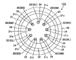
図1は、本発明の第1実施形態に係る液体検知ユニットの正面図である。図2は、図1のX−X線に沿う断面図である。図3は、図1の液体検知ユニットが有する検知素子部の背面図である。図4は、図1の液体検知ユニットが有する検知制御部の正面図である。図5は、図1の液体検知ユニットの電気回路の概略を示す図である。 FIG. 1 is a front view of a liquid detection unit according to the first embodiment of the present invention. FIG. 2 is a sectional view taken along the line XX of FIG. FIG. 3 is a rear view of the detection element unit included in the liquid detection unit of FIG. FIG. 4 is a front view of the detection control unit included in the liquid detection unit of FIG. FIG. 5 is a diagram showing an outline of an electric circuit of the liquid detection unit of FIG.
この液体検知ユニット(図中、符号1で示す)は、図1〜図4に示すように、検知素子部10と、検知制御部50(図2)とを有している。検知素子部10と検知制御部50とは、後述のベース20とハウジング60とにより一対のコネクタとして互いに嵌合可能に構成されている。この実施形態ではベース20とハウジング60が「ユニットケース」を構成している。
As shown in FIGS. 1 to 4, this liquid detection unit (indicated by
検知素子部10は、ベース20と、複数の導電端子30と、3枚の電極板40と、を有している。
The
ベース20は、例えば、ステンレス鋼などの金属を材料として構成されており、ベース本体部21と、円筒部22と、フランジ部23と、を一体に有しており、さらに、後述する複数の導電端子30を固定するハーメチックガラス24を有している。
The
ベース本体部21は、円板状に形成されている。円筒部22は、ベース本体部21と同軸となるようにベース本体部21の一方の面21aに突出して設けられている。ベース本体部21における円筒部22の内側の箇所には、一方の面21aと他方の面21bとを貫通する複数の貫通穴21c(図3)が形成されている。フランジ部23は、ベース本体部21の半径方向に突出するように、当該ベース本体部21の周面21dの全体にわたって設けられている。フランジ部23におけるベース本体部21の他方の面21bと同一方向を向く取付面23aは、環状の平面であって、後述する圧縮機101の筐体102に取り付ける際に、当該筐体102の「壁部」としての側壁部103に設けられた貫通穴103aを囲み当該側壁部103の外面に全体が密に接するように配置される。ハーメチックガラス24は、複数の貫通穴21c内に固着されている。
The
複数の導電端子30は、例えば、ニッケル合金などの導電性の金属を材料とし構成されており、それぞれが真っ直ぐに伸びる棒状に形成されている。複数の導電端子30のそれぞれは、対応する上記貫通穴21cに挿通されており、ハーメチックガラス24によりベース本体部21と電気的に絶縁された状態で当該ベース本体部21に固定して取り付けられている。なお、導電端子30をベース本体部21に固定するために、ハーメチックガラス24に代えて別の絶縁材を用いてもよい。複数の導電端子30は、それぞれの一部31がベース本体部21の他方の面21bから垂直に突出して配置され、他の一部32が円筒部22内の底面から垂直に突出して配置されている。各導電端子30の他の一部32は、後述する検知制御部50との嵌合時にオス端子として検知制御部50のメス端子と接触される。
The plurality of
本実施形態において、導電端子30を9本有し、3種類の長さのものを含んでいる。具体的には、複数の導電端子のうち3本が長く形成され(図中、符号30Lで示す)、これら3本より他の3本が短く形成され(図中、符号30Mで示す)、残りの3本がさらに短く形成されている(図中、符号30Sで示す)。各導電端子30L,30M,30Sは、正面方向から見て、正九角形の各頂点となるように周方向に順に配置されている。そして、複数の導電端子30(30L,30M,30S)は、それぞれの他の一部32の長さが同一となるように、ベース本体部21に固定されており、これにより、各導電端子30L,30M,30Sの一部31は、互いの長さが異なるようにされている。
In the present embodiment, there are nine
3枚の電極板40は、例えば、ステンレス鋼などの導電性の金属を材料として構成されており、それぞれが同一の円板状に形成されている。3枚の電極板40のうちの外側の電極板40Lは、上述した3本の導電端子30Lのそれぞれの一部31の先端に固定して取り付けられている。中央の電極板40Mは、上述した3本の導電端子30Mのそれぞれの一部31の先端に固定して取り付けられている。また、内側の電極板40Sは、他の3本の導電端子30Sのそれぞれの一部31の先端に固定して取り付けられている。これにより、電極板40Lと電極板40Mとの間、及び、電極板40Sと電極板40Mとの間に間隔が設けられるとともに、互いに平行に配置される。
The three
電極板40Mにおける3本の導電端子30Lに対応する箇所には、これら3本の導電端子30Lを挿通する貫通穴40aが設けられている。各貫通穴40aは、導電端子30Lと電極板40Mとが接触しないように形成されている。また、電極板40Sにおける6本の導電端子30L,30Mに対応する箇所には、これら6本の導電端子30L,30Mを挿通する貫通穴40aが設けられている。各貫通穴40aは、導電端子30L,30Mと電極板40Sとが接触しないように形成されている。各貫通穴40aは、導電端子30L,30Mを挿通した状態で絶縁材で塞がれていてもよい。
Through
各電極板40は、例えば、溶接やろう付けなどによって各導電端子30に取り付けられている。このように、長さの異なる導電端子30Lの一部31及び導電端子30Mの一部31のそれぞれの先端に、一方の電極板40L及び他方の電極板40Mが取り付けられることにより、これら電極板40L、40Mは、互いに間隔をあけて平行に配置される。また、長さの異なる導電端子30Mの一部31及び導電端子30Sの一部31のそれぞれの先端に、一方の電極板40M及び他方の電極板40Sが取り付けられることにより、これら電極板40M、40Sは、互いに間隔をあけて平行に配置される。また、電極板40L,40M,40Sは、フランジ部23の取付面23aとも平行に配置される。このように、各電極板40は、対応する各導電端子30に対して直角に配置されるとともに、ベース本体部21の他方の面21bに沿って、この他方の面21bと平行に配置されている。
Each
検知制御部50は、ハウジング60と、ケース70と、「検知回路」としての制御基板80と、を有している。
The
ハウジング60は、例えば、合成樹脂を材料として構成されており、ハウジング本体部61と、円柱部62と、基板収容部63と、を一体に有しており、さらに、シール部材64を有している。
The
ハウジング本体部61は、円板状に形成されている。円柱部62は、ハウジング本体部61と同軸となるようにハウジング本体部61の一方の面61aに突出して設けられている。円柱部62は、嵌合時に検知素子部10の円筒部22内に収容されるように、その外径が円筒部22の内径と略同一にされ、その高さが円筒部22の深さと略同一にされている。円柱部62には、その端面62aにおける複数の導電端子30に対応する箇所に開口し、メス端子(図示なし)を収容する端子孔62bが形成されている。基板収容部63は、ハウジング本体部61の他方の面61bに四角筒状に突出して設けられている。基板収容部63は、例えば、円筒形状など、その内側に後述する制御基板80を収容できるものであれば、その形状は任意である。
The
シール部材64は、例えばシリコーンゴムなどを材料として環状に形成され、ハウジング本体部61の一方の面61aに円筒部22を囲むように一部を露出して埋め込まれている。このシール部材64は、嵌合時に検知素子部10の円筒部22の端面22aによって押しつぶされて、検知素子部10と検知制御部50との間をシール(封止)する。
The
ケース70は、例えば、合成樹脂を材料として構成されており、円筒状の周壁部71と、周壁部71の一端を塞ぐ底壁部72と、を一体に有している。
The
周壁部71は、嵌合時に検知素子部10の円筒部22を収容するように、その内径が円筒部22の外径と略同一にされている。また、周壁部71の内周面には、嵌合時に円筒部22の外周面に形成された係止受孔(図示なし)に係止する係止爪(図示なし)が突出して形成されている。底壁部72には、基板収容部63を嵌め込み可能なように当該基板収容部63の平面視形状と略同一形状(本実施形態においては、四角形状)に形成された嵌込孔72aが形成されている。
The
制御基板80は、静電容量を検知する「検知回路」を構成する各種電子部品がプリント基板に実装されてなる電子基板である。制御基板80は、基板収容部63内に収容固定されており、リード線85を通じて上位の制御装置(図示なし)と接続されている。制御基板80は、端子孔62bに収容されたメス端子(図示なし)と接続されており、このメス端子が導電端子30の他の一部32(即ち、オス端子)と接触した状態において、一対の電極板40L,40M間の静電容量と、他の一対の電極板40S,40M間の静電容量を検知して、それぞれ当該静電容量に応じた検知信号をリード線85を通じて出力するように構成されている。制御基板80では、例えば、時定数や共振回路における共振周波数などに基づいて静電容量を検知し、静電容量の大きさに応じて変化する電圧信号(検知信号)を出力する。
The
検知素子部10と検知制御部50とは、図2に示す状態からさらに互いを近づけて嵌合させることにより、検知素子部10の導電端子30(オス端子)と検知制御部50のハウジング60内のメス端子とが接触して電気的に接続され、一対の電極板40間の液体状態に応じて変化する静電容量に応じた検知信号を出力する液体検知ユニット1を構成する。即ち、液体検知ユニット1は制御基板80により「検知回路」をハウジング60と一体としている。ここで、「液体状態」とは、液体の有無の他、例えば、液体に混入している不純物の割合なども含む。
The
図5に示すように、検知素子部10は、一対の電極板40L,40M間と、一対の電極板40M,40S間とに、それぞれ電荷を蓄える2つのキャパシタとみなすことができる。そして、液体検知ユニット1は、一対の電極板40L,40M間の静電容量と、一対の電極板40S,40M間の静電容量とをそれぞれ検知して、検知した静電容量に応じた二種の検知信号を出力する。この検知信号に基づいて、検知素子部10が取り付けられた高さにおける液体の有無、即ち、液面高さを検出することができる。また、検知信号が示す静電容量の値によって液体に混入している不純物の割合を検出することもできる。なお、この第1実施形態では、電極板40Mは、「GND」で示すグランド端子(フレームグランド)に接続され、電極板40L,40Sは、「+」で示す信号端子に接続されている。
As shown in FIG. 5, the
この例では、図2に示すように、一対の電極板40S,40Mの対向間隔は広く、一対の電極板40L,40Mの対向間隔は狭くなっている。即ち、複数の電極板40において電極板40Mは共通電極であり、対向間隔を広くした一対の電極板40S,40Mは「第1の電極対」を構成し、対向間隔を狭くした一対の電極板40L,40Mは「第2の電極対」を構成している。なお、一番内側の電極板40Sとベース本体部21の他方の面21bとの対向間隔は、一対の電極板40S,40Mの対向間隔よりも広くなっている。
In this example, as shown in FIG. 2, the facing distance between the pair of
そして、対向間隔の広い一対の電極板40S,4M(第1の電極対)に対応する検知信号により、液体の有無、即ち、液面高さを検出する。これにより、この実施形態では、圧縮機の油の切れを検出することができる。なお、油の切れが検出されたら、圧縮機は停止させる。また、対向間隔の狭い一対の電極板40L,40M(第2の電極対)に対応する検知信号により、液体に混入している不純物の割合を検出する。この不純物の割合は、この実施形態では圧縮機の内部の油の比誘電率として検出する。これにより、圧縮機において、冷媒と油がどの程度混合されているかを判定する。
Then, the presence or absence of the liquid, that is, the liquid level is detected by the detection signals corresponding to the pair of
このように、液体の有無の検出には、対向間隔の広い一対の電極板40S,40Mを用いているので、液体が無くなった場合には、一対の電極板40S,40Mの間から液体が確実に無くなり、さらに、電極板40Sと他方の面21bとの間からも液体が確実に無くなり、液体の無し状態を確実に検出することができる。また、不純物の割合(油の比誘電率)を検出するためには、対向間隔の狭い一対の電極板40L,40Mを用いているので、静電容量を精度良く検出することができる。このため、不純物の割合(油の比誘電率)を精度良く検出することができる。なお、この静電容量から不純物の割合(油の比誘電率)を求めるときは、一対の電極板40S,40Mで検出される液面の高さ、即ち、電極板40L,40M間の液面の高さに応じて、静電容量を不純物の割合に換算する。なお、この実施形態では、信号端子(+)に接続された電極板40Sがベース本体部21側に配置されているので、ベース本体部21等における浮遊電荷の影響を受ける可能性もあるが、仮に浮遊電荷の影響を受けても、この電極板40Sは液体の有無の検出に用いるものであり、静電容量を精度良く検出する必要がなく、問題はない。
As described above, since the pair of
ここで、制御基板80は、検知素子部10の導電端子30に直接接続されている。そして、制御基板80は、導電端子30のみを介して複数の電極板40における静電容量を感知し、検知回路内部でその静電容量に応じた電圧信号に変換する。そして、この電圧信号に対して各種の処理を施して、液面高さに対応する電圧信号(検知信号)を測定結果として、上位の制御装置に出力する。また、静電容量に応じた不純物の割合に対応する電圧信号(検知信号)を測定結果として上位の制御装置に出力する。
Here, the
以上のように、制御基板80は、検知素子部10の導電端子30に直接接続されており、この制御基板80は、導電端子30のみを介して複数の電極板40における静電容量を感知し、検知回路内部でその静電容量に応じた電圧信号に変換する。このように、検知回路(制御基板80)が液体検知ユニット1のユニットケースと一体としたことにより、この検知回路が感知する静電容量の殆どは一対の電極板40によるものである。導電端子30は棒状で、長さも検知素子部10の長さ程度であるため、この導電端子30による静電容量は極めて小さい。即ち、電極板40における静電容量に対する他の要因によるバイアスが小さいため、制御基板80で検知される静電容量のS/N比が良くなる。
As described above, the
また、液体検知ユニット1の検知素子部10は、例えば、図10に示すように、後述する圧縮機101の筐体102における鉛直方向に沿う側壁部103に取り付けられる。具体的には、筐体102の側壁部103には、検知素子部10のベース本体部21の外径より大きく、フランジ部23の外径より小さい円形状の貫通穴103aが形成されており、この貫通穴103aから複数の導電端子30の一部31及び4枚の電極板40を筐体102内に挿入して、フランジ部23の取付面23a全体を側壁部103の外面に当接させる。そして、フランジ部23を側壁部103に溶接して貫通穴103aを塞ぐ。次に、検知素子部10を圧縮機101に溶接した後、この検知素子部10に検知制御部50を嵌合させる。
Further, the
このように、検知素子部10と検知制御部50とを、一対のコネクタとしてコネクタ接続するよう構成されているので、検知素子部10の溶接時には、「検知回路」(制御基板80)を有する検知制御部50に溶接時の熱等が影響することない。したがって、制御基板80即ち検知回路も破損することがない。
As described above, since the
次に、本発明の第2実施形態に係る液体検知ユニットについて、図6〜図9を参照して説明する。この第2実施形態の液体検知ユニットも第1実施形態と同様に、後述する圧縮機の筐体の側壁に取り付けられて、当該筐体に収容された潤滑油の液面高さや、潤滑油への不純物の混入程度などの検知に用いられる。 Next, a liquid detection unit according to the second embodiment of the present invention will be described with reference to FIGS. 6 to 9. Similarly to the first embodiment, the liquid detection unit of the second embodiment is also attached to the side wall of the casing of the compressor to be described later, and the liquid level of the lubricating oil housed in the casing and the level of the lubricating oil It is used to detect the degree of contamination of impurities.
図6は、本発明の第2実施形態に係る液体検知ユニットの正面図である。図7は、図6のX−X線に沿う断面図である。図8は、図6の液体検知ユニットが有する検知素子部の背面図である。図9は、図6の液体検知ユニットを圧縮機に取り付けるフレアナット及び液体検知ユニットを示す断面図である。 FIG. 6 is a front view of the liquid detection unit according to the second embodiment of the present invention. FIG. 7 is a sectional view taken along line XX of FIG. FIG. 8 is a rear view of the detection element unit included in the liquid detection unit of FIG. FIG. 9 is a cross-sectional view showing a flare nut and a liquid detection unit for mounting the liquid detection unit of FIG. 6 on a compressor.
この液体検知ユニット(図中、符号1Aで示す)は、図6〜図8に示すように、検知素子部10Aと、検知制御部50A(図7)とを有している。
As shown in FIGS. 6 to 8, this liquid detection unit (indicated by
検知素子部10Aは、「第1ケース」としての継手ユニット20Aと、複数の導電端子30と、3枚の電極板40と、を有している。なお、導電端子30、電極板40及び制御基板80の概略構成は第1実施形態と同様であるので、これらの要素は第1実施形態と同符号を付記する。
The
継手ユニット20Aは、例えば、ステンレス鋼などの金属を材料として構成されている。この継手ユニット20Aは、軸線Pを中心軸とする円柱形状のフレア継手部25と、六角柱として形成した六角頭部26とを一体に有している。さらに、複数の導電端子30を固定するハーメチックガラス27を有している。この実施形態では継手ユニット20Aと後述の「第2ケース」としてのフレアナット200が「ユニットケース」を構成している。
The
フレア継手部25には、その外周に雄ねじ25aが形成されるとともに、先端の外周に円錐台の側面の形状をしたシール面25bが形成されている。また、フレア継手部25は、シール面25bの内側に先端凹部251を有するとともに、六角頭部26側にコネクタ凹部252を有している。さらに、フレア継手部25には、先端凹部251の底面とコネクタ凹部252の底面とを貫通する複数の貫通穴25c(図8)が形成されている。
The flare
複数の導電端子30は第1実施形態と同様にニッケル合金などの導電性の金属材料にて、それぞれが真っ直ぐに伸びる棒状に形成されている。複数の導電端子30のそれぞれは、対応する上記貫通穴25cに挿通されており、ハーメチックガラス27によりフレア継手部25と電気的に絶縁された状態で当該フレア継手部25に固定して取り付けられている。なお、導電端子30をフレア継手部25に固定するために、ハーメチックガラス27に代えて別の絶縁材を用いてもよい。複数の導電端子30は、それぞれの一部31が先端凹部251の底面から垂直に突出して配置され、他の一部32がコネクタ凹部252の底面から垂直に突出して配置されている。各導電端子30の他の一部32は、後述する検知制御部50Aとの嵌合時にオス端子として検知制御部50Aのメス端子と接触される。
Similar to the first embodiment, the plurality of
第1実施形態と同様に、導電端子30は9本有し、長く形成された3本の導電端子30Lと、これらより短く形成された他の3本の導電端子30Mと、さらに短く形成された残りの3本の導電端子30Sとで構成されている。各導電端子30L,30M,30Sは、正面方向から見て、正九角形の各頂点となるように周方向に順に配置され、各導電端子30L,30M,30Sは、コネクタ凹部252側の長さが同一となるようにフレア継手部25に軸線Pと平行に固定されている。これにより、各導電端子30L,30M,30Sの先端凹部251側の端部は、互いの長さが異なるようにされている。
As in the first embodiment, the number of
また、3枚の電極板40も第1実施形態と同様であり、ステンレス鋼などの導電性の金属材料にて構成され、それぞれが同一の円板状に形成されている。そして、外側の電極板40Lは3本の導電端子30Lのそれぞれの一部31の先端に固定して取り付けられ、中央の電極板40Mは、3本の導電端子30Mのそれぞれの一部31の先端に固定して取り付けられ、内側の電極板40Sは3本の導電端子30Sのそれぞれの一部31の先端に固定して取り付けられている。なお、各電極板40は、例えば、溶接やろう付けなどによって各導電端子30に取り付けられている。
Further, the three
これにより、電極板40L、電極板40M及び電極板40Sは、それらの間に間隔が設け、互いに平行に配置されるとともに、軸線Pと直角に配置されている。なお、図には現れていないが、電極板40Mには導電端子30Lと接触しないように貫通穴が形成され、電極板40Sには導電端子30L,30Mと接触しないように貫通穴が形成されている。
As a result, the
検知制御部50Aは、「検知回路」としての制御基板80と、円柱状のコネクタ90と、を有している。
The
コネクタ90は、フレア継手部25と同軸となるようにコネクタ凹部252内に設けられている。コネクタ90には、その端面90aにおける複数の導電端子30に対応する箇所に開口し、メス端子(図示なし)を収容する端子孔90bが形成されている。
The
制御基板80は、静電容量を検知する検知回路を構成する各種電子部品がプリント基板に実装されてなる電子基板である。制御基板80は、六角頭部26の基板収容部261内に収容されて図示しない部材により固定されている。そして、制御基板80は、リード線85を通じて上位の制御装置(図示なし)と接続されている。制御基板80は、コネクタ90の端子孔90bに収容されたメス端子(図示なし)と接続されており、このメス端子が導電端子30の他の一部32(即ち、オス端子)と接触した状態において、一対の電極板40L,40M間の静電容量と、他の一対の電極板40S,40M間の静電容量を検知して、それぞれ当該静電容量に応じた検知信号をリード線85を通じて出力するように構成されている。制御基板80では、例えば、時定数や共振回路における共振周波数などに基づいて静電容量を検知し、静電容量の大きさに応じて変化する電圧信号(検知信号)を出力する。
The
このように、この第2実施形態においても、検知素子部10Aと検知制御部50Aとは、第1実施形態と同様に、一対の電極板40間の液体状態に応じて変化する静電容量に応じた検知信号を出力する液体検知ユニット1を構成する。また、液体検知ユニット1Aは制御基板80により「検知回路」をユニットケースと一体としている。なお、この第2実施形態における液体検知ユニット1の電気回路は図5と同様である。
As described above, also in the second embodiment, the
この第2実施形態でも、対向間隔の広い一対の電極板40S,40Mに対応する検知信号により、液体の有無、即ち、液面高さを検出する。これにより、圧縮機の油の切れを検出することができる。また、対向間隔の狭い一対の電極板40L,40Mに対応する検知信号により、液体に混入している不純物の割合(圧縮機の内部の油の比誘電率)を検出することができる。
Also in the second embodiment, the presence or absence of liquid, that is, the liquid level is detected by the detection signals corresponding to the pair of
以上のように、制御基板80は、検知素子部10の導電端子30に直接接続されており、この制御基板80は、導電端子30のみを介して複数の電極板40における静電容量を感知し、検知回路内部でその静電容量に応じた電圧信号に変換する。このように、第1実施形態と同様に、制御基板80が液体検知ユニット1(ユニットケース)と一体としていることにより、この制御基板80が感知する静電容量の殆どは一対の電極板40によるものであり、導電端子30による静電容量は極めて小さい。したがって、検知回路(制御基板80)で検知される静電容量のS/N比が良くなる。
As described above, the
図9は第2実施形態に係る液体検知ユニットを圧縮機に取り付けるフレアナット及び液体検知ユニットを示す断面図である。なお、図9において液体検知ユニット1Aの符号の表記を一部省略してある。このフレアナット200はステンレス鋼などの金属を材料として構成されており、薄型円柱部210と、六角柱として形成した六角頭部220とを一体に形成したものである。薄型円柱部210には軸線Pを中心とする円形の開口部211が形成され、六角頭部220には軸線Pを中心として、上記開口部211に連通するねじ穴221が形成されている。ねじ穴221の内周には、フレア継手部25の雄ねじ25aに螺合する雌ねじ222が形成されている。また、ねじ穴221の開口部211の外周となる底部はすり鉢状のシール面221aとなっている。
FIG. 9 is a sectional view showing a flare nut and a liquid detection unit for mounting the liquid detection unit according to the second embodiment on a compressor. In addition, in FIG. 9, the notation of the reference numerals of the
六角頭部220における薄型円柱部210側の面は軸線Pに直交する取付面223は環状の平面である。このフレアナット200を後述する圧縮機101の筐体102に取り付ける際に、当該筐体102の側壁部103に設けられた貫通穴103a内に、薄型円柱部210を嵌合させ、取付面223によって該貫通穴103aの外周を囲み当該側壁部103の外面に取付面223の全体が密に接するように配置される。そして、取付面223の外周全周に亘って、六角頭部220と側壁部103との間を溶接することで、当該フレアナット200が圧縮機101の筐体102に固定される。
The surface of the
このフレアナット200を筐体102に溶接して固定した後、液体検知ユニット1Aのフレア継手部25を六角頭部220のねじ穴221に嵌合して、雄ねじ25aを雌ねじ222にねじ込み、フレア継手部25のシール面25bをシール面221aに圧接させて、シール面25bとシール面221aとによって金属シールする。シール面25bとシール面221aとの間に別途のシール部材を介在させてもよい。なお、液体検知ユニット1Aを溶接後のフレアナット200にねじ込む際には、フレアナット200の六角頭部220をスパナ等で保持し、液体検知ユニット1Aの六角頭部26をスパナ等で保持してねじ込む。
After the
以上のように、液体検知ユニット1Aをフレアナット200を介して圧縮機101に取り付けると、電極板40の部分が薄型円柱部210の開口部211から筐体102内に内に挿入された状態となる。このように、検知回路(制御基板80)を一体とした液体検知ユニット1Aは、フレアナット200に対して、金属シール構造(フレアシール構造)で取付けるよう構成されているので、フレアナット200の溶接時には、「検知回路」(制御基板80)を一体とした液体検知ユニット1Aに溶接時の熱等の影響を防止できる。したがって、制御基板80即ち検知回路も破損することがない。
As described above, when the
この第2実施形態では、ユニットケースが、複数の導電端子30を取り付けた金属製で円柱形状のフレア継手部25を有するとともに検知回路を収容固定した継手ユニット20A(第1ケース)と、検知対象の液体を収容する筺体及び継手ユニット20A間に介在される金属製のフレアナット200(第2ケース)と、で構成され、フレア継手部25には、外周に雄ねじ25aが形成されるとともに、電極板40が配置される側の先端の外周に円錐台の側面の形状をしたシール面25bが形成され、フレアナット200には、端部の開口部211に連通するねじ穴221の内周に雄ねじ25aに螺合する雌ねじ222が形成されるとともに、ねじ穴221の開口部211の外周となる底部にすり鉢状のシール面221aが形成され、フレア継手部25のシール面25bと、フレアナット200のシール面221aとにより金属シール構造をとるようにしている。
In the second embodiment, the unit case has a metal-made cylindrical flare
しかし、変形例として、圧縮機の筐体に溶接されるフレアナット側に、円柱形状の継手でその外周に雄ねじが形成され中心に開口部を有する継手を設け、さらのこの継手の端部に円錐台の側面の形状をしたシール面を形成し、導電端子が取り付けられるとともに検知回路を収容固定した継手ユニット側に上記雄ねじに螺合する雌ねじを設けるとともに、この雌ねじの端部にすり鉢状のシール面を形成するようにしてもよい。そして、継手ユニット側の導電端子及び電極板をフレアナット側の開口部に挿通するようにしてもよい。 However, as a modification, on the flare nut side to be welded to the casing of the compressor, a joint having a columnar shape with a male thread formed on the outer periphery and an opening at the center is provided, and at the end of this joint Form a sealing surface in the shape of a side of a truncated cone, and provide a female screw that engages with the male screw on the side of the joint unit that has the conductive terminal attached and the detection circuit is housed and fixed, and the end of this female screw is shaped like a mortar. You may make it form a sealing surface. Then, the conductive terminal and the electrode plate on the joint unit side may be inserted into the opening on the flare nut side.
上述した実施形態では、3枚の電極板40を有する構成であったが、これに限定するものではない。例えば、4枚の電極板を有する構成、5枚以上の電極板を有する構成でもよい。
In the above-described embodiment, the configuration has three
上述した実施形態では、各電極板40が円板状に形成された構成であったが、これに限定されるものではなく、電極板40は、それら形状や大きさなどについて任意である。但し、液体が複数の電極板40に接する高さのばらつきを抑制する、即ち、検出精度のばらつきを抑制する観点から、電極板40は、円板状又は正三角形板状、正方形板状、正六角形板状若しくは正八角形板状などの正多角形板状に形成されていることが好ましい。
In the above-described embodiment, each
また、上述した第1実施形態では、検知素子部10と検知制御部50とが別体であり、これらが一対のコネクタとして嵌合可能に構成されていたが、これに限定されるものではなく、検知素子部10と検知制御部50とを一体として構成して液体検知ユニットであってもよい。
Further, in the above-described first embodiment, the
(圧縮機の実施形態)
以下に、本発明の一実施形態に係る圧縮機について、図10を参照して説明する。図10は、本発明の一実施形態に係る圧縮機の断面図である。この圧縮機は、例えば、空気調和機の冷媒回路に設けられて、冷媒回路内の冷媒の循環等のために用いられる。
(Embodiment of compressor)
Below, the compressor which concerns on one Embodiment of this invention is demonstrated with reference to FIG. FIG. 10 is a cross-sectional view of the compressor according to the embodiment of the present invention. This compressor is provided, for example, in a refrigerant circuit of an air conditioner and is used for circulating the refrigerant in the refrigerant circuit.
圧縮機101は、ロータリー方式を採用しており、筐体102内に、モータ固定子111及びモータ回転子112を有するモータ部110と、シリンダ121及びシリンダ121に形成された作動室122に収容された環状ピストン125を有する圧縮部120と、が配設されている。モータ回転子112と環状ピストン125とは、クランク軸130によって連結されている。また、筐体102内に、圧縮部120等の潤滑等のための潤滑油Kが収容されている。
The
圧縮機101は、モータ部110によってクランク軸130が回転されると、環状ピストン125が、その外周面の一部を作動室122の周壁面に接しながら回転される。環状ピストン125の回転に応じて、吸入管141から吸入マフラ142、導入管143を通じて、作動室122内に冷媒が導入される。そして、この冷媒が作動室122内において環状ピストン125によって圧縮されて、吐出マフラ144、筐体102、吐出管145を通じて圧縮機101外部に導出される。
In the
また、圧縮機101は、上述した液体検知ユニット1を有している。液体検知ユニット1の検知素子部10は、筐体102における鉛直方向に沿う側壁部103に取り付けられている。具体的には、検知素子部10は、側壁部103に設けられた貫通穴103aに複数の導電端子30の一部31及び二対の電極板40が挿入されるとともに、ベース20のフランジ部23の取付面23a全体が貫通穴103aの周囲において側壁部103の外面に接した状態で、当該フランジ部23が溶接により固定されている。
Further, the
検知素子部10の3枚の電極板40は、筐体102内において鉛直方向に沿って互いに平行に配置されている。検知素子部10は、潤滑油Kが適量となる正常状態において3枚の電極板40の全体が液面下に沈み、潤滑油Kが不足している異常状態において3枚の電極板40の一部又は全体が液面上に露出するように配置されている。
The three
以上より本実施形態によれば、上述した液体検知ユニット1を有しているので、検知素子部10の取付スペースを小さくできるとともに、破損による故障を抑制でき、そのため、小型で故障の少ないものとすることができる。なお、図10は第1実施形態の液体検知ユニット1を有している例を示しているが、第2実施形態の液体検知ユニット1Aも、上記圧図10の縮機101に対して、前記図9について説明したとおりに取り付けられるものである。
As described above, according to the present embodiment, since the
上述した実施形態では、ロータリー方式を採用した構成であったが、これに限定されるものではなく、例えば、スクロール方式など他の方式を採用した構成のものであってもよい。 In the above-described embodiment, the rotary system is adopted, but the present invention is not limited to this, and may be a structure adopting another system such as a scroll system.
(空気調和機の実施形態)
以下に、本発明の一実施形態に係る空気調和機について、図11を参照して説明する。図11は、本発明の一実施形態に係る空気調和機の概略構成を示す図である。この空気調和機は、例えば、家屋や商業施設などに設けられるエアコン等として用いられる。
(Embodiment of air conditioner)
Below, the air conditioner which concerns on one Embodiment of this invention is demonstrated with reference to FIG. FIG. 11: is a figure which shows schematic structure of the air conditioner which concerns on one Embodiment of this invention. This air conditioner is used, for example, as an air conditioner installed in a house or a commercial facility.
空気調和機201は、室内熱交換器211と、室外熱交換器212と、膨張弁213と、上述した圧縮機101と、流路切換弁215とを含む冷媒回路210を備えている。
The
空気調和機201の冷凍サイクルの流路は流路切換弁215により「冷房モード」および「暖房モード」の2通りの流路に切換えられる。冷房モードでは、図11に実線の矢印で示すように、圧縮機101で圧縮された冷媒は流路切換弁215から室外熱交換器212に流入され、膨張弁213に流入される。そして、この膨張弁213で冷媒が膨張され、室内熱交換器211に流入される。この室内熱交換器211に流入された冷媒は、流路切換弁215を介して圧縮機101に流入される。一方、暖房モードでは、図11に破線の矢印で示すように、圧縮機101で圧縮された冷媒は流路切換弁215から室内熱交換器211に流入され、膨張弁213に流入される。そして、この膨張弁213で冷媒が膨張され、室外熱交換器212、流路切換弁215、圧縮機101の順に循環される。
The flow path of the refrigeration cycle of the
冷房モードでは、室外熱交換器212が凝縮器として機能し、室内熱交換器211が蒸発器として機能し、室内の冷房がなされる。また、暖房モードでは、室外熱交換器212が蒸発器として機能し、室内熱交換器211が凝縮器として機能し、室内の暖房がなされる。
In the cooling mode, the
以上より、本実施形態によれば、上述した液体検知ユニット1を有する圧縮機101を備えているので、小型で故障の少ない空気調和機201とすることができる。
As described above, according to the present embodiment, since the
以上の実施形態では、導電端子30は棒状のものであるが、これに限らず、導電端子は、電極板40と一体に形成した、あるいは別体に形成した、帯状のものでもよい。
In the above embodiment, the
以上の実施形態では、液体検知ユニットを圧縮機の側壁部に取り付ける例について説明したが筐体の底部やその他の箇所に取り付けるようにしてもよい。 In the above embodiment, the example in which the liquid detection unit is attached to the side wall portion of the compressor has been described, but the liquid detection unit may be attached to the bottom portion of the housing or other places.
なお、前述した実施形態は本発明の代表的な形態を示したに過ぎず、本発明は、実施形態に限定されるものではない。即ち、当業者は、従来公知の知見に従い、本発明の骨子を逸脱しない範囲で種々変形して実施することができる。かかる変形によってもなお本発明の液体検知ユニット、圧縮機及び空気調和機の構成を具備する限り、勿論、本発明の範疇に含まれるものである。 It should be noted that the above-described embodiment merely shows a typical form of the present invention, and the present invention is not limited to the embodiment. That is, those skilled in the art can carry out various modifications according to the conventionally known knowledge without departing from the gist of the present invention. Such a modification is of course included in the scope of the present invention as long as it has the configurations of the liquid detection unit, the compressor, and the air conditioner of the present invention.
1,1A 液体検知ユニット
10、10A 検知素子部
20 ベース(ユニットケース)
23a 取付面
24 ハーメチックガラス
30 導電端子
31 導電端子の一部
32 導電端子の他の一部
40 電極板
50 検知制御部
60 ハウジング(ユニットケース)
20A 継手ユニット(ユニットケース)
25a 雄ねじ
25b シール面
200 フレアナット(ユニットケース)
221a シール面
222 雌ねじ
101 圧縮機
102 筐体
103 側壁部(壁部)
103a 貫通穴
201 空気調和機
210 冷媒回路
211 室内熱交換器
212 室外熱交換器
213 膨張弁
215 流路切換弁
K 潤滑油
1, 1A
20A joint unit (unit case)
103a Through
Claims (5)
前記電極板が取り付けられた複数の導電端子と、
前記導電端子を介して前記電極板の間の静電容量を検知して当該静電容量に応じた検知信号を出力する検知回路と、
前記複数の導電端子と前記検知回路を収めることができるユニットケースと、
円筒状の周壁部、及び、該周壁部の一端を塞ぐ底壁部を備えたケースと、
を有し、
前記導電端子と、前記導電端子に電気的に接続された前記検知回路をユニットケースにて一体とし、
複数の前記電極板のそれぞれに対し、複数の前記導電端子が、他の前記電極板とは独立に設けられており、
前記導電端子は、前記電極板と反対側の端部がオス端子となっており、
前記検知回路には、メス端子が接続されており、
前記オス端子と前記メス端子とが接触することにより、前記検知回路が前記電極板の間の静電容量を検知し、
前記ユニットケースが、前記複数の導電端子を取り付けたベースと、前記検知回路を収容固定したハウジングとで構成され、前記ユニットケースが、前記ベースと前記ハウジングとにより一対のコネクタとして互いに嵌合可能とされ、
前記ベースが、前記導電端子が配置される円筒部を有し、
前記ハウジングが、前記メス端子が形成された円柱部を有し、
前記円柱部が前記円筒部内に収容されることで嵌合するとともに、前記ケースが前記ベースとの間に前記ハウジングを挟み込み、前記円筒部が前記周壁部内に収容されることで嵌合することを特徴とする液体検知ユニット。 A liquid detection unit for detecting a liquid by electrostatic capacitance between a plurality of electrode plates,
A plurality of conductive terminals to which the electrode plate is attached,
A detection circuit that detects the electrostatic capacitance between the electrode plates via the conductive terminal and outputs a detection signal according to the electrostatic capacitance,
A unit case capable of accommodating the plurality of conductive terminals and the detection circuit;
A case having a cylindrical peripheral wall portion and a bottom wall portion closing one end of the peripheral wall portion;
Have
Integrating the conductive terminal and the detection circuit electrically connected to the conductive terminal in a unit case,
For each of the plurality of electrode plates, the plurality of conductive terminals are provided independently of the other electrode plates,
The conductive terminal has a male terminal at the end opposite to the electrode plate,
A female terminal is connected to the detection circuit,
By contact between the male terminal and the female terminal, the detection circuit detects the capacitance between the electrode plates,
The unit case is composed of a base to which the plurality of conductive terminals are attached and a housing in which the detection circuit is housed and fixed, and the unit case can be fitted to each other as a pair of connectors by the base and the housing. Is
The base has a cylindrical portion in which the conductive terminal is arranged,
The housing has a cylindrical portion on which the female terminal is formed,
The cylindrical portion is fitted in by being accommodated in the cylindrical portion, and the housing is sandwiched between the case and the base, and the cylindrical portion is fitted in by being accommodated in the peripheral wall portion. Characteristic liquid detection unit.
前記ユニットケースが、前記筐体の壁部に設けられた貫通穴を塞ぐように当該壁部に取り付けられ、
前記複数の導電端子が、前記筐体内に少なくとも一部が配置されるように前記ユニットケースの一つの面から突出して取り付けられ、
前記複数の電極板が、前記ユニットケースの一つの面に沿って互いに平行に配置されるように、前記複数の導電端子のうちの対応する導電端子の前記一部にそれぞれ取り付けられている
ことを特徴とする請求項1に記載の液体検知ユニット。 The liquid detection unit according to claim 1, which is used to detect a liquid contained in a housing,
The unit case is attached to the wall portion so as to close a through hole provided in the wall portion of the housing,
The plurality of conductive terminals are attached so as to project from one surface of the unit case so that at least a part of the conductive terminals is arranged in the housing,
The plurality of electrode plates are respectively attached to the portions of the corresponding conductive terminals of the plurality of conductive terminals so as to be arranged in parallel to each other along one surface of the unit case. The liquid detection unit according to claim 1, wherein the liquid detection unit is a liquid detection unit.
前記液体検知部が、請求項1〜3のいずれか一項に記載の液体検知ユニットを含んで構成されていることを特徴とする圧縮機。 A compressor having a housing, a compression section provided in the housing, and a liquid detection section for detecting a lubricating oil housed in the housing,
The said liquid detection part is comprised including the liquid detection unit in any one of Claims 1-3, The compressor characterized by the above-mentioned.
Priority Applications (1)
| Application Number | Priority Date | Filing Date | Title |
|---|---|---|---|
| JP2019119516A JP6735882B2 (en) | 2019-06-27 | 2019-06-27 | Liquid detection unit, compressor and air conditioner |
Applications Claiming Priority (1)
| Application Number | Priority Date | Filing Date | Title |
|---|---|---|---|
| JP2019119516A JP6735882B2 (en) | 2019-06-27 | 2019-06-27 | Liquid detection unit, compressor and air conditioner |
Related Parent Applications (1)
| Application Number | Title | Priority Date | Filing Date |
|---|---|---|---|
| JP2014222373A Division JP2016090302A (en) | 2014-10-31 | 2014-10-31 | Liquid detection unit, compressor and air conditioner |
Publications (2)
| Publication Number | Publication Date |
|---|---|
| JP2019179041A JP2019179041A (en) | 2019-10-17 |
| JP6735882B2 true JP6735882B2 (en) | 2020-08-05 |
Family
ID=68278383
Family Applications (1)
| Application Number | Title | Priority Date | Filing Date |
|---|---|---|---|
| JP2019119516A Expired - Fee Related JP6735882B2 (en) | 2019-06-27 | 2019-06-27 | Liquid detection unit, compressor and air conditioner |
Country Status (1)
| Country | Link |
|---|---|
| JP (1) | JP6735882B2 (en) |
Family Cites Families (4)
| Publication number | Priority date | Publication date | Assignee | Title |
|---|---|---|---|---|
| US4591946A (en) * | 1985-04-30 | 1986-05-27 | Southwest Pump Company | Capacitance probe for use in a measuring system for location of a liquid level interface |
| JP3550229B2 (en) * | 1995-09-29 | 2004-08-04 | 株式会社不二工機 | Refrigerant amount detector and refrigerant state detector |
| AU2434497A (en) * | 1996-04-03 | 1997-10-22 | Robertshaw Controls Company | Fluid sensor |
| JP3895048B2 (en) * | 1998-06-23 | 2007-03-22 | 株式会社日本自動車部品総合研究所 | Capacitive sensor device |
-
2019
- 2019-06-27 JP JP2019119516A patent/JP6735882B2/en not_active Expired - Fee Related
Also Published As
| Publication number | Publication date |
|---|---|
| JP2019179041A (en) | 2019-10-17 |
Similar Documents
| Publication | Publication Date | Title |
|---|---|---|
| US10485128B2 (en) | Compressor protection module | |
| US7568894B2 (en) | Hermetic compressor | |
| CN103808450B (en) | Pressure-measuring plug for combustion engine | |
| KR101452767B1 (en) | Oil level detecting means for compressor | |
| US8162541B2 (en) | Two-terminal temperature sensor with electrically isolated housing | |
| US20160230763A1 (en) | Rotary Compressor With Vapor Injection System | |
| JP6516442B2 (en) | Liquid detector, compressor and air conditioner | |
| US20240044734A1 (en) | Sensor assembly and valve device | |
| JP6735882B2 (en) | Liquid detection unit, compressor and air conditioner | |
| BRPI0714435A2 (en) | device for pressure detection | |
| US8021125B2 (en) | Hermetic compressor | |
| JP6534253B2 (en) | Liquid detector, compressor and air conditioner | |
| JP6579743B2 (en) | Liquid detector, compressor and air conditioner | |
| JP6706880B2 (en) | Liquid detector, compressor and air conditioner | |
| JP2016090302A (en) | Liquid detection unit, compressor and air conditioner | |
| WO2019049430A1 (en) | Fluid property detection device | |
| JP6778783B2 (en) | Liquid detector, compressor and air conditioner | |
| JP6445842B2 (en) | Liquid detector, compressor and air conditioner | |
| US10969286B2 (en) | Pressure sensor | |
| US9606014B2 (en) | Pressure detector | |
| JP6472639B2 (en) | Liquid detection unit, compressor and air conditioner | |
| KR20160054779A (en) | Turbo chiller | |
| US20150160084A1 (en) | Passive Pressure Sensing | |
| JP2005325733A (en) | Hermetic compressor | |
| JP2015197349A (en) | Oil level sensor, compressor, and mounting method of oil level sensor onto compressor |
Legal Events
| Date | Code | Title | Description |
|---|---|---|---|
| A621 | Written request for application examination |
Free format text: JAPANESE INTERMEDIATE CODE: A621 Effective date: 20190627 |
|
| A977 | Report on retrieval |
Free format text: JAPANESE INTERMEDIATE CODE: A971007 Effective date: 20200421 |
|
| TRDD | Decision of grant or rejection written | ||
| A01 | Written decision to grant a patent or to grant a registration (utility model) |
Free format text: JAPANESE INTERMEDIATE CODE: A01 Effective date: 20200630 |
|
| A61 | First payment of annual fees (during grant procedure) |
Free format text: JAPANESE INTERMEDIATE CODE: A61 Effective date: 20200714 |
|
| R150 | Certificate of patent or registration of utility model |
Ref document number: 6735882 Country of ref document: JP Free format text: JAPANESE INTERMEDIATE CODE: R150 |
|
| LAPS | Cancellation because of no payment of annual fees |