JP6735552B2 - Member for fixing display device by electrostatic attraction and display device - Google Patents
Member for fixing display device by electrostatic attraction and display device Download PDFInfo
- Publication number
- JP6735552B2 JP6735552B2 JP2015239059A JP2015239059A JP6735552B2 JP 6735552 B2 JP6735552 B2 JP 6735552B2 JP 2015239059 A JP2015239059 A JP 2015239059A JP 2015239059 A JP2015239059 A JP 2015239059A JP 6735552 B2 JP6735552 B2 JP 6735552B2
- Authority
- JP
- Japan
- Prior art keywords
- display device
- electrode
- base material
- flexible substrate
- support
- Prior art date
- Legal status (The legal status is an assumption and is not a legal conclusion. Google has not performed a legal analysis and makes no representation as to the accuracy of the status listed.)
- Active
Links
Images


Landscapes
- Liquid Crystal (AREA)
- Devices For Indicating Variable Information By Combining Individual Elements (AREA)
Description
本発明は、表示装置を静電吸着により固定する部材、及び当該部材を有する表示装置に関する。 The present invention relates to a member for fixing a display device by electrostatic attraction and a display device having the member.
近年、液晶パネル、有機ELパネルなどを用いた表示装置の薄型化及び軽量化に伴い、壁などの支持体に表示装置を取付けて使用することが検討されている。例えば、特許文献1及び2には、ネジ、接着剤などを用いて壁にフックのような連結用部材を取付け、この連結用部材に、表示装置の背面に設けられた取付け用部材を連結する方法が提案されている。
2. Description of the Related Art In recent years, as display devices using liquid crystal panels, organic EL panels, etc. have become thinner and lighter, it has been studied to mount the display devices on a support such as a wall for use. For example, in
また、表示装置の中でもフレキシブルな表示装置(以下、「フレキシブルディスプレイ」と言うことがある)は、ペーパー状の薄い表示デバイスであり、紙のように丸めたり、曲げたりすることができる。したがって、フレキシブルディスプレイは、平面状の支持体だけでなく曲面状の支持体にも取付けることが可能であると共に、運搬や収納する際にも便利である。 Further, among display devices, a flexible display device (hereinafter, also referred to as “flexible display”) is a thin paper-like display device and can be rolled or bent like a paper. Therefore, the flexible display can be attached not only to a flat support but also to a curved support, and is convenient for transportation and storage.
しかしながら、壁などの支持体に表示装置を取付ける従来の方法は、ネジ、接着剤などを用いて支持体に連結用部材を取付ける必要がある。そのため、表示装置の設置位置を変更する場合などのように支持体から連結用部材を除去する際に支持体に傷や汚れなどをつけてしまうという問題がある。
また、表示装置がフレキシブルディスプレイである場合、丸めた状態で運搬及び収納されていたフレキシブルディスプレイを広げて支持体に取付けると、フレキシブルディスプレイに湾曲やうねりが生じ易いという問題もある。
However, in the conventional method of attaching the display device to the support such as a wall, it is necessary to attach the connecting member to the support by using a screw, an adhesive or the like. Therefore, when removing the connecting member from the support such as when changing the installation position of the display device, there is a problem that the support is damaged or soiled.
In addition, when the display device is a flexible display, if the flexible display that has been transported and stored in a rolled state is unfolded and attached to the support, there is a problem that the flexible display is likely to be curved or wavy.
本発明は、上記のような問題を解決するためになされたものであり、壁などの支持体に傷や汚れをつけずに表示装置を取付けることができると共に、取付けた際に表示装置の湾曲やうねりを防止することができる部材、及び当該部材を有する表示装置を提供することを目的とする。 The present invention has been made to solve the above problems, and it is possible to mount a display device without damaging or soiling a support such as a wall, and to bend the display device when mounted. An object of the present invention is to provide a member capable of preventing undulation and a display device including the member.
本発明者らは、表示装置を静電吸着により固定することができれば上記の問題を解決し得るであろうという想定の下、表示装置を静電吸着により固定するのに適した部材について鋭意研究を続けた結果、本発明を完成するに至った。
すなわち、本発明は、フレキシブル基材と、前記フレキシブル基材中又は前記フレキシブル基材上に設けられ且つ外部電源と電気的に接続可能である電極とを備え、表示装置を静電吸着により固定することを特徴とする部材である。
また、本発明は、前記部材を有することを特徴とする表示装置である。
The present inventors have diligently studied a member suitable for fixing a display device by electrostatic attraction under the assumption that the above-mentioned problem could be solved if the display device can be fixed by electrostatic attraction. As a result, the present invention has been completed.
That is, the present invention includes a flexible base material and an electrode provided in or on the flexible base material and electrically connectable to an external power source, and fixes the display device by electrostatic attraction. It is a member characterized by the above.
Further, the present invention is a display device including the member.
本発明によれば、壁などの支持体に傷や汚れをつけずに表示装置を取付けることができると共に、取付けた際に表示装置の湾曲やうねりを防止することができる部材、及び当該部材を有する表示装置を提供することができる。 According to the present invention, a display device can be attached without damaging or soiling a support such as a wall, and a member capable of preventing the display device from curving or waviness when attached, and the member. A display device having the same can be provided.
表示装置を静電吸着により固定する本発明の部材は、フレキシブル基材と、フレキシブル基材中又はフレキシブル基材上に設けられ且つ外部電源と電気的に接続可能である電極とを備える。
以下、本発明の部材の好適な実施の形態について図面を用いて説明する。
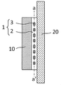
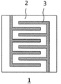
図1は、本発明の部材を介して表示装置を静電吸着によって支持体に固定した状態の断面図である。また、図2は、図1における本発明の部材1をa−a’線で切断したときの断面図である。
図1において、本発明の部材1は、フレキシブル基材2と、フレキシブル基材2中に設けられた電極3とを有する。このような構成を有する本発明の部材1は、静電吸着によって表示装置10を支持体20に固定することができる。
The member of the present invention for fixing a display device by electrostatic attraction includes a flexible base material and an electrode provided in or on the flexible base material and electrically connectable to an external power supply.
Hereinafter, preferred embodiments of the member of the present invention will be described with reference to the drawings.
FIG. 1 is a cross-sectional view showing a state in which a display device is fixed to a support by electrostatic attraction via the member of the present invention. 2 is a sectional view of the
In FIG. 1, the
フレキシブル基材2は、絶縁性を有し且つ内部に電荷を保持することが可能なものであれば特に限定されず、一般に誘電体から形成される。誘電体は、有機材料、無機材料、又は有機物と無機物との複合材料のいずれであってもよい。誘電体の具体例としては、酸化アルミニウムなどのセラミックス;ポリイミド、ポリプロピレン、ポリエチレン、ポリエチレンテレフタレート、ポリエチレンナフタレート、アラミド、ポリエーテルサルフォン、ポリエーテルケトン、ポリテトラフルオロエチレン、エポキシ樹脂、フッ素樹脂(例えば、テフロン(登録商標))などの樹脂;シリコンゴムなどのゴムなどが挙げられる。これらの材料は、単独又は2種以上を組み合わせて用いることができる。また、これらの中でも、シリコンゴム、フッ素樹脂、ポリプロピレン及びポリエチレンは、絶縁性に優れており、内部に電荷を保持し易いため好ましい。
The
有機物と無機物との複合材料としては、上記の樹脂に無機物の微細粉末を添加したものを用いることができる。無機物としては、炭酸カルシウム、焼成クレイ、シリカ、珪藻土、白土、タルク、酸化チタン、酸化ジルコニア、硫酸バリウム、チタン酸バリウム、アルミナ、ゼオライト、マイカ、セリサイト、ベントナイト、セピオライト、バーミキュライト、ドロマイト、ワラストナイト、ガラスファイバーなどが挙げられる。これらは単独又は2種以上を組み合わせて用いることができる。また、無機物の微細粉末の粒径は、特に限定されないが、レーザー回折による粒度分布計で測定した平均粒径が一般に0.01μm〜15μmである。様々な複合材料の中でも、その中でも、エポキシアクリレート系樹脂に酸化ジルコニアを添加した複合材料は、絶縁性に優れており、内部に電荷を保持し易いため好ましい。 As the composite material of the organic substance and the inorganic substance, a material obtained by adding fine powder of the inorganic substance to the above resin can be used. As the inorganic substances, calcium carbonate, calcined clay, silica, diatomaceous earth, white clay, talc, titanium oxide, zirconia oxide, barium sulfate, barium titanate, alumina, zeolite, mica, sericite, bentonite, sepiolite, vermiculite, dolomite, wollast. Examples include knight and glass fiber. These may be used alone or in combination of two or more. The particle size of the inorganic fine powder is not particularly limited, but the average particle size measured by a particle size distribution analyzer by laser diffraction is generally 0.01 μm to 15 μm. Among various composite materials, among them, a composite material in which zirconia oxide is added to an epoxy acrylate resin is preferable because it has excellent insulating properties and easily retains electric charge inside.
フレキシブル基材2の厚さは、特に限定されないが、好ましくは200μm以下、より好ましくは20μm〜200μmである。フレキシブル基材2の厚さが200μm超過であると、部材1のフレキシブル性が損なわれることがある。また、フレキシブル基材2の厚さが20μm未満であると、絶縁性が不足し、内部に電荷を保持することができないことがある。
The thickness of the
電極3としては、導電性を有することが可能なものであれば特に限定されず、当該技術分野において公知の材料から形成される。電極3を構成する材料の具体例としては、Cu、ITO、Alなどが挙げられる。これらは、単独又は2種以上を組み合わせて用いることができる。
電極3のパターン形状は、外部電源と電気的に接続可能な部分を有していれば特に限定されず、静電吸着方式の種類に応じて各種パターンを採用すればよい。例えば、電極3のパターン形状として、図2に示すような櫛歯状パターンを用いることができる。また、静電吸着方式の種類としては、クーロン力型、ジョンソン・ラベック力型、グラジエント力型などを用いることができる。
The
The pattern shape of the
電極3の厚さは、導電性が確保され得る範囲であれば特に限定されないが、好ましくは150μm以下、より好ましくは50nm〜50μmである。電極3の厚さが150μm超過であると、部材1のフレキシブル性が損なわれることがある。また、電極3の厚さが50nm未満であると、導電性が十分に確保されないことがある。
The thickness of the
電極3は、一般に、その端部が外部電源と電気的に接続される。ここで、外部電源としては、特に限定されず、電源コードなどの接続手段を介して外部電源に直接的に接続されるか、又は外部電源に接続された表示装置10から電源コードなどの接続手段を介して間接的に接続される。また、外部電源と電極3の端部との間に、蓄電可能な補助電源を設けてもよい。このような補助電源を設けることにより、停電などが生じた場合にも、表示装置10を支持体20に固定することが可能となる。
The
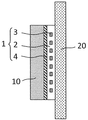
電極3は、フレキシブル基材2中に設けることができるが、フレキシブル基材2上に設けてもよい。フレキシブル基材2上に電極3を設ける場合、図3に示すように表示装置10側のフレキシブル基材2上に電極3を設ければよい。ただし、フレキシブル基材2上に電極3を設ける場合、フレキシブル基材2中に電極3を設ける場合に比べて製造が容易であるものの、電極3の間にゴミなどが入り込み易くなり、部材1の静電吸着能力が低下することがある。そのため、部材1の静電吸着能力を長期に渡って保持する観点から、電極3はフレキシブル基材2中に設けることが好ましい。
The
電極3をフレキシブル基材2中に設ける方法としては、特に限定されず、当該技術分野において公知の方法を用いることができる。
例えば、フレキシブル基材2を2層構造とする場合、一方のフレキシブル基材2の表面に電極3を蒸着、貼着、塗布などによって形成した後、他方のフレキシブル基材2をその上に貼付ければよい。或いは、電極3をモールドの所定の位置に配置した後、フレキシブル基材2の材料をモールドに流し込むことによって形成してもよい。
また、フレキシブル基材2上に電極3を設ける場合、フレキシブル基材2の表面に電極3を蒸着、貼着、塗布などによって形成すればよい。
The method for providing the
For example, in the case where the
When the
本発明の部材1は、フレキシブル基材2及び電極3のみから構成されていてもよいが、表示装置10に対する部材1の接着性を確保する観点から、図4に示すように表示装置10側と接するフレキシブル基材2の表面に接着層4をさらに設けてもよい。
接着層4としては、特に限定されず、当該技術分野において公知のものを用いることができる。接着層4の例としては、ゴム系接着剤、アクリル系接着剤、ポリ(ビニルエーテル)系接着剤、シリコン系接着剤などを用いて形成することができる。これらは、単独又は2種以上を組み合わせて用いることができる。その中でも、アクリル系接着剤は優れた接着特性を示すため好ましい。また、接着層4の形成に用いられる接着剤は、常温で圧力を加えるだけで接着させることが可能な感圧接着剤(PSA)であることが好ましい。
The
The
接着層4の厚さは、表示装置10に対する部材1の接着性が確保される範囲であれば特に限定されないが、一般に100μm以下、好ましくは1μm〜50μmである。
接着層4は、液状の接着剤を部材1に塗布することによって形成してもよいし、シート状の接着剤を部材1に貼り付けることによって形成してもよい。その中でも、シート状の接着剤は、液状の接着剤に比べて接着剤のはみ出しや気泡の混入などの問題が少ないため好ましい。
The thickness of the
The
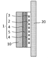
本発明の部材1は、表示装置10に静電気が流入することを防止する観点から、図5に示すようにフレキシブル基材2と接着層4との間に静電シールド層5をさらに設けてもよい。
静電シールド層5としては、静電気を防止することができるものであれば特に限定されず、当該技術分野において公知のものを用いることができる。静電シールド層5を構成する材料の例としては、Cu、Alなどの金属の他、カーボンなどが挙げられる。これらは、単独又は2種以上を組み合わせて用いることができる。
In order to prevent static electricity from flowing into the
The
静電シールド層5の厚さは、静電気を防止することができる範囲であれば特に限定されないが、一般に200μm以下、好ましくは5μm〜200μmである。静電シールド層5の厚さが200μm超過であると、部材1のフレキシブル性が損なわれることがある。また、静電シールド層5の厚さが5μm未満であると、静電シールド層5としての機能が十分に得られないことがある。
静電シールド層5の形成方法としては、特に限定されず、当該技術分野において公知の方法を用いることができる。例えば、静電シールド層5は、蒸着、貼着、塗布などの方法によって形成することができる。
The thickness of the
The method for forming the
また、フレキシブル基材2と静電シールド層5との間の接着性が十分に確保されない場合、図6に示すようにフレキシブル基材2と静電シールド層5との間に接着層4をさらに設けてもよい。また、接着層4は、図7に示すように、フレキシブル基材2と静電シールド層5との間及び静電シールド層5と表示装置10との間の両方に設けてもよい。
Further, when the adhesiveness between the
本発明の部材1の大きさは、特に限定されず、表示装置10の大きさに応じて適宜設定することができる。特に、表示装置10がフレキシブルディスプレイである場合、丸めた状態で運搬及び収納されていたフレキシブルディスプレイを広げて支持体20に取付けると、フレキシブルディスプレイに湾曲やうねりが生じ易いが、本発明の部材1の大きさを表示装置10の大きさと同じにすることより、フレキシブルディスプレイの湾曲やうねりを防止することが可能になる。
The size of the
本発明の部材1を用いることが可能な表示装置10としては、特に限定されず、液晶表示装置、有機EL表示装置などが挙げられる。
また、本発明の部材1により固定可能な支持体20としては、特に限定されず、壁、柱、窓などが挙げられる。
The
Moreover, the
上記のような構成を有する本発明の部材1は、外部電源から電圧(一般に100V以下)を印加することにより、静電吸着力が生じるため、表示装置10を静電吸着により支持体20に固定することができる。実際、本発明の部材1は、50V〜100Vの電圧の印加により、10g/cm2〜200g/cm2の荷重に耐えることができる。そのため、例えば、重さが2kgの55インチの表示装置10は0.25g/cm2程度の荷重に相当するところ、本発明の部材1を用いることにより、この表示装置10を支持体20に安定して固定することができる。
また、本発明の部材1は、外部電源からの電圧を遮断することにより、静電吸着力が低下するため、支持体20から表示装置10を容易に取り外すことができる。
The
Further, since the electrostatic attraction force of the
以上のように、本発明によれば、壁などの支持体20に傷や汚れをつけずに表示装置10を取付けることができると共に、取付けた際に表示装置10の湾曲やうねりを防止することができる部材1、及び当該部材1を有する表示装置10を提供することができる。
As described above, according to the present invention, the
1 部材、2 フレキシブル基材、3 電極、4 接着層、5 静電シールド層、10 表示装置、20 支持体。 1 member, 2 flexible base material, 3 electrode, 4 adhesive layer, 5 electrostatic shield layer, 10 display device, 20 support.
Claims (7)
フレキシブル基材と、
前記フレキシブル基材中又は前記フレキシブル基材上に設けられ且つ外部電源と電気的に接続可能である電極と、
前記表示装置と接する前記フレキシブル基材の第1面上に設けられた接着層と、
前記フレキシブル基材の前記第1面と前記接着層との間に設けられた静電シールド層と
を備え、
前記静電シールド層はCu,Al,カーボンのいずれか1つ以上からなり、5μmから200μmまでの範囲の厚さを有する単層であり、
前記電極に電圧が印加されたときに前記フレキシブル基材の第2面は前記支持体と接触しており、前記表示装置が静電吸着により該支持体に固定される
ことを特徴とする部材。 A member for fixing the display device to the support by electrostatic attraction,
A flexible substrate,
An electrode provided in or on the flexible substrate and electrically connectable to an external power source,
An adhesive layer provided on the first surface of the flexible substrate in contact with the display device;
An electrostatic shield layer provided between the first surface of the flexible substrate and the adhesive layer ,
The electrostatic shield layer is a single layer made of at least one of Cu, Al and carbon and having a thickness in the range of 5 μm to 200 μm,
The second surface of the flexible substrate is in contact with said support, member to which the display device is characterized in Rukoto fixed to the support by electrostatic adsorption when a voltage is applied to the electrode.
Priority Applications (1)
| Application Number | Priority Date | Filing Date | Title |
|---|---|---|---|
| JP2015239059A JP6735552B2 (en) | 2015-12-08 | 2015-12-08 | Member for fixing display device by electrostatic attraction and display device |
Applications Claiming Priority (1)
| Application Number | Priority Date | Filing Date | Title |
|---|---|---|---|
| JP2015239059A JP6735552B2 (en) | 2015-12-08 | 2015-12-08 | Member for fixing display device by electrostatic attraction and display device |
Publications (2)
| Publication Number | Publication Date |
|---|---|
| JP2017106993A JP2017106993A (en) | 2017-06-15 |
| JP6735552B2 true JP6735552B2 (en) | 2020-08-05 |
Family
ID=59059739
Family Applications (1)
| Application Number | Title | Priority Date | Filing Date |
|---|---|---|---|
| JP2015239059A Active JP6735552B2 (en) | 2015-12-08 | 2015-12-08 | Member for fixing display device by electrostatic attraction and display device |
Country Status (1)
| Country | Link |
|---|---|
| JP (1) | JP6735552B2 (en) |
Family Cites Families (6)
| Publication number | Priority date | Publication date | Assignee | Title |
|---|---|---|---|---|
| JPH0619347Y2 (en) * | 1988-03-28 | 1994-05-18 | オムロン株式会社 | Electrostatic adsorption device |
| CN1109482C (en) * | 1997-11-12 | 2003-05-21 | 三菱电机株式会社 | Electroluminescent body and structure for shielding same |
| JP4545889B2 (en) * | 2000-06-09 | 2010-09-15 | 富士通株式会社 | Circuit board, manufacturing method thereof, and semiconductor device |
| US7551419B2 (en) * | 2006-06-05 | 2009-06-23 | Sri International | Electroadhesion |
| JP5396170B2 (en) * | 2009-06-25 | 2014-01-22 | パナソニック株式会社 | Lighting system |
| US9130484B2 (en) * | 2011-10-19 | 2015-09-08 | Sri International | Vacuum augmented electroadhesive device |
-
2015
- 2015-12-08 JP JP2015239059A patent/JP6735552B2/en active Active
Also Published As
| Publication number | Publication date |
|---|---|
| JP2017106993A (en) | 2017-06-15 |
Similar Documents
| Publication | Publication Date | Title |
|---|---|---|
| KR102501909B1 (en) | Display apparatus | |
| CN106125846B (en) | Flexible screen support construction, flexible display screen module and mobile terminal | |
| JP6339996B2 (en) | Multilayer variable element and display device | |
| JP5500172B2 (en) | Electrostatic adsorption structure and manufacturing method thereof | |
| US20190371505A1 (en) | Support structure for supporting flexible display screen, and flexible display screen module | |
| CN104300828B (en) | A kind of friction generator | |
| US8982531B2 (en) | Additional force augmented electroadhesion | |
| US10236794B2 (en) | Hybrid power generating device | |
| WO2009071694A3 (en) | Electrowetting display having controlled fluid motion | |
| CN102116942A (en) | Thermal display component and thermal display device | |
| CN103889080B (en) | Heating resistance pad | |
| CN104658430A (en) | Flexible display device | |
| JP2008276035A (en) | Electronic equipment, display device and protective cover | |
| JP6296567B2 (en) | Variable element and display device | |
| US20190312528A1 (en) | Repulsive-attractive-force electrostatic actuator | |
| WO2012165250A1 (en) | Electrostatic adsorption body and electrostatic adsorption device using same | |
| JP6735552B2 (en) | Member for fixing display device by electrostatic attraction and display device | |
| KR101510801B1 (en) | Fine ciliary structure for electrostatic suction apparatus | |
| JP4808149B2 (en) | Electrostatic chuck | |
| KR102381748B1 (en) | Multilayer transformable device and display device comprising the same | |
| JP2007531036A5 (en) | ||
| TWI487971B (en) | Thermal display element and thermal display device | |
| JP2013061936A (en) | Micro structure substrates for sensor panels | |
| JP6647092B2 (en) | Electrostrictive element | |
| KR102725454B1 (en) | Display device and method for replacing the protective film |
Legal Events
| Date | Code | Title | Description |
|---|---|---|---|
| RD03 | Notification of appointment of power of attorney |
Free format text: JAPANESE INTERMEDIATE CODE: A7423 Effective date: 20180531 |
|
| RD04 | Notification of resignation of power of attorney |
Free format text: JAPANESE INTERMEDIATE CODE: A7424 Effective date: 20180612 |
|
| RD04 | Notification of resignation of power of attorney |
Free format text: JAPANESE INTERMEDIATE CODE: A7424 Effective date: 20180706 |
|
| A621 | Written request for application examination |
Free format text: JAPANESE INTERMEDIATE CODE: A621 Effective date: 20181029 |
|
| A131 | Notification of reasons for refusal |
Free format text: JAPANESE INTERMEDIATE CODE: A131 Effective date: 20190716 |
|
| A977 | Report on retrieval |
Free format text: JAPANESE INTERMEDIATE CODE: A971007 Effective date: 20190717 |
|
| A521 | Request for written amendment filed |
Free format text: JAPANESE INTERMEDIATE CODE: A523 Effective date: 20191016 |
|
| A131 | Notification of reasons for refusal |
Free format text: JAPANESE INTERMEDIATE CODE: A131 Effective date: 20200227 |
|
| A521 | Request for written amendment filed |
Free format text: JAPANESE INTERMEDIATE CODE: A523 Effective date: 20200527 |
|
| TRDD | Decision of grant or rejection written | ||
| A01 | Written decision to grant a patent or to grant a registration (utility model) |
Free format text: JAPANESE INTERMEDIATE CODE: A01 Effective date: 20200616 |
|
| A61 | First payment of annual fees (during grant procedure) |
Free format text: JAPANESE INTERMEDIATE CODE: A61 Effective date: 20200714 |
|
| R150 | Certificate of patent or registration of utility model |
Ref document number: 6735552 Country of ref document: JP Free format text: JAPANESE INTERMEDIATE CODE: R150 |
|
| R250 | Receipt of annual fees |
Free format text: JAPANESE INTERMEDIATE CODE: R250 |
|
| R250 | Receipt of annual fees |
Free format text: JAPANESE INTERMEDIATE CODE: R250 |
|
| R250 | Receipt of annual fees |
Free format text: JAPANESE INTERMEDIATE CODE: R250 |