JP6734546B2 - Information processing apparatus, control method thereof, and program - Google Patents
Information processing apparatus, control method thereof, and program Download PDFInfo
- Publication number
- JP6734546B2 JP6734546B2 JP2018108459A JP2018108459A JP6734546B2 JP 6734546 B2 JP6734546 B2 JP 6734546B2 JP 2018108459 A JP2018108459 A JP 2018108459A JP 2018108459 A JP2018108459 A JP 2018108459A JP 6734546 B2 JP6734546 B2 JP 6734546B2
- Authority
- JP
- Japan
- Prior art keywords
- area
- child
- subject
- facility
- parent
- Prior art date
- Legal status (The legal status is an assumption and is not a legal conclusion. Google has not performed a legal analysis and makes no representation as to the accuracy of the status listed.)
- Active
Links
Images


Description
本発明は、情報処理装置、及びその制御方法、プログラムに関し、特に、カメラによる撮影結果に基づいて、被写体が施設の外に出てしまうこと、又は被写体の置き去りに関する通知を行うための技術に関するものである。
The present invention relates to an information processing device, a control method therefor, and a program, and more particularly to a technique for notifying that a subject goes out of a facility or a subject is left on the basis of a shooting result by a camera. Is.
近年、ネットワークカメラを用いて、例えば、親(ユーザ)と子供(ユーザに引率された他のユーザ)がいる施設内で、子供が迷子になったことを検出して通知する仕組みが知られている。 2. Description of the Related Art In recent years, there has been known a mechanism of using a network camera to detect and notify that a child has become lost in a facility where, for example, a parent (user) and a child (another user led by the user) are present. There is.
特許文献1には、例えば、監視カメラで撮影された引率者の顔と、当該撮影された監視カメラとから特定された引率者がいる現在地と、監視カメラで撮影された子供の顔と、当該撮影された監視カメラとから特定された子供がいる現在地とが一定時間離れた状態であれば、その子供が迷子になったと判断して通知することが開示されている。
In
本発明の目的は、カメラによる撮影結果に基づいて、被写体が施設の外に出てしまうこと、又は被写体の置き去りに関する通知を行う仕組みを提供することである。
An object of the present invention is to provide a mechanism for notifying that a subject goes out of the facility or that the subject is left on the basis of the shooting result by the camera.
本発明は、カメラが各エリアを撮影して得られた各画像データに含まれる第1の被写体を特定して、前記第1の被写体が特定された画像データが撮影されたエリアを示すエリア情報を管理し、また前記第1の被写体に関係する被写体として登録された第2の被写体であって、カメラが各エリアを撮影して得られた各画像データに含まれる前記第2の被写体を特定して、前記第2の被写体が特定された画像データが撮影されたエリアを示すエリア情報を管理する管理手段と、前記管理手段により管理されたエリア情報を用いて、前記第1の被写体が施設の出口、又は出口付近エリアではない前記施設の他のエリアで撮影された状態で、前記第2の被写体が前記施設の出口、又は出口付近エリアで撮影されたかを判定する判定手段と、前記判定手段により、前記第1の被写体が前記施設の出口、又は出口付近エリアではない前記施設の他のエリアで撮影された状態で、前記第2の被写体が前記施設の出口、又は出口付近エリアで撮影されたと判定されたことを条件に、前記第2の被写体が前記施設の外に出てしまうことを知らせるための通知、又は、前記第1の被写体が前記施設に置き去りになっていることを知らせるための通知を行うように制御する通知制御手段と、を備えることを特徴とする。
According to the present invention, area information indicating an area in which image data in which the first object is specified is specified by specifying a first object included in each image data obtained by the camera capturing each area. And a second subject that is registered as a subject related to the first subject and that is included in each image data obtained by the camera capturing each area. Then, the first object is a facility using the area information managed by the managing unit that manages the area information indicating the area where the image data in which the second object is specified is captured. outlet, or in a state of being taken at other areas of the facility is not a outlet near the area, determining means for determining the second object is photographed by the facility outlet or outlets around the area, by the determination means, the first object of the facility outlet or in a state of being taken at other areas of the facility is not a outlet near the area, the second object of the facility outlet, or near the outlet, on condition that it is determined to have been taken with the area, the notification for notifying that the second object will get out of the facility, or in left behind the first object within the facility Notification control means for controlling so as to give a notification for notifying that the user is present.
また、本発明は、制御方法であって、管理手段が、カメラが各エリアを撮影して得られた各画像データに含まれる第1の被写体を特定して、前記第1の被写体が特定された画像データが撮影されたエリアを示すエリア情報を管理し、また前記第1の被写体に関係する被写体として登録された第2の被写体であって、カメラが各エリアを撮影して得られた各画像データに含まれる前記第2の被写体を特定して、前記第2の被写体が特定された画像データが撮影されたエリアを示すエリア情報を管理する管理工程と、判定手段が、前記管理工程により管理されたエリア情報を用いて、前記第1の被写体が施設の出口、又は出口付近エリアではない前記施設の他のエリアで撮影された状態で、前記第2の被写体が前記施設の出口、又は出口付近エリアで撮影されたかを判定する判定工程と、通知手段が、前記判定工程により、前記第1の被写体が前記施設の出口、又は出口付近エリアではない前記施設の他のエリアで撮影された状態で、前記第2の被写体が前記施設の出口、又は出口付近エリアで撮影されたと判定されたことを条件に、前記第2の被写体が前記施設の外に出てしまうことを知らせるための通知、又は、前記第1の被写体が前記施設に置き去りになっていることを知らせるための通知を行うように制御する通知制御工程と、を備えることを特徴とする。
Further, the present invention is the control method, wherein the management means specifies the first subject included in each image data obtained by the camera photographing each area, and the first subject is specified. The second object registered as a subject related to the first subject and managing the area information indicating the area in which the captured image data was captured, and each obtained by the camera capturing each area. A management step of specifying the second subject included in the image data and managing area information indicating an area in which the image data in which the second object is specified is photographed, and a determination means are performed by the management step. using a managed area information, the first subject of the facility outlet or in a state of being taken at other areas of the facility is not a outlet near the area, the second object of the facility outlet, or a determination step of determining taken with the outlet near the area, the notification means, by the determination step, the first subject of the facility outlet, or in other areas of not the facility at the exit near the area shooting state, the second object of the facility outlet, or on condition that it is determined to have been taken at the exit near the area, said second object will get out of the facility And a notification control step of controlling to perform a notification for notifying or a notification for notifying that the first subject is left at the facility .
また、本発明は、コンピュータを、上述の情報処理装置として機能させるためのプログラムを特徴とする。
Also, the present invention causes a computer, characterized by a program to function as the aforementioned information processing apparatus.
本発明によれば、カメラによる撮影結果に基づいて、被写体が施設の外に出てしまうこと、又は被写体の置き去りに関する通知を行うことができる。
According to the present invention, it is possible to give a notification regarding the subject going out of the facility or leaving the subject on the basis of the shooting result by the camera.
以下、図面を参照して、本発明の実施形態を詳細に説明する。 Hereinafter, embodiments of the present invention will be described in detail with reference to the drawings.
以下、本発明を適用した好適な実施形態を、添付図面を参照しながら詳細に説明する。 Hereinafter, a preferred embodiment to which the present invention is applied will be described in detail with reference to the accompanying drawings.
図1は、本発明の実施形態に係る情報処理システムの構成を示す図である。 FIG. 1 is a diagram showing a configuration of an information processing system according to an embodiment of the present invention.
図1に示す101は、サーバであり、有線、又は無線のネットワーク114を介して、各ネットワークカメラ103〜114と相互に通信可能に接続されている。
また、サーバ101は、無線のネットワークを介して携帯端末102と相互に通信可能に接続されている。
The
サーバ101は、ネットワークに接続されたカメラから当該カメラで撮影された画像データを、当該ネットワークを介して受信し、当該画像データを用いて迷子を特定して通知する情報処理装置の適用例である。
The
各ネットワークカメラ103〜114は、同一の施設内に設けられており、ネットワーク114に接続可能な撮像装置(カメラ)である。各ネットワークカメラ103〜114は、動画、及び/又は静止画を撮影可能なカメラである。以下、動画、及び/又は静止画を映像とも言う。
The
各ネットワークカメラ103〜114は、撮影された映像のデータを、サーバ101に送信する機能を備えている。
Each of the
ネットワークカメラ103〜106は、当該施設内のエリアAに設置されたカメラであり、各ネットワークカメラ103〜106は、それぞれ、ネットワークカメラ(個体)を識別するための識別情報をメモリに記憶している。
The
また、ネットワークカメラ107〜110は、当該施設内のエリアBに設置されたカメラであり、各ネットワークカメラ107〜110は、それぞれ、ネットワークカメラ(個体)を識別するための識別情報をメモリに記憶している。
The
また、ネットワークカメラ111〜114は、当該施設内のエリアCに設置されたカメラであり、各ネットワークカメラ111〜114は、それぞれ、ネットワークカメラ(個体)を識別するための識別情報をメモリに記憶している。エリアCは、出口エリア、又は出口近傍のエリアである。 The network cameras 111 to 114 are cameras installed in the area C of the facility, and each of the network cameras 111 to 114 stores identification information for identifying the network camera (individual) in the memory. ing. Area C is an exit area or an area near the exit.
各ネットワークカメラ103〜114は、被写体として、施設内にいる親115(保護者)、子供117を撮影する。親115(保護者)には、当該親(個人)を識別するための識別情報を示すカラーコードが付されている。たとえば、親115(保護者)の洋服に当該カラーコードのシールが付されている。また、当該親の子供117には、当該子供(個人)を識別するための識別情報を示すカラーコードが付されている。たとえば、子供117の洋服に当該カラーコードのシールが付されている。
Each of the
すなわち、各ネットワークカメラ103〜114は、被写体として、施設内にいる親115(保護者)のカラーコード、子供117のカラーコードを撮影する。
That is, each of the
ここでは、個人を識別するためのものとしてカラーコードを用いるようにしたが、カラーコード以外に、バーコードや、個人の顔の画像などを、個人を識別可能なものであれば、何でもよい。
携帯端末102は、親115が所持する携帯端末である。
Although the color code is used here for identifying the individual, any other code such as a barcode or an image of the face of the individual may be used as long as the individual can be identified.
The
図1では、各ネットワークカメラが設置されたエリアが、エリアA〜Cであることを説明したが、エリアA〜C以外に、エリアD〜Zにも、それぞれ同様にネットワークカメラが設けられている。 In FIG. 1, it has been described that the areas in which the network cameras are installed are areas A to C. However, in addition to the areas A to C, the area D to Z are also provided with network cameras in the same manner. ..
以下、図2を用いて、図1に示したサーバ101、携帯端末102に適用可能な情報処理装置のハードウェア構成について説明する。
The hardware configuration of the information processing apparatus applicable to the
図2は、図1に示したサーバ101、携帯端末102に適用可能な情報処理装置のハードウェア構成を示すブロック図である。
FIG. 2 is a block diagram showing a hardware configuration of an information processing apparatus applicable to the
図2において、201はCPUで、システムバス204に接続される各デバイスやコントローラを統括的に制御する。また、ROM203あるいは外部メモリ211には、CPU201の制御プログラムであるBIOS(Basic Input / Output System)やオペレーティングシステムプログラム(以下、OS)や、各サーバ或いは各PCの実行する機能を実現するために必要な後述する各種プログラム等が記憶されている。
In FIG. 2,
202はRAMで、CPU201の主メモリ、ワークエリア等として機能する。CPU201は、処理の実行に際して必要なプログラム等をROM203あるいは外部メモリ211からRAM202にロードして、該ロードしたプログラムを実行することで各種動作を実現するものである。
A
また、205は入力コントローラで、キーボード(KB)や不図示のマウス等のポインティングデバイス等の入力装置209からの入力を制御する。206はビデオコントローラで、液晶ディスプレイ等のディスプレイ装置210への表示を制御する。なお、210のディスプレイ装置は、タッチパネルになっており、ディスプレイ上の画面を押下されることにより操作することが可能な入力装置としても機能する。
An
207はメモリコントローラで、ブートプログラム,各種のアプリケーション,フォントデータ,ユーザファイル,編集ファイル,各種データ等を記憶する外部記憶装置(ハードディスク(HD))や、フレキシブルディスク(FD)、或いはPCMCIAカードスロットにアダプタを介して接続されるコンパクトフラッシュ(登録商標)メモリ等の外部メモリ211へのアクセスを制御する。
A
208は通信I/Fコントローラで、ネットワークを介して外部機器と接続・通信するものであり、ネットワークでの通信制御処理を実行する。例えば、TCP/IPを用いた通信等が可能である。
A communication I/
なお、CPU201は、例えばRAM202内の表示情報用領域へアウトラインフォントの展開(ラスタライズ)処理を実行することにより、ディスプレイ装置210上での表示を可能としている。また、CPU201は、ディスプレイ装置210上の不図示のマウスカーソル等でのユーザ指示を可能とする。
The
本発明を実現するための後述する各種プログラムは、外部メモリ211に記録されており、必要に応じてRAM202にロードされることによりCPU201によって実行されるものである。さらに、上記プログラムの実行時に用いられる定義ファイル及び各種情報テーブル等も、外部メモリ211に格納されており、これらについての詳細な説明も後述する。
<図3の説明>
Various programs to be described later for implementing the present invention are recorded in the
<Explanation of FIG. 3>
図3は、本発明の実施形態に係るサーバ101が実行する処理を示すフローチャートである。
FIG. 3 is a flowchart showing processing executed by the
ステップS301〜S305に示す各ステップの処理は、サーバ101の外部メモリ211に記録されているプログラムによる制御に従ってサーバ101のCPU201が実行する。
The processing of each step shown in steps S301 to S305 is executed by the
まず、各ネットワークカメラ(103〜114)は、撮影された映像のデータをサーバ101に逐次送信する。ここでの例は、撮影された映像のデータを、所定時間(例えば1分)間隔で送信する。
First, each of the network cameras (103 to 114) sequentially transmits the captured video data to the
また、ここで、各ネットワークカメラは、それぞれ、ネットワークカメラ(個体)を識別するための識別情報をメモリに記憶しているため、各ネットワークカメラは、映像データだけではなく、それぞれメモリに記憶している識別情報をサーバ101に送信する。
Further, here, each network camera stores identification information for identifying each network camera (individual) in the memory, so that each network camera stores not only video data but also each memory in the memory. The identification information that exists is transmitted to the
そして、サーバ101は、各ネットワークカメラから、各ネットワークカメラから映像データと、ネットワークカメラを識別するための識別情報を受信する(S301)。
Then, the
ここで映像データとは、静止画像データだけではなく、動画データも含まれる。動画データを構成するフレーム画像のデータを、静止画像データと同様に、後述する処理の対象とすることができる。 Here, the video data includes not only still image data but also moving image data. The data of the frame image forming the moving image data can be the target of the processing described below, as with the still image data.
ステップS301は、各カメラにより時間の経過と共に継続的に撮影された画像データ(映像データ)を当該各カメラから順次取得する取得手段の適用例である。 Step S301 is an application example of an acquisition unit that sequentially acquires, from each camera, image data (video data) continuously captured by each camera over time.
そして、サーバ101は、S301で受信した映像データを解析して、被写体を識別するための識別情報を取得する(S302)。例えば、サーバ101は、被写体に付されているカラーコードを、当該受信した映像データの中から特定し、当該特定されたカラーコードを読み取り解析することで、被写体を識別するための識別情報(カラーコードのID(個人を識別するための識別情報))を取得する。この識別情報を取得することで撮影されたユーザを特定することができる。
Then, the
すなわち、ステップS301は、取得手段により取得された画像データを解析することにより当該画像データに撮影されたユーザを特定するユーザ特定手段の適用例である。 That is, step S301 is an application example of the user identification unit that identifies the user photographed in the image data by analyzing the image data acquired by the acquisition unit.
次に、サーバ101は、ステップS301で受信したネットワークカメラの識別情報と、図11に示す対応テーブルとに従って、当該ネットワークカメラのエリア(被写体のいるエリア)を特定する。
<図11の説明>
Next, the
<Description of FIG. 11>
図11は、ネットワークカメラの識別情報と、当該ネットワークカメラが配置されているエリアのエリア名とが対応付けられた対応テーブルの一例を示す図である。 FIG. 11 is a diagram showing an example of a correspondence table in which the identification information of the network camera and the area name of the area in which the network camera is arranged are associated with each other.
図11のテーブルは、カメラが設置されているエリアを示すエリア情報(エリア名)をカメラごとに記憶手段(メモリ)に記憶されている。 In the table of FIG. 11, area information (area name) indicating the area where the camera is installed is stored in the storage unit (memory) for each camera.
図11に示す対応テーブルには、各ネットワークカメラの識別情報(001、002、003、・・・)と、それぞれのネットワークカメラが設置されているエリアのエリア名(エリアA、エリアB、エリアC、・・・)とが、それぞれ紐付けられてメモリに予め登録されている。 In the correspondence table shown in FIG. 11, the identification information (001, 002, 003,...) Of each network camera and the area name (area A, area B, area C) of the area where each network camera is installed. ,...) are associated with each other and registered in advance in the memory.
例えば、ネットワークカメラの識別情報が001のネットワークカメラが設置されているエリアは、エリアAであることを示している。 For example, the area in which the network camera whose network camera identification information is 001 is installed is Area A.
図3のステップS303では、ステップS301で受信したネットワークカメラの識別情報に対応して対応テーブル(図11)に記憶されているエリア名を取得することにより、当該ネットワークカメラが設置されているエリアを特定する。 In step S303 of FIG. 3, the area where the network camera is installed is acquired by acquiring the area name stored in the correspondence table (FIG. 11) corresponding to the identification information of the network camera received in step S301. Identify.
すなわち、ステップS303は、ステップS302でユーザが特定された画像データをステップS301で取得したカメラが設置されているエリアを示すエリア情報(図11)に基づき、ステップS302により特定されたユーザのいるエリアを特定するエリア特定手段の適用例である。 That is, step S303 is based on the area information (FIG. 11) indicating the area in which the camera, which has acquired the image data for which the user has been specified in step S302 and has been acquired in step S301, is located in the area where the user is specified in step S302. It is an application example of the area specifying means for specifying.
そして、サーバ101は、ここで特定されたエリアのエリア名と、ステップS302で取得した、被写体を識別するための識別情報(カラーコードのID(個人を識別するための識別情報))と、現在時刻(現在の時間)とをそれぞれ紐付けて、図8、又は図9に示す管理テーブルに登録する(S303)。
Then, the
ステップS303は、ステップS303により特定された、ステップS302により特定されたユーザ(親)のいるエリアを示すエリア情報、及び、ステップS303により特定された、ステップS302により特定された、当該ユーザに引率された他のユーザ(子供)のいるエリアを示すエリア情報を、当該画像データが前記カメラにより撮影された撮影時間ごとに、それぞれメモリ(記憶手段)に格納する格納手段の適用例である。
<図8、9の説明>
図8は、管理テーブルの一例を示す図である。
また、図9は、管理テーブルの他の例を示す図である。
In step S303, the area information indicating the area where the user (parent) identified in step S302 is located identified in step S303 and the user identified in step S302 identified in step S303 and led to by the user. It is an application example of a storage unit that stores area information indicating an area where another user (child) is present in a memory (storage unit) for each shooting time when the image data is shot by the camera.
<Explanation of FIGS. 8 and 9>
FIG. 8 is a diagram showing an example of the management table.
FIG. 9 is a diagram showing another example of the management table.
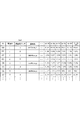
図8、及び図9に示す管理テーブルは、「ID」、「家族ID」、「保護者フラグ」、「通知先」、「時間」の項目が紐付けられて構成されている。 The management tables shown in FIGS. 8 and 9 are configured by associating items of “ID”, “family ID”, “guardian flag”, “notification destination”, and “time”.
「ID」は、被写体を識別するための識別情報(カラーコードのID)(例えば100)である。 The “ID” is identification information (color code ID) (for example, 100) for identifying the subject.
「家族ID」は、家族などのグループを識別するためのID(たとえば1)である。ここで同一の値が格納されている被写体(人)は、それぞれ同一の家族(グループ)であることを示している。 The "family ID" is an ID (for example, 1) for identifying a group such as a family. Here, the subjects (people) in which the same value is stored indicate that they are the same family (group).
「保護者フラグ」は、保護者であるか否かを示すフラグである。ここで、「1」は保護者であることを示し、「0」は保護者ではない者(例えば子供)であることを示している。 The “guardian flag” is a flag indicating whether or not the user is a guardian. Here, "1" indicates that the person is a guardian, and "0" indicates that the person is not a guardian (for example, a child).
「通知先」は、通知先の情報が格納される。ここで通知先とは、例として、保護者の携帯端末102に配信可能な電子メールのメールアドレス(たとえば、aaa@a.ne.jp)が格納されている。 The “notification destination” stores information of the notification destination. Here, as the notification destination, for example, a mail address of an electronic mail that can be delivered to the guardian's mobile terminal 102 (for example, aaa@a.ne.jp) is stored.
「時間」の項目には、所定時間(例えば1分)ごとの時間(・・・、「10:55」、「10:56」、「10:57」、「10:58」、「10:59」、「11:00」(現在時刻))が項目として設けられており、それぞれの時間に、「ID」(たとえば100)で識別される被写体がいたエリアのエリア名が、それぞれ格納されている。 The “time” item includes time (..., “10:55”, “10:56”, “10:57”, “10:58”, “10:” for each predetermined time (for example, 1 minute). 59” and “11:00” (current time)) are provided as items, and at each time, the area name of the area where the subject identified by the “ID” (for example, 100) was stored is stored. There is.
図8の「ID」が100の被写体(人)を例に説明すると、図8は、「ID」が100の被写体(人)が、「ID」が101の被写体(人)と同一の家族(グループ)であり、保護者であること(「ID」が101の被写体(人)は保護者ではない(子供))、通知先がaaa@a.ne.jpであること、「10:55」にエリアFにいたこと、「10:56」にエリアEにいたこと、「10:57」にエリアDにいたこと、「10:58」にエリアCにいたこと、「10:59」にエリアBにいたこと、「11:00」(現在時刻)にエリアAにいたことを示している。 In FIG. 8, the subject (person) whose “ID” is 100 will be described as an example. In FIG. 8, the subject (person) whose “ID” is 100 is the same family (person) as the subject (person) whose “ID” is 101. Group) and a guardian (the subject (person) whose “ID” is 101 is not a guardian (child)), and the notification destination is aaa@a. ne. jp, being in area F at "10:55", being in area E at "10:56", being in area D at "10:57", being in area C at "10:58". It means that it was in the area B at "10:59" and that it was in the area A at "11:00" (current time).
図8、又は図9に示す「ID」、「家族ID」、「保護者フラグ」、「通知先」、「時間」は、予め登録されており、ステップS303では、ステップS302で取得した「ID」(被写体を識別するための識別情報(カラーコードのID)と、現在時刻(現在の時間)とが紐付いた欄に、ステップS303で特定されたエリアのエリア名が登録される。 The “ID”, “family ID”, “guardian flag”, “notification destination”, and “time” shown in FIG. 8 or 9 are registered in advance, and in step S303, “ID” acquired in step S302. The area name of the area specified in step S303 is registered in the column in which the identification information (color code ID) for identifying the subject is associated with the current time (current time).
このようにして、サーバ101は、図8、又は図9に示す管理テーブルを所定期間(例えば1分)ごとに更新して登録することで、図8、又は図9に示す管理テーブルを生成する。
In this way, the
次に、サーバ101は、図4に示す迷子アラート処理、又は図5に示す迷子アラート処理を実行する(ステップS304)。更に、サーバ101は、ステップS304において、図6に示す出口付近アラート処理、及び図7に示す子供置き去りアラート処理を並行して処理する。
Next, the
すなわち、サーバ101は、図4に示す迷子アラート処理、又は図5に示す迷子アラート処理、図6に示す出口付近アラート処理、及び図7に示す子供置き去りアラート処理を並行して処理する。
That is, the
そして、サーバ101は、ステップS304の処理を実行すると、管理者(ユーザ)により終了の指示を受け付けた否かを判定し、終了指示を受け付けたと判定した場合には(YES)、処理を終了し、終了指示を受け付けていないと判定された場合には(NO)、処理をステップS301に戻す。
<図4の説明>
Then, when the
<Description of FIG. 4>
次に、図4を用いて、図3に示すステップS304で実行される迷子アラート処理の詳細処理について説明する。 Next, the detailed process of the lost child alert process executed in step S304 shown in FIG. 3 will be described with reference to FIG.
図4は、図3に示すステップS304で実行される迷子アラート処理の詳細処理を示すフローチャートの一例を示す図である。 FIG. 4 is a diagram showing an example of a flowchart showing detailed processing of the lost child alert processing executed in step S304 shown in FIG.
ステップS401〜S404に示す各ステップの処理は、サーバ101の外部メモリ211に記録されているプログラムによる制御に従ってサーバ101のCPU201が実行する。
図4に示すフローチャートは、同一の家族IDごとに繰り返し実行する。
The processing of each step shown in steps S401 to S404 is executed by the
The flowchart shown in FIG. 4 is repeatedly executed for each same family ID.
まず、サーバ101は、管理テーブル(図8、又は図9)の上部の先頭レコードから順番に、同一の家族IDごとに、図4に示す処理を実行する。
First, the
まず、サーバ101は、管理テーブル(図8又は図9)から、家族IDが同一のレコードのうち、「ID」、「家族ID」、「保護者フラグ」、「通知先」の各データと、現在時刻のエリア名と、現在時刻から所定時間分(ここでは例えば6秒分)のエリア名とを取得する(ステップS401)。
例えば、「家族ID」が1のレコードを例に説明する。
First, the
For example, a record in which the "family ID" is 1 will be described as an example.
ステップS401では、「ID」が100と101のレコードのうち、「ID」が100の情報(「ID」が100、「家族ID」が1、「保護者フラグ」が1、「通知先」がaaa@a.ne.jp、「10:55」のときにいたエリア:エリアF、「10:56」のときにいたエリア:エリアE、「10:57」のときにいたエリア:エリアD、「10:58」のときにいたエリア:エリアC、「10:59」のときにいたエリア:エリアB、「11:00」のときにいたエリア:エリアA)と、「ID」が101の情報(「ID」が101、「家族ID」が1、「保護者フラグ」が0、「通知先」はNULL、「10:55」のときにいたエリア:エリアF、「10:56」のときにいたエリア:エリアE、「10:57」のときにいたエリア:エリアD、「10:58」のときにいたエリア:エリアC、「10:59」のときにいたエリア:エリアB、「11:00」のエリアB)と、を取得する。 In step S401, of the records having "ID" of 100 and 101, information having "ID" of 100 ("ID" is 100, "family ID" is 1, "guardian flag" is 1, and "notification destination" is aaa@a.ne.jp, the area when "10:55" was: area F, the area when "10:56" was area E, the area when "10:57" was area: D, Area: Area C when "10:58", Area: Area B when "10:59", Area: Area A when "11:00", and "ID" of 101 Information (“ID” is 101, “Family ID” is 1, “Guardian flag” is 0, “Notification destination” is NULL, Area: Area F when “10:55”: “10:56” Area that was present: area E, area that was present at "10:57": area D, area that was present at "10:58": area C, area that was present at "10:59": area B, Area B) of "11:00" is acquired.
そして、サーバ101は、ステップS401で取得した親子の現在時刻のエリア名に従って、現在の親子がいるエリアが異なるか否かを判定する(S402)。
Then, the
例えば、保護者フラグが1と設定されている現在時刻(11:00)のエリア名と、保護者フラグが0と設定されている現在時刻(11:00)のエリア名を比較して、同一であれば、親子が同じエリアにいると判定し(NO)、一方、同一でなければ、親子が同じエリアにいない(現在の親子がいるエリアが異なる)と判定する(YES)。 For example, the area name at the current time (11:00) in which the guardian flag is set to 1 and the area name at the current time (11:00) in which the parent flag is set to 0 are compared and are the same. If so, it is determined that the parent and child are in the same area (NO). On the other hand, if they are not the same, it is determined that the parent and child are not in the same area (the areas where the current parent and child are different are different) (YES).
サーバ101は、ステップS402において、親子が同じエリアにいると判定された場合(NO)には、処理をステップS305に移行し、親子が異なるエリアにいると判定された場合(YES)には、処理をステップS403に移行する。
If it is determined in step S402 that the parent and child are in the same area (NO), the
そして、サーバ101は、ステップS401で取得した、現在時刻から所定時間分(ここでは例えば6秒分)の親子のエリア名のうち、直近の過去の所定期間(たとえば2秒)分の親子のいるエリアが異なるかを判定する(ステップS403)。
Then, the
例えば、ステップS403において、保護者フラグが1と設定されている時刻(10:58)のエリア名と、保護者フラグが0と設定されている時刻(10:58)のエリア名とが一致しており、かつ、保護者フラグが1と設定されている時刻(10:59)のエリア名と、保護者フラグが0と設定されている時刻(10:59)のエリア名とが一致しているか、を判定する。 For example, in step S403, the area name at the time (10:58) when the parent flag is set to 1 matches the area name at the time (10:58) when the parent flag is set to 0. And the area name at the time (10:59) when the parent flag is set to 1 matches the area name at the time (10:59) when the parent flag is set to 0. Determine whether or not.
サーバ101は、保護者フラグが1と設定されている時刻(10:58)のエリア名と、保護者フラグが0と設定されている時刻(10:58)のエリア名とが一致しており、かつ、保護者フラグが1と設定されている時刻(10:59)のエリア名と、保護者フラグが0と設定されている時刻(10:59)のエリア名とが一致していると判定された場合には、直近の過去の所定期間(たとえば2秒)の親子のいるエリアが異ならない(親子のいるエリアが同じ)(NO)と判定し、一方、保護者フラグが1と設定されている時刻(10:58)のエリア名と、保護者フラグが0と設定されている時刻(10:58)のエリア名とが一致していない、又は、保護者フラグが1と設定されている時刻(10:59)のエリア名と、保護者フラグが0と設定されている時刻(10:59)のエリア名とが一致していないと判定された場合には、直近の過去の所定期間(たとえば2秒)の親子のいるエリアが異なる(YES)と判定する。
In the
ステップS402、ステップS403は、ステップS303(エリア特定手段)により特定されたエリア情報がメモリ(記憶手段)に格納された最後の撮影時間(例えば、図8の11:00(現在))から過去の所定時間内における、ステップS303(格納手段)により格納された親(ユーザ)のいるエリアを示すエリア情報(エリア名)と、子供(他のユーザ)のいるエリアを示すエリア情報(エリア名)とがそれぞれ異なるか否かを判定する判定手段の適用例である。 Steps S402 and S403 are past from the last photographing time (for example, 11:00 (current) in FIG. 8) when the area information specified by step S303 (area specifying means) is stored in the memory (storage means). Area information (area name) indicating the area where the parent (user) is stored and area information (area name) indicating the area where the child (other user) is stored, stored in step S303 (storage means) within a predetermined time. It is an application example of the determination means for determining whether or not each is different.
サーバ101は、ステップS403で、直近の過去の所定期間(たとえば2秒)の親子のエリアが異なる(YES)と判定された場合には、子供が迷子である旨を、同一家族IDで保護者フラグが1が設定されている通知先(例えば、aaa@a.ne.jp)に通知する。
ここで通知される内容の例を、図10の1001に示す。
If the
An example of the content notified here is shown in 1001 of FIG.
例えば、図8の家族IDが1の場合、保護者(親)(保護者フラグが1)と子供(保護者フラグが0)の移動経路が、10:55から10:59までは同じであるが、11:00では、親子のいるエリアが異なる。 For example, when the family ID in FIG. 8 is 1, the travel routes of the guardian (parent) (guardian flag is 1) and the child (guardian flag is 0) are the same from 10:55 to 10:59. However, at 11:00, the areas with parents and children are different.
このように現在の時刻で親と子のいるエリアが異なる場合であっても、現在時刻から直近の所定期間内は、親と子がいるエリアが同じであるため、S403でNOと判定され、親に子供が迷子である通知が行われない。 Even if the area where the parent and the child are different at the current time in this way, since the area where the parent and the child are the same within the predetermined period immediately after the current time, it is determined as NO in S403, Parents are not notified that their child is lost.
それゆえ、例えば、管理テーブルの更新のタイミングで、たまたま、親が子供とは異なるエリアに移動した場合であっても、迷子であるとの誤判定することを低減させることが可能となる。 Therefore, for example, even when the parent happens to move to an area different from that of the child at the timing of updating the management table, it is possible to reduce erroneous determination that the child is a lost child.
このように、図4に示す処理を行うことにより、例えば、障害物によりカラーコードを一時的に認識出来なかった場合や、親子が一緒に移動しているが、たまたま、親と子とがそれぞれ異なるエリアにいると認識された場合であっても、迷子の誤判定を減らすことができる。 By performing the process shown in FIG. 4 in this way, for example, when the color code cannot be recognized temporarily due to an obstacle, or the parent and the child are moving together, it happens that the parent and the child respectively Even if it is recognized that the user is in a different area, it is possible to reduce the false determination of a lost child.
また、例えば、図8の家族ID4の場合のように、現在、たまたま、カラーコードが障害物等により撮像できず、親又は子のいるエリアが認識できなかった場合(現在いるエリアがNULLの場合)であっても、親に子供が迷子である通知を行わないため、迷子であるとの誤判定することを低減させることが可能となる。
Further, for example, as in the case of the
このように、図8に示す管理テーブルを例に、図4に示す迷子アラート処理を実行した場合、家族IDが1、4については、親に子供が迷子である通知を行わないが、家族IDが2、3の場合については、親に子供が迷子である通知を行うこととなる。
In this way, when the lost child alert processing shown in FIG. 4 is executed using the management table shown in FIG. 8 as an example, the
ただ、子供の歩く速度が親の歩く速度よりも遅く、たまたま、子供がいるエリアよりも先のエリアに親がいた場合、図8に示す管理テーブルの家族IDが2の場合のように、親子のエリアが検出されてしまうことがある。 However, if the walking speed of the child is slower than the walking speed of the parent and it happens that there is a parent in the area ahead of the area where the child is, as in the case where the family ID in the management table shown in FIG. Area may be detected.
すなわち、図4の処理の場合、親子の経路は同一であるが、各時刻の親子のいるエリアが異なる場合でも、親に子供が迷子である通知を行うこととなる。このような誤判定を低減させるための仕組みを、図5を用いて、後で説明する。
<図10の説明>
図10は、サーバ101が通知する通知内容の一例を示す図である。
That is, in the case of the process of FIG. 4, even if the parent-child route is the same, the parent is notified that the child is lost even if the parent-child area at each time is different. A mechanism for reducing such erroneous determination will be described later with reference to FIG.
<Description of FIG. 10>
FIG. 10 is a diagram showing an example of notification contents notified by the
図10の1001では、子供が迷子である旨と共に、子供が現在撮影されたネットワークカメラの位置を、子供がいる現在地として通知する。 In 1001 of FIG. 10, together with the fact that the child is lost, the position of the network camera where the child is currently photographed is notified as the current location of the child.
また、サーバ101は、ステップS403で、直近の過去の所定期間(たとえば2秒)の親子のエリアが一致していると判定された場合には(NO)、処理ステップS305に移行する。
If the
サーバ101は、図4に示す迷子アラート処理の代わりに、図5に示す迷子アラート処理を実行することもできる。
<図5の説明>
The
<Explanation of FIG. 5>
次に、図5を用いて、図3に示すステップS304で実行される迷子アラート処理の詳細処理について説明する。 Next, the detailed process of the lost child alert process executed in step S304 shown in FIG. 3 will be described with reference to FIG.
図5は、図3に示すステップS304で実行される迷子アラート処理の詳細処理を示すフローチャートの一例を示す図である。 FIG. 5 is a diagram showing an example of a flowchart showing detailed processing of the lost child alert processing executed in step S304 shown in FIG.
図5に示すステップS401〜S404、S405、S406に示す各ステップの処理は、サーバ101の外部メモリ211に記録されているプログラムによる制御に従ってサーバ101のCPU201が実行する。
図5に示すフローチャートは、同一の家族IDごとに繰り返し実行する。
The processing of each step shown in steps S401 to S404, S405, and S406 shown in FIG. 5 is executed by the
The flowchart shown in FIG. 5 is repeatedly executed for each same family ID.
まず、サーバ101は、管理テーブル(図8、又は図9)の上部の先頭レコードから順番に、同一の家族IDごとに、図5に示す処理を実行する。
図5では、図4と同じ処理を行うステップについては、同一の符号を付している。
そのため、図5では、図4と異なる処理についてのみ説明する。
First, the
In FIG. 5, steps that perform the same processing as in FIG. 4 are assigned the same reference numerals.
Therefore, in FIG. 5, only processes different from those in FIG. 4 will be described.
図5に示すフローチャートは、図4のフローチャートに、ステップS405とステップS406が追加されている点のみが異なる。 The flowchart shown in FIG. 5 differs from the flowchart of FIG. 4 only in that step S405 and step S406 are added.
サーバ101は、ステップS403において、直近の過去の所定期間(たとえば2秒)の親子のいるエリアが異なると判定された場合(ステップS403:YES)、ステップS401で取得された、親子の各時間にいたエリア名から、親子それぞれの所定時間(例えば5秒)分の移動経路を特定する(ステップS405)。
When it is determined in step S403 that the areas where the parent and child are in the latest past predetermined period (for example, 2 seconds) are different in step S403 (step S403: YES), the
ステップS405は、ステップS303(格納手段)により格納された親(ユーザ)のいるエリアを示すエリア情報(エリア名)と、子供(他のユーザ)のいるエリアを示すエリア情報(エリア名)と(図8、又は図9)に従って、ステップS303(エリア特定手段)により特定されたエリア情報(エリア名)がステップS304(格納手段)によりメモリ(記憶手段)に格納された最後の撮影時間(例えば図8の11:00(現在))から過去の所定時間内における、親(ユーザ)の移動経路と、子供(他のユーザ)の移動経路とを特定する特定手段の適用例である。
ここで、ステップS405の具体例について、説明する。
In step S405, area information (area name) indicating the area in which the parent (user) is stored and area information (area name) in which the child (other user) is stored, stored in step S303 (storage unit), ( The area information (area name) specified by step S303 (area specifying means) according to FIG. 8 or FIG. 9) is stored in the memory (storage means) by step S304 (storage means) at the last photographing time (for example, FIG. 8 is an application example of a specifying unit that specifies a moving path of a parent (user) and a moving path of a child (other user) within a predetermined time in the past from 11:00 (current) of 8).
Here, a specific example of step S405 will be described.
例えば、図8に示す家族IDが2のレコード(カラーコードのIDが102のレコードと、カラーコードのIDが103のレコード)をステップS401で取得して処理対象としている場合、カラーコードのIDが102の被写体(人)は、エリアF(10:56)、エリアE(10:57)、エリアD(10:58)、エリアC(10:59)、エリアB(11:00)の移動経路でエリアを移動しており、カラーコードのIDが103の被写体(人)は、エリアF(10:55)、エリアE(10:56)、エリアD(10:57)、エリアC(10:58)、エリアB(10:59)の移動経路でエリアを移動している。すなわち、1分ずれて、カラーコードのIDが102の被写体(人:親)と、カラーコードのIDが103の被写体(人:子)が同じ移動経路で移動している。
For example, when the record having the
このように、ステップS405では、ステップS401で取得された、親子の各時間にいたエリア名から、親子それぞれの所定時間(例えば5秒)分の移動経路を特定することができる。 In this way, in step S405, it is possible to specify the movement route for each parent and child for a predetermined time (for example, 5 seconds) from the area name acquired in step S401 at each time of the parent and child.
次に、サーバ101は、ステップS405で特定された、親子の所定時間(たとえば5秒)分の移動経路が異なるか否かを判定し(ステップS406)、異なると判定された場合には(YES)、子供が迷子である旨を通知する(ステップS404)。一方、親子の所定時間(たとえば5秒)分の移動経路が同じと判定された場合には(NO)、子供が迷子である旨を通知することなく、処理をステップS305に移行する。ステップS404は、図4のステップS404と同じ処理であるため、ここでは説明を省略する。
Next, the
ステップS406は、ステップS405(特定手段)により特定された親(ユーザ)の移動経路と、子供(他のユーザ)の移動経路とが異なるか否かを判定する移動経路判定手段の適用例である。 Step S406 is an application example of the movement route determination unit that determines whether or not the movement route of the parent (user) identified by Step S405 (identification unit) and the movement route of the child (other user) are different. ..
ステップS404は、ステップS402、S403(判定手段)により、親(ユーザ)のいるエリアを示すエリア情報(エリア名)と子供(他のユーザ)のいるエリアを示すエリア情報(エリア名)とがそれぞれ異なると判定され、かつ、ステップS406(移動経路判定手段)により、親(ユーザ)の移動経路と、子供(他のユーザ)の移動経路とが異なると判定された場合に(ステップS406:YES)、子供(他のユーザ)が迷子である旨を親又は管理者が操作する端末に通知するようにサーバ101は制御する(制御手段)。
In step S404, the area information (area name) indicating the area where the parent (user) is present and the area information (area name) indicating the area where the child (other user) is present are respectively obtained by steps S402 and S403 (determining means). When it is determined that they are different, and it is determined by step S406 (moving route determination means) that the moving route of the parent (user) and the moving route of the child (other user) are different (step S406: YES). The
また、ステップS402、ステップS403(判定手段)により、親(ユーザ)のいるエリアを示すエリア情報(エリア名)と子供(他のユーザ)のいるエリアを示すエリア情報(エリア名)とが一致する(ステップS402:NO、ステップS403:NO)、又は、ステップS402、S403(判定手段)により、親(ユーザ)のいるエリアを示すエリア情報(エリア名)と子供(他のユーザ)のいるエリアを示すエリア情報(エリア名)とがそれぞれ異なると判定された場合であっても、ステップS406(移動経路判定手段)により、親(ユーザ)の移動経路と、子供(他のユーザ)の移動経路とが一致すると判定された場合には(ステップS406:NO)、子供(他のユーザ)が迷子である旨を通知しないようにサーバ101は制御する(制御手段)。
Further, in step S402 and step S403 (determination means), the area information (area name) indicating the area where the parent (user) is present matches the area information (area name) indicating the area where the child (other user) is present. (Step S402: NO, Step S403: NO) or Steps S402 and S403 (determining means) are used to determine the area information (area name) indicating the area where the parent (user) is and the area where the child (other user) is. Even when it is determined that the area information (area name) indicated is different from each other, the movement route of the parent (user) and the movement route of the child (other user) are determined by step S406 (movement route determination means). When it is determined that the two match (step S406: NO), the
また、サーバ101は、テップ404では、子供(他のユーザ)が迷子である旨と共に、当該他のユーザのエリア情報(エリア名)がステップS303(格納手段)によりメモリ(記憶手段)に格納された最後の撮影時間(例えば図9の11:00(現在))における当該他のユーザ(子供)のエリア情報(エリア名)を通知する。
In addition, in
このように、図5に示す処理により、図4に示す処理による上述の効果に加えて、実際は親子が一緒に移動しているが、たまたま、親と子とがそれぞれ異なるエリアにいると連続して認識された場合であっても、迷子の誤判定を減らすことが可能となるという効果を奏することができる。
<図6の説明>
As described above, in addition to the above-described effects of the process shown in FIG. 4, the process shown in FIG. 5 actually causes the parent and child to move together, but happens to be continuous when the parent and the child are in different areas. Even if it is recognized as such, it is possible to reduce an erroneous determination of a lost child.
<Description of FIG. 6>
次に、図6を用いて、図3に示すステップS304で実行される出口付近アラート処理の詳細処理について説明する。 Next, detailed processing of the exit vicinity alert processing executed in step S304 shown in FIG. 3 will be described with reference to FIG.
図6は、図3に示すステップS304で実行される出口付近アラート処理の詳細処理を示すフローチャートの一例を示す図である。 FIG. 6 is a diagram showing an example of a flowchart showing detailed processing of the exit vicinity alert processing executed in step S304 shown in FIG.
ステップS601〜S609に示す各ステップの処理は、サーバ101の外部メモリ211に記録されているプログラムによる制御に従ってサーバ101のCPU201が実行する。
図6に示すフローチャートは、同一の家族IDごとに繰り返し実行する。
The processing of each step shown in steps S601 to S609 is executed by the
The flowchart shown in FIG. 6 is repeatedly executed for each same family ID.
まず、サーバ101は、管理テーブル(図8、又は図9)の上部の先頭レコードから順番に、同一の家族IDごとに、図6に示す処理を実行する。
First, the
まず、サーバ101は、ステップS401と同様に、管理テーブル(図8又は図9)から、家族IDが同一のレコードのうち、「ID」、「家族ID」、「保護者フラグ」、「通知先」の各データと、現在時刻のエリア名と、現在時刻から所定時間分(ここでは例えば6秒分)のエリア名とを取得する(ステップS601)。
First, as in step S401, the
そして、サーバ101は、ステップS601で取得した親子の現在時刻のエリア名に従って、現在の親子がいるエリアが異なるか否かを判定する(S602)。
Then, the
ステップS602の処理は、上述したステップS402と同様の処理であるため、ここでは具体例を用いた説明は、省略する。 Since the process of step S602 is the same as the process of step S402 described above, description using a specific example is omitted here.
サーバ101は、ステップS602において、親子が同じエリアにいると判定された場合(NO)には、処理をステップS305に移行し、親子が異なるエリアにいると判定された場合(YES)には、処理をステップS603に移行する。
If it is determined in step S602 that the parent and child are in the same area (NO), the
そして、サーバ101は、ステップS601で取得した、現在時刻から所定時間分(ここでは例えば6秒分)の親子のエリア名のうち、直近の過去の所定期間(たとえば2秒)分の親子のいるエリアが異なるかを判定する(ステップS603)。
Then, the
ステップS603の処理も、上述したステップS403と同様の処理であるため、ここでは具体例を用いた説明は省略する。 Since the process of step S603 is the same as the process of step S403 described above, the description using a specific example is omitted here.
そして、サーバ101は、ステップS603で、直近の過去の所定期間(たとえば2秒)の親子のエリアが異なると判定された場合には(YES)、処理をステップS604に移行する。一方、直近の過去の所定期間(たとえば2秒)の親子のエリアが異ならない(同じである)と判定された場合には(NO)、処理をステップS608に移行する。
If the
サーバ101は、ステップS603において、直近の過去の所定期間(たとえば2秒)の親子のいるエリアが異なると判定された場合(ステップS603:YES)、ステップS601で取得された、親子の各時間にいたエリア名から、親子それぞれの所定時間(例えば5秒)分の移動経路を特定する(ステップS604)。
When it is determined in step S603 that the areas where the parent and child are in the latest past predetermined period (for example, 2 seconds) are different in step S603 (step S603: YES), the
ステップS604も、上述したステップS405と同様の処理であるため、ここでは具体例を用いた説明は省略する。 Since step S604 is the same process as step S405 described above, description using a specific example is omitted here.
そして、サーバ101は、ステップS604で特定された、親子の所定時間(たとえば5秒)分の移動経路が異なるか否かを判定し(ステップS605)、異なると判定された場合には(YES)、処理をステップS606に移行し、一方、親子の所定時間(たとえば5秒)分の移動経路が同じと判定された場合には(NO)、処理をステップS608に移行する。
Then, the
ステップS605は、図5のステップS406と同じ処理であるため、ここでは具体例を用いた説明は省略する。 Since step S605 is the same process as step S406 in FIG. 5, description using a specific example is omitted here.
サーバ101は、ステップS606において、ステップS601で取得したエリア名から、現在、親のいるエリアが出口エリア、又は出口付近エリアではなく、子供が出口エリア、又は出口付近エリアにいるか否かを判定する。
In step S606, the
例えば、図9の管理テーブル900に示す家族IDが3のレコード(IDが104のレコードと、IDが105のレコード)が処理対象の場合、ステップS606の判定処理が行われる。この場合、11:00(現在)、親(IDが104である被写体)は、エリアAにおり、子(IDが105である被写体)は、エリアC(出口エリア、又は出口付近エリア)にいることが分かる。 For example, when the record having the family ID of 3 (the record having the ID of 104 and the record having the ID of 105) shown in the management table 900 of FIG. 9 is the processing target, the determination process of step S606 is performed. In this case, at 11:00 (current), the parent (subject with ID 104) is in area A, and the child (subject with ID 105) is in area C (exit area or near exit area). I understand.
そのため、図9の管理テーブル900に示す家族IDが3のレコードの場合、ステップS606において、親のいるエリアが出口エリア、又は出口付近エリアではなく、子供が出口エリア、又は出口付近エリアにいる(ステップS606:YES)と判定される。 Therefore, in the case where the family ID shown in the management table 900 of FIG. 9 is a record of 3, in step S606, the area where the parents are is not the exit area or the exit vicinity area, but the child is in the exit area or the exit vicinity area ( Step S606: YES).
サーバ101は、ステップS601で取得したエリア名から、現在、親のいるエリアが出口エリア、又は出口付近エリアではなく、子供が出口エリア、又は出口付近エリアにいると判定された場合(ステップS606:YES)、子供が迷子である旨、及び子供が施設外に出てしまうおそれがある旨を、現在処理対象のレコードの保護者フラグに1が設定されたレコードの通知先に、通知する(ステップS607)。
ステップS607で通知される内容の例を、図10の1002に示す。
When the
An example of the content notified in step S607 is shown in 1002 of FIG.
そして、サーバ101は、ステップS607の処理を実行すると、処理をステップS305に移行する。
Then, when the
サーバ101は、ステップS606において、ステップS601で取得したエリア名から、現在、親のいるエリアが出口エリア、又は出口付近エリアである、又は子供が出口エリア、又は出口付近エリアにいないと判定された場合(ステップS606:NO)、処理をステップS305に移行する。
In step S606, the
サーバ101は、ステップS608において、ステップS601で取得したエリア名から、現在、親のいるエリアが出口エリア、又は出口付近エリアではなく、子供が出口エリア、又は出口付近エリアにいるか否かを判定する。
In step S608, the
ステップS608の処理も、ステップS606の処理と同様であるため、ここでは、具体例を用いた説明を省略する。 Since the process of step S608 is also similar to the process of step S606, description using a specific example is omitted here.
そして、サーバ101は、ステップS608において、ステップS601で取得したエリア名から、現在、親のいるエリアが出口エリア、又は出口付近エリアではなく、子供が出口エリア、又は出口付近エリアにいると判定された場合には(YES)、子供が施設外に出てしまうおそれがある旨を、現在処理対象のレコードの保護者フラグに1が設定されたレコードの通知先に、通知する(ステップS609)。
Then, in step S<b>608, the
ステップS609で通知される内容の例を、図10の1003に示す。そして、サーバ101は、ステップS607の処理を実行すると、処理をステップS305に移行する。
An example of the content notified in step S609 is shown in 1003 of FIG. Then, when the
また、サーバ101は、ステップS608において、ステップS601で取得したエリア名から、現在、親のいるエリアが出口エリア、又は出口付近エリアである、又は、子供が出口エリア、又は出口付近エリアにはいないと判定された場合には(NO)、処理をステップS305に移行する。
In addition, in step S608, the
ステップS606、ステップS608は、図8、又は図9のテーブルの最後の撮影時間(例えば、図8、図9の11:00(現在))における、親(ユーザ)のエリア情報(エリア名)が出口エリアまたは出口付近エリアを示すエリア情報(エリアC)ではなく、子供(他のユーザ)のエリア情報(エリア名)が出口エリアまたは出口付近エリアを示すエリア情報(エリアC)であるか否かを判定する出口判定手段の適用例である。 In steps S606 and S608, the area information (area name) of the parent (user) at the last shooting time (for example, 11:00 (current) in FIGS. 8 and 9) in the table of FIG. 8 or 9 is displayed. Whether or not the area information (area name) of the child (other user) is the area information (area C) indicating the exit area or the area near the exit, not the area information (area C) indicating the exit area or the area near the exit. It is an application example of the exit determination means for determining.
そして、サーバ101は、ステップS607、ステップS609では、他のユーザが施設外に出てしまう旨を通知する。
Then, in step S607 and step S609, the
図6に示す処理を実行することにより、親のいるエリアが出口エリアではなく、かつ、子供のいるエリアが出口エリアある場合、保護者にアラートを通知するため、例えば、子供が施設外に出てしまい、カラーコードによる捜索が出来なくなってしまうことを防止することができる。 By executing the process shown in FIG. 6, if the area where the parent is not the exit area and the area where the child is is the exit area, an alert is sent to the guardian. For example, the child goes out of the facility. It is possible to prevent the search by the color code from being disabled.
さらに、子供が迷子の状態で、出口エリアに来てしまった場合(S602でYES、S603でYES、S605でYES、S606でYESと判定された場合)には、ステップS607で、子供が迷子である旨と子供が施設外に出てしまう旨を保護者に通知するため、親が施設内にいる状態で、迷子の子供が施設外に出てしまい、カラーコードによる捜索が出来なくなってしまうことを防止することができる。 Furthermore, if the child has come to the exit area in a lost state (YES in S602, YES in S603, YES in S605, YES in S606), the child is lost in step S607. In order to notify the guardian that there is one and that the child will go out of the facility, the lost child will go out of the facility while the parent is inside the facility, making it impossible to search by color code Can be prevented.
また、親子が一緒に移動しているが、たまたま、親と子とがそれぞれ異なるエリアにいると認識された場合(S604、S605でNO)、S607で子供が迷子である旨の通知を行わないので、迷子の誤判定を防止することができる。 If the parent and the child are moving together, but it happens that the parent and the child are in different areas (NO in S604 and S605), the notification that the child is lost is not issued in S607. Therefore, it is possible to prevent erroneous determination of a lost child.
また、親子が一緒に移動しているが、たまたま、親と子とがそれぞれ異なるエリアにいると認識された場合でも(S604、S605でNO)、ステップS608で、親は出口エリアにはいないが子供が出口エリアにいると判定された場合には(YES)、子供が施設外に出てしまう旨を通知するため、例えば、子供が迷子の状態ではなかったが、子供がいきなり出口に向かって走って親から離れて、(親が子供の位置を把握できず、)子供が出口から施設外に出そうになった場合でも、子供が出口エリアにいることを親が把握でき、施設外に子供が出てしまうことを防止することができる。
<図7の説明>
Further, even if the parent and the child are moving together, but it happens that it is recognized that the parent and the child are in different areas (NO in S604 and S605), the parent is not in the exit area in step S608. If it is determined that the child is in the exit area (YES), in order to notify that the child will leave the facility, for example, the child was not lost, but the child suddenly headed for the exit. Even if the child runs away from the parent and the child tries to get out of the facility from the exit (because the parent cannot grasp the child's position), the parent can know that the child is in the exit area and go outside the facility. It is possible to prevent children from leaving.
<Description of FIG. 7>
次に、図7を用いて、図3に示すステップS304で実行される子供置き去りアラート処理の詳細処理について説明する。 Next, the detailed processing of the child leaving alert processing executed in step S304 shown in FIG. 3 will be described with reference to FIG.
図7は、図3に示すステップS304で実行される子供置き去りアラート処理の詳細処理を示すフローチャートの一例を示す図である。 FIG. 7 is a diagram showing an example of a flowchart showing detailed processing of the child leaving alert processing executed in step S304 shown in FIG.
ステップS701〜S707に示す各ステップの処理は、サーバ101の外部メモリ211に記録されているプログラムによる制御に従ってサーバ101のCPU201が実行する。
図7に示すフローチャートは、同一の家族IDごとに繰り返し実行する。
The processing of each step shown in steps S701 to S707 is executed by the
The flowchart shown in FIG. 7 is repeatedly executed for each same family ID.
まず、サーバ101は、管理テーブル(図8、又は図9)の上部の先頭レコードから順番に、同一の家族IDごとに、図7に示す処理を実行する。
First, the
まず、サーバ101は、ステップS401と同様に、管理テーブル(図8又は図9)から、家族IDが同一のレコードのうち、「ID」、「家族ID」、「保護者フラグ」、「通知先」の各データと、現在時刻のエリア名と、現在時刻から所定時間分(ここでは例えば6秒分)のエリア名とを取得する(ステップS701)。
First, as in step S401, the
ステップS701の処理は、上述したステップS401と同様の処理であるため、ここでは具体例を用いた説明は、省略する。 Since the process of step S701 is the same as the process of step S401 described above, description using a specific example is omitted here.
そして、サーバ101は、ステップS701で取得した親子の現在時刻のエリア名に従って、現在の親子がいるエリアが異なるか否かを判定する(S702)。
Then, the
ステップS702の処理は、上述したステップS402と同様の処理であるため、ここでは具体例を用いた説明は、省略する。 Since the process of step S702 is the same as the process of step S402 described above, description using a specific example is omitted here.
サーバ101は、ステップS702において、親子が同じエリアにいると判定された場合(NO)には、処理をステップS305に移行し、親子が異なるエリアにいると判定された場合(YES)には、処理をステップS703に移行する。
If it is determined in step S702 that the parent and child are in the same area (NO), the
そして、サーバ101は、ステップS701で取得した、現在時刻から所定時間分(ここでは例えば6秒分)の親子のエリア名のうち、直近の過去の所定期間(たとえば2秒)分の親子のいるエリアが異なるかを判定する(ステップS703)。
Then, the
サーバ101は、ステップS703において、直近の過去の所定期間(たとえば2秒)分の親子のいるエリアが異なると判定された場合(YES)には、処理をステップS704に移行し、直近の過去の所定期間(たとえば2秒)分の親子のいるエリアが異ならない(同一である)と判定された場合(NO)には、処理をステップS305に移行する。
If the
ステップS703の処理も、上述したステップS403と同様の処理であるため、ここでは具体例を用いた説明は省略する。 Since the process of step S703 is also the same as that of step S403 described above, the description using a specific example is omitted here.
次に、サーバ101は、現在、及び直近の過去の所定期間(たとえば2秒)分の親のいるエリアを認識できているか否かを判定する(ステップS704)。具体的には、ステップS701で取得したエリア名のうち、及び直近の過去の所定期間(たとえば2秒)分の親のいるエリアがNULLであるか否かを判定する。NULLは、カラーコードからIDを読み取れない出来ない場合に管理テーブル(図8又は図9)登録される値である。
Next, the
そして、サーバ101は、現在、及び直近の過去の所定期間(たとえば2秒)分の親のいるエリアを認識できてい(NULL)と判定された場合には(YES)、処理をステップS705に移行して、一方、現在、及び直近の過去の所定期間(たとえば2秒)分の親のいるエリアを認識できていると判定された場合には(NO)、処理をステップS305に移行する。
When it is determined that the
次に、サーバ101は、現在、子供がいるエリアが施設内のエリアであるか否かを判定する(ステップS705)
Next, the
具体的には、ステップS701で取得した保護者フラグが0のレコードの現在のエリアがNULLになっているか否かを判定することにより、現在、子供がいるエリアが施設内のエリアであるか否かを判定する。 Specifically, by determining whether or not the current area of the record in which the guardian flag acquired in step S701 is 0 is NULL, it is determined whether or not the area currently having children is the area in the facility. Determine whether.
サーバ101は、現在、子供がいるエリアが施設内のエリアである(ステップS701で取得した保護者フラグが0のレコードの現在のエリアがNULLではない)と判定された場合には(YES)、処理をステップS706に移行し、一方、現在、子供がいるエリアが施設内のエリアではない(ステップS701で取得した保護者フラグが0のレコードの現在のエリアがNULLである)と判定された場合には、処理をステップS305に移行する。
When the
サーバ101は、ステップS706において、直近で過去に検出された親のエリアが出口エリアであるか否かを判定する。具体的には、ステップS701で取得した保護者フラグが1のレコードのデータのうち、現在から最も近い時間(直近)で、親がいるエリアが検出されたエリア名がエリアC(出口エリア)であるか否かを判定する。
In step S706, the
サーバ101は、ステップS706において、直近で過去に検出された親のエリアが出口エリアである(現在から最も近い時間(直近)で、親がいるエリアが検出されたエリア名がエリアC(出口エリア)である)と判定された場合には(ステップS706:YES)、子供が施設内に置き去りになっている旨を、ステップS701で取得したレコードのうち、保護者フラグが1のレコードの通知先に、通知する(ステップS707)。
ステップS707で通知する内容の例を、図10の1004に示す。
In step S<b>706, the
An example of the content notified in step S707 is shown in 1004 of FIG.
ステップS704、ステップS705、ステップS706は、図8、図9の最後の撮影時間(例えば11:00(現在))から過去の所定時間内における、親(ユーザ)のいるエリアを示すエリア情報(エリア名)が施設内のエリアを示さないNULLであり、かつ、当該最後の撮影時間における、子供(他のユーザ)のいるエリアを示すエリア情報(エリア名)が施設内のエリア(NULL以外)を示し、かつ、エリア情報(エリア名)が施設内のエリア(NULL以外)を示す最後の撮影時間における親(ユーザ)のエリア情報(エリア名)が施設内の出口エリアまたは出口付近エリアを示すエリア情報(エリアC)であるか否かを判定する置き去り判定手段の適用例である。 Steps S704, S705, and S706 are area information (area information indicating an area where a parent (user) is present within a predetermined time in the past from the last shooting time (for example, 11:00 (current)) in FIGS. 8 and 9. Name) is NULL that does not indicate the area in the facility, and the area information (area name) that indicates the area with the child (other user) at the last shooting time indicates the area (other than NULL) in the facility. Area information (area name) indicates the area (other than NULL) in the facility Area information (area name) of the parent (user) at the last shooting time indicates the exit area or the area near the exit in the facility It is an application example of the leaving judgment means for judging whether or not it is information (area C).
そして、ステップS707では、子供(他のユーザ)が施設内に置き去りになっている旨を通知する。 Then, in step S707, the fact that the child (other user) is left in the facility is notified.
以上、図7に示す処理を実行することにより、現在、及び直近の過去の所定期間、親のいるエリアがNULLで、かつ、現在、子供のいるエリアが施設内のエリアであり、直近で過去に検出された親のエリアが出口エリアである場合、施設内に子供を置き去りにした旨を、親に通知することができる。
As described above, by executing the process shown in FIG. 7, the area where the parent is present is NULL and the area where the child is present is the area in the facility at the present time and the most recent past period, and the most recent past When the area of the parent detected in
それゆえ、例えば、子供を施設内に置き去りにして、親が施設外に出てしまった場合、子供を施設内に置き去りにしたことを親が把握することができると共に、障害物によりカラーコードを一時的に認識出来なかった場合や、親子が一緒に移動しているが、たまたま、親が先に施設外に出て、子供が後で施設外に出る場合であっても、子供を施設内に置き去りにしたと判定することを減らすことができる。 Therefore, for example, if the child is left inside the facility and the parent goes out of the facility, the parent can understand that the child was left inside the facility and the color code can be displayed by the obstacle. Even if the child is not recognized temporarily, or the parent and child are moving together, but even if the parent happens to go out of the facility first and the child goes out of the facility later, It is possible to reduce the judgment that the user has left it.
以上、本発明によれば、ユーザとユーザに引率された他のユーザが一緒に移動しているものの、ユーザとユーザに引率された他のユーザとがそれぞれ異なるエリアにいると連続して判定された場合でも、他のユーザが迷子になったと誤って判定することを減らすことが出来る。 As described above, according to the present invention, although the user and the other user led by the user are moving together, it is continuously determined that the user and the other user led by the user are in different areas. Even in the case of being erroneous, it is possible to reduce erroneous determination that other users have become lost.
また、本発明によれば、子供が親と離れて一人で施設外に出てしまうことや、親が子供を施設内に置き去りにして施設外に出てしまうことを防ぐことができる。 Further, according to the present invention, it is possible to prevent a child from leaving the facility alone and leaving the facility, and a parent from leaving the child in the facility and leaving the facility.
また、本発明の目的は、前述した実施形態の機能を実現するソフトウェアのプログラムコードを記録した記憶媒体を、システム或いは装置に供給し、そのシステム或いは装置のコンピュータ(またはCPUやMPU)が記憶媒体に格納されたプログラムコードを読み出し実行することによっても、達成されることは言うまでもない。 Further, an object of the present invention is to supply a storage medium storing a program code of software that realizes the functions of the above-described embodiments to a system or apparatus, and the computer (or CPU or MPU) of the system or apparatus stores the storage medium. It is needless to say that it is achieved by reading and executing the program code stored in.
この場合、記憶媒体から読み出されたプログラムコード自体が前述した実施形態の機能を実現することになり、プログラムコード自体及びそのプログラムコードを記憶した記憶媒体は本発明を構成することになる。 In this case, the program code itself read from the storage medium realizes the functions of the above-described embodiments, and the program code itself and the storage medium storing the program code constitute the present invention.
プログラムコードを供給するための記憶媒体としては、例えば、フレキシブルディスク、ハードディスク、光ディスク、光磁気ディスク、CD−ROM、CD−R、磁気テープ、不揮発性のカード、ROM等を用いることができる。 As the storage medium for supplying the program code, for example, a flexible disk, a hard disk, an optical disk, a magneto-optical disk, a CD-ROM, a CD-R, a magnetic tape, a non-volatile card, a ROM or the like can be used.
また、コンピュータが読み出したプログラムコードを実行することにより、前述した実施形態の機能が実現されるだけでなく、そのプログラムコードの指示に基づき、コンピュータ上で稼動しているOS(基本システム或いはオペレーティングシステム)などが実際の処理の一部又は全部を行い、その処理によって前述した実施形態の機能が実現される場合も含まれることは言うまでもない。このプログラムコードを読み出し実行可能な情報処理装置(コンピュータ)が前述した実施形態の機能を実現する。 Further, by executing the program code read by the computer, not only the functions of the above-described embodiments are realized, but also the OS (basic system or operating system) running on the computer based on the instruction of the program code. It is needless to say that this also includes a case where the above) performs a part or all of the actual processing, and the processing realizes the functions of the above-described embodiments. An information processing device (computer) capable of reading and executing this program code realizes the functions of the above-described embodiments.
さらに、記憶媒体から読み出されたプログラムコードが、コンピュータに挿入された機能拡張ボードやコンピュータに接続された機能拡張ユニットに備わるメモリに書込まれた後、そのプログラムコードの指示に基づき、その機能拡張ボードや機能拡張ユニットに備わるCPU等が実際の処理の一部又は全部を行い、その処理によって前述した実施形態の機能が実現される場合も含まれることは言うまでもない。 Furthermore, after the program code read from the storage medium is written in the memory provided in the function expansion board inserted in the computer or the function expansion unit connected to the computer, the function is executed based on the instruction of the program code. It goes without saying that a case where a CPU or the like included in an expansion board or a function expansion unit performs a part or all of actual processing and the functions of the above-described embodiments are realized by the processing is also included.
101 サーバ
102 携帯端末
103 ネットワークカメラ
104 ネットワークカメラ
105 ネットワークカメラ
106 ネットワークカメラ
107 ネットワークカメラ
108 ネットワークカメラ
109 ネットワークカメラ
110 ネットワークカメラ
111 ネットワークカメラ
112 ネットワークカメラ
113 ネットワークカメラ
114 ネットワークカメラ
115 親(被写体)
116 カラーコード
117 子(被写体)
118 カラーコード
119 ネットワーク
101
116
118 color code 119 network
Claims (4)
前記管理手段により管理されたエリア情報を用いて、前記第1の被写体が施設の出口、又は出口付近エリアではない前記施設の他のエリアで撮影された状態で、前記第2の被写体が前記施設の出口、又は出口付近エリアで撮影されたかを判定する判定手段と、
前記判定手段により、前記第1の被写体が前記施設の出口、又は出口付近エリアではない前記施設の他のエリアで撮影された状態で、前記第2の被写体が前記施設の出口、又は出口付近エリアで撮影されたと判定されたことを条件に、前記第2の被写体が前記施設の外に出てしまうことを知らせるための通知、又は、前記第1の被写体が前記施設に置き去りになっていることを知らせるための通知を行うように制御する通知制御手段と、
を備えることを特徴とする情報処理装置。 The camera identifies the first subject included in each image data obtained by photographing each area, and manages the area information indicating the area in which the image data in which the first subject is identified is photographed, Further, the second subject, which is a second subject registered as a subject related to the first subject and is included in each image data obtained by photographing each area by the camera, is specified, Management means for managing area information indicating an area where the image data in which the second subject is specified is captured;
Using said area information managed by the management means, the first object of the facility outlet, or in a state of being taken at other areas of the facility is not a outlet near the area, the second object is the determination means for determining shot facility outlet, or outlets around the area,
By the determination means, the first object of the facility outlet or in a state of being taken at other areas of the facility is not a outlet near the area, the second object of the facility outlet, or near the outlet, on condition that it is determined to have been taken with the area, the notification for notifying that the second object will get out of the facility, or in left behind the first object within the facility Notification control means for controlling to perform notification to notify that there is
An information processing apparatus comprising:
判定手段が、前記管理工程により管理されたエリア情報を用いて、前記第1の被写体が施設の出口、又は出口付近エリアではない前記施設の他のエリアで撮影された状態で、前記第2の被写体が前記施設の出口、又は出口付近エリアで撮影されたかを判定する判定工程と、
通知手段が、前記判定工程により、前記第1の被写体が前記施設の出口、又は出口付近エリアではない前記施設の他のエリアで撮影された状態で、前記第2の被写体が前記施設の出口、又は出口付近エリアで撮影されたと判定されたことを条件に、前記第2の被写体が前記施設の外に出てしまうことを知らせるための通知、又は、前記第1の被写体が前記施設に置き去りになっていることを知らせるための通知を行うように制御する通知制御工程と、
を備えることを特徴とする制御方法。 Area information indicating an area in which the image data in which the first subject is specified is specified by the management unit specifying the first subject included in each image data obtained by the camera photographing each area. And a second subject registered as a subject related to the first subject, the second subject being included in each image data obtained by the camera capturing each area. And a management step of managing area information indicating an area in which the image data in which the second subject is specified is photographed,
Determination means, by using the area information managed by the management step, the first subject of the facility outlet, or in a state of being taken at other areas of the facility is not a outlet near the area, the second or a a determination process subject is photographed by the facility outlet or outlets around the area, the,
Notifying means, by the determination step, the first subject of the facility outlet or in a state of being taken at other areas of the facility is not a outlet near the area, the second object of the facility outlet, or on condition that it is determined to have been taken at the exit near the area, the notification for notifying that the second object will get out of the facility, or the first object to the facility A notification control step of controlling to give a notification for notifying that it is left behind ,
A control method comprising:
The computer program for functioning as an information processing apparatus according to claim 1 or 2.
Priority Applications (1)
| Application Number | Priority Date | Filing Date | Title |
|---|---|---|---|
| JP2018108459A JP6734546B2 (en) | 2018-06-06 | 2018-06-06 | Information processing apparatus, control method thereof, and program |
Applications Claiming Priority (1)
| Application Number | Priority Date | Filing Date | Title |
|---|---|---|---|
| JP2018108459A JP6734546B2 (en) | 2018-06-06 | 2018-06-06 | Information processing apparatus, control method thereof, and program |
Related Parent Applications (1)
| Application Number | Title | Priority Date | Filing Date |
|---|---|---|---|
| JP2014131525A Division JP6350024B2 (en) | 2014-06-26 | 2014-06-26 | Information processing apparatus, control method therefor, and program |
Publications (3)
| Publication Number | Publication Date |
|---|---|
| JP2018163682A JP2018163682A (en) | 2018-10-18 |
| JP2018163682A5 JP2018163682A5 (en) | 2019-03-07 |
| JP6734546B2 true JP6734546B2 (en) | 2020-08-05 |
Family
ID=63860155
Family Applications (1)
| Application Number | Title | Priority Date | Filing Date |
|---|---|---|---|
| JP2018108459A Active JP6734546B2 (en) | 2018-06-06 | 2018-06-06 | Information processing apparatus, control method thereof, and program |
Country Status (1)
| Country | Link |
|---|---|
| JP (1) | JP6734546B2 (en) |
Family Cites Families (5)
| Publication number | Priority date | Publication date | Assignee | Title |
|---|---|---|---|---|
| JP2004206584A (en) * | 2002-12-26 | 2004-07-22 | Casio Comput Co Ltd | Image data processor and program |
| JP2007060528A (en) * | 2005-08-26 | 2007-03-08 | Toshiba Corp | Facility user management system and user management method |
| JP4859518B2 (en) * | 2006-04-28 | 2012-01-25 | 三洋電機株式会社 | Communication terminal and communication system |
| JP5570176B2 (en) * | 2009-10-19 | 2014-08-13 | キヤノン株式会社 | Image processing system and information processing method |
| JP5888770B2 (en) * | 2011-09-22 | 2016-03-22 | Necエンベデッドプロダクツ株式会社 | Lost child detection system and method |
-
2018
- 2018-06-06 JP JP2018108459A patent/JP6734546B2/en active Active
Also Published As
| Publication number | Publication date |
|---|---|
| JP2018163682A (en) | 2018-10-18 |
Similar Documents
| Publication | Publication Date | Title |
|---|---|---|
| US10237494B2 (en) | Display control apparatus and display control method | |
| JP6261197B2 (en) | Display control apparatus, display control method, and program | |
| US20110085055A1 (en) | Image capturing apparatus, image capturing method, album creating apparatus, album creating method, album creating system and computer readable medium | |
| KR20180022568A (en) | Information processing apparatus, method thereof, and computer readable storage medium | |
| JP2021132267A (en) | Video monitoring system and video monitoring method | |
| JP2009169768A (en) | Information processor and program | |
| JPWO2009142098A1 (en) | Image processing apparatus, camera, image processing method and program | |
| JP2019075130A (en) | Information processing unit, control method, program | |
| JP2011060058A (en) | Imaging apparatus and monitoring system | |
| JP6602067B2 (en) | Display control apparatus, display control method, and program | |
| JP6350024B2 (en) | Information processing apparatus, control method therefor, and program | |
| EP3576419A1 (en) | Image processing apparatus, information processing apparatus, information processing method, and program | |
| JP2011137905A (en) | Projection system, projection processing program and control method of projection system | |
| JP6734546B2 (en) | Information processing apparatus, control method thereof, and program | |
| JP6410427B2 (en) | Information processing apparatus, information processing method, and program | |
| JP2017118319A (en) | Video retrieval system | |
| US11341774B2 (en) | Information processing apparatus, data generation method, and non-transitory computer readable medium storing program | |
| JP7020567B2 (en) | Information processing systems, information processing equipment, information processing methods, and programs | |
| JP5188840B2 (en) | Security device and update method | |
| JP2022058833A (en) | Information processing system, information processing apparatus, information processing method, and program | |
| JP2021111201A (en) | Face authentication system and face authentication method | |
| US11481507B2 (en) | Augmented reality document redaction | |
| JP2017207972A (en) | Image processing device, image processing method, and program | |
| JP2018074429A (en) | Information processing device, information processing method, and program | |
| JP2022011666A (en) | Image processing device, image processing method, and program |
Legal Events
| Date | Code | Title | Description |
|---|---|---|---|
| RD03 | Notification of appointment of power of attorney |
Free format text: JAPANESE INTERMEDIATE CODE: A7423 Effective date: 20180703 |
|
| A621 | Written request for application examination |
Free format text: JAPANESE INTERMEDIATE CODE: A621 Effective date: 20180705 |
|
| RD04 | Notification of resignation of power of attorney |
Free format text: JAPANESE INTERMEDIATE CODE: A7424 Effective date: 20181031 |
|
| RD04 | Notification of resignation of power of attorney |
Free format text: JAPANESE INTERMEDIATE CODE: A7424 Effective date: 20190115 |
|
| A521 | Request for written amendment filed |
Free format text: JAPANESE INTERMEDIATE CODE: A523 Effective date: 20190121 |
|
| A131 | Notification of reasons for refusal |
Free format text: JAPANESE INTERMEDIATE CODE: A131 Effective date: 20191001 |
|
| A521 | Request for written amendment filed |
Free format text: JAPANESE INTERMEDIATE CODE: A523 Effective date: 20191129 |
|
| A131 | Notification of reasons for refusal |
Free format text: JAPANESE INTERMEDIATE CODE: A131 Effective date: 20200225 |
|
| A521 | Request for written amendment filed |
Free format text: JAPANESE INTERMEDIATE CODE: A523 Effective date: 20200421 |
|
| TRDD | Decision of grant or rejection written | ||
| A01 | Written decision to grant a patent or to grant a registration (utility model) |
Free format text: JAPANESE INTERMEDIATE CODE: A01 Effective date: 20200609 |
|
| A61 | First payment of annual fees (during grant procedure) |
Free format text: JAPANESE INTERMEDIATE CODE: A61 Effective date: 20200622 |
|
| R151 | Written notification of patent or utility model registration |
Ref document number: 6734546 Country of ref document: JP Free format text: JAPANESE INTERMEDIATE CODE: R151 |
|
| R250 | Receipt of annual fees |
Free format text: JAPANESE INTERMEDIATE CODE: R250 |
|
| R250 | Receipt of annual fees |
Free format text: JAPANESE INTERMEDIATE CODE: R250 |