JP6730809B2 - Power control device, vehicle including the same, and vehicle control method - Google Patents
Power control device, vehicle including the same, and vehicle control method Download PDFInfo
- Publication number
- JP6730809B2 JP6730809B2 JP2016010515A JP2016010515A JP6730809B2 JP 6730809 B2 JP6730809 B2 JP 6730809B2 JP 2016010515 A JP2016010515 A JP 2016010515A JP 2016010515 A JP2016010515 A JP 2016010515A JP 6730809 B2 JP6730809 B2 JP 6730809B2
- Authority
- JP
- Japan
- Prior art keywords
- power
- vehicle
- power supply
- request message
- ignition
- Prior art date
- Legal status (The legal status is an assumption and is not a legal conclusion. Google has not performed a legal analysis and makes no representation as to the accuracy of the status listed.)
- Active
Links
Images


Classifications
-
- B—PERFORMING OPERATIONS; TRANSPORTING
- B60—VEHICLES IN GENERAL
- B60R—VEHICLES, VEHICLE FITTINGS, OR VEHICLE PARTS, NOT OTHERWISE PROVIDED FOR
- B60R16/00—Electric or fluid circuits specially adapted for vehicles and not otherwise provided for; Arrangement of elements of electric or fluid circuits specially adapted for vehicles and not otherwise provided for
- B60R16/02—Electric or fluid circuits specially adapted for vehicles and not otherwise provided for; Arrangement of elements of electric or fluid circuits specially adapted for vehicles and not otherwise provided for electric constitutive elements
- B60R16/03—Electric or fluid circuits specially adapted for vehicles and not otherwise provided for; Arrangement of elements of electric or fluid circuits specially adapted for vehicles and not otherwise provided for electric constitutive elements for supply of electrical power to vehicle subsystems or for
- B60R16/033—Electric or fluid circuits specially adapted for vehicles and not otherwise provided for; Arrangement of elements of electric or fluid circuits specially adapted for vehicles and not otherwise provided for electric constitutive elements for supply of electrical power to vehicle subsystems or for characterised by the use of electrical cells or batteries
-
- H—ELECTRICITY
- H02—GENERATION; CONVERSION OR DISTRIBUTION OF ELECTRIC POWER
- H02J—CIRCUIT ARRANGEMENTS OR SYSTEMS FOR SUPPLYING OR DISTRIBUTING ELECTRIC POWER; SYSTEMS FOR STORING ELECTRIC ENERGY
- H02J9/00—Circuit arrangements for emergency or stand-by power supply, e.g. for emergency lighting
- H02J9/04—Circuit arrangements for emergency or stand-by power supply, e.g. for emergency lighting in which the distribution system is disconnected from the normal source and connected to a standby source
- H02J9/06—Circuit arrangements for emergency or stand-by power supply, e.g. for emergency lighting in which the distribution system is disconnected from the normal source and connected to a standby source with automatic change-over, e.g. UPS systems
- H02J9/08—Circuit arrangements for emergency or stand-by power supply, e.g. for emergency lighting in which the distribution system is disconnected from the normal source and connected to a standby source with automatic change-over, e.g. UPS systems requiring starting of a prime-mover
Description
本発明は、電源制御装置、これを含む車両、及び車両の制御方法に係り、より詳しくは、車両内の多様な機器に個別的に電源安定化回路を装着する必要がない電源制御装置、これを含む車両、及び車両の制御方法に関する。 The present invention relates to a power supply control device, a vehicle including the same, and a vehicle control method, and more particularly, to a power supply control device that does not require individual power supply stabilization circuits to be mounted on various devices in the vehicle. And a method of controlling the vehicle.
最近、車両には多様な機器が内蔵されている。例えば、車両にはステアリングホイール、エンジンのように、車両運転に必要な機器だけでなく、AVN(Audio Video Navigation)端末、外装アンプ(external amplifier)、CDプレーヤ(deck)、ディスプレイ、及びTMU(Telematics Unit)などのように搭乗客に便宜を提供する各種機器が内蔵されている。この場合、AVN(Audio Video Navigation)端末、外装アンプ(external amplifier)、CDプレーヤ、ディスプレイ、及びTMU(Telematics Unit)は、互いに同一の定格を有することもできるが、異なった定格を有することもある。それにより、定格を一致させるため、車両に内蔵された多様な機器は電源安定化回路が個別に内蔵されている(例えば特許文献1、2を参照)。
Recently, various devices have been built into vehicles. For example, in a vehicle, not only devices such as a steering wheel and an engine necessary for driving the vehicle, but also an AVN (Audio Video Navigation) terminal, an external amplifier (external amplifier), a CD player (dec), a display, and a TMU (Telematics). Various devices such as Unit) which provide convenience to passengers are built in. In this case, an AVN (Audio Video Navigation) terminal, an external amplifier (external amplifier), a CD player, a display, and a TMU (Telematics Unit) may have the same rating, but may have different ratings. .. As a result, in order to match the ratings, various power supply stabilizing circuits are individually incorporated in various devices incorporated in the vehicle (for example, see
本発明は、かかる問題点を解決するためになされたものであって、車両が内蔵する不安定で多様な電源供給機器、又は使用電力の定格が異なる多様な機器を制御して、多様な機器の夫々に電源安定化回路を装着する必要がない電源制御装置、これを含む車両、及び車両の制御方法を提供することを課題とする。 The present invention has been made in order to solve the above problems, and controls various unstable power supply devices built into a vehicle or various devices having different power consumption ratings to control various devices. It is an object of the present invention to provide a power supply control device that does not need to be equipped with a power supply stabilization circuit for each of the above, a vehicle including the same, and a vehicle control method.
かかる課題を解決するための本発明の一態様に係る電源制御装置は、車両内の通信網を介して電源設定に係る要請メッセージを受信する通信部と、電源設定に係る要請メッセージに基づいて電源条件を判断する判断部と、判断結果に基づいてバッテリ又は車両発電機(alternator)電源のうちの少なくとも1つから受けた電源の印加を制御する印加制御部と、を含むことを特徴とする。 A power supply control apparatus according to an aspect of the present invention for solving the above problem is a communication unit that receives a request message related to power supply setting via a communication network in a vehicle, and a power supply based on a request message related to power supply setting. It is characterized by including a judging unit for judging a condition, and an application control unit for controlling application of power received from at least one of a battery or a vehicle generator (alternator) power supply based on the judgment result.
前記通信部は、計測制御機通信網(Controller Area Network、CAN)を介して車両内の1つ以上の機器から電源設定に係る要請メッセージを受信することができる。 The communication unit may receive a request message regarding power setting from one or more devices in a vehicle via a measurement controller communication network (Controller Area Network, CAN).
前記判断部は、前記電源設定に係る要請メッセージに含まれた通信コードを用いて電源条件を判断することを特徴とする。
また、前記判断部は、電源設定に係る要請メッセージに含まれた通信コードを用いて電源条件がイグニッション1(Ignition 1、IGN 1)、イグニッション2(Ignition 2、IGN 2)、アクセサリ(Accessory、ACC)、ST(Start)、B+、又はオフ(OFF)のうちの少なくともいずれか1つの電源条件に該当するか否かを判断することができる。
The determining unit may determine a power condition using a communication code included in the request message for power setting.
In addition, the determination unit uses the communication code included in the request message related to the power setting to determine whether the power condition is ignition 1 (
前記印加制御部は、判断結果に基づいて、バッテリ又は車両発電機の電源から受けた電源をイグニッション1、イグニッション2、アクセサリ、ST、B+、又はオフのうちの少なくとも1つの電源条件に対応する電源にレギュレーティング(regulating)し、印加を制御することを特徴とする。
前記印加制御部は、判断結果に基づいて電源印加の制御に対応し、電源条件が変更されたと判断すると、変更された電源条件に対応する電源への印加を制御することができる。
The application control unit, based on the determination result, receives the power received from the battery or the power supply of the vehicle generator as a power source corresponding to at least one of the power conditions of
The application control unit responds to the control of the power supply application based on the determination result, and when it determines that the power supply condition is changed, it can control the application to the power supply corresponding to the changed power supply condition.
また、本発明の一態様に係る車両は、車両内の通信網を介して電源設定に係る要請メッセージを受信する通信部と、電源設定に係る要請メッセージに基づいて電源条件を判断する判断部と、判断結果に基づいてバッテリ又は車両発電機の電源のうちの少なくとも1つから受けた電源の印加を制御する印加制御部と、を含むことを特徴とする。 Also, a vehicle according to an aspect of the present invention includes a communication unit that receives a request message related to power setting via a communication network in the vehicle, and a determination unit that determines a power condition based on the request message related to power setting. And an application control unit that controls application of the power source received from at least one of the battery and the power source of the vehicle generator based on the determination result.
前記通信部は、計測制御機通信網を介して車両内の1つ以上の機器から電源設定に係る要請メッセージを受信することができる。
前記判断部は、電源設定に係る要請メッセージに含まれた通信コードを用いて電源条件を判断することができる。
前記判断部は、電源設定に係る要請メッセージに含まれた通信コードを用いて電源条件がイグニッション1、イグニッション2、アクセサリ、ST、B+、又はオフのうちの少なくともいずれか1つの電源条件に該当するか否かを判断することができる。
The communication unit may receive a request message for power setting from one or more devices in the vehicle via the measurement controller communication network.
The determination unit may determine the power condition using the communication code included in the request message for power setting.
The determination unit uses the communication code included in the request message related to the power supply setting and the power supply condition corresponds to at least one of the power supply conditions of
また、前記印加制御部は、前記判断結果に基づいて、バッテリ又は車両発電機の電源から受けた電源をイグニッション1、イグニッション2、アクセサリ、ST、B+、又はオフのうちの少なくとも1つの電源条件に対応する電源にレギュレーティングし、印加を制御することができる。
In addition, the application control unit sets the power received from the battery or the power source of the vehicle generator to at least one power condition of
また、前記印加制御部は、前記判断結果に基づいて電源印加の制御に対応し、電源条件が変更されたと判断すると、変更された電源条件に対応する電源への印加を制御することができる。 Further, the application control unit can control the application of the power source based on the determination result, and when determining that the power source condition is changed, can control the application to the power source corresponding to the changed power source condition.
更に、本発明の一態様に係る車両の制御方法は、車両内の通信網を介して電源設定に係る要請メッセージを受信する段階と、前記電源設定に係る要請メッセージに基づいて電源条件を判断する段階と、前記判断結果に基づいてバッテリ又は車両発電機の電源のうちの少なくとも1つから受けた電源の印加を制御する段階と、を含むことを特徴とする。 Further, a vehicle control method according to an aspect of the present invention includes a step of receiving a request message related to power setting via a communication network in the vehicle, and determining a power condition based on the request message related to the power setting. And a step of controlling application of power received from at least one of a battery and a power source of the vehicle generator based on the determination result.
前記受信する段階は、計測制御機通信網を介して車両内の1つ以上の機器から電源設定に係る要請メッセージを受信することができる。
前記判断する段階は、前記電源設定に係る要請メッセージに含まれた通信コードを用いて電源条件を判断することを特徴とする。
また、前記判断する段階は、電源設定に係る要請メッセージに含まれた通信コードを用いて電源条件がイグニッション1、イグニッション2、アクセサリ、ST、B+、又はオフのうちのいずれか1つに該当するか否かを判断することを特徴とする。
In the receiving step, a request message for power setting may be received from one or more devices in the vehicle via the measurement controller communication network.
In the determining step, the power condition may be determined using a communication code included in the power setting request message.
In the determining step, the power supply condition corresponds to any one of
前記制御する段階は、判断結果に基づいて、バッテリ又は車両発電機の電源から受けた電源を、イグニッション1、イグニッション2、アクセサリ、ST、B+、又はオフのうちの少なくとも1つに対応する電源にレギュレーティングし、印加を制御することを特徴とする。
前記供給する段階は、前記判断結果に基づいて電源印加の制御に対応し、電源条件が変更されたと判断すると、変更された電源条件に対応する電源への印加を制御することができる。
In the controlling step, the power source received from the battery or the power source of the vehicle generator is turned into a power source corresponding to at least one of
The supplying step corresponds to control of power supply application based on the determination result, and when it is determined that the power supply condition is changed, the application to the power supply corresponding to the changed power supply condition can be controlled.
本発明によれば、電源制御装置は、車両内の機器のそれぞれに対して、電源を適切に変換して印加することで、車両内の夫々の機器は、電源安定化回路を各々個別的に装着する必要がない。
また車両内の機器の電源安定化回路を標準化、共用化することで、如何なる機器が車両内に追加されても、追加された機器に適切な電源を供給することができる。
According to the present invention, the power supply control device appropriately converts and applies power to each of the devices in the vehicle, so that each device in the vehicle individually has a power stabilization circuit. No need to wear.
Further, by standardizing and sharing the power supply stabilization circuit of the device in the vehicle, even if any device is added in the vehicle, it is possible to supply appropriate power to the added device.
また本発明に係る車両に内蔵される機器は、配線の数を大幅に減少させることができるので、各機器のハウジングの大きさ及びピン数を減少することができる。
よって、本発明に係る電源制御装置は、車両内の機器の材料費が減少される効果を奏するだけでなく、車両内の機器に実装された電源安定化回路を1つに標準化して外装形態に統合することで、開発費、及び開発期間を節減することができる。
In addition, since the number of wirings of the device built into the vehicle according to the present invention can be greatly reduced, the size of the housing and the number of pins of each device can be reduced.
Therefore, the power supply control device according to the present invention not only has the effect of reducing the material cost of the equipment in the vehicle, but also standardizes the power supply stabilization circuit mounted in the equipment in the vehicle into one to form an exterior form. It is possible to reduce the development cost and the development period by integrating with.
例えば、車両内の機器がN個の場合、車両内の機器のそれぞれに含まれた電源安定化回路を除去し、電源安定化装置を介して統合することで、数式1のような材料費の節減効果を奏することができる。
[数1]
電源安定化回路の材料費節減額=電源安定化回路の材料費×N−電源安定化装置の材料費
For example, when the number of devices in the vehicle is N, by removing the power stabilizing circuit included in each of the devices in the vehicle and integrating them through the power stabilizing device, the material cost as shown in Formula 1 can be reduced. A saving effect can be achieved.
[Equation 1]
Material cost reduction of power stabilization circuit = Material cost of power stabilization circuit x N-Material cost of power stabilization device
以下に添付図面を参照しながら、本発明の好適な実施形態について詳細に説明する。
図1は、一実施形態に係る車両の外部構成を概略的に示す図である。
図1に示すように、車両200は、車両200の外観を形成する車体80、車両200を移動させる車輪93、94を含む。車体80は、ボンネットフッド81、フロントフェンダー82、ドア84、トランクリッド85、及びクオーターパネル86などを含む。
Hereinafter, preferred embodiments of the present invention will be described in detail with reference to the accompanying drawings.
FIG. 1 is a diagram schematically showing an external configuration of a vehicle according to an embodiment.
As shown in FIG. 1,
また、車体80の外部には、車体80の前方側に設けられて車両200前方の視野を提供するフロントウィンドー87、側面の視野を提供するサイドウィンドー88、ドア84に設けられて車両200後方及び側面の視野を提供するサイドミラー91、92、及び車体80の後方側に設けられて車両200後方の視野を提供するリアウィンドー90が設けられている。以下においては、車両200の内部構成について詳細に説明する。
Further, outside the
図2は、一実施形態に係る車両の内部構成を示す図である。
図2に示すように、車両の内部には、AVN端末(Audio Video Navigation)104が設けられている。AVN端末104は、使用者に行く先までの進路を提供するナビゲーション機能とともに、オーディオ及びビデオ機能を統合的に提供することができる端末を意味する。
FIG. 2 is a diagram showing an internal configuration of the vehicle according to the embodiment.
As shown in FIG. 2, an AVN terminal (Audio Video Navigation) 104 is provided inside the vehicle. The
例えば、AVN端末104は、ディスプレイ101を介してオーディオ画面、ビデオ画面、又はナビゲーション画面のうちの少なくとも1つを選択的に表示するだけでなく、車両200の制御に係る各種制御画面又はAVN端末104で実行できる付加機能に関する画面を表示することができる。
一実施形態によれば、AVN端末104は、空調装置と連動して、ディスプレイ101を介して空調装置の制御に関する各種制御画面を表示することができる。また、AVN端末104は、空調装置の動作状態を制御して、車両内の空調環境を調節することができる。
For example, the
According to one embodiment, the
一方、ディスプレイ101は、ダッシュボード10の中央領域であるセンターフェイシア11に位置することができる。一実施形態によれば、ディスプレイ101は、LCD(Liquid Crystal Display)、LED(Light Emitting Diode)、PDP(Plasma Display Panel)、OLED(Organic Light Emitting Diode)、CRT(Cathode Ray Tube)などで実現されるが、これに限らない。
On the other hand, the
車両200の内部には、音響を出力することができるスピーカ143が設けられてもよい。これにより、車両200は、スピーカ143を介してオーディオ機能、ビデオ機能、ナビゲーション機能、及びその他の付加機能を実行するための必要な音響を出力することができる。
A
ナビゲーション入力部102は、ダッシュボード10の中央領域であるセンターフェイシア11に位置することができる。運転手は、ナビゲーション入力部102を操作して各種制御命令を入力することができる。また、ナビゲーション入力部102は、ディスプレイ101と隣接した領域にハードキータイプで設けられてもよい。一方、ディスプレイ101がタッチスクリーンタイプで実現される場合、ディスプレイ101はナビゲーション入力部102の機能も一緒に実行することができる。
The
車両200には、空調装置が備えられて暖房及び冷房を両方とも実行することができ、加熱又は冷却した空気を、通風口153を介して排出して車両200内部の温度を制御することができる。
The
一実施形態によれば、空調装置は、DATC(Dual−zone Automatic Temperature Controller)に対応される。DATCは、運転席21と助手席22のそれぞれに対して温度などを自動的に設定するか、又は使用者の制御命令に応じて設定する全自動温度制御装置を意味する。車両200は、DATCを用いて運転席21と同乗者が座る助手席22のそれぞれに対応して空調環境を個別に制御することで、搭乗客に便宜を提供することができる。
According to an embodiment, the air conditioner is compatible with a DATC (Dual-zone Automatic Temperature Controller). The DATC means a fully automatic temperature control device that automatically sets the temperature and the like for each of the
一実施形態によれば、空調装置は、通風口153を介して運転席21、及び助手席22に座る使用者それぞれに適切な量の空気を排出して運転席21及び助手席22に着席した搭乗者に適切な空調環境を提供することができる。また、運転席21及び助手席22以外に、他の搭乗客が座る座席に対しても個別の空調環境を提供することができる。
According to one embodiment, the air conditioner exhausts an appropriate amount of air to each of the users seated in the driver's
一方、上述した空調装置、ディスプレイ101、ナビゲーション入力部102、AVN端末104、音声入力部180、及びスピーカ143などのような車両内の機器を動作させるためには、該当機器に適切な電源を供給しなければならない。
On the other hand, in order to operate the devices in the vehicle such as the air conditioner, the
図2に示すように、車両には、イグニッションキー(Ignition key、IGN key)が挿入できるキーシリンダ103が設けられている。キーシリンダ103は、図2に示すように、ステアリングホイールの左側に位置することができるが、これに限定されず、ステアリングホイールの右側に位置することもできる。以下に説明するイグニッションキーは、車両を始動することができる鍵を意味する。例えば、イグニッションキーは一般のキー形態に実現することができる。
As shown in FIG. 2, the vehicle is provided with a
使用者がイグニッションキーをキーシリンダ103に挿入した後、イグニッションキーを回していずれかに位置させるかによって、車両内の機器に供給される電源の大きさが異なる。即ち、車両内に供給される電源は、イグニッションキーの位置によって異なるように設定することができる。また、イグニッションキーの位置と関係なく、常時供給される電源もあり得て、イグニッションキーの位置と車両内に供給される電源の関係は、これに限定されるものこれに限定されるものではない。
After the user inserts the ignition key into the
さらに、イグニッションキーは、スマートキーの形態に実現することができる。
図3は、他の実施形態による車両の内部構成を示す図である。
図3に示すように、車両内にはスマートを挿入できるキーシリンダ103が設けられてもよい。例えば、車両内でスマートキーが感知された場合、又は使用者がスマートを挿入した場合、又は図示しないエンジン起動ボタン(スタートボタン)を押す場合、車両内に供給される電源は異なり得る。
Furthermore, the ignition key can be realized in the form of a smart key.
FIG. 3 is a diagram showing an internal configuration of a vehicle according to another embodiment.
As shown in FIG. 3, a
以下に説明する電源条件は、機器を動作するために要求される定格であって、機器を動作させるために要求される出力、電圧、電流などを意味する。車両内に内蔵された機器には多様なものがあるので、電源条件をある程度統一化させ、特定状況においては車両内の機器のうちの一部の機器だけが動作するか、又は車両内のすべての機器を動作させなければならない場合も有る。そのために、電源条件に応じて電源、電流などのような定格が同一又は相違し得る。 The power supply condition described below is a rating required to operate the device, and means output, voltage, current, etc. required to operate the device. Since there are various types of equipment built into the vehicle, the power supply conditions should be standardized to some extent, and only some of the equipment in the vehicle may operate in certain situations, or all of the equipment in the vehicle may operate. In some cases, the equipment of must be operated. Therefore, ratings such as power supply and current may be the same or different depending on the power supply conditions.
一実施形態によれば、電源条件は、IGN 1(Ignition 1)、IGN 2(Ignition 2)、ACC(Accessory)、B+(Battery +)、ST(Start)、及びオフ(OFF)に分類される。IGN 1は、起動と運行に必要な電源条件を意味する。例えば、IGN 1はエンジン、オートミッション、又はブレーキなどを動作させるための電源条件に該当する。また、IGN 2は、車両運行に付随的に必要な装置の電源条件を意味する。例えば、IGN 2は、ワイパー、空調装置、又はサンルーフなどの電源条件に該当する。
According to one embodiment, the power supply conditions are classified into IGN 1 (Ignition 1), IGN 2 (Ignition 2), ACC (Accessory), B+ (Battery +), ST (Start), and OFF (OFF). ..
また、ACCは搭乗客の便宜のために内蔵された機器の電源条件を意味する。例えば、ACCはオーディオ、シガーソケットなどの電源条件に該当する。また、STは、車両を始動させるための電源条件を意味する。また、B+は、常時電源として、イグニッションキーの位置に関係なく、供給される電源を意味する。例えば、室内灯などのように、イグニッションキーの位置に関係なく、動作する機器はB+の電源条件に該当する。それぞれの電源条件に対応する電圧、及び電流の大きさは相違し得る。 In addition, ACC means a power supply condition of a built-in device for the convenience of passengers. For example, ACC corresponds to power supply conditions such as audio and cigar sockets. Further, ST means a power supply condition for starting the vehicle. Further, B+ means a power supply which is always supplied as a power supply regardless of the position of the ignition key. For example, a device that operates regardless of the position of the ignition key, such as an interior light, corresponds to the B+ power supply condition. The magnitude of voltage and current corresponding to each power supply condition may be different.
車両内の機器は、電源条件が同一であるか又は相違し得る。例えば、使用者がイグニッションキーをキーシリンダ103に挿入した後、ACCの位置まで回した場合、AVN端末104及びオーディオは、電源が供給されて動作することができるが、空調装置又はステアリングホイールの熱線は、適切な電源が供給されないため動作しないこともある。他の例として、イグニッションキーを回して車両を始動させた場合、AVN端末104及びオーディオだけでなく、空調装置及びステアリングホイールの熱線まで動作することができる。
Devices in the vehicle may have the same or different power requirements. For example, when the user inserts the ignition key into the
以下では、車両に内蔵された各種機器に適切な電源を供給する電源制御装置の内部構成について詳細に説明する。
図4は、車両に内蔵された各種機器に電源を供給する電源制御装置のブロック図である。
図4に示すように、車両200は、通信部110、判断部120、印加制御部130、及び制御部140を含む電源制御装置100だけでなく、ディスプレイ101、TMU161、外装アンプ163、ヘッドユニット(Head Unit)167などを含むことができる。
Hereinafter, the internal configuration of the power supply control device that supplies appropriate power to various devices built into the vehicle will be described in detail.
FIG. 4 is a block diagram of a power supply control device that supplies power to various devices built into a vehicle.
As shown in FIG. 4, the
通信部110、判断部120、印加制御部130、及び制御部140は、電源制御装置100内に内蔵されたシステムオンチップ(System On Chip、SOC)に集積される。一方、電源制御装置100は、車両200内のどこでも位置することができる。一実施形態によれば、電源制御装置100は、車両200内に独立的に位置することができ、AVN端末内に位置することもでき、その制限はない。
The
通信部110は、車両内の通信網を介して車両200内に存在する各種機器とデータを送受信することができる。車両200内に存在する各種機器は車両200内に存在し、電源制御装置100から電源を受けて動作するすべての機器を含む。例えば、機器は、ディスプレイ101、TMU161、外装アンプ163、及びヘッドユニット167だけでなく、図2に示したセンタ入力部43、及び音声入力部180など車両200に内蔵されたすべての機器を含み、その制限はない。
車両内の通信網は、車両200内の機器との間にデータを送受信することができる通信網を意味する。一実施形態によれば、通信部110は、計測制御機通信網(Controller Area Network、CAN)を介して車両200内の機器とデータを送受信することができる。
The communication network in the vehicle means a communication network capable of transmitting and receiving data to and from the device in the
以下に説明する計測制御機通信網は、車両200の各種制御装備との間にデジタル直列通信を提供するための車両用ネットワークとして、車両200内の電磁部品の複雑な電気配線とリレーとを直列通信線に代替して、リアルタイム通信を提供する通信網を意味する。しかし、車両内の通信網は、一実施形態に限定されず、通信部110は、車両200内で利用可能な多様な通信網を介して車両200内の機器とデータを送受信することができる。
The measurement controller communication network described below is a vehicle network for providing digital serial communication with various control equipments of the
一実施形態によれば、通信部110は、計測制御機通信網を介して車両内の各種機器から電源設定に係る要請メッセージを受信することができる。電源設定に係る要請メッセージは、機器作動のために必要な定格に関する情報を含むメッセージを意味する。
定格とは、機器動作のために必要な出力、電圧、電流などを意味する。車両200内の機器の定格は、同一であってもよく、異なっていてもよい。よって、通信部110が車両200内の機器から受信した要請メッセージとの間には、互いに同一定格を要請する情報が含まれてもよいが、互いに異なる定格を要請する情報が含まれてもよい。
According to one embodiment, the
Rating means output, voltage, current, etc. required for device operation. The ratings of the devices in
機器は、計測制御機通信網を介して電源設定に係る要請メッセージを伝達することで、電源の供給を要請することができる。例えば、イグニッションキーの位置が変更されるか、又は使用者の動作要請に応じて、機器が計測制御機通信網を介して電源の供給を要請するメッセージを伝送することができる。 The device can request supply of power by transmitting a request message related to power setting through the measurement controller communication network. For example, the device may transmit a message requesting power supply via the measurement controller communication network in response to a change in the position of the ignition key or a user's operation request.
電源設定に係る要請メッセージには、機器を識別することができる識別コードだけでなく、通信コードが含まれることができる。このとき、通信コードには、機器が要請する電源条件に関するデータが含まれる。例えば、通信コードは、M(M≧1)個のビットで構成される。判断部120は、機器から受信した要請メッセージに含まれたMビットの通信コードを用いて該当機器の電源条件を判断することができる。
The request message related to the power setting may include a communication code as well as an identification code that can identify the device. At this time, the communication code includes data regarding the power condition required by the device. For example, the communication code is composed of M (M≧1) bits. The determining
以下に説明する電源条件とは、機器の動作のために要求される定格を意味する。Mビットの通信コードと、これに対応する定格に関する情報は、機器と電源制御装置100との間に予め設定されて、車両200内のメモリに保存される。一実施形態によれば、ディスプレイ101を動作させるためには、n(n>0)Vの電位、又はm(m>0)Aの電流のうちの少なくとも1つが要求される。よって、ディスプレイ101の電源条件は、nV、及びmAのうちの少なくとも1つを含むことができる。
The power supply conditions described below mean the ratings required for the operation of the device. The information on the M-bit communication code and the rating corresponding thereto is preset between the device and the power
判断部120は、電源設定に係る要請メッセージに含まれた通信コードを用いて電源条件を判断することができる。車両200内の機器は、それぞれの電源条件に該当する電源が供給されて動作することができる。例えば、図4に示すディスプレイ101、TMU161、及び外装アンプ163、ヘッドユニット167は、それぞれの電源条件に応じた電源が供給されることで、動作することができる。
The
このとき、車両200内に内蔵された機器には多様なものがあるので、電源条件をある程度統一化し、特定状況では特定機器だけが動作するか、又は異なった状況では車両200内のすべての機器が動作するようにしなければならない。これによって、電源条件は、IGN 1(Ignition 1)、IGN 2(Ignition 2)、ACC(Accessory)、B+(Battery +)、ST(Start)、又はオフ(OFF)に分類される。それぞれの電源条件に関する説明は、上述と同一であって、省略するものとする。
At this time, since there are various kinds of devices built in the
一方、判断部120は、電源設定に係る要請メッセージに含まれた識別コードを用いて、要請メッセージを伝送した機器を識別することができる。例えば、電源制御装置100と車両200に内蔵された機器との間には、識別コードに対応する機器が何であるかが予め設定される。識別コードとそれに対応する機器に関する情報が予め設定されて、電源制御装置100のメモリに保存される。
Meanwhile, the
メモリは、データを保存する機器であって、各種データを保存することができる。一実施形態によれば、メモリは、RAM、ROM、フラッシュメモリだけでなく、SD(Secure Digital)カード、SSD(Solid State Drive)カードなどのように、カード形態のメモリカードとして実現される。しかし、メモリは、一実施形態に限定されず、データを保存するすべての機器を含む。 The memory is a device that stores data, and can store various data. According to an embodiment, the memory is implemented as a card-type memory card, such as an SD (Secure Digital) card, an SSD (Solid State Drive) card, as well as a RAM, a ROM, and a flash memory. However, the memory is not limited to one embodiment and includes all devices that store data.
具体的な例として、電源設定に係る要請メッセージに含まれた識別コードが「1011」の場合、判断部120は、識別コードに対応する機器がディスプレイ101であることを識別することができる。また、電源設定に係る要請メッセージに含まれた通信コードが「1101」の場合、判断部120は、通信コードに対応する電位が「12V」であることを判断することができる。
As a specific example, when the identification code included in the request message related to power setting is “1011”, the
印加制御部130は、通信コードに基づいて車両200内の機器のそれぞれに適切な電源の印加を制御することができる。一実施形態によれば、印加制御部130は、バッテリ及び車両発電機(alternator)電源のうちの少なくとも1つから受けた電源に対して、機器が必要とする使用電圧に適合するように電圧を調節しながら安定化させるレギュレーティング過程を行うことができる。これによって、印加制御部130は、車両200内の機器に適合な変換した電源の印加を制御することができる。
The
具体的な例として、バッテリ又は車両発電機の電源のうちの少なくとも1つから供給される電源が、約9〜16Vで不安定な場合がある。これを、印加制御部130の具体的な例として、バッテリ又は車両発電機の電源のうちの少なくとも1つから供給した電源を、車両200内の機器が必要とする使用電圧に電圧を低減させながら、一定に安定化させるレギュレーティング過程を行うことができる。
As a specific example, the power supplied from at least one of the battery or the power supply of the vehicle generator may be unstable at about 9-16V. As a specific example of the
一方、バッテリ及び車両発電機の電源は並列に接続されて、バッテリが放電しても印加制御部130は車両発電機の電源から電源を受けることができる。また、車両発電機の電源が遮断されても印加制御部130はバッテリから電源を受けることができる。
On the other hand, the battery and the power source of the vehicle generator are connected in parallel, and the
一実施形態によれば、印加制御部130は、電源安定化回路を含むことができる。電源安定化回路は、バッテリ及び車両発電機の電源のうちの少なくとも1つから供給した電源を安定化させることができる。具体的に、車両発電機の電源から受けた電源の電圧は不安定なので、印加制御部130は車両200内の機器が必要とする使用電圧に適合するように電位を低減させながら安定化させるレギュレーティング(regulating)過程を行うことができる。
According to an embodiment, the
例えば、車両発電機の電源から受けた電源電圧は、約「9〜16V」であって、不安定である。例えば、電源安定化回路が「12〜14V」との間の電圧に電源を安定化させることができる。これにより、印加制御部130は安定化させた電源を、スイッチ回路を用いて車両内の機器の印加を制御することができる。この場合、印加制御部130は車両200内の機器が要求する電源条件、即ち使用電圧に適合するように電源安定化させた電源を、スイッチ回路を用いて車両内の機器に個別的に印加することができる。
For example, the power supply voltage received from the power supply of the vehicle generator is about "9 to 16 V", which is unstable. For example, the power supply stabilization circuit can stabilize the power supply to a voltage between "12 to 14V". As a result, the
電源制御装置100は、車両200内の機器のそれぞれに適切に電源を変換して印加することで、車両200内の機器は電源安定化回路を個別的に装着する必要がない。よって、電源制御装置100は、車両200内の機器の材料費が減少される効果を奏するだけでなく、車両200内の機器に実装された電源安定化回路を1つに標準化して外装形態に統合することで、開発費、及び開発期間を節減することができる。
The power
制御部140は、電源制御装置100の中央処理装置であって、より具体的には、マイクロプロセッサーとして実現することができる。以下に説明するマイクロプロセッサーは、少なくとも1つのシリコンチップに算術論理演算器、レジスタ、プログラムカウンタ、命令デコーダや制御回路などを含む処理装置を意味する。
The
一実施形態によれば、制御部140は、電源制御装置100の全般的な動作及び電源制御装置100の内部構成要素の信号流れを制御し、データを処理する機能を実行することができる。制御部140は、通信コードによる判断結果に基づいて印加制御部130に車両内の機器に電源の印加を制御させことができる。一方、ディスプレイ101、TMU161、外装アンプ163、ヘッドユニット167などのような車両200内の機器は、通信部110とデータを送受信するため、通信モジュールを内蔵し得る。以下に説明する通信モジュールは、車両内のネットワーク綱を介してデータの送受信を支援するモジュールを意味する。例えば、通信モジュールは、ネットワークマネージャを含むことができる。ネットワークマネージャは、ファームウェア(firmware)であって、スリップ(sleep)状態にある計測制御機の通信網を活性化させる役割をする、物理層(physical layer)上端のインタラクション層(interaction layer)に該当するソフトウエアを意味する。
According to an exemplary embodiment, the
一実施形態によれば、車両200内の機器は、ネットワークマネージャを介して計測制御機通信網をウェークアップ(wake−up)させることができる。これにより、車両200内の機器は、ウェークアップされた計測制御機通信網を介して電源設定に係る要請メッセージを伝達することができる。
According to one embodiment, devices in
図5は、一実施形態に係る計測制御機通信網を介して電源制御装置と車両内の多様な機器との間の連結関係を示す図である。
車両内に存在する多様な機器は通信モジュールを含むことができる。通信モジュールは車両内のネットワークとの接続を制御するモジュールを意味する。車両内の機器のうちの電源を受けようとする機器は、通信モジュールを介してネットワーク綱と接続を試みることができる。これにより、機器はネットワーク綱を介して電源設定に係る要請メッセージを電源制御装置100に伝達することができる。
FIG. 5 is a diagram illustrating a connection relationship between a power supply control device and various devices in a vehicle via a measurement controller communication network according to an embodiment.
Various devices existing in a vehicle may include a communication module. The communication module means a module that controls connection with a network in the vehicle. Among the devices in the vehicle, the device that wants to receive power can try to connect to the network through the communication module. As a result, the device can transmit a power setting request message to the
電源制御装置100は、多様な電源条件による電源を受けることができる。図5に示すように、電源制御装置100は、IGN 1、IGN 2、ACC、B+、ST、及びOFFの電源条件に対応する電源を受けることができる。例えば、IGN 1に対応する電圧は「14V」、IGN 2に対応する電圧は「5V」、ACCに対応する電圧は「3.3V」、OFFに対応する電圧は「0V」とすることができる。
The
電源制御装置100は、車両内に存在する多様な機器が要請する電源条件に対応する電源を供給することができる。例えば、図5に示すように、電源制御装置100は、ディスプレイ101、TMU161、外装アンプ163、又はヘッドユニット167のうちの少なくとも1つに電源を供給することができる。
The
一実施形態によれば、ディスプレイ101から電源設定に係る要請メッセージを受信した場合、電源制御装置100は電源設定に係る要請メッセージに含まれた通信コードに基づいてディスプレイ101が受けようとする電源条件を判断することができる。これにより、図5に示すように、電源制御装置100は、ディスプレイ101のメインボードに「3.3V」の電源を供給することができる。
According to an exemplary embodiment, when the
その他の例として、TMU161から電源設定に係る要請メッセージを受信した場合、電源制御装置100は電源設定に係る要請メッセージに含まれた通信コードに基づいてTMU161が受けようとする電源条件を判断することができる。電源条件がOFFであると判断したら、電源制御装置100はTMU161のメインボードに「0V」の電源を供給することができる。即ち、電源制御装置100は、TMU161のメインボードへの電源供給を遮断することができる。又は、図5に示すように、電源制御装置100は、電源条件を判断し、TMU161のメインボードに「5V」の電源を供給することもできる。それだけでなく、図5に示すように、電源制御装置100は、外装アンプ163、ヘッドユニット167にそれぞれ「12V」、「5V」の電源を供給することができる。
As another example, when a power setting request message is received from the
一方、TMU161とヘッドユニット167とは、車両内に別途に存在せず、1つの機器に統合されることもできる。この場合、電源制御装置100は、TMU161とヘッドユニット167とが統合された機器から電源設定に係る要請メッセージを受信し、該当機器が受けようとする電源条件を判断し、判断結果に対応する電源を供給することができる。即ち、電源制御装置100が電源を供給する機器は図面に図示されたものに限定されず、車両内の如何なる機器からでも電源設定に係る要請メッセージを受信して電源条件を判断し、判断結果に対応する電源を供給することができる。
On the other hand, the
図6は、一実施形態に係る電源制御装置が車両内の多様な機器の電源を制御する画面をより具体的に示す図である。
図6に示すように、電源制御装置100は、電源安定化回路、計測制御機通信網送受信機(CAN transceiver)、及びスイッチ回路を含むことができる。電源安定化回路は、図示しないが、電磁波干渉及びノイズを除去する回路及び車両内の電源から受けた電源に対してレギュレーティング過程を行うレギュレータ集積回路(Regulator IC、Regulator Integrated Circuit)を含むことができる。
FIG. 6 is a diagram more specifically showing a screen on which the power supply control device according to the embodiment controls the power supplies of various devices in the vehicle.
As shown in FIG. 6, the power
一方、電磁波干渉及びノイズを除去する回路は、キャパシタ(capacitor)、抵抗(resistor)、誘導フェライト(inductive ferrite)、又はサージ保護装置(surge protector)のうちの少なくとも1つを用いて実現することができる。 Meanwhile, a circuit for removing electromagnetic interference and noise may be realized by using at least one of a capacitor, a resistor, an inductive ferrite, and a surge protector. it can.
電源制御装置100は、計測制御機通信網送受信機を介して車両内の各種機器から電源設定に係る要請メッセージを受信することができる。これにより、電源制御装置100は、受信した電源設定に係る要請メッセージに基づいて電源条件を判断することができる。判断結果により、電源制御装置100は、スイッチ回路を用いて電源安定化回路から印加した電源を各ユニットに供給することを制御することができる。
The power
一実施形態によれば、スイッチ回路は、電源安定化回路を介して電源条件に対応するように変換された電源を受け、ユニットごとに電源を供給することを制御することができる。図6に示すように、電源制御装置100は、ユニットA 164に「5V」の電源を、ユニットB 165に「3.3V」の電源を、ユニットC 166に「12V」の電源を供給することができる。ユニットA 164、ユニットB 165、及びユニットC 166は車両内の機器を意味する。
According to one embodiment, the switch circuit may control the supply of the power to each unit by receiving the power converted to correspond to the power condition via the power stabilizing circuit. As shown in FIG. 6, the power
これにより、電源制御装置100は、互いに異なる定格を有した車両内のユニットの電源供給を制御することができるので、車両内のユニットは、電源安定化回路を別個に備える必要がない。よって、車両内の機器の開発費及び材料費が減少され、各種信頼性試験、品質育成に必要とされる時間を著しく減少させることができる。
Accordingly, the power
以下では、電源条件の判断基準となる通信コードについてより詳しく説明する。
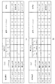
図7は、一実施形態に係る電源設定に係る要請メッセージに含まれた通信コードに対応し、車両内の機器の電源を設定した結果を示す表である。
In the following, the communication code, which is the criterion for determining the power supply condition, will be described in more detail.
FIG. 7 is a table showing a result of setting the power supplies of the devices in the vehicle corresponding to the communication code included in the request message for setting the power supply according to the embodiment.
車両内のユニットは、車両内のネットワーク綱を介して識別コード及び通信コードが含まれた電源設定に係る要請メッセージを電源制御装置に伝送することができる。このとき、電源制御装置は、電源設定に係る要請メッセージに含まれた識別コードを用いてどのユニットがメッセージを伝送したかを識別することができる。識別コードは、P(P≧1)ビットで表現することができる。例えば、識別コードは4ビットで表現することができる。図7に示すように、ユニットAの識別コードは「1000」、ユニットBの識別コードは「1001」、ユニットCの識別コードは「1010」に設定することができる。 The unit in the vehicle may transmit a request message related to the power setting including the identification code and the communication code to the power control device via the network in the vehicle. At this time, the power control device can identify which unit transmitted the message using the identification code included in the request message related to the power setting. The identification code can be represented by P (P≧1) bits. For example, the identification code can be represented by 4 bits. As shown in FIG. 7, the identification code of the unit A can be set to "1000", the identification code of the unit B can be set to "1001", and the identification code of the unit C can be set to "1010".
一方、電源制御装置は、電源設定に係る要請メッセージに含まれた通信コードを用いて電源条件を判断することができる。通信コードは、M(M≧1)ビットで表現することができる。例えば、図7に示すように、通信コードは4ビットで表現することができる。具体的な例として、「1000」は「12.0V」、「0100」は「7.5V」、「0010」は「5V」、「0101」は「3.3V」に対応することができる。 On the other hand, the power control device can determine the power condition by using the communication code included in the request message related to the power setting. The communication code can be represented by M (M≧1) bits. For example, as shown in FIG. 7, the communication code can be represented by 4 bits. As a specific example, "1000" can correspond to "12.0V", "0100" to "7.5V", "0010" to "5V", and "0101" to "3.3V".
一実施形態によれば、図7(a)に示すように、識別コード「1010」、通信コード「1000」が含まれた要請メッセージを受信した場合、電源制御装置は、ユニットCに「12V」の電源を供給することができる。また、識別コード「1000」、通信コード「0010」が含まれた要請メッセージを受信した場合、電源制御装置は、ユニットAに「5V」の電源を供給することができる。また、識別コード「1001」、通信コード「0101」が含まれた要請メッセージを受信した場合、電源制御装置は、ユニットBに「3.3V」の電源を供給することができる。 According to an exemplary embodiment, as illustrated in FIG. 7A, when the request message including the identification code “1010” and the communication code “1000” is received, the power control device may cause the unit C to “12V”. Can be powered. Also, when the request message including the identification code “1000” and the communication code “0010” is received, the power supply control device can supply the power of “5V” to the unit A. Also, when the request message including the identification code “1001” and the communication code “0101” is received, the power supply control device can supply the power of “3.3 V” to the unit B.
通信コードによる電源条件は予め設定され、車両内のメモリに保存されることができる。電源制御装置は、要請メッセージに含まれた通信コードとメモリに保存されたデータとを比較し、通信コードに対応する電源条件を判断することができる。通信コードが同一であっても、通信コードに対応する電源条件は相違し得る。例えば、通信コードが「1000」であっても使用者又は運営者の設定により通信コードに対応する電位は「12V」であることも、又は「5V」であることもできる。一方、通信コードのビット個数は車両に内蔵された機器の個数と対応されるように設定することができるが、これに限定されない。 The power supply condition based on the communication code can be set in advance and stored in the memory in the vehicle. The power controller may compare the communication code included in the request message with the data stored in the memory to determine the power condition corresponding to the communication code. Even if the communication code is the same, the power supply conditions corresponding to the communication code may be different. For example, even if the communication code is "1000", the potential corresponding to the communication code may be "12V" or "5V" depending on the setting of the user or the operator. On the other hand, the number of bits of the communication code can be set so as to correspond to the number of devices built in the vehicle, but is not limited to this.
図8は、一実施形態に係る車両内の機器に電源安定化回路が内蔵された場合と電源制御装置を用いて車両内の機器に注文型電源供給を提供する場合とを比較して示す図である。 FIG. 8 is a diagram showing a comparison between a case where a power supply stabilization circuit is built in a device in a vehicle according to an embodiment and a case where a power supply control device is used to provide a custom-made power supply to a device in the vehicle. Is.
図8(a)に示すように、ユニットA 164のような車両内の機器は、それぞれ電源安定化回路を設けて、印加した電源を機器に適切にレギュレーティングした後、メインボードに供給しなければならなかった。これにより、車両内の機器を実現するための材料費及び設計コストが増加するとともに、設計時間が増加するという短所がある。
As shown in FIG. 8A, in-vehicle devices such as the
図8(b)に示すように、電源制御装置100は、電源安定化回路を統合し、バッテリ又は車両発電機の電源のうちの少なくとも1つから受けた電源を安定化した後、車両内の機器のそれぞれに適切な電源を供給することができる。これにより、電源制御装置100は、車両内の機器のそれぞれに適切な注文型電源供給サービスを提供することができる。
As shown in FIG. 8B, the power
また、図8(a)に示すように、ユニットA 164は、電源を印加した6つの線と接続することができる。しかし、図8(b)に示すように、ユニットA 164は電源制御装置100と2つの線に接続して電源を受けることができる。これにより、電源制御装置100を介して4つの線か減少することで、ユニットA 164のハウジングの大きさ及びピン数を減少することができる。よって、ユニットA 164のコネクタ材料費も減少できる。
Further, as shown in FIG. 8A, the
例えば、車両内の機器がN個の場合、車両内の機器のそれぞれに含まれた電源安定化回路を除去し、電源安定化装置を介して統合することで、数式1のような材料費の節減効果を奏することができる。
For example, when the number of devices in the vehicle is N, by removing the power stabilizing circuit included in each of the devices in the vehicle and integrating them through the power stabilizing device, the material cost as shown in
[数1]
電源安定化回路の材料費節減額=電源安定化回路の材料費×N−電源安定化装置の材料費
[Equation 1]
Material cost reduction of power stabilization circuit = Material cost of power stabilization circuit x N-Material cost of power stabilization device
即ち、車両内の機器が増加するにつれ、材料費の節減額が増加され得る。また、電源制御装置は、車両内の機器の電源安定化回路を標準化、共用化することで、如何なる機器が車両内に追加されても、追加された機器に適切な電源を供給することができる。 That is, as the number of devices in the vehicle increases, the material cost saving may increase. Further, the power supply control device can supply appropriate power to the added device by standardizing and sharing the power supply stabilization circuit of the device in the vehicle, no matter what device is added in the vehicle. ..
図9は、車両に内蔵された多様な機器に適合する電源を供給する車両の制御方法を示す図である。
車両は、車両内の通信網を介して電源設定に係る要請メッセージを受信することができる(1000)。例えば、車両は、計測制御機通信網を介して電源供給を所望する機器から電源設定に係る要請メッセージを受信することができる。
FIG. 9 is a diagram showing a method of controlling a vehicle that supplies power suitable for various devices built into the vehicle.
The vehicle may receive a request message regarding power setting via a communication network in the vehicle (1000). For example, the vehicle may receive a request message regarding power setting from a device that desires power supply via the measurement controller communication network.
車両は、電源設定に係る要請メッセージに含まれた通信コードを用いて電源条件を判断することができる(1010)。車両内の機器の電源条件は異なっていても、同一であってもよい。よって、車両は、通信コードを用いて判断した電源条件に基づいて電源供給を所望する機器ごとに、機器に適切な電源を供給することができる。 The vehicle may determine the power condition using the communication code included in the power setting request message (1010). The power supply conditions of the devices in the vehicle may be different or the same. Therefore, the vehicle can supply appropriate power to each device for which power supply is desired based on the power condition determined by using the communication code.
車両は、バッテリ又は車両発電機の電源のうちの少なくとも1つから受けた電源を機器に適合するように変換し、変換された電源を機器に印加することを制御できる(1020)。一実施形態によれば、車両は、電源安定化回路を介してバッテリ又は車両発電機の電源のうちの少なくとも1つから受けた電源を安定化させるとともに、機器が要求する使用電圧に変換するレギュレーティング過程を行うことができる。 The vehicle may control converting power received from at least one of a battery or a power source of a vehicle generator to be compatible with the device and applying the converted power to the device (1020). According to one embodiment, the vehicle regulates the power received from at least one of the battery or the power source of the vehicle generator via the power stabilization circuit and converts the power into a working voltage required by the device. A rating process can be performed.
車両は、スイッチ回路を介してレギュレーティング過程を実行した電源を車両内の機器に印加することができる。これにより、車両は車両内の機器のそれぞれが直接バッテリ又は車両発電機の電源のうちの少なくとも1つから受けた電源に対してレギュレーティング過程を実行してメインボードに電源を供給しなければならないという短所を解消することができる。 The vehicle may apply the power, which has performed the regulation process, to the devices in the vehicle via the switch circuit. Accordingly, the vehicle has to perform a regulating process on the power supplied to each of the devices in the vehicle directly from at least one of the battery and the power source of the vehicle generator to supply power to the main board. That disadvantage can be eliminated.
一方、バッテリと車両発電機の電源は並列に接続され、バッテリが放電、又は車両発電機の電源が遮断しても、車両に電源を供給することができる。また、バッテリが放電した場合、バッテリと車両発電機の電源は並列に接続されているので、車両発電機の電源は車両内に電源を供給するとともに、バッテリに充電を行うことができる。 On the other hand, the battery and the power source of the vehicle generator are connected in parallel, and the power can be supplied to the vehicle even if the battery is discharged or the power source of the vehicle generator is shut off. Further, when the battery is discharged, the battery and the power supply of the vehicle generator are connected in parallel, so that the power supply of the vehicle generator can supply the power to the inside of the vehicle and charge the battery.
実施形態による方法は、多様なコンピュータ手段を介して実行できるプログラム命令形態として実現され、コンピュータ読み出し可能媒体に記録される。前記コンピュータ読み出し可能媒体は、プログラム命令、データファイル、データ構造などを単独又は組み合わせて含むことができる。前記媒体に記録されるプログラム命令は、実施形態のために特別に設計されて構成されたものであるか、又はコンピュータソフトウエア当業者に公知されて使用可能なものであってもよい。コンピュータ読み出し可能記録媒体の例としては、ハードディスク、フロッピー(登録商標)ディスク又は磁気テープのような磁気媒体(magnetic media)、CD−ROM、又はDVDのような光記録媒体(optical media)、フロプティカルディスク(floptical disk)のような光磁気媒体(magneto−optical media)、ロム(ROM)、又はラム(RAM)、フラッシュメモリなどのようなプログラム命令を保存して実行するように特別に構成されたハードウェア装置が含まれる。 The method according to the embodiment is implemented as a program instruction form that can be executed via various computer means, and is recorded on a computer-readable medium. The computer-readable medium may include program instructions, data files, data structures, etc. alone or in combination. The program instructions recorded on the medium may be those specially designed and constructed for the embodiment, or those known and usable by those skilled in the computer software art. Examples of the computer readable recording medium include a hard disk, a magnetic medium such as a floppy (registered trademark) disk or a magnetic tape, an optical recording medium such as a CD-ROM or a DVD, and a floppy disk. Specially configured to store and execute program instructions such as a magneto-optical medium such as a floppy disk, a ROM (ROM), or a RAM (RAM), a flash memory, or the like. Hardware devices are included.
プログラム命令の例としては、コンパイラにより生成される機械ワードコードだけでなく、インタープリタなどを用いてコンピュータで実行できる高級言語コードを含む。上記したハードウェア装置は、実施形態の動作を実行するために1つ以上のソフトウエアモジュールとして作動するように構成することができ、その逆の場合も同様である。 Examples of program instructions include not only machine word codes generated by a compiler, but also high-level language codes that can be executed by a computer using an interpreter or the like. The hardware devices described above may be configured to operate as one or more software modules to carry out the operations of the embodiments, and vice versa.
以上のように、実施形態を、たとえ限定された実施形態と図面とにより説明したが、該当技術分野で通常の知識を有する者であれば、上記の記載から多様な修正及び変形が可能である。例えば、説明の技術が説明された方法と異なる順序で実行されたり、及び/又は説明されたシステム、構造、装置、回路などの構成要素が説明した方法と異なる形態で結合又は組合されたり、他の構成要素又は均等物により対置されたり、置換されたりしても適切な結果に達することができる。 As described above, the embodiments have been described with the limited embodiments and the drawings. However, various modifications and variations can be made from the above description by a person having ordinary knowledge in the relevant technical field. .. For example, the described techniques may be performed in a different order than the described methods, and/or components such as described systems, structures, devices, circuits may be combined or combined in a different manner than the described methods, etc. Appropriate results can be achieved even if they are abutted or replaced by the components or equivalents of.
そのため、他の実現、他の実施形態及び特許請求の範囲と均等なものも、後述する特許請求の範囲に属する。 Therefore, other implementations, other embodiments, and equivalents to the claims also belong to the claims to be described later.
100 電源制御装置
101 ディスプレイ
102 ナビゲーション入力部
103 キーシリンダ
104 AVN端末
110 通信部
120 判断部
130 印加制御部
140 制御部
161 TMU
163 外装アンプ
167 ヘッドユニット
180 音声入力部
200 車両
100
163
Claims (15)
前記電源設定に係る要請メッセージに基づいて電源条件を判断する判断部と、
前記判断の結果に基づいてバッテリ及び車両発電機(alternator)の電源のうちの少なくとも1つから受けた電源を前記複数の機器に印加することを制御する印加制御部と、を含み、
前記電源設定に係る要請メッセージは、前記複数の機器それぞれが動作するために要求される電源条件を表す通信コードを含むことを特徴とする電源制御装置。 When the position of the ignition key is changed or a communication module included in a plurality of devices wakes up an in-vehicle measurement controller communication network (Controller Area Network, CAN) in response to a user's operation request, through the vehicle in the measurement controller communication network, a communication unit that receives a request message according from each of the plurality of devices having identical or different powering conditions to the power setting,
A determination unit that determines a power condition based on a request message related to the power setting,
See containing and a application controller for controlling the application of a power source which received from at least one of the power supply of the battery and the vehicle power generator (alternator), based on a result of the determination to said plurality of devices,
The power control device , wherein the request message related to the power setting includes a communication code indicating a power condition required for each of the plurality of devices to operate .
前記電源設定に係る要請メッセージに含まれた通信コードを用いて電源条件を判断することを特徴とする請求項1に記載の電源制御装置。 The judgment unit is
The power supply control device according to claim 1, wherein the power supply condition is determined by using a communication code included in the request message related to the power supply setting.
前記電源設定に係る要請メッセージに含まれた通信コードを用いて電源条件がイグニッション1(Ignition 1、IGN 1)、イグニッション2(Ignition 2、IGN 2)、アクセサリ(Accessory、ACC)、ST(Start)、B+、又はオフ(OFF)のうちの少なくとも1つの電源条件に該当するか否かを判断することを特徴とする請求項1に記載の電源制御装置。 The judgment unit is
The power supply conditions are ignition 1 (Ignition 1, IGN 1), ignition 2 (Ignition 2, IGN 2), accessories (Accessory, ACC), ST (Start) using the communication code included in the request message related to the power setting. The power supply control device according to claim 1, wherein it is determined whether or not at least one power supply condition of B, B+, or OFF is satisfied.
前記判断の結果に基づいて、バッテリ又は車両発電機の電源から受けた電源をイグニッション1、イグニッション2、アクセサリ、ST、B+、又はオフのうちの少なくとも1つの電源条件に対応する電源にレギュレーティング(regulating)し、印加を制御することを特徴とする請求項1に記載の電源制御装置。 The application control unit,
Based on the result of the determination , the power received from the battery or the power source of the vehicle generator is regulated to the power source corresponding to at least one power source condition of ignition 1, ignition 2, accessory, ST, B+, or off ( The power supply control device according to claim 1, wherein the power supply control device controls the application of the voltage.
前記判断の結果に基づいて電源印加の制御に対応して、電源条件が変更されたと判断すると、変更された電源条件に対応する電源への印加を制御することを特徴とする請求項1に記載の電源制御装置。 The application control unit,
The control of application of power based on the result of the determination, when it is determined that the power supply condition is changed, the application to the power supply corresponding to the changed power supply condition is controlled. Power controller.
前記電源設定に係る要請メッセージに基づいて電源条件を判断する判断部と、
前記判断の結果に基づいてバッテリ及び車両発電機(alternator)の電源のうちの少なくとも1つから受けた電源を前記複数の機器に印加することを制御する印加制御部と、を含み、
前記電源設定に係る要請メッセージは、前記複数の機器それぞれが動作するために要求される電源条件を表す通信コードを含むことを特徴とする車両。 When the position of the ignition key is changed or a communication module included in a plurality of devices wakes up an in-vehicle measurement controller communication network (Controller Area Network, CAN) in response to a user's operation request, through the vehicle in the measurement controller communication network, a communication unit that receives a request message according from each of the plurality of devices having identical or different powering conditions to the power setting,
A determination unit that determines a power condition based on a request message related to the power setting,
See containing and a application controller for controlling the application of a power source which received from at least one of the power supply of the battery and the vehicle power generator (alternator), based on a result of the determination to said plurality of devices,
The vehicle according to claim 1, wherein the request message related to the power setting includes a communication code indicating a power condition required for each of the plurality of devices to operate .
前記電源設定に係る要請メッセージに含まれた通信コードを用いて電源条件を判断することを特徴とする請求項6に記載の車両。 The judgment unit is
The vehicle according to claim 6 , wherein the power condition is determined using a communication code included in the request message related to the power setting.
前記電源設定に係る要請メッセージに含まれた通信コードを用いて電源条件が、イグニッション1、イグニッション2、アクセサリ、ST、B+又はオフのうちの少なくともいずれか1つの電源条件に該当するか否かを判断することを特徴とする請求項6に記載の車両。 The judgment unit is
It is determined whether the power supply condition corresponds to at least one of the power supply conditions of ignition 1, ignition 2, accessory, ST, B+, or off by using the communication code included in the request message related to the power setting. The vehicle according to claim 6 , wherein a determination is made.
前記判断の結果に基づいて、バッテリ又は車両発電機の電源から受けた電源をイグニッション1、イグニッション2、アクセサリ、ST、B+、又はオフのうちの少なくともいずれか1つの電源条件に対応する電源にレギュレーティングし、印加を制御することを特徴とする請求項6に記載の車両。 The application control unit,
Based on the result of the determination, the power received from the battery or the power source of the vehicle generator is regulated to the power source corresponding to at least one of the power source conditions of ignition 1, ignition 2, accessory, ST, B+, or off. 7. The vehicle according to claim 6 , wherein the vehicle is rated and the application is controlled.
前記判断の結果に基づいて電源印加の制御に対応し、電源条件が変更されたと判断すると、変更された電源条件に対応する電源への印加を制御することを特徴とする請求項6に記載の車両。 The application control unit,
Corresponding to the control of the power applied on the basis of a result of the determination, when it is determined that the power condition is changed, according to claim 6, characterized in that to control the application of the power corresponding to the changed power requirements vehicle.
前記電源設定に係る要請メッセージに基づいて電源条件を判断する段階と、
前記判断の結果に基づいてバッテリ及び車両発電機(alternator)の電源のうちの少なくとも1つから受けた電源を前記複数の機器に印加することを制御する段階と、を含み、
前記電源設定に係る要請メッセージは、前記複数の機器それぞれが動作するために要求される電源条件を表す通信コードを含むことを特徴とする車両の制御方法。 When the position of the ignition key is changed or a communication module included in a plurality of devices wakes up an in-vehicle measurement controller communication network (Controller Area Network, CAN) in response to a user's operation request, through the vehicle in the measurement control device communications network, receiving a request message relating from each of the plurality of devices having identical or different powering conditions to the power setting,
Determining a power condition based on a request message related to the power setting,
Look including the the steps of controlling the application of a power source which received from at least one of the power supply of the battery and the vehicle power generator (alternator) to the plurality of devices based on a result of the determination,
The vehicle control method , wherein the request message related to the power setting includes a communication code indicating a power condition required for each of the plurality of devices to operate .
前記電源設定に係る要請メッセージに含まれた通信コードを用いて電源条件を判断することを特徴とする請求項11に記載の車両の制御方法。 The determining step includes
The vehicle control method according to claim 11 , wherein the power condition is determined using a communication code included in the request message related to the power setting.
前記電源設定に係る要請メッセージに含まれた通信コードを用いて電源条件がイグニッション1、イグニッション2、アクセサリ、ST、B+、又はオフのうちの少なくともいずれか1つの電源条件に該当するか否かを判断することを特徴とする請求項11に記載の車両の制御方法。 The determining step includes
It is determined whether the power condition corresponds to at least one power condition of ignition 1, ignition 2, accessory, ST, B+, or off by using the communication code included in the request message related to the power setting. The method of controlling a vehicle according to claim 11 , wherein the determination is performed.
前記判断の結果に基づいて、バッテリ又は車両発電機の電源から受けた電源をイグニッション1、イグニッション2、アクセサリ、ST、B+、又はオフのうちの少なくとも1つの電源条件に対応する電源にレギュレーティングし、印加を制御することを特徴とする請求項11に記載の車両の制御方法。 The controlling step includes
Based on the result of the determination , the power received from the battery or the power supply of the vehicle generator is regulated to a power supply corresponding to at least one of the power supply conditions of ignition 1, ignition 2, accessory, ST, B+, or off. The control method of the vehicle according to claim 11 , wherein the application is controlled.
前記判断の結果に基づいて電源印加の制御に対応し、電源条件が変更されたと判断すると、変更された電源条件に対応する電源への印加を制御することを特徴とする請求項11に記載の車両の制御方法。
The supply stage is
Corresponding to the control of the power applied on the basis of a result of the determination, when it is determined that the power condition is changed, according to claim 11, characterized by controlling the application of the power corresponding to the changed power requirements Vehicle control method.
Applications Claiming Priority (2)
| Application Number | Priority Date | Filing Date | Title |
|---|---|---|---|
| KR10-2015-0142924 | 2015-10-13 | ||
| KR1020150142924A KR101763582B1 (en) | 2015-10-13 | 2015-10-13 | Power control apparatus, vehicle having the same, and method for contolling vehicle |
Publications (2)
| Publication Number | Publication Date |
|---|---|
| JP2017074938A JP2017074938A (en) | 2017-04-20 |
| JP6730809B2 true JP6730809B2 (en) | 2020-07-29 |
Family
ID=58405864
Family Applications (1)
| Application Number | Title | Priority Date | Filing Date |
|---|---|---|---|
| JP2016010515A Active JP6730809B2 (en) | 2015-10-13 | 2016-01-22 | Power control device, vehicle including the same, and vehicle control method |
Country Status (5)
| Country | Link |
|---|---|
| US (1) | US10000169B2 (en) |
| JP (1) | JP6730809B2 (en) |
| KR (1) | KR101763582B1 (en) |
| CN (1) | CN106564452B (en) |
| DE (1) | DE102015225132A1 (en) |
Families Citing this family (3)
| Publication number | Priority date | Publication date | Assignee | Title |
|---|---|---|---|---|
| KR102468444B1 (en) * | 2017-10-31 | 2022-11-17 | 미츠비시 쥬고 기카이 시스템 가부시키가이샤 | Power supply control device, vehicle equipped with the power supply control device, power supply control method, and power supply control program |
| JP2020137296A (en) * | 2019-02-21 | 2020-08-31 | 株式会社デンソー | On-vehicle equipment power supply device |
| CN116653600A (en) * | 2023-05-16 | 2023-08-29 | 名商科技有限公司 | Vehicle-mounted power supply management method and system for precisely controlling power |
Family Cites Families (14)
| Publication number | Priority date | Publication date | Assignee | Title |
|---|---|---|---|---|
| GB8701496D0 (en) * | 1987-01-23 | 1987-02-25 | Salplex Ltd | Information handling & control systems |
| JPH0721462A (en) * | 1993-07-05 | 1995-01-24 | Seiko Epson Corp | Electron register |
| JP2002111470A (en) * | 2000-10-03 | 2002-04-12 | Hitachi Ltd | Semiconductor device |
| JP4047049B2 (en) * | 2002-04-02 | 2008-02-13 | 矢崎総業株式会社 | Load condition monitoring system |
| JP4494736B2 (en) * | 2003-08-08 | 2010-06-30 | 株式会社東海理化電機製作所 | Engine start control device |
| EP1958375B1 (en) * | 2005-11-15 | 2014-06-25 | Linear Technology Corporation | Dynamic power allocation in system for providing power over communication link |
| US7420292B2 (en) * | 2006-04-13 | 2008-09-02 | Eaton Corporation | Vehicle bus control system |
| JP2011093389A (en) * | 2009-10-28 | 2011-05-12 | Autonetworks Technologies Ltd | Control system, electronic devices, control device, and method for starting devices |
| JP4947127B2 (en) * | 2009-11-19 | 2012-06-06 | アンデン株式会社 | Vehicle power circuit |
| JP2012192754A (en) * | 2011-03-15 | 2012-10-11 | Omron Automotive Electronics Co Ltd | In-vehicle apparatus control device |
| DE102011086829A1 (en) * | 2011-11-22 | 2013-05-23 | Continental Automotive Gmbh | On-board network and method for operating a vehicle electrical system |
| JP5741496B2 (en) * | 2012-03-14 | 2015-07-01 | 株式会社オートネットワーク技術研究所 | In-vehicle communication system |
| CN104217578A (en) * | 2013-05-31 | 2014-12-17 | 现代自动车株式会社 | Vehicle managing system and method |
| CA2933162C (en) * | 2013-10-11 | 2019-09-10 | The Boeing Company | Modular equipment center solid state primary power switching network |
-
2015
- 2015-10-13 KR KR1020150142924A patent/KR101763582B1/en active IP Right Grant
- 2015-12-03 US US14/958,464 patent/US10000169B2/en active Active
- 2015-12-14 DE DE102015225132.2A patent/DE102015225132A1/en active Pending
-
2016
- 2016-01-22 JP JP2016010515A patent/JP6730809B2/en active Active
- 2016-02-19 CN CN201610095068.1A patent/CN106564452B/en active Active
Also Published As
| Publication number | Publication date |
|---|---|
| CN106564452A (en) | 2017-04-19 |
| CN106564452B (en) | 2021-10-08 |
| KR20170043320A (en) | 2017-04-21 |
| US20170101068A1 (en) | 2017-04-13 |
| US10000169B2 (en) | 2018-06-19 |
| DE102015225132A1 (en) | 2017-04-13 |
| JP2017074938A (en) | 2017-04-20 |
| KR101763582B1 (en) | 2017-08-01 |
Similar Documents
| Publication | Publication Date | Title |
|---|---|---|
| JP4279854B2 (en) | Vehicle power supply control device | |
| EP3250417B1 (en) | Controlling vehicle systems with mobile devices | |
| JP6730809B2 (en) | Power control device, vehicle including the same, and vehicle control method | |
| CN103812162A (en) | System and method for reducing thermal conditions during wireless charging | |
| US9533549B2 (en) | System and method for controlling heating modes for hybrid electric vehicle (HEV) | |
| JP7421308B2 (en) | Vehicle power management device and method | |
| JP2018535645A (en) | Power charging module and method of using the same | |
| KR101796989B1 (en) | Amplifier for vehicle and vehicle thereof | |
| KR20190068785A (en) | Vehicle and method for controlling thereof | |
| CN108973901B (en) | Vehicle accessory power management | |
| JP2009083567A (en) | Air-conditioning control device of electric automobile | |
| CN102848921A (en) | Device for displaying | |
| JP3373664B2 (en) | Power supply for vehicle | |
| KR102485380B1 (en) | Apparatus for controlling alternator of vehicle and method thereof | |
| KR20190083395A (en) | Vehicle and method for controlling thereof | |
| JP6003925B2 (en) | Electronic control device for vehicle | |
| CN103457813B (en) | Aftermarket module arrangement and method for communicating over a vehicle bus | |
| KR20200064382A (en) | Vehicle and method for controlling thereof | |
| KR101588187B1 (en) | Navigation device, vehicle having the same, and method for contolling vehicle | |
| KR101656809B1 (en) | User interface device, Vehicle having the same and method for controlling the same | |
| KR101611203B1 (en) | Light control apparatus, Vehicle having the same and method for controlling the same | |
| WO2021100310A1 (en) | Vehicular control device, vehicular system, and vehicular control method | |
| JPH06276571A (en) | Multiple transmission device | |
| KR200463420Y1 (en) | Charger module for vehicle | |
| JP2016112953A (en) | Instrument for vehicle |
Legal Events
| Date | Code | Title | Description |
|---|---|---|---|
| A621 | Written request for application examination |
Free format text: JAPANESE INTERMEDIATE CODE: A621 Effective date: 20190111 |
|
| A977 | Report on retrieval |
Free format text: JAPANESE INTERMEDIATE CODE: A971007 Effective date: 20191209 |
|
| A131 | Notification of reasons for refusal |
Free format text: JAPANESE INTERMEDIATE CODE: A131 Effective date: 20200107 |
|
| A521 | Request for written amendment filed |
Free format text: JAPANESE INTERMEDIATE CODE: A523 Effective date: 20200407 |
|
| TRDD | Decision of grant or rejection written | ||
| A01 | Written decision to grant a patent or to grant a registration (utility model) |
Free format text: JAPANESE INTERMEDIATE CODE: A01 Effective date: 20200623 |
|
| A61 | First payment of annual fees (during grant procedure) |
Free format text: JAPANESE INTERMEDIATE CODE: A61 Effective date: 20200703 |
|
| R150 | Certificate of patent or registration of utility model |
Ref document number: 6730809 Country of ref document: JP Free format text: JAPANESE INTERMEDIATE CODE: R150 |
|
| R250 | Receipt of annual fees |
Free format text: JAPANESE INTERMEDIATE CODE: R250 |