JP6729409B2 - Perimeter monitoring device - Google Patents
Perimeter monitoring device Download PDFInfo
- Publication number
- JP6729409B2 JP6729409B2 JP2017005097A JP2017005097A JP6729409B2 JP 6729409 B2 JP6729409 B2 JP 6729409B2 JP 2017005097 A JP2017005097 A JP 2017005097A JP 2017005097 A JP2017005097 A JP 2017005097A JP 6729409 B2 JP6729409 B2 JP 6729409B2
- Authority
- JP
- Japan
- Prior art keywords
- image
- vehicle
- timing
- processing unit
- mode
- Prior art date
- Legal status (The legal status is an assumption and is not a legal conclusion. Google has not performed a legal analysis and makes no representation as to the accuracy of the status listed.)
- Active
Links
- 238000012806 monitoring device Methods 0.000 title claims description 54
- 238000012545 processing Methods 0.000 claims description 83
- 238000003384 imaging method Methods 0.000 claims description 18
- 238000001514 detection method Methods 0.000 claims description 13
- 230000005540 biological transmission Effects 0.000 claims description 12
- 230000007246 mechanism Effects 0.000 claims description 10
- 230000008878 coupling Effects 0.000 claims description 8
- 238000010168 coupling process Methods 0.000 claims description 8
- 238000005859 coupling reaction Methods 0.000 claims description 8
- 238000000034 method Methods 0.000 description 40
- 238000010586 diagram Methods 0.000 description 18
- 230000002093 peripheral effect Effects 0.000 description 15
- 230000008569 process Effects 0.000 description 8
- 238000009434 installation Methods 0.000 description 7
- 230000007704 transition Effects 0.000 description 7
- 238000005259 measurement Methods 0.000 description 5
- 244000261422 Lysimachia clethroides Species 0.000 description 4
- 230000015654 memory Effects 0.000 description 4
- 238000002485 combustion reaction Methods 0.000 description 3
- 230000004397 blinking Effects 0.000 description 2
- 230000008859 change Effects 0.000 description 2
- 238000006243 chemical reaction Methods 0.000 description 2
- 230000007423 decrease Effects 0.000 description 2
- 230000006870 function Effects 0.000 description 2
- 230000003287 optical effect Effects 0.000 description 2
- 239000007787 solid Substances 0.000 description 2
- 230000001133 acceleration Effects 0.000 description 1
- 238000013459 approach Methods 0.000 description 1
- 238000000605 extraction Methods 0.000 description 1
- 239000000446 fuel Substances 0.000 description 1
- 239000004973 liquid crystal related substance Substances 0.000 description 1
- 238000012986 modification Methods 0.000 description 1
- 230000004048 modification Effects 0.000 description 1
- 230000007935 neutral effect Effects 0.000 description 1
- 238000012856 packing Methods 0.000 description 1
- 238000010187 selection method Methods 0.000 description 1
Images


Classifications
-
- B—PERFORMING OPERATIONS; TRANSPORTING
- B60—VEHICLES IN GENERAL
- B60D—VEHICLE CONNECTIONS
- B60D1/00—Traction couplings; Hitches; Draw-gear; Towing devices
- B60D1/58—Auxiliary devices
- B60D1/62—Auxiliary devices involving supply lines, electric circuits, or the like
-
- B—PERFORMING OPERATIONS; TRANSPORTING
- B60—VEHICLES IN GENERAL
- B60R—VEHICLES, VEHICLE FITTINGS, OR VEHICLE PARTS, NOT OTHERWISE PROVIDED FOR
- B60R1/00—Optical viewing arrangements; Real-time viewing arrangements for drivers or passengers using optical image capturing systems, e.g. cameras or video systems specially adapted for use in or on vehicles
- B60R1/002—Optical viewing arrangements; Real-time viewing arrangements for drivers or passengers using optical image capturing systems, e.g. cameras or video systems specially adapted for use in or on vehicles specially adapted for covering the peripheral part of the vehicle, e.g. for viewing tyres, bumpers or the like
- B60R1/003—Optical viewing arrangements; Real-time viewing arrangements for drivers or passengers using optical image capturing systems, e.g. cameras or video systems specially adapted for use in or on vehicles specially adapted for covering the peripheral part of the vehicle, e.g. for viewing tyres, bumpers or the like for viewing trailer hitches
-
- B—PERFORMING OPERATIONS; TRANSPORTING
- B60—VEHICLES IN GENERAL
- B60D—VEHICLE CONNECTIONS
- B60D1/00—Traction couplings; Hitches; Draw-gear; Towing devices
- B60D1/24—Traction couplings; Hitches; Draw-gear; Towing devices characterised by arrangements for particular functions
- B60D1/36—Traction couplings; Hitches; Draw-gear; Towing devices characterised by arrangements for particular functions for facilitating connection, e.g. hitch catchers, visual guide means, signalling aids
- B60D1/363—Hitch guiding or catching elements, e.g. V-shaped plates partially surrounding a coupling member for guiding the other coupling member
-
- B—PERFORMING OPERATIONS; TRANSPORTING
- B60—VEHICLES IN GENERAL
- B60D—VEHICLE CONNECTIONS
- B60D1/00—Traction couplings; Hitches; Draw-gear; Towing devices
- B60D1/48—Traction couplings; Hitches; Draw-gear; Towing devices characterised by the mounting
- B60D1/488—Traction couplings; Hitches; Draw-gear; Towing devices characterised by the mounting mounted directly to the chassis of the towing vehicle
-
- B—PERFORMING OPERATIONS; TRANSPORTING
- B60—VEHICLES IN GENERAL
- B60R—VEHICLES, VEHICLE FITTINGS, OR VEHICLE PARTS, NOT OTHERWISE PROVIDED FOR
- B60R1/00—Optical viewing arrangements; Real-time viewing arrangements for drivers or passengers using optical image capturing systems, e.g. cameras or video systems specially adapted for use in or on vehicles
- B60R1/20—Real-time viewing arrangements for drivers or passengers using optical image capturing systems, e.g. cameras or video systems specially adapted for use in or on vehicles
- B60R1/22—Real-time viewing arrangements for drivers or passengers using optical image capturing systems, e.g. cameras or video systems specially adapted for use in or on vehicles for viewing an area outside the vehicle, e.g. the exterior of the vehicle
- B60R1/23—Real-time viewing arrangements for drivers or passengers using optical image capturing systems, e.g. cameras or video systems specially adapted for use in or on vehicles for viewing an area outside the vehicle, e.g. the exterior of the vehicle with a predetermined field of view
- B60R1/26—Real-time viewing arrangements for drivers or passengers using optical image capturing systems, e.g. cameras or video systems specially adapted for use in or on vehicles for viewing an area outside the vehicle, e.g. the exterior of the vehicle with a predetermined field of view to the rear of the vehicle
-
- B—PERFORMING OPERATIONS; TRANSPORTING
- B60—VEHICLES IN GENERAL
- B60R—VEHICLES, VEHICLE FITTINGS, OR VEHICLE PARTS, NOT OTHERWISE PROVIDED FOR
- B60R11/00—Arrangements for holding or mounting articles, not otherwise provided for
- B60R11/04—Mounting of cameras operative during drive; Arrangement of controls thereof relative to the vehicle
-
- B—PERFORMING OPERATIONS; TRANSPORTING
- B60—VEHICLES IN GENERAL
- B60R—VEHICLES, VEHICLE FITTINGS, OR VEHICLE PARTS, NOT OTHERWISE PROVIDED FOR
- B60R16/00—Electric or fluid circuits specially adapted for vehicles and not otherwise provided for; Arrangement of elements of electric or fluid circuits specially adapted for vehicles and not otherwise provided for
- B60R16/02—Electric or fluid circuits specially adapted for vehicles and not otherwise provided for; Arrangement of elements of electric or fluid circuits specially adapted for vehicles and not otherwise provided for electric constitutive elements
- B60R16/023—Electric or fluid circuits specially adapted for vehicles and not otherwise provided for; Arrangement of elements of electric or fluid circuits specially adapted for vehicles and not otherwise provided for electric constitutive elements for transmission of signals between vehicle parts or subsystems
-
- H—ELECTRICITY
- H04—ELECTRIC COMMUNICATION TECHNIQUE
- H04N—PICTORIAL COMMUNICATION, e.g. TELEVISION
- H04N7/00—Television systems
- H04N7/18—Closed-circuit television [CCTV] systems, i.e. systems in which the video signal is not broadcast
-
- B—PERFORMING OPERATIONS; TRANSPORTING
- B60—VEHICLES IN GENERAL
- B60R—VEHICLES, VEHICLE FITTINGS, OR VEHICLE PARTS, NOT OTHERWISE PROVIDED FOR
- B60R2300/00—Details of viewing arrangements using cameras and displays, specially adapted for use in a vehicle
- B60R2300/60—Details of viewing arrangements using cameras and displays, specially adapted for use in a vehicle characterised by monitoring and displaying vehicle exterior scenes from a transformed perspective
- B60R2300/607—Details of viewing arrangements using cameras and displays, specially adapted for use in a vehicle characterised by monitoring and displaying vehicle exterior scenes from a transformed perspective from a bird's eye viewpoint
-
- B—PERFORMING OPERATIONS; TRANSPORTING
- B60—VEHICLES IN GENERAL
- B60R—VEHICLES, VEHICLE FITTINGS, OR VEHICLE PARTS, NOT OTHERWISE PROVIDED FOR
- B60R2300/00—Details of viewing arrangements using cameras and displays, specially adapted for use in a vehicle
- B60R2300/80—Details of viewing arrangements using cameras and displays, specially adapted for use in a vehicle characterised by the intended use of the viewing arrangement
- B60R2300/802—Details of viewing arrangements using cameras and displays, specially adapted for use in a vehicle characterised by the intended use of the viewing arrangement for monitoring and displaying vehicle exterior blind spot views
- B60R2300/8026—Details of viewing arrangements using cameras and displays, specially adapted for use in a vehicle characterised by the intended use of the viewing arrangement for monitoring and displaying vehicle exterior blind spot views in addition to a rear-view mirror system
-
- B—PERFORMING OPERATIONS; TRANSPORTING
- B60—VEHICLES IN GENERAL
- B60R—VEHICLES, VEHICLE FITTINGS, OR VEHICLE PARTS, NOT OTHERWISE PROVIDED FOR
- B60R2300/00—Details of viewing arrangements using cameras and displays, specially adapted for use in a vehicle
- B60R2300/80—Details of viewing arrangements using cameras and displays, specially adapted for use in a vehicle characterised by the intended use of the viewing arrangement
- B60R2300/808—Details of viewing arrangements using cameras and displays, specially adapted for use in a vehicle characterised by the intended use of the viewing arrangement for facilitating docking to a trailer
Landscapes
- Engineering & Computer Science (AREA)
- Mechanical Engineering (AREA)
- Multimedia (AREA)
- Transportation (AREA)
- Signal Processing (AREA)
- Closed-Circuit Television Systems (AREA)
Description
本発明の実施形態は、周辺監視装置に関する。 Embodiments of the present invention relate to a surroundings monitoring device.
従来、車両に設置された撮像装置で車両の後方の周辺環境を撮像し、撮像された画像を車室内に設けられた表示画面を介して運転者に提供する技術がある。 2. Description of the Related Art Conventionally, there is a technique in which an imaging device installed in a vehicle captures an image of a surrounding environment behind the vehicle and provides the captured image to a driver via a display screen provided in the vehicle interior.
また、従来、キャンピングカーなどの被牽引車を牽引することができる車両がある。 Further, conventionally, there are vehicles capable of towing a towed vehicle such as a camper.
車両に設けられた連結装置と被牽引車に設けられた連結装置とを車両を被牽引車に向かって後退させることによって連結する場合がある。そのような場合、運転者は、車両を運転しながら双方の連結装置の位置合わせを行う必要がある。 In some cases, the connecting device provided on the vehicle and the connecting device provided on the towed vehicle are connected by retracting the vehicle toward the towed vehicle. In such a case, the driver needs to align both coupling devices while driving the vehicle.
本発明の課題の一つは、車両に被牽引車を連結する際に連結装置間の位置合わせを行いやすくする周辺監視装置を提供することである。 An object of the present invention is to provide a surroundings monitoring device that facilitates alignment between connecting devices when connecting a towed vehicle to a vehicle.
本発明の実施形態の周辺監視装置は、一例として、被牽引車を連結するための第1の連結装置を有する車両の第1の後方画像を第1のタイミングに取得する取得部と、第1のタイミングよりも後の第2のタイミングにおいて、第1の連結装置の第2のタイミングの位置を示す第1の識別情報を第1の後方画像に重畳し、第1の識別情報が重畳された第1の後方画像を車両の室内に設けられた表示画面に表示する画像処理部と、を備えた。運転者は、表示画面を介して第1の連結装置のリアルタイムの位置を確認することが可能であるので、周辺監視装置は、連結装置間の位置合わせを行いやすくすることができる。 The periphery monitoring device according to the embodiment of the present invention includes, as an example, an acquisition unit that acquires a first rear image of a vehicle having a first connecting device for connecting a towed vehicle at a first timing, At the second timing after the timing of, the first identification information indicating the position of the second timing of the first coupling device is superimposed on the first rear image, and the first identification information is superimposed. An image processing unit for displaying the first rear image on a display screen provided in the vehicle compartment. Since the driver can confirm the real-time position of the first connecting device via the display screen, the peripheral monitoring device can facilitate the alignment between the connecting devices.
また、本発明の実施形態の周辺監視装置では、一例として、車両に撮像装置が設けられ、第1の連結装置は、撮像装置の死角領域に設けられ、取得部は、車両に設けられた撮像装置から第1の後方画像を取得する。周辺監視装置は、第1の連結装置が撮像装置の死角領域に設けられている場合であっても表示画面に第1の連結装置のリアルタイムの位置を示すことができるので、運転者は、表示画面を介して第1の連結装置のリアルタイムの位置を確認することが可能である。 Further, in the periphery monitoring device of the embodiment of the present invention, as an example, the vehicle is provided with an imaging device, the first coupling device is provided in a blind spot area of the imaging device, and the acquisition unit is provided in the vehicle. Acquire a first posterior image from the device. The peripheral monitoring device can show the real-time position of the first coupling device on the display screen even when the first coupling device is provided in the blind spot area of the imaging device. It is possible to confirm the real-time position of the first connecting device via the screen.
また、本発明の実施形態の周辺監視装置では、一例として、画像処理部は、被牽引車に設けられた第1の連結装置と連結する第2の連結装置の先端から地面まで延伸する第2の識別情報を第1の後方画像にさらに重畳する。よって、運転者は、表示画面を視認することによって、第2の連結装置の先端の高さを直感的に認識することが可能となる。 Further, in the perimeter monitoring device according to the embodiment of the present invention, as an example, the image processing unit may extend from the tip of the second connecting device provided on the towed vehicle to the ground to the second connecting device connected to the first connecting device. Identification information is further superimposed on the first rear image. Therefore, the driver can intuitively recognize the height of the tip of the second coupling device by visually recognizing the display screen.
また、本発明の実施形態の周辺監視装置では、一例として、取得部は、第3のタイミングに第2の後方画像を取得し、画像処理部は、取得された第2の後方画像を表示画面に第3のタイミングの後に即時的に表示し、第3のタイミングは、第1モードで動作中のタイミングであり、第2のタイミングは、第1モードと異なる第2モードで動作中のタイミングである。よって、周辺監視装置が第1のモードで動作しているとき、運転者は、撮像装置の撮像領域内の状態をリアルタイムの実写画像によって確認することが可能である。 Further, in the periphery monitoring device of the embodiment of the present invention, as an example, the acquisition unit acquires the second rear image at the third timing, and the image processing unit displays the acquired second rear image on the display screen. Is displayed immediately after the third timing, the third timing is a timing when operating in the first mode, and the second timing is a timing when operating in a second mode different from the first mode. is there. Therefore, when the periphery monitoring device is operating in the first mode, the driver can confirm the state in the image pickup area of the image pickup device by a real-time photographed image.
また、本発明の実施形態の周辺監視装置では、一例として、取得部は、モード切り替えの操作入力、または車両の変速機構のレンジをリバースレンジから他のレンジに切り替える操作入力、またはテールゲートを閉状態から開状態にする操作入力、または車両に設けられた車両と被牽引車との距離を検出する測距装置からの検出情報、を取得し、周辺監視装置は、取得されたいずれかの操作入力または検出情報に基づいて第1モードから第2モードに遷移する。よって、周辺監視装置は、種々の事象をトリガとしてモード間の遷移を行うことができる。 Further, in the surroundings monitoring device according to the embodiment of the present invention, as an example, the acquisition unit may include a mode switching operation input, an operation input for switching the range of the transmission mechanism of the vehicle from the reverse range to another range, or closing the tailgate. The operation input from the state to the open state or the detection information from the distance measuring device provided on the vehicle for detecting the distance between the vehicle and the towed vehicle is acquired, and the peripheral monitoring device is operated by any of the acquired operations. A transition is made from the first mode to the second mode based on input or detection information. Therefore, the peripheral monitoring device can perform transition between modes by using various events as a trigger.
以下、本実施形態の周辺監視装置を車両1に搭載した例をあげて説明する。 Hereinafter, an example in which the periphery monitoring device of the present embodiment is mounted on the vehicle 1 will be described.
<実施形態>
実施形態の車両1は、例えば、不図示の内燃機関を駆動源とする自動車、すなわち内燃機関自動車であってもよいし、不図示の電動機を駆動源とする自動車、すなわち電気自動車または燃料電池自動車等であってもよいし、それらの双方を駆動源とするハイブリッド自動車であってもよいし、他の駆動源を備えた自動車であってもよい。また、車両1は、種々の変速装置を搭載することができるし、内燃機関や電動機を駆動するのに必要な種々の装置、例えばシステムや部品等を搭載することができる。また、車両1における車輪3の駆動に関わる装置の方式、数、およびレイアウト等は、種々に設定することができる。
<Embodiment>
The vehicle 1 of the embodiment may be, for example, a vehicle that uses an internal combustion engine (not shown) as a drive source, that is, an internal combustion engine vehicle, or a vehicle that uses an electric motor (not shown) as a drive source, that is, an electric vehicle or a fuel cell vehicle. Etc., a hybrid vehicle using both of them as drive sources, or a vehicle provided with another drive source. Further, the vehicle 1 can be equipped with various transmission devices, and can be equipped with various devices necessary for driving the internal combustion engine and the electric motor, such as systems and parts. In addition, the method, number, layout, and the like of devices related to driving the
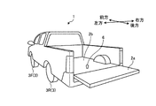
図1は、実施形態の周辺監視装置を搭載する車両1が示された側面図である。図1では、紙面左方向を車両1を基準とする前方、紙面右方向を車両1を基準とする後方としている。図2および図3は、実施形態の周辺監視装置を搭載する車両1を左後方から見た斜視図である。図2および図3では、紙面左上方向が車両1を基準とする前方であり、紙面左下方向が車両1を基準とする左方であり、紙面右下方向が車両1を基準とする後方であり、紙面右上方向が車両1を基準とする右方である。図4は、実施形態の周辺監視装置を搭載する車両1の車室内の一例を示す図であり、車両1の後方から車室内を見た図である。 FIG. 1 is a side view showing a vehicle 1 equipped with the periphery monitoring device of the embodiment. In FIG. 1, the left side of the drawing is the front with respect to the vehicle 1, and the right side of the drawing is the rear with respect to the vehicle 1. 2 and 3 are perspective views of the vehicle 1 equipped with the periphery monitoring device of the embodiment, as viewed from the left rear. 2 and 3, the upper left direction on the paper is the front with respect to the vehicle 1, the lower left direction on the paper is the left with respect to the vehicle 1, and the lower right direction on the paper is the rear with respect to the vehicle 1. The upper right direction on the paper is the right side with respect to the vehicle 1. FIG. 4 is a diagram showing an example of a vehicle interior of the vehicle 1 equipped with the periphery monitoring device of the embodiment, and is a view of the vehicle interior as seen from the rear of the vehicle 1.
実施形態の周辺監視装置を搭載する車両1は、左右二つの前輪3Fと、左右二つの後輪3Rとを有する。そして、車両1の後ろ側には、開放式の荷台2が設けられている。このようなタイプの車両1は、ピックアップトラックと呼ばれる。荷台2のバックパネル(テールゲート)2aは、荷台2の底部2bの後端に開閉自在に取り付けられている。図1および図2は、バックパネル2aが閉状態であるときの車両1を示しており、図3は、バックパネル2aが開状態であるときの車両1を示している。
The vehicle 1 equipped with the perimeter monitoring device of the embodiment has two left and right
バックパネル2aの中央には、カメラ4が設けられている。カメラ4は、CCD(charge coupled device)、またはCIS(CMOS image sensor)、等の撮像素子を内蔵する撮像装置である。カメラ4は、撮像素子によって撮像された画像を所定のフレームレートで後述のECU(Electronic Control Unit)12に出力する。
A camera 4 is provided at the center of the
車両1の周辺環境のうちの後方の領域を撮像可能なように、カメラ4の向き、カメラ4の画角、およびカメラ4の設置位置が決められている。これにより、カメラ4は、車両1の後方の領域が写っている画像である後方画像を撮像することができる。なお、カメラ4の設置位置はバックパネル2aの中央に限定されない。また、カメラ4の数は、1に限定されない。ECU12が、複数のカメラ4からの画像を合成することによって後方画像を生成してもよい。
The orientation of the camera 4, the angle of view of the camera 4, and the installation position of the camera 4 are determined so that an area behind the vehicle 1 can be imaged. As a result, the camera 4 can capture a rear image that is an image showing a region behind the vehicle 1. The installation position of the camera 4 is not limited to the center of the
車両1のリアバンパーには、ソナーセンサ5が設けられている。ソナーセンサ5は、車両1の後方の物体までの距離を測定する測距装置である。測距装置としては、ソナーセンサ5の代わりに、レーザレンジスキャナ、ステレオカメラ、など、他の種類の装置が採用可能である。ソナーセンサ5は検出した距離を検出情報として出力する。なお、ソナーセンサ5の設置位置は、上記に限定されない。また、ソナーセンサ5の設置数は、1に限定されない。
A
また、図4に例示されるように、車両1の室内には、表示画面8を有するモニタ装置10が設けられている。表示画面8は、例えば、LCD(liquid crystal display)またはOELD(organic electroluminescent display)等によって構成される。また、表示画面8は透明な操作入力部9で覆われている。操作入力部9は、例えばタッチパネルである。運転者は、操作入力部9を介して表示画面8に表示される画像を視認することができる。また、運転者は、表示画面8に表示される画像に対応した位置で手指等で操作入力部9を触れたり押したり動かしたりして操作することで、操作入力を実行することができる。モニタ装置10は、例えば、ダッシュボードの車幅方向すなわち左右方向の中央部に設けられている。モニタ装置10は、タッチパネル以外の操作入力部を備え得る。例えば、モニタ装置10は、他の操作入力部として、スイッチ、ダイヤル、ジョイスティック、または押しボタンが設けられていてもよい。モニタ装置10は、例えば、ナビゲーションシステムやオーディオシステムと兼用され得る。
Further, as illustrated in FIG. 4, a
また、車室内において、センターコンソールには、変速機構を操作するためのシフトレバー11が設けられている。例えば車両1に搭載される変速機構がオートマチックトランスミッションである場合、運転者は、シフトレバー11を操作することによって、パーキングレンジ、リバースレンジ、ニュートラルレンジ、およびドライブレンジを含む複数のレンジから、所望のレンジを選択することができる。例えば、運転者は、シフトレバー11をリバースレンジに入れると、不図示のアクセルペダルの操作により、車両1を後退させることが可能になる。
In addition, a
また、図3に例示されるように、荷台2の底部2bには、ヒッチボール6が取り付けられている。ヒッチボール6は、被牽引車を連結するための車両1側の連結装置である。以降、被牽引車をトレーラと表記する。
Further, as illustrated in FIG. 3, a hitch ball 6 is attached to the
図5〜図7は、トレーラ1000の連結方法の一例を説明するための図である。図5〜図7の例では、連結対象のトレーラ1000は、グースネックタイプのキャンピングカーである。トレーラ1000のグースネック部には、トレーラ1000側の連結装置であるカプラ1001が取り付けられている。カプラ1001は、グースネック部から地面方向に延伸する柱状の形状を有している。そして、カプラ1001の先端は、ヒッチボール6と嵌合可能な形状を有している。カプラ1001は、地面方向に伸縮自在にグースネック部に取り付けられている。
5 to 7 are diagrams for explaining an example of a method for connecting the
連結作業にあたっては、運転者はまず、車両1の真後ろにトレーラ1000の正面が位置するように、車両1を移動する。車両1とトレーラ1000との位置関係は、図5に例示される状態になる。この状態から、運転者は、車両1をトレーラ1000に向かって後退させる。
In connection work, the driver first moves the vehicle 1 so that the front of the
図5の例では、カプラ1001の先端は、ヒッチボール6よりも高い位置にあるが、閉状態のバックパネル2aの最上部よりも低い位置にある。したがって、所定の位置まで車両1を後退させると、バックパネル2aがカプラ1001に衝突する。そこで、運転者は、車両1とトレーラ1000がある距離まで近づいたときに、図6に例示されるように、バックパネル2aを閉状態から開状態にする。
In the example of FIG. 5, the tip of the
バックパネル2aを開状態にした後、運転者は、再び車両1をトレーラ1000の方に後退させる。荷台2がカプラ1001の真下に入った後は、バックパネル2aを閉状態にすることが可能である。運転者は、引き続き車両1を後退させ、ヒッチボール6とカプラ1001との位置合わせを行う。位置合わせは、この場合、運転者は、カプラ1001の先端の真下にヒッチボール6が位置する場所に、車両1を停止させることである。図7は、位置合わせの完了後の状態を示している。位置合わせが完了後、運転者は、カプラ1001を下方に延伸することによってカプラ1001の先端をヒッチボール6に嵌合させ、その後、双方を連結する。
After opening the
なお、ヒッチボール6は、トレーラ1000を連結するための連結装置の一例である。ヒッチボール6のほかには、例えば、第5輪と呼ばれるタイプの連結装置が採用され得る。車両1側の連結装置として第5輪が採用される場合、トレーラ1000側の連結装置としてキングピンが採用される。
The hitch ball 6 is an example of a connecting device for connecting the
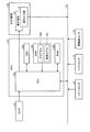
車両1には、車両1を制御する制御システムが設けられている。図8は、実施形態の制御システムの構成の一例を示すブロック図である。制御システムは、カメラ4、ソナーセンサ5、およびモニタ装置10のほかに、ECU12、シフトセンサ13、車輪速センサ14、および車内ネットワーク15を備える。車内ネットワーク15は、例えば、CAN(controller area network)として構成されている。ECU12、ソナーセンサ5、シフトセンサ13、および車輪速センサ14は、車内ネットワーク15に接続されている。カメラ4は、ECU12に接続されている。モニタ装置10は、ECU12と車内ネットワーク15とに接続されている。制御システムは、これらの他にも、アクセルセンサ、ブレーキシステム、または操舵システムなどを備え得る。
The vehicle 1 is provided with a control system that controls the vehicle 1. FIG. 8 is a block diagram showing an example of the configuration of the control system of the embodiment. The control system includes an ECU 12, a shift sensor 13, a wheel speed sensor 14, and an in-vehicle network 15, in addition to the camera 4, the
シフトセンサ13は、運転者が操作するシフトレバー11の位置を検出することによって、運転者によって選択されたレンジを検出する。
The shift sensor 13 detects the range selected by the driver by detecting the position of the
車輪速センサ14は、車輪3の単位時間当たりの回転数を検出するセンサであり、単位時間当たりの回転数を示す車輪速パルス数を検出情報として出力する。車輪速センサ14は、例えば4つの車輪3のそれぞれに設けられている。
The wheel speed sensor 14 is a sensor that detects the rotation speed of the
ソナーセンサ5、シフトセンサ13、および車輪速センサ14による検出情報は、車内ネットワーク15を介してECU12に送られる。ECU12は、各検出情報に応じて、エンジンユニット、操舵システム、またはブレーキシステム、等の制御を実行する。
Information detected by the
また、ECU12は、カメラ4が出力する画像を受け取ることができる。また、ECU12は、操作入力部9に入力された入力情報を、車内ネットワーク15を介して受け取ることができる。
The ECU 12 can also receive the image output by the camera 4. Further, the ECU 12 can receive the input information input to the
ECU12は、CPU(Central Processing Unit)12aと、SSD(Solid State Drive)12bと、ROM(Read Only Memory)12cと、RAM(Random Access Memory)12dと、を備える。CPU12a、ROM12c、およびRAM12dは、同一パッケージ内に集積されていてもよい。CPU12aは、任意のプログラムを実行することができるプロセッサであり、SSD12b、ROM12c、およびRAM12dは、任意のプログラムおよび任意のデータを保持することができるメモリである。即ち、ECU12は、コンピュータと同等のハードウェア構成を備えている。
The ECU 12 includes a CPU (Central Processing Unit) 12a, an SSD (Solid State Drive) 12b, a ROM (Read Only Memory) 12c, and a RAM (Random Access Memory) 12d. The CPU 12a, the ROM 12c, and the
ECU12は、実施形態の周辺監視装置の一例である。ROM12cは、プログラム100と、車両モデル101とを予め記憶する。CPU12aは、ROM12cに予め記憶されたプログラム100を読み出し、当該プログラム100を実行することによって周辺監視装置としての機能を実現する。RAM12dは、CPU12aでの演算で用いられる各種のデータを一時的に記憶する。SSD12bは、書き換え可能な不揮発性の記憶部であって、ECU12の電源がオフされた場合にあっても、CPU12aによって格納されたデータを維持することができる。プログラム100または車両モデル101は、SSD12bに予め記憶されてもよい。
The ECU 12 is an example of the peripheral monitoring device of the embodiment. The ROM 12c stores the
周辺監視装置としてのECU12は、カメラ4によって撮像された後方画像を利用して、周辺環境を示す画像を表示画面8に表示する。
The ECU 12 as the peripheral monitoring device uses the rear image captured by the camera 4 to display an image showing the peripheral environment on the
例えば、ECU12は、カメラ4から所定のフレームレートで出力されるそれぞれの後方画像を、取得した後に即時的に表示画面8に表示する。この表示方法を、ライブモードと表記する。図5に示される状態においては、バックパネル2aに設けられたカメラ4の撮像領域にトレーラ1000が入っている。このような場合、ECU12がライブモードで動作することにより、運転者は、車両1とトレーラ1000とのリアルタイムの位置関係を、表示画面8を介して把握することができる。なお、即時的に、とは、運転者がタイムラグを感じない程度に速やかに、という意味である。したがって、ライブモードにおいては、十分に高速な処理であれば、後方画像が取得されてから表示画面8に表示されるまでの間に当該後方画像に対して任意の画像処理が実行され得る。
For example, the ECU 12 immediately displays each rear image output from the camera 4 at a predetermined frame rate on the
ここで、カプラ1001とヒッチボール6とが近くなってくると、運転者は、位置合わせのために、カプラ1001とヒッチボール6との位置関係を確認する必要がある。しかしながら、カメラ4の撮像領域は少なくともバックパネル2aよりも後ろ側であるため、ヒッチボール6は、カメラ4の死角領域に位置する。よって、ECU12は、ライブモードではヒッチボール6を表示することができない。また、図7に示される状態においては、カプラ1001もカメラ4の死角領域に入るので、ECU12は、ライブモードではカプラ1001を表示することができない。よって、ライブモードでは、運転者は、表示画面8に表示されている内容に基づいて位置合わせを行うことが困難である。
Here, when the
また、図6に示されるようにバックパネル2aが開状態である場合には、カメラ4が地面方向を向くため、トレーラ1000がカメラ4の撮像領域から外れてしまう。このような場合、ECU12は、ライブモードでは、トレーラ1000を表示することができない。
Further, as shown in FIG. 6, when the
そこで、ECU12は、ライブモードのほかに過去画モードで動作することができるように構成されている。過去画モードは、カメラ4によって過去に撮像された後方画像を表示するモードである。また、過去画モードでは、運転者が周辺環境における車両1のリアルタイムの位置を確認できるように、ECU12は、過去に撮像された後方画像に車両1の位置を示す識別情報を重畳し、当該識別情報が重畳された後方画像を表示する。 Therefore, the ECU 12 is configured to be able to operate in the past image mode in addition to the live mode. The past image mode is a mode in which a rear image captured in the past by the camera 4 is displayed. In the past image mode, the ECU 12 superimposes identification information indicating the position of the vehicle 1 on the rear image captured in the past so that the driver can confirm the real-time position of the vehicle 1 in the surrounding environment, and the identification is performed. A rear image on which information is superimposed is displayed.
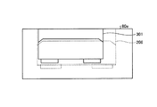
図9は、実施形態の表示画面8の表示内容の推移を示す図である。画像80aは、図5に示される状態において表示される表示内容であり、画像80bは、図6に示される状態において表示される表示内容であり、画像80cは、図7に示される状態において表示される表示内容である。画像80aは、ライブモードでの表示例であり、画像80bおよび画像80cは過去画モードでの表示例である。
FIG. 9 is a diagram showing a transition of display contents on the
画像80aには、トレーラ画像301が含まれている。トレーラ画像301は、カプラ1001の画像であるカプラ画像302を含んでいる。トレーラ画像301は、後方画像に含まれているものであり、実写画像である。即ち、トレーラ画像301は、カメラ4の撮像領域に入っている部分のみを示している。運転者は、表示画面8に表示されている画像80aを視認することによって、トレーラ1000と車両1との位置関係を判断することができる。なお、車両1の一部(例えばリアバンパーなど)がカメラ4の撮像領域に入っていてもよく、その場合はリアバンパーの画像が画像80aに含まれる。
The
なお、画像80aに、車両1の後端部からの距離を示すガイド線が重畳されて表示されてもよい。例えば、車両1の後端部から0.5m、1m、および1.5mの位置をそれぞれ示す3本のガイド線が画像80aに重畳されて表示されてもよい。
A guide line indicating the distance from the rear end of the vehicle 1 may be superimposed and displayed on the
画像80bには、カプラ画像302を含むトレーラ画像301が写っている。カプラ画像302を含むトレーラ画像301は、実写画像である。画像80bの元となっている過去に撮像された後方画像(以降、ベース画像という)は、バックパネル2aが閉状態であるときに撮像された後方画像であり、例えば、バックパネル2aが開状態にされる直前に撮像された後方画像である。
The
画像80bには、車両モデル画像201の一部である荷台モデル画像202がさらに表示されている。車両モデル画像201は、車両1の位置を示す識別情報の一例である。
In the image 80b, a loading
車両モデル画像201は、荷台2(より詳しくは荷台2の底部2b)の輪郭を模擬した形状を有する荷台モデル画像202と、後輪3Rの輪郭を模擬した形状を有する後輪モデル画像203と、ヒッチボールモデル画像204と、を含む。ヒッチボールモデル画像204は、ヒッチボール6のリアルタイムの位置を示すための識別情報であり、ここではその識別情報の一例として、ヒッチボール6の設置位置の輪郭を模擬した形状を有する。
The
ECU12は、車両1が移動すると、ベース画像の撮像領域内における移動後の車両1の位置と、ベース画像における車両モデル画像201の表示位置と、が対応するように、車両モデル画像201の表示位置を、逐次変更する。
When the vehicle 1 moves, the ECU 12 causes the display position of the
例えば画像80bにおいては、荷台モデル画像202のうちの一部のみが枠の下端に表示されている。これは、画像80bの表示タイミングにおいて、車両1の荷台2の底部2bのうちの後端の一部のみがベース画像の撮像領域に進入する程度に車両1とトレーラ1000とが離れていることを示している。
For example, in the image 80b, only part of the
なお、車両モデル画像201の表示様態は、特定の様態に限定されない。車両モデル画像201は、半透明化された様態で表示されてもよいし、輪郭を示す線のみが表示されてもよい。
The display mode of the
画像80cには、カプラ画像302を含むトレーラ画像301が写っている。画像80bのベース画像と画像80cのベース画像とは共通しており、カプラ画像302を含むトレーラ画像301は、画像80bと同じ様態で画像80cに表示されている。また、画像80cには、車両モデル画像201が重畳されている。
The
画像80cの場合、荷台モデル画像202の全体が表示されている。これは、画像80cの表示タイミングにおいては、ベース画像の撮像領域に車両1の荷台2の底部2bの全部が進入する程度まで車両1がトレーラ1000に近づいていることを示す。
In the case of the
また、画像80cには、車両モデル画像201に含まれるヒッチボールモデル画像204が表示されている。ヒッチボールモデル画像204は、ベース画像の撮像領域内におけるヒッチボール6のリアルタイムの位置を示している。ECU12は、過去に撮像された画像上にヒッチボール6のリアルタイムの位置を示すヒッチボールモデル画像204を重畳して表示画面8に表示するため、運転者は、カメラ4の死角領域に設けられているヒッチボール6のリアルタイムの位置を表示画面8を介して確認することができる。
Further, the
図10は、実施形態の周辺監視装置としてのECU12の機能的構成を示すブロック図である。CPU12aは、ROM12c内に予め格納されたプログラム100を実行することで、取得部120および画像処理部121として機能する。画像処理部121は、加工部123と、出力部124と、を備える。また、ECU12は、車両モデル101およびベース画像110を記憶する記憶部122を備える。記憶部122は、例えば、SSD12b、ROM12c、RAM12d、またはそれらの組み合わせによって実現される。
FIG. 10 is a block diagram showing a functional configuration of the ECU 12 as the peripheral monitoring device of the embodiment. The CPU 12a functions as the acquisition unit 120 and the image processing unit 121 by executing the
車両モデル101は、車両1の形状を示す3次元情報であり、車両モデル画像201を生成するための情報である。車両モデル101は、予め作成される。車両モデル101の詳細は後述する。
The
ベース画像110は、過去画モードにおいて使用される後方画像である。 The base image 110 is a rear image used in the past image mode.
取得部120は、カメラ4から出力される後方画像および車輪速センサ14から出力される検出情報を取得する。 The acquisition unit 120 acquires the rearward image output from the camera 4 and the detection information output from the wheel speed sensor 14.
画像処理部121は、取得部120によって取得された各情報に基づいて、表示画面8の表示を制御する。
The image processing unit 121 controls the display of the
具体的には、ライブモードが設定されている場合には、出力部124は、カメラ4から取得した後方画像を、その後方画像を取得したタイミングの後に即時的に表示画面8に出力する。
Specifically, when the live mode is set, the output unit 124 immediately outputs the rear image acquired from the camera 4 to the
過去画モードが設定されている場合には、画像処理部121は、過去のタイミングに取得された後方画像をベース画像110に設定し、加工部123は、ベース画像110に現在のタイミングにおける車両1の位置を示す車両モデル画像201を重畳する。出力部124は、ベース画像110に車両モデル画像201が重畳されて生成された画像を表示画面8に出力する。画像処理部121は、ここでは一例として、ライブモードから過去画モードに遷移したタイミングで、そのときに取得した後方画像をベース画像110として記憶部122に保存する。
When the past image mode is set, the image processing unit 121 sets the rear image acquired at the past timing in the base image 110, and the processing unit 123 sets the base image 110 in the vehicle 1 at the present timing. The
車両モデル画像201の生成方法は、特定の方法に限定されない。車両モデル画像201の生成方法の一例を以下に説明する。
The method of generating the
加工部123は、3次元の仮想空間を設定し、ベース画像110が取得された際に、車両モデル101と仮想視点402とを仮想空間400に配置する。
The processing unit 123 sets a three-dimensional virtual space and arranges the
図11は、車両モデル101および仮想視点402の実施形態の配置の一例を示す図である。
FIG. 11 is a diagram showing an example of the arrangement of the
仮想空間400において、地面に対応する平面401に車両モデル101が配置されている。車両モデル101は、荷台2の底部2bの輪郭を模した形状を有する荷台モデル102と、後輪3Rの輪郭を模した形状を有する後輪モデル103と、ヒッチボール6の設置位置の輪郭を模した形状を有するヒッチボールモデル104と、を備える。荷台モデル102、後輪モデル103、およびヒッチボールモデル104の位置関係は、実際の車両1における荷台2の底部2b、後輪3R、およびヒッチボール6の設置位置の位置関係と対応する。
In the
また、車両モデル101を基準とした仮想視点402の位置は、車両1を基準としたカメラ4の位置と対応する。また、車両モデル101を基準とした仮想視点402の向きは、車両モデル101を基準としたカメラ4の向きと等しい。また、仮想視点402の画角は、カメラ4の画角と等しい。よって、仮想視点402からの視界は、カメラ4からの視界と対応する。
Further, the position of the
加工部123は、車両1の移動後、ベース画像110が撮像されたタイミングを基準とした車両1の移動量を演算する。加工部123は、車輪3毎の車輪速パルス数を積分することによって車両1の移動量を演算する。移動量は、向き情報を含むベクトル量である。加工部123は、仮想視点402の位置を仮想空間400内に固定したまま、車両モデル101を演算された移動量に対応する量だけ初期位置から移動させる。そして、加工部123は、仮想視点402を用いた視点変換によって、車両モデル画像201を生成する。
The processing unit 123 calculates the amount of movement of the vehicle 1 with reference to the timing at which the base image 110 was captured after the movement of the vehicle 1. The processing unit 123 calculates the movement amount of the vehicle 1 by integrating the number of wheel speed pulses for each
視点変換とは、仮想視点402を視点とする透視投影によって、仮想視点402からの視界を示す画像を得ることである。仮想視点402からの視界を示す画像は、枠を有している。仮想視点402からの視界は、ベース画110像の撮像時のカメラ4の視界に対応するので、仮想視点402からの視界を示す画像の枠は、ベース画像110の枠に対応する。仮想視点402からの視界内に車両モデル101が存在する場合には、枠内に車両モデル画像201が含まれる。
The viewpoint conversion is to obtain an image showing the field of view from the
加工部123は、車両モデル画像201をベース画像110に重畳する際には、車両モデル101が投影された2次元平面の枠とベース画像110の枠とを位置合わせする。これにより、車両モデル画像201は、ベース画像110における、車両1のリアルタイムの位置を示す位置に重畳される。同様に、ヒッチボールモデル画像204は、ベース画像110における、ヒッチボール6のリアルタイムの位置を示す位置に重畳される。
When superimposing the
なお、移動量の演算方法は、車輪速パルス数を用いた方法だけに限定されない。移動量の演算方法の別の例として、カメラ4が出力する画像に基づいて移動量を演算する方法が採用可能である。具体的には、撮像されたタイミングが異なる2枚の画像を用いてオプティカルフローを演算し、演算されたオプティカルフローに基づいて画像を撮像したタイミング間の車両1の移動量を演算することが可能である。このような方法によって、加工部123は、逐次取得した後方画像から車両1の移動量を演算してもよい。 The method of calculating the movement amount is not limited to the method using the wheel speed pulse number. As another example of the method of calculating the movement amount, a method of calculating the movement amount based on the image output by the camera 4 can be adopted. Specifically, it is possible to calculate the optical flow by using two images having different captured timings, and calculate the movement amount of the vehicle 1 between the timings of capturing the images based on the calculated optical flow. Is. By such a method, the processing unit 123 may calculate the movement amount of the vehicle 1 from the rear images sequentially acquired.
次に、以上のように構成された実施形態の周辺監視装置の動作について説明する。図12は、実施形態の周辺監視装置としてのECU12の動作を説明するためのフローチャートである。 Next, an operation of the perimeter monitoring device of the embodiment configured as described above will be described. FIG. 12 is a flowchart for explaining the operation of the ECU 12 as the peripheral monitoring device of the embodiment.
画像処理部121は、表示開始のタイミングに至ったか否かを判断する(S101)。 The image processing unit 121 determines whether or not the display start timing has been reached (S101).
表示開始のタイミングの判断方法は、特定の方法に限定されない。一例では、運転者によってシフトレバー11がリバースレンジに入れられたとき、シフトセンサ13がリバースレンジが選択された旨を検知し、ECU12に通知する。取得部120が当該通知を受けると、画像処理部121は、表示開始のタイミングに至ったと判断する。
The method of determining the display start timing is not limited to a particular method. In one example, when the driver puts the
別の例では、画像処理部121は、表示画面8に表示開始の入力を促すボタンを表示する。そして、運転者が当該ボタンをタッチすると、操作入力部9が、その旨を検知してECU12に通知する。取得部120は、当該通知を、表示開始の操作入力として受信する。画像処理部121は、取得部120が表示開始の操作入力を受信すると、表示開始のタイミングに至ったと判断する。
In another example, the image processing unit 121 displays a button on the
画像処理部121は、表示開始のタイミングに至っていないと判断した場合(S101、No)、S101の処理を再び実行する。 When determining that the display start timing has not come (S101, No), the image processing unit 121 executes the process of S101 again.
画像処理部121によって表示開始のタイミングに至ったと判断された場合(S101、Yes)、取得部120は、カメラ4から出力された後方画像を取得する(S102)。すると、出力部124は、S102によって取得された後方画像を即時的に表示画面8に出力する(S103)。 When the image processing unit 121 determines that the display start timing has been reached (S101, Yes), the acquisition unit 120 acquires the rear image output from the camera 4 (S102). Then, the output unit 124 immediately outputs the rearward image acquired in S102 to the display screen 8 (S103).
続いて、画像処理部121は、モード切り替えのタイミングに至ったか否かを判断する(S104)。画像処理部121は、モード切り替えのタイミングに至っていないと判断した場合(S104、No)、S102〜S103の処理を再び実行し、その後、S104の処理を再び実行する。 Then, the image processing unit 121 determines whether or not the timing for mode switching has been reached (S104). When the image processing unit 121 determines that the timing of mode switching has not been reached (S104, No), the processes of S102 to S103 are executed again, and then the process of S104 is executed again.
S102およびS103の処理は、ライブモードでの動作に該当する。S102からS104、Noまでのループ処理は、制御がこのループ処理を抜けるまで、短い周期で繰り返し実行される。制御がこのループ処理を抜けるまで、ライブモードでの動作が継続される。 The processing of S102 and S103 corresponds to the operation in the live mode. The loop processing from S102 to S104, No is repeatedly executed in a short cycle until the control exits this loop processing. The operation in the live mode is continued until the control exits this loop processing.
モード切り替えのタイミングの判断方法は、特定の方法に限定されない。一例では、取得部120は、運転者によるモード切り替えの操作入力を取得し、画像処理部121は、モード切り替えの操作入力に基づいてモード切り替えのタイミングを判断する。具体的には、例えば、画像処理部121は、表示画面8に、モードの切り替えの入力を促すボタンを表示する。運転者によって当該ボタンがタッチされると、操作入力部9は、当該ボタンがタッチされた旨を検知し、ECU12に通知する。取得部120は、当該通知を、モード切り替えの操作入力として受信する。画像処理部121は、取得部120がモード切り替えの操作入力を受信すると、モード切り替えのタイミングに至ったと判断する。
The method of determining the timing of mode switching is not limited to a particular method. In one example, the acquisition unit 120 acquires a mode switching operation input by the driver, and the image processing unit 121 determines the mode switching timing based on the mode switching operation input. Specifically, for example, the image processing unit 121 displays a button on the
別の例では、取得部120が運転者による変速機構のレンジを切り替える操作入力を取得し、画像処理部121は、変速機構のレンジをリバースレンジから他のレンジに切り替える操作入力に基づいてモード切り替えのタイミングを判断する。運転者は、例えば、図5に示される状態から車両1の後退を開始し、その後、車両1を停止させて車両1を降りて、バックパネル2aを手動で閉状態から開状態にする。運転者が、車両1を停止させるためにシフトレバー11をリバースレンジからパーキングレンジに入れたとき、シフトセンサ13がパーキングレンジが選択された旨を検知し、ECU12に通知する。取得部120は、その通知を、変速機構のレンジをリバースレンジから他のレンジに切り替える操作入力として受信する。画像処理部121は、取得部120が変速機構のレンジをリバースレンジから他のレンジに切り替える操作入力を受信すると、モード切り替えのタイミングに至ったと判断する。なお、切り替え後のレンジは必ずしもパーキングレンジでなくてもよい。
In another example, the acquisition unit 120 acquires an operation input for switching the range of the transmission mechanism by the driver, and the image processing unit 121 switches the mode based on the operation input for switching the range of the transmission mechanism from the reverse range to another range. To determine the timing. For example, the driver starts the retreat of the vehicle 1 from the state shown in FIG. 5, then stops the vehicle 1, dismounts the vehicle 1, and manually changes the
さらに別の例では、取得部120は、バックパネル2aを開状態にする操作入力を取得し、画像処理部121は、バックパネル2aを開状態にする操作入力に基づいてモード切り替えのタイミングを判断する。具体的には、例えば、バックパネル2aのヒンジにセンサが設けられる。当該センサは、バックパネル2aが閉状態から開状態になったとき、その旨を検知し、ECU12に通知する。取得部120は、その通知を、バックパネル2aを開状態にする操作入力として受信する。画像処理部121は、取得部120がバックパネル2aを開状態にする操作入力を受信すると、モード切り替えのタイミングに至ったと判断する。
In yet another example, the acquisition unit 120 acquires an operation input for opening the
バックパネル2aを開状態にする操作入力の検知方法は、バックパネル2aのヒンジに設けられたセンサによって検知する方法だけに限定されない。例えば、車両1の室内または室外に設けられた操作部の操作によって、バックパネル2aが開閉可能に構成される場合がある。その場合、取得部120は、バックパネル2aを開状態にする操作入力を、当該操作部を介して取得することができる。
The method of detecting the operation input for opening the
さらに別の例では、取得部120は、ソナーセンサ5から検出情報を取得し、画像処理部121は、ソナーセンサ5からの検出情報に基づいてモード切り替えのタイミングを判断する。具体的には、例えば、画像処理部121は、ソナーセンサ5からの検出情報を逐次取得する。それぞれの検出情報は、車両1からトレーラ1000までのリアルタイムの距離を示す。画像処理部121は、車両1からトレーラ1000までのリアルタイムの距離を、しきい値と比較し、当該距離がしきい値を下回った場合に、モード切り替えのタイミングに至ったと判断する。カプラ1001がバックパネル2aに衝突せずかつカプラ1001がバックパネル2aの開閉動作に干渉しない最短の距離よりも大きい値が、判断のためのしきい値として使用される。しきい値は、例えば予め設定される。
In yet another example, the acquisition unit 120 acquires the detection information from the
画像処理部121は、モード切り替えのタイミングに至ったと判断した場合(S104、Yes)、ECU12は、過去画モードでの動作を開始する。 When the image processing unit 121 determines that the timing for mode switching has been reached (S104, Yes), the ECU 12 starts the operation in the past image mode.
具体的には、まず、取得部120は、カメラ4が撮像した後方画像を取得する(S105)。すると、画像処理部121は、S105によって取得された後方画像をベース画像110として記憶部122に保存する(S106)。 Specifically, first, the acquisition unit 120 acquires the rear image captured by the camera 4 (S105). Then, the image processing unit 121 stores the rearward image acquired in S105 in the storage unit 122 as the base image 110 (S106).
続いて、加工部123は、車両モデル101および仮想視点402を仮想空間400に配置する(S107)。例えば図11を用いて説明したように、S107では、加工部123は、車両モデル101を仮想空間400に配置し、加工部123は、カメラ4の設置位置に対応する位置に、仮想視点402を配置する。
Subsequently, the processing unit 123 arranges the
続いて、加工部123は、仮想視点402からの透視投影によって、車両モデル画像201を生成する(S108)。
Subsequently, the processing unit 123 generates the
出力部124は、記憶部122からベース画像110を読み出して、読み出したベース画像110に車両モデル画像201を重畳し、車両モデル画像201が重畳されたベース画像110を表示画面8に表示する(S109)。
The output unit 124 reads the base image 110 from the storage unit 122, superimposes the
続いて、画像処理部121は、表示終了のタイミングに至ったか否かを判断する(S110)。 Subsequently, the image processing unit 121 determines whether or not the display end timing has been reached (S110).
表示終了のタイミングの判断方法は、特定の方法に限定されない。画像処理部121は、表示開始のタイミングと同様に、操作入力部9に入力された操作入力に基づいて表示終了のタイミングを判断してもよいし、変速機構のレンジを切り替える操作入力に基づいて表示終了のタイミングを判断してもよい。
The method of determining the display end timing is not limited to a particular method. The image processing unit 121 may determine the display end timing based on the operation input input to the
表示終了のタイミングに至っていないと画像処理部121によって判断された場合(S110、No)、取得部120は、車輪速パルス数を取得する(S111)。そして、加工部123は、車輪速パルス数に基づいて、車両1の移動量を演算する(S112)。移動量は、車輪速パルス数の積分によって得られる。 When the image processing unit 121 determines that the display end timing has not come (S110, No), the acquisition unit 120 acquires the number of wheel speed pulses (S111). Then, the processing unit 123 calculates the movement amount of the vehicle 1 based on the wheel speed pulse number (S112). The amount of movement is obtained by integrating the number of wheel speed pulses.
なお、S108からS110、Noを経てS113に至るまでの処理は、ループ処理を構成する。即ち、S112の処理は、制御がこのループ処理を抜けるまで、繰り返し実行される。2回目以降のループ処理の場合、加工部123は、S112において、前回にS112を実行したタイミングからの車両1の移動量を演算する。1回目のループ処理の場合、加工部123は、S112において、ベース画像が取得されてからの車両1の移動量を演算する。 The processes from S108 to S110, through No to S113 form a loop process. That is, the process of S112 is repeatedly executed until the control exits this loop process. In the case of the second and subsequent loop processing, in S112, the processing unit 123 calculates the movement amount of the vehicle 1 from the timing when S112 was executed last time. In the case of the first loop processing, the processing unit 123 calculates the amount of movement of the vehicle 1 after the base image is acquired in S112.
S112の処理の後、加工部123は、仮想空間400上の車両モデル101の位置を移動量に応じて変更する(S113)。例えば、車両1がある移動量だけ後退した場合、加工部123は、仮想空間400内において、対応する量だけ車両モデル101を後退させる。
After the processing of S112, the processing unit 123 changes the position of the
そして、制御がS108に移行し、加工部123は、S108において、車両モデル画像201を再び作成する。
Then, the control shifts to S108, and the processing unit 123 recreates the
S110において、表示終了のタイミングに至ったと画像処理部121によって判断された場合(S110、Yes)、動作が終了する。 If the image processing unit 121 determines in S110 that the display end timing has been reached (S110, Yes), the operation ends.
S108からS110、Noを経てS113に至るまでループ処理は、短い周期で繰り返し実行される。その結果として、画像処理部121は、同じベース画像110を表示し、ヒッチボールモデル画像204を、ヒッチボール6のリアルタイムの位置の移動に対応するように、そのベース画像110上で移動させることができる。即ち、ベース画像110上のヒッチボールモデル画像204の位置は、常にヒッチボール6のリアルタイムの位置を示す。
The loop process from S108 to S110, through No to S113 is repeatedly executed in a short cycle. As a result, the image processing unit 121 displays the same base image 110 and can move the
以上述べたように、実施形態では、周辺監視装置は、過去(第1のタイミング)に取得した後方画像に、ヒッチボール6の第1のタイミングの後のリアルタイム(第2のタイミング)の位置を示す識別情報であるヒッチボールモデル画像204を重畳し、ヒッチボールモデル画像204が重畳された後方画像を表示画面8に表示する。
As described above, in the embodiment, the periphery monitoring device sets the real-time (second timing) position after the first timing of the hitchball 6 in the rear image acquired in the past (first timing). The
これにより、ヒッチボール6がカメラ4の死角領域に位置する場合であっても、表示画面8にヒッチボール6のリアルタイムの位置を示す識別情報が表示され、その結果、運転者は、表示画面8を介してヒッチボール6の位置を確認することが可能となる。よって、実施形態の周辺監視装置は、連結装置間の位置合わせを行いやすくすることができる。
As a result, even when the hitch ball 6 is located in the blind spot area of the camera 4, identification information indicating the real-time position of the hitch ball 6 is displayed on the
なお、以上では、ヒッチボール6が荷台2の底部2bに設けられており、ヒッチボール6はカメラ4の死角領域に位置する、として説明した。ヒッチボール6が設けられる位置は荷台2の底部2bでなくてもよい。また、ヒッチボール6は、カメラ4の撮像領域内に設置されている場合であっても、実施形態の技術は適用可能である。
In the above description, the hitch ball 6 is provided in the
例えば、ヒッチボール6がリアバンパー近傍に設けられ、Vノーズタイプのトレーラがそのヒッチボール6を介して連結される。そのような場合、バックパネル2aに設けられたカメラ4の撮像領域にヒッチボール6が入り得る。しかしながら、位置合わせを行う際、車両1とトレーラとの距離が近づくにつれてカメラ4の撮像領域の光量が減少することで、ヒッチボール6を含む各種対象物の写りが不明瞭となる場合がある。周辺監視装置は、撮像領域の光量が十分に確保されていた過去のタイミングに撮像された後方画像をベース画像110として用い、ヒッチボールモデル画像204をベース画像110に重畳して表示することによって、ヒッチボール6のリアルタイムの位置をわかりやすく表示することが可能になる。
For example, a hitch ball 6 is provided near the rear bumper, and a V nose type trailer is connected via the hitch ball 6. In such a case, the hitch ball 6 may enter the imaging area of the camera 4 provided on the
なお、周辺監視装置は、カプラ1001の先端から地面まで延伸する識別情報をベース画像110にさらに重畳してもよい。
The perimeter monitoring device may further superimpose the identification information extending from the tip of the
図13は、実施形態の表示画面8の別の表示例を示す図である。画像80dは、過去画モードでの表示例を示している。画像80dには、画像80bと同様に、カプラ画像302を含むトレーラ画像301が写っている。カプラ画像302を含むトレーラ画像301は、ベース画像に含まれているものであり、実写画像である。画像80dには、カプラ画像302の先端を示す位置からカプラ1001の先端の直下の地面を示す位置まで延伸する円柱を模したオブジェクト画像205が重畳されている。運転者は、表示画面8を介してオブジェクト画像205を視認することにより、カプラ1001の先端の高さ情報を直感的に認識することが可能となる。
FIG. 13 is a diagram showing another display example of the
オブジェクト画像205の表示方法は特定の方法に限定されない。一例では、後方の周辺環境の3次元データを測定可能な測定装置が車両1に設けられ、取得部120は、当該測定装置からの測定結果を取得する。測定装置は、例えばステレオカメラまたはレーザレンジスキャナである。加工部123は、取得された測定結果に基づいて、車両1からカプラ1001までの距離および方向と、カプラ1001の先端の高さとを演算する。そして、加工部123は、仮想空間400内の対応する位置に、カプラ1001の先端の高さに対応する長さの円柱状のオブジェクトを配置する。そして、加工部123は、車両モデル101から車両モデル画像201を演算する場合と同様に、オブジェクトを仮想視点402を視点とする二次元平面に投影することによって、オブジェクト画像205を生成する。
The display method of the
3次元データからカプラ1001を識別する方法は、特定の方法に限定されない。一例では、画像処理部121は、表示画面8にベース画像110を表示し、運転者は、操作入力部9をタッチすることにより、ベース画像110内のカプラ1001が写っている部分を指示する。加工部123は、タッチされた位置と、ベース画像110が撮像されたタイミングと略同じタイミングで測定装置から得られた3次元データと、を対比することにより、3次元データ内においてカプラ1001に相当する部分を特定する。別の例では、加工部123は、カプラ1001の画像を記憶部122などに予め記憶しておき、カプラ1001の画像を用いたパターンマッチングによって、ベース画像110内のカプラ1001が写っている部分を特定する。そして、加工部123は、ベース画像110内の特定した部分と、ベース画像110が撮像されたタイミングと略同じタイミングで測定装置から得られたリアルタイムの3次元データと、を対比することにより、3次元データ内においてカプラ1001に相当する部分を特定する。
The method of identifying the
このように、周辺監視装置は、種々の方法でオブジェクト画像205を生成することが可能である。なお、カプラ1001の先端から地面まで延伸する識別情報の表示様態は、円柱の形状を模したオブジェクト画像205だけに限定されない。例えば、カプラ1001の先端から地面まで延伸する識別情報は、線形状を有していてもよい。
In this way, the perimeter monitoring device can generate the
また、周辺監視装置は、過去画モードのほかに、ライブモードで動作することができる。周辺監視装置は、ライブモードでは、取得した後方画像を、取得したタイミングの後に即時的に表示画面8に表示する。周辺監視装置がライブモードで動作することにより、運転者は、カメラ4の撮像領域内の状態をリアルタイムの実写画像によって確認することが可能である。
In addition to the past image mode, the peripheral monitoring device can operate in the live mode. In the live mode, the periphery monitoring device immediately displays the acquired rear image on the
また、周辺監視装置は、モード切り替えの操作入力、または変速機構のレンジをリバースレンジから他のレンジに切り替える操作入力、またはバックパネル2aを閉状態から開状態にする操作入力、または測距装置としてのソナーセンサ5からの検出情報、に基づいて、ライブモードから過去画モードに遷移する。このように、周辺監視装置は、種々の事象をトリガとしてモード間の遷移を行うことができる。
In addition, the peripheral monitoring device is a mode switching operation input, an operation input for switching the range of the transmission mechanism from the reverse range to another range, an operation input for changing the
なお、以上では、モード切り替えの際に取得された後方画像がベース画像110として設定される、として説明した。ベース画像110の選択方法はこれに限定されない。例えば、画像処理部121は、逐次取得される後方画像を例えば記憶部122に時系列順に蓄積する。そして、画像処理部121は、記憶部122に蓄積された複数の後方画像から、カプラ画像302が含まれている、最後に取得された後方画像を選択する。そして、画像処理部121は、選択した後方画像をベース画像110として設定する。後方画像にカプラ画像302が含まれているか否かは、例えばパターンマッチングなどによって判断可能である。画像処理部121は、逐次取得される後方画像にカプラ画像302が含まれているか否かを後方画像が取得される度に判断し、判断結果が、後方画像にカプラ画像302が含まれている状態から後方画像にカプラ画像302が含まれていない状態に変化したとき、自動でライブモードから過去画モードに遷移してもよい。
In the above description, the rear image acquired when the mode is switched is set as the base image 110. The selection method of the base image 110 is not limited to this. For example, the image processing unit 121 accumulates sequentially acquired rearward images in the storage unit 122 in chronological order. Then, the image processing unit 121 selects the last acquired rear image including the
または、画像処理部121は、モード切り替えのタイミングから所定時間だけ遡ったタイミングで取得された後方画像をベース画像110として設定してもよい。 Alternatively, the image processing unit 121 may set, as the base image 110, a rear image acquired at a timing that is traced back a predetermined time from the timing of mode switching.
また、以上では、車両モデル101は、ヒッチボールモデル104のほかに、荷台モデル102、後輪モデル103を含む、として説明した。車両モデル101は、ヒッチボールモデル104を含んでいればよい。例えば、車両モデル101から荷台モデル102は省略することが可能である。また、車両モデル101から後輪モデル103は省略することが可能である。車両モデル101として、車両1の形状をリアルに示す3次元モデルが採用可能である。車両モデル101の3次元形状の表現方法は、特定の方法に限定されない。例えば、ポリゴンモデル、ワイヤーフレームモデル、またはソリッドモデルによって、車両モデル101の3次元形状が表現され得る。
Further, in the above description, the
また、周辺監視装置は、過去画モードからライブモードに遷移可能に構成されてもよい。荷台2がカプラ1001の真下に入った後、バックパネル2aを閉状態にすることが可能である。例えば、運転者は、荷台2がカプラ1001の真下に入った後、過去画モードからライブモードに切り替えてもよい。
Further, the peripheral monitoring device may be configured to be able to transit from the past image mode to the live mode. It is possible to close the
なお、荷台2がカプラ1001の真下に入った後に過去画モードからライブモードに切り替えられた場合、表示画面8にはヒッチボール6もカプラ1001も表示されないので、そのままでは運転者は位置合わせを行うことが困難である。周辺監視装置は、下記の位置合わせ完了時のトレーラ画像301を予め記憶しておき、過去画モードからライブモードに戻った後、ライブモードでの画像に、位置合わせ完了時のトレーラ画像301を重畳して表示してもよい。位置合わせ完了時のトレーラ画像301は、例えば、過去に連結作業が行われた際に撮像されて保存されたものである。
When the
周辺監視装置は、運転者による実写画像の視認を妨げないように、重畳の前に、位置合わせ完了時のトレーラ画像301に対し、種々の画像処理を行う。一例では、周辺監視装置は、位置合わせ完了時のトレーラ画像301に対し、輪郭抽出を行い、抽出された輪郭を表示する。図14は、実施形態の表示画面8のさらに別の表示例を示す図である。この例では、画像80eには、トレーラ画像301の輪郭206が点線で示されている。運転者は、実写のトレーラ画像301と輪郭206とが一致するように車両1を運転することによって、位置合わせを行うことができる。
The surroundings monitoring device performs various image processing on the
また、周辺監視装置は、ヒッチボール6とカプラ1001との距離に応じて車両モデル画像201の表示様態を変更してもよい。例えば、周辺監視装置は、ヒッチボール6とカプラ1001との距離が予め設定されたしきい値よりも大きい場合、ヒッチボールモデル画像204を青色に着色して表示し、ヒッチボール6とカプラ1001との距離が当該しきい値よりも小さい場合、ヒッチボールモデル画像204を赤色に着色して表示する。表示様態の変更方法は、これに限定されない。例えば、周辺監視装置は、距離が当該しきい値よりも小さくなったときに、非点滅表示から点滅表示に変更したり、あるいはその逆の変更を行うことができる。別の例では、周辺監視装置は、距離が当該しきい値よりも大きい場合、荷台モデル画像202、後輪モデル画像203、およびヒッチボールモデル画像204を表示し、距離が当該しきい値よりも小さくなった場合、車両モデル画像201のうちのヒッチボールモデル画像204のみを表示する。
Further, the periphery monitoring device may change the display mode of the
また、周辺監視装置は、ヒッチボール6とカプラ1001との位置合わせが完了する位置までの経路を任意のタイミングで演算し、演算された経路で車両1が移動するように、舵角を制御してもよい。これにより、運転者は、アクセルペダルとブレーキペダルとを操作するだけで、位置合わせを行うことが可能となる。さらに、周辺監視装置は、演算された経路で車両1が移動するように、加減速を自動で行うように構成されてもよい。
In addition, the periphery monitoring device calculates a route up to a position where the hitch ball 6 and the
なお、以上では、取得部120、加工部123、および出力部124は、CPU12aがプログラム100を実行することによって実現される、として説明した。取得部120、加工部123、および出力部124のうちの一部または全部は、ハードウェア回路によって実現されてもよい。
In the above description, the acquisition unit 120, the processing unit 123, and the output unit 124 have been described as being realized by the CPU 12a executing the
また、プログラム100は、コンピュータにインストール可能な形式又は実行可能な形式のファイルでCD−ROM、フレキシブルディスク(FD)、CD−R、DVD(Digital Versatile Disk)、またはフラッシュメモリ等の、コンピュータで読み取り可能な記録媒体に記録されて提供され得る。
The
また、プログラム100は、インターネット等のネットワークに接続されたコンピュータ上に格納し、ネットワーク経由でダウンロードさせることにより提供するように構成してもよい。また、プログラム100は、インターネット等のネットワーク経由で提供または配布され得る。
The
また、プログラム100は、ROM12c等に予め組み込んで提供され得る。
Further, the
同様に、車両モデル101は、CD−ROM、FD、CD−R、DVD、またはフラッシュメモリ等の、コンピュータで読み取り可能な記録媒体に記録されて提供され得る。また、車両モデル101は、インターネット等のネットワークに接続されたコンピュータ上に格納し、ネットワーク経由でダウンロードさせることにより提供するように構成してもよい。また、車両モデル101は、インターネット等のネットワーク経由で提供または配布され得る。
Similarly,
以上、本発明の実施形態を例示したが、上記実施形態および変形例はあくまで一例であって、発明の範囲を限定することは意図していない。上記実施形態や変形例は、その他の様々な形態で実施されることが可能であり、発明の要旨を逸脱しない範囲で、種々の省略、置き換え、組み合わせ、変更を行うことができる。また、各実施形態や各変形例の構成や形状は、部分的に入れ替えて実施することも可能である。 Although the embodiments of the present invention have been illustrated above, the above embodiments and modifications are merely examples, and are not intended to limit the scope of the invention. The above-described embodiment and modified examples can be implemented in various other forms, and various omissions, replacements, combinations, and changes can be made without departing from the spirit of the invention. Further, the configurations and shapes of the embodiments and the modified examples may be partially replaced with each other.
1…車両、2…荷台、2a…バックパネル、2b…底部、3…車輪、3F…前輪、3R…後輪、4…カメラ、5…ソナーセンサ、6…ヒッチボール、8…表示画面、9…操作入力部、10…モニタ装置、11…シフトレバー、12…ECU、12a…CPU、12b…SSD、12c…ROM、12d…RAM、13…シフトセンサ、14…車輪速センサ、15…車内ネットワーク、80a,80b,80c,80d,80e…画像、100…プログラム、101…車両モデル、102…荷台モデル、103…後輪モデル、104…ヒッチボールモデル、110…ベース画像、120…取得部、121…画像処理部、122…記憶部、123…加工部、124…出力部、201…車両モデル画像、202…荷台モデル画像、203…後輪モデル画像、204…ヒッチボールモデル画像、205…オブジェクト画像、206…輪郭、301…トレーラ画像、302…カプラ画像、400…仮想空間、401…平面、402…仮想視点、1000…トレーラ、1001…カプラ 1... Vehicle, 2... Loading platform, 2a... Back panel, 2b... Bottom part, 3... Wheel, 3F... Front wheel, 3R... Rear wheel, 4... Camera, 5... Sonar sensor, 6... Hitch ball, 8... Display screen, 9... Operation input unit, 10... Monitor device, 11... Shift lever, 12... ECU, 12a... CPU, 12b... SSD, 12c... ROM, 12d... RAM, 13... Shift sensor, 14... Wheel speed sensor, 15... In-vehicle network, 80a, 80b, 80c, 80d, 80e... Image, 100... Program, 101... Vehicle model, 102... Luggage model, 103... Rear wheel model, 104... Hitchball model, 110... Base image, 120... Acquisition part, 121... Image processing unit, 122... Storage unit, 123... Processing unit, 124... Output unit, 201... Vehicle model image, 202... Packing model image, 203... Rear wheel model image, 204... Hitchball model image, 205... Object image, 206... Outline, 301... Trailer image, 302... Coupler image, 400... Virtual space, 401... Plane, 402... Virtual viewpoint, 1000... Trailer, 1001... Coupler
Claims (5)
前記第1のタイミングよりも後の第2のタイミングにおいて、前記第1の連結装置の前記第2のタイミングの位置を示す第1の識別情報を前記第1の後方画像に重畳し、前記第1の識別情報が重畳された前記第1の後方画像を前記車両の室内に設けられた表示画面に表示する画像処理部と、
を備えた周辺監視装置。 An acquisition unit that acquires a first rear image of the vehicle having a first connecting device for connecting the towed vehicle at a first timing;
At a second timing after the first timing, the first identification information indicating the position of the second timing of the first connecting device is superimposed on the first rear image, An image processing unit configured to display the first rear image on which the identification information of is superimposed on a display screen provided in the vehicle interior,
Surrounding monitoring device.
前記第1の連結装置は、前記撮像装置の死角領域に設けられ、
前記取得部は、前記車両に設けられた撮像装置から前記第1の後方画像を取得する、
請求項1に記載の周辺監視装置。 An imaging device is provided in the vehicle,
The first coupling device is provided in a blind spot area of the imaging device,
The acquisition unit acquires the first rear image from an imaging device provided in the vehicle,
The surroundings monitoring device according to claim 1.
請求項1または2に記載の周辺監視装置。 The image processing unit further superimposes, on the first rear image, second identification information extending from a tip of a second connecting device that is connected to the first connecting device provided on the towed vehicle to the ground. To do
The perimeter monitoring device according to claim 1 or 2.
前記画像処理部は、前記取得された第2の後方画像を前記表示画面に前記第3のタイミングの後に即時的に表示し、
前記第3のタイミングは、第1モードで動作中のタイミングであり、
前記第2のタイミングは、前記第1モードと異なる第2モードで動作中のタイミングである、
請求項1から3の何れか1項に記載の周辺監視装置。 The acquisition unit acquires a second rear image at a third timing,
The image processing unit immediately displays the acquired second rear image on the display screen after the third timing,
The third timing is a timing during operation in the first mode,
The second timing is a timing during operation in a second mode different from the first mode,
The perimeter monitoring device according to any one of claims 1 to 3.
前記取得されたいずれかの操作入力または検出情報に基づいて前記第1モードから前記第2モードに遷移する、
請求項4に記載の周辺監視装置。 The acquisition unit is a mode switching operation input, an operation input for switching the range of the transmission mechanism of the vehicle from the reverse range to another range, an operation input for changing the tailgate from a closed state to an open state, or provided on the vehicle. Acquiring detection information from a distance measuring device that detects the distance between the vehicle and the towed vehicle,
Transitioning from the first mode to the second mode based on any of the acquired operation input or detection information,
The perimeter monitoring device according to claim 4.
Priority Applications (3)
| Application Number | Priority Date | Filing Date | Title |
|---|---|---|---|
| JP2017005097A JP6729409B2 (en) | 2017-01-16 | 2017-01-16 | Perimeter monitoring device |
| PCT/JP2017/039196 WO2018131263A1 (en) | 2017-01-16 | 2017-10-30 | Periphery monitoring device |
| US16/477,919 US11260794B2 (en) | 2017-01-16 | 2017-10-30 | Periphery monitoring device |
Applications Claiming Priority (1)
| Application Number | Priority Date | Filing Date | Title |
|---|---|---|---|
| JP2017005097A JP6729409B2 (en) | 2017-01-16 | 2017-01-16 | Perimeter monitoring device |
Publications (2)
| Publication Number | Publication Date |
|---|---|
| JP2018117176A JP2018117176A (en) | 2018-07-26 |
| JP6729409B2 true JP6729409B2 (en) | 2020-07-22 |
Family
ID=62839336
Family Applications (1)
| Application Number | Title | Priority Date | Filing Date |
|---|---|---|---|
| JP2017005097A Active JP6729409B2 (en) | 2017-01-16 | 2017-01-16 | Perimeter monitoring device |
Country Status (3)
| Country | Link |
|---|---|
| US (1) | US11260794B2 (en) |
| JP (1) | JP6729409B2 (en) |
| WO (1) | WO2018131263A1 (en) |
Families Citing this family (5)
| Publication number | Priority date | Publication date | Assignee | Title |
|---|---|---|---|---|
| US20190176699A1 (en) * | 2017-12-08 | 2019-06-13 | GM Global Technology Operations LLC | Method of hitching a tow vehicle to a trailer, and vehicle therefor |
| US10962980B2 (en) * | 2018-08-30 | 2021-03-30 | Ford Global Technologies, Llc | System and methods for reverse braking during automated hitch alignment |
| US11192552B2 (en) * | 2019-06-13 | 2021-12-07 | Ford Global Technologies, Llc | Vehicle motion control for trailer alignment |
| US11124201B2 (en) * | 2019-07-09 | 2021-09-21 | Ford Global Technologies, Llc | Assisted hitching system with handoff process for interrupted operation |
| US20220179429A1 (en) * | 2020-12-09 | 2022-06-09 | Continental Automotive Systems, Inc. | Method for determining a tow hitch position |
Family Cites Families (8)
| Publication number | Priority date | Publication date | Assignee | Title |
|---|---|---|---|---|
| JP2002359839A (en) * | 2001-03-29 | 2002-12-13 | Matsushita Electric Ind Co Ltd | Method and device for displaying image of rearview camera |
| JP3483143B2 (en) * | 2001-04-09 | 2004-01-06 | 松下電器産業株式会社 | Driving support device |
| DE102004029130A1 (en) | 2004-06-17 | 2005-12-29 | Daimlerchrysler Ag | Method for coupling a trailer to a motor vehicle |
| US20130076007A1 (en) * | 2011-09-27 | 2013-03-28 | Joseph Goode | Vehicle backup camera for viewing a mid-chassis mounted trailer hitching structure |
| US9288446B2 (en) * | 2012-09-10 | 2016-03-15 | Nissan North America, Inc. | Vehicle video system |
| US9956913B2 (en) * | 2013-03-28 | 2018-05-01 | Aisin Seiki Kabushiki Kaisha | Surroundings-monitoring device and computer program product |
| JP6340969B2 (en) * | 2014-07-14 | 2018-06-13 | アイシン精機株式会社 | Perimeter monitoring apparatus and program |
| US20160375831A1 (en) * | 2015-06-23 | 2016-12-29 | GM Global Technology Operations LLC | Hitching assist with pan/zoom and virtual top-view |
-
2017
- 2017-01-16 JP JP2017005097A patent/JP6729409B2/en active Active
- 2017-10-30 WO PCT/JP2017/039196 patent/WO2018131263A1/en active Application Filing
- 2017-10-30 US US16/477,919 patent/US11260794B2/en active Active
Also Published As
| Publication number | Publication date |
|---|---|
| US11260794B2 (en) | 2022-03-01 |
| JP2018117176A (en) | 2018-07-26 |
| WO2018131263A1 (en) | 2018-07-19 |
| US20190366929A1 (en) | 2019-12-05 |
Similar Documents
| Publication | Publication Date | Title |
|---|---|---|
| JP6729409B2 (en) | Perimeter monitoring device | |
| JP7069548B2 (en) | Peripheral monitoring device | |
| US10150486B2 (en) | Driving assistance device and driving assistance system | |
| US10625782B2 (en) | Surroundings monitoring apparatus | |
| WO2011043006A1 (en) | Control device and vehicle surrounding monitoring device | |
| US11591018B2 (en) | Parking assistance device | |
| WO2018150642A1 (en) | Surroundings monitoring device | |
| JP5914114B2 (en) | Parking assistance device and parking assistance method | |
| US11648932B2 (en) | Periphery monitoring device | |
| US10991086B2 (en) | Adhered substance detection apparatus | |
| JP2020120327A (en) | Peripheral display control device | |
| JP2019097077A (en) | Periphery monitoring device | |
| JP6897294B2 (en) | Tow support device | |
| US11491916B2 (en) | Tow assist apparatus | |
| JP2022023870A (en) | Display control device | |
| US20200193183A1 (en) | Periphery monitoring device | |
| JP6375633B2 (en) | Vehicle periphery image display device and vehicle periphery image display method | |
| JP6610140B2 (en) | Perimeter monitoring device | |
| JP7110577B2 (en) | Perimeter monitoring device | |
| JP7303035B2 (en) | In-vehicle display device and in-vehicle display method | |
| JP6130625B2 (en) | Vehicle driving support device | |
| JP6772716B2 (en) | Peripheral monitoring device | |
| JP3156161U (en) | Automatic switching look-down mode device for in-vehicle back video camera | |
| US20210309148A1 (en) | Peripheral monitoring apparatus | |
| JP2019068326A (en) | Periphery monitoring device |
Legal Events
| Date | Code | Title | Description |
|---|---|---|---|
| A621 | Written request for application examination |
Free format text: JAPANESE INTERMEDIATE CODE: A621 Effective date: 20191210 |
|
| TRDD | Decision of grant or rejection written | ||
| A01 | Written decision to grant a patent or to grant a registration (utility model) |
Free format text: JAPANESE INTERMEDIATE CODE: A01 Effective date: 20200602 |
|
| A61 | First payment of annual fees (during grant procedure) |
Free format text: JAPANESE INTERMEDIATE CODE: A61 Effective date: 20200615 |
|
| R151 | Written notification of patent or utility model registration |
Ref document number: 6729409 Country of ref document: JP Free format text: JAPANESE INTERMEDIATE CODE: R151 |