JP6726971B2 - lighting equipment - Google Patents
lighting equipment Download PDFInfo
- Publication number
- JP6726971B2 JP6726971B2 JP2016011816A JP2016011816A JP6726971B2 JP 6726971 B2 JP6726971 B2 JP 6726971B2 JP 2016011816 A JP2016011816 A JP 2016011816A JP 2016011816 A JP2016011816 A JP 2016011816A JP 6726971 B2 JP6726971 B2 JP 6726971B2
- Authority
- JP
- Japan
- Prior art keywords
- light source
- surface portion
- source unit
- plate
- opening
- Prior art date
- Legal status (The legal status is an assumption and is not a legal conclusion. Google has not performed a legal analysis and makes no representation as to the accuracy of the status listed.)
- Active
Links
Images


Description
本発明は、光源が実装された長尺状の光源ユニットを取り付けた照明器具に関する。 The present invention relates to a lighting fixture having a long light source unit mounted with a light source.
長尺状に形成された光源ユニットと、この光源ユニットの一部が収納される長尺状の凹部を有する器具本体とを備え、天井などの被取付部に取り付けられる照明器具がある。
この光源ユニットは凹部に収納される側に電源を有しており、器具本体は凹部の開口と反対の面である底面部が被取付部にボルトのような取付具により固定されている。この凹部には、凹部の底面部に設けられた穴から引き込まれ、端子台を介して電源に接続される商用電源線も収容されている。
また、凹部の内側において商用電源線と干渉しないように、電源が短手方向において一方側に寄せられ、ケーブル用スペースを広くしているものがある。このケーブル用スペースは、照明器具を長手方向へ連結した場合における隣接する照明器具への送り配線用ケーブルの収容にも有効である(特許文献1参照)。
2. Description of the Related Art There is a lighting fixture that includes a light source unit formed in a long shape and a fixture main body having a long recessed portion in which a part of the light source unit is housed, and is attached to a mounted portion such as a ceiling.
The light source unit has a power source on the side housed in the recess, and the bottom surface of the instrument body, which is the surface opposite to the opening of the recess, is fixed to the mounted portion by a mounting tool such as a bolt. The recess also accommodates a commercial power supply line that is drawn in from a hole provided in the bottom of the recess and is connected to a power supply via a terminal block.
Further, in some cases, the power source is moved toward one side in the lateral direction to widen the cable space so as not to interfere with the commercial power source line inside the recess. This cable space is also effective for accommodating the feed wiring cable in the adjacent lighting fixture when the lighting fixtures are connected in the longitudinal direction (see Patent Document 1).
しかしながら、特許文献1に記載の照明器具では、商用電源ケーブルや配線用ケーブルなどの電源ケーブルは、凹部と光源ユニットとの間に挟まれているだけである。そのため、光源ユニットを取り付けるときに、電源ケーブルが垂れ下がり、光源ユニットと器具本体の凹部開口との間に電源ケーブルを挟んでしまう虞があるという課題がある。
また、複数の電源ケーブルや径が大きいケーブルをケーブル用スペースに収容しようとすると、収容しきれずに他部材と干渉する、あるいはケーブル保持部材がケーブルに押されてはずれる、光源ユニットを外側へ押してしまい光源ユニットが所定位置に取り付けられないといった課題がある。
However, in the lighting device described in
Also, if you try to store multiple power cables or cables with a large diameter in the cable space, they will not be fully accommodated and will interfere with other members, or the cable holding member will be pushed off by the cable and will push the light source unit to the outside. There is a problem that the light source unit cannot be attached at a predetermined position.
本発明は、器具本体に光源ユニットを取り付ける際に、電源ケーブルとの干渉を抑制することができる照明器具を提供することを目的とする。 It is an object of the present invention to provide a lighting fixture that can suppress interference with a power cable when mounting a light source unit on the fixture body.
本発明に係る照明器具は、光源が取り付けられた板状のフレーム部を有する光源ユニットと、底面部と側面部とを有した凹部であって、前記側面部の先端部を開口縁とした開口部が形成され、前記フレーム部により前記開口部が塞がれた状態で前記光源ユニットを取り付けた凹部と、前記底面部と対向した板部と、前記板部の対になる一対の側辺の各々から前記底面部まで延びると共に側方に電線保持空間を有する側部とを有し、前記底面部に設置された台部とを備えた。 The lighting fixture according to the present invention is a recess having a light source unit having a plate-shaped frame portion to which a light source is attached, a bottom surface portion and a side surface portion, and an opening having a tip portion of the side surface portion as an opening edge. A concave portion to which the light source unit is attached in a state in which a portion is formed and the opening is closed by the frame portion, a plate portion facing the bottom surface portion, and a pair of side edges forming a pair of the plate portion. And a pedestal portion that is installed on the bottom surface portion and that has a side portion that extends from each to the bottom surface portion and that has a wire holding space laterally.
本発明に係る照明器具によれば、底面部と対向した板部と、板部の対になる一対の側辺の各々から底面部まで延びると共に側方に電線保持空間を有する側部とを有し、底面部に設置された台部を備えたので、器具本体に光源ユニットを取り付ける際に、電源ケーブルとの干渉を抑制することができる。 According to the lighting fixture of the present invention, the lighting device includes the plate portion that faces the bottom surface portion, and the side portion that extends from each of a pair of side edges of the plate portion to the bottom surface portion and that has the electric wire holding space laterally. Since the pedestal is installed on the bottom surface, interference with the power cable can be suppressed when the light source unit is attached to the instrument body.
以下、本発明の実施の形態について、図を用いて説明する。なお、以下に説明する実施の形態によって本発明が限定されるものではない。また、以下の図面では各構成部材の大きさの関係が実際のものとは異なる場合がある。また、実施の形態の説明において、上、下、左、右、前、後、表、裏といった方向あるいは位置が示されている場合、それらの表記は、説明の便宜上、そのように記載しているだけであって、装置、器具、部品等の配置や向き等を限定するものではない。また、便宜上、天井面側、すなわち被取付面側を上面側あるいは取付側とし、床面側、すなわち被取付面と反対側を下面側あるいは照射側として説明を行う。 Hereinafter, embodiments of the present invention will be described with reference to the drawings. The present invention is not limited to the embodiments described below. Also, in the following drawings, the size relationship of each component may be different from the actual one. In the description of the embodiments, when directions or positions such as top, bottom, left, right, front, back, front, and back are shown, those notations are described as such for convenience of description. However, it does not limit the arrangement, orientation, etc. of the devices, instruments, parts, etc. Further, for convenience, the ceiling surface side, that is, the mounted surface side will be referred to as the upper surface side or the mounting side, and the floor surface, that is, the side opposite to the mounted surface will be described as the lower surface side or the irradiation side.
実施の形態1.
***構成の説明***
本実施の形態における照明器具1の構成について説明する。
本実施の形態では、照明器具1の一例として天井などの被取付部500に取り付けられるトラフ型の照明器具について説明を行う。
***Composition explanation***
The structure of the
In the present embodiment, as an example of the
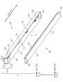
図1は、本実施の形態における照明器具1を示す斜視図である。
図2は、本実施の形態における照明器具1の分解斜視図である。
図1及び図2に示すように、照明器具1は、長尺に形成された光源ユニット100と、被取付部500に設置され、光源ユニット100が取り付けられる器具本体200とを備えている。
FIG. 1 is a perspective view showing a
FIG. 2 is an exploded perspective view of
As shown in FIGS. 1 and 2, the
<光源ユニット100の説明>
図3は、本実施の形態における光源ユニット100の斜視図であり、(a)は上方から見た斜視図、(b)は下方から見た斜視図である。
図4は、本実施の形態における光源ユニット100の分解斜視図である。
図3及び図4に示すように、光源ユニット100は、複数のLED111と複数のLED111が実装されている基板112とからなる発光体110と、発光体110が取り付けられるフレーム部120と、発光体110を覆うようにフレーム部120に取り付くカバー130とを備える。カバー130は、発光体110から照射される光を拡散制御する。また、光源ユニット100は、カバー130の端部を覆う光源蓋140と、器具本体200に固定されるための連結金具150と、発光体110を点灯させる点灯装置160とを備える。
<Description of the
3A and 3B are perspective views of the
FIG. 4 is an exploded perspective view of
As shown in FIGS. 3 and 4, the
発光体110は複数のLED111と複数のLED111を実装する基板112を有しており、照明器具1の長手方向と略同等となるよう長尺に形成されている。また、複数のLED111は基板112の長尺方向へ並ぶよう配設されている。
なお、基板112は、リジットタイプでもフレキシブルタイプでもよい。また、基板112に実装される発光素子は、LED111に限らず、LED以外の発光素子、具体的には、有機ELあるいはレーザといった発光素子を用いてもよい。
The light-emitting
The
フレーム部120は、光源が取り付けられた板状を有し、長尺状に形成されている。フレーム部120は、発光体110が取り付けられる略矩形状をしたフレーム正面部121と、フレーム正面部121の長手方向の両側辺から垂直に突出したフレーム側面部122とを備える。
The
カバー130は、フレーム部120同様に長尺状に形成されている。カバー130は、フレーム部120のフレーム側面部122に係り合いをするカバー爪部131を備える。また、カバー130は、カバー爪部131のフレーム正面部121の側の端部よりフレーム正面部121の内側へ形成された反射部132と、カバー爪部131のフレーム正面部121の側の端部よりフレーム正面部121の外側へ形成された水平部133と、水平部133の端部から発光体110を覆うように略円弧形状をした拡散部134とを備える。
なお、カバー130はアクリル、ポリカーボネートといった樹脂部材により形成されている。
The
The
光源蓋140は、カバー130の水平部133及び拡散部134と、フレーム部120のフレーム正面部121とから構成される端面開口に嵌まり込み、その端面開口を塞いでいる。
なお、光源蓋140もポリカーボネートといった樹脂部材から形成されている。
The
The
図3に示すように、連結金具150は、略L字形状をしており、フレーム部120に固定される連結金具固定部151と、図2の器具本体200に配設されたバネ部230と係り合いする係合開口部153とが形成された連結部152を有している。
連結金具150は、フレーム部120から取付側、すなわち取付方向に立ち上がり、孔である係合開口部153が形成された立上げ部の一例である。また、後述する器具本体200が有するバネ部230は、孔である係合開口部153に挿入され、フレーム部120を取付方向に引き付ける。
As shown in FIG. 3, the connecting fitting 150 has a substantially L shape, and includes a connecting fitting fixing
The
また、図3に示すように、点灯装置160は、フレーム正面部121の発光体110が取り付けられた面の反対側の面に固定される。光源を点灯させる点灯装置160は、フレーム部120の長手方向の略中央部に設置される。
点灯装置160は、図2に示す器具本体200に設置された端子台250を介して商用電源からの電力を発光体110に供給し、発光体110を点灯させる。点灯装置160は、図示しない電源回路が内蔵され長尺形状をした電源本体部161と、図6に示す端子台250の端子台接続部252と接続する電源接続部162とを備えている。電源接続部162は、電源電線162aと、電源電線162aの先端に設けられ、図6の端子台接続部252の端子台コネクタ252bと接続する電源コネクタ162bとを備えている。
Further, as shown in FIG. 3, the
The
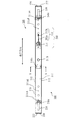
<器具本体200の説明>
図5は、本実施の形態における器具本体200の分解斜視図である。
図6は、本実施の形態における器具本体200の平面図、すなわち図2におけるA矢視図である。
図7は、本実施の形態における台部240の斜視図である。
図8は、本実施の形態における器具本体200の断面図、すなわち図6におけるB−B断面図である。
<Explanation of the
FIG. 5 is an exploded perspective view of
FIG. 6 is a plan view of the instrument
FIG. 7 is a perspective view of
FIG. 8 is a cross-sectional view of the instrument
器具本体200は、長尺に形成される。器具本体200は、光源ユニット100の一部が挿入される凹部210と、凹部210の長手端部を塞ぐよう取り付けられる器具蓋部220とを備える。また、器具本体200は、凹部210に配置され光源ユニット100を固定するバネ部230と、バネ部230を凹部210に固定する台部240と、端子台250とを有している。
The
凹部210は、底面部211と側面部212とを有する。また、凹部210は、側面部212の先端部を開口縁とした開口部213が形成され、フレーム部120により開口部213が塞がれた状態で光源ユニット100を取り付ける。以下に凹部210について詳しく説明する。
凹部210は、図5および図8に示すように、短手方向断面において一辺が開口した開口部213となっている略四角形状である。凹部210は、被取付部500に当接し固定される底面部211と、底面部211の短手方向の各両端より被取付部500と反対方向に対になるように突設した側面部212とを備える。側面部212は、長手方向へ連続して形成されている。
また、図5および図6に示すように、底面部211は、器具本体200を被取付部500に固定するための一対の固定孔211aAと一対の固定孔211aBとを有する。また、底面部211は、器具本体200の外部から電源電線を引き込むための電源孔211bを有している。一対の固定孔211aAは、器具本体200を被取付部500に取り付けるための取り付け用の穴であり、一方の固定孔211aAはダルマ穴である。一対の固定孔211aAは、例えば、900mmの間隔を有して形成される。一対の固定孔211aBは、器具本体200を被取付部500に取り付けるための取り付け用の穴であり、例えば、720mmの間隔を有して形成される。
The
As shown in FIGS. 5 and 8, the
Further, as shown in FIGS. 5 and 6, the
器具蓋部220は、図5に示すように、凹部210の長手端面に配設される器具蓋本体部221と、凹部210の開口部213の一部を覆うように配設される光源受部222とを有している。
また、器具蓋本体部221には複数の器具本体200を長手方向に連結させたときに、電線などを挿通させるための連結孔221aが形成されている。連結孔221aはノックダウン式などにより形成されており、ペンチなどでねじることで、容易に取外しすることができる。
As shown in FIG. 5, the
Further, the
バネ部230は、連結金具150の係合開口部153に挿入され係り合いする円弧状のバネ円弧部231と、台部240に固定されるバネ固定部232とを有している。バネ部230は、台部240の板部243に取り付けられ、開口部213から底面部211に向かう取付方向に弾性力を有した板バネである。すなわち、バネ部230は、上下方向に弾性力を有している。
The
台部240は、図8に示すように、底面部211に設置される。台部240は、短手方向の両端部2431を有している。両端部2431は、板部243の対になる一対の側辺の例である。台部240は、底面部211と対向した板部243と、両端部2431から底面部211まで延びた一対の側部242と、両端部2431の少なくとも一端部から側面部212に向かって突出した電線保持部244とを有する。電線保持部244は、凹部210の内部に配線された電線50を保持している。本実施の形態では、電線保持部244は両端部2431の各々から突出して形成されている。
なお、台部240はバネ取付台ともいう。また、台部240の板部243は台部受部ともいう。以下に台部240について詳しく説明する。
The
The
台部240は、図7に示すように、略ハット型形状をしている。台部240は、底面部211に固定される台部脚部241と、台部脚部241から被取付部500と反対方向に立ち上った側部242と、側部242の端部より底面部211と略平行に形成された板部243とを備える。また、台部240は、板部243の側方に台部脚部241と対面するように設けられた電線保持部244を有している。
また、板部243は、バネ部230のバネ固定部232が挿し込まれるスリット部243aと、バネ固定部232がスリット部243aに挿し込まれた後にネジなどにより固定するバネ固定孔243bとが形成されている。
As shown in FIG. 7, the
In addition, the
台部240は、図8に示すように、台部脚部241、側部242、電線保持部244、および凹部210の側面部212で囲まれたケーブル保持空間900に電線50を保持するものである。電線50は、開口部213の側から電線保持部244を押し込みケーブル保持空間900に挿入される。ケーブル保持空間900は電線保持空間の例である。つまり、台部240は、底面部211と対向した板部243と、板部243の対になる一対の側辺(即ち、両端部2431)の各々から底面部211まで延びると共に側方に電線保持空間(即ち、ケーブル保持空間900)を有する側部242とを有し、底面部211に設置されている。
As shown in FIG. 8, the
電線保持部244は、底面部211に向かって傾斜している。また、電線保持部244は、開口部213から底面部211に向かう取付方向に弾性力を有している。すなわち、電線保持部244は、板部243の側辺から台部脚部241の側へ傾斜した形状であり弾性を有している。よって、電線50がケーブル保持空間900に挿入される場合は、電線保持部244の傾斜がガイドとなり挿入されやすい。また、電線50がケーブル保持空間900に挿入された後は、電線保持部244は弾性変形しにくく、電線50が引っ掛かり、外れ難い形状になっている。
また、台部240は、台部脚部241および側部242をそれぞれ対になるように形成されている。台部240は、この対になる台部脚部241および側部242により底面部211に固定されていることで、ケーブル保持空間900に電線50を挿入するときおよび挿入された状態において、電線50に台部240が押されて底面部211からはずれてしまうことを防いでいる。
The
Further, the
図5及び図6に示すように、台部240は、少なくとも第1の台部240aと、第2の台部240cと、第3の台部240bとを備える。第1の台部240aと第2の台部240cとの各々は、底面部211の長手方向の両側の端部の各端部と底面部211の長手方向の中央部との間に設けられる。また、第3の台部240bは、底面部211の長手方向の中央部に設けられ、第3の台部240bの板部243と点灯装置160とが接する。
すなわち、台部240は、器具本体200の長手方向において少なくとも3ヶ所に配設されている。この3ヶ所に配設された台部240のうち、各端部側に配置された2つ(第1の台部240aと第2の台部240c)にはバネ部230が取り付けられている。略中央に配置された台部240(第3の台部240b)にはバネ部230は取り付けられておらず、光源ユニット100の点灯装置160の一部と当接する。このように、台部240が点灯装置160の一部と当接することにより、光源ユニット100が凹部210の内側へ入り込み過ぎることを防いでいる。つまり、略中央に配置された台部240は、光源ユニット100が長手方向両端部のバネ部230により凹部210へ引っ張られ、光源ユニット100中央部が器具本体200の側に反るように変形するのを抑制するソリ防止金具である。したがって、ソリ防止金具である第3の台部240bには、バネ部230が取り付けるためのスリット部243aとバネ固定孔243bとは形成されていない。なお、第3の台部240bが第1の台部240aや第2の台部240cと同様の形状であってもよい。
As shown in FIGS. 5 and 6, the
That is, the
端子台250は、外部から引き込まれた電源電線が接続され、点灯装置160に電力を供給するものである。端子台250は、凹部210の底面部211に固定されており、電源孔211bから引き込まれた電源電線と接続し、商用電源から供給される電力を光源ユニット100に供給する。
端子台250は図5に示すように、矩形箱状に形成された端子台本体部251と、点灯装置160に電気的に接続する為の端子台接続部252とを備えている。端子台接続部252は、端子台電線252aと、端子台電線252aの先端に設けられた端子台コネクタ252bとを有している。また、端子台本体部251は、外部から引き込まれた電源ケーブルが接続される入力部251aと、入力された電力を隣接する照明器具などの外部へ出される電源ケーブルが接続されている出力部251bとを有している。
The
As shown in FIG. 5, the
<照明器具1の被取付部500への取り付け方法について>
次に、照明器具1を被取付部500に取り付ける方法を説明する。
(1)はじめに、器具本体200を被取付部500に固定する。器具本体200は、凹部210の底面部211が被取付部500の側になるよう配置され、固定孔211aを介して固定具により固定される。このとき、電源孔211bより外部から電源電線を引き込み端子台250の入力部251aに接続させる。
(2)次に、器具本体200に配設されたバネ部230のバネ円弧部231の先端を、光源ユニット100の連結金具150の係合開口部153に引っ掛ける。このとき、電源接続部162と端子台接続部252とが接続される。
(3)次に、光源ユニット100の一部が器具本体200の凹部210内側に挿入されるように、光源ユニット100を器具本体200の側へ押し込む。
このとき、バネ円弧部231が係合開口部153の縁部を摺動してバネ部230が光源ユニット100を器具本体200の側へ引き込むとともに、光源ユニット100が器具蓋部220の光源受部222に当接して光源ユニット100が器具本体200に固定される。また、連結金具150の連結部152の先端が台部240の板部243と接触し、光源ユニット100が凹部210の内側へ入り込み過ぎることを防いでいる。つまり、長手方向両端部の側の2つの台部240は、光源ユニット100の凹部210の内側における位置決め機能を有している。また、略中央に配置された台部240と、光源ユニット100の点灯装置の電源本体部161とが接触し、光源ユニット100の反りを抑制している。
なお、本実施の形態では一例として天井を被取付部500として説明しているが、被取付部500は天井に限るものではなく、レースウェイといった構造体であってもよい。
<How to attach the
Next, a method of attaching the
(1) First, the
(2) Next, the tip of the spring
(3) Next, the
At this time, the
Although the ceiling is described as the mounted
<連結された器具本体の配線について>
図9は、本実施の形態における照明器具1の配線方法に関する参考図である。
照明器具1を連結する際の配線方法について、図9を用いて説明する。
図9は、器具本体200Aの両側に隣接して器具本体200B,200Cが各々取り付けられている状態を示している。器具本体200A,200B,200Cは、上述した器具本体200と同一である。
器具本体200Aと器具本体200Bとは、器具蓋部220Aと器具蓋部220Bとが当接するように配設されている。また、器具本体200Aと器具本体200Cとは、器具蓋部220Aと器具蓋部220Cとが当接するように配設されている。各器具蓋部220A,220B,220Cは、それぞれの連結孔221aが取り外された状態であり、互いに電線50が挿通可能な状態である。
<About the wiring of the connected instrument body>
FIG. 9 is a reference diagram related to a wiring method of
A wiring method for connecting the
FIG. 9 shows a state in which
The instrument
以下の説明において、器具本体200が有する構成部に添え字A,B,Cを付した場合は、器具本体200A,200B,200Cの有する構成部を意味するものとする。
器具本体200Aは、連結孔221aA,221aBを介して器具本体200Bから引き込まれた電線50である電源ケーブル501が、器具本体200Aの端子台250Aの入力部251aAに接続されている。また、端子台250Aの出力部251bAに接続された電線50である電源ケーブル502は連結孔221aA,221aCを介して器具本体200Aから器具本体200Cに送り配線される。このとき、図8に示すように、電源ケーブル501,502はケーブル保持空間900に挿入される。電源ケーブル501,502は、電線保持部244によってケーブル保持空間900の内側に保持されることで、開口部213の側へ垂れ下ることが抑制される。このように、本実施の形態に係る照明器具1によれば、光源ユニット100を器具本体200に取り付ける際に、光源ユニット100と器具本体200の間に電源ケーブル501,502が挟まれることを防ぐことができる。
In the following description, when suffixes A, B, and C are attached to the constituent parts of the
In the
***他の構成***
図10は、本実施の形態における台部240の変形例である台部270を示す図である。
照明器具1において、台部240に替えて図10に示す台部270を用いてもよい。この台部270は、板部273が側部272より長く形成されている。電線保持部274は、板部273において側部272より長く形成された部分に設けられる。よって、電線保持部274が弾性変形しやすくなり、より電線50をケーブル保持空間900に押し込み易くなる。
***Other configurations***
FIG. 10 is a diagram showing a
In the
図11は、本実施の形態における台部240の変形例である台部240xを示す図である。
照明器具1において、台部240に替えて図11に示す台部240xを用いてもよい。この台部240xは、板部243xの側辺部のうち両端部2431xと直交する側辺部2432xに、板部243xと側部242xにより囲まれた空間を塞ぐように形成されたカバー部299が形成されている。
このカバー部299により、電線50を配線する際に、電線50がケーブル保持空間900以外の空間に配置されることを抑制することができる。また、板部243xと側部242xにより囲まれた空間およびその周辺にネジなどの突出物が配置されていた際には、この突出物と電線50との干渉を防ぎ、電線50の損傷を防止することができる。
FIG. 11 is a diagram showing a
In the
The
なお、器具本体200はトラフ型の照明器具に関して説明を行ったが、逆富士形状をした器具本体でもよく、天井に埋め込まれる埋込型形状をした照明器具でもよい。
It should be noted that although the fixture
***本実施の形態の効果の説明***
本実施の形態に係る照明器具によれば、器具本体の凹部に電線保持部を有した台部を備えていることで、凹部の内側に配線された電源ケーブルの垂れ下りを抑制することができる。よって、器具本体に光源ユニットの取り付けをおこなったときに、電源ケーブルが光源ユニットと器具本体との間にはさまれるのを防ぐことができる。
***Explanation of the effect of this embodiment***
According to the lighting fixture of the present embodiment, since the recess of the fixture main body is provided with the pedestal having the wire holding portion, it is possible to prevent the power cable wired inside the recess from hanging down. .. Therefore, when the light source unit is attached to the instrument body, the power cable can be prevented from being caught between the light source unit and the instrument body.
本実施の形態に係る照明器具の器具本体は、被取付部に取付具により固定される底面部である第一の底面と、第一の底面と光源ユニットとの間に位置し電源ケーブルを保持する電線保持部である第二の底面とを有している。このような構成により、電源ケーブルを保持するケーブル保持空間を確保するとともに、電源ケーブルの垂れ下がりを抑制し電源ケーブルが挟まれるのを防ぐことができる。
また、電線保持部である第二の底面は、器具本体の長手方向において、断続的に設けられているので、ケーブル保持空間に電源ケーブルを挿入し易い。
また、電線保持部である第二の底面は、弾性機能を有すると共に傾斜しているので、ケーブル保持空間に電源ケーブルを挿入し易く、かつ、ケーブル保持空間から電源ケーブルが外れ難い。
The fixture body of the lighting fixture according to the present embodiment is located between the first bottom face, which is the bottom face part fixed to the attached part by the fixture, and holds the power cable between the first bottom face and the light source unit. And a second bottom surface which is an electric wire holding portion. With such a configuration, it is possible to secure a cable holding space for holding the power cable, suppress the sagging of the power cable, and prevent the power cable from being pinched.
Moreover, since the second bottom surface, which is the wire holding portion, is provided intermittently in the longitudinal direction of the instrument body, it is easy to insert the power cable into the cable holding space.
Further, since the second bottom surface, which is the wire holding portion, has an elastic function and is inclined, the power cable can be easily inserted into the cable holding space, and the power cable is unlikely to come off from the cable holding space.
また、本実施の形態に係る照明器具によれば、電源ケーブルは開口部の側から電線保持部に押し込みケーブル保持空間に挿入することができ、長手方向に挿し通すより容易に取り付けることができる。また、電線保持部は斜めに形成されていることで、電源ケーブルの挿入をガイドし、挿入し易い。また、電線保持部は弾性を有していることで電源ケーブルを挿入し易く、挿入後は外れ難い。 Further, according to the lighting equipment of the present embodiment, the power cable can be pushed into the wire holding portion from the opening side and inserted into the cable holding space, and can be attached more easily than by inserting it in the longitudinal direction. In addition, since the wire holding portion is formed obliquely, it is easy to guide and insert the power cable. Further, since the wire holding portion has elasticity, the power cable can be easily inserted, and it is difficult to remove it after the insertion.
また、本実施の形態に係る照明器具によれば、台部は電線ケーブルに押されて底面部からはずれてしまうことを防ぐように、対になる側部の2ヶ所で底面部に固定されている。よって、台部ははずれることなく電源ケーブルを保持することができる。 In addition, according to the lighting equipment of the present embodiment, the pedestal is fixed to the bottom surface portion at two positions on the pair of side portions so as to prevent the pedestal portion from being pushed by the electric wire cable and coming off the bottom surface portion. There is. Therefore, the power cable can be held without the stand portion being detached.
また、本実施の形態に係る照明器具によれば、台部に電線保持部が一体に形成されている。よって、部品点数を抑えることができる。 Further, according to the lighting fixture of the present embodiment, the wire holding portion is integrally formed on the base portion. Therefore, the number of parts can be suppressed.
なお、本実施の形態では、隣接する照明器具同士を電気的に接続させる線を電線あるいは電源ケーブルとして説明したが、ケーブル保持空間に配置される電線は、外部に設けられた商用電源から引き込まれる電源でもよく、それ以外の電線であってもよい。 In the present embodiment, the wire that electrically connects the adjacent lighting fixtures has been described as the electric wire or the power cable, but the electric wire arranged in the cable holding space is drawn from the commercial power supply provided outside. It may be a power source or another electric wire.
実施の形態2.
本実施の形態では、主に、実施の形態1と異なる点について説明する。
本実施の形態では、実施の形態1で説明した台部240と異なる台部260について説明する。なお、実施の形態1と同様の構成部については同一の符号を付し、その説明を省略する場合がある。
Embodiment 2.
In the present embodiment, points different from the first embodiment will be mainly described.
In this embodiment, a
図12は、本実施の形態における台部260の斜視図である。
図13は、本実施の形態における器具本体200の断面図である。
本実施の形態では、台部260は、底面部211と一対の側部262と板部263とにより囲まれた空間であるケーブル保持空間901に凹部210の内部に配線された電線50を保持する。
FIG. 12 is a perspective view of
FIG. 13 is a sectional view of
In the present embodiment, the
台部260は、図12及び図13に示すように、器具本体200の底面部211にネジなどにより固定される一対の台部脚部261を備える。また、台部260は、対になる台部脚部261のそれぞれ外側端部より開口部213の側へ形成された側部262と、対になる側部262の端部を連結させるものであり底面部211と略平行に形成された板部263とを有している。対になる側部262の間の距離は、凹部210において対になる側面部212の距離と同等の距離となるように形成されている。
As shown in FIGS. 12 and 13, the
また、板部263は、バネ部230のバネ固定部232が挿し込まれるスリット部263aと、バネ固定部232がスリット部263aに挿し込まれた後にネジなどにより固定するためのバネ固定孔263bとが形成されている。
この板部263における側部262が形成された一対の側辺262aと異なる一対の側辺262bに、ケーブルガイド部263cが形成される。ケーブルガイド部263cは、電線50が挿通された際に、電線50が板部263の一対の側辺262bの端面と干渉し損傷するのを防止すると共に、電線50の誘導機構となる。ケーブルガイド部263cは、板部263の一対の側辺262bの各々において、板部263の端部を被取付部500の側に湾曲させた曲面部を形成すると共に、被取付部500あるいは底面部211の側に傾斜させて形成される。
Further, the
A
台部260は、凹部210に配設された状態において、底面部211と、一対の側部262と、板部263とに囲まれたケーブル保持空間901を形成する。
板部263は、短手方向において底面部211と略同等の長さに形成されており、ケーブル保持空間901は短手方向に大きく、広く形成することができる。また、電線50を引掛けるものでなく挿通させる形状であるため、引掛ける形状に比べ、より強固に電線50を保持することができる。
また、板部263は、実施の形態1と同様に、器具本体200の凹部210の長手方向において少なくとも3ヶ所に部分的設けられている。よって、電線50を挿通する長さは短く挿通作業を容易にすることができる。
The
The
Further, the
なお、実施の形態1で示した台部240と、実施の形態2で示した台部260の両方を1つの器具本体200に配設してもよい。例えば、長手方向のおける端部側に台部260を配設し、略中央に台部240を配設するようなものでもよい。
It should be noted that both the base 240 shown in the first embodiment and the base 260 shown in the second embodiment may be provided in one
なお、実施の形態1で示した台部240と、実施の形態2で示した台部260それぞれに、スリット部およびバネ固定孔が形成されているが、器具本体200に配設される台部のうちバネ部230が配設されない台部240、260はスリット部およびバネ固定孔が形成されていないものを用いてもよい。
It should be noted that although the slit portion and the spring fixing hole are formed in each of the
以上、本発明の実施の形態1,2について説明したが、これらの実施の形態のうち、2つ以上を組み合わせて実施しても構わない。あるいは、これらの実施の形態のうち、1つを部分的に実施しても構わない。あるいは、これらの実施の形態のうち、2つ以上を部分的に組み合わせて実施しても構わない。その他、これらの実施の形態を、全体としてあるいは部分的に、どのように組み合わせて実施しても構わない。
なお、上記の実施の形態は、本質的に好ましい例示であって、本発明、その適用物及び用途の範囲を制限することを意図するものではなく、必要に応じて種々の変更が可能である。
Although the first and second embodiments of the present invention have been described above, two or more of these embodiments may be combined and implemented. Alternatively, one of these embodiments may be partially implemented. Alternatively, two or more of these embodiments may be partially combined for implementation. In addition, these embodiments may be implemented in whole or in part in any combination.
Note that the above-described embodiments are essentially preferable examples, and are not intended to limit the scope of the present invention, its applications, and uses, and various modifications can be made as necessary. ..
1 照明器具、100 光源ユニット、110 発光体、111 LED、112 基板、120 フレーム部、121 フレーム正面部、122 フレーム側面部、130 カバー、131 カバー爪部、132 反射部、133 水平部、134 拡散部、140 光源蓋、150 連結金具、151 連結金具固定部、152 連結部、153 係合開口部、160 点灯装置、161 電源本体部、162 電源接続部、162a 電源電線、162b 電源コネクタ、200,200A,200B,200C 器具本体、210 凹部、211 底面部、211aA,211aB 固定孔、211b 電源孔、212 側面部、213 開口部、220,220A,220B,220C 器具蓋部、221 器具蓋本体部、221a,221aA 連結孔、222 光源受部、230 バネ部、231 バネ円弧部、232 バネ固定部、240,240x,260,270 台部、240a 第1の台部、240b 第3の台部、240c 第2の台部、241,261,271 台部脚部、242,242x,262,272 側部、243,243x,263,273 板部、2431,2431x 両端部、2432x 側辺部、243a,263a,273a スリット部、243b,263b,273b バネ固定孔、244,264,274 電線保持部、250,250A 端子台、251 端子台本体部、251a,251aA 入力部、251b,251bA 出力部、252 端子台接続部、252a 端子台電線、252b 端子台コネクタ、263c ケーブルガイド部、262a,262b 一対の側辺、299 カバー部、50 電線、501,502 電源ケーブル、500 被取付部、900,901 ケーブル保持空間。 1 lighting equipment, 100 light source unit, 110 light emitter, 111 LED, 112 substrate, 120 frame part, 121 frame front part, 122 frame side part, 130 cover, 131 cover claw part, 132 reflective part, 133 horizontal part, 134 diffusion Part, 140 light source lid, 150 connecting metal fitting, 151 connecting metal fitting fixing part, 152 connecting part, 153 engaging opening part, 160 lighting device, 161 power supply main body part, 162 power supply connecting part, 162a power supply wire, 162b power supply connector, 200, 200A, 200B, 200C appliance body, 210 recessed portion, 211 bottom surface portion, 211aA, 211aB fixing hole, 211b power supply hole, 212 side surface portion, 213 opening portion, 220, 220A, 220B, 220C instrument lid portion, 221 instrument lid body portion, 221a, 221aA connection hole, 222 light source receiving portion, 230 spring portion, 231 spring arc portion, 232 spring fixing portion, 240, 240x, 260, 270 stand portion, 240a first stand portion, 240b third stand portion, 240c 2nd base part, 241, 261, 271 base part leg part, 242, 242x, 262, 272 side part, 243, 243x, 263, 273 plate part, 2431, 2431x both ends part, 2432x side part 243a, 263a , 273a slit part, 243b, 263b, 273b spring fixing hole, 244, 264, 274 electric wire holding part, 250, 250A terminal block, 251 terminal block body part, 251a, 251aA input part, 251b, 251bA output part, 252 terminal block Connection part, 252a terminal block wire, 252b terminal block connector, 263c cable guide part, 262a, 262b pair of sides, 299 cover part, 50 wire, 501,502 power cable, 500 attached part, 900,901 cable holding space ..
Claims (7)
底面部と側面部とを有した凹部であって、前記側面部の先端部を開口縁とした開口部が形成され、前記フレーム部により前記開口部が塞がれた状態で前記光源ユニットを取り付けた凹部と、
前記底面部と対向した板部と、前記板部の対になる一対の側辺の各々から前記底面部まで延びると共に側方に電線保持空間を有する側部とを有し、前記底面部に設置された台部と
を備え、
前記台部は、
前記光源ユニットと当接する照明器具。 A light source unit having a plate-shaped frame portion to which a light source is attached,
A recess having a bottom surface portion and a side surface portion, the opening portion having a front end portion of the side surface portion as an opening edge is formed, and the light source unit is attached with the frame portion closing the opening portion. Recessed
Installed on the bottom surface portion, having a plate portion facing the bottom surface portion, and a side portion extending from each of a pair of side edges of the plate portion to the bottom surface portion and having a wire holding space laterally. and a dies part,
The pedestal is
A lighting fixture that contacts the light source unit .
底面部と側面部とを有した凹部であって、前記側面部の先端部を開口縁とした開口部が形成され、前記フレーム部により前記開口部が塞がれた状態で前記光源ユニットを取り付けた凹部と、
前記底面部と対向した板部と、前記板部の対になる一対の側辺の各々から前記底面部まで延びると共に側方に電線保持空間を有する側部とを有し、前記底面部に設置された台部と
を備え、
前記台部は、
前記一対の側辺の少なくとも一方の側辺から前記側面部に向かって突出しており、前記電線保持空間に配線された電線を保持した電線保持部を有する照明器具。 A light source unit having a plate-shaped frame portion to which a light source is attached,
A recess having a bottom surface portion and a side surface portion, the opening portion having a front end portion of the side surface portion as an opening edge is formed, and the light source unit is attached with the frame portion closing the opening portion. Recessed
Installed on the bottom surface portion, having a plate portion facing the bottom surface portion, and a side portion extending from each of a pair of side edges of the plate portion to the bottom surface portion and having a wire holding space laterally. The pedestal
Equipped with
The pedestal is
A lighting fixture having an electric wire holding portion that holds an electric wire wired in the electric wire holding space, projecting from at least one of the pair of side edges toward the side surface portion .
前記底面部に向かって傾斜している請求項2に記載の照明器具。 The electric wire holding portion,
The lighting fixture according to claim 2 , wherein the lighting fixture is inclined toward the bottom surface portion.
前記開口部から前記底面部に向かう取付方向に弾性力を有している請求項2または請求項3に記載の照明器具。 The electric wire holding portion,
The lighting fixture according to claim 2 or 3 , which has an elastic force in a mounting direction from the opening to the bottom surface.
前記底面部と、前記側部と、前記板部とにより囲まれた空間に前記凹部の内部に配線された電線を保持した請求項1から請求項4のいずれか1項に記載の照明器具。 The pedestal is
The lighting fixture according to any one of claims 1 to 4 , wherein an electric wire wired inside the recess is held in a space surrounded by the bottom surface portion, the side portion, and the plate portion.
底面部と側面部とを有した凹部であって、前記側面部の先端部を開口縁とした開口部が形成され、前記フレーム部により前記開口部が塞がれた状態で前記光源ユニットを取り付けた凹部と、
前記底面部と対向した板部と、前記板部の対になる一対の側辺の各々から前記底面部まで延びると共に側方に電線保持空間を有する側部とを有し、前記底面部に設置された台部と、
前記板部に取り付けられ、前記開口部から前記底面部に向かう取付方向に弾性力を有した板バネと
を備え、
前記光源ユニットは、
前記フレーム部から取付方向に立ち上がった立上げ部であって孔が形成された立上げ部を備え、
前記板バネは、
前記孔に挿入されており、前記フレーム部を取付方向に引き付けている照明器具。 A light source unit having a plate-shaped frame portion to which a light source is attached,
A recess having a bottom surface portion and a side surface portion, the opening portion having a front end portion of the side surface portion as an opening edge is formed, and the light source unit is attached with the frame portion closing the opening portion. Recessed
Installed on the bottom surface portion, having a plate portion facing the bottom surface portion, and a side portion extending from each of a pair of side edges of the plate portion to the bottom surface portion and having a wire holding space laterally. The pedestal ,
Attached to said plate portion includes a <br/> a leaf spring having an elastic force to the mounting direction toward the bottom portion from the opening,
The light source unit,
A stand-up part that stands up from the frame part in the mounting direction and has a hole formed therein,
The leaf spring is
A lighting fixture that is inserted into the hole and that pulls the frame portion in the mounting direction.
底面部と側面部とを有した凹部であって、前記側面部の先端部を開口縁とした開口部が形成され、前記フレーム部により前記開口部が塞がれた状態で前記光源ユニットを取り付けた凹部と、
前記底面部と対向した板部と、前記板部の対になる一対の側辺の各々から前記底面部まで延びると共に側方に電線保持空間を有する側部とを有し、前記底面部に設置された台部と
を備え、
前記底面部と前記フレーム部との各々は、
長手方向に延びた形状であり、
前記光源ユニットは、
前記光源を点灯させる点灯装置が前記フレーム部の長手方向の中央部に設置され、
前記台部は、
少なくとも第1の台部と、第2の台部と、第3の台部とを備え、
前記第1の台部と前記第2の台部との各々は、
前記底面部の長手方向の両側の端部の各端部と前記底面部の長手方向の中央部との間に設けられ、
前記第3の台部は、
前記底面部の長手方向の中央部に設けられ、前記板部と前記点灯装置とが接している照明器具。 A light source unit having a plate-shaped frame portion to which a light source is attached,
A recess having a bottom surface portion and a side surface portion, the opening portion having a front end portion of the side surface portion as an opening edge is formed, and the light source unit is attached with the frame portion closing the opening portion. Recessed
Installed on the bottom surface portion, having a plate portion facing the bottom surface portion, and a side portion extending from each of a pair of side edges of the plate portion to the bottom surface portion and having a wire holding space laterally. The pedestal
Equipped with
Each of the bottom portion and the frame portion,
It has a shape that extends in the longitudinal direction,
The light source unit,
A lighting device for lighting the light source is installed in a central part in the longitudinal direction of the frame part,
The pedestal is
At least a first table portion, a second table portion, and a third table portion,
Each of the first platform and the second platform is
Provided between each end of both end portions in the longitudinal direction of the bottom surface portion and the central portion in the longitudinal direction of the bottom surface portion,
The third platform is
A luminaire which is provided at a central portion in the longitudinal direction of the bottom surface portion and in which the plate portion and the lighting device are in contact with each other.
Priority Applications (1)
| Application Number | Priority Date | Filing Date | Title |
|---|---|---|---|
| JP2016011816A JP6726971B2 (en) | 2016-01-25 | 2016-01-25 | lighting equipment |
Applications Claiming Priority (1)
| Application Number | Priority Date | Filing Date | Title |
|---|---|---|---|
| JP2016011816A JP6726971B2 (en) | 2016-01-25 | 2016-01-25 | lighting equipment |
Publications (3)
| Publication Number | Publication Date |
|---|---|
| JP2017134916A JP2017134916A (en) | 2017-08-03 |
| JP2017134916A5 JP2017134916A5 (en) | 2018-12-13 |
| JP6726971B2 true JP6726971B2 (en) | 2020-07-22 |
Family
ID=59504470
Family Applications (1)
| Application Number | Title | Priority Date | Filing Date |
|---|---|---|---|
| JP2016011816A Active JP6726971B2 (en) | 2016-01-25 | 2016-01-25 | lighting equipment |
Country Status (1)
| Country | Link |
|---|---|
| JP (1) | JP6726971B2 (en) |
Families Citing this family (1)
| Publication number | Priority date | Publication date | Assignee | Title |
|---|---|---|---|---|
| JP7378289B2 (en) | 2019-12-18 | 2023-11-13 | 三菱電機株式会社 | Lighting equipment and lighting equipment |
-
2016
- 2016-01-25 JP JP2016011816A patent/JP6726971B2/en active Active
Also Published As
| Publication number | Publication date |
|---|---|
| JP2017134916A (en) | 2017-08-03 |
Similar Documents
| Publication | Publication Date | Title |
|---|---|---|
| JP2014220034A (en) | Lighting apparatus, light source component, and mounting component | |
| JP6106709B2 (en) | lighting equipment | |
| JP5519445B2 (en) | lighting equipment | |
| JP6665912B2 (en) | lighting equipment | |
| JP6726971B2 (en) | lighting equipment | |
| JP6421976B2 (en) | lighting equipment | |
| JP6223005B2 (en) | lighting equipment | |
| JP2013093270A (en) | Lighting system | |
| JP6731636B2 (en) | lighting equipment | |
| JP6444255B2 (en) | Lighting device | |
| JP2014179211A (en) | Light source unit and lighting fixture using the same | |
| JP2017079204A (en) | Lighting device, arrangement structure of lighting device, and light-emitting unit | |
| JP2020167119A (en) | Luminaire | |
| JP6258601B2 (en) | Embedded electronic devices and mounting springs | |
| JP6967474B2 (en) | Light source unit and lighting equipment | |
| JP7061273B2 (en) | Spring devices and lighting fixtures | |
| JP7021581B2 (en) | lighting equipment | |
| JP7268363B2 (en) | lighting equipment | |
| JP7051501B2 (en) | Light source unit and lighting equipment | |
| JP7085811B2 (en) | Lighting equipment and lighting equipment | |
| JP2016157581A (en) | Light source unit, lighting fixture and luminaire | |
| JP7107705B2 (en) | Light source unit and lighting equipment | |
| JP6640032B2 (en) | Lighting equipment | |
| JP2016122603A (en) | Luminaire and lighting system | |
| JP6717588B2 (en) | Lighting equipment and lighting equipment |
Legal Events
| Date | Code | Title | Description |
|---|---|---|---|
| A521 | Request for written amendment filed |
Free format text: JAPANESE INTERMEDIATE CODE: A523 Effective date: 20181102 |
|
| A621 | Written request for application examination |
Free format text: JAPANESE INTERMEDIATE CODE: A621 Effective date: 20181102 |
|
| A977 | Report on retrieval |
Free format text: JAPANESE INTERMEDIATE CODE: A971007 Effective date: 20190927 |
|
| A131 | Notification of reasons for refusal |
Free format text: JAPANESE INTERMEDIATE CODE: A131 Effective date: 20191029 |
|
| A521 | Request for written amendment filed |
Free format text: JAPANESE INTERMEDIATE CODE: A523 Effective date: 20191128 |
|
| TRDD | Decision of grant or rejection written | ||
| A01 | Written decision to grant a patent or to grant a registration (utility model) |
Free format text: JAPANESE INTERMEDIATE CODE: A01 Effective date: 20200602 |
|
| A61 | First payment of annual fees (during grant procedure) |
Free format text: JAPANESE INTERMEDIATE CODE: A61 Effective date: 20200630 |
|
| R150 | Certificate of patent or registration of utility model |
Ref document number: 6726971 Country of ref document: JP Free format text: JAPANESE INTERMEDIATE CODE: R150 |
|
| R250 | Receipt of annual fees |
Free format text: JAPANESE INTERMEDIATE CODE: R250 |