JP6725035B2 - Management system, transmission system, transmission management method, and program - Google Patents

Management system, transmission system, transmission management method, and program Download PDF

Info

Publication number
JP6725035B2
JP6725035B2 JP2019086538A JP2019086538A JP6725035B2 JP 6725035 B2 JP6725035 B2 JP 6725035B2 JP 2019086538 A JP2019086538 A JP 2019086538A JP 2019086538 A JP2019086538 A JP 2019086538A JP 6725035 B2 JP6725035 B2 JP 6725035B2
Authority
JP
Japan
Prior art keywords
terminal
communication
conference
identification information
information
Prior art date
Legal status (The legal status is an assumption and is not a legal conclusion. Google has not performed a legal analysis and makes no representation as to the accuracy of the status listed.)
Active
Application number
JP2019086538A
Other languages
Japanese (ja)
Other versions
JP2019154056A (en
Inventor
田中 謙次
謙次 田中
浅井 貴浩
貴浩 浅井
Current Assignee (The listed assignees may be inaccurate. Google has not performed a legal analysis and makes no representation or warranty as to the accuracy of the list.)
Ricoh Co Ltd
Original Assignee
Ricoh Co Ltd
Priority date (The priority date is an assumption and is not a legal conclusion. Google has not performed a legal analysis and makes no representation as to the accuracy of the date listed.)
Filing date
Publication date
Application filed by Ricoh Co Ltd filed Critical Ricoh Co Ltd
Priority to JP2019086538A priority Critical patent/JP6725035B2/en
Publication of JP2019154056A publication Critical patent/JP2019154056A/en
Application granted granted Critical
Publication of JP6725035B2 publication Critical patent/JP6725035B2/en
Active legal-status Critical Current
Anticipated expiration legal-status Critical

Links

Images

Landscapes

  • Two-Way Televisions, Distribution Of Moving Picture Or The Like (AREA)
  • Telephonic Communication Services (AREA)

Description

本発明は、管理システム、伝送システム、伝送管理方法、及びプログラムに関する。 The present invention relates to a management system, a transmission system, a transmission management method, and a program.

近年、出張経費及び出張時間を削減する要請に伴い、インターネット等の通信ネットワークを介してテレビ会議を行うテレビ会議システムが普及している。このようなテレビ会議システムでは、複数の端末の間で通話を開始すると、画像データ及び音声データ等の通話データの送受信が行われ、テレビ会議を実現することができる。 2. Description of the Related Art In recent years, a video conference system that conducts a video conference via a communication network such as the Internet has become widespread in response to a request to reduce travel expenses and travel time. In such a video conference system, when a call is started between a plurality of terminals, call data such as image data and audio data is transmitted and received, and a video conference can be realized.

また、近年のブロードバンド環境の充実化により、複数の通話端末間で高画質の画像データや高音質の音声データの送受信が可能となった。これにより、テレビ会議の相手の状況を把握し易くなり、会話による意思疎通の充実度を向上することができるようになった。 Also, due to the enhancement of the broadband environment in recent years, it has become possible to transmit and receive high-quality image data and high-quality sound data between a plurality of call terminals. As a result, it becomes easier to grasp the situation of the other party in the video conference, and it is possible to improve the degree of communication through conversation.

また、ネットワーク上の通信を会議毎に区別する仮想的な会議室を作成する機能を備え、ユーザーが、当該会議室を選択して端末間の通信を開始するテレビ会議システムが知られている。特許文献1には、仮想的な会議室によって通信するときに、会議に参加する端末の数に応じた制御により、会議システムのリソースの消費を抑える会議システムの発明が開示されている。 In addition, there is known a video conference system that has a function of creating a virtual conference room that distinguishes communication on a network for each conference and allows a user to select the conference room and start communication between terminals. Patent Document 1 discloses an invention of a conference system that suppresses resource consumption of the conference system by controlling according to the number of terminals participating in the conference when communicating in a virtual conference room.

しかしながら、ネットワーク上に仮想的な会議室を提供する従来のテレビ会議システムなどの伝送システムでは、会議名などの情報がわからなければ、当該仮想的な会議室を使用して行われる通信に参加することができなかった。 However, in a transmission system such as a conventional video conference system that provides a virtual conference room on a network, if the information such as the conference name is not known, it participates in communication performed using the virtual conference room. I couldn't.

本発明は、上記に鑑みてなされたものであって、会議名などの会議を特定する情報が正確にわからなくても、仮想的な会議室を使用して宛先端末と通信できるようにする管理システム、伝送システム、伝送管理方法、及びプログラムを提供することを目的とする。 The present invention has been made in view of the above, and management for enabling communication with a destination terminal using a virtual conference room even if information for identifying a conference such as a conference name is not accurately known. An object is to provide a system, a transmission system, a transmission management method, and a program.

上述した課題を解決し、目的を達成するために、本発明は、コンテンツデータを送受信する端末の通信を管理する管理システムであって、第1の端末の識別情報と、前記第1の端末の通信の宛先の候補である1以上の第2の端末の識別情報とを関連付けて管理する宛先端末情報管理部と、前記宛先端末情報管理部によって管理される前記第1の端末の識別情報に関連付けられた前記1以上の第2の端末の識別情報と、端末において受け付けた操作によって指定された1以上の端末が参加可能な会議を識別する会議識別情報のうち、前記1以上の第2の端末の何れかに関連付けられている前記会議識別情報とを前記第1の端末へ送信する送信部と、を備える。前記第1の端末から、表示画面に表示された前記1以上の第2の端末の識別情報のうち、選択された第2の端末の識別情報を宛先とした第1の通信の開始要求を受信した場合には、前記選択された第2の端末の識別情報によって識別される端末を含む複数の端末が参加可能な前記コンテンツデータを送信する通信を確立するための接続制御を実行し、前記送信部によって送信された会議識別情報によって識別される会議であって、表示画面において選択された会議に関連付けられた第2の通信の開始要求を受信した場合には、前記選択された会議に関連付けられた前記1以上の第2の端末が参加可能な前記コンテンツデータを送信する通信を確立するための接続制御を実行することを特徴とする。 To solve the above problems and achieve the object, the present invention provides a management system for managing communications terminus you send and receive content data, the identification information of the first terminal, the first and the destination terminal information management unit for managing in association with identification information a second terminal of the communication terminal 1 or more candidates of the destination of the first terminal managed by the destination terminal information management unit and identification information of the one or more second devices associated with identification information, among the conference identification information for identifying the possible participation meeting one or more terminals that are specified by the operation accepted in the terminal, the 1 and a transmission unit that transmits said conference identification information associated with one of the end or the second end to the first terminal. From said first terminal, among the identification information of the one or more second terminal that is displayed on the display screen, start the identification information of the second terminal that is selected in the first communication destined when receiving the request, executing a plurality of terminals connected control for establishing the communication for transmitting the content data can participate including the terminal identified by the identification information of the second terminal said selected However, when the conference identified by the conference identification information transmitted by the transmitting unit is received and the second communication start request associated with the conference selected on the display screen is received, the selection is performed. and executes the connection control for the one or more second devices associated with the conference to establish a communication for transmitting said content data can participate.

本発明によれば、会議名などの会議を特定する情報が正確にわからなくても、仮想的な会議室を使用して宛先端末と通信できる。 According to the present invention, it is possible to communicate with a destination terminal by using a virtual conference room even if the information for identifying the conference such as the conference name is not exactly known.

図1は、本発明の一実施形態に係る伝送システムの概略図である。FIG. 1 is a schematic diagram of a transmission system according to an embodiment of the present invention. 図2は、本実施形態に係る端末の外観図である。FIG. 2 is an external view of the terminal according to the present embodiment. 図3は、本発明の一実施形態に係る端末のハードウェア構成図である。FIG. 3 is a hardware configuration diagram of the terminal according to the embodiment of the present invention. 図4は、本発明の一実施形態に係る管理システム、中継装置、プログラム提供システム、又はメンテナンスシステムのハードウェア構成図である。FIG. 4 is a hardware configuration diagram of the management system, the relay device, the program providing system, or the maintenance system according to the embodiment of the present invention. 図5は、本発明の一実施形態に係る伝送システムを構成する各端末、装置及びシステムの機能ブロック図である。FIG. 5 is a functional block diagram of each terminal, device, and system configuring the transmission system according to the embodiment of the present invention. 図6は、図5の状態管理部53が詳細に示された機能ブロック図である。FIG. 6 is a functional block diagram showing the state management unit 53 of FIG. 5 in detail. 図7は、図5の中継装置選択部56が詳細に示された機能ブロック図である。FIG. 7 is a functional block diagram showing the relay device selection unit 56 of FIG. 5 in detail. 図8は、中継装置管理テーブルを示す概念図である。FIG. 8 is a conceptual diagram showing the relay device management table. 図9は、端末認証管理テーブルを示す概念図である。FIG. 9 is a conceptual diagram showing a terminal authentication management table. 図10は、端末管理テーブルを示す概念図である。FIG. 10 is a conceptual diagram showing a terminal management table. 図11は、宛先リスト管理テーブルを示す概念図である。FIG. 11 is a conceptual diagram showing the destination list management table. 図12は、セッション管理テーブルを示す概念図である。FIG. 12 is a conceptual diagram showing a session management table. 図13は、中継装置選択管理テーブルを示す概念図である。FIG. 13 is a conceptual diagram showing a relay device selection management table. 図14は、入室管理テーブルを示す概念図である。FIG. 14 is a conceptual diagram showing the entry management table. 図15は、会議室管理テーブルを示す概念図である。FIG. 15 is a conceptual diagram showing a conference room management table. 図16は、各中継装置の稼動状態を示す状態情報を管理する処理を示したシーケンス図である。FIG. 16 is a sequence diagram showing a process of managing status information indicating the operating status of each relay device. 図17は、伝送システムにおける画像データ、音声データ、及び各種管理情報の送受信の状態を示した概念図である。FIG. 17 is a conceptual diagram showing a transmission/reception state of image data, audio data, and various management information in the transmission system. 図18は、宛先端末状態一覧情報を含む画像を示す図である。FIG. 18 is a diagram showing an image including destination terminal status list information. 図19は、宛先端末状態一覧情報を含む画像を、端末に表示する処理を示したシーケンス図である。FIG. 19 is a sequence diagram showing a process of displaying an image including the destination terminal status list information on the terminal. 図20は、通信の開始を要求する処理を示したシーケンス図である。FIG. 20 is a sequence diagram showing a process of requesting the start of communication. 図21は、通信の開始の要求を許可する処理を示したシーケンス図である。FIG. 21 is a sequence diagram showing a process of permitting a request to start communication. 図22は、通信の開始の要求を拒否する処理を示したシーケンス図である。FIG. 22 is a sequence diagram showing a process of rejecting a request to start communication. 図23は、通話データの中継を要求する処理を示したシーケンス図である。FIG. 23 is a sequence diagram showing a process of requesting relay of call data. 図24は、通話データ用セッションへの参加を要求する処理を示したシーケンス図である。FIG. 24 is a sequence diagram showing a process of requesting participation in a call data session. 図25は、通話データ用セッションからの退出を要求する処理を示したシーケンス図である。FIG. 25 is a sequence diagram showing a process of requesting exit from a call data session. 図26は、端末の機能一覧を示す機能一覧画像を示す図である。FIG. 26 is a diagram showing a function list image showing a function list of the terminal. 図27は、会議室一覧を示す会議室一覧画像を示す図である。FIG. 27 is a diagram showing a conference room list image showing a conference room list. 図28は、会議室を新規に作成する時に表示する会議室新規作成画像を示す図である。FIG. 28 is a diagram showing a newly created conference room image displayed when a new conference room is created. 図29は、会議室一覧の表示及び会議室の新規作成時の処理を示したシーケンス図である。FIG. 29 is a sequence diagram showing a process of displaying a conference room list and creating a new conference room. 図30は、会議室の詳細情報を示す会議室詳細画像を示す図である。FIG. 30 is a diagram showing a conference room detailed image showing detailed information of the conference room. 図31は、会議室情報を編集する時に表示する会議室編集画像を示す図である。FIG. 31 is a diagram showing a conference room edited image displayed when the conference room information is edited. 図32は、会議室一覧の表示及び会議室の編集時の処理を示したシーケンス図である。FIG. 32 is a sequence diagram showing a process of displaying a conference room list and editing a conference room. 図33は、会議室一覧から、会議室に入室する時の処理を示したシーケンス図である。FIG. 33 is a sequence diagram showing processing when entering a conference room from the conference room list. 図34は、入室判定の結果に応じた処理を示すフローチャートである。FIG. 34 is a flowchart showing the processing according to the result of the entry determination. 図35は、宛先一覧から、ONライン(通話中)の宛先端末を選択して通信を開始する時の処理を示したシーケンス図である。FIG. 35 is a sequence diagram showing a process for selecting a destination terminal on the ON line (during a call) from the destination list and starting communication. 図36は、宛先一覧から、ONライン(通話可能)の宛先端末を選択して会議室に入室する時の処理を示したフローチャートである。FIG. 36 is a flowchart showing a process when selecting an ON-line (callable) destination terminal from the destination list and entering the conference room.

<<実施形態の全体構成>>
以下、図1乃至図36を用いて、本発明の一実施形態について説明する。図1は、本発明の一実施形態に係る伝送システム1の概略図であり、まずは図1を用いて、本実施形態の概略を説明する。
<<Overall Configuration of Embodiment>>
An embodiment of the present invention will be described below with reference to FIGS. 1 to 36. FIG. 1 is a schematic diagram of a transmission system 1 according to an embodiment of the present invention. First, the outline of the present embodiment will be described using FIG.

伝送システムには、管理システムを介して一方の端末から他方の端末に一方向でコンテンツデータを伝送するデータ提供システムや、管理システムを介して複数の端末間で情報や感情等を相互に伝達するコミュニケーションシステムが含まれる。このコミュニケーションシステムは、コミュニケーション管理システム(「管理システム」に相当)を介して複数のコミュニケーション端末(「端末」に相当)間で情報や感情等を相互に伝達するためのシステムであり、テレビ会議システムやテレビ電話システム、音声会議システム、音声電話システム、PC(Personal Computer)画面共有システム等が例として挙げられる。 The transmission system includes a data providing system for unidirectionally transmitting content data from one terminal to the other terminal via a management system, and information and emotions are mutually transmitted between a plurality of terminals via the management system. A communication system is included. This communication system is a system for mutually transmitting information, feelings, and the like between a plurality of communication terminals (corresponding to "terminals") via a communication management system (corresponding to "management system"), and is a video conference system. Examples thereof include a videophone system, a voice conference system, a voice telephone system, and a PC (Personal Computer) screen sharing system.

本実施形態では、コミュニケーションシステムの一例としてのテレビ会議システム、コミュニケーション管理システムの一例としてのテレビ会議管理システム、及びコミュニケーション端末の一例としてのテレビ会議端末を想定した上で、伝送システム、管理システム、及び端末について説明する。即ち、本発明の端末及び管理システムは、テレビ会議システムに適用されるだけでなく、コミュニケーションシステム、又は伝送システムにも適用される。 In the present embodiment, assuming a video conference system as an example of a communication system, a video conference management system as an example of a communication management system, and a video conference terminal as an example of a communication terminal, a transmission system, a management system, and The terminal will be described. That is, the terminal and management system of the present invention is applied not only to a video conference system but also to a communication system or a transmission system.

図1に示す伝送システム1は、複数の端末(10aa,10ab,…)、各端末(10aa,10ab,…)用のディスプレイ(120aa,120ab,…)、複数の中継装置(30a,30b,30c,30d,30e)、及び管理システム50、プログラム提供システム90、及びメンテナンスシステム100によって構築されている。 The transmission system 1 shown in FIG. 1 includes a plurality of terminals (10aa, 10ab,... ), a display (120aa, 120ab,...) For each terminal (10aa, 10ab,... ), and a plurality of relay devices (30a, 30b, 30c). , 30d, 30e), a management system 50, a program providing system 90, and a maintenance system 100.

なお、本実施形態では、端末(10aa,10ab,…)のうち任意の端末を示す場合は単に「端末10」という。ディスプレイ(120aa,120ab,…)のうち任意のディスプレイを示す場合は単に「ディスプレイ120」という。中継装置(30a,30b,30c,30d,30e)のうち任意の中継装置を示す場合は単に「中継装置30」という。 In the present embodiment, the term “terminal 10” is used when referring to any of the terminals (10aa, 10ab,... ). When any one of the displays (120aa, 120ab,...) Is shown, it is simply referred to as "display 120". When referring to any relay device among the relay devices (30a, 30b, 30c, 30d, 30e), it is simply referred to as "relay device 30".

端末10は、コンテンツデータの一例としての画像データ及び音声データの送受信を行う。即ち、本実施形態における通話には、音声データの送受信だけでなく、画像データの送受信も含まれる。即ち、本実施形態における端末10は、画像データ及び音声データの送受信を行う。但し、端末10は画像データの送受信を行わず、音声データの送受信を行うようにしてもよい。 The terminal 10 transmits and receives image data and audio data as an example of content data. That is, the call in the present embodiment includes not only the transmission/reception of voice data but also the transmission/reception of image data. That is, the terminal 10 in the present embodiment sends and receives image data and audio data. However, the terminal 10 may transmit/receive audio data instead of transmitting/receiving image data.

本実施形態では、画像データの画像が動画の場合について説明するが、動画だけでなく静止画であってもよい。また、画像データの画像には、動画と静止画の両方が含まれてもよい。 In the present embodiment, the case where the image of the image data is a moving image will be described, but it may be a still image as well as a moving image. The image of the image data may include both moving images and still images.

中継装置30は、複数の端末10の間で、画像データ及び音声データの中継を行う。管理システム50は、コンテンツデータを送受信する複数の端末10の通信を管理する。端末10の通信に係る情報は、端末10に係る情報、端末10と端末10との間の通信を中継する中継装置30に係る情報、並びに、端末10及び中継装置30を使用した通信の設定に係る情報等である。より具体的には、管理システム50は、中継装置30の稼動状態、及びIPアドレス等の中継装置30毎の情報、並びに、端末10が使用する中継装置30を決定するための情報等を記憶する。また、管理システム50は、端末10が伝送システム1にログインするための認証情報(端末ID及びパスワード)、端末10毎に登録された通信の宛先となる端末の情報、並びに、端末10及び中継装置30を使用した通信(セッション)に係る情報等を記憶する。また、管理システム50は、指定された一以上の端末10が参加できる通信の設定に係る情報を記憶する。管理システム50が記憶する情報の詳細については後述する。 The relay device 30 relays image data and audio data between the plurality of terminals 10. The management system 50 manages the communication of the plurality of terminals 10 that transmits and receives the content data. The information related to the communication of the terminal 10 includes information related to the terminal 10, information related to the relay device 30 that relays communication between the terminals 10 and 10 and setting of communication using the terminal 10 and the relay device 30. It is the information concerned. More specifically, the management system 50 stores the operating state of the relay device 30, information for each relay device 30 such as an IP address, information for determining the relay device 30 used by the terminal 10, and the like. .. Further, the management system 50 includes authentication information (terminal ID and password) for the terminal 10 to log in to the transmission system 1, information of a terminal that is a communication destination registered for each terminal 10, and the terminal 10 and the relay device. Information related to communication (session) using 30 is stored. The management system 50 also stores information related to communication settings in which one or more designated terminals 10 can participate. Details of the information stored in the management system 50 will be described later.

また、図1に示されている複数のルータ(70a,70b,70c,70d,70ab,70cd)は、画像データ及び音声データの最適な経路の選択を行う。なお、本実施形態では、ルータ(70a,70b,70c,70d,70ab,70cd)のうち任意のルータを示す場合には「ルータ70」を用いる。 Further, the plurality of routers (70a, 70b, 70c, 70d, 70ab, 70cd) shown in FIG. 1 select the optimum route of the image data and the audio data. In the present embodiment, the "router 70" is used to indicate any router among the routers (70a, 70b, 70c, 70d, 70ab, 70cd).

プログラム提供システム90は、端末10に各種機能又は各種手段を実現させるための端末用プログラムが記憶された、不図示のHD(Hard Disk)を備えており、端末10に、端末用プログラムを送信することができる。また、プログラム提供システム90のHDには、中継装置30に各種機能又は各種手段を実現させるための中継装置用プログラムも記憶されており、中継装置30に、中継装置用プログラムを送信することができる。更に、プログラム提供システム90のHDには、管理システム50に各種機能又は各種手段を実現させるための伝送管理用プログラムも記憶されており、管理システム50に、伝送管理用プログラムを送信することができる。 The program providing system 90 includes an HD (Hard Disk) (not shown) in which a terminal program for realizing various functions or various means in the terminal 10 is stored, and transmits the terminal program to the terminal 10. be able to. The HD of the program providing system 90 also stores a relay device program for causing the relay device 30 to realize various functions or various means, and the relay device program can be transmitted to the relay device 30. .. Further, the HD of the program providing system 90 also stores a transmission management program for realizing various functions or various means in the management system 50, and the transmission management program can be transmitted to the management system 50. ..

メンテナンスシステム100は、端末10、中継装置30、管理システム50、及びプログラム提供システム90のうちの少なくとも1つの維持、管理、又は保守を行うためのコンピュータである。例えば、メンテナンスシステム100が国内に設置され、端末10、中継装置30、管理システム50、又はプログラム提供システム90が国外に設置されている場合、メンテナンスシステム100は、通信ネットワーク2を介して遠隔的に、端末10、中継装置30、管理システム50、及びプログラム提供システム90のうちの少なくとも1つの維持、管理、保守等のメンテナンスを行う。また、メンテナンスシステム100は、通信ネットワーク2を介さずに、端末10、中継装置30、管理システム50、及びプログラム提供システム90のうちの少なくとも1つにおける機種番号、製造番号、販売先、保守点検、又は故障履歴の管理等のメンテナンスを行う。 The maintenance system 100 is a computer for performing maintenance, management, or maintenance of at least one of the terminal 10, the relay device 30, the management system 50, and the program providing system 90. For example, when the maintenance system 100 is installed in Japan and the terminal 10, the relay device 30, the management system 50, or the program providing system 90 is installed overseas, the maintenance system 100 is remotely installed via the communication network 2. Maintenance of at least one of the terminal 10, the relay device 30, the management system 50, and the program providing system 90 is performed. In addition, the maintenance system 100 does not use the communication network 2 and has at least one of the terminal 10, the relay device 30, the management system 50, and the program providing system 90 a model number, a manufacturing number, a sales destination, a maintenance inspection, Alternatively, maintenance such as management of failure history is performed.

また、端末(10aa,10ab,10ac,10a…)、中継装置30a、及びルータ70aは、LAN2aによって通信可能に接続されている。端末(10ba,10bb,10bc,10b…)、中継装置30b、及びルータ70bは、LAN2bによって通信可能に接続されている。また、LAN2a及びLAN2bは、ルータ70abが含まれた専用線2abによって通信可能に接続されており、所定の地域A内で構築されている。例えば、地域Aは日本であり、LAN2aは東京の事業所内で構築されており、LAN2bは大阪の事業所内で構築されている。 Further, the terminals (10aa, 10ab, 10ac, 10a...), the relay device 30a, and the router 70a are communicably connected by a LAN 2a. The terminals (10ba, 10bb, 10bc, 10b...), the relay device 30b, and the router 70b are communicably connected by a LAN 2b. The LAN 2a and the LAN 2b are communicably connected by a dedicated line 2ab including a router 70ab, and are constructed in a predetermined area A. For example, the area A is Japan, the LAN 2a is built in the office in Tokyo, and the LAN 2b is built in the office in Osaka.

一方、端末(10ca,10cb,10cc,10c…)、中継装置30c、及びルータ70cは、LAN2cによって通信可能に接続されている。端末(10da,10db,10dc,10d…)、中継装置30d、及びルータ70dは、LAN2dによって通信可能に接続されている。また、LAN2c及びLAN2dは、ルータ70cdが含まれた専用線2cdによって通信可能に接続されており、所定の地域B内で構築されている。例えば、地域Bはアメリカであり、LAN2cはニューヨークの事業所内で構築されており、LAN2dはワシントンD.C.の事業所内で構築されている。地域A及び地域Bは、それぞれルータ(70ab,70cd)からインターネット2iを介して通信可能に接続されている。 On the other hand, the terminals (10ca, 10cb, 10cc, 10c...), the relay device 30c, and the router 70c are communicatively connected by a LAN 2c. The terminals (10da, 10db, 10dc, 10d...), the relay device 30d, and the router 70d are communicably connected by a LAN 2d. The LAN 2c and the LAN 2d are communicably connected by a dedicated line 2cd including a router 70cd, and are constructed in a predetermined area B. For example, Region B is the United States, LAN2c is built in a New York office, and LAN2d is Washington D.C. C. It is built in the office. Regions A and B are communicably connected to each other via routers (70ab, 70cd) via the Internet 2i.

また、管理システム50、及びプログラム提供システム90は、インターネット2iを介して、端末10、及び中継装置30と通信可能に接続されている。管理システム50、及びプログラム提供システム90は、地域A又は地域Bに設置されていてもよいし、これら以外の地域に設置されていてもよい。 Further, the management system 50 and the program providing system 90 are communicatively connected to the terminal 10 and the relay device 30 via the Internet 2i. The management system 50 and the program providing system 90 may be installed in the area A or the area B, or may be installed in an area other than these areas.

また、中継装置30eは、通信ネットワーク2を介して伝送システム1の全ての端末10と通信可能に接続されている。この中継装置30eは、常時稼動しており、地域A又は地域Bのローカルエリア内の通信量の影響を受けにくくするために、これら以外の地域に設置されている。これにより、端末10が他のローカルエリアに設置された端末と通話する場合に、通話データを中継するための中継装置として中継装置30eが用いられる。また、同一のローカルエリアの端末間で通話を行う際に、このローカルエリアに設置された中継装置が稼動していない場合にも、緊急用の中継装置として中継装置30eが用いられる。 The relay device 30e is communicatively connected to all the terminals 10 of the transmission system 1 via the communication network 2. The relay device 30e is always in operation, and is installed in a region other than these in order to make it less likely to be affected by the communication amount in the local area of the region A or the region B. Thus, when the terminal 10 talks with a terminal installed in another local area, the relay device 30e is used as a relay device for relaying call data. Further, when a call is made between terminals in the same local area, the relay device 30e is used as an emergency relay device even when the relay device installed in this local area is not operating.

なお、本実施形態では、LAN2a、LAN2b、専用線2ab、インターネット2i、専用線2cd、LAN2c、及びLAN2dによって、本実施形態の通信ネットワーク2が構築されている。この通信ネットワーク2には、有線だけでなく無線による通信が行われる箇所があってもよい。 In the present embodiment, the communication network 2 of the present embodiment is constructed by the LAN 2a, LAN 2b, dedicated line 2ab, Internet 2i, dedicated line 2cd, LAN 2c, and LAN 2d. The communication network 2 may have a place where not only wired communication but also wireless communication is performed.

また、図1において、各端末10、各中継装置30、管理システム50、各ルータ70、プログラム提供システム90、及びメンテナンスシステム100の下に示されている4組の数字は、一般的なIPv4におけるIPアドレスを簡易的に示している。例えば、端末10aaのIPアドレスは「1.2.1.3」である。また、IPv4ではなく、IPv6を用いてもよいが、説明を簡略化するため、IPv4を用いて説明する。 Further, in FIG. 1, the four sets of numbers shown below each terminal 10, each relay device 30, the management system 50, each router 70, the program providing system 90, and the maintenance system 100 are in general IPv4. The IP address is simply shown. For example, the IP address of the terminal 10aa is “1.2.1.3”. Although IPv6 may be used instead of IPv4, IPv4 will be used for the sake of simplicity.

<<実施形態のハードウェア構成>>
次に、本実施形態のハードウェア構成を説明する。
<<Hardware Configuration of Embodiment>>
Next, the hardware configuration of this embodiment will be described.

図2は、本実施形態に係る端末10の外観図である。以下、端末10の長手方向をX軸方向、水平面内でX軸方向に直交する方向をY軸方向、X軸方向及びY軸方向に直交する方向(鉛直方向)をZ軸方向として説明する。 FIG. 2 is an external view of the terminal 10 according to this embodiment. Hereinafter, the longitudinal direction of the terminal 10 will be described as the X-axis direction, the direction orthogonal to the X-axis direction in the horizontal plane will be the Y-axis direction, and the direction orthogonal to the X-axis direction and the Y-axis direction (vertical direction) will be the Z-axis direction.

図2に示されているように、端末10は、筐体1100、アーム1200、及びカメラハウジング1300を備えている。このうち、筐体1100の前側壁面1110には、複数の吸気孔によって形成された不図示の吸気面が設けられており、筐体1100の後側壁面1120には、複数の排気孔が形成された排気面1121が設けられている。これにより、筐体1100に内蔵された冷却ファンの駆動によって、不図示の吸気面を介して端末10の後方の外気を取り込み、排気面1121を介して端末10の後方へ排気することができる。筐体1100の右側壁面1130には、収音用孔1131が形成され、後述する内蔵型のマイク114によって音声、物音、雑音等の音が収音可能となっている。 As shown in FIG. 2, the terminal 10 includes a housing 1100, an arm 1200, and a camera housing 1300. Of these, the front side wall surface 1110 of the housing 1100 is provided with an intake surface (not shown) formed by a plurality of intake holes, and the rear side wall surface 1120 of the housing 1100 is formed with a plurality of exhaust holes. An exhaust surface 1121 is provided. Thereby, by driving the cooling fan built in the housing 1100, outside air behind the terminal 10 can be taken in through the intake surface (not shown) and exhausted to the rear of the terminal 10 through the exhaust surface 1121. A sound collection hole 1131 is formed on the right wall surface 1130 of the housing 1100, and sounds such as voice, object sound, and noise can be collected by a built-in microphone 114 described later.

筐体1100の右側壁面1130側には、操作パネル1150が形成されている。この操作パネル1150には、後述の複数の操作ボタン(108a〜108e)、後述の電源スイッチ109、及び後述のアラームランプ119が設けられていると共に、後述の内蔵型のスピーカ115からの出力音を通すための複数の音声出力孔によって形成された音出面1151が形成されている。また、筐体1100の左側壁面1140側には、アーム1200及びカメラハウジング1300を収容するための凹部としての収容部1160が形成されている。筐体1100の右側壁面1130には、後述の外部機器接続I/F118に対して電気的にケーブルを接続するための複数の接続口(1132a〜1132c)が設けられている。一方、筐体1100の左側壁面1140には、後述の外部機器接続I/F118に対して電気的にディスプレイ120用のケーブル120cを接続するための不図示の接続口が設けられている。 An operation panel 1150 is formed on the right wall surface 1130 side of the housing 1100. The operation panel 1150 is provided with a plurality of operation buttons (108a to 108e) described later, a power switch 109 described below, and an alarm lamp 119 described below, and outputs an output sound from a built-in speaker 115 described below. A sound output surface 1151 formed by a plurality of sound output holes for passing is formed. Further, a housing portion 1160 as a recess for housing the arm 1200 and the camera housing 1300 is formed on the left wall surface 1140 side of the housing 1100. A right wall surface 1130 of the housing 1100 is provided with a plurality of connection ports (1132a to 1132c) for electrically connecting a cable to an external device connection I/F 118 described later. On the other hand, a left wall surface 1140 of the housing 1100 is provided with a connection port (not shown) for electrically connecting the cable 120c for the display 120 to an external device connection I/F 118 described later.

なお、以下では、操作ボタン(108a〜108e)のうち任意の操作ボタンを示す場合には「操作ボタン108」を用い、接続口(1132a〜1132c)のうち任意の接続口を示す場合には「接続口1132」を用いて説明する。 In the following, the "operation button 108" is used to indicate any operation button among the operation buttons (108a to 108e), and the "operation button 108" is used to indicate any connection port among the connection ports (1132a to 1132c). The connection port 1132" will be used for description.

次に、アーム1200は、トルクヒンジ1210を介して筐体1100に取り付けられており、アーム1200が筐体1100に対して、135度のチルト角θ1の範囲で、上下方向に回転可能に構成されている。図2は、チルト角θ1が90度の状態を示している。 Next, the arm 1200 is attached to the housing 1100 via a torque hinge 1210, and the arm 1200 is configured to be rotatable with respect to the housing 1100 in a vertical direction within a tilt angle θ1 of 135 degrees. ing. FIG. 2 shows a state in which the tilt angle θ1 is 90 degrees.

カメラハウジング1300には、後述の内蔵型のカメラ1021が設けられており、利用者、書類、及び部屋等を撮像することができる。また、カメラハウジング1300には、トルクヒンジ1310が形成されている。カメラハウジング1300は、トルクヒンジ1310を介して、アーム1200に取り付けられている。そして、カメラハウジング1300は、トルクヒンジ1310を介してアーム1200に取り付けられており、カメラハウジング1300がアーム1200に対して、図2で示されている状態を0度として±180度のパン角θ2の範囲で、且つ、±45度のチルト角θ3の範囲で、上下左右方向に回転可能に構成されている。 The camera housing 1300 is provided with a built-in type camera 1021 described later, and can capture images of users, documents, rooms, and the like. A torque hinge 1310 is formed on the camera housing 1300. The camera housing 1300 is attached to the arm 1200 via a torque hinge 1310. The camera housing 1300 is attached to the arm 1200 via the torque hinge 1310, and the camera housing 1300 has a pan angle θ2 of ±180 degrees with respect to the arm 1200 when the state shown in FIG. 2 is 0 degree. And a tilt angle .theta.3 of .+-.45 degrees are rotatable in the vertical and horizontal directions.

なお、中継装置30、管理システム50、プログラム提供システム90、及びメンテナンスシステム100は、それぞれ一般のサーバ・コンピュータの外観と同じであるため、外観の説明を省略する。 Since the relay device 30, the management system 50, the program providing system 90, and the maintenance system 100 are the same as the external appearance of a general server computer, respectively, the external description will be omitted.

図3は、本発明の一実施形態に係る端末10のハードウェア構成図である。図3に示されているように、本実施形態の端末10は、端末10全体の動作を制御するCPU(Central Processing Unit)101、端末用プログラムを記憶したROM(Read Only Memory)102、CPU101のワークエリアとして使用されるRAM(Random Access Memory)103、画像データや音声データ等の各種データを記憶するフラッシュメモリ104、CPU101の制御にしたがってフラッシュメモリ104に対する各種データの読み出し又は書き込みを制御するSSD(Solid State Drive)105、フラッシュメモリ等の記録メディア106に対するデータの読み出し又は書き込み(記憶)を制御するメディアドライブ107、端末10の宛先を選択する場合などに操作される操作ボタン108、端末10の電源のON/OFFを切り換えるための電源スイッチ109、通信ネットワーク2を利用してデータ伝送をするためのネットワークI/F(Interface)111を備えている。 FIG. 3 is a hardware configuration diagram of the terminal 10 according to the embodiment of the present invention. As shown in FIG. 3, the terminal 10 according to the present embodiment includes a CPU (Central Processing Unit) 101 that controls the operation of the entire terminal 10, a ROM (Read Only Memory) 102 that stores a terminal program, and a CPU 101. A RAM (Random Access Memory) 103 used as a work area, a flash memory 104 for storing various data such as image data and audio data, and an SSD (for controlling reading and writing of various data from and to the flash memory 104 under the control of the CPU 101). Solid State Drive) 105, media drive 107 that controls reading or writing (storage) of data to recording medium 106 such as flash memory, operation button 108 that is operated when selecting the destination of terminal 10, power supply of terminal 10 A power switch 109 for switching ON/OFF of the communication network, and a network I/F (Interface) 111 for transmitting data using the communication network 2 are provided.

また、端末10は、CPU101の制御に従って被写体を撮像して画像を得る内蔵型のカメラ112、このカメラ112の駆動を制御する撮像素子I/F113、音声を出力する内蔵型のスピーカ115、CPU101の制御に従ってマイク114及びスピーカ115との間で音声信号の入出力を処理する音声入出力I/F116、CPU101の制御に従って外付けのディスプレイ120に画像データを伝送するディスプレイI/F117、図2に示されている接続口1132a〜cに取り付けられ各種の外部機器を接続するための外部機器接続I/F118、端末10の各種機能の異常を知らせるアラームランプ119、及び上記各構成要素を図2に示されているように電気的に接続するためのアドレスバスやデータバス等のバスライン110を備えている。 In addition, the terminal 10 includes a built-in camera 112 that captures an image of a subject and obtains an image under the control of the CPU 101, an image sensor I/F 113 that controls driving of the camera 112, a built-in speaker 115 that outputs sound, and a CPU 101. A voice input/output I/F 116 that processes input/output of a voice signal between the microphone 114 and the speaker 115 according to control, a display I/F 117 that transmits image data to an external display 120 under the control of the CPU 101, shown in FIG. FIG. 2 shows an external device connection I/F 118 attached to the connected connection ports 1132a to 1132c for connecting various external devices, an alarm lamp 119 for notifying abnormalities of various functions of the terminal 10, and the above-mentioned components. As described above, a bus line 110 such as an address bus and a data bus for electrically connecting is provided.

ディスプレイ120は、被写体の画像や操作用アイコン等を表示する液晶や有機ELによって構成された表示部である。また、ディスプレイ120は、ケーブル120cによってディスプレイI/F117に接続される。このケーブル120cは、アナログRGB(VGA)信号用のケーブルであってもよいし、コンポーネントビデオ用のケーブルであってもよいし、HDMI(登録商標)(High−Definition Multimedia Interface)やDVI(Digital Video Interactive)信号用のケーブルであってもよい。 The display 120 is a display unit configured by a liquid crystal or an organic EL that displays a subject image, an operation icon, and the like. Further, the display 120 is connected to the display I/F 117 by the cable 120c. The cable 120c may be a cable for analog RGB (VGA) signals, a cable for component video, HDMI (registered trademark) (High-Definition Multimedia Interface), or DVI (Digital Video). It may be a cable for an Interactive signal.

カメラ112は、レンズや、光を電荷に変換して被写体の画像(映像)を電子化する固体撮像素子を含み、固体撮像素子として、CMOS(Complementary Metal Oxide Semiconductor)や、CCD(Charge Coupled Device)等が用いられる。 The camera 112 includes a lens and a solid-state image sensor that converts light into electric charge to digitize an image (video) of a subject. As the solid-state image sensor, a CMOS (Complementary Metal Oxide Semiconductor) or a CCD (Charge Coupled Device) is provided. Etc. are used.

外部機器接続I/F118には、USB(Universal Serial Bus)ケーブル等によって、外付けカメラ、外付けマイク、及び外付けスピーカ等の外部機器がそれぞれ接続可能である。外付けカメラが接続された場合には、CPU101の制御に従って、内蔵型のカメラ112に優先して、外付けカメラが駆動する。同じく、外付けマイクが接続された場合や、外付けスピーカが接続された場合には、CPU101の制御に従って、それぞれが内蔵型のマイク114や内蔵型のスピーカ115に優先して、外付けマイクや外付けスピーカが駆動する。 External devices such as an external camera, an external microphone, and an external speaker can be connected to the external device connection I/F 118 by a USB (Universal Serial Bus) cable or the like. When an external camera is connected, the external camera is driven in preference to the built-in camera 112 under the control of the CPU 101. Similarly, when the external microphone is connected or when the external speaker is connected, the external microphone and the internal microphone 114 are given priority over the internal microphone 114 and the internal speaker 115, respectively, under the control of the CPU 101. An external speaker drives.

なお、記録メディア106は、端末10に対して着脱自在な構成となっている。また、CPU101の制御にしたがってデータの読み出し又は書き込みを行う不揮発性メモリであれば、フラッシュメモリ104に限らず、EEPROM(Electrically Erasable and Programmable ROM)等を用いてもよい。 The recording medium 106 is configured to be attachable to and detachable from the terminal 10. Further, as long as it is a non-volatile memory that reads or writes data under the control of the CPU 101, not only the flash memory 104 but also an EEPROM (Electrically Erasable and Programmable ROM) or the like may be used.

更に、上記端末用プログラムは、インストール可能な形式又は実行可能な形式のファイルで、上記記録メディア106等の、コンピュータで読み取り可能な記録媒体に記録して流通させるようにしてもよい。 Further, the terminal program may be a file in an installable format or an executable format, and may be recorded in a computer-readable recording medium such as the recording medium 106 and distributed.

図4は、本発明の一実施形態に係る管理システムのハードウェア構成図である。管理システム50は、管理システム50全体の動作を制御するCPU201、伝送管理用プログラムを記憶したROM202、CPU201のワークエリアとして使用されるRAM203、各種データを記憶するHD(Hard Disk)204、CPU201の制御にしたがってHD204に対する各種データの読み出し又は書き込みを制御するHDD(Hard Disk Drive)205、フラッシュメモリ等の記録メディア206に対するデータの読み出し又は書き込み(記憶)を制御するメディアドライブ207、カーソル、メニュー、ウィンドウ、文字、又は画像などの各種情報を表示するディスプレイ208、通信ネットワーク2を利用してデータ伝送をするためのネットワークI/F209、文字、数値、各種指示などの入力のための複数のキーを備えたキーボード211、各種指示の選択や実行、処理対象の選択、カーソルの移動などを行うマウス212、着脱可能な記録媒体の一例としてのCD−ROM(Compact Disc Read Only Memory)213に対するデータの読み出し又は書き込みを制御するCD−ROMドライブ214、及び、上記各構成要素を図4に示されているように電気的に接続するためのアドレスバスやデータバス等のバスライン210を備えている。 FIG. 4 is a hardware configuration diagram of the management system according to the embodiment of the present invention. The management system 50 controls a CPU 201 that controls the overall operation of the management system 50, a ROM 202 that stores a transmission management program, a RAM 203 that is used as a work area of the CPU 201, an HD (Hard Disk) 204 that stores various data, and a control of the CPU 201. According to the above, an HDD (Hard Disk Drive) 205 that controls reading or writing of various data to the HD 204, a media drive 207 that controls reading or writing (storage) of data to a recording medium 206 such as a flash memory, a cursor, a menu, a window, A display 208 for displaying various information such as characters or images, a network I/F 209 for data transmission using the communication network 2, and a plurality of keys for inputting characters, numerical values, various instructions, etc. A keyboard 211, a mouse 212 for selecting and executing various instructions, selecting a processing target, moving a cursor, and the like, and reading or writing data to or from a CD-ROM (Compact Disc Read Only Memory) 213 as an example of a removable recording medium. 4, and a bus line 210 such as an address bus or a data bus for electrically connecting the above-mentioned components to each other as shown in FIG.

なお、上記伝送管理用プログラムは、インストール可能な形式又は実行可能な形式のファイルで、上記記録メディア206やCD−ROM213等のコンピュータで読み取り可能な記録媒体に記録して流通させるようにしてもよい。 The transmission management program is a file in an installable format or an executable format, and may be recorded in a computer-readable recording medium such as the recording medium 206 or the CD-ROM 213 for distribution. ..

また、中継装置30は、上記管理システム50と同様のハードウェア構成を有しているため、その説明を省略する。但し、ROM202には、中継装置30を制御するための中継装置用プログラムが記録されている。この場合も、中継装置用プログラムは、インストール可能な形式又は実行可能な形式のファイルで、上記記録メディア206やCD−ROM213等のコンピュータで読み取り可能な記録媒体に記録して流通させるようにしてもよい。 Further, since the relay device 30 has the same hardware configuration as the management system 50, the description thereof will be omitted. However, in the ROM 202, a relay device program for controlling the relay device 30 is recorded. Also in this case, the relay device program is a file in an installable format or an executable format, and is recorded in a computer-readable recording medium such as the recording medium 206 or the CD-ROM 213 for distribution. Good.

更に、プログラム提供システム90は、上記管理システム50と同様のハードウェア構成を有しているため、その説明を省略する。但し、ROM202には、プログラム提供システム90を制御するためのプログラム提供用プログラムが記録されている。この場合も、プログラム提供用プログラムは、インストール可能な形式又は実行可能な形式のファイルで、上記記録メディア206やCD−ROM213等のコンピュータで読み取り可能な記録媒体に記録して流通させるようにしてもよい。 Further, since the program providing system 90 has the same hardware configuration as the management system 50, its description will be omitted. However, in the ROM 202, a program providing program for controlling the program providing system 90 is recorded. Also in this case, the program providing program is a file in an installable format or an executable format, and may be recorded in a computer-readable recording medium such as the recording medium 206 or the CD-ROM 213 and distributed. Good.

また、メンテナンスシステム100は、上記管理システム50と同様のハードウェア構成を有しているため、その説明を省略する。但し、ROM202には、メンテナンスシステム100を制御するためのメンテナンス用プログラムが記録されている。この場合も、メンテナンス用プログラムは、インストール可能な形式又は実行可能な形式のファイルで、上記記録メディア206やCD−ROM213等のコンピュータで読み取り可能な記録媒体に記録して流通させるようにしてもよい。 Further, since the maintenance system 100 has the same hardware configuration as the management system 50, the description thereof will be omitted. However, the ROM 202 stores a maintenance program for controlling the maintenance system 100. Also in this case, the maintenance program may be a file in an installable format or an executable format, and may be recorded in a computer-readable recording medium such as the recording medium 206 or the CD-ROM 213 and distributed. ..

なお、上記着脱可能な記録媒体の他の例として、CD−R(Compact Disc Recordable)、DVD(Digital Versatile Disk)、ブルーレイディスク等のコンピュータで読み取り可能な記録媒体に記録して提供するように構成してもよい。 In addition, as another example of the removable recording medium, it is configured to be provided by being recorded on a computer-readable recording medium such as a CD-R (Compact Disc Recordable), a DVD (Digital Versatile Disk), and a Blu-ray disc. You may.

<<実施形態の機能構成>>
次に、本実施形態の機能構成について説明する。図5は、本実施形態の伝送システム1を構成する各端末、装置及びシステムの機能ブロック図である。図5では、端末10、中継装置30、及び管理システム50が、通信ネットワーク2を介してデータ通信することができるように接続されている。また、図1に示されているプログラム提供システム90、及びメンテナンスシステム100は、テレビ会議の通信において直接関係ないため、図5では省略されている。
<<Functional Configuration of Embodiment>>
Next, the functional configuration of this embodiment will be described. FIG. 5 is a functional block diagram of each terminal, device, and system constituting the transmission system 1 of this embodiment. In FIG. 5, the terminal 10, the relay device 30, and the management system 50 are connected so as to be able to perform data communication via the communication network 2. Further, the program providing system 90 and the maintenance system 100 shown in FIG. 1 are omitted in FIG. 5 because they are not directly related to the communication of the video conference.

<端末の機能構成>
端末10は、送受信部11、操作入力受付部12、ログイン要求部13、撮像部14、音声入力部15a、音声出力部15b、表示制御部16、記憶・読出処理部17、及び宛先リスト作成部18を有している。これら各部は、図3に示されている各構成要素のいずれかが、ROM102に記憶されているプログラムに従ったCPU101からの命令によって動作することで実現される機能又は手段である。また、端末10は、図3に示されているRAM103によって構築される揮発性記憶部1100、及び図3に示されているフラッシュメモリ104によって構築される不揮発性記憶部1000を有している。
<Functional configuration of terminal>
The terminal 10 includes a transmission/reception unit 11, an operation input reception unit 12, a login request unit 13, an imaging unit 14, a voice input unit 15a, a voice output unit 15b, a display control unit 16, a storage/readout processing unit 17, and a destination list creation unit. Have eighteen. Each of these units is a function or means realized by any one of the components shown in FIG. 3 being operated by an instruction from the CPU 101 according to a program stored in the ROM 102. The terminal 10 also has a volatile storage unit 1100 constructed by the RAM 103 shown in FIG. 3 and a non-volatile storage unit 1000 constructed by the flash memory 104 shown in FIG.

<端末の各機能部>
次に、端末の各部を詳細に説明する。
<Functional parts of the terminal>
Next, each unit of the terminal will be described in detail.

送受信部11は、図3に示されているネットワークI/F111によって実現され、通信ネットワーク2を介して他の端末、装置又はシステムと各種データの送受信を行う。この送受信部11は、所望の宛先端末と通話を開始する前から、管理システム50より、宛先候補としての各端末の状態を示す各状態情報の受信を開始する。なお、この状態情報は、各端末10の稼動状態(ONラインかOFFラインかの状態)だけでなく、ONラインであっても更に通話中であるか、待受け中であるか等の詳細な状態を示す。また、この状態情報は、各端末10の稼動状態だけでなく、端末10でケーブルが端末10から外れていたり、音声を出力するが画像は出力させなかったり、音声を出力さないようにする(MUTE)等、様々な状態を示す。以下では、一例として、状態情報が稼動状態を示す場合について説明する。 The transmission/reception unit 11 is realized by the network I/F 111 shown in FIG. 3 and transmits/receives various data to/from other terminals, devices or systems via the communication network 2. The transmission/reception unit 11 starts receiving each state information indicating the state of each terminal as a destination candidate from the management system 50 before starting a call with a desired destination terminal. It should be noted that this state information is not only the operating state of each terminal 10 (state of ON line or OFF line), but also detailed state of whether the line is still active or on standby even if it is ON line. Indicates. Further, this state information is not limited to the operating state of each terminal 10, but the cable is disconnected from the terminal 10 at the terminal 10, the sound is output but the image is not output, or the sound is not output ( MUTE) and various other states. Hereinafter, as an example, a case where the state information indicates the operating state will be described.

送受信部11が、通信ネットワーク2を介して他の端末、装置又はシステムと送受信する各種データの例について説明する。例えば、送受信部11は、後述する宛先端末状態一覧画像(図18)からユーザーが宛先端末を指定して通信を開始するときに、開始要求情報を管理システム50に送信する。開始要求情報には、通常発信による開始要求情報、及び入室発信による開始要求情報がある。 An example of various data that the transmission/reception unit 11 transmits/receives to/from another terminal, device, or system via the communication network 2 will be described. For example, the transmission/reception unit 11 transmits start request information to the management system 50 when the user specifies a destination terminal from a destination terminal status list image (FIG. 18) described later and starts communication. The start request information includes start request information for normal transmission and start request information for entry to the room.

通常発信による開始要求情報(「第1の通信の開始要求」に相当)は、任意の端末10が参加可能な通信(以下、「第1の通信」という。)の開始を要求する場合に送信する情報である。通常発信による開始要求情報は、要求元端末を識別するための端末ID、宛先端末を識別するための端末ID、及び第1の通信による通話の開始を要求する旨を示す情報「Invite」を含む。 The start request information by normal transmission (corresponding to “start request for first communication”) is transmitted when requesting start of communication in which any terminal 10 can participate (hereinafter, referred to as “first communication”). It is the information to do. The normal call start request information includes a terminal ID for identifying the request source terminal, a terminal ID for identifying the destination terminal, and information “Invite” indicating that the call start by the first communication is requested. ..

入室発信による開始要求情報(「第2の通信の開始要求」に相当)は、予め指定された一以上の端末10が参加可能な通信(以下、「第2の通信」という。)により行う会議の開始を要求する場合に送信する情報である。入室発信による開始要求情報は、要求元端末を識別するための端末ID、宛先端末を識別するための端末ID、及び第2の通信による通話の開始を要求する旨を示す情報「Invite+Room」を含む。第2の通信により行う会議は、会議室IDによって識別される。なお、入室発信による開始要求情報に、端末IDではなく会議室IDを含めることにより、入室発信による開始要求情報から第2の通信を識別できるようにしてもよい。これにより、管理システム50の後述の会議管理部58が、宛先端末の端末IDを検索キーにして、後述の入室管理DB5007の端末IDを検索し、検索されたレコードの会議室IDを取得することにより通信に使用する会議室を特定する処理を省略できる。 The start request information (corresponding to “start request for second communication”) by calling into the room is performed by a communication in which one or more terminals 10 designated in advance can participate (hereinafter, referred to as “second communication”). This is information to be transmitted when requesting the start of. The start request information for entering the room includes a terminal ID for identifying the request source terminal, a terminal ID for identifying the destination terminal, and information “Invite+Room” indicating that a call start by the second communication is requested. .. The conference held by the second communication is identified by the conference room ID. It should be noted that the start request information from the entry call may include the conference room ID instead of the terminal ID so that the second communication can be identified from the start request information from the entry call. Thereby, the conference management unit 58, which will be described later, of the management system 50 uses the terminal ID of the destination terminal as a search key to search the terminal ID of the entry management DB 5007, which will be described later, and acquires the conference room ID of the retrieved record. Thus, the process of specifying the conference room used for communication can be omitted.

送受信部11は、開始要求情報を管理システム50に送信した後に、通信を識別するためのセッションID及び中継装置接続情報を管理システム50から受信する。中継装置接続情報は、通信に使用する中継装置30に接続するために必要な情報(中継装置30のIPアドレス、ポート番号、及び中継装置30の接続に必要な認証情報等)である。 After transmitting the start request information to the management system 50, the transmission/reception unit 11 receives the session ID for identifying communication and the relay device connection information from the management system 50. The relay device connection information is information necessary for connecting to the relay device 30 used for communication (IP address, port number of the relay device 30, authentication information necessary for connecting the relay device 30, etc.).

また、送受信部11は、管理システム50から開始応答情報を受信する。開始応答情報は、宛先端末と通信可能であるか否かを示す情報である。開始応答情報は、宛先端末の端末ID、当該通信の開始の許可(Accept)又は拒否(Reject)を示す情報、及び当該通信を識別するためのセッションIDを含む。送受信部11は、管理システム50から受信した開始応答情報が、宛先端末と通信可能であることを示す場合、当該通信のセッションID及び中継装置接続情報を中継装置30に送信する。 Further, the transmission/reception unit 11 receives the start response information from the management system 50. The start response information is information indicating whether communication with the destination terminal is possible. The start response information includes the terminal ID of the destination terminal, information indicating permission (Accept) or rejection (Reject) of starting the communication, and a session ID for identifying the communication. When the start response information received from the management system 50 indicates that communication with the destination terminal is possible, the transmission/reception unit 11 transmits the session ID of the communication and the relay device connection information to the relay device 30.

また、送受信部11は、後述する会議室一覧画像(図27参照)からユーザーが会議室(会議名)を選択して通信を開始するときに、入室要求を管理システム50に送信する。入室要求は、要求元端末の端末ID、第2の通信による通話の開始を要求する旨を示す情報「Invite+Room」、及び当該会議室の会議室IDを含む。 Further, the transmission/reception unit 11 transmits a room entry request to the management system 50 when the user selects a conference room (meeting name) from a conference room list image (see FIG. 27) described later and starts communication. The room entry request includes the terminal ID of the request source terminal, the information “Invite+Room” indicating that the call start by the second communication is requested, and the conference room ID of the conference room.

操作入力受付部12は、図3に示されている操作ボタン108、及び電源スイッチ109によって実現され、利用者による各種入力を受け付ける。例えば、利用者が、図3に示されている電源スイッチ109をONにすると、図5に示されている操作入力受付部12が電源ONを受け付けて、電源をONにする。また、操作入力受付部12は、後述する宛先端末状態一覧画像(図18参照)から宛先端末を選択する操作入力を受け付けた場合に、入室発信による開始要求情報、又は通常発信による開始要求情報を、管理システム50に送信することを送受信部11に依頼する。また、操作入力受付部12は、後述する会議室一覧画像(図27参照)から会議室を選択する操作入力を受け付けた場合に、入室要求を管理システム50に送信することを送受信部11に依頼する。 The operation input receiving unit 12 is realized by the operation button 108 and the power switch 109 shown in FIG. 3, and receives various inputs by the user. For example, when the user turns on the power switch 109 shown in FIG. 3, the operation input receiving unit 12 shown in FIG. 5 receives the power ON and turns the power ON. In addition, when the operation input acceptance unit 12 accepts an operation input for selecting a destination terminal from a destination terminal status list image (see FIG. 18) described later, the start request information by the entry call or the start request information by the normal call is sent. , Request the transmitting/receiving unit 11 to transmit to the management system 50. Further, when the operation input reception unit 12 receives an operation input for selecting a conference room from a conference room list image (see FIG. 27) described later, the operation input reception unit 12 requests the transmission/reception unit 11 to transmit an entry request to the management system 50. To do.

ログイン要求部13は、図3に示されているCPU101からの命令によって実現され、上記電源ONの受け付けを契機として、送受信部11から通信ネットワーク2を介して管理システム50に、認証(ログイン)を要求する旨を示すログイン要求情報、及び要求元としての端末10の現時点のIPアドレスを自動的に送信する。ログイン要求情報は、要求元としての自端末である端末10を識別するための端末ID、及び伝送システム1にログインするためのパスワードを含む。また、利用者が電源スイッチ109をONの状態からOFFにすると、送受信部11は、管理システム50へ、電源をOFFする旨の状態情報を送信してから、操作入力受付部12が電源を完全にOFFにする。これにより、管理システム50側では、端末10が電源ONから電源OFFになったことを把握することができる。 The login request unit 13 is realized by a command from the CPU 101 shown in FIG. 3, and upon reception of the power ON, authentication is performed (login) from the transmission/reception unit 11 to the management system 50 via the communication network 2. The login request information indicating the request and the current IP address of the terminal 10 as the request source are automatically transmitted. The login request information includes a terminal ID for identifying the terminal 10 that is the requesting own terminal and a password for logging in to the transmission system 1. When the user turns off the power switch 109 from the ON state, the transmission/reception unit 11 transmits state information indicating that the power is turned off to the management system 50, and then the operation input reception unit 12 completely turns off the power. Turn it off. This allows the management system 50 side to recognize that the power of the terminal 10 has been switched from ON to OFF.

撮像部14は、図3に示されているCPU101からの命令、並びに図3に示されているカメラ112、及び撮像素子I/F113によって実現され、被写体を撮像して、この撮像して得た画像データを出力する。音声入力部15aは、図3に示されている音声入出力I/F116によって実現され、マイク114によって利用者の音声が音声信号に変換された後、この音声信号に係る音声データを入力する。音声出力部15bは、図3に示されているCPU101からの命令、並びに図3に示されている音声入出力I/F116によって実現され、音声データに係る音声信号をスピーカ115に出力し、スピーカ115から音声を出力させる。 The image capturing unit 14 is realized by a command from the CPU 101 shown in FIG. 3, the camera 112 shown in FIG. 3, and the image sensor I/F 113, and captures an image of a subject and obtains the image by the image capturing. Output image data. The voice input unit 15a is realized by the voice input/output I/F 116 shown in FIG. 3, and after the voice of the user is converted into a voice signal by the microphone 114, the voice data related to this voice signal is input. The audio output unit 15b is realized by the command from the CPU 101 shown in FIG. 3 and the audio input/output I/F 116 shown in FIG. 3, and outputs an audio signal related to audio data to the speaker 115, The voice is output from 115.

表示制御部16は、図3に示されているCPU101からの命令によって実現され、外付けのディスプレイ120に画像データを表示するための制御を行う。例えば、表示制御部16は、後述の宛先端末状態一覧画像(図18参照)や後述の会議室一覧画像(図27参照)などをディスプレイ120に表示する制御を行う。 The display control unit 16 is realized by a command from the CPU 101 shown in FIG. 3 and performs control for displaying image data on the external display 120. For example, the display control unit 16 controls to display a destination terminal state list image (see FIG. 18) described later, a conference room list image (see FIG. 27) described below, and the like on the display 120.

また、記憶・読出処理部17は、図3に示されているCPU101からの命令、並びに一例として図3に示すSSD105によって実行され、不揮発性記憶部1000に各種データを記憶したり、不揮発性記憶部1000に記憶された各種データを読み出す処理を行う。この不揮発性記憶部1000には、端末10を識別するための端末ID(Identification)、及びパスワード等が記憶される。更に、記憶・読出処理部17は、揮発性記憶部1100に各種データを記憶したり、揮発性記憶部1100に記憶された各種データを読み出す処理も行う。この揮発性記憶部1100には、宛先端末との通話を行う際に受信される画像データ及び音声データが、受信される度に上書き記憶される。このうち、上書きされる前の画像データによってディスプレイ120に画像が表示され、上書きされる前の音声データによってスピーカ115から音声が出力される。 Further, the storage/read processing unit 17 is executed by the instruction from the CPU 101 shown in FIG. 3 and the SSD 105 shown in FIG. 3 as an example, and stores various data in the nonvolatile storage unit 1000 or the nonvolatile storage unit 1000. A process of reading various data stored in the unit 1000 is performed. The non-volatile storage unit 1000 stores a terminal ID (Identification) for identifying the terminal 10, a password, and the like. Further, the storage/readout processing unit 17 also performs processing of storing various data in the volatile storage unit 1100 and reading out various data stored in the volatile storage unit 1100. In the volatile storage unit 1100, image data and audio data received when a call is made with the destination terminal are overwritten and stored each time they are received. Among these, the image is displayed on the display 120 by the image data before being overwritten, and the sound is output from the speaker 115 by the audio data before being overwritten.

なお、本実施形態の端末ID、及び後述の中継装置IDは、それぞれ端末10、及び中継装置30を一意に識別するための識別情報である。識別情報は、言語、文字、記号、又は各種のしるし等である。また、端末ID、及び中継装置IDは、上記言語、文字、記号、及び各種のしるしのうち、少なくとも2つが組み合わされた識別情報であってもよい。なお、セッションID及び会議室IDについても同様である。 The terminal ID of the present embodiment and the relay device ID described later are identification information for uniquely identifying the terminal 10 and the relay device 30, respectively. The identification information is a language, characters, symbols, various indicia, or the like. Further, the terminal ID and the relay device ID may be identification information in which at least two of the above language, characters, symbols, and various indicia are combined. The same applies to the session ID and the conference room ID.

(中継装置の機能構成)
次に、中継装置30の機能又は手段について説明する。中継装置30は、送受信部31、状態検知部32及び記憶・読出処理部33を有している。これら各部は、図4に示されている各構成要素のいずれかが、ROM202に記憶されているプログラムに従ったCPU201からの命令によって動作することで実現される機能又は手段である。また、中継装置30は、図4に示されているHD204により構築され、中継装置30の電源をOFFにしても各種データや情報の記憶が維持される不揮発性記憶部3000を有している。
(Functional configuration of relay device)
Next, the function or means of the relay device 30 will be described. The relay device 30 includes a transmission/reception unit 31, a state detection unit 32, and a storage/readout processing unit 33. Each of these units is a function or means realized by any one of the components shown in FIG. 4 being operated by an instruction from the CPU 201 according to a program stored in the ROM 202. Further, the relay device 30 has a non-volatile storage unit 3000 that is constructed by the HD 204 shown in FIG. 4 and that stores various data and information even when the power of the relay device 30 is turned off.

<中継装置の各機能部>
次に、中継装置30の各機能構成について詳細に説明する。なお、以下では、中継装置30の各部を説明するにあたって、図4に示されている各構成要素のうち、中継装置30の各部を実現させるための主な構成要素との関係も説明する。
<Functional parts of relay device>
Next, each functional configuration of the relay device 30 will be described in detail. It should be noted that in the following description, in describing each unit of the relay device 30, the relationship with the main components for realizing each unit of the relay device 30 among the respective components shown in FIG. 4 will also be described.

図5に示されている中継装置30の送受信部31は、図4に示されているネットワークI/F209によって実現され、通信ネットワーク2を介して他の端末、装置、又はシステムと各種データ(または情報)の送受信を行う。例えば、送受信部31は、端末10からセッションID及び中継装置接続情報を受信する。 The transmission/reception unit 31 of the relay device 30 shown in FIG. 5 is realized by the network I/F 209 shown in FIG. 4, and other terminals, devices, or systems and various data (or data) via the communication network 2 (or Send and receive information). For example, the transmission/reception unit 31 receives the session ID and the relay device connection information from the terminal 10.

状態検知部32は、図4に示されているCPU201からの命令によって実現され、この状態検知部32を有する中継装置30の稼動状態を検知する。稼動状態としては、「ONライン」、「OFFライン」、又は「故障中」の状態がある。状態検知部32は、送受信部31を介して稼動状態を管理システム50に送信する。 The state detection unit 32 is realized by an instruction from the CPU 201 shown in FIG. 4, and detects the operating state of the relay device 30 having the state detection unit 32. The operating state includes “ON line”, “OFF line”, and “during failure”. The state detection unit 32 transmits the operating state to the management system 50 via the transmission/reception unit 31.

記憶・読出処理部33は、不揮発性記憶部3000に各種データを記憶したり、不揮発性記憶部3000に記憶された各種データを読み出す処理を行う。 The storage/readout processing unit 33 performs processing of storing various data in the non-volatile storage unit 3000 and reading out various data stored in the non-volatile storage unit 3000.

<管理システムの機能構成>
次に、管理システム50の機能又は手段について説明する。まず、管理システム50に記憶されている情報について説明する。管理システム50は、図4に示されているHD204により構築され、管理システム50の電源をOFFにしても各種データや情報の記憶が維持される不揮発性記憶部5000を有している。更に、管理システム50は、図4に示されているRAM203によって構築される揮発性記憶部5100を有している。
<Functional configuration of management system>
Next, the function or means of the management system 50 will be described. First, the information stored in the management system 50 will be described. The management system 50 is constructed by the HD 204 shown in FIG. 4, and has a non-volatile storage unit 5000 that maintains the storage of various data and information even when the power of the management system 50 is turned off. Further, the management system 50 has a volatile storage unit 5100 constructed by the RAM 203 shown in FIG.

(中継装置管理テーブル)
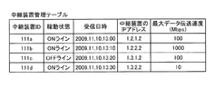
不揮発性記憶部5000には、図8に示されているような中継装置管理テーブルによって構成されている中継装置管理DB5001が構築されている。この中継装置管理テーブルでは、各中継装置30の中継装置ID毎に、各中継装置30の稼動状態、稼動状態が示される状態情報が管理システム50で受信された受信日時、中継装置30のIPアドレス、及び中継装置30における最大データ伝送速度(Mbps)が関連付けられて管理される。例えば、図8に示されている中継装置管理テーブルにおいて、中継装置IDが「111a」の中継装置30aは、稼動状態が「ONライン」で、管理システム50で状態情報が受信された日時が「2009年11月10日の13時00分」で、この中継装置30aのIPアドレスが「1.2.1.2」で、この中継装置30aにおける最大データ伝送速度が100Mbpsであることが示されている。
(Relay device management table)
In the non-volatile storage unit 5000, a relay device management DB 5001 including a relay device management table as shown in FIG. 8 is constructed. In this relay device management table, for each relay device ID of each relay device 30, the operating status of each relay device 30, the reception date and time when the management system 50 received the status information indicating the operating status, and the IP address of the relay device 30. , And the maximum data transmission rate (Mbps) in the relay device 30 are associated and managed. For example, in the relay device management table shown in FIG. 8, the relay device 30a having the relay device ID “111a” has an operating state of “ON line”, and the date and time when the management system 50 receives the state information is “ At 13:00 on November 10, 2009, it is shown that the IP address of the relay device 30a is "1.2.1.2" and the maximum data transmission rate in the relay device 30a is 100 Mbps. ing.

(端末認証管理テーブル)
更に、不揮発性記憶部5000には、図9に示されているような端末認証管理テーブルによって構成されている端末認証管理DB5002が構築されている。この端末認証管理テーブルでは、管理システム50によって管理される全ての端末10の端末ID毎に、伝送システム1にログインするためのパスワードが関連付けられて管理される。例えば、図9に示されている端末認証管理テーブルにおいて、端末10aaの端末IDは「01aa」で、パスワードは「aaaa」であることが示されている。端末認証管理テーブルの情報は、ユーザーや管理システム50の管理者が予め登録しておく。
(Terminal authentication management table)
Furthermore, in the non-volatile storage unit 5000, a terminal authentication management DB 5002 configured by a terminal authentication management table as shown in FIG. 9 is constructed. In this terminal authentication management table, a password for logging in to the transmission system 1 is associated with each terminal ID of all the terminals 10 managed by the management system 50 and managed. For example, the terminal authentication management table shown in FIG. 9 indicates that the terminal ID of the terminal 10aa is “01aa” and the password is “aaaa”. The information of the terminal authentication management table is registered in advance by the user or the administrator of the management system 50.

(端末管理テーブル)
また、不揮発性記憶部5000には、図10に示されているような端末管理テーブルによって構成されている端末管理DB5003が構築されている。この端末管理テーブルでは、各端末10の端末ID毎に、各端末10を宛先とした場合の端末名、各端末10の稼動状態、ログイン要求情報が管理システム50で受信された受信日時、及び端末10のIPアドレスが関連付けられて管理される。例えば、図10に示されている端末管理テーブルにおいて、端末IDが「01aa」の端末10aaは、端末名が「日本 東京事業所 AA端末」で、稼動状態が「ONライン(通話可能)」で、管理システム50でログイン要求情報が受信された日時が「2009年11月10日の13時40分」で、この端末10aaのIPアドレスが「1.2.1.3」であることが示されている。
(Terminal management table)
Further, in the non-volatile storage unit 5000, a terminal management DB 5003 configured by a terminal management table as shown in FIG. 10 is constructed. In this terminal management table, for each terminal ID of each terminal 10, the terminal name when each terminal 10 is the destination, the operating state of each terminal 10, the reception date and time when the login request information was received by the management system 50, and the terminal Ten IP addresses are associated and managed. For example, in the terminal management table shown in FIG. 10, the terminal 10aa with the terminal ID "01aa" has the terminal name "Japan Tokyo Office AA terminal" and the operating state "ON line (callable)". It is shown that the date and time when the login request information is received by the management system 50 is "13:40 on November 10, 2009" and the IP address of this terminal 10aa is "1.2.1.3". Has been done.

(宛先リスト管理テーブル)
更に、不揮発性記憶部5000には、図11に示されているような宛先リスト管理テーブルによって構成されている宛先リスト管理DB5004が構築されている。この宛先リスト管理テーブルでは、要求元端末ID毎に宛先端末IDが関連付けられて管理される。要求元端末IDは、通話の開始を要求する要求元端末を識別するための情報である。宛先端末IDは、通話の開始を要求する要求元端末の通信の宛先端末の候補となる宛先端末を識別するための情報である。この宛先端末の候補は、要求元端末から管理システム50に対する追加又は削除の要請により、追加又は削除されることで更新される。例えば、図11に示されている宛先リスト管理テーブルにおいて、端末IDが「01aa」である要求元端末(端末10aa)からテレビ会議における通話の開始を要求することができる宛先端末の候補は、端末IDが「01ab」の端末10ab、端末IDが「01ba」の端末10ba、及び端末IDが「01bb」の端末10bb、端末IDが「01ca」の端末10ca及び端末IDが「01db」の端末10dbであることが示されている。
(Recipient list management table)
Further, in the non-volatile storage unit 5000, a destination list management DB 5004 configured by a destination list management table as shown in FIG. 11 is constructed. In this destination list management table, a destination terminal ID is associated with each request source terminal ID and managed. The request source terminal ID is information for identifying the request source terminal that requests the start of the call. The destination terminal ID is information for identifying a destination terminal that is a candidate for the destination terminal of the communication of the request source terminal that requests the start of the call. This destination terminal candidate is updated by being added or deleted in response to a request from the requesting terminal to the management system 50 for addition or deletion. For example, in the destination list management table shown in FIG. 11, the destination terminal candidates that can request the start of the call in the video conference from the request source terminal (terminal 10aa) with the terminal ID “01aa” are the terminals. In the terminal 10ab having the ID “01ab”, the terminal 10ba having the terminal ID “01ba”, the terminal 10bb having the terminal ID “01bb”, the terminal 10ca having the terminal ID “01ca”, and the terminal 10db having the terminal ID “01db”. It has been shown to be.

(セッション管理テーブル)
また、この不揮発性記憶部5000には、図12に示されているようなセッション管理テーブルによって構成されているセッション管理DB5005が構築されている。このセッション管理テーブルでは、端末間の通信を識別するためのセッションID毎に、画像データ及び音声データの中継に使用される中継装置30の中継装置ID、要求元端末の端末ID及び宛先端末の端末IDが関連付けられて管理される。例えば、図12に示されているセッション管理テーブルにおいて、セッションID「se1」を用いて実行されたセッションで選択された中継装置30e(中継装置ID「111e」)は、端末IDが「01aa」の要求元端末(端末10aa)と、端末IDが「01ab」の宛先端末(端末10ab)と、端末IDが「01db」の宛先端末(端末10db)との間で、画像データ及び音声データを中継していることが示されている。
(Session management table)
In addition, a session management DB 5005 configured by a session management table as shown in FIG. 12 is constructed in the non-volatile storage unit 5000. In this session management table, for each session ID for identifying communication between terminals, the relay apparatus ID of the relay apparatus 30 used for relaying image data and audio data, the terminal ID of the request source terminal, and the terminal of the destination terminal. IDs are associated and managed. For example, in the session management table shown in FIG. 12, the relay device 30e (relay device ID “111e”) selected in the session executed using the session ID “se1” has the terminal ID “01aa”. The image data and the audio data are relayed between the request source terminal (terminal 10aa), the destination terminal (terminal 10ab) whose terminal ID is "01ab", and the destination terminal (terminal 10db) whose terminal ID is "01db". Have been shown.

(中継装置選択管理テーブル)
更に、不揮発性記憶部5000には、図13に示されているような中継装置選択管理テーブルによって構成されている中継装置選択管理DB5006が構築されている。この品質管理テーブルでは、管理システム50によって管理される全ての端末10の各端末IDに対して、画像データ及び音声データの中継に使用される中継装置30の中継装置IDが関連付けられて管理される。
(Relay device selection management table)
Further, in the non-volatile storage unit 5000, a relay device selection management DB 5006 configured by a relay device selection management table as shown in FIG. 13 is constructed. In this quality control table, the relay device IDs of the relay devices 30 used for relaying image data and audio data are associated with each terminal ID of all the terminals 10 managed by the management system 50 and managed. ..

(入室管理テーブル)
更に、不揮発性記憶部5000には、図14に示されているような入室管理テーブルによって構成されている入室管理DB5007が構築されている。この入室管理テーブルは、指定された一以上の端末10が参加できる第2の通信により行う会議毎に、会議を識別するための会議室IDと、指定された一以上の端末10の端末IDとが関連付けて記憶される。
(Entry control table)
Further, in the non-volatile storage unit 5000, an entry management DB 5007 configured by an entry management table as shown in FIG. 14 is constructed. This entry management table includes a conference room ID for identifying the conference and a terminal ID of the designated one or more terminals 10 for each conference held by the second communication in which the designated one or more terminals 10 can participate. Are stored in association with each other.

(会議室管理テーブル)
更に、不揮発性記憶部5000には、図15に示されているような会議室管理テーブルによって構成されている会議室管理DB5008が構築されている。この会議室管理テーブルは、指定された一以上の端末10が参加できる第2の通信により行う会議毎に、会議を識別するための会議室IDと、会議名と、当該会議室IDにより識別される第2の通信のセッションIDとが関連付けて記憶される。会議室IDは、仮想的に作成された会議室又は開催される会議を識別するための会議識別情報である。
(Meeting room management table)
Furthermore, in the non-volatile storage unit 5000, a conference room management DB 5008 including a conference room management table as shown in FIG. 15 is constructed. This conference room management table is identified by the conference room ID for identifying the conference, the conference name, and the conference room ID for each conference held by the second communication in which one or more designated terminals 10 can participate. And the session ID of the second communication that is stored. The conference room ID is conference identification information for identifying a virtually created conference room or a conference to be held.

(管理システムの各機能部)
次に、管理システム50の各機能部について詳細に説明する。なお、以下では、管理システム50の各部を説明するにあたって、図4に示されている各構成要素のうち、管理システム50の各部を実現させるための主な構成要素との関係も説明する。管理システム50は、送受信部51、端末認証部52、状態管理部53、端末抽出部54、端末状態取得部55、中継装置選択部56、セッション管理部57、会議管理部58、判定部59及び記憶・読出処理部60を有している。これら各部は、図4に示されている各構成要素のいずれかが、ROM202に記憶されているプログラムに従ったCPU201からの命令によって動作することで実現される機能又は手段である。
(Each functional part of the management system)
Next, each functional unit of the management system 50 will be described in detail. It should be noted that, in describing the respective parts of the management system 50, the relationship with the main constituent elements for realizing the respective parts of the management system 50 among the respective constituent elements shown in FIG. 4 will also be described below. The management system 50 includes a transmission/reception unit 51, a terminal authentication unit 52, a status management unit 53, a terminal extraction unit 54, a terminal status acquisition unit 55, a relay device selection unit 56, a session management unit 57, a conference management unit 58, a determination unit 59, and It has a storage/readout processing unit 60. Each of these units is a function or means realized by any one of the components shown in FIG. 4 being operated by an instruction from the CPU 201 according to a program stored in the ROM 202.

送受信部51は、図4に示されているネットワークI/F209によって実行され、通信ネットワーク2を介して他の端末、装置又はシステムと各種データの送受信を行う。 The transmission/reception unit 51 is executed by the network I/F 209 shown in FIG. 4, and transmits/receives various data to/from other terminals, devices or systems via the communication network 2.

例えば、送受信部51は、後述する宛先端末状態一覧画像(図18)から、端末10のユーザーが宛先端末を指定して通信を開始するときに、入室発信による開始要求情報又は通常発信による開始要求情報を端末10から受信する。 For example, the transmission/reception unit 51, when the user of the terminal 10 specifies a destination terminal and starts communication from a destination terminal status list image (FIG. 18) described later, start request information by entering room or start request by normal calling. Information is received from the terminal 10.

また、送受信部51は、端末10から開始要求情報を受信した後に、通信を識別するためのセッションID及び中継装置接続情報を当該端末10に送信する。 After receiving the start request information from the terminal 10, the transmitter/receiver 51 transmits the session ID for identifying the communication and the relay device connection information to the terminal 10.

また、送受信部51は、通信の要求元の端末10から開始要求情報を受信した後に、当該通信の宛先の端末10に、当該開始要求情報、中継装置接続情報、及び管理システム50のIPアドレスを送信する。 Further, the transmission/reception unit 51 receives the start request information from the communication requesting terminal 10 and then transmits the start request information, the relay device connection information, and the IP address of the management system 50 to the communication destination terminal 10. Send.

また、送受信部51は、通信の宛先の端末10から開始応答情報を受信した後に、通信の要求元の端末10に当該開始応答情報を送信する。 Further, the transmission/reception unit 51 transmits the start response information to the communication requesting terminal 10 after receiving the start response information from the communication destination terminal 10.

端末認証部52は、送受信部51を介して受信されたログイン要求情報に含まれている端末ID及びパスワードを検索キーとし、不揮発性記憶部5000の端末認証管理テーブル(図9参照)を検索し、端末認証管理テーブルに同一の端末ID及びパスワードが管理されているかを判断することによって端末認証を行う。 The terminal authentication unit 52 uses the terminal ID and password included in the login request information received via the transmission/reception unit 51 as a search key to search the terminal authentication management table (see FIG. 9) of the non-volatile storage unit 5000. The terminal authentication is performed by determining whether the same terminal ID and password are managed in the terminal authentication management table.

状態管理部53は、ログイン要求してきた要求元端末の稼動状態を管理すべく、端末管理テーブル(図10参照)に、この要求元端末の端末ID、要求元端末の端末名、要求元端末の稼動状態、管理システム50がログイン要求情報を受信した受信日時、及び要求元端末のIPアドレスを関連付けて記憶して管理する。そのため、状態管理部53は、図4に示されているCPU201からの命令によって、図6に示される状態設定部53a及び状態取得部53bを実現する。 The state management unit 53 uses the terminal management table (see FIG. 10) to manage the operating state of the request source terminal that has made the login request, by using the terminal ID of the request source terminal, the terminal name of the request source terminal, and the request source terminal. The operating state, the reception date and time when the management system 50 receives the login request information, and the IP address of the request source terminal are stored in association with each other and managed. Therefore, the state management unit 53 realizes the state setting unit 53a and the state acquisition unit 53b shown in FIG. 6 by the instruction from the CPU 201 shown in FIG.

このうち、状態設定部53aは、端末10の状態が変更されたことを示す情報を端末10から受信した場合に、端末管理テーブル(図10参照)の当該端末10の状態情報を設定(変更)する。例えば、端末10の利用者が端末10の電源スイッチ109をOFFの状態からONにすると、当該端末10は、電源をONにする旨の状態情報を管理システム50に送信する。状態設定部53aは、送受信部51を介して当該状態情報を受信したときに、端末管理テーブル(図10参照)の当該端末10の稼動状態を「OFFライン」から「ONライン(通話可能)」に変更する。また、利用者が端末10の電源スイッチ109をONの状態からOFFにすると、当該端末10は、電源をOFFにする旨の状態情報を管理システム50に送信する。状態設定部53aは、送受信部51を介して当該状態情報を受信したときに、端末管理テーブル(図10参照)の当該端末10の稼動状態を「ONライン(通話可能)」から「OFFライン」に変更する。 Of these, the state setting unit 53a sets (changes) the state information of the terminal 10 in the terminal management table (see FIG. 10) when the information indicating that the state of the terminal 10 has been changed is received from the terminal 10. To do. For example, when the user of the terminal 10 turns on the power switch 109 of the terminal 10 from the off state, the terminal 10 transmits to the management system 50 the state information indicating that the power is turned on. When the status setting unit 53a receives the status information via the transmitting/receiving unit 51, the status setting unit 53a changes the operating status of the terminal 10 in the terminal management table (see FIG. 10) from “OFF line” to “ON line (communication available)”. Change to. When the user turns off the power switch 109 of the terminal 10 from the on state, the terminal 10 transmits state information to the management system 50 to the effect that the power is turned off. When the status setting unit 53a receives the status information via the transmission/reception unit 51, the status setting unit 53a changes the operating status of the terminal 10 in the terminal management table (see FIG. 10) from “ON line (communication available)” to “OFF line”. Change to.

状態取得部53bは、宛先端末の状態情報が必要な宛先リスト要求情報などを要求元端末から受信した場合に、要求元端末及び宛先端末の少なくとも一方の状態情報を端末管理テーブル(図10参照)から取得する。 The status acquisition unit 53b, when receiving the destination list request information or the like that requires the status information of the destination terminal from the request source terminal, displays the status information of at least one of the request source terminal and the destination terminal in the terminal management table (see FIG. 10). To get from.

端末抽出部54は、ログイン要求した要求元端末の端末IDを検索キーとして、宛先リスト管理テーブル(図11参照)の要求元端末IDを検索し、検索されたレコードの宛先端末IDを抽出する。端末抽出部54は、抽出した宛先端末IDにより識別される端末10を、要求元端末と通話することができる宛先端末の候補として抽出する。 The terminal extraction unit 54 searches for the request source terminal ID in the destination list management table (see FIG. 11) using the terminal ID of the request source terminal that made the login request as a search key, and extracts the destination terminal ID of the retrieved record. The terminal extraction unit 54 extracts the terminal 10 identified by the extracted destination terminal ID as a candidate for a destination terminal that can communicate with the request source terminal.

端末状態取得部55は、上記端末抽出部54によって抽出された宛先端末の候補の端末ID毎に、当該端末IDを検索キーとして、端末管理テーブル(図10参照)の端末IDを検索し、検索されたレコードの稼動状態を読み出す。これにより、端末状態取得部55は、ログイン要求してきた要求元端末と通話することができる宛先端末の候補の稼動状態を取得することができる。 The terminal state acquisition unit 55 searches for a terminal ID in the terminal management table (see FIG. 10) using the terminal ID as a search key for each terminal ID of the destination terminal candidate extracted by the terminal extraction unit 54, and searches. Reads the operating status of the specified record. As a result, the terminal status acquisition unit 55 can acquire the operating status of the candidate of the destination terminal that can communicate with the request source terminal that has made the login request.

中継装置選択部56は、複数の中継装置30から最終的に1つの中継装置30に絞り込むための処理を行う。そのため、中継装置選択部56は、図4に示されているCPU201からの命令によって、図7に示されるセッションID生成部56a、中継装置抽出部56b及び選択部56cを実現する。 The relay device selection unit 56 performs a process of finally narrowing down from the plurality of relay devices 30 to one relay device 30. Therefore, the relay device selection unit 56 realizes the session ID generation unit 56a, the relay device extraction unit 56b, and the selection unit 56c shown in FIG. 7 by the command from the CPU 201 shown in FIG.

このうち、セッションID生成部56aは、端末間で通話データが通信されるセッションを識別するためのセッションIDを生成する。中継装置抽出部56bは、要求元端末から送られてきた開始要求情報に含まれている要求元端末の端末ID、及宛先端末の端末IDに基づいて、中継装置選択管理テーブル(図13参照)を検索することにより、対応するそれぞれの中継装置IDを抽出する。選択部56cは、中継装置管理テーブル(図8参照)で管理されている中継装置30のうち、稼動状態が「ONライン」となっている中継装置30の中継装置IDを選択することにより、中継装置30の選択を行う。 Of these, the session ID generation unit 56a generates a session ID for identifying a session in which call data is communicated between terminals. The relay device extraction unit 56b, based on the terminal ID of the request source terminal and the terminal ID of the destination terminal included in the start request information sent from the request source terminal, the relay device selection management table (see FIG. 13). By searching for each corresponding relay device ID. The selecting unit 56c selects the relay device ID of the relay device 30 whose operating state is “ON line” among the relay devices 30 managed by the relay device management table (see FIG. 8), thereby performing the relay. The device 30 is selected.

セッション管理部57は、不揮発性記憶部5000のセッション管理テーブル(図12参照)に、セッションID生成部56aで生成されたセッションID、要求元端末の端末ID、及び宛先端末の端末IDを関連付けて記憶して管理する。また、セッション管理部57は、セッション管理テーブルに対して、セッションID毎に、最終的に1つに選択された中継装置30の中継装置IDを記憶して管理する。また、セッション管理部57は、会議室IDにより識別される第2の通信のセッションIDを、会議室管理テーブルの当該会議室IDに関連付けて記憶する。 The session management unit 57 associates the session management table (see FIG. 12) of the non-volatile storage unit 5000 with the session ID generated by the session ID generation unit 56a, the terminal ID of the request source terminal, and the terminal ID of the destination terminal. Remember and manage. Further, the session management unit 57 stores and manages, for each session ID, the relay device ID of the relay device 30 finally selected as one, for each session ID. In addition, the session management unit 57 stores the session ID of the second communication identified by the conference room ID in association with the conference room ID in the conference room management table.

会議管理部58は、不揮発性記憶部5000の入室管理テーブル(図14参照)に、会議室ID、及び端末IDを関連付けて記憶して管理する。また、会議管理部58は、不揮発性記憶部5000の会議室管理テーブル(図15参照)に、会議室ID、会議名及びセッションIDを関連付けて記憶して管理する。 The conference management unit 58 associates and stores the conference room ID and the terminal ID in the entry management table (see FIG. 14) of the non-volatile storage unit 5000. Further, the conference management unit 58 stores the conference room ID, the conference name, and the session ID in association with each other in the conference room management table (see FIG. 15) of the non-volatile storage unit 5000 for management.

判定部59は、通信の要求元の端末10から、送受信部51を介して、会議室IDにより識別される第2の通信の開始を示す入室発信開始要求を受信する。入室発信開始要求は、要求元端末の端末ID及び入室する会議室を特定するための情報(会議室ID又は宛先端末の端末ID)を含む。判定部59は、入室発信開始要求に含まれる会議室を特定するための情報から、入室する会議室の会議室IDを特定し、入室発信開始要求に含まれる要求元の端末10の端末IDが当該会議室IDに関連付けられているか否かを判定する。判定部59は、関連付けられている場合、当該入室発信開始要求に係る第2の通信のセッション管理処理をセッション管理部57に依頼する。当該セッション管理処理は、セッションの生成(宛先端末の稼動状態が「ONライン(通話可能)」の場合)に係る処理、又は既存のセッションへの参加(宛先端末の稼動状態が「ONライン(通話中)」の場合)に係る処理である。 The determination unit 59 receives, via the transmission/reception unit 51, the entrance request for starting entry indicating the start of the second communication, which is identified by the conference room ID, from the terminal 10 that is the source of the communication request. The request to start entering the room includes the terminal ID of the request source terminal and information for specifying the meeting room to enter (the meeting room ID or the terminal ID of the destination terminal). The determination unit 59 identifies the conference room ID of the conference room to enter from the information for identifying the conference room included in the entry transmission start request, and determines the terminal ID of the requesting terminal 10 included in the entry transmission start request. It is determined whether or not it is associated with the conference room ID. If the determination unit 59 is associated, the determination unit 59 requests the session management unit 57 to perform the session management process of the second communication related to the entry call initiation request. The session management processing is processing related to generation of a session (when the operation status of the destination terminal is “ON line (call enabled)”) or participation in an existing session (when the operation status of the destination terminal is “ON line (call enabled)”). Middle)”).

記憶・読出処理部60(宛先端末情報管理部に相当)は、不揮発性記憶部5000又は揮発性記憶部5100に各種データを記憶したり、不揮発性記憶部5000又は揮発性記憶部5100に記憶された各種データを読み出す処理を行う。 The storage/readout processing unit 60 (corresponding to the destination terminal information management unit) stores various data in the non-volatile storage unit 5000 or the volatile storage unit 5100, or is stored in the non-volatile storage unit 5000 or the volatile storage unit 5100. The process of reading various data is performed.

<<実施形態の処理または動作>>
以上が、本実施形態に係る伝送システム1の構成及び機能(又は手段)の説明であり、続いて、図16乃至図36を用いて、本実施形態に係る伝送システム1における処理方法を説明する。
<<Process or Operation of Embodiment>>
The above is a description of the configuration and functions (or means) of the transmission system 1 according to the present embodiment, and subsequently, the processing method in the transmission system 1 according to the present embodiment will be described using FIGS. 16 to 36. ..

まず、図16を用いて、各中継装置30から管理システム50に送信された各中継装置30の状態を示す状態情報を管理する処理を説明する。図16は、各中継装置30の稼動状態を示す状態情報を管理する処理を示したシーケンス図である。まず、各中継装置30では、図5に示されている状態検知部32が、自装置である中継装置30の稼動状態を定期的に検知している(ステップS1−1〜S1−4)。そして、管理システム50側で各中継装置30の稼動状態をリアルタイムで管理させるべく、各中継装置30の送受信部31は、定期的に通信ネットワーク2を介して管理システム50へ各状態情報を送信する(ステップS2−1〜S2−4)。これら各状態情報には、中継装置30毎の中継装置IDと、これら各中継装置IDに係る中継装置30の状態検知部32で検知された稼動状態とが含まれている。なお、本実施形態では、中継装置(30a,30b,30d)は、正常に稼動して「ONライン」となっている一方で、中継装置30cは稼働中ではあるが、中継装置30cの中継動作を実行するためのプログラムに何らかの不具合が生じて、「OFFライン」となっている場合が示されている。 First, a process of managing the state information indicating the state of each relay device 30 transmitted from each relay device 30 to the management system 50 will be described with reference to FIG. FIG. 16 is a sequence diagram showing a process of managing state information indicating the operating state of each relay device 30. First, in each relay device 30, the state detection unit 32 illustrated in FIG. 5 periodically detects the operating state of the relay device 30 that is the self device (steps S1-1 to S1-4). Then, in order for the management system 50 side to manage the operating state of each relay device 30 in real time, the transmission/reception unit 31 of each relay device 30 periodically transmits each status information to the management system 50 via the communication network 2. (Steps S2-1 to S2-4). Each of these pieces of state information includes a relay device ID for each relay device 30 and an operating state detected by the state detection unit 32 of the relay device 30 related to each relay device ID. In the present embodiment, the relay devices (30a, 30b, 30d) are normally operating and are in the “ON line”, while the relay device 30c is in operation, but the relay operation of the relay device 30c is performed. There is shown a case in which the program for executing is in the "OFF line" due to some trouble.

次に、管理システム50では、各中継装置30から送られて来た各状態情報を送受信部51が受信し、記憶・読出処理部60を介して不揮発性記憶部5000の中継装置管理テーブル(図8参照)に、中継装置ID毎に状態情報を記憶して管理する(ステップS3−1〜S3−4)。これにより、図8に示されるような中継装置管理テーブルに対して、中継装置ID毎に「ONライン」、「OFFライン」、又は「故障中」のいずれかの稼動状態が記憶されて管理される。またこの際に、中継装置ID毎に、管理システム50で状態情報が受信された受信日時も記憶されて管理される。なお、中継装置30から状態情報が送られない場合には、図8に示されている中継装置管理テーブルの各レコードにおける稼動状態のフィールド部分及び受信日時のフィールド部分が空白になるか、又は、前回の受信時の稼動状態及び受信日時をそれぞれ示す。 Next, in the management system 50, the transmission/reception unit 51 receives each status information sent from each relay device 30, and the relay device management table of the nonvolatile storage unit 5000 (see FIG. 8), the state information is stored and managed for each relay device ID (steps S3-1 to S3-4). As a result, in the relay device management table as shown in FIG. 8, the operating state of either “ON line”, “OFF line”, or “in failure” is stored and managed for each relay device ID. It At this time, the reception date and time at which the status information is received by the management system 50 is also stored and managed for each relay device ID. If status information is not sent from the relay device 30, the field part of the operating status and the field part of the reception date and time in each record of the relay device management table shown in FIG. 8 become blank, or The operating status and the reception date and time at the time of the previous reception are shown.

次に、図17を用いて、伝送システム1における画像データ、音声データ、及び各種管理情報の送受信の状態を示した概念を説明する。図17は、伝送システム1における画像データ、音声データ、及び各種管理情報の送受信の状態を示した概念図である。図17に示されているように、伝送システム1では、端末10Aと端末10Bと端末10Cの間では、管理システム50を介して、各種の管理情報を送受信するための管理情報用セッションseiが確立される。また、端末10Aと端末10Bと端末10Cの間では、中継装置30を介して、高解像度の画像データ、中解像度の画像データ、低解像度の画像データ、及び音声データの4つの各データを送受信するための4つのセッションが確立される。ここでは、これら4つのセッションをまとめて、画像・音声データ用セッションsedとして示している。 Next, with reference to FIG. 17, a concept showing a transmission/reception state of image data, audio data, and various management information in the transmission system 1 will be described. FIG. 17 is a conceptual diagram showing a transmission/reception state of image data, audio data, and various management information in the transmission system 1. As shown in FIG. 17, in the transmission system 1, a management information session sei for transmitting and receiving various management information is established between the terminals 10A, 10B, and 10C via the management system 50. To be done. Further, between the terminal 10A, the terminal 10B, and the terminal 10C, four pieces of data of high-resolution image data, medium-resolution image data, low-resolution image data, and audio data are transmitted and received via the relay device 30. 4 sessions are established. Here, these four sessions are collectively shown as an image/audio data session sed.

次に、図18及び図19を用いて、宛先端末状態一覧情報を含む画像(宛先端末状態一覧画像)を、端末10aaに表示する処理について説明する。 Next, a process of displaying an image including the destination terminal state list information (destination terminal state list image) on the terminal 10aa will be described with reference to FIGS. 18 and 19.

図18は、宛先端末状態一覧情報を含む画像を示す図である。宛先端末状態一覧画像は、通信の要求元端末に関連付けられた宛先端末を示す情報と、宛先端末に会議室が関連付けられているか否かを示す情報(画像1504)とを含む宛先端末状態情報を一以上含む宛先端末状態一覧情報を示す画像である。画像1504がある宛先端末情報は、当該宛先端末が参加できる第2の通信(仮想的な会議室)が管理システム50に登録されていることを示す。また、図18の宛先端末状態一覧画像の例では、宛先端末の稼動状態を示す稼動状態情報(画像1501、画像1502又は画像1503)も示している。画像1501は、当該宛先端末が「ONライン(通話可能)」であることを示す。画像1502は、当該宛先端末が「ONライン(通話中)」であることを示す。画像1503は、当該宛先端末が「OFFライン」であることを示す。 FIG. 18 is a diagram showing an image including destination terminal status list information. The destination terminal status list image includes destination terminal status information including information indicating a destination terminal associated with the communication request source terminal and information indicating whether a conference room is associated with the destination terminal (image 1504). It is an image showing one or more destination terminal status list information. The destination terminal information including the image 1504 indicates that the second communication (virtual conference room) in which the destination terminal can participate is registered in the management system 50. The example of the destination terminal status list image in FIG. 18 also shows operating status information (image 1501, image 1502, or image 1503) indicating the operating status of the destination terminal. An image 1501 indicates that the destination terminal is “ON line (communication possible)”. An image 1502 indicates that the destination terminal is “ON line (during a call)”. The image 1503 indicates that the destination terminal is “OFF line”.

図19は、宛先端末状態一覧情報を含む画像を、端末に表示する処理を示したシーケンス図である。なお、図19において、端末10と管理システム50との間の通信は、全て管理情報用セッションseiを使用して行われる。 FIG. 19 is a sequence diagram showing a process of displaying an image including the destination terminal status list information on the terminal. In FIG. 19, all communication between the terminal 10 and the management system 50 is performed using the management information session sei.

まず、端末10aaの利用者が、図3に示されている電源スイッチ109をONにすると、図5に示されている操作入力受付部12が電源ONを受け付けて、電源をONにする(ステップS21)。そして、ログイン要求部13は、上記電源ONの受信を契機とし、送受信部11から通信ネットワーク2を介して管理システム50に、ログイン要求を示すログイン要求情報を自動的に送信する(ステップS22)。このログイン要求情報には、要求元としての自端末である端末10aaを識別するための端末ID、及びパスワードが含まれている。これら端末ID、及びパスワードは、記憶・読出処理部17を介して不揮発性記憶部1000から読み出されて、送受信部11に送られたデータである。なお、端末10aaから管理システム50へログイン要求情報が送信される際は、受信側である管理システム50は、送信側である端末10aaのIPアドレスを把握することができる。 First, when the user of the terminal 10aa turns on the power switch 109 shown in FIG. 3, the operation input receiving unit 12 shown in FIG. 5 receives the power ON and turns the power ON (step S21). Then, the login request unit 13 automatically transmits the login request information indicating the login request from the transmission/reception unit 11 to the management system 50 via the communication network 2 upon receiving the power ON (step S22). This login request information includes a terminal ID for identifying the terminal 10aa, which is the requester's own terminal, and a password. These terminal ID and password are data read from the non-volatile storage unit 1000 via the storage/readout processing unit 17 and sent to the transmission/reception unit 11. When the login request information is transmitted from the terminal 10aa to the management system 50, the management system 50 on the reception side can recognize the IP address of the terminal 10aa on the transmission side.

次に、管理システム50の端末認証部52は、送受信部51を介して受信したログイン要求情報に含まれている端末ID及びパスワードを検索キーとして、不揮発性記憶部5000の端末認証管理テーブル(図9参照)を検索し、端末認証管理DB5002に検索キーと一致する端末ID及びパスワードがあるか否かをを判定することによって端末認証を行う(ステップS23)。 Next, the terminal authentication unit 52 of the management system 50 uses the terminal ID and password included in the login request information received via the transmission/reception unit 51 as a search key, and stores the terminal authentication management table (see FIG. 9)), and terminal authentication is performed by determining whether or not there is a terminal ID and password matching the search key in the terminal authentication management DB 5002 (step S23).

当該検索キーと一致する端末ID及びパスワードが、端末認証管理DB5002にある場合、状態管理部53は、当該検索キーの端末IDで端末管理テーブル(図10参照)の端末IDを検索し、検索されたレコードの受信日時フィールドにログイン要求情報を受信した日時を設定する。また、状態管理部53は、検索されたレコードの端末のIPアドレスフィールドに、ログイン要求情報に含まれるIPアドレスを記憶する(ステップS24−1)。これにより、図10に示されている端末管理テーブルには、端末ID「01aa」に、受信日時「2009.11.10.13:40」及び端末IPアドレス「1.2.1.3」が関連付けて管理されることになる。 When the terminal ID and password that match the search key are in the terminal authentication management DB 5002, the state management unit 53 searches the terminal ID in the terminal management table (see FIG. 10) with the terminal ID of the search key and is searched. The date and time when the login request information is received is set in the reception date and time field of the record that has been recorded. The state management unit 53 also stores the IP address included in the login request information in the IP address field of the terminal of the retrieved record (step S24-1). As a result, in the terminal management table shown in FIG. 10, the terminal ID “01aa”, the reception date and time “2009.11.10.13:40”, and the terminal IP address “1.2.1.3” are displayed. It will be managed in association with each other.

続いて、状態管理部53の状態設定部53aが、検索されたレコードの稼動状態フィールドに端末10aaの稼動状態「ONライン(通話可能)」を設定する(ステップS24−2)。これにより、図10に示されている端末管理テーブルには、端末ID「01aa」に、稼動状態「ONライン(通話可能)」が関連付けて管理されることになる。 Subsequently, the state setting unit 53a of the state management unit 53 sets the operating state "ON line (communication possible)" of the terminal 10aa in the operating state field of the retrieved record (step S24-2). As a result, the terminal management table shown in FIG. 10 manages the terminal ID “01aa” in association with the operating state “ON line (communication possible)”.

そして、管理システム50の送受信部51は、上記端末認証部52によって得られた認証結果が示された認証結果情報を、通信ネットワーク2を介して、上記ログイン要求してきた要求元端末(端末10aa)に送信する(ステップS25)。本実施形態では、端末認証部52によって正当な利用権限を有する端末であると判断された場合につき、以下続けて説明する。 Then, the transmission/reception unit 51 of the management system 50 transmits the authentication result information indicating the authentication result obtained by the terminal authentication unit 52 via the communication network 2 to the request source terminal (terminal 10aa) that has made the login request. (Step S25). In the present embodiment, a case in which the terminal authentication unit 52 determines that the terminal has a valid usage right will be continuously described below.

端末10aaでは、正当な利用権限を有する端末であると判断されたことを示す認証結果情報を受信すると、送受信部11が通信ネットワーク2を介して管理システム50へ、宛先リストを要求する旨が示された宛先リスト要求情報を送信する(ステップS26)。これにより、管理システム50の送受信部51は、宛先リスト要求情報を受信する。 When the terminal 10aa receives the authentication result information indicating that the terminal 10aa has been determined to have the proper usage authority, the transmitting/receiving unit 11 indicates to the management system 50 via the communication network 2 that the destination list is requested. The sent destination list request information is transmitted (step S26). As a result, the transmission/reception unit 51 of the management system 50 receives the destination list request information.

次に、端末抽出部54は、ログイン要求した要求元端末(端末10aa)の端末ID「01aa」を検索キーとして、宛先リスト管理テーブル(図11参照)を検索し、要求元端末(端末10aa)と通話することができる宛先端末の候補の端末IDを読み出すことによって抽出する(ステップS27)。また、端末抽出部54は、抽出された端末IDを検索キーとして、端末管理テーブル(図10参照)を検索し、この端末IDに対応する宛先名を読み出すことによって抽出する。ここでは、要求元端末(端末10aa)の端末ID「01aa」に対応する宛先端末(10ab,10ba,10bb,10ca及び10db)のそれぞれの端末ID(「01ab」、「01ba」、「01bb」、「01ca」及び「01db」)と、これらに対応する端末名(「日本 東京事業所 AB端末」、「日本 大阪事業所 BA端末」、「日本 大阪事業所 BB端末」、「アメリカ ニューヨーク事業所 CA端末」及び「アメリカ ワシントン事業所 DB端末」)が抽出される。 Next, the terminal extraction unit 54 searches the destination list management table (see FIG. 11) using the terminal ID “01aa” of the request source terminal (terminal 10aa) that made the login request as a search key, and the request source terminal (terminal 10aa). It extracts by reading out the terminal ID of the candidate of the destination terminal which can talk with (step S27). Further, the terminal extraction unit 54 searches the terminal management table (see FIG. 10) using the extracted terminal ID as a search key, and extracts the destination name corresponding to this terminal ID by reading. Here, the terminal IDs of the destination terminals (10ab, 10ba, 10bb, 10ca, and 10db) corresponding to the terminal ID “01aa” of the request source terminal (terminal 10aa) (“01ab”, “01ba”, “01bb”, “01ca” and “01db”) and terminal names corresponding to these (“Japan Tokyo office AB terminal”, “Japan Osaka office BA terminal”, “Japan Osaka office BB terminal”, “New York office CA of the United States”) "Terminal" and "Washington, USA DB terminal") are extracted.

次に、管理システム50の記憶・読出処理部60は、不揮発性記憶部5000から宛先端末の一覧を示す画像の表示形式を表すレイアウト情報を読み出す(ステップS28)と共に、このレイアウト情報及び上記端末抽出部54によって抽出された端末ID及び宛先名を含めた「宛先リスト情報(レイアウト情報、端末ID、宛先名)」を、要求元端末(端末10aa)に送信する(ステップS29)。これにより、要求元端末(端末10aa)では、送受信部11が宛先リスト情報を受信し、記憶・読出処理部17が揮発性記憶部1100へ宛先リスト情報を記憶する(ステップS30)。 Next, the storage/readout processing unit 60 of the management system 50 reads out the layout information indicating the display format of the image showing the list of the destination terminals from the non-volatile storage unit 5000 (step S28), and at the same time, extracts the layout information and the terminal. The "destination list information (layout information, terminal ID, destination name)" including the terminal ID and the destination name extracted by the unit 54 is transmitted to the request source terminal (terminal 10aa) (step S29). As a result, in the request source terminal (terminal 10aa), the transmission/reception unit 11 receives the destination list information, and the storage/read processing unit 17 stores the destination list information in the volatile storage unit 1100 (step S30).

このように、本実施形態では、各端末10で宛先リスト情報を管理するのではなく、管理システム50が全ての端末の宛先リスト情報を一元管理している。よって、伝送システム1に新たな端末10が含まれるようになったり、既に含まれている端末10に替えて新機種の端末10を含めるようになったり、宛先一覧の表示の見栄え等を変更することになった場合でも、管理システム50側で一括して対応するため、各端末10側で宛先リスト情報の変更を行う手間を省くことができる。 As described above, in this embodiment, the management system 50 centrally manages the destination list information of all the terminals, instead of managing the destination list information in each terminal 10. Therefore, a new terminal 10 is included in the transmission system 1, a new model terminal 10 is included in place of the terminal 10 that is already included, and the appearance of the destination list display is changed. Even if this happens, the management system 50 side will deal with it collectively, so that it is possible to save the trouble of changing the destination list information on each terminal 10 side.

また、管理システム50の端末状態取得部55は、上記端末抽出部54によって抽出された宛先端末の候補の端末ID(「01ab」、「01ba」、「01bb」、「01ca」及び「01db」)を検索キーとして、端末管理テーブル(図10参照)を検索し、上記端末抽出部54によって抽出された端末ID毎に、対応する稼動状態を読み出すことにより、宛先候補としての端末(10ab,10ba,10bb,10ca及び10db)の各稼動状態を取得する(ステップS31)。 Further, the terminal status acquisition unit 55 of the management system 50 uses the terminal IDs of the destination terminal candidates extracted by the terminal extraction unit 54 (“01ab”, “01ba”, “01bb”, “01ca”, and “01db”). Using the search key as a search key, the terminal management table (see FIG. 10) is searched, and the corresponding operating state is read for each terminal ID extracted by the terminal extraction unit 54, whereby terminals (10ab, 10ba, Each operating state of 10bb, 10ca, and 10db is acquired (step S31).

次に、送受信部51は、上記ステップS31で検索キーとして使用された端末ID(「01ab」、「01ba」、「01bb」、「01ca」及び「01db」)と、対応する宛先端末(10ab,10ba,10bb,10ca及び10db)の稼動状態とが含まれた「端末の状態情報」を、通信ネットワーク2を介して要求元端末(端末10aa)に送信する(ステップS32)。 Next, the transmitting/receiving unit 51 uses the terminal IDs (“01ab”, “01ba”, “01bb”, “01ca”, and “01db”) used as the search key in step S31 and the corresponding destination terminals (10ab, The "terminal status information" including the operating statuses of 10ba, 10bb, 10ca and 10db) is transmitted to the request source terminal (terminal 10aa) via the communication network 2 (step S32).

次に、要求元端末(端末10aa)の記憶・読出処理部17は、管理システム50から受信した端末の状態情報を揮発性記憶部1100に記憶する(ステップS33)。これにより、要求元端末(端末10aa)と通話することができる宛先端末の候補である端末10の現時点のそれぞれの稼動状態を取得することができる。 Next, the storage/read processing unit 17 of the request source terminal (terminal 10aa) stores the terminal status information received from the management system 50 in the volatile storage unit 1100 (step S33). As a result, it is possible to acquire the current operating states of the terminals 10 that are candidates for the destination terminals that can talk with the request source terminal (terminal 10aa).

また、管理システム50の会議管理部58は、上記端末抽出部54によって抽出された宛先端末の候補の端末ID(「01ab」、「01ba」、「01bb」、「01ca」及び「01db」)を検索キーとして、入室管理テーブル(図14参照)を検索し、上記端末抽出部54によって抽出された端末ID毎に、当該端末IDと関連付けられた会議室IDがある場合には、当該会議室IDを読み出す(ステップS34)。 In addition, the conference management unit 58 of the management system 50 outputs the terminal IDs (“01ab”, “01ba”, “01bb”, “01ca”, and “01db”) of the destination terminal candidates extracted by the terminal extraction unit 54. As a search key, the entry management table (see FIG. 14) is searched, and if each terminal ID extracted by the terminal extraction unit 54 has a meeting room ID associated with the terminal ID, the meeting room ID Is read (step S34).

次に、管理システム50の会議管理部58は、送受信部51を介して、端末IDと、当該端末IDに関連付けられた会議室IDとを含む会議室存在情報を端末10aaに送信する(ステップS35)。次に、要求元端末(端末10aa)の記憶・読出処理部17は、送受信部11を介して、管理システム50から受信した会議室存在情報を揮発性記憶部1100に記憶する(ステップS36)。次に、端末10aaの宛先リスト作成部18は、宛先リスト情報、状態情報及び会議室存在情報に基づいて宛先リスト(宛先端末状態一覧情報)を作成する。次に、要求元端末(端末10aa)の表示制御部16は、当該宛先リストを宛先端末状態一覧画像(図18参照)として、図3に示されているディスプレイ120に表示する(ステップS37)。 Next, the conference management unit 58 of the management system 50 transmits the conference room presence information including the terminal ID and the conference room ID associated with the terminal ID to the terminal 10aa via the transmission/reception unit 51 (step S35). ). Next, the storage/read processing unit 17 of the request source terminal (terminal 10aa) stores the conference room presence information received from the management system 50 via the transmission/reception unit 11 in the volatile storage unit 1100 (step S36). Next, the destination list creation unit 18 of the terminal 10aa creates a destination list (destination terminal status list information) based on the destination list information, the status information, and the conference room presence information. Next, the display control unit 16 of the request source terminal (terminal 10aa) displays the destination list on the display 120 shown in FIG. 3 as a destination terminal status list image (see FIG. 18) (step S37).

以上の処理により、管理システム50は、図18の宛先端末状態一覧情報を含む画像を端末10aaのディスプレイ120aaに表示させる。本実施形態の宛先端末状態一覧画像では、宛先端末に関連付けられた会議室があるか否かを示す情報を、宛先端末状態情報毎に表示される会議室アイコンの有無(画像1504)により表現する。 Through the above processing, the management system 50 causes the display 120aa of the terminal 10aa to display an image including the destination terminal status list information of FIG. In the destination terminal status list image of this embodiment, information indicating whether or not there is a conference room associated with the destination terminal is represented by the presence or absence of a conference room icon displayed for each destination terminal status information (image 1504). ..

なお、図19の説明では、管理システム50は、宛先リスト情報の送信(ステップS29)、端末の状態情報の送信(ステップS32)、及び会議室存在情報の送信(ステップS35)を別々に行っている。しかしながら、管理システム50は、これらの情報の送信を一度に行ってもよい。また、管理システム50は、上述のステップS37で端末10aaが作成した宛先リストを作成し、当該宛先リストを端末10aaに送信してもよい。すなわち、端末10aa側で宛先リストを作成せずに、管理システム50側で宛先リストを作成してもよい。 In the description of FIG. 19, the management system 50 separately transmits the destination list information (step S29), the terminal status information (step S32), and the conference room presence information (step S35). There is. However, the management system 50 may transmit these pieces of information at once. In addition, the management system 50 may create the destination list created by the terminal 10aa in step S37 described above and send the destination list to the terminal 10aa. That is, the destination list may be created on the management system 50 side without creating the destination list on the terminal 10aa side.

続いて、図20を用いて、端末が他の端末との通信(仮想的な会議室を使用しない第1の通信)の開始を要求する場合の処理を説明する。図20は、通信の開始を要求する処理を示したシーケンス図である。なお、図20において、端末10と管理システム50との間の通信は、全て管理情報用セッションseiを使用して行われる。また、本実施形態においては、要求元端末(端末10aa)は、宛先端末一覧画像(図18参照)に示された宛先の候補としての端末10のうち、稼動状態が「ONライン(通話可能)」である端末(端末10ab及び10db)の少なくとも一つと通信の開始を要求することができる。そこで、以下では、要求元端末(端末10aa)の利用者が、宛先端末(端末10ab及び10db)と通話を開始することを選択した場合について説明する。 Next, with reference to FIG. 20, a process in the case where a terminal requests the start of communication with another terminal (first communication without using a virtual conference room) will be described. FIG. 20 is a sequence diagram showing a process of requesting the start of communication. In FIG. 20, all communication between the terminal 10 and the management system 50 is performed using the management information session sei. Further, in the present embodiment, the request source terminal (terminal 10aa) has the operating state of “ON line (communication possible)” among the terminals 10 as the destination candidates shown in the destination terminal list image (see FIG. 18). It is possible to request the start of communication with at least one of the terminals (terminals 10ab and 10db) that are ". Therefore, a case will be described below in which the user of the request source terminal (terminal 10aa) selects to start a call with the destination terminal (terminals 10ab and 10db).

まず、要求元端末(端末10aa)の利用者が図3に示されている操作ボタン108を押下して宛先端末(端末10ab)と宛先端末(端末10db)とを選択すると、図5に示されている操作入力受付部12は、端末10ab及び端末10dbとの通話を開始する要求を受け付ける(ステップS41)。そして、端末10aaの送受信部11は、要求元端末(端末10aa)の端末ID「01aa」、宛先端末(端末10ab)の端末ID「01ab」、宛先端末(端末10db)の端末ID「01db」、及び第1の通信による通話の開始を要求する旨を示す情報「Invite」が含まれる開始要求情報を、管理システム50へ送信する(ステップS42)。これにより、管理システム50の送受信部51は、上記開始要求情報を受信すると共に、送信元である要求元端末(端末10aa)のIPアドレス「1.2.1.3」を把握することになる。 First, when the user of the request source terminal (terminal 10aa) presses the operation button 108 shown in FIG. 3 to select the destination terminal (terminal 10ab) and the destination terminal (terminal 10db), it is shown in FIG. The operation input accepting unit 12 accepting the request accepts a request to start a call with the terminals 10ab and 10db (step S41). Then, the transmission/reception unit 11 of the terminal 10aa, the terminal ID “01aa” of the request source terminal (terminal 10aa), the terminal ID “01ab” of the destination terminal (terminal 10ab), the terminal ID “01db” of the destination terminal (terminal 10db), And start request information including the information "Invite" indicating that the request for starting the call by the first communication is included in the management system 50 (step S42). As a result, the transmission/reception unit 51 of the management system 50 receives the start request information and grasps the IP address “1.2.1.3” of the request source terminal (terminal 10aa) that is the transmission source. ..

次に、セッションID生成部56aは、要求元端末(端末10aa)によって要求された各宛先端末との間の通信(通話データ(画像・音声データ)用セッションsed)を識別するためのセッションID「se1」を生成する(ステップS43)。セッションIDが生成されると、セッション管理部57は、セッションID「se1」及び、宛先端末の数「2」を揮発性記憶部5100に記憶する。この宛先端末の数は、後に通信の開始を拒否する旨の変更要求情報「Reject」を受信した場合に、宛先端末のすべてからこの変更要求情報「Reject」を受信したか否かを判定するために用いられる。 Next, the session ID generation unit 56a identifies a session ID “session ID for identifying communication (call data (image/voice data) session sed)” with each destination terminal requested by the request source terminal (terminal 10aa). "se1" is generated (step S43). When the session ID is generated, the session management unit 57 stores the session ID “se1” and the number of destination terminals “2” in the volatile storage unit 5100. This number of destination terminals is used to determine whether or not the change request information “Reject” has been received from all the destination terminals when the change request information “Reject” for refusing the start of communication is received later. Used for.

続いて、管理システム50の中継装置選択部56は、中継装置管理DB5001、中継装置選択管理DB5006に基づいて、要求元端末(端末10aa)と、宛先端末(端末10ab及び10db)との通話を中継するための中継装置30の選択を行う(ステップS44)。この場合、まず、中継装置抽出部56bは、要求元端末(10aa)から送られてきた開始通信情報に含まれている要求元端末(端末10aa)の端末ID「01aa」、宛先端末(端末10ab)の端末ID「01ab」、宛先端末(端末10db)の端末ID「01db」に基づいて、中継装置選択管理テーブル(図13参照)を検索することにより、端末(10aa,10ab,10db)に対応する中継装置ID(「111a」,「111a」,「111d」)を抽出する。 Subsequently, the relay device selection unit 56 of the management system 50 relays the call between the request source terminal (terminal 10aa) and the destination terminal (terminals 10ab and 10db) based on the relay device management DB 5001 and the relay device selection management DB 5006. The relay device 30 is selected (step S44). In this case, first, the relay device extraction unit 56b determines the terminal ID “01aa” of the request source terminal (terminal 10aa) included in the start communication information sent from the request source terminal (10aa) and the destination terminal (terminal 10ab). Corresponding to the terminals (10aa, 10ab, 10db) by searching the relay device selection management table (see FIG. 13) based on the terminal ID “01ab” of) and the terminal ID “01db” of the destination terminal (terminal 10db). The relay device ID (“111a”, “111a”, “111d”) that is to be extracted is extracted.

抽出された各中継装置IDが全て同一であれば、選択部56cは、中継装置管理テーブル(図8参照)で管理されている中継装置30の稼動状態のうち、抽出された中継装置IDの稼動状態を参照する。ここで中継装置IDの稼動状態が「ONライン」である場合には、選択部56cは、抽出された中継装置を、通話を中継するための中継装置として選択する。抽出された各中継装置IDが同一でない場合、又は、上記の参照の結果、中継装置IDの稼動状態が「OFFライン」である場合には、中継装置ID「111e」の中継装置30eを、通話を中継するための中継装置として選択する。本実施形態では、選択部56cによって中継装置30eが選択された場合につき、以下続けて説明する。 If all the extracted relay device IDs are the same, the selection unit 56c determines whether the extracted relay device ID is in the operating state of the relay device 30 managed by the relay device management table (see FIG. 8). Refer to the status. Here, when the operating state of the relay device ID is “ON line”, the selection unit 56c selects the extracted relay device as the relay device for relaying the call. If the extracted relay device IDs are not the same, or as a result of the above reference, the operation state of the relay device ID is “OFF line”, the relay device 30e having the relay device ID “111e” is called. Is selected as a relay device for relaying. In the present embodiment, the case where the relay device 30e is selected by the selection unit 56c will be continuously described below.

中継装置30の選択処理が完了すると、セッション管理部57は、不揮発性記憶部5000のセッション管理テーブル(図12参照)において、セッションID「se1」が含まれるレコードの要求元端末ID、宛先端末ID、中継装置IDのフィールド部分に、要求元端末(端末10aa)の端末ID「01aa」、宛先端末(端末10ab)の端末ID「01ab」、及び宛先端末(端末10db)の端末ID「01db」、選択された中継装置30eの中継装置ID「111e」を記憶して管理する(ステップS45)。 When the selection process of the relay device 30 is completed, the session management unit 57, in the session management table (see FIG. 12) of the non-volatile storage unit 5000, the request source terminal ID and the destination terminal ID of the record including the session ID “se1”. In the field portion of the relay device ID, the terminal ID “01aa” of the request source terminal (terminal 10aa), the terminal ID “01ab” of the destination terminal (terminal 10ab), and the terminal ID “01db” of the destination terminal (terminal 10db), The relay device ID “111e” of the selected relay device 30e is stored and managed (step S45).

次に、図5に示されている送受信部51は、通信ネットワーク2を介して、要求元端末(端末10aa)へ、セッションID生成部56aで生成されたセッションIDと、選択部56cで選択された中継装置30eに接続するために用いられる中継装置接続情報を送信する(ステップS46)。この中継装置接続情報には、中継装置30eのIPアドレス「1.1.1.3」、認証情報及びポート番号等を含めることができる。これにより、端末10aaは、セッションID「se1」におけるセッションの実行において、通話データの中継に用いられる中継装置30eに接続するために用いられる中継装置接続情報を把握することができる。 Next, the transmission/reception unit 51 shown in FIG. 5 selects the session ID generated by the session ID generation unit 56a and the selection unit 56c to the request source terminal (terminal 10aa) via the communication network 2. The relay device connection information used for connecting to the relay device 30e is transmitted (step S46). The relay device connection information may include the IP address “1.1.1.3” of the relay device 30e, the authentication information, the port number, and the like. Thereby, the terminal 10aa can grasp the relay device connection information used for connecting to the relay device 30e used for relaying the call data in the execution of the session with the session ID “se1”.

次に、送受信部51は、要求元端末(端末10aa)の端末ID「01aa」、宛先端末との通話の開始を要求する旨を示す変更要求情報「Invite」、セッションID「se1」が含まれる開始要求情報、中継装置30eに接続するために用いられる上記の中継装置接続情報、及び管理システム50のIPアドレスをすべての宛先端末(10ab,10db)へ送信する(ステップS47−1,S47−2)。これにより、宛先端末(端末10ab、10db)の送受信部51は、上記開始要求情報を受信すると共に、通話データの中継に用いられる中継装置30eに接続するために用いられる中継装置接続情報、及び送信元である管理システム50のIPアドレス「1.1.1.2」を把握することになる。 Next, the transmission/reception unit 51 includes the terminal ID “01aa” of the request source terminal (terminal 10aa), the change request information “Invite” indicating that a call with the destination terminal is requested to start, and the session ID “se1”. The start request information, the relay device connection information used for connecting to the relay device 30e, and the IP address of the management system 50 are transmitted to all the destination terminals (10ab, 10db) (steps S47-1, S47-2). ). As a result, the transmission/reception unit 51 of the destination terminal (terminals 10ab, 10db) receives the start request information, relay device connection information used for connecting to the relay device 30e used for relaying call data, and transmission. The IP address “1.1.1.2” of the original management system 50 is grasped.

続いて、図21を用いて、上記の開始要求情報を受信した宛先端末(端末10db)の利用者が、図3に示されている操作ボタン108を押下することにより、要求元端末(端末10aa)との間の通信の開始を許可する旨の応答が受け付けられた場合の処理について説明する。図21は、通信の開始の要求を許可する処理を示したシーケンス図である。宛先端末(端末10db)の操作ボタン108によって、要求元端末(端末10aa)との間の通信の開始を許可する旨の応答が受け付けられる(ステップS48)。次に、宛先端末(端末10db)の送受信部11は、宛先端末(端末10db)の端末ID「01db」、要求元端末(端末10aa)の端末ID「01aa」、通信の開始を許可する旨を示す情報「Accept」、セッションID「se1」が含まれる開始応答情報を、管理システム50へ送信する(ステップS49)。 Then, using FIG. 21, the user of the destination terminal (terminal 10db) that has received the start request information depresses the operation button 108 shown in FIG. 3 to request the terminal (terminal 10aa). ) Will be described when a response to the effect of permitting the start of communication with is received. FIG. 21 is a sequence diagram showing a process of permitting a request to start communication. The operation button 108 of the destination terminal (terminal 10db) accepts a response indicating that the start of communication with the request source terminal (terminal 10aa) is permitted (step S48). Next, the transmitting/receiving unit 11 of the destination terminal (terminal 10db) indicates that the terminal ID “01db” of the destination terminal (terminal 10db), the terminal ID “01aa” of the request source terminal (terminal 10aa), and the start of communication are permitted. The start response information including the indicated information “Accept” and the session ID “se1” is transmitted to the management system 50 (step S49).

管理システム50の送受信部51がこの開始応答情報を受信すると、状態管理部53は、要求元端末(端末10aa)の端末ID「01aa」及び宛先端末(端末10db)の端末ID「01db」に基づき、端末管理テーブル(図10参照)において、上記端末ID「01aa」及び端末ID「01db」がそれぞれ含まれるレコードの稼動状態のフィールド部分を、「ONライン(通話可能)」から「ONライン(通話中)」に変更する(ステップS50)。 When the transmission/reception unit 51 of the management system 50 receives the start response information, the state management unit 53 uses the terminal ID “01aa” of the request source terminal (terminal 10aa) and the terminal ID “01db” of the destination terminal (terminal 10db). , In the terminal management table (see FIG. 10), the field portion of the operating state of the record including the terminal ID “01aa” and the terminal ID “01db” is changed from “ON line (call enabled)” to “ON line (call enabled)”. Medium)" (step S50).

次に、送受信部51は、宛先端末(端末10db)の端末ID「01db」、宛先端末との通話の開始の要求を許可する旨を示す変更要求情報「Accept」、セッションID「se1」が含まれる開始応答情報を要求元端末(端末10aa)へ送信する(ステップS51)。この開始応答情報を受信すると、要求元端末(端末10aa)は、送受信部11によってセッションID「se1」と、ステップS46で取得した中継装置接続情報とを中継装置30eに送信することにより、中継装置30eと接続する(ステップS52)。一方、宛先端末(端末10db)は、送受信部11によってセッションID「se1」と、ステップS47−2で取得した中継装置接続情報とを中継装置30eに送信することにより、中継装置30eと接続する(ステップS53)。 Next, the transmission/reception unit 51 includes the terminal ID “01db” of the destination terminal (terminal 10db), the change request information “Accept” indicating that the request to start the call with the destination terminal is permitted, and the session ID “se1”. The start response information is transmitted to the request source terminal (terminal 10aa) (step S51). Upon receiving the start response information, the request source terminal (terminal 10aa) transmits the session ID “se1” and the relay device connection information acquired in step S46 to the relay device 30e by the transmission/reception unit 11, thereby repeating the relay device 30e. It connects with 30e (step S52). On the other hand, the destination terminal (terminal 10db) is connected to the relay device 30e by transmitting the session ID "se1" and the relay device connection information acquired in step S47-2 to the relay device 30e by the transmission/reception unit 11 ( Step S53).

続いて、図22を用いて、ステップS47−1で開始要求情報を受信した宛先端末(端末10ab)の利用者が図3に示されている操作ボタン108を押下することにより、要求元端末(端末10aa)との間の通信の開始を拒否する旨の応答が受け付けられた場合の処理について説明する。図22は、通信の開始の要求を拒否する処理を示したシーケンス図である。宛先端末(端末10ab)の操作ボタン108によって、要求元端末(端末10aa)との間の通信の開始を拒否する旨の応答が受け付けられると(ステップS54)、宛先端末(端末10ab)の送受信部11は、宛先端末(端末10ab)の端末ID「01ab」、通信の開始の要求を拒否する旨を示す変更要求情報「Reject」、セッションID「se1」が含まれる開始応答情報を、管理システム50へ送信する(ステップS55)。 Next, using FIG. 22, the user of the destination terminal (terminal 10ab) that received the start request information in step S47-1 presses the operation button 108 shown in FIG. The process when a response to the effect that the start of communication with the terminal 10aa) is rejected is accepted will be described. FIG. 22 is a sequence diagram showing a process of rejecting a request to start communication. When a response to the effect that the start of communication with the request source terminal (terminal 10aa) is rejected is accepted by the operation button 108 of the destination terminal (terminal 10ab) (step S54), the transmission/reception unit of the destination terminal (terminal 10ab) Reference numeral 11 denotes start response information including the terminal ID “01ab” of the destination terminal (terminal 10ab), the change request information “Reject” indicating that the request to start the communication is rejected, and the session response “se1”. To (step S55).

次に、セッション管理部57は、不揮発性記憶部5000のセッション管理テーブル(図12参照)において、セッションID「se1」が含まれるレコードの宛先端末のフィールド部分から宛先端末(端末10ab)の端末ID「01ab」を削除する(ステップS56)。更に、送受信部51は、宛先端末(端末10ab)の端末ID「01ab」、通信の開始の要求を拒否する旨を示す応答情報「Reject」、セッションID「se1」が含まれる開始応答情報を、要求元端末(端末10aa)へ送信する(ステップS57)。これにより、要求元端末(端末10aa)は要求元端末(端末10bb)との間の通信の開始の要求が拒否されたことを把握する。 Next, the session management unit 57, in the session management table (see FIG. 12) of the non-volatile storage unit 5000, from the field portion of the destination terminal of the record including the session ID “se1” to the terminal ID of the destination terminal (terminal 10ab). “01ab” is deleted (step S56). Further, the transmission/reception unit 51 transmits the start ID information including the terminal ID “01ab” of the destination terminal (terminal 10ab), the response information “Reject” indicating that the request to start the communication is rejected, and the session ID “se1”, The data is transmitted to the request source terminal (terminal 10aa) (step S57). Thus, the request source terminal (terminal 10aa) recognizes that the request to start communication with the request source terminal (terminal 10bb) has been rejected.

続いて、図23を用いて、中継装置30eが要求元端末(端末10aa)と宛先端末(端末10db)との間で通信される通話データの中継を開始する処理を説明する。なお、図23において、画像・音声通信セッションを確立させるまでの通信は、全て管理情報用セッションseiを使用して行われる。 Next, a process in which the relay device 30e starts relaying call data communicated between the request source terminal (terminal 10aa) and the destination terminal (terminal 10db) will be described with reference to FIG. Note that, in FIG. 23, all communication until the image/voice communication session is established is performed using the management information session sei.

まず、要求元端末(端末10aa)は、中継装置30eと接続した後(ステップS52参照)の所定のタイミングで、送受信部11によって、要求元端末(端末10aa)の端末ID「01aa」、セッションID「se1」、及び中継の開始を要求する旨を示す情報「Join」が含まれる中継要求情報を管理システム50へ送信する(ステップS61−1)。 First, the request source terminal (terminal 10aa) has a terminal ID “01aa” and a session ID of the request source terminal (terminal 10aa) at a predetermined timing after connecting to the relay device 30e (see step S52). The relay request information including “se1” and the information “Join” indicating that the start of relay is requested is transmitted to the management system 50 (step S61-1).

管理システム50の送受信部51が中継要求情報を受信すると、通信を確立するための接続制御を実行する。まず、管理システム50は、要求元端末(端末10aa)の端末ID「01aa」、及びセッションID「se1」が含まれる中継開始要求情報を中継装置30eへ送信する(ステップS62−1)。この中継開始要求情報を受け付けると、中継装置30eは、中継の開始を許可する旨を示す通知情報「OK」を含む中継開始許可情報を、管理システム50へ送信する(ステップS63−1)。この応答を受信すると管理システム50の送受信部51は、この中継開始許可情報を要求元端末(端末10aa)に送信する(ステップS64−1)。これにより、要求元端末(端末10aa)と中継装置30aとの間の通話データ用セッションsedが確立される(ステップS65−1)。 When the transmission/reception unit 51 of the management system 50 receives the relay request information, connection control for establishing communication is executed. First, the management system 50 transmits the relay start request information including the terminal ID “01aa” of the request source terminal (terminal 10aa) and the session ID “se1” to the relay device 30e (step S62-1). Upon receiving the relay start request information, the relay device 30e transmits the relay start permission information including the notification information "OK" indicating that the relay start is permitted to the management system 50 (step S63-1). Upon receiving this response, the transmission/reception unit 51 of the management system 50 transmits this relay start permission information to the request source terminal (terminal 10aa) (step S64-1). As a result, the call data session sed between the request source terminal (terminal 10aa) and the relay device 30a is established (step S65-1).

一方、宛先端末(端末10db)は、中継装置30eと接続した後(ステップS53参照)の所定のタイミングで、送受信部11によって、宛先端末(端末10db)の端末ID「01db」、セッションID「se1」、及び中継の開始を要求する旨を示す情報「Join」が含まれる中継要求情報を管理システム50へ送信する(ステップS61−2)。 On the other hand, the destination terminal (terminal 10db) has the terminal ID “01db” and the session ID “se1” of the destination terminal (terminal 10db) at a predetermined timing after connecting to the relay device 30e (see step S53). , And relay request information including information “Join” indicating that the relay start is requested (step S61-2).

続いて、管理システム50及び中継装置30eによってステップS62−1,S63−1,S64−1と同様の処理が実行されることにより、宛先端末(端末10db)と中継装置30eとの間の通話データ用セッションsedが確立される(ステップS62−2,S63−2,S64−2,S65−2)。要求元端末(端末10aa)と中継装置30eとの間の通話データ用セッションsed及び宛先端末(端末10aa)と中継装置30eとの間の通話データ用セッションsedが確立されると、中継装置30aは、端末(10aa,10db)の間で、低解像度、中解像度、及び高解像度の3つ画像データ、並びに、音声データを中継することができる。これにより、端末(10aa,10db)は、テレビ会議を開始することができる。 Subsequently, the management system 50 and the relay device 30e execute the same processing as steps S62-1, S63-1, and S64-1 to call data between the destination terminal (terminal 10db) and the relay device 30e. Session sed is established (steps S62-2, S63-2, S64-2, S65-2). When the call data session sed between the request source terminal (terminal 10aa) and the relay device 30e and the call data session sed between the destination terminal (terminal 10aa) and the relay device 30e are established, the relay device 30a It is possible to relay three pieces of image data of low resolution, medium resolution, and high resolution, and audio data between the terminals (10aa, 10db). This allows the terminals (10aa, 10db) to start a video conference.

続いて、図24を用いて、要求元端末(端末10aa)と宛先端末(端末10ab)と宛先端末(端末10db)との間で通話データ用セッションが確立された後に、端末10cbがこの通話データ用セッションに参加する処理を説明する。図24は、通話データ用セッションへの参加を要求する処理を示したシーケンス図である。なお、図24のシーケンス図の全ての通信は、管理情報用セッションseiを使用して行われる。 Subsequently, using FIG. 24, after a call data session is established between the request source terminal (terminal 10aa), the destination terminal (terminal 10ab), and the destination terminal (terminal 10db), the terminal 10cb displays the call data. The process of participating in the business session will be described. FIG. 24 is a sequence diagram showing a process of requesting participation in a call data session. Note that all communication in the sequence diagram of FIG. 24 is performed using the management information session sei.

端末10cbは、宛先端末一覧画像から、宛先端末の稼動状態が通話中である宛先端末(端末10aa、端末10ab又は端末10db)の選択を受け付けることにより、既存の通話データ用セッションへの参加要求を受け付ける(ステップS101)。ここでは、端末10cbの利用者が図3に示されている操作ボタン108を押下することにより、宛先端末(端末10aa)を選択して、この通話データ用セッションへの参加を要求する旨が受け付けられた場合を例にして説明する。これにより、端末10cbの送受信部11は、要求元端末(端末10cb)の端末ID「01cb」と、宛先端末(端末10aa)の端末ID「01aa」と、通話データ用セッションに参加することを要求する旨を示す変更要求情報「Call」とを含むセッション参加要求情報を管理システム50に送信する(ステップS102)。 From the destination terminal list image, the terminal 10cb accepts the selection of the destination terminal (the terminal 10aa, the terminal 10ab, or the terminal 10db) in which the operating state of the destination terminal is in a call, thereby requesting participation in the existing call data session. Accept (step S101). Here, it is accepted that the user of the terminal 10cb selects the destination terminal (terminal 10aa) by pressing the operation button 108 shown in FIG. 3 to request participation in this call data session. The case will be described as an example. As a result, the transmission/reception unit 11 of the terminal 10cb requests the terminal ID “01cb” of the request source terminal (terminal 10cb), the terminal ID “01aa” of the destination terminal (terminal 10aa), and participation in the call data session. The session participation request information including the change request information “Call” that indicates to the effect is transmitted to the management system 50 (step S102).

次に、管理システム50のセッション管理部57は、セッション参加要求情報に含まれる宛先端末(端末10aa)の端末ID「01aa」が、不揮発性記憶部5000のセッション管理テーブル(図12参照)のレコードの要求元端末ID、又は宛先端末IDに含まれるレコードを検索し、検索された当該レコードのセッションID(「se1」)を抽出する。次に、管理システム50のセッション管理部57は、検索された当該レコードの宛先端末IDに、セッション参加要求情報に含まれる要求元端末(端末10cb)の端末ID「01cb」を追加する(ステップS103)。 Next, the session management unit 57 of the management system 50 indicates that the terminal ID “01aa” of the destination terminal (terminal 10aa) included in the session participation request information is a record of the session management table (see FIG. 12) of the non-volatile storage unit 5000. The record included in the request source terminal ID or the destination terminal ID is searched, and the session ID (“se1”) of the searched record is extracted. Next, the session management unit 57 of the management system 50 adds the terminal ID “01cb” of the request source terminal (terminal 10cb) included in the session participation request information to the destination terminal ID of the retrieved record (step S103). ).

次に、管理システム50の送受信部51は、通話データ用セッションsedに参加する端末10cbの端末ID「01cb」、及びセッションID「se1」が含まれる参加通知を、既に通話データ用セッションsedを開始している要求元端末(端末10aa)、宛先端末(端末10ab)及び宛先端末(端末10db)に送信する(ステップS104−1,S104−2及びステップS104−3)。これにより、要求元端末(端末10aa)、宛先端末(端末10ab)及び宛先端末(端末10db)は、宛先端末(端末10db)が通話データ用セッションに参加する旨を把握することができる。また、管理システム50の送受信部51は、通話データ用セッションsedに参加するセッションID「se1」、及び中継装置30eに接続するために用いられる中継装置接続情報が含まれる参加許可通知を、通話データ用セッションsedを開始する宛先端末(端末10cb)に送信する(ステップS104−4)。 Next, the transmission/reception unit 51 of the management system 50 starts a call data session sed with a participation notification including the terminal ID “01cb” and the session ID “se1” of the terminal 10cb participating in the call data session sed. To the requesting terminal (terminal 10aa), the destination terminal (terminal 10ab) and the destination terminal (terminal 10db) (steps S104-1, S104-2 and step S104-3). Accordingly, the request source terminal (terminal 10aa), the destination terminal (terminal 10ab), and the destination terminal (terminal 10db) can recognize that the destination terminal (terminal 10db) participates in the call data session. In addition, the transmission/reception unit 51 of the management system 50 sends a participation permission notification including the session ID “se1” that participates in the call data session sed and the relay device connection information used to connect to the relay device 30e, to the call data. It transmits to the destination terminal (terminal 10cb) which starts the use session sed (step S104-4).

端末10cbは、この参加許可通知を受信すると送受信部11によってセッションID「se1」と、参加許可通知に含まれる中継装置接続情報とを中継装置30eに送信することにより中継装置30eと接続する(ステップS105)。これにより、端末10cbと中継装置30eとの間の通話データ用セッションsedが確立される。この通話データ用セッションsedが確立されると、中継装置30eは、端末(10aa,10ab,10cb及び10db)の間で、画像データ、及び音声データを中継することができる。これにより、端末(10aa,10ab,10cb及び10db)は、テレビ会議を開始することができる。 Upon receiving the participation permission notification, the terminal 10cb connects to the relay device 30e by transmitting the session ID "se1" and the relay device connection information included in the participation permission notification to the relay device 30e by the transmission/reception unit 11 (step S105). As a result, the call data session sed between the terminal 10cb and the relay device 30e is established. When the call data session sed is established, the relay device 30e can relay the image data and the voice data between the terminals (10aa, 10ab, 10cb, and 10db). Thereby, the terminals (10aa, 10ab, 10cb and 10db) can start the video conference.

続いて、図25を用いて、要求元端末(端末10aa)と宛先端末(端末10ab、端末10cb、10db)との間で通話データ用セッションが確立された後に、要求元端末(端末10aa)がこの通話データ用セッションから退出する処理を説明する。図25は、通話データ用セッションからの退出を要求する処理を示したシーケンス図である。なお、図25のシーケンス図の全ての通信は、管理情報用セッションseiを使用して行われる。 Next, using FIG. 25, after the call data session is established between the request source terminal (terminal 10aa) and the destination terminal (terminal 10ab, terminals 10cb, 10db), the request source terminal (terminal 10aa) A process of exiting from the call data session will be described. FIG. 25 is a sequence diagram showing a process of requesting exit from a call data session. Note that all communication in the sequence diagram of FIG. 25 is performed using the management information session sei.

まず、要求元端末(端末10aa)の利用者が図3に示されている操作ボタン108を押下することにより、通話データ用セッションから退出する要求が受け付けられる(ステップS111)。そして、要求元端末(端末10aa)の送受信部11は、要求元端末(端末10aa)の端末ID「01aa」、通話データ用セッションから退出する要求を示す変更要求情報「Leave」、及びセッションID「se1」が含まれる、セッション退出要求情報を管理システム50へ送信する(ステップS112)。 First, the user of the request source terminal (terminal 10aa) presses the operation button 108 shown in FIG. 3 to accept a request to leave the call data session (step S111). Then, the transmission/reception unit 11 of the request source terminal (terminal 10aa) has the terminal ID "01aa" of the request source terminal (terminal 10aa), the change request information "Leave" indicating the request to leave the call data session, and the session ID ". The session withdrawal request information including "se1" is transmitted to the management system 50 (step S112).

次に、セッション管理部57は、不揮発性記憶部5000のセッション管理テーブル(図12参照)において、セッションID「se1」が含まれるレコードの要求元端末のフィールド部分から要求元端末(端末10aa)の端末ID「01aa」を削除する(ステップS113)。管理システム50は、要求元端末(端末10aa)の端末ID「01aa」、及びセッションID「se1」が含まれるセッションの退出を要求する旨の通知を、中継装置30eへ送信する(ステップS114)。これにより、中継装置30eは、要求元端末(端末10aa)との間の通話データ用セッションを停止するとともに、要求元端末(端末10aa)との間の接続を切断する。続いて、中継装置30eは、要求元端末(端末10aa)の端末ID「01aa」、セッションID「se1」が含まれる退出の要求を許可する旨の通知を、管理システム50へ送信する(ステップS115)。 Next, the session management unit 57, in the session management table (see FIG. 12) of the non-volatile storage unit 5000, changes from the field portion of the request source terminal of the record including the session ID “se1” to the request source terminal (terminal 10aa). The terminal ID “01aa” is deleted (step S113). The management system 50 transmits, to the relay device 30e, a notification that a request for leaving the session including the terminal ID “01aa” of the request source terminal (terminal 10aa) and the session ID “se1” is made (step S114). As a result, the relay device 30e stops the call data session with the request source terminal (terminal 10aa) and disconnects the connection with the request source terminal (terminal 10aa). Subsequently, the relay device 30e transmits, to the management system 50, a notification that the exit request including the terminal ID "01aa" and the session ID "se1" of the request source terminal (terminal 10aa) is permitted (step S115). ).

管理システム50が退出の要求を許可する旨の通知を受信すると、送受信部51は、要求元端末(端末10aa)の端末ID「01aa」、変更要求情報「Leave」、セッションID「se1」、退出の要求を許可する旨の通知情報「OK」が含まれるセッション退出許可情報を要求元端末(端末10aa)に送信する(ステップS116)。管理システム50の状態管理部53は、セッション退出要求情報に含まれる要求元端末(端末10aa)の端末ID「01aa」に基づき、端末管理テーブル(図10参照)において、上記端末ID「01aa」が含まれるレコードの稼動状態を、「ONライン(通話中)」から「ONライン(通話可能)」に変更する(ステップS117)。 When the management system 50 receives the notification that the exit request is permitted, the transmission/reception unit 51 causes the requester terminal (terminal 10aa) to have the terminal ID “01aa”, the change request information “Leave”, the session ID “se1”, and exit. The session exit permission information including the notification information “OK” indicating that the request is permitted is transmitted to the request source terminal (terminal 10aa) (step S116). Based on the terminal ID “01aa” of the request source terminal (terminal 10aa) included in the session exit request information, the state management unit 53 of the management system 50 determines that the terminal ID “01aa” is in the terminal management table (see FIG. 10). The operating state of the included record is changed from "ON line (during a call)" to "ON line (during a call)" (step S117).

次に、端末10aaは、図3に示されている電源スイッチ109を押下することにより、電源OFFの要求を受け付ける(ステップS118)。電源OFFの要求が受け付けられると、送受信部11は端末10aaの端末ID「01aa」と管理システム50との間の接続を切断する旨の通知情報と含む切断要求情報を管理システム50へ送信する(ステップS119)。 Next, the terminal 10aa receives the power-off request by pressing the power switch 109 shown in FIG. 3 (step S118). When the power-off request is accepted, the transmission/reception unit 11 transmits to the management system 50 disconnection request information including notification information indicating that the connection between the terminal ID “01aa” of the terminal 10aa and the management system 50 will be disconnected ( Step S119).

管理システム50の送受信部51がこの切断要求情報を受信すると、状態管理部53は、切断要求情報に含まれる要求元端末(端末10aa)の端末ID「01aa」に基づき、端末管理テーブル(図10参照)において、上記端末ID「01aa」が含まれるレコードの稼動状態を、「ONライン(通話可能)」から「OFFライン」に変更する(ステップS120)。続いて、送受信部51は、切断の要求を許可する旨の切断許可情報を要求元端末(端末10aa)に送信する(ステップS121)。これにより、管理システム50は、要求元端末(端末10aa)との間の管理データ用セッションを停止するとともに、要求元端末(端末10aa)との間の接続を切断する。 When the transmission/reception unit 51 of the management system 50 receives the disconnection request information, the state management unit 53 determines the terminal management table (FIG. 10) based on the terminal ID “01aa” of the request source terminal (terminal 10aa) included in the disconnection request information. In reference), the operating state of the record including the terminal ID “01aa” is changed from “ON line (communication possible)” to “OFF line” (step S120). Subsequently, the transmission/reception unit 51 transmits disconnection permission information indicating that the disconnection request is permitted to the request source terminal (terminal 10aa) (step S121). As a result, the management system 50 stops the management data session with the request source terminal (terminal 10aa) and disconnects the connection with the request source terminal (terminal 10aa).

切断許可情報を受け付けると、要求元端末(端末10aa)は、電源OFFを実行して処理を完了する(ステップS122)。端末10ab、端末10cb及び端末10dbも、端末10aaのステップS111乃至S121の処理と同様にして通話データ用セッションsedから退出して端末間の通話を完了することができる。 Upon receiving the disconnection permission information, the request source terminal (terminal 10aa) turns off the power and completes the process (step S122). The terminal 10ab, the terminal 10cb, and the terminal 10db can also exit the call data session sed and complete the call between the terminals in the same manner as the processes of the steps S111 to S121 of the terminal 10aa.

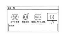
次に、本実施形態の伝送システム1の会議室機能について説明する。会議室機能は、要求元端末と宛先端末との間の参加が制限された第2の通信を、伝送システム1上の仮想的な会議室を使用して行う機能である。まず、会議室の一覧を示す会議室一覧画像について説明する。本実施形態の伝送システム1では、会議室一覧画像は、端末10の機能の一覧を示す機能一覧画像から、会議室アプリケーションをユーザーが選択することにより表示される。図26は、端末の機能一覧を示す画像を示す図である。図27は、会議室一覧を示す画像を示す図である。端末10の操作入力受付部12が、図26の機能一覧画像から会議室アプリケーションを選択する操作入力を受け付けると、端末10の表示制御部16が、図27の会議室一覧画像を表示する。 Next, the conference room function of the transmission system 1 of this embodiment will be described. The conference room function is a function for performing the second communication, in which participation between the request source terminal and the destination terminal is restricted, using a virtual conference room on the transmission system 1. First, a conference room list image showing a list of conference rooms will be described. In the transmission system 1 of the present embodiment, the conference room list image is displayed when the user selects the conference room application from the function list image showing the list of functions of the terminal 10. FIG. 26 is a diagram showing an image showing a list of functions of the terminal. FIG. 27 is a diagram showing an image showing a list of conference rooms. When the operation input reception unit 12 of the terminal 10 receives an operation input for selecting a conference room application from the function list image of FIG. 26, the display control unit 16 of the terminal 10 displays the conference room list image of FIG. 27.

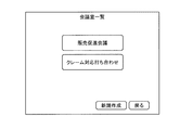
図27の会議室一覧画像は、2つの会議室(販売促進会議及びクレーム対応打ち合わせ)を示す情報を含む場合の例である。また、会議室一覧画像の右下には、新規作成ボタン及び戻るボタンが表示されている。新規作成ボタンは、会議室を新規に作成する場合に、ユーザーが押下するボタンである。戻るボタンは、機能一覧画像の表示に戻る場合に、ユーザーが押下するボタンである。 The meeting room list image in FIG. 27 is an example in the case where information indicating two meeting rooms (sales promotion meeting and complaint correspondence meeting) is included. Also, a new creation button and a return button are displayed at the lower right of the conference room list image. The new creation button is a button that the user presses when creating a new conference room. The return button is a button that the user presses when returning to the display of the function list image.

端末10の操作入力受付部12が、会議室一覧画像の新規作成ボタンの押下を示す操作入力をユーザーから受け付けると、端末10の表示制御部16が、会議室新規作成画像を端末10に表示する。図28は、会議室を新規に作成する時に表示する会議室新規作成画像を示す図である。 When the operation input reception unit 12 of the terminal 10 receives an operation input indicating the pressing of the new creation button for the conference room list image from the user, the display control unit 16 of the terminal 10 displays the newly created conference room image on the terminal 10. .. FIG. 28 is a diagram showing a newly created conference room image displayed when a new conference room is created.

ここで、ユーザーが会議室アプリケーションを選択し、会議室を新規作成する場合の端末10及び管理システム50の処理の流れについて、端末10abのユーザーの場合を例にして説明する。図29は、会議室一覧の表示及び会議室の新規作成時の処理を示したシーケンス図である。 Here, the flow of processing of the terminal 10 and the management system 50 when the user selects a conference room application and newly creates a conference room will be described by taking the case of the user of the terminal 10ab as an example. FIG. 29 is a sequence diagram showing a process of displaying a conference room list and creating a new conference room.

端末10abの操作入力受付部12は、図26の機能一覧画像から会議室アプリケーションを選択する操作入力を受け付ける(ステップS201)。次に、端末10abの送受信部11は、端末10abの端末ID「01ab」を含む会議名一覧取得要求を管理システム50に送信する(ステップS202)。 The operation input receiving unit 12 of the terminal 10ab receives an operation input for selecting a conference room application from the function list image of FIG. 26 (step S201). Next, the transmission/reception unit 11 of the terminal 10ab transmits a conference name list acquisition request including the terminal ID “01ab” of the terminal 10ab to the management system 50 (step S202).

次に、管理システム50の会議管理部58は、送受信部51を介して会議名一覧取得要求を受信する。会議管理部58は、会議室一覧取得要求に含まれる端末10abの端末ID「01ab」に基づいて、端末10abの端末ID「01ab」に関連する会議室の会議室ID及び会議室名を取得する(ステップS203)。具体的には、会議管理部58は、まず、会議室一覧取得要求に含まれる端末10abの端末ID「01ab」を検索キーにして、入室管理DB5007のレコードを検索し、検索されたレコードの会議室ID(1及び3)を取得する。次に、会議管理部58は、会議室管理DB5008を参照して当該会議室ID(1及び3)の会議室名(販売促進会議及びクレーム対応会議)を取得する。 Next, the conference management unit 58 of the management system 50 receives the conference name list acquisition request via the transmission/reception unit 51. The meeting management unit 58 acquires the meeting room ID and the meeting room name of the meeting room related to the terminal ID “01ab” of the terminal 10ab based on the terminal ID “01ab” of the terminal 10ab included in the meeting room list acquisition request. (Step S203). Specifically, the conference management unit 58 first searches for a record in the entry management DB 5007 using the terminal ID “01ab” of the terminal 10ab included in the conference room list acquisition request as a search key, and the conference of the searched record Acquire the room ID (1 and 3). Next, the meeting management unit 58 refers to the meeting room management DB 5008 and acquires the meeting room name (sales promotion meeting and complaint handling meeting) of the meeting room ID (1 and 3).

次に、会議管理部58は、送受信部51を介してステップS203で取得した会議室ID及び会議室名を含む会議室一覧情報を端末10abに送信する(ステップS204)。端末10abの表示制御部16は、送受信部11を介して会議室一覧情報を受信する。端末10abの表示制御部16は、会議室一覧情報の会議室名を含む会議室一覧画像を端末10abに表示する(ステップS205)。 Next, the conference management unit 58 transmits the conference room list information including the conference room ID and the conference room name acquired in step S203 to the terminal 10ab via the transmission/reception unit 51 (step S204). The display control unit 16 of the terminal 10ab receives the conference room list information via the transmission/reception unit 11. The display control unit 16 of the terminal 10ab displays the conference room list image including the conference room name of the conference room list information on the terminal 10ab (step S205).

次に、端末10abの操作入力受付部12は、会議室一覧画像の新規作成ボタンの押下を示す操作入力をユーザーから受け付ける(ステップS206)。端末10abの送受信部11は、端末10abの端末ID「01ab」を含む宛先端末情報取得要求を管理システム50に送信する(ステップS207)。 Next, the operation input reception unit 12 of the terminal 10ab receives an operation input indicating pressing of the new creation button of the conference room list image from the user (step S206). The transmitting/receiving unit 11 of the terminal 10ab transmits a destination terminal information acquisition request including the terminal ID “01ab” of the terminal 10ab to the management system 50 (step S207).

管理システム50の端末抽出部54は、送受信部51を介して宛先端末情報取得要求を受信する。端末抽出部54は、宛先端末情報取得要求に含まれる端末10abの端末ID「01ab」に基づいて、端末10abに関連付けられている宛先端末の宛先端末情報(端末ID、端末名及び稼動状態)を取得する(ステップS208)。具体的には、端末抽出部54は、まず、宛先端末情報取得要求に含まれる端末10abの端末ID「01ab」を検索キーにして、宛先リスト管理DB5004の要求元端末IDを検索し、検索されたレコードの宛先端末ID(「01aa」、「01ca」及び「01cb」)を取得する。次に、端末抽出部54は、当該宛先端末ID(「01aa」、「01ca」及び「01cb」)のそれぞれを検索キーにして、端末管理DB5003の端末IDを検索し、検索されたレコードの端末名及び稼動状態を取得する。例えば、端末抽出部54は、検索キーが「01aa」の場合は、端末名「日本 東京事業所 AA端末」と、稼動状態「ONライン(通話可能)」とを端末管理DB5003のレコードから取得する。 The terminal extraction unit 54 of the management system 50 receives the destination terminal information acquisition request via the transmission/reception unit 51. Based on the terminal ID “01ab” of the terminal 10ab included in the destination terminal information acquisition request, the terminal extraction unit 54 obtains the destination terminal information (terminal ID, terminal name, and operating state) of the destination terminal associated with the terminal 10ab. It is acquired (step S208). Specifically, the terminal extraction unit 54 first searches for the request source terminal ID in the destination list management DB 5004 by using the terminal ID “01ab” of the terminal 10ab included in the destination terminal information acquisition request as a search key. The destination terminal IDs (“01aa”, “01ca”, and “01cb”) of the recorded record are acquired. Next, the terminal extraction unit 54 searches for the terminal ID in the terminal management DB 5003 using each of the destination terminal IDs (“01aa”, “01ca”, and “01cb”) as a search key, and the terminal of the searched record. Get name and operating status. For example, when the search key is “01aa”, the terminal extraction unit 54 acquires the terminal name “Japan Tokyo Office AA terminal” and the operating status “ON line (call enabled)” from the record of the terminal management DB 5003. ..

次に、端末抽出部54は、送受信部51を介してステップS208で取得した端末ID、端末名及び稼動状態を含む宛先端末情報を端末10abに送信する(ステップS209)。端末10abの表示制御部16は、送受信部11を介して宛先端末情報を受信する。表示制御部10abは、宛先端末情報の端末ID、端末名及び稼動状態を含む会議室新規作成画像(図28参照)を端末10abに表示する。端末10abの操作入力受付部12は、会議名、及び会議に参加可能な端末10の選択を示す操作入力を受け付ける(ステップS210)。端末10abの操作入力受付部12は、送受信部11を介して会議名及び会議に参加可能な端末10の端末IDを含む会議室新規作成情報を管理システム50に送信する(ステップS211)。 Next, the terminal extraction unit 54 transmits the destination terminal information including the terminal ID, the terminal name, and the operating status acquired in step S208 to the terminal 10ab via the transmission/reception unit 51 (step S209). The display control unit 16 of the terminal 10ab receives the destination terminal information via the transmission/reception unit 11. The display control unit 10ab displays the newly created conference room image (see FIG. 28) including the terminal ID of the destination terminal information, the terminal name, and the operating state on the terminal 10ab. The operation input reception unit 12 of the terminal 10ab receives an operation input indicating the conference name and the selection of the terminal 10 that can participate in the conference (step S210). The operation input reception unit 12 of the terminal 10ab transmits the conference room new creation information including the conference name and the terminal ID of the terminal 10 capable of participating in the conference to the management system 50 via the transmission/reception unit 11 (step S211).

次に、管理システム50の会議管理部58は、送受信部51を介して会議室新規作成情報を受信する。会議管理部58は、会議室新規作成情報に含まれる会議名に対応する会議室IDを新規に作成する。会議管理部58は、当該会議室IDと当該会議名とを関連付けたレコードを、会議室管理DB5008に作成する。また、会議管理部58は、当該会議室IDと会議室新規作成情報に含まれる端末IDとを関連付けたレコードを、入室管理DB5007に作成する(ステップS212)。 Next, the conference management unit 58 of the management system 50 receives the newly created conference room information via the transmission/reception unit 51. The meeting management unit 58 newly creates a meeting room ID corresponding to the meeting name included in the newly created meeting room information. The conference management unit 58 creates a record in which the conference room ID and the conference name are associated with each other in the conference room management DB 5008. The conference management unit 58 also creates a record in the entry management DB 5007 in which the conference room ID and the terminal ID included in the new conference room creation information are associated with each other (step S212).

会議管理部58は、送受信部51を介して会議室を新規作成したことを示す会議室情報登録通知を端末10abに送信する(ステップS213)。端末10abの表示制御部16は、送受信部11を介して会議室情報登録通知を受信すると、会議室の登録が完了したことを示す情報を含む登録完了画像を端末10abに表示する(ステップS214)。 The conference management unit 58 transmits a conference room information registration notification indicating that a new conference room has been created to the terminal 10ab via the transmission/reception unit 51 (step S213). Upon receiving the conference room information registration notification via the transmitting/receiving unit 11, the display control unit 16 of the terminal 10ab displays a registration completion image including information indicating that the registration of the conference room is completed on the terminal 10ab (step S214). ..

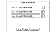
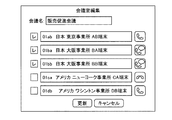
次に、会議室の詳細情報の表示と、会議室情報(会議名及び参加可能な端末10)を編集する場合の端末10と管理システム50の処理の流れについて説明する。まず、会議室の詳細情報を示す会議室詳細画像について説明する。図30は、会議室の詳細情報を示す会議室詳細画像を示す図である。図30の会議室詳細画像は、会議名、参加可能な端末10の情報(端末ID、端末名及び稼動状態)、入室ボタン、編集ボタン及びキャンセルボタンを含む。会議名は、会議室の名称である。参加可能な端末10の情報(端末ID、端末名及び稼動状態)は、当該会議に関連付けられている端末10の情報である。入室ボタンは、当該会議名の会議室を使用して通信を開始するときにユーザーが押下するボタンである。編集ボタンは、当該会議名の会議室の会議室情報(会議名及び参加可能な端末10)を編集するときにユーザーが押下するボタンである。キャンセルボタンは、会議室一覧画像に戻るときにユーザーが押下するボタンである。 Next, a flow of processing of the terminal 10 and the management system 50 when displaying detailed information of the conference room and editing the conference room information (the conference name and the terminal 10 that can participate) will be described. First, a conference room detailed image showing detailed information of the conference room will be described. FIG. 30 is a diagram showing a conference room detailed image showing detailed information of the conference room. The detailed image of the conference room in FIG. 30 includes a conference name, information on the terminals 10 that can participate (terminal ID, terminal name and operating state), a room entry button, an edit button and a cancel button. The meeting name is the name of the meeting room. The information of the terminal 10 that can participate (terminal ID, terminal name, and operating state) is information of the terminal 10 associated with the conference. The room entry button is a button that the user presses when starting communication using the conference room having the conference name. The edit button is a button that the user presses when editing the conference room information (the conference name and the terminals 10 that can participate) of the conference room having the conference name. The cancel button is a button that the user presses when returning to the conference room list image.

端末10の操作入力受付部12が、編集ボタンの押下を受け付けると、端末10の表示制御部16が、会議室編集画像を端末10に表示する。図31は、会議室情報を編集する時に表示する会議室編集画像を示す図である。会議室編集画像は、会議名、参加登録可能な端末10の情報(端末ID、端末名及び稼動状態)、参加登録可能な端末10のうち現在指定されている端末10を示す情報、更新ボタン及びキャンセルボタンを含む。会議名は、会議室の名称である。参加登録可能な端末10の情報(端末ID、端末名及び稼動状態)は、会議室情報を編集する端末10に関連付けられている宛先端末の情報である。参加登録可能な端末10のうち現在指定されている端末10を示す情報は、会議名に対応する会議室IDに関連付けられている端末IDにより特定される端末10を示す情報である。図31の例では、チェックが付いている端末情報が、参加登録可能な端末10のうち現在指定されている端末10を示す情報である。更新ボタンは、編集した会議室情報を確定するときにユーザーが押下するボタンである。キャンセルボタンは、会議室情報の編集をキャンセルし、会議室詳細画像に戻るときにユーザーが押下するボタンである。 When the operation input reception unit 12 of the terminal 10 receives the press of the edit button, the display control unit 16 of the terminal 10 displays the conference room edited image on the terminal 10. FIG. 31 is a diagram showing a conference room edited image displayed when the conference room information is edited. The conference room edited image includes a conference name, information on the terminal 10 that can be registered for participation (terminal ID, terminal name, and operating state), information indicating the currently designated terminal 10 among the terminals 10 that can be registered for participation, an update button, Includes a cancel button. The meeting name is the name of the meeting room. The information (terminal ID, terminal name, and operating status) of the terminal 10 that can be registered for participation is the information of the destination terminal associated with the terminal 10 that edits the conference room information. The information indicating the currently designated terminal 10 among the terminals 10 that can be registered for participation is information indicating the terminal 10 specified by the terminal ID associated with the conference room ID corresponding to the conference name. In the example of FIG. 31, the checked terminal information is information indicating the currently designated terminal 10 among the terminals 10 that can be registered for participation. The update button is a button that the user presses when confirming the edited conference room information. The cancel button is a button that the user presses to cancel the editing of the conference room information and return to the conference room detailed image.

ここで、ユーザーが会議室アプリケーションを選択し、会議室情報を編集する場合の端末10及び管理システム50の処理の流れについて、端末10aaのユーザーの場合を例にして説明する。図32は、会議室一覧の表示及び会議室の編集時の処理を示したシーケンス図である。 Here, the processing flow of the terminal 10 and the management system 50 when the user selects the conference room application and edits the conference room information will be described by taking the case of the user of the terminal 10aa as an example. FIG. 32 is a sequence diagram showing a process of displaying a conference room list and editing a conference room.

ステップS221〜ステップS225については、図29のステップS201〜ステップS205と同様であるため説明を省略する。 Steps S221 to S225 are the same as steps S201 to S205 in FIG. 29, and therefore description thereof will be omitted.

次に、端末10aaの操作入力受付部12は、会議室一覧画像に含まれる販売促進会議の選択を示す操作入力をユーザーから受け付ける(ステップS226)。端末10aaの送受信部11は、販売促進会議の会議室ID「1」を含む宛先端末情報取得要求を管理システム50に送信する(ステップS227)。 Next, the operation input reception unit 12 of the terminal 10aa receives an operation input indicating the selection of the sales promotion conference included in the conference room list image from the user (step S226). The transmission/reception unit 11 of the terminal 10aa transmits the destination terminal information acquisition request including the conference room ID “1” of the sales promotion conference to the management system 50 (step S227).

管理システム50の会議管理部58は、送受信部51を介して宛先端末情報取得要求を受信する。会議管理部58は、宛先端末情報取得要求に含まれる販売促進会議の会議室ID「1」に基づいて、会議室ID「1」に関連付けられている宛先端末の端末ID(「01ab」、「01ba」及び「01bb」)を取得する。次に、端末抽出部54は、当該宛先端末ID(「01ab」、「01ba」及び「01bb」)のそれぞれを検索キーにして、端末管理DB5003の端末IDを検索し、検索されたレコードの端末名及び稼動状態を取得する。例えば、端末抽出部54は、検索キーが「01ab」の場合は、端末名「日本 東京事業所 AB端末」と、稼動状態「OFFライン」とを端末管理DB5003のレコードから取得する(ステップS228)。 The conference management unit 58 of the management system 50 receives the destination terminal information acquisition request via the transmission/reception unit 51. The conference managing unit 58, based on the conference room ID “1” of the sales promotion conference included in the destination terminal information acquisition request, the terminal IDs (“01ab” and “01ab” of the destination terminals associated with the conference room ID “1”. 01ba” and “01bb”). Next, the terminal extraction unit 54 searches for the terminal ID in the terminal management DB 5003 using each of the destination terminal IDs (“01ab”, “01ba”, and “01bb”) as a search key, and the terminal of the searched record. Get name and operating status. For example, when the search key is “01ab”, the terminal extraction unit 54 acquires the terminal name “Japan Tokyo Office AB terminal” and the operating status “OFF line” from the record of the terminal management DB 5003 (step S228). ..

次に、端末抽出部54は、送受信部51を介してステップS228で取得した端末ID、端末名及び稼動状態を含む宛先端末情報を端末10aaに送信する(ステップS229)。端末10aaの表示制御部16は、送受信部11を介して宛先端末情報を受信する。表示制御部16は、宛先端末情報の端末ID、端末名及び稼動状態を含む会議室詳細画像(図30参照)を端末10aaに表示する(ステップS230)。次に、端末10aaの操作入力受付部12は、編集ボタンの押下を受け付ける(ステップS231)。次に、端末10aaの送受信部51は、端末10aaの端末ID「01aa」を含む編集候補宛先端末情報取得要求を管理システム50に送信する(ステップS232)。 Next, the terminal extraction unit 54 transmits the destination terminal information including the terminal ID, the terminal name, and the operating status acquired in step S228 to the terminal 10aa via the transmission/reception unit 51 (step S229). The display control unit 16 of the terminal 10aa receives the destination terminal information via the transmission/reception unit 11. The display control unit 16 displays the conference room detailed image (see FIG. 30) including the terminal ID of the destination terminal information, the terminal name, and the operating state on the terminal 10aa (step S230). Next, the operation input reception unit 12 of the terminal 10aa receives the press of the edit button (step S231). Next, the transmission/reception unit 51 of the terminal 10aa transmits an edit candidate destination terminal information acquisition request including the terminal ID “01aa” of the terminal 10aa to the management system 50 (step S232).

管理システム50の端末抽出部54は、送受信部51を介して編集候補宛先端末情報取得要求を受信する。端末抽出部54は、編集候補宛先端末情報取得要求に含まれる端末10aaの端末ID「01aa」に基づいて、端末10aaに関連付けられている宛先端末の宛先端末情報(端末ID、端末名及び稼動状態)を取得する(ステップS233)。具体的には、端末抽出部54は、まず、編集宛先端末情報取得要求に含まれる端末10aaの端末ID「01aa」を検索キーにして、宛先リスト管理DB5004の要求元端末IDを検索し、検索されたレコードの宛先端末ID(「01ab」、「01ba」、「01bb」、「01ca」及び「01db」)を取得する。次に、端末抽出部54は、当該宛先端末ID(「01ab」、「01ba」、「01bb」、「01ca」及び「01db」)のそれぞれを検索キーにして、端末管理DB5003の端末IDを検索し、検索されたレコードの端末名及び稼動状態を取得する。例えば、端末抽出部54は、検索キーが「01ab」の場合は、端末名「日本 東京事業所 AB端末」と、稼動状態「OFFライン」とを端末管理DB5003のレコードから取得する。 The terminal extraction unit 54 of the management system 50 receives the edit candidate destination terminal information acquisition request via the transmission/reception unit 51. The terminal extraction unit 54, based on the terminal ID “01aa” of the terminal 10aa included in the edit candidate destination terminal information acquisition request, the destination terminal information (terminal ID, terminal name, and operating state) of the destination terminal associated with the terminal 10aa. ) Is acquired (step S233). Specifically, the terminal extracting unit 54 first searches for the request source terminal ID in the destination list management DB 5004 using the terminal ID “01aa” of the terminal 10aa included in the edit destination terminal information acquisition request as a search key, and then searches. The destination terminal ID (“01ab”, “01ba”, “01bb”, “01ca”, and “01db”) of the recorded record is acquired. Next, the terminal extraction unit 54 searches for the terminal ID in the terminal management DB 5003 using each of the destination terminal IDs (“01ab”, “01ba”, “01bb”, “01ca”, and “01db”) as a search key. Then, the terminal name and the operating status of the retrieved record are acquired. For example, when the search key is “01ab”, the terminal extraction unit 54 acquires the terminal name “Japan Tokyo Office AB terminal” and the operating state “OFF line” from the record of the terminal management DB 5003.

次に、端末抽出部54は、送受信部51を介してステップS233で取得した端末ID、端末名及び稼動状態を含む編集候補宛先端末情報(宛先端末状態情報)を端末10aaに送信する(ステップS234)。端末10aaの表示制御部16は、送受信部11を介して編集候補宛先端末情報を受信すると、編集候補宛先端末情報を含む販売促進会議の会議室編集画像(図31参照)を端末10aaに表示する(ステップS235)。図31の会議室編集画像において、チェックの付いている宛先端末情報が、現在指定されている宛先端末の宛先端末情報であり、チェックの付いていない宛先端末情報が、端末10aaが指定可能な宛先端末の宛先端末情報である。 Next, the terminal extraction unit 54 transmits the edit candidate destination terminal information (destination terminal state information) including the terminal ID, the terminal name, and the operating state acquired in step S233 to the terminal 10aa via the transmission/reception unit 51 (step S234). ). Upon receiving the editing candidate destination terminal information via the transmitting/receiving unit 11, the display control unit 16 of the terminal 10aa displays the conference room edited image (see FIG. 31) of the sales promotion conference including the editing candidate destination terminal information on the terminal 10aa. (Step S235). In the edited image of the conference room in FIG. 31, the checked destination terminal information is the destination terminal information of the currently designated destination terminal, and the unchecked destination terminal information is the destination that can be designated by the terminal 10aa. This is destination terminal information of the terminal.

端末10aaの操作入力受付部12は、販売促進会議の会議室情報(会議名及び参加可能な端末10)の編集に係る操作入力を受け付ける(ステップS236)。端末10aaの操作入力受付部12が更新ボタンの押下を受け付けると、送受信部11は、会議室ID、会議名、端末ID、並びに当該端末IDの追加又は削除を示す情報を含む会議室編集情報を管理システム50に送信する(ステップS237)。 The operation input reception unit 12 of the terminal 10aa receives an operation input related to the editing of the conference room information (the conference name and the terminal 10 that can participate) of the sales promotion conference (step S236). When the operation input reception unit 12 of the terminal 10aa receives the press of the update button, the transmission/reception unit 11 displays the conference room editing information including the conference room ID, the conference name, the terminal ID, and information indicating addition or deletion of the terminal ID. It transmits to the management system 50 (step S237).

次に、管理システム50の会議管理部58は、送受信部51を介して会議室編集情報を受信する。会議管理部58は、会議室編集情報に含まれる会議室IDと端末IDとの組み合わせについて、当該端末IDの追加又は削除を示す情報に応じて、入室管理DB5007のレコードの追加又は削除を行う。また、会議管理部58は、会議室編集情報に含まれる会議室IDを検索キーにして、会議室管理DB5008の会議室IDを検索し、検索されたレコードの会議名を会議室編集情報に含まれる会議名により更新する(ステップS238)。 Next, the conference management unit 58 of the management system 50 receives the conference room editing information via the transmission/reception unit 51. The meeting management unit 58 adds or deletes the record of the entry management DB 5007 for the combination of the meeting room ID and the terminal ID included in the meeting room editing information according to the information indicating the addition or deletion of the terminal ID. Further, the conference management unit 58 searches for the conference room ID in the conference room management DB 5008 using the conference room ID included in the conference room editing information as a search key, and includes the conference name of the retrieved record in the conference room editing information. The conference name is updated (step S238).

会議管理部58は、送受信部51を介して会議室情報の更新が終了したことを示す会議室情報更新通知を端末10aaに送信する(ステップS239)。端末10aaの表示制御部16は、送受信部11を介して会議室情報更新通知を受信すると、会議室の更新が完了したことを示す情報を含む更新完了画像を端末10aaに表示する(ステップS240)。 The conference management unit 58 transmits a conference room information update notification indicating that the update of the conference room information has been completed to the terminal 10aa via the transmission/reception unit 51 (step S239). Upon receiving the conference room information update notification via the transmission/reception unit 11, the display control unit 16 of the terminal 10aa displays an update completion image including information indicating that the update of the conference room is completed on the terminal 10aa (step S240). ..

次に、会議室を使用した通信を開始する場合の端末10及び管理システム50の処理について説明する。まず、会議室一覧画像から会議名を選択して会議室に入室する(当該会議名の会議室を使用して通信を開始する)場合について説明する。 Next, processing of the terminal 10 and the management system 50 when starting communication using the conference room will be described. First, a case will be described in which a conference name is selected from the conference room list image to enter the conference room (communication is started using the conference room having the conference name).

図33は、会議室一覧から、会議室に入室する時の処理を示したシーケンス図である。ステップS241〜ステップS250は、図32のステップS221〜ステップS230と同じであるため説明を省略する。 FIG. 33 is a sequence diagram showing processing when entering a conference room from the conference room list. Since steps S241 to S250 are the same as steps S221 to S230 of FIG. 32, description thereof will be omitted.

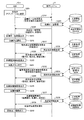
端末10(要求元端末)の操作入力受付部12は、会議室詳細画像(図30参照)の入室ボタンの押下を示す操作入力を受け付ける(ステップS251)。次に、端末10の送受信部11は、入室ボタンを押下した要求元端末の端末IDと、第2の通信による通話の開始を要求する旨を示す情報「Invite+Room」と、当該会議室の会議室IDとを含む入室要求を管理システム50に送信する(ステップS252)。管理システム50の会議管理部58は、送受信部51を介して入室要求を受信する。会議管理部58は、入室要求に含まれる会議室IDと端末IDとの組み合わせと一致するレコードが、入室管理DB5007にあるか否かを判定する(ステップS253)。 The operation input reception unit 12 of the terminal 10 (request source terminal) receives an operation input indicating pressing of the entry button of the conference room detailed image (see FIG. 30) (step S251). Next, the transmission/reception unit 11 of the terminal 10 transmits the terminal ID of the request source terminal that has pressed the room entry button, the information “Invite+Room” indicating that the call of the second communication is requested, and the conference room of the conference room. An entry request including the ID is transmitted to the management system 50 (step S252). The conference management unit 58 of the management system 50 receives the entry request via the transmission/reception unit 51. The meeting management unit 58 determines whether or not the record matching the combination of the meeting room ID and the terminal ID included in the entry request is in the entry management DB 5007 (step S253).

会議管理部58は、ステップS253の判定結果に応じた処理を行う(ステップS254)。図34は、入室判定の結果に応じた処理を示すフローチャートである。 The conference management unit 58 performs processing according to the determination result of step S253 (step S254). FIG. 34 is a flowchart showing the processing according to the result of the entry determination.

入室要求に含まれる会議室IDと端末IDとの組み合わせと一致するレコードが、入室管理DB5007になく、管理システム50の判定部59の入室判定の結果が、入室OKでない場合(ステップS254−1、No)、送受信部51は、入室不可を示すエラー情報を、入室要求を送信した要求元端末に送信する(ステップS254−7)。 When there is no record in the entry management DB 5007 that matches the combination of the conference room ID and the terminal ID included in the entry request, and the entry determination result of the determination unit 59 of the management system 50 is not entry OK (step S254-1, No), the transmission/reception unit 51 transmits error information indicating that entry is not possible to the request source terminal that has transmitted the entry request (step S254-7).

入室要求に含まれる会議室IDと端末IDとの組み合わせと一致するレコードが、入室管理DB5007にあり、管理システム50の判定部59の入室判定の結果が、入室OKである場合(ステップS254−1、Yes)、ステップS254−2の処理に進む。 When the record that matches the combination of the conference room ID and the terminal ID included in the entry request is in the entry management DB 5007 and the entry determination result of the determination unit 59 of the management system 50 is entry OK (step S254-1). , Yes), and proceeds to the processing of step S254-2.

セッション管理部57は、入室要求に含まれる会議室IDにより特定される会議室を使用した通信が既に行われているか否か(セッションが既に確立しているか否か)を判定する(ステップS254−2)。具体的には、セッション管理部57は、入室要求に含まれる会議室IDを検索キーにして、会議室管理DB5008を検索し、検索されたレコードのセッションIDフィールドに、セッションIDが設定されているか否かを判定する。すなわち、セッション管理部57は、検索されたレコードのセッションIDフィールドに、セッションIDが設定されている場合、セッションが既に確立していることを判定する。 The session management unit 57 determines whether or not communication using the conference room specified by the conference room ID included in the entry request has already been performed (whether or not the session has already been established) (step S254-). 2). Specifically, the session management unit 57 searches the conference room management DB 5008 by using the conference room ID included in the entry request as a search key, and whether the session ID is set in the session ID field of the retrieved record. Determine whether or not. That is, the session management unit 57 determines that the session has already been established when the session ID is set in the session ID field of the retrieved record.

セッションが既に確立している場合(ステップS254−2、Yes)、当該セッションIDを検索キーにして、セッション管理DB5005を検索し、検索されたレコードの宛先端末IDフィールドに、入室要求に含まれる要求元端末の端末IDを追加し(ステップS254−3)、ステップS254−6に進む。 When the session has already been established (step S254-2, Yes), the session management DB 5005 is searched using the session ID as a search key, and the request included in the entry request is included in the destination terminal ID field of the searched record. The terminal ID of the original terminal is added (step S254-3), and the process proceeds to step S254-6.

セッションがまだ確立していない場合(ステップS254−2、No)、セッション管理部57は、セッションIDを新規に作成し、セッション管理DB5005にレコードを新規に作成する(ステップS254−4)。なお、セッションIDの新規作成に係る具体的な処理については、図20のステップS43〜ステップS45と同様であるが、ステップS45において、宛先端末IDフィールドに、要求元端末IDフィールドの値と同じ値を設定する点が異なる。 When the session has not been established yet (step S254-2, No), the session management unit 57 newly creates a session ID and a new record in the session management DB 5005 (step S254-4). The specific process related to the new creation of the session ID is the same as steps S43 to S45 in FIG. 20, but in step S45, the destination terminal ID field has the same value as the request source terminal ID field. The difference is that you set.

次に、会議管理部58は、入室要求に含まれる会議室IDを検索キーにして、会議室管理DB5008を検索し、検索されたレコードのセッションIDフィールドに、ステップS254−4で新規に作成したセッションIDを設定する(ステップS254−5)。 Next, the meeting management unit 58 searches the meeting room management DB 5008 using the meeting room ID included in the entry request as a search key, and newly creates it in the session ID field of the searched record in step S254-4. A session ID is set (step S254-5).

次に、送受信部51は、セッションIDと中継装置接続情報(中継装置30のIPアドレス、認証情報、及びポート番号等)とを入室要求を送信した要求元端末に送信する(ステップS254−6)。以上の処理により、要求元端末が中継装置と接続する処理が終了する。次に、要求元端末が、中継要求情報を管理システム50に送信し、通話データの中継を要求する処理(図23、ステップS61−1〜ステップS65−1参照)を開始する。これにより、会議室一覧に含まれる会議名の選択をユーザーから受け付けることにより入室要求を送信した要求元端末が、当該会議室を使用した通信を開始する。 Next, the transmission/reception unit 51 transmits the session ID and the relay device connection information (IP address, authentication information, port number, etc. of the relay device 30) to the request source terminal that transmitted the entry request (step S254-6). .. Through the above processing, the processing for connecting the request source terminal to the relay device is completed. Next, the request source terminal transmits the relay request information to the management system 50 and starts the process of requesting the relay of the call data (see step S61-1 to step S65-1 in FIG. 23). As a result, the request source terminal that has transmitted the entry request by accepting the selection of the conference name included in the conference room list from the user starts communication using the conference room.

次に、宛先端末一覧画像(図18参照)から宛先端末を選択して会議室に入室する(当該会議名の会議室を使用して通信を開始する)場合について説明する。 Next, a case will be described in which a destination terminal is selected from the destination terminal list image (see FIG. 18) to enter the conference room (communication is started using the conference room having the conference name).

まず、宛先端末一覧画像の宛先端末一覧情報から、稼動状態が「ONライン(通話中)」であり、かつ、会議室アイコン(図18、画像1504参照)が表示されている宛先端末情報の選択を受け付けた場合について説明する。 First, from the destination terminal list information of the destination terminal list image, selection of destination terminal information in which the operating state is “ON line (call in progress)” and the conference room icon (see image 1504 in FIG. 18) is displayed The case of accepting will be described.

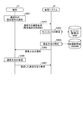
図35は、宛先一覧から、ONライン(通話中)の宛先端末を選択して通信を開始する時の処理を示したシーケンス図である。端末10の操作入力受付部12は、宛先端末一覧画像に示された宛先端末一覧情報から、稼動状態が「ONライン(通話中)」であり、かつ、会議室アイコン(図18、画像1504参照)が表示されている宛先端末情報の選択を受け付ける(ステップS261)。 FIG. 35 is a sequence diagram showing a process for selecting a destination terminal on the ON line (during a call) from the destination list and starting communication. From the destination terminal list information shown in the destination terminal list image, the operation input reception unit 12 of the terminal 10 has the operating state of “ON line (during a call)” and the conference room icon (see FIG. 18, image 1504). The selection of the destination terminal information for which () is displayed is accepted (step S261).

次に、送受信部11は、選択された宛先端末の端末IDを含む通信方法確認要求を管理システム50に送信する(ステップS262)。管理システム50のセッション管理部57は、送受信部51を介して通信方法確認要求を受信する。セッション管理部57は、通信方法確認要求に含まれる端末IDを検索キーにして、セッション管理DB5005の要求元端末IDフィールド及び宛先端末IDフィールドを検索し、検索されたレコードからセッションIDを特定する(ステップS263)。 Next, the transmission/reception unit 11 transmits a communication method confirmation request including the terminal ID of the selected destination terminal to the management system 50 (step S262). The session management unit 57 of the management system 50 receives the communication method confirmation request via the transmission/reception unit 51. The session management unit 57 uses the terminal ID included in the communication method confirmation request as a search key to search the request source terminal ID field and the destination terminal ID field of the session management DB 5005, and specifies the session ID from the searched record ( Step S263).

次に、会議管理部58は、当該セッションIDを検索キーにして、会議室管理DB5008のセッションIDフィールドを検索し、当該セッションIDが設定されているレコードがあるか否かを判定することにより、通信方法を特定する(ステップS264)。すなわち、会議管理部58は、当該セッションIDが設定されているレコードがある場合、当該セッションIDにより特定される通信が、会議室を使用した第2の通信であることを特定する。 Next, the conference management unit 58 searches the session ID field of the conference room management DB 5008 using the session ID as a search key, and determines whether or not there is a record in which the session ID is set. The communication method is specified (step S264). That is, when there is a record in which the session ID is set, the conference management unit 58 identifies that the communication identified by the session ID is the second communication using the conference room.

送受信部51は、ステップS264で特定された通信方法を示す情報を含む通知を端末10に送信する(ステップS265)。次に、端末10の送受信部11は、通信方法の通知を管理システム50から受信する(ステップS266)と、送受信部11は、当該通知に応じて発信を行う(ステップS267)。すなわち、送受信部11は、通常発信による開始要求情報、又は入室発信による開始要求情報を管理システム50に送信する。通常発信による開始要求情報は、要求元端末を識別するための端末ID、宛先端末を識別するための端末ID、及び第1の通信による通話の開始を要求する旨を示す情報「Invite」を含む。入室発信による開始要求情報は、要求元端末を識別するための端末ID、宛先端末を識別するための端末ID、及び第2の通信による通話の開始を要求する旨を示す情報「Invite+Room」を含む。 The transmission/reception unit 51 transmits a notification including information indicating the communication method specified in step S264 to the terminal 10 (step S265). Next, when the transmission/reception unit 11 of the terminal 10 receives the notification of the communication method from the management system 50 (step S266), the transmission/reception unit 11 performs transmission according to the notification (step S267). That is, the transmission/reception unit 11 transmits the start request information by the normal call or the start request information by the entry call to the management system 50. The normal call start request information includes a terminal ID for identifying the request source terminal, a terminal ID for identifying the destination terminal, and information “Invite” indicating that the call start by the first communication is requested. .. The start request information for entering the room includes a terminal ID for identifying the request source terminal, a terminal ID for identifying the destination terminal, and information “Invite+Room” indicating that a call start by the second communication is requested. ..

次に、宛先端末一覧画像の宛先端末一覧情報から、稼動状態が「ONライン(通話可能)」であり、かつ、会議室アイコン(図18、画像1504参照)が表示されている宛先端末情報の選択を受け付けた場合について説明する。 Next, from the destination terminal list information of the destination terminal list image, the destination terminal information whose operating state is “ON line (communication possible)” and the conference room icon (see image 1504 in FIG. 18) is displayed. The case where the selection is accepted will be described.

図36は、宛先一覧から、ONライン(通話可能)の宛先端末を選択して会議室に入室する時の処理を示したフローチャートである。端末10の操作入力受付部12は、宛先端末一覧画像に示された宛先端末一覧情報から、稼動状態が「ONライン(通話可能)」であり、かつ、会議室アイコン(図18、画像1504参照)が表示されている宛先端末情報の選択を受け付ける(ステップS271)。次に、端末10の表示制御部16は、会議室を使用する参加の制限された通信方法による発信(入室発信)、又は会議室を使用しない発信(通常発信)をユーザーが選択するための画像を表示する(ステップS272)。 FIG. 36 is a flowchart showing a process when selecting an ON-line (callable) destination terminal from the destination list and entering the conference room. From the destination terminal list information shown in the destination terminal list image, the operation input reception unit 12 of the terminal 10 has the operating state of “ON line (communication possible)” and the conference room icon (see FIG. 18, image 1504). ) Is accepted to select the destination terminal information (step S271). Next, the display control unit 16 of the terminal 10 displays an image for the user to select whether to use the conference room to make a call (entry call) or a call that does not use the meeting room (normal call). Is displayed (step S272).

操作入力受付部12は、通信方法の選択を示す操作入力をユーザーから受け付けることにより通信(発信)方法を特定する(ステップS273)。 The operation input reception unit 12 specifies the communication (transmission) method by receiving the operation input indicating the selection of the communication method from the user (step S273).

通信方法が会議室を使用した通信である場合(ステップS273、会議室使用)、送受信部11は、要求元端末の端末ID、第2の通信による通話の開始を要求する旨を示す情報「Invite+Room」、及び通信に使用する会議室を識別するための情報を含む入室発信による開始要求情報を送信する(ステップS274)。なお、通信に使用する会議室を識別するための情報は、会議室ID又は宛先端末の端末IDである。宛先端末の端末IDの場合は、管理システム50の会議管理部58が、宛先端末の端末IDを検索キーにして、入室管理DB5007の端末IDを検索し、検索されたレコードの会議室IDを取得することにより通信に使用する会議室を特定する。 When the communication method is the communication using the conference room (step S273, use of the conference room), the transmission/reception unit 11 notifies the terminal ID of the request source terminal and the information “Invite+Room” indicating that the start of the call by the second communication is requested. ], and start request information by entry call transmission including information for identifying a conference room used for communication (step S274). The information for identifying the conference room used for communication is the conference room ID or the terminal ID of the destination terminal. In the case of the terminal ID of the destination terminal, the conference management unit 58 of the management system 50 uses the terminal ID of the destination terminal as a search key to search for the terminal ID in the entry management DB 5007, and acquires the conference room ID of the searched record. By doing so, the conference room used for communication is specified.

通信方法が会議室を使用した通信でない場合(ステップS273、通常)、送受信部11は、要求元端末の端末ID及び宛先端末の端末IDを含む通常発信による開始要求情報を送信する(ステップS275)。 When the communication method is not the communication using the conference room (step S273, normal), the transmission/reception unit 11 transmits start request information by normal transmission including the terminal ID of the request source terminal and the terminal ID of the destination terminal (step S275). ..

ここで、管理システム50側の開始要求情報の受信処理について説明する。通常発信による開始要求情報の場合は、図20(通信の開始を要求する処理)、図21(通信の開始の要求を許可する処理)及び図22(通信の開始の要求を拒否する処理)で説明したため省略する。 Here, the reception processing of the start request information on the management system 50 side will be described. In the case of start request information by normal transmission, in FIG. 20 (process for requesting start of communication), FIG. 21 (process for permitting request for start of communication) and FIG. 22 (process for rejecting request for start of communication). Since it is explained, it is omitted.

入室発信による開始要求情報の場合について説明する。入室発信の開始要求情報は、要求元端末の端末ID及び入室する会議室を特定するための情報(会議室ID又は宛先端末の端末ID)を含む。 The case of the start request information by calling into the room will be described. The entry request information for entering the room includes the terminal ID of the request source terminal and the information for identifying the meeting room to enter (the meeting room ID or the terminal ID of the destination terminal).

まず、入室する会議室を特定するための情報が、会議室IDである場合について説明する。管理システム50の判定部59は、送受信部51を介して入室発信の開始要求情報を受信したときに、開始要求情報に含まれる会議室IDに、開始要求情報に含まれる要求元端末の端末IDが関連付けられているか否かを判定する。セッション管理部57は、関連付けられている場合、当該会議室IDにより識別される第2の通信の開始を許可する。具体的には、セッション管理部57は、当該会議室IDにより識別される第2の通信を開始するためのセッションの生成に係るセッション管理処理(図34のステップS254−4〜ステップS254−6参照)を行う。 First, a case where the information for identifying the conference room to enter is the conference room ID will be described. When the determination unit 59 of the management system 50 receives the entry request start request information via the transmission/reception unit 51, the conference room ID included in the start request information and the terminal ID of the request source terminal included in the start request information are received. Is associated with. When associated, the session management unit 57 permits the start of the second communication identified by the conference room ID. Specifically, the session management unit 57 performs the session management process related to the generation of the session for starting the second communication identified by the conference room ID (see step S254-4 to step S254-6 in FIG. 34). )I do.

次に、入室する会議室を特定するための情報が、宛先端末の端末IDである場合について説明する。管理システム50の判定部59は、送受信部51を介して入室発信の開始要求情報を受信したときに、開始要求情報に含まれる宛先端末の端末IDに関連付けられた会議室IDを特定し、特定された会議室IDに開始要求情報に含まれる要求元端末の端末IDが関連付けられているか否かを判定する。セッション管理部57は、関連付けられている場合、当該会議室IDにより識別される第2の通信の開始を許可する。具体的には、セッション管理部57は、当該会議室IDにより識別される第2の通信を開始するためのセッションの生成に係るセッション管理処理(図34のステップS254−4〜ステップS254−6参照)を行う。 Next, a case where the information for identifying the conference room to enter is the terminal ID of the destination terminal will be described. When the determination unit 59 of the management system 50 receives the entry request information for entering the room via the transmission/reception unit 51, the determination unit 59 identifies the meeting room ID associated with the terminal ID of the destination terminal included in the entry request information, and specifies the conference room ID. It is determined whether the conference room ID is associated with the terminal ID of the request source terminal included in the start request information. When associated, the session management unit 57 permits the start of the second communication identified by the conference room ID. Specifically, the session management unit 57 performs the session management process related to the generation of the session for starting the second communication identified by the conference room ID (see step S254-4 to step S254-6 in FIG. 34). )I do.

なお、宛先端末側の処理は、入室発信による開始要求情報の場合についても、図21(通信の開始の要求を許可する処理)及び図22(通信の開始の要求を拒否する処理)と同様であるため、説明を省略する。 Note that the processing on the destination terminal side is the same as in FIG. 21 (processing for permitting a request to start communication) and FIG. 22 (processing for rejecting a request to start communication), even in the case of start request information due to entry into a room. Therefore, the description is omitted.

図36に戻り、送受信部11は、宛先端末と通信可能であるか否かを示す開始応答情報を管理システム50から受信する(ステップS276)。送受信部11は、開始応答情報を参照して宛先端末と通信可能であるか否かを判定する(ステップS277)。通信可能である場合(ステップS277、Yes)、送受信部11は、宛先端末との通信を開始する(ステップS278)。通信可能でない場合(ステップS277、No)、表示制御部16は、宛先端末と通信ができない理由を示すエラー情報を端末10に表示する(ステップS279)。 Returning to FIG. 36, the transmission/reception unit 11 receives start response information indicating whether communication with the destination terminal is possible from the management system 50 (step S276). The transmission/reception unit 11 refers to the start response information and determines whether or not communication with the destination terminal is possible (step S277). When communication is possible (step S277, Yes), the transmission/reception unit 11 starts communication with the destination terminal (step S278). When communication is not possible (No in step S277), the display control unit 16 displays error information indicating the reason why communication with the destination terminal is not possible on the terminal 10 (step S279).

ここで、図36の説明において、入室発信の開始要求情報の入室する会議室を特定するための情報が、宛先端末の端末IDである場合について補足する。判定部59が、送受信部51を介して入室発信の開始要求情報を受信したときに、開始要求情報に含まれる要求元端末の端末IDが、複数の会議室IDと関連付けられている場合がある。このときは、判定部59は、送受信部51を介して、会議室IDにより識別される会議を示す情報(会議名など)を複数含む会議一覧情報を要求元端末に送信し、送受信部51が、会議一覧情報から選択された一の会議を示す情報を更に受信することにより、要求元端末が入室する一の会議室を特定する。 Here, in the description of FIG. 36, the case where the information for specifying the conference room to be entered in the entry request start information is the terminal ID of the destination terminal will be supplemented. When the determination unit 59 receives the entrance request start request information via the transmission/reception unit 51, the terminal ID of the request source terminal included in the start request information may be associated with a plurality of conference room IDs. .. At this time, the determination unit 59 transmits, via the transmission/reception unit 51, the conference list information including a plurality of pieces of information (conference name etc.) indicating the conference identified by the conference room ID to the request source terminal, and the transmission/reception unit 51 By further receiving the information indicating the one conference selected from the conference list information, the one conference room into which the request source terminal enters is specified.

以上説明したように本実施形態によれば、管理システム50は、宛先端末と、当該宛先端末に、仮想的な会議室を使用して行われる第2の通信が関連付けられているか否かを示す情報とを含む宛先端末状態情報を一以上含む宛先端末状態一覧情報を、端末10に送信する。これにより、端末10のユーザーは、会議名などの情報を指定しなくても、当該仮想的な会議室を使用した第2の通信を、当該宛先端末のユーザーと行うことができる。 As described above, according to the present embodiment, the management system 50 indicates whether or not the destination terminal is associated with the second communication performed using the virtual conference room. The destination terminal state list information including at least one destination terminal state information including the information is transmitted to the terminal 10. Accordingly, the user of the terminal 10 can perform the second communication using the virtual conference room with the user of the destination terminal without specifying the information such as the conference name.

また、本実施形態によれば、宛先端末状態情報は、宛先端末の稼動状態情報を含むため、端末10のユーザーは、端末10に表示された宛先端末状態一覧情報を示す画像から、宛先端末の稼動状態を参照しながら通信を開始するか否かを判断することができる。 Further, according to the present embodiment, since the destination terminal status information includes the operating status information of the destination terminal, the user of the terminal 10 can determine the destination terminal status information from the image showing the destination terminal status list information displayed on the terminal 10. It is possible to determine whether or not to start communication while referring to the operating state.

<<実施形態の補足>> <<Supplement to Embodiment>>

また、上記各実施形態における管理システム50、及びプログラム提供システム90は、単一のコンピュータによって構築されてもよいし、各部(機能又は手段)を分割して任意に割り当てられた複数のコンピュータによって構築されていてもよい。また、プログラム提供システム90が単一のコンピュータによって構築されている場合には、プログラム提供システム90によって送信されるプログラムは、複数のモジュールに分けて送信されるようにしてもよいし、分けないで送信されるようにしてもよい。更に、プログラム提供システム90が複数のコンピュータによって構築されている場合には、複数のモジュールが分けられた状態で、各コンピュータから送信されるようにしてもよい。 Further, the management system 50 and the program providing system 90 in each of the above embodiments may be constructed by a single computer, or may be constructed by a plurality of computers in which each unit (function or means) is divided and arbitrarily assigned. It may have been done. When the program providing system 90 is constructed by a single computer, the program transmitted by the program providing system 90 may be divided into a plurality of modules and may be transmitted. It may be transmitted. Further, when the program providing system 90 is constructed by a plurality of computers, a plurality of modules may be divided and transmitted from each computer.

また、上記本実施形態の端末用プログラム、中継装置用プログラム、及び伝送管理用プログラムが記憶された記録媒体、並びに、これらプログラムが記憶されたHD204、及びこのHD204を備えたプログラム提供システム90は、いずれもプログラム製品(Program Product)として、国内又は国外へ、上記端末用プログラム、中継装置用プログラム、及び伝送管理用プログラムが利用者等に提供される場合に用いられる。 Further, the recording medium in which the terminal program, the relay device program, and the transmission management program of the present embodiment are stored, the HD 204 in which these programs are stored, and the program providing system 90 including this HD 204 are Both are used as program products when the terminal program, the relay device program, and the transmission management program are provided domestically or internationally to a user or the like.

更に、上記実施形態では、図8で中継装置のIPアドレス、図10で端末のIPアドレスを管理することとしたが、これに限るものではなく、通信ネットワーク2上で中継装置30を特定するための中継装置特定情報、又は通信ネットワーク2上で端末10を特定するための端末特定情報であれば、それぞれのFQDN(Fully Qualified Domain Name)を管理してもよい。この場合、周知のDNS(Domain Name System)サーバによって、FQDNに対応するIPアドレスが取得されることになる。なお、「通信ネットワーク2で中継装置30を特定するための中継装置特定情報」だけでなく、「通信ネットワーク2上における中継装置30への接続先を示した中継装置接続先情報」、又は「通信ネットワーク2上における中継装置30への宛先を示した中継装置宛先情報」と表現してもよい。同じく、「通信ネットワーク2で端末10を特定するための端末特定情報」だけでなく、「通信ネットワーク2上における端末10への接続先を示した端末接続先情報」、又は「通信ネットワーク2上における端末10への宛先を示した端末宛先情報」と表現してもよい。 Further, in the above embodiment, the IP address of the relay device is managed in FIG. 8 and the IP address of the terminal is managed in FIG. 10, but the invention is not limited to this, and the relay device 30 is specified on the communication network 2. The FQDN (Fully Qualified Domain Name) may be managed as long as it is the relay device specifying information of 1. or the terminal specifying information for specifying the terminal 10 on the communication network 2. In this case, the well-known DNS (Domain Name System) server acquires the IP address corresponding to the FQDN. Note that not only "relay device identification information for identifying the relay device 30 in the communication network 2" but also "relay device connection destination information indicating a connection destination to the relay device 30 on the communication network 2" or "communication It may be expressed as “relay device destination information indicating a destination to the relay device 30 on the network 2.” Similarly, not only “terminal identification information for identifying the terminal 10 on the communication network 2” but also “terminal connection destination information indicating a connection destination to the terminal 10 on the communication network 2” or “on the communication network 2” It may also be expressed as "terminal destination information indicating the destination to the terminal 10."

本実施形態において、「テレビ会議」は、「ビデオ会議」と置き換え可能な用語として用いられている。 In the present embodiment, “video conference” is used as a term that can be replaced with “video conference”.

また、上記実施形態では、伝送システム1の一例として、テレビ会議システムの場合について説明したが、これに限るものではなく、IP(Internet Protocol)電話や、インターネット電話等の電話システムであってもよい。また、伝送システム1は、カーナビゲーションシステムであってもよい。この場合、例えば、端末10の一方が自動車に搭載されたカーナビゲーション装置に相当し、端末10の他方が、カーナビゲーションを管理する管理センターの管理端末若しくは管理サーバ、又は他の自動車に搭載されているカーナビゲーション装置に相当する。更に、伝送システム1は、音声会議システム、又はPC(Personal Computer)画面共有システムであっても良い。 Further, in the above-described embodiment, the case of the video conference system has been described as an example of the transmission system 1, but the present invention is not limited to this, and a telephone system such as an IP (Internet Protocol) telephone or an internet telephone may be used. .. Further, the transmission system 1 may be a car navigation system. In this case, for example, one of the terminals 10 corresponds to a car navigation device installed in a car, and the other of the terminals 10 is installed in a management terminal or a management server of a management center that manages car navigation, or in another car. It corresponds to the existing car navigation system. Furthermore, the transmission system 1 may be a voice conference system or a PC (Personal Computer) screen sharing system.

また、上記実施形態では、伝送システム1によってテレビ会議をする場合について説明したが、これに限るものではなく、打ち合わせ、家族間や友人間等の一般的な会話、又は、一方向での情報の提示に使用されても構わない。 Further, in the above-described embodiment, the case where the video conference is held by the transmission system 1 has been described, but the present invention is not limited to this, and a general conversation such as a meeting, a family or a friend, or information in one direction can be performed. It may be used for presentation.

また、上記実施形態では、端末10が、図2に示されるような専用端末である場合について説明したが、端末10は、PCなどの汎用端末であってもよい。すなわち、上述の端末用プログラムをPCなどの汎用端末にインストールして実行してもよい。 Further, in the above embodiment, the case where the terminal 10 is a dedicated terminal as shown in FIG. 2 has been described, but the terminal 10 may be a general-purpose terminal such as a PC. That is, the above-mentioned terminal program may be installed and executed in a general-purpose terminal such as a PC.

10 端末
11 送受信部
12 操作入力受付部
13 ログイン要求部
14 撮像部
15a 音声入力部
15b 音声出力部
16 表示制御部
17 記憶・読出処理部
18 宛先リスト作成部
30 中継装置
31 送受信部
32 状態検知部
33 記憶・読出処理部
50 管理システム
51 送受信部
52 端末認証部
53 状態管理部
54 端末抽出部
55 端末状態取得部
56 中継装置選択部
57 セッション管理部
58 会議管理部
59 判定部
60 記憶・読出処理部
1000 不揮発性記憶部
1100 揮発性記憶部
3000 不揮発性記憶部
5000 不揮発性記憶部
5001 中継装置管理DB
5002 端末認証管理DB
5003 端末管理DB
5004 宛先リスト管理DB
5005 セッション管理DB
5006 中継装置選択DB
5007 入室管理DB
5008 会議室管理DB
5100 揮発性記憶部
DESCRIPTION OF SYMBOLS 10 terminal 11 transmission/reception unit 12 operation input reception unit 13 login request unit 14 imaging unit 15a voice input unit 15b voice output unit 16 display control unit 17 storage/readout processing unit 18 destination list creation unit 30 relay device 31 transmission/reception unit 32 state detection unit 33 storage/read processing unit 50 management system 51 transmission/reception unit 52 terminal authentication unit 53 state management unit 54 terminal extraction unit 55 terminal state acquisition unit 56 relay device selection unit 57 session management unit 58 conference management unit 59 determination unit 60 storage/read processing Unit 1000 Non-volatile storage unit 1100 Volatile storage unit 3000 Non-volatile storage unit 5000 Non-volatile storage unit 5001 Relay device management DB
5002 Terminal authentication management DB
5003 Terminal management DB
5004 Destination list management DB
5005 Session management DB
5006 Relay device selection DB
5007 Entry management DB
5008 Conference room management DB
5100 Volatile storage

特開2005−167903号公報JP, 2005-167903, A

Claims (8)

コンテンツデータを送受信する端末の通信を管理する管理システムであって
1の端末の識別情報と、前記第1の端末の通信の宛先の候補である1以上の第2の端末の識別情報とを関連付けて管理する宛先端末情報管理部と、
前記宛先端末情報管理部によって管理される前記第1の端末の識別情報に関連付けられた前記1以上の第2の端末の識別情報と、端末において受け付けた操作によって指定された1以上の端末が参加可能な会議を識別する会議識別情報のうち、前記1以上の第2の端末の何れかに関連付けられている前記会議識別情報とを前記第1の端末へ送信する送信部と、
を備え、
前記第1の端末から、
表示画面に表示された前記1以上の第2の端末の識別情報のうち、選択された第2の端末の識別情報を宛先とした第1の通信の開始要求を受信した場合には、前記選択された第2の端末の識別情報によって識別される端末を含む複数の端末が参加可能な前記コンテンツデータを送信する通信を確立するための接続制御を実行し、
前記送信部によって送信された会議識別情報によって識別される会議であって、表示画面において選択された会議に関連付けられた第2の通信の開始要求を受信した場合には、前記選択された会議に関連付けられた前記1以上の第2の端末が参加可能な前記コンテンツデータを送信する通信を確立するための接続制御を実行すること、
を特徴とする管理システム。
A management system for managing a communication end end you send and receive content data,
And identification information of the first terminal, and the destination terminal information management unit for managing in association with identification information of the first second terminal one or more candidates for the destination of the communication terminal,
1 or more terminals that are specified with identification information of the destination terminal information managing the one or more second associated with the identification information of the first terminal that is managed by the unit terminal, the operation accepted in the terminal and There among conference identification information for identifying the possible participation conference, transmitting unit that transmits said conference identification information associated with one of the end the one or more second end to said first terminal,
Equipped with
From the first terminal,
Of identification information of the one or more second terminal that is displayed on the display screen, when receiving a start request for the first communication in which the identification information of the second terminal that is selected destined executes connection control for establishing a communication in which a plurality of terminals including a terminal identified by the identification information of the second terminal said selected transmits the content data can participate,
The conference identified by the conference identification information transmitted by the transmission unit, and when the second communication start request associated with the conference selected on the display screen is received, the selected conference is said one or more second terminal associated to execute connection control for establishing the communication for transmitting the content data can participate,
Management system characterized by.
前記第2の通信の開始要求を受信したときに、前記第2の通信の開始要求に含まれる前記会議識別情報に、前記第2の通信の開始要求に含まれる前記第1の端末の識別情報が関連付けられているか否かを判定する判定部と、
前記第2の通信の開始要求に含まれる前記会議識別情報に、前記第2の通信の開始要求に含まれる前記第1の端末の識別情報が関連付けられている場合に、前記会議識別情報により識別される第2の通信の開始を前記第1の端末に許可するセッション管理部と、
を更に備えることを特徴とする請求項1に記載の管理システム。
When receiving a start request of the second communication, the first two of the conference identification information included in the start request of the communication, identification of the first terminal included in the start request of the second communication A determination unit that determines whether information is associated,
The conference identification information included in the start request of the second communication, if the identification information of the first terminal included in the start request of the second communication is associated, by the conference identification information A session management unit that permits the first terminal to start the identified second communication;
The management system according to claim 1, further comprising:
前記送信部は、
前記第2の端末の稼動状態を示す稼動状態情報を前記第1の端末に更に送信し、
前記稼動状態が通話中の前記第2の端末の識別情報を含む通信方法確認要求を、前記第1の端末から受信したときに、
前記セッション管理部は、
前記通信方法確認要求に含まれる前記第2の端末の前記識別情報により特定される通信が前記第1の通信である場合、前記第2の通信の開始要求が受信可能であることを前記第1の端末に通知し、前記第1の通信でない場合は、前記第1の通信の開始要求が受信可能であることを前記第1の端末に通知することを特徴とする請求項2に記載の管理システム。
The transmitter is
Further transmitting operating state information indicating an operating state of the second terminal to the first terminal,
The communication method confirmation request including identification information of the second terminal in the operating state the call, when receiving from said first terminal,
The session management unit,
If the communication identified by the previous Ki識 specific information of the second terminal included in the communication process confirmation request is the first communication, the the start request of the second communication can be received The first terminal is notified, and when it is not the first communication, the first terminal is notified that the request for starting the first communication is receivable. Management system.
前記管理システムは、1以上のコンピュータによって構築されていることを特徴とする請求項1乃至3の何れか一項に記載の管理システム。 The management system according to any one of claims 1 to 3, wherein the management system is constructed by one or more computers. 前記コンテンツデータは、画像データ及び音声データであることを特徴とする請求項1乃至4の何れか一項に記載の管理システム。 The management system according to any one of claims 1 to 4, wherein the content data is image data and audio data. コンテンツデータを送受信する端末と、前記端末の通信を管理する管理システムとを備える伝送システムであって、
前記管理システムは
1の端末の識別情報と、前記第1の端末の通信の宛先の候補である1以上の第2の端末の識別情報とを関連付けて管理する宛先端末情報管理部と、
前記宛先端末情報管理部によって管理される前記第1の端末の識別情報に関連付けられた前記1以上の第2の端末の識別情報と、端末において受け付けた操作によって指定された1以上の端末が参加可能な会議を識別する会議識別情報のうち、前記1以上の第2の端末の何れかに関連付けられている前記会議識別情報とを前記第1の端末へ送信する送信部と、
を備え、
前記管理システムは、
前記第1の端末から、
表示画面に表示された前記1以上の第2の端末の識別情報のうち、選択された第2の端末の識別情報を宛先とした第1の通信の開始要求を受信した場合には、前記選択された第2の端末の識別情報によって識別される端末を含む複数の端末が参加可能な前記コンテンツデータを送信する通信を確立するための接続制御を実行し、
前記送信部によって送信された会議識別情報によって識別される会議であって、表示画面において選択された会議に関連付けられた第2の通信の開始要求を受信した場合には、前記選択された会議に関連付けられた前記1以上の第2の端末が参加可能な前記コンテンツデータを送信する通信を確立するための接続制御を実行すること、
を特徴とする伝送システム。
And end late you send and receive content data, a transmission system and a management system for managing communication of pre Symbol edge end,
The management system is,
And identification information of the first terminal, and the destination terminal information management unit for managing in association with identification information of the first second terminal one or more candidates for the destination of the communication terminal,
1 or more terminals that are specified with identification information of the destination terminal information managing the one or more second associated with the identification information of the first terminal that is managed by the unit terminal, the operation accepted in the terminal and There among conference identification information for identifying the possible participation conference, transmitting unit that transmits said conference identification information associated with one of the end the one or more second end to said first terminal,
Equipped with
The management system is
From the first terminal,
Of identification information of the one or more second terminal that is displayed on the display screen, when receiving a start request for the first communication in which the identification information of the second terminal that is selected destined executes connection control for establishing a communication in which a plurality of terminals including a terminal identified by the identification information of the second terminal said selected transmits the content data can participate,
The conference identified by the conference identification information transmitted by the transmission unit, and when the second communication start request associated with the conference selected on the display screen is received, the selected conference is said one or more second terminal associated to execute connection control for establishing the communication for transmitting the content data can participate,
Transmission system characterized by.
コンテンツデータを送受信する端末の通信を管理する管理システムの伝送管理方法であって
理システムが、第1の端末の識別情報と、前記第1の端末の通信の宛先の候補である1以上の第2の端末の識別情報とを関連付けて管理するステップと、
管理システムが、前記第1の端末の識別情報に関連付けられた前記1以上の第2の端末の識別情報と、端末において受け付けた操作によって指定された1以上の端末が参加可能な会議を識別する会議識別情報のうち、前記1以上の第2の端末の何れかに関連付けられている前記会議識別情報とを前記第1の端末へ送信するステップと、
管理システムが、前記第1の端末から、表示画面に表示された前記1以上の第2の端末の識別情報のうち、選択された第2の端末の識別情報を宛先とした第1の通信の開始要求を受信した場合には、前記選択された第2の端末の識別情報によって識別される端末を含む複数の端末が参加可能な前記コンテンツデータを送信する通信を確立するための接続制御を実行するステップと、
管理システムが、前記送信するステップによって送信された会議識別情報によって識別される会議であって、表示画面において選択された会議に関連付けられた第2の通信の開始要求を受信した場合には、前記選択された会議に関連付けられた前記1以上の第2の端末が参加可能な前記コンテンツデータを送信する通信を確立するための接続制御を実行するステップと、
を含む伝送管理方法。
A transmission management method for managing system that manages the communication end end you send and receive content data,
Management system, the step of managing in association with identification information of the first terminal, and identification information of the first one or more second terminal which is the destination candidate communication terminal,
Management system, and identification information of said first of said one or more second devices associated with identification information of the terminal, one or more terminals can join the conference specified by the operation received at the terminal of conference identification information for identifying, and sending said conference identification information associated with one of the end the one or more second end to said first terminal,
Management system, from said first terminal, among the identification information of the one or more second terminal that is displayed on the display screen, the was identification information of the second terminal that is selected as the destination 1 of when receiving a start request of communication is for establishing a communication in which a plurality of terminals including a terminal identified by the identification information of the second terminal said selected transmits the content data can participate Performing connection control,
When the management system receives the request for starting the second communication associated with the conference selected on the display screen, which is the conference identified by the conference identification information transmitted in the transmitting step, executing a connection control for the one or more second terminal associated with the selected conference to establish communication for transmitting the content data can participate,
Transmission management method including.
コンテンツデータを送受信する複数の端末の通信を管理するコンピュータに、
第1の端末の識別情報と、前記第1の端末の通信の宛先の候補である1以上の第2の端末の識別情報とを関連付けて管理するステップと、
管理システムが、前記第1の端末の識別情報に関連付けられた前記1以上の第2の端末の識別情報と、端末において受け付けた操作によって指定された1以上の端末が参加可能な会議を識別する会議識別情報のうち、前記1以上の第2の端末の何れかに関連付けられている前記会議識別情報とを前記第1の端末へ送信するステップと、
前記第1の端末から、表示画面に表示された前記1以上の第2の端末の識別情報のうち、選択された第2の端末の識別情報を宛先とした第1の通信の開始要求を受信した場合には、前記選択された第2の端末の識別情報によって識別される端末を含む複数の端末が参加可能な前記コンテンツデータを送信する通信を確立するための接続制御を実行するステップと、
前記送信するステップによって送信された会議識別情報によって識別される会議であって、表示画面において選択された会議に関連付けられた第2の通信の開始要求を受信した場合には、前記選択された会議に関連付けられた前記1以上の第2の端末が参加可能な前記コンテンツデータを送信する通信を確立するための接続制御を実行するステップと、
実行させるためのプログラム。
A computer that manages the communication of multiple terminals that send and receive content data,
Managing the identification information of the first terminal and the identification information of one or more second terminals that are candidates for the destination of communication of the first terminal in association with each other;
A management system identifies the identification information of the one or more second terminals associated with the identification information of the first terminal and the conference in which the one or more terminals designated by the operation accepted by the terminal can participate. Of the conference identification information, transmitting the conference identification information associated with any one of the one or more second terminals to the first terminal;
A first communication start request is received from the first terminal, which is addressed to the identification information of the selected second terminal among the identification information of the one or more second terminals displayed on the display screen. In that case, a step of executing connection control for establishing communication for transmitting the content data in which a plurality of terminals including a terminal identified by the identification information of the selected second terminal can participate,
The conference identified by the conference identification information transmitted in the transmitting step, and if the second communication start request associated with the conference selected on the display screen is received, the selected conference is received. Performing connection control for establishing communication for transmitting the content data in which the one or more second terminals associated with
A program to execute.
JP2019086538A 2019-04-26 2019-04-26 Management system, transmission system, transmission management method, and program Active JP6725035B2 (en)

Priority Applications (1)

Application Number Priority Date Filing Date Title
JP2019086538A JP6725035B2 (en) 2019-04-26 2019-04-26 Management system, transmission system, transmission management method, and program

Applications Claiming Priority (1)

Application Number Priority Date Filing Date Title
JP2019086538A JP6725035B2 (en) 2019-04-26 2019-04-26 Management system, transmission system, transmission management method, and program

Related Parent Applications (1)

Application Number Title Priority Date Filing Date
JP2017137158A Division JP6520990B2 (en) 2017-07-13 2017-07-13 Management system, transmission system, transmission management method, and program

Publications (2)

Publication Number Publication Date
JP2019154056A JP2019154056A (en) 2019-09-12
JP6725035B2 true JP6725035B2 (en) 2020-07-15

Family

ID=67947233

Family Applications (1)

Application Number Title Priority Date Filing Date
JP2019086538A Active JP6725035B2 (en) 2019-04-26 2019-04-26 Management system, transmission system, transmission management method, and program

Country Status (1)

Country Link
JP (1) JP6725035B2 (en)

Families Citing this family (2)

* Cited by examiner, † Cited by third party
Publication number Priority date Publication date Assignee Title
CN112311906B (en) * 2020-10-26 2022-07-12 新华三大数据技术有限公司 Wireless screen projection method and device
US11363237B1 (en) 2021-04-09 2022-06-14 Ryan Block System and method for notifying others when a person is on a conference

Family Cites Families (3)

* Cited by examiner, † Cited by third party
Publication number Priority date Publication date Assignee Title
JP5953689B2 (en) * 2010-12-22 2016-07-20 株式会社リコー Transmission management system, transmission system, and program for transmission management system
JP6047869B2 (en) * 2011-09-30 2016-12-21 株式会社リコー Transmission system, participation fee management method, and program
JP6520990B2 (en) * 2017-07-13 2019-05-29 株式会社リコー Management system, transmission system, transmission management method, and program

Also Published As

Publication number Publication date
JP2019154056A (en) 2019-09-12

Similar Documents

Publication Publication Date Title
JP5998383B2 (en) Transmission management system, transmission system, transmission management method, and program
JP5919695B2 (en) Session control system, transmission system, and program
JP6019920B2 (en) Management system and program
JP5949272B2 (en) Communication system and program
CN102334335B (en) Transmission management system, transmission system, computer program product, program providing system, and maintenance system
JP5953689B2 (en) Transmission management system, transmission system, and program for transmission management system
JP5884964B2 (en) Transmission system and transmission method
JP2020127220A (en) Transmission terminal, transmission method and program for transmission
CN103477632B (en) Transmission management system, transmission system, program, program supply system and maintenance system
CN103348629A (en) Transmission management system, transmission system, program for transmission management system and computer readable information recording medium
JP6725035B2 (en) Management system, transmission system, transmission management method, and program
JP6365541B2 (en) Management system, program, transmission system, management method, and storage medium
JP5942626B2 (en) Transmission management system, transmission terminal, transmission system, and program for transmission management system
JP6536716B2 (en) Transmission system, first transmission terminal, transmission method, display method and program
JP6520990B2 (en) Management system, transmission system, transmission management method, and program
JP6175996B2 (en) Management system, transmission system, transmission management method, and program
JP6295628B2 (en) Transmission management system, transmission management method and program
JP6003274B2 (en) Transmission management system, transmission system, and program for transmission management system
JP6750704B2 (en) Management system, management method, program, transmission system, and method
JP7031704B2 (en) Management systems, management methods, programs, transmission systems, and methods
JP2015156176A (en) Session control system, communication system, program, and session control method
JP6349764B2 (en) Transmission system and program
JP6128177B2 (en) Transmission system, transmission method, and program
JP5392431B2 (en) Connection control system, transmission system, connection control system program, and connection control method
JP6528861B2 (en) Management system, management method, program, transmission system, and method

Legal Events

Date Code Title Description
A621 Written request for application examination

Free format text: JAPANESE INTERMEDIATE CODE: A621

Effective date: 20190522

A131 Notification of reasons for refusal

Free format text: JAPANESE INTERMEDIATE CODE: A132

Effective date: 20200212

A521 Written amendment

Free format text: JAPANESE INTERMEDIATE CODE: A523

Effective date: 20200410

TRDD Decision of grant or rejection written
A01 Written decision to grant a patent or to grant a registration (utility model)

Free format text: JAPANESE INTERMEDIATE CODE: A01

Effective date: 20200526

A61 First payment of annual fees (during grant procedure)

Free format text: JAPANESE INTERMEDIATE CODE: A61

Effective date: 20200608

R151 Written notification of patent or utility model registration

Ref document number: 6725035

Country of ref document: JP

Free format text: JAPANESE INTERMEDIATE CODE: R151