JP6724944B2 - Vehicle control device - Google Patents
Vehicle control device Download PDFInfo
- Publication number
- JP6724944B2 JP6724944B2 JP2018098990A JP2018098990A JP6724944B2 JP 6724944 B2 JP6724944 B2 JP 6724944B2 JP 2018098990 A JP2018098990 A JP 2018098990A JP 2018098990 A JP2018098990 A JP 2018098990A JP 6724944 B2 JP6724944 B2 JP 6724944B2
- Authority
- JP
- Japan
- Prior art keywords
- vehicle
- signal
- cpu
- unit
- predetermined
- Prior art date
- Legal status (The legal status is an assumption and is not a legal conclusion. Google has not performed a legal analysis and makes no representation as to the accuracy of the status listed.)
- Active
Links
Images

Classifications
-
- B—PERFORMING OPERATIONS; TRANSPORTING
- B60—VEHICLES IN GENERAL
- B60R—VEHICLES, VEHICLE FITTINGS, OR VEHICLE PARTS, NOT OTHERWISE PROVIDED FOR
- B60R25/00—Fittings or systems for preventing or indicating unauthorised use or theft of vehicles
- B60R25/20—Means to switch the anti-theft system on or off
- B60R25/209—Remote starting of engine
-
- H—ELECTRICITY
- H04—ELECTRIC COMMUNICATION TECHNIQUE
- H04W—WIRELESS COMMUNICATION NETWORKS
- H04W4/00—Services specially adapted for wireless communication networks; Facilities therefor
- H04W4/30—Services specially adapted for particular environments, situations or purposes
- H04W4/40—Services specially adapted for particular environments, situations or purposes for vehicles, e.g. vehicle-to-pedestrians [V2P]
-
- G—PHYSICS
- G08—SIGNALLING
- G08G—TRAFFIC CONTROL SYSTEMS
- G08G1/00—Traffic control systems for road vehicles
- G08G1/09—Arrangements for giving variable traffic instructions
-
- H—ELECTRICITY
- H04—ELECTRIC COMMUNICATION TECHNIQUE
- H04W—WIRELESS COMMUNICATION NETWORKS
- H04W4/00—Services specially adapted for wireless communication networks; Facilities therefor
- H04W4/80—Services using short range communication, e.g. near-field communication [NFC], radio-frequency identification [RFID] or low energy communication
Landscapes
- Engineering & Computer Science (AREA)
- Computer Networks & Wireless Communication (AREA)
- Signal Processing (AREA)
- Physics & Mathematics (AREA)
- General Physics & Mathematics (AREA)
- Mechanical Engineering (AREA)
- Lock And Its Accessories (AREA)
- Traffic Control Systems (AREA)
Description
本開示は、車両に搭載され、予め定められた装置を起動させるための技術に関する。 The present disclosure relates to technology for activating a predetermined device mounted on a vehicle.
特許文献1では、車車間や路車間の無線通信によって、各車両や路側機のセンサから得られた道路上の移動体および障害物の情報を共有し、安全性を向上させる、V2Xと呼ばれる技術が提案されている。 In Patent Document 1, a technology called V2X is used to improve safety by sharing information on moving objects and obstacles on a road obtained from sensors of each vehicle and roadside devices by wireless communication between vehicles and road vehicles. Is proposed.
V2Xとは、Vehicle to X、の略である。ここでいうXには、路側器、歩行者、車両などが含まれ得る。上述の安全性の向上には、例えば、出会い頭の衝突を抑制すること等が含まれ得る。
特許文献1に記載のような車車間通信装置は、例えばユーザによるイグニションスイッチ等による運転操作の開始後速やかに作動することが望ましい。なぜなら、運転者がイグニッションスイッチを入れた直後に車両を発進させた場合にも、出会い頭の衝突等を抑制可能となるためである。しかしながら、発明者の詳細な検討の結果、運転操作の開始後に該車車間通信装置が上述の様に作動する迄には時間を要する、という課題が見出された。
V2X is an abbreviation for Vehicle to X. The X here may include a roadside device, a pedestrian, a vehicle, and the like. The above-mentioned improvement in safety may include, for example, suppressing the collision of encounters.
It is desirable that the inter-vehicle communication device as described in Patent Document 1 operates promptly after the start of a driving operation by the user using an ignition switch or the like. This is because even if the driver starts the vehicle immediately after the driver turns on the ignition switch, it is possible to suppress the collision at the head of the vehicle. However, as a result of a detailed study by the inventor, it was found that it takes time for the inter-vehicle communication device to operate as described above after the start of driving operation.
本開示の1つの局面は、上述の車車間通信装置のような予め定められた装置を、車両の運転操作の開始後に速やかに作動させることができる技術を提供することにある。 One aspect of the present disclosure is to provide a technique capable of promptly operating a predetermined device such as the above-described inter-vehicle communication device after the start of the driving operation of the vehicle.
本開示の一態様は、車両に搭載される車両制御装置(2)であって、送信指示部(10、S110)と、携帯機検出部(10、S120)と、供給指示部(10、S140)と、を備える。送信指示部は、予め定められた周波数の電波である探索電波を送信機(41)に出力させるように構成される。携帯機検出部は、当該車両制御装置が搭載される車両である自車両のユーザに携帯される携帯機であって探索電波を受信すると予め定められた識別信号を送信するように構成された携帯機から、識別信号を受信機(42)によって受信したか否かを繰り返し判断し、識別信号を受信したと判断された場合に携帯機が自車両から所定の範囲である受信範囲内に位置すると特定するように構成される。供給指示部は、携帯機が自車両から受信範囲内に位置すると特定された場合に、供給指示に従って自車両に搭載された予め定められた実行装置に対して電力を供給する電力供給部(24)に、供給指示を出力するように構成される。 One aspect of the present disclosure is a vehicle control device (2) mounted on a vehicle, which includes a transmission instruction unit (10, S110), a portable device detection unit (10, S120), and a supply instruction unit (10, S140). ), and. The transmission instruction unit is configured to output a search radio wave, which is a radio wave having a predetermined frequency, to the transmitter (41). The portable device detection unit is a portable device that is carried by a user of a vehicle in which the vehicle control device is mounted and that is configured to transmit a predetermined identification signal when receiving a search radio wave. It is repeatedly judged whether or not the identification signal is received by the receiver (42) from the device, and when it is determined that the identification signal is received, the portable device is located within the reception range which is a predetermined range from the own vehicle. Configured to identify. The power supply instructing unit supplies power to a predetermined execution device mounted in the own vehicle according to the supply instruction when the portable device is specified to be located within the reception range from the own vehicle. ) To output the supply instruction.
一般には、自車両のユーザが車室内に乗り込んでイグニションスイッチ等によって車両の運転操作を開始した後に実行装置に電力が供給され、実行装置は、電力が供給され且つ該実行装置の立ち上げ等に必要な予め定められた期間の経過後に、作動を開始する。 Generally, after the user of the own vehicle gets into the passenger compartment and starts the driving operation of the vehicle by an ignition switch or the like, power is supplied to the execution device, and the execution device is supplied with power and starts up the execution device. The operation is started after the required predetermined period has elapsed.
これに対し、上述の車両制御装置では、携帯機が自車両から受信範囲内に位置することが特定された場合に、換言すれば、ユーザが車室内に乗り込む前に、実行装置に電力が供給される。その結果、自車両のユーザが車室内に乗り込んで車両の運転操作を開始した際は、実行装置に既に電力が供給され且つ電力が供給されてから時間が経過しているので、車両の運転操作の開始後に実行装置を速やかに作動させることができる。 On the other hand, in the vehicle control device described above, when it is specified that the portable device is located within the reception range from the host vehicle, in other words, the power is supplied to the execution device before the user gets into the vehicle interior. To be done. As a result, when the user of the own vehicle gets into the passenger compartment and starts the driving operation of the vehicle, since the execution device is already supplied with power and time has elapsed since the power was supplied, the driving operation of the vehicle The execution device can be promptly activated after the start of.
なお、この欄及び特許請求の範囲に記載した括弧内の符号は、一つの態様として後述する実施形態に記載の具体的手段との対応関係を示すものであって、本開示の技術的範囲を限定するものではない。 It should be noted that the reference numerals in parentheses described in this column and the claims indicate the correspondence with the specific means described in the embodiments to be described later as one aspect, and do not indicate the technical scope of the present disclosure. It is not limited.
以下、図面を参照しながら、本開示の実施形態を説明する。
[1.構成]
[1−1.全体構成]
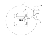
図1に示す車両制御システム1は、車両に搭載される車載機2と、車載機2が搭載される車両(以下、自車両ともいう)9のユーザに携帯される携帯機3と、を備える。車両制御システム1は、自車両9及び他の車両の間での通信(以下、車車間通信)と、自車両9及びインフラ装置の間での通信(以下、路車間通信)と、の少なくとも一方を行う機能を有する。本実施形態では、車両制御システム1は、車車間通信及び路車間通信の両方の機能を有する。また、車両制御システム1は、自車両9のドアの解錠、施錠や、車両9のエンジンの始動等を、機械式のキーを車両9に直接挿入することなく、携帯機3によって実現する機能(以下、スマートエントリ機能)を有する。
Hereinafter, embodiments of the present disclosure will be described with reference to the drawings.
[1. Constitution]
[1-1. overall structure]
A vehicle control system 1 shown in FIG. 1 includes an on-
[1−2.車載機]
車載機2は、照合ECU10と、V2XECU20と、を備える。ECUは、Electronic Control Unitの略である。車載機2は、ドアECU30を備えていてもよい。車載機2は、センサ群50と、DSRC送受信部60と、を備えていてもよい。車載機2は、送受信部40と、ドア開センサ81と、ドアロックセンサ82と、を備えていてもよい。なお、DSRCは、Dedicated Short Range Communicationsの略である。DSRCは登録商標である。
[1-2. In-vehicle device]
The vehicle-mounted
照合ECU10と、V2XECU20と、ドアECU30とは、共通の通信線93によって接続され、通信ネットワークを構成する。照合ECU10と、V2XECU20と、ドアECU30とは、それぞれが、通信ネットワークのノードとして機能し、CAN、LIN等といった所定の通信プロトコルに従って通信を行う。CANは、登録商標である。
The
照合ECU10、V2XECU20、ドアECU30には、電力線91によって、図示しないバッテリから電力が供給されている。具体的には、電力線91によって、バッテリ電圧Bが供給されている。また、照合ECU10、V2XECU20、ドアECU30には、信号線92によって、イグニション信号(以下、IG信号)が供給されている。
Electric power is supplied to the
IG信号は、オン及びオフといった、2つの状態を表わす信号である。すなわち、IG信号は、ハイレベル及びローレベルといった、2値の信号である。IG信号は、自車両9のユーザ100が運転操作を開始したことをきっかけとして出力される。IG信号は、例えば、自車両9のユーザによってエンジンを始動させるための所定のスタートボタンが押下されてから再び押下されるまでの間、又は自車両9のユーザによってイグニションスイッチがオンされてから再びオフされるまでの間、継続してハイレベルが出力される信号である。
The IG signal is a signal that represents two states such as on and off. That is, the IG signal is a binary signal of high level and low level. The IG signal is output when the
以下では、ハイレベルの信号が出力されることを、単に信号が出力される、という。上述の期間以外では、IG信号は、ローレベルである。以下では、ローレベルの信号が出力されることを、信号が出力されない、という。 Hereinafter, outputting a high level signal is simply referred to as outputting a signal. The IG signal is at a low level except for the above period. Below, outputting a low level signal is referred to as not outputting a signal.
センサ群50と、DSRC送受信部60と、出力部70とは、V2XECU20に接続される。
センサ群50は、自車両9の挙動や自車両9の周辺環境等を検出するために必要な各種情報を取得する各種機器やセンサを備える。センサ群50のそれぞれは、V2XECU20へ各種情報を出力する。各種情報は、V2XECU20によって、自車両情報を生成するために利用される。自車両情報とは、自車両9の走行状態を表す情報である。具体的には、センサ群50には、衛星受信部51、レーダセンサ、車速センサ、加速度センサ等が含まれ得る。
The
The
レーダ装置は、例えば、ミリ波センサ、Lidar、音波センサ等であり得る。レーダ装置は、自車両9周辺の物体を検出する。衛星受信部51は、衛星測位システム(以下、GNSS)を構成する準天頂衛星やGPS衛星からの信号を受信する。車速センサは、自車両9の車速を検出するための検出信号を出力する。加速度センサは、自車両9の加速度を検出するための加速度検出信号を出力する。なお、カメラが、センサ群50に含まれていてもよい。カメラは、路面を含む自車両9の進行方向を撮像するよう設置され、画像データを出力するように構成され得る。
The radar device may be, for example, a millimeter wave sensor, a Lidar, a sound wave sensor, or the like. The radar device detects an object around the vehicle 9. The satellite receiver 51 receives signals from the quasi-zenith satellites and GPS satellites that compose the satellite positioning system (hereinafter referred to as GNSS). The vehicle speed sensor outputs a detection signal for detecting the vehicle speed of the host vehicle 9. The acceleration sensor outputs an acceleration detection signal for detecting the acceleration of the vehicle 9. A camera may be included in the
DSRC送受信部60は、本実施形態では、車車間通信及び路車間通信を行う。DSRC送受信部60は、マイクロ波帯の電波を利用して双方向狭域無線通信を可能とする。マイクロ波は、例えば、数GHzの電波であり得る。DSRC送受信部60では、通信可能な範囲が半径数十m〜数百mの大きさに設定されている。
In this embodiment, the
すなわち、DSRC送受信部60は、自車両から半径数十m〜数百m以内に存在する他の車両、及びインフラ装置と通信を行う。インフラ装置には、例えば無線機を搭載して信号情報を送信する信号機等が含まれ得る。
That is, the
DSRC送受信部60は、自車両情報を他の車両に直接送信する。また、DSRC送受信部60は、インフラ装置を利用して自車両情報を他の車両に送信する。また、DSRC送受信部60は、他の車両及びインフラ装置のうち少なくとも一方から、他の車両の走行状態を表す情報(以下、他車両情報)を受信する。なお、自車両9から送信される自車両情報は、他の車両に受信されると、該他の車両によって他車両情報として認識される。
The
出力部70は、ディスプレイ71と、スピーカ72とを備える。ディスプレイ71は、V2XECU20からの指示に従って、画像を表示する。スピーカ72は、V2XECU20からの指示に従って、音声を出力する。
The
送受信部40、ドア開センサ81と、ドアロックセンサ82とは、照合ECU10に接続される。送受信部40は、LF送信部41と、RF受信部42と、を有する。
LF送信部41は、照合ECU10からの指示に従って、自車両9の室内及び周辺に設定された受信範囲Rにて受信可能な強度で、探索電波を出力するよう構成されている。ここでいう探索電波とは、予め定められた周波数の電波であって、本実施形態ではLF帯の電波(以下、LF波)である。LF波は、例えば数十kHz〜百数十kHz程度の、低周波数の電波であり得る。
The transmission/
The
RF受信部42は、携帯機3から無線送信される識別信号を受信する。RF受信部42は、予め定められた周波数のUHF帯の電波(以下、RF波)を受信可能に構成されている。RF波は、例えば数百MHz程度の、高周波数の電波であり得る。
The
ここで、携帯機3について説明する。携帯機3は、LF波を受信すると、識別信号を送信するように構成されている。換言すれば、携帯機3は、図2に示すように、携帯機3が自車両9から受信範囲R内に位置すると、識別信号を、RF波を搬送波として変調を行って、送信するように構成されている。具体的には、携帯機3は、図1に示すように、携帯制御部303を備える。携帯制御部303は、CPU304及びメモリ305を有する、所謂マイクロコンピュータ(以下、マイコン)306を備える。
Here, the
携帯制御部303は、受信部301を介して所定の強度閾値以上の受信強度でLF波を受信すると、送信部302を用いて識別信号を送信する。送信部302は、携帯制御部303から識別信号が出力されると、上述のRF波を搬送波として変調を行って、識別信号を送信する。変調方式には、FM変調、AM変調が含まれ得る。
When the
識別信号とは、予め定められた信号であって、少なくともユーザIDを含む。ユーザIDは、車両制御システム1毎に割り当てられた、予め定められた認識コードであり、メモリ305に記憶されている。
The identification signal is a predetermined signal and includes at least a user ID. The user ID is a predetermined identification code assigned to each vehicle control system 1, and is stored in the
RF受信部42は、このように構成された携帯機3から無線送信されるRF波を受信すると、復調を行って識別信号を取得し、該識別信号を照合ECU10へ出力する。
ドア開センサ81は、自車両9のドアに設けられたタッチセンサである。ユーザ100は、ドアを解錠する際に、つまりドアをアンロックする際に、ドア開センサ81に触れる動作を行う。
Upon receiving the RF wave wirelessly transmitted from the
The door
ドアロックセンサ82は、自車両9のドアに設けられたタッチセンサである。ユーザ100は、自車両9のドアを施錠する際に、つまりドアをロックする際に、ドアロックセンサ82に触れる動作を行う。
The
ドアロックモータ83は、ドアECU30に接続されている。ドアロックモータ83は、ドアECU30の指示に従って、自車両9のドアの施錠、解錠を実行する。
照合ECU10、V2XECU20、及びドアECU30のそれぞれは、CPUと、例えば、RAM又はROM等の半導体メモリ(以下、メモリ)と、を有するマイコンを備える。具体的には、照合ECU10は、マイコン13を備え、マイコン13はCPU11とメモリ12とを有する。V2XECU20は、マイコン23を備え、マイコン23はCPU21とメモリ22とを有する。ドアECU30は、マイコン33を備え、マイコン33はCPU31とメモリ32とを有する。
The door lock motor 83 is connected to the
Each of the
照合ECU10、V2XECU20、及びドアECU30のそれぞれの各種機能は、それぞれのECUが備えるCPU11、21、31が非遷移的実体的記録媒体に格納されたプログラムを実行することにより実現される。この例では、メモリ12、22、32のそれぞれが、プログラムを格納した非遷移的実体的記録媒体に該当する。また、このプログラムが実行されることで、プログラムに対応する方法が実行される。なお、それぞれのECUは、1つのマイコンを備えてもよいし、複数のマイコンを備えてもよい。
The various functions of the
それぞれのECUは、各種機能を実現する手法はソフトウェアに限るものではなく、その一部又は全部の機能は、一つあるいは複数のハードウェアを用いて実現されてもよい。例えば、上記機能がハードウェアである電子回路によって実現される場合、その電子回路は、デジタル回路、又はアナログ回路、あるいはこれらの組合せによって実現されてもよい。 Each ECU is not limited to software for realizing various functions, and some or all of the functions may be realized by using one or a plurality of hardware. For example, when the above function is realized by an electronic circuit that is hardware, the electronic circuit may be realized by a digital circuit, an analog circuit, or a combination thereof.
[1−3.ドアECU]
ドアECU30は、自車両9が操作可能状態に設定されている間、自車両9のドアの施錠と開錠とを行うためのドアロックモータ83を駆動制御する機能を実現するように構成されている。操作可能状態とは、ドアの解錠、施錠やエンジンの始動などの操作が可能な状態をいう。具体的には、操作可能状態では、少なくともドアECU30及びドアロックモータ83に電力が供給される。
[1-3. Door ECU]
The
ドアECU30は、操作可能状態中に、例えば、ユーザ100がドアのハンドルに設けられたドア開センサ81に触れたことが検出されると、ドアロックモータ83にドアを解錠させる指示を出力する。また、ドアECU30は、操作可能状態中に、例えば、ユーザ100がドアのハンドルに設けられたドアロックセンサ82に触れたことが検出されると、ドアロックモータ83にドアを施錠させる指示を出力する。
The
[1−4.V2XECU]
V2XECU20は、マイコン23すなわちCPU21及びメモリ22に加えて、更に、論理和回路25と電源回路24とを備える。
[1-4. V2X ECU]
The
論理和回路25は、少なくともスタートトリガ(以下、ST)信号が入力されると、電源回路24にイネーブル信号を出力するように構成されている。ST信号は、後述するように、照合ECU10から出力される信号である。
The OR
本実施形態では、論理和回路25は、ST信号、IG信号、及び電源コントロール信号(以下、PCNT信号)のうち少なくとも1つが入力されると、電源回路24にイネーブル信号を出力するように構成されている。
In the present embodiment, the
PCNT信号は、マイコン23が実行する起動時処理に基づいて出力される信号である。起動時処理については後述する。PCNT信号は、IG信号が出力されている間、又はマイコン23に電力が供給された後にIG信号が出力されない期間が後述する許容閾値となる迄の間、アサートされる信号である。
The PCNT signal is a signal output based on the startup process executed by the
この信号の目的は、IG信号やST信号がネゲートされた場合に電源回路24の出力Voutをenableのまま保持しておくことである。仮にこの信号が無いと、IG信号やST信号がネゲートされると即座に電源回路24の出力Voutがdisableとなり、CPU21が停止するおそれがある。CPU21はIG信号やST信号がネゲートされると各種情報、例えば自車両の位置など、をROM等に書き込む処理を行う必要があるため、この処理が終わるまでは電源を保持しておく必要がある。
The purpose of this signal is to hold the output V out of the
なお、信号がアサートされるとは、信号が有効にされるという意味であり、ここではハイレベルの信号が出力されることをいう。一方、信号がネゲートされるとは、信号が無効にされるという意味であり、ローレベルの信号が出力されることをいう。 Note that the assertion of a signal means that the signal is validated, and here it means that a high-level signal is output. On the other hand, negating a signal means that the signal is invalidated and that a low level signal is output.
電源回路24は、電力線91に接続されている。電源回路24は、論理和回路25からイネーブル信号が入力されている間、出力Voutをenableとし、論理和回路25からイネーブル信号が入力されていない間、出力Voutをdisableとする。すなわち、電源回路24は、イネーブル信号が入力されている間のみ、マイコン23に、電力線91を介してバッテリ電圧Bを出力Voutとして供給するように構成されている。
換言すれば、電源回路24は、少なくとも照合ECU10から入力されるST信号に従って、ST信号が出力されている間、マイコン23に電力を供給するように構成されている。なお、本実施形態では、論理和回路25及び電源回路24には、電力線91を介して常に電力が供給されている。
The
In other words, the
V2XECU20では、CPU21が後述する起動時処理を実行することによって、マイコン23への電力の供給が開始された際に、起動信号の出力に従って予め定められた指定機能が実行されるように構成されている。起動時処理については後述する。
The
また、V2XECU20では、マイコン23へ電力が供給されている間、CPU21は、例えば数msec〜百msec毎に、センサ群50から出力される各種情報に基づいて自車両情報を生成し、生成した自車両情報をDSRC送受信部60に送信させる機能を実現するように構成されている。
Further, in the
具体的には、CPU21は、衛星受信部51から受信した信号に基づいて、自車両9の現在位置を表す位置情報を生成する処理を実行する。位置情報は、緯度、経度、高度等によって表され得る。また例えば、CPU21は、レーダ装置の検出結果に基づいて、自車両周辺の物体に関する情報(以下、物体検出情報)を生成する処理を実行する。また、CPU21は、車速検出信号に基づいて、自車両9の車速を表す車速情報を生成する処理を実行する。
Specifically, the
また、CPU21は、加速度検出信号に基づいて、自車両9の加速度を表す加速度情報を生成する処理を実行する。物体検出情報には、自車両9から物体までの距離や、自車両9に対する物体の方位等が含まれ得る。CPU21が生成する自車両情報には、位置情報、物体検出情報、車速情報、加速度情報等が自車両の走行状態を表す情報として含まれ得る。
Further, the
更に、CPU21は、例えば数msec〜数百msec毎に、DSRC送受信部60によって、他車両又はインフラ装置から、他車両情報を取得する機能を実現するように構成されている。
Further, the
更に、CPU21は、生成した自車両情報と取得された他車両情報とに基づいて、自車両9と他車両との衝突の可能性を算出するように構成されている。例えば、CPU21は、自車両9から他車両迄の距離、自車両9及び他車両の進行方向、自車両9及び他車両の車速等に基づいて、自車両9と他車両とが衝突するまでの時間を算出する。
Further, the
更に、CPU21は、出力部70に、算出結果に応じてドライバに衝突を回避するための報知を行わせる指示を出力する機能を実現するように構成されている。CPU21は、ディスプレイ71に報知の為の画像を表示させるように構成されてもよいし、スピーカ72に報知の為の音声を出力させるように構成されてもよい。
Further, the
[1−5.照合ECU]
照合ECU10では、メモリ12に、少なくとも上述のユーザIDが記憶されている。
照合ECU10では、CPU11は、照合処理を実行することによって、所定の周期で、探索電波であるLF波を出力する。また、CPU11は、照合処理を実行することによって、所定の条件が満たされた場合に、実行装置へ電力を供給するように構成されている。実行装置とは、自車両9に搭載された予め定められた装置である。照合処理については後述する。
[1-5. Verification ECU]
In the
In the
また、照合ECU10は、操作可能状態中は、ユーザ100によって車室内の特定の始動ボタンが押下されると、エンジンを始動させる機能を実現するように構成されている。
照合ECU10では、CPU11は、携帯機3からユーザIDを含む識別信号を受信すると、メモリ12に予め登録されているユーザIDとの照合を行い、これらのユーザIDが一致した場合は、自車両9を操作可能状態とする機能を実現するように構成されていてもよい。
Further, the
In the
なお、照合ECU10は、電力線91によってバッテリ電圧Bが常に供給されている。
[2.処理]
[2−1.照合処理]
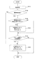
次に、照合ECU10にてCPU11が実行する照合処理について、図3のフローチャートを用いて説明する。照合処理は、携帯機3が自車両9から所定の受信範囲R内に位置することが検出された場合に、実行装置へ電力を供給する電力供給部に供給指示を出力するための処理である。これにより、実行装置へ電力が供給される。供給指示とは、電力供給部に、実行装置への電力を供給させるための指示である。電力供給部とは、実行装置に電力を供給するための装置である。
The
[2. processing]
[2-1. Matching process]
Next, the matching process executed by the
本実施形態では、実行装置は、自車両9に関する情報である自車両情報を取得し、自車両9の周囲に位置する他の車両及び自車両の周囲に位置する道路装置のうち少なくとも一方に、自車両情報をDSRC送受信部60によって少なくとも送信するように構成されている。道路装置とは、上述のインフラ装置のことである。つまり、本実施形態では、マイコン23が実行装置に相当し、電源回路24が電力供給部に相当し、ST信号が供給指示に相当する。
In the present embodiment, the execution device acquires own vehicle information, which is information about the own vehicle 9, and at least one of other vehicles located around the own vehicle 9 and a road device located around the own vehicle, The own-vehicle information is configured to be transmitted at least by the
照合処理は、例えば数msec〜数百msecといった、予め定められた実行周期で繰り返し実行される。
CPU11は、S110では、電波照合を実行する。具体的には、CPU11は、LF送信部41に探索電波であるLF波を送信させるための指示を出力する。これにより、予め定められた実行周期でLF波が送信される。上述のように、携帯機3は、自車両9のユーザに携帯され、車載機2から送信されたLF波を受信すると、ユーザIDを含む識別信号を、LF波よりも高い周波数の電波であるRF波を搬送波として用いて、送信する。
The collation process is repeatedly executed at a predetermined execution cycle such as several msec to several hundred msec.
The
CPU11は、RF受信部42によって携帯機3から識別信号を受信したか否かを繰り返し判断し、識別信号を受信したと判断された場合に、携帯機3が自車両9から所定の範囲である受信範囲R内に位置すると特定する。更に、CPU11は、携帯機3から受信した識別信号に含まれるユーザIDとメモリ12に予め記憶されているユーザIDとが一致するか否かを判断する。
The
CPU11はこれらのユーザIDが一致する場合に、自車両9に対応する携帯機3が受信範囲R内に位置すると特定する。自車両9に対応する携帯機3とは、当該車両制御システム1用に予め登録されている携帯機3をいう。なお、以下で、携帯機3が検出されると記載した場合は、自車両9に対応する携帯機3が自車両9から受信範囲R内に位置することを意味する。
When these user IDs match, the
CPU11は、S120では、携帯機3を検出したか否かを判断する。CPU11は、携帯機3が検出されたと判断された場合に処理をS130へ移行させ、携帯機3が検出されていないと判断された場合に処理をS160へ移行させる。
In S120, the
CPU11は、S130では、携帯機3が初めて検出されたか否かを判断する。ここでいう携帯機3が初めて検出されたとは、携帯機3が受信範囲R外から受信範囲R内に侵入した際の携帯機3の検出、及び、後述するアサート時間が継続閾値以上となった後の携帯機3の検出、を含む。具体的には、CPU11は、検出フラグがリセット値に設定されているか否かを判断し、検出フラグがリセット値に設定されている場合に携帯機3が初めて検出されたと判断する。検出フラグは、初期値がリセット値に設定されており、携帯機3が検出されている間はリセット値とは異なるセット値に設定されるフラグである。例えば、リセット値は0であり、セット値は1であり得る。検出フラグは、メモリ12に記憶される。
In S130, the
ここで、CPU11は、検出フラグがリセット値に設定されており、携帯機3が検出されたと判断された場合に、携帯機3が初めて検出されたと判断し、検出フラグをセット値に設定して処理をS140へ移行させる。一方、CPU11は、検出フラグがセット値に設定されている場合は、携帯機3が既に検出されており、且つ該携帯機3が継続して検出されていると判断し、処理をS150へ移行させる。
Here, when the detection flag is set to the reset value and it is determined that the
更に、CPU11は、本ステップでは、電力供給部に供給指示を出力する。上述の実行装置は、携帯機3が自車両9から受信範囲R内に位置すると特定された場合に、供給指示に従って電力供給部によって電力が供給されるように構成されている。
Further, in this step, the
具体的には、CPU11は、電源回路24にST信号を出力する。なお、本実施形態では、CPU11は、ST信号をアサートし、該ST信号をV2XECU20へ、具体的には論理和回路25へ出力する。上述のように、ST信号がアサートされている間、論理和回路25からはイネーブル信号が出力される。イネーブル信号が入力されている間、電源回路24はマイコン23へ電力を供給する。
Specifically, the
つまり、電源回路24は、ST信号に従って、少なくともST信号が出力されている間、マイコン23に対して、つまり少なくともCPU21及びメモリ22に対して、電力を供給する。これにより、マイコン23では、電力が供給されたことをきっかけとして、CPU21が後述する起動時処理を実行する。
That is, the
また、CPU11は、本ステップでは、検出フラグをセット値に設定する。本実施形態では、CPU11は、検出フラグを1に設定する。また、CPU11は、本ステップでは、タイマをスタートさせ、ST信号がアサートされている時間(以下、アサート時間)TAの測定を開始する。タイマは、マイコンが備える機能に予め含まれている。そして、CPU11は、処理をS150へ移行させる。
Further, the
CPU11は、S150では、アサート時間TAが予め定められた継続閾値以上であるか否かを判断する。継続閾値は、例えば、数min〜数十min程度の任意の値に設定され得る。CPU11は、アサート時間TAが継続閾値以上である場合に処理をS160へ移行させ、アサート時間TAが継続閾値未満である場合に照合処理を終了する。なお、継続閾値は、ユーザ100が受信範囲R内に侵入してから運転操作を開始する迄の一般的な所要時間、バッテリ容量、V2XECU20の消費電流等を考慮して設定され得る。
In S150, the
CPU11は、S160では、V2XECU20具体的には論理和回路25へ出力されていたST信号をネゲートする。また、CPU11は、検出フラグをリセット値に設定する。本実施形態では、CPU11は、検出フラグを0に設定する。また、CPU11は、タイマをリセットする。本実施形態では、タイマがリセットされると、アサート時間TAが0に設定し直される。以上で、CPU11は、照合処理を終了する。
In S160, the
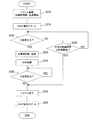
[2−2.起動時処理]
次に、起動時処理について説明する。起動時処理は、車載機2が備える実行装置が実行する処理である。起動時処理は、実行装置への電力の供給開始をきっかけとして、開始される。実行装置は、該実行装置への電力の供給が開始された際に、起動時処理を実行することによって、起動信号の出力に従って予め定められた指定機能が実行されるように構成されている。
[2-2. Processing at startup]
Next, the startup process will be described. The startup process is a process executed by the execution device included in the vehicle-mounted
起動信号とは、自車両9のユーザ100が自車両9を起動したことを表す信号である。起動とは、運転操作を開始することである。運転操作を開始するとは、所定のスタートボタンを押下したりイグニションスイッチをオンしたりすることによって、エンジンを始動させることをいう。換言すれば、起動信号とは、自車両9のユーザ100が運転操作を開始したことを表す信号である。本実施形態では、IG信号が起動信号に相当する。また、本実施形態では、上述のようにマイコン23が実行装置に相当し、後述するBSM送信を行う機能が指定機能に相当する。
The activation signal is a signal indicating that the
以下では、実行装置であるマイコン23にてCPU21が実行する起動時処理について、図4のフローチャートを用いて説明する。該起動時処理は、マイコン23への電力の供給開始をきっかけとして開始される。マイコン23への電力の供給は、上述のように、電源回路24に少なくともST信号が出力されることよって開始される。
The startup process executed by the
CPU21は、S200では、システム起動を実行する。システム起動とは、所謂立ち上げ処理のことであり、マイコンが備える種々の機能を実現するための準備を行うことをいう。システム起動には、例えば、マイコンが有するメモリにおけるROMに記憶されているプログラムをRAMに読み込む、といった処理が含まれ得る。
The
CPU21は、S210では、PCNT信号をアサートする。PCNT信号は、論理和回路25へ出力される信号である。これにより、PCNT信号がアサートされている間は、当該CPU21を含むマイコン23に、電力が供給される。
The
CPU21は、S220では、IG信号が出力されているか否かを判断する。CPU21は、IG信号が出力されていると判断された場合に処理をS240へ移行させ、IG信号が出力されていないと判断された場合に、処理をS230へ移行させる。なお、マイコン23では、起動時処理とは別の処理を実行することによって、PCNT信号がアサートされ、且つ、IG信号が出力されていない期間であるPCNT経過時間TP、の計測が実行されている。PCNT経過時間TPは、マイコン23に含まれるタイマによって計測される。
In S220, the
CPU21は、S230では、PCNT経過時間TPが所定の許容閾値以上であるか否かを判断する。許容閾値は、例えば数minに設定され得る。CPU21は、PCNT経過時間TPが許容閾値以上である場合に処理をS270へ移行させ、PCNT経過時間TPが許容閾値未満である場合に処理をS220へ移行させる。
In S230, the
CPU21は、S240では、自車両情報を取得する。そして、CPU21は、処理をS250へ移行させる。自車両情報は、CPU21が本起動時処理とは異なる処理を実行することによって、予め定められた周期で繰り返し生成されており、メモリ22に記憶されている。CPU21は、本ステップでは、メモリ22に記憶されている最新の自車両情報を取得する。
CPU21 acquires own vehicle information in S240. Then, the
CPU21は、S250では、指定機能を実行する。そして、CPU21は、処理をS260へ移行させる。指定機能とは、電力が供給されている実行装置において、IG信号の出力開始をきっかけとして実行される、予め定められた機能である。本実施形態では、BSM送信を行う機能が指定機能に相当する。
The
BSMは、Basic Safety Messageの略である。本実施形態では、少なくとも自車両情報がBSMに含まれ得る。すなわち、ここでいうBSM送信とは、DSRC送受信部60を用いて、車車間通信及び路車間通信によって、自車両情報を送信することをいう。なお、CPU21は、自車両9を他の車両と識別可能とする識別コードと共に、自車両情報を送信するよう構成されてもよい。該識別コードは、メモリ22に記憶されていてもよい。
BSM is an abbreviation for Basic Safety Message. In the present embodiment, at least the own vehicle information may be included in the BSM. That is, the BSM transmission here means transmitting the own vehicle information by the inter-vehicle communication and the road-vehicle communication using the
CPU21は、S260では、IG信号が出力されているか否かを判断する。ここで、CPU21は、IG信号が出力されていると判断された場合は、IG信号が出力されなくなる迄待機する。一方、CPU21は、IG信号が出力されなくなったと判断された場合は、処理をS270へ移行させる。
In S260, the
CPU21は、S270では、システム終了を行い、処理をS280へ移行させる。システム終了では、起動時処理にて生成又は取得された各種情報であってこの時点における最新の各種情報、をメモリ22に記憶するといった処理が含まれ得る。本実施形態では、システム終了にてメモリ22に記憶される各種情報には、この時点における最新の自車両情報や他車両情報が含まれ得る。
In S270, the
CPU21は、S280では、PCNT信号をネゲートする。これにより、論理和回路25へのPCNT信号の出力が停止する。CPU21は、以上で起動時処理を終了する。
The
このように、実行装置は、起動時処理によって、はじめにシステム起動が行われるように構成されている。また、実行装置は、起動時処理によって、システム起動後の起動信号の出力開始に従って、指定機能を実現するように構成されている。 In this way, the execution device is configured such that the system is first started by the startup process. Further, the execution device is configured to realize the designated function by the start-up process, in accordance with the start of output of the start signal after the system is started.
[3.作動]
以上のように構成された車両制御システム1は、次のように作動する。
[3−1.実行装置の起動]
照合ECU10では、CPU11は、上述の実行周期で繰り返しLF波を出力する。CPU11は、携帯機3が自車両9から所定の受信範囲R内に位置するという所定の条件が満たされた場合に、供給指示であるST信号を出力する。つまり、電源回路24によって、実行装置であるマイコン23へ電力の供給が開始される。
[3. Operation]
The vehicle control system 1 configured as described above operates as follows.
[3-1. Execution unit startup]
In the
マイコン23は、当該マイコン23への電力の供給開始をきっかけとして、はじめにシステム起動を行う。更に、マイコン23は、システム起動後にIG信号の出力開始をきっかけとして、少なくとも指定機能であるBSM送信を実行する。つまり、電力の供給が開始されているマイコン23によって、IG信号の出力開始後速やかに、自車両情報がDSRC送受信部60を介して送信される。
The
また、マイコン13では、CPU11は、携帯機3が自車両9から所定の受信範囲R内に位置することが検出されてからの経過時間であるアサート時間TAが継続閾値以上になると、ST信号の出力を停止する。
In addition, in the
例えば、携帯機3を携帯したユーザ100が、受信範囲R外から受信範囲R内に入り自車両9に乗り込んだ後、自車両9内において居眠りをしてしまい運転操作を開始しないような状況が生じることが有り得る。このような場合、仮にST信号をアサートし続けてマイコン23に電力を供給し続けることで、バッテリ上がりとなるおそれがある。
For example, there is a situation where the
本実施形態では、CPU11は、アサート時間TAが継続閾値以上になるとST信号の出力を停止するので、バッテリ上がりが抑制される。
なお、本実施形態では、IG信号が出力された以降であってIG信号の出力が継続されている間、又はPCNT信号が出力された以降であってPCNT信号の出力が継続されている間は、マイコン23へ電力が供給される。このため、このようにIG信号が出力されている間、又はこのようにPCNT信号が出力されている間は、ST信号の出力の有無に拘わらずマイコン23へ電力が供給され、マイコン23によってV2XECU20としての種々の機能が実現される。
In the present embodiment, the
In the present embodiment, after the IG signal is output and while the IG signal is continuously output, or after the PCNT signal is output and while the PCNT signal is continuously output, , Electric power is supplied to the
[3−2.車車通信及び路車間通信]
マイコン23に電力が供給されている間は、マイコン23によって、数msec〜百msec毎に、自車両情報が生成され、他車両情報が取得される。このようにして、車車間通信及び路車間通信が実現される。また、マイコン23によって、自車両情報と他車両情報とに基づいて自車両と他車両との衝突の可能性が算出され、算出結果に応じてドライバに衝突を回避するための報知が行われる。
[3-2. Vehicle-to-vehicle communication and road-to-vehicle communication]
While electric power is being supplied to the
[3−3.スマートエントリ機能]
操作可能状態中は、ユーザ100が例えばドア開センサ81に触れると、ドアECU30によってドアが解錠される。また、操作可能状態中は、ユーザ100が例えばドアロックセンサ82に触れると、ドアECU30によってドアが施錠される。また、操作可能状態中は、ユーザ100が始動ボタンを押下すると、照合ECU10によってエンジンの始動が行われる。車両制御システム1では、このようにして、スマートエントリ機能が実現される。
[3-3. Smart entry function]
When the
[4.効果]
以上詳述した実施形態によれば、以下の効果を奏する。
(4a)車載機2において、照合ECU10すなわちマイコン13は、S110では、探索電波であるLF波をLF送信部41に繰り返し出力させるように構成されている。照合ECU10は、S120では、携帯機3から識別信号をRF受信部42によって受信したか否かを繰り返し判断する。携帯機3は、自車両9のユーザに携帯される通信機である。携帯機3は、LF波を受信すると、予め定められた識別信号を、LF波よりも高い周波数の電波であるRF波を搬送波として用いて、送信する。
[4. effect]
According to the embodiment described in detail above, the following effects are achieved.
(4a) In the vehicle-mounted
そして、照合ECU10は、携帯機3から識別信号を受信したと判断された場合に、携帯機3が自車両9から所定範囲である受信範囲R内に位置すると特定する。照合ECU10は、S140では、携帯機3が自車両9から受信範囲R内に位置すると特定された場合に、実行装置に対して電力を供給する電力供給部に供給指示を出力するように構成されている。実行装置は自車両9に搭載された予め定められた装置であり、電力供給部は供給指示に従って供給指示が出力されている間電力を供給する装置である。
Then, when it is determined that the identification signal is received from the
一般には、自車両のユーザが車室内に乗り込んで自車両の運転操作を開始した後に実行装置に電力が供給され、実行装置は、電力が供給され且つ該実行装置の立ち上げ等に必要な予め定められた期間の経過後に、作動を開始する。運転操作が開始されると、起動信号であるIG信号の出力が開始される。 Generally, after the user of the own vehicle gets into the passenger compartment and starts driving operation of the own vehicle, electric power is supplied to the execution device, and the execution device is supplied with power and necessary in advance for starting the execution device. The operation is started after the lapse of the defined period. When the driving operation is started, the output of the IG signal which is a start signal is started.
これに対し、車両制御システム1では、携帯機3が自車両9から所定の受信範囲R内に位置することが特定された場合には、自車両9のユーザが自車両9内に乗り込んで運転操作を開始する前に、実行装置に電力が供給される。上述のように、実行装置は、電力の供給が開始されると、はじめにシステム起動が実行されるように構成されている。
On the other hand, in the vehicle control system 1, when it is specified that the
その結果、自車両9のユーザ100が車室内に乗り込んで自車両9の運転操作を開始する際には、実行装置に既に電力が供給され且つ電力が供給されてから時間が経過しているので、車両の運転操作の開始後に実行装置を速やかに作動させることができる。
As a result, when the
ここでいう作動とは、システム起動後に実行装置がプログラムに従って該実行装置に割り当てられた所定の種々の機能を実現すること、を含む。実行装置は、少なくともマイコンを備える装置である。
なお、近年、実行装置として実現する機能の複雑化等によってプログラムの容量が大きくなり、システム起動のために必要とされる時間が増加する傾向にある。車両制御システム1では、上述のように運転操作開始前に予め実行装置に電力が供給されるので、システム起動のために必要とされる時間が長時間である実行装置においても、車両の運転操作の開始後速やかに実行装置を作動させることができる。
The operation here includes that the execution device realizes various predetermined functions assigned to the execution device according to a program after the system is activated. The execution device is a device including at least a microcomputer.
It should be noted that in recent years, the capacity of programs has increased due to the complexity of functions implemented as an execution device, and the time required for system startup tends to increase. In the vehicle control system 1, as described above, electric power is supplied to the execution device before the start of the driving operation. Therefore, even in the execution device in which the time required for system startup is long, the driving operation of the vehicle The execution device can be operated promptly after the start of.
(4b)照合ECU10は、S150では、携帯機3が自車両9から受信範囲R内に位置すると特定されてからの経過時間であるアサート時間TAを取得する。そして、照合ECU10は、アサート時間TAが時間閾値である継続閾値以上であるか否かを判断するように構成されている。照合ECU10は、S140では、アサート時間Tが継続閾値未満である場合に、電力供給部である電源回路24に供給指示であるST信号を出力する。且つ、照合ECU10は、S160では、アサート時間TAが継続閾値以上である場合に、電源回路24へのST信号の出力を停止するように構成されている。
(4b) In S150, the
その結果、例えば携帯機3を携帯したユーザ100が自車両9に乗り込んだ後に運転操作を開始しないような状況が生じた場合に、バッテリ上がりを抑制することができる。
(4c)実行装置は、供給指示に従って電力供給部によって電力が供給されているときに、自車両9のユーザ100が自車両9を起動したことを表す起動信号としてのイグニション信号の出力に従って、予め定められた指定機能を実行するように構成されている。
As a result, when the
(4c) The execution device preliminarily follows the output of an ignition signal as a start signal indicating that the
その結果、自車両9のユーザ100が自車両9を起動した場合に、実行装置において指定機能を速やかに実行することができる。
(4d)本実施形態では、実行装置は、マイコン23である。マイコン23は、自車両9に関する情報である自車両情報を取得し、自車両9の周囲に位置する他の車両及び自車両の周囲に位置する道路装置のうち少なくとも一方に、自車両情報をDSRC送受信部60によって少なくとも送信するように構成されている。
As a result, when the
(4d) In this embodiment, the execution device is the
その結果、車車間通信及び路車間通信を行う機能を備える装置であるマイコン23を運転操作開始後速やかに作動させることができる。
(4e)マイコン23は、少なくとも自車両情報を送信する機能を上述の指定機能として有するように構成されている。
As a result, the
(4e) The
車車間通信及び路車間通信を行う機能を備える装置であるマイコン23では、自車両9の運転操作の開始後速やかに、自車両情報が送信されることが望ましい。具体的には、数SEC以内に、自車両情報が送信されることが望ましい。
In the
車載機2では、自車両9の運転操作開始前にマイコン23に電力が供給され、且つ、運転操作開始後に指定機能としての自車両情報の送信が実行されるように構成される。その結果、自車両情報が運転操作開始直後速やかに送信されるので、運転操作開始直後速やかに、他の車両に自車両9を認識させることが可能となる。ひいては、他の車両に自車両9との衝突を回避させることが可能となる。
The vehicle-mounted
[5.他の実施形態]
以上、本開示の実施形態について説明したが、本開示は上述の実施形態に限定されることなく、種々変形して実施することができる。
[5. Other Embodiments]
Although the embodiments of the present disclosure have been described above, the present disclosure is not limited to the above-described embodiments, and various modifications can be implemented.
(5a)上記実施形態では、車載機2は、車車間通信及び路車間通信の両方の機能を有するように構成されていたが、これに限定されるものではない。車載機2は、車車間通信及び路車間通信のうち少なくとも一方の機能を有するように構成されていてもよい。
(5a) In the above-described embodiment, the vehicle-mounted
(5b)車載機2は、例えば、所定の信号であるリクエスト信号がLF波を搬送波として変調された電波を探索電波として定期的に送信するように構成されてもよい。そして、携帯機3は、受信したLF波を復調してリクエスト信号が含まれていた場合に、ユーザIDに加えて所定の信号である応答信号を含む識別信号を、RF波を搬送波として変調し、送信するように構成されていてもよい。そして、車載機2は、受信したRF波を復調して応答信号が含まれていた場合に、ユーザIDの照合を実行するように構成されていてもよい。
(5b) The vehicle-mounted
(5c)実行装置は、運転操作開始後の経過時間が所定時間以内に、指定機能を実行するように構成されてもよい。例えば、マイコン23は、運転操作開始後、すなわちIG信号の出力開始後、所定時間内に上述の指定機能を実行するように構成されてもよい。所定時間は、例えば数SEC以内に設定され得る。その結果、マイコン23では、指定機能が運転操作開始後数SEC以内に確実に実行される。
(5c) The execution device may be configured to execute the designated function within a predetermined time after the start of the driving operation. For example, the
(5d)車載機2では、マイコン23は、少なくとも、他車両情報を受信する機能を指定機能として有するように構成されていてもよい。その結果、自車両9の運転操作開始直後において、自車両9にて他の車両を認識することが可能となる。マイコン23は、更に、自車両情報と他車両情報とに基づいて、自車両9と他車両との衝突の可能性を算出する機能を指定機能として有するように構成されていてもよい。その結果、自車両9にて他の車両との衝突を回避することが可能となる。
(5e)上記実施形態では、マイコン23が実行装置である例を記載したが、これに限定されるものではない。実行装置は、自車両9に搭載され、少なくともマイコンを備え、システム起動に所定の時間を必要とし、種々の機能を実現するための装置であり得る。
(5d) In the vehicle-mounted
(5e) In the above embodiment, the example in which the
(5f)上記実施形態における1つの構成要素が有する複数の機能を、複数の構成要素によって実現したり、1つの構成要素が有する1つの機能を、複数の構成要素によって実現したりしてもよい。また、複数の構成要素が有する複数の機能を、1つの構成要素によって実現したり、複数の構成要素によって実現される1つの機能を、1つの構成要素によって実現したりしてもよい。また、上記実施形態の構成の一部を省略してもよい。また、上記実施形態の構成の少なくとも一部を、他の上記実施形態の構成に対して付加又は置換してもよい。なお、特許請求の範囲に記載した文言から特定される技術思想に含まれるあらゆる態様が本開示の実施形態である。 (5f) A plurality of functions of one constituent element in the above embodiment may be realized by a plurality of constituent elements, or one function of one constituent element may be realized by a plurality of constituent elements. .. Further, a plurality of functions of a plurality of constituent elements may be realized by one constituent element, or one function realized by a plurality of constituent elements may be realized by one constituent element. Moreover, you may omit a part of structure of the said embodiment. Further, at least a part of the configuration of the above-described embodiment may be added or replaced with respect to the configuration of the other above-described embodiment. Note that all aspects included in the technical idea specified by the wording recited in the claims are embodiments of the present disclosure.
(5g)上述したCPU11、CPU21、マイコン13、マイコン23、照合ECU10、V2XECU20、車載機2、携帯機3、車両制御システム1、当該CPU11、当該CPU21としてコンピュータを機能させるためのプログラム、このプログラムを記録した半導体メモリ等の非遷移的実態的記録媒体、実行装置の起動方法など、種々の形態で本開示を実現することもできる。
(5g) The above-mentioned
なお、上記実施形態において、照合ECU10が車両制御装置に相当し、LF送信部41が送信機に相当し、RF受信部42が受信機に相当し、マイコン23が実行装置に相当し、電源回路24が電力供給部に相当し、DSRC送受信部60が情報送信装置に相当する。インフラ装置が道路装置に相当する。また、送信指示部、携帯機検出部、供給指示部、時間判断部が照合ECU10に相当する。また、S110が送信指示部としての処理に相当し、S120が携帯機検出部としての処理に相当し、S140、S160が供給指示部としての処理に相当し、S150が時間判断部としての処理に相当する。
In the above embodiment, the
また、LF波が探索電波に相当し、応答信号及びユーザIDの少なくとも一方が識別信号に相当し、IG信号が起動信号に相当する。また、ST信号をアサートすることが供給指示を出力することに相当し、ST信号をネゲートすることが供給指示の出力を停止することに相当する。また、継続閾値が時間閾値に相当する。 Further, the LF wave corresponds to the search radio wave, at least one of the response signal and the user ID corresponds to the identification signal, and the IG signal corresponds to the activation signal. Further, asserting the ST signal corresponds to outputting the supply instruction, and negating the ST signal corresponds to stopping output of the supply instruction. Further, the continuation threshold value corresponds to the time threshold value.
2 車載機、3 携帯機、9 自車両、10 照合ECU、23 マイコン、24 電源回路、41 LF送信部、42 RF受信部、60 DSRC送受信部、100 ユーザ。 2 vehicle-mounted device, 3 portable device, 9 own vehicle, 10 verification ECU, 23 microcomputer, 24 power supply circuit, 41 LF transmitter, 42 RF receiver, 60 DSRC transceiver, 100 users.
Claims (4)
予め定められた周波数の電波である探索電波を送信機(41)に出力させるように構成された送信指示部(10、S110)と、
当該車両制御装置が搭載される車両である自車両のユーザに携帯される携帯機であって前記探索電波を受信すると予め定められた識別信号を送信するように構成された携帯機から、前記識別信号を受信機(42)によって受信したか否かを繰り返し判断し、前記識別信号を受信したと判断された場合に前記携帯機が自車両から所定の範囲である受信範囲内に位置すると特定するように構成された携帯機検出部(10、S120)と、
前記携帯機が自車両から前記受信範囲内に位置すると特定された場合に、供給指示に従って自車両に搭載された予め定められた実行装置(23)に対して電力を供給する電力供給部(24)に、前記供給指示を出力するように構成された供給指示部(10、S140)と、
を備え、
前記実行装置は、前記供給指示に従って前記電力供給部によって電力が供給されているときに、前記自車両のユーザが自車両を起動したことを表す起動信号に従って予め定められた指定機能を実行するように構成された
車両制御装置。 A vehicle control device (2) mounted on a vehicle, comprising:
A transmission instruction section (10, S110) configured to output a search radio wave having a predetermined frequency to the transmitter (41);
From the portable device that is carried by the user of the own vehicle, which is the vehicle in which the vehicle control device is installed, and that is configured to transmit a predetermined identification signal when receiving the search radio wave, the identification is performed. It is repeatedly determined whether or not a signal is received by the receiver (42), and when it is determined that the identification signal is received, it is specified that the portable device is located within a reception range which is a predetermined range from the own vehicle. A portable unit detection unit (10, S120) configured as described above,
When it is determined that the portable device is located within the reception range from the own vehicle, a power supply unit (24) that supplies power to a predetermined execution device (23) mounted on the own vehicle according to a supply instruction. ), a supply instruction unit (10, S140) configured to output the supply instruction,
Equipped with,
The execution device is configured to execute a predetermined designated function according to a start signal indicating that the user of the own vehicle has started the own vehicle when power is being supplied by the power supply unit according to the supply instruction. Configured to
Vehicle control device.
前記実行装置は、自車両に関する情報である自車両情報を取得し、自車両の周囲に位置する他の車両及び自車両の周囲に位置する道路装置のうち少なくとも一方に、前記自車両情報を情報送信装置(60)によって少なくとも送信するように構成された
車両制御装置。 The vehicle control device according to claim 1 , wherein
The execution device obtains own vehicle information, which is information about the own vehicle, and provides the own vehicle information to at least one of another vehicle located around the own vehicle and a road device located around the own vehicle. A vehicle controller configured to at least transmit by a transmitter (60).
前記実行装置は、少なくとも前記自車両情報を送信する機能を前記指定機能として有するように構成された
車両制御装置。 The vehicle control device according to claim 2 , wherein
The execution device is configured to have at least a function of transmitting the own vehicle information as the designated function.
前記携帯機が自車両から前記受信範囲内に位置すると特定されてからの経過時間を取得し、前記経過時間が予め定められた時間閾値以上であるか否かを判断するように構成された時間判断部(10、S150)を更に備え、
前記供給指示部は、前記経過時間が前記時間閾値未満である場合に、前記電力供給部へ前記供給指示を出力し(S140)、且つ、前記経過時間が前記時間閾値以上である場合に、前記電力供給部への前記供給指示の出力を停止する(S160)ように構成された
車両制御装置。 The vehicle control device according to any one of claims 1 to 3 ,
A time period configured to acquire the elapsed time from when the portable device is located within the reception range from the host vehicle and determine whether the elapsed time is equal to or greater than a predetermined time threshold value. The determination unit (10, S150) is further provided,
The supply instruction unit outputs the supply instruction to the power supply unit when the elapsed time is less than the time threshold (S140), and when the elapsed time is equal to or more than the time threshold, The vehicle control device configured to stop outputting the supply instruction to the power supply unit (S160).
Priority Applications (4)
| Application Number | Priority Date | Filing Date | Title |
|---|---|---|---|
| JP2018098990A JP6724944B2 (en) | 2018-05-23 | 2018-05-23 | Vehicle control device |
| GB2018383.6A GB2588014B (en) | 2018-05-23 | 2019-05-22 | Vehicle control device |
| PCT/JP2019/020338 WO2019225666A1 (en) | 2018-05-23 | 2019-05-22 | Vehicle control device |
| US16/950,587 US20210061222A1 (en) | 2018-05-23 | 2020-11-17 | Vehicle control device |
Applications Claiming Priority (1)
| Application Number | Priority Date | Filing Date | Title |
|---|---|---|---|
| JP2018098990A JP6724944B2 (en) | 2018-05-23 | 2018-05-23 | Vehicle control device |
Publications (3)
| Publication Number | Publication Date |
|---|---|
| JP2019204285A JP2019204285A (en) | 2019-11-28 |
| JP2019204285A5 JP2019204285A5 (en) | 2020-03-12 |
| JP6724944B2 true JP6724944B2 (en) | 2020-07-15 |
Family
ID=68615839
Family Applications (1)
| Application Number | Title | Priority Date | Filing Date |
|---|---|---|---|
| JP2018098990A Active JP6724944B2 (en) | 2018-05-23 | 2018-05-23 | Vehicle control device |
Country Status (4)
| Country | Link |
|---|---|
| US (1) | US20210061222A1 (en) |
| JP (1) | JP6724944B2 (en) |
| GB (1) | GB2588014B (en) |
| WO (1) | WO2019225666A1 (en) |
Family Cites Families (6)
| Publication number | Priority date | Publication date | Assignee | Title |
|---|---|---|---|---|
| US7584026B2 (en) * | 2006-04-19 | 2009-09-01 | Edward D. Siemer, Jr. | Wirelessly controlled motorized vehicle system |
| US8280791B2 (en) * | 2009-12-08 | 2012-10-02 | At&T Mobility Ii Llc | Devices, systems and methods for identifying and/or billing an individual in a vehicle |
| JP5803627B2 (en) * | 2011-12-05 | 2015-11-04 | 株式会社デンソー | In-vehicle display device |
| JP2014081872A (en) * | 2012-10-18 | 2014-05-08 | Denso Corp | Vehicle information processor |
| US9086879B2 (en) * | 2013-07-26 | 2015-07-21 | GM Global Technology Operations LLC | Methods and apparatus for optimizing battery life in a remote device |
| JP2017093066A (en) * | 2015-11-05 | 2017-05-25 | トヨタ自動車株式会社 | vehicle |
-
2018
- 2018-05-23 JP JP2018098990A patent/JP6724944B2/en active Active
-
2019
- 2019-05-22 GB GB2018383.6A patent/GB2588014B/en active Active
- 2019-05-22 WO PCT/JP2019/020338 patent/WO2019225666A1/en active Application Filing
-
2020
- 2020-11-17 US US16/950,587 patent/US20210061222A1/en active Pending
Also Published As
| Publication number | Publication date |
|---|---|
| GB2588014B (en) | 2022-05-11 |
| JP2019204285A (en) | 2019-11-28 |
| GB2588014A (en) | 2021-04-14 |
| GB202018383D0 (en) | 2021-01-06 |
| WO2019225666A1 (en) | 2019-11-28 |
| US20210061222A1 (en) | 2021-03-04 |
Similar Documents
| Publication | Publication Date | Title |
|---|---|---|
| US10518698B2 (en) | System and method for generating a parking alert | |
| US11953898B2 (en) | Vehicle remote operation system | |
| JP6167527B2 (en) | Vehicle system, electronic key, portable terminal, and in-vehicle device | |
| CN105917586B (en) | Bluetooth verifying for vehicle access system | |
| CN105934777B (en) | Remote vehicle for fleet vehicle accesses system | |
| JP6451441B2 (en) | User identification system, portable device for vehicles | |
| CN109150946B (en) | System and method for vehicle identification using a mobile device | |
| JP5268663B2 (en) | In-vehicle electronic key system and vehicle | |
| US20190338562A1 (en) | Vehicle electronic key | |
| CN110636949A (en) | Tire pressure detection system | |
| JP4404100B2 (en) | Vehicle control system and vehicle-mounted device | |
| JP5508241B2 (en) | Electronic key system | |
| JP6724944B2 (en) | Vehicle control device | |
| CN109542526A (en) | A kind of starting method and device of in-car entertainment system | |
| JP6988691B2 (en) | Driving support device, driving support method and computer program | |
| JP2014151846A (en) | Power consumption reduction device for vehicle | |
| JP2016099831A (en) | On-vehicle apparatus | |
| JP7468091B2 (en) | Vehicle-mounted device for toll payment, mobile communication terminal, toll payment system, and terminal control program | |
| JP7416670B2 (en) | Communication control device, vehicle equipped with the same, and communication control method | |
| JP2017187957A (en) | Periphery monitoring system | |
| JP2019084947A (en) | Vehicle surroundings monitoring device | |
| WO2019044544A1 (en) | Onboard appliance, communication system for vehicles, and communication processing method | |
| CN110691980A (en) | In-vehicle device, communication system for vehicle, and arrival direction estimation method | |
| JP2006118888A (en) | Position detecting system, position detection method for position detecting system, position detection communications device, and the communications device | |
| JP2009272993A (en) | Communication system |
Legal Events
| Date | Code | Title | Description |
|---|---|---|---|
| A521 | Request for written amendment filed |
Free format text: JAPANESE INTERMEDIATE CODE: A523 Effective date: 20200130 |
|
| A621 | Written request for application examination |
Free format text: JAPANESE INTERMEDIATE CODE: A621 Effective date: 20200205 |
|
| TRDD | Decision of grant or rejection written | ||
| A01 | Written decision to grant a patent or to grant a registration (utility model) |
Free format text: JAPANESE INTERMEDIATE CODE: A01 Effective date: 20200526 |
|
| A61 | First payment of annual fees (during grant procedure) |
Free format text: JAPANESE INTERMEDIATE CODE: A61 Effective date: 20200608 |
|
| R151 | Written notification of patent or utility model registration |
Ref document number: 6724944 Country of ref document: JP Free format text: JAPANESE INTERMEDIATE CODE: R151 |
|
| R250 | Receipt of annual fees |
Free format text: JAPANESE INTERMEDIATE CODE: R250 |