JP6714911B2 - Tilt wing form unmanned aerial vehicle - Google Patents
Tilt wing form unmanned aerial vehicle Download PDFInfo
- Publication number
- JP6714911B2 JP6714911B2 JP2016044820A JP2016044820A JP6714911B2 JP 6714911 B2 JP6714911 B2 JP 6714911B2 JP 2016044820 A JP2016044820 A JP 2016044820A JP 2016044820 A JP2016044820 A JP 2016044820A JP 6714911 B2 JP6714911 B2 JP 6714911B2
- Authority
- JP
- Japan
- Prior art keywords
- main wing
- luggage
- power source
- wing
- flight angle
- Prior art date
- Legal status (The legal status is an assumption and is not a legal conclusion. Google has not performed a legal analysis and makes no representation as to the accuracy of the status listed.)
- Active
Links
- 230000007246 mechanism Effects 0.000 claims description 162
- 238000007599 discharging Methods 0.000 claims 2
- 210000001364 upper extremity Anatomy 0.000 description 26
- XEEYBQQBJWHFJM-UHFFFAOYSA-N Iron Chemical compound [Fe] XEEYBQQBJWHFJM-UHFFFAOYSA-N 0.000 description 24
- 229910052742 iron Inorganic materials 0.000 description 12
- 230000002093 peripheral effect Effects 0.000 description 5
- RZVHIXYEVGDQDX-UHFFFAOYSA-N 9,10-anthraquinone Chemical compound C1=CC=C2C(=O)C3=CC=CC=C3C(=O)C2=C1 RZVHIXYEVGDQDX-UHFFFAOYSA-N 0.000 description 3
- 230000000694 effects Effects 0.000 description 2
- 239000000758 substrate Substances 0.000 description 2
- 230000007704 transition Effects 0.000 description 2
- HBBGRARXTFLTSG-UHFFFAOYSA-N Lithium ion Chemical compound [Li+] HBBGRARXTFLTSG-UHFFFAOYSA-N 0.000 description 1
- 238000010586 diagram Methods 0.000 description 1
- 229910001416 lithium ion Inorganic materials 0.000 description 1
- 239000000203 mixture Substances 0.000 description 1
- 239000003381 stabilizer Substances 0.000 description 1
- 239000000725 suspension Substances 0.000 description 1
Images


Classifications
-
- Y—GENERAL TAGGING OF NEW TECHNOLOGICAL DEVELOPMENTS; GENERAL TAGGING OF CROSS-SECTIONAL TECHNOLOGIES SPANNING OVER SEVERAL SECTIONS OF THE IPC; TECHNICAL SUBJECTS COVERED BY FORMER USPC CROSS-REFERENCE ART COLLECTIONS [XRACs] AND DIGESTS
- Y02—TECHNOLOGIES OR APPLICATIONS FOR MITIGATION OR ADAPTATION AGAINST CLIMATE CHANGE
- Y02T—CLIMATE CHANGE MITIGATION TECHNOLOGIES RELATED TO TRANSPORTATION
- Y02T50/00—Aeronautics or air transport
- Y02T50/60—Efficient propulsion technologies, e.g. for aircraft
Description
本発明は、少なくとも前方主翼を前進飛行角度と垂直飛行角度との間で回動させる4発ティルトウイング形態無人飛行機に関するものである。 BACKGROUND OF THE INVENTION 1. Field of the Invention The present invention relates to a four-engine tilt wing type unmanned aerial vehicle in which at least a front wing is rotated between a forward flight angle and a vertical flight angle.
特開2009−143268号公報(特許文献1)には、人によって運転される4発ティルトウイング形態飛行機の飛行制御システムが開示されている。また特開2014−231253号公報(特許文献2)には、宇宙研究開発機構が開発した4発ティルトウイング形態無人飛行機の飛行制御システムが開示されている。この4発ティルトウイング形態無人飛行機は、機体の前方に設けられた2つの電動プロペラを有する前方主翼と、機体の後方に設けられた2つの電動プロペラを有する後方主翼を有している。そして機体内には、前方主翼を前進飛行角度と垂直飛行角度との間で回動させる、前方電動源を備えた前方主翼回動機構と、後方主翼を前進飛行角度と垂直飛行角度との間で回動させる、後方電動源を備えた後方主翼回動機構と、電動プロペラ、前方電動源及び後方電動源の電源となる蓄電器を備えている。 Japanese Unexamined Patent Publication No. 2009-143268 (Patent Document 1) discloses a flight control system for a four-engine tilt wing type airplane driven by a person. Further, Japanese Patent Laid-Open No. 2014-231253 (Patent Document 2) discloses a flight control system for a four-engine tilt wing unmanned aerial vehicle developed by the Japan Space Agency. This four-engine tilt wing type unmanned aerial vehicle has a front main wing having two electric propellers provided in front of the airframe and a rear main wing having two electric propellers provided at the rear of the airframe. Inside the fuselage, a front main wing rotation mechanism equipped with a front electric power source for rotating the front main wing between a forward flight angle and a vertical flight angle, and a rear main wing between a forward flight angle and a vertical flight angle. It is provided with a rear main wing rotating mechanism having a rear electric power source that is rotated by the electric power generator and a power storage device that serves as a power source for the electric propeller, the front electric power source, and the rear electric power source.
また前方主翼が回動する2発ティルトウイング形態無人飛行機としては、カナディアCL−84の模型(https://www.youtube.com/watch?v=55F−NknPvz0)が販売されて試験されている。この2発ティルトウイング形態無人飛行機でも、前方主翼を前進飛行角度と垂直飛行角度との間で回動させる、前方電動源を備えた前方主翼回動機構を備えている。 As a two-engine tilt wing type unmanned aerial vehicle in which the front wing rotates, a model of Canadair CL-84 (https://www.youtube.com/watch?v=55F-NknPvz0) is sold and tested. .. This two-tilt-wing unmanned aerial vehicle also has a front main wing rotation mechanism having a front electric power source for rotating the front main wing between a forward flight angle and a vertical flight angle.
特許文献2に示される4発ティルトウイング形態無人飛行機は、研究レベルのものである。また非特許文献1の2発ティルトウイング形態無人飛行機も研究レベルのものである。そのため従来のティルトウイング形態無人飛行機は、上空からの撮影等の用途には使用できるものの荷物の搬送には不向きであった。 The four-engine tilt wing type unmanned aerial vehicle shown in Patent Document 2 is at a research level. The two-tilt unmanned aerial vehicle of Non-Patent Document 1 is also at the research level. Therefore, the conventional tilt-wing type unmanned aerial vehicle can be used for applications such as shooting from above, but is not suitable for carrying luggage.
本発明の目的は、蓄電器を駆動電源とする場合において、荷物を搬送するのに適したティルトウイング形態無人飛行機を提供することにある。 An object of the present invention is to provide a tilt wing type unmanned aerial vehicle suitable for carrying luggage when a storage battery is used as a driving power source.
本発明が改良の対象とするティルトウイング形態無人飛行機は、機体と、機体の前方に設けられた2以上の電動プロペラを有する前方主翼と、機体の後方に設けられた後方主翼と、前方主翼を前進飛行角度と垂直飛行角度との間で回動させる、前方電動源を備えた前方主翼回動機構と、電動プロペラ及び前方電動源の電源となる蓄電器を備えている。本発明のティルトウイング形態無人飛行機は、機体内に、前方主翼回動機構よりも後方に荷物を収納する荷物室を構成する。 A tilt wing type unmanned aerial vehicle to be improved by the present invention includes a fuselage, a front main wing having two or more electric propellers provided in front of the fuselage, a rear main wing provided at the rear of the fuselage, and a front main wing. It is provided with a front main wing rotating mechanism having a front electric power source, which is rotated between a forward flight angle and a vertical flight angle, and an electric propeller and a power storage device serving as a power source of the front electric power source. The tilt wing type unmanned aerial vehicle of the present invention constitutes a luggage compartment inside the body for accommodating luggage behind the front main wing rotation mechanism.
このようにすると、荷物を機体の外部をあまり露出させることなく、荷物室を機体内に構成することができるので、前方主翼を前進飛行角度にした状態で、空気抵抗を小さい状態にして荷物を搬送することができる。 In this way, the luggage compartment can be configured inside the fuselage without exposing the exterior of the fuselage so much that the air resistance is reduced while the forward main wing is at the forward flight angle. Can be transported.
またティルトウィング形態無人飛行機が4発であれば、後方主翼に2以上電動プロペラをさらに備え、後方主翼を前進飛行角度と垂直飛行角度との間で回動させる、後方電動源を備えた後方主翼回動機構をさらに備え、前方主翼回動機構と後方主翼回動機構との間に荷物室が構成される。これにより、荷物室を機体内に配置して、空気抵抗をなるべく小さくすることができる。 Also, if there are four tiltwing unmanned aerial vehicles, the rear main wing further includes two or more electric propellers on the rear main wing, and the rear main wing includes a rear electric power source for rotating the rear main wing between a forward flight angle and a vertical flight angle. A rotating mechanism is further provided, and a luggage compartment is formed between the front main wing rotating mechanism and the rear main wing rotating mechanism. As a result, the luggage compartment can be arranged in the body, and the air resistance can be minimized.
また、機体内には、前方主翼よりも前方側に前方電動源が配置され、後方主翼よりも後方側に後方電動源が配置されているようにしてもよい。これによって、一層の荷物室の拡張を図ることができる。 Further, in the body, the front electric power source may be arranged on the front side of the front main wing, and the rear electric power source may be arranged on the rear side of the rear main wing. Thereby, the luggage compartment can be further expanded.
前方主翼回動機構及び後方主翼回動機構は、それぞれ回転モータによって回転駆動されるネジ部材と、該ネジ部材に螺合されたナット部材と、ネジ部材の回転によって直線移動するナット部材に回動可能に設けられたスライダと、スライダがスライド可能に嵌合されるスリットを備え一端が回動可能に固定された回動リンクとからなり、回動リンクの一端の回転を利用して主翼回動軸を回動させるように構成することができる。 The front main wing rotation mechanism and the rear main wing rotation mechanism rotate on a screw member that is rotationally driven by a rotary motor, a nut member that is screwed into the screw member, and a nut member that linearly moves by rotation of the screw member. It consists of a slider that is movably provided and a rotary link that has a slit into which the slider is slidably fitted and one end of which is rotatably fixed, and the rotation of one end of the rotary link is used to rotate the main wing. It can be configured to rotate the shaft.
またティルトウイング形態無人飛行機は、着陸して電動プロペラの駆動を停止した後に、前方主翼回動機構及び後方主翼回動機構により前方主翼及び前記後方主翼をさらに回動させると、前記荷物を荷物室から搬出する搬出動作をする荷物保持搬出機構を機体内に備えていてもよい。この場合、荷物保持搬出機構は、前方電動源及び後方電動源を駆動源として搬出動作をするように構成されているのが好ましい。このようにすると荷物の搬出を自動化することができる。また荷物保持搬出機構のための駆動源を別個に用意する必要がないので、部品点数を減らして、無人飛行機の重量を軽くすることができる。その結果、飛行距離を伸ばすことができる。 Further, in the tilt wing type unmanned aerial vehicle, if the front main wing and the rear main wing are further rotated by the front main wing rotation mechanism and the rear main wing rotation mechanism after landing and stopping the drive of the electric propeller, the luggage is loaded with the luggage. A luggage holding and carrying-out mechanism for carrying out a carrying-out operation may be provided inside the machine body. In this case, it is preferable that the luggage holding and carrying-out mechanism is configured to carry out the carrying-out operation using the front electric power source and the rear electric power source as drive sources. In this way, the unloading of luggage can be automated. Further, since it is not necessary to separately prepare a drive source for the luggage holding and carrying-out mechanism, it is possible to reduce the number of parts and reduce the weight of the unmanned aerial vehicle. As a result, the flight distance can be extended.
また荷物保持搬出機構は、前方電動源によって駆動される前方クランクと後方電動源によって駆動される後方クランクとを備え、前方クランク及び後方クランクは、搬出動作を開始する前までは自由端において荷物を支え、搬出動作が開始されると固定端を中心にして互いに離れる方向に回動するように構成されているのが好ましい。荷物保持搬出機構をこのように構成すると、簡単な構造で荷物保持搬出機構を構成することができる。 Further, the luggage holding and unloading mechanism includes a front crank driven by a front electric power source and a rear crank driven by a rear electric power source. The front crank and the rear crank unload the luggage at their free ends before starting the unloading operation. It is preferable that when the support and carry-out operation is started, the support ends are rotated in directions away from each other around the fixed end. When the luggage holding/unloading mechanism is configured in this way, the luggage holding/unloading mechanism can be configured with a simple structure.
また荷物保持搬出機構は、前方電動源と前方クランクの間に前方クランクに回転力を加えるように構成されたカム機構を備えており、後方電動源と後方クランクの間に後方クランクに回転力を加えるように構成された後方カム機構を備えていてもよい。これにより簡単な構造で確実に荷物の保持搬出を実現することができる。 The luggage holding/unloading mechanism includes a cam mechanism configured to apply a rotational force to the front crank between the front electric power source and the front crank, and applies a rotational force to the rear crank between the rear electric power source and the rear crank. A rear cam mechanism configured to add may be included. This makes it possible to reliably carry out and carry out the luggage with a simple structure.
さらに荷物保持搬出機構は、荷物を荷物室から搬出する搬出動作をする荷物保持搬出機構を機体内に備え、前方主翼及び後方主翼が垂直飛行角度にあるときに、斜め下方に延伸して荷物が自重で滑り落ちるスロープを形成するように構成されているのが好ましい。荷物保持搬出機構をこのように構成すると、マンションのベランダのような高所に荷物置き場を設定しても、スロープを利用して荷物をベランダに搬出することが可能になる。 Furthermore, the luggage holding and unloading mechanism is equipped with a luggage holding and unloading mechanism for carrying out the luggage from the luggage compartment, and when the front main wing and the rear main wing are at the vertical flight angle, the cargo is extended obliquely downward and the cargo is loaded. It is preferably configured to form a slope that slides under its own weight. According to this structure of the luggage holding and carrying-out mechanism, it is possible to carry out the luggage to the veranda by using the slope even if the luggage storage place is set at a high place such as a balcony of an apartment.
荷物保持搬出機構は、荷物を荷物室から搬出する搬出動作をする荷物保持搬出機構を機体内に備え、前方主翼及び後方主翼が垂直飛行角度にあるときに、斜め下方に延びるかまたは斜め上方縮んで荷物置き場にある荷物を引き上げるクレーン機能を有しているのが好ましい。荷物保持搬出機構をこのように構成すると、マンションのベランダ等の高所を荷物積み場または荷物置き場として、クレーン機能を利用して荷物を搬入及び搬出することが可能になる。 The luggage holding and unloading mechanism is provided with a luggage holding and unloading mechanism for unloading the luggage from the luggage compartment, and extends obliquely downward or contracts obliquely upward when the front and rear wings are at a vertical flight angle. It is preferable to have a crane function for lifting the luggage in the luggage storage area. If the luggage holding and carrying-out mechanism is configured in this way, it becomes possible to carry in and carry out luggage using the crane function, using a high place such as a veranda of an apartment as a luggage loading space or a luggage storage space.
専用の電動源によってスロープ及びクレーンを駆動する場合には、スロープ及びクレーンを伸ばすときに、スロープ及びクレーンから遠い側に位置する電動プロペラの回転を反転させれば、機体を安定化させることができる。 When the slope and crane are driven by a dedicated electric power source, the aircraft can be stabilized by reversing the rotation of the electric propeller located far from the slope and crane when extending the slope and crane. ..
また機体内には、前方主翼及び後方主翼が前進飛行角度にあるときには、機体の内部に3つ以上の車輪を収納し、前方主翼及び後方主翼が前進飛行角度から垂直飛行角度に変化するときに機体の外部に3つ以上の車輪を引き出すように動作し、前方主翼及び後方主翼が垂直飛行角度から前進飛行角度に変化するときに機体の内部に3つ以上の車輪を収納するように動作する車輪移動機構を備えてもよい。そして車輪移動機構は、前方電動源及び後方電動源を駆動源として動作するように構成されているのが好ましい。このようにすると車輪移動機構のための駆動源を別個に用意する必要がないので、部品点数を減らして、無人飛行機の重量を軽くすることができる。その結果、飛行距離を伸ばすことができる。 Also, when the front and rear wings are in forward flight angle inside the body, three or more wheels are housed inside the body and when the front and rear wings change from forward flight angle to vertical flight angle. Operates to pull three or more wheels out of the fuselage and to retract three or more wheels inside the fuselage when the front and rear wings change from vertical flight angles to forward flight angles A wheel moving mechanism may be provided. The wheel moving mechanism is preferably configured to operate using the front electric power source and the rear electric power source as drive sources. In this way, it is not necessary to separately prepare a drive source for the wheel moving mechanism, so that the number of parts can be reduced and the weight of the unmanned aerial vehicle can be reduced. As a result, the flight distance can be extended.
また車輪移動機構は、3つ以上の車輪が収納位置にあるとき及び3つ以上の車輪が引き出し位置にあるときに、3つ以上の車輪を支持する脚部を固定状態にするストッパ機構を備えているのが好ましい。このようなストッパ機構を設けると、電力を使用することなく、固定状態を維持できるので、節電効果が得られる。 In addition, the wheel moving mechanism includes a stopper mechanism that fixes the legs that support the three or more wheels when the three or more wheels are in the storage position and when the three or more wheels are in the pull-out position. Is preferred. By providing such a stopper mechanism, the fixed state can be maintained without using electric power, so that a power saving effect can be obtained.
なおスロープ、クレーン及び車輪は、2以上電動プロペラが前方主翼にだけ設けられている場合にも、当然にして設けることができる。 The slope, the crane and the wheels can be naturally provided even when two or more electric propellers are provided only on the front main wing.
以下、図面を参照しつつ本発明のティルトウィング形態無人飛行機の実施の形態について説明する。 Hereinafter, embodiments of a tilt wing type unmanned aerial vehicle of the present invention will be described with reference to the drawings.
[第1の実施の形態]
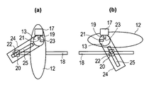
図1(a)及び(b)に示す実施の形態の4発ティルトウイング形態無人飛行機は、機体10と、機体10の前方(図1視左方)に、機体10の左右方向[図1(b)視上下方向]に突出して設けられた左右一対の前方主翼12、12(先端近くは省略して示す)と、機体10の後方に、機体10左右方向に突出して設けられた左右一対の後方主翼14、14(先端近くは省略して示す)とを備えている。一対の前方主翼12、12はそれぞれ1つずつの2つの電動プロペラ(図示せず)を有し、同様に、一対の後方主翼14、14はそれぞれ1つずつの2つの電動プロペラ(図示せず)を有する。
[First Embodiment]
The four-engine tilt wing type unmanned aerial vehicle of the embodiment shown in FIGS. 1A and 1B includes an
前方主翼12、12及び後方主翼14、14は、前進飛行角度と垂直飛行角度との間で、それぞれ前方主翼回動軸13及び後方主翼回動軸15を中心に回動する。前方主翼12、12及び後方主翼14、14は、前方主翼回動軸13及び後方主翼回動軸15にそれぞれ固定されており、前方主翼回動軸13及び後方主翼回動軸15はそれぞれ機体10に回動可能に支持されている。その結果、前方主翼12、12及び後方主翼14、14はそれぞれ、機体10について相対的に、前方主翼回動軸13及び後方主翼回動軸15を中心に回動することができる。
The front
前方主翼12、12を回動させるための前方主翼回動機構は、前方主翼12よりもさらに前方に配置された前方電動モータ16と、前方電動モータ16の駆動軸に固定されて後方に向かって延び、外周面にネジが切られているネジ部材である雄ネジ軸18と、内周面に雄ネジ軸18に螺合するネジが切られており、雄ネジ軸18の軸線回りの回動に従って雄ネジ軸18の軸方向に沿って直線移動するナット20と、ナット20から左右両方向に突出した2本の棒状であるカムフォロワ22、22と、カムフォロワ22、22それぞれを案内するための溝が長手方向に設けられた溝カム24、24とからなり、機体10に内蔵されている。溝カム24、24の一端は前方主翼12、12の回動軸13に固定されている。従って溝カム24、24の一端は、前方主翼12及び回動軸13と一体に回動する。
The front main wing rotating mechanism for rotating the front
同様に、後方主翼回動機構は後方電動モータ26と、前方に向かって延びる雄ネジ軸28と、雄ネジ軸28と螺合するナット30と、ナット30から突出した2本のカムフォロワ32、32と、カムフォロワ32、32をそれぞれ案内する溝カム34、34とからなり、溝カム34、34の一端は後方主翼14、14の回動軸13にそれぞれ固定されている。
Similarly, the rear main wing rotating mechanism includes a rear
各主翼回動機構には、各主翼の角度を前進飛行角度又は垂直飛行角度に固定するためのロック機構が付設されている。図2において、前方主翼12に固定された回動軸13には、溝カム24の一端が固定され、溝カム24の溝25はカムフォロワ22を案内する。回動軸13の上方の回動軸13の外周面に近接する位置に、ソレノイド17が機体10に固定されている。ソレノイド17は、プランジャ19が下方に向かって突出する姿勢で機体10に固定される。回動軸13の外周面には、プランジャ19がぴったり嵌まり込む形状及びサイズに形成された穴である垂直飛行角度用ロック穴21及び前進飛行角度用ロック穴23が穿設されており、それぞれプランジャ19が嵌まり込むことにより、前方主翼12を所定の角度にロックすることができる。すなわち図2(a)では、ソレノイド17のプランジャ19が垂直飛行角度用ロック穴21に嵌まり込むことにより前方主翼12が垂直飛行角度にロックされ、図2(b)では、ソレノイド17のプランジャ19が前進飛行角度用ロック穴23に嵌まり込むことにより前方主翼12が前進飛行角度にロックされている。ソレノイド17は非通電時にプランジャ19が突出する。
Each main wing rotating mechanism is provided with a lock mechanism for fixing the angle of each main wing to the forward flight angle or the vertical flight angle. In FIG. 2, one end of the
なお、上記のようなソレノイド17と回転軸に設けられたロック穴21,23との組み合わせによるロック機構と同様の構成に係るロック機構が、以下に述べる荷物保持搬出機構及び車輪移動機構にも設けられているが、説明は省略する。
A lock mechanism having the same structure as the lock mechanism formed by the combination of the
また図2(a)及び(b)より、主翼の回動する動作も明らかである。すなわち図2(a)に示されているように、ナット20が雄ネジ軸18の前端にあるときには、前方主翼12は垂直飛行角度をとっている。この状態から前方電動モータ16を駆動して雄ネジ軸18を回動させてナット20が雄ネジ軸18の後端に向かって移動すると、カムフォロワ22を案内する溝カム24が回動し、これに従って前方主翼12も図視反時計回り方向に回動して、図2(b)のような前進飛行角度に変化する。前方電動モータ16を反転させてナット29を図2(a)の位置に戻すと、前方主翼12も垂直飛行角度に戻される。
Also, from FIGS. 2A and 2B, the rotating motion of the main wing is also clear. That is, as shown in FIG. 2A, when the
電動プロペラ、前方電動モータ16及び後方電動モータ26の電源となる蓄電器は、前方主翼12、12及び後方主翼14、14に内蔵された扁平型のリチウムイオン電池である(図示せず)。機体10の前方主翼回動機構と後方主翼回動機構との間には、荷物Cを収納する荷物室36が構成されている。
The electric storage device serving as a power source for the electric propeller, the front
本実施の形態の4発ティルトウィング形態無人飛行機は、前方主翼12、12及び後方主翼14、14が前進飛行角度にあるときには、荷物Cを荷物室36内に保持し、前方主翼12、12及び後方主翼14、14が垂直飛行角度に変化した後に、荷物Cを荷物室36から搬出する搬出動作をする荷物保持搬出機構を機体10内に備えている。
The four-engine tilt wing type unmanned aerial vehicle of the present embodiment holds the luggage C in the
荷物保持搬出機構は、前方電動モータ16及び後方電動モータ26を駆動源としている。荷物保持搬出機構は、左右一対の前方クランク38、38と、前方クランク軸40と、左右一対の後方クランク42、42と、後方クランク軸44と、従動プーリ46と、タイミングベルト48と、駆動プーリ50と、カム52とから構成される。左右一対の前方クランク38、38は、前方主翼12、12の下方に配置され、前後方向に延びて荷物Cの前端近くを上面で保持する自由端側の水平部分38Aと、水平部分38Aの前端から上方に延びて上端近くがカムフォロワ32、32に当接する固定端側の垂直部分38Bとからなり、図1(a)で見た状態でL字形を呈している。前方クランク軸40は、右方向に延びて、両端が一対の前方クランク38,38の垂直部分の中間に固定されており、一対の前方クランク38,38を機体10に対して軸回りに回動可能に支持する。左右一対の後方クランク42、42は、後方主翼14、14の下方且つやや前方に配置され、前後方向に延びて荷物Cの後端近くを上面で保持する自由端側の水平部分42Aと、水平部分42Aの後端から上方に延びる固定端側の垂直部分42Bとからなり、図1(a)で見た状態でL字型を呈している。後方クランク軸44は、左右方向に延びて、一対の後方クランク42、42の上端が固定されており、一対の後方クランク42、42を機体10に対して軸回りに回動可能に支持する。そして荷物保持搬出機構は、後方クランク軸44と軸を共通にして後方クランク軸44に固定された従動プーリ46と、従動プーリ46に架け渡されたタイミングベルト48と、タイミングベルト48がクロス掛けされた駆動プーリ50と、駆動プーリ50に固定され、先端近くがカムフォロワ32に当接するカム52とを備えている。
The luggage holding and unloading mechanism uses the front
前方クランク38、38及び後方クランク42、42はそれぞれ、前方クランク軸40及び後方クランク軸44を中心に回動して、荷物Cを荷物室36内に保持する保持角度と、荷物Cを荷物室36から搬出する搬出角度との間で角度が変化する。前方クランク38、38及び後方クランク42、42はそれぞれ、荷物Cを荷物室36内に保持する保持角度に向かう方向に回動するように付勢されており(付勢機構は図示していない)、すなわち前方クランク38は前方クランク軸40を中心に図1(a)で見て反時計回り方向に回動するように、逆に後方クランク42、42は後方クランク軸44を中心に図1(a)で見て時計回り方向に回動するように、それぞれ図示しない付勢機構により付勢されている。
The front cranks 38, 38 and the rear cranks 42, 42 rotate about the
図3(a)は図1と同じ状態の荷物保持搬出機構を示している。ナット20、30が雄ネジ軸18、28の前端近くに位置しているとき、主翼12(及び14)は垂直飛行角度にあり、荷物室36内の荷物Cは前方クランク38及び後方クランク42により保持されている。保持状態は、図3(b)に示すように、電動モータ16、26が雄ネジ軸18、28を回動させてナット20、30が後方に向かって移動し、雄ネジ軸18、28の前後方向の中心近くまで達して、主翼12(及び14)が前進飛行角度に移行しても未だ維持される。この状態からさらにナット20、30が移動すると、カムフォロワ22、32がそれぞれ前方クランク38の上端及びカム52にだんだんと近付く。図3(c)に示すように、ナット20、30が雄ネジ軸18、28の後端近くに達した状態では、前方クランク38はカムフォロワ22に押されて前方クランク軸40を中心に図視の時計回り方向に回動し、その自由端側の水平部分が荷物Cの下面から外れて、搬出状態に変化する。また後方クランク42は、カム52の回動により、駆動プーリ50が図視の時計回りに回動し、クロス掛けされたタイミングベルト48が走行して、従動プーリ46が回動して、後方クランク42が後方クランク軸44を中心に図視時計回り方向に回動する。その結果、自由端側の水平部分が荷物Cの下面から外れて、搬出状態に変化する。このとき、主翼12(及び14)は、図3(c)に示すように前進飛行角度を超えて回動するが、特に問題はない。
FIG. 3A shows the load holding/unloading mechanism in the same state as in FIG. When the nuts 20 and 30 are located near the front ends of the
搬出状態から保持状態に戻す際には、雄ネジ軸18、28を逆回転させてナット20、30を前方に向かう方向に移動させると、カムフォロワ22、32の押圧が外れて前方クランク38及び後方クランク42は付勢機構による付勢により回動し、図3(b)及び(a)の保持状態に復帰することができる。
When returning from the carrying-out state to the holding state, when the
このように、本実施の形態の4発ティルトウィング形態無人飛行機の荷物保持搬出機構は、飛行中は荷物Cを保持し、着陸後は電動モータ16、26を駆動して荷物Cを自動的に搬出することができる。すなわち第1の実施の形態の荷物保持搬出機構は、前方電動モータ16及び後方電動モータ26を駆動源として搬出動作をするように構成されて荷物の搬出を自動化することができる。また荷物保持搬出機構のための駆動源を別個に用意する必要がないので、部品点数を減らして、無人飛行機の重量を軽くすることができる。その結果、飛行距離を伸ばすことができる。
As described above, the luggage holding and carrying-out mechanism of the 4-tilt-wing unmanned airplane of the present embodiment holds the luggage C during the flight, and automatically drives the luggage C by driving the
さらにまた、この荷物保持搬出機構の前方クランク38及び後方クランク42は、図3(a)に示すような垂直飛行時に搬出動作を開始するのではなく、着陸するまで自由端において荷物Cを支え、前方電動モータ16及び後方電動モータ26が作動して図3(c)のように搬出動作が開始されると固定端の前方クランク軸40、後方クランク軸44を中心にして互いに離れる方向に回動するように構成され、簡単な構造で荷物保持搬出機構を構成することができる。
Furthermore, the front crank 38 and the rear crank 42 of this load holding and unloading mechanism do not start the unloading operation during vertical flight as shown in FIG. 3A, but support the load C at the free end until landing, When the front
さらに、図1(a)に示すように、本実施の形態の4発ティルトウィング形態無人飛行機は、機体10内の前方主翼12、12及び後方主翼14、14の下方の位置に、前後それぞれの車輪移動機構を備えている。車輪移動機構は、前方主翼12、12及び後方主翼14、14が前進飛行角度にあるときには、機体10の内部に、左右一対の前方車輪54、54及び左右一対の後方車輪56、56の4つの車輪を収納し、前方主翼12、12及び後方主翼14、14が前進飛行角度から垂直飛行角度に変化するときに機体10の外部に前方車輪54、54及び後方車輪56、56を引き出すように動作し、前方主翼12、12及び後方主翼14、14が垂直飛行角度から前進飛行角度に変化するときに機体10の内部に前方車輪54、54及び後方車輪56、56を収納するように動作する。
Further, as shown in FIG. 1( a ), the four-engine tilt-wing unmanned aerial vehicle of the present embodiment has front and rear
本実施の形態における車輪移動機構は、前方電動モータ16及び後方電動モータ26を駆動源として動作する。このようにすると車輪移動機構のための駆動源を別個に用意する必要がないので、部品点数を減らして、無人飛行機の重量を軽くすることができる。その結果、飛行距離を伸ばすことができる。
The wheel moving mechanism in the present embodiment operates using the front
前方車輪54、54及び後方車輪56、56はそれぞれ左右一対の前方脚58、58及び後方脚60、60の下端に取り付けられており、前方脚58、58及び後方脚60、60の各上端はそれぞれ前方脚軸62及び後方脚軸64に固定されている。前方脚軸62及び後方脚軸64は、機体10に対して軸回りに回動可能であり、従って前方脚58、58及び後方脚60、60も前方脚軸62及び後方脚軸64を中心に、それぞれ角度を変えることができる。
The
前方脚軸62及び後方脚軸64にはそれぞれリンク66の下端が接続されている。前方脚軸62及び後方脚軸64とリンク66との間には、前述した機体10と各軸との間のロック機構(第1のロック機構)とは別に、前方脚軸62及び後方脚軸64とリンク66との間の回動をロックし又はロック解除する第2のロック機構が設けられており、このロック機構を制御することにより、前方脚軸62及び後方脚軸64とリンク66とをロックした状態か、あるいは相互に自由に回動できるロックを解除した状態か、いずれかの状態を選択することができる。
The lower ends of
また前方脚軸62及び後方脚軸64には、図視の状態で反時計回り方向、すなわち前方車輪54、後方車輪56を機体10の外部に引き出す方向に回転するように付勢する付勢機構が設けられている(図示せず)。リンク66の他端は溝カム68の図1(a)において右端に相互に回動可能に接続されている。溝カム68には長手方向に長孔70が設けられ、長孔70をカムフォロワ22、32が貫通している。カムフォロワ22、32はナット20、30と一体に雄ネジ軸18、28の軸線に沿う方向に移動するので、前方電動モータ16及び後方電動モータ26を駆動することにより、前方車輪54、後方車輪56の引き出し及び収納を行うことができる。
A biasing mechanism that biases the
次に車輪移動機構の作用について、図4を参照しつつ説明する。図4(a),(b)及び(c)において、前述の第2のロック機構は、リンク66に固定されたソレノイド72と、前方脚軸62及び後方脚軸64の外周面に穿設され、ソレノイド72から突出するプランジャ74が嵌まり込むロック穴76とからなる。図4(a)及び(b)において、ソレノイド72のプランジャ74はロック穴76に嵌まり込んでおり、前方脚軸62とリンク66とは相互に固定されて、前方脚58とリンク66とがほぼ直線上に並んでいる。これに対して図4(c)ではソレノイド72のプランジャ74は引っ込められており、前方脚軸62とリンク66とのロックが解除されて、相互に回動可能な状態である。図4(c)においてはリンク66と前方脚58とは直線を構成せず、前方脚軸62において折れ曲がった形状を呈している。
Next, the operation of the wheel moving mechanism will be described with reference to FIG. 4(a), (b) and (c), the above-mentioned second locking mechanism is provided in the
図4(a)(b)及び(c)それぞれの状態を確認すると、図4(a)では、ナット20が雄ネジ軸18の前端近くにあり、前方主翼12が垂直飛行角度を採っている。このとき車輪移動機構の溝カム68は、長孔70が雄ネジ軸18に重なる姿勢である。図4(a)の位置からナット20が後方へ移動していくと、長孔70は雄ネジ軸18の約半分の長さなので、カムフォロワ22が長孔70の後端に突き当たり、溝カム68を押して、前方脚軸62が時計回り方向に回動し、図4(b)のように前方車輪54が機体10内に収納される。図4(a)の位置から、第2のロック機構を解除、すなわちソレノイド72のプランジャ74を引っ込めた状態で、ナット20を移動させると、前方脚軸62はリンク66の回動に拘わらず車輪が引き出された状態が維持される。なお図4(a)から図4(b)に移行する際には、前方脚軸62を機体10に対して固定する第1のロック機構は解除されており、逆に図4(a)から図4(c)への移行の間は、第1のロック機構は前方脚軸62をロックして、前方車輪54が無人飛行機を支持できるようにしていることは言うまでもない。
4(a), 4(b) and 4(c), the
なお、車輪移動機構における図2に示した機構と同様の第1のロック機構は、前方車輪54、後方車輪56が収納位置にあるとき及び引き出し位置にあるときに、前方車輪54、後方車輪56を支持する前方脚58、後方脚60を固定状態にするストッパ機構として作用する。第1のロック機構を構成するソレノイドは、非通電時にプランジャが突出してロック状態を維持するので、その間は電力を使用するこなく、固定状態を維持でき、これにより節電効果が得られる。もしも前方脚58、後方脚60に大きな荷重がかかる可能性のある場合には、第1のロック機構とは別のより堅牢な機械的なストッパ機構が追加的に設けられてもよく、又は第1のロック機構の機能を代行するようにしてもよい。
It should be noted that the first lock mechanism similar to the mechanism shown in FIG. 2 in the wheel moving mechanism has a
第1の実施の形態の4発ティルトウィング形態無人飛行機は、主翼12、14が前進飛行角度にロックされ、前方クランク38、後方クランク42が荷物保持状態にロックされ、前方車輪54、後方車輪56が収納状態でロックされて目的地まで前進飛行し[図2(b)]、目的地の上空で垂直飛行に切り替わるべく、ナット20、30が雄ネジ軸18、28の中間から前端近くに移動し、主翼12、14が垂直飛行角度に変化すると同時に、前方脚軸62及び後方脚軸64の第1のロックが解除され、前方車輪54、後方車輪56が機体10から引き出され、前方脚軸62及び後方脚軸64は引き出された位置で再度第1のロックがかかり、第2のロックは解除される[図1(a)、図2(a)、図4(b)]。
In the four-engine tilt-wing type unmanned aerial vehicle of the first embodiment, the
ナット20、30が雄ネジ軸18、28の後端近くまで移動すると、前方クランク38及び後方クランク42の自由端が相互に離反して、荷物Cの搬出状態となり、荷物Cが荷物室36から搬出される[図3(c)]。このとき前方脚軸62及び後方脚軸64の第2のロックは解除されているので、前方車輪54、後方車輪56は引き出されて機体10を支持したままである[図4(c)]。
When the nuts 20 and 30 move to near the rear ends of the
次にナット20、30が雄ネジ軸18、28の前端近くに戻されるが、このとき前方クランク38及び後方クランク42は付勢機構により荷物保持状態に戻されてロックされ[図3(a)]、前方車輪54、後方車輪56は第1のロックがなされたままで図4(a)の状態に戻って第2のロック機構がロックされる。同時に前方主翼12、後方主翼14が垂直飛行角度に戻ってロックされて[図1(a)、図2(a)]、適当な高度まで達したら前方主翼12、後方主翼14のロックが解除されて、ナット20、30が雄ネジ軸18、28の中間に移動して、前進飛行角度でロックされ、前進飛行する[図2(b)]。同時に、前方車輪54、後方車輪56も前方脚軸62、後方脚軸64の第1のロックを解除して、付勢によって機体10内に収納される。
Next, the nuts 20 and 30 are returned near the front ends of the
以上説明したように、第1の実施の形態の4発ティルトウイング形態の無人飛行機は、機体10内に、前方主翼12よりも前方側に前方電動モータ16を配置し、後方主翼14よりも後方側に後方電動モータ26を配置し、前方主翼回動機構と後方主翼回動機構との間に荷物Cを収納する荷物室36を構成した。
As described above, in the unmanned aerial vehicle of the four-engine tilt wing mode of the first embodiment, the front
このような構成により、荷物Cを機体10の外部にできる限り露出させることなく、荷物室36を機体10内に構成することができるので、前方主翼12及び後方主翼14を前進飛行角度にした状態で、空気抵抗を最小に抑えつつ荷物Cを搬送することができる。
With such a configuration, the
なお他の実施の形態は、電動プロペラが前方主翼に左右2発設けられ、後方主翼には電動プロペラが設けられていない2発ティルトウイング形態無人飛行機であり、後方主翼回動機構が存在せず、前方主翼回動機構よりも後方に荷物室が構成されている以外は、第1の実施の形態と同様の構成を有する。 Still another embodiment is a two-engine tilt wing type unmanned airplane in which two electric propellers are provided on the front main wing on the left and right, and no electric propeller is provided on the rear main wing, and there is no rear main wing rotation mechanism. The structure is the same as that of the first embodiment except that the luggage compartment is formed behind the front main wing rotating mechanism.
このような実施の形態においても、荷物を機体の外部をあまり露出させることなく、荷物室を機体内に構成することができるので、前方主翼を前進飛行角度にした状態で、空気抵抗を小さい状態にして荷物を搬送することができる。 Even in such an embodiment, since the luggage compartment can be configured in the body without exposing the luggage to the outside of the fuselage, the air resistance is small when the front main wing is at the forward flight angle. You can then carry your luggage.
[第2の実施の形態]
第2の実施の形態の4発ティルトウィング形態無人飛行機の主要部の構成を図5(a)及び(b)に示す。第2の実施の形態の4発ティルトウィング形態無人飛行機は、前方主翼及び後方主翼(図示せず)が垂直飛行角度にあるときに、斜め下方に延伸して荷物Cが自重で滑り落ちるスロープ80を形成するように構成された荷物保持搬出機構を有している。
[Second Embodiment]
5A and 5B show the configuration of the main part of a four-engine tilt wing type unmanned aerial vehicle according to the second embodiment. The four-engine tilt wing type unmanned aerial vehicle of the second embodiment has a
機体82の荷物室84の底面は、荷物Cを載置したまま延伸可能なスロープ80から構成されている。スロープ80は、第1の実施の形態と同様の機構により後方主翼の角度を変えるための駆動源となる後方電動モータ86により動作する。すなわち、後方電動モータ86の駆動軸88に取り付けられたマイクロクラッチ付のプーリ90に巻き付けられたワイヤを巻き出すことによりスロープ80を延ばして荷物Cをスロープ80の先端から地面やベランダ等に搬出することができる。スロープ80を縮める場合には、後方電動モータ86を逆回転して、マイクロクラッチを繋いだプーリ90にワイヤを巻き取らせる。スロープ80が荷物室84の底面に収納されたら、プーリ90のマイクロクラッチを切った上で後方電動モータ86を作動させて、垂直飛行角度にロックされていた主翼の角度を変化させ、前進飛行に移行する。
The bottom surface of the
このような荷物保持搬出機構を有する第2の実施の形態の4発ティルトウィング形態無人飛行機によると、例えばマンションのベランダのような高所に荷物置き場を設定しても、スロープ80を利用して荷物Cをベランダに搬出することが可能になる。
According to the 4-tilt-wing unmanned aerial vehicle of the second embodiment having such a luggage holding and carrying-out mechanism, even if the luggage storage is set at a high place such as a balcony of an apartment, the
[第3の実施の形態]
第3の実施の形態の4発ティルトウィング形態無人飛行機の要部の構成を図6に示す。第3の実施の形態の4発ティルトウィング形態無人飛行機の荷物保持搬出機構は、前方主翼及び後方主翼が垂直飛行角度にあるときに、斜め下方に延びるかまたは斜め上方に縮んで荷物置き場にある荷物を引き上げるクレーン92を有する。
[Third Embodiment]
FIG. 6 shows a configuration of a main part of a four-engine tilt wing type unmanned aerial vehicle according to the third embodiment. The luggage holding and carrying-out mechanism of the four-engine tilt wing type unmanned aerial vehicle of the third embodiment extends obliquely downward or contracts obliquely upward and is in the luggage storage area when the front and rear wings are at vertical flight angles. It has a
クレーン92は、第2の実施の形態におけるスロープ80と同様に、後方主翼の角度を変えるための駆動源である後方電動モータの駆動軸に取り付けられたマイクロクラッチ付のプーリ(図示せず)を利用して伸縮させることができる。
Like the
クレーン92の角度は、やはり後方電動モータの駆動軸を回動することにより変更可能である。また第3の実施の形態では、荷物Cを機体94よりも前方に吊り下げたときに、バランサー替わりに、4発のうちの2発の後方プロペラ96の向きを上下逆にして下向きの力を発生させてバランスを取るようにする。このとき機体94は前方プロペラ98の揚力によってのみ浮揚されている。
The angle of the
荷物保持搬出機構をこのように構成すると、マンションのベランダ等の高所を荷物積み場または荷物置き場として、クレーン92を利用して荷物Cを搬入及び搬出することが可能になる。
With such a configuration of the luggage holding and carrying-out mechanism, it is possible to carry in and carry out the luggage C using the
図7は第3の実施の形態のクレーンの先に備えられた荷物自動分離機構を示す。図7(a)に示すように、クレーン92の先から延びる糸100は4つに枝分かれしており、そのうち1本に結束具102、残り3本に鉄球104が接続されており、図7(b)及び(c)に示すように、荷物Cの底面において結束具102と鉄球104とが結束されることにより、荷物Cが保持されている。結束具102は、図7(d)に示すように正方形の基板106と、基板106から延びる4つの側面のうちの3つに中心にスリットが設けられ、スリットが設けられていない側面の中心に糸100が接続された四角柱状の鉄球係止部108と、鉄球係止部108の端縁と荷物置き場の面との間に、少なくとも鉄球104が通過可能なスペースを空けるための支柱110とからなる。
FIG. 7 shows an automatic load separating mechanism provided at the tip of the crane according to the third embodiment. As shown in FIG. 7(a), the
図7(d)に示すように、結束具102は、底面が正方形の直方体状である荷物Cの底面において、3つの鉄球104を鉄球係止部108の3つのスリットそれぞれに係止することにより、図7(b)のような4本に枝分かれした糸100による吊り下げを実現することができる。荷物Cを支柱110で支持して荷物置き場の面に載置して、さらに糸100を弛緩させると、鉄球係止部108の3つのスリットから鉄球104が外れて、鉄球係止部108の端縁と荷物置き場の面との間を通って鉄球係止部108の外側へ抜けることが可能となり、4本の枝分かれした糸100相互の結束が解かれる。この状態で、糸100を上昇させると荷物Cの底面から結束具102及び鉄球104が引き出されて、荷物Cのみが荷物置き場に残される。支柱110の先端の面は、荷物Cを安定させるために、平板を備える等面積を拡大するようにしてもよい。
As shown in FIG. 7D, in the
上記第2の実施の形態及び第3の実施の形態では、荷物保持搬出機構が、主翼を回動させる電動モータにより、スロープ80及びクレーン92を駆動しているが、スロープ80及びクレーン92を専用の電動源によって駆動してもよいのは勿論である。専用の電動源を設ければ、上記第2の実施の形態及び第3の実施の形態において、スロープ80及びクレーン92を伸ばすと、梃子原理が働いて、荷物の重量が重い場合には、機体の姿勢が不安定になる場合がある。このような場合には、スロープ80及びクレーン92から遠い側に位置する電動プロペラの回転を反転させれば、機体を安定化させることができる。
In the second and third embodiments described above, the luggage holding/unloading mechanism drives the
なお上記のスロープ、クレーン及び車輪は、2以上電動プロペラが前方主翼にだけ設けられている場合にも、当然にして設けることができる。 The above slope, crane and wheels can naturally be provided even when two or more electric propellers are provided only on the front main wing.
以上のように本発明によれば、蓄電器を駆動電源とする場合において、荷物を搬送するのに適したティルトウイング形態無人飛行機を提供することができる。 As described above, according to the present invention, it is possible to provide a tilt wing type unmanned aerial vehicle which is suitable for carrying luggage when a power storage device is used as a driving power source.
10 機体
12 前方主翼
13 前方主翼回転軸
14 後方主翼
15 後方主翼回転軸
16 前方電動モータ
18、28 雄ネジ軸
20、30 ナット
22、32 カムフォロワ
24、34 溝カム
26 後方電動モータ
36 荷物室
38 前方クランク
40 前方クランク軸
42 後方クランク
44 後方クランク軸
46 従動プーリ
48 タイミングベルト
50 駆動プーリ
52 カム
54 前方車輪
56 後方車輪
58 前方車輪脚
60 後方車輪脚
62 前方車輪軸
64 後方車輪軸
66 リンク
68 溝カム
C 荷物
10
Claims (14)
前記機体の前方に設けられた2以上の電動プロペラを有する前方主翼と、
前記機体の後方に設けられた後方主翼と、
前記前方主翼を前進飛行角度と垂直飛行角度との間で回動させる、前方電動源を備えた前方主翼回動機構と、
前記電動プロペラ及び前記前方電動源の電源となる蓄電器を備えたティルトウイング形態無人飛行機であって、
前記機体内には、前記前方主翼回動機構よりも後方に荷物を収納する荷物室が構成されており、
前記後方主翼に2以上電動プロペラをさらに備え、
前記後方主翼を前進飛行角度と垂直飛行角度との間で回動させる、後方電動源を備えた後方主翼回動機構をさらに備え、
前記前方主翼回動機構と前記後方主翼回動機構との間に前記荷物室が構成されており、
前記機体内には、前記前方主翼よりも前方側に前記前方電動源が配置され、前記後方主翼よりも後方側に前記後方電動源が配置されていることを特徴とするティルトウイング形態無人飛行機。 The aircraft,
A front wing having two or more electric propellers provided in front of the airframe;
A rear main wing provided at the rear of the aircraft,
A front main wing rotation mechanism including a front electric power source, which rotates the front main wing between a forward flight angle and a vertical flight angle;
A tilt wing type unmanned aerial vehicle comprising a power storage device serving as a power source for the electric propeller and the front electric power source,
Inside the fuselage, a luggage compartment for storing luggage is formed behind the front main wing rotation mechanism,
The rear main wing further includes two or more electric propellers,
Further comprising a rear main wing rotation mechanism having a rear electric power source for rotating the rear main wing between a forward flight angle and a vertical flight angle,
The luggage compartment is configured between the front main wing rotation mechanism and the rear main wing rotation mechanism,
A tilt wing type unmanned aerial vehicle, wherein the front electric power source is arranged in front of the front main wing and the rear electric power source is arranged in rear of the rear main wing in the body.
前記機体の前方に設けられた2以上の電動プロペラを有する前方主翼と、
前記機体の後方に設けられた後方主翼と、
前記前方主翼を前進飛行角度と垂直飛行角度との間で回動させる、前方電動源を備えた前方主翼回動機構と、
前記電動プロペラ及び前記前方電動源の電源となる蓄電器を備えたティルトウイング形態無人飛行機であって、
前記機体内には、前記前方主翼回動機構よりも後方に荷物を収納する荷物室が構成されており、
前記後方主翼に2以上電動プロペラをさらに備え、
前記後方主翼を前進飛行角度と垂直飛行角度との間で回動させる、後方電動源を備えた後方主翼回動機構をさらに備え、
前記前方主翼回動機構と前記後方主翼回動機構との間に前記荷物室が構成されており、
前記前方主翼回動機構及び前記後方主翼回動機構は、それぞれ回転モータによって回転駆動されるネジ部材と、該ネジ部材に螺合されたナット部材と、前記ネジ部材の回転によって直線移動する前記ナット部材に回動可能に設けられたスライダと、前記スライダがスライド可能に嵌合されるスリットを備えて一端が回動可能に固定された回動リンクとからなり、前記回動リンクの前記一端の回転を利用して主翼回動軸を回動させるように構成されているティルトウイング形態無人飛行機。 The aircraft,
A front wing having two or more electric propellers provided in front of the airframe;
A rear main wing provided at the rear of the aircraft,
A front main wing rotating mechanism including a front electric power source, which rotates the front main wing between a forward flight angle and a vertical flight angle,
A tilt wing type unmanned aerial vehicle comprising a power storage device serving as a power source for the electric propeller and the front electric power source,
Inside the fuselage, a luggage compartment for storing luggage is formed behind the front main wing rotation mechanism,
The rear main wing further includes two or more electric propellers,
Further comprising a rear main wing rotation mechanism having a rear electric power source for rotating the rear main wing between a forward flight angle and a vertical flight angle,
The luggage compartment is configured between the front main wing rotation mechanism and the rear main wing rotation mechanism,
Each of the front main wing rotation mechanism and the rear main wing rotation mechanism is a screw member that is rotationally driven by a rotation motor, a nut member that is screwed into the screw member, and the nut that is linearly moved by rotation of the screw member. The slider is rotatably provided on the member, and the rotary link is provided with a slit into which the slider is slidably fitted and one end of which is rotatably fixed. A tilt wing type unmanned aerial vehicle configured to rotate the main wing rotation axis using rotation.
前記機体の前方に設けられた2以上の電動プロペラを有する前方主翼と、
前記機体の後方に設けられた後方主翼と、
前記前方主翼を前進飛行角度と垂直飛行角度との間で回動させる、前方電動源を備えた前方主翼回動機構と、
前記電動プロペラ及び前記前方電動源の電源となる蓄電器を備えたティルトウイング形態無人飛行機であって、
前記機体内には、前記前方主翼回動機構よりも後方に荷物を収納する荷物室が構成されており、
前記後方主翼に2以上電動プロペラをさらに備え、
前記後方主翼を前進飛行角度と垂直飛行角度との間で回動させる、後方電動源を備えた後方主翼回動機構をさらに備え、
前記前方主翼回動機構と前記後方主翼回動機構との間に前記荷物室が構成されており、
着陸して前記電動プロペラの駆動を停止した後に、前記前方主翼回動機構及び前記後方主翼回動機構により前記前方主翼及び前記後方主翼をさらに回動させると、前記荷物を前記荷物室から搬出する搬出動作をする荷物保持搬出機構を前記機体内に備え、
前記荷物保持搬出機構は、前記前方電動源及び前記後方電動源を駆動源として前記搬出動作をするように構成されているティルトウイング形態無人飛行機。 The aircraft,
A front wing having two or more electric propellers provided in front of the airframe;
A rear main wing provided at the rear of the aircraft,
A front main wing rotating mechanism including a front electric power source, which rotates the front main wing between a forward flight angle and a vertical flight angle,
A tilt wing type unmanned aerial vehicle comprising a power storage device serving as a power source for the electric propeller and the front electric power source,
Inside the fuselage, a luggage compartment for storing luggage is formed behind the front main wing rotation mechanism,
The rear main wing further includes two or more electric propellers,
Further comprising a rear main wing rotation mechanism having a rear electric power source for rotating the rear main wing between a forward flight angle and a vertical flight angle,
The luggage compartment is configured between the front main wing rotation mechanism and the rear main wing rotation mechanism,
After landing and stopping the drive of the electric propeller, when the front main wing and the rear main wing rotating mechanism further rotate the front main wing and the rear main wing, the luggage is unloaded from the luggage compartment. A loading and unloading mechanism for carrying out an unloading operation is provided in the body,
The tilt wing type unmanned aerial vehicle, wherein the luggage holding and carrying-out mechanism is configured to perform the carrying-out operation by using the front electric power source and the rear electric power source as driving sources.
前記前方クランク及び前記後方クランクは、前記搬出動作を開始する前までは自由端において前記荷物を支え、前記搬出動作が開始されると固定端を中心にして互いに離れる方向に回動するように構成されている請求項3に記載のティルトウイング形態無人飛行機。 The luggage holding and discharging mechanism includes a front crank driven by the front electric power source and a rear crank driven by the rear electric power source,
The front crank and the rear crank are configured to support the load at their free ends before the carrying-out operation is started, and to rotate away from each other around the fixed end when the carrying-out operation is started. The tilt wing unmanned aerial vehicle according to claim 3.
前記機体の前方に設けられた2以上の電動プロペラを有する前方主翼と、
前記機体の後方に設けられた後方主翼と、
前記前方主翼を前進飛行角度と垂直飛行角度との間で回動させる、前方電動源を備えた前方主翼回動機構と、
前記電動プロペラ及び前記前方電動源の電源となる蓄電器を備えたティルトウイング形態無人飛行機であって、
前記機体内には、前記前方主翼回動機構よりも後方に荷物を収納する荷物室が構成されており、
前記荷物を前記荷物室から搬出する搬出動作をする荷物保持搬出機構を前記機体内に備え、
前記荷物保持搬出機構は、前記前方主翼及び前記後方主翼が前記垂直飛行角度にあるときに、斜め下方に延伸して前記荷物が自重で滑り落ちるスロープを形成するように構成されているティルトウイング形態無人飛行機。 The aircraft,
A front wing having two or more electric propellers provided in front of the airframe;
A rear main wing provided at the rear of the aircraft,
A front main wing rotating mechanism including a front electric power source, which rotates the front main wing between a forward flight angle and a vertical flight angle,
A tilt wing type unmanned aerial vehicle comprising a power storage device serving as a power source for the electric propeller and the front electric power source,
Inside the fuselage, a luggage compartment for storing luggage is formed behind the front main wing rotation mechanism,
A luggage holding and unloading mechanism for carrying out the luggage from the luggage compartment is provided in the body,
The luggage holding/unloading mechanism is configured to form a slope that extends obliquely downward and the luggage slides down by its own weight when the front main wing and the rear main wing are at the vertical flight angle. airplane.
前記機体の前方に設けられた2以上の電動プロペラを有する前方主翼と、
前記機体の後方に設けられた後方主翼と、
前記前方主翼を前進飛行角度と垂直飛行角度との間で回動させる、前方電動源を備えた前方主翼回動機構と、
前記電動プロペラ及び前記前方電動源の電源となる蓄電器を備えたティルトウイング形態無人飛行機であって、
前記機体内には、前記前方主翼回動機構よりも後方に荷物を収納する荷物室が構成されており、
前記後方主翼に2以上電動プロペラをさらに備え、
前記後方主翼を前進飛行角度と垂直飛行角度との間で回動させる、後方電動源を備えた後方主翼回動機構をさらに備え、
前記前方主翼回動機構と前記後方主翼回動機構との間に前記荷物室が構成されており、
前記荷物を前記荷物室から搬出する搬出動作をする荷物保持搬出機構を前記機体内に備え、
前記荷物保持搬出機構は、前記前方主翼及び前記後方主翼が前記垂直飛行角度にあるときに、斜め下方に延びるかまたは斜め上方に縮んで荷物置き場にある前記荷物を引き上げるクレーン機能を有しているティルトウイング形態無人飛行機。 The aircraft,
A front wing having two or more electric propellers provided in front of the airframe;
A rear main wing provided at the rear of the aircraft,
A front main wing rotating mechanism including a front electric power source, which rotates the front main wing between a forward flight angle and a vertical flight angle,
A tilt wing type unmanned aerial vehicle comprising a power storage device serving as a power source for the electric propeller and the front electric power source,
Inside the fuselage, a luggage compartment for storing luggage is formed behind the front main wing rotation mechanism,
The rear main wing further includes two or more electric propellers,
Further comprising a rear main wing rotation mechanism having a rear electric power source for rotating the rear main wing between a forward flight angle and a vertical flight angle,
The luggage compartment is configured between the front main wing rotation mechanism and the rear main wing rotation mechanism,
A luggage holding and unloading mechanism for carrying out the luggage from the luggage compartment is provided in the body,
The luggage holding/unloading mechanism has a crane function of pulling up the luggage in the luggage storage area by extending diagonally downward or contracting diagonally upward when the front main wing and the rear main wing are at the vertical flight angle. Tilt wing form Unmanned aerial vehicle.
前記荷物保持搬出機構が動作中においては、前記機体の姿勢を安定化させるように、前記荷物が位置する側とは反対側に位置する前記電動プロペラが回転を反転することを特徴とする請求項6または7に記載のティルトウイング形態無人飛行機。 The luggage holding and discharging mechanism is configured to be driven by a dedicated electric power source,
The electric propeller located on the side opposite to the side on which the luggage is located reverses its rotation so as to stabilize the attitude of the machine body when the luggage holding and carrying-out mechanism is in operation. The tilt wing type unmanned aerial vehicle according to 6 or 7.
前記機体の前方に設けられた2以上の電動プロペラを有する前方主翼と、
前記機体の後方に設けられた後方主翼と、
前記前方主翼を前進飛行角度と垂直飛行角度との間で回動させる、前方電動源を備えた前方主翼回動機構と、
前記電動プロペラ及び前記前方電動源の電源となる蓄電器を備えたティルトウイング形態無人飛行機であって、
前記機体内には、前記前方主翼回動機構よりも後方に荷物を収納する荷物室が構成されており、
前記後方主翼に2以上電動プロペラをさらに備え、
前記後方主翼を前進飛行角度と垂直飛行角度との間で回動させる、後方電動源を備えた後方主翼回動機構をさらに備え、
前記前方主翼回動機構と前記後方主翼回動機構との間に前記荷物室が構成されており、
前記機体内には、前記前方主翼及び前記後方主翼が前記前進飛行角度にあるときには、前記機体の内部に3つ以上の車輪を収納し、前記前方主翼及び前記後方主翼が前記前進飛行角度から前記垂直飛行角度に変化するときに前記機体の外部に前記3つ以上の車輪を引き出すように動作し、前記前方主翼及び前記後方主翼が前記垂直飛行角度から前記前進飛行角度に変化するときに前記機体の内部に前記3つ以上の車輪を収納するように動作する車輪移動機構を備えており、
前記車輪移動機構は、前記前方電動源及び前記後方電動源を駆動源として動作するように構成されているティルトウイング形態無人飛行機。 The aircraft,
A front wing having two or more electric propellers provided in front of the airframe;
A rear main wing provided at the rear of the aircraft,
A front main wing rotating mechanism including a front electric power source, which rotates the front main wing between a forward flight angle and a vertical flight angle,
A tilt wing type unmanned aerial vehicle comprising a power storage device serving as a power source for the electric propeller and the front electric power source,
Inside the fuselage, a luggage compartment for storing luggage is formed behind the front main wing rotation mechanism,
The rear main wing further includes two or more electric propellers,
Further comprising a rear main wing rotation mechanism having a rear electric power source for rotating the rear main wing between a forward flight angle and a vertical flight angle,
The luggage compartment is configured between the front main wing rotation mechanism and the rear main wing rotation mechanism,
When the front main wing and the rear main wing are at the forward flight angle in the body, three or more wheels are housed inside the body, and the front main wing and the rear main wing are located at the forward flight angle from the forward flight angle. The fuselage operates to draw the three or more wheels out of the airframe when changing to a vertical flight angle, and the airframe when the front and rear wings change from the vertical flight angle to the forward flight angle. Is equipped with a wheel moving mechanism that operates so as to house the three or more wheels,
The tilt wing type unmanned aerial vehicle, wherein the wheel moving mechanism is configured to operate using the front electric power source and the rear electric power source as driving sources.
前記機体の前方に設けられた2以上の電動プロペラを有する前方主翼と、
前記機体の後方に設けられた後方主翼と、
前記前方主翼を前進飛行角度と垂直飛行角度との間で回動させる、前方電動源を備えた前方主翼回動機構と、
前記電動プロペラ及び前記前方電動源の電源となる蓄電器を備えたティルトウイング形態無人飛行機であって、
前記機体内には、前記前方主翼回動機構よりも後方に荷物を収納する荷物室が構成されており、
前記荷物を前記荷物室から搬出する搬出動作をする荷物保持搬出機構を前記機体内に備え、
前記荷物保持搬出機構は、前記前方主翼が前記垂直飛行角度にあるときに、斜め下方に延伸して前記荷物が自重で滑り落ちるスロープを形成するように構成されているティルトウイング形態無人飛行機。 The aircraft,
A front wing having two or more electric propellers provided in front of the airframe;
A rear main wing provided at the rear of the aircraft,
A front main wing rotating mechanism including a front electric power source, which rotates the front main wing between a forward flight angle and a vertical flight angle,
A tilt wing type unmanned aerial vehicle comprising a power storage device serving as a power source for the electric propeller and the front electric power source,
Inside the fuselage, a luggage compartment for storing luggage is formed behind the front main wing rotation mechanism,
A luggage holding and unloading mechanism for carrying out the luggage from the luggage compartment is provided in the body,
The tilt wing type unmanned aerial vehicle, wherein the luggage holding/unloading mechanism is configured to form a slope that extends obliquely downward and the luggage slides down by its own weight when the front main wing is at the vertical flight angle.
前記機体の前方に設けられた2以上の電動プロペラを有する前方主翼と、
前記機体の後方に設けられた後方主翼と、
前記前方主翼を前進飛行角度と垂直飛行角度との間で回動させる、前方電動源を備えた前方主翼回動機構と、
前記電動プロペラ及び前記前方電動源の電源となる蓄電器を備えたティルトウイング形態無人飛行機であって、
前記機体内には、前記前方主翼回動機構よりも後方に荷物を収納する荷物室が構成されており、
前記荷物を前記荷物室から搬出する搬出動作をする荷物保持搬出機構を前記機体内に備え、
前記荷物保持搬出機構は、前記前方主翼が前記垂直飛行角度にあるときに、斜め下方に延びるかまたは斜め上方に縮んで荷物置き場にある前記荷物を引き上げるクレーン機能を有しているティルトウイング形態無人飛行機。 The aircraft,
A front wing having two or more electric propellers provided in front of the airframe;
A rear main wing provided at the rear of the aircraft,
A front main wing rotating mechanism including a front electric power source, which rotates the front main wing between a forward flight angle and a vertical flight angle,
A tilt wing type unmanned aerial vehicle comprising a power storage device serving as a power source for the electric propeller and the front electric power source,
Inside the fuselage, a luggage compartment for storing luggage is formed behind the front main wing rotation mechanism,
A luggage holding and unloading mechanism for carrying out the luggage from the luggage compartment is provided in the body,
The luggage holding/unloading mechanism has a crane function of pulling up the luggage in the luggage storage area by extending diagonally downward or contracting diagonally upward when the front main wing is at the vertical flight angle. airplane.
前記機体の前方に設けられた2以上の電動プロペラを有する前方主翼と、
前記機体の後方に設けられた後方主翼と、
前記前方主翼を前進飛行角度と垂直飛行角度との間で回動させる、前方電動源を備えた前方主翼回動機構と、
前記電動プロペラ及び前記前方電動源の電源となる蓄電器を備えたティルトウイング形態無人飛行機であって、
前記機体内には、前記前方主翼回動機構よりも後方に荷物を収納する荷物室が構成されており、
前記機体内には、前記前進飛行角度にあるときには、前記機体の内部に3つ以上の車輪を収納し、前記前方主翼が前記前進飛行角度から前記垂直飛行角度に変化するときに前記機体の外部に前記3つ以上の車輪を引き出すように動作し、前記前方主翼が前記垂直飛行角度から前記前進飛行角度に変化するときに前記機体の内部に前記3つ以上の車輪を収納するように動作する車輪移動機構を備えており、
前記車輪移動機構は、前記前方電動源を駆動源として動作するように構成されているティルトウイング形態無人飛行機。 The aircraft,
A front wing having two or more electric propellers provided in front of the airframe;
A rear main wing provided at the rear of the aircraft,
A front main wing rotating mechanism including a front electric power source, which rotates the front main wing between a forward flight angle and a vertical flight angle,
A tilt wing type unmanned aerial vehicle comprising a power storage device serving as a power source for the electric propeller and the front electric power source,
Inside the fuselage, a luggage compartment for storing luggage is formed behind the front main wing rotation mechanism,
When the forward flight angle is within the body, three or more wheels are housed inside the body, and when the front main wing changes from the forward flight angle to the vertical flight angle, the exterior of the body To pull out the three or more wheels, and to store the three or more wheels inside the airframe when the front wing changes from the vertical flight angle to the forward flight angle. Equipped with a wheel moving mechanism,
The tilt wing type unmanned aerial vehicle, wherein the wheel moving mechanism is configured to operate using the front electric power source as a driving source.
The wheel moving mechanism is a stopper that fixes a leg portion that supports the three or more wheels when the three or more wheels are in the storage position and when the three or more wheels are in the pull-out position. The tilt wing unmanned aerial vehicle according to claim 13, further comprising a mechanism.
Priority Applications (1)
| Application Number | Priority Date | Filing Date | Title |
|---|---|---|---|
| JP2016044820A JP6714911B2 (en) | 2016-03-08 | 2016-03-08 | Tilt wing form unmanned aerial vehicle |
Applications Claiming Priority (1)
| Application Number | Priority Date | Filing Date | Title |
|---|---|---|---|
| JP2016044820A JP6714911B2 (en) | 2016-03-08 | 2016-03-08 | Tilt wing form unmanned aerial vehicle |
Publications (2)
| Publication Number | Publication Date |
|---|---|
| JP2017159751A JP2017159751A (en) | 2017-09-14 |
| JP6714911B2 true JP6714911B2 (en) | 2020-07-01 |
Family
ID=59852897
Family Applications (1)
| Application Number | Title | Priority Date | Filing Date |
|---|---|---|---|
| JP2016044820A Active JP6714911B2 (en) | 2016-03-08 | 2016-03-08 | Tilt wing form unmanned aerial vehicle |
Country Status (1)
| Country | Link |
|---|---|
| JP (1) | JP6714911B2 (en) |
Families Citing this family (7)
| Publication number | Priority date | Publication date | Assignee | Title |
|---|---|---|---|---|
| CN109071040A (en) * | 2017-12-22 | 2018-12-21 | 深圳市大疆创新科技有限公司 | The test equipment of the blade dismounting aging of unmanned vehicle |
| DE112018006754T5 (en) | 2018-01-03 | 2020-09-24 | Aeronext Inc. | FLIGHT DEVICE AND FLIGHT PROCEDURES FOR IT |
| CN109018333B (en) * | 2018-09-28 | 2024-03-29 | 北京清航紫荆装备科技有限公司 | Tilting device and tilting rotor helicopter |
| JP6779442B2 (en) * | 2018-10-04 | 2020-11-04 | ヤカタ興業株式会社 | Luggage carrier for drone and drone equipped with this |
| CN111017214A (en) * | 2019-12-03 | 2020-04-17 | 深圳市诚云网络科技有限公司 | Unmanned remote control transportation system for logistics based on 5G network |
| CN113247252B (en) * | 2020-02-10 | 2022-12-20 | 北京二郎神科技有限公司 | Unmanned aerial vehicle and article handling system |
| CN113232852B (en) * | 2021-05-11 | 2023-05-09 | 重庆大学 | Transmission mechanism for tilting rotorcraft wing |
Family Cites Families (11)
| Publication number | Priority date | Publication date | Assignee | Title |
|---|---|---|---|---|
| US4216927A (en) * | 1978-03-06 | 1980-08-12 | Air Cargo Equipment Corporation | Baggage handling and storage system |
| US6220545B1 (en) * | 1999-08-06 | 2001-04-24 | Bell Helicopter Textron Inc. | Method and apparatus for sensing preload in a tilt rotor downstop |
| US20050230519A1 (en) * | 2003-09-10 | 2005-10-20 | Hurley Francis X | Counter-quad tilt-wing aircraft design |
| US8453962B2 (en) * | 2007-02-16 | 2013-06-04 | Donald Orval Shaw | Modular flying vehicle |
| US8469306B2 (en) * | 2009-01-27 | 2013-06-25 | Ira F. Kuhn, Jr. | Purebred and hybrid electric VTOL tilt rotor aircraft |
| JP5728688B2 (en) * | 2010-02-13 | 2015-06-03 | 有限会社エーエムクリエーション | Vertical takeoff and landing airplane |
| CN103129737A (en) * | 2013-03-27 | 2013-06-05 | 南京傲翼伟滕自动化科技有限公司 | Inclined fixed wing unmanned plane |
| JP6195237B2 (en) * | 2013-05-28 | 2017-09-13 | 国立研究開発法人宇宙航空研究開発機構 | Flight control system for QTW aircraft |
| CN103434642A (en) * | 2013-08-20 | 2013-12-11 | 朱幕松 | Linked double-wing and double-rotor-wing vertical lifting aircraft |
| JP5943289B2 (en) * | 2013-10-30 | 2016-07-05 | 優章 荒井 | Vertical takeoff and landing vehicle |
| CN104401480A (en) * | 2014-11-06 | 2015-03-11 | 南京航空航天大学 | Ducted tilt aircraft |
-
2016
- 2016-03-08 JP JP2016044820A patent/JP6714911B2/en active Active
Also Published As
| Publication number | Publication date |
|---|---|
| JP2017159751A (en) | 2017-09-14 |
Similar Documents
| Publication | Publication Date | Title |
|---|---|---|
| JP6714911B2 (en) | Tilt wing form unmanned aerial vehicle | |
| US10472064B2 (en) | VTOL fixed-wing aerial drone with interchangeable cabins | |
| JP6987605B2 (en) | Cargo processing system and method | |
| EP3439955B1 (en) | Foldable aircraft with protective cage | |
| US11305875B2 (en) | Mult-functional compartment | |
| US10377466B2 (en) | Foldable wings for an unmanned aerial vehicle | |
| CN106184704A (en) | One is applicable to rocket-propelled quadrotor | |
| US20200385106A1 (en) | Autogyro | |
| JP6613014B1 (en) | Unmanned aerial vehicle | |
| EP3677502A1 (en) | Frame assembly of unmanned aerial vehicle, and unmanned aerial vehicle | |
| JP6581601B2 (en) | Payload injection system | |
| US20210387744A1 (en) | Unmanned aerial vehicle (uav) launching assembly for monitored and stable launching of uavs | |
| US9218004B2 (en) | Flight path control system for aircraft | |
| US20170334542A1 (en) | Low-Profile Wing Hinge Mechanism | |
| DE102014100408B4 (en) | SELF-DRIVING CARGO TRAILER | |
| US2925966A (en) | Folding fin or wing for missiles | |
| CN108100258A (en) | For the vibration proof device of the tray in cargo aircraft | |
| KR20170013519A (en) | Moving shuttle for goods destination system | |
| WO2018108148A1 (en) | Unmanned aerial vehicle | |
| US20230211902A1 (en) | Deployable wing system for air vehicle | |
| ES2938199T3 (en) | VTOL fixed wing aerial drone with interchangeable cockpits | |
| CN113212735A (en) | Air-jet unmanned aerial vehicle | |
| KR101591408B1 (en) | Apparatus for mounting detetor sensor of UAV | |
| JP2016043864A (en) | Fitting structure of blade and unmanned helicopter | |
| CN113335502B (en) | Air-jet unmanned aerial vehicle launching system |
Legal Events
| Date | Code | Title | Description |
|---|---|---|---|
| A621 | Written request for application examination |
Free format text: JAPANESE INTERMEDIATE CODE: A621 Effective date: 20190206 |
|
| A521 | Request for written amendment filed |
Free format text: JAPANESE INTERMEDIATE CODE: A523 Effective date: 20190213 |
|
| A977 | Report on retrieval |
Free format text: JAPANESE INTERMEDIATE CODE: A971007 Effective date: 20191128 |
|
| A131 | Notification of reasons for refusal |
Free format text: JAPANESE INTERMEDIATE CODE: A131 Effective date: 20191224 |
|
| A521 | Request for written amendment filed |
Free format text: JAPANESE INTERMEDIATE CODE: A523 Effective date: 20200218 |
|
| A131 | Notification of reasons for refusal |
Free format text: JAPANESE INTERMEDIATE CODE: A131 Effective date: 20200317 |
|
| A521 | Request for written amendment filed |
Free format text: JAPANESE INTERMEDIATE CODE: A523 Effective date: 20200319 |
|
| TRDD | Decision of grant or rejection written | ||
| A01 | Written decision to grant a patent or to grant a registration (utility model) |
Free format text: JAPANESE INTERMEDIATE CODE: A01 Effective date: 20200519 |
|
| A61 | First payment of annual fees (during grant procedure) |
Free format text: JAPANESE INTERMEDIATE CODE: A61 Effective date: 20200525 |
|
| R150 | Certificate of patent or registration of utility model |
Ref document number: 6714911 Country of ref document: JP Free format text: JAPANESE INTERMEDIATE CODE: R150 |
|
| R250 | Receipt of annual fees |
Free format text: JAPANESE INTERMEDIATE CODE: R250 |
|
| R250 | Receipt of annual fees |
Free format text: JAPANESE INTERMEDIATE CODE: R250 |
|
| S111 | Request for change of ownership or part of ownership |
Free format text: JAPANESE INTERMEDIATE CODE: R313113 |
|
| R350 | Written notification of registration of transfer |
Free format text: JAPANESE INTERMEDIATE CODE: R350 |