JP6714542B2 - Object detection system - Google Patents
Object detection system Download PDFInfo
- Publication number
- JP6714542B2 JP6714542B2 JP2017105943A JP2017105943A JP6714542B2 JP 6714542 B2 JP6714542 B2 JP 6714542B2 JP 2017105943 A JP2017105943 A JP 2017105943A JP 2017105943 A JP2017105943 A JP 2017105943A JP 6714542 B2 JP6714542 B2 JP 6714542B2
- Authority
- JP
- Japan
- Prior art keywords
- sensor
- transmission
- object detection
- wave
- characteristic
- Prior art date
- Legal status (The legal status is an assumption and is not a legal conclusion. Google has not performed a legal analysis and makes no representation as to the accuracy of the status listed.)
- Active
Links
Images


Classifications
-
- G—PHYSICS
- G01—MEASURING; TESTING
- G01S—RADIO DIRECTION-FINDING; RADIO NAVIGATION; DETERMINING DISTANCE OR VELOCITY BY USE OF RADIO WAVES; LOCATING OR PRESENCE-DETECTING BY USE OF THE REFLECTION OR RERADIATION OF RADIO WAVES; ANALOGOUS ARRANGEMENTS USING OTHER WAVES
- G01S15/00—Systems using the reflection or reradiation of acoustic waves, e.g. sonar systems
- G01S15/88—Sonar systems specially adapted for specific applications
- G01S15/93—Sonar systems specially adapted for specific applications for anti-collision purposes
- G01S15/931—Sonar systems specially adapted for specific applications for anti-collision purposes of land vehicles
-
- B—PERFORMING OPERATIONS; TRANSPORTING
- B60—VEHICLES IN GENERAL
- B60R—VEHICLES, VEHICLE FITTINGS, OR VEHICLE PARTS, NOT OTHERWISE PROVIDED FOR
- B60R21/00—Arrangements or fittings on vehicles for protecting or preventing injuries to occupants or pedestrians in case of accidents or other traffic risks
-
- G—PHYSICS
- G01—MEASURING; TESTING
- G01S—RADIO DIRECTION-FINDING; RADIO NAVIGATION; DETERMINING DISTANCE OR VELOCITY BY USE OF RADIO WAVES; LOCATING OR PRESENCE-DETECTING BY USE OF THE REFLECTION OR RERADIATION OF RADIO WAVES; ANALOGOUS ARRANGEMENTS USING OTHER WAVES
- G01S15/00—Systems using the reflection or reradiation of acoustic waves, e.g. sonar systems
- G01S15/87—Combinations of sonar systems
-
- G—PHYSICS
- G01—MEASURING; TESTING
- G01S—RADIO DIRECTION-FINDING; RADIO NAVIGATION; DETERMINING DISTANCE OR VELOCITY BY USE OF RADIO WAVES; LOCATING OR PRESENCE-DETECTING BY USE OF THE REFLECTION OR RERADIATION OF RADIO WAVES; ANALOGOUS ARRANGEMENTS USING OTHER WAVES
- G01S7/00—Details of systems according to groups G01S13/00, G01S15/00, G01S17/00
- G01S7/52—Details of systems according to groups G01S13/00, G01S15/00, G01S17/00 of systems according to group G01S15/00
- G01S7/523—Details of pulse systems
- G01S7/524—Transmitters
-
- G—PHYSICS
- G08—SIGNALLING
- G08G—TRAFFIC CONTROL SYSTEMS
- G08G1/00—Traffic control systems for road vehicles
- G08G1/16—Anti-collision systems
Description
探査波を送信し、周囲の物体からの反射波を含む受信波を取得する物体検知装置を複数備える物体検知システムに関する。 The present invention relates to an object detection system including a plurality of object detection devices that transmit exploration waves and acquire received waves including reflected waves from surrounding objects.
従来、超音波を探査波として送信し、物体により反射された反射波を受信してその物体との距離や相対速度を検知する物体検知装置が実現されている。このような物体検知装置において、周囲に他の物体検知装置が存在する場合等に、他の物体検知装置から送信された探査波を受信したり、その探査波に基づく反射波を受信したりする、混信が生ずることがある。混信が生じた場合には、他の物体検知装置から送信された探査波や、その探査波に基づく反射波により物体の位置を検出することになり、実際に存在しない物体が存在すると判定するおそれがある。 2. Description of the Related Art Conventionally, there has been realized an object detection device that transmits an ultrasonic wave as an exploration wave, receives a reflected wave reflected by an object, and detects a distance and a relative speed to the object. In such an object detection device, when another object detection device is present in the surroundings, the probe wave transmitted from the other object detection device or the reflected wave based on the probe wave is received. , Interference may occur. If interference occurs, the position of the object will be detected by the exploration wave transmitted from another object detection device and the reflected wave based on that exploration wave, and it may be determined that there is an object that does not actually exist. There is.
このように複数の物体検知装置を備える物体検知システムでは、このような混信を抑制すべく、従来、探査波の送信タイミングをランダムに変化させる制御が行われている。 In such an object detection system including a plurality of object detection devices, conventionally, control is performed to randomly change the transmission timing of the exploration wave in order to suppress such interference.
下記の特許文献1では、物体検知装置に赤外線の送受信機を設け、探査波の送信タイミングで他の物体検知装置に対して赤外線を照射することにより、混信を抑制している。
In
また、複数の物体検知装置の間で共振周波数を異ならせ、各物体検知装置では、自己の共振周波数の探査波を送信する手段も採用されている。物体検知装置では、受信した受信波の周波数が共振周波数から乖離するほど感度が低下するため、自己の探査波の反射波を精度よく取得することができる。 Further, a means for changing the resonance frequency among a plurality of object detection devices and transmitting a search wave of its own resonance frequency is also adopted in each object detection device. In the object detection device, the sensitivity decreases as the frequency of the received wave that is received deviates from the resonance frequency, so that the reflected wave of its own search wave can be acquired with high accuracy.
送信タイミングをランダムに変化させる場合、一般的には送受信の1サンプリング周期を一定とするため、最も遅い送信タイミングでも十分な受信待機期間を設けることが可能な程度に、1サンプリング周期の長さを定める。したがって、1サンプリング周期の長さをより長くする必要が生ずる。これにより、所定時間当たりのサンプリング数が減少し、物体との距離等を用いた制御の精度が低下する。加えて、送信タイミングをランダムとするための各種パラメータを複数持つ必要が生じ、構成の複雑化が生ずる。 When the transmission timing is changed at random, generally, one sampling period for transmission and reception is made constant. Therefore, the length of one sampling period should be set so that a sufficient reception waiting period can be provided even at the latest transmission timing. Establish. Therefore, it becomes necessary to increase the length of one sampling period. As a result, the number of samplings per predetermined time decreases, and the accuracy of control using the distance to the object and the like decreases. In addition, it is necessary to have a plurality of various parameters for randomizing the transmission timing, which complicates the configuration.
特許文献1に記載の物体検知装置では、他の物体検知装置に対して赤外線を照射することで混信を抑制しているため、赤外線の送受信機が必要な構成となる。これにより、混信の抑制制御をひとつの物体検知装置で完結することができず、システム全体の構成が複雑となるという問題が生ずる。
The object detection device described in
また、複数の物体検知装置の間で共振周波数を異ならせる手段を採用するならば、システムに含まれる物体検知装置の種類が増え、システム全体のコストが増加する。 Further, if a means for varying the resonance frequency among a plurality of object detection devices is adopted, the types of object detection devices included in the system increase, and the cost of the entire system increases.
本発明は、上記課題を解決するためになされたものであり、その主たる目的は、システム全体のコストを低減しつつ、混信を抑制することが可能な物体検知システムを提供することにある。 The present invention has been made to solve the above problems, and its main object is to provide an object detection system capable of suppressing interference while reducing the cost of the entire system.
本発明は、送受信部(14,14a)から探査波を送信し、周囲の物体からの反射波を含む受信波を前記送受信部で取得して前記物体を検知する物体検知装置(10,10a,31〜34,41〜44,51,52,61,62)を複数備え、車両に搭載される物体検知システムであって、複数の前記物体検知装置は、互いに、前記送受信部が送信可能な探査波の周波数に共通範囲を有しており、前記共通範囲内の周波数の前記探査波に基づいて、送信特性が異なる複数の探査波のうち、いずれかの探査波を前記送受信部から送信させる送信制御部(12,12a)と、前記受信波の受信特性を取得する特性取得部(18〜20,18a〜20a)と、前記受信特性に基づいて、前記物体検知装置が受信した受信波が自己の送信特性の探査波の反射波であるかを判定する判定部(103)と、を備え、前記車両において隣り合って設けられ、互いに前記送信特性が異なる前記物体検知装置(31〜34,51,61,41〜44,52,62)を含む。
According to the present invention, an object detection device (10, 10a, 10a, 10a, 10a, 10a, 10a, 10a, 10a, 10b) that transmits an exploration wave from a transmitter/receiver (14, 14a) and acquires a received wave including a reflected wave from a surrounding object by the transmitter/
上記構成では、複数の物体検知装置を備える物体検知システムにおいて、複数の物体検知装置は、互いに、送受信部が送信可能な探査波の周波数に共通範囲を有しているため、システム全体のコストの低減が可能である。このような物体検知システムにおいて、物体検知装置から探査波を送信する場合、一般的には共通範囲内の周波数において一致する送信特性の探査波のみを送信する。ところが、送信特性を共通化した場合、車両において物体検知装置が隣り合って設けられた構成において、受信波の受信特性を取得したとしても、受信波がいずれの物体検知装置から送信された反射波に基づくものであるかの判定が困難である。この点、上記構成では、共通範囲内の周波数の探査波に基づいて、送信特性が異なる複数の探査波のうち、いずれかの探査波を送信するものとしているため、受信波の受信特性を取得することで、その受信波がいずれの物体検知装置から送信された探査波の反射波であるかを判定することができる。したがって、物体検知装置の構造の共通化によるコストの低減を実現しつつ、反射波がいずれの物体検知装置から送信された探査波に基づくものであるかを適切に判定することができる。さらに、隣り合う物体検知装置から同時に探査波を送信したとしても、いずれの物体検知装置から送信された探査波の反射波であるかを判定することができる。 In the above configuration, in the object detection system including the plurality of object detection devices, the plurality of object detection devices have a common range in the frequency of the exploration wave that can be transmitted and received by the transmission/reception unit. It can be reduced. In such an object detection system, when transmitting an exploration wave from an object detection device, generally, only an exploration wave having a transmission characteristic that matches at a frequency within a common range is transmitted. However, in the case where the transmission characteristics are made common, in the configuration in which the object detection devices are provided adjacent to each other in the vehicle, even if the reception characteristics of the received wave are acquired, the reflected wave transmitted from any of the object detection devices It is difficult to determine whether it is based on. In this regard, in the above configuration, one of a plurality of exploratory waves with different transmission characteristics is transmitted based on the exploratory wave with a frequency within the common range, and therefore the receiving characteristic of the received wave is acquired. By doing so, it is possible to determine which of the object detection devices the received wave is a reflected wave of the exploration wave. Therefore, it is possible to appropriately determine which of the object detection devices the reflected wave is based on the exploration wave while realizing cost reduction by sharing the structure of the object detection device. Further, even if the exploration waves are transmitted simultaneously from the adjacent object detection devices, it is possible to determine which of the object detection devices is the reflected wave of the exploration wave.
<第1実施形態>
本実施形態に係る物体検知システムは、車両に搭載されるものである。物体検知システムは、所定の送受信機会ごとに超音波である探査波を送信し、車両の周囲に存在する物体により反射された反射波を受信波として受信し、探査波の送信から受信波の受信までの時間を測定することにより、車両と物体との距離を求める。そして、車両と物体との距離が所定距離よりも近い場合に、車両の運転者に対して物体との接近を報知したり、車両が備える制動装置を作動させたりする。
<First Embodiment>
The object detection system according to the present embodiment is mounted on a vehicle. The object detection system transmits an exploration wave that is an ultrasonic wave at every predetermined transmission/reception opportunity, receives a reflected wave reflected by an object existing around the vehicle as a reception wave, and receives a reception wave from the transmission of the exploration wave. The distance between the vehicle and the object is obtained by measuring the time until. Then, when the distance between the vehicle and the object is shorter than a predetermined distance, the driver of the vehicle is informed of the approach to the object or the braking device provided in the vehicle is operated.
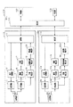
図1は、本実施形態に係る物体検知システムの構成図である。物体検知システムは、物体検知装置である超音波センサ10,10aと、その超音波センサ10,10aと通信可能に接続されたECU100とを含んで構成されている。超音波センサ10,10aは、共通の構造となっている。すなわち、超音波センサ10,10aは、共振周波数(共振周期)が共通している。この共振周波数は、共振特性と称することができる。なお、共振周波数が共通するという文言は、共振周波数が全く等しくなっていることのみならず、共振周波数を等しくなる設計のもとで製造されたものであれば、共振周波数が等しいと定義する。すなわち、超音波センサ10,10aの製造過程で共振周波数に誤差が生じていたとしても、共振周波数が等しいということができる。
FIG. 1 is a configuration diagram of an object detection system according to the present embodiment. The object detection system is configured to include
これら超音波センサ10,10aは、間隔を開けて配置されており、且つ、一方の超音波センサ10から探査波が送信され、周囲の物体によりその探査波が反射された場合、反射波はいずれの超音波センサ10,10aにおいても受信可能とされている。すなわち、超音波センサ10,10aは、自己が送信した探査波の反射波である直接波と、他のセンサが送信した探査波の反射波である間接波のいずれも受信可能である。なお、以下の説明において、一方の超音波センサ10についての説明を行う。他方の超音波センサ10aの各構成には、一方の超音波センサ10の各構成を示す符号に「a」の符号を追加して図示している。
These
超音波センサ10は、ECU100との通信を行う通信部11、その通信部11から探査波の送信制御の開始信号を受け取り、探査波の送信制御を行う送信制御部12、及び、その送信制御部12により駆動される送信回路13を備えている。送信回路13は、送信制御部12からの駆動信号により駆動させられ、所定周波数の駆動電力が送受信部14へと供給される。
The
送受信部14は、圧電素子を備える有底筒状の筐体の内側に圧電素子が取り付けられたものである。この送受信部14の具体的構造について、図2を参照して説明する。
The transmission/
送受信部14は、筐体141、圧電素子142と、スペーサ143、ベース144および接続ピン145を有して構成されている。
The transmitter/
筐体141は、導電性材料で構成され、有底円筒状とされることで筐体141の内部に内部空間146が形成されている。筐体141の底部141aの内面に圧電素子142が貼着されており、この底部141aの外側表面が送受信面となっている。本実施形態では、導電性材料としてアルミニウムを用いており、送受信面を円形状としている。
The
圧電素子142は、圧電セラミックス、例えばチタン酸ジルコン酸鉛系セラミックスで構成され、その表裏両面に電極を備えている。圧電素子142の一方の電極は、リード147aによって一対の接続ピン145の一方に電気的に接続されている。圧電素子142の他方の電極は、筐体141の底部141aに例えば導電性接着剤により貼着され、導電性材料で構成された筐体141を介してリード147bに接続されたのち、一対の接続ピン145の他方に電気的に接続されている。
The
スペーサ143は、筐体141の開口部とベース144との間に配置されている。スペーサ143は、筐体141の底部141aの振動に伴って筐体141に生じる不要振動が、ベース144に伝達されるのを抑制するための弾性体であり、例えばシリコーンゴムから構成されている。
The
ベース144は、筐体141の開口部側の外周面にスペーサ143を介して嵌め込まれることで、筐体141に固定されている。ベース144は絶縁材料、例えばABS樹脂等の合成樹脂で構成されている。ベース144には、接続ピン145を被覆するための保護部148が回路基板162側に突出するように設けられ、接続ピン145が保護部148を貫通するように配置されている。
The
そして、筐体141、スペーサ143、ベース144が、それぞれ接着されることで、一体構造とされた送受信部14が構成されている。このように構成された送受信部14は、円筒形状の弾性部材150に側面、及び底面の一部が覆われて、合成樹脂からなる中空の本体部160内に組み付けられる。
Then, the
本体部160は、中空状の略長方体で構成されている。本体部160の一面には、上端が開口した円筒形の側壁部161が設けられており、その側壁部161の内部に、送受信部14及び弾性部材150が収容される。送受信部14は、外周面に弾性部材150が当接させられると共に、下側に振動を抑制する弾性体となる発泡弾性体164が配置されて本体部160に組み付けられている。
The
本体部160には、回路基板162の接続位置に対して接続ピン145を位置決めするためのガイド部163が設けられている。このガイド部163は、本体部160の内部空間を送受信部14の配置空間と回路基板162の配置空間とに区画する板状部によって構成されている。
The
このように送受信部14を本体部160に組み付けた状態において、接続ピン145の先端部が回路基板162に挿入されている。この回路基板162には、図1における送受信部14を除く各部の機能に相当する電子部品等が、実装されている。
In this manner, the tip end portion of the
また、ガイド部163により区画された本体部160のうち回路基板162が配置される中空部には、防湿性部材165が充填されている。回路基板162には外部に出力するための外部出力端子167が備えられ、本体部160の一面に形成されたコネクタ166から外部出力端子167の一端側が露出させられた構成とされている。超音波センサ10とECU100との接続は、この外部出力端子167により行われる。
In addition, a moisture-
図1の説明に戻り、送信回路13から所定周波数の駆動電力が圧電素子へと供給され、圧電素子がその駆動電力により発振することで超音波を探査波として送信する。この探査波の周波数である送信周波数について、図3を参照して説明する。この送信周波数は、送信波の特性であるため、送信特性と称することができる。送信周波数としては、共振周波数f0よりも小さい第1周波数f1と、共振周波数f0よりも大きい第2周波数f2との一方が、送信制御部12により選択される。具体的には、共振周波数f0が66.7kHzとなっており、第1周波数f1は共振周波数f0よりも2kHz(第2所定値)小さい64.7kHzであり、第2周波数f2は共振周波数f0よりも2kHz(第1所定値)大きい68.7kHzである。すなわち、第1周波数f1は共振周波数f0よりも、共振周波数f0の3%だけ小さく、第2周波数f2は共振周波数f0よりも、共振周波数f0の3%だけ大きい。なお、第1周波数f1は第1特性ということができ、第2周波数f2は第2特性ということができる。
Returning to the explanation of FIG. 1, drive power of a predetermined frequency is supplied from the
探査波の送信後に周囲の物体により探査波が反射された場合、反射された超音波である反射波が送受信部14へ入射する。また、上述した通り、他方の超音波センサ10aの送受信部14aから探査波が送信されて物体に反射された場合においても、送受信部14へ反射波が入射する。
When the exploration wave is reflected by surrounding objects after the transmission of the exploration wave, the reflected wave that is the reflected ultrasonic wave enters the transmitting/receiving
送受信部14が備える圧電素子は、受信波によって振動し、受信波の周波数と等しい周波数を有し、且つ、受信波の振幅に比例する電圧を有する電気信号を発生させる。圧電素子が発生させた電気信号は、受信回路15へ入力される。受信回路15は、公知のバンドパスフィルタ回路を備え、探査波の周波数から乖離した周波数の受信波を除去する。
The piezoelectric element included in the transmission/
受信回路15から出力される電気信号は、閾値判定部16へ入力される。閾値判定部16は、受信波の振幅に対応する電圧が、予め定められた閾値よりも大きくなったか否かを判定する。すなわち、振幅が十分に大きく、反射波である可能性がある受信波を受信したか否かを判定する。閾値判定部16は、電気信号の電圧が閾値よりも大きくなった時刻である受信時刻を、距離算出部17へ送信する。
The electric signal output from the
距離算出部17は、送信制御部12から取得した探査波の送信時刻と、閾値から取得した受信波の受信時刻とに基づいて、物体との距離を算出する。具体的には、受信時刻から送信時刻を減算した値に音速を乗算し、その値の半分を物体との距離をする。
The
超音波センサ10は、さらに、受信波の位相を算出する位相算出部18を備える。この位相算出部18は、受信波の位相を直交検波により算出する。位相算出部18は、送信制御部12から探査波の送信周波数を取得し、受信回路15から受信波の周波数に等しい周波数を有する電気信号を取得する。この位相算出部18で行われる具体的処理について、図4を参照して説明する。
The
正弦波発生部181は、送信制御部12から共振周波数f0を取得し、その共振周波数f0の4倍の周波数の正弦波を発生させる。この正弦波は、第1乗算器182へ入力される。第1乗算器182は、受信信号に対して正弦波を乗算する。一方、正弦波発生部181により発生させられた正弦波は、余弦波変換部183に入力される。余弦波変換部183では、正弦波の周期を−π/2遅らせた余弦波を発生させる。この余弦波は、第2乗算器184へ入力される。第2乗算器184は、受信信号に対して余弦波を乗算する。
The sine
第1乗算器182の出力値、第2乗算器184の出力値は、それぞれローパスフィルタ185,186を経て、受信波の同相成分I、直交位相成分Qとして、演算部187へ入力される。演算部187は、同相成分I及び直交位相成分Qに基づいて受信波の位相を算出する。
The output value of the
位相算出部18の演算部187により算出された受信波の位相は、位相回転量算出部19へ入力される。上述した通り、受信波の位相を直交検波により算出するうえで、共振周波数f0を用いている。したがって、位相回転量算出部19は、受信波の位相を位相回転量とし、その位相回転量を周波数算出部20へ入力する。
The phase of the received wave calculated by the
周波数算出部20は、取得した位相回転量に基づいて、受信波の周波数である受信周波数を求める。具体的には、図示しないメモリに位相回転量と受信波の周波数の関係とを示すテーブル又は関数が記憶されており、そのテーブル又は関数に基づいて、位相回転量から受信周波数を特定する。この位相回転量と受信周波数との関係について、図5を参照して説明する。この位相回転量と受信周波数との関係については、演算により求められるものであるが、その関係は周知であるため、具体的な説明は省略する。なお、受信周波数は、受信特性ということができる。
The
図示のとおり、位相回転量と受信周波数との相関関係は、直線的な負の相関関係である。すなわち、位相回転量が大きくなるほど周波数は小さくなり、位相回転量が小さくなるほど周波数は大きくなる。また、上述した通り、共振周波数f0を用いて直交検波の処理を行っているため、位相回転量がゼロである場合の受信周波数は共振周波数f0である。 As shown in the figure, the correlation between the phase rotation amount and the reception frequency is a linear negative correlation. That is, the frequency decreases as the phase rotation amount increases, and the frequency increases as the phase rotation amount decreases. Further, as described above, since the quadrature detection processing is performed using the resonance frequency f0, the reception frequency when the phase rotation amount is zero is the resonance frequency f0.
第1周波数f1は共振周波数f0よりも小さく、第2周波数f2は共振周波数f0よりも大きく、且つ、第1周波数f1と共振周波数f0との差の絶対値と、第2周波数f2と共振周波数f0との差の絶対値とは等しい。したがって、位相回転量が正の値であるdである場合が第1周波数f1に対応しているとすれば、位相回転量が負の値である−dである場合に第2周波数f2に対応している。 The first frequency f1 is lower than the resonance frequency f0, the second frequency f2 is higher than the resonance frequency f0, and the absolute value of the difference between the first frequency f1 and the resonance frequency f0 and the second frequency f2 and the resonance frequency f0. Is equal to the absolute value of the difference. Therefore, if the case where the amount of phase rotation is a positive value d corresponds to the first frequency f1, the case where the amount of phase rotation is a negative value −d corresponds to the second frequency f2. doing.
以上のようにして、距離算出部17が算出した距離、及び、周波数算出部20が算出した受信周波数は、通信部11からECU100へと送信される。
As described above, the distance calculated by the
ECU100は、通信部101、制御部102、及び判定部103を備えている。通信部101は、各超音波センサ10,10aの通信部11,11aと接続されており、ECU100と各超音波センサ10,10aとの情報の送受信は、この通信部101を介して行われる。制御部102は、通信部101を介して物体との距離を取得する。判定部103は、通信部101を介して受信周波数を取得する。
The
判定部103は、受信波がいずれの超音波センサ10,10aの探査波の反射波であるかを判定する。具体的には、第1周波数f1に対して、周波数の範囲を示す第1範囲が設定されており、第1範囲の上限は、共振周波数f0よりも小さく第1周波数f1よりも大きい値であり、第1範囲の下限は、第1周波数f1よりも小さい値である。同様に、第2周波数f2に対して、周波数の範囲を示す第2範囲が設定されており、第2範囲の下限は、共振周波数f0よりも大きく第2周波数f2よりも小さい値であり、第2範囲の上限は、第2周波数f2よりも大きい値である。すなわち、第1範囲の上限は、第2範囲の下限よりも小さく設定されている。
The
そして、受信周波数が第1範囲内である場合、その受信波が、第1周波数f1で送信された探査波の反射波であると判定する。同様に、受信周波数が第2範囲内である場合、その受信波が、第2周波数f2で送信された探査波の反射波であると判定する。また、受信周波数が第1範囲内でなく第2範囲内でもない場合、受信波を混信波と判定する。すなわち、受信周波数が第1範囲の上限よりも大きく且つ第2範囲の下限よりも小さい場合においても、混信波であると判定する。なお、受信周波数が第1範囲の上限よりも大きく且つ第2範囲の下限よりも小さい場合には、受信周波数は共振周波数f0により近い値を取る。この場合には、判定部103による1度の判定のみで混信波であると確定せず、複数回混信波であるとの判定結果を得ることで、混信波であると確定してもよい。すなわち、受信周波数が第1範囲の上限よりも大きく且つ第2範囲の下限よりも小さい場合には、判定を制限するものとしてもよい。
Then, when the reception frequency is within the first range, it is determined that the reception wave is a reflected wave of the exploration wave transmitted at the first frequency f1. Similarly, when the reception frequency is within the second range, it is determined that the reception wave is a reflected wave of the exploration wave transmitted at the second frequency f2. If the received frequency is neither within the first range nor within the second range, the received wave is determined to be an interference wave. That is, even when the reception frequency is higher than the upper limit of the first range and lower than the lower limit of the second range, it is determined that the interference wave is present. When the reception frequency is higher than the upper limit of the first range and lower than the lower limit of the second range, the reception frequency takes a value closer to the resonance frequency f0. In this case, the interference wave may not be determined by the
この判定結果は、制御部102へ入力される。制御部102では、受信波がいずれかの超音波センサ10,10aの探査波の反射波であるとの判定結果を受信すれば、その受信波に対応する距離を用いた各種処理、すなわち、物体との衝突を回避する制御等を行う。この処理は周知の処理であるため、具体的な説明を省略する。また、受信波が混信波であると判定すれば、その受信波に基づく距離は、破棄する。
The determination result is input to the
以上のように構成される物体検知システムにおいて実行される一連の処理について、図6のフローチャートを参照して説明する。 A series of processes executed in the object detection system configured as described above will be described with reference to the flowchart of FIG.
まず、ステップS101にて、送信周波数を決定する。すなわち、第1周波数f1の探査波を送信するか第2周波数f2の探査波を送信するかを決定する。ステップS101にて送信周波数が決定されれば、続くステップS102にて、決定された送信周波数の探査波が送信される。 First, in step S101, the transmission frequency is determined. That is, it is determined whether to transmit the probe wave of the first frequency f1 or the probe wave of the second frequency f2. When the transmission frequency is determined in step S101, the exploration wave having the determined transmission frequency is transmitted in subsequent step S102.
探査波が送信されれば、続くステップS103にて受信波を取得したか否かを判定する。すなわち、受信波の振幅を示す電圧が閾値よりも大きくなったか否かを判定する。ステップS103にて否定判定すれば、すなわち、受信波の振幅を示す電圧が閾値以下であれば、ステップS103の判定を繰り返す。一方、ステップS103にて肯定判定すれば、ステップS104に進み、受信波の位相回転量を算出する。位相回転量が算出されれば、ステップS105に進み、位相回転量から受信周波数を算出する。 If the exploration wave is transmitted, it is determined in the subsequent step S103 whether or not the reception wave is acquired. That is, it is determined whether the voltage indicating the amplitude of the received wave has become larger than the threshold value. If a negative determination is made in step S103, that is, if the voltage indicating the amplitude of the received wave is less than or equal to the threshold value, the determination in step S103 is repeated. On the other hand, if an affirmative decision is made in step S103, the operation proceeds to step S104, in which the phase rotation amount of the received wave is calculated. When the phase rotation amount is calculated, the process proceeds to step S105, and the reception frequency is calculated from the phase rotation amount.
続くステップS106にて、受信周波数が送信周波数を含む所定範囲内であるか否かを判定する。すなわち、超音波センサ10において、受信波が自己の探査波の反射波であるか否かを判定する場合には、送信周波数が第1周波数f1であれば、受信周波数が第1周波数f1を含む第1範囲内であるか否かを判定し、送信周波数が第2周波数f2であれば、受信周波数が第2周波数f2を含む第2範囲内であるか否かを判定する。超音波センサ10において、受信波が他の超音波センサ10aの探査波の反射波であるか否かの判定についても、同様に行われる。
In subsequent step S106, it is determined whether or not the reception frequency is within a predetermined range including the transmission frequency. That is, in the
ステップS106にて肯定判定すれば、すなわち受信周波数が送信周波数を含む所定範囲内であれば、ステップS107へ進み、受信波が反射波であると判定する。ステップS107の判定がなされれば、受信波に基づく距離を用いて各種制御を行う。 If an affirmative determination is made in step S106, that is, if the reception frequency is within a predetermined range including the transmission frequency, the process proceeds to step S107, and it is determined that the reception wave is a reflected wave. If the determination in step S107 is made, various controls are performed using the distance based on the received wave.
一方、ステップS106にて否定判定すれば、すなわち受信周波数が送信周波数を含む所定範囲外であれば、ステップS108へ進み、受信波が混信波であると判定する。この場合には、その受信波に基づく距離に関する情報等を破棄し、一連の処理を終了する。 On the other hand, if a negative determination is made in step S106, that is, if the reception frequency is outside the predetermined range including the transmission frequency, the process proceeds to step S108 and it is determined that the reception wave is an interference wave. In this case, the information regarding the distance based on the received wave is discarded, and the series of processes is ended.
上記構成により、本実施形態に係る物体検知システムは、以下の効果を有する。 With the above configuration, the object detection system according to this embodiment has the following effects.
・複数の超音波センサ10,10aを備える物体検知システムにおいて、各超音波センサ10,10aの共振特性を共通化させているため、システム全体のコストの低減が可能である。このような物体検知システムにおいて、超音波センサ10,10aから探査波を送信する場合、一般的には共振周波数f0と一致する送信周波数の探査波のみを送信する。ところが、共振特性を共通化した場合、受信周波数を取得したとしても、受信波がいずれの超音波センサ10,10aから送信された反射波に基づくものであるかの判定が困難である。この点、本実施形態では、互いに送信周波数が異なる複数の探査波のうち、いずれかの探査波を送信するものとしているため、受信周波数を取得することで、その受信波がいずれの超音波センサ10,10aから送信された探査波の反射波であるかを判定することができる。したがって、超音波センサ10,10aの構造の共通化によるコストの低減を実現しつつ、反射波がいずれの超音波センサ10,10aから送信された探査波に基づくものであるかを適切に判定することができる。
-In an object detection system including a plurality of
・各超音波センサ10,10aにおいて、共振周波数f0と共通する送信周波数の探査波を送信する場合、いずれの超音波センサ10,10aから送信された探査波の反射波であるかを判定するためには、いずれかの超音波センサ10,10aから探査波が送信されてから所定の受信待機期間を経たあとに、他の超音波センサ10,10aから探査波を送信する。この場合には、送受信周期が長くなり、物体の検知精度が低下する。この点、本実施形態では、送信周波数が互いに異なる探査波を送信しているため、複数の送受信部14,14aから同時に探査波を送信したとしても、受信波の周波数を取得することで、その受信波がいずれの探査波の反射波であるかを判定することができる。したがって、送受信周期を短くすることができ、物体の検知精度を向上させることができる。
-When each
・第1周波数f1及び第2周波数f2が共振周波数f0に近づくほど、受信波を検出するうえでの感度は向上する。ところが、探査波を反射した物体が移動しているものである場合等には、ドップラ効果により、反射波の周波数は探査波の周波数と異なるものとなる。これにより、第1周波数f1及び第2周波数f2が共振周波数f0に近づくほど、受信波の周波数を検出した際に、いずれの周波数の探査波が反射されたものであるかの判定が困難となる。この点、本実施形態では、第1周波数f1を共振周波数f0よりも小さい値とし、第2周波数f2を共振周波数f0よりも大きい値としているため、第1周波数f1及び第2周波数f2と共振周波数f0との差を小さくすることと、第1周波数f1と第2周波数f2との差を大きくすることとを両立することができる。これにより、受信波を検出する上での感度を向上させつつ、その受信波がいずれの周波数の探査波が反射されたものであるかの判定を精度よく行うことができる。 -As the first frequency f1 and the second frequency f2 approach the resonance frequency f0, the sensitivity in detecting the received wave is improved. However, when the object reflecting the exploration wave is moving, etc., the frequency of the reflected wave becomes different from the frequency of the exploration wave due to the Doppler effect. As a result, the closer the first frequency f1 and the second frequency f2 are to the resonance frequency f0, the more difficult it becomes to determine which frequency of the exploration wave is reflected when the frequency of the received wave is detected. .. In this regard, in the present embodiment, the first frequency f1 is set to a value smaller than the resonance frequency f0, and the second frequency f2 is set to a value larger than the resonance frequency f0. Therefore, the first frequency f1 and the second frequency f2 and the resonance frequency f2 are set. It is possible to reduce both the difference from f0 and increase the difference between the first frequency f1 and the second frequency f2. With this, it is possible to improve the sensitivity in detecting the received wave and accurately determine which frequency the exploration wave of the received wave is reflected from.
・第1周波数f1及び第2周波数f2が共振周波数f0に近づくほど、受信波を検出するうえでの感度は向上する。ところが、探査波を反射した物体が移動しているものである場合等には、ドップラ効果により、反射波の周波数は探査波の周波数と異なるものとなる。これにより、第1周波数f1及び第2周波数f2が共振周波数f0に近づくほど、受信波の周波数を検出した際に、いずれの周波数の探査波が反射されたものであるかの判定が困難となる。本実施形態では、第1周波数f1と共振周波数f0との差、及び、第2周波数f2と共振周波数f0との差を、いずれも、3%としている。これにより、受信波の検出するうえでの感度を担保しつつ、いずれの周波数の探査波の反射波であるかの判定を適切に行うことが可能となる。 -As the first frequency f1 and the second frequency f2 approach the resonance frequency f0, the sensitivity in detecting the received wave is improved. However, when the object reflecting the exploration wave is moving, etc., the frequency of the reflected wave becomes different from the frequency of the exploration wave due to the Doppler effect. As a result, the closer the first frequency f1 and the second frequency f2 are to the resonance frequency f0, the more difficult it becomes to determine which frequency of the exploration wave is reflected when the frequency of the received wave is detected. .. In the present embodiment, the difference between the first frequency f1 and the resonance frequency f0 and the difference between the second frequency f2 and the resonance frequency f0 are both 3%. As a result, it is possible to appropriately determine the frequency of the exploration wave that is the reflected wave while ensuring the sensitivity in detecting the received wave.
・第1周波数f1及び第2周波数f2について、それぞれ、共振周波数f0との差を約3%としているため、第1周波数f1及び第2周波数f2を区別するうえで、周波数を精度よく検出する必要が生ずる。したがって、受信波のゼロクロス点間の時間の計測により周波数を求める場合、及び、高速フーリエ変換(FFT)により周波数を求める場合のいずれにおいても、サンプリング周期をより短くする必要がある。具体的には、周波数の10倍以上の周波数でサンプリングを行う必要がある。すなわち、サンプリング周期を短くして周波数の検出精度を向上させるうえで、装置の大型化、高コスト化が生じる。この点、受信波の位相回転量から周波数を求める場合、サンプリング周波数は、想定される受信波の周波数の2〜4倍程度でよい。したがって、本実施形態では受信波の位相回転量から周波数を求めているため、装置の大型化、高コスト化を抑制しつつ、周波数の検出精度を向上させることができる。
Since the difference between the first frequency f1 and the second frequency f2 and the resonance frequency f0 is about 3%, it is necessary to accurately detect the frequency in order to distinguish the first frequency f1 and the second frequency f2. Occurs. Therefore, it is necessary to shorten the sampling cycle both in the case of obtaining the frequency by measuring the time between the zero-cross points of the received wave and in the case of obtaining the frequency by the fast Fourier transform (FFT). Specifically, it is necessary to perform sampling at a
・受信波の周波数は、ドップラ効果により、探査波の周波数からのずれが生ずる場合がある。すなわち、探査波の送信周波数が第1周波数f1であっても、反射波の周波数が第1周波数f1よりも大きくなる場合もあるし、探査波の送信周波数が第2周波数f2であっても、反射波の周波数が第2周波数f2よりも小さくなる場合もある。これは、受信波の周波数が第1周波数f1と第2周波数f2との間の所定範囲である場合に、受信波の周波数がいずれの周波数の探査波に基づく反射波であるかの判定が困難であることを意味する。本実施形態では、受信波の周波数が第1周波数f1よりも大きく且つ第2周波数f2よりも小さい所定範囲内である場合に、周波数に基づく判定を制限しているため、受信波の誤判定に起因する物体の位置の誤検知を抑制することができる。 -The frequency of the received wave may deviate from the frequency of the exploratory wave due to the Doppler effect. That is, even if the transmission frequency of the search wave is the first frequency f1, the frequency of the reflected wave may be higher than the first frequency f1, and even if the transmission frequency of the search wave is the second frequency f2, The frequency of the reflected wave may be smaller than the second frequency f2. This is because when the frequency of the received wave is in the predetermined range between the first frequency f1 and the second frequency f2, it is difficult to determine which frequency the received wave is the reflected wave based on the search wave. Means that. In the present embodiment, when the frequency of the received wave is within a predetermined range that is higher than the first frequency f1 and lower than the second frequency f2, the determination based on the frequency is limited, so that the received wave is erroneously determined. It is possible to suppress erroneous detection of the position of the object caused by the error.
<第2実施形態>
本実施形態では、物体検知システムに含まれる超音波センサの配置について具体化している。図7を参照して、物体検知システムに含まれる超音波センサの配置について説明する。
<Second Embodiment>
In the present embodiment, the arrangement of ultrasonic sensors included in the object detection system is embodied. The arrangement of the ultrasonic sensors included in the object detection system will be described with reference to FIG. 7.
図7に示すように、車両の前方には、左側から順に、物体検知装置である第1〜第4前方センサ31〜34が互いに間隔を開けて(隣り合って)設けられている。車両の後方には、左側から順に、物体検知装置である第1〜第4後方センサ41〜44が互いに間隔を開けて(隣り合って)設けられている。車両の左側方には、前側から順に、物体検知装置である第1、2左側方センサ51,52が間隔を開けて(隣り合って)設けられており、車両の右側方には、前側から順に、物体検知装置である第1、2右側方センサ61,62が間隔を開けて(隣り合って)設けられている。また、第1前方センサ31と第1左側方センサ51とは隣り合って設けられている。第4前方センサ34と第1右側方センサ61とは隣り合って設けられている。第1後方センサ41と第2左側方センサ52とは隣り合って設けられている。第4後方センサ44と第2右側方センサ62とは隣り合って設けられている。
As shown in FIG. 7, first to fourth
第1〜第4前方センサ31〜34、第1左側方センサ51、及び第1右側方センサ61は、車両のフロントバンパに取り付けられており、第1〜第4後方センサ41〜44、第2左側方センサ52、及び第2右側方センサ62は、車両のリアバンパに取り付けられている。これら第1〜第4前方センサ31〜34、第1〜第4後方センサ41〜44、第1、2左側方センサ51,52、第1、2右側方センサ61,62の具体的な構成は、第1実施形態における超音波センサ10,10aと同じ構成である。すなわち、各センサ31〜34,41〜44,51,52,61,62は、共通の構成である。
The 1st-4th front sensor 31-34, the 1st
図7では、第1周波数f1で探査波を送信するセンサを三角で図示しており、第2周波数f2で探査波を送信するセンサを丸で図示している。すなわち、第1〜第4前方センサ31〜34及び第1〜第4後方センサ41〜44は第1周波数f1で探査波を送信するものとして設定されており、第1、2左側方センサ51,52、及び第1、2右側方センサ61,62は第2周波数f2で探査波を送信するものとして設定されている。
In FIG. 7, the sensor that transmits the exploration wave at the first frequency f1 is illustrated by a triangle, and the sensor that transmits the exploration wave at the second frequency f2 is illustrated by a circle. That is, the first to fourth
以上の構成の物体検知システムにおいて、間隔を開けて隣り合うセンサどうしでは、自己で送信した探査波の反射波に加えて、他のセンサが送信した探査波の反射波も受信可能である。 In the object detection system having the above configuration, the adjacent sensors with a space therebetween can receive the reflected wave of the exploratory wave transmitted by another sensor, in addition to the reflected wave of the exploratory wave transmitted by itself.
以下の説明において、車両の左前方のセンサ群、すなわち、第1前方センサ31、第2前方センサ32、及び第1左側方センサ51について説明する。車両の右前方のセンサ群、左後方のセンサ群、及び、右後方のセンサ群については、車両の左前方のセンサ群と同等の機能を有するもので、具体的な説明は省略する。
In the following description, the left front sensor group of the vehicle, that is, the first
車両の左前方のセンサ群において、第1前方センサ31は、自己が送信した探査波の反射波に加えて、第2前方センサ32の探査波に基づく反射波を受信可能であり、且つ、第1左側方センサ51の探査波に基づく反射波を受信可能である。また、第1左側方センサ51は、自己が送信した探査波の反射波に加えて、第1前方センサ31の探査波の反射波を受信可能である。
In the left front sensor group of the vehicle, the first
上述した通り、第1前方センサ31及び第2前方センサ32は、第1周波数f1で探査波を送信するものとして設定されており、第1左側方センサ51は第2周波数f2で探査波を送信するものとして設定されている。すなわち、車両において隣り合って設けられた第1前方センサ31と第1左側方センサ51とは、互いに周波数(送信特性)が異なる探査波を送信する。
As described above, the first
このように探査波の送信周波数が設定されているため、第2前方センサ32、及び第1左側方センサ51が探査波を送信した場合には、第1前方センサ31に入射した反射波がいずれのセンサから送信された探査波に基づくものであるのか判定することができる。
Since the transmission frequency of the exploration wave is set in this way, when the second
また、第1前方センサ31及び第1左側方センサ51が探査波を送信した場合には、第1前方センサ31に入射した反射波がいずれのセンサから送信された探査波に基づくものであるのか判定することができ、且つ、第1左側方センサ51に入射した反射波がいずれのセンサから送信された探査波に基づくものであるのか判定することができる。
When the first
上記構成により、本実施形態に係る物体検知システムは、第1実施形態に準ずる効果を奏する。 With the above configuration, the object detection system according to the present embodiment has an effect similar to that of the first embodiment.
<第3実施形態>
本実施形態では、物体検知システム全体の構成は第2実施形態と共通しており、各センサにおける送信周波数の一部を第2実施形態と異ならせている。図8を参照して、本実施形態に係る物体検知システムについて説明する。
<Third Embodiment>
In the present embodiment, the overall configuration of the object detection system is common to that of the second embodiment, and a part of the transmission frequency of each sensor is different from that of the second embodiment. The object detection system according to the present embodiment will be described with reference to FIG. 8.
図8では、第2実施形態と同様に、第1周波数f1で探査波を送信するセンサを三角で図示しており、第2周波数f2で探査波を送信するセンサを丸で図示している。すなわち、第1〜第4前方センサ31〜34、第2左側方センサ52、及び第2右側方センサ62は第1周波数f1で探査波を送信するものとして設定されており、第1〜第4後方センサ41〜44、第1左側方センサ51、及び第1右側方センサ61は第2周波数f2で探査波を送信するものとして設定されている。
In FIG. 8, similarly to the second embodiment, the sensor that transmits the exploration wave at the first frequency f1 is illustrated by a triangle, and the sensor that transmits the exploration wave at the second frequency f2 is illustrated by a circle. That is, the 1st-4th front sensor 31-34, the 2nd
以上のように構成される物体検知システムにおいて、第1左側方センサ51は隣り合う第2左側方センサ52が送信した探査波の反射波を受信可能であり、第2左側方センサ52は隣り合う第1左側方センサ51が送信した探査波の反射波を受信可能である。第1右側方センサ61は隣り合う第2右側方センサ62が送信した探査波の反射波を受信可能であり、第2右側方センサ62は隣り合う第1右側方センサ61が送信した探査波の反射波を受信可能である。この点、第1左側方センサ51の送信周波数と第2左側方センサ52の送信周波数とを異ならせているため、第1左側方センサ51、及び第2左側方センサ52のそれぞれにおいて、受信波がいずれのセンサの探査波の反射波であるかを判定することができる。同様に、第1右側方センサ61の送信周波数と第2右側方センサ62の送信周波数とを異ならせているため、第1右側方センサ61、及び第2右側方センサ62のそれぞれにおいて、受信波がいずれのセンサの探査波の反射波であるかを判定することができる。
In the object detection system configured as described above, the first
なお、車両の左前方のセンサ群、右前方のセンサ群、左後方のセンサ群、及び、右後方のセンサ群のそれぞれにおいては、第2実施形態と同等の機能であるため、具体的な説明を省略する。 Note that the left front sensor group, the right front sensor group, the left rear sensor group, and the right rear sensor group of the vehicle have the same functions as those in the second embodiment, and therefore a detailed description thereof will be given. Is omitted.
上記構成により、本実施形態に係る物体検知システムは、第1実施形態に準ずる効果を奏する。 With the above configuration, the object detection system according to the present embodiment has an effect similar to that of the first embodiment.
また、左側方センサが3つ以上設けられており、それらにおいて隣り合う探査波の周波数(送信特性)が互いに異なっていてもよい。すなわち、車両の左側方に少なくとも2つのセンサ(物体検知装置)が隣り合って設けられており、前記少なくとも2つのセンサにおいて隣り合うセンサの送信特性が互いに異なっていてもよい。右側方センサについても同様である。 Further, three or more left side sensors may be provided, and the frequencies (transmission characteristics) of the adjacent search waves in them may be different from each other. That is, at least two sensors (object detection devices) may be provided adjacent to each other on the left side of the vehicle, and the transmission characteristics of the adjacent sensors of the at least two sensors may be different from each other. The same applies to the right side sensor.
<第4実施形態>
本実施形態では、物体検知システム全体の構成は第2実施形態と共通しており、各センサにおける送信周波数の一部を第2実施形態と異ならせている。図9を参照して、本実施形態に係る物体検知システムについて説明する。
<Fourth Embodiment>
In the present embodiment, the overall configuration of the object detection system is common to that of the second embodiment, and a part of the transmission frequency of each sensor is different from that of the second embodiment. The object detection system according to the present embodiment will be described with reference to FIG. 9.
図9では、第2実施形態と同様に、第1周波数f1で探査波を送信するセンサを三角で図示しており、第2周波数f2で探査波を送信するセンサを丸で図示している。すなわち、第1、2前方センサ31,32、第3、4後方センサ43,44、第2左側方センサ52、及び第1右側方センサ61は第1周波数f1で探査波を送信するものとして設定されており、第3、4前方センサ33,34、第1、2後方センサ41,42、第1左側方センサ51、及び第2右側方センサ62は第2周波数f2で探査波を送信するものとして設定されている。
In FIG. 9, similarly to the second embodiment, the sensor that transmits the exploration wave at the first frequency f1 is illustrated by a triangle, and the sensor that transmits the exploration wave at the second frequency f2 is illustrated by a circle. That is, the first and second
以下の説明において、車両の前方のセンサ群、すなわち、第1〜4前方センサ31〜34について説明する。車両の後方のセンサ群、すなわち第1〜4後方センサ41〜44については、車両の前方のセンサ群と同等の機能を有するもので、具体的な説明は省略する。
In the following description, a sensor group in front of the vehicle, that is, the first to fourth
以上のように構成される物体検知システムにおいて、第2前方センサ32は、自己が送信した探査波の反射波に加えて、隣り合う第1前方センサ31の探査波に基づく反射波を受信可能であり、且つ、隣り合う第3前方センサ33の探査波に基づく反射波を受信可能である。また、第3前方センサ33は、自己が送信した探査波の反射波に加えて、隣り合う第2前方センサ32の探査波の反射波を受信可能であり、且つ、隣り合う第4前方センサ34の探査波の反射波を受信可能である。
In the object detection system configured as described above, the second
上述した通り、第1、2前方センサ31,32は、第1周波数f1で探査波を送信するものとして設定されており、第3、4前方センサ33,34は第2周波数f2で探査波を送信するものとして設定されている。
As described above, the first and second
このように探査波の送信周波数が設定されているため、第1前方センサ31、及び第3前方センサ33が探査波を送信した場合には、第2前方センサ32に入射した反射波がいずれのセンサから送信された探査波に基づくものであるのか判定することができる。同様に、第2前方センサ32、及び第4前方センサ34が探査波を送信した場合には、第3前方センサ33に入射した反射波がいずれのセンサから送信された探査波に基づくものであるのか判定することができる。
Since the transmission frequency of the exploration wave is set in this way, when the first
また、第2前方センサ32及び第3前方センサ33が探査波を送信した場合には、第2前方センサ32、第3前方センサ33のそれぞれにおいて、入射した反射波がいずれのセンサから送信された探査波に基づくものであるのか判定することができる。
Further, when the second
なお、車両の左前方のセンサ群、右前方のセンサ群、左後方のセンサ群、及び、右後方のセンサ群のそれぞれにおいては、第2実施形態と同等の機能であるため、具体的な説明を省略する。 Note that the left front sensor group, the right front sensor group, the left rear sensor group, and the right rear sensor group of the vehicle have the same functions as those in the second embodiment, and therefore a detailed description thereof will be given. Is omitted.
上記構成により、本実施形態に係る物体検知システムは、第1実施形態に準ずる効果を奏する。 With the above configuration, the object detection system according to the present embodiment has an effect similar to that of the first embodiment.
また、第1〜4前方センサ31〜34の全てにおいて、隣り合う探査波の周波数(送信特性)が互いに異なっていもよい。すなわち、車両の前端部に少なくとも2つのセンサ(物体検知装置)が隣り合って設けられており、前記少なくとも2つのセンサにおいて隣り合うセンサの送信特性が互いに異なっていてもよい。車両の後端部に設けられるセンサについても同様である。
Further, in all of the first to fourth
<第5実施形態>
本実施形態では、物体検知システム全体の構成は第2実施形態と共通しており、処理の一部を第2実施形態と異ならせている。本実施形態における処理について、図10を参照して説明する。
<Fifth Embodiment>
In this embodiment, the overall configuration of the object detection system is common to that of the second embodiment, and part of the processing is different from that of the second embodiment. The processing in this embodiment will be described with reference to FIG.
本実施形態では、送信周波数を第2実施形態と同様に設定した第1設定(図10(a)に図示)と、送信周波数を第2実施形態と異ならせた第2設定(図10(b)に図示)とを切り替えて用いる。 In this embodiment, the first setting (shown in FIG. 10A) in which the transmission frequency is set in the same manner as in the second embodiment and the second setting (FIG. 10(b) in which the transmission frequency is different from that in the second embodiment are set. ) And) are switched and used.
第2設定では、図10(b)に図示するように、第1設定において第1周波数f1で探査波を送信するセンサについては、第2周波数f2で探査波を送信するものとし、第1設定において第2周波数f2で探査波を送信するセンサについては、第1周波数f1で探査波を送信するものとしている。すなわち、第1〜第4前方センサ31〜34及び第1〜第4後方センサ41〜44は第2周波数f2で探査波を送信するものとして設定されており、第1、2左側方センサ51,52、及び第1、2右側方センサ61,62は第1周波数f1で探査波を送信するものとして設定されている。
In the second setting, as shown in FIG. 10B, regarding the sensor that transmits the exploratory wave at the first frequency f1 in the first setting, the exploratory wave is transmitted at the second frequency f2, and the first setting In regard to the sensor that transmits the exploration wave at the second frequency f2, it is assumed that the sensor transmits the exploration wave at the first frequency f1. That is, the first to fourth
第1設定と第2設定との切り替えは、所定期間ごとに行われる。この場合には、各センサでそれぞれ1回ずつ送受信制御が行われることを所定期間として設定してもよいし、各センサでそれぞれ複数回の送受信制御が行われることを所定期間として設定してもよい。 The switching between the first setting and the second setting is performed every predetermined period. In this case, the transmission/reception control performed by each sensor once may be set as the predetermined period, or the transmission/reception control performed by each sensor multiple times may be set as the predetermined period. Good.
上記構成により、本実施形態に係る物体検知システムは、以下の効果を奏する。 With the above configuration, the object detection system according to the present embodiment has the following effects.
・物体検知システムの近傍に、同じ送信周波数で探査波を送信する他の超音波センサが存在する場合、他の超音波センサから送信された探査波を受信し、自己の探査波の反射波であると誤認識する可能性がある。この点、本実施形態では、送信周波数を所定期間ごとに切り替えるものとしているため、探査波の送信周波数を、他の超音波センサの探査波の送信周波数と異なるものとすることができ、混信を抑制することができる。 ・If another ultrasonic sensor that transmits a probe wave at the same transmission frequency exists near the object detection system, the probe wave transmitted from the other ultrasonic sensor is received and reflected by its own probe wave. There is a possibility of erroneously recognizing that there is. In this regard, in the present embodiment, since the transmission frequency is switched for each predetermined period, the transmission frequency of the exploration wave can be different from the transmission frequency of the exploration wave of the other ultrasonic sensor, and interference can be prevented. Can be suppressed.
なお、自車が第1周波数f1で送信し、他車も第1周波数f1で送信するような場合には、自車の送信周波数を第2周波数f2に切り替えたら、混信が生じていることを認識できる。この場合には、変更後の送信周波数から変更前の送信周波数へと戻さず、変更後の送信周波数での物体検知を継続するものとしてもよい。こうすることで、他車から送信された探査波及び反射波を混信波として除外しつつ、物体の検知を行うことができる。 In addition, when the own vehicle transmits at the first frequency f1 and the other vehicles also transmit at the first frequency f1, when the transmission frequency of the own vehicle is switched to the second frequency f2, interference may occur. Can be recognized. In this case, the object transmission may be continued at the changed transmission frequency without returning from the changed transmission frequency to the transmission frequency before the change. By doing so, it is possible to detect the object while excluding the search wave and the reflected wave transmitted from another vehicle as the interference wave.
<第6実施形態>
本実施形態では、物体検知システム全体の構成は第2実施形態と共通しており、各センサにおける送信周波数の一部を第2実施形態と異ならせている。図11を参照して、本実施形態に係る物体検知システムについて説明する。
<Sixth Embodiment>
In the present embodiment, the overall configuration of the object detection system is common to that of the second embodiment, and a part of the transmission frequency of each sensor is different from that of the second embodiment. The object detection system according to this embodiment will be described with reference to FIG. 11.
本実施形態では、第1〜5実施形態と同様に、第1周波数f1、第2周波数f2を用いるとともに、さらに第3周波数f3も用いるものとしている。この第3周波数f3は、第1周波数f1よりも小さくてもよいし、第2周波数f2よりも大きくてもよい。また、第1周波数f1よりも大きく且つ第2周波数f2よりも小さくてもよく、この場合には、第3周波数f3を共振周波数f0と等しくしてもよい。 In the present embodiment, similarly to the first to fifth embodiments, the first frequency f1 and the second frequency f2 are used, and the third frequency f3 is also used. The third frequency f3 may be lower than the first frequency f1 or higher than the second frequency f2. Further, it may be higher than the first frequency f1 and lower than the second frequency f2, and in this case, the third frequency f3 may be equal to the resonance frequency f0.
図11では、第1周波数f1で探査波を送信するセンサを三角で図示しており、第2周波数f2で探査波を送信するセンサを丸で図示しており、第3周波数f3で探査波を送信するセンサを四角で図示している。すなわち、第1〜第4前方センサ31〜34及び第1〜第4後方センサ41〜44は第1周波数f1で探査波を送信するものとして設定されており、第1、2左側方センサ51,52は第3周波数f3で探査波を送信するものとして設定されており、第1、2右側方センサ61,62は第2周波数f2で探査波を送信するものとして設定されている。
In FIG. 11, the sensor that transmits the exploration wave at the first frequency f1 is illustrated by a triangle, the sensor that transmits the exploration wave at the second frequency f2 is illustrated by a circle, and the sensor that transmits the exploration wave at the third frequency f3 is illustrated. The sensors that transmit are shown as squares. That is, the first to fourth
このように送信周波数を設定することで、本実施形態に係る物体検知システムは、第2実施形態に係る物体検知システムが奏する効果に加えて、以下の効果を奏する。 By setting the transmission frequency in this way, the object detection system according to the present embodiment has the following effects in addition to the effects of the object detection system according to the second embodiment.
・本実施形態と同等の構成の物体検知システムを備える車両が並走する場合、一方の車両の左側方と他方の車両の右側方とが近接することとなる。このとき、車両どうしの距離が近いほど、他の車両のセンサから送信される探査波を受信しやすくなる。本実施形態では、第1、2左側方センサ51,52の送信周波数と、第1、2右側方センサ61,62の送信周波数を異なるものとしているため、車両が横並びとなり、他の車両に設けられた物体検知システムの探査波を受信した場合に、判定部103は、受信波が、他の物体検知システムの探査波等に起因するものであると判定し、自己の距離計測には用いないものとすることができる。したがって、本実施形態と同等の構成の物体検知システムを備える車両が横並びになった場合における混信を、抑制することができる。
-When vehicles equipped with the object detection system of the same composition as this embodiment run in parallel, the left side of one vehicle and the right side of the other vehicle will approach. At this time, the closer the vehicles are to each other, the easier it is to receive the exploration wave transmitted from the sensor of another vehicle. In the present embodiment, the transmission frequencies of the first and second
また、第1〜第4前方センサ31〜34を省略したり、第1〜第4後方センサ41〜44を省略したり、第1〜第4前方センサ31〜34及び第1〜第4後方センサ41〜44を省略したりしてもよい。
Further, the first to fourth
<第7実施形態>
本実施形態では、物体検知システム全体の構成は第2実施形態と共通しており、各センサにおける送信周波数の一部を第2実施形態と異ならせている。図12を参照して、本実施形態に係る物体検知システムについて説明する。
<Seventh Embodiment>
In the present embodiment, the overall configuration of the object detection system is common to that of the second embodiment, and a part of the transmission frequency of each sensor is different from that of the second embodiment. The object detection system according to the present embodiment will be described with reference to FIG.
本実施形態では、第6実施形態と同様に、第1周波数f1、第2周波数f2及び第3周波数f3を用いるものとしている。 In this embodiment, as in the sixth embodiment, the first frequency f1, the second frequency f2, and the third frequency f3 are used.
図12では、第1周波数f1で探査波を送信するセンサを三角で図示しており、第2周波数f2で探査波を送信するセンサを丸で図示しており、第3周波数f3で探査波を送信するセンサを四角で図示している。すなわち、第1〜第4前方センサ31〜34は第2周波数f2で探査波を送信するものとして設定されており、第1〜第4後方センサ41〜44は第3周波数f3で探査波を送信するものとして設定されており、第1、2左側方センサ51,52及び第1、2右側方センサ61,62は第1周波数f1で探査波を送信するものとして設定されている。
In FIG. 12, the sensor that transmits the exploratory wave at the first frequency f1 is shown by a triangle, the sensor that transmits the exploratory wave at the second frequency f2 is shown by a circle, and the sensor that transmits the exploratory wave at the third frequency f3 is shown. The sensors that transmit are shown as squares. That is, the first to fourth
このように送信周波数を設定することで、本実施形態に係る物体検知システムは、第2実施形態に係る物体検知システムが奏する効果に加えて、以下の効果を奏する。 By setting the transmission frequency in this way, the object detection system according to the present embodiment has the following effects in addition to the effects of the object detection system according to the second embodiment.
・本実施形態と同等の構成の物体検知システムを備える車両が縦並びになった場合、例えば、渋滞している道路を走行している場合、一方の車両の前端部と他方の車両の後端部とが近接することとなる。このとき、車両どうしの距離が近いほど、他の車両の物体検知システムから送信される探査波を受信しやすくなる。本実施形態では、前方センサ31〜34の送信周波数と、後方センサ41〜44の送信周波数を異なるものとしているため、車両が縦並びとなり、他の車両に設けられた物体検知システムの探査波を受信した場合に、判定部103は、受信波が、他の物体検知システムの探査波等に起因するものであると判定し、自己の距離計測には用いないものとすることができる。したがって、本実施形態と同等の構成の物体検知システムを備える車両が縦並びになった場合における混信を、抑制することができる。
When the vehicles equipped with the object detection system having the same configuration as the present embodiment are vertically aligned, for example, when traveling on a congested road, the front end of one vehicle and the rear end of the other vehicle And will be close. At this time, the closer the vehicles are to each other, the easier it is to receive the exploration wave transmitted from the object detection system of another vehicle. In the present embodiment, the transmission frequencies of the
<第8実施形態>
本実施形態では、物体検知システム全体の構成は第2実施形態と共通しており、各センサにおける送信周波数の一部を第2実施形態と異ならせている。図13を参照して、本実施形態に係る物体検知システムについて説明する。
<Eighth Embodiment>
In the present embodiment, the overall configuration of the object detection system is common to that of the second embodiment, and a part of the transmission frequency of each sensor is different from that of the second embodiment. The object detection system according to the present embodiment will be described with reference to FIG.
本実施形態では、第6、7実施形態と同様に、第1周波数f1、第2周波数f2及び第3周波数f3を用いるものとしている。 In this embodiment, as in the sixth and seventh embodiments, the first frequency f1, the second frequency f2, and the third frequency f3 are used.
図13では、第1周波数f1で探査波を送信するセンサを三角で図示しており、第2周波数f2で探査波を送信するセンサを丸で図示しており、第3周波数f3で探査波を送信するセンサを四角で図示している。すなわち、第1前方センサ31、第4前方センサ34、第1後方センサ41、第4後方センサ44は第1周波数f1で探査波を送信するものとして設定されており、第3前方センサ33、第2後方センサ42、第1左側方センサ51、第2右側方センサ62は第2周波数f2で探査波を送信するものとして設定されており、第2前方センサ32、第3後方センサ43、第2左側方センサ52、第1右側方センサ61は第3周波数f3で探査波を送信するものとしている。
In FIG. 13, the sensor that transmits the exploration wave at the first frequency f1 is illustrated by a triangle, the sensor that transmits the exploration wave at the second frequency f2 is illustrated by a circle, and the sensor that transmits the exploration wave at the third frequency f3 is illustrated. The sensors that transmit are shown as squares. That is, the first
このように送信周波数を設定することで、いずれのセンサにおいても、自己の送信周波数及び両隣の送信周波数がいずれも異なるものとなる。したがって、いずれかのセンサ及びその両隣のセンサから探査波を送信した場合においても、受信波がいずれのセンサの探査波の反射波であるかを判定することができる。これは、仮にすべてのセンサから探査波をほぼ同時に送信したとしても、各センサにおいて受信波がいずれのセンサの探査波の反射波であるかを判定できることを意味している。 By setting the transmission frequency in this way, the self-transmission frequency and the transmission frequencies on both sides become different in any sensor. Therefore, even when the search wave is transmitted from any of the sensors and the sensors on both sides of the sensor, it is possible to determine which of the sensors the received wave is a reflected wave of the search wave. This means that even if the exploration waves are transmitted from all the sensors at substantially the same time, it is possible for each sensor to determine which sensor the received wave is a reflected wave of the exploration wave.
なお、図14に示すように、第1前方センサ31、第3前方センサ33、第1右側方センサ61、第2後方センサ42、第4後方センサ44、第2左側方センサ52は第1周波数f1(送信特性)で探査波を送信するものとして設定されており、第2前方センサ32、第4前方センサ34、第1後方センサ41、第3後方センサ43、第1左側方センサ51、第2右側方センサ62は第2周波数f2(送信特性)で探査波を送信するものとして設定されていてもよい。その構成において、第2前方センサ32、第3前方センサ33、第2後方センサ42、第3後方センサ43を省略したり、第1左側方センサ51、第2左側方センサ52、第1右側方センサ61、第2右側方センサ62を省略したりしてもよい。すなわち、車両の外周縁部に少なくとも8つのセンサ(物体検知装置)が隣り合って設けられており、前記少なくとも8つのセンサにおいて隣り合うセンサの送信特性が互いに異なっていてもよい。
As shown in FIG. 14, the first
<第9実施形態>
本実施形態では、物体検知システム全体の構成は第2実施形態と共通しており、処理の一部を第2実施形態と異ならせている。本実施形態における処理について、図15を参照して説明する。
<Ninth Embodiment>
In this embodiment, the overall configuration of the object detection system is common to that of the second embodiment, and part of the processing is different from that of the second embodiment. The processing in this embodiment will be described with reference to FIG.
本実施形態では、第1設定(図15(a)に図示)と、第2設定(図15(b)に図示)とを切り替えて用いる。 In the present embodiment, the first setting (shown in FIG. 15A) and the second setting (shown in FIG. 15B) are switched and used.
第1設定では、図15(a)に図示するように、第2前方センサ32、第3後方センサ43、第2左側方センサ52、及び第1右側方センサ61は第1周波数f1で探査波を送信するものとして設定されており、第3前方センサ33、第2後方センサ42、第1左側方センサ51、及び第2右側方センサ62は第2周波数f2で探査波を送信するものとして設定されている。破線で示した第1前方センサ31、第4前方センサ34、第1後方センサ41、第4後方センサ44は探査波を送信しない。
In the first setting, as illustrated in FIG. 15A, the second
第2設定では、図15(b)に図示するように、第1設定において探査波を送信するセンサについては探査波を送信しないものとし、第1設定において探査波を送信しないセンサについては探査波を送信するものとしている。すなわち、第4前方センサ34及び第1後方センサ41は第1周波数f1で探査波を送信するものとして設定されており、第1前方センサ31及び第4後方センサ44は第2周波数f2で探査波を送信するものとして設定されている。破線で示した第2前方センサ32、第3前方センサ33、第2後方センサ42、第3後方センサ43、第1左側方センサ51、第2左側方センサ52、第1右側方センサ61、及び第2右側方センサ62は探査波を送信しない。
In the second setting, as shown in FIG. 15B, the sensor that transmits the exploration wave in the first setting does not transmit the exploration wave, and the sensor that does not transmit the exploration wave in the first setting does not Shall be sent. That is, the fourth
第1設定と第2設定との切り替えは、所定期間ごとに行われる。この場合には、各センサでそれぞれ1回ずつ送受信制御が行われることを所定期間として設定してもよいし、各センサでそれぞれ複数回の送受信制御が行われることを所定期間として設定してもよい。 The switching between the first setting and the second setting is performed every predetermined period. In this case, the transmission/reception control performed by each sensor once may be set as the predetermined period, or the transmission/reception control performed by each sensor multiple times may be set as the predetermined period. Good.
上記構成により、本実施形態に係る物体検知システムは、以下の効果を奏する。 With the above configuration, the object detection system according to the present embodiment has the following effects.
・例えば、車両の左前方のセンサ群では、互いに送信特性が異なる第2前方センサ32及び第1左側方センサ51が間隔を開けて設けられている。このため、第1前方センサ31が取得した受信特性に基づいて、その受信波が第2前方センサ32及び第1左側方センサ51のうちいずれの送信特性の探査波の反射波であるかを判定することができる。なお、車両の右前方のセンサ群、左後方のセンサ群、及び右後方のセンサ群でも同様である。
-For example, in the sensor group on the left front side of the vehicle, the second
・送信周波数を所定期間ごとに切り替えるものとしているため、探査波の送信周波数を、他の超音波センサの探査波の送信周波数と異なるものとすることができ、混信を抑制することができる。 Since the transmission frequency is switched every predetermined period, the transmission frequency of the search wave can be different from the transmission frequency of the search wave of another ultrasonic sensor, and interference can be suppressed.
・第1実施形態に準ずる効果を奏する。 -The effect equivalent to 1st Embodiment is produced.
<第10実施形態>
本実施形態では、物体検知システム全体の構成は第2実施形態と共通しており、処理の一部を第2実施形態と異ならせている。本実施形態における処理について、図16を参照して説明する。
<Tenth Embodiment>
In this embodiment, the overall configuration of the object detection system is common to that of the second embodiment, and part of the processing is different from that of the second embodiment. The processing in this embodiment will be described with reference to FIG.
本実施形態では、第1設定(図16(a)に図示)と、第2設定(図16(b)に図示)とを切り替えて用いる。 In the present embodiment, the first setting (illustrated in FIG. 16A) and the second setting (illustrated in FIG. 16B) are switched and used.
第1設定では、図16(a)に図示するように、第9実施形態の図15(a)と同様の設定にしている。 In the first setting, as shown in FIG. 16A, the same setting as that in FIG. 15A of the ninth embodiment is made.
第2設定では、図16(b)に図示するように、第9実施形態の図15(b)と同様の設定に加えて、第1右側方センサ61は第2周波数f2で探査波を送信するものとして設定されており、第2右側方センサ62は第1周波数f1で探査波を送信するものとして設定されている。すなわち、第1左側方センサ51、第2左側方センサ52、第1右側方センサ61、及び第2右側方センサ62は、常に探査を送信している。
In the second setting, as shown in FIG. 16(b), in addition to the same setting as in FIG. 15(b) of the ninth embodiment, the first
上記構成により、本実施形態に係る物体検知システムは、第9実施形態に準ずる効果を奏する。さらに、第1左側方センサ51、第2左側方センサ52、第1右側方センサ61、及び第2右側方センサ62は、常に探査を送信しているため、側方の物体を常に検知することができる。
With the above configuration, the object detection system according to the present embodiment has an effect similar to that of the ninth embodiment. Further, the first
<第11実施形態>
本実施形態では、物体検知システム全体の構成は第2実施形態と共通しており、処理の一部を第2実施形態と異ならせている。本実施形態における処理について、図17を参照して説明する。
<Eleventh Embodiment>
In this embodiment, the overall configuration of the object detection system is common to that of the second embodiment, and part of the processing is different from that of the second embodiment. The processing in this embodiment will be described with reference to FIG.
本実施形態では、第1設定(図17(a)に図示)と、第2設定(図17(b)に図示)とを切り替えて用いる。 In the present embodiment, the first setting (illustrated in FIG. 17A) and the second setting (illustrated in FIG. 17B) are switched and used.
第1設定では、図17(a)に図示するように、第1前方センサ31、第4後方センサ44、第2左側方センサ52、及び第1右側方センサ61は第1周波数f1で探査波を送信するものとして設定されており、第3前方センサ33、第2後方センサ42は第2周波数f2で探査波を送信するものとして設定されている。破線で示した第2前方センサ32、第4前方センサ34、第1後方センサ41、第3後方センサ43、第1左側方センサ51、及び第2右側方センサ62は探査波を送信しない。
In the first setting, as illustrated in FIG. 17A, the first
第2設定では、図17(b)に図示するように、第1設定において探査波を送信するセンサについては探査波を送信しないものとし、第1設定において探査波を送信しないセンサについては探査波を送信するものとしている。すなわち、第2前方センサ32及び第2右側方センサ62は第1周波数f1で探査波を送信するものとして設定されており、第4前方センサ34及び第1左側方センサ51は第2周波数f2で探査波を送信するものとして設定されている。破線で示した第1前方センサ31、第3前方センサ33、第2後方センサ42、第4後方センサ44、第2左側方センサ52、及び第1右側方センサ61は探査波を送信しない。
In the second setting, as illustrated in FIG. 17B, it is assumed that the sensor that transmits the exploratory wave in the first setting does not transmit the exploratory wave and that the sensor that does not transmit the exploratory wave in the first setting does not transmit the exploratory wave. Is supposed to be sent. That is, the second
第1設定と第2設定との切り替えは、所定期間ごとに行われる。この場合には、各センサでそれぞれ1回ずつ送受信制御が行われることを所定期間として設定してもよいし、各センサでそれぞれ複数回の送受信制御が行われることを所定期間として設定してもよい。 The switching between the first setting and the second setting is performed every predetermined period. In this case, the transmission/reception control performed by each sensor once may be set as the predetermined period, or the transmission/reception control performed by each sensor multiple times may be set as the predetermined period. Good.
上記構成により、本実施形態に係る物体検知システムは、以下の効果を奏する。 With the above configuration, the object detection system according to the present embodiment has the following effects.
・例えば、車両の前側のセンサ群では、互いに送信特性が異なる第2前方センサ32及び第1左側方センサ51が間隔を開けて設けられている。このため、第1前方センサ31が取得した受信特性に基づいて、その受信波が第2前方センサ32及び第1左側方センサ51のうちいずれの送信特性の探査波の反射波であるかを判定することができる。第3前方センサ33が取得した受信特性に基づいて、その受信波が第2前方センサ32及び第4前方センサ34のうちいずれの送信特性の探査波の反射波であるかを判定することができる。なお、車両の後側のセンサ群でも同様である。
-For example, in the sensor group on the front side of the vehicle, the second
・送信周波数を所定期間ごとに切り替えるものとしているため、探査波の送信周波数を、他の超音波センサの探査波の送信周波数と異なるものとすることができ、混信を抑制することができる。 Since the transmission frequency is switched every predetermined period, the transmission frequency of the search wave can be different from the transmission frequency of the search wave of another ultrasonic sensor, and interference can be suppressed.
・第1実施形態に準ずる効果を奏する。 -The effect equivalent to 1st Embodiment is produced.
<第12実施形態>
本実施形態では、物体検知システム全体の構成は第2実施形態と共通しており、処理の一部を第2実施形態と異ならせている。本実施形態における処理について、図18を参照して説明する。
<Twelfth Embodiment>
In this embodiment, the overall configuration of the object detection system is common to that of the second embodiment, and part of the processing is different from that of the second embodiment. The processing in this embodiment will be described with reference to FIG.
本実施形態では、第1設定(図18(a)に図示)と、第2設定(図18(b)に図示)とを切り替えて用いる。 In the present embodiment, the first setting (illustrated in FIG. 18A) and the second setting (illustrated in FIG. 18B) are switched and used.
第1設定では、図18(a)に図示するように、第11実施形態の図17(a)と同様の設定に加えて、第1左側方センサ51及び第2右側方センサ62は第2周波数f2で探査波を送信するものとして設定されている。
In the first setting, as shown in FIG. 18A, in addition to the same settings as in FIG. 17A of the eleventh embodiment, the first
第2設定では、図18(b)に図示するように、第11実施形態の図17(b)と同様の設定に加えて、第2左側方センサ52及び第1右側方センサ61は第1周波数f1で探査波を送信するものとして設定されている。すなわち、第1左側方センサ51、第2左側方センサ52、第1右側方センサ61、及び第2右側方センサ62は、常に探査を送信している。
In the second setting, as shown in FIG. 18B, in addition to the setting similar to that of FIG. 17B of the eleventh embodiment, the second
上記構成により、本実施形態に係る物体検知システムは、第11実施形態に準ずる効果を奏する。さらに、第1左側方センサ51、第2左側方センサ52、第1右側方センサ61、及び第2右側方センサ62は、常に探査を送信しているため、側方の物体を常に検知することができる。
With the above configuration, the object detection system according to the present embodiment has an effect similar to that of the eleventh embodiment. Further, the first
<変形例>
・各実施形態では、受信波の周波数によっては位相が360°以上回転することもあるため位相回転量という文言を用いているが、位相差と称してもよい。
<Modification>
In each of the embodiments, the term “phase rotation amount” is used because the phase may rotate by 360° or more depending on the frequency of the received wave, but it may be called a phase difference.
・実施形態では、位相回転量を求めるうえで共振周波数f0を用いて直交検波を行うものとしたが、第1周波数f1又は第2周波数f2を用いて直交検波を行うものとしてもよい。若しくは、第1周波数f1を用いた直交検波、及び第2周波数f2を用いた直交検波を共に行うものとしてもよい。 In the embodiment, the quadrature detection is performed by using the resonance frequency f0 in obtaining the phase rotation amount, but the quadrature detection may be performed by using the first frequency f1 or the second frequency f2. Alternatively, the quadrature detection using the first frequency f1 and the quadrature detection using the second frequency f2 may be performed together.
・第1実施形態において、第1周波数f1及び第2周波数f2と共振周波数f0との差を、共振周波数f0の3%としたが、第1周波数f1及び第2周波数f2と共振周波数f0との差をこれよりも大きくしてもよいし小さくしてもよい。ただし、第1周波数f1及び第2周波数f2を共振周波数f0に近づけるほど、第1周波数f1と第2周波数f2との差が小さくなるため、ドップラ効果で反射波の周波数が変化した場合には、いずれの周波数で送信された探査波の反射波であるかの判定が困難となる。また、第1周波数f1及び第2周波数f2を共振周波数f0から遠ざけるほど、反射波の取得が困難になる。したがって、第1周波数f1及び第2周波数f2と共振周波数f0との差は、共振周波数f0の2〜5%であることが好ましい。 In the first embodiment, the difference between the first frequency f1 and the second frequency f2 and the resonance frequency f0 is 3% of the resonance frequency f0, but the first frequency f1 and the second frequency f2 are different from the resonance frequency f0. The difference may be larger or smaller than this. However, the closer the first frequency f1 and the second frequency f2 are to the resonance frequency f0, the smaller the difference between the first frequency f1 and the second frequency f2 becomes. Therefore, when the frequency of the reflected wave changes due to the Doppler effect, It becomes difficult to determine which frequency is the reflected wave of the probe wave transmitted. Further, the further the first frequency f1 and the second frequency f2 are from the resonance frequency f0, the more difficult it is to acquire the reflected wave. Therefore, the difference between the resonance frequency f0 and the first frequency f1 and the second frequency f2 is preferably 2 to 5% of the resonance frequency f0.
・第1周波数f1と共振周波数f0との差、及び、第2周波数f2と共振周波数f0との差は、等しくなくてもよい。 The difference between the first frequency f1 and the resonance frequency f0 and the difference between the second frequency f2 and the resonance frequency f0 may not be equal.
・第1周波数f1及び第2周波数f2が、共に、共振周波数f0よりも大きくてもよい。また、第1周波数f1及び第2周波数f2が、共に、共振周波数f0よりも小さくてもよい。 Both the first frequency f1 and the second frequency f2 may be higher than the resonance frequency f0. Further, both the first frequency f1 and the second frequency f2 may be smaller than the resonance frequency f0.
・第1周波数f1及び第2周波数f2の一方が共振周波数f0であってもよい。 -One of the first frequency f1 and the second frequency f2 may be the resonance frequency f0.
・実施形態では、送信周波数として第1周波数f1及び第2周波数f2を用いるもの、及び、第1〜3周波数f1〜f3を用いるものを例示したが、4種類以上の送信周波数を用いるものとしてもよい。 In the embodiment, the first frequency f1 and the second frequency f2 are used as the transmission frequencies, and the first to third frequencies f1 to f3 are used, but four or more types of transmission frequencies may be used. Good.
・実施形態では、判定部103をECU100に設けるものとしたが、判定部103を超音波センサ10,10aに設けてもよい。また、超音波センサ10,10aの機能の一部をECU100に設けるものとしてもよい。
In the embodiment, the
・送受信部14の具体的な構造及び形状については、図2で示したものに限られず、他の構造及び形状としてもよい。
The specific structure and shape of the transmitting/receiving
・実施形態では、共振特性として共振周波数f0を用いており、第1特性として第1周波数f1を用いており、第2特性として第2周波数f2を用いているが、周波数の代わりに周波数の逆数である周期を用いるものとしてもよい。同様に、送信特性として送信周波数を用いる代わりに周期を用いるものとしてもよいし、受信特性として受信周波数を用いる代わりに、周期を用いるものとしてもよい。 In the embodiment, the resonance frequency f0 is used as the resonance characteristic, the first frequency f1 is used as the first characteristic, and the second frequency f2 is used as the second characteristic, but the reciprocal of the frequency is used instead of the frequency. May be used. Similarly, a cycle may be used instead of the transmission frequency as the transmission characteristic, or a cycle may be used instead of the reception frequency as the reception characteristic.
また、探査波の送信特性として、周波数及び周期に限らず、位相や振幅を異ならせることもできる。例えば、変調部が、複数のパルスからなるパルス列を信号生成部から取得し、複数の符号の組合せで構成される符号系列に従って、パルス信号のパルス列ごとに位相を変更する。位相算出部は、復調部から受信波の復調に用いる信号を取得し、受信波の復調を行って受信波の位相を算出する。そして、判定部は、取得した位相と探査波の位相とを比較し、取得した位相と探査波の位相との差が予め定められた所定値以内である場合に、受信波が探査波の反射波であると判定する。また、探査波の位相を切り替えることに代えて、オフ期間を設けるものとしてもよい。この場合には、オフ期間を設けることで、振幅の包絡線のピークが複数生ずることとなる。振幅の包絡線のピークが複数生ずれば、反射波の振幅の包絡線についても複数のピークが生ずることとなるため、受信波が探査波の反射波であるか否かを判定することができる。要するに、複数のセンサ(物体検知装置)は、互いに、送受信部14、14aが送信可能な探査波の周波数に共通範囲を有しており、共通範囲内の周波数の探査波に基づいて、周波数、周期、位相、及び振幅等の送信特性が異なる複数の探査波のうち、いずれかの探査波を送受信部14、14aから送信させる送信制御部12,12aを備えていればよい。
Further, the transmission characteristics of the exploration wave are not limited to the frequency and the period, and the phase and the amplitude can be different. For example, the modulator acquires a pulse train composed of a plurality of pulses from the signal generator, and changes the phase for each pulse train of the pulse signal in accordance with a code sequence formed of a combination of a plurality of codes. The phase calculation unit acquires a signal used for demodulating the received wave from the demodulation unit, demodulates the received wave, and calculates the phase of the received wave. Then, the determining unit compares the acquired phase with the phase of the exploration wave, and when the difference between the acquired phase and the phase of the exploration wave is within a predetermined value set in advance, the received wave reflects the exploration wave. Judge as a wave. Further, instead of switching the phase of the exploration wave, an off period may be provided. In this case, providing the off period causes a plurality of peaks of the amplitude envelope. If multiple peaks of the amplitude envelope occur, multiple peaks will also occur for the amplitude envelope of the reflected wave, so it is possible to determine whether the received wave is the reflected wave of the exploration wave. .. In short, the plurality of sensors (object detection devices) have a common range in the frequency of the exploratory wave that can be transmitted by the transmission/
・第5実施形態において、送信周波数を切り替える処理を行ううえで、切替前と切替後の周波数は第5実施形態で示したものに限られない。 In the fifth embodiment, the frequency before and after switching is not limited to that shown in the fifth embodiment when performing the process of switching the transmission frequency.
・実施形態では、物体検知システムを車両に搭載するものとしたが、搭載対象は車両に限られない。 In the embodiment, the object detection system is mounted on the vehicle, but the mounting target is not limited to the vehicle.
10…超音波センサ、10a…超音波センサ、12…送信制御部、14…送受信部、14a…送受信部、18…位相算出部、19…位相回転量算出部、20…周波数算出部、31〜34…前方センサ、41〜44…後方センサ、51,52…左側方センサ、61,62…右側方センサ、103…判定部、141…筐体、142…圧電素子。 10... Ultrasonic sensor, 10a... Ultrasonic sensor, 12... Transmission control part, 14... Transmission/reception part, 14a... Transmission/reception part, 18... Phase calculation part, 19... Phase rotation amount calculation part, 20... Frequency calculation part, 31... 34... Front sensor, 41-44... Rear sensor, 51, 52... Left side sensor, 61, 62... Right side sensor, 103... Judgment part, 141... Housing, 142... Piezoelectric element.
Claims (20)
複数の前記物体検知装置は、互いに、前記送受信部の共振周波数及び共振周期の少なくとも一方を示す共振特性が共通しており、
前記送受信部は、周波数及び周期の少なくとも一方を示す送信特性が前記共振特性を含む所定範囲内である前記探査波を送信可能であり、且つ、周波数及び周期の少なくとも一方を示す受信特性が前記共振特性を含む所定範囲内である前記受信波を受信可能であり、
前記所定範囲内において互いに前記送信特性が異なる複数の探査波のうち、いずれかの探査波を前記送受信部から送信させる送信制御部(12,12a)と、
前記受信波の前記受信特性を取得する特性取得部(18〜20,18a〜20a)と、を備え、
前記車両の前端部には、左側から順に前記物体検知装置である第1〜第4前方センサ(31〜34)が互いに間隔を開けて設けられており、
前記車両の後端部には、左側から順に前記物体検知装置である第1〜第4後方センサ(41〜44)が互いに間隔を開けて設けられており、
前記車両の左側方には、前側から順に前記物体検知装置である第1,第2左側方センサ(51,52)が間隔を開けて設けられており、
前記車両の右側方には、前側から順に前記物体検知装置である第1,第2右側方センサ(61,62)が間隔を開けて設けられており、
前記物体検知装置は、前記送信特性を第1設定と第2設定とに所定期間ごとに切り替え、
前記第1設定では、前記第1〜第4前方センサ(31〜34)及び前記第1〜第4後方センサ(41〜44)は、前記送信特性である第1送信特性で前記探査を送信し、前記第1,第2左側方センサ(51,52)及び前記第1,第2右側方センサ(61,62)は、前記第1送信特性と異なる前記送信特性である第2送信特性で前記探査を送信し、
前記第2設定では、前記第1〜第4前方センサ(31〜34)及び前記第1〜第4後方センサ(41〜44)は、前記第2送信特性で前記探査を送信し、前記第1,第2左側方センサ(51,52)及び前記第1,第2右側方センサ(61,62)は、前記第1送信特性で前記探査を送信し、
取得した前記受信特性に基づいて、その受信波がいずれの送信特性の探査波の反射波であるかを判定する判定部(103)を備える、物体検知システム。 An object detection device (10, 10a, 31-34, which transmits an exploration wave from the transmission/reception unit (14, 14a) and acquires a reception wave including a reflected wave from a surrounding object by the transmission/reception unit to detect the object. 41-44, 51, 52, 61, 62), and is an object detection system mounted on a vehicle ,
The plurality of object detection devices have mutually common resonance characteristics indicating at least one of the resonance frequency and the resonance cycle of the transmission/reception unit,
The transmission/reception unit can transmit the exploration wave whose transmission characteristic indicating at least one of frequency and cycle is within a predetermined range including the resonance characteristic, and the reception characteristic indicating at least one of frequency and cycle is the resonance. It is possible to receive the received wave within a predetermined range including characteristics,
A transmission control unit (12, 12a) for transmitting any of the search waves from the plurality of search waves having different transmission characteristics within the predetermined range;
A characteristic acquisition unit (18 to 20, 18a to 20a) for acquiring the reception characteristic of the received wave ,
First to fourth front sensors (31 to 34), which are the object detection devices, are provided at a front end portion of the vehicle in order from the left side with a space therebetween.
First to fourth rear sensors (41 to 44), which are the object detection devices, are provided at a rear end portion of the vehicle in order from the left side with a space therebetween.
On the left side of the vehicle, first and second left side sensors (51, 52), which are the object detection devices, are provided at intervals from the front side,
On the right side of the vehicle, first and second right side sensors (61, 62), which are the object detection devices, are provided at intervals from the front side,
The object detection device switches the transmission characteristic between a first setting and a second setting every predetermined period,
In the first setting, the first to fourth front sensors (31 to 34) and the first to fourth rear sensors (41 to 44) transmit the search with the first transmission characteristic which is the transmission characteristic. The first and second left side sensors (51, 52) and the first and second right side sensors (61, 62) have the second transmission characteristic that is the transmission characteristic different from the first transmission characteristic. Send exploration,
In the second setting, the first to fourth front sensors (31 to 34) and the first to fourth rear sensors (41 to 44) transmit the probe with the second transmission characteristic, and the first to fourth sensors. , A second left side sensor (51, 52) and the first and second right side sensors (61, 62) transmit the probe with the first transmission characteristic,
An object detection system, comprising: a determination unit (103 ) that determines, based on the acquired reception characteristic, the reception wave that is a reflected wave of an exploration wave of which transmission characteristic.
複数の前記物体検知装置は、互いに、前記送受信部が送信可能な探査波の周波数に共通範囲を有しており、
前記共通範囲内の周波数の前記探査波に基づいて、送信特性が異なる複数の探査波のうち、いずれかの探査波を前記送受信部から送信させる送信制御部(12,12a)と、
前記受信波の受信特性を取得する特性取得部(18〜20,18a〜20a)と、を備え、
前記車両の前端部には、左側から順に前記物体検知装置である第1〜第4前方センサ(31〜34)が互いに間隔を開けて設けられており、
前記車両の後端部には、左側から順に前記物体検知装置である第1〜第4後方センサ(41〜44)が互いに間隔を開けて設けられており、
前記車両の左側方には、前側から順に前記物体検知装置である第1,第2左側方センサ(51,52)が間隔を開けて設けられており、
前記車両の右側方には、前側から順に前記物体検知装置である第1,第2右側方センサ(61,62)が間隔を開けて設けられており、
前記物体検知装置は、前記送信特性を第1設定と第2設定とに所定期間ごとに切り替え、
前記第1設定では、前記第1〜第4前方センサ(31〜34)及び前記第1〜第4後方センサ(41〜44)は、前記送信特性である第1送信特性で前記探査を送信し、前記第1,第2左側方センサ(51,52)及び前記第1,第2右側方センサ(61,62)は、前記第1送信特性と異なる前記送信特性である第2送信特性で前記探査を送信し、
前記第2設定では、前記第1〜第4前方センサ(31〜34)及び前記第1〜第4後方センサ(41〜44)は、前記第2送信特性で前記探査を送信し、前記第1,第2左側方センサ(51,52)及び前記第1,第2右側方センサ(61,62)は、前記第1送信特性で前記探査を送信し、
取得した前記受信特性に基づいて、その受信波がいずれの送信特性の探査波の反射波であるかを判定する判定部(103)を備える、物体検知システム。 An object detection device (10, 10a, 31-34, which transmits an exploration wave from the transmission/reception unit (14, 14a) and acquires a reception wave including a reflected wave from a surrounding object by the transmission/reception unit to detect the object. 41-44, 51, 52, 61, 62), and is an object detection system mounted on a vehicle,
The plurality of object detection devices have a common range in the frequency of the exploration wave that the transmitting/receiving unit can transmit,
A transmission control unit (12, 12a) for transmitting one of the search waves from the plurality of search waves having different transmission characteristics based on the search wave having a frequency within the common range;
A characteristic acquisition unit (18 to 20, 18a to 20a) for acquiring the reception characteristic of the received wave ,
First to fourth front sensors (31 to 34), which are the object detection devices, are provided at a front end portion of the vehicle in order from the left side with a space therebetween.
First to fourth rear sensors (41 to 44), which are the object detection devices, are provided at a rear end portion of the vehicle in order from the left side with a space therebetween.
On the left side of the vehicle, first and second left side sensors (51, 52), which are the object detection devices, are provided at intervals from the front side,
On the right side of the vehicle, first and second right side sensors (61, 62), which are the object detection devices, are provided at intervals from the front side,
The object detection device switches the transmission characteristic between a first setting and a second setting every predetermined period,
In the first setting, the first to fourth front sensors (31 to 34) and the first to fourth rear sensors (41 to 44) transmit the search with the first transmission characteristic which is the transmission characteristic. The first and second left side sensors (51, 52) and the first and second right side sensors (61, 62) have the second transmission characteristic that is the transmission characteristic different from the first transmission characteristic. Send exploration,
In the second setting, the first to fourth front sensors (31 to 34) and the first to fourth rear sensors (41 to 44) transmit the probe with the second transmission characteristic, and the first to fourth sensors. , A second left side sensor (51, 52) and the first and second right side sensors (61, 62) transmit the probe with the first transmission characteristic,
An object detection system, comprising: a determination unit (103 ) that determines, based on the acquired reception characteristic, the reception wave that is a reflected wave of an exploration wave of which transmission characteristic.
複数の前記物体検知装置は、互いに、前記送受信部の共振周波数及び共振周期の少なくとも一方を示す共振特性が共通しており、The plurality of object detection devices have mutually common resonance characteristics indicating at least one of the resonance frequency and the resonance cycle of the transmission/reception unit,
前記送受信部は、周波数及び周期の少なくとも一方を示す送信特性が前記共振特性を含む所定範囲内である前記探査波を送信可能であり、且つ、周波数及び周期の少なくとも一方を示す受信特性が前記共振特性を含む所定範囲内である前記受信波を受信可能であり、The transmission/reception unit can transmit the exploration wave whose transmission characteristic indicating at least one of frequency and cycle is within a predetermined range including the resonance characteristic, and the reception characteristic indicating at least one of frequency and cycle is the resonance. It is possible to receive the received wave within a predetermined range including characteristics,
前記所定範囲内において互いに前記送信特性が異なる複数の探査波のうち、いずれかの探査波を前記送受信部から送信させる送信制御部(12,12a)と、A transmission control unit (12, 12a) for transmitting any of the search waves from the plurality of search waves having different transmission characteristics within the predetermined range;
前記受信波の前記受信特性を取得する特性取得部(18〜20,18a〜20a)と、を備え、A characteristic acquisition unit (18 to 20, 18a to 20a) for acquiring the reception characteristic of the received wave,
前記車両の前端部には、左側から順に前記物体検知装置である第1〜第4前方センサ(31〜34)が互いに間隔を開けて設けられており、First to fourth front sensors (31 to 34), which are the object detection devices, are provided at a front end portion of the vehicle in order from the left side with a space therebetween.
前記車両の後端部には、左側から順に前記物体検知装置である第1〜第4後方センサ(41〜44)が互いに間隔を開けて設けられており、First to fourth rear sensors (41 to 44), which are the object detection devices, are provided at a rear end portion of the vehicle in order from the left side with a space therebetween.
前記車両の左側方には、前側から順に前記物体検知装置である第1,第2左側方センサ(51,52)が間隔を開けて設けられており、On the left side of the vehicle, first and second left side sensors (51, 52), which are the object detection devices, are provided at intervals from the front side,
前記車両の右側方には、前側から順に前記物体検知装置である第1,第2右側方センサ(61,62)が間隔を開けて設けられており、On the right side of the vehicle, first and second right side sensors (61, 62), which are the object detection devices, are provided at intervals from the front side,
前記第1前方センサ(31)、前記第4前方センサ(34)、前記第1後方センサ(41)、及び前記第4後方センサ(44)は、前記送信特性である第1送信特性で前記探査を送信し、前記第3前方センサ(33)、前記第2後方センサ(42)、前記第1左側方センサ(51)、及び前記第2右側方センサ(62)は、前記第1送信特性と異なる前記送信特性である第2送信特性で前記探査を送信し、前記第2前方センサ(32)、前記第3後方センサ(43)、前記第2左側方センサ(52)、及び前記第1右側方センサ(61)は、前記第1送信特性及び前記第2送信特性と異なる前記送信特性である第3送信特性で前記探査を送信し、The first front sensor (31), the fourth front sensor (34), the first rear sensor (41), and the fourth rear sensor (44) have the first transmission characteristic, which is the transmission characteristic, for the search. And the third front sensor (33), the second rear sensor (42), the first left side sensor (51), and the second right side sensor (62) have the first transmission characteristic. The probe is transmitted with a second transmission characteristic that is the different transmission characteristic, and the second front sensor (32), the third rear sensor (43), the second left side sensor (52), and the first right side are transmitted. A direction sensor (61) transmits the probe with a third transmission characteristic which is the transmission characteristic different from the first transmission characteristic and the second transmission characteristic,
取得した前記受信特性に基づいて、その受信波がいずれの送信特性の探査波の反射波であるかを判定する判定部(103)を備える、物体検知システム。An object detection system, comprising: a determination unit (103) that determines, based on the acquired reception characteristic, the reception wave that is a reflected wave of a search wave having any transmission characteristic.
複数の前記物体検知装置は、互いに、前記送受信部が送信可能な探査波の周波数に共通範囲を有しており、The plurality of object detection devices have a common range in the frequency of the exploration wave that the transmitting/receiving unit can transmit,
前記共通範囲内の周波数の前記探査波に基づいて、送信特性が異なる複数の探査波のうち、いずれかの探査波を前記送受信部から送信させる送信制御部(12,12a)と、A transmission control unit (12, 12a) for transmitting one of the search waves from the plurality of search waves having different transmission characteristics based on the search wave having a frequency within the common range;
前記受信波の受信特性を取得する特性取得部(18〜20,18a〜20a)と、を備え、A characteristic acquisition unit (18 to 20, 18a to 20a) for acquiring the reception characteristic of the received wave,
前記車両の前端部には、左側から順に前記物体検知装置である第1〜第4前方センサ(31〜34)が互いに間隔を開けて設けられており、First to fourth front sensors (31 to 34), which are the object detection devices, are provided at a front end portion of the vehicle in order from the left side with a space therebetween.
前記車両の後端部には、左側から順に前記物体検知装置である第1〜第4後方センサ(41〜44)が互いに間隔を開けて設けられており、First to fourth rear sensors (41 to 44), which are the object detection devices, are provided at a rear end portion of the vehicle in order from the left side with a space therebetween.
前記車両の左側方には、前側から順に前記物体検知装置である第1,第2左側方センサ(51,52)が間隔を開けて設けられており、On the left side of the vehicle, first and second left side sensors (51, 52), which are the object detection devices, are provided at intervals from the front side,
前記車両の右側方には、前側から順に前記物体検知装置である第1,第2右側方センサ(61,62)が間隔を開けて設けられており、On the right side of the vehicle, first and second right side sensors (61, 62), which are the object detection devices, are provided at intervals from the front side,
前記第1前方センサ(31)、前記第4前方センサ(34)、前記第1後方センサ(41)、及び前記第4後方センサ(44)は、前記送信特性である第1送信特性で前記探査を送信し、前記第3前方センサ(33)、前記第2後方センサ(42)、前記第1左側方センサ(51)、及び前記第2右側方センサ(62)は、前記第1送信特性と異なる前記送信特性である第2送信特性で前記探査を送信し、前記第2前方センサ(32)、前記第3後方センサ(43)、前記第2左側方センサ(52)、及び前記第1右側方センサ(61)は、前記第1送信特性及び前記第2送信特性と異なる前記送信特性である第3送信特性で前記探査を送信し、The first front sensor (31), the fourth front sensor (34), the first rear sensor (41), and the fourth rear sensor (44) have the first transmission characteristic, which is the transmission characteristic, for the search. And the third front sensor (33), the second rear sensor (42), the first left side sensor (51), and the second right side sensor (62) have the first transmission characteristic. The probe is transmitted with a second transmission characteristic that is the different transmission characteristic, and the second front sensor (32), the third rear sensor (43), the second left side sensor (52), and the first right side are transmitted. A direction sensor (61) transmits the probe with a third transmission characteristic which is the transmission characteristic different from the first transmission characteristic and the second transmission characteristic,
取得した前記受信特性に基づいて、その受信波がいずれの送信特性の探査波の反射波であるかを判定する判定部(103)を備える、物体検知システム。An object detection system, comprising: a determination unit (103) that determines, based on the acquired reception characteristic, the reception wave that is a reflected wave of a search wave having any transmission characteristic.
複数の前記物体検知装置は、互いに、前記送受信部の共振周波数及び共振周期の少なくとも一方を示す共振特性が共通しており、The plurality of object detection devices have mutually common resonance characteristics indicating at least one of the resonance frequency and the resonance cycle of the transmission/reception unit,
前記送受信部は、周波数及び周期の少なくとも一方を示す送信特性が前記共振特性を含む所定範囲内である前記探査波を送信可能であり、且つ、周波数及び周期の少なくとも一方を示す受信特性が前記共振特性を含む所定範囲内である前記受信波を受信可能であり、The transmission/reception unit can transmit the exploration wave whose transmission characteristic indicating at least one of frequency and cycle is within a predetermined range including the resonance characteristic, and the reception characteristic indicating at least one of frequency and cycle is the resonance. It is possible to receive the received wave within a predetermined range including characteristics,
前記所定範囲内において互いに前記送信特性が異なる複数の探査波のうち、いずれかの探査波を前記送受信部から送信させる送信制御部(12,12a)と、A transmission control unit (12, 12a) for transmitting any of the search waves from the plurality of search waves having different transmission characteristics within the predetermined range;
前記受信波の前記受信特性を取得する特性取得部(18〜20,18a〜20a)と、を備え、A characteristic acquisition unit (18 to 20, 18a to 20a) for acquiring the reception characteristic of the received wave,
前記車両の前端部には、左側から順に前記物体検知装置である第1〜第4前方センサ(31〜34)が互いに間隔を開けて設けられており、First to fourth front sensors (31 to 34), which are the object detection devices, are provided at a front end portion of the vehicle in order from the left side with a space therebetween.
前記車両の後端部には、左側から順に前記物体検知装置である第1〜第4後方センサ(41〜44)が互いに間隔を開けて設けられており、First to fourth rear sensors (41 to 44), which are the object detection devices, are provided at a rear end portion of the vehicle in order from the left side with a space therebetween.
前記車両の左側方には、前側から順に前記物体検知装置である第1,第2左側方センサ(51,52)が間隔を開けて設けられており、On the left side of the vehicle, first and second left side sensors (51, 52), which are the object detection devices, are provided at intervals from the front side,
前記車両の右側方には、前側から順に前記物体検知装置である第1,第2右側方センサ(61,62)が間隔を開けて設けられており、On the right side of the vehicle, first and second right side sensors (61, 62), which are the object detection devices, are provided at intervals from the front side,
前記物体検知装置は、前記送信特性を第1設定と第2設定とに所定期間ごとに切り替え、The object detection device switches the transmission characteristic between a first setting and a second setting every predetermined period,
前記第1設定では、前記第2前方センサ(32)、前記第3後方センサ(43)、前記第2左側方センサ(52)、及び前記第1右側方センサ(61)は、前記送信特性である第1送信特性で前記探査を送信し、前記第3前方センサ(33)、前記第2後方センサ(42)、前記第1左側方センサ(51)、及び前記第2右側方センサ(62)は、前記第1送信特性と異なる前記送信特性である第2送信特性で前記探査を送信し、In the first setting, the second front sensor (32), the third rear sensor (43), the second left side sensor (52), and the first right side sensor (61) have the transmission characteristics. The probe is transmitted with a certain first transmission characteristic, and the third front sensor (33), the second rear sensor (42), the first left side sensor (51), and the second right side sensor (62). Transmits the probe with a second transmission characteristic that is the transmission characteristic different from the first transmission characteristic,
前記第2設定では、前記第4前方センサ(34)及び前記第1後方センサ(41)は、前記第1送信特性で前記探査を送信し、前記第1前方センサ(31)及び前記第4後方センサ(44)は、前記2送信特性で前記探査を送信し、In the second setting, the fourth front sensor (34) and the first rear sensor (41) transmit the probe with the first transmission characteristic, the first front sensor (31) and the fourth rear sensor. A sensor (44) transmits the probe with the two transmission characteristics,
取得した前記受信特性に基づいて、その受信波がいずれの送信特性の探査波の反射波であるかを判定する判定部(103)を備える、物体検知システム。An object detection system, comprising: a determination unit (103) that determines, based on the acquired reception characteristic, the reception wave that is a reflected wave of a search wave having any transmission characteristic.
複数の前記物体検知装置は、互いに、前記送受信部が送信可能な探査波の周波数に共通範囲を有しており、The plurality of object detection devices have a common range in the frequency of the exploration wave that the transmitting/receiving unit can transmit,
前記共通範囲内の周波数の前記探査波に基づいて、送信特性が異なる複数の探査波のうち、いずれかの探査波を前記送受信部から送信させる送信制御部(12,12a)と、A transmission control unit (12, 12a) for transmitting one of the search waves from the plurality of search waves having different transmission characteristics based on the search wave having a frequency within the common range;
前記受信波の受信特性を取得する特性取得部(18〜20,18a〜20a)と、を備え、A characteristic acquisition unit (18 to 20, 18a to 20a) for acquiring the reception characteristic of the received wave,
前記車両の前端部には、左側から順に前記物体検知装置である第1〜第4前方センサ(31〜34)が互いに間隔を開けて設けられており、First to fourth front sensors (31 to 34), which are the object detection devices, are provided at a front end portion of the vehicle in order from the left side with a space therebetween.
前記車両の後端部には、左側から順に前記物体検知装置である第1〜第4後方センサ(41〜44)が互いに間隔を開けて設けられており、First to fourth rear sensors (41 to 44), which are the object detection devices, are provided at a rear end portion of the vehicle in order from the left side with a space therebetween.
前記車両の左側方には、前側から順に前記物体検知装置である第1,第2左側方センサ(51,52)が間隔を開けて設けられており、On the left side of the vehicle, first and second left side sensors (51, 52), which are the object detection devices, are provided at intervals from the front side,
前記車両の右側方には、前側から順に前記物体検知装置である第1,第2右側方センサ(61,62)が間隔を開けて設けられており、On the right side of the vehicle, first and second right side sensors (61, 62), which are the object detection devices, are provided at intervals from the front side,
前記物体検知装置は、前記送信特性を第1設定と第2設定とに所定期間ごとに切り替え、The object detection device switches the transmission characteristic between a first setting and a second setting every predetermined period,
前記第1設定では、前記第2前方センサ(32)、前記第3後方センサ(43)、前記第2左側方センサ(52)、及び前記第1右側方センサ(61)は、前記送信特性である第1送信特性で前記探査を送信し、前記第3前方センサ(33)、前記第2後方センサ(42)、前記第1左側方センサ(51)、及び前記第2右側方センサ(62)は、前記第1送信特性と異なる前記送信特性である第2送信特性で前記探査を送信し、In the first setting, the second front sensor (32), the third rear sensor (43), the second left side sensor (52), and the first right side sensor (61) have the transmission characteristics. The probe is transmitted with a certain first transmission characteristic, and the third front sensor (33), the second rear sensor (42), the first left side sensor (51), and the second right side sensor (62). Transmits the probe with a second transmission characteristic that is the transmission characteristic different from the first transmission characteristic,
前記第2設定では、前記第4前方センサ(34)及び前記第1後方センサ(41)は、前記第1送信特性で前記探査を送信し、前記第1前方センサ(31)及び前記第4後方センサ(44)は、前記2送信特性で前記探査を送信し、In the second setting, the fourth front sensor (34) and the first rear sensor (41) transmit the probe with the first transmission characteristic, the first front sensor (31) and the fourth rear sensor. A sensor (44) transmits the probe with the two transmission characteristics,
取得した前記受信特性に基づいて、その受信波がいずれの送信特性の探査波の反射波であるかを判定する判定部(103)を備える、物体検知システム。An object detection system, comprising: a determination unit (103) that determines, based on the acquired reception characteristic, the reception wave that is a reflected wave of a search wave having any transmission characteristic.
複数の前記物体検知装置は、互いに、前記送受信部の共振周波数及び共振周期の少なくとも一方を示す共振特性が共通しており、The plurality of object detection devices have mutually common resonance characteristics indicating at least one of the resonance frequency and the resonance cycle of the transmission/reception unit,
前記送受信部は、周波数及び周期の少なくとも一方を示す送信特性が前記共振特性を含む所定範囲内である前記探査波を送信可能であり、且つ、周波数及び周期の少なくとも一方を示す受信特性が前記共振特性を含む所定範囲内である前記受信波を受信可能であり、The transmission/reception unit can transmit the exploration wave whose transmission characteristic indicating at least one of frequency and cycle is within a predetermined range including the resonance characteristic, and the reception characteristic indicating at least one of frequency and cycle is the resonance. It is possible to receive the received wave within a predetermined range including characteristics,
前記所定範囲内において互いに前記送信特性が異なる複数の探査波のうち、いずれかの探査波を前記送受信部から送信させる送信制御部(12,12a)と、A transmission control unit (12, 12a) for transmitting any of the search waves from the plurality of search waves having different transmission characteristics within the predetermined range;
前記受信波の前記受信特性を取得する特性取得部(18〜20,18a〜20a)と、を備え、A characteristic acquisition unit (18 to 20, 18a to 20a) for acquiring the reception characteristic of the received wave,
前記車両の前端部には、左側から順に前記物体検知装置である第1〜第4前方センサ(31〜34)が互いに間隔を開けて設けられており、First to fourth front sensors (31 to 34), which are the object detection devices, are provided at a front end portion of the vehicle in order from the left side with a space therebetween.
前記車両の後端部には、左側から順に前記物体検知装置である第1〜第4後方センサ(41〜44)が互いに間隔を開けて設けられており、First to fourth rear sensors (41 to 44), which are the object detection devices, are provided at a rear end portion of the vehicle in order from the left side with a space therebetween.
前記車両の左側方には、前側から順に前記物体検知装置である第1,第2左側方センサ(51,52)が間隔を開けて設けられており、On the left side of the vehicle, first and second left side sensors (51, 52), which are the object detection devices, are provided at intervals from the front side,
前記車両の右側方には、前側から順に前記物体検知装置である第1,第2右側方センサ(61,62)が間隔を開けて設けられており、On the right side of the vehicle, first and second right side sensors (61, 62), which are the object detection devices, are provided at intervals from the front side,
前記物体検知装置は、前記送信特性を第1設定と第2設定とに所定期間ごとに切り替え、The object detection device switches the transmission characteristic between a first setting and a second setting every predetermined period,
前記第1設定では、前記第2前方センサ(32)、前記第3後方センサ(43)、前記第2左側方センサ(52)、及び前記第1右側方センサ(61)は、前記送信特性である第1送信特性で前記探査を送信し、前記第3前方センサ(33)、前記第2後方センサ(42)、前記第1左側方センサ(51)、及び前記第2右側方センサ(62)は、前記第1送信特性と異なる前記送信特性である第2送信特性で前記探査を送信し、In the first setting, the second front sensor (32), the third rear sensor (43), the second left side sensor (52), and the first right side sensor (61) have the transmission characteristics. The probe is transmitted with a certain first transmission characteristic, and the third front sensor (33), the second rear sensor (42), the first left side sensor (51), and the second right side sensor (62). Transmits the probe with a second transmission characteristic that is the transmission characteristic different from the first transmission characteristic,
前記第2設定では、前記第4前方センサ(34)、前記第1後方センサ(41)、前記第2左側方センサ(52)、及び前記第2右側方センサ(62)は、前記第1送信特性で前記探査を送信し、前記第1前方センサ(31)、前記第4後方センサ(44)、前記第1左側方センサ(51)、及び前記第1右側方センサ(61)は、前記2送信特性で前記探査を送信し、In the second setting, the fourth front sensor (34), the first rear sensor (41), the second left side sensor (52), and the second right side sensor (62) transmit the first transmission. Transmitting the exploration with a characteristic, the first front sensor (31), the fourth rear sensor (44), the first left side sensor (51), and the first right side sensor (61) are Transmitting the exploration with a transmission characteristic,
取得した前記受信特性に基づいて、その受信波がいずれの送信特性の探査波の反射波であるかを判定する判定部(103)を備える、物体検知システム。An object detection system, comprising: a determination unit (103) that determines, based on the acquired reception characteristic, the reception wave that is a reflected wave of a search wave having any transmission characteristic.
複数の前記物体検知装置は、互いに、前記送受信部が送信可能な探査波の周波数に共通範囲を有しており、The plurality of object detection devices have a common range in the frequency of the exploration wave that the transmitting/receiving unit can transmit,
前記共通範囲内の周波数の前記探査波に基づいて、送信特性が異なる複数の探査波のうち、いずれかの探査波を前記送受信部から送信させる送信制御部(12,12a)と、A transmission control unit (12, 12a) for transmitting one of the search waves from the plurality of search waves having different transmission characteristics based on the search wave having a frequency within the common range;
前記受信波の受信特性を取得する特性取得部(18〜20,18a〜20a)と、を備え、A characteristic acquisition unit (18 to 20, 18a to 20a) for acquiring the reception characteristic of the received wave,
前記車両の前端部には、左側から順に前記物体検知装置である第1〜第4前方センサ(31〜34)が互いに間隔を開けて設けられており、First to fourth front sensors (31 to 34), which are the object detection devices, are provided at a front end portion of the vehicle in order from the left side with a space therebetween.
前記車両の後端部には、左側から順に前記物体検知装置である第1〜第4後方センサ(41〜44)が互いに間隔を開けて設けられており、First to fourth rear sensors (41 to 44), which are the object detection devices, are provided at a rear end portion of the vehicle in order from the left side with a space therebetween.
前記車両の左側方には、前側から順に前記物体検知装置である第1,第2左側方センサ(51,52)が間隔を開けて設けられており、On the left side of the vehicle, first and second left side sensors (51, 52), which are the object detection devices, are provided at intervals from the front side,
前記車両の右側方には、前側から順に前記物体検知装置である第1,第2右側方センサ(61,62)が間隔を開けて設けられており、On the right side of the vehicle, first and second right side sensors (61, 62), which are the object detection devices, are provided at intervals from the front side,
前記物体検知装置は、前記送信特性を第1設定と第2設定とに所定期間ごとに切り替え、The object detection device switches the transmission characteristic between a first setting and a second setting every predetermined period,
前記第1設定では、前記第2前方センサ(32)、前記第3後方センサ(43)、前記第2左側方センサ(52)、及び前記第1右側方センサ(61)は、前記送信特性である第1送信特性で前記探査を送信し、前記第3前方センサ(33)、前記第2後方センサ(42)、前記第1左側方センサ(51)、及び前記第2右側方センサ(62)は、前記第1送信特性と異なる前記送信特性である第2送信特性で前記探査を送信し、In the first setting, the second front sensor (32), the third rear sensor (43), the second left side sensor (52), and the first right side sensor (61) have the transmission characteristics. The probe is transmitted with a certain first transmission characteristic, and the third front sensor (33), the second rear sensor (42), the first left side sensor (51), and the second right side sensor (62). Transmits the probe with a second transmission characteristic that is the transmission characteristic different from the first transmission characteristic,
前記第2設定では、前記第4前方センサ(34)、前記第1後方センサ(41)、前記第2左側方センサ(52)、及び前記第2右側方センサ(62)は、前記第1送信特性で前記探査を送信し、前記第1前方センサ(31)、前記第4後方センサ(44)、前記第1左側方センサ(51)、及び前記第1右側方センサ(61)は、前記2送信特性で前記探査を送信し、In the second setting, the fourth front sensor (34), the first rear sensor (41), the second left side sensor (52), and the second right side sensor (62) transmit the first transmission. Transmitting the exploration with a characteristic, the first front sensor (31), the fourth rear sensor (44), the first left side sensor (51), and the first right side sensor (61) are Transmitting the exploration with a transmission characteristic,
取得した前記受信特性に基づいて、その受信波がいずれの送信特性の探査波の反射波であるかを判定する判定部(103)を備える、物体検知システム。An object detection system, comprising: a determination unit (103) that determines, based on the acquired reception characteristic, the reception wave that is a reflected wave of a search wave having any transmission characteristic.
複数の前記物体検知装置は、互いに、前記送受信部の共振周波数及び共振周期の少なくとも一方を示す共振特性が共通しており、The plurality of object detection devices have mutually common resonance characteristics indicating at least one of the resonance frequency and the resonance cycle of the transmission/reception unit,
前記送受信部は、周波数及び周期の少なくとも一方を示す送信特性が前記共振特性を含む所定範囲内である前記探査波を送信可能であり、且つ、周波数及び周期の少なくとも一方を示す受信特性が前記共振特性を含む所定範囲内である前記受信波を受信可能であり、The transmission/reception unit can transmit the exploration wave whose transmission characteristic indicating at least one of frequency and cycle is within a predetermined range including the resonance characteristic, and the reception characteristic indicating at least one of frequency and cycle is the resonance. It is possible to receive the received wave within a predetermined range including characteristics,
前記所定範囲内において互いに前記送信特性が異なる複数の探査波のうち、いずれかの探査波を前記送受信部から送信させる送信制御部(12,12a)と、A transmission control unit (12, 12a) for transmitting any of the search waves from the plurality of search waves having different transmission characteristics within the predetermined range;
前記受信波の前記受信特性を取得する特性取得部(18〜20,18a〜20a)と、を備え、A characteristic acquisition unit (18 to 20, 18a to 20a) for acquiring the reception characteristic of the received wave,
前記車両の前端部には、左側から順に前記物体検知装置である第1〜第4前方センサ(31〜34)が互いに間隔を開けて設けられており、First to fourth front sensors (31 to 34), which are the object detection devices, are provided at a front end portion of the vehicle in order from the left side with a space therebetween.
前記車両の後端部には、左側から順に前記物体検知装置である第1〜第4後方センサ(41〜44)が互いに間隔を開けて設けられており、At the rear end of the vehicle, first to fourth rear sensors (41 to 44), which are the object detection devices, are provided at intervals from the left side,
前記車両の左側方には、前側から順に前記物体検知装置である第1,第2左側方センサ(51,52)が間隔を開けて設けられており、On the left side of the vehicle, first and second left side sensors (51, 52), which are the object detection devices, are provided at intervals from the front side,
前記車両の右側方には、前側から順に前記物体検知装置である第1,第2右側方センサ(61,62)が間隔を開けて設けられており、On the right side of the vehicle, first and second right side sensors (61, 62), which are the object detection devices, are provided at intervals from the front side,
前記物体検知装置は、前記送信特性を第1設定と第2設定とに所定期間ごとに切り替え、The object detection device switches the transmission characteristic between a first setting and a second setting every predetermined period,
前記第1設定では、前記第1前方センサ(31)、前記第4後方センサ(44)、前記第2左側方センサ(52)、及び前記第1右側方センサ(61)は、前記送信特性である第1送信特性で前記探査を送信し、前記第3前方センサ(33)及び前記第2後方センサ(42)は、前記第1送信特性と異なる前記送信特性である第2送信特性で前記探査を送信し、In the first setting, the first front sensor (31), the fourth rear sensor (44), the second left side sensor (52), and the first right side sensor (61) have the transmission characteristics. The probe is transmitted with a certain first transmission characteristic, and the third front sensor (33) and the second rear sensor (42) have the second transmission characteristic which is the transmission characteristic different from the first transmission characteristic. And send
前記第2設定では、前記第2前方センサ(32)、前記第1後方センサ(41)、及び前記第2右側方センサ(62)は、前記第1送信特性で前記探査を送信し、前記第4前方センサ(34)、第3後方センサ(43)、及び前記第1左側方センサ(51)は、前記2送信特性で前記探査を送信し、In the second setting, the second front sensor (32), the first rear sensor (41), and the second right side sensor (62) transmit the probe with the first transmission characteristic, 4 front sensor (34), 3rd rear sensor (43), and said 1st left side sensor (51) transmit said probe with said 2 transmission characteristic,
取得した前記受信特性に基づいて、その受信波がいずれの送信特性の探査波の反射波であるかを判定する判定部(103)を備える、物体検知システム。An object detection system, comprising: a determination unit (103) that determines, based on the acquired reception characteristic, the reception wave that is a reflected wave of an exploration wave of which transmission characteristic.
複数の前記物体検知装置は、互いに、前記送受信部が送信可能な探査波の周波数に共通範囲を有しており、The plurality of object detection devices have a common range in the frequency of the exploration wave that the transmitting/receiving unit can transmit,
前記共通範囲内の周波数の前記探査波に基づいて、送信特性が異なる複数の探査波のうち、いずれかの探査波を前記送受信部から送信させる送信制御部(12,12a)と、A transmission control unit (12, 12a) for transmitting one of the search waves from the plurality of search waves having different transmission characteristics based on the search wave having a frequency within the common range;
前記受信波の受信特性を取得する特性取得部(18〜20,18a〜20a)と、を備え、A characteristic acquisition unit (18 to 20, 18a to 20a) for acquiring the reception characteristic of the received wave,
前記車両の前端部には、左側から順に前記物体検知装置である第1〜第4前方センサ(31〜34)が互いに間隔を開けて設けられており、First to fourth front sensors (31 to 34), which are the object detection devices, are provided at a front end portion of the vehicle in order from the left side with a space therebetween.
前記車両の後端部には、左側から順に前記物体検知装置である第1〜第4後方センサ(41〜44)が互いに間隔を開けて設けられており、First to fourth rear sensors (41 to 44), which are the object detection devices, are provided at a rear end portion of the vehicle in order from the left side with a space therebetween.
前記車両の左側方には、前側から順に前記物体検知装置である第1,第2左側方センサ(51,52)が間隔を開けて設けられており、On the left side of the vehicle, first and second left side sensors (51, 52), which are the object detection devices, are provided at intervals from the front side,
前記車両の右側方には、前側から順に前記物体検知装置である第1,第2右側方センサ(61,62)が間隔を開けて設けられており、On the right side of the vehicle, first and second right side sensors (61, 62), which are the object detection devices, are provided at intervals from the front side,
前記物体検知装置は、前記送信特性を第1設定と第2設定とに所定期間ごとに切り替え、The object detection device switches the transmission characteristic between a first setting and a second setting every predetermined period,
前記第1設定では、前記第1前方センサ(31)、前記第4後方センサ(44)、前記第2左側方センサ(52)、及び前記第1右側方センサ(61)は、前記送信特性である第1送信特性で前記探査を送信し、前記第3前方センサ(33)及び前記第2後方センサ(42)は、前記第1送信特性と異なる前記送信特性である第2送信特性で前記探査を送信し、In the first setting, the first front sensor (31), the fourth rear sensor (44), the second left side sensor (52), and the first right side sensor (61) have the transmission characteristics. The probe is transmitted with a certain first transmission characteristic, and the third front sensor (33) and the second rear sensor (42) have the second transmission characteristic which is the transmission characteristic different from the first transmission characteristic. And send
前記第2設定では、前記第2前方センサ(32)、前記第1後方センサ(41)、及び前記第2右側方センサ(62)は、前記第1送信特性で前記探査を送信し、前記第4前方センサ(34)、第3後方センサ(43)、及び前記第1左側方センサ(51)は、前記2送信特性で前記探査を送信し、In the second setting, the second front sensor (32), the first rear sensor (41), and the second right side sensor (62) transmit the probe with the first transmission characteristic, 4 front sensor (34), 3rd rear sensor (43), and said 1st left side sensor (51) transmit said probe with said 2 transmission characteristic,
取得した前記受信特性に基づいて、その受信波がいずれの送信特性の探査波の反射波であるかを判定する判定部(103)を備える、物体検知システム。An object detection system, comprising: a determination unit (103) that determines, based on the acquired reception characteristic, the reception wave that is a reflected wave of an exploration wave of which transmission characteristic.
複数の前記物体検知装置は、互いに、前記送受信部の共振周波数及び共振周期の少なくとも一方を示す共振特性が共通しており、The plurality of object detection devices have mutually common resonance characteristics indicating at least one of the resonance frequency and the resonance cycle of the transmission/reception unit,
前記送受信部は、周波数及び周期の少なくとも一方を示す送信特性が前記共振特性を含む所定範囲内である前記探査波を送信可能であり、且つ、周波数及び周期の少なくとも一方を示す受信特性が前記共振特性を含む所定範囲内である前記受信波を受信可能であり、The transmission/reception unit can transmit the exploration wave whose transmission characteristic indicating at least one of frequency and cycle is within a predetermined range including the resonance characteristic, and the reception characteristic indicating at least one of frequency and cycle is the resonance. It is possible to receive the received wave within a predetermined range including characteristics,
前記所定範囲内において互いに前記送信特性が異なる複数の探査波のうち、いずれかの探査波を前記送受信部から送信させる送信制御部(12,12a)と、A transmission control unit (12, 12a) for transmitting any one of the plurality of exploration waves having different transmission characteristics within the predetermined range from the transmission/reception unit;
前記受信波の前記受信特性を取得する特性取得部(18〜20,18a〜20a)と、を備え、A characteristic acquisition unit (18 to 20, 18a to 20a) for acquiring the reception characteristic of the received wave,
前記車両の前端部には、左側から順に前記物体検知装置である第1〜第4前方センサ(31〜34)が互いに間隔を開けて設けられており、First to fourth front sensors (31 to 34), which are the object detection devices, are provided at a front end portion of the vehicle in order from the left side with a space therebetween.
前記車両の後端部には、左側から順に前記物体検知装置である第1〜第4後方センサ(41〜44)が互いに間隔を開けて設けられており、First to fourth rear sensors (41 to 44), which are the object detection devices, are provided at a rear end portion of the vehicle in order from the left side with a space therebetween.
前記車両の左側方には、前側から順に前記物体検知装置である第1,第2左側方センサ(51,52)が間隔を開けて設けられており、On the left side of the vehicle, first and second left side sensors (51, 52), which are the object detection devices, are provided at intervals from the front side,
前記車両の右側方には、前側から順に前記物体検知装置である第1,第2右側方センサ(61,62)が間隔を開けて設けられており、On the right side of the vehicle, first and second right side sensors (61, 62), which are the object detection devices, are provided at intervals from the front side,
前記物体検知装置は、前記送信特性を第1設定と第2設定とに所定期間ごとに切り替え、The object detection device switches the transmission characteristic between a first setting and a second setting every predetermined period,
前記第1設定では、前記第1前方センサ(31)、前記第4後方センサ(44)、前記第2左側方センサ(52)、及び前記第1右側方センサ(61)は、前記送信特性である第1送信特性で前記探査を送信し、前記第3前方センサ(33)、前記第2後方センサ(42)、前記第1左側方センサ(51)、及び前記第2右側方センサ(62)は、前記第1送信特性と異なる前記送信特性である第2送信特性で前記探査を送信し、In the first setting, the first front sensor (31), the fourth rear sensor (44), the second left side sensor (52), and the first right side sensor (61) have the transmission characteristics. The probe is transmitted with a certain first transmission characteristic, and the third front sensor (33), the second rear sensor (42), the first left side sensor (51), and the second right side sensor (62). Transmits the probe with a second transmission characteristic that is the transmission characteristic different from the first transmission characteristic,
前記第2設定では、前記第2前方センサ(32)、前記第1後方センサ(41)、前記第2左側方センサ(52)、前記第1右側方センサ(61)、及び前記第2右側方センサ(62)は、前記第1送信特性で前記探査を送信し、前記第4前方センサ(34)、第3後方センサ(43)、及び前記第1左側方センサ(51)は、前記2送信特性で前記探査を送信し、In the second setting, the second front sensor (32), the first rear sensor (41), the second left side sensor (52), the first right side sensor (61), and the second right side A sensor (62) transmits the probe with the first transmission characteristic, and the fourth front sensor (34), the third rear sensor (43), and the first left side sensor (51) transmit the two transmissions. Send the exploration with a characteristic,
取得した前記受信特性に基づいて、その受信波がいずれの送信特性の探査波の反射波であるかを判定する判定部(103)を備える、物体検知システム。An object detection system, comprising: a determination unit (103) that determines, based on the acquired reception characteristic, the reception wave that is a reflected wave of a search wave having any transmission characteristic.
複数の前記物体検知装置は、互いに、前記送受信部が送信可能な探査波の周波数に共通範囲を有しており、The plurality of object detection devices have a common range in the frequency of the exploration wave that the transmitting/receiving unit can transmit,
前記共通範囲内の周波数の前記探査波に基づいて、送信特性が異なる複数の探査波のうち、いずれかの探査波を前記送受信部から送信させる送信制御部(12,12a)と、A transmission control unit (12, 12a) for transmitting one of the search waves from the plurality of search waves having different transmission characteristics based on the search wave having a frequency within the common range;
前記受信波の受信特性を取得する特性取得部(18〜20,18a〜20a)と、を備え、A characteristic acquisition unit (18 to 20, 18a to 20a) for acquiring the reception characteristic of the received wave,
前記車両の前端部には、左側から順に前記物体検知装置である第1〜第4前方センサ(31〜34)が互いに間隔を開けて設けられており、First to fourth front sensors (31 to 34), which are the object detection devices, are provided at a front end portion of the vehicle in order from the left side with a space therebetween.
前記車両の後端部には、左側から順に前記物体検知装置である第1〜第4後方センサ(41〜44)が互いに間隔を開けて設けられており、First to fourth rear sensors (41 to 44), which are the object detection devices, are provided at a rear end portion of the vehicle in order from the left side with a space therebetween.
前記車両の左側方には、前側から順に前記物体検知装置である第1,第2左側方センサ(51,52)が間隔を開けて設けられており、On the left side of the vehicle, first and second left side sensors (51, 52), which are the object detection devices, are provided at intervals from the front side,
前記車両の右側方には、前側から順に前記物体検知装置である第1,第2右側方センサ(61,62)が間隔を開けて設けられており、On the right side of the vehicle, first and second right side sensors (61, 62), which are the object detection devices, are provided at intervals from the front side,
前記物体検知装置は、前記送信特性を第1設定と第2設定とに所定期間ごとに切り替え、The object detection device switches the transmission characteristic between a first setting and a second setting every predetermined period,
前記第1設定では、前記第1前方センサ(31)、前記第4後方センサ(44)、前記第2左側方センサ(52)、及び前記第1右側方センサ(61)は、前記送信特性である第1送信特性で前記探査を送信し、前記第3前方センサ(33)、前記第2後方センサ(42)、前記第1左側方センサ(51)、及び前記第2右側方センサ(62)は、前記第1送信特性と異なる前記送信特性である第2送信特性で前記探査を送信し、In the first setting, the first front sensor (31), the fourth rear sensor (44), the second left side sensor (52), and the first right side sensor (61) have the transmission characteristics. The probe is transmitted with a certain first transmission characteristic, and the third front sensor (33), the second rear sensor (42), the first left side sensor (51), and the second right side sensor (62). Transmits the probe with a second transmission characteristic that is the transmission characteristic different from the first transmission characteristic,
前記第2設定では、前記第2前方センサ(32)、前記第1後方センサ(41)、前記第2左側方センサ(52)、前記第1右側方センサ(61)、及び前記第2右側方センサ(62)は、前記第1送信特性で前記探査を送信し、前記第4前方センサ(34)、第3後方センサ(43)、及び前記第1左側方センサ(51)は、前記2送信特性で前記探査を送信し、In the second setting, the second front sensor (32), the first rear sensor (41), the second left side sensor (52), the first right side sensor (61), and the second right side A sensor (62) transmits the probe with the first transmission characteristic, and the fourth front sensor (34), the third rear sensor (43), and the first left side sensor (51) transmit the two transmissions. Send the exploration with a characteristic,
取得した前記受信特性に基づいて、その受信波がいずれの送信特性の探査波の反射波であるかを判定する判定部(103)を備える、物体検知システム。An object detection system, comprising: a determination unit (103) that determines, based on the acquired reception characteristic, the reception wave that is a reflected wave of a search wave having any transmission characteristic.
前記探査波のうちのひとつは、前記送信特性が前記共振特性よりも第2所定値だけ小さい、請求項1、4、6、8、10、12のいずれか1項に記載の物体検知システム。 One of the exploration waves is characterized in that the transmission characteristic is larger than the resonance characteristic by a first predetermined value,
The object detection system according to any one of claims 1, 4, 6, 8, 10, and 12 , wherein one of the search waves has the transmission characteristic smaller than the resonance characteristic by a second predetermined value.
前記判定部は、前記受信特性が前記第1範囲と前記第2範囲との間の所定範囲内である場合、前記判定を制限する、請求項18に記載の物体検知システム。 The first range and the second range are different ranges,
The object detection system according to claim 18 , wherein the determination unit limits the determination when the reception characteristic is within a predetermined range between the first range and the second range.
Priority Applications (3)
| Application Number | Priority Date | Filing Date | Title |
|---|---|---|---|
| JP2017105943A JP6714542B2 (en) | 2017-05-29 | 2017-05-29 | Object detection system |
| DE112018002734.1T DE112018002734T5 (en) | 2017-05-29 | 2018-05-24 | OBJECT DETECTION SYSTEM |
| PCT/JP2018/020077 WO2018221392A1 (en) | 2017-05-29 | 2018-05-24 | Object detection system |
Applications Claiming Priority (1)
| Application Number | Priority Date | Filing Date | Title |
|---|---|---|---|
| JP2017105943A JP6714542B2 (en) | 2017-05-29 | 2017-05-29 | Object detection system |
Publications (3)
| Publication Number | Publication Date |
|---|---|
| JP2018200276A JP2018200276A (en) | 2018-12-20 |
| JP2018200276A5 JP2018200276A5 (en) | 2019-06-27 |
| JP6714542B2 true JP6714542B2 (en) | 2020-06-24 |
Family
ID=64455344
Family Applications (1)
| Application Number | Title | Priority Date | Filing Date |
|---|---|---|---|
| JP2017105943A Active JP6714542B2 (en) | 2017-05-29 | 2017-05-29 | Object detection system |
Country Status (3)
| Country | Link |
|---|---|
| JP (1) | JP6714542B2 (en) |
| DE (1) | DE112018002734T5 (en) |
| WO (1) | WO2018221392A1 (en) |
Families Citing this family (3)
| Publication number | Priority date | Publication date | Assignee | Title |
|---|---|---|---|---|
| CN112368752B (en) | 2018-06-25 | 2023-01-13 | 报知希株式会社 | Fire detection device |
| JP7271952B2 (en) * | 2019-01-08 | 2023-05-12 | 株式会社アイシン | Object detection system and object detection device |
| WO2021024481A1 (en) * | 2019-08-08 | 2021-02-11 | 三菱電機株式会社 | Obstacle detection device |
Family Cites Families (8)
| Publication number | Priority date | Publication date | Assignee | Title |
|---|---|---|---|---|
| JPS62277581A (en) * | 1986-05-26 | 1987-12-02 | Matsushita Electric Works Ltd | Body detection sensor |
| JPH0792265A (en) * | 1993-09-20 | 1995-04-07 | Sumitomo Electric Ind Ltd | Obstacle detection apparatus |
| JP2006298266A (en) * | 2005-04-22 | 2006-11-02 | Denso Corp | Obstacle detector |
| JP2010230425A (en) * | 2009-03-26 | 2010-10-14 | Denso Corp | Obstacle detector |
| DE102013218571A1 (en) * | 2013-09-17 | 2015-03-19 | Volkswagen Aktiengesellschaft | Device and method for lateral environment detection of a motor vehicle |
| JP2015191441A (en) * | 2014-03-28 | 2015-11-02 | 三菱電機株式会社 | Collision determination apparatus |
| WO2016042697A1 (en) * | 2014-09-19 | 2016-03-24 | パナソニックIpマネジメント株式会社 | Obstacle detection device |
| JP6416726B2 (en) * | 2015-10-20 | 2018-10-31 | 株式会社Soken | Ultrasonic object detection device |
-
2017
- 2017-05-29 JP JP2017105943A patent/JP6714542B2/en active Active
-
2018
- 2018-05-24 WO PCT/JP2018/020077 patent/WO2018221392A1/en active Application Filing
- 2018-05-24 DE DE112018002734.1T patent/DE112018002734T5/en active Pending
Also Published As
| Publication number | Publication date |
|---|---|
| JP2018200276A (en) | 2018-12-20 |
| WO2018221392A1 (en) | 2018-12-06 |
| DE112018002734T5 (en) | 2020-02-20 |
Similar Documents
| Publication | Publication Date | Title |
|---|---|---|
| JP6714542B2 (en) | Object detection system | |
| EP3130938B1 (en) | Object detection device and object detection method | |
| US20200072955A1 (en) | Method for determining a functional status of an ultrasonic sensor by means of a transfer function of the ultrasonic sensor, ultrasonic sensor device and motor vehicle | |
| JP6275980B2 (en) | Object detection device | |
| JP6879169B2 (en) | Ultrasonic sensor | |
| CN108780144B (en) | Object detecting device | |
| KR20150056815A (en) | System and method for detecting at least one touch on a touch-sensitive surface of an object | |
| US20110015880A1 (en) | Ultrasonic propagation time measurement system | |
| JP2009265009A (en) | Ultrasonic measuring device | |
| JP2018105701A (en) | Object detection device | |
| CN111615640A (en) | Method and device for operating an acoustic sensor | |
| JP2003534561A (en) | Sensor, sensor system and method for remotely detecting a measurand | |
| JP2018169366A (en) | Object detection device, object detection system, and mobile body | |
| JP6714543B2 (en) | Ultrasonic sensor and object detection system | |
| US11366081B2 (en) | Method and assembly for determining the type of a fluid using ultrasound | |
| JP2018200276A5 (en) | ||
| JP6179897B2 (en) | Ultrasonic sensor | |
| KR102193234B1 (en) | Device for increasing the detection distance of ultrasonic sensors of vehicle and method thereof | |
| JP6404844B2 (en) | Ultrasonic receiver | |
| EP2839245A1 (en) | Method and system for energy efficient measurement of sensor signals | |
| CN103635956B (en) | For the method and apparatus of the active damping of acoustic transducer | |
| US9780811B2 (en) | Method for synchronizing sensors | |
| JPH0926318A (en) | Distance measuring apparatus | |
| WO2022260032A1 (en) | Sound wave processing device, and ultrasonic system | |
| CN103308598A (en) | Real-time automobile exhaust monitoring device employing acoustic surface wave gas sensor |
Legal Events
| Date | Code | Title | Description |
|---|---|---|---|
| A521 | Request for written amendment filed |
Free format text: JAPANESE INTERMEDIATE CODE: A523 Effective date: 20190522 |
|
| A621 | Written request for application examination |
Free format text: JAPANESE INTERMEDIATE CODE: A621 Effective date: 20190522 |
|
| TRDD | Decision of grant or rejection written | ||
| A01 | Written decision to grant a patent or to grant a registration (utility model) |
Free format text: JAPANESE INTERMEDIATE CODE: A01 Effective date: 20200512 |
|
| A61 | First payment of annual fees (during grant procedure) |
Free format text: JAPANESE INTERMEDIATE CODE: A61 Effective date: 20200605 |
|
| R150 | Certificate of patent or registration of utility model |
Ref document number: 6714542 Country of ref document: JP Free format text: JAPANESE INTERMEDIATE CODE: R150 |
|
| R250 | Receipt of annual fees |
Free format text: JAPANESE INTERMEDIATE CODE: R250 |