JP6711697B2 - Heater and glow plug equipped with the same - Google Patents

Heater and glow plug equipped with the same Download PDF

Info

Publication number
JP6711697B2
JP6711697B2 JP2016107116A JP2016107116A JP6711697B2 JP 6711697 B2 JP6711697 B2 JP 6711697B2 JP 2016107116 A JP2016107116 A JP 2016107116A JP 2016107116 A JP2016107116 A JP 2016107116A JP 6711697 B2 JP6711697 B2 JP 6711697B2
Authority
JP
Japan
Prior art keywords
heating resistor
recess
ceramic body
heater
folded portion
Prior art date
Legal status (The legal status is an assumption and is not a legal conclusion. Google has not performed a legal analysis and makes no representation as to the accuracy of the status listed.)
Active
Application number
JP2016107116A
Other languages
Japanese (ja)
Other versions
JP2017216045A (en
Inventor
健 岡村
健 岡村
Current Assignee (The listed assignees may be inaccurate. Google has not performed a legal analysis and makes no representation or warranty as to the accuracy of the list.)
Kyocera Corp
Original Assignee
Kyocera Corp
Priority date (The priority date is an assumption and is not a legal conclusion. Google has not performed a legal analysis and makes no representation as to the accuracy of the date listed.)
Filing date
Publication date
Application filed by Kyocera Corp filed Critical Kyocera Corp
Priority to JP2016107116A priority Critical patent/JP6711697B2/en
Priority to DE102017111549.8A priority patent/DE102017111549A1/en
Publication of JP2017216045A publication Critical patent/JP2017216045A/en
Application granted granted Critical
Publication of JP6711697B2 publication Critical patent/JP6711697B2/en
Active legal-status Critical Current
Anticipated expiration legal-status Critical

Links

Images

Classifications

    • FMECHANICAL ENGINEERING; LIGHTING; HEATING; WEAPONS; BLASTING
    • F23COMBUSTION APPARATUS; COMBUSTION PROCESSES
    • F23QIGNITION; EXTINGUISHING-DEVICES
    • F23Q7/00Incandescent ignition; Igniters using electrically-produced heat, e.g. lighters for cigarettes; Electrically-heated glowing plugs
    • F23Q7/001Glowing plugs for internal-combustion engines

Landscapes

  • Engineering & Computer Science (AREA)
  • Chemical & Material Sciences (AREA)
  • Combustion & Propulsion (AREA)
  • Mechanical Engineering (AREA)
  • General Engineering & Computer Science (AREA)
  • Resistance Heating (AREA)

Description

本発明は、例えば燃焼式車載暖房装置における点火用もしくは炎検知用のヒータ、石油ファンヒータ等の各種燃焼機器の点火用のヒータ、ディーゼルエンジンのグロープラグ用のヒータ、酸素センサ等の各種センサ用のヒータまたは測定機器の加熱用のヒータ等に利用されるヒータおよびこれを備えたグロープラグに関するものである。 The present invention relates to a heater for ignition or flame detection in a combustion-type on-vehicle heating device, a heater for ignition of various combustion equipment such as an oil fan heater, a heater for a glow plug of a diesel engine, and various sensors such as an oxygen sensor. And a heater used as a heater for heating a measuring instrument, and a glow plug provided with the heater.

ヒータとして、例えば、特許文献1に記載のセラミックヒータが知られている。特許文献1に記載のセラミックヒータは、棒状のセラミック体と、セラミック体の内部に設けられた発熱抵抗体とを備えている。発熱抵抗体は折返し部を有するとともに、折返し部を折返し部の伸びる方向に垂直な断面を見たときの形状が楕円形状になっている。 As a heater, for example, a ceramic heater described in Patent Document 1 is known. The ceramic heater described in Patent Document 1 includes a rod-shaped ceramic body and a heating resistor provided inside the ceramic body. The heating resistor has a folded portion, and the shape of the folded portion is elliptical when viewed in a cross section perpendicular to the extending direction of the folded portion.

特開2003−22889号公報JP, 2003-22889, A

しかしながら、特許文献1に記載のヒータにおいては、折返し部の断面形状が楕円形状であることから、セラミック体と発熱抵抗体との間でクラックが広がりやすい傾向にあった。具体的には、折返し部の断面形状が楕円形状(すなわち、滑らかな形状)であると、セラミック体と発熱抵抗体との間のどこか1箇所にクラックが発生すると、このクラックがセラミック体と発熱抵抗体との滑らかな界面に沿って進行してしまい、クラックが拡大してしまうおそれがあった。特に、折返し部の内周側においては、他の部位と比較して高温になる傾向があることから、クラックが発生しやすい傾向にあった。これらの結果、ヒータの長期信頼性を向上させることが困難であった。 However, in the heater described in Patent Document 1, since the folded-back portion has an elliptical cross-sectional shape, cracks tend to spread easily between the ceramic body and the heating resistor. Specifically, when the folded-back portion has an elliptical cross section (that is, a smooth shape), when a crack is generated at one place between the ceramic body and the heating resistor, the crack is generated as the ceramic body. There is a risk that the cracks may spread due to the progress along the smooth interface with the heating resistor. In particular, on the inner peripheral side of the folded-back portion, there is a tendency for the temperature to become higher than for other portions, so cracks tended to occur easily. As a result, it has been difficult to improve the long-term reliability of the heater.

本発明の一態様のヒータは、棒状のセラミック体と、該セラミック体の内部に設けられた発熱抵抗体とを備えており、該発熱抵抗体は、対向する2つの並列部と該2つの並列部を繋ぐ折返し部とを有するとともに、該折返し部の伸びる方向に垂直な断面を見たときに前記折返し部の内周側に窪みを有し、前記2つの並列部を含む断面で見たときに、前記2つの並列部は、それぞれの内周側および外周側に直線状の部位を有し、前記2つの並列部は、少なくとも一方の内周側に凹部を有するとともに、前記窪みが前記凹部の内周面にまで伸びているA heater according to one aspect of the present invention includes a rod-shaped ceramic body and a heating resistor provided inside the ceramic body. The heating resistor includes two parallel portions facing each other and the two parallel portions. which has a folded portion which connects the parts, when have a recess on the inner peripheral side of the folded portion when viewed cross-section perpendicular to the extending direction of the該折return part, viewed in cross-section including said two parallel portions In addition, the two parallel portions have linear portions on the inner peripheral side and the outer peripheral side, respectively, and the two parallel portions have a concave portion on at least one inner peripheral side, and the recess is the concave portion. Extends to the inner surface of .

本発明の一態様のヒータによれば、発熱抵抗体の折返し部の断面を見たときに折返し部の内周側に窪みを有することによって、長期信頼性を向上できる。具体的には、折返し部の内周側にクラックが発生したとしても、上述した窪みがあることによってクラックの進行を窪みで止めやすくすることができる。そのため、クラックがセラミック体と発熱抵抗体との間で拡大してしまうことを低減できる。 According to the heater of one aspect of the present invention, the long-term reliability can be improved by forming the depression on the inner peripheral side of the folded portion when the cross section of the folded portion of the heating resistor is viewed. Specifically, even if a crack is generated on the inner peripheral side of the folded-back portion, the presence of the above-described depression makes it easier to stop the progress of the crack at the depression. Therefore, it is possible to reduce the spread of cracks between the ceramic body and the heating resistor.

(a)はヒータの実施形態の一例を示す断面図であり、(b)は折返し部近傍の拡大断面図である。(A) is a sectional view showing an example of an embodiment of a heater, and (b) is an enlarged sectional view in the vicinity of a folded portion. (a)は図1に示すヒータのうち発熱抵抗体を示す模式図であり、(b)は発熱抵抗体をa−a線で切った断面図である。(A) is a schematic diagram showing a heating resistor in the heater shown in FIG. 1, and (b) is a sectional view of the heating resistor taken along line aa. (a)は他の例のヒータのうち発熱抵抗体を示す模式図であり、(b)は発熱抵抗体をb−b線で切った断面図である。(A) is a schematic diagram which shows the heating resistor of the heater of another example, (b) is sectional drawing which cut|disconnected the heating resistor by the bb line. (a)は他の例のヒータのうち発熱抵抗体を示す模式図であり、(b)は発熱抵抗体をc−c線で切った断面図である。(A) is a schematic diagram which shows the heating resistor among the heaters of other examples, and (b) is a sectional view which cuts the heating resistor along the line cc. 図1に示すヒータをX−Y線で切った断面図と、発熱抵抗体をA−A’線、B−B’線、C−C’線、D−D’線、E−E’線、F−F’線、G−G’線のそれぞれで切った断面図である。A cross-sectional view of the heater shown in FIG. 1 taken along the line XY, and the heating resistors are taken along the line AA', the line BB', the line CC', the line DD', and the line EE'. , FF′ line, and GG′ line, respectively. 他の例のヒータおよび他の例のヒータにおける発熱抵抗体を図5と同様の断面で切った断面図である。FIG. 9 is a cross-sectional view of a heater of another example and a heating resistor in a heater of another example, which is cut in the same section as in FIG. 5. 他の例のヒータおよび他の例のヒータにおける発熱抵抗体を図5と同様の断面で切った断面図である。FIG. 9 is a cross-sectional view of a heater of another example and a heating resistor in a heater of another example, which is cut in the same section as in FIG. 5. 他の例のヒータおよび他の例のヒータにおける発熱抵抗体を図5と同様の断面で切った断面図である。FIG. 9 is a cross-sectional view of a heater of another example and a heating resistor in a heater of another example, which is cut in the same section as in FIG. 5. 他の例のヒータおよび他の例のヒータにおける発熱抵抗体を図5と同様の断面で切った断面図である。FIG. 9 is a cross-sectional view of a heater of another example and a heating resistor in a heater of another example, which is cut in the same section as in FIG. 5. 他の例のヒータのうち折返し部近傍を示す拡大断面図である。It is an expanded sectional view which shows the folding part vicinity among the heaters of other examples. グロープラグの実施形態の一例を示す断面図である。It is sectional drawing which shows an example of embodiment of a glow plug.

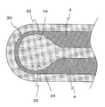
図1に示すように、ヒータ1は、セラミック体2と、セラミック体2に埋設された発熱抵抗体3と、発熱抵抗体3に接続されてセラミック体2の表面に引き出されたリード4とを備えている。 As shown in FIG. 1, the heater 1 includes a ceramic body 2, a heating resistor 3 embedded in the ceramic body 2, and a lead 4 connected to the heating resistor 3 and drawn to the surface of the ceramic body 2. I have it.

ヒータ1におけるセラミック体2は、例えば長手方向を有する棒状に形成されたものである。このセラミック体2には発熱抵抗体3およびリード4が埋設されている。ここで、セラミック体2はセラミックスからなる。これにより急速昇温時の信頼性が高いヒータ1を提供することが可能になる。セラミックスとしては、酸化物セラミックス、窒化物セラミックスまたは炭化物セラミックス等の電気的に絶縁性を有するセラミックスが挙げられる。特に、セラミック体2は、窒化珪素質セラミックスからなっていてもよい。窒化珪素質セラミックスは、主成分である窒化珪素が強度、靱性、絶縁性および耐熱性の観点で優れているからである。 The ceramic body 2 of the heater 1 is formed in a rod shape having a longitudinal direction, for example. A heating resistor 3 and leads 4 are embedded in the ceramic body 2. Here, the ceramic body 2 is made of ceramics. As a result, it is possible to provide the heater 1 having high reliability during rapid temperature rise. Examples of the ceramics include electrically insulating ceramics such as oxide ceramics, nitride ceramics, and carbide ceramics. In particular, the ceramic body 2 may be made of silicon nitride ceramics. This is because silicon nitride-based ceramics is mainly composed of silicon nitride, which is excellent in strength, toughness, insulation and heat resistance.

窒化珪素質セラミックスからなるセラミック体2は、例えば、主成分の窒化珪素に対して、焼結助剤として3〜12質量%のY、YbまたはEr等の希土類元素酸化物、0.5〜3質量%のAlおよび焼結体に含まれるSiO量が1.5〜5質量%となるようにSiOを混合し、所定の形状に成形し、その後、1650〜1780℃でホットプレス焼成することによって得ることができる。セラミック体2の長さは、例えば20〜50mmに設定され、セラミック体2の直径は例えば3〜5mmに設定される。 The ceramic body 2 made of silicon nitride ceramics is, for example, a rare earth element such as Y 2 O 3 , Yb 2 O 3 or Er 2 O 3 in an amount of 3 to 12 mass% as a sintering aid with respect to silicon nitride as a main component. Elemental oxide, 0.5 to 3 mass% of Al 2 O 3 and SiO 2 are mixed so that the amount of SiO 2 contained in the sintered body is 1.5 to 5 mass %, and molded into a predetermined shape. Then, it can be obtained by hot press firing at 1650 to 1780°C. The length of the ceramic body 2 is set to, for example, 20 to 50 mm, and the diameter of the ceramic body 2 is set to, for example, 3 to 5 mm.

なお、セラミック体2として窒化珪素質セラミックスからなるものを用いる場合は、MoSiOまたはWSi等を混合し、分散させてもよい。この場合には、母材である窒化珪素質セラミックスの熱膨張率を発熱抵抗体3の熱膨張率に近付けることができ、ヒータ1の耐久性を向上させることができる。 When the ceramic body 2 made of silicon nitride ceramics is used, MoSiO 2 or WSi 2 may be mixed and dispersed. In this case, the coefficient of thermal expansion of the silicon nitride ceramics, which is the base material, can be brought close to the coefficient of thermal expansion of the heating resistor 3, and the durability of the heater 1 can be improved.

発熱抵抗体3は、セラミック体2の内部に設けられている。発熱抵抗体3はセラミック体2の先端側(一端側)に設けられている。発熱抵抗体3は、電流を流すことによって発熱する部材である。発熱抵抗体3は、セラミック体2の長手方向に沿って伸びる並列部32と、これらを連結する折返し部30とからなる。発熱抵抗体3の形成材料としては、W,MoまたはTiなどの炭化物、窒化物または珪化物などを主成分とするものを使用することができる。セラミック体2が窒化珪素質セラミックスからなる場合は、セラミック体2との熱膨張率の差が小さい点および高い耐熱性を有する点で、上記の材料の中でも炭化タングステン(WC)が発熱抵抗体3の材料として優れている。 The heating resistor 3 is provided inside the ceramic body 2. The heating resistor 3 is provided on the tip side (one end side) of the ceramic body 2. The heating resistor 3 is a member that generates heat by passing an electric current. The heating resistor 3 is composed of a parallel portion 32 extending along the longitudinal direction of the ceramic body 2 and a folded portion 30 connecting them. As a material for forming the heating resistor 3, a material containing a carbide such as W, Mo or Ti, a nitride or a silicide as a main component can be used. When the ceramic body 2 is made of silicon nitride ceramics, tungsten carbide (WC) among the above materials is the heating resistor 3 because of the small difference in coefficient of thermal expansion from the ceramic body 2 and the high heat resistance. It is an excellent material.

さらに、セラミック体2が窒化珪素質セラミックスからなる場合は、発熱抵抗体3は、無機導電体のWCを主成分とし、これに添加される窒化珪素の含有率が20質量%以上であるものが好ましい。例えば、窒化珪素質セラミックスからなるセラミック体2中において、発熱抵抗体3となる導体成分は窒化珪素と比較して熱膨張率が大きいため、通常は引張応力がかかった状態にある。これに対して、発熱抵抗体3中に窒化珪素を添加することにより、熱膨張率をセラミック体2のそれに近付けて、ヒータ1の昇温時および降温時の熱膨張率の差による応力を緩和することができる。 Further, when the ceramic body 2 is made of silicon nitride ceramics, the heating resistor 3 is mainly composed of WC of the inorganic conductor, and the content of silicon nitride added thereto is 20% by mass or more. preferable. For example, in the ceramic body 2 made of silicon nitride ceramics, the conductor component that becomes the heating resistor 3 has a larger coefficient of thermal expansion than silicon nitride, and therefore is usually in a state in which tensile stress is applied. On the other hand, by adding silicon nitride to the heating resistor 3, the coefficient of thermal expansion is brought close to that of the ceramic body 2, and the stress due to the difference in the coefficient of thermal expansion during heating and cooling of the heater 1 is relaxed. can do.

また、発熱抵抗体3に含まれる窒化珪素の含有量が40質量%以下であるときには、発熱抵抗体3の抵抗値のばらつきを小さくさせることができる。従って、発熱抵抗体3に含まれる窒化珪素の含有量は20〜40質量%であることが好ましい。より好ましくは、窒化珪素の含有量は25〜35質量%がよい。また、発熱抵抗体3への同様の添加物として、窒化珪素の代わりに窒化硼素を4〜12質量%添加することもできる。発熱抵抗体3は全長を3〜15mm、断面積を0.15〜0.8mmに設定することができる。 Further, when the content of silicon nitride contained in the heating resistor 3 is 40% by mass or less, the variation in the resistance value of the heating resistor 3 can be reduced. Therefore, the content of silicon nitride contained in the heating resistor 3 is preferably 20 to 40 mass %. More preferably, the content of silicon nitride is 25 to 35% by mass. Further, as a similar additive to the heating resistor 3, boron nitride may be added in an amount of 4 to 12 mass% instead of silicon nitride. The heating resistor 3 can be set to have a total length of 3 to 15 mm and a cross-sectional area of 0.15 to 0.8 mm 2 .

リード4は、発熱抵抗体3と外部の電源とを電気的に接続するための部材である。リード4は、発熱抵抗体3に接続されるとともにセラミック体2の表面に引き出されている。具体的には、発熱抵抗体3の両端部にそれぞれリード4が接合されていて、一方のリード4は、一端が発熱抵抗体3の一端に接続され、他端がセラミック体2の後端寄りの側面から導出され、他方のリード4は、一端が発熱抵抗体3の他端に接続され、他端がセラミック体2の後端部から導出されている。 The lead 4 is a member for electrically connecting the heating resistor 3 and an external power source. The lead 4 is connected to the heating resistor 3 and is drawn out to the surface of the ceramic body 2. Specifically, the leads 4 are joined to both ends of the heating resistor 3, one end of which is connected to one end of the heating resistor 3 and the other end of which is closer to the rear end of the ceramic body 2. The other lead 4 has one end connected to the other end of the heating resistor 3 and the other end led from the rear end of the ceramic body 2.

このリード4は、例えば、発熱抵抗体3と同様の材料を用いて形成される。リード4は、発熱抵抗体3よりも断面積を大きくしたり、セラミック体2の形成材料の含有量を発熱抵抗体3よりも少なくしたりすることによって、単位長さ当たりの抵抗値が低くなっている。特に、WCが、セラミック体2との熱膨張率の差が小さい点、高い耐熱性を有する点および比抵抗が小さい点で、リード4の材料として好適である。また、リード4は無機導電体であるWCを主成分とし、これに窒化珪素を含有量が15質量%以上となるように添加することが好ましい。窒化珪素の含有量が増すにつれて、リード4の熱膨張率を、セラミック体2を構成する窒化珪素の熱膨張率に近付けることができる。また、窒化珪素の含有量が40質量%以下であるときには、リード4の抵抗値が低くなるとともに安定する。従って、窒化珪素の含有量は15〜40質量%が好ましい。より好ましくは、窒化珪素の含有量は20〜35質量%とするのがよい。 The lead 4 is formed using, for example, the same material as that of the heating resistor 3. The lead 4 has a larger cross-sectional area than that of the heating resistor 3 or has a smaller amount of material for forming the ceramic body 2 than that of the heating resistor 3, so that the resistance value per unit length becomes low. ing. In particular, WC is suitable as a material for the lead 4 in that the difference in the coefficient of thermal expansion from the ceramic body 2 is small, the heat resistance is high, and the specific resistance is small. Further, it is preferable that the lead 4 has WC, which is an inorganic conductor, as a main component, and silicon nitride is added to this as a content of 15% by mass or more. As the content of silicon nitride increases, the coefficient of thermal expansion of the lead 4 can be brought closer to the coefficient of thermal expansion of the silicon nitride forming the ceramic body 2. When the content of silicon nitride is 40% by mass or less, the resistance value of the lead 4 becomes low and stable. Therefore, the content of silicon nitride is preferably 15 to 40 mass %. More preferably, the content of silicon nitride is 20 to 35% by mass.

ここで、本実施形態のヒータ1においては、図1に示すように、棒状のセラミック体2と、セラミック体2の内部に設けられた発熱抵抗体3とを備えている。発熱抵抗体3は、対向する2つの並列部32と2つの並列部32を繋ぐ折返し部30とを有する。そして、図2に示すように、折返し部30の伸びる方向に垂直な断面を見たときに折返し部30の内周側に窪み31を有する。 Here, as shown in FIG. 1, the heater 1 of the present embodiment includes a rod-shaped ceramic body 2 and a heating resistor 3 provided inside the ceramic body 2. The heating resistor 3 has two parallel parts 32 facing each other and a folded part 30 connecting the two parallel parts 32. Then, as shown in FIG. 2, when a cross section perpendicular to the extending direction of the folded-back portion 30 is viewed, a recess 31 is provided on the inner peripheral side of the folded-back portion 30.

発熱抵抗体3の折返し部30の断面を見たときに折返し部30の内周側に窪み31を有することによって、ヒータ1の長期信頼性を向上できる。具体的には、折返し部30の内周側にクラックが発生したとしても、上述した窪み31があることによってクラックの進行を窪み31で止めやすくすることができる。そのため、クラックがセラミック体2と発熱抵抗体3との間で拡大してしまうことを低減できる。その結果、ヒータ1の長期信頼性を向上できる。 When the cross section of the folded portion 30 of the heating resistor 3 is viewed, the long-term reliability of the heater 1 can be improved by having the recess 31 on the inner peripheral side of the folded portion 30. Specifically, even if a crack is generated on the inner peripheral side of the folded-back portion 30, the presence of the above-described depression 31 makes it easier to stop the progress of the crack at the depression 31. Therefore, it is possible to reduce the spread of cracks between the ceramic body 2 and the heating resistor 3. As a result, the long-term reliability of the heater 1 can be improved.

発熱抵抗体3の断面形状が窪み31が設けられている部位を除いて楕円形状である場合
(略楕円形状である場合)には、発熱抵抗体3は、折返し部30の伸びる平面上に短軸が位置しており、折返し部30の伸びる平面に垂直な方向に長軸が位置していてもよい。発熱抵抗体3が略楕円形状である場合には、クラックは短軸に沿った方向よりも長軸に沿った方向に進行しやすい。そのため、折返し部30の伸びる平面に垂直な方向に長軸が位置していると、窪み31が長軸方向に沿った方向に進行しようとするクラックを止めやすくなる。
When the cross-sectional shape of the heating resistor 3 is elliptical (except when the recess 31 is provided) (substantially elliptical), the heating resistor 3 is short on the plane in which the folded-back portion 30 extends. The axis may be located, and the major axis may be located in a direction perpendicular to the plane in which the folded portion 30 extends. When the heating resistor 3 has a substantially elliptical shape, cracks are more likely to propagate in the direction along the major axis than in the direction along the minor axis. Therefore, when the major axis is located in the direction perpendicular to the plane in which the folded-back portion 30 extends, it becomes easier for the depression 31 to stop the crack that tends to progress in the direction along the major axis.

また、図3に示すように窪み31が折返し部30の内周に沿って伸びていていてもよい。これにより、窪み31が折返し部30の内周に沿って弧を描くように伸びることになるので、熱応力を分散させやすくすることができる。その結果、ヒータ1の長期信頼性を向上できる。さらに、図4に示すように、窪み31が折返し部30の全周に沿って伸びていてもよい。これにより、窪み31の端部が折返し部30の途中に位置してしまい、この端部を起点としたクラックが生じるおそれを低減できる。その結果、折返し部30の特定の部位に熱応力が集中するおそれを低減できる。 Further, as shown in FIG. 3, the depression 31 may extend along the inner circumference of the folded-back portion 30. As a result, the depression 31 extends along the inner circumference of the folded-back portion 30 so as to draw an arc, so that the thermal stress can be easily dispersed. As a result, the long-term reliability of the heater 1 can be improved. Further, as shown in FIG. 4, the depression 31 may extend along the entire circumference of the folded portion 30. As a result, it is possible to reduce the risk that the end of the recess 31 is located in the middle of the folded portion 30 and a crack starting from this end is generated. As a result, it is possible to reduce the risk that thermal stress concentrates on a specific portion of the folded portion 30.

また、図5に示すように、窪み31が折返し部30の頂部(最も先端に位置する部位)の内周側に位置していてもよい。折返し部30のうち最も応力が集中しやすい位置、すなわち、最もクラックが生じやすい位置に窪み31が位置していることによって、クラックの進行を低減しやすくできる。 Further, as shown in FIG. 5, the depression 31 may be located on the inner peripheral side of the top portion (the portion located at the most tip) of the folded portion 30. Since the depression 31 is located at the position where the stress is most likely to be concentrated in the folded-back portion 30, that is, the position where the crack is most likely to occur, the progress of the crack can be easily reduced.

また、図5に示すように、折返し部30の伸びる方向に垂直な断面における窪み31の深さが頂部(D−D’線が通る部位)において最も大きくなっていてもよい。応力が集中しやすい頂部において窪み31を深くしておくことによって、クラックの進行を低減しやすくできる。 Further, as shown in FIG. 5, the depth of the depression 31 in the cross section perpendicular to the extending direction of the folded-back portion 30 may be the largest at the top portion (portion through which the D-D′ line passes). By making the depression 31 deep at the top where stress is likely to concentrate, the progress of cracks can be easily reduced.

特に、図6のうちD−D’線で切った断面に示すように、窪み31の深さが発熱抵抗体3の幅(内周と外周との間隔の最大値)の1/2よりも大きい部分があってもよい。この場合には、窪み31が折返し部30の断面の中心に位置するようになるので、折返し部30の内側と外側とにセラミック体2が位置することになる。そのため、折返し部30が熱膨張したときに、外側だけではなく内側にも熱膨張によって生じる力を逃がすことができる。その結果、ヒータ1におけるクラックの発生を低減できる。 In particular, as shown in the cross section taken along the line DD' in FIG. 6, the depth of the recess 31 is less than 1/2 of the width of the heating resistor 3 (the maximum value of the distance between the inner circumference and the outer circumference). There may be a large part. In this case, since the depression 31 comes to be located at the center of the cross section of the folded portion 30, the ceramic body 2 is located inside and outside the folded portion 30. Therefore, when the folded-back portion 30 thermally expands, the force generated by the thermal expansion can be released not only to the outside but also to the inside. As a result, the occurrence of cracks in the heater 1 can be reduced.

また、折返し部30の伸びる方向に垂直な断面における窪み31の深さが頂部から離れるにつれて小さくなっていてもよい。これにより、窪み31の深さを徐々に小さくしていくことができるので、窪み31の端部において大きな段差が生じてしまうおそれを低減できる。これにより、窪み31の端部を起点としたクラックが生じるおそれを低減できる。 Further, the depth of the depression 31 in the cross section perpendicular to the extending direction of the folded-back portion 30 may decrease with increasing distance from the top. As a result, the depth of the recess 31 can be gradually reduced, and thus it is possible to reduce the possibility that a large step is formed at the end of the recess 31. As a result, it is possible to reduce the risk of cracks originating from the end of the depression 31.

また、図7に示すように、窪み31が2つの並列部32にまで伸びていてもよい。窪み31が並列部32にまで伸びて形成されていることによって、窪み31の端部を折返し部30の外に位置させることができる。その結果、折返し部30において熱応力が集中するおそれを低減できる。 Further, as shown in FIG. 7, the depression 31 may extend to the two parallel portions 32. Since the recess 31 is formed to extend to the parallel portion 32, the end of the recess 31 can be located outside the folded portion 30. As a result, it is possible to reduce the risk that thermal stress is concentrated in the folded portion 30.

折返し部30の伸びる方向に垂直な断面を見たときに窪み31の底面が曲線状であってもよい。これにより、折返し部30の窪み31において応力が集中するおそれを低減できる。その結果、急速昇温可能なヒータ1とすることができる。 The bottom surface of the recess 31 may be curved when the cross section perpendicular to the extending direction of the folded portion 30 is viewed. This can reduce the risk of stress concentration in the depression 31 of the folded-back portion 30. As a result, the heater 1 capable of rapidly raising the temperature can be obtained.

また、図8に示すように、折返し部30の外周側にも第2窪み33があってもよい。これにより、クラックの進行をさらにしにくくすることができる。第2窪み33は、第2窪み33と窪み31との間に折返し部30の断面の中心が来るように位置していてもよい。これにより、折返し部30の内周側と外周側とで生じる熱応力のばらつきを低減できる。
そのため、ヒータ1にクラックが生じるおそれを低減できる。
Further, as shown in FIG. 8, a second recess 33 may be provided on the outer peripheral side of the folded-back portion 30. As a result, the progress of cracks can be made more difficult. The second recess 33 may be positioned such that the center of the cross section of the folded portion 30 is located between the second recess 33 and the recess 31. As a result, it is possible to reduce variations in thermal stress generated on the inner peripheral side and the outer peripheral side of the folded portion 30.
Therefore, it is possible to reduce the risk of cracks in the heater 1.

また、図9に示すように、窪み31の一部が発熱抵抗体3を貫通していてもよい。発熱抵抗体3に突入電流が流れたときには、瞬間的に発熱抵抗体3にいびつな温度分布が生じるおそれがあり、この際に発熱抵抗体2にねじれるような熱膨張が生じるおそれがある。窪み31の一部が発熱抵抗体を貫通していることによって、ねじれるような熱膨張が生じようとしたときに、この熱応力を低減することができる。 Further, as shown in FIG. 9, a part of the depression 31 may penetrate the heating resistor 3. When a rush current flows through the heating resistor 3, a distorted temperature distribution may occur instantaneously in the heating resistor 3, and at this time, the thermal expansion may occur in the heating resistor 2 such that the heating resistor 2 is twisted. Since a part of the recess 31 penetrates the heating resistor, when thermal expansion such as twisting is about to occur, this thermal stress can be reduced.

また、図10に示すように、2つの並列部32を含む断面で見たときに2つの並列部32の少なくとも一方が凹部34を有していてもよい。凹部34は、2つの並列部32を含む平面に対して垂直な方向に伸びている。言い換えると、凹部34は、並列部32を、2つの並列部32を含む平面に対して垂直な方向に貫いている。そして、窪み31が凹部34の内周面にまで伸びていてもよい。これにより、折返し部30で生じた熱応力を並列部32の凹部34にまで伝えるとともに、この凹部34で分散させることができる。 Further, as shown in FIG. 10, at least one of the two parallel portions 32 may have a recess 34 when viewed in a cross section including the two parallel portions 32. The concave portion 34 extends in a direction perpendicular to the plane including the two parallel portions 32. In other words, the concave portion 34 penetrates the parallel portion 32 in a direction perpendicular to the plane including the two parallel portions 32. The recess 31 may extend to the inner peripheral surface of the recess 34. Thereby, the thermal stress generated in the folded portion 30 can be transmitted to the concave portion 34 of the parallel portion 32 and can be dispersed in the concave portion 34.

図11に示すように、グロープラグ10は、上述のヒータ1と、ヒータ1の後端側(他端側)を覆うように取り付けられた筒状の金属筒5とを備えている。また、金属筒5の内側に配置されてヒータ1の後端に取り付けられた電極金具6を備えている。グロープラグ10によれば、上述のヒータ1を使用していることから、耐久性が向上している。 As shown in FIG. 11, the glow plug 10 includes the above-described heater 1 and a tubular metal tube 5 attached so as to cover the rear end side (the other end side) of the heater 1. Further, an electrode fitting 6 is provided inside the metal tube 5 and attached to the rear end of the heater 1. According to the glow plug 10, since the heater 1 described above is used, the durability is improved.

金属筒5は、セラミック体2を保持するための部材である。金属筒5は、筒状の部材であって、セラミック体2の後端側を囲むように取り付けられている。すなわち、筒状の金属筒5の内側に棒状のセラミック体2が挿入されている。金属筒5は、セラミック体2の後端側の側面に設けられてリード4が露出している部分に電気的に接続されている。金属筒5は、例えば、ステンレスまたは鉄(Fe)−ニッケル(Ni)−コバルト(Co)合金からなる。 The metal tube 5 is a member for holding the ceramic body 2. The metal cylinder 5 is a cylindrical member and is attached so as to surround the rear end side of the ceramic body 2. That is, the rod-shaped ceramic body 2 is inserted inside the cylindrical metal cylinder 5. The metal tube 5 is provided on the side surface on the rear end side of the ceramic body 2 and is electrically connected to a portion where the leads 4 are exposed. The metal cylinder 5 is made of, for example, stainless steel or an iron (Fe)-nickel (Ni)-cobalt (Co) alloy.

金属筒5とセラミック体2とは、ろう材によって接合されている。ろう材は、金属筒5とセラミック体2との間にセラミック体2の後端側を囲むように設けられている。このろう材が設けられていることによって、金属筒5とリード4とが電気的に接続されている。 The metal tube 5 and the ceramic body 2 are joined by a brazing material. The brazing material is provided between the metal cylinder 5 and the ceramic body 2 so as to surround the rear end side of the ceramic body 2. By providing this brazing material, the metal tube 5 and the lead 4 are electrically connected.

ろう材としては、ガラス成分を5〜20質量%含んだ銀(Ag)−銅(Cu)ろう、AgろうまたはCuろう等を用いることができる。ガラス成分はセラミック体2のセラミックスとの濡れ性が良く、摩擦係数が大きいために、ろう材とセラミック体2との接合強度またはろう材と金属筒5との接合強度を向上させることができる。 As the brazing material, silver (Ag)-copper (Cu) brazing, Ag brazing or Cu brazing containing 5 to 20 mass% of a glass component can be used. The glass component has good wettability with the ceramic of the ceramic body 2 and has a large friction coefficient, so that the bonding strength between the brazing material and the ceramic body 2 or the bonding strength between the brazing material and the metal cylinder 5 can be improved.

電極金具6は、金属筒5の内側に位置してセラミック体2の後端にリード4に電気的に接続するように取り付けられている。電極金具6は、種々の形態のものを用いることができるが、図12に示す例では、セラミック体2の後端にリード4を含んで被さるように取り付けられるキャップ部と外部の接続電極に電気的に接続されるコイル状部とが線状部で接続された構成である。この電極金具6は、金属筒5との間で短絡が生じないように金属筒5の内周面から離れて保持されている。 The electrode fitting 6 is located inside the metal cylinder 5 and is attached to the rear end of the ceramic body 2 so as to be electrically connected to the lead 4. Various types of electrode fittings 6 can be used, but in the example shown in FIG. 12, the cap portion attached so as to cover the rear end of the ceramic body 2 including the lead 4 and the external connection electrode are electrically connected. The coil-shaped portion to be electrically connected is connected by a linear portion. The electrode fitting 6 is held away from the inner peripheral surface of the metal cylinder 5 so as not to cause a short circuit with the metal cylinder 5.

電極金具6は、外部の電源との接続における応力緩和のために設けられたコイル状部を有する金属線である。電極金具6は、リード4に電気的に接続されるとともに、外部の電源と電気的に接続される。外部の電源によって金属筒5と電極金具6との間に電圧を加えることによって、金属筒5および電極金具6を介して発熱抵抗体3に電流を流すことができる。電極金具6は、例えばニッケルまたはステンレスからなる。ヒータ1は、例えば、上記構成の発熱抵抗体3、リード4およびセラミック体2の形状の金型を用いた射出成形法等によって形成することができる。 The electrode fitting 6 is a metal wire having a coil-shaped portion provided for stress relaxation in connection with an external power source. The electrode fitting 6 is electrically connected to the lead 4 and also to an external power source. By applying a voltage between the metal cylinder 5 and the electrode fitting 6 by an external power source, a current can be passed through the heating resistor 3 via the metal cylinder 5 and the electrode fitting 6. The electrode fitting 6 is made of nickel or stainless steel, for example. The heater 1 can be formed by, for example, an injection molding method or the like using a die having the shape of the heating resistor 3, the lead 4 and the ceramic body 2 having the above-described configuration.

1:ヒータ
2:セラミック体
3:発熱抵抗体
30:折返し部
31:窪み
32:並列部
33:第2窪み
34:凹部
4:リード
5:金属筒
6:電極金具
10:グロープラグ
1: Heater 2: Ceramic body 3: Heating resistor 30: Folding part 31: Dimple 32: Parallel part 33: Second dimple 34: Recess 4: Lead 5: Metal cylinder 6: Electrode metal fitting 10: Glow plug

Claims (10)

棒状のセラミック体と、該セラミック体の内部に設けられた発熱抵抗体とを備えており、該発熱抵抗体は、対向する2つの並列部と該2つの並列部を繋ぐ折返し部とを有するとともに、該折返し部の伸びる方向に垂直な断面を見たときに前記折返し部の内周側に窪みを有し、
前記2つの並列部を含む断面で見たときに、
前記2つの並列部は、それぞれの内周側および外周側に直線状の部位を有し、
前記2つの並列部は、少なくとも一方の内周側に凹部を有するとともに、前記窪みが前記凹部の内周面にまで伸びているヒータ。
The heating element includes a rod-shaped ceramic body and a heating resistor provided inside the ceramic body. The heating resistor has two parallel portions facing each other and a folded portion connecting the two parallel portions. , have a recess on the inner peripheral side of the folded portion when viewed cross-section perpendicular to the extending direction of the該折return part,
When viewed in a cross section including the two parallel portions,
The two parallel portions have linear portions on the inner peripheral side and the outer peripheral side, respectively,
The two parallel portions have a recess on at least one inner peripheral side, and the recess extends to the inner peripheral surface of the recess .
前記窪みが前記折返し部の内周に沿って伸びている請求項1に記載のヒータ。 The heater according to claim 1, wherein the recess extends along the inner circumference of the folded portion. 前記窪みが前記折返し部の頂部の内周側に位置している請求項2に記載のヒータ。 The heater according to claim 2, wherein the recess is located on the inner peripheral side of the top of the folded portion. 前記折返し部の伸びる方向に垂直な断面における前記窪みの深さが前記頂部において最も大きくなっている請求項3に記載のヒータ。 The heater according to claim 3, wherein the depth of the recess in the cross section perpendicular to the extending direction of the folded portion is the largest at the top. 前記折返し部の伸びる方向に垂直な断面における前記窪みの深さが前記頂部から離れるにつれて小さくなっている請求項4に記載のヒータ。 The heater according to claim 4, wherein the depth of the recess in a cross section perpendicular to the extending direction of the folded-back portion decreases as the distance from the top portion increases. 前記窪みが前記2つの並列部にまで伸びている請求項1乃至請求項のいずれかに記載のヒータ。 The heater according to any one of claims 1 to 5 wherein the recess extends to said two parallel portions. 該折返し部の伸びる方向に垂直な断面を見たときに前記窪みの底面が曲線状である請求項1乃至請求項のいずれかに記載のヒータ。 The heater according to any one of claims 1 to 6 , wherein the bottom surface of the recess has a curved shape when the cross section perpendicular to the extending direction of the folded portion is viewed. 前記窪みの一部が前記発熱抵抗体を貫通している請求項1乃至請求項のいずれかに記載のヒータ。 The heater according to any one of claims 1 to 7 a part of the recess extends through the heating resistor. 前記折返し部の外周側に第2窪みを有する請求項1乃至請求項8のいずれかに記載のヒータ。The heater according to any one of claims 1 to 8, which has a second recess on the outer peripheral side of the folded portion. 請求項1乃至請求項9のいずれかに記載のヒータであって前記発熱抵抗体が前記セラミック体の一端側に位置しているヒータと、前記セラミック体の他端側を覆うように取り付
けられた金属筒とを備えたグロープラグ。
The heater according to any one of claims 1 to 9, wherein the heating resistor is attached so as to cover the heater located on one end side of the ceramic body and the other end side of the ceramic body. Glow plug with metal tube.
JP2016107116A 2016-05-30 2016-05-30 Heater and glow plug equipped with the same Active JP6711697B2 (en)

Priority Applications (2)

Application Number Priority Date Filing Date Title
JP2016107116A JP6711697B2 (en) 2016-05-30 2016-05-30 Heater and glow plug equipped with the same
DE102017111549.8A DE102017111549A1 (en) 2016-05-30 2017-05-26 HEATER AND GLOW CANDLE WITH THE HEATER

Applications Claiming Priority (1)

Application Number Priority Date Filing Date Title
JP2016107116A JP6711697B2 (en) 2016-05-30 2016-05-30 Heater and glow plug equipped with the same

Publications (2)

Publication Number Publication Date
JP2017216045A JP2017216045A (en) 2017-12-07
JP6711697B2 true JP6711697B2 (en) 2020-06-17

Family

ID=60268812

Family Applications (1)

Application Number Title Priority Date Filing Date
JP2016107116A Active JP6711697B2 (en) 2016-05-30 2016-05-30 Heater and glow plug equipped with the same

Country Status (2)

Country Link
JP (1) JP6711697B2 (en)
DE (1) DE102017111549A1 (en)

Family Cites Families (4)

* Cited by examiner, † Cited by third party
Publication number Priority date Publication date Assignee Title
JPS6244975A (en) * 1985-08-22 1987-02-26 株式会社デンソー Ceramic heater
JP3924193B2 (en) * 2001-05-02 2007-06-06 日本特殊陶業株式会社 Ceramic heater, glow plug using the same, and method for manufacturing ceramic heater
EP2496051B1 (en) * 2009-10-27 2017-01-04 Kyocera Corporation Ceramic heater
JP6199951B2 (en) * 2015-12-24 2017-09-20 京セラ株式会社 Heater and glow plug equipped with the same

Also Published As

Publication number Publication date
JP2017216045A (en) 2017-12-07
DE102017111549A1 (en) 2017-11-30

Similar Documents

Publication Publication Date Title
JP5436675B2 (en) Heater and glow plug equipped with the same
JP5575260B2 (en) Heater and glow plug equipped with the same
JP6023389B1 (en) Heater and glow plug equipped with the same
JP6592103B2 (en) Heater and glow plug equipped with the same
JP6711697B2 (en) Heater and glow plug equipped with the same
JP6603321B2 (en) Heater and glow plug equipped with the same
JP6725653B2 (en) Heater and glow plug equipped with the same
JP7116237B2 (en) heater
JP6105464B2 (en) Heater and glow plug equipped with the same
JP6538467B2 (en) Heater and glow plug
WO2017135362A1 (en) Heater and glow-plug provided therewith
JP7199448B2 (en) Heater and glow plug with same
JP5726311B2 (en) Heater and glow plug equipped with the same
JP7162558B2 (en) Heater and glow plug with same
JP6817325B2 (en) Heater and glow plug with it
JP6878116B2 (en) Heater and glow plug with it
JP6923425B2 (en) heater
JP6204566B2 (en) Heater and glow plug

Legal Events

Date Code Title Description
A621 Written request for application examination

Free format text: JAPANESE INTERMEDIATE CODE: A621

Effective date: 20190311

A977 Report on retrieval

Free format text: JAPANESE INTERMEDIATE CODE: A971007

Effective date: 20200122

A131 Notification of reasons for refusal

Free format text: JAPANESE INTERMEDIATE CODE: A131

Effective date: 20200128

A521 Written amendment

Free format text: JAPANESE INTERMEDIATE CODE: A523

Effective date: 20200327

TRDD Decision of grant or rejection written
A01 Written decision to grant a patent or to grant a registration (utility model)

Free format text: JAPANESE INTERMEDIATE CODE: A01

Effective date: 20200428

A61 First payment of annual fees (during grant procedure)

Free format text: JAPANESE INTERMEDIATE CODE: A61

Effective date: 20200528

R150 Certificate of patent or registration of utility model

Ref document number: 6711697

Country of ref document: JP

Free format text: JAPANESE INTERMEDIATE CODE: R150