JP6711600B2 - Light source device and information acquisition device - Google Patents
Light source device and information acquisition device Download PDFInfo
- Publication number
- JP6711600B2 JP6711600B2 JP2015240266A JP2015240266A JP6711600B2 JP 6711600 B2 JP6711600 B2 JP 6711600B2 JP 2015240266 A JP2015240266 A JP 2015240266A JP 2015240266 A JP2015240266 A JP 2015240266A JP 6711600 B2 JP6711600 B2 JP 6711600B2
- Authority
- JP
- Japan
- Prior art keywords
- light
- fiber
- light source
- resonator
- pulsed light
- Prior art date
- Legal status (The legal status is an assumption and is not a legal conclusion. Google has not performed a legal analysis and makes no representation as to the accuracy of the status listed.)
- Active
Links
Images


Classifications
-
- H—ELECTRICITY
- H01—ELECTRIC ELEMENTS
- H01S—DEVICES USING THE PROCESS OF LIGHT AMPLIFICATION BY STIMULATED EMISSION OF RADIATION [LASER] TO AMPLIFY OR GENERATE LIGHT; DEVICES USING STIMULATED EMISSION OF ELECTROMAGNETIC RADIATION IN WAVE RANGES OTHER THAN OPTICAL
- H01S3/00—Lasers, i.e. devices using stimulated emission of electromagnetic radiation in the infrared, visible or ultraviolet wave range
- H01S3/05—Construction or shape of optical resonators; Accommodation of active medium therein; Shape of active medium
- H01S3/06—Construction or shape of active medium
- H01S3/063—Waveguide lasers, i.e. whereby the dimensions of the waveguide are of the order of the light wavelength
- H01S3/067—Fibre lasers
- H01S3/06708—Constructional details of the fibre, e.g. compositions, cross-section, shape or tapering
- H01S3/06725—Fibre characterized by a specific dispersion, e.g. for pulse shaping in soliton lasers or for dispersion compensating [DCF]
-
- H—ELECTRICITY
- H01—ELECTRIC ELEMENTS
- H01S—DEVICES USING THE PROCESS OF LIGHT AMPLIFICATION BY STIMULATED EMISSION OF RADIATION [LASER] TO AMPLIFY OR GENERATE LIGHT; DEVICES USING STIMULATED EMISSION OF ELECTROMAGNETIC RADIATION IN WAVE RANGES OTHER THAN OPTICAL
- H01S3/00—Lasers, i.e. devices using stimulated emission of electromagnetic radiation in the infrared, visible or ultraviolet wave range
- H01S3/10—Controlling the intensity, frequency, phase, polarisation or direction of the emitted radiation, e.g. switching, gating, modulating or demodulating
- H01S3/11—Mode locking; Q-switching; Other giant-pulse techniques, e.g. cavity dumping
- H01S3/1106—Mode locking
- H01S3/1112—Passive mode locking
- H01S3/1115—Passive mode locking using intracavity saturable absorbers
- H01S3/1118—Semiconductor saturable absorbers, e.g. semiconductor saturable absorber mirrors [SESAMs]; Solid-state saturable absorbers, e.g. carbon nanotube [CNT] based
-
- H—ELECTRICITY
- H01—ELECTRIC ELEMENTS
- H01S—DEVICES USING THE PROCESS OF LIGHT AMPLIFICATION BY STIMULATED EMISSION OF RADIATION [LASER] TO AMPLIFY OR GENERATE LIGHT; DEVICES USING STIMULATED EMISSION OF ELECTROMAGNETIC RADIATION IN WAVE RANGES OTHER THAN OPTICAL
- H01S3/00—Lasers, i.e. devices using stimulated emission of electromagnetic radiation in the infrared, visible or ultraviolet wave range
- H01S3/005—Optical devices external to the laser cavity, specially adapted for lasers, e.g. for homogenisation of the beam or for manipulating laser pulses, e.g. pulse shaping
- H01S3/0057—Temporal shaping, e.g. pulse compression, frequency chirping
-
- H—ELECTRICITY
- H01—ELECTRIC ELEMENTS
- H01S—DEVICES USING THE PROCESS OF LIGHT AMPLIFICATION BY STIMULATED EMISSION OF RADIATION [LASER] TO AMPLIFY OR GENERATE LIGHT; DEVICES USING STIMULATED EMISSION OF ELECTROMAGNETIC RADIATION IN WAVE RANGES OTHER THAN OPTICAL
- H01S3/00—Lasers, i.e. devices using stimulated emission of electromagnetic radiation in the infrared, visible or ultraviolet wave range
- H01S3/005—Optical devices external to the laser cavity, specially adapted for lasers, e.g. for homogenisation of the beam or for manipulating laser pulses, e.g. pulse shaping
- H01S3/0092—Nonlinear frequency conversion, e.g. second harmonic generation [SHG] or sum- or difference-frequency generation outside the laser cavity
-
- H—ELECTRICITY
- H01—ELECTRIC ELEMENTS
- H01S—DEVICES USING THE PROCESS OF LIGHT AMPLIFICATION BY STIMULATED EMISSION OF RADIATION [LASER] TO AMPLIFY OR GENERATE LIGHT; DEVICES USING STIMULATED EMISSION OF ELECTROMAGNETIC RADIATION IN WAVE RANGES OTHER THAN OPTICAL
- H01S3/00—Lasers, i.e. devices using stimulated emission of electromagnetic radiation in the infrared, visible or ultraviolet wave range
- H01S3/05—Construction or shape of optical resonators; Accommodation of active medium therein; Shape of active medium
- H01S3/06—Construction or shape of active medium
- H01S3/063—Waveguide lasers, i.e. whereby the dimensions of the waveguide are of the order of the light wavelength
- H01S3/067—Fibre lasers
- H01S3/06754—Fibre amplifiers
-
- H—ELECTRICITY
- H01—ELECTRIC ELEMENTS
- H01S—DEVICES USING THE PROCESS OF LIGHT AMPLIFICATION BY STIMULATED EMISSION OF RADIATION [LASER] TO AMPLIFY OR GENERATE LIGHT; DEVICES USING STIMULATED EMISSION OF ELECTROMAGNETIC RADIATION IN WAVE RANGES OTHER THAN OPTICAL
- H01S3/00—Lasers, i.e. devices using stimulated emission of electromagnetic radiation in the infrared, visible or ultraviolet wave range
- H01S3/05—Construction or shape of optical resonators; Accommodation of active medium therein; Shape of active medium
- H01S3/06—Construction or shape of active medium
- H01S3/063—Waveguide lasers, i.e. whereby the dimensions of the waveguide are of the order of the light wavelength
- H01S3/067—Fibre lasers
- H01S3/06791—Fibre ring lasers
-
- H—ELECTRICITY
- H01—ELECTRIC ELEMENTS
- H01S—DEVICES USING THE PROCESS OF LIGHT AMPLIFICATION BY STIMULATED EMISSION OF RADIATION [LASER] TO AMPLIFY OR GENERATE LIGHT; DEVICES USING STIMULATED EMISSION OF ELECTROMAGNETIC RADIATION IN WAVE RANGES OTHER THAN OPTICAL
- H01S3/00—Lasers, i.e. devices using stimulated emission of electromagnetic radiation in the infrared, visible or ultraviolet wave range
- H01S3/05—Construction or shape of optical resonators; Accommodation of active medium therein; Shape of active medium
- H01S3/08—Construction or shape of optical resonators or components thereof
- H01S3/08018—Mode suppression
- H01S3/08022—Longitudinal modes
- H01S3/08027—Longitudinal modes by a filter, e.g. a Fabry-Perot filter is used for wavelength setting
-
- H—ELECTRICITY
- H01—ELECTRIC ELEMENTS
- H01S—DEVICES USING THE PROCESS OF LIGHT AMPLIFICATION BY STIMULATED EMISSION OF RADIATION [LASER] TO AMPLIFY OR GENERATE LIGHT; DEVICES USING STIMULATED EMISSION OF ELECTROMAGNETIC RADIATION IN WAVE RANGES OTHER THAN OPTICAL
- H01S3/00—Lasers, i.e. devices using stimulated emission of electromagnetic radiation in the infrared, visible or ultraviolet wave range
- H01S3/14—Lasers, i.e. devices using stimulated emission of electromagnetic radiation in the infrared, visible or ultraviolet wave range characterised by the material used as the active medium
- H01S3/16—Solid materials
- H01S3/1601—Solid materials characterised by an active (lasing) ion
- H01S3/1603—Solid materials characterised by an active (lasing) ion rare earth
- H01S3/1618—Solid materials characterised by an active (lasing) ion rare earth ytterbium
Description
本発明は、広帯域光源等の光源装置、及びこれを有する情報取得装置に関する。 The present invention relates to a light source device such as a broadband light source, and an information acquisition device including the light source device.
近年、医用イメージング装置用のコヒーレント広帯域光源(光源装置)として、高非線形光ファイバーによる非線形波長変換技術を利用した広帯域光源の研究が盛んに行われている。このような広帯域光源が用いられる医用イメージング装置としては、スペクトル・エンコード内視鏡(spectrally encoded endoscopy)が例示される。また、光コヒーレント・トモグラフィー(optical coherent tomography)も例示される。 2. Description of the Related Art In recent years, as a coherent broadband light source (light source device) for a medical imaging device, research on a broadband light source using a nonlinear wavelength conversion technology using a highly nonlinear optical fiber has been actively conducted. An example of a medical imaging apparatus in which such a broadband light source is used is a spectrally encoded endoscopy. Moreover, optical coherent tomography is also exemplified.
高非線形光ファイバーの中を強度の強い光が伝搬すると、高非線形光ファイバーの非線形光学効果によって、伝搬する光は、広帯域の波長帯を有する広帯域光であるスーパーコンティニューム光(以下、SC光と呼ぶ)に変換される。このような波長の変換に用いられる高非線形光ファイバーとしては、光ファイバーのコア及びクラッドに周期的な微細加工を施したフォトニック結晶ファイバーが用いられることがある。フォトニック結晶ファイバーのコア及びクラッドには周期的な微細加工が施されている。この構造によって、フォトニック結晶ファイバーのコア内に強い光を閉じ込めることが可能となり、コア内に効率的な波長変換に必要な高い光密度を得ることができる。 When high-intensity light propagates in a highly nonlinear optical fiber, the propagating light is supercontinuum light (hereinafter, referred to as SC light), which is broadband light having a broadband wavelength band due to the nonlinear optical effect of the highly nonlinear optical fiber. Is converted to. As a highly nonlinear optical fiber used for such wavelength conversion, a photonic crystal fiber in which the core and the clad of the optical fiber are subjected to periodic fine processing may be used. The core and the clad of the photonic crystal fiber are subjected to periodic fine processing. With this structure, it is possible to confine strong light in the core of the photonic crystal fiber, and it is possible to obtain a high light density required for efficient wavelength conversion in the core.
また、フォトニック結晶ファイバーの微細加工の形状を変えることにより、フォトニック結晶ファイバーの分散を制御することができる。一般的に効率的なSC光の発生を行うためには、高非線形光ファイバーに入射される光の波長が、高非線形ファイバーのゼロ分散波長の近傍であり、かつ異常分散を有する波長であることが望ましい。周期的な微細加工が施されたフォトニック結晶ファイバーは、周期的な微細加工が施されていないファイバーよりも分散の調整が容易である。そのため、入射する光の波長を考慮して適切な構造を有するフォトニック結晶ファイバーを選択することにより、効率的なSC光の発生が可能となる。 Moreover, the dispersion of the photonic crystal fiber can be controlled by changing the shape of the microfabrication of the photonic crystal fiber. Generally, in order to efficiently generate SC light, the wavelength of light incident on the highly nonlinear fiber must be near the zero dispersion wavelength of the highly nonlinear fiber and have a wavelength with anomalous dispersion. desirable. Photonic crystal fibers that have been subjected to periodic fine processing have easier dispersion adjustment than fibers that have not been subjected to periodic fine processing. Therefore, it is possible to efficiently generate SC light by selecting a photonic crystal fiber having an appropriate structure in consideration of the wavelength of incident light.
フォトニック結晶ファイバーに入射する光としては、パルス幅が100ps以下のモード同期パルス光が用いられ得る。パルス幅が100ps以下のパルス光を用いた場合、非線形光学効果を生じさせるのに必要となる、高いピーク強度の光を得ることが容易となる。また、モード同期パルス光を用いた場合、多様な非線形光学効果によって伝搬する光の波長を広帯域化することができる。広帯域化に寄与する非線形光学効果としては、自己位相変調(self phase modulation)、ソリトン分割(soliton fission)、ソリトン自己周波数シフト(soliton self frequency shift)が例示される。また、非ソリトン放射(non-solitonic radiation)、パルストラッピング(pulse trapping)が例示される。 Mode-locked pulsed light having a pulse width of 100 ps or less can be used as the light incident on the photonic crystal fiber. When pulsed light having a pulse width of 100 ps or less is used, it becomes easy to obtain light having a high peak intensity, which is necessary for producing a nonlinear optical effect. Moreover, when mode-locked pulsed light is used, the wavelength of light propagating can be broadened by various nonlinear optical effects. Examples of non-linear optical effects that contribute to widening the band include self phase modulation, soliton division, and soliton self frequency shift. Further, non-solitonic radiation and pulse trapping are exemplified.
なお、フォトニック結晶ファイバーを伝搬するパルス光によって生じるSC光の発生メカニズムは、非特許文献1−3に記載されている。また、SC光を発生させる共振器型の広帯域光源の例が特許文献1に記載されている。
The generation mechanism of SC light generated by the pulsed light propagating in the photonic crystal fiber is described in Non-Patent Documents 1-3.
SC光を発生させる光源装置において、分散補償光学系を有するものがある。このような光源装置においては、分散補償光学系を備えることにより、光源の大型化、部品アライメントの煩雑さ、アライメントずれによる光源の不安定性といった課題が生じ得る。 Some light source devices that generate SC light have a dispersion compensation optical system. In such a light source device, the provision of the dispersion compensation optical system may cause problems such as an increase in size of the light source, complexity of component alignment, and instability of the light source due to misalignment.
本発明は、分散補償光学系を用いることなくSC光を発生し得る光源装置を提供することを目的とする。 An object of the present invention is to provide a light source device that can generate SC light without using a dispersion compensation optical system.
本発明の一側面に係る光源装置は、パルス光を生成する共振器を有するファイバーレーザと、前記ファイバーレーザから射出される前記パルス光を増幅して射出する増幅器と、前記増幅器で増幅される前記パルス光が通過する際に、非線形効果を発生させる非線形ファイバーと、を有し、前記共振器の群遅延分散をD1、前記共振器の出力端と前記非線形ファイバーの入力端との間の群遅延分散をD2としたとき、群遅延分散D1及び群遅延分散D2はともに正の値であり、真空中の光速をc、前記ファイバーレーザより射出される前記パルス光のスペクトル半値全幅をΔλ、前記ファイバーレーザより射出される前記パルス光の中心波長をλ、前記パルス光の形状に基づく係数をaとし、

分散補償光学系を用いることなくSC光を発生し得る光源装置が提供される。 Provided is a light source device capable of generating SC light without using a dispersion compensation optical system.
(比較例)
本発明の実施形態に係る広帯域光源を説明するに先立ち、比較例に係る広帯域光源について図11を用いて説明する。
(Comparative example)
Prior to describing the broadband light source according to the embodiment of the present invention, a broadband light source according to a comparative example will be described with reference to FIG. 11.
フォトニック結晶ファイバーにパルス光を入射してSC光を発生させる広帯域光源において、イッテルビウム元素(Yb)がドープされた光ファイバー(Ybドープファイバー)を利得媒体として用いるものがある。このような広帯域光源は、波長1μm近傍のパルス光をフォトニック結晶ファイバーに入射させることにより、SC光を発生させることができる。入射させるパルス光の波長(約1μm)が可視光に近いため、Ybドープファイバーを用いた広帯域光源は可視光を含むSC光の発生に適している。 In a broadband light source that generates pulsed light by injecting pulsed light into a photonic crystal fiber, there is one that uses an optical fiber (Yb-doped fiber) doped with ytterbium element (Yb) as a gain medium. Such a broadband light source can generate SC light by making pulsed light having a wavelength of about 1 μm incident on the photonic crystal fiber. Since the wavelength (about 1 μm) of the incident pulsed light is close to visible light, the broadband light source using the Yb-doped fiber is suitable for generating SC light including visible light.
一般的に広く用いられているシングルモードファイバー及びマルチモードファイバーは、シリカガラスの分散特性と似た分散特性を有している。そのため、波長1μm近傍のパルス光が光ファイバーを伝搬する場合、光ファイバーの正常分散(群速度分散が正の値である分散)によって伝搬するパルス光のパルス幅が広がる。このパルス幅の広がりを抑えるために、Ybドープファイバーを用いた広帯域光源は、光ファイバーの分散を補償してパルス幅を小さくする分散補償光学系を備えている場合が多い。ここで分散補償光学系とは、波長1μm近傍の光に対して、その群遅延分散が負である光学系(又は光学部品)を指す。 The generally widely used single mode fibers and multimode fibers have dispersion characteristics similar to those of silica glass. Therefore, when pulsed light having a wavelength of about 1 μm propagates through the optical fiber, the pulse width of the propagated pulsed light is widened due to normal dispersion of the optical fiber (dispersion in which the group velocity dispersion is a positive value). In order to suppress the spread of the pulse width, a broadband light source using a Yb-doped fiber is often equipped with a dispersion compensating optical system for compensating the dispersion of the optical fiber and reducing the pulse width. Here, the dispersion compensating optical system refers to an optical system (or optical component) whose group delay dispersion is negative with respect to light having a wavelength near 1 μm.
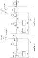
図11は、比較例に係る広帯域光源の構成図である。図11に示される広帯域光源は、ファイバーレーザ101と、光ファイバー増幅器102と、フォトニック結晶ファイバー103と、分散補償光学系104とを備える。ファイバーレーザ101と、光ファイバー増幅器102とは光ファイバーで接続される。光ファイバー増幅器102と分散補償光学系104とは光ファイバーで接続される。分散補償光学系104とフォトニック結晶ファイバー103とは光ファイバーで接続される。
FIG. 11 is a configuration diagram of a broadband light source according to a comparative example. The broadband light source shown in FIG. 11 includes a
ファイバーレーザ101は、共振器107と、光源109とを備え、共振器107は、Ybドープファイバー105と、可飽和吸収体106と、アウトプットカプラー108と、分散補償光学系110と、インプットカプラー111とを含む。インプットカプラー111は2入力1出力のカプラーであり、アウトプットカプラー108は1入力2出力のカプラーである。光源109はインプットカプラー111の第1の入力端に接続され、共振器107に約1μmの波長を有する光を供給する。インプットカプラー111の出力端はYbドープファイバー105の一端に接続される。Ybドープファイバー105の他端はアウトプットカプラー108の入力端に接続される。アウトプットカプラー108の第1の出力端は、ファイバーレーザ101の出力端を構成しており、光ファイバー増幅器102の入力端に接続される。アウトプットカプラー108の第2の出力端は、分散補償光学系110の入力端に接続される。分散補償光学系110の出力端は可飽和吸収体106の入力端に接続され、可飽和吸収体106の出力端はインプットカプラー111の第2の入力端に接続される。
The
Ybドープファイバー105は、ファイバーレーザ101の利得媒体である。可飽和吸収体106は、ピークパワーが高い光に対しては吸収損失が低くなり、ピークパワーが低い光に対しては吸収損失が高くなるように設計された光学部品である。分散補償光学系110の群遅延分散は、波長1μm近傍の光が共振器を一周したときに、群遅延分散の総和が負又はゼロ付近となるように設計されている。すなわち、分散補償光学系110を除く光学部品の群遅延分散の総和である群遅延分散D1は正の値であり、分散補償光学系110の群遅延分散は群遅延分散D1と絶対値がほぼ等しい負の値である。よって、パルス光が共振器107を周回する際、分散補償光学系110によってパルス幅の広がりが補償される。その結果、共振器107内を周回するパルス光は、狭いパルス幅を保った状態で可飽和吸収体106を通過することが可能となり、共振器107を伝搬するパルス光の可飽和吸収体106における損失が下がる。よって、共振器107を伝搬する光は狭いパルス幅を有するパルス光となる。このようにしてパルス光が安定して発振する状態をモード同期と呼び、モード同期した状態で生成されるパルス光をモード同期パルス光と呼ぶ。
The Yb-doped
ファイバーレーザ101より出力されるパルス光は、光ファイバー増幅器102に入力され増幅される。光ファイバー増幅器102は、Ybドープファイバー112と、2入力1出力のカプラー113と、光源114とを含む。Ybドープファイバー112は、光ファイバー増幅器102の利得媒体である。カプラー113の2つの入力端には、ファイバーレーザ101の出力端と、光源114の出力端とが接続される。カプラー113の出力端は、Ybドープファイバー112の一端に接続され、Ybドープファイバー112の他端は分散補償光学系104の入力端に接続される。この構成により、光ファイバー増幅器102で増幅されたパルス光は分散補償光学系104を介して、フォトニック結晶ファイバー103の一端に入力される。
The pulsed light output from the
フォトニック結晶ファイバー103の他端はSC光を射出する広帯域光源の出力端である。フォトニック結晶ファイバー103は、波長1μm近傍の光に対して、異常分散(すなわち、群速度分散が負の値である分散)となる。
The other end of the
光ファイバー増幅器102で増幅され、分散補償光学系104に到達したパルス光は、共振器107の出力端(すなわちアウトプットカプラー108の第1の出力端)と、分散補償光学系104の入力端との間の群遅延分散D2により、パルス幅が広がっている。分散補償光学系104は、この群遅延分散D2を補償するように設計されている。すなわち、分散補償光学系104の群遅延分散は、群遅延分散D2と絶対値がほぼ等しい負の値である。この群遅延分散D2の補償により、分散補償光学系104を通過したパルス光のパルス幅は狭くなる。このように、分散補償光学系104、110を用いた従来の広帯域光源では、光ファイバーなどの分散により生じるパルス幅の広がりを抑えることができる。その結果、500fs以下のパルス幅を有するとともに高いピーク強度を有するパルス光をフォトニック結晶ファイバーに入射させることができる。なお、分散補償光学系104、110としては、プリズム対、回折格子対、チャープ・ファイバー・ブラッグ・グレーティング(chirp fiber Bragg grating)、ホーリーコアファイバーなどが例示される。
The pulsed light that has been amplified by the
フォトニック結晶ファイバー103から射出されるSC光のスペクトルは、フォトニック結晶ファイバー103に入射されるパルス光のピーク強度が高いほど、広帯域となる。よって、分散補償光学系104、110を用いることで得られた高ピーク強度をもつパルス光をフォトニック結晶ファイバー103に入射させることにより、広帯域なスペクトルを有するSC光の発生が可能となる。
The spectrum of the SC light emitted from the
しかしながら、このような広帯域光源は、分散補償光学系104、110を備えることにより、光源の大型化、部品アライメントの煩雑さ、アライメントずれによる光源の不安定性といった課題が生じ得る。これに対し、以下の各実施形態では、分散補償光学系を用いずにSC光を発生可能とした、より好適な広帯域光源の構成例を説明する。
However, such a broadband light source may have problems such as an increase in size of the light source, complexity of component alignment, and instability of the light source due to misalignment due to the provision of the dispersion compensation
(第1の実施形態)
以下、第1の実施形態に係る広帯域光源を、図1乃至図3を参照して説明する。図1は、第1の実施形態に係る広帯域光源の構成図である。上述の比較例と重複する部分については説明を簡略化又は省略することもある。
(First embodiment)
The broadband light source according to the first embodiment will be described below with reference to FIGS. 1 to 3. FIG. 1 is a configuration diagram of a broadband light source according to the first embodiment. Descriptions of portions overlapping with the above-described comparative example may be simplified or omitted.
広帯域光源は、ファイバーレーザ101と、光ファイバー増幅器102と、フォトニック結晶ファイバー103とを備える。光ファイバー増幅器102と、フォトニック結晶ファイバー103との間に分散補償光学系104が設けられていない点が上述の比較例とは異なる。なお、各実施形態において説明されるフォトニック結晶ファイバーは例示でありこれに限定されない。フォトニック結晶ファイバーは非線形効果を発生させ得る任意の非線形ファイバーに置換可能である。
The broadband light source includes a
ファイバーレーザ101は、モード同期パルス光を生成する共振器107と、光源109とを備え、共振器107は、Ybドープファイバー105と、可飽和吸収体106と、アウトプットカプラー108と、インプットカプラー111とを含む。アウトプットカプラー108と、可飽和吸収体106との間に分散補償光学系110が設けられていない点が上述の比較例とは異なる。
The
光源109より出力される励起光は、インプットカプラー111を経由してYbドープファイバー105に入射され、Ybドープファイバー105内を伝搬する。このとき、励起光によりYbドープファイバー105は励起される。励起されたYbドープファイバー105は1000〜1100nmの間の波長を有する光を放出する。Ybドープファイバー105より放出された光の一部は共振器107内で共振する。共振器107に含まれる可飽和吸収体106は、パルス光に対して低い吸収率を有する。換言すると、可飽和吸収体106は、パルス光を選択的に透過させるため、共振器107内で共振する光はパルス光となる。このパルス光の中心波長λに対する共振器107の群遅延分散D1は正の値である。ここで、共振器107の群遅延分散D1とは、モード同期パルス光が共振器107を一周する間に感受する群遅延分散である。群遅延分散D1は、パルス光が共振器107を一周する間に透過する光学部品の群遅延分散の和と等しい。また、光ファイバーの群遅延分散は、光ファイバーの群速度分散に光ファイバーの長さを掛けたものに等しい。共振器107で共振するパルス光は、アウトプットカプラー108を経由してその一部がファイバーレーザ101の出力として共振器107の外部に取り出される。
Excitation light output from the
ファイバーレーザ101と、光ファイバー増幅器102と、フォトニック結晶ファイバー103とは、光学的に接続されている。ファイバーレーザ101から出力されるモード同期パルス光は、光ファイバー増幅器102でそのパワーが増幅されたのち、フォトニック結晶ファイバー103の入力端に入射される。フォトニック結晶ファイバー103は、入射されたモード同期パルス光が通過する際に、非線形効果によってSC光を発生させる。発生したSC光はフォトニック結晶ファイバー103の出力端から射出される。
The
共振器107の出力端(すなわち、アウトプットカプラー108の出力端)とフォトニック結晶ファイバー103の入力端との間の群遅延分散D2は正の値である。換言すると、群遅延分散D2は、ファイバーレーザ101より出力されたパルス光が、フォトニック結晶ファイバー103の入力端に到達するまでに感受する群遅延分散である。したがって、群遅延分散D2は、ファイバーレーザ101と光ファイバー増幅器102とを接続する光学部品、光ファイバー増幅器102、及び光ファイバー増幅器102とフォトニック結晶ファイバー103を接続する光学部品の群遅延分散の和である。これらの光学部品のいずれかが光ファイバーである場合、その群遅延分散は、光ファイバーの群速度分散に光ファイバーの長さを掛けた値に等しい。
The group delay dispersion D2 between the output end of the resonator 107 (that is, the output end of the output coupler 108) and the input end of the
ファイバーレーザ101から出力されて、フォトニック結晶ファイバー103の入力端に到達するパルス光は、群遅延分散D1、D2の影響を受け、そのパルス幅が広がる。スペクトル半値全幅Δλ(以下、スペクトル幅Δλ)を有するパルス光のフーリエ限界パルス半値全幅T0は、次式で得られる。
ここで、λはパルス光の中心波長であり、aはパルス光の形状に基づく係数である。また、cは真空中の光速である。なお、パルス光の係数aはパルス光の形状に応じて変化し得る。例えば、パルス光の形状がSech2型での場合、aの値は0.315である。パルス光の形状がガウシアン型の場合、aの値は0.441である。以降では、一例として、パルス光の形状はSech2型のパルスであるものとし、各式において、aに0.315を代入したものを用いて説明する。このパルス光が群遅延分散D1とD2を有する光学系を通過した後のパルス半値全幅(以下、パルス幅)Tは次式で表される。
図2は、式(3)においてD1+D2≠0のときのパルス幅Tをスペクトル幅Δλの関数T(Δλ)としてプロットしたグラフである。図2に示されるように、パルス幅Tを決定する関数T(Δλ)は、スペクトル幅Δλ=Δλ_minのときに極小値かつ最小値となる。図2によれば、ファイバーレーザ101から出力されるパルス光のスペクトル幅Δλを選択することで、フォトニック結晶ファイバー103に入射されるパルス光のパルス幅Tを所望の値とすることができる。一般的に、広帯域のSC光を発生させるためには、ファイバーレーザ101から出力されるパルス光のスペクトル幅Δλは、パルス幅Tが極小値となるスペクトル幅Δλ_minの近傍の値であることが望ましい。しかしながら、波長帯域幅の狭いSC光を発生させるために、スペクトル幅ΔλをΔλ_minから離れた値としてもよい。
FIG. 2 is a graph in which the pulse width T when D1+D2≠0 in the equation (3) is plotted as a function T(Δλ) of the spectral width Δλ. As shown in FIG. 2, the function T(Δλ) that determines the pulse width T has a minimum value and a minimum value when the spectrum width Δλ=Δλ_min. According to FIG. 2, by selecting the spectral width Δλ of the pulsed light output from the
ファイバーレーザ101において、共振器107の群遅延分散D1が正の値である場合パルス光が共振器107を一周する際のパルス幅Tの広がり率(=一周した後のパルス幅T1/一周する前のフーリエ限界パルス半値全幅T0)は以下の式で表される。
共振器107を一周したパルス光の電磁波は、分散による位相の変調を受ける。その位相回転角φdは、以下の式で表される。
ここでβ2は、共振器107を構成するファイバー及び光学部品の群速度分散の平均値である。β2は、共振器107の群遅延分散D1を共振器107の長さLで割った値にほぼ等しく、正の値である。
Here, β 2 is the average value of the group velocity dispersion of the fiber and the optical component that form the
図3は、(Δλ)2に対して位相回転角φdの絶対値をプロットしたグラフである。なお、横軸の(Δλ)2の値は、1/(D1(c/0.315λ2)2)で規格化されている。図3より、Δλが大きいほど位相回転角φdの絶対値は大きくなる。またパルス光は、共振器107を構成する光ファイバーの非線形光学効果である自己位相変調(self-phase-modulation、以下SPMと呼ぶ)による位相の変調を受ける。この効果により、群遅延分散D1が正の値をもつ共振器107では、位相回転角φdを有するパルス光がモード同期する。このように、自己位相変調による位相変調の効果を受けてモード同期したパルス光は、シミラリトンパルス(similariton pulse)と呼ばれる。自己位相変調の強さ(すなわち、自己位相変調による位相回転角φSPM)は、以下の式で表される。
![]()
![]()
ここで、γは共振器107を構成する光ファイバーの非線形係数の平均値であり、Ppeakは共振器107を伝搬するパルス光のピークパワーの平均値である。分散による位相回転角φdが大きい場合、それを補償する自己位相変調による位相回転角φSPMも大きくなければならない。式(6)で表されるように、パルス光のピーク強度を高くすることで、自己位相変調による位相回転角φSPMを大きくすることができる。しかしながら、共振器107内を伝搬するパルス光のパワーを大きくしすぎると、発熱によりファイバーレーザ101の不安定化が生じることがある。また、共振器107内部の部品、特に可飽和吸収体106の破損が生じることもある。一方、分散による位相回転角φdが小さい場合、自己位相変調による位相回転角φSPMが小さくても分散による位相の変調を補償することができる。すなわち、スペクトル幅Δλが小さい場合、分散による位相回転角φdが小さくなるので、パルス光のパワーを小さくしたとしてもシミラリトンパルスを生成し得る。これにより、ファイバーレーザ101のモード同期が安定化し、かつ共振器107内部の部品の破損が生じにくくなり得る。
Here, γ is the average value of the nonlinear coefficients of the optical fibers forming the
ここで、パルス光のスペクトル幅Δλは、誘電体多層膜、ファイバー・ブラッグ・グレーティングなどの多重干渉を利用した、所望のスペクトルバンド幅を有する光学フィルターを共振器107内に設けることによって制御され得る。
Here, the spectral width Δλ of the pulsed light can be controlled by providing an optical filter having a desired spectral bandwidth utilizing multiple interference such as a dielectric multilayer film and a fiber Bragg grating in the
パルス幅Tが極小値を取るときの自己位相変調による位相回転角φSPMの大きさは、スペクトル幅Δλ_minの2倍のときに群遅延によって生じる位相回転角とほぼ等しいか、やや大きいことが実験により得られている。スペクトル幅がΔλ_minよりも大きくなると、パルス幅Tが大きくなり、ピークパワーが小さくなるが、スペクトル幅Δλ_minの2倍以下であれば、同じパルスエネルギーであっても自己位相変調により位相回転角が補償される。したがって、スペクトル幅Δλは、パルス幅Tが極小値となるスペクトル幅Δλ_minの2倍以下とすることが好ましい。これにより、ファイバーレーザ101におけるモード同期を安定化し、かつ共振器107内部の部品の破損を生じにくくするために十分な程度にパルス光のパワーを小さくすることができる。また、スペクトル幅Δλをスペクトル幅Δλ_minの2倍以下とすることにより、スペクトル幅ΔλをSC光の広帯域化に有効なΔλ_min近傍とすることができる。
Experiments show that the magnitude of the phase rotation angle φ SPM due to self-phase modulation when the pulse width T takes a minimum value is almost equal to or slightly larger than the phase rotation angle caused by the group delay when the spectrum width Δλ_min is twice. Has been obtained by. When the spectral width becomes larger than Δλ_min, the pulse width T becomes large and the peak power becomes small. However, if the spectral width is twice the spectral width Δλ_min or less, the phase rotation angle is compensated by self-phase modulation even with the same pulse energy. To be done. Therefore, it is preferable that the spectral width Δλ is equal to or less than twice the spectral width Δλ_min at which the pulse width T has the minimum value. This makes it possible to reduce the power of the pulsed light sufficiently to stabilize the mode-locking in the
また、スペクトル幅Δλは、パルス幅Tが極小値となるスペクトル幅Δλ_min以下とすることがより好ましい。パルス光のパワーをより小さくすることができ、ファイバーレーザ101におけるモード同期の安定化と共振器107内部の部品の破損の発生低減をより確実なものとすることができる。また、上述と同様に、スペクトル幅ΔλをSC光の広帯域化に有効なΔλ_min近傍とすることができる。
Further, the spectral width Δλ is more preferably equal to or smaller than the spectral width Δλ_min at which the pulse width T has a minimum value. The power of the pulsed light can be made smaller, and the mode locking in the
また、図2で示されるように、スペクトル幅ΔλがΔλ_min以下の領域では、パルス幅Tはスペクトル幅Δλの変化に対して急激に変化する。上述のように、パルス光のスペクトル幅Δλは、誘電体多層膜、ファイバー・ブラッグ・グレーティングなどの多重干渉を利用した、所定のスペクトルバンド幅を有する光学フィルターを共振器107内に設けることによって制御される。これらの光学フィルターのスペクトルバンド幅の精度(バラつき)は約0.01%である。例えば波長が1000nmのパルス光であれば、約0.1nmである。光学フィルターのスペクトルバンド幅のバラつきによって生じるパルス幅Tのバラつきは、フォトニック結晶ファイバー103に入射するパルス光のピークパワーPin peakのバラつきを生じさせる。パルス光のピークパワーは、パルス光のパルス幅Tに反比例することから、このピークパワーのバラつきδPin peak/Pin peakは、パルス光のパルス幅TのバラつきδT/Tとほぼ同程度である。このようなピークパワーのバラつきδPin peak/Pin peakは、光ファイバー増幅器102の増幅率を調整することにより補償することができる。
Further, as shown in FIG. 2, in the region where the spectral width Δλ is equal to or less than Δλ_min, the pulse width T changes rapidly with respect to the change of the spectral width Δλ. As described above, the spectral width Δλ of the pulsed light is controlled by providing an optical filter having a predetermined spectral bandwidth, which utilizes multiple interference such as a dielectric multilayer film and a fiber Bragg grating, in the
しかしながら、光ファイバー増幅器102の増幅率の調整可能範囲には限界がある。この調整可能範囲を考慮して、ピークパワーのバラつきδPin peak/Pin peakは、ファイバーレーザ101とフォトニック結晶ファイバー103との間に設けられるアイソレータ等の光学部品の透過損失と同程度、又はそれ未満とすることが望ましい。このような観点から、パルス幅TのバラつきδT/Tは、ファイバーカップル型の光学部品で通常許容される透過損失3dB(約50%)以下であることが望ましい。
However, the adjustable range of the amplification factor of the
よって、ファイバーレーザ101より出力されるパルス光のスペクトル幅Δλは、Δλを中心波長に対して約0.01%変化させたときのパルス幅TのバラつきδT/Tが3dB(約50%)となるスペクトル幅Δλ_3dB以上とすることが望ましい。換言すると、スペクトル幅Δλは、Δλを中心波長に対して約0.01%増加させたときのパルス幅Tの変化量が−3dBとなるスペクトル幅Δλ_3dB以上とすることが望ましい。
Therefore, the spectral width Δλ of the pulsed light output from the
図2には、Δλを中心波長に対して約0.01%増加させたときのパルス幅Tの変動量が−3dBであるスペクトル幅Δλ_3dBが図示されている。Δλ_3dBにおけるパルス幅TをT_3dB、Δλ_3dBにおける接線の傾きをdT/dΔλ[ps/nm]とすると、以下の式が成り立つ。
![]()
![]()
以上の説明を整理すると、ファイバーレーザ101より出力されるパルス光のスペクトル幅Δλは、Δλ_3dB≦Δλ≦Δλ_min×2の関係を満たすことが好ましい。この場合、ファイバーレーザ101におけるモード同期の安定化及び共振器107内部の部品の破損低減が実現されるとともに、ピークパワーのバラつきを光ファイバー増幅器102の調整可能範囲内とすることができる。また、Δλ_3dB≦Δλ≦Δλ_minの関係を満たすことがより好ましい。パルス光のパワーをより小さくすることができ、ファイバーレーザ101におけるモード同期の安定化と共振器107内部の部品の破損低減をより確実なものとすることができる。
To summarize the above description, it is preferable that the spectral width Δλ of the pulsed light output from the
以上のように、本実施形態によれば、分散補償光学系を用いることなくSC光を発生し得る光源装置が提供される。そのため、分散補償光学系を備えることにより生じうる、光源の大型化、部品アライメントの煩雑さ、アライメントずれによる光源の不安定性といった問題が軽減され得る。 As described above, according to this embodiment, a light source device that can generate SC light without using a dispersion compensation optical system is provided. Therefore, problems such as an increase in size of the light source, complexity of component alignment, and instability of the light source due to misalignment that may occur due to the provision of the dispersion compensation optical system can be alleviated.
以上、本発明の基本構成について第1の実施形態として説明した。第1の実施形態の構成をより明確にし、あるいは構成の一部を変形した例を、以下、第2の実施形態及び第3の実施形態として説明する。第2の実施形態及び第3の実施形態の説明においても、上述の比較例、第1の実施形態と重複する部分については説明を簡略化又は省略することがある。 The basic configuration of the present invention has been described above as the first embodiment. An example in which the configuration of the first embodiment is made clearer or a part of the configuration is modified will be described below as a second embodiment and a third embodiment. Also in the description of the second embodiment and the third embodiment, the description of the parts overlapping the comparative example and the first embodiment may be simplified or omitted.
(第2の実施形態)
図4は、第2の実施形態に係る広帯域光源の構成図である。ファイバーレーザ101は、共振器107と光源109とを含む。共振器107は、可飽和吸収体106と、アウトプットカプラー108と、バンドパスフィルター115と、インプットカプラー111と、Ybドープファイバー105とを含む。バンドパスフィルター115は、アウトプットカプラー108と可飽和吸収体106の間に設けられる光学フィルターである。可飽和吸収体106は、例えば、半導体、カーボンナノチューブ、グラフェンのうちの1又は複数を材料として含んでおり、共振器内を伝搬する光に対して、透過型可飽和吸収体として機能する。すなわち、可飽和吸収体106は、共振器107内を伝搬するパルス光を低損失で透過させ、パルス光でない光には高い損失を与える。インプットカプラー111は、例えば、波長分割多重カプラーである。
(Second embodiment)
FIG. 4 is a configuration diagram of a broadband light source according to the second embodiment. The
Ybドープファイバー105は、例えば、シングルモードファイバーであり、Coractive社製の型番Yb406を使用することができる。共振器107内を伝搬するパルス光は、Ybドープファイバーの発光波長帯である1000nmから1100nmのいずれかの波長の光を含んでいる。アウトプットカプラー108は、共振器107を伝搬してアウトプットカプラー108に到達したパルス光のパワーのうちの50%を出力として共振器107の外部に取り出し、残りの50%のパワーを共振器107の内部に戻す。
The Yb-doped
バンドパスフィルター115の透過スペクトルの中心波長と共振器107内を伝搬するパルス光の中心波長λとはほぼ一致する。所望のスペクトルバンド幅を有するバンドパスフィルター115を用いることにより、パルス光のスペクトル幅Δλを所望の値に制御することができる。バンドパスフィルター115として、例えば、誘電体多層膜により構成されるバンドパスフィルターを用いることができる。バンドパスフィルター115の中心波長は、例えば、1030nmとすることができる。バンドパスフィルター115の透過スペクトルのバンド幅は、例えば、2.5nmとすることができる。この場合、パルス光のスペクトル幅Δλは、約2.5nmとなる。
The center wavelength of the transmission spectrum of the
光源109は、例えば、レーザダイオードである。光源109は、Ybドープファイバー105の吸収波長と一致する波長の励起光を出力する。光源109から出力される励起光の波長は、例えば、980nmとすることができる。励起光は、インプットカプラー111を通って、共振器107に入射される。共振器107に入射された励起光は、Ybドープファイバー105を励起する。励起されたYbドープファイバー105は、誘導放出過程によって共振器107内を伝搬するパルス光にエネルギーを与える。共振器107を構成するこれらの光学部品は、パルス光の波長λに対してシングルモードとなるシングルモードファイバーにより接続される。このシングルモードファイバーには、例えばコーニング社製、型番HI1060を用いることができる。
The
パルス光が共振器107を一周する際の伝搬距離、すなわち共振器107の長さは6mである。上述の構成におけるファイバーレーザ101は、中心波長λ=1030nm、スペクトル幅Δλ=2.5nm、繰り返し周波数f=30MHz、出力パワー約5mWのパルス光を出力する。ファイバーレーザ101から出力されるパルス光はモード同期されており、その繰り返し周波数fは、パルス光が共振器107を一周する時間の逆数にほぼ反比例する。共振器107の群遅延分散は、共振器107に含まれる光学部品及び光ファイバーの群遅延分散の和となる。共振器107に含まれるバンドパスフィルター115、可飽和吸収体106、アウトプットカプラー108及びインプットカプラー111の群遅延分散は、Ybドープファイバー105及び光学部品間を接続する光ファイバーの群遅延分散に比べると十分に小さい。そのため、共振器107の群遅延分散D1は、実質的に光ファイバーの群遅延分散により決定される。共振器107に含まれる光ファイバーの群速度分散の平均値は0.025(ps2/m)である。これに共振器107の長さ6mを掛けて得られる群遅延分散D1は、0.15(ps2)である。
The propagation distance when the pulsed light goes around the
光ファイバー増幅器102は、Ybドープファイバー112と、カプラー113と、光源114とを備えている。Ybドープファイバー112は、例えば、ダブルクラッドファイバーであり、その長さは3mである。Ybドープファイバー112としては、例えば、Coractive社製の型番DCF−Yb−10/128−Eを用いることができる。
The
光源114は、例えばレーザダイオードであり、Ybドープファイバー112の吸収波長である980nmの励起光を出力する。カプラー113は波長分割多重カプラーであり、カプラー113の2つの入力端にはそれぞれ、光源114の出力端であるファイバーと、ファイバーレーザ101から出力されたパルス光を伝搬するファイバーとが接続される。カプラー113の出力端にはYbドープファイバー112が接続されており、励起光は、カプラー113を介してYbドープファイバー112へと伝搬され、Ybドープファイバー112を励起する。
The
フォトニック結晶ファイバー103は、パルス光の中心波長λ(=1030nm)において異常分散を有している。フォトニック結晶ファイバー103としては、例えば、ゼロ分散波長が975nmであるNKTフォトニクス社製の型番SC−3.7−975を用いることができる。フォトニック結晶ファイバー103の長さは、例えば、1mから3mの範囲で選択することができる。
The
ファイバーレーザ101と、光ファイバー増幅器102は、アイソレータ116を介して光ファイバーで接続されている。光ファイバー増幅器102と、フォトニック結晶ファイバー103とは、アイソレータ117を介して光ファイバーで接続されている。ファイバーレーザ101より出力されたパルス光は、光ファイバー増幅器102で増幅されて、フォトニック結晶ファイバー103の入力端に到達する。フォトニック結晶ファイバー103に到達したパルス光は約1Wのパワーに増幅されている。共振器107の出力端(すなわち、アウトプットカプラー108の出力端)からフォトニック結晶ファイバー103の入力端までのファイバーの長さは、例えば、約4mである。
The
ファイバーレーザ101の出力端からフォトニック結晶ファイバー103の入力端までの群遅延分散D2は、それらを結ぶ光学部品と光ファイバーの群遅延分散の和となる。光学部品であるアイソレータ116、117、カプラー113の群遅延分散は、Ybドープファイバー112及び光学部品間を接続する光ファイバーの群遅延分散に比べると十分に小さい。そのため、群遅延分散D2は、実質的に光ファイバーの群遅延分散により決定される。共振器107の出力端(すなわち、アウトプットカプラー108の出力端)からフォトニック結晶ファイバー103の入力端までの光ファイバーの群速度分散の平均値は約0.025(ps2/m)である。これにファイバーの長さ約4mを掛けて得られる群遅延分散D2は、約0.10(ps2)である。
The group delay dispersion D2 from the output end of the
図5は、パルス幅Tとスペクトル幅Δλとの関係を表すグラフである。パルス幅Tはスペクトル幅2.2nm(=Δλ_min)で極小値かつ最小値となる。したがって、スペクトル幅Δλを4.4nm以下とすれば、パルス幅Tが最小となるΔλ_minの近傍のスペクトル幅を含み、かつ分散による位相回転角φdを小さくすることができる。φdが小さいファイバーレーザ101は、パワーの小さいパルス光でもモード同期させることが可能である。したがって、共振器107のモード同期が安定し、かつ部品の破損が生じにくい広帯域光源が実現される。なお、図中の破線Aは、スペクトル幅を0.1nm変化させたときに、パルス幅Tの変化量が3dBとなるスペクトル幅Δλ_3dBを表している。図中の破線Bは、パルス幅Tが最小となるスペクトル幅Δλ_minを表している。図中の破線Cは、スペクトル幅Δλ_min×2を表している。
FIG. 5 is a graph showing the relationship between the pulse width T and the spectral width Δλ. The pulse width T has a minimum value and a minimum value when the spectrum width is 2.2 nm (=Δλ_min). Therefore, if the spectral width Δλ is set to 4.4 nm or less, it is possible to reduce the phase rotation angle φ d due to dispersion, including the spectral width near Δλ_min where the pulse width T becomes the minimum. The
図6は、図5のグラフにおいてスペクトル幅Δλ_3dBの近傍を拡大したものである。スペクトル幅Δλ_3dBは、0.2nmである。スペクトル幅Δλ_3dBにおけるパルス幅T_3dBは、5psである。スペクトル幅Δλ_3dB、パルス幅T_3dBを接点とする接線の傾き(dT/dΔλ)は、約25(ps/nm)である。また、スペクトル幅がδΔλ=0.1nm増加させたときのパルス幅の変化量は、(dT/dΔλ)×δΔλ/T_3dB=−25(ps/nm)×0.1nm/5ps=−0.5である。すなわち、Δλ_3dBにおいてスペクトル幅を0.1nm増加させたときのパルス幅Tの変化量は、−3dBとなっている。したがって、ファイバーレーザ101より出力されるパルス光のスペクトル幅Δλが0.2nm以上であれば、パルス幅Tの変化量の絶対値は、3dB以下となる。このとき、バンドパスフィルター115のスペクトルバンド幅のバラつきにより生じるパルス幅のバラつき、すなわちピークパワーのバラつきは、アイソレータ116、117などの光学部品の透過損失とほぼ同程度となる。したがって、このピークパワーのバラつきは、光ファイバー増幅器102による増幅率の調整によって補正が可能な範囲内となる。
FIG. 6 is an enlarged view of the vicinity of the spectral width Δλ_3 dB in the graph of FIG. The spectral width Δλ_3 dB is 0.2 nm. The pulse width T_3 dB in the spectral width Δλ_3 dB is 5 ps. The slope (dT/dΔλ) of the tangent line with the spectral width Δλ_3 dB and the pulse width T_3 dB as the contact point is about 25 (ps/nm). The amount of change in pulse width when the spectral width is increased by δΔλ=0.1 nm is (dT/dΔλ)×δΔλ/T_3 dB=−25 (ps/nm)×0.1 nm/5ps=−0.5. Is. That is, the change amount of the pulse width T when the spectrum width is increased by 0.1 nm in Δλ_3 dB is −3 dB. Therefore, if the spectral width Δλ of the pulsed light output from the
第2の実施形態において、ファイバーレーザ101より出力されるパルス光のスペクトル幅Δλは、約2.5nmである。すなわち、スペクトル幅Δλは、パルス幅Tを最小にするスペクトル幅Δλ_minの2倍よりも狭く、スペクトル幅Δλが0.1nm増加したときのパルス幅Tの変化量が−3dBとなるスペクトル幅Δλ_3dBよりも広い。言い換えると、Δλ_3dB≦Δλ≦Δλ_min×2の関係を満たしている。
In the second embodiment, the spectral width Δλ of the pulsed light output from the
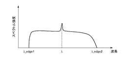
その結果、第2の実施形態の広帯域光源は、ファイバーレーザ101のモード同期が安定しており、光学部品の破損が生じにくい。さらに、第2の実施形態の広帯域光源は、スペクトル幅Δλのバラつきに起因するパルス幅Tのピーク強度のバラつきを光ファイバー増幅器102により補正可能な範囲とすることができる。また、第2の実施形態において、フォトニック結晶ファイバー103に入射されるパルス光のパルス幅は十分に短い。そのため、フォトニック結晶ファイバー103から射出されるSC光は十分に広帯域化されている。図7は、第2の実施形態に係る広帯域光源より出力されるSC光のスペクトル強度分布を表すグラフである。図7において、λ_edge1=500nm、λ_edge2>1600nmであり、500nm以上700nm以下の波長帯におけるスペクトル強度は0.2mW/nm以上である。そのため、本実施形態に係る光源装置は、可視光領域の光源として良好な特性を有している。
As a result, in the broadband light source of the second embodiment, the mode-locking of the
以上のように、本実施形態によれば、分散補償光学系を用いることなくSC光を発生し得る光源装置が提供される。そのため、分散補償光学系を備えることにより生じうる、光源の大型化、部品アライメントの煩雑さ、アライメントずれによる光源の不安定性といった問題が軽減され得る。 As described above, according to this embodiment, a light source device that can generate SC light without using a dispersion compensation optical system is provided. Therefore, problems such as an increase in size of the light source, complexity of component alignment, and instability of the light source due to misalignment that may occur due to the provision of the dispersion compensation optical system can be alleviated.
なお、本実施形態では、共振器107に含まれるすべての光ファイバー及び光学部品は、正の群遅延分散を有している。このような構成では群遅延分散D1が大きくなりやすいので、上述の本実施形態の効果がより有効なものとなる。また、本実施形態では、共振器107の出力端からフォトニック結晶ファイバー103の入力端の間の光路に含まれるすべての光ファイバー及び光学部品も、正の群遅延分散を有している。このような構成では群遅延分散D2が大きくなりやすいので、上述の本実施形態の効果がより有効なものとなる。
In this embodiment, all optical fibers and optical components included in the
(第3の実施形態)
図8は、第3の実施形態に係る広帯域光源の構成図である。ファイバーレーザ101は共振器207と光源109とを含む。共振器207は、可飽和吸収ミラー206と、ファイバー・ブラッグ・グレーティングミラー(FBGミラー)208と、インプットカプラー111と、Ybドープファイバー105とを含む。可飽和吸収ミラー206とFBGミラー208とで挟まれた領域はファイバーレーザ101の共振器207を構成する。可飽和吸収ミラー206は、例えば、半導体、カーボンナノチューブ、グラフェンのうちの1又は複数を材料として含んでおり、反射する光に対して、可飽和吸収体として機能する。すなわち、可飽和吸収ミラー206は、共振器207内を伝搬するパルス光を低損失で反射し、パルス光でない光が反射する際に高い損失を与える。
(Third Embodiment)
FIG. 8 is a configuration diagram of a broadband light source according to the third embodiment. The
共振器207内を伝搬するパルス光は、波長帯1000nmから1100nmのいずれかの波長の光を含んでいる。FBGミラー208はアウトプットカプラーの機能と光学フィルターの機能とを備えている。FBGミラー208は、共振器207を伝搬してFBGに到達したパルス光のパワーの50%を出力として共振器の外部に取り出し、残りの50%のパワーを共振器207の内部に戻す。FBGミラー208の反射スペクトルの中心波長と共振器207内を伝搬するパルス光の中心波長λとはほぼ一致している。FBGミラー208により反射された光が共振器207内で共振し、パルス光となる。したがって、所望の反射スペクトルのバンド幅を有するFBGミラー208を用いることにより、パルス光のスペクトル幅Δλを所望の値に制御することができる。FBGミラー208として、例えば、誘電体多層膜、半導体多層膜等を用いることができる。FBGミラー208の反射スペクトルの中心波長は、例えば、1030nmとする。FBGミラー208の反射スペクトルのバンド幅は、例えば、1.0nmとする。このとき、共振器207内で共振するパルス光の中心波長は約1030nmとなり、スペクトル幅は約1.0nmとなる。
The pulsed light propagating in the
光源109は、例えば、レーザダイオードである。光源109は、Ybドープファイバー105の吸収波長と一致する波長の励起光を出力する。光源109から出力される励起光の波長は、たとえば980nmとすることができる。励起光は、インプットカプラー111を通って、共振器207に入射される。共振器207に入射された励起光は、Ybドープファイバー105を励起する。励起されたYbドープファイバーは、誘導放出過程によって共振器207内を伝搬するパルス光に光エネルギーを与える。共振器207を構成するこれら光学部品は、パルス光の波長λに対してシングルモードとなるシングルモードファイバーにより接続される。このシングルモードファイバーには、例えばコーニング社製、型番HI1060を用いることができる。
The
FBGミラー208と可飽和吸収ミラー206とを結ぶシングルモードファイバーとYbドープファイバー105の長さの合計は、約3mである。よって、パルス光が共振器207を一周する際の伝搬距離、すなわち共振器207の一往復分の長さは約6mである。上述の構成におけるファイバーレーザ101は、中心波長λ=1030nm、スペクトル幅Δλ=1.0nm、繰り返し周波数f=30MHz、出力パワー約3mWのパルス光を出力する。ファイバーレーザ101から出力されるパルス光はモード同期されており、その繰り返し周波数fは、パルス光が共振器207を一周する時間の逆数にほぼ反比例する。共振器207の群遅延分散は、共振器207に含まれる光学部品及び光ファイバーの群遅延分散の和となる。共振器207に含まれる可飽和吸収ミラー206、インプットカプラー111の群遅延分散は、Ybドープファイバー105及び光学部品間を接続する光ファイバーの群遅延分散に比べると十分に小さい。したがって、FBGミラー208の群遅延分散が無視できるほど小さい場合、共振器207の群遅延分散D1は、実質的に光ファイバーの群遅延分散により決定される。共振器207を構成する光ファイバーの群速度分散の平均値は0.025(ps2/m)である。これに共振器207の長さ6mを掛けて得られる群遅延分散D1は、0.15(ps2)である。
The total length of the single mode fiber connecting the
また、共振器207を構成するFBGミラー208の群遅延分散は負の値を有していてもよい。例えば、FBGミラー208の群遅延分散は、−0.05(fs2)の程度の値であってもよい。このとき、共振器207の群遅延分散D1は0.10(ps2)となる。さらに、共振器207を構成するFBGミラー208の群遅延分散は正の値を有していてもよい。例えば、FBGミラー208の群遅延分散は、+0.05fs2の程度の値であってもよい。このとき、共振器207の群遅延分散D1は0.20(ps2)となる。
Further, the group delay dispersion of the
光ファイバー増幅器102は、2段の増幅器を有する。光ファイバー増幅器102は、2本のYbドープファイバー211、214と、2個のカプラー212、215と、2個の光源213、216とを備えている。Ybドープファイバー211、カプラー212及び光源213は第1段目の増幅器を構成しており、Ybドープファイバー214、カプラー215及び光源216は第2段目の増幅器を構成している。なお、本実施形態では例示として2段の増幅器を有する構成としているが第2の実施形態と同様の1段であってもよく、2段以上、すなわち複数段であってもよい。増幅器の段数が複数段の場合、群遅延分散D2が大きくなりやすいので、本実施形態の効果がより有効なものとなる。
The
Ybドープファイバー211は、1mの長さを有するシングルモードファイバーであり、Ybドープファイバー214は、3mの長さを有するダブルクラッドファイバーである。光源213、216はYbドープファイバー211、214の吸収波長である980nmの励起光を出力する。カプラー212、215は波長分割多重カプラーである。カプラー212の2つの入力端にはそれぞれ、光源213の出力端であるファイバーと、ファイバーレーザ101から出力されたパルス光を伝搬するファイバーとが接続される。カプラー215の2つの入力端にはそれぞれ、光源216の出力端であるファイバーと、Ybドープファイバー211とが接続される。励起光は、カプラー212、215を介してYbドープファイバー211、214へとそれぞれ伝搬され、これらを励起する。
The Yb-doped
フォトニック結晶ファイバー103は、パルス光の中心波長λにおいて異常分散を有している。λが1030nmの場合、例えば、フォトニック結晶ファイバー103として、ゼロ分散波長が975nmであるNKTフォトニクス社製のSC−3.7−975を用いることができる。フォトニック結晶ファイバー103の長さは、例えば、1mから3mの範囲で選択することができる。
The
ファイバーレーザ101と、光ファイバー増幅器102は、アイソレータ116を介して光ファイバーで接続されている。光ファイバー増幅器102と、フォトニック結晶ファイバー103とは、アイソレータ117を介して光ファイバーで接続されている。ファイバーレーザ101より出力されたパルス光は、光ファイバー増幅器102で増幅されて、フォトニック結晶ファイバー103の入力端に到達する。フォトニック結晶ファイバー103に到達したパルス光は約3Wに増幅されている。共振器207の出力端(すなわち、FBGミラー208の出力端)からフォトニック結晶ファイバー103の入力端までのファイバーの長さは、約7mである。ファイバーレーザ101の出力端からフォトニック結晶ファイバー103の入力端までの群遅延分散D2は、それらを結ぶ光学部品と光ファイバーの群遅延分散の和となる。光学部品であるアイソレータ116、117、カプラー212、215の群遅延分散は、Ybドープファイバー211,214及び光学部品間を接続する光ファイバーの群遅延分散に比べると非常に小さい。そのため、群遅延分散D2は、実質的に光ファイバーの群遅延分散により決定される。ファイバーレーザ101の出力端からフォトニック結晶ファイバー103の入力端までの光ファイバーの群速度分散の平均値は0.025(ps2/m)であり、これにファイバーの長さ約7mを掛けて得られる群遅延分散D2は、約0.175(ps2)である。
The
図9は、パルス幅Tとスペクトル幅Δλとの関係を表すグラフである。パルス幅Tはスペクトル幅1.9nm(=Δλ_min)で極小値かつ最小値となる。したがって、スペクトル幅Δλを3.8nm以下とすれば、パルス幅Tが最小となるΔλ_minの近傍のスペクトル幅を含み、かつ分散による位相回転角φdを小さくすることができる。φdが小さいファイバーレーザ101は、パワーの小さいパルス光でもモード同期させることが可能である。したがって、モード同期が安定し、かつ部品の破損が起きにくい広帯域光源が実現される。なお、図中の破線Aは、スペクトル幅を0.1nm増加させたときに、パルス幅Tの変化量が−3dBとなるスペクトル幅Δλ_3dBを表している。
FIG. 9 is a graph showing the relationship between the pulse width T and the spectral width Δλ. The pulse width T has a minimum value and a minimum value when the spectrum width is 1.9 nm (=Δλ_min). Therefore, if the spectral width Δλ is set to 3.8 nm or less, the spectral width in the vicinity of Δλ_min where the pulse width T becomes the minimum is included, and the phase rotation angle φ d due to dispersion can be reduced. The
スペクトル幅Δλ_3dBは、0.2nmである。スペクトル幅Δλ_3dBにおけるパルス幅T_3dBは、5psである。スペクトル幅Δλ_3dB、パルス幅T_3dBを接点とする接線の傾き(dT/dΔλ)は、約−25(ps/nm)である。スペクトル幅がδΔλ=0.1nm変化したときのパルス幅の変化量は、(dT/dΔλ)×δΔλ/T_3dB=−25(ps/nm)×0.1nm/5ps=−0.5である。すなわち、Δλ_3dBにおいてスペクトル幅を0.1nm増加させたときのパルス幅Tの変化量は、−3dBとなっている。したがって、ファイバーレーザ101より出力されるパルス光のスペクトル幅Δλが0.2nm以上であれば、パルス幅Tの変化量の絶対値は、3dB以下となる。このとき、FBGミラー208のスペクトルバンド幅のバラつきにより生じるパルス幅のバラつき、すなわちピークパワーのバラつきは、アイソレータ116、117などの他の光学部品の透過損失とほぼ同程度となる。したがって、このピークパワーのバラつきは、FBGミラーのバンド幅のバラつきは光ファイバー増幅器102による増幅率の調整によって補正が可能な範囲内となる。
The spectral width Δλ_3 dB is 0.2 nm. The pulse width T_3 dB in the spectral width Δλ_3 dB is 5 ps. The slope (dT/dΔλ) of the tangent line with the spectral width Δλ_3 dB and the pulse width T_3 dB as a contact point is about −25 (ps/nm). The amount of change in pulse width when the spectral width changes by δΔλ=0.1 nm is (dT/dΔλ)×δΔλ/T_3 dB=−25 (ps/nm)×0.1 nm/5ps=−0.5. That is, the change amount of the pulse width T when the spectrum width is increased by 0.1 nm in Δλ_3 dB is −3 dB. Therefore, if the spectral width Δλ of the pulsed light output from the
ファイバーレーザ101より出力されるパルス光の出力パワーPoutは3mWであり、繰り返し周波数fは30MHzであり、中心波長λは1030nmである。このとき共振器207内のパルス光のピーク強度の平均値Ppeakは、おおよそ次式で見積もられる。
また、自己位相変調によるパルス光の位相回転角φSPMは次式で表される。
ここで、κは共振器207からのパルス光の取り出し効率、γは共振器207の非線形係数の平均値である。共振器207からのパルス光の取り出し効率はFBGミラー208の透過率とほぼ等しく、κの値は約0.5(50%)である。共振器207の非線形係数γの平均値は、約2.0(W−1/km)である。
Here, κ is the extraction efficiency of the pulsed light from the
図10は、自己位相変調によるパルス光の位相回転角φSPMをφSPM=0、0.5π、π、1.5π、2.5π、3.5π(rad)と変化させたときのパルス光のスペクトルの歪みの変化を表している。なお、πは円周率である。位相回転角φSPMが大きいほど、スペクトルの歪みは大きくなる。式(9)に示されるとおり、位相回転角φSPMはスペクトル幅Δλに比例することから、スペクトル幅Δλが大きいほどスペクトルの歪みは大きくなる。位相回転角φSPMが大きくスペクトルの歪みが大きい場合、共振器207内を伝搬するパルス光は不安定となりやすい。特に、図10に示されるように、位相回転角φSPMがπを超えるとスペクトルの歪みが顕著となる。よって、自己位相変調による位相回転角φSPMは、スペクトルの歪みが大きくなるπ(rad)(≒3.14(rad))よりも小さいことが望ましい。
FIG. 10 shows pulsed light when the phase rotation angle φ SPM of pulsed light by self-phase modulation is changed to φ SPM =0, 0.5π, π, 1.5π, 2.5π, 3.5π (rad). Represents the change in the distortion of the spectrum. Note that π is the circular constant. The larger the phase rotation angle φ SPM , the larger the distortion of the spectrum. As shown in the equation (9), the phase rotation angle φ SPM is proportional to the spectral width Δλ, and thus the larger the spectral width Δλ, the larger the distortion of the spectrum. When the phase rotation angle φ SPM is large and the distortion of the spectrum is large, the pulsed light propagating in the
ファイバーレーザ101より出力されるパルス光のスペクトル幅Δλは、FBGミラー208のバンド幅とほぼ同等の1nmである。このとき、自己位相変調による位相回転角φSPMは1.9(rad)であり、π(rad)よりも小さい。
The spectral width Δλ of the pulsed light output from the
ファイバーレーザより出力されるパルス光のスペクトル幅Δλは、FBGミラー208のバンド幅とほぼ同等の1nmである。すなわち、Δλは、パルス幅Tを最小にするスペクトル幅Δλ_minよりも狭い。したがって、第3の実施形態においては、第2の実施形態の構成よりもファイバーレーザ101のモード同期が安定し、かつ部品の破損も生じにくい。また、スペクトル幅Δλは、スペクトル幅Δλが0.1nm変化したときのパルス幅Tの変化量が3dBとなるスペクトル幅Δλ_3dB(=0.2nm)よりも広い。その結果、第3の実施形態の広帯域光源は、上述の効果に加え、スペクトル幅Δλのバラつきに起因するパルス光のピーク強度のバラつきを光ファイバー増幅器102により補正可能な範囲とすることができる。
The spectral width Δλ of the pulsed light output from the fiber laser is 1 nm, which is almost equal to the band width of the
さらに、第3の実施形態における自己位相変調による位相回転角φSPM(=1.9(rad))は、スペクトルの歪みが顕著となるπ(rad)(≒3.14(rad))よりも小さい。よって、共振器207内を伝搬するパルス光の安定性がより向上する。
Further, the phase rotation angle φ SPM (=1.9 (rad)) due to the self-phase modulation in the third embodiment is more than π (rad) (≈3.14 (rad)) where the distortion of the spectrum becomes remarkable. small. Therefore, the stability of the pulsed light propagating in the
出力パワーPout=3mW、繰り返し周波数f=30MHz、中心波長λ=1030nm、非線形係数γ=2.0(W−1/km)、共振器長L=6mであるとする。このとき、式(9)によれば、スペクトル幅Δλが1.8nm以下であれば、自己位相変調による位相回転角φSPMがπ(rad)以下となる。よって、ファイバーレーザ101より出力されるパルス光のスペクトル幅Δλを0.2nm以上、1.8nm以下の範囲とすると、共振器207内を伝搬するパルス光の安定性がより向上し、広帯域光源の動作がより安定化され得る。
Output power P out =3 mW, repetition frequency f=30 MHz, center wavelength λ=1030 nm, nonlinear coefficient γ=2.0 (W −1 /km), and resonator length L=6 m. At this time, according to the equation (9), if the spectral width Δλ is 1.8 nm or less, the phase rotation angle φ SPM due to self-phase modulation is π(rad) or less. Therefore, when the spectral width Δλ of the pulsed light output from the
第3の実施形態に係る広帯域光源から出力されるSC光は、λ_edge1=480nm、λ_edge2>1800nmであり、500nm以上700nm以下の波長帯におけるスペクトル強度は0.3mW/nm以上である。そのため、本実施形態に係る光源装置は、可視光領域の光源として良好な特性を有している。 The SC light output from the broadband light source according to the third embodiment has λ_edge1=480 nm and λ_edge2>1800 nm, and the spectral intensity in the wavelength band of 500 nm to 700 nm is 0.3 mW/nm or more. Therefore, the light source device according to the present embodiment has good characteristics as a light source in the visible light region.
以上のように、本実施形態によれば、分散補償光学系を用いることなくSC光を発生し得る光源装置が提供される。そのため、分散補償光学系を備えることにより生じうる、光源の大型化、部品アライメントの煩雑さ、アライメントずれによる光源の不安定性といった問題が軽減され得る。 As described above, according to this embodiment, a light source device that can generate SC light without using a dispersion compensation optical system is provided. Therefore, problems such as an increase in size of the light source, complexity of component alignment, and instability of the light source due to misalignment that may occur due to the provision of the dispersion compensation optical system can be alleviated.
なお、本実施形態では、共振器207に含まれるすべての光ファイバー及び光学部品は、正の群遅延分散を有している。このような構成では群遅延分散D1が大きくなりやすいので、上述の本実施形態の効果がより有効なものとなる。また、本実施形態では、共振器207の出力端からフォトニック結晶ファイバー103の入力端の間の光路に含まれるすべての光ファイバー及び光学部品も、正の群遅延分散を有している。このような構成では群遅延分散D2が大きくなりやすいので、上述の本実施形態の効果がより有効なものとなる。
In this embodiment, all the optical fibers and optical components included in the
(第4の実施形態)
第4の実施形態として、第1乃至第3の実施形態に係る光源装置を用いた情報取得装置について、図12を参照しつつ説明する。本実施形態の情報取得装置は、一例として、スペクトル・エンコード内視鏡(spectrally encoded endoscopy、以下SEEと呼ぶ。)であるものとする。情報取得装置は、光源装置1201、波長フィルタ1202、光導波路1203、1208、分光器1204、光分岐部1207、検出器1209、及び計算機1210を有する。
(Fourth Embodiment)
As a fourth embodiment, an information acquisition device using the light source device according to the first to third embodiments will be described with reference to FIG. The information acquisition apparatus according to the present embodiment is, for example, a spectrally encoded endoscopy (hereinafter referred to as SEE). The information acquisition device includes a
光源装置1201には、第1乃至第3の実施形態で説明した光源装置が用いられ得る。光源装置1201は、波長480〜1800nmのスペクトル帯域のSC光を出力する。出力されたSC光は、波長フィルタ1202によって所望のスペクトル帯域にフィルタリングされる。波長フィルタ1202から出力される光のスペクトル帯域は、例えば波長480〜780nmである。
For the
波長フィルタ1202によってフィルタリングされた光は、光分岐部1207を通過し、光導波路1203を伝搬して、分光器1204へ入射される。分光器1204は、分散素子が内蔵されたSEEのヘッドであり、光源装置1201からの光を分光して測定対象物1206に照射する機能を有する。分光器1204に入射された光は、波長毎に異なる方向へ照射される照射光1205となる。分散素子にはグレーティング、プリズムなどが用いられ得る。照射光1205は測定対象物1206に照射され、反射光及び後方散乱光が分光器1204へ戻り再結合する。再結合された光は再び光導波路1203を伝搬し、光分岐部1207を通過して光導波路1208へ伝搬する。光導波路1208を伝搬した光は、検出器1209で検出される。
The light filtered by the
検出器1209は、測定対象物の情報を含む光を検出する機能を有する装置である。検出器1209は、光スペクトラムアナライザであってもよく、ラインセンサと、分散素子とを組み合わせた分光検出素子であってもよい。検出器1209で検出された信号は、計算機1210によって画像化され表示される。分光器1204を回転あるいは移動させることにより、測定対象物1206の二次元データを取得することができる。本実施形態によれば、第1乃至第3の実施形態の光源装置1201を用いたSEE等の情報取得装置が提供される。
The
(その他の実施形態)
本発明は、上述の実施形態に限定されるものではなく、本発明の趣旨を逸脱しない範囲で種々の変形が可能である。例えば、上述の第1の実施形態から第4の実施形態において述べた構成を任意に組み合わせる変形をしてもよい。
(Other embodiments)
The present invention is not limited to the above-described embodiment, and various modifications can be made without departing from the spirit of the present invention. For example, modifications may be made by arbitrarily combining the configurations described in the above-described first to fourth embodiments.
101 ファイバーレーザ
102 光ファイバー増幅器
103 フォトニック結晶ファイバー
105 Ybドープファイバー
106 可飽和吸収体
107 共振器
108 アウトプットカプラー
109 光源
111 インプットカプラー
Claims (15)
前記ファイバーレーザから射出される前記パルス光を増幅して射出する増幅器と、
前記増幅器で増幅される前記パルス光が通過する際に、非線形効果を発生させる非線形ファイバーと、を有し、
前記共振器の群遅延分散をD1、前記共振器の出力端と前記非線形ファイバーの入力端との間の群遅延分散をD2としたとき、群遅延分散D1及び群遅延分散D2はともに正の値であり、
真空中の光速をc、前記ファイバーレーザより射出される前記パルス光のスペクトル半値全幅をΔλ、前記ファイバーレーザより射出される前記パルス光の中心波長をλ、前記パルス光の形状に基づく係数をaとし、
前記スペクトル半値全幅Δλが前記中心波長λの0.01%増加したときの関数T(Δλ)の変化量が−3dBとなる前記スペクトル半値全幅Δλの値をΔλ_3dBとしたとき、
前記スペクトル半値全幅Δλは、Δλ_3dB≦Δλ≦Δλ_min×2を満たす、
ことを特徴とする光源装置。 A fiber laser having a resonator for generating pulsed light;
An amplifier for amplifying and emitting the pulsed light emitted from the fiber laser,
When the pulsed light amplified by the amplifier passes, a nonlinear fiber that generates a nonlinear effect, and
When the group delay dispersion of the resonator is D1 and the group delay dispersion between the output end of the resonator and the input end of the nonlinear fiber is D2, both the group delay dispersion D1 and the group delay dispersion D2 are positive values. And
The speed of light in a vacuum is c, the spectral full width at half maximum of the pulsed light emitted from the fiber laser is Δλ, the central wavelength of the pulsed light emitted from the fiber laser is λ, and the coefficient based on the shape of the pulsed light is a. age,
When the value of the spectral full width at half maximum Δλ at which the amount of change in the function T(Δλ) when the spectral full width at half maximum Δλ increases by 0.01% of the central wavelength λ becomes −3 dB is Δλ_3 dB,
The full width at half maximum Δλ satisfies Δλ_3 dB≦Δλ≦Δλ_min×2,
A light source device characterized by the above.
前記光源装置からの光を分光して測定対象物に照射する分光器と、
前記測定対象物の情報を含む光を検出する検出器と、を有することを特徴とする情報取得装置。 A light source device according to any one of claims 1 to 14 ,
A spectroscope for irradiating the object to be measured with light from the light source device.
An information acquisition device, comprising: a detector that detects light including information on the measurement target.
Priority Applications (2)
| Application Number | Priority Date | Filing Date | Title |
|---|---|---|---|
| JP2015240266A JP6711600B2 (en) | 2015-12-09 | 2015-12-09 | Light source device and information acquisition device |
| US15/367,942 US10348049B2 (en) | 2015-12-09 | 2016-12-02 | Light source device and information acquisition apparatus |
Applications Claiming Priority (1)
| Application Number | Priority Date | Filing Date | Title |
|---|---|---|---|
| JP2015240266A JP6711600B2 (en) | 2015-12-09 | 2015-12-09 | Light source device and information acquisition device |
Publications (3)
| Publication Number | Publication Date |
|---|---|
| JP2017107966A JP2017107966A (en) | 2017-06-15 |
| JP2017107966A5 JP2017107966A5 (en) | 2019-07-11 |
| JP6711600B2 true JP6711600B2 (en) | 2020-06-17 |
Family
ID=59018459
Family Applications (1)
| Application Number | Title | Priority Date | Filing Date |
|---|---|---|---|
| JP2015240266A Active JP6711600B2 (en) | 2015-12-09 | 2015-12-09 | Light source device and information acquisition device |
Country Status (2)
| Country | Link |
|---|---|
| US (1) | US10348049B2 (en) |
| JP (1) | JP6711600B2 (en) |
Families Citing this family (4)
| Publication number | Priority date | Publication date | Assignee | Title |
|---|---|---|---|---|
| JP6711600B2 (en) * | 2015-12-09 | 2020-06-17 | キヤノン株式会社 | Light source device and information acquisition device |
| US10490968B1 (en) * | 2018-05-18 | 2019-11-26 | Ofs Fitel, Llc | Self-starting, passively modelocked figure eight fiber laser |
| CN111697424A (en) * | 2019-03-12 | 2020-09-22 | 中国移动通信有限公司研究院 | Light source generating device, method, equipment and computer readable storage medium |
| CN110455495B (en) * | 2019-07-31 | 2021-05-11 | 华中科技大学鄂州工业技术研究院 | Fiber laser mode stability detection device and method |
Family Cites Families (27)
| Publication number | Priority date | Publication date | Assignee | Title |
|---|---|---|---|---|
| US7190705B2 (en) * | 2000-05-23 | 2007-03-13 | Imra America. Inc. | Pulsed laser sources |
| US20030058904A1 (en) * | 2001-09-24 | 2003-03-27 | Gigatera Ag | Pulse-generating laser |
| WO2003028177A1 (en) * | 2001-09-24 | 2003-04-03 | Giga Tera Ag | Pulse-generating laser |
| US7245801B2 (en) * | 2002-03-21 | 2007-07-17 | University Of Rochester | Apparatus with a series of resonator structures situated near an optical waveguide for manipulating optical pulses |
| JP4579710B2 (en) * | 2004-02-20 | 2010-11-10 | フルカワ エレクトリック ノース アメリカ インコーポレーテッド | Modification, enhancement and adjustment of light generation in highly nonlinear fibers by post-processing |
| DE102005042073B4 (en) * | 2005-08-31 | 2010-11-11 | Fraunhofer-Gesellschaft zur Förderung der angewandten Forschung e.V. | fiber laser |
| US7826499B2 (en) | 2007-08-02 | 2010-11-02 | Ofs Fitel Llc | Visible continuum generation utilizing a hybrid optical source |
| CN102239434B (en) * | 2008-12-04 | 2014-11-26 | Imra美国公司 | Highly rare-earth-doped optical fibers for fiber lasers and amplifiers |
| US8854713B2 (en) * | 2009-05-06 | 2014-10-07 | Sandia Corporation | Power selective optical filter devices and optical systems using same |
| GB0909295D0 (en) * | 2009-05-29 | 2009-07-15 | Univ Heriot Watt | Optical apparatus |
| US9073766B2 (en) * | 2009-08-25 | 2015-07-07 | Fahs Stagemyer, Llc | Methods for the treatment of ballast water |
| JP5643329B2 (en) * | 2009-11-18 | 2014-12-17 | ザ リージェンツ オブ ザ ユニバーシティ オブ カリフォルニア | Multiple pulse impulsive stimulated Raman spectroscopy apparatus and measurement method |
| US20130259071A1 (en) | 2010-09-02 | 2013-10-03 | Photon Etc Inc. | Broadband optical accumulator and tunable laser using a supercontinuum cavity |
| JP5822543B2 (en) | 2011-06-06 | 2015-11-24 | キヤノン株式会社 | Light emitting element |
| WO2013052711A2 (en) * | 2011-10-04 | 2013-04-11 | Cornell University | Fiber source of synchronized picosecond pulses for coherent raman microscopy and other applications |
| AT512216A1 (en) * | 2011-11-18 | 2013-06-15 | Femtolasers Produktions Gmbh | MULTIFUNCTIONAL LASER SYSTEM |
| EP2662939B1 (en) * | 2012-05-08 | 2020-08-19 | Fianium Limited | Laser systems having tapered elements |
| JP6304968B2 (en) * | 2013-08-06 | 2018-04-04 | キヤノン株式会社 | Information acquisition device |
| JP6213293B2 (en) * | 2014-02-18 | 2017-10-18 | ソニー株式会社 | Semiconductor laser device assembly |
| JP6501451B2 (en) * | 2014-03-31 | 2019-04-17 | キヤノン株式会社 | Light source device and information acquisition device using the same |
| JP2015230469A (en) * | 2014-06-06 | 2015-12-21 | キヤノン株式会社 | Light source device and information acquisition device using the same |
| JP6512756B2 (en) * | 2014-06-06 | 2019-05-15 | キヤノン株式会社 | Light source device and information acquisition device using the same |
| DE102015200366A1 (en) * | 2015-01-13 | 2016-07-14 | Deutsches Elektronen-Synchrotron Desy | Ultrashort pulse fiber laser |
| EP3360209B1 (en) * | 2015-10-06 | 2020-09-02 | IPG Photonics Corporation | Sub-nanosecond broad spectrum generating laser system |
| JP6711600B2 (en) * | 2015-12-09 | 2020-06-17 | キヤノン株式会社 | Light source device and information acquisition device |
| JP2018120006A (en) * | 2017-01-23 | 2018-08-02 | オリンパス株式会社 | Super-resolution microscope |
| EP3361583B1 (en) * | 2017-02-13 | 2019-12-11 | Max-Planck-Gesellschaft zur Förderung der Wissenschaften e.V. | Generating laser pulses and spectroscopy using the temporal talbot effect and corresponding devices |
-
2015
- 2015-12-09 JP JP2015240266A patent/JP6711600B2/en active Active
-
2016
- 2016-12-02 US US15/367,942 patent/US10348049B2/en active Active
Also Published As
| Publication number | Publication date |
|---|---|
| US20170170620A1 (en) | 2017-06-15 |
| JP2017107966A (en) | 2017-06-15 |
| US10348049B2 (en) | 2019-07-09 |
Similar Documents
| Publication | Publication Date | Title |
|---|---|---|
| Lobach et al. | Broad-range self-sweeping of a narrow-line self-pulsing Yb-doped fiber laser | |
| US9252554B2 (en) | Compact, coherent, high brightness light sources for the mid and far IR | |
| JP4816063B2 (en) | Broadband light source | |
| US20140233089A1 (en) | Pulsed laser sources | |
| CN107045248B (en) | Nonlinear optical fiber amplification broadband four-wave mixing generation device | |
| JP6711600B2 (en) | Light source device and information acquisition device | |
| JP2017528925A (en) | Low carrier phase noise fiber oscillator | |
| JP2004227011A (en) | Apparatus and method for generating high output optical pulse | |
| EP2853008B1 (en) | Generation of narrow line width high power optical pulses | |
| Brochu et al. | SRS modeling in high power CW fiber lasers for component optimization | |
| JP6031085B2 (en) | Fiber optic laser oscillator | |
| Lim et al. | Wavelength flexible, kW-level narrow linewidth fibre laser based on 7GHz PRBS phase modulation | |
| Kabakova et al. | Chalcogenide brillouin lasers | |
| JP2008172166A (en) | Noise-like laser light source and wide-band light source | |
| US8705912B2 (en) | Light source apparatus and processing method | |
| Thulasi et al. | Dual wavelength generation and wavelength tunability in Yb-doped mode-locked laser using few-mode fiber as a saturable absorber | |
| US8654800B2 (en) | Method and apparatus for controlling mode coupling in high power laser system | |
| Shawki et al. | Narrow line width dual wavelength semiconductor optical amplifier based random fiber laser | |
| Chavez-Pirson | Highly doped phosphate glass fibers for fiber lasers and amplifiers with applications | |
| Sánchez et al. | Low-repetition-rate all-polarization maintaining thulium-doped passively modelocked fiber laser | |
| Feng et al. | High power Raman fiber lasers | |
| Qi et al. | High-power, narrow linewidth single-frequency fiber laser at 2 μm | |
| Babin et al. | Random distributed feedback Raman fiber lasers | |
| Wang et al. | Compact Brillouin comb laser in Chalcogenide fiber assisted by four-wave mixing | |
| Elashmawy et al. | Random DFB-FL using apodized FBG and DFB-FL optical filters: a numerical performance evaluation |
Legal Events
| Date | Code | Title | Description |
|---|---|---|---|
| RD05 | Notification of revocation of power of attorney |
Free format text: JAPANESE INTERMEDIATE CODE: A7425 Effective date: 20171214 |
|
| RD04 | Notification of resignation of power of attorney |
Free format text: JAPANESE INTERMEDIATE CODE: A7424 Effective date: 20180126 |
|
| A621 | Written request for application examination |
Free format text: JAPANESE INTERMEDIATE CODE: A621 Effective date: 20181203 |
|
| A521 | Written amendment |
Free format text: JAPANESE INTERMEDIATE CODE: A523 Effective date: 20190530 |
|
| A977 | Report on retrieval |
Free format text: JAPANESE INTERMEDIATE CODE: A971007 Effective date: 20191122 |
|
| A131 | Notification of reasons for refusal |
Free format text: JAPANESE INTERMEDIATE CODE: A131 Effective date: 20191128 |
|
| A521 | Written amendment |
Free format text: JAPANESE INTERMEDIATE CODE: A523 Effective date: 20200123 |
|
| TRDD | Decision of grant or rejection written | ||
| A01 | Written decision to grant a patent or to grant a registration (utility model) |
Free format text: JAPANESE INTERMEDIATE CODE: A01 Effective date: 20200428 |
|
| A61 | First payment of annual fees (during grant procedure) |
Free format text: JAPANESE INTERMEDIATE CODE: A61 Effective date: 20200528 |
|
| R151 | Written notification of patent or utility model registration |
Ref document number: 6711600 Country of ref document: JP Free format text: JAPANESE INTERMEDIATE CODE: R151 |