JP6711309B2 - Mobile terminal position detecting device and mobile terminal position detecting method - Google Patents
Mobile terminal position detecting device and mobile terminal position detecting method Download PDFInfo
- Publication number
- JP6711309B2 JP6711309B2 JP2017080082A JP2017080082A JP6711309B2 JP 6711309 B2 JP6711309 B2 JP 6711309B2 JP 2017080082 A JP2017080082 A JP 2017080082A JP 2017080082 A JP2017080082 A JP 2017080082A JP 6711309 B2 JP6711309 B2 JP 6711309B2
- Authority
- JP
- Japan
- Prior art keywords
- mobile terminal
- receiver
- connection
- state
- connection information
- Prior art date
- Legal status (The legal status is an assumption and is not a legal conclusion. Google has not performed a legal analysis and makes no representation as to the accuracy of the status listed.)
- Active
Links
Images


Classifications
-
- H—ELECTRICITY
- H04—ELECTRIC COMMUNICATION TECHNIQUE
- H04W—WIRELESS COMMUNICATION NETWORKS
- H04W4/00—Services specially adapted for wireless communication networks; Facilities therefor
- H04W4/02—Services making use of location information
- H04W4/025—Services making use of location information using location based information parameters
-
- G—PHYSICS
- G01—MEASURING; TESTING
- G01S—RADIO DIRECTION-FINDING; RADIO NAVIGATION; DETERMINING DISTANCE OR VELOCITY BY USE OF RADIO WAVES; LOCATING OR PRESENCE-DETECTING BY USE OF THE REFLECTION OR RERADIATION OF RADIO WAVES; ANALOGOUS ARRANGEMENTS USING OTHER WAVES
- G01S5/00—Position-fixing by co-ordinating two or more direction or position line determinations; Position-fixing by co-ordinating two or more distance determinations
- G01S5/02—Position-fixing by co-ordinating two or more direction or position line determinations; Position-fixing by co-ordinating two or more distance determinations using radio waves
- G01S5/14—Determining absolute distances from a plurality of spaced points of known location
-
- G—PHYSICS
- G01—MEASURING; TESTING
- G01S—RADIO DIRECTION-FINDING; RADIO NAVIGATION; DETERMINING DISTANCE OR VELOCITY BY USE OF RADIO WAVES; LOCATING OR PRESENCE-DETECTING BY USE OF THE REFLECTION OR RERADIATION OF RADIO WAVES; ANALOGOUS ARRANGEMENTS USING OTHER WAVES
- G01S5/00—Position-fixing by co-ordinating two or more direction or position line determinations; Position-fixing by co-ordinating two or more distance determinations
- G01S5/02—Position-fixing by co-ordinating two or more direction or position line determinations; Position-fixing by co-ordinating two or more distance determinations using radio waves
- G01S5/0205—Details
- G01S5/0221—Receivers
- G01S5/02213—Receivers arranged in a network for determining the position of a transmitter
-
- H—ELECTRICITY
- H04—ELECTRIC COMMUNICATION TECHNIQUE
- H04B—TRANSMISSION
- H04B7/00—Radio transmission systems, i.e. using radiation field
- H04B7/02—Diversity systems; Multi-antenna system, i.e. transmission or reception using multiple antennas
- H04B7/04—Diversity systems; Multi-antenna system, i.e. transmission or reception using multiple antennas using two or more spaced independent antennas
- H04B7/08—Diversity systems; Multi-antenna system, i.e. transmission or reception using multiple antennas using two or more spaced independent antennas at the receiving station
- H04B7/0837—Diversity systems; Multi-antenna system, i.e. transmission or reception using multiple antennas using two or more spaced independent antennas at the receiving station using pre-detection combining
- H04B7/0842—Weighted combining
- H04B7/0848—Joint weighting
- H04B7/0857—Joint weighting using maximum ratio combining techniques, e.g. signal-to- interference ratio [SIR], received signal strenght indication [RSS]
-
- H—ELECTRICITY
- H04—ELECTRIC COMMUNICATION TECHNIQUE
- H04W—WIRELESS COMMUNICATION NETWORKS
- H04W4/00—Services specially adapted for wireless communication networks; Facilities therefor
- H04W4/02—Services making use of location information
-
- H—ELECTRICITY
- H04—ELECTRIC COMMUNICATION TECHNIQUE
- H04W—WIRELESS COMMUNICATION NETWORKS
- H04W4/00—Services specially adapted for wireless communication networks; Facilities therefor
- H04W4/30—Services specially adapted for particular environments, situations or purposes
- H04W4/40—Services specially adapted for particular environments, situations or purposes for vehicles, e.g. vehicle-to-pedestrians [V2P]
- H04W4/48—Services specially adapted for particular environments, situations or purposes for vehicles, e.g. vehicle-to-pedestrians [V2P] for in-vehicle communication
-
- H—ELECTRICITY
- H04—ELECTRIC COMMUNICATION TECHNIQUE
- H04W—WIRELESS COMMUNICATION NETWORKS
- H04W64/00—Locating users or terminals or network equipment for network management purposes, e.g. mobility management
-
- H—ELECTRICITY
- H04—ELECTRIC COMMUNICATION TECHNIQUE
- H04W—WIRELESS COMMUNICATION NETWORKS
- H04W64/00—Locating users or terminals or network equipment for network management purposes, e.g. mobility management
- H04W64/003—Locating users or terminals or network equipment for network management purposes, e.g. mobility management locating network equipment
-
- G—PHYSICS
- G01—MEASURING; TESTING
- G01S—RADIO DIRECTION-FINDING; RADIO NAVIGATION; DETERMINING DISTANCE OR VELOCITY BY USE OF RADIO WAVES; LOCATING OR PRESENCE-DETECTING BY USE OF THE REFLECTION OR RERADIATION OF RADIO WAVES; ANALOGOUS ARRANGEMENTS USING OTHER WAVES
- G01S11/00—Systems for determining distance or velocity not using reflection or reradiation
- G01S11/02—Systems for determining distance or velocity not using reflection or reradiation using radio waves
- G01S11/06—Systems for determining distance or velocity not using reflection or reradiation using radio waves using intensity measurements
Description
本発明は、車両に搭載された複数の受信器を用いて携帯端末からの電波を受信することによって、携帯端末の存在位置を検出する技術に関する。 The present invention relates to a technique for detecting the location of a mobile terminal by receiving radio waves from the mobile terminal using a plurality of receivers mounted on a vehicle.
車両の周辺あるいは車室内で乗員の位置を検出することができれば、乗員に対して様々なサービスを提供可能と考えられる。そこで、今日では、乗員の多くが無線通信可能な携帯端末を携帯していることに着目して、車両の複数箇所に小型の受信器を設置しておき、携帯端末からの電波を受信することによって、携帯端末の位置(従って、乗員の位置)を検出する技術が提案されている(例えば、特許文献1)。 If the position of the occupant can be detected around the vehicle or in the passenger compartment, it is considered possible to provide various services to the occupant. Therefore, today, focusing on the fact that many passengers carry mobile terminals that can communicate wirelessly, install small receivers at multiple locations in the vehicle to receive radio waves from the mobile terminals. Has proposed a technique for detecting the position of a mobile terminal (hence, the position of an occupant) (for example, Patent Document 1).
この提案の技術では、複数箇所に設置した受信器での電波の信号強度に基づいて、それぞれの受信器から携帯端末までの距離を推定することによって、携帯端末が存在する位置(従って、乗員の位置)を検出している。
もっとも、携帯端末から送信された電波の信号強度は、携帯端末あるいは受信器の周辺環境によって変化するので、受信強度に基づいて推定した距離には大きな誤差が含まれている。その結果、これらの距離に基づいて求めた携帯端末の位置にも誤差が含まれている。そこで、携帯端末の位置の検出精度を向上させるために、受信器を設置する箇所を増やして、より多くの受信器から携帯端末までの距離を用いて携帯端末の位置を検出することも行われている。
In the proposed technology, the distance from each receiver to the mobile terminal is estimated based on the signal strength of the radio waves at the receivers installed at a plurality of locations, so that the position where the mobile terminal exists (hence, the occupant's Position) is detected.
However, since the signal strength of the radio wave transmitted from the mobile terminal changes depending on the surrounding environment of the mobile terminal or the receiver, the distance estimated based on the reception strength includes a large error. As a result, the position of the mobile terminal obtained based on these distances also contains an error. Therefore, in order to improve the accuracy of detecting the position of the mobile terminal, it is also possible to increase the number of locations where receivers are installed and detect the position of the mobile terminal using the distance from more receivers to the mobile terminal. ing.
しかし、上述した従来の技術では、受信器の設置箇所を増やしたところで必ずしも携帯末の検出位置の精度が向上する訳ではなく、従って、十分な位置精度を確保することが難しいという問題があった。これは次のような理由による。
先ず、受信器が携帯端末からの電波を受信するためには、受信器と携帯端末との間で通信の接続を確立する必要がある。従って、受信器の数が増えると、最初の受信器が接続を確立して電波を受信してから、最後の受信器が接続を確立して電波を受信するまでに要する時間が長くなる。そして、その時間の間にも携帯端末の位置は移動し得るから、その移動量に応じた位置精度の誤差が発生する。当然、受信器の数を増やすと、最初の受信器が電波を受信してから最後の受信器が電波を受信するまでに要する時間は長くなるから、その間に携帯端末が移動することによる誤差は大きくなる。そして、車両の場合には、携帯端末が車室内に存在するのか車室外に存在するのかを判別する必要があり、そのための位置精度を確保しようとすると、受信器の数を増やしたことによって生じる誤差は無視できない大きさとなる。このような理由から、従来の技術では、携帯端末の位置を十分な精度で検出することが難しいという問題があった。
However, in the above-described conventional technique, the accuracy of the detection position of the portable terminal does not necessarily improve when the number of receivers is increased, and thus it is difficult to secure sufficient position accuracy. .. This is for the following reasons.
First, in order for the receiver to receive radio waves from the mobile terminal, it is necessary to establish a communication connection between the receiver and the mobile terminal. Therefore, as the number of receivers increases, the time required from the first receiver establishing a connection and receiving a radio wave to the last receiver establishing a connection and receiving a radio wave increases. Then, since the position of the mobile terminal can move during that time as well, an error in position accuracy corresponding to the amount of movement occurs. Naturally, if the number of receivers is increased, the time required from the first receiver to receive the radio wave until the last receiver to receive the radio wave becomes longer. growing. In the case of a vehicle, it is necessary to determine whether the mobile terminal is inside the vehicle compartment or outside the vehicle compartment, and trying to secure the position accuracy for that purpose is caused by increasing the number of receivers. The error has a size that cannot be ignored. For this reason, the conventional technique has a problem that it is difficult to detect the position of the mobile terminal with sufficient accuracy.
本発明は、従来技術における上述した課題を解決するためになされたものであり、携帯端末からの電波を受信することによって、携帯端末が存在する位置を精度良く検出することが可能な技術の提供を目的とする。 The present invention has been made in order to solve the above-mentioned problems in the prior art, and provides a technique capable of accurately detecting the position where a mobile terminal is present by receiving radio waves from the mobile terminal. With the goal.
上述した課題を解決するために本発明の携帯端末位置検出装置、および携帯端末位置検出方法では、次のような状態を経て携帯端末と通信可能となる受信器を使用すると共に、次のような状態を経て受信器と通信可能となる携帯端末の存在位置を検出する。先ず、携帯端末は、受信器からの接続要求を待ち受けていることを表す待機信号を所定周期で送信する接続待機状態を有しており、接続待機状態で受信器からの接続要求を受け取ると、受信器と通信するために用いる接続情報を受信器との間で交換する接続情報交換状態に移行する。そして、受信器との間で接続情報の交換が終了すると、接続情報交換状態から移行して、接続情報を用いて受信器と通信可能な端末側通信状態となる。また、受信器は、携帯端末からの待機信号を受信しない休止状態を有しており、携帯端末への接続が要求されると、休止状態から探索状態に移行する。この探索状態では、携帯端末からの待機信号を待ち受ける状態となり、所定時間の間に待機信号が受信できない場合には、待機信号の待受を一旦休止した後に待機信号の待受を再開する動作を、待機信号を受信するまで繰り返す。そして、探索状態で待機信号を受信すると接続状態に移行して、携帯端末に対して接続要求を送信した後、待機信号を送信した前記携帯端末と通信するために用いる接続情報を携帯端末との間で交換する。更に、携帯端末との間で接続情報の交換が終了すると、接続状態から移行して、接続情報を用いて携帯端末と通信可能な通信状態となる。そして、本発明の携帯端末位置検出装置、および携帯端末位置検出方法では、複数の受信器の中の少なくとも1つの受信器が接続状態になって接続受信器になると、その接続受信器が携帯端末と接続するために取得した接続情報を、その接続受信器から取得する。そして、取得した接続情報を、未だ携帯端末と接続していない未接続受信器に対して出力することによって、それらの未接続受信器を、携帯端末からの電波を受信可能な状態とする。こうして複数の未接続受信器を受信可能な状態とした後、接続受信器および未接続受信器が受信した携帯端末からの電波の信号強度を取得して、携帯端末の存在位置を検出する。 In order to solve the above-mentioned problems, the portable terminal position detecting device and the portable terminal position detecting method of the present invention use a receiver that can communicate with the portable terminal through the following states, and also: The position of the portable terminal which can communicate with the receiver is detected through the state. First, the mobile terminal has a connection standby state in which it transmits a standby signal indicating that it is waiting for a connection request from the receiver in a predetermined cycle, and when receiving a connection request from the receiver in the connection standby state, A transition is made to a connection information exchange state in which connection information used for communicating with the receiver is exchanged with the receiver. Then, when the exchange of the connection information with the receiver is completed, the state is switched from the connection information exchange state, and the terminal side communication state in which the connection information can be used to communicate with the receiver is set. Further, the receiver has an idle state in which it does not receive a standby signal from the mobile terminal, and when a connection to the mobile terminal is requested, the receiver shifts from the idle state to the search state. In this search state, the mobile terminal waits for a standby signal from the mobile terminal. If the standby signal cannot be received within a predetermined period of time, the standby signal standby is temporarily suspended, and then the standby signal standby operation is resumed. , Repeat until the standby signal is received. Then, when the standby signal is received in the search state, the state shifts to the connection state, the connection request is transmitted to the mobile terminal, and the connection information used for communicating with the mobile terminal that has transmitted the standby signal Exchange between. Furthermore, when the exchange of the connection information with the mobile terminal is completed, the connection state is shifted to the communication state in which the connection information can be used to communicate with the mobile terminal. In the portable terminal position detecting device and the portable terminal position detecting method of the present invention, when at least one receiver among the plurality of receivers is in the connected state and becomes the connected receiver , the connected receiver is portable. The connection information acquired to connect to the terminal is acquired from the connection receiver . Then, by outputting the acquired connection information to the unconnected receivers that are not yet connected to the mobile terminal, these unconnected receivers are made ready to receive radio waves from the mobile terminal. After setting the plurality of unconnected receivers in the receivable state in this way, the signal strength of the radio wave from the portable terminal received by the connected receiver and the unconnected receiver is acquired to detect the existing position of the portable terminal.
こうすれば、複数の受信器が、携帯端末が送信した同じ電波の信号強度を検出することができるので、電波を受信する受信器の数を増やしても、それら受信器が電波を受信している間に携帯端末が移動したことによる誤差が生じる虞がない。その結果、十分な精度で携帯端末の存在位置を検出することが可能となる。 By doing so, multiple receivers can detect the signal strength of the same radio wave transmitted by the mobile terminal, so even if the number of receivers that receive radio waves is increased, those receivers will still receive radio waves. There is no possibility that an error will occur due to the movement of the mobile terminal while the mobile terminal is moving. As a result, it becomes possible to detect the existing position of the mobile terminal with sufficient accuracy.
以下では、上述した本願発明の内容を明確にするために実施例について説明する。
A.装置構成 :
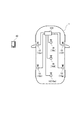
図1には、本実施例の携帯端末位置検出装置100を搭載した車両1の大まかな構造が示されている。図示されるように、車両1には7箇所に受信器10が搭載されている。尚、本実施例では、車両1に搭載された受信器10の数は7つであるものとして説明するが、受信器10の数は7つに限らず、例えば、より多くの受信器10を搭載しても良い。また、これらの受信器10を区別する必要がある場合には、受信器10a、受信器10b、受信器10c、受信器10d、受信器10e、受信器10f、受信器10gと表記するが、特に区別する必要がない場合は、単に受信器10、あるいは受信器10a〜10gと表記する。
これらの受信器10a〜10gは、電波を送受信するためのアンテナと、アンテナに接続されて電波の送受信を制御する制御ユニットとを備えており、それぞれの受信器10a〜10gの制御ユニットは携帯端末位置検出装置100に接続されている。このため、携帯端末位置検出装置100は、受信器10a〜10gを用いて、車両1の外部あるいは内部に存在する携帯端末20からの電波を受信したり、携帯端末20に向かって電波を送信したりすることができる。また、受信器10a〜10gが携帯端末20からの電波を受信した時の信号強度を検出すれば、携帯端末20の存在位置を決定することも可能である。
Hereinafter, examples will be described in order to clarify the content of the present invention described above.
A. Device configuration :
FIG. 1 shows a rough structure of a vehicle 1 equipped with a mobile terminal
These
もっとも、電波の信号強度は、受信器10や携帯端末20の周辺環境の影響で変化する。このため、信号強度に基づいて決定した携帯端末20の存在位置には大きな誤差が含まれることがあり、携帯端末20が車両1の室内に存在するのか、あるいは室外に存在するのかを識別可能な程度の位置精度を確保することは難しい。
また、受信器10の数を増やして、検出する信号強度の数を増やせば、信号強度のバラツキによる位置精度の低下は抑制することができるが、その反面で、受信器10の数を増やしたことに起因する誤差が大きくなってしまう。
このため、図1に示すように、複数の受信器10で電波の信号強度を検出する方法では、電波の信号強度に基づいて携帯端末20の存在位置を検出する方法では、十分な位置精度を確保することが困難となっていた。
However, the signal strength of the radio wave changes due to the influence of the surrounding environment of the
Further, by increasing the number of
Therefore, as shown in FIG. 1, in the method of detecting the signal strength of the radio wave with the plurality of
ところが、本実施例の携帯端末位置検出装置100では、受信器10の数を増やすことによって、携帯端末20の存在位置の検出精度を、(少なくとも原理上は)幾らでも向上させることが可能である。それでいながら、何ら処理が複雑になることもない。以下では、こうした優れた特性を有する本実施例の携帯端末位置検出装置100について説明するが、そのための準備として、従来の方法について概要を説明しておく。
However, in the mobile terminal
図2には、受信器10が携帯端末20からの電波を受信するために、携帯端末20との間で接続を確立させる様子が例示されている。尚、図2では、一例として、2.4GHzの周波数帯の電波を用いて無線通信する通信規格の場合について説明するが、他の通信規格であっても構わない。
図2に例示した通信規格は、いわゆるマスター−クライアント方式を採用しており、マスター側の受信器10は、通信しない間は電力消費を抑制する目的から、休止状態となっている。
FIG. 2 exemplifies how the
The communication standard illustrated in FIG. 2 employs a so-called master-client method, and the
また、クライアント側である携帯端末20は、接続されることを待機中であることを示す待機信号を、所定周期で送信する。この待機信号には、マスター側からの接続を待機中であることに加えて、自らが携帯端末20であることや、マスター側の機器(ここでは受信器10)に対して提供可能な機能などに関する情報が含まれている。従って、マスター側の受信器10は、待機信号を受信することによって携帯端末20が存在することを認識するとともに、その携帯端末20に接続するか否かを判断することができる。
In addition, the
もっとも、受信器10が休止状態となっている間は、待機信号を送信しても、受信器10で受信されることはない。従って、携帯端末20が連続して待機信号を送信しても、その信号は無駄になる。また、そもそも受信器10が存在しない場合や、受信器10が待機信号を受け取った結果、接続しないと判断した場合にも、同様なことが当て嵌まる。そこで、図2に例示した通信規格では、クライアント側(ここでは携帯端末20)の電力消費を抑制する目的から、待機信号は連続して送信するのではなく、所定の時間が経過する度に送信することとしている。
尚、待機信号を送信してから、再び送信するまでの経過時間は、数十ミリ秒〜数秒の範囲で選択可能である。また、この待機信号は、通信規格によっては、アドバタイズ信号と呼ばれることがある。
However, while the
The elapsed time from the transmission of the standby signal to the transmission again can be selected within the range of several tens of milliseconds to several seconds. Also, this standby signal may be called an advertise signal depending on the communication standard.
また、図1を用いて前述したように、受信器10は携帯端末位置検出装置100に接続されており、携帯端末20に接続する旨の要求を携帯端末位置検出装置100から受け取ると、休止状態から探索状態に切り替わって、待機信号の探索を開始する。
図2に示されるように、待機信号の探索では、携帯端末20からの待機信号を所定時間に亘って探索するが、待機信号が見つからなかった場合には、一旦、探索を中断し、所定時間が経過してから、再び待機信号の探索を開始する。このように、待機信号が見つかるまで連続して探索するのではなく、所定時間が経過する度に探索することとしているのは、受信器10の電力消費を抑制するためである。すなわち、待機信号が受信できない場合や、受信できたとしても、その待機信号が携帯端末20からの待機信号ではなかった場合には、その状態が暫くの間は継続する可能性が高いと考えられるので、待機信号の受信を待ち続けても無駄に電力を消費することになる。そこで、一旦、受信を中断して電力の消費を回避し、所定時間が経過したら、再び待機信号の探索を開始することとしている。
Further, as described above with reference to FIG. 1, the
As shown in FIG. 2, in the search for the standby signal, the standby signal from the
尚、前述したように、携帯端末20も間欠的に(すなわち、一定の時間間隔が経過する度に)待機信号を送信しているので、受信器10が待機信号を探索する期間と、携帯端末20が待機信号を送信する期間とが食い違ってしまうことが起こり得る。しかし、携帯端末20が待機信号を送信する周期と、受信器10が待機信号を探索する周期とは異なる周期に設定されている。このため、やがては、携帯端末20が待機信号を送信する期間と、受信器10が待機信号を探索する期間とが重なって、受信器10は携帯端末20の待機信号を受信することができる。
そして、受信器10は、携帯端末20からの待機信号を受信して、その携帯端末20に接続しようと判断した場合は、接続を要求する接続要求信号を送信する。すると、その接続要求信号を受け取った携帯端末20は、受信器10が接続してきたことを認識して待機状態を終了すると共に、接続状態に移行して、その受信器10との間で接続を確立するため接続処理を開始する。また、受信器10の側でも、接続要求信号を送信した後は、探索状態を終了して接続状態に移行し、携帯端末20との間で接続を確立するための接続処理を開始する。
As described above, since the
Then, when the
こうして、携帯端末20および受信器10が接続状態に移行すると、互いの識別番号や、無線通信に使用する周波数チャンネルや、通信間隔や、通信するデータのデータ構造など、無線通信する際に必要な様々な情報をやり取りすることによって、接続を確立する。
そして接続を確立したら、携帯端末20および受信器10は何れも通信状態に移行して、データ通信を開始する。また、データ通信を終了したら、携帯端末20は待機状態に復帰し、受信器10は休止状態に復帰して、上述した一連の処理を再開する。
In this way, when the
Then, when the connection is established, both the
このように、受信器10と携帯端末20とは、いわゆるマスター−クライアント方式の通信規格を採用している関係上、クライアント側の携帯端末20は、「待機状態」、「接続状態」、「通信状態」の3つの状態を備えており、マスター側の受信器10は、「休止状態」、「探索状態」、「接続状態」、「通信状態」の4つの状態を備えている。そして、クライアント側の携帯端末20と、マスター側の受信器10とが、互いに歩調を合わせるようにして、これらの状態を切り替えることによって通信している。
しかし、このような通信方式を採用した結果とし、携帯端末20からの電波の信号強度を複数の受信器10で検出しようとすると、受信器10の数が増えるほど検出に要する時間が増加するという事態が発生していた。
As described above, since the
However, as a result of adopting such a communication system, if the signal strength of the radio wave from the
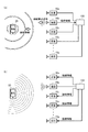
図3には、従来の携帯端末位置検出装置500が、複数箇所に設置された受信器10(図3では、受信器10a、10b、10c・・・)で、携帯端末20からの電波の信号強度を検出する様子が例示されている。尚、従来の携帯端末位置検出装置500も、図1を用いて前述した本実施例の携帯端末位置検出装置100と同様に、7つの受信器10a〜10gに接続されているものとする。
In FIG. 3, a conventional mobile terminal
図2を用いて前述したように、携帯端末20からの電波を受信する必要がない場合は、受信器10は休止状態となっている。また、受信器10が休止状態となっている間も、携帯端末20は待機状態となっており、受信器10からの接続を待機中であることを表す待機信号を送信している。
この状態で、携帯端末位置検出装置500が携帯端末20の電波の信号強度を検出する必要が生じると、携帯端末位置検出装置500は7つの受信器10a〜10gに対して、携帯端末20に接続するように要求する。すると、要求を受けた受信器10a〜10gは休止状態から探索状態に移行して、携帯端末20からの待機信号の探索を開始する。
As described above with reference to FIG. 2, when it is not necessary to receive the radio wave from the
In this state, when it becomes necessary for the mobile terminal
しかし、図2を用いて前述したように、携帯端末20は間欠的に待機信号を送信し、受信器10も間欠的に待機信号を探索するので、受信器10a〜10gは探索状態に入っても直ちに携帯端末20を見つけられる訳ではない。携帯端末20が待機信号を送信している期間に、待機信号の探索を開始した受信器10でなければ、携帯端末20を見つけることはできない。図3に示した例では、受信器10bが一番早いタイミングで携帯端末20を見つけられたものとしている。
そして、図2を用いて前述したように、携帯端末20を見つけた受信器10bは、携帯端末20に接続要求信号を送信して「接続状態」に移行する。また、携帯端末20の方でも、受信器10bからの接続要求信号を受信すると「接続状態」に移行して、受信器10bと携帯端末20との間で接続を確立する。こうして接続を確立したら、携帯端末20および受信器10bが「通信状態」に移行して互いに通信可能な状態になる。そこで、受信器10bは、携帯端末20の電波の信号強度を検出して、携帯端末位置検出装置500に出力した後、通信状態を終了して休止状態に移行する。また、受信器10bが休止状態に移行したことに対応して、受信器10bに接続していた携帯端末20は待機状態に移行する。
However, as described above with reference to FIG. 2, since the
Then, as described above with reference to FIG. 2, the
このように受信器10bが携帯端末20との間で接続を確立して、電波の信号強度を検出している間も、他の受信器10a、10c〜10gは探索状態のままで携帯端末20からの待機信号を探索している。しかし、図2を用いて前述したように、携帯端末20は接続状態および通信状態では待機信号を送信しないので、他の受信器10a、10c〜10gは携帯端末20を見つけることができない。そして、携帯端末20が受信器10bとの通信を終了して待機状態に復帰して初めて、携帯端末20を探索可能となる。
In this way, while the
図3に示した例では、その結果、受信器10aが携帯端末20を見つけたものとしている。すると、今度は、受信器10aが携帯端末20との間で接続を確立して通信を開始して、携帯端末20の電波の信号強度を検出した後、検出した信号強度を携帯端末位置検出装置500に出力する。また、受信器10aと接続を確立して通信している間は、携帯端末20は待機状態とはなっていないので、待機信号は送信していない。その結果、他の受信器10c〜10gは携帯端末20を見つけることができず、携帯端末20が受信器10aとの通信を終了して待機状態に復帰して初めて、携帯端末20を探索可能となる。
In the example shown in FIG. 3, as a result, it is assumed that the
このように、従来の携帯端末位置検出装置500では、複数の受信器10で、携帯端末20からの電波の信号強度を検出しようとすると、検出に要する時間が半ば必然的に増加する。更に、携帯端末20の存在位置を検出する位置精度を高めようとして、受信器10の数を増やせば増やすほど、検出に要する時間が長くなる。そして、この間に携帯端末20が移動する可能性があるが、携帯端末位置検出装置500の側では携帯端末20が移動しているか否かは判断できない。その結果、携帯端末20の移動し得る範囲によって、存在位置の検出精度が制限されてしまうこととなって、結局は、受信器10の数を増やしても携帯端末20の存在位置を十分な精度で検出することが困難となっていた。
これに対して、本実施例の携帯端末位置検出装置100は、複数の受信器10で携帯端末20の電波の信号強度を検出することによって、携帯端末20の存在位置を十分な精度で検出することが可能である。
As described above, in the conventional mobile terminal
On the other hand, the mobile terminal
図4には、本実施例の携帯端末位置検出装置100の大まかな内部構造が示されている。図示されるように、携帯端末位置検出装置100は、通信部101と、接続要求部102と、接続情報取得部103と、接続情報出力部104と、信号強度取得部105と、存在位置検出部106とを備えている。
尚、これらの「部」は、本実施例の携帯端末位置検出装置100が、電波の信号強度に基づいて携帯端末の存在位置を検出する機能に着目して、携帯端末位置検出装置100の内部を便宜的に分類した抽象的な概念である。従って、携帯端末位置検出装置100の内部が、これらの「部」に物理的に区分されていることを表すものではない。これらの「部」は、CPUで実行されるコンピュータープログラムとして実現することもできるし、LSIを含む電子回路として実現することもできるし、更にはこれらの組合せとして実現することもできる。
FIG. 4 shows a rough internal structure of the portable terminal
Note that these “sections” are focused on the function of the mobile terminal
通信部101は、受信器10a〜10gとケーブルによって接続されており、所定の通信規格に従って互いに通信することが可能である。
接続要求部102は、携帯端末20の存在位置を検出する必要が生じると、受信器10a〜10gに対して携帯端末20に接続するように要求する。接続要求部102が出力した要求は、通信部101を介して受信器10a〜10gに送信される。すると受信器10a〜10gは、要求に従って携帯端末20に接続するべく、携帯端末20の探索を開始する。そして、携帯端末20を見つけた受信器10は、携帯端末20と接続するために用いる接続情報を取得することによって、携帯端末20との間で接続を確立する。
The
When it is necessary to detect the existing position of the
接続情報取得部103は、携帯端末20との間で接続を確立した受信器10から、接続情報を取得する。接続情報を取得する際には、接続を確立した受信器10を接続情報取得部103が検出して接続情報を要求しても良いし、接続要求部102が受信器10a〜10gに対して接続を要する際に、接続を確立した場合には接続情報を返信する旨も合わせて要求しておいても良い。更には、受信器10a〜10gの中に、接続情報を取得した場合には携帯端末位置検出装置100に出力する機能を予め組み込んでおくようにしても良い。接続情報取得部103は、接続情報を取得すると、その情報を接続情報出力部104に出力する。
The connection
接続情報出力部104は、接続情報を受け取ると、まだ携帯端末20に接続できていない受信器10に向かって接続情報を出力する。すなわち、複数の受信器10a〜10gが一斉に携帯端末20に接続しようとしても同時に接続できるわけではないから、接続情報取得部103が接続情報を取得した時点では、未だ携帯端末20に接続できていない受信器10が存在する。接続情報出力部104は、このような受信器10に対して接続情報を出力する。そして、接続情報を受け取った受信器10は、自らは携帯端末20に接続していないにも拘わらず、携帯端末20からの電波を受信可能な状態となる。
Upon receiving the connection information, the connection
信号強度取得部105は、受信器10a〜10gが検出した携帯端末20の電波の信号強度を取得する。上述したように、受信器10a〜10gは何れも接続情報を取得済みとなっているから、携帯端末20が電波を出力すると、その電波を受信して信号強度を検出することができる。そして、信号強度取得部105は、受信器10a〜10gで検出された信号強度を取得すると、それら信号強度を存在位置検出部106に出力する。
存在位置検出部106は、信号強度取得部105から取得した信号強度に基づいて、携帯端末20の存在位置を検出する。
The signal
The existing
本実施例の携帯端末位置検出装置100は、以上のような各種の機能を備えているので、受信器10の数を増やすことによって、携帯端末20の存在位置の検出精度を向上させることが可能となる。以下では、この理由を説明するために、本実施例の携帯端末位置検出装置100が、携帯端末20の存在位置を検出するために実行している処理の詳細について説明する。
Since the mobile terminal
B.携帯端末位置検出処理 :
図5には、本実施例の携帯端末位置検出装置100が実行する携帯端末位置検出処理のフローチャートが示されている。
図示されるように携帯端末位置検出処理を開始すると、先ず初めに、携帯端末20の存在位置を検出するか否かを判断する(S100)。本実施例では、一定時間(例えば5秒)が経過する度に存在位置を検出するものとして説明するが、他のプログラムから要請があった場合に、携帯端末20の存在位置を検出するようにしても良い。
その結果、携帯端末20の存在位置を検出しないと判断した場合は(S100:no)、同じ判断(S100)を繰り返すことによって待機状態となる。
B. Mobile device position detection process:
FIG. 5 shows a flowchart of the mobile terminal position detection processing executed by the mobile terminal
When the mobile terminal position detection processing is started as shown in the figure, first, it is determined whether or not the existing position of the
As a result, when it is determined that the existing position of the
これに対して、携帯端末20の存在位置を検出すると判断した場合は(S100:yes)、携帯端末位置検出装置100に接続されている各受信器10a〜10gに対して、携帯端末20への接続を要求する(S101)。要求を受けた受信器10a〜10gは、図3を用いて前述したように、休止状態から探索状態に移行して、携帯端末20から送信される待機信号の探索を開始する。但し、探索を開始しても、直ちに待機信号を受信できるとは限らない。従って、受信器10a〜10gの中で、最初に待機信号を受信した受信器10が、最初に接続要求信号を送信することによって携帯端末20と接続することになる。
On the other hand, when it is determined that the existing position of the
携帯端末位置検出装置100は、受信器10a〜10gに対して接続を要求すると(S101)、携帯端末20と接続できた受信器10が存在するか否かを判断する(S102)。判断に際しては、接続できたか否かを、それぞれの受信器10a〜10gに対して携帯端末位置検出装置100から問い合わせることによって判断しても良いし、あるいは受信器10a〜10gに接続を要求する際に、接続できた場合にはその旨を返信するように供給しておき、返信の有無に基づいて判断しても良い。
When the mobile terminal
その結果、携帯端末20に接続できた受信器10が未だ存在しない場合は(S102:no)、接続を要求してから所定時間(例えば2秒)が経過したか否かを判断する(S103)。そして、所定時間が経過していなかった場合は(S103:no)、S102に戻って、携帯端末20に接続できた受信器10が存在するか否かを判断する。このようにして、S102およびS103の判断を繰り返しているうちに、受信器10a〜10gに対して接続を要求してから所定時間が経過した場合には(S103:yes)、接続すべき携帯端末20が存在しないと考えられるので、処理の先頭に戻って、上述した一連の処理を再開する。
As a result, if the
これに対して、携帯端末20に接続できた受信器10(以下では、接続受信器と称する)が存在する場合は(S102:yes)、その接続受信器から接続情報を取得する(S104)。ここで、接続情報とは、携帯端末20との間で接続を確立した受信器10(すなわち接続受信器)が、携帯端末20と通信するために用いる情報である。接続情報の内容は通信規格によって異なるが、例えば、互いの識別番号や、無線通信に使用する周波数チャンネルや通信間隔、通信するデータのデータ構造などである。また、暗号化して通信する場合は、暗号化キーも接続情報に含まれる。
On the other hand, when there is a receiver 10 (hereinafter, referred to as a connection receiver) that can be connected to the mobile terminal 20 (S102: yes), the connection information is acquired from the connection receiver (S104). Here, the connection information is information used by the receiver 10 (that is, the connection receiver) that has established a connection with the
携帯端末位置検出装置100は、こうして接続受信器から接続情報を取得すると(S104)、その接続情報を、未だ携帯端末20と接続できていない受信器10(以下では、未接続受信器と称する)に向かって出力する(S105)。すなわち、接続情報とは、受信器10a〜10gの中で最初に携帯端末20に接続した受信器10が、携帯端末20との通信に使用する情報であるが、その接続情報を、未だ携帯端末20に接続していない別の受信器10に向かって出力するのである。
When the mobile terminal
図6には、本実施例の携帯端末位置検出装置100が、接続受信器から接続情報を取得して、未接続受信器に出力する様子が示されている。図6(a)では、携帯端末20を探索していた受信器10a〜10gの中で、最初に受信器10bが携帯端末20を見つけ出して、携帯端末20に向かって接続要求信号を送信している様子が示されている。
接続要求信号を受信した携帯端末20は、待機信号を送信する待機状態から接続状態に移行して、接続を確立するために接続情報を送信する。すると、受信器10bは、送信されてきた接続情報を受信することによって、携帯端末20との間で接続を確立する。従って、図6に示した例では、受信器10bが接続受信器となり、受信器10aや受信器10c〜10gが未接続受信器となる。そして、受信器10bは携帯端末20との接続を確立すると、携帯端末20との通信に使用する接続情報を、携帯端末位置検出装置100に出力する。
FIG. 6 shows how the portable terminal
The
すると、携帯端末位置検出装置100は、取得した接続情報を、未だ携帯端末20に接続していない受信器10a、受信器10c〜10gに出力する。その結果、これらの受信器10a、受信器10c〜10gは、探索状態から、携帯端末20の電波を受信可能な受信状態に移行する。すなわち、探索状態にある受信器10aおよび受信器10c〜10gが携帯端末20の電波を受信可能となるためには、従来の方法では、探索状態から接続状態を経て通信状態に移行する必要があったが、本実施例では、接続状態を経ることなく受信状態に移行することになる。また、受信器10bについては、接続状態を経て通信状態に移行しているので、携帯端末20からの電波を受信することができる。
尚、受信状態の受信器10は、携帯端末20と接続を確立した訳ではないので、携帯端末20に対しては送信できないものとしておくことが望ましい。こうすれば、接続を確立した受信器10が携帯端末20と送信している間に、接続を確立していない受信器10が携帯端末20に対して電波を送信して、いわゆる通信の衝突が発生することを防止することができる。
Then, the mobile terminal
Since the
こうして、未接続受信器(図6に示した例では、受信器10aおよび受信器10c〜10g)に接続情報を出力することによって(図5のS105)、受信器10a〜10gで携帯端末20の電波を受信することが可能となったら、接続受信器(図6に示した例では、受信器10b)で検出された電波の信号強度を取得する(S106)。続いて、未接続受信器(図6に示した例では、受信器10aおよび受信器10c〜10g)で検出された電波の信号強度を取得する(S107)。
そして、それぞれの受信器10a〜10gで取得された信号強度に基づいて、携帯端末20の存在位置を検出する(S108)。信号強度に基づいて携帯端末20の存在位置を検出する方法には、従来から用いられている方法を適用することができる。
その後、得られた携帯端末20の存在位置を外部(例えば、他のプログラムや、車両1に搭載されている他の車載機器)に出力した後(S109)、処理の先頭のS100に戻って、上述した続く一連の処理を再開する。
In this way, by outputting the connection information to the unconnected receivers (in the example shown in FIG. 6, the
Then, the existing position of the
After that, after outputting the obtained location of the
本実施例の携帯端末位置検出装置100は、以上のようにして携帯端末20の存在位置を検出しているので、複数の受信器10で携帯端末20の電波の信号強度を利用しているにも拘わらず、十分な精度で携帯端末20の存在位置を検出することができる。
図7には、本実施例の携帯端末位置検出装置100が十分な精度で携帯端末20の存在位置を検出可能な理由が示されている。
図示されるように、携帯端末位置検出装置100が携帯端末20の存在位置を検出しようとして、受信器10a〜10gに接続を要求すると、それまで休止状態だった受信器10a〜10gは、携帯端末20が送信する待機信号の探索を開始する。図7では、携帯端末20が送信する待機信号を、破線の矢印で表している。
Since the mobile terminal
FIG. 7 shows the reason why the mobile terminal
As shown in the figure, when the mobile terminal
そして、受信器10a〜10gの中で最初に待機信号を受信した受信器10は、探索状態から接続状態に移行して、携帯端末20から接続情報を取得し、更にその接続情報を携帯端末位置検出装置100に出力する。図7中では、受信器10eが最初に待機信号を受信した場合を示しており、その受信器10eに向かって携帯端末20が接続情報を送信する様子や、携帯端末20から受け取った接続情報を受信器10eが携帯端末位置検出装置100に出力する様子を、斜線を付した矢印によって表している。
Then, the
携帯端末位置検出装置100は、受信器10eから接続情報を受け取ると、今度は、受信器10a〜10d、10f、10gに向かって、その接続情報を出力する。その結果、これらの受信器10a〜10d、10f、10gは、携帯端末20からの電波を受信可能な受信状態となる。また、携帯端末20から接続情報を受信した受信器10eは通信状態となっているので、受信器10eも携帯端末20からの電波を受信可能となっている。
そして、このように全ての受信器10a〜10gが携帯端末20からの電波を受信可能となった状態で、電波の信号強度を検出する。その結果、携帯端末20が出力した同じ電波を、受信器10a〜10gで受信した時の信号強度を検出することができる。そして、このことは、受信器10の数が増えても変わることはない。
このような理由から、本実施例の携帯端末位置検出装置100では、受信器10の数を増やすことによって位置精度を高めることができるので、十分な精度で携帯端末20の存在位置を検出することが可能となる。
Upon receiving the connection information from the
Then, the signal strength of the radio wave is detected in a state where all the
For this reason, in the mobile terminal
C.変形例 :
上述した本実施例の携帯端末位置検出装置100は、通信部101を介して受信器10a〜10gに接続されているものとして説明した。この場合、通信部101と受信器10a〜10gとの間で行われる通信も、マスター−クライアント方式の通信規則に則って行われることになる。また、携帯端末20の存在位置を検出する際には、通信部101を介して、受信器10a〜10gに対して一斉に接続を要求していた。
これに対して、通信部101を介さずに携帯端末位置検出装置100と通信可能な受信器10aを設けておき、他の受信器10(すなわち、受信器10b〜10g)は通信部101を介して携帯端末位置検出装置100と通信するようにしても良い。そして、携帯端末20の存在位置を検出する際には、受信器10b〜10gに対しては接続を要求することなく、受信器10aに対して接続を要求するようにしてもよい。
C. Modification:
The mobile terminal
On the other hand, the
図8には、このようは変形例の携帯端末位置検出装置150の大まかな内部構造が示されている。変形例の携帯端末位置検出装置150は、図4を用いて前述した本実施例の携帯端末位置検出装置100に対して、受信器10aが接続要求部102に直接接続されている点で異なるが、その他の点については同様である。
このような変形例の携帯端末位置検出装置150では、受信器10aと接続要求部102とが直接接続されている。このため、受信器10b〜10gが通信部101との間で通信する時のようなマスター−クライアント方式の通信規則に縛られることなく、高速に通信することができる。
FIG. 8 shows a rough internal structure of the portable terminal
In the mobile terminal
図9には、変形例の携帯端末位置検出装置150が実行する携帯端末位置検出処理のフローチャートが示されている。この処理は、図5を用いて前述した携帯端末位置検出処理に対して、所定の受信器10(ここでは受信器10a)に対しては携帯端末20への接続を要求するが、その他の受信器10(ここでは受信器10b〜10g)に対しては要求しない点が大きく異なっている。以下では、この相違点を中心に、変形例の携帯端末位置検出処理に付いて簡単に説明する。
FIG. 9 shows a flowchart of mobile terminal position detection processing executed by mobile terminal
図9に示されるように、変形例の携帯端末位置検出処理でも、前述した本実施例の場合と同様に、先ず初めに、携帯端末20の存在位置を検出するか否かを判断する(S150)。そして、携帯端末20の存在位置を検出しないと判断した場合は(S150:no)、同じ判断(S100)を繰り返すことによって待機状態となる。
これに対して、携帯端末20の存在位置を検出すると判断した場合は(S150:yes)、受信器10aに対して携帯端末20への接続を要求する(S151)。図8を用いて前述したように、受信器10b〜10gとは異なり、受信器10aは携帯端末位置検出装置150と、いわゆるピア・ツー・ピアで接続されているので、受信器10b〜10gよりも高速に通信することができる。
As shown in FIG. 9, also in the mobile terminal position detection processing of the modified example, as in the case of the present embodiment described above, first, it is determined whether or not the existing position of the
On the other hand, when it is determined that the existing position of the
続いて、所定の受信器10aが携帯端末20に接続できた否かを判断し(S152)、接続できていなかった場合は(S152:no)、接続を要求してから所定時間が経過したか否かを判断する(S153)。その結果、所定時間が経過していなかった場合は(S153:no)、再び、受信器10aが携帯端末20に接続できたか否かを判断する(S152)。このような判断を繰り返しているうちに、所定時間が経過した場合には(S153:yes)、接続すべき携帯端末20が存在しないと考えられるので、処理の先頭に戻って、上述した一連の処理を再開する。
Subsequently, it is determined whether or not the
これに対して、所定の受信器10(ここでは受信器10a)が携帯端末20に接続できた場合は(S152:yes)、受信器10aから接続情報を取得した後(S154)、その接続情報を、他の受信器10(ここでは、受信器10b〜10g)に向かって出力する(S155)。その結果、これらの受信器10b〜10gも、携帯端末20の電波を受信可能な受信状態となる。
On the other hand, when the predetermined receiver 10 (here, the
こうして、受信器10a〜10gで携帯端末20の電波を受信することが可能となったら、受信器10aで検出された電波の信号強度を取得し(S156)、続いて、他の受信器10b〜10g)で検出された電波の信号強度を取得する(S157)。そして、それぞれの受信器10a〜10gで取得された信号強度に基づいて、携帯端末20の存在位置を検出した後(S158)、携帯端末20の存在位置を外部に出力して(S159)、処理の先頭のS150に復帰する。
Thus, when the radio waves of the
このような変形例の携帯端末位置検出装置150では、受信器10a〜10gの中で高速に通信可能な受信器10aを用いて接続情報を取得するので、より一層迅速に、携帯端末20の存在位置を検出することが可能となる。
In the mobile terminal
1…車両、 10a〜10g…受信器、 20…携帯端末、
100…携帯端末位置検出装置、 101…通信部、 102…接続要求部、
103…接続情報取得部、 104…接続情報出力部、
105…信号強度取得部、 106…存在位置検出部、
150…携帯端末位置検出装置。
1... Vehicle, 10a-10g... Receiver, 20... Portable terminal,
100... Mobile terminal position detection device, 101... Communication unit, 102... Connection request unit,
103... Connection information acquisition unit, 104... Connection information output unit,
105... Signal strength acquisition unit, 106... Presence position detection unit,
150... Mobile terminal position detection device.
Claims (4)
前記携帯端末は、
前記受信器からの接続要求を待ち受けていることを表す待機信号を所定周期で送信する接続待機状態と、
前記受信器からの接続要求を受け取ると前記接続待機状態から移行して、前記受信器と通信するために用いる接続情報を前記受信器との間で交換する接続情報交換状態と、
前記受信器との間で前記接続情報の交換が終了すると前記接続情報交換状態から移行して、前記接続情報を用いて前記受信器と通信する端末側通信状態と
を有しており、
前記受信器は、
前記携帯端末からの前記待機信号を受信しない休止状態と、
前記携帯端末への接続が要求されると前記休止状態から移行して、前記携帯端末からの前記待機信号を待ち受ける状態となり、所定時間の間に前記待機信号が受信できない場合には前記待機信号の待受を一旦休止した後に前記待機信号の待受を再開する動作を、前記待機信号を受信するまで繰り返す探索状態と、
前記待機信号を受信すると前記探索状態から移行して、前記携帯端末に対して前記接続要求を送信した後、前記待機信号を送信した前記携帯端末と通信するために用いる前記接続情報を前記携帯端末との間で交換する接続状態と、
前記携帯端末との間で前記接続情報の交換が終了すると前記接続状態から移行して、前記接続情報を用いて前記携帯端末と通信する通信状態と
を有しており、
携帯端末位置検出装置は、
前記複数の受信器の中の少なくとも1つの受信器に対して、前記携帯端末への接続を要求することによって、前記受信器を前記休止状態から前記探索状態へと移行させる接続要求部(102)と、
前記複数の受信器の中で前記携帯端末からの前記待機信号を受信して前記接続状態に移行した前記受信器である接続受信器が発生すると、該接続受信器が前記携帯端末から取得した前記接続情報を、前記接続受信器から取得する接続情報取得部(103)と、
前記接続受信器から取得した前記接続情報を、未だ前記携帯端末と接続していない前記受信器である未接続受信器に対して出力することによって、前記探索状態の前記未接続受信器を、前記携帯端末からの電波を受信可能な受信可能状態に移行させる接続情報出力部(104)と、
前記接続受信器および前記未接続受信器のそれぞれが受信した前記携帯端末からの電波の信号強度を取得する信号強度取得部(105)と、
前記接続受信器および前記未接続受信器から取得された前記信号強度に基づいて、前記携帯端末の存在位置を検出する存在位置検出部(106)と
を備える携帯端末位置検出装置。 By connecting to a plurality of receivers (10) mounted on the vehicle (1) and acquiring the signal strength of the radio wave from the mobile terminal (20) received by the receivers, the location of the mobile terminal can be determined. A mobile terminal position detecting device (100, 150) for detecting,
The mobile terminal is
A connection standby state in which a standby signal indicating that a connection request from the receiver is waiting is transmitted at a predetermined cycle,
Upon receiving a connection request from the receiver, transition from the connection standby state, connection information exchange state for exchanging connection information used for communicating with the receiver with the receiver,
When the exchange of the connection information with the receiver is completed, a transition is made from the connection information exchange state, and a terminal side communication state in which the connection information is used to communicate with the receiver
Has
The receiver is
A hibernation state in which the standby signal from the mobile terminal is not received,
When a connection to the mobile terminal is requested, the mobile terminal shifts from the hibernate state and waits for the standby signal from the mobile terminal. If the standby signal cannot be received within a predetermined time, the standby signal A search state in which the operation of resuming the standby of the standby signal after suspending the standby once is repeated until the standby signal is received;
When the standby signal is received, the mobile terminal shifts from the search state, transmits the connection request to the mobile terminal, and then uses the connection information used to communicate with the mobile terminal that has transmitted the standby signal. Connection status exchanged between
When the exchange of the connection information with the mobile terminal is completed, a transition is made from the connection state, and a communication state in which the connection information is used to communicate with the mobile terminal
Has
The mobile terminal position detection device
A connection request unit (102) that shifts the receiver from the hibernation state to the search state by requesting at least one of the plurality of receivers to connect to the mobile terminal. When,
When a connection receiver, which is the receiver that has transitioned to the connection state by receiving the standby signal from the mobile terminal among the plurality of receivers, occurs, the connection receiver acquires the connection signal from the mobile terminal. A connection information acquisition unit (103) for acquiring connection information from the connection receiver;
By outputting the connection information acquired from the connection receiver to an unconnected receiver that is the receiver that is not yet connected to the mobile terminal, the unconnected receiver in the search state , A connection information output unit (104) for shifting to a receivable state in which radio waves from the mobile terminal can be received ;
A signal strength acquisition unit (105) for acquiring the signal strength of the radio wave from the portable terminal received by each of the connected receiver and the unconnected receiver,
An existing position detection unit (106) for detecting the existing position of the mobile terminal based on the signal strengths acquired from the connected receiver and the unconnected receiver;
A mobile terminal position detection device including the.
前記接続要求部は、前記複数の受信器の中の所定の受信器に対して、前記携帯端末への接続を要求し、
前記接続情報取得部は、前記所定の受信器から前記接続情報を取得する
ことを特徴とする携帯端末位置検出装置。 The mobile terminal position detecting device (150) according to claim 1,
The connection request unit requests a connection to the mobile terminal for a predetermined receiver among the plurality of receivers,
The mobile terminal position detection device, wherein the connection information acquisition unit acquires the connection information from the predetermined receiver.
前記探索状態の前記受信器は、前記携帯端末が前記待機信号を送信する前記所定周期とは異なる所定の周期で、前記待機信号を待ち受ける状態と前記待受を休止する状態とを繰り返す
ことを特徴とする携帯端末位置検出装置。 The mobile terminal position detection device according to claim 1 or 2, wherein
The receiver in the searching state repeats a state of waiting for the standby signal and a state of suspending the standby in a predetermined cycle different from the predetermined cycle in which the mobile terminal transmits the standby signal. Mobile terminal position detection device.
前記携帯端末は、
前記受信器からの接続要求を待ち受けていることを表す待機信号を所定周期で送信する接続待機状態と、
前記受信器からの接続要求を受け取ると前記接続待機状態から移行して、前記受信器と通信するために用いる接続情報を前記受信器との間で交換する接続情報交換状態と、
前記受信器との間で前記接続情報の交換が終了すると前記接続情報交換状態から移行して、前記接続情報を用いて前記受信器と通信する端末側通信状態と
を有する携帯端末であり、
前記受信器は、
前記携帯端末からの前記待機信号を受信しない休止状態と、
前記携帯端末への接続が要求されると前記休止状態から移行して、前記携帯端末からの前記待機信号を待ち受ける状態となり、所定時間の間に前記待機信号が受信できない場合には前記待機信号の待受を一旦休止した後に前記待機信号の待受を再開する動作を、前記待機信号を受信するまで繰り返す探索状態と、
前記待機信号を受信すると前記探索状態から移行して、前記携帯端末に対して前記接続要求を送信した後、前記待機信号を送信した前記携帯端末と通信するために用いる前記接続情報を前記携帯端末との間で交換する接続状態と、
前記携帯端末との間で前記接続情報の交換が終了すると前記接続状態から移行して、前記接続情報を用いて前記携帯端末と通信する通信状態と
を有する受信器であり、
携帯端末位置検出方法は、
前記複数の受信器の中の少なくとも1つの受信器に対して、前記携帯端末への接続を要求することによって、前記受信器を前記休止状態から前記探索状態へと移行させる工程(S101,S151)と、
前記複数の受信器の中で前記携帯端末からの前記待機信号を受信して前記接続状態に移行した前記受信器である接続受信器が発生すると、該接続受信器が前記携帯端末から取得した前記接続情報を、前記接続受信器から取得する工程(S104、S154)と、
前記接続受信器から取得した前記接続情報を、未だ前記携帯端末と接続していない前記受信器である未接続受信器に対して出力することによって、前記探索状態の前記未接続受信器を、前記携帯端末からの電波を受信可能な受信可能状態に移行させる工程(S105、S155)と、
前記接続受信器および前記未接続受信器のそれぞれが受信した前記携帯端末からの電波の信号強度を取得する工程(S106、S107、S156、S157)と、
前記接続受信器および前記未接続受信器から取得された前記信号強度に基づいて、前記携帯端末の存在位置を検出する工程(S108、S158)と
を備える携帯端末位置検出方法。 A mobile phone for detecting the location of the mobile terminal by acquiring the signal strength of the radio wave from the mobile terminal (20) received by the receiver from a plurality of receivers (10) mounted on the vehicle (1). A terminal position detection method,
The mobile terminal is
A connection standby state in which a standby signal indicating that a connection request from the receiver is waiting is transmitted at a predetermined cycle,
Upon receiving a connection request from the receiver, transition from the connection standby state, connection information exchange state for exchanging connection information used for communicating with the receiver with the receiver,
When the exchange of the connection information with the receiver is completed, a transition is made from the connection information exchange state, and a terminal side communication state in which the connection information is used to communicate with the receiver
A mobile terminal having
The receiver is
A hibernation state in which the standby signal from the mobile terminal is not received,
When a connection to the mobile terminal is requested, the mobile terminal shifts from the hibernate state and waits for the standby signal from the mobile terminal. If the standby signal cannot be received within a predetermined time, the standby signal A search state in which the operation of resuming the standby of the standby signal after suspending the standby once is repeated until the standby signal is received;
When the standby signal is received, the mobile terminal shifts from the search state, transmits the connection request to the mobile terminal, and then uses the connection information used to communicate with the mobile terminal that has transmitted the standby signal. Connection status exchanged between
When the exchange of the connection information with the mobile terminal is completed, a transition is made from the connection state, and a communication state in which the connection information is used to communicate with the mobile terminal
A receiver having
The mobile terminal position detection method is
Changing at least one of the plurality of receivers from the sleep state to the search state by requesting a connection to the portable terminal (S101, S151) When,
When a connection receiver, which is the receiver that has transitioned to the connection state by receiving the standby signal from the mobile terminal among the plurality of receivers, occurs, the connection receiver acquires the connection signal from the mobile terminal. Obtaining connection information from the connection receiver (S104, S154),
By outputting the connection information acquired from the connection receiver to an unconnected receiver that is the receiver that is not yet connected to the mobile terminal, the unconnected receiver in the search state , A step of shifting to a receivable state in which radio waves from the mobile terminal can be received (S105, S155),
Acquiring the signal strength of the radio wave from the portable terminal received by each of the connected receiver and the unconnected receiver (S106, S107, S156, S157),
A mobile terminal position detecting method, comprising: detecting the existing position of the mobile terminal based on the signal strengths acquired from the connected receiver and the unconnected receiver (S108, S158).
Priority Applications (5)
| Application Number | Priority Date | Filing Date | Title |
|---|---|---|---|
| JP2017080082A JP6711309B2 (en) | 2017-04-13 | 2017-04-13 | Mobile terminal position detecting device and mobile terminal position detecting method |
| PCT/JP2018/008208 WO2018190026A1 (en) | 2017-04-13 | 2018-03-05 | Mobile terminal position detection device and mobile terminal position detection method |
| KR1020197025981A KR102210122B1 (en) | 2017-04-13 | 2018-03-05 | Mobile terminal location detection device, mobile terminal location detection method |
| EP18784305.7A EP3611531B1 (en) | 2017-04-13 | 2018-03-05 | Mobile terminal position detection device and mobile terminal position detection method |
| US16/559,422 US10674314B2 (en) | 2017-04-13 | 2019-09-03 | Mobile terminal position detection device and mobile terminal position detection method |
Applications Claiming Priority (1)
| Application Number | Priority Date | Filing Date | Title |
|---|---|---|---|
| JP2017080082A JP6711309B2 (en) | 2017-04-13 | 2017-04-13 | Mobile terminal position detecting device and mobile terminal position detecting method |
Publications (3)
| Publication Number | Publication Date |
|---|---|
| JP2018179773A JP2018179773A (en) | 2018-11-15 |
| JP2018179773A5 JP2018179773A5 (en) | 2019-07-18 |
| JP6711309B2 true JP6711309B2 (en) | 2020-06-17 |
Family
ID=63792977
Family Applications (1)
| Application Number | Title | Priority Date | Filing Date |
|---|---|---|---|
| JP2017080082A Active JP6711309B2 (en) | 2017-04-13 | 2017-04-13 | Mobile terminal position detecting device and mobile terminal position detecting method |
Country Status (5)
| Country | Link |
|---|---|
| US (1) | US10674314B2 (en) |
| EP (1) | EP3611531B1 (en) |
| JP (1) | JP6711309B2 (en) |
| KR (1) | KR102210122B1 (en) |
| WO (1) | WO2018190026A1 (en) |
Families Citing this family (2)
| Publication number | Priority date | Publication date | Assignee | Title |
|---|---|---|---|---|
| WO2020096065A1 (en) * | 2018-11-09 | 2020-05-14 | 株式会社ソニー・インタラクティブエンタテインメント | Communication device, electronic device, and wireless connection method |
| JP2022098145A (en) * | 2020-12-21 | 2022-07-01 | 株式会社Soken | Vehicle side unit and positional relation identification system |
Family Cites Families (38)
| Publication number | Priority date | Publication date | Assignee | Title |
|---|---|---|---|---|
| US6690940B1 (en) * | 2000-09-22 | 2004-02-10 | James W. Brown | System for selective prevention of non-emergency use of an electronic device |
| JP2003248045A (en) * | 2002-02-22 | 2003-09-05 | Alpine Electronics Inc | Apparatus for detecting location of occupant in cabin and on-board apparatus control system |
| JP4015963B2 (en) * | 2003-03-24 | 2007-11-28 | 株式会社日立製作所 | POSITION CALCULATION METHOD, RECEPTION DEVICE, AND POSITION CALCULATION DEVICE |
| JP3955290B2 (en) | 2004-06-30 | 2007-08-08 | ソニー・エリクソン・モバイルコミュニケーションズ株式会社 | Communication system and communication terminal device |
| JP2009177588A (en) * | 2008-01-25 | 2009-08-06 | Fujitsu Ten Ltd | In-vehicle device and position detection method |
| US8045961B2 (en) | 2009-06-22 | 2011-10-25 | Mourad Ben Ayed | Systems for wireless authentication based on bluetooth proximity |
| DE102010034976A1 (en) | 2010-08-20 | 2012-02-23 | Hella Kgaa Hueck & Co. | Arrangement for the authorization control, in particular for motor vehicles |
| US9041556B2 (en) * | 2011-10-20 | 2015-05-26 | Apple Inc. | Method for locating a vehicle |
| US9241235B2 (en) | 2013-03-14 | 2016-01-19 | Voxx International Corporation | Passive entry cell phone and method and system therefor |
| US9358940B2 (en) | 2013-11-22 | 2016-06-07 | Qualcomm Incorporated | System and method for configuring an interior of a vehicle based on preferences provided with multiple mobile computing devices within the vehicle |
| US20150161832A1 (en) | 2013-12-05 | 2015-06-11 | Ford Global Technologies, Llc | Method and Apparatus for Virtual Key Delivery |
| JP6241299B2 (en) | 2014-02-03 | 2017-12-06 | 株式会社デンソー | Vehicle electronic key system |
| JP6258744B2 (en) * | 2014-03-27 | 2018-01-10 | 株式会社デンソー | Measuring system |
| US9595145B2 (en) | 2014-04-23 | 2017-03-14 | Panasonic Automotive Systems Company Of America, Division Of Panasonic Corporation Of North America | System for assigning a smartphone as a temporary key for a vehicle |
| US20150356797A1 (en) | 2014-06-05 | 2015-12-10 | International Business Machines Corporation | Virtual key fob with transferable user data profile |
| BR102014017465A2 (en) | 2014-07-16 | 2016-02-16 | Segtrônica Comércio De Equipamentos E Produtos Ltda | radio frequency electromechanical lock |
| JP7126351B2 (en) * | 2014-08-12 | 2022-08-26 | シグニファイ ホールディング ビー ヴィ | Method and apparatus for localization of mobile devices |
| US10002479B2 (en) | 2014-10-01 | 2018-06-19 | Continental Intelligent Transportation Systems, LLC | End to end system for service delivery to and from a vehicle using a dongle |
| US20160150407A1 (en) | 2014-11-26 | 2016-05-26 | Wind River Systems, Inc. | Method And System For Connecting A Mobile Communication Device To An Automobile |
| FR3030818B1 (en) | 2014-12-23 | 2016-12-23 | Valeo Comfort & Driving Assistance | METHOD FOR SECURELY TRANSMITTING A VIRTUAL KEY AND METHOD OF AUTHENTICATING A MOBILE TERMINAL |
| CN104574593B (en) | 2014-12-24 | 2017-02-22 | 浙江银江研究院有限公司 | Virtual key based on Bluetooth communication as well as anti-theft lock system and application method thereof |
| FR3034550B1 (en) | 2015-04-01 | 2018-09-21 | Valeo Comfort And Driving Assistance | METHOD FOR LOADING A KEY WITHIN A USER TERMINAL AND ASSOCIATED USER TERMINAL |
| CN106486771A (en) | 2015-08-28 | 2017-03-08 | 中兴通讯股份有限公司 | Multiband micro-line strip antenna |
| US10437977B2 (en) | 2015-10-13 | 2019-10-08 | Etas Embedded Systems Canada Inc. | System and method for digital key sharing for access control |
| US10200371B2 (en) | 2015-11-09 | 2019-02-05 | Silvercar, Inc. | Vehicle access systems and methods |
| EP3443376B1 (en) | 2016-04-15 | 2020-09-16 | Denso Corporation | System for establishing real-time location |
| US9875591B2 (en) | 2016-04-26 | 2018-01-23 | Ford Global Techologies, Llc | Systems and methods for phone-as-a-key range extension |
| DE102016217318A1 (en) | 2016-07-26 | 2018-02-01 | Volkswagen Aktiengesellschaft | Method, computer program and device for checking authorization of a mobile communication device |
| US9688247B1 (en) | 2016-08-03 | 2017-06-27 | Ford Global Technologies, Llc | Method and apparatus for digital temporary vehicle key utilization |
| WO2018040641A1 (en) | 2016-08-31 | 2018-03-08 | 长城汽车股份有限公司 | Mobile terminal, vehicle terminal, and virtual key sharing method and system |
| US9894492B1 (en) | 2016-09-22 | 2018-02-13 | Ford Global Technologies, Llc | System and method for determining mobile device location relative to vehicle cabin |
| US10328898B2 (en) | 2016-10-12 | 2019-06-25 | Denso International America, Inc. | Passive entry / passive start systems and methods for vehicles |
| US10328899B2 (en) | 2016-10-12 | 2019-06-25 | Denso International America, Inc. | Localization and passive entry / passive start systems and methods for vehicles |
| US10189443B2 (en) | 2016-11-10 | 2019-01-29 | GM Global Technology Operations LLC | Virtual key for vehicle servicing |
| US9988016B1 (en) | 2016-12-07 | 2018-06-05 | Ford Global Technologies, Llc | Authentication of mobile devices for vehicle communication |
| US10862198B2 (en) | 2017-03-14 | 2020-12-08 | R.A. Miller Industries, Inc. | Wideband, low profile, small area, circular polarized uhf antenna |
| US10244476B2 (en) | 2017-04-13 | 2019-03-26 | Ford Global Technologies, Llc | Reducing power consumption for phone as a key (PAAK) vehicle system |
| US10328900B1 (en) | 2017-12-04 | 2019-06-25 | Lear Corporation | System and methods for vehicle passive keyless entry triggered by smartphone proximity detection |
-
2017
- 2017-04-13 JP JP2017080082A patent/JP6711309B2/en active Active
-
2018
- 2018-03-05 WO PCT/JP2018/008208 patent/WO2018190026A1/en unknown
- 2018-03-05 KR KR1020197025981A patent/KR102210122B1/en active IP Right Grant
- 2018-03-05 EP EP18784305.7A patent/EP3611531B1/en active Active
-
2019
- 2019-09-03 US US16/559,422 patent/US10674314B2/en active Active
Also Published As
| Publication number | Publication date |
|---|---|
| EP3611531B1 (en) | 2021-06-30 |
| JP2018179773A (en) | 2018-11-15 |
| US10674314B2 (en) | 2020-06-02 |
| EP3611531A1 (en) | 2020-02-19 |
| US20190394616A1 (en) | 2019-12-26 |
| KR102210122B1 (en) | 2021-02-01 |
| EP3611531A4 (en) | 2020-05-27 |
| KR20190109544A (en) | 2019-09-25 |
| WO2018190026A1 (en) | 2018-10-18 |
Similar Documents
| Publication | Publication Date | Title |
|---|---|---|
| JP4856736B2 (en) | Wireless communication apparatus, wireless communication system, and wireless communication method | |
| US8559878B2 (en) | Wireless communication system, wireless communication apparatus, wireless communication method, and non-transitory computer readable recording medium | |
| JP5260250B2 (en) | Unused frequency band detection method and radio communication apparatus in cognitive radio system | |
| US20220070026A1 (en) | Methods for frequency offset tracking in nr mmwave for efficient beam management | |
| JP2009171506A (en) | Radio communication device, control program of radio communication device, and radio communication system | |
| JP6447554B2 (en) | Mobile communication system and mobile reception control apparatus | |
| JP6711309B2 (en) | Mobile terminal position detecting device and mobile terminal position detecting method | |
| JP2015061169A5 (en) | ||
| CN107005827B (en) | Terminal discovery at a gateway node | |
| JP5897405B2 (en) | Access point discovery method, system, and wireless terminal for controlling timing when wireless terminal searches for access point | |
| WO2022027592A1 (en) | Partial sensing enhancement for sl resource allocation | |
| JP5562124B2 (en) | COMMUNICATION DEVICE, COMMUNICATION METHOD, AND PROGRAM | |
| US11963090B2 (en) | Communication control device, terminal device, communication control method, and control program | |
| CN114270939B (en) | Method and device for sending through link synchronization signal | |
| US20210307096A1 (en) | Electronic device supporting dual-connectivity and method for operating the same | |
| US20210306889A1 (en) | Electronic device for measuring communication signal from outside and method for operating the same | |
| JP2018179773A5 (en) | ||
| JP2006295476A (en) | Inter-vehicle communication system | |
| JP2021150918A (en) | Communication device and program | |
| JP4699203B2 (en) | Wireless communication apparatus and wireless communication system | |
| JP4192113B2 (en) | Wireless communication system | |
| JPH1146176A (en) | Communication control method and time division multiple access communication system | |
| KR20190052076A (en) | Communication device, communication method, and program | |
| US20200374945A1 (en) | Interaction between a kiosk and a mobile user equipment | |
| WO2022004030A1 (en) | Control device, communication device, and information processing method |
Legal Events
| Date | Code | Title | Description |
|---|---|---|---|
| A521 | Request for written amendment filed |
Free format text: JAPANESE INTERMEDIATE CODE: A523 Effective date: 20190611 |
|
| A621 | Written request for application examination |
Free format text: JAPANESE INTERMEDIATE CODE: A621 Effective date: 20190611 |
|
| TRDD | Decision of grant or rejection written | ||
| A01 | Written decision to grant a patent or to grant a registration (utility model) |
Free format text: JAPANESE INTERMEDIATE CODE: A01 Effective date: 20200428 |
|
| A61 | First payment of annual fees (during grant procedure) |
Free format text: JAPANESE INTERMEDIATE CODE: A61 Effective date: 20200511 |
|
| R151 | Written notification of patent or utility model registration |
Ref document number: 6711309 Country of ref document: JP Free format text: JAPANESE INTERMEDIATE CODE: R151 |
|
| R250 | Receipt of annual fees |
Free format text: JAPANESE INTERMEDIATE CODE: R250 |