JP6711260B2 - Rotating electric machine - Google Patents
Rotating electric machine Download PDFInfo
- Publication number
- JP6711260B2 JP6711260B2 JP2016249970A JP2016249970A JP6711260B2 JP 6711260 B2 JP6711260 B2 JP 6711260B2 JP 2016249970 A JP2016249970 A JP 2016249970A JP 2016249970 A JP2016249970 A JP 2016249970A JP 6711260 B2 JP6711260 B2 JP 6711260B2
- Authority
- JP
- Japan
- Prior art keywords
- cooling pipe
- stator
- temperature sensor
- electric machine
- stator core
- Prior art date
- Legal status (The legal status is an assumption and is not a legal conclusion. Google has not performed a legal analysis and makes no representation as to the accuracy of the status listed.)
- Expired - Fee Related
Links
- 238000001816 cooling Methods 0.000 claims description 71
- 238000007789 sealing Methods 0.000 claims description 17
- 230000000903 blocking effect Effects 0.000 claims description 10
- 239000002826 coolant Substances 0.000 claims description 10
- 239000003507 refrigerant Substances 0.000 description 17
- 230000002093 peripheral effect Effects 0.000 description 7
- 241001247986 Calotropis procera Species 0.000 description 6
- WABPQHHGFIMREM-UHFFFAOYSA-N lead(0) Chemical compound [Pb] WABPQHHGFIMREM-UHFFFAOYSA-N 0.000 description 4
- 239000011347 resin Substances 0.000 description 3
- 229920005989 resin Polymers 0.000 description 3
- 229910000976 Electrical steel Inorganic materials 0.000 description 2
- 229910000831 Steel Inorganic materials 0.000 description 2
- 238000007599 discharging Methods 0.000 description 2
- 230000005484 gravity Effects 0.000 description 2
- 230000004048 modification Effects 0.000 description 2
- 238000012986 modification Methods 0.000 description 2
- 239000010959 steel Substances 0.000 description 2
- 239000000853 adhesive Substances 0.000 description 1
- 230000001070 adhesive effect Effects 0.000 description 1
- 239000011230 binding agent Substances 0.000 description 1
- 230000005540 biological transmission Effects 0.000 description 1
- 238000004140 cleaning Methods 0.000 description 1
- 230000005674 electromagnetic induction Effects 0.000 description 1
- 239000012530 fluid Substances 0.000 description 1
- 230000004907 flux Effects 0.000 description 1
- 230000017525 heat dissipation Effects 0.000 description 1
- 230000020169 heat generation Effects 0.000 description 1
- 238000010030 laminating Methods 0.000 description 1
- 239000007788 liquid Substances 0.000 description 1
- 239000010687 lubricating oil Substances 0.000 description 1
- 239000000696 magnetic material Substances 0.000 description 1
- 238000004519 manufacturing process Methods 0.000 description 1
- 239000000463 material Substances 0.000 description 1
- 239000002184 metal Substances 0.000 description 1
- 229910052751 metal Inorganic materials 0.000 description 1
- 238000000465 moulding Methods 0.000 description 1
- 230000000149 penetrating effect Effects 0.000 description 1
- 239000000843 powder Substances 0.000 description 1
- 238000010248 power generation Methods 0.000 description 1
- 230000001172 regenerating effect Effects 0.000 description 1
- 238000005096 rolling process Methods 0.000 description 1
- 238000003860 storage Methods 0.000 description 1
Images

Description
本発明は、回転電機に関する。 The present invention relates to a rotary electric machine.
従来、回転電機としては、特許文献1に記載されているように、ステータ、ステータの内周側に配設されたロータ、ステータに径方向に対向するようにステータの外周側に配置される冷却パイプ、及び冷却パイプ内に冷媒を取り込むポンプが、ケース内に配設されたものがある。ステータは、ステータコアと、ステータコアのティースに巻回されたコイルとを含み、冷却パイプは、ステータに沿うようにステータの軸方向に延在する。また、冷却パイプには、その内部と外部とを連通すると共に、ステータに径方向に対向する開口を有する複数の貫通孔が設けられる。ポンプが駆動すると、ケース内の冷媒が、冷却パイプ内に取り込まれて、上記複数の貫通孔を介してステータに向けて放出される。回転電機では、ロータの回転時にコイルに電流が流れると、ステータコアやコイルが発熱する。係る発熱は、回転電機の内部を貫通する磁束に影響を与え、運転効率(回転効率、発電効率)を低下させる。この回転電機では、ステータコアやコイルに冷媒を放出することで、ステータコアやコイルを冷却し、運転効率の低下を抑制している。 Conventionally, as a rotating electric machine, as described in Patent Document 1, a stator, a rotor arranged on the inner peripheral side of the stator, and a cooling arranged on the outer peripheral side of the stator so as to face the stator in the radial direction. In some cases, a pipe and a pump for taking the refrigerant into the cooling pipe are arranged in the case. The stator includes a stator core and coils wound around the teeth of the stator core, and the cooling pipe extends in the axial direction of the stator along the stator. In addition, the cooling pipe is provided with a plurality of through holes that communicate the inside and the outside thereof and that have openings in the stator that face each other in the radial direction. When the pump is driven, the coolant in the case is taken into the cooling pipe and discharged toward the stator through the plurality of through holes. In a rotating electric machine, when a current flows through the coil when the rotor rotates, the stator core and the coil generate heat. Such heat generation affects the magnetic flux penetrating the inside of the rotating electric machine and reduces the operating efficiency (rotation efficiency, power generation efficiency). In this rotary electric machine, the stator core and the coils are cooled by discharging the refrigerant to the stator core and the coils, thereby suppressing a decrease in operating efficiency.
上記ステータの冷却を実行する回転電機において、冷却性能を検知するために冷媒温度を測定する温度センサを設置したいという要請がある。しかし、温度センサの取り付け位置によっては、温度センサ通過後の冷媒温度とステータに供給される冷媒温度に乖離が生じ、適正なモータ保護制御を実行しにくい。 There is a demand for installing a temperature sensor for measuring the coolant temperature in the rotating electric machine that cools the stator to detect the cooling performance. However, depending on the mounting position of the temperature sensor, there is a difference between the temperature of the refrigerant after passing through the temperature sensor and the temperature of the refrigerant supplied to the stator, and it is difficult to perform appropriate motor protection control.
そこで、本発明の目的は、温度センサ通過後の冷媒温度と、ステータに供給される冷媒温度との差を小さくできる回転電機を提供することにある。 Then, the objective of this invention is providing the rotary electric machine which can reduce the difference of the refrigerant temperature after passing a temperature sensor, and the refrigerant temperature supplied to a stator.
本発明に係る回転電機は、環状のステータコアと、前記ステータコアのティースに巻回されるコイルとを含むステータと、前記ステータに前記ステータコアの径方向に対向し、前記ステータに沿うように延在する冷却パイプであって、前記冷却パイプの軸方向の一方側に配設される端側貫通孔を含む1以上の貫通孔が、前記ステータに前記径方向に対向するように前記冷却パイプの側壁に設けられた冷却パイプと、前記冷却パイプの前記軸方向の一方側の先端開口を封鎖する封鎖部材と、前記封鎖部材に取り付けられると共に、少なくとも一部が前記冷却パイプ内に配置される温度センサと、冷媒を前記冷却パイプの内部に供給し前記貫通孔から前記ステータ側に放出させる冷媒供給装置と、を備え、前記封鎖部材の圧入部には、中心部に軸方向に延在する凹部が形成され、前記温度センサの少なくとも一部が当該凹部内に配置される。
A rotary electric machine according to the present invention includes a stator including an annular stator core, a coil wound around a tooth of the stator core, a stator that faces the stator in a radial direction of the stator core, and extends along the stator. A cooling pipe, wherein at least one through hole including an end side through hole disposed on one side in the axial direction of the cooling pipe is provided on a side wall of the cooling pipe so as to face the stator in the radial direction. A cooling pipe provided, a blocking member for blocking a tip opening on one side in the axial direction of the cooling pipe, and a temperature sensor attached to the blocking member and at least a part of which is arranged in the cooling pipe. A cooling medium supply device for supplying a cooling medium into the cooling pipe and discharging the cooling medium to the stator side from the through hole , wherein the press-fitting portion of the blocking member has a recessed portion extending in the axial direction in the central portion. is, at least a portion of said temperature sensor is Ru disposed within the recess.
また、本発明において、前記封鎖部材には、中心部に前記軸方向に延在する凹部が形成されており、この凹部内に前記温度センサが配置され、前記温度センサの一端面が前記冷却パイプ内に露出することが好ましい。 Further, in the present invention, the sealing member is formed with a recess extending in the axial direction at the center thereof, the temperature sensor is disposed in the recess, and one end surface of the temperature sensor has the cooling pipe. It is preferable to expose the inside.
また、本発明において、前記温度センサからの配線は、前記封鎖部材内を通過して、前記冷却パイプの外部に導出されることが好ましい。 Further, in the present invention, it is preferable that the wiring from the temperature sensor passes through the inside of the sealing member and is led out of the cooling pipe.
本発明に係る回転電機によれば、冷却パイプがステータに沿うように設けられ、冷媒供給装置が冷媒を冷却パイプ内から1以上の貫通孔を通過させてステータ側に放出させる。また、1以上の貫通孔が冷却パイプの軸方向一方側に配設される端側貫通孔を含み、温度センサは、冷却パイプの軸方向一方側を封鎖する封鎖部材に設けられ、少なくとも一部が冷却パイプ内に配置される。したがって、温度センサが端側貫通孔に近接する位置に配置されるので、温度センサが端側貫通孔を通過する直前の冷媒温度を測定可能になる。よって、温度センサ通過後の冷媒温度と、ステータに供給される冷媒温度との差を小さくでき、冷媒温度の推定精度が向上し、適正なモータ保護制御を実行できる。 According to the rotating electric machine of the present invention, the cooling pipe is provided along the stator, and the refrigerant supply device discharges the refrigerant from the inside of the cooling pipe through the one or more through holes to the stator side. Further, at least one through hole includes an end side through hole disposed on one axial side of the cooling pipe, and the temperature sensor is provided on a sealing member that seals one axial side of the cooling pipe, and at least a part of the temperature sensor is provided. Are placed in the cooling pipe. Therefore, since the temperature sensor is arranged at a position close to the end side through hole, it is possible to measure the refrigerant temperature immediately before the temperature sensor passes through the end side through hole. Therefore, the difference between the refrigerant temperature after passing through the temperature sensor and the refrigerant temperature supplied to the stator can be reduced, the estimation accuracy of the refrigerant temperature can be improved, and proper motor protection control can be executed.
以下に、本発明に係る実施の形態について添付図面を参照しながら詳細に説明する。なお、以下において複数の実施形態や変形例などが含まれる場合、それらの特徴部分を適宜に組み合わせて新たな実施形態を構築することは当初から想定されている。また、以下の説明及び図面において、Z方向は、鉛直方向に一致し、図1及び図2において、紙面上側は、鉛直方向上方を示す。 Embodiments according to the present invention will be described in detail below with reference to the accompanying drawings. When a plurality of embodiments and modifications are included below, it is assumed from the beginning that a new embodiment is constructed by appropriately combining the characteristic parts. In the following description and drawings, the Z direction corresponds to the vertical direction, and in FIGS. 1 and 2, the upper side of the paper surface is the upper side in the vertical direction.
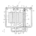
図1は、本発明の一実施形態に係る回転電機1の断面図であり、図2は、回転電機1における冷却パイプ7周辺の拡大断面図である。図1に示すように、回転電機1は、ケース2と、ケース2内に配置される電機本体3を備える。ケース2は、ケース本体21と上側カバー22を有し、ケース本体21はZ方向上側が開口し、当該開口は上側カバー22で覆われる。上側カバー22は、ケース本体21の開口周縁にボルト23で固定される。一方、電機本体3は、ステータ5、ロータ6、冷却パイプ7、封鎖部材8、温度センサ10、及び冷媒供給装置の一例としてのポンプ11を含む。ステータ5は、環状のステータコア51と、ステータコイル52とを備える。ステータコア51は、Z方向に延在する。ステータコア51は、磁性体部品であり、例えば、複数の珪素鋼鈑(電磁鋼鈑)が積層されて構成されるが、樹脂バインダと磁性材粉末を加圧成形して構成してもよい。ステータコア51は、環状で外周側に配設されるヨーク53と、複数のティース54を有する。複数のティース54は、周方向に互いに間隔をおいて配設され、各ティース54は、ヨーク53から径方向の内方側に突出する。ステータコイル52は、U,V,Wの三相のコイルを含み、例えば、U,V,Wの三相のコイルをY結線して構成される。三相のコイルの夫々は、隣接するティース54の間の空間であるスロット(図示せず)に挿通され、ティース54に巻回される。
FIG. 1 is a cross-sectional view of a rotary electric machine 1 according to an embodiment of the present invention, and FIG. 2 is an enlarged cross-sectional view around a
ロータ6は、ステータ5の内周側にステータ5に対して間隔をおいて配置され、ロータ6の中心は、ステータ5の中心と一致する。ロータ6は、環状のロータコア61と、ロータコア61の貫通孔に挿通固定されたシャフト62を含む。ロータコア61は、Z方向に延在する。ロータコア61は、磁性体部品であり、例えば、複数の円環状の珪素鋼鈑(電磁鋼鈑)が積層されて構成される。例えば、ロータコア61には、複数の永久磁石が周方向に互いに間隔をおいた状態で埋め込まれる。シャフト62は、Z方向に延在し、ケース2の内周面に軸受32a,32bを介して回転自在に取り付けられる。
The rotor 6 is arranged on the inner peripheral side of the
冷却パイプ7は、中空のパイプであり、Z方向に延在する。冷却パイプ7は、ステータ5の外周側にステータコア51の径方向に対向し、ステータ5に沿うように配設される。冷却パイプ7は、上側端部71の先端開口が封鎖部材8で封鎖される一方、下側端部72の開口は、開放されてケース2に設けられた通路27に連通する。冷却パイプ7の下側端部72は、円板状のフランジ7aを有する。冷却パイプ7の下側端部72は、フランジ7aがケース2の壁面に当接するまでケース2に設けられた圧入孔2aに圧入され、ケース2に固定される。
The
封鎖部材8は、例えば、樹脂材料で構成される。図2に示すように、封鎖部材8は、円板状の蓋部81と円柱状の圧入部82を有する。蓋部81の中心軸は、圧入部82の中心軸と一致し、蓋部81の外径は、冷却パイプ7の上側端部の外径よりも大きい。圧入部82は、蓋部81の下面が冷却パイプ7の上側端面に当接するまで冷却パイプ7内に圧入され、係る圧入により封鎖部材8が冷却パイプ7に固定される。
The blocking
回転電機1は、円柱状のゴムブッシュ88を更に備える。また、封鎖部材8は、蓋部81から上側に突出する円柱部83を有する。ゴムブッシュ88は、その中心軸が冷却パイプ7の中心軸に略一致している状態で、例えば円柱部83の上面に接着剤等で取り付けられ、ケース2の上側カバー22の下面と、円柱部83の上面との間に配置される。冷却パイプ7、封鎖部材8及びゴムブッシュ88で構成される一体構造は、ケース2の上側カバー22とケース本体21の間で圧縮荷重を受けるように挟持される。その結果、ゴムブッシュ88の軸方向の全長が、ゴムブッシュ88の自然長よりも短くなり、当該一体構造がケース2に固定される。
The rotary electric machine 1 further includes a
冷却パイプ7には、Z方向に間隔をおいて複数の貫通孔77が設けられる。各貫通孔77における冷却パイプ外側の開口は、ステータ5に径方向(ステータコア51の径方向のこと)に対向し、より詳しくは、ステータコイル52のコイルエンド52aに径方向に対向する。複数の貫通孔77には、冷却パイプ7の軸方向の一方側(軸方向の上側)に配設される端側貫通孔77aが含まれる。封鎖部材8の圧入部82が冷却パイプ7の一方側の端部(軸方向の上側の端部)に圧入されているので、結果として、端側貫通孔77aは、圧入部82に近接して配置される。端側貫通孔77aは、圧入部82の下端よりも僅かにZ方向下側に設けられる。
The
温度センサ10は、温度によって電気抵抗が変化するサーミスタ素子14で構成され、当該サーミスタ素子14は、樹脂製の圧入部82内に封入され、冷却パイプ7内に配置される。詳しくは、封鎖部材8の圧入部82には、中心部に軸方向に延在する凹部19が形成され、サーミスタ素子14は、凹部19内に配置される。サーミスタ素子14は圧入部82から露出する露出部14aを有し、露出部14aは冷却パイプ7内の冷媒収容室79に面する。露出部14aは、サーミスタ素子14の一端面(下側端面)で構成される。なお、サーミスタ素子が封鎖部材から下側に突出し、露出部がサーミスタ素子の側面を含んでもよい。サーミスタ素子14は、配線であるリード線18を介してケース外にある制御部(図示せず)と電気的に接続される。より詳しくは、リード線18は、封鎖部材8内を通過した後、ケース2も通過し、当該制御部と電気的に接続される。ケース2内には、冷媒の一例としてのATF(Automatic Transmission Fluid;図示せず)が封入されている。後述するが、サーミスタ素子14の露出部14aは、ATFに接触する。サーミスタ素子14の温度が、ATFの温度に応じて変化すると、サーミスタ素子14の抵抗値が変化してリード線18を流れる電流が変化する。制御部は、リード線を流れる電流を測定することでサーミスタ素子14に接触するATF温度を検出する。
The
再度図1を参照して、ポンプ11は、ケース下方側にあるポンプ収容室2b内に収容される。ポンプ収容室2bは、ステータ5が収容されるステータ収容室2cと、下方側の軸受32bの内外輪間に生じるスペースを介して連通し、ATFは、重力によってステータ収容室2cからポンプ収容室2b側に流動可能になっている。冷却パイプ7において閉鎖されていない下方側の開口は、通路27を介してポンプ収容室2bに連通する。
Referring again to FIG. 1, the
上記構成において、回転動力を出力する際には、例えば、図示しないバッテリからの直流電流が図示しないインバータを介して三相交流電流に変換された後、三相交流電流が、上述のU,V,Wの三相のコイルに供給される。係るU,V,Wの三相のコイルに対する三相交流電流の供給によって、ティース54が磁化されて磁極となり、磁極の位置がステータ5の周方向に沿って移動する回転磁界が生じる。そして、ロータ6がその回転磁界に基づいて回動し、回転動力が生成される。他方、電力を回生する際には、ロータ6が、外部からの動力によって回動すると、ロータ6に埋め込まれた永久磁石がロータ中心軸の回りを回転する。すると、U,V,Wの三相のコイルに電磁誘導の法則に基づく誘導起電力が誘起され、交流の誘導電流がU,V,Wの三相のコイルを流れる。そして、係る誘導電流に基づくU,V,Wの三相のコイルからの交流電力が、インバータで直流電力に変換された後、バッテリに供給される。
In the above configuration, when the rotational power is output, for example, after the direct current from the battery (not shown) is converted into the three-phase alternating current through the inverter (not shown), the three-phase alternating current is supplied to the above U and V. , W of three phases. By supplying the three-phase alternating current to the U-, V-, and W-three-phase coils, the
また、図1を参照して、ポンプ11が駆動すると、ケース下方のポンプ収容室2bに溜まったATFが、ポンプ11によって通路27を介して冷却パイプ7内に矢印Aで示す方向に下側から圧送される。冷却パイプ7内に圧送されたATFは、矢印Bで示す方向に貫通孔77からステータ5のコイルエンド52aに向けて放出される。その際、冷却パイプ7の上側に圧送されたATFは、露出部14a(図2参照)に接触した後、端側貫通孔77aを介して上側のコイルエンド52aに向けて放出される。上側のコイルエンド52aに吹き付けられたATFは、重力によって矢印Cで示す方向にステータコイル52やステータコア51を伝って、それらの部材51,52から熱を奪いながら下側に移動し、下側の軸受32bの転動体配置スペース(外輪と内輪との間のスペース)を通過して、ケース下側のポンプ収容室2bまで移動する。ポンプ収容室2bを画定する壁面部2dは、例えば放熱性に優れる金属で構成される。ATFは、ステータ5に接触してステータ5から熱を奪って温度上昇した後、ポンプ収容室2bで壁面部2dに熱を放出して冷やされる。冷やされたATFは、ポンプ11によって再度冷却パイプ7内に圧送される。係るATFの循環で、冷えたATFが冷却パイプ7からステータ5に向けて随時放出されることにより、ステータ5が冷却される。
Further, referring to FIG. 1, when the
上記実施形態によれば、冷却パイプ7がステータ5に沿うように設けられ、ポンプ11がATFを冷却パイプ7内から1以上の貫通孔77を通過させてステータ5側に放出させる。また、1以上の貫通孔77が冷却パイプ7の軸方向一方側に配設される端側貫通孔77aを含み、温度センサ10は、冷却パイプ7の軸方向一方側を封鎖する封鎖部材8に設けられ、少なくとも一部が冷却パイプ7内に配置される。したがって、温度センサ10が端側貫通孔77aに近接する位置に配置されるので、温度センサ10が端側貫通孔77aを通過する直前のATFの温度を測定可能になる。よって、温度センサ10通過後のATF温度と、ステータ5に供給されるATF温度との差を小さくでき、ATF温度の推定精度が向上し、適正なモータ保護制御を実行できる。
According to the above-described embodiment, the
また、温度センサ10が、冷却パイプ7をケース2に取り付ける封鎖部材8に組み込まれるので、温度センサ10をATF周辺に配置するための温度センサ取付用の専用部品(例えば、センサブラケット(特開2014−178258号公報参照))を省略できる。したがって、回転電機1の製造コストを低減できる。
Further, since the
更には、温度センサ取付用の専用部品が必要でないだけでなく、温度センサ10が冷却パイプ7先端側のデットスペースに搭載される。したがって、温度センサ10を搭載しても、回転電機1が殆ど大型化することがない。よって、温度センサ10を備える回転電機1をコンパクトに構成でき、温度センサ10を備えた回転電機1の車両等への搭載性を向上できる。
Further, not only a dedicated component for mounting the temperature sensor is not required, but the
尚、本発明は、上記実施形態およびその変形例に限定されるものではなく、本願の特許請求の範囲に記載された事項およびその均等な範囲において種々の改良や変更が可能である。 It should be noted that the present invention is not limited to the above-described embodiments and modifications thereof, and various improvements and changes can be made in the matters described in the claims of the present application and equivalent scopes thereof.
例えば、上記実施形態では、冷却パイプ7が、ステータコア51の軸方向に平行に延在する場合について説明したが、冷却パイプは、ステータコアの軸方向に傾斜する方向に延在してもよい。また、冷却パイプ7が、コイルエンド52aにステータコア51の径方向に対向する貫通孔77しか有さない場合について説明した。しかし、冷却パイプは、コイルエンドにステータコアの径方向に対向する1以上の貫通孔に加えて、ステータコアに径方向に対向する1以上の貫通孔を有してもよい。又は、冷却パイプは、コイルエンドにステータコアの径方向に対向する貫通孔を有さずに、ステータコアに径方向に対向する1以上の貫通孔のみを有してもよい。また、温度センサ10のサーミスタ素子14の全てが、冷却パイプ7内に配設される場合について説明したが、温度センサのサーミスタ素子の一部のみが冷却パイプ内に配設されてもよい。また、温度センサ10を構成するサーミスタ素子14が、冷却パイプ7内に露出する露出部14aを有して、露出部14aがATFに直接接触する場合について説明した。しかし、サーミスタ素子の全てが封鎖部材内に配置されて、サーミスタ素子が、冷却パイプ内に露出する露出部を有さず、サーミスタ素子が、ATFからの熱を封鎖部材を介して間接的に受ける構成でもよい。また、冷媒が、ATFである場合について説明したが、冷媒は、各種潤滑油であってもよく、洗浄液等で構成されてもよい。また、冷媒供給装置が、ポンプ11である場合について説明したが、冷媒供給装置は、冷媒をかき上げて流動させるリングギア等で構成されてもよい。
For example, in the above embodiment, the case where the
1 回転電機、 5 ステータ、 7 冷却パイプ、 8 封鎖部材、 10 温度センサ、 11 ポンプ、 51 ステータコア、 52 ステータコイル、 54 ティース、 77 貫通孔、 77a 端側貫通孔。 1 rotating electric machine, 5 stator, 7 cooling pipe, 8 sealing member, 10 temperature sensor, 11 pump, 51 stator core, 52 stator coil, 54 teeth, 77 through hole, 77a end side through hole.
Claims (1)
前記ステータに前記ステータコアの径方向に対向し、前記ステータに沿うように延在する冷却パイプであって、前記冷却パイプの軸方向の一方側に配設される端側貫通孔を含む1以上の貫通孔が、前記ステータに前記径方向に対向するように前記冷却パイプの側壁に設けられた冷却パイプと、
前記冷却パイプの前記軸方向の一方側の先端開口を封鎖する封鎖部材と、
前記封鎖部材に取り付けられると共に、少なくとも一部が前記冷却パイプ内に配置される温度センサと、
冷媒を前記冷却パイプの内部に供給し前記貫通孔から前記ステータ側に放出させる冷媒供給装置と、
を備え、
前記封鎖部材の圧入部には、中心部に軸方向に延在する凹部が形成され、前記温度センサの少なくとも一部が当該凹部内に配置される回転電機。 A stator including an annular stator core and a coil wound around the teeth of the stator core;
A cooling pipe that faces the stator in the radial direction of the stator core and extends along the stator, the cooling pipe including one or more end-side through holes arranged on one side in the axial direction of the cooling pipe. A through hole, a cooling pipe provided on a side wall of the cooling pipe so as to face the stator in the radial direction,
A sealing member for sealing the tip opening on one side in the axial direction of the cooling pipe,
A temperature sensor attached to the blocking member and at least partially disposed in the cooling pipe,
A coolant supply device that supplies a coolant to the inside of the cooling pipe and discharges it to the stator side from the through hole,
Equipped with
Wherein the press-fitting portion of the sealing member, the recess extending in the axial direction is formed in the center, a rotating electric machine, at least a portion of said temperature sensor is Ru disposed within the recess.
Priority Applications (1)
| Application Number | Priority Date | Filing Date | Title |
|---|---|---|---|
| JP2016249970A JP6711260B2 (en) | 2016-12-22 | 2016-12-22 | Rotating electric machine |
Applications Claiming Priority (1)
| Application Number | Priority Date | Filing Date | Title |
|---|---|---|---|
| JP2016249970A JP6711260B2 (en) | 2016-12-22 | 2016-12-22 | Rotating electric machine |
Publications (2)
| Publication Number | Publication Date |
|---|---|
| JP2018107865A JP2018107865A (en) | 2018-07-05 |
| JP6711260B2 true JP6711260B2 (en) | 2020-06-17 |
Family
ID=62787591
Family Applications (1)
| Application Number | Title | Priority Date | Filing Date |
|---|---|---|---|
| JP2016249970A Expired - Fee Related JP6711260B2 (en) | 2016-12-22 | 2016-12-22 | Rotating electric machine |
Country Status (1)
| Country | Link |
|---|---|
| JP (1) | JP6711260B2 (en) |
Families Citing this family (4)
| Publication number | Priority date | Publication date | Assignee | Title |
|---|---|---|---|---|
| JP7255383B2 (en) * | 2018-07-25 | 2023-04-11 | 株式会社デンソー | Rotating electric machine |
| WO2020022287A1 (en) * | 2018-07-25 | 2020-01-30 | 株式会社デンソー | Dynamo-electric machine |
| JP7187603B2 (en) * | 2021-04-13 | 2022-12-12 | 西芝電機株式会社 | Rotating electric machine and method for cleaning rotating electric machine |
| CN116111779B (en) * | 2023-04-13 | 2023-06-16 | 东莞市春草研磨科技有限公司 | Motor cooling system and control method thereof |
Family Cites Families (3)
| Publication number | Priority date | Publication date | Assignee | Title |
|---|---|---|---|---|
| JPH11294913A (en) * | 1998-04-16 | 1999-10-29 | Hoshizaki Electric Co Ltd | Water temperature detection device |
| JP2007215311A (en) * | 2006-02-09 | 2007-08-23 | Nissan Motor Co Ltd | In-wheel motor cooling device, its cooling method, and vehicle with the cooling device |
| JP5349376B2 (en) * | 2010-03-15 | 2013-11-20 | トヨタ自動車株式会社 | Cooling structure of rotating electric machine |
-
2016
- 2016-12-22 JP JP2016249970A patent/JP6711260B2/en not_active Expired - Fee Related
Also Published As
| Publication number | Publication date |
|---|---|
| JP2018107865A (en) | 2018-07-05 |
Similar Documents
| Publication | Publication Date | Title |
|---|---|---|
| JP6711260B2 (en) | Rotating electric machine | |
| JP5880842B2 (en) | Electric oil pump device | |
| JP5927766B2 (en) | Electric pump unit | |
| CN108075607B (en) | Rotating electrical machine | |
| JP5545180B2 (en) | Rotating electric machine | |
| JP2013017297A (en) | Rotor of rotary electric machine | |
| US9755474B2 (en) | Versatile cooling housing for an electrical motor | |
| CN103138520A (en) | Electric motor and electric unit including the same | |
| JP6306320B2 (en) | Electric oil pump and hydraulic supply device | |
| KR20140008518A (en) | Electric machine cooling system and method | |
| US8432075B2 (en) | Electric machine having an integrated coolant level sensor | |
| JP2015090726A (en) | Electric oil pump device | |
| JP2014064433A (en) | Rotor shaft of rotary electric machine | |
| JP6760103B2 (en) | Cooling structure of rotary electric machine | |
| JP2006280088A (en) | Brushless motor | |
| JP6255861B2 (en) | Rotor and electric motor | |
| JP6328939B2 (en) | Motor pump | |
| JP2017093255A (en) | Rotor of rotary electric machine | |
| JP2013021811A (en) | Rotor of rotary electric machine | |
| JP6234603B2 (en) | Rotating electric machine for vehicles | |
| JP6173064B2 (en) | Turbocharger with built-in electric machine with permanent magnet | |
| CN115811180A (en) | Drive device | |
| WO2018037596A1 (en) | Electric fluid pump | |
| JP2013217237A (en) | Electric oil pump device | |
| JP2007016780A (en) | Pump having polar anisotropic magnetic ring |
Legal Events
| Date | Code | Title | Description |
|---|---|---|---|
| A621 | Written request for application examination |
Free format text: JAPANESE INTERMEDIATE CODE: A621 Effective date: 20190122 |
|
| A977 | Report on retrieval |
Free format text: JAPANESE INTERMEDIATE CODE: A971007 Effective date: 20191107 |
|
| A131 | Notification of reasons for refusal |
Free format text: JAPANESE INTERMEDIATE CODE: A131 Effective date: 20191112 |
|
| A521 | Request for written amendment filed |
Free format text: JAPANESE INTERMEDIATE CODE: A523 Effective date: 20191210 |
|
| TRDD | Decision of grant or rejection written | ||
| A01 | Written decision to grant a patent or to grant a registration (utility model) |
Free format text: JAPANESE INTERMEDIATE CODE: A01 Effective date: 20200428 |
|
| A61 | First payment of annual fees (during grant procedure) |
Free format text: JAPANESE INTERMEDIATE CODE: A61 Effective date: 20200511 |
|
| R151 | Written notification of patent or utility model registration |
Ref document number: 6711260 Country of ref document: JP Free format text: JAPANESE INTERMEDIATE CODE: R151 |
|
| LAPS | Cancellation because of no payment of annual fees |