JP6710593B2 - Extrusion mold - Google Patents
Extrusion mold Download PDFInfo
- Publication number
- JP6710593B2 JP6710593B2 JP2016125209A JP2016125209A JP6710593B2 JP 6710593 B2 JP6710593 B2 JP 6710593B2 JP 2016125209 A JP2016125209 A JP 2016125209A JP 2016125209 A JP2016125209 A JP 2016125209A JP 6710593 B2 JP6710593 B2 JP 6710593B2
- Authority
- JP
- Japan
- Prior art keywords
- resin
- mold
- die
- resin member
- brake pin
- Prior art date
- Legal status (The legal status is an assumption and is not a legal conclusion. Google has not performed a legal analysis and makes no representation as to the accuracy of the status listed.)
- Active
Links
Images


Description
本発明は、長尺成形品を押出成形する際に用いられる押出成形用金型に関する。 The present invention relates to an extrusion molding die used for extrusion molding a long molded product.
従来より、超高分子量ポリエチレン(UHMW−PE)、ポリテトラフルオロエチレン(PTFE)、ポリイミドなどの合成樹脂を連続して成形する方法として、例えば特許文献1〜3に書かれているようなラム押出成形がある。
Conventionally, as a method for continuously molding synthetic resins such as ultra high molecular weight polyethylene (UHMW-PE), polytetrafluoroethylene (PTFE), and polyimide, for example, ram extrusion as described in
上述したラム押出成形では、押出機と連結した金型内に形成された樹脂通路において、加熱領域で溶融した樹脂が冷却領域を通過する。その際、溶融樹脂は、表面固化領域(冷却領域上流側の領域であって樹脂の表面のみが固化した領域)、完全固化領域(冷却領域下流側の領域であって樹脂の内部まで固化した領域)を経て、順次固化して連続的な成形品が形成される。 In the ram extrusion molding described above, the resin melted in the heating area passes through the cooling area in the resin passage formed in the mold connected to the extruder. At that time, the molten resin is a surface solidified region (a region on the upstream side of the cooling region where only the surface of the resin is solidified), a completely solidified region (a region on the downstream side of the cooling region and a region solidified to the inside of the resin). ), it solidifies one by one and a continuous molded product is formed.
ところで、上述のようにして形成される押出成形品のなかには、切削などの後加工によって所定の寸法や外観性状を整えることが困難なものもある(例えば、T字状又はU字状の断面形状を有する異形押出成形品など)。この場合、成形によって形成された寸法及び外観性状がそのまま製品の寸法及び外観性状となるため、高度な寸法精度や外観品質が必要になる。 By the way, among the extrusion molded products formed as described above, it is difficult to adjust predetermined dimensions and appearance properties by post-processing such as cutting (for example, T-shaped or U-shaped cross-sectional shape). Deformed extrusion molded articles and the like). In this case, since the dimensions and appearance properties formed by molding become the dimensions and appearance properties of the product as they are, high dimensional accuracy and appearance quality are required.
上述のように良好な寸法精度及び外観品質を得るには、樹脂が冷却されて固化する際の収縮を小さくすることが重要であり、そうするためには、表面固化領域において内部樹脂圧が大きくなるように保圧することが必要となる。 As described above, in order to obtain good dimensional accuracy and appearance quality, it is important to reduce shrinkage when the resin is cooled and solidified, and in order to do so, the internal resin pressure is large in the surface solidified region. It is necessary to maintain the pressure so that
この点につき、例えば、金型の樹脂通路を長くしたり、或いは成形条件(シリンダー温度、押出温度、金型温度、冷却水温度、冷却水水量等)を調整して樹脂通路と表面固化後の樹脂との間の摺動抵抗を大きくすることで、表面固化領域において内部樹脂を保圧することが考えらえる。しかしながら、金型の樹脂通路を長くすると金型が大きくなり、コスト面、設置スペースの観点において好ましくない。また、成形条件を調整することにより摺動抵抗を大きくしようとした場合、その制御が難しい。 With respect to this point, for example, the resin passage of the mold is lengthened, or molding conditions (cylinder temperature, extrusion temperature, mold temperature, cooling water temperature, cooling water amount, etc.) are adjusted, and It is conceivable that the internal resin is retained in the surface solidified region by increasing the sliding resistance with the resin. However, if the resin passage of the mold is lengthened, the mold becomes large, which is not preferable in terms of cost and installation space. Further, when trying to increase the sliding resistance by adjusting the molding conditions, it is difficult to control it.
本発明は、上記課題を解決するためのものであり、その目的は、所望の寸法精度及び外観性状を有する押出成形品を比較的容易に形成可能な押出成形用金型であって、コスト面及び設置スペースの観点において優れた押出成形用金型を提供することである。 The present invention is to solve the above problems, and an object thereof is an extrusion molding die which can relatively easily form an extrusion molded article having desired dimensional accuracy and appearance properties, and is cost-effective. Another object of the present invention is to provide an extrusion molding die that is excellent in terms of installation space.
(1)上記課題を解決するため、本発明のある局面に係る押出成形用金型は、上型及び下型を備え、前記上型及び前記下型が互いに型締めされた状態で押出機によって押し出された溶融樹脂が通過する樹脂通路が形成され、当該溶融樹脂が冷却されて前記樹脂通路の下流端に形成された樹脂通路出口から外部へ流出することにより長尺状樹脂部材が形成される押出成形用金型であって、前記上型及び前記下型は、前記押出機によって押し出された前記溶融樹脂が加熱される領域である加熱領域と、前記加熱領域を通過した後の前記溶融樹脂が冷却される冷却領域と、を含み、前記樹脂通路における前記樹脂通路出口側の部分において、前記上型及び前記下型のうちの一方の金型に対して進退可能に設けられ、前記樹脂通路における前記樹脂通路出口側の部分を通過する前記長尺状樹脂部材を、該長尺状樹脂部材の進行方向に交わる方向に向かって押圧する押圧部、を更に備えている。 (1) In order to solve the above problems, an extrusion molding die according to an aspect of the present invention includes an upper die and a lower die, and the extruder is used with the upper die and the lower die clamped to each other. A resin passage through which the extruded molten resin passes is formed, and the elongated resin member is formed by cooling the molten resin and flowing out from the resin passage outlet formed at the downstream end of the resin passage. An extrusion molding die, wherein the upper mold and the lower mold are a heating region where the molten resin extruded by the extruder is heated, and the molten resin after passing through the heating region. And a cooling region for cooling the resin passage, the resin passage being provided at a portion of the resin passage on the resin passage outlet side so as to be movable back and forth with respect to one of the upper die and the lower die. Further, there is further provided a pressing portion that presses the elongated resin member passing through the portion on the resin passage outlet side in the direction toward a direction intersecting the traveling direction of the elongated resin member.
この構成では、押出機によって押し出された溶融樹脂が樹脂通路を通過しつつ、該樹脂通路の下流側に設けられた冷却領域によって冷却されて固化されることにより、長尺状樹脂部材が形成される。このようにして形成された長尺状樹脂部材は、樹脂通路出口から順次流出され、所望の長さに切断されることにより、押出成形品が生成される。 In this structure, the molten resin extruded by the extruder is cooled and solidified by the cooling region provided on the downstream side of the resin passage while passing through the resin passage, thereby forming a long resin member. It The long resin member thus formed is sequentially discharged from the resin passage outlet and cut into a desired length to produce an extruded product.
また、この構成では、上型及び下型のうちの一方の金型に設けられた押圧部が、樹脂通路における樹脂通路出口側の部分を通過する長尺状樹脂部材に押圧されることにより、冷却領域下流側(樹脂通路出口側)を通過する樹脂部材に対して摩擦力を付与できる。そうすると、当該樹脂部材が樹脂通路を通過する際の摩擦力が大きくなるため、冷却領域の上流側を通過する樹脂部材(表面が固化されて内部が溶融状態となっている樹脂部材)の内部樹脂圧が大きくなる。これにより、内部樹脂が冷却されて固化される際に大きく収縮してしまうことを抑制できる。 Further, in this configuration, the pressing portion provided in one of the upper mold and the lower mold is pressed against the elongated resin member passing through the resin passage outlet side portion of the resin passage, Frictional force can be applied to the resin member passing through the downstream side of the cooling region (the resin passage outlet side). Then, since the frictional force when the resin member passes through the resin passage becomes large, the internal resin of the resin member (the resin member whose surface is solidified and the inside is in a molten state) which passes through the upstream side of the cooling region. The pressure increases. As a result, it is possible to prevent the inner resin from significantly contracting when it is cooled and solidified.
そして、この構成によれば、長尺状樹脂部材が樹脂通路と通過する際の摩擦力を大きくするために樹脂通路を長くする必要がないため、金型の大型化及び高コスト化を抑制できる。更に、この構成によれば、押圧部が設けられた方の金型に対して該押圧部を進退させることにより、長尺状樹脂部材が樹脂通路を通過する際の摩擦力を容易に調整することができる。 Further, according to this configuration, since it is not necessary to lengthen the resin passage in order to increase the frictional force when the long resin member passes through the resin passage, it is possible to suppress an increase in size and cost of the mold. .. Further, according to this configuration, the frictional force when the long resin member passes through the resin passage is easily adjusted by moving the pressing part forward and backward with respect to the mold having the pressing part. be able to.
従って、この構成によれば、所望の寸法精度及び外観性状を有する押出成形品を比較的容易に形成可能な押出成形用金型であって、コスト面及び設置スペースの観点において優れた押出成形用金型を提供できる。 Therefore, according to this configuration, the extrusion molding die is capable of relatively easily forming an extrusion molding product having desired dimensional accuracy and appearance characteristics, and is excellent in terms of cost and installation space. We can provide the mold.
(2)好ましくは、前記一方の金型としての押圧部側金型には、貫通孔が形成され、前記押圧部は、前記貫通孔に挿入される棒状部である。 (2) Preferably, a through hole is formed in the pressing portion side die as the one die, and the pressing portion is a rod-shaped portion inserted into the through hole.
この構成では、樹脂通路の下流側を通過する長尺状樹脂部材に摩擦力を付与するための押圧部を、全体的な形状が棒状に形成された棒状部で構成することができるため、押圧部の構成を簡素化できる。 In this configuration, the pressing portion for applying the frictional force to the long resin member passing on the downstream side of the resin passage can be formed by the rod-shaped portion whose overall shape is rod-shaped. The structure of the part can be simplified.
(3)更に好ましくは、前記棒状部は、先端部分が前記長尺状樹脂部材を押圧可能なように、前記貫通孔に対して進退するブレーキピンと、前記貫通孔に形成された雌ネジ部に螺合する雄ネジ部が形成され、先端部分で前記ブレーキピンを前記長尺用樹脂部材側へ押圧する押しボルトと、を有している。 (3) More preferably, the rod-shaped portion includes a brake pin that advances and retreats with respect to the through hole and a female screw portion formed in the through hole so that the tip portion can press the elongated resin member. A male screw portion that is screwed is formed, and a push bolt that presses the brake pin toward the elongated resin member side at the tip portion is provided.
この構成では、押しボルトを締め込んでブレーキピンに向かって進出させたり、押しボルトを緩めてブレーキピンから後退させたりすることで、樹脂通路を通過する長尺状樹脂部材に対するブレーキピンの押圧力を容易に調整することができる。 In this configuration, the pressing force of the brake pin against the long resin member passing through the resin passage is obtained by tightening the push bolt to advance it toward the brake pin or loosening the push bolt and retracting it from the brake pin. Can be easily adjusted.
(4)好ましくは、前記棒状部は、前記長尺状樹脂部材の進行方向に対して垂直な方向に沿って進退可能に設けられている。 (4) Preferably, the rod-shaped portion is provided so as to be movable back and forth along a direction perpendicular to the traveling direction of the elongated resin member.
この構成では、棒状部の押圧力を長尺状樹脂部材の進行方向に対して垂直な方向に加えることができるため、棒状部の押圧力が長尺状樹脂部材の進行方向に分散することなく、該押圧力を効率的に長尺状樹脂部材に伝達することができる。 With this configuration, since the pressing force of the rod-shaped portion can be applied in the direction perpendicular to the traveling direction of the long resin member, the pressing force of the rod-shaped portion does not disperse in the traveling direction of the long resin member. The pressing force can be efficiently transmitted to the long resin member.
(5)好ましくは、前記押圧部における前記長尺状樹脂部材を押圧する部分は、前記長尺状樹脂部材における平坦状の部分を押圧する。 (5) Preferably, the portion of the pressing portion that presses the elongated resin member presses the flat portion of the elongated resin member.
例えば一例として、押圧部が長尺状樹脂部材における角部分を押圧する場合、押圧部による押圧力が安定的に長尺状樹脂部材に伝達されない場合がある。これに対して、この構成のように、押圧部が長尺状樹脂部材における平坦状の部分を押圧する構成とすることで、長尺状樹脂部材における所望の位置を押圧部によって確実に押圧することができる。そうすると、長尺状樹脂部材に対する押圧部の押圧力を安定化でき、ひいては長尺状樹脂部材の寸法精度及び外観性状を安定化できる。 For example, when the pressing portion presses a corner portion of the elongated resin member, the pressing force of the pressing portion may not be stably transmitted to the elongated resin member. On the other hand, as in this configuration, the pressing portion presses the flat portion of the elongated resin member, so that the pressing portion reliably presses the desired position on the elongated resin member. be able to. Then, the pressing force of the pressing portion with respect to the long resin member can be stabilized, and by extension, the dimensional accuracy and appearance of the long resin member can be stabilized.
(6)好ましくは、前記押出成形用金型には、複数の前記樹脂通路が形成され、該押出成形用金型は、それぞれが複数の前記樹脂通路のそれぞれに対応して設けられる複数の前記押圧部を更に備えている。 (6) Preferably, the extrusion molding die is formed with a plurality of the resin passages, and the extrusion molding die is provided with a plurality of the resin passages respectively corresponding to the plurality of resin passages. It further comprises a pressing portion.
この構成では、各押圧部の押圧量を個別に調整することにより、複数の樹脂通路のそれぞれを進行する長尺状樹脂部材に対する摩擦力を個別に調整できる。これにより、各長尺状樹脂部材の寸法精度及び外観性状を個別に調整することができる。 With this configuration, by individually adjusting the pressing amount of each pressing portion, it is possible to individually adjust the frictional force with respect to the long resin member that advances in each of the plurality of resin passages. As a result, the dimensional accuracy and appearance of each long resin member can be adjusted individually.
本発明によると、所望の寸法精度及び外観性状を有する押出成形品を比較的容易に形成可能な押出成形用金型であって、コスト面及び設置スペースの観点において優れた押出成形用金型を提供できる。 According to the present invention, there is provided an extrusion molding die capable of relatively easily forming an extrusion molding product having desired dimensional accuracy and appearance properties, which is excellent in terms of cost and installation space. Can be provided.
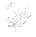
以下では、本発明の実施形態に係る押出成形用金型1について説明する。図1は、押出機50と、押出成形用金型1と、これらによって成形された長尺状樹脂部材55とを側方から視た模式図である。
Below, the metal mold|die 1 for extrusion molding which concerns on embodiment of this invention is demonstrated. FIG. 1 is a schematic view of an
なお、以下で説明する各図において、説明の便宜上、前と記載された矢印が指示する方向を前側、前方、又は手前側と称し、後と記載された矢印が指示する方向を後側、後方、又は奥側と称し、右と記載された矢印が指示する方向を右側と称し、左と記載された矢印が指示する方向を左側と称し、上と記載された矢印が指示する方向を上側又は上方と称し、下と記載された矢印が指示する方向を下側又は下方と称する。 In each of the drawings described below, for convenience of description, the direction indicated by the arrow described as front is referred to as the front side, the front, or the front side, and the direction indicated by the arrow described as rear is the rear side, the rear side. , Or the back side, the direction indicated by the arrow described as right is referred to as the right side, the direction indicated by the arrow described as left is referred to as the left side, and the direction indicated by the arrow described as above is the upper side or The direction indicated by the arrow described as "upper" and "lower" is referred to as "lower side" or "lower side".
押出成形用金型1では、押出機50のピストン51(ラムとも呼ばれる)によって順次、押し出されたペレット状の樹脂材料Mが、押出機50の可塑化シリンダー52及び押出成形用金型1の加熱領域HZによって加熱されて溶融されつつ、押出成形用金型1内に形成された樹脂通路18を通過する。樹脂通路18を通過する溶融樹脂は、押出成形用金型1の下流側に設けられた冷却領域CZによって冷却されて固化される。これにより、一続きの長尺状樹脂部材55が順次、形成される。この長尺状樹脂部材55は、樹脂通路18の樹脂通路出口19から順次排出された後、所望の長さに切断されることにより、押出成形品が形成される。
In the extrusion molding die 1, pelletized resin material M extruded sequentially by the piston 51 (also called ram) of the
[長尺状樹脂部材の形状]
図2は、長尺状樹脂部材55の断面斜視図である。本実施形態に係る押出成形用金型1では、前後方向に細長い長尺状樹脂部材55が形成される。長尺状樹脂部材55は、図2に示すように、長手方向に垂直な断面が略T字状となるように形成された、いわゆる異形押出成形品である。長尺状樹脂部材55は、下面56aが平坦状に形成された前後方向に延びる第1部分56と、該第1部分56の上面56bにおける左右方向中央部を前後方向に延びる第2部分57とを有し、これらが一体に形成されている。
[Shape of long resin member]
FIG. 2 is a cross-sectional perspective view of the
[押出成形用金型の構成]
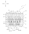
図3は、押出成形用金型1を上方から視た図である。また、図4は、押出成形用金型1を下方から視た図である。また、図5は、図3のV-V線における断面図であり、図6は、図3のVI-VI線における断面図である。
[Structure of extrusion mold]
FIG. 3 is a view of the extrusion molding die 1 as viewed from above. FIG. 4 is a view of the extrusion molding die 1 as viewed from below. 5 is a sectional view taken along line VV in FIG. 3, and FIG. 6 is a sectional view taken along line VI-VI in FIG.
図3から図6を参照して、押出成形用金型1は、上型3及び下型4を有する金型本体部2と、複数の型締めボルト27と、複数の面圧調整ボルト28と、複数の棒状部26とを有している。各棒状部26は、押しボルト29及びブレーキピン30を有している。
With reference to FIGS. 3 to 6, the extrusion molding die 1 includes a
[上型の構成]
上型3は、図5及び図6を参照して、上外型5及び上中型6を有している。
[Upper mold configuration]
The
上外型5は、上型3における上側の部分として設けられている。上外型5は、図5を参照して、前後方向に長く且つ上下方向に所定の厚みを有するブロック状に形成された上外型本体部11と、該上外型本体部11における後側の部分からさらに後側に延びる延出部12とを有し、これらが一体に形成されている。延出部12は、後側から視た形状が、上側に膨らむ半円弧状に形成されている。延出部12は、上型3及び下型4が互いに型締めされた状態において、詳しくは後述する下型4に形成された延出部32とともに、押出機連結部20を構成する。
The upper outer die 5 is provided as an upper portion of the
上外型本体部11の下側には、上中型6が嵌め込まれる凹部11aが形成されている。上中型6は、この凹部11aに嵌め込まれる。すなわち、上外型5及び上中型6は、入れ子構造となっている。
On the lower side of the upper
上外型本体部11には、複数の型締めボルト用ネジ孔(図示省略)と、複数の面圧調整ボルト用ネジ孔(図示省略)とが形成されている。各ネジ孔は、上外型本体部11を上下方向に貫通するネジ孔によって形成されている。
A plurality of screw holes for mold clamping bolts (not shown) and a plurality of screw holes for surface pressure adjusting bolts (not shown) are formed in the upper
型締めボルト用ネジ孔は、図3を参照して、型締めボルト27の位置に対応して35個、形成されている。すなわち、型締めボルト用ネジ孔は、上外型本体部11全体に亘って概ね均一的に(加熱領域HZ及び冷却領域CZの双方に亘って)形成されている。各型締めボルト用ネジ孔の内周面には、型締めボルト27が螺合可能な雌ネジが形成されている。
With reference to FIG. 3, 35 mold clamping bolt screw holes are formed corresponding to the positions of the
面圧調整ボルト用ネジ孔は、図3を参照して、面圧調整ボルト28に位置に対応して形成されている。すなわち、面圧調整ボルト用ネジ孔は、上外型本体部11の加熱領域HZと冷却領域CZの一部に形成されている。各面圧調整ボルト用ネジ孔の内周面には、面圧調整ボルト28が螺合可能な雌ネジが形成されている。
The screw holes for the surface pressure adjusting bolt are formed corresponding to the positions on the surface
また、図5を参照して、上外型本体部11の冷却領域CZには、複数の(本実施形態の場合、3つの)冷却水管16が形成されている。各冷却水管16は、上外型本体部11の冷却領域CZを左右方向に貫通する貫通孔によって形成されている。冷却水管16には、冷却水が流れる。これにより、押出成形用金型1の加熱領域HZから順次、搬送される溶融樹脂を冷却して固化することができる。
In addition, referring to FIG. 5, a plurality of (three in the present embodiment) cooling
また、図5を参照して、上外型本体部11の加熱領域HZには、例えば金型用のヒーターで構成された加熱機構9が設けられている。これにより、押出成形用金型1の加熱領域HZを流れる樹脂を溶融することができる。
Further, with reference to FIG. 5, in the heating region HZ of the upper outer mold
上中型6は、図5を参照して、上外型5に形成された凹部11aに嵌め込まれる入れ子である。上中型6は、前後方向に長く且つ上下方向に所定の厚みを有するブロック状に形成された上中型本体部21によって構成されている。
The upper middle mold 6 is a nest fitted in the
上中型本体部21には、複数の型締めボルト用貫通孔(図示省略)が形成されている。型締めボルト用貫通孔は、図3における型締めボルト27の位置に対応して形成されている。各型締めボルト用貫通孔23は、上中型6が上外型5に嵌め込まれた状態において、上方から視て、各型締めボルト用ネジ孔と重なる位置に形成されている。各型締めボルト用貫通孔は、型締めボルト27が挿通可能な大きさに形成されている。
A plurality of through holes (not shown) for mold clamping bolts are formed in the upper middle
[下型の構成]
下型4は、図5及び図6を参照して、下外型7及び下中型8を有している。下型4は、詳しくは後述する押圧部としての棒状部26が設けられる押圧部側金型として設けられている。
[Lower mold configuration]
The
下外型7は、下型4における下側の部分として設けられている。下外型7は、図5を参照して、前後方向に長く且つ上下方向に所定の厚みを有するブロック状に形成された下外型本体部31と、該下外型本体部31における後側の部分からさらに後側に延びる延出部32とを有し、これらが一体に形成されている。延出部32は、後側から視た形状が、下側に膨らむ半円弧状に形成されている。延出部32は、上述したように、上型3及び下型4が互いに型締めされた状態において、上外型5に形成された延出部12とともに、押出機連結部20を構成する。押出機連結部20の内側には、押出機50によって押し出された溶融樹脂が通過する押出機側樹脂通路(図示省略)が形成されている。
The lower outer die 7 is provided as a lower portion of the
下外型本体部31の上側には、下中型8が嵌め込まれる凹部31aが形成されている。下中型8は、この凹部31aに嵌め込まれる。すなわち、下外型7及び下中型8は、上外型5及び上中型6と同様、入れ子構造となっている。
A
下外型本体部31には、図4を参照して、複数の型締めボルト用ネジ孔33と、複数の押しボルト用ネジ孔34とが形成されている。各ネジ孔33,34は、下外型本体部31を上下方向に貫通するネジ孔によって形成されている。なお、押しボルト用ネジ孔34については、図4では図示を省略し、図5及び図6では図示している。
With reference to FIG. 4, a plurality of screw holes 33 for mold clamping bolts and a plurality of screw holes 34 for push bolts are formed in the lower outer mold
型締めボルト用ネジ孔33は、図4に示すように、上外型本体部11全体に亘って概ね均一的に(加熱領域HZ及び冷却領域CZの双方に亘って)形成されている。型締めボルト用ネジ孔33は、上型3及び下型4が互いに型締めされた状態において、上下方向から視て、上外型本体部11に形成された型締めボルト用ネジ孔が形成された位置に対応した位置に形成されている。各型締めボルト用ネジ孔の内周面には、型締めボルト27が螺合可能な雌ネジが形成されている。
As shown in FIG. 4, the mold clamping bolt screw holes 33 are formed substantially uniformly (over both the heating region HZ and the cooling region CZ) over the entire upper
押しボルト用ネジ孔34は、図4を参照して、押しボルト29の位置に対応して形成されている貫通孔であって、その内周面には、押しボルト29が螺合可能な雌ネジが形成されている。押しボルト用ネジ孔34は、冷却領域CZにおける樹脂通路出口19付近に形成されている。押しボルト用ネジ孔34は、本実施形態の場合、図6を参照して、左右方向に間隔を開けて4つ、形成されている。
Referring to FIG. 4, the push
また、図5を参照して、下外型本体部31の冷却領域CZには、複数の(本実施形態の場合、3つの)冷却水管36が形成されている。各冷却水管36は、下外型本体部31の冷却領域CZを左右方向に貫通する貫通孔によって形成されている。冷却水管36には、冷却水が流れる。これにより、押出成形用金型1の加熱領域HZから順次、搬送される溶融樹脂を冷却して固化することができる。
Further, with reference to FIG. 5, a plurality of (three in the present embodiment) cooling
また、図5を参照して、下外型本体部31の加熱領域HZには、上外型本体部11の場合と同様、金型用のヒーターで構成された加熱機構9が設けられている。これにより、押出成形用金型1の加熱領域HZを流れる樹脂を溶融することができる。
Further, referring to FIG. 5, in the heating region HZ of the lower outer die
下中型8は、図5を参照して、下外型7に形成された凹部31aに嵌め込まれる入れ子である。下中型8は、前後方向に長く且つ上下方向に所定の厚みを有するブロック状に形成された下中型本体部41によって構成されている。
Referring to FIG. 5, the lower
下中型本体部41には、複数の型締めボルト用貫通孔(図示省略)と、複数のブレーキピン用貫通孔44とが形成されている。各貫通孔は、下中型本体部41を上下方向に貫通している。
A plurality of through holes (not shown) for mold clamping bolts and a plurality of through
型締めボルト用貫通孔は、図3における型締めボルト27の位置に対応して形成されている。各型締めボルト用貫通孔は、上型3及び下型4が互いに型締めされた状態において、上下方向から視て、上外型本体部11に形成された型締めボルト用ネジ孔が形成された位置に対応した位置に形成されている。下中型本体部41に形成された型締めボルト用貫通孔は、上中型本体部21に形成された型締めボルト用貫通孔の場合と同様、型締めボルト27が挿通可能な大きさに形成されている。
The mold clamping bolt through holes are formed in correspondence with the positions of the
ブレーキピン用貫通孔44は、図4を参照して、押しボルト29の位置に対応して形成されている。すなわち、ブレーキピン用貫通孔44は、冷却領域CZにおける樹脂通路出口19付近に形成されている。ブレーキピン用貫通孔44は、本実施形態の場合、左右方向に間隔を開けて4つ、形成されている。図6を参照して、各ブレーキピン用貫通孔44は、上下方向から視て、対応する押しボルト用ネジ孔34と重なる位置に形成されている。各ブレーキピン用貫通孔44は、ブレーキピン30が挿通可能な大きさに形成されている。
The brake pin through
[樹脂通路の構成]
押出成形用金型1のPL面(具体的には上型3の下面及び下型4の上面)には、図5等を参照して、樹脂通路18が形成されている。樹脂通路18は、上外型5及び下外型7のそれぞれに形成された溝状の部分により構成された上流側樹脂通路18aと、上中型6に形成された溝状の部分と下中型8の上面とにより構成された下流側樹脂通路18b(図5及び図6参照)と、を有している。なお、図5は、押出成形用金型の所定位置における縦断面図であるため、上流側樹脂通路18aが押出機50側と連通していないようにも見えるが、実際には上流側樹脂通路18aは、押出機50側の樹脂通路と連通している。
[Construction of resin passage]
A
上流側樹脂通路18aは、上述した押出機側樹脂通路と、押出機側樹脂通路の下流端から分岐する4つの分岐路(図示省略)とを有している。
The
下流側樹脂通路18bは、図6を参照して、上型3及び下型4が互いに型締めされた状態における上中型6及び下中型8の間に4つ、形成されている。各下流側樹脂通路18bの上流端は、上流側樹脂通路18aの各分岐路の下流端に連通している。これにより、押出機50から押し出された溶融樹脂が押出機側樹脂通路を流れた後、各分岐路に分岐し、当該各分岐路を流れた溶融樹脂が、各分岐路の下流端と連通する各下流側樹脂通路18bを流れることとなる。
With reference to FIG. 6, four
4つの下流側樹脂通路18bは、互いに左右方向に間隔を開けて、前後方向に延びるように形成されている。各下流側樹脂通路18bは、その断面形状が、該下流側樹脂通路18bを通過しながら固化される長尺状樹脂部材55の断面が図2に示す略T字状となるような形状に形成されている。図6を参照して、押出成形用金型1の左右方向に並ぶ各下流側樹脂通路18bの下方には、各押しボルト29及び各ブレーキピン30が対応して配置されている。
The four
[各ボルト及びブレーキピンの構成]
型締めボルト27は、押出成形用金型1の型締めを行うためのボルトである。押出成形用金型1では、下型4に上型3が重ねられ、各型締めボルト用ネジ孔及び型締めボルト用貫通孔が上下方向に重なった状態で、型締めボルト27が螺合される。これにより、押出成形用金型1の型締めが行われる。
[Structure of each bolt and brake pin]
The
面圧調整ボルト28は、押出成形用金型1における上中型6と下中型8との間のPL面(金型分割面)の面圧を調整するためのボルトである。具体的には、面圧調整ボルト28は、下型4に上型3が重ねられた状態で、該面圧調整ボルト28の先端部が上中型6を押圧するように、面圧調整ボルト用ネジ孔14に螺合される。このとき、面圧調整ボルト28の締め込み度合を調整することにより、上中型6と下中型8との間のPL面の面圧を調整することができる。
The surface
押しボルト29は、押しボルト用ネジ孔34に螺合している。各押しボルト29は、対応して設けられたブレーキピン30を、その先端部分によって上方へ押圧するためのものである。各押しボルト29は、図5及び図6に示すように、樹脂通路18が延びる方向(すなわち、樹脂通路18を通過する長尺状樹脂部材55の進行方向)に対して垂直な方向となるように設けられている。
The
ブレーキピン30は、ブレーキピン用貫通孔44に挿通し、先端部分と反対側の部分(図6における下方側の部分)が押しボルト29の先端部分によって支持されている。各ブレーキピン30は、図5及び図6に示すように、押しボルト29の場合と同様、樹脂通路18を通過する長尺状樹脂部材55の進行方向に対して垂直な方向となるように設けられている。
The
ブレーキピン30は、その先端部分が下流側樹脂通路18bに露出しており、該先端部分によって下流側樹脂通路18bを通過する長尺状樹脂部材55の下面56a(図2参照)を押圧することができる。具体的には、押しボルト29の締め込み量を調整することにより、ブレーキピン30の長尺状樹脂部材55に対する押圧力を調整することができる。なお、このように長尺状樹脂部材55への押圧力を調整する理由については、長尺状樹脂部材55の成形過程とともに、以下で詳しく説明する。
The tip of the
[長尺状樹脂部材の成形過程]
図1から図6を参照して、本実施形態に係る押出成形用金型1では、型締めボルト27による上型3及び下型4の型締め、面圧調整ボルト28による上中型6と下中型8との間の面圧調整、押しボルト29の締め込み量(すなわち、樹脂通路18を通過する長尺状樹脂部材55に対する押しボルト29の押圧力)、その他の成形条件(金型温度等)が適切に設定された後、押出機50による樹脂材料Mの押し出しが行われる。ピストン51によって押し出された樹脂材料Mは、加熱されて溶融されつつ、上流側樹脂通路18a(すなわち、押出機側樹脂通路及び分岐路)を通過し、各分岐路の下流端から各下流側樹脂通路18bへ流れ込む。
[Molding process of long resin member]
With reference to FIGS. 1 to 6, in the extrusion molding die 1 according to the present embodiment, the
各下流側樹脂通路18bへ流れ込んだ溶融樹脂は、加熱領域HZに設けられた加熱機構9で加熱されつつ、冷却領域CZへ流れ込む。冷却領域CZにおける上流側の部分(表面固化領域)では、溶融樹脂が、冷却水管16,36を流れる冷却水によって冷却されることにより、下流側樹脂通路18bを流れる溶融樹脂の表面部分が固化される。そして、冷却領域CZにおける下流側の部分(完全固化領域)では、樹脂の内部についても固化される。これにより、樹脂の表面及び内部が固化された状態の長尺状樹脂部材55が生成される。このように生成された長尺状樹脂部材55は、樹脂通路出口19から金型外部へ順次、排出される。
The molten resin flowing into each
[ブレーキピンの機能について]
ところで、本実施形態に係る押出成形用金型1で生成される長尺状樹脂部材55は、いわゆる異形押出成形品であり、丸棒状或いは板状の押出成形品と比べて形状が複雑であるため、押出成形後の後加工が非常に困難である。すなわち、異形押出成形品では、押出成形された寸法及び外観性状が、そのまま製品の寸法及び外観性状となる。
[About the function of the brake pin]
By the way, the
上述のように良好な寸法精度及び外観品質を得るには、溶融樹脂が冷却されて固化する際の収縮を小さくすることが重要であり、そうするためには、表面固化領域(樹脂通路18における冷却領域CZの上流側の部分)において内部樹脂圧が大きくなるように保圧することが必要となる。 As described above, in order to obtain good dimensional accuracy and appearance quality, it is important to reduce shrinkage when the molten resin is cooled and solidified, and in order to do so, in the surface solidified region (in the resin passage 18). It is necessary to maintain the internal resin pressure so that the internal resin pressure becomes large in the upstream side portion of the cooling zone CZ).
この点につき、本実施形態に係る押出成形用金型1では、押しボルト29の締め込み量を調整することにより、下流側樹脂通路18bを通過する長尺状樹脂部材55に対するブレーキピン30の押圧力を調整することができる。例えば、図5及び図6を参照して、押しボルト29を締め込むと、下流側樹脂通路18bにおける樹脂通路出口19側の部分を通過する長尺状樹脂部材55に対するブレーキピン30の押圧力が大きくなる。そうなると、長尺状樹脂部材55が下流側樹脂通路18bにおける表面固化領域を通過する際の摩擦力が大きくなる。これにより、表面固化領域において内部樹脂圧が大きくなるように保圧することが可能となる。このように、押しボルト29の締め込み量を調整して、長尺状樹脂部材55に対するブレーキピン30の押圧力を調整することで、所望の寸法精度及び外観性状を有する長尺状樹脂部材55を生成することができる。
In this regard, in the extrusion molding die 1 according to the present embodiment, by adjusting the tightening amount of the
[実施例]
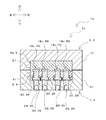
次に、本発明の実施例に係る押出成形用金型について説明する。図7は、実施例に係る押出成形用金型1aの断面図であって、図6に対応させて示す図である。
[Example]
Next, the extrusion molding die according to the embodiment of the present invention will be described. FIG. 7 is a cross-sectional view of the extrusion molding die 1a according to the embodiment, and is a view corresponding to FIG.
本実施例に係る押出成形用金型1aは、上述した実施形態に係る押出成形用金型1と比べて、金型本体部2aにおける上中型6aの構成が異なっている。具体的には、上記実施形態の上中型6は、該上中型6によって形成される長尺状樹脂部材55の横断面形状が略T字状となるよう、その横断面における下流側樹脂通路18b部分の形状が略T字状となっている。これに対して、本実施例の上中型6aは、その横断面における下流側樹脂通路18c部分の形状が横長の矩形状となっている。
The extrusion molding die 1a according to the present embodiment is different from the extrusion molding die 1 according to the above-described embodiment in the configuration of the upper
本実施例に係る押出成形用金型1aにも、上記実施形態の場合と同様、4つの下流側樹脂通路18cが形成されている。そして、本実施例でも、上記実施形態の場合と同様、各下流側樹脂通路18cに対応して、押しボルト29及びブレーキピン30が設けられている。以下では、押しボルト29によるブレーキピン30の押圧量(すなわち、ブレーキピン30による長尺状樹脂部材55の押圧力)を個別に調整することにより、各長尺状樹脂部材の単位時間当たりの長さを同程度にできるか否かを検証した。なお、以下では、図7を参照して、4つの下流側樹脂通路18cのそれぞれを、左側から順に、通路PA、通路PB、通路PC、及び通路PDと称する。また、通路PA,PB,PC,PDを通じて生成される成形品のそれぞれを、成形品SA,SB,SC,SDと称する。
Also in the extrusion molding die 1a according to the present embodiment, four
[評価方法]
可塑化シリンダーが約160度、金型の加熱領域が約140度の押出成形機にて、溶融した樹脂を4つの通路PA〜PDのそれぞれに通過させ、冷却水によって冷却して固化させた。これにより、幅が12mm、厚さが3mmの成形品SA〜SDを同時に成形した。
[Evaluation method]
The molten resin was passed through each of the four passages PA to PD using an extruder having a plasticizing cylinder of about 160 degrees and a mold heating area of about 140 degrees, and was cooled and solidified by cooling water. Thereby, molded products SA to SD having a width of 12 mm and a thickness of 3 mm were simultaneously molded.
その際、最初は、ブレーキピン30による成形品SA〜SDの押圧は行わず、成形品SA〜SDを4つの樹脂通路出口から同時に排出開始させ、一定時間経過したところで4本の成形品の同一箇所をマーキングし、その位置から成形品の先端までの長さを測定して、単位時間当たりの成形品長さのバラつきを確認した。その結果に基づき、押しボルト29にてブレーキピン30の押圧量を個別に調整して押出速度を変化させ、各成形品SA〜SDの単位時間当たりの長さが同程度になるか否かを検証した。なお、樹脂としては、粉末状の超高分子量ポリエチレン(UHMW−PE)を使用した。
At that time, at first, the molded products SA to SD are not pressed by the
[評価結果]
図8は、ブレーキピン30の押圧量を条件1から条件4の間で変化させた場合の、各成形品SA〜SDの単位時間当たりの長さを示す表である。図8における条件1では、ブレーキピン30による成形品SA〜SDの押圧は行っていない。条件2では、通路PB,PCのブレーキピン30のみを押圧した。条件3では、条件2に対して、通路PB,PCのブレーキピン30の押圧量をやや低減し且つ通路PA,PDのブレーキピン30を押圧した。条件4では、条件3に対して、通路PB,PCのブレーキピン30の押圧量を更に低減し且つ通路PA,PDのブレーキピン30の押圧量を更に大きくした。
[Evaluation results]
FIG. 8 is a table showing the length per unit time of each of the molded products SA to SD when the pressing amount of the
条件1では、成形品SB,SCの長さが成形品SA,SDの長さよりも長かったため、条件2では、通路PB,PCのブレーキピン30のみを押圧することにより、4つの成形品SA〜SD全ての長さが同じとなるように試みた。その結果、図8を参照して、通路PB,PCの押出速度が極端に低下してしまったため、成形品SB,SCの長さが成形品SA,SDの長さよりも極端に短くなってしまった。
In
条件3では、上述のように極端に短くなってしまった成形品SB,SCの長さを成形品SA,SDの長さに合わせるために、条件2に対して、通路PB,PCのブレーキピン30の押圧量をやや低減し且つ通路PA,PDのブレーキピン30を押圧した。その結果、図8に示すように、成形品SB,SCの長さが、成形品SA,SDの長さに近づいた。
Under the
条件4では、全成形品SA〜SDの長さを更に揃えるために、条件3に対して、通路PB,PCのブレーキピン30の押圧量を更に低減し且つ通路PA,PDのブレーキピン30の押圧量を更に大きくした。その結果、図8に示すように、全成形品SA〜SDの長さを概ね揃えることができた。
In
以上のように、本実施例に係る押出成形用金型1aの各通路PA〜PDに設けられたブレーキピン30の押圧量を個別に調整することにより、各成形品SA〜SDの単位時間当たりの長さを揃えることができることが確認できた。下流側樹脂通路の横断面形状が異なる押出成形用金型1についても、同様の効果が得られると考えられる。
As described above, by individually adjusting the pressing amount of the
なお、上述した条件4における各ブレーキピン30の押圧量を更に微調整することにより、各成形品SA〜SDの長さを更に揃えることも可能である。或いは、上述した条件2に対して、通路PB,PCのブレーキピン30の押圧量のみを調整することにより、各成形品SA〜SDの長さを更に揃えることも可能である。
The lengths of the molded products SA to SD can be further made uniform by further finely adjusting the pressing amount of each
[効果]
以上説明したように、上記実施形態に係る押出成形用金型1では、押出機50によって押し出された溶融樹脂が樹脂通路18を通過しつつ、該樹脂通路18の下流側に設けられた冷却領域CZによって冷却されて固化されることにより、長尺状樹脂部材55が形成される。このようにして形成された長尺状樹脂部材55は、樹脂通路出口19から順次流出され、所望の長さに切断されることにより、押出成形品が生成される。
[effect]
As described above, in the extrusion-
また、押出成形用金型1では、上型3及び下型4のうちの一方の金型(本実施形態の場場合、下型4)に設けられた押圧部(本実施形態の場合、棒状部26)を、樹脂通路18における樹脂通路出口19側の部分を通過する長尺状樹脂部材55に押圧することにより、冷却領域下流側(樹脂通路出口19側)を通過する長尺状樹脂部材55に対して摩擦力を付与できる。そうすると、当該樹脂部材が樹脂通路18を通過する際の摩擦力が大きくなるため、冷却領域CZの上流側を通過する樹脂部材(表面が固化されて内部が溶融状態となっている樹脂部材)の内部樹脂圧が大きくなる。これにより、内部樹脂が冷却されて固化される際に大きく収縮してしまうことを抑制できる。
In addition, in the extrusion molding die 1, the pressing portion (bar shape in the case of the present embodiment) provided in one of the
そして、押出成形用金型1によれば、長尺状樹脂部材55が樹脂通路18と通過する際の摩擦力を大きくするために樹脂通路を長くする必要がないため、金型の大型化及び高コスト化を抑制できる。更に、押出成形用金型1によれば、棒状部26が設けられた方の金型(本実施形態の場合、下型4)に対して該棒状部26を進退させることにより、長尺状樹脂部材55が樹脂通路18を通過する際の摩擦力を容易に調整することができる。
Further, according to the extrusion molding die 1, since it is not necessary to lengthen the resin passage in order to increase the frictional force when the
従って、押出成形用金型1では、所望の寸法精度及び外観性状を有する押出成形品を比較的容易に形成可能な押出成形用金型であって、コスト面及び設置スペースの観点において優れた押出成形用金型を提供できる。 Therefore, the extrusion molding die 1 is an extrusion molding die that can relatively easily form an extrusion molded article having desired dimensional accuracy and appearance, and is excellent in terms of cost and installation space. A molding die can be provided.
また、押出成形用金型1では、樹脂通路18の下流側を通過する長尺状樹脂部材55に摩擦力を付与するための押圧部を、全体的な形状が棒状に形成された棒状部26で構成することができるため、押圧部の構成を簡素化できる。
In addition, in the extrusion molding die 1, the pressing portion for applying a frictional force to the
また、押出成形用金型1では、押しボルト29を締め込んでブレーキピン30に向かって進出させたり、押しボルト29を緩めてブレーキピン30から後退させたりすることで、樹脂通路18を通過する長尺状樹脂部材55に対するブレーキピン30の押圧力を容易に調整することができる。
Further, in the extrusion molding die 1, the
また、押出成形用金型1では、棒状部26(押しボルト29及びブレーキピン30)を、樹脂通路18を通過する長尺状樹脂部材55の進行方向に対して垂直な方向となるように設けている。こうすると、棒状部26の押圧力を長尺状樹脂部材55の進行方向に対して垂直な方向に加えることができるため、棒状部26の押圧力が長尺状樹脂部材55の進行方向に分散することなく、該押圧力を効率的に長尺状樹脂部材55に伝達することができる。
Further, in the extrusion molding die 1, the rod-shaped portion 26 (the
また、押出成形用金型1では、ブレーキピン30が長尺状樹脂部材55における平坦状の部分(下面56a)を押圧しているため、長尺状樹脂部材55における所望の位置を確実に押圧することができる。そうすると、長尺状樹脂部材55に対するブレーキピン30の押圧力を安定化でき、ひいては長尺状樹脂部材55の寸法精度及び外観性状を安定化できる。
Further, in the extrusion molding die 1, since the
また、押出成形用金型1では、各棒状部26の押圧量(すなわち、各押しボルト29の締め込み量)を個別に調整することにより、複数の下流側樹脂通路18bのそれぞれを進行する長尺状樹脂部材55に対する摩擦力を個別に調整できる。これにより、各長尺状樹脂部材55の寸法精度及び外観性状を個別に調整することができる。
In addition, in the extrusion molding die 1, by individually adjusting the pressing amount of each rod-shaped portion 26 (that is, the tightening amount of each push bolt 29), the length of advancing in each of the plurality of
以上、本発明の実施形態について説明したが、本発明は上述の実施の形態に限られるものではなく、特許請求の範囲に記載した限りにおいて様々に変更して実施することができる。例えば、次のような変形例を実施してもよい。 Although the embodiments of the present invention have been described above, the present invention is not limited to the above-described embodiments, and various modifications can be made as long as they are set forth in the claims. For example, the following modified examples may be implemented.
(1)上述した実施形態では、棒状部26(押しボルト29及びブレーキピン30)を下型4側へ設けたが、これに限らず、上型側へ設けてもよい。
(1) In the above-described embodiment, the rod-shaped portion 26 (the
(2)上述した実施形態では、長尺状樹脂部材55を押圧する押圧部の構成を棒状に形成したが、これに限らず、その他の形状であってもよい。
(2) In the above-described embodiment, the configuration of the pressing portion that presses the
(3)上述した実施形態では、長尺状樹脂部材55を押圧する棒状部26を、押しボルト29及びブレーキピン30で構成したが、これに限らず、その他の構成であってもよい。例えば一例として、棒状部26を、押しボルト29のみで構成してもよい。この場合、押しボルト29の先端部で長尺状樹脂部材55を押圧する構成とすればよい。
(3) In the above-described embodiment, the rod-shaped
(4)上述した実施形態では、棒状部26を、長尺状樹脂部材55の進出方向に対して垂直な方向に沿って進退可能に設けたが、これに限らず、長尺状樹脂部材55の進出方向に対して交わる方向であれば、棒状部26をどのような方向に沿って進退させてもよい。
(4) In the above-described embodiment, the rod-shaped
(5)上述した実施形態では、ブレーキピン30によって長尺状樹脂部材55の平坦状の部分を押圧する構成としたが、これに限らず、ブレーキピン30によって長尺状樹脂部材55に摩擦力を付与できる部分であればどのような部分を押圧してもよい。具体的には、例えば一例として、ブレーキピン30によって長尺状樹脂部材55の角状の部分を押圧してもよい。
(5) In the above-described embodiment, the flat portion of the
(6)上述した実施形態では、本実施形態に係る押出成形用金型1を異形押出成形品に適用する例を挙げて説明したが、これに限らず、異形押出成形品以外の押出成形品(例えば、丸棒、或いは板状の成形品)に適用することもできる。 (6) In the above-described embodiment, an example in which the extrusion molding die 1 according to the present embodiment is applied to a profile extrusion molded product has been described, but the present invention is not limited to this, and an extrusion molded product other than the profile extrusion molded product. (For example, a round bar or a plate-shaped molded product) can be applied.
(7)上述した実施形態では、入れ子構造を有する上型及び下型を有する押出成形用金型を例に挙げて説明したが、これに限らず、本発明は、それぞれが一体に形成された上型及び下型を有する押出成形用金型に適用することもできる。 (7) In the embodiment described above, the extrusion mold having the upper mold and the lower mold having the nesting structure has been described as an example, but the present invention is not limited to this, and the present invention is formed integrally. It can also be applied to an extrusion molding die having an upper die and a lower die.
(8)上述した実施形態では、各樹脂通路18に対応して設けられた棒状部26が互いに独立して進退する構成を例に挙げて説明したが、これに限らず、例えば一例として、各樹脂通路に対応して設けられた棒状部を互いに固定又は一体化することにより、複数の棒状部を連動させて進退させてもよい。
(8) In the above-described embodiment, the configuration in which the rod-shaped
本発明は、長尺成形品を押出成形する際に用いられる押出成形用金型に広く適用できる。 INDUSTRIAL APPLICABILITY The present invention can be widely applied to extrusion molding dies used when extrusion molding a long molded product.
1 押出成形用金型
3 上型
4 下型
18 樹脂通路
19 樹脂通路出口
26 棒状部(押圧部)
50 押出機
55 長尺状樹脂部材
CZ 冷却領域
HZ 加熱領域
DESCRIPTION OF
50
Claims (6)
前記上型及び前記下型は、前記押出機によって押し出された前記溶融樹脂が加熱される領域である加熱領域と、前記加熱領域を通過した後の前記溶融樹脂が冷却される冷却領域と、を含み、
前記樹脂通路における前記樹脂通路出口側の部分において、前記上型及び前記下型のうちの一方の金型に対して進退可能に設けられ、前記樹脂通路における前記樹脂通路出口側の部分を通過する前記長尺状樹脂部材を、該長尺状樹脂部材の進行方向に交わる方向に向かって押圧する押圧部、を更に備えており、
前記一方の金型としての押圧部側金型には、貫通孔が形成され、
前記押圧部は、前記貫通孔に挿入される棒状部であり、
前記棒状部は、
先端部分が前記長尺状樹脂部材を押圧可能なように、前記貫通孔に対して進退するブレーキピンと、
前記貫通孔に形成された雌ネジ部に螺合する雄ネジ部が形成され、先端部分で前記ブレーキピンを前記長尺用樹脂部材側へ押圧する押しボルトと、
を有しており、
前記ブレーキピンは、その先端部分が、前記樹脂通路に露出して、前記樹脂通路を通過する前記長尺状樹脂部材に接触して当該長尺状樹脂部材を直接に押圧可能であることを特徴とする、押出成形用金型。 A resin passage having an upper die and a lower die, through which the molten resin extruded by the extruder in a state where the upper die and the lower die are clamped with each other is formed, and the molten resin is cooled, the resin passage A die for extrusion molding in which a long resin member is formed by flowing out from a resin passage outlet formed at the downstream end of
The upper mold and the lower mold have a heating region that is a region in which the molten resin extruded by the extruder is heated, and a cooling region in which the molten resin is cooled after passing through the heating region. Including,
A portion of the resin passage on the resin passage outlet side is provided so as to be able to move forward and backward with respect to one of the upper die and the lower die, and passes through a portion of the resin passage on the resin passage outlet side. The elongated resin member is further provided with a pressing portion that presses in a direction intersecting the traveling direction of the elongated resin member ,
A through hole is formed in the pressing part side mold as the one mold,
The pressing portion is a rod-shaped portion that is inserted into the through hole,
The rod-shaped portion,
A brake pin that advances and retreats with respect to the through hole so that the tip portion can press the elongated resin member,
A male screw portion that is screwed into the female screw portion formed in the through hole is formed, and a push bolt that presses the brake pin at the tip portion toward the long resin member side,
Has
The brake pin has a tip end portion exposed to the resin passage, and is capable of contacting the elongated resin member passing through the resin passage to directly press the elongated resin member. And the extrusion mold.
前記貫通孔には、前記押しボルトが螺合する押しボルト用ネジ孔と、前記押しボルト用ネジ孔に連通した状態で形成されて前記ブレーキピンが挿通されるブレーキピン用挿通孔とが設けられ、前記押しボルト用ネジ孔と前記ブレーキピン用挿通孔とが、上下方向において重なる位置に設けられていることを特徴とする、押出成形用金型。 The through hole is provided with a push bolt screw hole into which the push bolt is screwed, and a brake pin insertion hole that is formed in a state of communicating with the push bolt screw hole and into which the brake pin is inserted. The extrusion molding die is characterized in that the push bolt screw hole and the brake pin insertion hole are provided at positions overlapping in the vertical direction.
前記ブレーキピン用貫通孔に挿通された前記ブレーキピンは、その先端部分と反対側の部分が前記押しボルトの先端部分によって支持されていることを特徴とする、押出成形用金型。 The extrusion mold, wherein the brake pin inserted into the through hole for the brake pin has a portion opposite to the tip portion thereof supported by the tip portion of the push bolt.
前記棒状部は、前記長尺状樹脂部材の進行方向に対して垂直な方向に沿って進退可能に設けられていることを特徴とする、押出成形用金型。 The extrusion mold according to any one of claims 1 to 3 ,
The extrusion-molding die is characterized in that the rod-shaped portion is provided so as to be capable of advancing and retracting along a direction perpendicular to the traveling direction of the elongated resin member.
前記押圧部における前記長尺状樹脂部材を押圧する部分は、前記長尺状樹脂部材における平坦状の部分を押圧することを特長とする、押出成形用金型。 The extrusion mold according to any one of claims 1 to 4,
An extrusion molding die, wherein a portion of the pressing portion that presses the long resin member presses a flat portion of the long resin member.
複数の前記樹脂通路が形成され、
それぞれが、複数の前記樹脂通路のそれぞれに対応して設けられる複数の前記押圧部を更に備えていることを特徴とする、押出成形用金型。 The extrusion mold according to any one of claims 1 to 5,
A plurality of the resin passages are formed,
The extrusion molding die, further comprising a plurality of pressing portions provided corresponding to the plurality of resin passages, respectively.
Applications Claiming Priority (2)
| Application Number | Priority Date | Filing Date | Title |
|---|---|---|---|
| JP2015130188 | 2015-06-29 | ||
| JP2015130188 | 2015-06-29 |
Publications (2)
| Publication Number | Publication Date |
|---|---|
| JP2017013501A JP2017013501A (en) | 2017-01-19 |
| JP6710593B2 true JP6710593B2 (en) | 2020-06-17 |
Family
ID=57827620
Family Applications (1)
| Application Number | Title | Priority Date | Filing Date |
|---|---|---|---|
| JP2016125209A Active JP6710593B2 (en) | 2015-06-29 | 2016-06-24 | Extrusion mold |
Country Status (1)
| Country | Link |
|---|---|
| JP (1) | JP6710593B2 (en) |
Families Citing this family (1)
| Publication number | Priority date | Publication date | Assignee | Title |
|---|---|---|---|---|
| JP7130585B2 (en) * | 2018-03-27 | 2022-09-05 | 三ツ星ベルト株式会社 | Extrusion mold |
Family Cites Families (7)
| Publication number | Priority date | Publication date | Assignee | Title |
|---|---|---|---|---|
| JPS5295768A (en) * | 1976-02-09 | 1977-08-11 | Mitsubishi Plastics Ind | Method of extrusion molding thermoplastic synthetic resin film |
| JPS5490358A (en) * | 1977-12-28 | 1979-07-18 | Unitika Ltd | Production of polyvinyl alcohol film for simultaneously biaxially oriented film with improved thickness precision |
| JPH045017A (en) * | 1990-04-24 | 1992-01-09 | Mitsubishi Plastics Ind Ltd | Solidifying extrusion forming device |
| JPH04126733A (en) * | 1990-09-17 | 1992-04-27 | Furukawa Electric Co Ltd:The | Production of crosslinked and expanded material |
| JP2968576B2 (en) * | 1990-11-14 | 1999-10-25 | 三菱樹脂株式会社 | Solidification extrusion equipment |
| JP5087621B2 (en) * | 2006-07-21 | 2012-12-05 | クワドラント エーペーペー アクチェンゲゼルシャフト | Ultra high molecular weight polyethylene panel and manufacturing method thereof |
| US7758796B2 (en) * | 2006-07-21 | 2010-07-20 | Quadrant Epp Ag | Production of UHMWPE sheet materials |
-
2016
- 2016-06-24 JP JP2016125209A patent/JP6710593B2/en active Active
Also Published As
| Publication number | Publication date |
|---|---|
| JP2017013501A (en) | 2017-01-19 |
Similar Documents
| Publication | Publication Date | Title |
|---|---|---|
| JP5841246B2 (en) | Alternative pressure control for low constant pressure injection molding equipment | |
| JP5824143B2 (en) | Equipment for injection molding at low constant pressure | |
| JPH03500400A (en) | Improvements in methods and apparatus for continuous forming of extrudates | |
| US7503992B2 (en) | Flashless welding method and apparatus | |
| US3680997A (en) | Extrusion strip die for thermoplastic sheet | |
| TW201429669A (en) | Reduced size runner for an injection mold system | |
| KR20180013974A (en) | A tire strip extrusion apparatus for producing treads and / or side strips for tires, and a method for producing a tread or side strip of a tire | |
| JP6710593B2 (en) | Extrusion mold | |
| CA2385564C (en) | Improved mixer apparatus and method for injection molding machines | |
| CN105398021B (en) | A kind of exhibition stream method of the full meshing gear of melt extrusion pressure-driven | |
| JP6489691B2 (en) | Extrusion mold | |
| US9849641B2 (en) | Method and apparatus for helical cutting of a tubular film | |
| CN205058487U (en) | Skew T injection mold | |
| JP2006231805A (en) | Extrusion molding method and extrusion molding apparatus | |
| JP7130585B2 (en) | Extrusion mold | |
| AT412771B (en) | EXTRUSION TOOL FOR A PLASTIC MELT | |
| JP2013103451A (en) | Method of manufacturing thermoplastic resin molded body | |
| US6607688B1 (en) | Lattice gate for drop gate injection molding | |
| JPS59114027A (en) | Extrusion molding die | |
| WO2017082934A1 (en) | Impingement surfaces | |
| CA1066865A (en) | Molding machine for making uhmw polyethylene or hollow tubing | |
| JP2013082205A (en) | Thermoplastic resin molded article manufacturing method | |
| US20040175537A1 (en) | Polymer component, apparatus and method | |
| JPH071549A (en) | Metal mold for extrusion molding of thick wall synthetic resin plate | |
| KR200352652Y1 (en) | Metallic mould |
Legal Events
| Date | Code | Title | Description |
|---|---|---|---|
| A621 | Written request for application examination |
Free format text: JAPANESE INTERMEDIATE CODE: A621 Effective date: 20181213 |
|
| RD02 | Notification of acceptance of power of attorney |
Free format text: JAPANESE INTERMEDIATE CODE: A7422 Effective date: 20191107 |
|
| A977 | Report on retrieval |
Free format text: JAPANESE INTERMEDIATE CODE: A971007 Effective date: 20191120 |
|
| A131 | Notification of reasons for refusal |
Free format text: JAPANESE INTERMEDIATE CODE: A131 Effective date: 20191126 |
|
| A521 | Request for written amendment filed |
Free format text: JAPANESE INTERMEDIATE CODE: A523 Effective date: 20200121 |
|
| TRDD | Decision of grant or rejection written | ||
| A01 | Written decision to grant a patent or to grant a registration (utility model) |
Free format text: JAPANESE INTERMEDIATE CODE: A01 Effective date: 20200526 |
|
| A61 | First payment of annual fees (during grant procedure) |
Free format text: JAPANESE INTERMEDIATE CODE: A61 Effective date: 20200527 |
|
| R150 | Certificate of patent or registration of utility model |
Ref document number: 6710593 Country of ref document: JP Free format text: JAPANESE INTERMEDIATE CODE: R150 |
|
| R250 | Receipt of annual fees |
Free format text: JAPANESE INTERMEDIATE CODE: R250 |