JP6710039B2 - Planning device, planning method and program - Google Patents
Planning device, planning method and program Download PDFInfo
- Publication number
- JP6710039B2 JP6710039B2 JP2015211898A JP2015211898A JP6710039B2 JP 6710039 B2 JP6710039 B2 JP 6710039B2 JP 2015211898 A JP2015211898 A JP 2015211898A JP 2015211898 A JP2015211898 A JP 2015211898A JP 6710039 B2 JP6710039 B2 JP 6710039B2
- Authority
- JP
- Japan
- Prior art keywords
- turbine
- remaining life
- parts
- operation plan
- life
- Prior art date
- Legal status (The legal status is an assumption and is not a legal conclusion. Google has not performed a legal analysis and makes no representation as to the accuracy of the status listed.)
- Active
Links
Images


Classifications
-
- F—MECHANICAL ENGINEERING; LIGHTING; HEATING; WEAPONS; BLASTING
- F01—MACHINES OR ENGINES IN GENERAL; ENGINE PLANTS IN GENERAL; STEAM ENGINES
- F01D—NON-POSITIVE DISPLACEMENT MACHINES OR ENGINES, e.g. STEAM TURBINES
- F01D25/00—Component parts, details, or accessories, not provided for in, or of interest apart from, other groups
- F01D25/28—Supporting or mounting arrangements, e.g. for turbine casing
- F01D25/285—Temporary support structures, e.g. for testing, assembling, installing, repairing; Assembly methods using such structures
-
- G—PHYSICS
- G01—MEASURING; TESTING
- G01M—TESTING STATIC OR DYNAMIC BALANCE OF MACHINES OR STRUCTURES; TESTING OF STRUCTURES OR APPARATUS, NOT OTHERWISE PROVIDED FOR
- G01M15/00—Testing of engines
- G01M15/14—Testing gas-turbine engines or jet-propulsion engines
-
- F—MECHANICAL ENGINEERING; LIGHTING; HEATING; WEAPONS; BLASTING
- F01—MACHINES OR ENGINES IN GENERAL; ENGINE PLANTS IN GENERAL; STEAM ENGINES
- F01D—NON-POSITIVE DISPLACEMENT MACHINES OR ENGINES, e.g. STEAM TURBINES
- F01D21/00—Shutting-down of machines or engines, e.g. in emergency; Regulating, controlling, or safety means not otherwise provided for
- F01D21/003—Arrangements for testing or measuring
-
- F—MECHANICAL ENGINEERING; LIGHTING; HEATING; WEAPONS; BLASTING
- F01—MACHINES OR ENGINES IN GENERAL; ENGINE PLANTS IN GENERAL; STEAM ENGINES
- F01D—NON-POSITIVE DISPLACEMENT MACHINES OR ENGINES, e.g. STEAM TURBINES
- F01D25/00—Component parts, details, or accessories, not provided for in, or of interest apart from, other groups
-
- F—MECHANICAL ENGINEERING; LIGHTING; HEATING; WEAPONS; BLASTING
- F01—MACHINES OR ENGINES IN GENERAL; ENGINE PLANTS IN GENERAL; STEAM ENGINES
- F01L—CYCLICALLY OPERATING VALVES FOR MACHINES OR ENGINES
- F01L25/00—Drive, or adjustment during the operation, or distribution or expansion valves by non-mechanical means
-
- F—MECHANICAL ENGINEERING; LIGHTING; HEATING; WEAPONS; BLASTING
- F02—COMBUSTION ENGINES; HOT-GAS OR COMBUSTION-PRODUCT ENGINE PLANTS
- F02C—GAS-TURBINE PLANTS; AIR INTAKES FOR JET-PROPULSION PLANTS; CONTROLLING FUEL SUPPLY IN AIR-BREATHING JET-PROPULSION PLANTS
- F02C7/00—Features, components parts, details or accessories, not provided for in, or of interest apart form groups F02C1/00 - F02C6/00; Air intakes for jet-propulsion plants
-
- G—PHYSICS
- G01—MEASURING; TESTING
- G01M—TESTING STATIC OR DYNAMIC BALANCE OF MACHINES OR STRUCTURES; TESTING OF STRUCTURES OR APPARATUS, NOT OTHERWISE PROVIDED FOR
- G01M15/00—Testing of engines
- G01M15/02—Details or accessories of testing apparatus
-
- G—PHYSICS
- G01—MEASURING; TESTING
- G01M—TESTING STATIC OR DYNAMIC BALANCE OF MACHINES OR STRUCTURES; TESTING OF STRUCTURES OR APPARATUS, NOT OTHERWISE PROVIDED FOR
- G01M7/00—Vibration-testing of structures; Shock-testing of structures
- G01M7/02—Vibration-testing by means of a shake table
- G01M7/025—Measuring arrangements
-
- F—MECHANICAL ENGINEERING; LIGHTING; HEATING; WEAPONS; BLASTING
- F05—INDEXING SCHEMES RELATING TO ENGINES OR PUMPS IN VARIOUS SUBCLASSES OF CLASSES F01-F04
- F05D—INDEXING SCHEME FOR ASPECTS RELATING TO NON-POSITIVE-DISPLACEMENT MACHINES OR ENGINES, GAS-TURBINES OR JET-PROPULSION PLANTS
- F05D2260/00—Function
- F05D2260/80—Diagnostics
-
- F—MECHANICAL ENGINEERING; LIGHTING; HEATING; WEAPONS; BLASTING
- F05—INDEXING SCHEMES RELATING TO ENGINES OR PUMPS IN VARIOUS SUBCLASSES OF CLASSES F01-F04
- F05D—INDEXING SCHEME FOR ASPECTS RELATING TO NON-POSITIVE-DISPLACEMENT MACHINES OR ENGINES, GAS-TURBINES OR JET-PROPULSION PLANTS
- F05D2270/00—Control
- F05D2270/01—Purpose of the control system
- F05D2270/11—Purpose of the control system to prolong engine life
Landscapes
- Engineering & Computer Science (AREA)
- Mechanical Engineering (AREA)
- General Engineering & Computer Science (AREA)
- Chemical & Material Sciences (AREA)
- Combustion & Propulsion (AREA)
- Physics & Mathematics (AREA)
- General Physics & Mathematics (AREA)
- Testing Of Devices, Machine Parts, Or Other Structures Thereof (AREA)
- Management, Administration, Business Operations System, And Electronic Commerce (AREA)
- Control Or Security For Electrophotography (AREA)
Description
本発明は、タービンの部品の運用計画を生成する計画装置、計画方法およびプログラムに関する。 The present invention relates to a planning device, a planning method and a program for generating an operation plan for turbine parts.
特許文献1には、ガスタービン高温部品のローテーション計画において、高温部品の余寿命が次回予定運転期間に満たない場合に、自主点検タイミングの時期を変更することで、高温部品の廃却時における余寿命を最小化する技術が開示されている。
In
しかしながら、プラントによっては自主点検を実施せずに定期点検のみを実施することがある。この場合、特許文献1に開示された技術によっては、部品の余寿命を最小化することができない可能性がある。
本発明の目的は、自主点検タイミングの変更によらずにタービンの部品を効率よく運用する計画装置、計画方法およびプログラムを提供することにある。
However, depending on the plant, only the periodic inspection may be performed without performing the voluntary inspection. In this case, the technique disclosed in
An object of the present invention is to provide a planning device, a planning method, and a program for efficiently operating parts of a turbine without changing the voluntary inspection timing.
本発明の第1の態様によれば、計画装置は、タービンに組み込み可能な複数の部品の余寿命を特定する余寿命特定部と、前記タービンの点検時期に、特定された前記複数の部品の余寿命に基づいて、前記複数の部品の中から前記余寿命が次回の点検時期までのインターバル未満となる部品を特定し、特定した前記部品のうち前記余寿命の差が許容誤差値となる組み合わせに係る部品を前記タービンに組み込み、特定した前記部品のうち前記組み合わせ以外の部品を倉庫に格納することを示す運用計画を生成する運用計画生成部とを備える。 According to the first aspect of the present invention, the planning device includes a remaining life specifying unit that specifies a remaining life of a plurality of components that can be incorporated in the turbine, and a plurality of the specified components at the inspection time of the turbine . A combination in which, based on the remaining life, a part whose remaining life is less than the interval until the next inspection time is specified from the plurality of parts , and the difference in the remaining life of the specified parts is an allowable error value. see write assembled parts to the turbine of the, and a production plan generation unit for generating a management plan that indicates the storage of parts other than the combination of the components identified in the warehouse.
本発明の第2の態様によれば、第1の態様に係る計画装置は、前記運用計画生成部が、特定された前記余寿命に基づいて、同一のタイミングにおいて、同一の前記タービンに組み込まれた複数の部品の余寿命が前記許容誤差値以内になるように、前記運用計画を生成する。 According to the second aspect of the present invention, in the planning device according to the first aspect, the operation plan generation unit is incorporated in the same turbine at the same timing based on the specified remaining life. The operation plan is generated so that the remaining lives of the plurality of parts are within the allowable error value.
本発明の第3の態様によれば、第2の態様に係る計画装置は、前記部品の余寿命と前記インターバルとに基づいて、前記タービンに組み込むと計画されたすべての部品が、次の点検時期において許容誤差値以内となる温度となるように、組み込み対象の前記タービンの負荷を決定する運転計画生成部とを備える。 According to a third aspect of the present invention, in the planning device according to the second aspect , based on the remaining life of the component and the interval, all components planned to be installed in the turbine are checked for the next inspection. And an operation plan generation unit that determines the load of the turbine to be installed so that the temperature is within the allowable error value at the time .
本発明の第4の態様によれば、第2または第3の態様に係る計画装置は、前記運用計画生成部が、第1部品の余寿命および第2部品の余寿命が定期点検のインターバルより短く、かつ前記第1の部品の余寿命と前記第2部品の余寿命との差が許容誤差値以内である場合に、前記第1部品と前記第2部品とを同一の前記タービンに組み込むことを示す前記運用計画を生成する。 According to the fourth aspect of the present invention, in the planning apparatus according to the second or third aspect, the operation plan generating unit determines the remaining life of the first component and the remaining life of the second component from the intervals of regular inspection. Incorporating the first part and the second part in the same turbine when the difference is short and the difference between the remaining life of the first part and the remaining life of the second part is within an allowable error value. Is generated.
本発明の第5の態様によれば、第1の態様に係る計画装置は、前記運用計画生成部が、特定された前記余寿命に基づいて、前記タービンの点検時期において、前記タービンに組み込まれた前記部品の余寿命が前記許容誤差値以内になるように、前記運用計画を生成する。 According to a fifth aspect of the present invention, in the planning apparatus according to the first aspect, the operation plan generation unit is incorporated in the turbine at an inspection time of the turbine based on the specified remaining life. The operation plan is generated so that the remaining life of the component is within the allowable error value.
本発明の第6の態様によれば、第5の態様に係る計画装置は、複数のタービンについて、前記定期点検のインターバルの間における前記部品の消費寿命を算出する消費寿命算出部をさらに備え、前記運用計画生成部が、各前記タービンへの組み込み回数と消費寿命の積の総和と、前記部品の余寿命との差が所定値以内となるように、前記タービンへの組み込み回数を示す前記運用計画を生成する。 According to a sixth aspect of the present invention, the planning apparatus according to the fifth aspect further includes a consumption life calculation unit that calculates the consumption life of the component during the regular inspection interval for a plurality of turbines, The operation plan generation unit, the operation indicating the number of times of incorporation into the turbine, so that the difference between the sum of the product of the number of times of incorporation into each turbine and the consumption life and the remaining life of the component is within a predetermined value. Generate a plan.
本発明の第7の態様によれば、計画方法は、計画装置の余寿命特定部が、タービンに組み込み可能な複数の部品の余寿命を特定するステップと、前記計画装置の運用計画生成部が、前記タービンの点検時期に、特定された前記複数の部品の余寿命に基づいて、前記複数の部品の中から前記余寿命が次回の点検時期までのインターバル未満となる部品を特定し、特定した前記部品のうち前記余寿命の差が許容誤差値となる組み合わせに係る部品を前記タービンに組み込み、特定した前記部品のうち前記組み合わせ以外の部品を倉庫に格納することを示す運用計画を生成するステップとを有する。
According to a seventh aspect of the present invention, in the planning method, the remaining life specifying unit of the planning device specifies the remaining life of a plurality of components that can be installed in the turbine, and the operation plan generating unit of the planning device. , At the inspection time of the turbine, based on the remaining life of the plurality of specified parts, the parts having the remaining life less than the interval until the next inspection time are specified and specified from the plurality of parts. Step of generating an operation plan indicating that a part related to a combination in which the difference in remaining life is an allowable error value is installed in the turbine, and parts other than the combination among the specified parts are stored in a warehouse Have and.
本発明の第8の態様によれば、プログラムは、コンピュータを、タービンに組み込み可能な複数の部品の余寿命を特定する余寿命特定部、前記タービンの点検時期に、特定された前記複数の部品の余寿命に基づいて、前記複数の部品の中から前記余寿命が次回の点検時期までのインターバル未満となる部品を特定し、特定した前記部品のうち前記余寿命の差が許容誤差値となる組み合わせに係る部品を前記タービンに組み込み、特定した前記部品のうち前記組み合わせ以外の部品を倉庫に格納することを示す運用計画を生成する運用計画生成部として機能させる。 According to an eighth aspect of the present invention, a program causes a computer to specify a remaining life of a plurality of parts that can be installed in a turbine , a remaining life specifying part, and the plurality of parts specified at the time of inspection of the turbine. On the basis of the remaining life, the parts whose remaining life is less than the interval to the next inspection time are specified from the plurality of parts , and the difference in the remaining life among the specified parts becomes the allowable error value. see write set of parts according to the combination to the turbine to function as the operation plan generation unit for generating a management plan that indicates the storage of parts other than the combination of the components identified in the warehouse.
上記態様のうち少なくとも1つの態様によれば、計画装置は、部品の余寿命が許容誤差値以内になるように運用計画を生成する。これにより、計画装置は、自主点検タイミングの変更によらずにタービンの部品を効率よく運用することができる。 According to at least one of the above aspects, the planning apparatus generates the operation plan such that the remaining life of the component is within the allowable error value. As a result, the planning device can efficiently operate the turbine components without changing the self-checking timing.
《第1の実施形態》
以下、図面を参照しながら第1の実施形態について詳しく説明する。
図1は、第1の実施形態に係る計画装置の構成を示す概略ブロック図である。
第1の実施形態に係る計画装置1は、タービンの部品の運用計画を生成する。第1の実施形態に係る部品の運用計画は、点検中のタービンに取り付けられている部品および倉庫に格納されている部品の各部品について、次回の運転のためにタービンに取り付けるか倉庫に格納するかを示す情報である。
第1の実施形態に係る計画装置1は、データ収集部101、ヒートバランス算出部102、消費寿命算出部103、余寿命特定部104、余寿命記憶部105、点検時期記憶部106、運用計画生成部107、発電電力量予測部108、運転計画生成部109、出力部110を備える。
<<First Embodiment>>
Hereinafter, the first embodiment will be described in detail with reference to the drawings.
FIG. 1 is a schematic block diagram showing the configuration of the planning device according to the first embodiment.
The
The
データ収集部101は、顧客が所有する発電プラントからリアルタイムにタービンの運転データを収集する。具体的には、データ収集部101は、タービンに設けられたセンサから所定の収集周期(例えば、5分)ごとに、運転データを収集する。収集周期は、監視の即時性が失われない程度に短い周期である。運転データの例としては、流量、圧力、温度、振動、およびその他の状態量が挙げられる。
The
ヒートバランス算出部102は、データ収集部101が収集した運転データに基づいて、タービンのヒートバランスを算出する。ヒートバランスとは、タービンに取り付けられた各部品それぞれにおける温度、圧力、エンタルピ、流量、およびその他の状態量である。ヒートバランス算出部102は、運転データに基づくシミュレーションによりヒートバランスを算出する。ヒートバランス算出のためのシミュレーションの手法の例としては、FEM(Finite Element Method)およびCFD(Computational Fluid Dynamics)が挙げられる。
The heat
消費寿命算出部103は、ヒートバランス算出部102が算出したヒートバランスに基づいて、直近の収集周期における各部品の消費寿命を算出する。本実施形態では、消費寿命は等価運転時間によって表される。
The consumption
余寿命特定部104は、余寿命記憶部105が記憶する余寿命から、消費寿命算出部103が算出する消費寿命を減算することで、部品の余寿命を特定する。
余寿命記憶部105は、各部品の余寿命を記憶する。部品の余寿命は、部品ごとに定められる設計寿命から消費寿命算出部103が算出する消費寿命を逐次減算することで得られる。
The remaining
The remaining
点検時期記憶部106は、各発電プラントに設けられる各タービンの点検時期を示す日付を記憶する。タービンの点検は、所定のインターバルごとに実行される。
運用計画生成部107は、タービンの点検時期に、そのタービンに取り付けられている部品および倉庫に格納されている部品の各部品について、運用計画を生成する。
発電電力量予測部108は、ネットワークを介して市場電力需要情報を取得し、管理対象の各発電プラントが発電すべき電力量を予測する。
運転計画生成部109は、タービンの負荷を示す運転計画を生成する。
出力部110は、運用計画生成部107が生成した運用計画および運転計画生成部109が生成した運転計画を出力する。運用計画および運転計画の出力形式の例としては、ディスプレイへの表示、記憶媒体への記録、およびシートへの印刷が挙げられる。
The inspection
The operation
The generated power
The operation
The
ここで、本実施形態に係る計画装置1の動作について説明する。
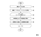
図2は、第1の実施形態に係る計画装置の収集周期ごとの動作を示すフローチャートである。
計画装置1は、収集周期ごとに、以下に示す処理を実行する。
まずデータ収集部101は、タービンに設けられたセンサからタービンの運転データを収集する(ステップS1)。次に、ヒートバランス算出部102は、収集された運転データを入力としてタービンのヒートバランスを算出する(ステップS2)。
Here, the operation of the
FIG. 2 is a flowchart showing the operation of the planning apparatus according to the first embodiment for each collection cycle.
The
First, the
次に、計画装置1は、タービンに組み込まれた部品を1つずつ選択し、選択された部品について、それぞれ以下に示すステップS4からステップS5の処理を実行する(ステップS3)。
まず、消費寿命算出部103は、ヒートバランス算出部102が算出したヒートバランスを用いて、選択された部品の直近の収集周期の間における消費寿命を算出する(ステップS4)。次に、余寿命特定部104は、余寿命記憶部105が選択された部品に関連付けて記憶する余寿命から、算出した消費寿命を減算する(ステップS5)。これにより、余寿命特定部104は、余寿命記憶部105が記憶する余寿命を更新する。
Next, the
First, the consumption
計画装置1は、上記ステップS1からステップS5の処理を収集周期ごとに実行することで、余寿命記憶部105が記憶する各部品の余寿命を最新の状態に保つことができる。
The
ここで、本実施形態に係る計画装置による運用計画の生成処理について説明する。
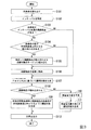
図3は、第1の実施形態に係る計画装置による運用計画の生成処理を示すフローチャートである。
現在の日付があるタービンの点検期間である場合、計画装置1は、運用計画の生成処理を開始する。まず、運用計画生成部107は、点検対象のタービンに組み込まれた各部品と、倉庫に格納されている各部品に関連付けられた余寿命を、余寿命記憶部105から読み出す(ステップS101)。次に、運用計画生成部107は、点検時期記憶部106を参照し、次回の点検時期までのインターバルを特定する(ステップS102)。次に、運用計画生成部107は、読み出した余寿命が、点検対象のタービンの次回の点検期間までのインターバル未満となる部品があるか否かを判定する(ステップS103)。以下、余寿命が点検期間までのインターバル未満である部品を、高齢部品とよぶ。例えば、点検期間のインターバルが18000時間である場合、余寿命が18000時間未満の部品は、高齢部品である。
Here, a process of generating an operation plan by the planning apparatus according to this embodiment will be described.
FIG. 3 is a flowchart showing a process of generating an operation plan by the planning device according to the first embodiment.
When it is the turbine inspection period with the current date, the
高齢部品がない場合(ステップS103:NO)、運用計画生成部107は、所定のアルゴリズムに従って、各部品の運用計画を生成する(ステップS107)。例えば、運用計画生成部107は、各部品の余寿命のばらつきが最小になるように各部品の運用計画を生成することができる。また例えば、運用計画生成部107は、予め定めた部品グループをローテーションするように運用計画を生成することができる。
When there is no aged part (step S103: NO), the operation
他方、高齢部品がある場合(ステップS103:YES)、運用計画生成部107は、余寿命の差が許容誤差値(例えば、100時間)以内となる高齢部品の組み合わせが存在するか否かを判定する(ステップS104)。高齢部品の組み合わせは、2つの高齢部品の組み合わせに限られず、3つ以上の高齢部品の組み合わせであってよい。例えば、余寿命9950時間の第1部品と余寿命10000時間の第2部品と、余寿命10030時間の第3部品の組み合わせは、余寿命の差が許容誤差値である100時間以内となる高齢部品の組み合わせである。
On the other hand, when there is an aged part (step S103: YES), the operation
余寿命の差が許容誤差値以内となる高齢部品の組み合わせが存在しない場合(ステップS104:NO)、運用計画生成部107は、各高齢部品について、倉庫に格納することを示す運用計画を生成する(ステップS106)。次に、運用計画生成部107は、運用計画が未定である残りの部品について、所定のアルゴリズムに従って運用計画を生成する(ステップS107)。これにより、運用計画生成部107は、次回の点検期間までに寿命に至る部品がないように、運用計画を生成することができる。
When there is no combination of aged parts whose residual life difference is within the allowable error value (step S104: NO), the operation
他方、余寿命の差が許容誤差値以内となる高齢部品の組み合わせが存在する場合(ステップS104:YES)、運用計画生成部107は、特定した組み合わせに係る高齢部品について、点検対象のタービンに組み込むことを示す運用計画を生成する(ステップS105)。具体的には、運用計画生成部107は、第1部品および第2部品の余寿命が定期点検のインターバルより短く、かつ第1の部品の余寿命と第2部品の余寿命との差が許容誤差値以内である場合に、第1部品と第2部品とを同一のタービンに組み込むことを示す運用計画を生成する。
次に、運用計画生成部107は、運用計画が未定である残りの高齢部品について、倉庫に格納することを示す運用計画を生成する(ステップS106)。次に、運用計画生成部107は、運用計画が未定である残りの部品について、所定のアルゴリズムに従って運用計画を生成する(ステップS107)。これにより、運用計画生成部107は、点検対象のタービンの運用によって、組み合わせに係る高齢部品が略同時に寿命に至るように、運用計画を生成することができる。
On the other hand, when there is a combination of aged parts for which the difference in remaining life is within the allowable error value (step S104: YES), the operation
Next, the operation
運用計画生成部107が運用計画を生成すると、運転計画生成部109は、生成された運用計画を参照し、点検対象のタービンに高齢部品が組み込まれるか否かを判定する(ステップS108)。点検対象のタービンに高齢部品が組み込まれる場合(ステップS108:YES)、運転計画生成部109は、次回の定期点検時に高齢部品の余寿命が許容誤差値以内になるように運転計画を生成する(ステップS109)。具体的には、運転計画生成部109は、以下の手順で運転計画を生成する。まず運転計画生成部109は、高齢部品の余寿命を示す等価運転時間と定期点検のインターバルの間の等価運転時間とに基づいて、次回の定期点検時にすべての高齢部品の余寿命が許容誤差値以内となる温度を算出する。次に、運転計画生成部109は、高齢部品が組み込まれる部位の温度が、算出された温度となるようなタービンの負荷を算出する。そして、運転計画生成部109は、算出した負荷でタービンを運転させる運転計画を生成する。
When the operation
他方、点検対象のタービンに高齢部品が組み込まれない場合(ステップS108:NO)、発電電力量予測部108は、ネットワークを介して市場電力需要情報を取得し、管理対象の各発電プラントが発電すべき電力量を予測する(ステップS110)。次に、運転計画生成部109は、予測した電力量を満たすように、点検対象のタービンの運転計画を生成する(ステップS111)。具体的には、運転計画生成部109は、管理対象の各発電プラントの最適な発電電力量分担を算出し、当該発電電力量分担に基づいて点検対象のタービンの運転計画を生成する。このとき、一部のタービンがステップS109によって生成された運転計画に基づいて運転される場合、運転計画生成部109は、発電電力量予測部108が予測した発電電力量を満たすように残りのタービンの発電電力量分担を算出する。
On the other hand, when the turbine to be inspected does not include the aged part (step S108: NO), the generated power
そして、出力部110は、運用計画生成部107が生成した運用計画と運転計画生成部109が生成した運転計画とを出力する(ステップS112)。
Then, the
このように、本実施形態に係る計画装置1は、タービンの部品の余寿命を特定し、同一のタイミングにおいて複数の高齢部品が寿命に至るように運用計画を生成する。同一のタイミングで複数の部品が寿命に至ることにより、部品交換のためにタービンを停止する回数、または定期点検までに寿命に至らないようにタービンを部分負荷で運転する頻度を低減することができる。したがって、計画装置1は、自主点検タイミングの変更によらずに高齢部品を効率よく運用することができる。
In this way, the
また、本実施形態に係る計画装置1は、複数の高齢部品が寿命に至るタイミングとタービンの点検時期とが一致するように、タービンの運転計画を生成する。これにより、利用者は、寿命に至った部品の交換を点検時期に行うことができるため、寿命に至った部品の交換のみのためにタービンを停止することをなくすことができる。なお、他の実施形態に係る計画装置1は、タービンに高齢部品が組み込まれているか否かによって運転計画を変更しなくても良い。例えば、定期点検の時期より前の時点において、自主点検を設定することで、自主点検のタイミングで寿命に至った部品を交換してもよい。また例えば、他の実施形態に係る計画装置1は、点検時期のインターバルおよび通常運転の負荷が異なる複数のタービンが存在する場合、インターバルおよび負荷から特定される消費寿命と組み合わせに係る高齢部品の余寿命との差が許容誤差値以内となるタービンに、その高齢部品を組み込むように運用計画を決定しても良い。このとき、組み込みの対象のタービンは、必ずしも同一の顧客が所有するプラントに設けられたものでなくてもよい。
In addition, the
《第2の実施形態》
第1の実施形態に係る計画装置1は、他の部品の余寿命が許容誤差値以内となるタイミングにおいて、ある部品の余寿命が許容誤差値以内となるように、運用計画を生成する。これに対し、第2の実施形態に係る計画装置2は、タービンの定期点検のタイミングにおいて、部品の余寿命が許容誤差値以内となるように、運用計画を生成する。
<<Second Embodiment>>
The
図4は、第2の実施形態に係る計画装置の構成を示す概略ブロック図である。
第2の実施形態に係る運用計画は、各部品について、当該部品が取り付けられるタービンの種類と、そのタービンに取り付けられる回数とを示す情報である。例えば、計画装置2の管理対象のタービンがタービンA、タービンB、タービンCの3種類である場合、ある部品についての運用計画は、その部品がタービンAに取り付けられる回数、その部品がタービンBに取り付けられる回数、およびその部品がタービンCに取り付けられる回数を示す。
第2の実施形態に係る計画装置2は、データ収集部201、ヒートバランス算出部202、ヒートバランス履歴記憶部203、消費寿命算出部204、設計寿命記憶部205、余寿命特定部206、運用計画生成部207、出力部208を備える。
FIG. 4 is a schematic block diagram showing the configuration of the planning device according to the second embodiment.
The operation plan according to the second embodiment is, for each component, information indicating the type of turbine to which the component is attached and the number of times the component is attached to the turbine. For example, when the turbines to be managed by the
The
データ収集部201は、顧客が所有する発電プラントからリアルタイムにタービンの運転データを収集する。ヒートバランス算出部202は、データ収集部201が収集した運転データに基づいて、タービンのヒートバランスを算出する。ヒートバランス履歴記憶部203は、ヒートバランス算出部202が算出したヒートバランスを時系列に記憶する。消費寿命算出部204は、ヒートバランス履歴記憶部203が記憶する直近の点検時期のインターバルの間におけるヒートバランスに基づいて、インターバルの間の運転による各部品の消費寿命を算出する。設計寿命記憶部205は、部品の種別ごとに設計寿命を記憶する。余寿命特定部206は、運用計画の生成対象の部品に関連付けられた設計寿命を、設計寿命記憶部205から取得する。運用計画生成部207は、新たな部品が導入された場合に、当該部品がタービンの定期点検のタイミングにおいて寿命に至るように、運用計画を生成する。出力部208は、運用計画生成部207が生成した運用計画を出力する。
The
ここで、本実施形態に係る計画装置による運用計画の生成処理について説明する。
図5は、第2の実施形態に係る計画装置による運用計画の生成処理を示すフローチャートである。
新たなタービンの部品が導入されると、計画装置2は、当該部品の運用計画の生成処理を開始する。まず、余寿命特定部206は、設計寿命記憶部205から、導入された部品の種別に関連付けられた設計寿命を読み出す(ステップS201)。これにより、余寿命特定部206は、導入された部品の余寿命を特定する。
Here, a process of generating an operation plan by the planning apparatus according to this embodiment will be described.
FIG. 5 is a flowchart showing a process of generating an operation plan by the planning device according to the second embodiment.
When a new turbine component is introduced, the
次に、消費寿命算出部204は、管理対象のタービンを1つずつ選択し、タービンごとに、以下に示すステップS203からステップS204の処理を実行する(ステップS202)。
消費寿命算出部204は、ヒートバランス履歴記憶部203が記憶する直近のインターバルにおける、導入された部品と同じ種別の部品についてのヒートバランス履歴を取得する(ステップS203)次に、消費寿命算出部204は、取得したヒートバランス履歴に基づいて、選択されたタービンのインターバルの間の運転による部品の消費寿命を算出する(ステップS204)。
Next, the life
The consumption
消費寿命算出部204がすべてのタービンについて、導入された部品と同じ種別の部品の消費寿命を算出すると、運用計画生成部207は、以下に示す式(1)を満たす各タービンの組み込み回数akを算出し、当該組み込み回数を示す運用計画を生成する(ステップS205)。
When the consumption

t0は、導入された部品の余寿命を示す。nは、タービンの個数を示す。akは、第kのタービンへの組み込み回数を示す。tkは、第kのタービンのインターバル間の運転による消費寿命を示す。taは、許容誤差値を示す。
つまり、運用計画生成部207は、各タービンへの組み込み回数と消費寿命の積の総和と導入された部品の余寿命との差が所定値以内となるように、各タービンへの組み込み回数を示す運用計画を生成する。例えば、インターバルにおけるタービンAの消費寿命が10000時間、タービンBの消費寿命が10300時間、タービンCの消費寿命が9800時間であり、新たに導入された部品の余寿命が60000時間である場合、運用計画生成部207は、タービンAへの組み込み回数を1回、タービンBへの組み込み回数を2回、タービンCへの組み込み回数を3回とする運用計画を生成する。
t 0 indicates the remaining life of the introduced component. n indicates the number of turbines. a k indicates the number of times of incorporation into the k-th turbine. tk represents a consumption life due to the operation of the k-th turbine during the interval. t a represents the tolerance value.
That is, the operation
運用計画生成部207が運用計画を生成すると、出力部208は、生成された運用計画を出力する(ステップS206)。
When the operation
このように、本実施形態に係る計画装置2は、タービンの部品の余寿命を特定し、あるタービンの点検時期において部品が寿命に至るように運用計画を生成する。タービンの部品が点検時期に寿命に至ることにより、部品交換のみのためにタービンを停止する必要がなくなり、さらに定期点検までに寿命に至らないようにタービンを部分負荷で運転する必要がなくなる。したがって、計画装置2は、自主点検タイミングの変更によらずに部品を効率よく運用することができる。
In this way, the
なお、本実施形態に係る計画装置2は、新たに導入された部品について、部品の運用計画を生成する。これは、既に導入されている部品については、すでに運用計画が決まっているためである。他方、他の実施形態に係る計画装置2は、既に導入されている部品について、運用の途中で再度運用計画を見直してもよい。例えば、運用計画の生成時と現在とで、少なくとも1つのタービンの運転方法が変更されている場合に、運用計画が見直される。この場合、計画装置2は、第1の実施形態のように余寿命記憶部105を備え、余寿命特定部206が余寿命記憶部105から見直し対象の部品の余寿命を取得することで、当該部品の余寿命を特定することができる。
The
以上、図面を参照して一実施形態について詳しく説明してきたが、具体的な構成は上述のものに限られることはなく、様々な設計変更等をすることが可能である。
例えば、上述した実施形態に係る計画装置1および計画装置2は、部品の余寿命および消費寿命を等価運転時間によって計算するが、これに限られない。例えば、他の実施形態に係る計画装置1および計画装置2は、部品の余寿命および消費寿命を、LMP(Larson-Miller Parameter)などの他のパラメータを用いて計算してもよい。
LMPは、以下に示す式(2)により求められるパラメータである。
Although one embodiment has been described in detail above with reference to the drawings, the specific configuration is not limited to the above, and various design changes and the like can be made.
For example, the
LMP is a parameter calculated by the following equation (2).
LMP=T(logt+C) ・・・(2)
Tは、部品の熱力学温度を示す。熱力学温度は、セルシウス温度に273.15を加算した値と等価である。部品の温度は、ヒートバランスによって特定される。tは、温度Tでのタービンの運転時間を示す。Cは、部品の材料により定められる定数である。例えば部品の材料が低炭素鋼またはクロムモリブデン鋼である場合、定数Cは20であってよい。また例えば部品の材料がステンレス鋼である場合、定数Cは15であってよい。
この場合、消費寿命は、実際の部品温度と運転時間とに基づいて特定されるLMPを定格温度での運転時間に換算することにより、算出される。
また他の実施形態に係る計画装置1は、温度とサイクル数との関係を示す温度履歴変数を用いることで、低サイクル疲労によりパーツが寿命に至るか否かを判定してもよい。また他の実施形態に係る計画装置1は、複数の温度履歴変数を用いて、クリープ変形および低サイクル疲労など、複数の劣化事由に基づいてパーツが寿命に至るか否かを判定してもよい。
LMP=T(logt+C) (2)
T indicates the thermodynamic temperature of the part. The thermodynamic temperature is equivalent to the Celsius temperature plus 273.15. The temperature of the component is specified by the heat balance. t indicates the operating time of the turbine at the temperature T. C is a constant determined by the material of the part. For example, if the material of the part is low carbon steel or chrome molybdenum steel, the constant C may be 20. Also, for example, when the material of the component is stainless steel, the constant C may be 15.
In this case, the consumption life is calculated by converting the LMP specified based on the actual component temperature and the operating time into the operating time at the rated temperature.
In addition, the
また上述した実施形態では、計画装置1がタービンを構成する各パーツの消費寿命に基づいて、タービン全体の余寿命を算出するが、これに限られない。例えば、他の実施形態に係る計画装置1は、パーツごとの消費寿命の算出を行わずに、タービン全体の設計寿命に基づいて直接的にタービン全体の余寿命を算出してもよい。
Further, in the above-described embodiment, the
また上述した実施形態では、消費寿命算出部103および余寿命特定部104が、ヒートバランス算出部102が算出したヒートバランスに基づいて計算を行うが、これに限られない。例えば、他の実施形態では、消費寿命算出部103および余寿命特定部104の少なくとも1つが、データ収集部101が収集した運転データに基づいて計算を行ってもよい。
特に、他の実施形態において、消費寿命算出部103および余寿命特定部104のいずれもが、データ収集部101が収集した運転データに基づいて計算を行う場合、計画装置1は、ヒートバランス算出部102を備えなくてもよい。
Further, in the above-described embodiment, the consumed
In particular, in another embodiment, when both the consumption
図6は、少なくとも1つの実施形態に係るコンピュータの構成を示す概略ブロック図である。
コンピュータ900は、CPU901、主記憶装置902、補助記憶装置903、インタフェース904を備える。
上述の計画装置1および計画装置2は、コンピュータ900に実装される。そして、上述した各処理部の動作は、プログラムの形式で補助記憶装置903に記憶されている。CPU901は、プログラムを補助記憶装置903から読み出して主記憶装置902に展開し、当該プログラムに従って上記処理を実行する。また、CPU901は、プログラムに従って、上述した各記憶部に対応する記憶領域を主記憶装置902に確保する。
FIG. 6 is a schematic block diagram showing the configuration of a computer according to at least one embodiment.
The
The
なお、少なくとも1つの実施形態において、補助記憶装置903は、一時的でない有形の媒体の一例である。一時的でない有形の媒体の他の例としては、インタフェース904を介して接続される磁気ディスク、光磁気ディスク、CD−ROM、DVD−ROM、半導体メモリ等が挙げられる。また、このプログラムが通信回線によってコンピュータ900に配信される場合、配信を受けたコンピュータ900が当該プログラムを主記憶装置902に展開し、上記処理を実行しても良い。
Note that in at least one embodiment, the
また、当該プログラムは、前述した機能の一部を実現するためのものであっても良い。さらに、当該プログラムは、前述した機能を補助記憶装置903に既に記憶されている他のプログラムとの組み合わせで実現するもの、いわゆる差分ファイル(差分プログラム)であっても良い。
Further, the program may be for realizing some of the functions described above. Further, the program may be a so-called difference file (difference program) that realizes the above-mentioned function in combination with another program already stored in the
1 計画装置
101 データ収集部
102 ヒートバランス算出部
103 消費寿命算出部
104 余寿命特定部
105 余寿命記憶部
106 点検時期記憶部
107 運用計画生成部
108 発電電力量予測部
109 運転計画生成部
110 出力部
2 計画装置
201 データ収集部
202 ヒートバランス算出部
203 ヒートバランス履歴記憶部
204 消費寿命算出部
205 設計寿命記憶部
206 余寿命特定部
207 運用計画生成部
208 出力部
900 コンピュータ
901 CPU
902 主記憶装置
903 補助記憶装置
904 インタフェース
1
902
Claims (8)
前記タービンの点検時期に、特定された前記複数の部品の余寿命に基づいて、前記複数の部品の中から前記余寿命が次回の点検時期までのインターバル未満となる部品を特定し、特定した前記部品のうち前記余寿命の差が許容誤差値となる組み合わせに係る部品を前記タービンに組み込み、特定した前記部品のうち前記組み合わせ以外の部品を倉庫に格納することを示す運用計画を生成する運用計画生成部と
を備える計画装置。 A remaining life specifying part that specifies the remaining life of multiple parts that can be installed in the turbine,
At the inspection time of the turbine, based on the remaining life of the specified plurality of parts, the parts whose remaining life is less than the interval to the next inspection time are specified from among the plurality of parts, and the specified parts are specified. An operation plan that generates an operation plan indicating that a part related to a combination in which the difference between the remaining lives is an allowable error value is incorporated into the turbine, and a part other than the combination among the specified parts is stored in a warehouse. A planning device including a generation unit.
請求項1に記載の計画装置。 The operation plan generation unit, based on the identified remaining life, at the same timing, the operation plan, so that the remaining life of a plurality of components incorporated in the same turbine is within the allowable error value. The planning device according to claim 1.
を備える請求項2に記載の計画装置。 Based on the remaining life of the parts and the interval, the load of the turbine to be installed is adjusted so that all the parts planned to be installed in the turbine have a temperature within an allowable error value at the next inspection time. The planning apparatus according to claim 2, further comprising: an operation plan generation unit that determines
請求項2または請求項3に記載の計画装置。 The operation plan generation unit allows the remaining life of the first component and the second component to be shorter than the regular inspection interval, and allows the difference between the remaining life of the first component and the remaining life of the second component. The planning device according to claim 2 or 3, wherein, when the difference is within an error value, the operation plan indicating that the first component and the second component are incorporated in the same turbine is generated.
請求項1に記載の計画装置。 The operation plan generation unit, based on the specified remaining life, at the inspection time of the turbine, the operation plan so that the remaining life of the parts incorporated in the turbine is within the allowable error value. The planning device according to claim 1.
前記運用計画生成部が、各前記タービンへの組み込み回数と消費寿命の積の総和と、前記部品の余寿命との差が所定値以内となるように、前記タービンへの組み込み回数を示す前記運用計画を生成する
請求項5に記載の計画装置。 For a plurality of turbines, further comprising a consumption life calculation unit for calculating the consumption life of the parts during the interval of regular inspection,
The operation plan generation unit, the operation indicating the number of times of incorporation into the turbine, so that the difference between the sum of the product of the number of times of incorporation into each turbine and the consumption life and the remaining life of the component is within a predetermined value. The planning device according to claim 5, which generates a plan.
前記計画装置の運用計画生成部が、前記タービンの点検時期に、特定された前記複数の部品の余寿命に基づいて、前記複数の部品の中から前記余寿命が次回の点検時期までのインターバル未満となる部品を特定し、特定した前記部品のうち前記余寿命の差が許容誤差値となる組み合わせに係る部品を前記タービンに組み込み、特定した前記部品のうち前記組み合わせ以外の部品を倉庫に格納することを示す運用計画を生成するステップと
を有する計画方法。 The remaining life identifying unit of the planning device identifies the remaining life of a plurality of components that can be installed in the turbine,
The operation plan generation unit of the planning device, at the inspection time of the turbine, based on the remaining life of the plurality of parts identified, the remaining life is less than the interval between the plurality of parts until the next inspection time. Of the specified parts, the parts related to the combination in which the difference in the remaining life becomes an allowable error value among the specified parts are installed in the turbine, and the parts other than the combination of the specified parts are stored in the warehouse. And a step of generating an operation plan that indicates that the planning method.
タービンに組み込み可能な複数の部品の余寿命を特定する余寿命特定部、
前記タービンの点検時期に、特定された前記複数の部品の余寿命に基づいて、前記複数の部品の中から前記余寿命が次回の点検時期までのインターバル未満となる部品を特定し、特定した前記部品のうち前記余寿命の差が許容誤差値となる組み合わせに係る部品を前記タービンに組み込み、特定した前記部品のうち前記組み合わせ以外の部品を倉庫に格納することを示す運用計画を生成する運用計画生成部
として機能させるためのプログラム。 Computer,
Remaining life specifying part that specifies the remaining life of multiple parts that can be installed in the turbine,
At the inspection time of the turbine, based on the remaining life of the specified plurality of parts, the parts whose remaining life is less than the interval to the next inspection time are specified from among the plurality of parts, and the specified parts are specified. An operation plan that generates an operation plan indicating that a part related to a combination in which the difference between the remaining lives is an allowable error value is incorporated into the turbine, and a part other than the combination among the specified parts is stored in a warehouse. A program that functions as a generator.
Priority Applications (7)
| Application Number | Priority Date | Filing Date | Title |
|---|---|---|---|
| JP2015211898A JP6710039B2 (en) | 2015-10-28 | 2015-10-28 | Planning device, planning method and program |
| PCT/JP2016/081542 WO2017073544A1 (en) | 2015-10-28 | 2016-10-25 | Planning device, planning method, and program |
| CN201680060171.0A CN108368748B (en) | 2015-10-28 | 2016-10-25 | Planning device, planning method, and recording medium |
| DE112016005001.1T DE112016005001T5 (en) | 2015-10-28 | 2016-10-25 | PLANNING DEVICE, PLANNING PROCESS AND PROGRAM |
| US15/770,795 US10969305B2 (en) | 2015-10-28 | 2016-10-25 | Turbine system with planning device generating usage plan of components, and planning method |
| KR1020187011818A KR102040422B1 (en) | 2015-10-28 | 2016-10-25 | Planning apparatus, planning methods and programs stored on the recording medium |
| MX2018004833A MX2018004833A (en) | 2015-10-28 | 2016-10-25 | Planning device, planning method, and program. |
Applications Claiming Priority (1)
| Application Number | Priority Date | Filing Date | Title |
|---|---|---|---|
| JP2015211898A JP6710039B2 (en) | 2015-10-28 | 2015-10-28 | Planning device, planning method and program |
Publications (3)
| Publication Number | Publication Date |
|---|---|
| JP2017082680A JP2017082680A (en) | 2017-05-18 |
| JP2017082680A5 JP2017082680A5 (en) | 2018-10-04 |
| JP6710039B2 true JP6710039B2 (en) | 2020-06-17 |
Family
ID=58631493
Family Applications (1)
| Application Number | Title | Priority Date | Filing Date |
|---|---|---|---|
| JP2015211898A Active JP6710039B2 (en) | 2015-10-28 | 2015-10-28 | Planning device, planning method and program |
Country Status (7)
| Country | Link |
|---|---|
| US (1) | US10969305B2 (en) |
| JP (1) | JP6710039B2 (en) |
| KR (1) | KR102040422B1 (en) |
| CN (1) | CN108368748B (en) |
| DE (1) | DE112016005001T5 (en) |
| MX (1) | MX2018004833A (en) |
| WO (1) | WO2017073544A1 (en) |
Families Citing this family (2)
| Publication number | Priority date | Publication date | Assignee | Title |
|---|---|---|---|---|
| JP6792939B2 (en) * | 2015-10-28 | 2020-12-02 | 三菱パワー株式会社 | Turbine analyzers, turbine analysis methods and programs |
| JP7315315B2 (en) | 2018-10-02 | 2023-07-26 | 一般財団法人電力中央研究所 | Driving support system, driving support device, driving support method and program |
Family Cites Families (29)
| Publication number | Priority date | Publication date | Assignee | Title |
|---|---|---|---|---|
| JPS61202136A (en) | 1985-03-06 | 1986-09-06 | Hitachi Ltd | Service life management for high temperature bolt |
| EP1010114A1 (en) * | 1996-11-27 | 2000-06-21 | Sundstrand Corporation, Inc. | Method of maintaining components subject to fatigue failure |
| US6158207A (en) * | 1999-02-25 | 2000-12-12 | Alliedsignal Inc. | Multiple gas turbine engines to normalize maintenance intervals |
| JP2000297443A (en) * | 1999-04-15 | 2000-10-24 | Komatsu Ltd | Information control device for construction machine |
| JP2001303909A (en) * | 2000-04-21 | 2001-10-31 | Toshiba Corp | Method and apparatus for controlling life cycle maintenance of steam turbine member |
| SE517970C2 (en) * | 2000-07-20 | 2002-08-13 | Volvo Articulated Haulers Ab | Procedure for Estimating a Lifetime Reducing Damage to an Operationally Loaded Object, as well as Computer Software Product |
| JP3692294B2 (en) * | 2000-12-22 | 2005-09-07 | 財団法人電力中央研究所 | Computer-readable recording medium recording gas turbine maintenance optimization support program and method and system for minimizing disposal loss of high-temperature components of gas turbine |
| JP3801063B2 (en) | 2001-02-27 | 2006-07-26 | 株式会社日立製作所 | Power generation facility operation and maintenance plan support system |
| US6853930B2 (en) | 2001-02-27 | 2005-02-08 | Hitachi, Ltd. | System for aiding the preparation of operation and maintenance plans for a power generation installation |
| JP3801071B2 (en) | 2001-02-27 | 2006-07-26 | 株式会社日立製作所 | Power generation facility operation and maintenance plan support system |
| JP4918816B2 (en) * | 2002-04-02 | 2012-04-18 | 株式会社日立製作所 | Rotation planning device |
| US20040240600A1 (en) * | 2003-05-30 | 2004-12-02 | Siemens Westinghouse Power Corporation | Positron annihilation for inspection of land based industrial gas turbine components |
| JP2005240776A (en) * | 2004-02-27 | 2005-09-08 | Central Res Inst Of Electric Power Ind | Component use plan preparing method |
| JP4718923B2 (en) * | 2004-07-28 | 2011-07-06 | 財団法人電力中央研究所 | Method and apparatus for creating part rotation plan and program for creation |
| US20060111871A1 (en) | 2004-11-19 | 2006-05-25 | Winston Howard A | Method of and system for representing unscheduled events in a service plan |
| US8327538B2 (en) * | 2005-10-17 | 2012-12-11 | General Electric Company | Methods to facilitate extending gas turbine engine useful life |
| US7505844B2 (en) * | 2005-11-18 | 2009-03-17 | General Electric Company | Model-based iterative estimation of gas turbine engine component qualities |
| US7467841B2 (en) * | 2006-09-07 | 2008-12-23 | Kabushiki Kaisha Toshiba | Maintenance scheduling system, maintenance scheduling method and image forming apparatus |
| US8116990B2 (en) * | 2007-10-19 | 2012-02-14 | Ashok Koul | Method and system for real-time prognosis analysis and usage based residual life assessment of turbine engine components and display |
| US8431917B2 (en) * | 2010-12-22 | 2013-04-30 | General Electric Company | System and method for rotary machine online monitoring |
| ES2911282T3 (en) * | 2011-05-20 | 2022-05-18 | Insight Analytics Solutions Holdings Ltd | Determination of remaining useful life of rotating machinery, including drive trains, gearboxes, and generators |
| CN103597413B (en) * | 2011-06-03 | 2017-01-18 | 西门子公司 | Method for the computer-supported generation of a data-driven model of a technical system, in particular of a gas turbine or wind turbine |
| JP5785662B2 (en) * | 2012-06-13 | 2015-09-30 | 株式会社日立製作所 | Maintenance part replacement time interval management method and system |
| US9317249B2 (en) * | 2012-12-06 | 2016-04-19 | Honeywell International Inc. | Operations support systems and methods for calculating and evaluating turbine temperatures and health |
| JP6245738B2 (en) | 2013-11-05 | 2017-12-13 | 三菱日立パワーシステムズ株式会社 | Steam turbine start control device and start method |
| JP6180896B2 (en) * | 2013-11-15 | 2017-08-16 | 三菱日立パワーシステムズ株式会社 | Power plant start control device and start control method |
| US10626748B2 (en) * | 2014-12-08 | 2020-04-21 | General Electric Company | System and method for predicting and managing life consumption of gas turbine parts |
| US20160231716A1 (en) * | 2015-02-10 | 2016-08-11 | General Electric Company | System of systems optimizing control for achieving performance and risk outcomes in physical and business operations of connected and interrelated industrial systems |
| JP2015211898A (en) | 2015-07-17 | 2015-11-26 | 株式会社藤商事 | Game machine |
-
2015
- 2015-10-28 JP JP2015211898A patent/JP6710039B2/en active Active
-
2016
- 2016-10-25 DE DE112016005001.1T patent/DE112016005001T5/en active Pending
- 2016-10-25 WO PCT/JP2016/081542 patent/WO2017073544A1/en active Application Filing
- 2016-10-25 MX MX2018004833A patent/MX2018004833A/en unknown
- 2016-10-25 CN CN201680060171.0A patent/CN108368748B/en active Active
- 2016-10-25 US US15/770,795 patent/US10969305B2/en active Active
- 2016-10-25 KR KR1020187011818A patent/KR102040422B1/en active IP Right Grant
Also Published As
| Publication number | Publication date |
|---|---|
| US20180313720A1 (en) | 2018-11-01 |
| CN108368748A (en) | 2018-08-03 |
| KR20180054848A (en) | 2018-05-24 |
| DE112016005001T5 (en) | 2018-07-26 |
| CN108368748B (en) | 2020-12-18 |
| WO2017073544A1 (en) | 2017-05-04 |
| JP2017082680A (en) | 2017-05-18 |
| US10969305B2 (en) | 2021-04-06 |
| MX2018004833A (en) | 2018-08-01 |
| KR102040422B1 (en) | 2019-11-04 |
Similar Documents
| Publication | Publication Date | Title |
|---|---|---|
| JP6069498B2 (en) | Method and system for determining lifetime consumption of machine parts | |
| CN108463622B (en) | Facility analysis device, facility analysis method, and recording medium | |
| JP5219336B2 (en) | Evaluation method for broken fuel rods | |
| CN108350752B (en) | Turbine analysis device, turbine analysis method, and computer-readable recording medium | |
| JP2019168274A (en) | Damage probability calculation device, damage probability calculation method and program | |
| JP6710039B2 (en) | Planning device, planning method and program | |
| CN108463616B (en) | Device analysis apparatus, device analysis method, and non-transitory computer-readable medium | |
| JP6668209B2 (en) | Plan creation device, plan creation method, program, data, and generator control device | |
| WO2015175181A1 (en) | System and method for evaluating opportunities to extend operating durations | |
| JP6892753B2 (en) | Equipment state estimation device, equipment state estimation method and program | |
| JP4664842B2 (en) | Energy plant optimal operation system and method, and program | |
| Verma et al. | Optimal time scheduling for carrying out minor maintenance on a steam turbine | |
| JP2024033623A (en) | Plant function management support method and plant function management support device | |
| JP2022119060A (en) | Corrosion damage computation unit, corrosion damage computation system, and corrosion damage computation method for low pressure turbine rotor blade implanted part | |
| JP2018163542A (en) | Prediction device, prediction system, prediction method, and prediction program |
Legal Events
| Date | Code | Title | Description |
|---|---|---|---|
| A521 | Request for written amendment filed |
Free format text: JAPANESE INTERMEDIATE CODE: A821 Effective date: 20151029 |
|
| A521 | Request for written amendment filed |
Free format text: JAPANESE INTERMEDIATE CODE: A523 Effective date: 20180823 |
|
| A621 | Written request for application examination |
Free format text: JAPANESE INTERMEDIATE CODE: A621 Effective date: 20180823 |
|
| A521 | Request for written amendment filed |
Free format text: JAPANESE INTERMEDIATE CODE: A821 Effective date: 20180824 |
|
| RD03 | Notification of appointment of power of attorney |
Free format text: JAPANESE INTERMEDIATE CODE: A7423 Effective date: 20181109 |
|
| A131 | Notification of reasons for refusal |
Free format text: JAPANESE INTERMEDIATE CODE: A131 Effective date: 20190618 |
|
| A521 | Request for written amendment filed |
Free format text: JAPANESE INTERMEDIATE CODE: A523 Effective date: 20190819 |
|
| A131 | Notification of reasons for refusal |
Free format text: JAPANESE INTERMEDIATE CODE: A131 Effective date: 20191105 |
|
| A521 | Request for written amendment filed |
Free format text: JAPANESE INTERMEDIATE CODE: A523 Effective date: 20191227 |
|
| TRDD | Decision of grant or rejection written | ||
| A01 | Written decision to grant a patent or to grant a registration (utility model) |
Free format text: JAPANESE INTERMEDIATE CODE: A01 Effective date: 20200512 |
|
| A61 | First payment of annual fees (during grant procedure) |
Free format text: JAPANESE INTERMEDIATE CODE: A61 Effective date: 20200526 |
|
| R150 | Certificate of patent or registration of utility model |
Ref document number: 6710039 Country of ref document: JP Free format text: JAPANESE INTERMEDIATE CODE: R150 |
|
| S533 | Written request for registration of change of name |
Free format text: JAPANESE INTERMEDIATE CODE: R313533 |
|
| R350 | Written notification of registration of transfer |
Free format text: JAPANESE INTERMEDIATE CODE: R350 |