JP6709037B2 - Floor removal method for composite girder - Google Patents
Floor removal method for composite girder Download PDFInfo
- Publication number
- JP6709037B2 JP6709037B2 JP2015222845A JP2015222845A JP6709037B2 JP 6709037 B2 JP6709037 B2 JP 6709037B2 JP 2015222845 A JP2015222845 A JP 2015222845A JP 2015222845 A JP2015222845 A JP 2015222845A JP 6709037 B2 JP6709037 B2 JP 6709037B2
- Authority
- JP
- Japan
- Prior art keywords
- floor slab
- drill
- girder
- concrete
- cut
- Prior art date
- Legal status (The legal status is an assumption and is not a legal conclusion. Google has not performed a legal analysis and makes no representation as to the accuracy of the status listed.)
- Active
Links
Images


Landscapes
- Bridges Or Land Bridges (AREA)
Description
本発明は、合成桁からなる既設の橋梁から老朽化した床版を撤去して新たな床版に取り替えるための合成桁の床版撤去方法に関するものである。 The present invention relates to a method of removing a composite girder for removing an aged slab from an existing bridge made of a composite girder and replacing it with a new slab.
従来、一般道、高速道路等の橋梁の多くには、桁上にコンクリートを打設してなる床版を設置した合成桁が用いられている。合成桁は、桁の上面に複数のずれ止め部材としてのジベルを設け、ジベルを埋め込んだ状態で床版のコンクリートを打設することにより、ジベルによって桁と床版とを結合している。 Conventionally, a composite girder having a floor slab installed by placing concrete on the girder is used for many bridges such as general roads and highways. The composite girder is provided with a plurality of gibbers as slip-prevention members on the upper surface of the girder, and by placing concrete of the floor slab in a state in which the gibber is embedded, the girder and the floor slab are connected to each other.
また、床版が老朽化した場合は、既設の床版を撤去して新たな床版を再構築する床版取替施工が行われる(例えば、特許文献1参照)。図19乃至図22は、従来の床版取替施工における床版撤去方法を示すものである。 Further, when the floor slab is deteriorated, the floor slab replacement construction is performed in which the existing floor slab is removed and a new floor slab is rebuilt (for example, refer to Patent Document 1). 19 to 22 show a floor slab removal method in conventional floor slab replacement construction.
従来の床版撤去方法では、まず、合成桁50において、撤去する床版51を橋軸直角方向に切断するとともに、図19に示すように、主桁52上のコンクリート53を残して床版を複数の切断位置Cで橋軸方向に切断する。次に、図20に示すように、主桁52上のコンクリート53以外をクレーン等で吊り上げて撤去する。この後、図21に示すように、主桁52上に残存したコンクリート53を、大型ブレーカによる機械作業やハンドブレーカによる人力作業等など、破砕機60により破砕し、破砕作業で発生したコンクリート屑54の撤去及び収集を行う。そして、図22に示すように、ジベル55の切断及び撤去、残存コンクリート屑の撤去、主桁52の表面仕上げを行う。
In the conventional floor slab removal method, first, in the
しかしながら、従来の床版撤去方法では、主桁52上のコンクリート53を残して橋軸方向に床版を多くの箇所で切断する必要があるため、切断作業に長時間を要する。更に、主桁上の残存コンクリートの破砕作業により、コンクリート屑が多く発生し、その収集作業に多大な手間を要するとともに、鉄筋やジベル間のコンクリートを除去する必要があり、コンクリート屑の撤去及び収集にも長時間を要する。このため、施工期間中の交通規制時間が長くなり、通行量の多い道路橋での交通への影響が大きくなるという問題点があった。また、コンクリートの破砕作業による騒音、振動、粉塵の発生が著しく、市街地での作業に適さないという問題点もあった。
However, in the conventional floor slab removal method, it is necessary to leave the
本発明は前記問題点に鑑みてなされたものであり、その目的とするところは、床版撤去作業の効率化を図ることにより交通規制時間を短縮することができるとともに、主桁上に残存したコンクリートの破砕作業を必要としない合成桁の床版撤去方法を提供することにある。 The present invention has been made in view of the above problems, and an object thereof is to reduce the traffic regulation time by improving the efficiency of floor slab removal work and to remain on the main girder. An object of the present invention is to provide a floor girder removal method for a synthetic girder that does not require concrete crushing work.
本発明は、前記目的を達成するために、桁上にコンクリート製の床版が設置され、桁の上面に上下方向に延びるように設けられたずれ止め部材によって桁と床版が結合された合成桁から床版を撤去する床版撤去方法において、コンクリートをくり抜くように削孔するドリルを用いて前記床版のずれ止め部材の配置箇所を削孔することにより、前記床版の下面側からずれ止め部材に向かって床版のコンクリートをずれ止め部材の長さ方向一部ごとドリルでくり抜いて切断するとともに、ドリルで切断されたずれ止め部材の切断部を含むコンクリートを取り出し、ずれ止め部材が切断された床版を桁から撤去するようにしている。 In order to achieve the above-mentioned object, the present invention provides a composite floor slab made of concrete, which is installed on the girder, and is coupled to the upper surface of the girder by a stopper member provided to extend in the vertical direction. In the floor slab removal method of removing the floor slab from the girder, by using a drill for drilling the concrete to drill the location of the displacement prevention member of the floor slab, it shifts from the lower surface side of the floor slab. together towards the stop member cutting hollowed in the length direction part each drill stop shift the concrete deck members, eject the concrete containing the cutting portion of the cut displacement preventing member with a drill, displacement-preventing member Is trying to remove the cut slab from the girder.
これにより、床版の下面側からずれ止め部材が切断されることから、ずれ止め部材の切断作業を施工期間中の交通規制時間外に行うことが可能となるとともに、主桁上のコンクリートを残して橋軸方向に床版を切断する必要もなく、主桁上の残存コンクリートの破砕作業も必要としない。また、ドリルを用いて床版のずれ止め部材の配置箇所を削孔することにより、コンクリートをくり抜くようにしているので、削孔により取り出したコンクリート内にずれ止め部材の切断部が含まれているか否かを容易に確認することができる。 As a result, the slip prevention member is cut from the lower surface side of the floor slab, so it is possible to perform the cutting work of the slip prevention member outside the traffic regulation time during the construction period and leave the concrete on the main girder. It is not necessary to cut the slab in the axial direction of the bridge and to crush the residual concrete on the main girder. Also, since the concrete is hollowed out by drilling the place where the slip prevention member is placed on the floor slab, whether the cut part of the slip prevention member is included in the concrete taken out by drilling Whether or not it can be easily confirmed.
本発明によれば、ずれ止め部材の切断作業を施工期間中の交通規制時間外に行うことができるので、交通規制による交通への影響を少なくすることができる。また、主桁上のコンクリートを残して橋軸方向に床版を切断する必要がないので、切断作業を少なくすることができるとともに、主桁上の残存コンクリートの破砕作業も必要とせず、作業時間の短縮を図ることができる。更に、主桁上の残存コンクリートを破砕する必要がないので、大量のコンクリート屑の撤去や収集に長時間を要することがなく、コンクリートの破砕作業による騒音、振動、粉塵を発生させることもないので、市街地での作業においても周辺への悪影響が少ないという利点がある。また、床版のずれ止め部材の配置箇所の削孔により取り出したコンクリート内にずれ止め部材の切断部が含まれているか否かを容易に確認することができるので、削孔作業を確実に行うことができる。 According to the present invention, the work of cutting the slip prevention member can be performed outside the traffic regulation time during the construction period, so that the influence of traffic regulation on traffic can be reduced. Also, since it is not necessary to cut the floor slab in the bridge axis direction while leaving the concrete on the main girder, the cutting work can be reduced, and the crushing work of the residual concrete on the main girder is not required. Can be shortened. Furthermore, since it is not necessary to crush the remaining concrete on the main girder, it does not take a long time to remove or collect a large amount of concrete waste, and noise, vibration, and dust due to concrete crushing work are not generated. However, there is an advantage that there is little adverse effect on the surroundings even when working in urban areas. Further, since it is possible to easily confirm whether or not the cut portion of the slip prevention member is included in the concrete taken out by the drilling of the position where the slip prevention member is arranged on the floor slab, the drilling work is surely performed. be able to.
図1乃至図18は本発明の一実施形態を示すもので、合成桁からなる既設の橋梁から老朽化した床版を撤去する合成桁の床版撤去方法を示すものである。 1 to 18 show one embodiment of the present invention, and show a method of removing a deck of a composite girder, which removes an aged floor slab from an existing bridge made of a composite girder.
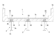
同図に示す合成桁1は、互いに平行に配置された複数の鋼製の主桁2と、各主桁2上に設置されたコンクリート製の床版3とからなる。
The
各主桁2は、ウエブ2aの上端及び下端にそれぞれ上フランジ2b及び下フランジ2cを有する鋼桁からなり、互いに橋軸直角方向に間隔をおいて複数列(例えば3列)に配置されている。また、上フランジ2bの上面には、主桁2と床版3とを結合するための複数のずれ止め部材としてのジベル2dが設けられている。ジベル2dは、上下方向に延びる金属製の棒状部材によって形成され、上端に他の部分よりも外径の大きい頭部を有する、いわゆるスタッドジベルからなる。このジベル2dは、橋軸直角方向に複数本(例えば3本)ずつ設けられるとともに、主桁2の長手方向一端側から他端側に亘って橋軸方向に間隔をおいて配列されている。
Each
床版3は、各主桁2の上フランジ2b上に図示しない型枠によって打設されたコンクリートにより形成され、その幅方向両側には壁高欄3aが一体に形成されている。床版3においては、各ジベル2dを埋め込んだ状態でコンクリートを打設することにより、各ジベル2dによって主桁2と床版3が結合されている。また、床版3の下面側には、各主桁2の上フランジ2b上にそれぞれ位置するハンチ3bが設けられ、各ハンチ3bは下方に向かって突出するように形成されている。この場合、ハンチ3bの側面は上フランジ2bの両側から床版3の下面まで傾斜面をなすように形成されている。また、床版3の上面にはアスファルト舗装3cが設けられている。
The
次に、前記合成桁1において、老朽化した床版の取替作業を行う際に、既設の床版3を撤去する方法を説明する。本実施形態の床版撤去方法では、床版3のジベル配置箇所を削孔するドリル10と、ドリル10を主桁2に橋軸方向に移動自在に支持する支持装置20と、切断された床版3を主桁2から剥離する床版剥離装置30を用いる。
Next, a method of removing the existing
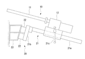
ドリル10には、コンクリートを円柱状にくり抜くことによってコンクリートを削孔する周知のコアドリルが用いられる。ドリル10は、円筒状の刃からなる刃部11と、刃部11を支持するドリル本体12とからなり、ドリル本体12の駆動モータ(図示せず)によって刃部11を回転するようになっている。このドリル10では、刃部11でコンクリートを削孔することにより、コンクリートに所望の深さの円形の孔からなる削孔部を形成するとともに、削孔部内に位置していた円柱状のコンクリートを取り出すようになっている。また、刃部11には、ジベル2dの外径(例えば19mm,22mm)よりも大きい外径(例えば50mm)のものが用いられる。
As the
支持装置20は、ドリル10のドリル本体12をドリル10の前後方向(ドリル軸方向)に移動自在に支持する移動機構21と、移動機構21をドリル10の左右方向に移動自在に支持する上下一対の支持部材22と、各支持部材22が固定される固定部材としての左右一対の架台23とからなる。
The supporting
移動機構21は、ドリル10の前後方向に延びるレール状の支持部材21aと、支持部材21aの前端が固定された基板21bとを有し、ドリル本体12側のハンドル21cを回動することにより、ドリル10が支持部材21aに沿って前後方向に移動するようになっている。また、基板21bはボルト21d及びナット21eによって支持部材22に取り付けられるようになっており、基板21bにはボルト21dを挿通するボルト挿通孔21fが設けられている。
The
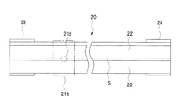
各支持部材22は、ドリル10の左右方向に延びる横断面四角形状の中空の部材からなり、ボルト22a及びナット22bによって各架台23に固定されている。各支持部材22は、互いに上下方向に隙間Sをおいて配置され、隙間Sは移動機構21のボルト21dを挿通可能な間隔になっている。これにより、各支持部材22の背面側から隙間Sに挿通したボルト21dを移動機構21の基板21bのボルト挿通孔21fに挿通し、基板21bをナット21eで各支持部材22に締結することにより、基板21bが各支持部材22の前面に固定されるようになっている。また、ナット21eを緩めるとともに、ボルト21dを隙間Sに沿って各支持部材22の長手方向にずらすことにより、ドリル10を基板21bと共にドリル10の左右方向に移動可能になっている。
Each
各架台23は、横断面四角形状の部材からなり、それぞれ各支持部材22の両端側に位置するように互いにドリル10の左右方向に間隔をおいて配置されている。各架台23の前面23aは垂直方向に対して所定角度θ(例えば15゜)だけ下方に向かって傾斜するように形成されており、前面23aに固定される各支持部材22及びドリル10が角度θだけ傾斜するようになっている。各架台23は、ボルト23b及びナット23cによって主桁2のウエブ2aに固定されるようになっており、ウエブ2aには床版取替工事の施工時にボルト23bを挿通するためのボルト挿通孔2eが設けられる。
Each
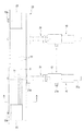
床版剥離装置30は、互いに橋軸方向に間隔をおいて配置される一対の第1の脚部31と、橋軸方向一方の脚部31の下方に配置される第2の脚部32と、長手方向両端側をそれぞれ各第1の脚部31に支持される梁部33と、床版3に締結する一対の締結部材34と、梁部33に対して締結部材34を上昇させる複数のジャッキ35とからなる。締結部材34は、ジャッキ35に支持される上部ロッド34aと、床版3に締結する下部ロッド34bとからなり、上部ロッド34a及び下部ロッド34bは結合部材34cによって互いに着脱自在に連結されている。また、下部ロッド34bには吊り上げ用ワイヤを連結するための連結部34dが設けられている。
The floor
ここで、本実施形態の床版撤去方法について、図8乃至図18を参照して説明する。まず、図8に示すように、ドリル10を支持装置20によって主桁2のウエブ2aの幅方向一方の面に取り付け、ドリル10によって床版3のジベル配置箇所を主桁2の幅方向一方から削孔することにより削孔部3dを形成する。即ち、支持装置20の移動機構21によってドリル10を前方に移動させ、ドリル10の刃部11により、床版3の下面側から斜め上方に向かって床版3のコンクリートをジベル2dごと削孔することによりジベル2dを切断する。その際、主桁2の幅方向3本のジベル2dのうち手前から2本のジベル2dのみを切断する深さまで刃部11が到達するように削孔する。この削孔作業は、支持装置20に支持されたドリル10を橋軸方向にずらすことにより、ドリル10をジベル配置箇所に順次移動し、各主桁2のジベル配置箇所ごとに行う。
Here, the floor slab removal method of the present embodiment will be described with reference to FIGS. 8 to 18. First, as shown in FIG. 8, the
次に、図9に示すように、ドリル10を支持装置20によって主桁2のウエブ2aの幅方向他方の面に取り付け、ドリル10によって床版3のジベル配置箇所を主桁2の幅方向他方から削孔することにより削孔部3dを形成する。即ち、支持装置20の移動機構21によってドリル10を前方に移動させ、ドリル10の刃部11により、床版3の下面側から斜め上方に向かって床版3のコンクリートをジベル2dごと削孔することによりジベル2dを切断することにより削孔部3dを形成する。即ち、前述と同様、支持装置20の移動機構21によってドリル10を前方に移動させ、ドリル10の刃部11により、床版3の下面側から斜め上方に向かって床版3のコンクリートをジベル2dごと削孔することによりジベル2dを切断する。その際、主桁2の幅方向3本のジベル2dのうち手前から1本のジベル2dのみを切断する深さまで削孔する。この削孔作業は、前述と同様、ドリル10をジベル配置箇所に順次移動し、各主桁2のジベル配置箇所ごとに行う。
Next, as shown in FIG. 9, the
前記削孔作業により、撤去しようとする床版3の全てのジベル2dを切断した後、図10に示すように、撤去区間の床版3を橋軸方向所定位置C1 で橋軸直角方向に切断するとともに、図11に示すように、床版3を幅方向両側の主桁2の幅方向外側端部位置C2 で橋軸方向に切断し、図12に示すように、壁高欄3a付近の床版3の一部を壁高欄3aと共に図示しないクレーンで撤去する。
After cutting all the
この後、床版剥離装置30を設置し、床版剥離装置30によって撤去区間の床版3の残りの部分を撤去する。床版剥離装置30は、図13に示すように、第1の脚部31が撤去区間の床版3を間にして橋軸方向に間隔をおいて配置され、橋軸方向両側の第1の脚部31によって梁部33が支持される。その際、橋軸方向一方の第1の脚部31は撤去区間外の床版3上に載置され、橋軸方向他方の第1の脚部31は、床版撤去済みの主桁2上に第2の脚部32を介して載置される。また、締結ロッド34及びジャッキ35は梁部33の2箇所に長手方向(橋軸方向)に間隔をおいて配置され、締結ロッド34の下部ロッド34bは撤去区間の床版3を上下方向に貫通し、床版3に締結されている。また、床版剥離装置30は、図14に示すように橋軸直角方向に間隔をおいて3箇所に設置される。そして、図15に示すように、各床版剥離装置30の締結ロッド34をジャッキ35によって上昇させることにより、床版3を各主桁2から剥離する。
Thereafter, the floor
次に、各床版剥離装置30の下部ロッド34bの連結部34dに図示しないクレーンの吊り上げ用ワイヤ40を連結し、図16及び図17に示すように、床版3をワイヤ40で吊り下げた状態で上部ロッド34a及び下部ロッド34bの結合を解除するとともに、下部ロッド34b以外の床版剥離装置30を除去し、床版3をクレーンで撤去する。
Next, a
この後、図18に示すように、各主桁2上の残存コンクリート屑の撤去、各主桁2上に一部が残存した残存ジベル2d′の切断、撤去、主桁2の表面仕上げを行う。残存ジベル2d′はフェイスカッター等により切断し、残存コンクリートは、ケレン棒やチッパー等により撤去、収集する。
After that, as shown in FIG. 18, the residual concrete scraps on each
このように、本実施形態によれば、複数のジベル2dによって主桁2と床版3が結合された合成桁1から床版3を撤去する方法において、床版3の下面側からジベル2dに向かって床版3のコンクリートをジベル2dごと削孔することによりジベル2dを切断し、ジベル2dが切断された床版3を主桁2から剥離して撤去するようにしたので、床版撤去作業を効率よく行うことができる。即ち、床版3の下面側から削孔することによりジベル2dを切断するようにしているので、削孔作業を施工期間中の交通規制時間外に行うことができ、交通規制による交通への影響を少なくすることができる。また、従来のように主桁上のコンクリートを残して橋軸方向に床版を切断する必要がないので、切断作業を少なくすることができるとともに、主桁上の残存コンクリートの破砕作業も必要とせず、作業時間の短縮を図ることができる。更に、従来のように主桁上の残存コンクリートを破砕する必要がないので、大量のコンクリート屑の撤去や収集に長時間を要することがなく、コンクリートの破砕作業による騒音、振動、粉塵を発生させることもないので、市街地での作業においても周辺への悪影響が少ないという利点がある。
As described above, according to the present embodiment, in the method of removing the
また、ドリル10でジベル2dまで削孔する際、ハンチ3bの高さ寸法が大きければほぼ水平方向に削孔することができるが、ハンチ3bの高さ寸法が小さい場合は水平方向への削孔が困難になる。本実施形態では、床版3の下面側から斜め上方に向かって床版3のジベル配置箇所を削孔するようにしているので、ハンチ3bの高さ寸法が小さい場合でもジベル2dまで削孔することができる。
Further, when drilling up to the
この場合、複数のジベル2dを切断するために床版3の上面付近まで削孔すると、床版3が必要以上に損傷し、床版剥離装置30による床版3と主桁2の剥離が困難となる可能性がある。そこで、本実施形態では、主桁2の幅方向両側からそれぞれ床版3のジベル配置箇所を削孔することにより、主桁2の幅方向両側から一部のジベル2dずつ切断するようにしているので、床版3の下面側から斜め上方に向かって床版3のジベル配置箇所を削孔する場合でも、床版3の上面付近まで削孔する必要がなく、床版3を必要以上に損傷させることがないという利点がある。
In this case, if a hole is drilled near the upper surface of the
また、主桁2にドリル10を支持装置20により橋軸方向に移動自在に取り付け、ドリル10を橋軸方向のジベル配置箇所に順次移動させて床版3のジベル配置箇所をドリル10で削孔するようにしているので、ドリル10が支持装置20によって安定して支持された状態で削孔作業を行うことができるとともに、常に等しい角度で複数のジベル配置箇所を削孔することができ、削孔作業を容易且つ正確に行うことができる。
Further, the
この場合、支持装置20は、ドリル10を橋軸直角方向に移動自在に支持する移動機構21と、移動機構21を橋軸方向に移動自在に支持する上下一対の支持部材22と、各支持部材22が固定される左右一対の架台23とを有し、移動機構21を各架台23の傾斜した前面23aに固定することにより、ドリル10を斜めに支持するようにしたので、各架台23を前面23aの傾斜角度θが異なる他の架台に交換することにより、ハンチ3bの高さ寸法や現場の作業環境等に応じてドリル10の傾斜角度を変えることができる。
In this case, the
更に、削孔用のドリル10として、コンクリートを円柱状にくり抜くコアドリルを用いるようにしているので、削孔により取り出した円柱状のコンクリート内にジベル2dの切断部が含まれているか否かを容易に確認することができ、削孔作業を確実に行うことができる。
Further, as the
また、ジベル2dを切断した床版3を橋軸直角方向に切断し、橋軸方向に一部ずつ床版3の撤去及び新設を行うようにしているので、例えば昼間等の交通量の多い時間帯は交通規制を解除して床版3の下方でジベル配置箇所の削孔作業を行い、夜間等の交通量の少ない時間帯に交通規制をして一部の床版3の撤去及び新設を行うことにより、施工期間が長い場合でも全施工期間に亘って連続した交通規制を行う必要がなく、交通への影響をより少なくすることができる。
Moreover, since the
尚、前記実施形態では、床版3を撤去する主桁2の全てのジベル2dを削孔により切断するようにしているが、削孔による切断が必要なジベル2dの本数が、主桁2の上フランジ2bの変形等の損傷を生ずることなく床版剥離装置30により床版3と主桁2との剥離が可能な本数であれば、一部のジベル2dのみを削孔により切断し、他のジベル2dは床版剥離時に破断させるようにしてもよい。
In addition, in the said embodiment, although all the
また、前記実施形態では、ずれ止め部材としてスタッドジベルを示したが、ずれ止め部材としては、スタッドジベルに限定されるものではなく、他の形状からなるずれ止め部材であってもよい。 Further, in the above-described embodiment, the stud dowel is shown as the shift preventing member, but the shift preventing member is not limited to the stud dowel and may be a shift preventing member having another shape.
更に、前記実施形態では、ドリル10で削孔することによりジベル配置箇所を切断するようにしたものを示したが、例えばコンクリートカッターでジベル配置箇所を連続的に切断するなど、他の切断方法を用いるようにしてもよい。
Furthermore, in the above-described embodiment, the
また、前記実施形態では、主桁2として、ウエブ2aの上端及び下端にそれぞれ上フランジ2b及び下フランジ2cを有する鋼桁からなるものを示したが、桁の形状や材質は本実施形態に限定されるものではなく、例えば箱桁やコンクリート桁であってもよい。
Further, in the above-described embodiment, the
1…合成桁、2…主桁、2d…ジベル、3…床版、3d…削孔部、10…ドリル、20…支持装置、21…移動機構、22…支持部材、23…架台、30…床版剥離装置。
DESCRIPTION OF
Claims (7)
コンクリートをくり抜くように削孔するドリルを用いて前記床版のずれ止め部材の配置箇所を削孔することにより、前記床版の下面側からずれ止め部材に向かって床版のコンクリートをずれ止め部材の長さ方向一部ごとドリルでくり抜いて切断するとともに、ドリルで切断されたずれ止め部材の切断部を含むコンクリートを取り出し、
ずれ止め部材が切断された床版を桁から撤去する
ことを特徴とする合成桁の床版撤去方法。 In the floor slab removal method, a concrete floor slab is installed on the girder, and the floor slab is removed from the composite girder in which the girder and the floor slab are joined by the slip prevention member provided so as to extend in the vertical direction on the upper surface of the girder. ,
By using a drill for drilling holes in the concrete to drill the location of the slip prevention member of the floor slab, the slip prevention member for the concrete of the floor slab from the lower surface side of the floor slab toward the slip prevention member with cutting hollowed in the length direction part each drill, eject the concrete containing the cleavage portion of the displacement-preventing member which is cut with a drill,
A method of removing a floor slab of a synthetic girder, which comprises removing the floor slab from which the slip prevention member has been cut.
ことを特徴とする請求項1記載の合成桁の床版撤去方法。 The floor slab removal method for a synthetic girder according to claim 1, wherein the position where the shift prevention member of the floor slab is arranged is cut obliquely upward from the lower surface side of the floor slab.
ことを特徴とする請求項2記載の合成桁の床版撤去方法。 The floor slab removal method for a synthetic girder according to claim 2, wherein the disposition preventing members of the floor slab are cut from both sides in the width direction of the girder.
ことを特徴とする請求項1乃至3の何れか1項に記載の合成桁の床版撤去方法。 The floor slab removal method of the synthetic girder according to any one of claims 1 to 3, wherein a core drill for hollowing out concrete into a column shape is used as the drill .
ドリルを橋軸方向のずれ止め部材の配置箇所に順次移動させて床版のずれ止め部材の配置箇所をドリルで削孔する
ことを特徴とする請求項1乃至4の何れか1項に記載の合成桁の床版撤去方法。 It mounted for moving the drill Hashijiku direction to the girder,
Drill is sequentially moved to the placement position of Hashijiku direction of displacement preventing members are according to arrangement position of the displacement-preventing member slab in any one of claims 1 to 4, characterized in that the drilling with a drill How to remove the floor slab of the composite girder.
ことを特徴とする請求項5記載の合成桁の床版撤去方法。 A supporting device including a moving mechanism that movably supports the drill in a direction perpendicular to the bridge axis, a supporting member that movably supports the moving mechanism in the bridge axis direction, and a fixing member that fixes the supporting member to the girder is used. The method for removing a floor slab of a composite girder according to claim 5, wherein the drill is obliquely supported by fixing the moving mechanism to the inclined surface of the fixing member.
橋軸方向に一部ずつ床版の撤去及び新設を行う
ことを特徴とする請求項1乃至6の何れか1項に記載の合成桁の床版撤去方法。 Cut the floor slab that cut the slip prevention member in the direction perpendicular to the bridge axis,
The floor slab removal method for a composite girder according to any one of claims 1 to 6 , wherein the floor slab is partially removed and newly installed in the bridge axis direction.
Priority Applications (1)
| Application Number | Priority Date | Filing Date | Title |
|---|---|---|---|
| JP2015222845A JP6709037B2 (en) | 2015-11-13 | 2015-11-13 | Floor removal method for composite girder |
Applications Claiming Priority (1)
| Application Number | Priority Date | Filing Date | Title |
|---|---|---|---|
| JP2015222845A JP6709037B2 (en) | 2015-11-13 | 2015-11-13 | Floor removal method for composite girder |
Publications (2)
| Publication Number | Publication Date |
|---|---|
| JP2017089302A JP2017089302A (en) | 2017-05-25 |
| JP6709037B2 true JP6709037B2 (en) | 2020-06-10 |
Family
ID=58767287
Family Applications (1)
| Application Number | Title | Priority Date | Filing Date |
|---|---|---|---|
| JP2015222845A Active JP6709037B2 (en) | 2015-11-13 | 2015-11-13 | Floor removal method for composite girder |
Country Status (1)
| Country | Link |
|---|---|
| JP (1) | JP6709037B2 (en) |
Families Citing this family (10)
| Publication number | Priority date | Publication date | Assignee | Title |
|---|---|---|---|---|
| JP6792415B2 (en) * | 2016-11-02 | 2020-11-25 | 鹿島建設株式会社 | How to remove concrete slab and how to install new concrete slab |
| JP6999295B2 (en) * | 2017-06-19 | 2022-01-18 | オリエンタル白石株式会社 | How to remove the deck |
| CN111254844B (en) * | 2020-03-19 | 2021-10-08 | 付万菊 | Deviation-correcting and resetting device and method for bridge pier stud |
| JP7479994B2 (en) | 2020-08-21 | 2024-05-09 | 三井住友建設株式会社 | Method and equipment for removing composite girder decks |
| JP2022095247A (en) * | 2020-12-16 | 2022-06-28 | オリエンタル白石株式会社 | Hole drilling method, hole drilling device and concrete slab cutting method |
| JP6895201B1 (en) * | 2021-01-20 | 2021-06-30 | 極東興和株式会社 | How to remove concrete deck |
| CN113931083B (en) * | 2021-09-25 | 2023-08-11 | 安徽惠农建设集团有限公司 | Assembled beam slab bridge reinforcing structure and reinforcing method thereof |
| CN114575260B (en) * | 2022-03-22 | 2023-09-22 | 中铁宝桥(扬州)有限公司 | Positioning and adjusting device for steel plate composite beam |
| CN114855657A (en) * | 2022-06-14 | 2022-08-05 | 保利长大工程有限公司 | Method for quickly dismantling municipal overpass |
| JP7383847B1 (en) * | 2023-07-25 | 2023-11-20 | オリエンタル白石株式会社 | How to cut and remove concrete slabs |
Family Cites Families (5)
| Publication number | Priority date | Publication date | Assignee | Title |
|---|---|---|---|---|
| JPH0643685B2 (en) * | 1989-05-26 | 1994-06-08 | ショーボンド建設株式会社 | Horizontal cutting method of bridge deck |
| JPH0533314A (en) * | 1991-07-31 | 1993-02-09 | Ishikawajima Harima Heavy Ind Co Ltd | Removing method of bridge floor plate |
| US5311629A (en) * | 1992-08-03 | 1994-05-17 | Smith Peter J | Deck replacement system with improved haunch lock |
| JPH09158124A (en) * | 1995-12-06 | 1997-06-17 | Ishikawajima Constr Materials Co Ltd | Removing method of floor slab |
| JPH11152902A (en) * | 1997-11-20 | 1999-06-08 | Kumagai Gumi Co Ltd | Drilling device |
-
2015
- 2015-11-13 JP JP2015222845A patent/JP6709037B2/en active Active
Also Published As
| Publication number | Publication date |
|---|---|
| JP2017089302A (en) | 2017-05-25 |
Similar Documents
| Publication | Publication Date | Title |
|---|---|---|
| JP6709037B2 (en) | Floor removal method for composite girder | |
| JP4709665B2 (en) | Replacement method for bridge concrete slab and concrete slab. | |
| JP6493362B2 (en) | Removal method of existing concrete slab | |
| JP6826872B2 (en) | How to remove concrete slab and how to install new concrete slab | |
| JP5794941B2 (en) | How to remove concrete slab | |
| CN103362078A (en) | Old frame bridge dismantling method in new-old frame bridge replacing process | |
| JP5439278B2 (en) | How to remove temporary support concrete | |
| JP7175780B2 (en) | How to form an opening in concrete | |
| JP6569951B2 (en) | Concrete wall demolition repair method | |
| JPH02311605A (en) | Horizontal cutting method for bridge floor system | |
| WO2006054094A1 (en) | Method of breaking down concrete piles | |
| JP6792415B2 (en) | How to remove concrete slab and how to install new concrete slab | |
| JPH09158124A (en) | Removing method of floor slab | |
| JP7160239B2 (en) | Propulsion method of box structure | |
| JP5276801B2 (en) | Labor-saving track reinforcement method | |
| JP6949614B2 (en) | Bridge deck dismantling equipment and bridge deck dismantling method | |
| JP6754219B2 (en) | Floor slab joint structure and floor slab renewal method | |
| JP6341027B2 (en) | Floor slab widening method | |
| JP6328736B1 (en) | How to remove existing concrete from bridges | |
| JP7363374B2 (en) | Repair method for concrete structures | |
| JP2007046291A (en) | Method of cutting and removing part of surface of structure | |
| JP4690764B2 (en) | Removal method of expansion joint | |
| CN104846753A (en) | Bridge deck opening maintaining method | |
| JP5758636B2 (en) | Synthetic floor slab manufacturing method | |
| JP7244967B1 (en) | How to remove the existing joint device |
Legal Events
| Date | Code | Title | Description |
|---|---|---|---|
| RD01 | Notification of change of attorney |
Free format text: JAPANESE INTERMEDIATE CODE: A7426 Effective date: 20160301 |
|
| A521 | Request for written amendment filed |
Free format text: JAPANESE INTERMEDIATE CODE: A821 Effective date: 20160301 |
|
| A621 | Written request for application examination |
Free format text: JAPANESE INTERMEDIATE CODE: A621 Effective date: 20180911 |
|
| A977 | Report on retrieval |
Free format text: JAPANESE INTERMEDIATE CODE: A971007 Effective date: 20190415 |
|
| A131 | Notification of reasons for refusal |
Free format text: JAPANESE INTERMEDIATE CODE: A131 Effective date: 20190508 |
|
| A521 | Request for written amendment filed |
Free format text: JAPANESE INTERMEDIATE CODE: A523 Effective date: 20190626 |
|
| A131 | Notification of reasons for refusal |
Free format text: JAPANESE INTERMEDIATE CODE: A131 Effective date: 20191106 |
|
| A521 | Request for written amendment filed |
Free format text: JAPANESE INTERMEDIATE CODE: A523 Effective date: 20191213 |
|
| TRDD | Decision of grant or rejection written | ||
| A01 | Written decision to grant a patent or to grant a registration (utility model) |
Free format text: JAPANESE INTERMEDIATE CODE: A01 Effective date: 20200507 |
|
| A61 | First payment of annual fees (during grant procedure) |
Free format text: JAPANESE INTERMEDIATE CODE: A61 Effective date: 20200522 |
|
| R150 | Certificate of patent or registration of utility model |
Ref document number: 6709037 Country of ref document: JP Free format text: JAPANESE INTERMEDIATE CODE: R150 |
|
| R250 | Receipt of annual fees |
Free format text: JAPANESE INTERMEDIATE CODE: R250 |
|
| S531 | Written request for registration of change of domicile |
Free format text: JAPANESE INTERMEDIATE CODE: R313531 |
|
| R350 | Written notification of registration of transfer |
Free format text: JAPANESE INTERMEDIATE CODE: R350 |