JP6707652B2 - Thermal transfer sheet - Google Patents
Thermal transfer sheet Download PDFInfo
- Publication number
- JP6707652B2 JP6707652B2 JP2018542520A JP2018542520A JP6707652B2 JP 6707652 B2 JP6707652 B2 JP 6707652B2 JP 2018542520 A JP2018542520 A JP 2018542520A JP 2018542520 A JP2018542520 A JP 2018542520A JP 6707652 B2 JP6707652 B2 JP 6707652B2
- Authority
- JP
- Japan
- Prior art keywords
- layer
- transfer
- thermal transfer
- transfer sheet
- thermal
- Prior art date
- Legal status (The legal status is an assumption and is not a legal conclusion. Google has not performed a legal analysis and makes no representation as to the accuracy of the status listed.)
- Active
Links
Images


Classifications
-
- B—PERFORMING OPERATIONS; TRANSPORTING
- B41—PRINTING; LINING MACHINES; TYPEWRITERS; STAMPS
- B41M—PRINTING, DUPLICATING, MARKING, OR COPYING PROCESSES; COLOUR PRINTING
- B41M5/00—Duplicating or marking methods; Sheet materials for use therein
- B41M5/50—Recording sheets characterised by the coating used to improve ink, dye or pigment receptivity, e.g. for ink-jet or thermal dye transfer recording
- B41M5/502—Recording sheets characterised by the coating used to improve ink, dye or pigment receptivity, e.g. for ink-jet or thermal dye transfer recording characterised by structural details, e.g. multilayer materials
-
- B—PERFORMING OPERATIONS; TRANSPORTING
- B41—PRINTING; LINING MACHINES; TYPEWRITERS; STAMPS
- B41M—PRINTING, DUPLICATING, MARKING, OR COPYING PROCESSES; COLOUR PRINTING
- B41M5/00—Duplicating or marking methods; Sheet materials for use therein
- B41M5/26—Thermography ; Marking by high energetic means, e.g. laser otherwise than by burning, and characterised by the material used
- B41M5/382—Contact thermal transfer or sublimation processes
- B41M5/38207—Contact thermal transfer or sublimation processes characterised by aspects not provided for in groups B41M5/385 - B41M5/395
- B41M5/38214—Structural details, e.g. multilayer systems
-
- B—PERFORMING OPERATIONS; TRANSPORTING
- B32—LAYERED PRODUCTS
- B32B—LAYERED PRODUCTS, i.e. PRODUCTS BUILT-UP OF STRATA OF FLAT OR NON-FLAT, e.g. CELLULAR OR HONEYCOMB, FORM
- B32B7/00—Layered products characterised by the relation between layers; Layered products characterised by the relative orientation of features between layers, or by the relative values of a measurable parameter between layers, i.e. products comprising layers having different physical, chemical or physicochemical properties; Layered products characterised by the interconnection of layers
- B32B7/02—Physical, chemical or physicochemical properties
-
- B—PERFORMING OPERATIONS; TRANSPORTING
- B41—PRINTING; LINING MACHINES; TYPEWRITERS; STAMPS
- B41M—PRINTING, DUPLICATING, MARKING, OR COPYING PROCESSES; COLOUR PRINTING
- B41M5/00—Duplicating or marking methods; Sheet materials for use therein
- B41M5/26—Thermography ; Marking by high energetic means, e.g. laser otherwise than by burning, and characterised by the material used
- B41M5/382—Contact thermal transfer or sublimation processes
- B41M5/392—Additives, other than colour forming substances, dyes or pigments, e.g. sensitisers, transfer promoting agents
- B41M5/395—Macromolecular additives, e.g. binders
-
- B—PERFORMING OPERATIONS; TRANSPORTING
- B41—PRINTING; LINING MACHINES; TYPEWRITERS; STAMPS
- B41M—PRINTING, DUPLICATING, MARKING, OR COPYING PROCESSES; COLOUR PRINTING
- B41M5/00—Duplicating or marking methods; Sheet materials for use therein
- B41M5/50—Recording sheets characterised by the coating used to improve ink, dye or pigment receptivity, e.g. for ink-jet or thermal dye transfer recording
- B41M5/52—Macromolecular coatings
-
- B—PERFORMING OPERATIONS; TRANSPORTING
- B41—PRINTING; LINING MACHINES; TYPEWRITERS; STAMPS
- B41M—PRINTING, DUPLICATING, MARKING, OR COPYING PROCESSES; COLOUR PRINTING
- B41M2205/00—Printing methods or features related to printing methods; Location or type of the layers
- B41M2205/02—Dye diffusion thermal transfer printing (D2T2)
-
- B—PERFORMING OPERATIONS; TRANSPORTING
- B41—PRINTING; LINING MACHINES; TYPEWRITERS; STAMPS
- B41M—PRINTING, DUPLICATING, MARKING, OR COPYING PROCESSES; COLOUR PRINTING
- B41M2205/00—Printing methods or features related to printing methods; Location or type of the layers
- B41M2205/06—Printing methods or features related to printing methods; Location or type of the layers relating to melt (thermal) mass transfer
-
- Y—GENERAL TAGGING OF NEW TECHNOLOGICAL DEVELOPMENTS; GENERAL TAGGING OF CROSS-SECTIONAL TECHNOLOGIES SPANNING OVER SEVERAL SECTIONS OF THE IPC; TECHNICAL SUBJECTS COVERED BY FORMER USPC CROSS-REFERENCE ART COLLECTIONS [XRACs] AND DIGESTS
- Y10—TECHNICAL SUBJECTS COVERED BY FORMER USPC
- Y10T—TECHNICAL SUBJECTS COVERED BY FORMER US CLASSIFICATION
- Y10T428/00—Stock material or miscellaneous articles
- Y10T428/24—Structurally defined web or sheet [e.g., overall dimension, etc.]
- Y10T428/24802—Discontinuous or differential coating, impregnation or bond [e.g., artwork, printing, retouched photograph, etc.]
- Y10T428/24843—Discontinuous or differential coating, impregnation or bond [e.g., artwork, printing, retouched photograph, etc.] with heat sealable or heat releasable adhesive layer
-
- Y—GENERAL TAGGING OF NEW TECHNOLOGICAL DEVELOPMENTS; GENERAL TAGGING OF CROSS-SECTIONAL TECHNOLOGIES SPANNING OVER SEVERAL SECTIONS OF THE IPC; TECHNICAL SUBJECTS COVERED BY FORMER USPC CROSS-REFERENCE ART COLLECTIONS [XRACs] AND DIGESTS
- Y10—TECHNICAL SUBJECTS COVERED BY FORMER USPC
- Y10T—TECHNICAL SUBJECTS COVERED BY FORMER US CLASSIFICATION
- Y10T428/00—Stock material or miscellaneous articles
- Y10T428/24—Structurally defined web or sheet [e.g., overall dimension, etc.]
- Y10T428/24942—Structurally defined web or sheet [e.g., overall dimension, etc.] including components having same physical characteristic in differing degree
Description
本発明は、熱転写シートに関する。 The present invention relates to a thermal transfer sheet.
被転写体上に転写層を転写するための熱転写シートについては各種の形態が知られており、例えば、特許文献1〜3に提案がされているような(i)基材の一方の面上に転写層としての熱溶融インキ層が設けられた熱転写シート、(ii)基材の一方の面上に転写層としての受容層が設けられた熱転写シート(中間転写媒体と称される場合もある)、(iii)基材の一方の面上に転写層としての保護層(剥離層と称される場合もある)が設けられた熱転写シート(保護層転写シートと称される場合もある)、(iv)これらの構成を適宜組合せた熱転写シート、例えば、基材の一方の面上に、当該基材側から、剥離層、受容層がこの順で積層されてなる積層構成の転写層が設けられた熱転写シートや、基材の同一面上に熱溶融インキ層と保護層が面順次に設けられた熱転写シート等が知られている。これらの熱転写シートの転写層は、被転写体と熱転写シートとを重ね合わせ、サーマルヘッドや、加熱ロール等の加熱手段によって基材の他方の面を加熱することにより、被転写体上に転写される。 Various forms are known for a thermal transfer sheet for transferring a transfer layer onto a transfer target, and, for example, (i) on one surface of a base material as proposed in
近時、高速印画適性に優れたプリンタに対する市場の要求は高く、プリンタの内部において、被転写体上に転写層を転写するときに熱転写シートにかかる熱エネルギーは増加の一途をたどっている。被転写体上への転写層の転写は、被転写体と熱転写シートの転写層とを密着させた状態で、熱転写シートに熱エネルギーを印加して被転写体上に転写層を転写し、被転写体上に転写済みの転写層を熱転写シートから剥離することにより行われる。なお、熱転写シートの転写層の転写に用いられるプリンタとしては、熱転写シートに熱エネルギーを印加して転写層を溶融或いは軟化させ、この転写層が固化する前に、被転写体上に転写済みの転写層のみを熱転写シートから剥離する熱時剥離方式のプリンタと、転写層が固化した後に、被転写体上に転写済みの転写層のみを熱転写シートから剥離する冷時剥離方式のプリンタが知られている。ところで、被転写体上に熱転写シートの転写層を転写する際に、被転写体と熱転写シートとが熱融着を起こした場合には、具体的には、熱転写シートから被転写体上に転写された転写層を剥離することができなくなる程度まで、被転写体と熱転写シートとが貼りついた場合、例えば、基材上に直接的に転写層が設けられた熱転写シートを用いて被転写体上に転写層を転写する際に、転写層と基材との意図しない熱融着が生じた場合には、プリンタの内部において、熱転写シートが破断してしまう、或いはプリンタ内部において、熱転写シートの搬送異常(JAMと称される場合もある)を引き起こすといった問題が生じやすくなる。特に、転写層を転写するときに熱転写シートに印加される熱エネルギーが高くなるにつれ、被転写体と熱転写シートとの熱融着や、熱融着に起因する搬送異常の発生頻度は高くなっていく傾向にある。 Recently, there is a high demand in the market for a printer excellent in high-speed printing suitability, and the thermal energy applied to the thermal transfer sheet when the transfer layer is transferred onto the transfer target inside the printer is steadily increasing. The transfer of the transfer layer onto the transfer target is performed by applying heat energy to the thermal transfer sheet and transferring the transfer layer onto the transfer target while the transfer target and the transfer layer of the thermal transfer sheet are in close contact with each other. This is performed by peeling the transfer layer that has been transferred onto the transfer body from the thermal transfer sheet. As a printer used for transferring the transfer layer of the thermal transfer sheet, heat energy is applied to the thermal transfer sheet to melt or soften the transfer layer, and before the transfer layer is solidified, it is transferred onto the transfer target. Known are a thermal peeling type printer that peels only the transfer layer from the thermal transfer sheet, and a cold peeling type printer that peels only the transfer layer that has been transferred onto the transfer target from the thermal transfer sheet after the transfer layer is solidified. ing. By the way, when thermal transfer between the transfer target and the thermal transfer sheet occurs when transferring the transfer layer of the thermal transfer sheet onto the transfer target, specifically, the transfer is performed from the thermal transfer sheet onto the transfer target. When the transfer target and the thermal transfer sheet are adhered to such an extent that the transferred transfer layer cannot be peeled off, for example, the transfer target is formed by using the thermal transfer sheet in which the transfer layer is directly provided on the base material. When unintentional thermal fusion between the transfer layer and the base material occurs when the transfer layer is transferred onto the transfer layer, the thermal transfer sheet is broken inside the printer, or the thermal transfer sheet inside the printer is broken. Problems such as transport abnormalities (sometimes called JAM) are likely to occur. In particular, as the thermal energy applied to the thermal transfer sheet when transferring the transfer layer increases, the thermal fusion between the transfer target and the thermal transfer sheet, and the occurrence frequency of conveyance abnormality due to the thermal fusion increases. Tends to go.
このような状況下、被転写体と熱転写シートとの熱融着を抑制するための種々の研究がなされているが、熱転写シートに高い熱エネルギーを印加して被転写体上に熱転写シートの転写層を転写した際に生じ得る被転写体と熱転写シートとの熱融着の対策については改善の余地が残されている。 Under such circumstances, various studies have been conducted to suppress thermal fusion between the transfer target and the thermal transfer sheet. However, high thermal energy is applied to the thermal transfer sheet to transfer the thermal transfer sheet onto the transfer target. There is still room for improvement in measures against heat fusion between the transfer target and the thermal transfer sheet that may occur when the layers are transferred.
また、近時、プリンタの小型化が進んでおり、その結果、プリンタ内での熱転写シートや、被転写体の搬送経路が、密集且つ複雑化する傾向にある。このような小型化が図られたプリンタを用いた場合には、被転写体上に転写層を転写する前の段階で、熱転写シートと被転写体、或いは、熱転写シートとプリンタの内部機構とが接触し、その際の衝撃等によって、プリンタの内部において熱転写シートから転写層の一部、又は全部が脱落する転写層の箔落ちが生じやすくなる。 Further, in recent years, the size of printers has been reduced, and as a result, the thermal transfer sheet and the transfer route of the transfer target in the printer tend to be dense and complicated. In the case of using such a miniaturized printer, the thermal transfer sheet and the transfer target body, or the thermal transfer sheet and the internal mechanism of the printer may be separated before the transfer layer is transferred onto the transfer target body. Due to the contact and the impact at that time, a part or the whole of the transfer layer falls off from the thermal transfer sheet inside the printer, so that the transfer layer may easily fall off.
本発明はこのような状況に鑑みてなされたものであり、熱転写シートに印加する熱エネルギーを高くしていった場合であっても、プリンタの内部において、被転写体と熱転写シートとが熱融着してしまうことを抑制でき、且つ、プリンタの内部において意図しない転写層の脱落を抑制することができる熱転写シートを提供することを主たる課題とする。 The present invention has been made in view of such circumstances, and even when the thermal energy applied to the thermal transfer sheet is increased, the transfer target and the thermal transfer sheet are thermally fused inside the printer. It is a main object to provide a thermal transfer sheet that can prevent the transfer layer from being worn and can prevent the transfer layer from unintentionally dropping inside the printer.
上記課題を解決するための本発明は、基材と、前記基材の一方の面上に設けられた転写層とを備える熱転写シートであって、前記転写層は、剥離層のみからなる単層構成、又は前記基材から最も近くに位置する剥離層を含む積層構成を呈しており、前記剥離層は、重量平均分子量(Mw)が70000以上92000以下で、且つガラス転移温度(Tg)が70℃以上100℃以下のアクリル系樹脂を含有しており、前記剥離層の厚みが0.2μm以上0.6μm以下であり、被転写体上に前記転写層を転写し、前記被転写体上に転写後の前記転写層の表面を、JIS−R−3255(1997)に準拠したマイクロスクラッチ法で測定したときの臨界せん断応力が0.9×10⁸N/m2以上であり、且つ、前記転写層の剥離力が7.5×10−2N/cm以下であり、前記転写層の剥離力が、熱転写シート供給手段、加熱手段、熱転写シート巻取り手段、前記加熱手段と前記熱転写シート巻取り手段との間に位置し搬送経路に沿って搬送される熱転写シートの引張強度を測定する測定手段、前記加熱手段と前記測定手段との間に位置する剥離手段を有するプリンタを用い、印加エネルギー0.127mJ/dot、熱転写シートの搬送速度84.6mm/sec.の条件にて、被転写体上に前記転写層を転写しながら、前記被転写体上に転写された前記転写層を、50°の剥離角度で前記熱転写シートから剥離するタイミングにおいて、前記測定手段により測定される熱転写シートの引張強度である。
また、一実施形態の熱転写シートは、基材と、前記基材の一方の面上に設けられた転写層とを備える熱転写シートであって、前記転写層は、1つの層からなる単層構成、又は2つ以上の層が積層されてなる積層構成を呈しており、被転写体上に前記転写層を転写し、前記被転写体上に転写後の前記転写層の表面を、JIS−R−3255(1997)に準拠したマイクロスクラッチ法で測定したときの臨界せん断応力が0.9×10⁸N/m2以上であり、且つ、前記転写層の剥離力が7.5×10−2N/cm以下であり、前記転写層の剥離力が、熱転写シート供給手段、加熱手段、熱転写シート巻取り手段、前記加熱手段と前記熱転写シート巻取り手段との間に位置し搬送経路に沿って搬送される熱転写シートの引張強度を測定する測定手段、前記加熱手段と前記測定手段との間に位置する剥離手段を有するプリンタを用い、印加エネルギー0.127mJ/dot、熱転写シートの搬送速度84.6mm/sec.の条件にて、被転写体上に前記転写層を転写しながら、前記被転写体上に転写された前記転写層を、50°の剥離角度で前記熱転写シートから剥離するタイミングにおいて、前記測定手段により測定される熱転写シートの引張強度であることを特徴とする。
The present invention for solving the above problems is a thermal transfer sheet comprising a base material and a transfer layer provided on one surface of the base material, wherein the transfer layer is a single layer consisting of a release layer only. Or a laminated structure including a peeling layer located closest to the substrate, the peeling layer having a weight average molecular weight (Mw) of 70,000 or more and 92,000 or less and a glass transition temperature (Tg) of 70. C. or more and 100.degree. C. or less is contained, the thickness of the release layer is 0.2 .mu.m or more and 0.6 .mu.m or less, the transfer layer is transferred onto a transfer target, and the transfer target is transferred onto the transfer target. The surface of the transfer layer after transfer has a critical shear stress of 0.9×10 8 N/m 2 or more when measured by a micro scratch method according to JIS-R-3255 (1997), and The peeling force of the transfer layer is 7.5×10 −2 N/cm or less, and the peeling force of the transfer layer is a thermal transfer sheet supply unit, a heating unit, a thermal transfer sheet winding unit, the heating unit and the thermal transfer sheet winding unit. Using a printer having a measuring unit located between the heating unit and the measuring unit for measuring the tensile strength of the thermal transfer sheet conveyed along the conveying path, and a peeling unit located between the heating unit and the measuring unit, the applied energy 0.127 mJ/dot, thermal transfer sheet conveying speed 84.6 mm/sec. Under the condition of (1), the measuring means is transferred at a timing of peeling the transfer layer transferred onto the transfer body from the thermal transfer sheet at a peeling angle of 50° while transferring the transfer layer onto the transfer body. It is the tensile strength of the thermal transfer sheet measured by.
Further, the thermal transfer sheet of one embodiment is a thermal transfer sheet including a base material and a transfer layer provided on one surface of the base material, and the transfer layer is a single-layer structure composed of one layer. Or a laminated structure in which two or more layers are laminated, the transfer layer is transferred onto a transfer target, and the surface of the transfer layer after the transfer onto the transfer target is subjected to JIS-R. The critical shear stress is 0.9×10 8 N/m 2 or more when measured by the micro scratch method according to -3255 (1997), and the peeling force of the transfer layer is 7.5×10 −2. The peeling force of the transfer layer is N/cm or less, and the peeling force of the transfer layer is located between the thermal transfer sheet supply unit, the heating unit, the thermal transfer sheet winding unit, and the heating unit and the thermal transfer sheet winding unit, and along the conveyance path. Using a printer having a measuring unit for measuring the tensile strength of the conveyed thermal transfer sheet and a peeling unit located between the heating unit and the measuring unit, the applied energy was 0.127 mJ/dot, the conveying speed of the thermal transfer sheet was 84. 6 mm/sec. Under the condition of (1), the measuring means is transferred at a timing of peeling the transfer layer transferred onto the transfer body from the thermal transfer sheet at a peeling angle of 50° while transferring the transfer layer onto the transfer body. The tensile strength of the thermal transfer sheet measured by
また、前記臨界せん断応力が0.9×10⁸N/m2以上2×108N/m2以下の範囲内であってもよい。Further, the critical shear stress may be in the range of 0.9×10 8 N/m 2 or more and 2×10 8 N/m 2 or less.
本発明の熱転写シートによれば、熱転写シートに印加する熱エネルギーを高くしていった場合であっても、プリンタの内部において、被転写体と転写層とが熱融着してしまうことを抑制でき、また、プリンタの内部において、転写層が脱落してしまうことを抑制することができる。 According to the thermal transfer sheet of the present invention, even if the thermal energy applied to the thermal transfer sheet is increased, it is possible to prevent thermal transfer between the transfer target and the transfer layer inside the printer. It is possible to prevent the transfer layer from falling off inside the printer.
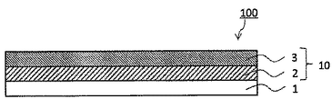
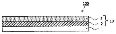
<<熱転写シート>>
以下、本発明の一実施形態の熱転写シート(以下、一実施形態の熱転写シートと言う場合がある)について詳細に説明する。図1〜図3は、一実施形態の熱転写シートの一例を示す概略断面図である。図1〜図3に示すように、一実施形態の熱転写シート100は、基材1と、当該基材1から剥離可能に設けられた転写層10とを備えている。転写層10は、図1、図2に示すように2つ以上の層が積層されてなる積層構成を呈していてもよく、図3に示すように、1つの層からなる単層構成を呈していてもよい。<< Thermal transfer sheet >>
Hereinafter, the thermal transfer sheet of one embodiment of the present invention (hereinafter, also referred to as the thermal transfer sheet of one embodiment) will be described in detail. 1 to 3 are schematic cross-sectional views showing an example of a thermal transfer sheet according to an embodiment. As shown in FIGS. 1 to 3, the
熱転写シートの転写層を被転写体上に転写するときに生じ得る問題の一つとして、被転写体と熱転写シートとの熱融着が挙げられる。なお、本願明細書で言う被転写体と熱転写シートとの熱融着とは、被転写体と熱転写シートとを重ね合わせ、熱転写シート側からサーマルヘッド等の加熱手段により熱エネルギーを印加して、被転写体上に転写層を転写し、被転写体上に転写された転写層のみを熱転写シートから剥離するときに、本来であれば、熱転写シート側に残存すべき熱転写シートの構成部材が、被転写体上に転写された転写層と一体化してしまい、被転写体上に転写された転写層のみを熱転写シートから剥離することができない現象を意味する。 One of the problems that can occur when the transfer layer of the thermal transfer sheet is transferred onto the transfer target is thermal fusion between the transfer target and the thermal transfer sheet. Incidentally, the thermal fusion of the transferred body and the thermal transfer sheet referred to in the present specification means that the transferred body and the thermal transfer sheet are superposed, and thermal energy is applied from the thermal transfer sheet side by a heating means such as a thermal head, When the transfer layer is transferred onto the transfer target and only the transfer layer transferred onto the transfer target is peeled from the thermal transfer sheet, the constituent member of the thermal transfer sheet that should originally remain on the thermal transfer sheet side is This means a phenomenon in which the transfer layer transferred onto the transfer target is integrated and only the transfer layer transferred onto the transfer target cannot be separated from the thermal transfer sheet.
より具体的には、例えば、基材上に直接的に転写層が設けられた熱転写シートを用いたときに、被転写体上に転写された転写層を基材から剥離することができない程度まで基材と転写層とが一体化してしまう現象を意味する。或いは、被転写体上に転写された転写層のみを熱転写シートから剥離することができたとしても、当該転写層の剥離時において異音等が生じる程度まで熱転写シートの構成部材が、被転写体上に転写された転写層と一体化してしまう現象を意味する。なお、被転写体と熱転写シートとが熱融着した場合には、プリンタ内での搬送異常や、転写不良等を引き起こす要因となる。また、被転写体と熱転写シートとの熱融着の程度が低い場合には、被転写体上に転写された転写層を熱転写シートから剥離することは可能ではあるものの、転写層の剥離界面が荒れてしまい、光沢度の低下等を引き起こすこととなる。 More specifically, for example, when a thermal transfer sheet in which a transfer layer is directly provided on a base material is used, the transfer layer transferred onto a transfer target cannot be separated from the base material. It means a phenomenon that the base material and the transfer layer are integrated. Alternatively, even if only the transfer layer transferred onto the transfer target can be peeled off from the thermal transfer sheet, the constituent members of the thermal transfer sheet are transferred to the transfer target to such an extent that abnormal noise is generated when the transfer layer is peeled off. It means a phenomenon that it is integrated with the transfer layer transferred on top. When the transfer-receiving member and the thermal transfer sheet are heat-sealed, they may cause a conveyance abnormality in the printer or a transfer failure. Further, when the degree of thermal fusion between the transfer target and the thermal transfer sheet is low, it is possible to peel the transfer layer transferred onto the transfer target from the thermal transfer sheet, but the peeling interface of the transfer layer is It becomes rough and causes a decrease in glossiness.
被転写体上に熱転写シートの転写層を転写するときに生じ得る被転写体と熱転写シートとの熱融着を抑制する対策として、例えば、転写層の耐熱性を向上させる対策や、基材からの転写層の剥離性を向上させる対策等がなされている。しかしながら、これらの対策がなされたことにより、所定の転写条件下においては被転写体と熱転写シートとの熱融着を抑制することができても、転写層を転写するときに熱転写シートに印加する熱エネルギーの条件によっては、被転写体と熱転写シートとの熱融着を十分に抑制することができないことも多く、被転写体上に転写層を転写するときの転写条件にかかわらず、被転写体と熱転写シートとの熱融着を十分に抑制できるまでには至っていないのが現状である。具体的には、転写層を転写するときに熱転写シートに印加する熱エネルギーを高くしていった場合等に、被転写体と熱転写シートとの熱融着を十分に抑制できるまでには至っていないのが現状である。 As a measure for suppressing thermal fusion between the transfer body and the thermal transfer sheet that may occur when the transfer layer of the thermal transfer sheet is transferred onto the transfer body, for example, a measure for improving the heat resistance of the transfer layer or a base material Measures for improving the releasability of the transfer layer are taken. However, due to these measures taken, even if the thermal fusion between the transfer target and the thermal transfer sheet can be suppressed under a predetermined transfer condition, it is applied to the thermal transfer sheet when transferring the transfer layer. Depending on the thermal energy conditions, it is often impossible to sufficiently suppress the thermal fusion between the transfer target and the thermal transfer sheet, and the transfer target is transferred regardless of the transfer conditions when the transfer layer is transferred onto the transfer target. The current situation is that the thermal fusion between the body and the thermal transfer sheet has not been sufficiently suppressed. Specifically, when the thermal energy applied to the thermal transfer sheet at the time of transferring the transfer layer is increased, thermal fusion between the transfer target and the thermal transfer sheet cannot be sufficiently suppressed. is the current situation.
このような状況において、被転写体との熱融着の発生を抑制することができる熱転写シートについて検討した結果、被転写体と熱転写シートとの熱融着は、被転写体上に転写された転写層10を、熱転写シートを構成する構成部材のうち当該転写層と直接的に接する構成部材(以下、転写層と接する構成部材と言う)から剥離するときの剥離力、例えば、基材1から剥離するときの剥離力と密接的な関係を有しており、当該剥離力を小さくしていくことで、かかる被転写体と熱転写シートとの熱融着の発生を抑制することができることを見出した。ところで、被転写体上に転写された転写層10を、転写層と接する構成部材から剥離するときの剥離力を、プリンタ内において正確に測定することは困難な状況にあり、被転写体と熱転写シートとの熱融着が発生する剥離力の臨界値を見出すことはできないといった問題がある。この点についてさらに検討を行ったところ、プリンタ内において、被転写体上に転写された転写層10を、転写層と接する構成部材から剥離するときの剥離力は、当該剥離時に熱転写シートにかかる引張強度と相関関係にあり、剥離時に熱転写シートにかかる引張強度と被転写体と熱転写シートとの熱融着との関係も密接的なものであることを見出した。以下、熱転写シートを構成する構成部材のうち転写層と直接的に接する構成部材が基材である場合を中心に説明するが、一実施形態の熱転写シートは、基材と転写層とが直接的に接している形態に限定されるものではなく、基材と転写層との間に任意の層を設けることもできる。この場合には、当該任意の層が転写層と直接的に接する構成部材となる。 In such a situation, as a result of studying a thermal transfer sheet capable of suppressing the occurrence of thermal fusion with the transferred body, the thermal fusion between the transferred body and the thermal transfer sheet was transferred onto the transferred body. Peeling force when the
係る点を考慮した一実施形態の熱転写シートは、以下の(条件1)を満たしていることを特徴の1つとしている。
(条件1):転写層10の剥離力が7.5×10⁻²N/cm以下であり、当該転写層10の剥離力が、熱転写シート100と被転写体とを重ね合わせ、図4に示すように、熱転写シート供給手段201、加熱手段202、熱転写シート巻取り手段203、加熱手段202と熱転写シート巻取り手段203との間に位置し搬送経路に沿って搬送される熱転写シートの引張強度を測定する測定手段204、加熱手段202と測定手段204との間に位置する剥離手段205を有するプリンタ200を用い、印加エネルギー0.127mJ/dot、熱転写シートの搬送速度84.6mm/sec.の条件にて、被転写体300上に転写層10を連続的に転写しながら、被転写体300上に転写された転写層10を、50°の剥離角度で熱転写シート100から剥離するタイミングにおいて、測定手段204により測定される熱転写シートの引張強度である。One of the features of the thermal transfer sheet of one embodiment in consideration of this point is that the following (condition 1) is satisfied.
(Condition 1): The peeling force of the
以下、熱転写シート供給手段201、加熱手段202、熱転写シート巻取り手段203、加熱手段202と熱転写シート巻取り手段203との間に位置し搬送経路に沿って搬送される熱転写シートの引張強度を測定する測定手段204、加熱手段202と測定手段204との間に位置する剥離手段205を有するプリンタ200を用い、印加エネルギー0.127mJ/dot、熱転写シートの搬送速度84.6mm/sec.の条件にて、被転写体300上に転写層10を連続的に転写しながら、被転写体300上に転写された転写層10を、50°の剥離角度で熱転写シート100側(例えば、基材1)から剥離するタイミングにおいて、測定手段204により測定される熱転写シートの引張強度のことを、単に、熱転写シートの引張強度と言う場合がある。 Hereafter, the tensile strength of the thermal transfer sheet feeding means 201, the heating means 202, the thermal transfer sheet winding means 203, and the tensile strength of the thermal transfer sheet which is located between the heating means 202 and the thermal transfer sheet winding means 203 and which is transported along the transport path is measured. Using the
本願明細書で言う印加エネルギー(mJ/dot)とは、下式(1)により算出される印加エネルギーであり、式(1)中の印加電力[W]は、下式(2)により算出することができる。
印加エネルギー(mJ/dot)=W×L.S.×P.D.×エネルギー階調値・・・(1)
(式(1)中の[W]は印加電力、[L.S.]はライン周期(msec./line)、[P.D.]はパルスDutyを意味する)
印加電力(W/dot)=V2/R・・・(2)
(式(2)中の[V]は印加電圧、[R]は加熱手段の抵抗値を意味する。)The applied energy (mJ/dot) referred to in the present specification is the applied energy calculated by the following formula (1), and the applied power [W] in the formula (1) is calculated by the following formula (2). be able to.
Applied energy (mJ/dot)=W×L.S. ×PD × Energy gradation value (1)
(In the formula (1), [W] means applied power, [LS] means line cycle (msec./line), and [PD] means pulse duty).
Applied power (W/dot)=V 2 /R (2)
(In the formula (2), [V] means the applied voltage and [R] means the resistance value of the heating means.)
また、本願明細書で言う熱転写シートの搬送速度(mm/sec.)は、下式(3)により算出される搬送速度である。
搬送速度(mm/sec.)=(25.4/(副走査方向の印字密度(dot/inch)×ライン周期(msec./line)))×1000・・・(3)
(式(3)中の25.4は、inchを、mmに換算するための数値である。)Further, the transport speed (mm/sec.) of the thermal transfer sheet referred to in the present specification is the transport speed calculated by the following formula (3).
Transport speed (mm/sec.)=(25.4/(printing density in the sub-scanning direction (dot/inch)×line period (msec./line)))×1000 (3)
(25.4 in the formula (3) is a numerical value for converting inch into mm.)
また、本願明細書でいう、測定手段により測定される引張強度(N/cm)とは、上記条件にて測定手段により測定される応力(N)を、熱転写シートの加熱幅(cm)で除した値である。 In addition, the tensile strength (N/cm) measured by the measuring means in the present specification means the stress (N) measured by the measuring means under the above conditions divided by the heating width (cm) of the thermal transfer sheet. It is the value.
上記(条件1)を満たす一実施形態の熱転写シートによれば、被転写体300上に転写層10を転写するときの各種の条件に影響を受けることなく、被転写体300上に転写層10を転写するときに生じ得る、被転写体300と熱転写シート100との熱融着を抑制することができる。具体的には、高速印画適性に対応すべく、熱転写シートに印加する熱エネルギーを高くしていった場合であっても、被転写体と熱転写シートとの熱融着を抑制することができる。 According to the thermal transfer sheet of the embodiment that satisfies the above (condition 1), the
さらに、転写条件にかかわらず、被転写体と熱転写シートとの熱融着の抑制を可能とした一実施形態の熱転写シート100によれば、基材1から転写層10を剥離するときに、転写層10に面荒れ等が生じることも抑制することができ、被転写体300上に転写された転写層10の光沢性を良好なものとすることができる。 Furthermore, regardless of the transfer conditions, according to the
なお、熱転写シートの引張強度を測定する条件として、印加エネルギー0.127mJ/dotとしているのは、印加エネルギー0.127mJ/dot未満としたときに、測定手段204により測定される熱転写シートの引張強度が7.5×10−2N/cm以下となっている場合であっても、印加エネルギー0.127mJ/dotとしたときの、測定手段204により測定される熱転写シートの引張強度が7.5×10−2N/cm以下となっていなければ、転写条件によっては、被転写体300と熱転写シート100との熱融着の発生を抑制することができないことによる。The applied energy of 0.127 mJ/dot is used as the condition for measuring the tensile strength of the thermal transfer sheet. The applied energy is less than 0.127 mJ/dot. Is 7.5×10 −2 N/cm or less, the tensile strength of the thermal transfer sheet measured by the measuring means 204 is 7.5 when the applied energy is 0.127 mJ/dot. If it is not less than ×10 −2 N/cm, generation of thermal fusion between the transferred
被転写体300上に、転写層10を転写するときに用いられるプリンタ200は、転写層を、50°の剥離角度で熱転写シート側から剥離するときのタイミングにおける熱転写シートの引張強度を測定することができるものであれば、転写層10を溶融或いは軟化させ、この転写層が固化する前に、転写済みの転写層10を基材1から剥離する熱時剥離方式のプリンタであってもよく、転写層10が固化した後に、転写済みの転写層10を基材1から剥離する冷時剥離方式のプリンタであってもよい。 The
なお、熱時剥離タイプのプリンタを用いる場合には、さらに、被転写体300上に転写層10を転写してから、0.05sec.後に当該被転写体300上に転写された転写層10を、50°の剥離角度で熱転写シート側から剥離するタイミングにおいて、測定手段204により測定される熱転写シートの引張強度が7.5×10⁻²N/cm以下となっていることが好ましい。この条件を満たす一実施形態の熱転写シート100によれば、熱時剥離方式のプリンタを用い、熱エネルギーの印加を終了してから、熱転写シート側から転写層10を剥離するまでの時間を短くしていった場合であっても被転写体300と熱転写シート100との熱融着の発生を十分に抑制することができる。When a thermal peeling type printer is used, further, after transferring the
(プリンタ)
次に、熱転写シートの引張強度を測定するためのプリンタについて説明する。(Printer)
Next, a printer for measuring the tensile strength of the thermal transfer sheet will be described.
図4に示すように、熱転写シートの引張強度の測定に用いられるプリンタ200は、熱転写シート100を所定の経路に沿って搬送する熱転写シート供給手段201としての熱転写シート供給ローラ、及び熱転写シート巻取り手段203としての巻上げローラ、熱転写シート100の背面側を加熱して被転写体300上に転写層10を転写する加熱手段202としてのサーマルヘッド、被転写体300を転写層10が転写される位置に移動可能なプラテンローラ206、加熱手段202と熱転写シート巻取り手段203との間に位置し、被転写体300上に転写層10を転写した後に、基材1から当該被転写体300上に転写された転写層10を剥離する剥離手段205としての剥離板、熱転写シート100の搬送経路上であって、加熱手段202(剥離手段205)と熱転写シート巻取り手段203との間に位置し、被転写体300上に転写層10を連続的に転写しながら、当該被転写体300上に転写された転写層10を、50°の剥離角度で熱転写シート100側から(例えば、基材1から)から剥離するタイミングにおいて、熱転写シートにかかる引張強度を測定する測定手段204としてのテンションメータを備えている。 As shown in FIG. 4, the
熱転写シートの引張強度の測定に用いられるプリンタ200は、熱転写シート100の搬送経路上であって、加熱手段202と熱転写シート巻取り手段203との間に位置し、被転写体300上に転写層10を転写しながら、基材1から当該被転写体300上に転写された転写層10を、50°の剥離角度で剥離するタイミングにおいて、熱転写シートの引張強度を測定する測定手段204を備えている点を除き、従来公知のプリンタを適宜設定して用いることができる。 The
測定手段204としては、搬送経路を走行中の熱転写シートの引張強度を測定することができるものであればよく、テンションメータ(ASK−1000 大倉インダストリー(株))を使用することができる。なお、本願明細書で言う引張強度は、張力と同義であり、引張強度の値は、被転写体300上に転写層10を転写した後に、基材1から当該被転写体300上に転写された転写層10を剥離するときの剥離力の実質的な値を示している。加熱手段202と熱転写シート巻取り手段203との間に、測定手段204を位置させたプリンタ200によれば、剥離手段205によって、被転写体300上に転写層10を転写しながら、基材1から当該被転写体300上に転写された転写層10を、50°の剥離角度で剥離するときの熱転写シートの引張強度の測定が可能となる。具体的には、被転写体300上に転写層10を連続的に転写しながら、当該被転写体上に転写された転写層10を基材1から連続的に剥離していくことで、転写層10を基材1から剥離していくときの実質的な剥離力の測定が可能となる。 As the measuring means 204, any means can be used as long as it can measure the tensile strength of the thermal transfer sheet running on the conveyance path, and a tension meter (ASK-1000 Okura Industry Co., Ltd.) can be used. It should be noted that the tensile strength referred to in the specification of the present application is synonymous with the tension, and the value of the tensile strength is transferred from the
剥離手段205は、加熱手段202と測定手段204との間に位置する剥離手段205との間に位置させればよく、その位置について特に限定はないが、熱時剥離タイプのプリンタとする場合には、被転写体300上に転写された転写層10が、0.05sec.後に剥離手段205に到達されるような位置に配置すればよく、一例としては、加熱手段202から搬送方向に向かって4.5mm離れた箇所に位置している。なお、加熱手段202から剥離手段205までの距離、及び熱転写シートの搬送速度に基づいて、被転写体300上に転写された転写層10が、剥離手段205によって剥離されるまでの時間を算出することができる。 The peeling means 205 may be positioned between the heating means 202 and the peeling means 205 positioned between the measuring means 204, and its position is not particularly limited, but in the case of a thermal peeling type printer, Indicates that the
一実施形態の熱転写シート100は、上記(条件1)とともに、以下の(条件2)を満たしていることを特徴の1つとしている。
(条件2):被転写体上に転写層10を転写し、被転写体上に転写後の転写層10の表面を、JIS−R−3255(1997)に準拠したマイクロスクラッチ法で測定したときの臨界せん断応力が0.9×10⁸N/m2以上である。
換言すれば、転写層10を構成する層のうち、基材1から最も近くに位置する層を、JIS−R−3255(1997)に準拠したマイクロスクラッチ法で測定したときの臨界せん断応力が0.9×10⁸N/m2以上である。One feature of the
(Condition 2): When the
In other words, among the layers constituting the
以下、被転写体上に転写層10を転写し、被転写体上に転写後の転写層10の表面を、JIS−R−3255(1997)に準拠したマイクロスクラッチ法で測定したときの臨界せん断応力のことを、単に臨界せん断応力と言う場合がある。また、被転写体上に転写層10を転写し、被転写体上に転写後の転写層10の表面に位置する層のことを転写層の転写界面に位置する層と言う場合がある。なお、被転写体上に転写後の転写層10の表面に位置する層は、転写層10を構成する層のうち基材1から最も近くに位置する層と同義である。 Hereinafter, the critical shear when the
上記(条件2)を満たす一実施形態の熱転写シート100によれば、転写層10の転写界面に位置する層の臨界せん断応力を0.9×10⁸N/m2以上とすることで、プリンタの内部において、熱転写シートと被転写体、或いは熱転写シートとプリンタの内部機構とが接触・衝突等した場合であっても、転写前の転写層の一部、或いは全部が、熱転写シート100から脱落してしまうことを抑制することができる。例えば、搬送経路が、密集、或いは複雑化された小型のプリンタを用いた場合には、熱転写シートは、被転写体や、プリンタの内部機構等と接触、或いは衝突しやすくなるものの、一実施形態の熱転写シートにおいては、上記(条件2)を満たすことにより、転写層10の転写界面に位置する層の強化が図られており、これにより、かかる接触等が生じた場合であっても、転写層10の意図しない脱落を抑制することができる。換言すれば、転写層の箔落ちを抑制することができる。According to the
なお、一実施形態の熱転写シート100において、臨界せん断応力が0.9×10⁸N/m2以上となる層を、転写層10を構成する層のうち、基材1から最も近くに位置する層としているのは、換言すれば、転写層10の転写界面に位置する層としているのは、転写層10の脱落は、転写層10の転写界面を起点として生じやすいことによる。一実施形態の熱転写シート100では、当該層の臨界せん断応力を0.9×108N/m2以上とすることで、転写層10の脱落の抑制が図られている。つまり、一実施形態の熱転写シート100は、上記(条件2)を満たすことにより、転写層10の転写界面に位置する層に、耐衝撃性を付与している点を特徴としている。In the
転写層10の転写界面に位置する層の臨界せん断応力の上限値について特に限定はないが、2×10⁸N/m2以下であることが好ましく、1.65×108N/m2以下であることがより好ましい。臨界せん断応力を0.9×108N/m2以上2×108N/m2以下の範囲、より好ましくは、0.9×108N/m2以上1.65×108N/m2以下の範囲とすることで、転写層10の脱落を抑制することができ、且つ転写層10を転写するときの箔切れ性の向上を図ることができる。本願明細書で言う転写層10の箔切れ性とは、転写層を被転写体上に転写する際の尾引きの抑制度合いを示し、箔切れ性が良好であるという場合には、尾引きの発生を十分に抑制可能であることを意味する。また、本願明細書で言う尾引きとは、転写層10を被転写体300上に転写するときに、転写層10の転写領域と非転写領域の境界を起点とし、該境界から非転写領域側にはみ出すように転写層10が転写されてしまう現象を意味する。The upper limit value of the critical shear stress of the layer located at the transfer interface of the
次に、上記(条件1)、及び(条件2)を満たす熱転写シート100の具体的な構成について一例を挙げて説明する。なお、一実施形態の熱転写シート100は、上記(条件1)、及び(条件2)を満たすものであればよく、これ以外についていかなる限定もされることはない。また、上記(条件1)、及び(条件2)を満たすための具体的な手段についても限定はなく、上記(条件1)、及び(条件2)を満たすことができるあらゆる手段を適用することができる。以下、上記(条件1)、及び(条件2)を満たすための具体的な手段について一例を挙げて説明するが、この手段に限定されるものではない。 Next, a specific configuration of the
(第1の手段)
第1の手段は、転写層10の転写界面に位置する層に含有せしめる成分を適宜選択して、転写層10の剥離力(熱転写シート100の引張強度)、及び転写層10の転写界面に位置する層の臨界せん断応力(転写層10を構成する層のうち、基材1から最も近くに位置する層の臨界せん断応力)を、上記(条件1)、及び(条件2)を満たすように調整する手段である。(First means)
The first means is to appropriately select the components to be contained in the layer located at the transfer interface of the
例えば、図1に示すように、基材1上に、当該基材1側から剥離層2、接着層3がこの順で積層されてなる積層構成の転写層10を設ける場合には、転写界面に位置する剥離層2に含有せしめる樹脂材料を適宜選択することで、例えば、樹脂材料の分子量、ガラス転移温度、或いは、当該樹脂材料をなすモノマー等を考慮することで、転写層10の剥離力、及び転写層10の転写界面に位置する層の臨界せん断応力を、上記(条件1)、及び(条件2)を満たすように調整することができる。以下、剥離層2が、転写層10の転写界面に位置する層である場合を中心に説明するが、転写層10の転写界面に位置する層は、これ以外の層であってもよい。 For example, as shown in FIG. 1, when a
一例としては、剥離層2に、重量平均分子量(Mw)が70000以上、且つガラス転移温度(Tg)が70℃以上100℃以下のアクリル系樹脂を含有せしめる手段を挙げることができる。重量平均分子量(Mw)が70000以上、且つガラス転移温度(Tg)が70℃以上100℃以下のアクリル系樹脂を含有する剥離層2とした場合には、当該剥離層2の厚みを調整することで、容易に、転写層10の剥離力、及び転写層10の転写界面に位置する層の臨界せん断応力を、上記(条件1)、(条件2)を満たすように調整することができる。なお、重量平均分子量(Mw)が70000以上、且つガラス転移温度(Tg)が70℃以上100℃以下のアクリル系樹脂を含有する剥離層2の厚みは、0.2μm以上0.6μm以下の範囲が好ましい。重量平均分子量(Mw)が70000以上、且つガラス転移温度(Tg)が70℃以上100℃以下のアクリル系樹脂を含有し、且つその厚みが0.2μm以上0.6μm以下の範囲の剥離層2とした場合には、上記(条件1)、(条件2)を満たすとともに、当該剥離層2を含む転写層10の箔切れ性を良好なものとすることができる。 As an example, there may be mentioned a means for allowing the
本願明細書で言う重量平均分子量(Mw)とは、JIS−K−7252−1(2008)に準拠し、GPC(ゲル浸透クロマトグラフィー)により測定したポリスチレン換算による重量平均分子量を意味する。また、本願明細書で言うガラス転移温度(Tg)とは、JIS−K−7121(2012)に準拠し、DSC(示差走査熱量測定)によって求められる温度を意味する。 The weight average molecular weight (Mw) referred to in the present specification means a polystyrene-equivalent weight average molecular weight measured by GPC (gel permeation chromatography) according to JIS-K-7252-1 (2008). Further, the glass transition temperature (Tg) referred to in the present specification means a temperature determined by DSC (Differential Scanning Calorimetry) according to JIS-K-7121 (2012).
また、一例としての剥離層2は、転写層10の剥離力、及び転写層10の転写界面に位置する層の臨界せん断応力が、上記(条件1)、(条件2)を満たす範囲で、上記重量平均分子量(Mw)が70000以上、且つガラス転移温度(Tg)が70℃以上100℃以下のアクリル系樹脂と、他の樹脂材料とを併用してもよい。他の樹脂材料としては、例えば、アクリル系樹脂、エポキシ系樹脂、ポリエステル系樹脂、スチレン系樹脂等を挙げることができる。 Further, the
また、他の一例として、剥離層2にセルロース系樹脂を含有せしめる手段を挙げることができる。セルロース系樹脂を含有する剥離層2とした場合には、当該剥離層2の厚みを調整することで、容易に、転写層10の剥離力、及び転写層10の転写界面に位置する層の臨界せん断応力を、上記(条件1)、(条件2)を満たすように調整することができる。セルロース系樹脂としては、例えば、セルロースアセテートプロピオネート(CAP)樹脂、セルロースアセテートブチレート(CAB)樹脂、ニトロセルロース樹脂等を挙げることができる。これ以外のセルロース系樹脂を用いて、転写層10の剥離力、及び転写層10の転写界面に位置する層の臨界せん断応力を、上記(条件1)、(条件2)を満たすように調整することもできる。 In addition, as another example, a means for allowing the
これ以外にも、剥離層2に、樹脂材料とともに、離型剤を含有せしめ、当該樹脂材料や、離型剤の種別、またこれらの含有量等を適宜決定することにより、転写層10の剥離力、及び転写層10の転写界面に位置する層の臨界せん断応力を、上記(条件1)、(条件2)を満たすように調整することもできる。離型剤としては、例えば、ポリエチレンワックス、シリコーンワックス等のワックス類、シリコーン樹脂、シリコーン変性樹脂、フッ素樹脂、フッ素変性樹脂、ポリビニルアルコール樹脂、アクリル系樹脂、熱硬化性エポキシ−アミノ共重合体、及び熱硬化性アルキッド−アミノ共重合体(熱硬化性アミノアルキド樹脂)等を挙げることができる。 In addition to this, the
(第2の手段)
第2の手段は、転写層10の転写界面に位置する層の厚みや、基材1の厚み、或いは基材1の他方の面上に設けられる任意の層の厚みを調整して、転写層10の剥離力、及び転写層10の転写界面に位置する層の臨界せん断応力を、上記(条件1)、及び(条件2)を満たすように調整する手段である。第2の手段によれば、基材1や、基材1の他方の面上に設けられる任意の層の厚みを適宜調整して、基材1の他方の面側から印加される熱エネルギーが転写層10に伝達される熱エネルギーの伝達効率を抑え、これにより、転写層10の剥離力が上記(条件1)を満たすように調整することができる。また、転写層10の転写界面に位置する層の厚みを適宜調整することで、当該転写界面に位置する層に耐久性を付与し、転写層10の転写界面に位置する層の臨界せん断応力を、上記(条件2)を満たすように調整することができる。また、基材1や、基材1の他方の面上に設けられる任意の層の厚みを調整する方法にかえて、基材1や、基材1の他方の面上に設けられる任意の層の材料として、熱エネルギーの伝達効率が低い材料を用いることで、基材1の他方の面側から印加される熱エネルギーが転写層10に伝達される熱エネルギーの伝達効率を抑えることもできる。(Second means)
The second means is to adjust the thickness of the layer located at the transfer interface of the
(第3の手段)
第3の手段は、基材1と転写層10との間に、転写層10の転写性を向上させる任意の層を設け、また、転写層10の転写界面に位置する層の厚みを適宜調整することで、転写層10の剥離力、及び転写層10の転写界面に位置する層の臨界せん断応力を、上記(条件1)、(条件2)を満たすように調整する手段である。任意の層としては、例えば、離型層等を挙げることができる。また、離型層の材料とともに、離型層の厚みを厚くする等の対策により、上記(条件1)を満たすように転写層10の剥離力を調整することもできる。(Third means)
The third means is to provide an arbitrary layer for improving the transferability of the
離型層に含有されるバインダー樹脂としては、例えば、ワックス類、シリコーンワックス、シリコーン樹脂、シリコーン変性樹脂、フッ素樹脂、フッ素変性樹脂、ポリビニルアルコール樹脂、アクリル系樹脂、熱硬化性エポキシ−アミノ共重合体、及び熱硬化性アルキッド−アミノ共重合体等が挙げられる。また、離型層は、1種の樹脂からなるものであってもよく、2種以上の樹脂からなるものであってもよい。離型層の厚みは0.2μm以上5μm以下の範囲が一般的である。 Examples of the binder resin contained in the release layer include waxes, silicone wax, silicone resin, silicone modified resin, fluororesin, fluorine modified resin, polyvinyl alcohol resin, acrylic resin, thermosetting epoxy-amino copolymer. Examples thereof include coalesce and thermosetting alkyd-amino copolymers. The release layer may be made of one kind of resin or two or more kinds of resin. The thickness of the release layer is generally in the range of 0.2 μm or more and 5 μm or less.
(第4の手段)
第4の手段は、転写層10の転写界面に位置する層の耐熱性を考慮して、転写層10の剥離力、及び転写層10の転写界面に位置する層の臨界せん断応力を、上記(条件1)、及び(条件2)を満たすように調整する手段である。転写層の耐熱性を向上させる手段としては、例えば、硬化剤によって硬化された硬化樹脂を含有せしめる方法等を挙げることができる。(Fourth means)
The fourth means considers the peeling force of the
また、転写層10自体の耐熱性を向上させることにかえて、或いはこれとともに、基材1の他方の面上に設けられる任意の層の耐熱性を向上させてもよい。 Further, instead of or in addition to improving the heat resistance of the
また、上記第1の手段〜第4の手段を適宜組合せて、転写層10の剥離力、及び転写層10の転写界面に位置する層の臨界せん断応力を、上記(条件1)、(条件2)を満たすように調整することもできる。また、これ以外の方法と組合せて上記(条件1)、及び(条件2)を満たすように調整することもできる。 In addition, by appropriately combining the above-mentioned first means to fourth means, the peeling force of the
以下、一実施形態の熱転写シート100の構成について一例を挙げて説明するが、一実施形態の熱転写シート100は、上記で説明した手段等を用いて、上記(条件1)、及び(条件2)を満たすように調整されている点を特徴とするものであり、これ以外の条件については、以下の記載に限定されるものではない。 Hereinafter, the configuration of the
(基材)
基材1は、一実施形態の熱転写シート100における必須の構成であり、基材1の一方の面上に設けられる転写層10、或いは、基材1と転写層10との間に設けられる任意の層(例えば、離型層(図示しない))を保持する。基材1の材料について特に限定はないが、転写層10を被転写体へ転写する際の熱エネルギー(例えば、サーマルヘッドの熱)に耐え得る耐熱性を有し、転写層10を支持できる機械的強度や耐溶剤性を有していることが好ましい。このような基材1の材料としては、例えば、ポリエチレンテレフタレート、ポリブチレンテレフタレート、ポリエチレンナフタレート、ポリエチレンテレフタレート−イソフタレート共重合体、テレフタル酸−シクロヘキサンジメタノール−エチレングリコール共重合体、ポリエチレンテレフタレート/ポリエチレンナフタレートの共押し出しフィルムなどのポリエステル系樹脂、ナイロン6、ナイロン66などのポリアミド系樹脂、ポリエチレン、ポリプロピレン、ポリメチルペンテンなどのポリオレフィン系樹脂、ポリ塩化ビニルなどのビニル系樹脂、ポリアクリレート、ポリメタアクリレート、ポリメチルメタアクリレートなどのアクリル系樹脂、ポリイミド、ポリエーテルイミドなどのイミド系樹脂、ポリアリレート、ポリスルホン、ポリエーテルスルホン、ポリフェニレンエーテル、ポリフェニレンスルフィド(PPS)、ポリアラミド、ポリエーテルケトン、ポリエーテルニトリル、ポリエーテルエーテルケトン、ポリエーテルサルファイトなどのエンジニアリング樹脂、ポリカーボネート、ポリスチレン、高衝撃性ポリスチレン、アクリロニトリル−スチレン共重合体(AS樹脂)、アクリロニトリル−ブタジエン−スチレン共重合体(ABS樹脂)などのスチレン系樹脂、セロファン、セルロースアセテート、ニトロセルロースなどのセルロース系樹脂などを挙げることができる。(Base material)
The
基材1の厚みについて特に限定はなく、一般的には、2.5μm以上100μm以下の範囲である。なお、基材1の厚みを上記一般的な範囲の厚みよりも厚くして、転写層10に伝達される熱エネルギーの伝達効率を抑え、これにより、転写層の剥離力が上記(条件1)を満たすように調整することもできる。 The thickness of the
また、基材1と転写層10との密着性を調整すべく、基材1の表面に各種の表面処理、例えば、コロナ放電処理、火炎処理、オゾン処理、紫外線処理、放射線処理、粗面化処理、化学薬品処理、プラズマ処理、低温プラズマ処理、プライマー処理、グラフト化処理等を施すこともできる。 Further, in order to adjust the adhesion between the
(転写層)
図1〜図3に示すように、基材1の一方の面上には、当該基材1から剥離可能な転写層10が設けられている。転写層10は、一実施形態の熱転写シート100における必須の構成である。(Transfer layer)
As shown in FIGS. 1 to 3, a
本願明細書で言う転写層10とは、熱転写時に基材1から剥離され被転写体に転写される層を意味する。転写層10は、最終的に、上記(条件1)、(条件2)を満たせば、その層構成や、転写層が含有する成分についていかなる限定もされることはない。図1、図2に示すように、転写層10は、2以上の層が積層されてなる積層構成を呈するものであってもよく、図3に示すように、転写層10は単層構成を呈していてもよい。また、基材1と転写層10との間に、離型層(図示しない)を設けてもよい。以下、転写層10について一例を挙げて説明する。 The
(第1形態の転写層)
第1形態の転写層10は、図1に示すように、基材1側から剥離層2、接着層3がこの順で積層されてなる積層構成を呈している。また、図1に示す形態にかえて、剥離層2上に接着層3を設けずに、剥離層2のみからなる単層構成の転写層10とし、この剥離層2自体に接着性を付与することもできる。第1形態の転写層10を備える熱転写シート100は、被転写体上に転写層10を転写して、被転写体の表面を保護する保護層転写シートとしての機能を果たす。接着層3については、中間転写媒体や、保護層転写シート等の分野において接着層の材料として従来公知のものを適宜選択して用いることができる。剥離層2の材料について特に限定はなく、例えば、上記第1の手段以外の手段によって、上記(条件1)、(条件2)を満たすように調整を行う場合には、従来公知の材料を適宜選択して用いることができる。なお、剥離層2を、保護層と称することもできる。(First Embodiment Transfer Layer)
As shown in FIG. 1, the
(第2形態の転写層)
第2形態の転写層10は、図2に示すように、基材1側から、剥離層2、受容層5がこの順で積層されてなる積層構成を呈している。第2形態の転写層10を備える熱転写シート100は、当該熱転写シートの受容層に熱転写画像を形成し、熱転写画像が形成された受容層を含む転写層を被転写体上に転写して、印画物を得るための中間転写媒体としての機能を果たす。受容層5については、熱転写受像シートや、中間転写媒体の分野で受容層の材料として従来公知のものを適宜選択して用いることができる。(Second Embodiment Transfer Layer)
As shown in FIG. 2, the
(第3形態の転写層)
第3形態の転写層10は、図3に示すように、熱溶融インキ層7から構成される単層構成を呈している。第3形態の転写層10を備える熱転写シート100は、被転写体上に熱溶融インキ層7を層ごと転写して被転写体上に熱転写画像を形成する機能を果たす。(Transfer layer of the third form)
As shown in FIG. 3, the
第3形態の転写層10においては、当該転写層10を構成する熱溶融インキ層7に含有される樹脂材料、離型剤等の成分、樹脂材料や、離型剤等の含有量等を考慮して、上記(条件1)、(条件2)を満たすように調整してもよく、また、上記第1の手段〜上記第4の手段を適宜選択して、上記(条件1)、(条件2)を満たすように調整してもよい。 In the
また、基材1の同一面上に、異なる転写層10を面順次に設けることもできる。例えば、基材1の同一面上に、転写層10としての熱溶融インキ層7と、転写層10としての剥離層2、接着層3との積層体を面順時に設けた熱転写シート100とすることもできる。 Further, different transfer layers 10 may be provided on the same surface of the
(任意の層)
一実施形態の熱転写シート100は、転写層を構成しない任意の層を備えていてもよい。任意の層としては、上記離型層(図示しない)や、基材1の他方の面上に設けられ、耐熱性や、サーマルヘッド等の加熱部材の層構成を向上させるための背面層等を挙げることができる。例えば、上記第3形態の転写層10を備える熱転写シートにおいて、基材1と転写層10としての熱溶融インキ層7との間に離型層を設けることもできる。(Any layer)
The
(被転写体)
一実施形態の熱転写シート100の転写層10が転写される被転写体について特に限定はなく、普通紙、上質紙、トレーシングペーパー、プラスチックフィルム、塩化ビニル、塩化ビニル−酢酸ビニル共重合体、ポリカーボネートを主体として構成されるプラスチックカード、熱転写受像シート、任意の対象物上に中間転写媒体の転写層が転写されてなる印画物等を挙げることができる。(Transfer material)
There is no particular limitation on the transfer target to which the
次に実施例及び比較例を挙げて本発明を更に具体的に説明する。以下、特に断りのない限り、部または%は質量基準である。また、Mwは重量平均分子量を意味し、Tgはガラス転移温度を意味する。 Next, the present invention will be described more specifically with reference to Examples and Comparative Examples. Hereinafter, unless otherwise specified, parts or% are based on mass. Moreover, Mw means a weight average molecular weight and Tg means a glass transition temperature.
(熱転写シート1の作成)
基材として厚さ4.5μmのポリエチレンテレフタレートフィルム(東レ(株))を用い、該基材の一方の面上に下記組成の剥離層用塗工液1を、乾燥後の膜厚が0.6μmとなるように塗布、乾燥して剥離層を形成した。次いで、剥離層上に、下記組成の接着層用塗工液を、乾燥時の膜厚が0.8μmとなるように塗布、乾燥して接着層を形成した。また、基材の他方の面上に、下記組成の背面層用塗工液を、乾燥後の膜厚が1μmとなるように塗布、乾燥して背面層を形成することで、基材の一方の面上に、剥離層、接着層がこの順で設けられ、基材の他方の面上に背面層が設けられた熱転写シート1を得た。なお、各実施例、及び比較例においては、剥離層、接着層の積層体が転写層を構成する。(Creation of thermal transfer sheet 1)
A 4.5 μm-thick polyethylene terephthalate film (Toray Industries, Inc.) was used as a base material, and a release
<剥離層用塗工液1>
・アクリル系樹脂(Mw:82000、Tg:84℃) 15部
(ダイヤナール(登録商標)MB−2952 三菱ケミカル(株))
・メチルエチルケトン 68部
・酢酸プロピル 17部<Release
-Acrylic resin (Mw: 82000, Tg: 84°C) 15 parts (Dianal (registered trademark) MB-2952 Mitsubishi Chemical Corporation)
・Methyl ethyl ketone 68 parts ・Propyl acetate 17 parts
<接着層用塗工液>
・ポリエステル樹脂 20部
(バイロン(登録商標)200 東洋紡(株))
・紫外線吸収剤 10部
(UVA−635L BASFジャパン社)
・メチルエチルケトン 80部<Coating liquid for adhesive layer>
・Polyester resin 20 parts (Byron (registered trademark) 200 Toyobo Co., Ltd.)
・
・Methyl ethyl ketone 80 parts
<背面層用塗工液>
・ポリビニルブチラール樹脂 10部
(エスレック(登録商標)BX−1 積水化学工業(株))
・ポリイソシアネート硬化剤 2部
(タケネート(登録商標)D218 三井化学(株))
・リン酸エステル 2部
(プライサーフ(登録商標)A208S 第一工業製薬(株))
・メチルエチルケトン 43部
・トルエン 43部<Back layer coating liquid>
・
-
-
・Methyl ethyl ketone 43 parts ・Toluene 43 parts
(熱転写シート2の作成)
剥離層用塗工液1を、乾燥後の膜厚が0.4μmとなるように塗布、乾燥して剥離層を形成した以外は全て熱転写シート1の作成と同様の方法で熱転写シート2を得た。(Creation of thermal transfer sheet 2)
The
(熱転写シート3の作成)
剥離層用塗工液1を、乾燥後の膜厚が0.2μmとなるように塗布、乾燥して剥離層を形成した以外は全て熱転写シート1の作成と同様の方法で熱転写シート3を得た。(Creation of thermal transfer sheet 3)
The thermal transfer sheet 3 was obtained in the same manner as in the preparation of the
(熱転写シート4の作成)
剥離層用塗工液1にかえて、下記組成の剥離層用塗工液2を、乾燥後の膜厚が0.6μmとなるように塗布、乾燥して剥離層を形成した以外は全て熱転写シート1の作成と同様の方法で、熱転写シート4を得た。(Creation of thermal transfer sheet 4)
Thermal transfer was performed except that the release
<剥離層用塗工液2>
・アクリル系樹脂(Mw:92000、Tg:84℃) 15部
(ダイヤナール(登録商標)MB−7033 三菱ケミカル(株))
・メチルエチルケトン 68部
・酢酸プロピル 17部<Release
Acrylic resin (Mw: 92000, Tg: 84° C.) 15 parts (Dianal (registered trademark) MB-7033 Mitsubishi Chemical Corporation)
・Methyl ethyl ketone 68 parts ・Propyl acetate 17 parts
(熱転写シート5の作成)
剥離層用塗工液2を、乾燥後の膜厚が0.4μmとなるように塗布、乾燥して剥離層を形成した以外は全て熱転写シート4の作成と同様の方法で熱転写シート5を得た。(Creation of thermal transfer sheet 5)
The
(熱転写シート6の作成)
剥離層用塗工液2を、乾燥後の膜厚が0.2μmとなるように塗布、乾燥して剥離層を形成した以外は全て熱転写シート4の作成と同様の方法で熱転写シート6を得た。(Creation of thermal transfer sheet 6)
The thermal transfer sheet 6 was obtained in the same manner as in the preparation of the thermal transfer sheet 4 except that the release
(熱転写シート7の作成)
剥離層用塗工液1にかえて、下記組成の剥離層用塗工液3を、乾燥後の膜厚が0.6μmとなるように塗布、乾燥して剥離層を形成した以外は全て熱転写シート1の作成と同様の方法で、熱転写シート7を得た。(Creation of thermal transfer sheet 7)
In place of the release
<剥離層用塗工液3>
・アクリル系樹脂(Mw:70000、Tg:76℃) 15部
(ダイヤナール(登録商標)MB−3015 三菱ケミカル(株))
・メチルエチルケトン 68部
・酢酸プロピル 17部<Release Layer Coating Liquid 3>
Acrylic resin (Mw: 70,000, Tg: 76° C.) 15 parts (Dianal (registered trademark) MB-3015 Mitsubishi Chemical Co., Ltd.)
・Methyl ethyl ketone 68 parts ・Propyl acetate 17 parts
(熱転写シート8の作成)
剥離層用塗工液3を、乾燥後の膜厚が0.4μmとなるように塗布、乾燥して剥離層を形成した以外は全て熱転写シート7の作成と同様の方法で熱転写シート8を得た。(Creation of thermal transfer sheet 8)
The thermal transfer sheet 8 was obtained in the same manner as in the preparation of the
(熱転写シート9の作成)
剥離層用塗工液3を、乾燥後の膜厚が0.2μmとなるように塗布、乾燥して剥離層を形成した以外は全て熱転写シート7の作成と同様の方法で熱転写シート9を得た。(Creation of thermal transfer sheet 9)
The thermal transfer sheet 9 was obtained in the same manner as the
(熱転写シート10の作成)
剥離層用塗工液1にかえて、下記組成の剥離層用塗工液4を、乾燥後の膜厚が0.6μmとなるように塗布、乾燥して剥離層を形成した以外は全て熱転写シート1の作成と同様の方法で、熱転写シート10を得た。(Creation of thermal transfer sheet 10)
Thermal transfer was performed except that a release layer coating liquid 4 having the following composition was applied in place of the release
<剥離層用塗工液4>
・ポリビニルブチラール樹脂(Tg:67℃) 10部
(エスレック(登録商標)BM−1 積水化学工業(株))
・メチルエチルケトン 45部
・トルエン 45部<Release layer coating liquid 4>
・Polyvinyl butyral resin (Tg: 67° C.) 10 parts (ESREC (registered trademark) BM-1 Sekisui Chemical Co., Ltd.)
・Methyl ethyl ketone 45 parts ・Toluene 45 parts
(熱転写シート11の作成)
剥離層用塗工液1にかえて、下記組成の剥離層用塗工液5を、乾燥後の膜厚が1μmとなるように塗布、乾燥して剥離層を形成した以外は全て熱転写シート1の作成と同様の方法で、熱転写シート11を得た。(Creation of thermal transfer sheet 11)
The
<剥離層用塗工液5>
・セルロースアセテートブチレート樹脂(Tg:101℃) 15部
(CAB−551−0.2 イーストマンケミカルジャパン(株))
・メチルエチルケトン 85部<Release
-Cellulose acetate butyrate resin (Tg: 101°C) 15 parts (CAB-551-0.2 Eastman Chemical Japan Co., Ltd.)
・Methyl ethyl ketone 85 parts
(熱転写シート12の作成)
剥離層用塗工液1にかえて、上記組成の剥離層用塗工液1を、乾燥後の膜厚が1μmとなるように塗布、乾燥して剥離層を形成した以外は全て熱転写シート1の作成と同様の方法で、熱転写シート12を得た。(Creation of thermal transfer sheet 12)
(熱転写シート13の作成)
剥離層用塗工液1にかえて、上記組成の剥離層用塗工液2を、乾燥後の膜厚が1μmとなるように塗布、乾燥して剥離層を形成した以外は全て熱転写シート1の作成と同様の方法で、熱転写シート13を得た。(Creation of thermal transfer sheet 13)
(熱転写シート14の作成)
剥離層用塗工液1にかえて、上記組成の剥離層用塗工液3を、乾燥後の膜厚が1.2μmとなるように塗布、乾燥して剥離層を形成した以外は全て熱転写シート1の作成と同様の方法で、熱転写シート14を得た。(Creation of thermal transfer sheet 14)
Thermal transfer except that the release
(熱転写シートAの作成)
剥離層用塗工液1にかえて、下記組成の剥離層用塗工液Aを、乾燥後の膜厚が0.6μmとなるように塗布、乾燥して剥離層を形成した以外は全て熱転写シート1の作成と同様の方法で、熱転写シートAを得た。(Creation of thermal transfer sheet A)
Thermal transfer was performed except that a release layer coating liquid A having the following composition was applied in place of the release
<剥離層用塗工液A>
・アクリル系樹脂(Mw:25000、Tg:105℃) 15部
(ダイヤナール(登録商標)BR−87 三菱ケミカル(株))
・メチルエチルケトン 68部
・酢酸プロピル 17部<Release layer coating liquid A>
-Acrylic resin (Mw: 25000, Tg: 105°C) 15 parts (Dianal (registered trademark) BR-87 Mitsubishi Chemical Co., Ltd.)
・Methyl ethyl ketone 68 parts ・Propyl acetate 17 parts
(熱転写シートBの作成)
剥離層用塗工液1にかえて、下記組成の剥離層用塗工液Bを、乾燥後の膜厚が0.6μmとなるように塗布、乾燥して剥離層を形成した以外は全て熱転写シート1の作成と同様の方法で、熱転写シートBを得た。(Creation of thermal transfer sheet B)
Thermal transfer was performed except that a release layer coating liquid B having the following composition was applied in place of the release
<剥離層用塗工液B>
・アクリル系樹脂(Mw:16000、Tg:50℃) 15部
(ダイヤナール(登録商標)BR−101 三菱ケミカル(株))
・メチルエチルケトン 68部
・酢酸プロピル 17部<Release layer coating liquid B>
Acrylic resin (Mw: 16000, Tg: 50° C.) 15 parts (Dianal (registered trademark) BR-101 Mitsubishi Chemical Co., Ltd.)
・Methyl ethyl ketone 68 parts ・Propyl acetate 17 parts
(熱転写シートCの作成)
剥離層用塗工液1にかえて、下記組成の剥離層用塗工液Cを、乾燥後の膜厚が0.6μmとなるように塗布、乾燥して剥離層を形成した以外は全て熱転写シート1の作成と同様の方法で、熱転写シートCを得た。(Creation of thermal transfer sheet C)
Thermal transfer was performed except that a release layer coating liquid C having the following composition was applied in place of the release
<剥離層用塗工液C>
・アクリル系樹脂(Mw:7000、Tg:57℃) 15部
(1FM−1072 大成ファインケミカル(株))
・メチルエチルケトン 85部<Release layer coating liquid C>
-Acrylic resin (Mw: 7,000, Tg: 57°C) 15 parts (1FM-1072 Taisei Fine Chemicals Co., Ltd.)
・Methyl ethyl ketone 85 parts
(熱転写シートDの作成)
剥離層用塗工液1にかえて、下記組成の剥離層用塗工液Dを、乾燥後の膜厚が0.6μmとなるように塗布、乾燥して剥離層を形成した以外は全て熱転写シート1の作成と同様の方法で、熱転写シートDを得た。(Creation of thermal transfer sheet D)
Thermal transfer was performed except that the release
<剥離層用塗工液D>
・塩化ビニル−酢酸ビニル共重合体(Mw:35,000、Tg:76℃)
15部
(ソルバイン(登録商標)CNL 日信化学工業(株))
・メチルエチルケトン 68部
・酢酸プロピル 17部<Release layer coating liquid D>
-Vinyl chloride-vinyl acetate copolymer (Mw: 35,000, Tg: 76°C)
15 copies (Solvine (registered trademark) CNL Nissin Chemical Industry Co., Ltd.)
・Methyl ethyl ketone 68 parts ・Propyl acetate 17 parts
(熱転写シートEの作成)
剥離層用塗工液1にかえて、上記組成の剥離層用塗工液5を、乾燥後の膜厚が0.6μmとなるように塗布、乾燥して剥離層を形成した以外は全て熱転写シート1の作成と同様の方法で、熱転写シートEを得た。なお、熱転写シートEは、熱転写シート11と、剥離層の厚みのみが異なっている。(Creation of thermal transfer sheet E)
Thermal transfer was performed except that the release
(引張強度の算出(剥離力の算出))
上記で作成した各熱転写シート、及び被転写体を組合せ、下記熱時剥離タイプのテストプリンタ1を用いて、被転写体上に、熱転写シートの転写層を転写しながら、剥離角度50°で、当該転写された転写層を基材から剥離することで、被転写体上に転写層が設けられた印画物を得た。なお、被転写体としては、昇華型熱転写プリンタ(DS−40 大日本印刷(株))の純正受像紙を使用した。
この印画物を得るにあたり、被転写体上に転写された転写層を、50°の剥離角度で基材から剥離するタイミングにおける熱転写シートの応力を、プリンタ内において、熱転写シートの巻取ロールと、加熱手段(サーマルヘッド)との間に設けられたテンションメータ(ASK−1000 大倉インダストリー(株))により測定した。次いで、テンションメータにて測定された応力を、熱転写シートの加熱幅(エネルギーの印加幅)で除することで引張強度の値を算出した。表1に引張強度の測定結果を示す。(Calculation of tensile strength (calculation of peeling force))
Each of the thermal transfer sheets created above and the transferred material are combined, and the transfer layer of the thermal transfer sheet is transferred onto the transferred material using the following thermal peeling
In obtaining this printed matter, the stress of the thermal transfer sheet at the timing of peeling the transfer layer transferred onto the transfer target from the base material at a peeling angle of 50° is set in the printer by a take-up roll of the thermal transfer sheet, It was measured with a tension meter (ASK-1000 Okura Industry Co., Ltd.) provided between the heating means (thermal head). Next, the stress measured by the tension meter was divided by the heating width (energy application width) of the thermal transfer sheet to calculate the value of tensile strength. Table 1 shows the measurement results of tensile strength.
(テストプリンタ1(熱時剥離タイプ))
・発熱体平均抵抗値:5241(Ω)
・主走査方向印字密度:300(dpi)
・副走査方向印字密度:300(dpi)
・印画電圧:28(V)
・印画電力:0.15(W/dot)
・印加エネルギー:0.127(mJ/dot)
・ライン周期:1(msec./line)
・パルスDuty:85(%)
・印画開始温度:29.0(℃)〜36.0(℃)
・発熱ポイントから剥離板までの距離:4.5(mm)
・搬送速度:84.6(mm/sec.)
・印圧:3.5〜4.0(kgf)(34.3〜39.2(N))
・評価画像(エネルギー階調):255/255階調画像(Test printer 1 (Peeling type during heat))
・Heating element average resistance value: 5241 (Ω)
-Print density in main scanning direction: 300 (dpi)
・Printing density in the sub-scanning direction: 300 (dpi)
・Print voltage: 28 (V)
・Print power: 0.15 (W/dot)
・Applied energy: 0.127 (mJ/dot)
・Line cycle: 1 (msec./line)
・Pulse Duty: 85(%)
-Printing start temperature: 29.0 (°C) to 36.0 (°C)
・Distance from heat generation point to release plate: 4.5 (mm)
・Conveying speed: 84.6 (mm/sec.)
-Printing pressure: 3.5 to 4.0 (kgf) (34.3 to 39.2 (N))
Evaluation image (energy gradation): 255/255 gradation image
(臨界せん断応力の測定)
上記引張強度の測定により得られた印画物の表面(剥離層の表面)を、JIS−R−3255(1997)に準拠したマイクロスクラッチ法で測定した。印画物表面(剥離層表面)の臨界せん断応力を表1に併せて示す。(Measurement of critical shear stress)
The surface of the print (the surface of the release layer) obtained by the measurement of the tensile strength was measured by the micro scratch method according to JIS-R-3255 (1997). Table 1 also shows the critical shear stress of the surface of the printed matter (release layer surface).
表1では、転写層の剥離力(熱転写シートの引張強度)、及び転写層の転写界面に位置する層の臨界せん断応力が、上記(条件1)、(条件2)を満たす熱転写シートを実施例の熱転写シートとし、上記(条件1)、及び上記(条件2)の何れか一方でも満たさない熱転写シートを比較例の熱転写シートとしている。 In Table 1, the thermal transfer sheet in which the peeling force of the transfer layer (tensile strength of the thermal transfer sheet) and the critical shear stress of the layer located at the transfer interface of the transfer layer satisfy the above (Condition 1) and (Condition 2) are shown in Examples. And the thermal transfer sheet that does not satisfy either (condition 1) or (condition 2) is used as the thermal transfer sheet of the comparative example.
(熱融着評価)
表1に示す各実施例、及び比較例の熱転写シートと、被転写体との組合せにおいて、以下の評価基準に基づいて、上記熱時剥離タイプのテストプリンタ1を用いて熱転写受像シート上に転写層を転写したときの熱融着の評価を行った。評価結果を表1に併せて示す。(Heat fusion evaluation)
In the combination of the thermal transfer sheet of each of the examples and comparative examples shown in Table 1 and the transfer target, the thermal transfer image was transferred onto the thermal transfer image-receiving sheet using the above-mentioned thermal peeling
「評価基準」
A:熱融着の発生がなく、基材から転写層を良好に剥離することができる。
NG:転写層の一部又は全部で熱融着が発生し、基材から転写層の一部又は全部を剥離することができない。"Evaluation criteria"
A: The transfer layer can be satisfactorily peeled from the base material without causing heat fusion.
NG: Thermal fusion occurs in part or all of the transfer layer, and part or all of the transfer layer cannot be separated from the base material.
(箔落ち評価)
表1に示す各実施例、及び比較例の組合せをなす各熱転写シートを、昇華型熱転写プリンタ(DS−40 大日本印刷(株))の純正リボンの保護層パネルに切り貼りし、温度22.5℃、湿度50%の環境下に1時間放置した後に、上記昇華型熱転写プリンタを用い、128/255エネルギー階調条件で、当該昇華型熱転写プリンタの純正受像紙に、各実施例、及び比較例の組合せに用いた熱転写シートの転写層を転写し印画物を得た。転写後の印画物表面の状態を目視で確認し、以下の評価基準に基づいて、転写層の箔落ち評価を行った。評価結果を表1に併せて示す。なお、箔落ちが生じているとは、プリンタ内部において、転写層の一部、或いは全部が脱落していることを意味する。(Foil removal evaluation)
Each thermal transfer sheet forming a combination of each of the examples shown in Table 1 and the comparative example was cut and pasted on a protective layer panel of a genuine ribbon of a sublimation type thermal transfer printer (DS-40 Dai Nippon Printing Co., Ltd.), and a temperature of 22.5. After being left in an environment of ℃ and humidity of 50% for 1 hour, the above-mentioned sublimation type thermal transfer printer was used under the 128/255 energy gradation condition, and each of the examples and the comparative examples were printed on the genuine image receiving paper of the sublimation type thermal transfer printer. The transfer layer of the thermal transfer sheet used in the above combination was transferred to obtain a printed matter. The state of the surface of the printed matter after the transfer was visually confirmed, and the foil removal of the transfer layer was evaluated based on the following evaluation criteria. The evaluation results are also shown in Table 1. The foil peeling means that part or all of the transfer layer has fallen off inside the printer.
「評価基準」
A:転写層の箔落ちが生じておらず、印画物に欠点がない。
NG:転写層の箔落ちによる印画物欠点が確認できる。"Evaluation criteria"
A: Foil removal of the transfer layer did not occur, and the printed matter had no defects.
NG: A defect of the printed matter due to the foil falling off of the transfer layer can be confirmed.
(箔切れ性評価)
上記転写層の箔落ち評価で得られた印画物の端部の尾引きの状態を確認し、以下の評価基準に基づいて箔切れ性の評価を行った。評価結果を表1に示す。なお、箔切れ性の評価は実施例の熱転写シートについてのみ行った。(Foil breakage evaluation)
The trailing state of the end of the printed matter obtained by the evaluation of the foil drop of the transfer layer was confirmed, and the foil breakability was evaluated based on the following evaluation criteria. The evaluation results are shown in Table 1. The evaluation of foil breakability was performed only for the thermal transfer sheets of the examples.
「評価基準」
A:尾引きの発生なし。
B:尾引きの長さが1.0mm未満。
C:尾引きの長さが1.0mm以上。"Evaluation criteria"
A: No tailing occurred.
B: The length of tailing is less than 1.0 mm.
C: The length of the tail is 1.0 mm or more.

1…基材
2…剥離層
3…接着層
5…受容層
7…熱溶融インキ層
10…転写層
100…熱転写シート
200…プリンタ
201…熱転写シート供給手段(供給ローラ)
202…加熱手段(サーマルヘッド)
203…熱転写シート巻取り手段(巻上げローラ)
204…測定手段(テンションメータ)
205…剥離手段(剥離板)
300…被転写体DESCRIPTION OF
202... Heating means (thermal head)
203... Thermal transfer sheet winding means (winding roller)
204... Measuring means (tension meter)
205... Peeling means (peeling plate)
300... Transferee
Claims (3)
前記転写層は、剥離層のみからなる単層構成、又は前記基材から最も近くに位置する剥離層を含む積層構成を呈しており、
前記剥離層は、重量平均分子量(Mw)が70000以上92000以下で、且つガラス転移温度(Tg)が70℃以上100℃以下のアクリル系樹脂を含有しており、
前記剥離層の厚みが0.2μm以上0.6μm以下であり、
被転写体上に前記転写層を転写し、前記被転写体上に転写後の前記転写層の表面を、JIS−R−3255(1997)に準拠したマイクロスクラッチ法で測定したときの臨界せん断応力が0.9×10⁸N/m2以上であり、且つ、
前記転写層の剥離力が7.5×10⁻²N/cm以下であり、
前記転写層の剥離力が、熱転写シート供給手段、加熱手段、熱転写シート巻取り手段、前記加熱手段と前記熱転写シート巻取り手段との間に位置し搬送経路に沿って搬送される熱転写シートの引張強度を測定する測定手段、前記加熱手段と前記測定手段との間に位置する剥離手段を有するプリンタを用い、印加エネルギー0.127mJ/dot、熱転写シートの搬送速度84.6mm/sec.の条件にて、被転写体上に前記転写層を転写しながら、前記被転写体上に転写された前記転写層を、50°の剥離角度で前記熱転写シートから剥離するタイミングにおいて、前記測定手段により測定される熱転写シートの引張強度であることを特徴とする熱転写シート。A thermal transfer sheet comprising a base material and a transfer layer provided on one surface of the base material,
The transfer layer has a single-layer structure consisting of only a peeling layer, or a laminated structure including a peeling layer located closest to the base material,
The release layer contains an acrylic resin having a weight average molecular weight (Mw) of 70,000 or more and 92,000 or less and a glass transition temperature (Tg) of 70° C. or more and 100° C. or less,
The release layer has a thickness of 0.2 μm or more and 0.6 μm or less,
Critical shear stress when the transfer layer is transferred onto a transfer target, and the surface of the transfer layer after transfer onto the transfer target is measured by a micro scratch method according to JIS-R-3255 (1997). Is 0.9×10 8 N/m 2 or more, and
The peeling force of the transfer layer is 7.5×10 −2 N/cm or less,
The peeling force of the transfer layer is such that the thermal transfer sheet supply unit, the heating unit, the thermal transfer sheet winding unit, and the tension of the thermal transfer sheet that is located between the heating unit and the thermal transfer sheet winding unit and is transported along the transport path. Using a printer having a measuring unit for measuring strength and a peeling unit located between the heating unit and the measuring unit, the applied energy was 0.127 mJ/dot, the transfer speed of the thermal transfer sheet was 84.6 mm/sec. Under the condition of (1), the measuring means is transferred at a timing of peeling the transfer layer transferred onto the transfer body from the thermal transfer sheet at a peeling angle of 50° while transferring the transfer layer onto the transfer body. A thermal transfer sheet characterized by being the tensile strength of the thermal transfer sheet measured by.
Applications Claiming Priority (3)
| Application Number | Priority Date | Filing Date | Title |
|---|---|---|---|
| JP2016194746 | 2016-09-30 | ||
| JP2016194746 | 2016-09-30 | ||
| PCT/JP2017/034295 WO2018062039A1 (en) | 2016-09-30 | 2017-09-22 | Heat transfer sheet |
Related Child Applications (1)
| Application Number | Title | Priority Date | Filing Date |
|---|---|---|---|
| JP2019114879A Division JP2019206181A (en) | 2016-09-30 | 2019-06-20 | Thermal transfer sheet |
Publications (2)
| Publication Number | Publication Date |
|---|---|
| JPWO2018062039A1 JPWO2018062039A1 (en) | 2019-04-04 |
| JP6707652B2 true JP6707652B2 (en) | 2020-06-10 |
Family
ID=61760738
Family Applications (2)
| Application Number | Title | Priority Date | Filing Date |
|---|---|---|---|
| JP2018542520A Active JP6707652B2 (en) | 2016-09-30 | 2017-09-22 | Thermal transfer sheet |
| JP2019114879A Pending JP2019206181A (en) | 2016-09-30 | 2019-06-20 | Thermal transfer sheet |
Family Applications After (1)
| Application Number | Title | Priority Date | Filing Date |
|---|---|---|---|
| JP2019114879A Pending JP2019206181A (en) | 2016-09-30 | 2019-06-20 | Thermal transfer sheet |
Country Status (5)
| Country | Link |
|---|---|
| US (1) | US11104171B2 (en) |
| JP (2) | JP6707652B2 (en) |
| KR (1) | KR102325156B1 (en) |
| CN (1) | CN109689391B (en) |
| WO (1) | WO2018062039A1 (en) |
Cited By (1)
| Publication number | Priority date | Publication date | Assignee | Title |
|---|---|---|---|---|
| JP2019206181A (en) * | 2016-09-30 | 2019-12-05 | 大日本印刷株式会社 | Thermal transfer sheet |
Families Citing this family (1)
| Publication number | Priority date | Publication date | Assignee | Title |
|---|---|---|---|---|
| JP7413859B2 (en) | 2020-03-16 | 2024-01-16 | 大日本印刷株式会社 | thermal transfer sheet |
Family Cites Families (30)
| Publication number | Priority date | Publication date | Assignee | Title |
|---|---|---|---|---|
| JPH0342284A (en) * | 1989-04-20 | 1991-02-22 | Ricoh Co Ltd | Thermal transfer recording medium |
| JP3096691B2 (en) * | 1990-10-04 | 2000-10-10 | 大日本印刷株式会社 | Thermal transfer cover film |
| JPH05246148A (en) | 1992-03-05 | 1993-09-24 | Dainippon Printing Co Ltd | Heat transfer sheet and method for forming image |
| JP3151800B2 (en) | 1995-10-17 | 2001-04-03 | ソニーケミカル株式会社 | Thermal transfer recording medium for multiple printing and method of manufacturing the same |
| JPH09290576A (en) | 1996-04-26 | 1997-11-11 | Toray Ind Inc | Fusible thermosensitive transfer material |
| JPH11263079A (en) | 1998-03-17 | 1999-09-28 | Dainippon Printing Co Ltd | Halftone transfer recording medium |
| JPH11277923A (en) * | 1998-03-30 | 1999-10-12 | Dainippon Printing Co Ltd | Thermal transfer sheet |
| JP2000108524A (en) | 1998-10-01 | 2000-04-18 | Dainippon Printing Co Ltd | Heat transfer sheet |
| JP2001039038A (en) | 1999-07-30 | 2001-02-13 | Toppan Printing Co Ltd | Thermal transfer medium and information recording medium |
| JP2001246845A (en) | 2000-03-03 | 2001-09-11 | Dainippon Printing Co Ltd | Protective layer transfer sheet |
| US6733611B2 (en) * | 2000-08-07 | 2004-05-11 | Dai Nippon Printing Co., Ltd. | Image forming method |
| JP2002264544A (en) | 2001-03-13 | 2002-09-18 | Sony Corp | Heat transfer ink sheet |
| US20080226906A1 (en) * | 2005-02-10 | 2008-09-18 | Nippon Carbide Kogyo Kabushiki Kaisha | Retroreflective Sheeting |
| JP5055712B2 (en) | 2005-04-18 | 2012-10-24 | Jsr株式会社 | Inorganic particle-containing composition, transfer film, and method for producing plasma display panel |
| JP2007039654A (en) | 2005-07-08 | 2007-02-15 | Tosoh Corp | Chloroprene-based block copolymer and method for producing the same |
| DE112006001808T5 (en) | 2005-07-08 | 2008-06-19 | Tosoh Corporation | Chloroprene-based block copolymer, soap-free polychloroprene-based latex and process for producing the same |
| CN102066103A (en) * | 2008-06-16 | 2011-05-18 | 优泊公司 | Electrostatic attracting sheet |
| JPWO2010032882A1 (en) * | 2008-09-22 | 2012-02-16 | ソニー株式会社 | OPTICAL ELEMENT LAMINATE, ITS MANUFACTURING METHOD, BACKLIGHT, AND LIQUID CRYSTAL DISPLAY DEVICE |
| JP5789956B2 (en) | 2010-11-05 | 2015-10-07 | 大日本印刷株式会社 | Thermal transfer sheet |
| TW201228831A (en) * | 2010-12-22 | 2012-07-16 | Nippon Synthetic Chem Ind | Transfer-printing laminated material |
| JP2014065265A (en) | 2012-09-27 | 2014-04-17 | Dainippon Printing Co Ltd | Transfer foil |
| WO2014157678A1 (en) | 2013-03-29 | 2014-10-02 | 大日本印刷株式会社 | Protective layer transfer sheet and intermediate transfer medium |
| EP3888931A1 (en) * | 2014-01-06 | 2021-10-06 | Avery Dennison Retail Information Services, LLC | Heat transfers with minimal transfer marking on performance fabrics |
| JP2015174235A (en) * | 2014-03-13 | 2015-10-05 | 凸版印刷株式会社 | Thermal transfer sheet with protective layer |
| JP6479328B2 (en) | 2014-04-02 | 2019-03-06 | 三菱日立パワーシステムズ株式会社 | Rotor and rotary machine |
| JP6677919B2 (en) * | 2015-09-18 | 2020-04-08 | 大日本印刷株式会社 | Transfer sheet |
| JP6613484B2 (en) | 2015-10-02 | 2019-12-04 | フジコピアン株式会社 | Thermal transfer recording medium used for thermal transfer decoration system |
| JP6587062B2 (en) | 2015-12-11 | 2019-10-09 | フジコピアン株式会社 | Thermal transfer recording medium used for thermal transfer decoration system |
| KR102325156B1 (en) * | 2016-09-30 | 2021-11-12 | 다이니폰 인사츠 가부시키가이샤 | heat transfer sheet |
| US10507916B2 (en) | 2017-06-30 | 2019-12-17 | Intel Corporation | Unmanned aerial vehicles and related methods and systems |
-
2017
- 2017-09-22 KR KR1020197009585A patent/KR102325156B1/en active IP Right Grant
- 2017-09-22 US US16/336,191 patent/US11104171B2/en active Active
- 2017-09-22 JP JP2018542520A patent/JP6707652B2/en active Active
- 2017-09-22 CN CN201780055269.1A patent/CN109689391B/en active Active
- 2017-09-22 WO PCT/JP2017/034295 patent/WO2018062039A1/en active Application Filing
-
2019
- 2019-06-20 JP JP2019114879A patent/JP2019206181A/en active Pending
Cited By (1)
| Publication number | Priority date | Publication date | Assignee | Title |
|---|---|---|---|---|
| JP2019206181A (en) * | 2016-09-30 | 2019-12-05 | 大日本印刷株式会社 | Thermal transfer sheet |
Also Published As
| Publication number | Publication date |
|---|---|
| JPWO2018062039A1 (en) | 2019-04-04 |
| CN109689391A (en) | 2019-04-26 |
| CN109689391B (en) | 2021-07-30 |
| KR102325156B1 (en) | 2021-11-12 |
| US20190210390A1 (en) | 2019-07-11 |
| WO2018062039A1 (en) | 2018-04-05 |
| JP2019206181A (en) | 2019-12-05 |
| KR20190041017A (en) | 2019-04-19 |
| US11104171B2 (en) | 2021-08-31 |
Similar Documents
| Publication | Publication Date | Title |
|---|---|---|
| JP6765411B2 (en) | Release member integrated transfer sheet, photographic paper manufacturing method, transfer sheet manufacturing method, and printing system | |
| JP6707652B2 (en) | Thermal transfer sheet | |
| JP6870198B2 (en) | Thermal transfer image receiving sheet | |
| JP3949316B2 (en) | Thermal activation method and apparatus for heat-sensitive adhesive label and heat-sensitive adhesive label used therefor | |
| JP2006240113A (en) | Laminated film and lamination method | |
| JP2004009739A (en) | Laminar sheet for thermally coating image printed on porous medium and coating method | |
| JP2008049493A (en) | Laminated film, its manufacturing method, lamination method and printed matter | |
| JP2005178135A (en) | Laminateed sheet and lamination method | |
| JP4380514B2 (en) | Recording sheet | |
| JP2004223802A (en) | Laminated film | |
| JP4791090B2 (en) | LAMINATE MEMBER, SURFACE PROTECTION METHOD USING SAME, AND SURFACE PROTECTED RECORDING MEDIUM | |
| JP2000043368A (en) | Imaging method | |
| JP2020116921A (en) | Combination of thermal transfer sheet and intermediate transfer medium and production method of printed matter | |
| JP2005297209A (en) | Overcoat apparatus | |
| JP2005066896A (en) | Thermal transfer image receiving medium and printed matter | |
| JP2005088264A (en) | Thermal transfer type image protecting sheet member | |
| JP2005186459A (en) | Laminated film, method for producing surface-protected print using the film, and surface-protected print | |
| JP2008126419A (en) | Laminated film, its manufacturing method, printed matter and its manufacturing method | |
| JP2020062773A (en) | Thermal transfer image receiving sheet | |
| JP2003145913A (en) | Laminate film and laminating method therefor | |
| JP2000043369A (en) | Ink jet recording media set | |
| JP2017185723A (en) | Thermal transfer sheet | |
| JP2019001056A (en) | Protective layer transfer sheet | |
| JP2004195793A (en) | Member for laminate and laminated printed matter | |
| JP2003231215A (en) | Laminate film |
Legal Events
| Date | Code | Title | Description |
|---|---|---|---|
| A521 | Request for written amendment filed |
Free format text: JAPANESE INTERMEDIATE CODE: A523 Effective date: 20181128 |
|
| A621 | Written request for application examination |
Free format text: JAPANESE INTERMEDIATE CODE: A621 Effective date: 20181128 |
|
| A871 | Explanation of circumstances concerning accelerated examination |
Free format text: JAPANESE INTERMEDIATE CODE: A871 Effective date: 20181128 |
|
| A975 | Report on accelerated examination |
Free format text: JAPANESE INTERMEDIATE CODE: A971005 Effective date: 20181214 |
|
| A131 | Notification of reasons for refusal |
Free format text: JAPANESE INTERMEDIATE CODE: A131 Effective date: 20181225 |
|
| A521 | Request for written amendment filed |
Free format text: JAPANESE INTERMEDIATE CODE: A523 Effective date: 20190225 |
|
| A02 | Decision of refusal |
Free format text: JAPANESE INTERMEDIATE CODE: A02 Effective date: 20190320 |
|
| A521 | Request for written amendment filed |
Free format text: JAPANESE INTERMEDIATE CODE: A523 Effective date: 20190620 |
|
| A521 | Request for written amendment filed |
Free format text: JAPANESE INTERMEDIATE CODE: A523 Effective date: 20190620 |
|
| A911 | Transfer to examiner for re-examination before appeal (zenchi) |
Free format text: JAPANESE INTERMEDIATE CODE: A911 Effective date: 20190628 |
|
| A912 | Re-examination (zenchi) completed and case transferred to appeal board |
Free format text: JAPANESE INTERMEDIATE CODE: A912 Effective date: 20190726 |
|
| A61 | First payment of annual fees (during grant procedure) |
Free format text: JAPANESE INTERMEDIATE CODE: A61 Effective date: 20200520 |
|
| R150 | Certificate of patent or registration of utility model |
Ref document number: 6707652 Country of ref document: JP Free format text: JAPANESE INTERMEDIATE CODE: R150 |