JP6707367B2 - Secondary battery and battery pack - Google Patents
Secondary battery and battery pack Download PDFInfo
- Publication number
- JP6707367B2 JP6707367B2 JP2016037888A JP2016037888A JP6707367B2 JP 6707367 B2 JP6707367 B2 JP 6707367B2 JP 2016037888 A JP2016037888 A JP 2016037888A JP 2016037888 A JP2016037888 A JP 2016037888A JP 6707367 B2 JP6707367 B2 JP 6707367B2
- Authority
- JP
- Japan
- Prior art keywords
- conductive member
- positive electrode
- sealing body
- region
- electrode plate
- Prior art date
- Legal status (The legal status is an assumption and is not a legal conclusion. Google has not performed a legal analysis and makes no representation as to the accuracy of the status listed.)
- Active
Links
Images


Classifications
-
- H—ELECTRICITY
- H01—ELECTRIC ELEMENTS
- H01M—PROCESSES OR MEANS, e.g. BATTERIES, FOR THE DIRECT CONVERSION OF CHEMICAL ENERGY INTO ELECTRICAL ENERGY
- H01M50/00—Constructional details or processes of manufacture of the non-active parts of electrochemical cells other than fuel cells, e.g. hybrid cells
- H01M50/50—Current conducting connections for cells or batteries
- H01M50/572—Means for preventing undesired use or discharge
- H01M50/574—Devices or arrangements for the interruption of current
- H01M50/581—Devices or arrangements for the interruption of current in response to temperature
-
- H—ELECTRICITY
- H01—ELECTRIC ELEMENTS
- H01M—PROCESSES OR MEANS, e.g. BATTERIES, FOR THE DIRECT CONVERSION OF CHEMICAL ENERGY INTO ELECTRICAL ENERGY
- H01M50/00—Constructional details or processes of manufacture of the non-active parts of electrochemical cells other than fuel cells, e.g. hybrid cells
- H01M50/10—Primary casings, jackets or wrappings of a single cell or a single battery
- H01M50/172—Arrangements of electric connectors penetrating the casing
- H01M50/174—Arrangements of electric connectors penetrating the casing adapted for the shape of the cells
- H01M50/176—Arrangements of electric connectors penetrating the casing adapted for the shape of the cells for prismatic or rectangular cells
-
- H—ELECTRICITY
- H01—ELECTRIC ELEMENTS
- H01M—PROCESSES OR MEANS, e.g. BATTERIES, FOR THE DIRECT CONVERSION OF CHEMICAL ENERGY INTO ELECTRICAL ENERGY
- H01M50/00—Constructional details or processes of manufacture of the non-active parts of electrochemical cells other than fuel cells, e.g. hybrid cells
- H01M50/50—Current conducting connections for cells or batteries
- H01M50/528—Fixed electrical connections, i.e. not intended for disconnection
-
- H—ELECTRICITY
- H01—ELECTRIC ELEMENTS
- H01M—PROCESSES OR MEANS, e.g. BATTERIES, FOR THE DIRECT CONVERSION OF CHEMICAL ENERGY INTO ELECTRICAL ENERGY
- H01M50/00—Constructional details or processes of manufacture of the non-active parts of electrochemical cells other than fuel cells, e.g. hybrid cells
- H01M50/50—Current conducting connections for cells or batteries
- H01M50/543—Terminals
- H01M50/547—Terminals characterised by the disposition of the terminals on the cells
- H01M50/55—Terminals characterised by the disposition of the terminals on the cells on the same side of the cell
-
- H—ELECTRICITY
- H01—ELECTRIC ELEMENTS
- H01M—PROCESSES OR MEANS, e.g. BATTERIES, FOR THE DIRECT CONVERSION OF CHEMICAL ENERGY INTO ELECTRICAL ENERGY
- H01M50/00—Constructional details or processes of manufacture of the non-active parts of electrochemical cells other than fuel cells, e.g. hybrid cells
- H01M50/50—Current conducting connections for cells or batteries
- H01M50/543—Terminals
- H01M50/552—Terminals characterised by their shape
- H01M50/553—Terminals adapted for prismatic, pouch or rectangular cells
-
- H—ELECTRICITY
- H01—ELECTRIC ELEMENTS
- H01M—PROCESSES OR MEANS, e.g. BATTERIES, FOR THE DIRECT CONVERSION OF CHEMICAL ENERGY INTO ELECTRICAL ENERGY
- H01M50/00—Constructional details or processes of manufacture of the non-active parts of electrochemical cells other than fuel cells, e.g. hybrid cells
- H01M50/50—Current conducting connections for cells or batteries
- H01M50/572—Means for preventing undesired use or discharge
- H01M50/574—Devices or arrangements for the interruption of current
- H01M50/578—Devices or arrangements for the interruption of current in response to pressure
-
- H—ELECTRICITY
- H01—ELECTRIC ELEMENTS
- H01M—PROCESSES OR MEANS, e.g. BATTERIES, FOR THE DIRECT CONVERSION OF CHEMICAL ENERGY INTO ELECTRICAL ENERGY
- H01M50/00—Constructional details or processes of manufacture of the non-active parts of electrochemical cells other than fuel cells, e.g. hybrid cells
- H01M50/50—Current conducting connections for cells or batteries
- H01M50/572—Means for preventing undesired use or discharge
- H01M50/574—Devices or arrangements for the interruption of current
- H01M50/583—Devices or arrangements for the interruption of current in response to current, e.g. fuses
-
- H—ELECTRICITY
- H01—ELECTRIC ELEMENTS
- H01M—PROCESSES OR MEANS, e.g. BATTERIES, FOR THE DIRECT CONVERSION OF CHEMICAL ENERGY INTO ELECTRICAL ENERGY
- H01M50/00—Constructional details or processes of manufacture of the non-active parts of electrochemical cells other than fuel cells, e.g. hybrid cells
- H01M50/50—Current conducting connections for cells or batteries
- H01M50/572—Means for preventing undesired use or discharge
- H01M50/584—Means for preventing undesired use or discharge for preventing incorrect connections inside or outside the batteries
- H01M50/588—Means for preventing undesired use or discharge for preventing incorrect connections inside or outside the batteries outside the batteries, e.g. incorrect connections of terminals or busbars
-
- H—ELECTRICITY
- H01—ELECTRIC ELEMENTS
- H01M—PROCESSES OR MEANS, e.g. BATTERIES, FOR THE DIRECT CONVERSION OF CHEMICAL ENERGY INTO ELECTRICAL ENERGY
- H01M50/00—Constructional details or processes of manufacture of the non-active parts of electrochemical cells other than fuel cells, e.g. hybrid cells
- H01M50/50—Current conducting connections for cells or batteries
- H01M50/572—Means for preventing undesired use or discharge
- H01M50/598—Guarantee labels
-
- H—ELECTRICITY
- H01—ELECTRIC ELEMENTS
- H01M—PROCESSES OR MEANS, e.g. BATTERIES, FOR THE DIRECT CONVERSION OF CHEMICAL ENERGY INTO ELECTRICAL ENERGY
- H01M2200/00—Safety devices for primary or secondary batteries
- H01M2200/10—Temperature sensitive devices
- H01M2200/103—Fuse
-
- H—ELECTRICITY
- H01—ELECTRIC ELEMENTS
- H01M—PROCESSES OR MEANS, e.g. BATTERIES, FOR THE DIRECT CONVERSION OF CHEMICAL ENERGY INTO ELECTRICAL ENERGY
- H01M2200/00—Safety devices for primary or secondary batteries
- H01M2200/20—Pressure-sensitive devices
-
- Y—GENERAL TAGGING OF NEW TECHNOLOGICAL DEVELOPMENTS; GENERAL TAGGING OF CROSS-SECTIONAL TECHNOLOGIES SPANNING OVER SEVERAL SECTIONS OF THE IPC; TECHNICAL SUBJECTS COVERED BY FORMER USPC CROSS-REFERENCE ART COLLECTIONS [XRACs] AND DIGESTS
- Y02—TECHNOLOGIES OR APPLICATIONS FOR MITIGATION OR ADAPTATION AGAINST CLIMATE CHANGE
- Y02E—REDUCTION OF GREENHOUSE GAS [GHG] EMISSIONS, RELATED TO ENERGY GENERATION, TRANSMISSION OR DISTRIBUTION
- Y02E60/00—Enabling technologies; Technologies with a potential or indirect contribution to GHG emissions mitigation
- Y02E60/10—Energy storage using batteries
-
- Y—GENERAL TAGGING OF NEW TECHNOLOGICAL DEVELOPMENTS; GENERAL TAGGING OF CROSS-SECTIONAL TECHNOLOGIES SPANNING OVER SEVERAL SECTIONS OF THE IPC; TECHNICAL SUBJECTS COVERED BY FORMER USPC CROSS-REFERENCE ART COLLECTIONS [XRACs] AND DIGESTS
- Y02—TECHNOLOGIES OR APPLICATIONS FOR MITIGATION OR ADAPTATION AGAINST CLIMATE CHANGE
- Y02P—CLIMATE CHANGE MITIGATION TECHNOLOGIES IN THE PRODUCTION OR PROCESSING OF GOODS
- Y02P70/00—Climate change mitigation technologies in the production process for final industrial or consumer products
- Y02P70/50—Manufacturing or production processes characterised by the final manufactured product
Description
本発明は、電池に過大な短絡電流が流れたときに、電流経路を遮断するヒューズ部を備えた二次電池、及びこの二次電池を複数個備えた組電池に関する。 The present invention relates to a secondary battery including a fuse portion that interrupts a current path when an excessive short-circuit current flows through the battery, and an assembled battery including a plurality of the secondary batteries.
二次電池の正極、負極間が何らかの原因によって短絡した場合、二次電池に過大な短絡電流が流れる。このような場合を想定して、電流経路を遮断するヒューズ部を備えた二次電池が知られている。 When the positive electrode and the negative electrode of the secondary battery are short-circuited for some reason, an excessive short-circuit current flows in the secondary battery. In consideration of such a case, a secondary battery including a fuse portion that interrupts a current path is known.
特許文献1には、正極及び負極からなる電極体が収納された外装体の外部に、ヒューズ部を設けた二次電池が開示されている。
図10は、特許文献1に開示されたヒューズ部の構成を示した部分断面図である。外装体101の開口部は、封口体102で封口されている。封口体102には外部端子104が設けられ、外部端子104は、集電体103を介して、一方の極板に接続されている。封口体102の表面には、外部端子104に結合されたプレート105が形成されている。そして、プレート105の一部に、厚みが薄くなったヒューズ部106が形成されている。二次電池に短絡が発生して過大な短絡電流が流れると、ヒューズ部106がジュール熱により溶断することによって、電流経路が遮断される。
FIG. 10 is a partial cross-sectional view showing the configuration of the fuse portion disclosed in
本発明の主な目的は、電極体が収納された外装体の外部にヒューズ部を設けた二次電池において、信頼性を向上させることができる二次電池を提供することにある。 A main object of the present invention is to provide a secondary battery having improved fuseness in a secondary battery provided with a fuse portion outside an exterior body accommodating an electrode body.
本発明に係る二次電池は、正極板及び負極板を備えた電極体、開口部を有し、電極体を収納する外装体、開口部を封口する封口体、正極板又は負極板に接続され、封口体に設けられた貫通孔を貫通する端子、及び、封口体の外部側において、端子に接続された導電部材を備え、導電部材は、ヒューズ部を有し、ヒューズ部は、カバー部材により覆われおり、ヒューズ部を有する導電部材と封口体との間に、絶縁部材が設けられていることを特徴とする。 The secondary battery according to the present invention has an electrode body including a positive electrode plate and a negative electrode plate, an opening, an exterior body that houses the electrode body, a sealing body that seals the opening, and is connected to the positive electrode plate or the negative electrode plate. A terminal penetrating a through hole provided in the sealing body, and a conductive member connected to the terminal on the outer side of the sealing body, the conductive member has a fuse part, and the fuse part is a cover member. It is characterized in that an insulating member is provided between the conductive member having the fuse portion and the sealing member which is covered.
本発明によれば、電極体が収納された外装体の外部にヒューズ部を設けた二次電池において、信頼性を向上させることができる二次電池を提供することができる。 According to the present invention, it is possible to provide a secondary battery in which the reliability is improved in the secondary battery in which the fuse portion is provided outside the exterior body in which the electrode body is housed.
以下、本発明の実施形態を図面に基づいて詳細に説明する。なお、本発明は、以下の実施形態に限定されるものではない。また、本発明の効果を奏する範囲を逸脱しない範囲で、適宜変更は可能である。 Hereinafter, embodiments of the present invention will be described in detail with reference to the drawings. The present invention is not limited to the embodiments below. Further, appropriate changes can be made without departing from the scope of the effect of the present invention.
図1(a)、(b)は、本発明の一実施形態における二次電池の構成を模式的に示した図で、図1(a)は上面図、図1(b)は断面図である。 1A and 1B are diagrams schematically showing the configuration of a secondary battery according to an embodiment of the present invention. FIG. 1A is a top view and FIG. 1B is a sectional view. is there.
図1(a)、(b)に示すように、本実施形態における二次電池1では、発電要素である電極体10が電解液とともに、外装体20に収納されている。ここで、電極体10は、正極板及び負極板がセパレータ(何れも不図示)を介して巻回、または積層された構造をなす。正極板としては、金属製の正極芯体表面に正極活物質を含む正極活物質層が設けられたものを用いることができる。負極板としては、金属製の負極芯体表面に負極活物質を含む負極活物質層が設けられたものを用いることができる。正極板及び負極板は、それぞれ、その一側部において、活物質層が形成されていない正極芯体露出部11及び負極芯体露出部12を有している。そして、正極板及び負極板は、正極芯体露出部11及び負極芯体露出部12が、それぞれ反対方向に延出するように配置されている。正極芯体露出部11は、正極集電体13を介して、正極端子15に接続され、また、負極芯体露出部12は、負極集電体14を介して、負極端子16に接続されている。正極端子15及び負極端子16は、それぞれ、封口体21に設けられた貫通孔を貫通して封口体21に固定されている。さらに、封口体21の外部側において、正極端子15及び負極端子16には、それぞれ、正極導電部材17及び負極導電部材18が接続されている。封口体21には、電解液を注液する注液孔が設けられ、この注液孔は、電解液を注液した後、封止部材24で封止される。また、封口体21には、外装体20の内部の圧力が上昇したときに破断し、圧力を開放する排出弁25が設けられている。
As shown in FIGS. 1A and 1B, in the
なお、二次電池1が非水電解質二次電池である場合、正極芯体、正極集電体13、及び正極端子15はアルミニウムあるいはアルミニウム合金からなることが好ましい。また、負極芯体、負極集電体14、及び負極端子16は銅あるいは銅合金であることが好ましい。
When the
外装体20及び封口体21は金属製であることが好ましく、アルミニウム、アルミニウム合金、ステンレス、鉄等からなることが好ましい。
The
図2(a)、(b)は、図1(a)、(b)に示した二次電池1の正極端子15近傍を拡大して示した部分拡大図で、図2(a)は上面図、図2(b)は断面図である。
2A and 2B are partially enlarged views showing the vicinity of the
図2(a)、(b)に示すように、正極端子15は、封口体21に設けられた貫通孔21aを貫通して封口体21に固定されている。また、正極端子15と封口体21との間は、貫通孔21aの内面に配設されたガスケット22により密封されている。正極端子15は、封口体21の内部側において、正極集電体13に接続されている。また、正極端子15は、封口体21の外部側において、正極導電部材17と接続されている。また、封口体21と正極集電体13とは、絶縁部材23によって電気的に絶縁されている。なお、ガスケット22と絶縁部材23を一つの部材とすることもできる。また、ガスケット22及び絶縁部材23はそれぞれ樹脂製であることが好ましい。
As shown in FIGS. 2A and 2B, the
正極端子15は、封口体21の内面側において正極集電体13に溶接等により接続され、封口体21の外面側において正極導電部材17にかしめにより接続されている。これにより正極端子15は、封口体21に固定されている。なお、正極端子15を、封口体21の内面側において正極集電体13にかしめにより接続してもよい。また、正極端子15を、封口体21の外面側において正極導電部材17に溶接により接続してもよい。
The
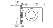
正極導電部材17はその一部にヒューズ部30を有する。正極導電部材17は、板状の部材で構成されており、正極端子15に接続する第1領域17Aと、この第1領域17Aから正極端子15と反対側に延出する第2領域17Bを有している。ここで、第2領域17Bの厚みは、第1領域17Aの厚みよりも厚くなっている。そして、第1領域17Aには、他の正極導電部材17の領域よりも電気抵抗が大きいヒューズ部30が形成されている。ヒューズ部30は、正極導電部材17の他の部位よりも断面積の小さい部位で構成されている。本実施形態では、ヒューズ部30は、正極導電部材17の一部に、その厚み方向に延びる孔30aを設けることによって構成されている。また、第2領域17Bには、例えば、二次電池1を複数個配列して組電池を構成したとき、各二次電池1の端子同士を接合するための外部導電部材(バスバー)が接合される。なお、正極端子15に接続する第1領域17Aと、この第1領域17Aから正極端子15と反対側に延出する第2領域17Bが同じ厚みとなるようにしてもよい。正極導電部材17は金属製であることが好ましく、例えばアルミニウムあるいはアルミニウム合金製とすることができる。
The positive electrode
本実施形態における二次電池1は、電極体10が収納された外装体20の外部にヒューズ部30を設けた二次電池において、ヒューズ部30が、カバー部材31で覆われていることを特徴とする。また、少なくともヒューズ部30を構成する正極導電部材17と封口体21との間に、絶縁部材32が設けられていることを特徴とする。
The
二次電池1に短絡が発生して過大な短絡電流が流れたとき、ヒューズ部30が溶断されるが、ヒューズ部30が溶断した後に、アークが飛散する。ヒューズ部30は、外装体20の外部に設けられているため、例えば近くに回路基板等の部品が配置されていると、アークの飛散によって部品が損傷するおそれがある。しかしながら、本実施形態においては、ヒューズ部30がカバー部材31で覆われているため、このようなアークの飛散による部品の破損を防止することができる。なお、カバー部材31は樹脂製部材であることが好ましく、電気絶縁性の樹脂製部材であることがより好ましい。カバー部材31は、電気絶縁性であれば樹脂製以外の部材を用いることもできる。また、カバー部材31が非常に大きな電気抵抗を有する部材とすることも可能であるが、電気絶縁性であることが好ましい。
When a short circuit occurs in the
本実施形態においては、正極導電部材17と封口体21の間に、絶縁部材32が配置されている。したがって、短絡電流が流れヒューズ部30が溶断し、第2領域17Bと正極端子15が電気的に切断された後、第2領域17Bと正極端子15が封口体21を介して電気的に接続された状態となることを確実に防止できる。
In the present embodiment, the insulating
また、本実施形態では、導電部材17を封口体21に対して垂直な方向から見たとき、ヒューズ部30は封口体21と重なる領域に設けられている。したがって、ヒューズ部30の下方には封口体21が配置されるため、ヒューズ部30が溶断した際、アークが飛散するこすることを防止できる。なお、封口体21においてヒューズ部30と対向する部分の厚みは、外装体20の側壁の厚みよりも大きいことが好ましい。また、ヒューズ部30と封口体21の間には絶縁部材32ないしカバー部材31の一部が配置されることがより好ましい。
Further, in the present embodiment, when the
また、本実施形態におけるヒューズ部30は、正極端子15の近傍に設けられている。そのため、正極端子15の上端部を正極導電部材17にかしめた際、正極導電部材17は、厚み方向に撓みが生じる恐れがある。もし、ヒューズ部30が、特許文献1に開示されているような、正極導電部材17の厚みが薄くなった部位で構成されていると、正極端子15をかしめた際に、ヒューズ部30が損傷するおそれがある。例えば、正極導電部材17の厚みが薄くなった部位を境に、正極導電部材17が折れ曲がるように変形する恐れがある。
Further, the
しかしながら、本実施形態においてヒューズ部30は、正極導電部材17に設けられた正極導電部材17の厚み方向に延びる孔である。このため、正極端子15の上端部を正極導電部材17にかしめた場合でも、ヒューズ部30が損傷するのを防止することができる。
However, in the present embodiment, the
また、本実施形態では、封口体21の長手方向において、ヒューズ部30よりも一方側に第1領域17Aが設けられ、ヒューズ部30よりも他方側に第2領域17Bが設けられている。そして、第2領域17Bの厚みが、第1領域17Aの厚みよりも厚くなっている。これにより、次のような効果が得られる。
Further, in the present embodiment, the
第2領域17Bに外部導電部材(バスバー)等の部材を溶接接続する際、第2領域17Bにおいて局部的に加熱される部分が生じる。そして、第2領域17B内における温度差により、第2領域17Bが撓むように変形する恐れがある。このような第2領域17Bの撓みにより、ヒューズ部30に負荷が加わり、ヒューズ部30が損傷したり、あるいは変形したりする恐れがある。本実施形態においては、第2領域17Bの厚み大きくすることにより、第2領域17Bに外部導電部材(バスバー)等の部材を溶接接続した場合であっても、溶接時に発生する熱により第2領域17Bが撓むように変形することを確実に防止できる。なお、このような効果は、ヒューズ部30がカバー部材31により覆われていない場合でも得られる。但し、ヒューズ部30がカバー部材31により覆われ、且つカバー部材31がヒューズ部30に接するように配置される場合、ヒューズ部30の損傷をより確実に防止できる。
When welding and connecting a member such as an external conductive member (bus bar) to the
また、正極端子15は、正極導電部材17において厚みの薄い第1領域17Aに接続されている。したがって、振動や衝撃等により正極導電部材17に負荷が加わった際に正極端子15が変形し、正極端子15近傍の密閉性が低下することを抑制できる。
The
なお、第2領域17Bの厚みは、第1領域17Aの厚みに対して、1.2〜5倍であることが好ましく、1.5〜4倍であることが好ましく、2〜4倍であることが更に好ましい。
The thickness of the
ヒューズ部30は、本実施形態にように、第2領域17Bよりも厚みの薄い領域、例えば、第1領域17Aと同等の厚みを有する領域に形成されることが好ましい。これにより、電気抵抗の大きい部位を容易に形成することができる。また、第1領域17Aは、正極端子15側に設けられているため、ヒューズ部30を、正極端子15近傍に形成することができる。これにより、ヒューズ部30を封口体21と正極端子15の固定部の近傍に配置することができるため、振動や衝撃等による負荷がヒューズ部30に加わり難くなる。また、これにより、正極端子15をかしめる際のヒューズ部30に加わる応力を小さくすることができ、ヒューズ部30の損傷を防止することができる。
The
本実施形態では、絶縁部材32は、正極導電部材17と封口体21とが対向する領域に配設されている。また、封口体21は、正極導電部材17に向かって突出する突起部21bを有している。一方、絶縁部材32は、突起部21bを挿入する挿入孔32aを有している。そして、突起部21bは、絶縁部材32の挿入孔32a内に挿入されて、正極導電部材17と接するように配置されている。これにより、正極導電部材17と封口体21が電気的に接続されている。また、上述の構成に加え、正極導電部材17が絶縁部材32に接続されているため、正極導電部材17に、封口体21に対して回転する方向の力が作用しても、正極導電部材17の位置ずれを防止することができる。
In the present embodiment, the insulating
なお、正極導電部材17と封口体21とが直接接する必要はなく、他の導電部材を介して電気的に接続されるようにしてもよい。また、正極導電部材17の下面に突起を設け、この突起を封口体21に接触させるようにしてもよい。
The positive electrode
また、本実施形態において、絶縁部材32は、正極導電部材17の第2領域17Bの上面よりも上方に延出した延出部32bを備えている。これにより、第2領域17Bに外部導電部材(バスバー)を溶接する際、延出部32bを基準に、外部導電部材(バスバー)の位置決めを容易に行うことができる。
In addition, in the present embodiment, the insulating
本実施形態において、図2の(b)に示すように、正極端子15の上端部が、正極導電部材17の第2領域17Bの上面よりも下方に位置する。これにより、正極導電部材17の第2領域17Bに外部導電部材(バスバー)等を接続する際等に、正極端子15に他の部材や製造装置が接触し、正極端子15近傍の部材が損傷し、正極端子15近傍における密閉性が低下することを確実に防止できる。
In the present embodiment, as shown in FIG. 2B, the upper end portion of the
本実施形態において、図2の(b)に示すように、正極導電部材17において、貫通孔21aの周囲には凹部が形成されている。そして、正極端子15は当該凹部内においてかしめられている。これにより、正極端子15の上端部の位置をより低い位置とすることができるため好ましい。なお、正極端子15のカシメ部と正極導電部材17において貫通孔21aの周囲に設けられた凹部の縁部をレーザ溶接等により溶接することがより好ましい。
In the present embodiment, as shown in FIG. 2B, in the positive electrode
本実施形態において、図2の(b)に示すように、絶縁部材32は正極導電部材17に固定される固定部を有する。これにより、絶縁部材32と正極導電部材17が確実に固定され、振動衝撃等の負荷がかかり絶縁部材32が損傷することを防止できる。当該固定部は、正極導電部材17の側面及び上面に接するようには位置される。当該固定部としては、爪形状とし、固定部を正極導電部材17に嵌合させるようにすることができる。なお、正極導電部材17の第2領域17Bの端部に薄肉部を設け、絶縁部材32の固定部を、第2領域17Bの端部に設けた薄肉部に嵌合させるようにしてもよい。
In the present embodiment, as shown in FIG. 2B, the insulating
本実施形態では、封口体21の突起部21bが正極導電部材17と接する。ここで、封口体21の突起部21bと正極導電部材17の接触面積を調整し、短絡電流が流れたとき、封口体21の突起部21bと正極導電部材17の接続部が溶融することが好ましい。そして、ヒューズ部30が溶断した後、封口体21の突起部21bと正極導電部材17が溶接接続され、確実にバイパスが形成されることが好ましい。
In this embodiment, the
封口体21は、正極導電部材17に向かって突出する突起部21bを有している。一方、絶縁部材32は、突起部21bを挿入する挿入孔32aを有している。そして、突起部21bは、絶縁部材32の挿入孔32a内に挿入されて、正極導電部材17と接するように配置されている。これにより、絶縁部材32および絶縁部材32に固定されている正極導電部材17は、封口体21の面方向に対して固定され、回転止めの効果が得られる
図2の(b)に示すように、正極導電部材17において封口体21との接続部とヒューズ部30の距離が、正極導電部材17におけるヒューズ部30と貫通孔17aの距離よりも大きいことが好ましい。
The sealing
図2の(b)に示すように、正極導電部材17における第1領域17Aの下面と、正極導電部材17における第2領域17Bの下面と同一面上に配置されることが好ましい。これにより正極導電部材17における第1領域17Aの下面と、正極導電部材17における第2領域17Bの下面とを同一面上で保持できるため、ヒューズ部30にかかる負荷を抑制することができる。
As shown in FIG. 2B, the lower surface of the
本実施形態に示すように、カバー部はヒューズ部30に接するように配置されることが好ましい。これにより、ヒューズ部30をより確実に補強することが可能となる。
As shown in the present embodiment, it is preferable that the cover part is arranged so as to be in contact with the
封口体21の長手方向において、正極導電部材17の封口体21の中央側の端部から、封口体21の長手方向における正極導電部材17の長さに対して40〜60%の位置にヒューズ部30が形成されていることが好ましい。これにより、正極導電部材17に正極端子15及び外部導電部材(バスバー)をバランスよく接続できることが可能となる。
In the longitudinal direction of the sealing
正極導電部材17の第2領域17Bは、厚み方向の全体において同一材料からなることが好ましい。特に、正極導電部材17の第2領域17Bは、厚み方向の全体がアルミニウム又はアルミニウム合金からなることが好ましい。
The
また、外部導電部材(バスバー)において、正極導電部材17の第2領域17Bに接続される部分及び封口体21において正極導電部材17の第2領域17Bは、アルミニウム又はアルミニウム合金からなることが好ましい。これにより、各部材間の接続状態が良好な状態となるため、ヒューズ部30が溶断した後、外部導電部材(バスバー)―正極導電部材17の第2領域17B―封口体21の電気抵抗がより低減できる。
Further, in the external conductive member (bus bar), the portion connected to the
正極導電部材17の第2領域17Bの上面に突起を設けることができる。これにより、第2領域17Bに外部導電部材(バスバー)を溶接する際、第2領域17Bの上面に設けた突起を基準に、外部導電部材(バスバー)の位置決めを容易に行うことができる。外部導電部材(バスバー)に開口又は切り欠きを設け、当該開口又は切り欠きの内部に第2領域17Bの上面に設けた突起を配置することができる。
A protrusion can be provided on the upper surface of the
本発明において、カバー部材31と絶縁部材32とは、同一部材で構成されていてもよい。このとき、正極導電部材17と、カバー部材31及び絶縁部材32は、一体的に構成されていることが好ましい。正極導電部材17と、カバー部材31及び絶縁部材32との一体的な構成は、例えば、インサート成形を用いて形成することができる。
In the present invention, the
図3(a)、(b)、及び図4を参照しながら、正極導電部材17と、カバー部材31及び絶縁部材32とを、インサート成形を用いて形成する方法を説明する。
A method of forming the positive electrode
まず、正極導電部材17を、図3(a)、(b)に示すような形状に加工する。ここで、図3(a)は、加工された正極導電部材17の上面図、図3(b)は、その断面図である。図3(a)、(b)に示すように、板状の正極導電部材17をプレス加工によって、正極端子15に接続する第1領域17Aと、第1領域17Aから正極端子15と反対側に延出する第2領域17Bとを形成する。このとき、第2領域17Bの厚みは、第1領域17Aの厚みよりも厚く加工される。そして、第1領域17Aに、ヒューズ部30を構成する孔30aと、正極端子15が貫通する貫通孔17aとを形成する。
First, the positive electrode
次に、正極導電部材17を、所定形状の金型(不図示)に装着した後、この金型の空間に溶融樹脂を注入することによって、図4に示すように、正極導電部材17と、カバー部材31及び絶縁部材32とを、インサート成形する。
Next, after mounting the positive electrode
このように、正極導電部材17と、カバー部材31及び絶縁部材32とを、インサート成形により一体的に形成することによって、ヒューズ部30の強度を向上させることができる。これにより、正極導電部材17に負荷が加わった場合であっても、ヒューズ部30が損傷することを防止できる。
By thus integrally forming the positive electrode
例えば、二次電池1に強い衝撃や振動が加わったとき、ヒューズ部30に負荷が加わる恐れがある。あるいは、二次電池1が厚み方向において膨張した場合、正極導電部材17において、外部導電部材(バスバー)が接続される部分と、正極端子15が接続される部分とでは、水平方向においてそれぞれ反対側に負荷が加わる恐れがある。このような場合、ヒューズ部30に負荷が加わる。
For example, when a strong shock or vibration is applied to the
また、正極端子15が正極導電部材17にかしめにより接続された場合、正極端子15をかしめた際、ヒューズ部30が損傷するのを防止することができる。また、正極導電部材17と、カバー部材31及び絶縁部材32とを、部品として一体化することにより、二次電池1の組み立て工程を簡素化することができる。
Moreover, when the
図5は、図1(a)、(b)に示した二次電池1の負極端子16近傍を拡大して示した部分拡大断面図である。なお、負極端子16近傍の構成は、ヒューズ部が形成されていない代わりに、短絡機構が形成されている点で、正極端子15近傍の構成と異なる。
FIG. 5 is a partially enlarged cross-sectional view showing the vicinity of the
図5に示すように、負極端子16は、封口体21に設けられた貫通孔を貫通して封口体21に固定されている。また、負極端子16と封口体21との間は、ガスケット40により密封されている。負極端子16は、封口体21の内部側において、負極集電体14に接続されている。また、負極端子16は、封口体21の外部側において、負極導電部材18と接続されている。また、封口体21と負極導電部材18とは、絶縁部材41によって電気的に絶縁されている。また、封口体21と負極集電体14とは、絶縁部材42によって電気的に絶縁されている。
As shown in FIG. 5, the
負極導電部材18は銅又は銅合金からなることが好ましい。また、負極導電部材18が銅又は銅合金からなる領域と、アルミニウムまたはアルミニウム合金からなる領域を有し、銅又は銅合金からなる領域に負極端子16を接続し、アルミニウムまたはアルミニウム合金からなる領域にアルミニウムまたはアルミニウム合金からなる外部導電部材(バスバー)を接続することもできる。負極導電部材18をアルミニウムまたはアルミニウム合金製とし、負極端子16において負極導電部材18と接続される部分をアルミニウムまたはアルミニウム合金製とすることもできる。
The negative electrode
図5に示すように、封口体21の一部には、空洞部44が形成され、この空洞部44を覆うように可変部材としての反転プレート43が配置されている。なお、当該部分の形成方法としては、封口体21に短絡機構用の貫通孔を設け、反転プレート43を封口体21に接続し、反転プレート43で短絡機構用の貫通孔を密閉するようにすればよい。あるいは、封口体21をプレス加工し、可変部材としての反転プレート43を形成してもよい。
As shown in FIG. 5, a
ここで、封口体21は、図2(a)に示したように、突起部21bが正極導電部材17と電気的に接続されているため、反転プレート43は、封口体21と同一の極性を有する。従って、二次電池1が過充電状態になって、外装体20の内部の圧力が設定値以上になったとき、反転プレート43は反転して、負極導電部材18と接触する。これにより、反転プレート43は、正極板と負極板とを電極体の外部で電気的に短絡させる短絡機構として作用する。
Here, in the sealing
なお、可変部材の形状は反転プレート43の形状に限定されず、外装体20の内圧が設定値以上となったとき変形し、負極導電部材18と電気的に接続されるような形状であればよい。可変部材は金属製であることが好ましく、封口体21と同じ金属からなることが好ましい。
The shape of the variable member is not limited to the shape of the
短絡機構が作動すると、封口体21を電流経路として、正極端子15と負極端子16間に短絡電流が流れる。その結果、正極導電部材17に設けたヒューズ部30が短絡電流により溶断されるため、二次電池1の過充電の進行を防止することができる。
When the short-circuit mechanism operates, a short-circuit current flows between the
以上、本発明を好適な実施形態により説明してきたが、こうした記述は限定事項ではなく、もちろん、種々の改変が可能である。 Although the present invention has been described above with reference to the preferred embodiment, such description is not a limitation and, of course, various modifications can be made.
例えば、上記実施形態では、カバー部材31と絶縁部材32とを、同一部材で一体的に形成した例を説明したが、図6(a)、(b)に示すように、カバー部材31及び絶縁部材32を、別部材で形成しても勿論構わない。この場合、カバー部材31は、ヒューズ部30を覆うように形成される。カバー部材31は、例えば、溶融した樹脂を塗布して形成することができる。あるいは、カバー部材31をヒューズ部30に嵌合固定してもよい。あるいは。樹脂製部材からなるカバー部材31を接着剤等で貼り付けてもよい。あるいは、ヒューズ部30の外面に電気絶縁性のテープを貼り付けてもよい。また、本発明におけるカバー部材31及び絶縁部材32は、その材料は特に限定されない。また、図2(a)では、突起部21bを、正極導電部材17の第2領域17Bにおいて、幅方向に沿って帯状に形成したが、図6(a)に示したように、円筒状に形成してもよい。
For example, in the above-described embodiment, an example in which the
なお、カバー部材31に、正極導電部材17の第2領域17Bの上面よりも上方に延出した延出部を設けることもできる。第2領域17Bに外部導電部材(バスバー)を溶接する際、カバー部材31に設けた延出部を基準に、外部導電部材(バスバー)の位置決めを容易に行うことができる。
It should be noted that the
カバー部材31は樹脂材料からなることが好ましい。例えば、PFA(テトラフルオロエチレン・パーフルオロアルキルビニルエーテル共重合体)、PPS(ポリフェニレンスルファイド)、PC(ポリカーボネート)等を用いることができる。特にカバー部材31は耐熱性の樹脂材料からなることが好ましい。耐熱性の樹脂材料としては、PFA(テトラフルオロエチレン・パーフルオロアルキルビニルエーテル共重合体)、PPS(ポリフェニレンスルファイド)等を用いることが好ましい。
The
絶縁部材32は電気絶縁性の樹脂材料からなることが好ましい。例えば、PFA、PPS、PC(ポリカーボネート)等を用いることが好ましい。
The insulating
また、上記実施形態では、ヒューズ部30を、正極導電部材17の一部に、その厚み方向に延びる孔30aを設けることによって形成して例を説明したが、これに限定されず、正極導電部材17の一部が、他の正極導電部材17の部位よりも断面積が小さくなった構成であれば、その構造は特に限定されない。例えば、図7に示すように、正極導電部材17の一部に、厚み方向に延びる孔30aを設けるとともに、孔30aに対して、正極導電部材17の幅方向の両端部に、スリット30bを設けて、ヒューズ部30を形成してもよい。
In the above embodiment, the
また、上記実施形態では、短絡機構として、反転プレート43を例に説明したが、これに限定されず、外装体20の内部の圧力が設定値以上になったとき作動して、正極板と負極板とを電気的に短絡させる機能を有するものであればよい。例えば二次電池1の通常使用時、封口体21は正極及び負極のいずれとも電気的に接続されておらず、外装体20の内部の圧力が設定値以上となったとき、正極と封口体21が電気的に接続され、且つ負極と封口体21が電気的に接続されるような機構であってもよい。あるいは、外装体20の内部の圧力が設定値以上となったとき、封口体21を介さず、正極と負極が電気的に接続される機構であってもよい。
Further, although the reversing
上記実施形態では、正極導電部材17において、第1領域17Aの幅と第2領域17Bの幅が同じであったが、図8に示すように、第2領域17Bの幅を第1領域17Aの幅よりも大きくしてもよい。ここで、第1領域17Aの幅、第2領域17Bの幅とは、封口体21の短手方向の幅である。このような構成であると、封口体21の長手方向における第2領域17Bの長さを長くすることなく、第2領域17Bとバスバー(外部導電部材)の接続面あるいは接続部を大きくすることができる。このような構成は、角形の電池ケースにおいて、最小面積の面に正極端子15及び負極端子16が配置される場合、特に効果的である。
In the above embodiment, in the positive electrode
また、上記実施形態では、封口体21の長手方向において、正極導電部材17の第1領域17Aが、第2領域17Bよりも外側に配置されている。しかしながら、封口体21の長手方向において、正極導電部材17の第1領域17Aが、第2領域17Bよりも内側に配置される構成とすることができる。このような構成であれば、第2領域17Bにバスバー(外部導電部材)を溶接接続する場合、溶融した金属粒子(スパッタ)が封口体21の中央部に形成される排出弁25上に飛散し、排出弁25が損傷することを防止できる。このような構成は、角形の電池ケースにおいて、最小面積の面に正極端子15及び負極端子16が配置される場合、特に効果的である。
Moreover, in the above-described embodiment, the
角形の電池ケースにおいて、最小面積の面に正極端子15及び負極端子16が配置される場合、注液孔を封止する封止部材24がブラインドリベット等のように、溶接等を用いず封止部材を変形させることにより封止することが好ましい。
When the
角形の電池ケースにおいて、最小面積の面に正極端子15及び負極端子16が配置される場合、注液孔と絶縁部材32の距離が小さくなる。そのため、注液孔を封止するために、封止部材24を封口体21にレーザ溶接等で溶接接続した場合、溶接の際に生じる熱により絶縁部材32が損傷する恐れがある。したがって、封止部材24がブラインドリベット等のように、溶接等を用いず封止部材を変形させることにより封止するものであることが好ましい。
In the prismatic battery case, when the
また、上記実施形態では、正極導電部材17の一部にヒューズ部30を設けた例を説明したが、負極導電部材18の一部にヒューズ部30を設けても構わない。
Further, in the above-described embodiment, an example in which the
また、本発明における二次電池1は、その種類は特に限定されない。また、電極体10も、その構造は特に限定されない。長尺状の正極板と長尺状の負極板とをセパレータを介して巻回した巻回電極体であっても良い。また、複数枚の正極板と複数枚の負極板とをセパレータを介して積層した積層型電極体であってもよい。
The type of the
なお、本発明は、非水電解質二次電池に用いた場合特に有効である。正極、負極、セパレータ、電解液等については公知の材料を使用できる。正極ないし電解液に、二次電池1が過充電状態となった際にガスを発生される材料、例えば炭酸リチウムやシクロヘキシルベンゼン等が添加されていることが特に好ましい。
The present invention is particularly effective when used in a non-aqueous electrolyte secondary battery. Known materials can be used for the positive electrode, the negative electrode, the separator, the electrolytic solution, and the like. It is particularly preferable to add to the positive electrode or the electrolytic solution a material that generates gas when the
また、本発明における二次電池1を、複数個配列して組電池を構成することもでき。図9は、本発明における二次電池1を6個配列して、組電池50を構成した例を示した斜視図である。図9に示すように、各二次電池1の正極端子15及び負極端子16の位置を、交互に入れ替えて配列し、隣り合う二次電池1の正極端子15と負極端子16とを、バスバー(外部導電部材)60で接合することによって、6個の二次電池1が電気的に直列に接続されている。勿論、6個の二次電池1が電気的に並列に接続されていても構わない。
Further, a plurality of
組電池50において、正極端子15及び負極端子16等が配置される面の上方に回路基板が配置される場合、本発明は特に効果的である。
In the assembled
なお、バスバー(外部導電部材)60において正極導電部材17上に配置される部分の封口体21の長手方向における幅は、正極導電部材17の第2領域17Bの封口体21の長手方向における長さよりも小さいことが好ましい。
The width of the portion of the bus bar (external conductive member) 60 arranged on the positive electrode
1 二次電池
10 電極体
11 正極芯体露出部
12 負極芯体露出部
13 正極集電体
14 負極集電体
15 正極端子
16 負極端子
17 正極導電部材
17A 第1領域
17B 第2領域
17a 貫通孔
18 負極導電部材
20 外装体
21 封口体
21a 貫通孔
21b 突起部
22 ガスケット
23 絶縁部材
24 封止部材
25 排出弁
30 ヒューズ部
30a 孔
30b スリット
31 カバー部材
32 絶縁部材
32a 挿入孔
32b 延出部
40 ガスケット
41、42 絶縁部材
43 反転プレート
44 空洞部
50 組電池
1 secondary battery
10 electrode body
11 Positive electrode core exposed part
12 Negative electrode core exposed part
13 Positive electrode collector
14 Negative electrode current collector
15 Positive terminal
16 Negative electrode terminal
17 Positive electrode conductive member
17A First area
17B Second area
17a through hole
18 Negative electrode conductive member
20 exterior body
21 Sealed body
21a through hole
21b Projection
22 Gasket
23 Insulation member
24 Sealing member
25 discharge valve
30 fuse part
30a hole
30b slit
31 cover member
32 Insulation member
32a insertion hole
32b extension part
40 gasket
41, 42 Insulation member
43 Inversion plate
44 Cavity
50 battery pack
Claims (13)
開口部を有し、前記電極体を収納する外装体と、
前記開口部を封口する封口体と、
前記正極板又は前記負極板に接続され、前記封口体に設けられた貫通孔を貫通する端子と、
前記封口体の外部側において、前記端子に接続された導電部材と、
を備え、
前記導電部材は、ヒューズ部を有し、
前記ヒューズ部は、カバー部材により覆われており、
前記導電部材と前記封口体との間に、絶縁部材が配置されており、
前記導電部材は、前記ヒューズ部よりも一方側に第1領域を有し、前記ヒューズ部よりも他方側に第2領域を有し、
前記第2領域の厚みは、前記第1領域の厚みよりも厚く、
前記導電部材は、前記第1領域において前記端子に接続されており、
前記第2領域は、外部導電部材を接合する部位となる領域である二次電池。 An electrode body including a positive electrode plate and a negative electrode plate,
An exterior body having an opening and containing the electrode body,
A sealing body for sealing the opening,
A terminal connected to the positive electrode plate or the negative electrode plate and penetrating a through hole provided in the sealing body;
On the outer side of the sealing body, a conductive member connected to the terminal,
Equipped with
The conductive member has a fuse portion,
The fuse portion is covered with a cover member,
An insulating member is arranged between the conductive member and the sealing body ,
The conductive member has a first region on one side of the fuse part and a second region on the other side of the fuse part,
The thickness of the second region is thicker than the thickness of the first region,
The conductive member is connected to the terminal in the first region,
The second region is a secondary battery, which is a region to be a part to which an external conductive member is joined .
前記正極端子及び前記負極端子はそれぞれ前記封口体に取り付けられており、
前記端子は、前記正極端子又は前記負極端子であり、
前記導電部材を前記封口体に対して垂直な方向から見たとき、前記ヒューズ部は前記封口体と重なる領域に設けられている請求項1に記載の二次電池。 A positive electrode terminal electrically connected to the positive electrode plate, and a negative electrode terminal electrically connected to the negative electrode plate,
The positive electrode terminal and the negative electrode terminal are respectively attached to the sealing body,
The terminal is the positive electrode terminal or the negative electrode terminal,
The secondary battery according to claim 1, wherein the fuse portion is provided in a region overlapping with the sealing body when the conductive member is viewed from a direction perpendicular to the sealing body.
前記短絡機構の作動により、前記ヒューズ部に短絡電流が流れ、前記ヒューズ部が溶断する、請求項1〜5の何れかに記載の二次電池。 Further comprising a short-circuit mechanism that operates when the pressure inside the exterior body reaches or exceeds a set value and electrically short-circuits the positive electrode plate and the negative electrode plate outside the electrode body,
The operation of the short mechanism, short-circuit current flows in the fuse portion, said fuse portion is blown, the secondary battery according to any one of claims 1-5.
前記封口体は、前記導電部材に向かって突出する突起部を有し、
前記絶縁部材は、挿入孔を有し、
前記突起部は、前記絶縁部材の挿入孔内に配置されて、前記導電部材と電気的に接続されている、請求項1〜6の何れかに記載の二次電池。 The insulating member is arranged in a region where the conductive member and the sealing body face each other,
The sealing body has a protrusion protruding toward the conductive member,
The insulating member has an insertion hole,
The protrusion, the disposed in the insertion hole of the insulating member, the conductive member and are electrically connected, the secondary battery according to any one of claims 1-6.
開口部を有し、前記電極体を収納する外装体と、
前記開口部を封口する封口体と、
前記正極板又は前記負極板に接続され、前記封口体に設けられた貫通孔を貫通する端子と、
前記封口体の外部側において、前記端子に接続された導電部材と、を備え、
前記導電部材は、ヒューズ部を有し、
前記ヒューズ部は、カバー部材により覆われており、
前記導電部材と前記封口体との間に、絶縁部材が配置されており、
前記絶縁部材は、前記導電部材と前記封口体とが対向する領域に配設されており、
前記封口体は、前記導電部材に向かって突出する突起部を有し、
前記絶縁部材は、挿入孔を有し、
前記突起部は、前記絶縁部材の挿入孔内に配置されて、前記導電部材と電気的に接続されている二次電池。 An electrode body including a positive electrode plate and a negative electrode plate,
An exterior body having an opening and containing the electrode body,
A sealing body for sealing the opening,
A terminal connected to the positive electrode plate or the negative electrode plate and penetrating a through hole provided in the sealing body;
On the outer side of the sealing body, comprising a conductive member connected to the terminal,
The conductive member has a fuse portion,
The fuse portion is covered with a cover member,
An insulating member is arranged between the conductive member and the sealing body ,
The insulating member is arranged in a region where the conductive member and the sealing body face each other,
The sealing body has a protrusion protruding toward the conductive member,
The insulating member has an insertion hole,
The secondary battery , wherein the protrusion is disposed in the insertion hole of the insulating member and electrically connected to the conductive member .
開口部を有し、前記電極体を収納する外装体と、
前記開口部を封口する封口体と、
前記正極板又は前記負極板に接続され、前記封口体に設けられた貫通孔を貫通する端子と、
前記封口体の外部側において、前記端子に接続された導電部材と、を備え、
前記導電部材は、ヒューズ部を有し、
前記ヒューズ部は、カバー部材により覆われており、
前記導電部材と前記封口体との間に、絶縁部材が配置されており、
前記導電部材は、前記ヒューズ部よりも一方側に第1領域を有し、前記ヒューズ部よりも他方側に第2領域を有し、
前記第2領域の厚みは、前記第1領域の厚みよりも厚く、
前記導電部材は、前記第1領域において前記端子に接続されており、
前記絶縁部材は、前記導電部材と前記封口体との間に設けられた部位から、前記導電部材の前記第2領域の上面よりも上方に延出した延出部を備えている二次電池。 An electrode body including a positive electrode plate and a negative electrode plate,
An exterior body having an opening and containing the electrode body,
A sealing body for sealing the opening,
A terminal connected to the positive electrode plate or the negative electrode plate and penetrating a through hole provided in the sealing body;
On the outer side of the sealing body, comprising a conductive member connected to the terminal,
The conductive member has a fuse portion,
The fuse portion is covered with a cover member,
An insulating member is arranged between the conductive member and the sealing body ,
The conductive member has a first region on one side of the fuse part and a second region on the other side of the fuse part,
The thickness of the second region is thicker than the thickness of the first region,
The conductive member is connected to the terminal in the first region,
The rechargeable battery according to claim 1, wherein the insulating member includes an extension portion that extends upward from a portion provided between the conductive member and the sealing body, above an upper surface of the second region of the conductive member .
開口部を有し、前記電極体を収納する外装体と、
前記開口部を封口する封口体と、
前記正極板又は前記負極板に接続され、前記封口体に設けられた貫通孔を貫通する端子と、
前記封口体の外部側において、前記端子に接続された導電部材と、を備え、
前記導電部材は、ヒューズ部を有し、
前記ヒューズ部は、カバー部材により覆われており、
前記導電部材と前記封口体との間に、絶縁部材が配置されており、
前記カバー部材は樹脂製部材であり、
前記導電部材と、前記樹脂製部材及び前記絶縁部材は、一体的に構成されており、
前記導電部材は、前記ヒューズ部において前記導電部材の厚み方向に延びる孔を有する、二次電池。 An electrode body including a positive electrode plate and a negative electrode plate,
An exterior body having an opening and containing the electrode body,
A sealing body for sealing the opening,
A terminal connected to the positive electrode plate or the negative electrode plate and penetrating a through hole provided in the sealing body;
On the outer side of the sealing body, comprising a conductive member connected to the terminal,
The conductive member has a fuse portion,
The fuse portion is covered with a cover member,
An insulating member is arranged between the conductive member and the sealing body ,
The cover member is a resin member,
The conductive member, the resin member and the insulating member are integrally configured,
The secondary battery , wherein the conductive member has a hole extending in the thickness direction of the conductive member in the fuse portion .
開口部を有し、前記電極体を収納する外装体と、
前記開口部を封口する封口体と、
前記正極板又は前記負極板に接続され、前記封口体に設けられた貫通孔を貫通する端子と、
前記封口体の外部側において、前記端子に接続された導電部材と、を備え、
前記導電部材は、ヒューズ部を有し、
前記ヒューズ部は、カバー部材により覆われており、
前記導電部材と前記封口体との間に、絶縁部材が配置されており、
前記導電部材は、前記ヒューズ部において前記導電部材の厚み方向に延びる孔を有し、
前記カバー部材の一部が前記導電部材の厚み方向に延びる孔内に配置された、二次電池。
An electrode body including a positive electrode plate and a negative electrode plate,
An exterior body having an opening and containing the electrode body,
A sealing body for sealing the opening,
A terminal that is connected to the positive electrode plate or the negative electrode plate and penetrates a through hole provided in the sealing body,
On the outer side of the sealing body, a conductive member connected to the terminal,
The conductive member has a fuse portion,
The fuse portion is covered with a cover member,
An insulating member is arranged between the conductive member and the sealing body ,
The conductive member has a hole extending in the thickness direction of the conductive member in the fuse portion,
A secondary battery in which a part of the cover member is arranged in a hole extending in the thickness direction of the conductive member .
Priority Applications (3)
| Application Number | Priority Date | Filing Date | Title |
|---|---|---|---|
| JP2016037888A JP6707367B2 (en) | 2016-02-29 | 2016-02-29 | Secondary battery and battery pack |
| CN201710065507.9A CN107134559B (en) | 2016-02-29 | 2017-02-06 | Secondary battery and battery pack |
| US15/431,185 US10411244B2 (en) | 2016-02-29 | 2017-02-13 | Secondary battery and assembled battery |
Applications Claiming Priority (1)
| Application Number | Priority Date | Filing Date | Title |
|---|---|---|---|
| JP2016037888A JP6707367B2 (en) | 2016-02-29 | 2016-02-29 | Secondary battery and battery pack |
Publications (2)
| Publication Number | Publication Date |
|---|---|
| JP2017157334A JP2017157334A (en) | 2017-09-07 |
| JP6707367B2 true JP6707367B2 (en) | 2020-06-10 |
Family
ID=59679869
Family Applications (1)
| Application Number | Title | Priority Date | Filing Date |
|---|---|---|---|
| JP2016037888A Active JP6707367B2 (en) | 2016-02-29 | 2016-02-29 | Secondary battery and battery pack |
Country Status (3)
| Country | Link |
|---|---|
| US (1) | US10411244B2 (en) |
| JP (1) | JP6707367B2 (en) |
| CN (1) | CN107134559B (en) |
Families Citing this family (19)
| Publication number | Priority date | Publication date | Assignee | Title |
|---|---|---|---|---|
| KR20180126934A (en) * | 2017-05-19 | 2018-11-28 | 삼성에스디아이 주식회사 | Secondary Battery |
| CN109285974B (en) * | 2017-07-20 | 2021-08-03 | 宁德时代新能源科技股份有限公司 | Secondary cell top cap subassembly and secondary cell |
| JP6962167B2 (en) * | 2017-12-12 | 2021-11-05 | 三洋電機株式会社 | Rechargeable battery |
| JP7059623B2 (en) | 2017-12-26 | 2022-04-26 | トヨタ自動車株式会社 | Secondary battery |
| WO2019179206A1 (en) * | 2018-03-23 | 2019-09-26 | Chongqing Jinkang New Energy Vehicle Co., Ltd. | Battery cell for an electric vehicle battery pack |
| WO2019181285A1 (en) * | 2018-03-23 | 2019-09-26 | 三洋電機株式会社 | Secondary battery |
| KR102179991B1 (en) * | 2018-12-21 | 2020-11-17 | 한국단자공업 주식회사 | Series connecting apparatus for battery module |
| US11942657B2 (en) | 2019-05-24 | 2024-03-26 | Autonetworks Technologies, Ltd. | Inter-terminal connection structure |
| JPWO2021060008A1 (en) * | 2019-09-26 | 2021-04-01 | ||
| CN113054295B (en) * | 2019-12-26 | 2022-08-09 | 比亚迪股份有限公司 | Cover plate assembly, battery module, power battery pack and electric automobile |
| CN113302785B (en) * | 2020-04-30 | 2022-05-10 | 宁德时代新能源科技股份有限公司 | End cap assembly, secondary battery, battery pack, and power consumption device |
| CN213752969U (en) * | 2020-04-30 | 2021-07-20 | 中航锂电(洛阳)有限公司 | Battery, battery module and battery pack |
| DE102020118843A1 (en) | 2020-07-16 | 2022-01-20 | Bayerische Motoren Werke Aktiengesellschaft | Battery cell with an electrical fuse |
| CN112421187B (en) * | 2020-11-20 | 2022-04-08 | 合肥国轩高科动力能源有限公司 | Soft connecting sheet capable of improving safety performance of lithium ion battery |
| JP7414701B2 (en) | 2020-12-03 | 2024-01-16 | プライムプラネットエナジー&ソリューションズ株式会社 | Secondary batteries and assembled batteries |
| KR102602260B1 (en) * | 2021-03-23 | 2023-11-14 | 주식회사 유앤에스에너지 | Current collector for electrodes |
| JP7412454B2 (en) * | 2021-03-31 | 2024-01-12 | 寧徳時代新能源科技股▲分▼有限公司 | Bus components, batteries and power consumption equipment |
| DE102021109628A1 (en) * | 2021-04-16 | 2022-10-20 | Bayerische Motoren Werke Aktiengesellschaft | Battery cell with an electrical fuse |
| CN217468606U (en) * | 2022-07-01 | 2022-09-20 | 宁德时代新能源科技股份有限公司 | End cover assembly, battery monomer, battery and consumer |
Family Cites Families (16)
| Publication number | Priority date | Publication date | Assignee | Title |
|---|---|---|---|---|
| US7747856B2 (en) * | 2002-07-26 | 2010-06-29 | Computer Associates Think, Inc. | Session ticket authentication scheme |
| WO2010084054A1 (en) * | 2009-01-23 | 2010-07-29 | Evonik Oxeno Gmbh | Polyolefin gas phase polymerization with 3-substituted c4-10-alkene |
| KR101126839B1 (en) * | 2010-06-04 | 2012-03-23 | 에스비리모티브 주식회사 | Secondary battery |
| JP5656592B2 (en) | 2010-12-06 | 2015-01-21 | 日立オートモティブシステムズ株式会社 | Secondary battery |
| US9023498B2 (en) * | 2011-07-07 | 2015-05-05 | Samsung Sdi Co., Ltd. | Rechargeable battery |
| US9970696B2 (en) * | 2011-07-20 | 2018-05-15 | Thermo King Corporation | Defrost for transcritical vapor compression system |
| US8469435B2 (en) * | 2011-08-05 | 2013-06-25 | Failed Levees Applications, LLC | Truck payload storage enclosure |
| US9172079B2 (en) * | 2012-02-01 | 2015-10-27 | Samsung Sdi Co., Ltd. | Rechargeable battery |
| KR20130139446A (en) * | 2012-06-07 | 2013-12-23 | 삼성에스디아이 주식회사 | Secondary battery |
| EP2924761B1 (en) * | 2012-11-26 | 2018-06-13 | Hitachi Automotive Systems, Ltd. | Rectangular secondary battery |
| JP5885036B2 (en) * | 2013-01-24 | 2016-03-15 | トヨタ自動車株式会社 | battery |
| KR20140125657A (en) * | 2013-04-19 | 2014-10-29 | 삼성에스디아이 주식회사 | Rechargeable battery |
| KR101696010B1 (en) | 2013-06-19 | 2017-01-12 | 삼성에스디아이 주식회사 | Rechargeable battery |
| KR102272264B1 (en) * | 2014-01-20 | 2021-07-02 | 삼성에스디아이 주식회사 | Battery module having short connecting part |
| JP6620407B2 (en) * | 2015-03-06 | 2019-12-18 | 株式会社Gsユアサ | Electricity storage element |
| CN204991821U (en) * | 2015-09-09 | 2016-01-20 | 丰田自动车株式会社 | Secondary battery |
-
2016
- 2016-02-29 JP JP2016037888A patent/JP6707367B2/en active Active
-
2017
- 2017-02-06 CN CN201710065507.9A patent/CN107134559B/en active Active
- 2017-02-13 US US15/431,185 patent/US10411244B2/en active Active
Also Published As
| Publication number | Publication date |
|---|---|
| US10411244B2 (en) | 2019-09-10 |
| CN107134559B (en) | 2021-06-08 |
| JP2017157334A (en) | 2017-09-07 |
| US20170250394A1 (en) | 2017-08-31 |
| CN107134559A (en) | 2017-09-05 |
Similar Documents
| Publication | Publication Date | Title |
|---|---|---|
| JP6707367B2 (en) | Secondary battery and battery pack | |
| JP6491817B2 (en) | Secondary battery | |
| JP7238083B2 (en) | secondary battery | |
| US9306205B2 (en) | Rechargeable battery having safety member | |
| JP2020107464A (en) | Secondary battery and battery pack | |
| CN105576184B (en) | Rechargeable battery | |
| JP5910888B2 (en) | Sealed battery | |
| US20150140410A1 (en) | Rechargeable battery having fuse | |
| JP2014157813A (en) | Battery module | |
| US10424809B2 (en) | Secondary battery, method for manufacturing same, and battery pack employing same | |
| EP3544078B1 (en) | Secondary battery | |
| JP7116811B2 (en) | Secondary battery and secondary battery assembly | |
| JP5691778B2 (en) | Nonaqueous electrolyte secondary battery | |
| US11152673B2 (en) | Secondary battery | |
| JP7297996B2 (en) | Secondary battery and secondary battery assembly | |
| KR100824896B1 (en) | Cylinderical Lithium Rechargeable Battery | |
| KR102371195B1 (en) | Rechargeable Mattery And Rechargeable battery Module Using The Same | |
| EP2775554A1 (en) | Rechargeable battery | |
| WO2021060006A1 (en) | Secondary battery | |
| CN109494395B (en) | Electricity storage device | |
| JP7304371B2 (en) | Terminal parts and secondary batteries | |
| KR100560514B1 (en) | Secondary battery |
Legal Events
| Date | Code | Title | Description |
|---|---|---|---|
| A521 | Request for written amendment filed |
Free format text: JAPANESE INTERMEDIATE CODE: A523 Effective date: 20170127 |
|
| A621 | Written request for application examination |
Free format text: JAPANESE INTERMEDIATE CODE: A621 Effective date: 20181107 |
|
| A977 | Report on retrieval |
Free format text: JAPANESE INTERMEDIATE CODE: A971007 Effective date: 20190918 |
|
| A131 | Notification of reasons for refusal |
Free format text: JAPANESE INTERMEDIATE CODE: A131 Effective date: 20191008 |
|
| A521 | Request for written amendment filed |
Free format text: JAPANESE INTERMEDIATE CODE: A523 Effective date: 20191120 |
|
| TRDD | Decision of grant or rejection written | ||
| A01 | Written decision to grant a patent or to grant a registration (utility model) |
Free format text: JAPANESE INTERMEDIATE CODE: A01 Effective date: 20200421 |
|
| A61 | First payment of annual fees (during grant procedure) |
Free format text: JAPANESE INTERMEDIATE CODE: A61 Effective date: 20200520 |
|
| R150 | Certificate of patent or registration of utility model |
Ref document number: 6707367 Country of ref document: JP Free format text: JAPANESE INTERMEDIATE CODE: R150 |