[1.パチンコ機の全体構造]
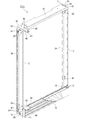
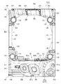
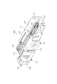
以下、図面を参照して本発明の好適な実施形態について、図面を参照して説明する。まず、図1乃至図7を参照して実施形態に係るパチンコ機の全体について説明する。図1は実施形態に係るパチンコ機の外枠に対して本体枠を開放し、本体枠に対して扉枠を開放した状態を示す斜視図であり、図2はパチンコ機の正面図であり、図3はパチンコ機の側面図であり、図4はパチンコ機の平面図であり、図5はパチンコ機の背面図であり、図6はパチンコ機を構成する外枠、本体枠、遊技盤、扉枠の後方から見た分解斜視図であり、図7はパチンコ機を構成する外枠、本体枠、遊技盤、扉枠の前方から見た分解斜視図である。
[1. Overall structure of pachinko machine]
Hereinafter, preferred embodiments of the present invention will be described with reference to the drawings. First, the entire pachinko machine according to the embodiment will be described with reference to FIGS. 1 to 7. 1 is a perspective view showing a state in which a main body frame is opened with respect to an outer frame of a pachinko machine according to an embodiment and a door frame is opened with respect to the main body frame, and FIG. 2 is a front view of the pachinko machine, 3 is a side view of the pachinko machine, FIG. 4 is a plan view of the pachinko machine, FIG. 5 is a rear view of the pachinko machine, and FIG. FIG. 7 is an exploded perspective view seen from the rear of the door frame, and FIG. 7 is an exploded perspective view seen from the front of the outer frame, the main body frame, the game board, and the door frame configuring the pachinko machine.
図1乃至図7に示すように、本実施形態に係るパチンコ機1は、遊技ホールの島(図示しない)に設置される外枠2と、外枠2に開閉自在に軸支され且つ遊技盤4を装着し得る本体枠3と、本体枠3に開閉自在に軸支され且つ遊技盤4に形成されて球が打ち込まれる遊技領域605を遊技者が視認し得る遊技窓101とその遊技窓101の下方に配置され且つ遊技の結果によって払出される球を貯留する貯留皿としての皿ユニット300とを備えた扉枠5と、を備えて構成されている。
As shown in FIG. 1 to FIG. 7, a pachinko machine 1 according to the present embodiment has an outer frame 2 installed on an island (not shown) of a game hall, and an openable and closably pivotally supported outer frame 2 and a game board. 4, a main body frame 3 to which the player can mount 4, a game window 101 in which the player can visually recognize a game area 605 which is rotatably supported by the main body frame 3 and is formed on the game board 4 and into which a ball is driven, and the game window 101. And a door frame 5 provided with a plate unit 300 as a storage plate for storing balls to be paid out depending on the result of the game.
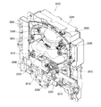
外枠2には、その下方前方に装飾カバー板15を補強するカバー補強金具14が固着されている。また、本体枠3には、上記したように遊技盤4が着脱自在に装着し得る他に、その裏面下部に打球発射装置650(図5参照)と、遊技盤4を除く扉枠5や本体枠3に設けられる電気的部品を制御するための各種の制御基板や電源基板等が一纏めに設けられている基板ユニット1100が取付けられ、本体枠3の後面開口580(図6を参照)を覆うカバー体1250が着脱自在に設けられている。更に、扉枠5には、上記した皿ユニット300の他に、遊技窓101を閉塞するようにガラスユニット450と、ハンドル装置400とが設けられている。なお、扉枠5と本体枠3とが正面から見て略同じ方形の大きさであり、正面から本体枠3が視認できないようになっている。以下、パチンコ機1を構成する部材について詳細に説明する。
A cover reinforcing metal member 14 for reinforcing the decorative cover plate 15 is fixed to the outer frame 2 at the lower front thereof. In addition to the game board 4 which can be detachably attached to the main body frame 3 as described above, a hitting ball launching device 650 (see FIG. 5) is provided on the lower rear surface thereof, and the door frame 5 and the main body other than the game board 4 are attached. A board unit 1100, on which various control boards and power boards for controlling electrical parts provided in the frame 3 are collectively provided, is attached to cover a rear surface opening 580 (see FIG. 6) of the body frame 3. The cover body 1250 is detachably provided. Further, in addition to the dish unit 300 described above, the door frame 5 is provided with a glass unit 450 and a handle device 400 so as to close the game window 101. The door frame 5 and the main body frame 3 have substantially the same rectangular size when viewed from the front, and the main body frame 3 cannot be visually recognized from the front. Hereinafter, members constituting the pachinko machine 1 will be described in detail.
[1−1.外枠]
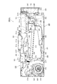
外枠2について、主として図8乃至図16を参照して説明する。図8は、外枠2の正面斜視図であり、図9は、同外枠2の正面から見た分解斜視図であり、図10は、同外枠2の正面図であり、図11は、同外枠2の背面図であり、図12は、図10のB−B断面図(A)と図12(A)のC−C断面図(B)、D−D断面図(C)、E−E断面図(D)である。また、図13は本体枠の上軸支金具と外枠の上支持金具との脱着構造を説明するための斜視図であり、図14は外枠の上支持金具の裏面に設けられるロック部材の取付状態を示す分解斜視図(A)と下方から見た斜視図(B)である。更に、図15は軸支ピンとロック部材との関係を説明するための上支持金具部分の裏面図であり、図16はロック部材の作用を説明するための上支持金具部分の裏面図である。
[1-1. Outer frame]
The outer frame 2 will be described mainly with reference to FIGS. 8 to 16. 8 is a front perspective view of the outer frame 2, FIG. 9 is an exploded perspective view of the outer frame 2 seen from the front, FIG. 10 is a front view of the outer frame 2, and FIG. 12 is a rear view of the outer frame 2, and FIG. 12 is a sectional view taken along the line BB of FIG. 10 (A), a sectional view taken along the line CC of FIG. 12A, and a sectional view taken along the line DD. , EE sectional drawing (D). FIG. 13 is a perspective view for explaining a structure for attaching and detaching the upper shaft support fitting of the main body frame and the upper support fitting of the outer frame, and FIG. 14 shows a lock member provided on the back surface of the upper support fitting of the outer frame. It is the exploded perspective view (A) which shows a mounting state, and the perspective view (B) seen from the lower part. Further, FIG. 15 is a rear view of the upper support fitting part for explaining the relationship between the shaft support pin and the lock member, and FIG. 16 is a rear view of the upper support fitting part for explaining the operation of the lock member.
図8及び図9に示すように、本実施形態に係る外枠2は、横方向へ延びる上下の上枠板10及び下枠板11と、縦(上下)方向へ延びる左右の側枠板12,13とを、夫々の端部を連結するための連結部材19で連結することによって方形状に組み付けられている。具体的には、連結部材19は、中央と左右とに段差のある表彰台状に形成され、突出した中央の部分が上枠板10及び下枠板11の両端部中央に形成された係合切欠部20に嵌合され、一段下がった左右の部分の平面に上枠板10の裏面と下枠板11の上面とが当接し且つ一段下がった左右の部分の一側面に側枠板12,13の内側面が当接するようになっている。
As shown in FIGS. 8 and 9, the outer frame 2 according to the present embodiment includes upper and lower upper frame plates 10 and lower frame plates 11 extending in the horizontal direction, and left and right side frame plates 12 extending in the vertical (vertical) direction. , 13 are connected to each other by a connecting member 19 for connecting the respective end portions, so that they are assembled in a rectangular shape. Specifically, the connecting member 19 is formed in a podium shape having a step between the center and the left and right, and the protruding central portion is an engagement notch formed at the center of both end portions of the upper frame plate 10 and the lower frame plate 11. The rear surface of the upper frame plate 10 and the upper surface of the lower frame plate 11 are in contact with the flat surfaces of the left and right portions which are fitted to the portion 20, and the side frame plates 12, 13 are attached to one side surface of the left and right portions which are lowered one step. The inner surface of the abuts against.
そして、その状態で、上枠板10の係合切欠部20の両側方及び下枠板11の係合切欠部20の両側方に夫々形成される挿通穴21と連結部材19の一段下がった左右の部分の平面に形成される複数(図示の場合2個)の連結穴22(図9の上枠板10と側枠板12とを連結する連結部材19に表示するが、他の連結部材19にも存在する)とを一致させて上方又は下方から複数(図示の場合2本)の連結ビス23で止着し、更に、側枠板12,13の上下端部分に穿設される複数(図示の場合2個)の取付穴24と連結部材19の一段下がった左右の部分の側面に形成される複数(図示の場合3個)の連結穴25とを一致させて側方外側から複数(図示の場合3本)の連結ビス26,27で止着することにより、上下の上枠板10及び下枠板11と左右の側枠板12,13とが強固に連結固定される。ただし、3本の連結ビス26,27のうち、1本の連結ビス27は、側枠板12,13と連結部材19とを連結するものではなく、上枠板10及び下枠板11と連結部材19とを側方から直接連結するものである。
Then, in this state, the insertion holes 21 formed on both sides of the engaging cutout portion 20 of the upper frame plate 10 and both sides of the engaging cutout portion 20 of the lower frame plate 11 and the left and right of which the connecting member 19 is lowered by one step. A plurality of (two in the illustrated case) connecting holes 22 formed in the plane of the portion (indicated on the connecting member 19 connecting the upper frame plate 10 and the side frame plate 12 in FIG. 9), but other connecting members 19 (There are also present in the above), and are fixed by a plurality (two in the case shown) of connecting screws 23 from above or below, and a plurality of ( A plurality of (from the side in the figure) mounting holes 24 and a plurality of (three in the figure) connecting holes 25 formed on the side surfaces of the left and right portions of the connecting member 19 which are lowered by one step are aligned from the outer side. The upper and lower upper and lower frame plates 10 and 11 and the left and right side frame plates 12 and 13 are firmly connected and fixed by fastening with the connecting screws 26 and 27 (three in the figure). However, one of the three connecting screws 26 and 27 does not connect the side frame plates 12 and 13 to the connecting member 19, but connects the upper frame plate 10 and the lower frame plate 11. The member 19 is directly connected from the side.
外枠2を構成する上枠板10と下枠板11、及び側枠板12,13のうち、上枠板10と下枠板11とは従来と同じ木製であり、側枠板12,13は、軽量金属、例えば、アルミニュウム合金の押出し成型板により構成されている。上枠板10及び下枠板11を従来と同じ木製で構成した理由は、パチンコ機1を遊技場に列設される島に設置する場合に、島の垂直面に対し所定の角度をつけて固定する作業を行う必要があるが、そのような作業は上枠板10及び下枠板11と島とに釘を打ち付けて行われるため、釘を打ち易くするためである。一方、側枠板12,13をアルミニュウム合金の押出し成型板により構成した理由は、従来の木製に比べ強度を維持しつつ肉厚を薄く形成することができるため、側枠板12,13の内側に隣接する本体枠3の側面壁540〜543(図69を参照)の正面から見たときの左右幅を広くすることができる。このため左右方向の寸法の大きな遊技盤4を本体枠3に装着することができることになり、結果的に遊技盤4の遊技領域605を大きく形成することができるからである。
Among the upper frame plate 10 and the lower frame plate 11, and the side frame plates 12 and 13 that form the outer frame 2, the upper frame plate 10 and the lower frame plate 11 are made of the same wood as the conventional one, and the side frame plates 12 and 13 are the same. Is made of a light-weight metal, for example, an extruded plate of aluminum alloy. The reason why the upper frame plate 10 and the lower frame plate 11 are made of the same wood as the conventional one is that when the pachinko machine 1 is installed on an island lined up in a game arcade, a predetermined angle is formed with respect to the vertical plane of the island. It is necessary to perform a fixing work, but such a work is performed by striking nails on the upper frame plate 10 and the lower frame plate 11 and the island, so that it is easy to strike the nails. On the other hand, the reason why the side frame plates 12 and 13 are made of extruded aluminum alloy plates is that the thickness of the side frame plates 12 and 13 can be reduced while maintaining strength compared to conventional wood. The lateral widths of the side walls 540 to 543 (see FIG. 69) of the main body frame 3 adjacent to each other when viewed from the front can be widened. Therefore, the game board 4 having a large lateral dimension can be mounted on the main body frame 3, and as a result, the game area 605 of the game board 4 can be formed large.
なお、側枠板12,13をアルミニュウム合金の平板で構成すると、充分な剛性が確保できないため、図12(C)に示すように、側枠板12(側枠板13も全く同じ構造である。)の後方部分内側にリブによって後方が開放した空間部28(側枠板13の空間部28は図11に表示)を形成して後方部分の肉厚h1が厚くなるように引き抜き成型されている。もちろん、この肉厚h1は、従来の木製の肉厚と同等若しくは若干薄い寸法となっている。
If the side frame plates 12 and 13 are made of aluminum alloy flat plates, sufficient rigidity cannot be ensured. Therefore, as shown in FIG. .) is formed inside by a rib to open the rear side (the space portion 28 of the side frame plate 13 is shown in FIG. 11) and is drawn and molded so that the thickness h1 of the rear portion becomes thicker. There is. Of course, this wall thickness h1 is the same as or slightly thinner than the wall thickness of the conventional wood.
また、図12(B),(D)に示すように、側枠板12の空間部28の前方には、連結部材19の一段下がった左右の部分の一方の部分が嵌め込まれる溝部29(側枠板13の溝部29は図8に表示)が形成されている。側枠板12の溝部29から前端部までは、図12(B)〜(D)に示すように、その内側面が連結部材19の一段下がった左右の部分の他方の部分が当接する平板状をなすものであるが、その平板部に材料軽減のための浅い凹部が形成されている。更に、溝部29が形成される反対側の面(外側面)には、図8及び図12(B)に示すように、上支持金具45の垂下片部53が挿入される凹部30(側枠板13の凹部30は図9に表示)が形成されている。
Further, as shown in FIGS. 12B and 12D, in front of the space portion 28 of the side frame plate 12, one portion of the left and right portions of the connecting member 19 with one step lowered is fitted into the groove portion 29 (side). The groove portion 29 of the frame plate 13 is formed with a mark (shown in FIG. 8). As shown in FIGS. 12(B) to 12(D), the groove portion 29 of the side frame plate 12 has a flat plate shape whose inner side surface is in contact with the other portion of the left and right portions of the connecting member 19 lowered by one step. However, a shallow concave portion for reducing material is formed in the flat plate portion. Further, as shown in FIG. 8 and FIG. 12B, a concave portion 30 (side frame) into which the hanging piece portion 53 of the upper support fitting 45 is inserted is formed on the opposite surface (outer surface) where the groove portion 29 is formed. The recess 30 of the plate 13 is formed with a mark (shown in FIG. 9).
そして、上記のように形成される軸支側の側枠板12には、連結部材19を取付けるための構成以外に、その上部に上支持金具45の垂下片部53を側枠板12の外側に止着ビス32で止着するための取付穴31が穿設されると共に、その下部に下支持金具66の垂直当接片72に形成される取付穴69と一致させて止着ビス34で止着するための取付穴33が穿設されている。また、取付穴33の下部であって側枠板12の前方部分に側枠板12とカバー補強金具14とを止着ビス36で止着するための取付穴35が形成されている。
In addition to the structure for attaching the connecting member 19, the hanging piece portion 53 of the upper support metal fitting 45 is provided on the upper side of the side frame plate 12 on the shaft support side formed as described above outside the side frame plate 12. A mounting hole 31 for fastening with a fastening screw 32 is formed in the lower portion of the lower support fitting 66, and a mounting hole 69 formed in the vertical abutment piece 72 of the lower support metal fitting 66 is formed in the lower portion of the mounting hole 31. A mounting hole 33 for fastening is provided. Further, a mounting hole 35 for fixing the side frame plate 12 and the cover reinforcing metal fitting 14 with a fixing screw 36 is formed in the lower part of the mounting hole 33 and in the front part of the side frame plate 12.
一方、開放側の側枠部13には、連結部材19を取付けるための構成以外に、その上部に閉鎖用突起38を取付ネジ39で取付けるための取付穴37が穿設され、その下部に閉鎖用突起41を取付ネジ42で取付けるための取付穴40が穿設されると共に、さらに最下方に側枠板13とカバー補強金具14とを止着ビス44で止着するための取付穴43が形成されている。
On the other hand, in addition to the structure for mounting the connecting member 19, the side frame portion 13 on the open side is provided with a mounting hole 37 for mounting a closing projection 38 with a mounting screw 39 on the upper portion thereof, and for closing the lower portion thereof. A mounting hole 40 for mounting the projection 41 for mounting with a mounting screw 42 is formed, and a mounting hole 43 for mounting the side frame plate 13 and the cover reinforcing metal fitting 14 with a mounting screw 44 is further provided at the lowermost position. Has been formed.
なお、この閉鎖用突起38,41は、外枠2に対して本体枠3を閉じる際に、本体枠3の開放側辺に沿って取付けられる錠装置1000のフック部1054,1065(図121を参照)と係合するものであり、後に詳述するように錠装置1000のシリンダ錠1010に鍵を差し込んで一方に回動することにより、フック部1054,1065と閉鎖用突起38,41との係合が外れて本体枠3を外枠2に対して開放することができるものである。
The closing projections 38 and 41 are hook portions 1054 and 1065 (see FIG. 121) of the locking device 1000 attached along the open side of the body frame 3 when closing the body frame 3 with respect to the outer frame 2. As described in detail later, by inserting a key into the cylinder lock 1010 of the locking device 1000 and rotating it to one side, the hook portions 1054 and 1065 and the closing projections 38 and 41 are engaged with each other. The engagement is released and the main body frame 3 can be opened with respect to the outer frame 2.
また、下枠板11と左右の側枠板12,13の下部前面に固定されるカバー補強金具14は、閉止時においてその上面に本体枠3が載置されるものであり、カバー補強金具14の表面及び側面は、装飾カバー板15によって被覆されている。なお、外枠2の装飾カバー板15の開放側の上面には、本体枠3の閉止時に本体枠3をスムーズに案内するための案内板18が交換可能に装着されている。
Further, the cover reinforcing metal fittings 14 fixed to the lower front surfaces of the lower frame plate 11 and the left and right side frame plates 12, 13 are such that the main body frame 3 is placed on the upper surface thereof when the cover reinforcing metal fittings 14 are closed. The surface and the side surface of the are covered with the decorative cover plate 15. A guide plate 18 for smoothly guiding the main body frame 3 when the main body frame 3 is closed is replaceably mounted on the upper surface of the outer frame 2 on the open side of the decorative cover plate 15.
ところで、本体枠3を開閉自在に軸支する構造として、上枠板10と側枠板12とを連結する機能も兼用する上支持金具45とカバー補強金具14の一側上面に沿って取付けられる下支持金具66とが設けられている。上支持金具45には、前方に突出している支持突出片46に支持突出片46の側方から先端中央部に向かって屈曲して形成された支持鉤穴47が形成されており、この支持鉤穴47に本体枠3の後述する上軸支金具503の軸支ピン504(図71を参照)が着脱自在に係合されるようになっている。
By the way, as a structure in which the main body frame 3 is pivotally supported so as to be openable and closable, it is attached along one side upper surface of the upper support metal fitting 45 and the cover reinforcing metal fitting 14 which also have a function of connecting the upper frame board 10 and the side frame board 12. A lower support fitting 66 is provided. In the upper support fitting 45, a support hook hole 47 formed by bending from a side of the support projection piece 46 toward a central portion of the tip is formed in a support projection piece 46 projecting forward, and this support hook is formed. A shaft support pin 504 (see FIG. 71) of an upper shaft support fitting 503 of the body frame 3 described later is detachably engaged with the hole 47.
また、下支持金具66も前方に突出した形状に形成されているが、この突出した部分に上向きに支持突起68が突設され、この支持突起68に本体枠3の後述する枠支持板506(図72を参照)に形成される支持穴が挿入される。したがって、外枠2に本体枠3を支持するためには、下支持金具66の支持突起68に本体枠3の枠支持板506に形成される支持穴を係合させた後、本体枠3の上軸支金具503の軸支ピン504を支持鉤穴47に掛け止めることにより簡単に開閉自在に軸支することができる。
Further, the lower support metal fitting 66 is also formed in a shape projecting forward, and a projecting projection 68 is projected upward on this projecting portion, and a frame supporting plate 506 (described later) of the main body frame 3 is formed on the projecting projection 68. The support hole formed in FIG. 72) is inserted. Therefore, in order to support the main body frame 3 on the outer frame 2, after the support holes formed on the frame support plate 506 of the main body frame 3 are engaged with the support protrusions 68 of the lower support fitting 66, By suspending the shaft support pin 504 of the upper shaft support metal fitting 503 to the support hook hole 47, the shaft support can be easily opened and closed.
また、上支持金具45は、上枠板10の軸支側の上面及び前面に凹状に形成される取付段部49に装着されるものであるが、その装着に際し、上支持金具45に形成される複数(図示の場合2個)の取付穴48と取付段部49に穿設される複数(図示の場合2個)の取付穴50とを一致させて取付ビス51を上方から差し込み、上枠板10の裏面から押し当てられる挟持板52に止着することにより上支持金具45が上枠板10に堅固に固定される。
Further, the upper support metal fitting 45 is mounted on the mounting step portion 49 formed in a concave shape on the upper surface and the front surface of the upper frame plate 10 on the shaft support side. A plurality of (two in the case shown) mounting holes 48 and a plurality (two in the case shown) mounting holes 50 formed in the mounting step portion 49 are aligned, and the mounting screws 51 are inserted from above to form an upper frame. The upper support fitting 45 is firmly fixed to the upper frame plate 10 by being fixed to the holding plate 52 pressed from the back surface of the plate 10.
また、上支持金具45の外側側方には、側枠板12の外側に当接する垂下片部53があり、その垂下片部53にも取付穴が穿設され、この取付穴と取付穴31とを止着ビス32で止着することにより、上支持金具45と側枠板12とを固定すると共に、上枠板10と側枠板12とを上支持金具45を介して連結している。
Further, on the outer side of the upper support metal fitting 45, there is a hanging piece portion 53 that comes into contact with the outside of the side frame plate 12, and a mounting hole is also formed in the hanging piece portion 53. The upper support fitting 45 and the side frame plate 12 are fixed by fastening the and the fixing screws 32 together, and the upper frame plate 10 and the side frame plate 12 are connected via the upper support fitting 45. ..
一方、下支持金具66は、前述したように側枠板12の取付穴33と垂直当接片72の取付穴69とを一致させた状態で止着ビス34で止着し、さらに、下支持金具66の水平面の中程に穿設される取付穴70に取付ネジ71を差し込むことにより、装飾カバー板15を介してカバー補強金具14の上面に止着されるものである。
On the other hand, the lower support fitting 66 is fixed with the fixing screw 34 in a state where the mounting hole 33 of the side frame plate 12 and the mounting hole 69 of the vertical abutment piece 72 are aligned with each other, as described above. By inserting a mounting screw 71 into a mounting hole 70 formed in the middle of a horizontal surface of the metal fitting 66, the metal fitting 66 is fixed to the upper surface of the cover reinforcing metal fitting 14 via the decorative cover plate 15.
上記のように構成される外枠2において、その構成部材である上枠板10と下枠板11と側枠板12,13とを連結部材19で連結することにより、連結部材19が側枠板12,13の内面に密着して止着されると共に連結部材19と上枠板10及び下枠板11が係合した状態で止着されるので、その組み付け強度が高く頑丈な方形状の枠組みとすることができる。上記した連結部材19と上枠板10及び下枠板11との係合状態に加え、連結部材19の側枠板12,13への取付けに際し、溝部29に連結部材19の一段下がった左右の部分の一方の部分が嵌め込まれる構造であるため、連結部材19の側枠板12,13への取付けが強固となり、これによっても方形状の枠組みの強度を向上することができると共にその位置決めを正確に行うことができる。
In the outer frame 2 configured as described above, the upper frame plate 10, the lower frame plate 11, and the side frame plates 12 and 13, which are the components thereof, are connected by the connecting member 19, so that the connecting member 19 is a side frame. Since it is firmly attached to the inner surfaces of the plates 12 and 13 and the connection member 19 and the upper frame plate 10 and the lower frame plate 11 are engaged with each other, the mounting strength is high and the shape of the square is strong. It can be a framework. In addition to the above-described engagement state of the connecting member 19 with the upper frame plate 10 and the lower frame plate 11, when attaching the connecting member 19 to the side frame plates 12 and 13, the left and right of the connecting member 19 lowered one step in the groove portion 29. Since one part of the parts is fitted, the connection member 19 is firmly attached to the side frame plates 12 and 13, which also improves the strength of the rectangular frame and accurately positions it. Can be done.
また、連結部材19によって上枠板10、下枠板11、側枠板12,13を連結した後、上支持金具45を所定の位置に取付けたときに、図10及び図11に示すように、各枠板10,11,12,13の外側面(外周面)から外側に突出する部材は存在しないので、パチンコ機1を図示しないパチンコ島台に設置する際に、隣接する装置(例えば、隣接する玉貸器)と密着して取付けることができる。また、下支持金具66を取付けたときにも、カバー補強金具14の上面と下支持金具66の上面とが略同一平面となるようになっている。
When the upper frame plate 10, the lower frame plate 11, and the side frame plates 12 and 13 are connected by the connecting member 19 and then the upper support fitting 45 is attached to a predetermined position, as shown in FIGS. Since there is no member that projects outward from the outer surface (outer peripheral surface) of each frame plate 10, 11, 12, 13, when installing the pachinko machine 1 on a pachinko island stand (not shown), an adjacent device (for example, It can be attached closely to the adjacent ball lender. Further, even when the lower support fitting 66 is attached, the upper surface of the cover reinforcing fitting 14 and the upper surface of the lower support fitting 66 are substantially flush with each other.
ところで、本体枠3を開閉自在に軸支するための上支持金具45の裏面には、図14に示すようにロック部材80が回動自在に軸支されている。より詳細に説明すると、図14(A)に示すように、上支持金具45の支持突出片46は、先端部が円弧状の平板として形成されると共に支持突出片46の外側縁に沿って直角に折り曲げられた垂下壁46aが形成される。この垂下壁46aにより、上支持金具45の支持突出片46の強度を向上させることができると共に、正面から見たときに次に説明するロック部材80が視認できないようにして外観を良くし、更に、次に説明するロック部材80の弾性片80cの先端当接部が当接する部位として利用したりロック部材80が支持突出片46から外側に飛び出さないように停止部として利用している。また、支持突出片46に形成される支持鉤穴47は、垂下壁46aが形成されない反対側の側方から内側にやや向ってさらに先端中央部に向かって傾斜状となるように屈曲して形成されている。そして、支持鉤穴47の傾斜状穴部の溝寸法は、軸支ピン504の直径よりもやや大きな寸法に形成されている。
By the way, as shown in FIG. 14, a lock member 80 is rotatably supported on the back surface of the upper support fitting 45 for rotatably supporting the body frame 3. More specifically, as shown in FIG. 14(A), the support protrusion piece 46 of the upper support metal fitting 45 is formed as a flat plate having an arcuate tip and is perpendicular to the outer edge of the support protrusion piece 46. A drooping wall 46a that is bent to form is formed. The hanging wall 46a can improve the strength of the support protruding piece 46 of the upper support fitting 45, and make the lock member 80, which will be described below, invisible when viewed from the front, to improve the appearance, and The elastic member 80c of the lock member 80, which will be described next, is used as a portion where the distal end contact portion of the elastic member 80c abuts, and as a stop portion so that the lock member 80 does not jump out from the supporting protrusion 46. Further, the support hook hole 47 formed in the support projecting piece 46 is formed by bending so as to be inclined inward from the side on the opposite side where the hanging wall 46a is not formed, toward the inside, and further toward the center of the tip. Has been done. The groove size of the inclined hole portion of the support hook hole 47 is formed to be slightly larger than the diameter of the shaft support pin 504.
また、上記した垂下壁46aは、支持鉤穴47の前方の入口端部から支持突出片46及び上支持金具45の外側縁に沿って直角に折り曲げられて形成されていると共に、支持鉤穴47の前方の入口端部の部分で内側に向って折り曲げられて停止垂下部47aとなっている。また、支持突出片46の略中央に取付穴46bが穿設され、取付穴46bにロック部材80がリベット81によって回転自在に軸支されている。ロック部材80は、合成樹脂によって成型されるものであり、ストッパー部80aと操作部80bとがL字状に形成され、また操作部80bと反対側に円弧状の弾性片80cが一体的に延設されている。そして、ストッパー部80aと操作部80bとがなすL字状の基部にリベット81が挿通される取付穴80dが形成されている。しかして、ロック部材80がリベット81によって取付穴46bに取付けられて支持突出片46の裏面に回転自在に固定した状態においては、図14(B)に示すように、弾性片80cの先端当接部が垂下壁46aの内側面と当接しており、ストッパー部80aが支持鉤穴47の傾斜状穴部を閉塞するようになっている。また、このときストッパー部80aの先端部分は、支持鉤穴47の傾斜状穴部の先頭空間部分を閉塞した状態となっていない。即ち、通常の状態で支持鉤穴47の先頭空間部分には、本体枠3の上軸支金具503の軸支ピン504が挿入される空間が形成されている。
Further, the hanging wall 46a is formed by bending the support hook piece 47 from the front inlet end portion of the support hook hole 47 along the outer edges of the support projecting piece 46 and the upper support metal fitting 45 at a right angle. Is bent inward at the inlet end portion in front of to form a stop hanging portion 47a. Further, a mounting hole 46b is bored substantially in the center of the support projecting piece 46, and a lock member 80 is rotatably supported by a rivet 81 in the mounting hole 46b. The lock member 80 is molded of synthetic resin, and the stopper portion 80a and the operating portion 80b are formed in an L shape, and the arc-shaped elastic piece 80c is integrally extended on the side opposite to the operating portion 80b. It is set up. Further, a mounting hole 80d into which the rivet 81 is inserted is formed in an L-shaped base portion formed by the stopper portion 80a and the operating portion 80b. Then, in the state in which the lock member 80 is attached to the attachment hole 46b by the rivet 81 and is rotatably fixed to the back surface of the support protrusion piece 46, as shown in FIG. The portion is in contact with the inner side surface of the hanging wall 46a, and the stopper portion 80a closes the inclined hole portion of the support hook hole 47. At this time, the tip portion of the stopper portion 80a is not in a state of closing the leading space portion of the inclined hole portion of the support hook hole 47. That is, in a normal state, a space into which the shaft support pin 504 of the upper shaft support metal fitting 503 of the main body frame 3 is inserted is formed in the leading space portion of the support hook hole 47.
ところで、軸支ピン504が支持鉤穴47の傾斜状穴部の先端空間部分に挿入されてストッパー部80aの先端側方が入口端部の停止垂下部47aに対向している状態(この状態ではストッパー部80aの先端側方と停止垂下部47aとの間に僅かな隙間があり当接した状態となっていない)である通常の軸支状態においては、屈曲して形成される支持鉤穴47の傾斜状穴部の先端空間部分に位置する軸支ピン504とストッパー部80aの先端面80eとの夫々の中心が斜め方向にずれて対向した状態となっている。そして、この通常の軸支状態においては、重量のある本体枠3を軸支している軸支ピン504が支持鉤穴47の先端部分に当接した状態となっているので、軸支ピン504からストッパー部80aの先端面80eへの負荷がほとんどかかっていないため、ロック部材80の弾性片80cに対し負荷がかかっていない状態となっている。また、図15(A)に示すように、ストッパー部80aの先端面80eが操作部80bを操作して回動したときにロック部材80がスムーズに回動するように円弧状に形成されている。図示の場合、この円弧状先端面80eの円弧中心は、リベット81の中心(ロック部材80の回転中心)である。
By the way, a state in which the shaft support pin 504 is inserted into the distal end space portion of the inclined hole portion of the support hook hole 47 and the lateral side of the distal end of the stopper portion 80a faces the stop hanging portion 47a at the inlet end portion (in this state, In a normal shaft support state in which there is a slight gap between the side of the tip of the stopper portion 80a and the stop hanging portion 47a, and the state is not in contact, the supporting hook hole 47 formed by bending. The centers of the shaft support pin 504 located in the tip space portion of the inclined hole portion and the tip end surface 80e of the stopper portion 80a are diagonally displaced and face each other. In this normal shaft support state, the shaft support pin 504, which supports the heavy body frame 3, is in contact with the tip portion of the support hook hole 47, so that the shaft support pin 504 is provided. Since almost no load is applied to the tip end surface 80e of the stopper portion 80a from the above, the elastic piece 80c of the lock member 80 is not loaded. Further, as shown in FIG. 15(A), the tip end surface 80e of the stopper portion 80a is formed in an arc shape so that the lock member 80 can be smoothly rotated when it is rotated by operating the operation portion 80b. .. In the illustrated case, the arc center of the arcuate tip surface 80e is the center of the rivet 81 (the rotation center of the lock member 80).
このため、軸支ピン504が支持鉤穴47の傾斜状穴部の傾斜に沿って抜ける方向に作用力Fがかかって円弧状の先端面80eに当接したとき、その作用力Fを、軸支ピン504と円弧状の先端面80eとの当接部分に作用する分力F1(円弧状先端面80eの円弧の法線方向)と、軸支ピン504と支持鉤穴47の傾斜状穴部の一側内面との当接部分に作用する分力F2と、に分けたときに、分力F1の方向がリベット81の中心(ロック部材80の回転中心)を向くため、ロック部材80のストッパー部80aの先端部が支持突出片46から外れる方向(図示の時計方向)に回転させるモーメントが働かず、軸支ピン504がロック部材80のストッパー部80aの先端部と支持鉤穴47の傾斜状穴部の一側内面との間に挟持された状態を保持する。このため、通常の軸支状態でもあるいは軸支ピン504の作用力がロック部材80にかかった状態でも、ロック部材80の弾性片80cに常時負荷がかからず、合成樹脂で一体形成される弾性片80cのクリープによる塑性変形を防止し、長期間に亘って軸支ピン504の支持鉤穴47からの脱落を防止することができる。なお、仮に無理な力がかかってロック部材80のストッパー部80aの先端部が支持突出片46から外れる方向(図示の時計方向)に回転させられても、ストッパー部80aの先端部の一側方が停止垂下部47aに当接してそれ以上外れる方向に回転しないので、ロック部材80が支持突出片46の外側にはみ出ることはない。
Therefore, when the axial support pin 504 acts on the arcuate tip surface 80e in the direction in which the axial support pin 504 comes out along the inclination of the inclined hole portion of the support hook hole 47, the acting force F is Component force F1 acting on the contact portion between the support pin 504 and the arcuate tip surface 80e (the normal direction of the arc of the arcuate tip surface 80e), and the inclined hole portion of the shaft support pin 504 and the support hook hole 47. When the force is divided into the component force F2 acting on the abutting portion with the inner surface of one side, the direction of the component force F1 is directed to the center of the rivet 81 (rotation center of the lock member 80), so that the stopper of the lock member 80 is A moment for rotating the tip end of the portion 80a in a direction (clockwise direction in the drawing) that separates from the support protrusion 46 does not work, and the pivot pin 504 causes the tip of the stopper portion 80a of the lock member 80 and the inclined shape of the support hook hole 47. The state of being sandwiched between the inner surface on one side of the hole is maintained. Therefore, the elastic piece 80c of the lock member 80 is not always loaded even in the normal shaft support state or the state in which the acting force of the shaft support pin 504 is applied to the lock member 80, and the elastic member integrally formed of synthetic resin is used. It is possible to prevent plastic deformation of the piece 80c due to creep, and to prevent the shaft support pin 504 from falling out of the support hook hole 47 for a long period of time. Even if unreasonable force is applied to rotate the tip of the stopper portion 80a of the lock member 80 in a direction (clockwise in the drawing) away from the support protruding piece 46, one side of the tip portion of the stopper portion 80a is rotated. Contacts the stop hanging portion 47a and does not rotate in the direction of further disengagement, so that the lock member 80 does not protrude to the outside of the supporting projection piece 46.
また、図15(A)に示す実施形態においては、ストッパー部80aの円弧状先端面80eの円弧中心がリベット81の中心(ロック部材80の回転中心)であることにより、軸支ピン504に対し支持鉤穴47の傾斜状穴部の傾斜に沿って抜ける方向の作用力Fがかかってもロック部材80に回転モーメントが生じないものについて説明したが、図15(B)に示すように、ストッパー部80aの円弧状先端面80fの曲率半径をさらに小さくし、且つロック部材80のリベット81による軸支位置を支持突出片46の内側にした場合に、軸支ピン504が支持鉤穴47の傾斜状穴部の傾斜に沿って抜ける方向に作用力Fがかかって円弧状の先端面80fに当接したとき、その作用力Fを、軸支ピン504と円弧状の先端面80fとの当接部分に作用する分力F1(円弧状先端面80fの円弧の法線方向)と、軸支ピン504と支持鉤穴47の傾斜状穴部の一側内面との当接部分に作用する分力F2と、に分けた場合において、分力F1によって回転モーメントが働いてロック部材80を図示の矢印方向(時計回転方向)に回転させるが、ロック部材80が回転してもストッパー部80aの先端一側方が停止垂下部47aに当接するだけであるため、ロック部材80が支持突出片46の外側にはみ出ることもないし、ロック部材80の弾性片80cに対しても負荷がかかることもない。
Further, in the embodiment shown in FIG. 15A, since the arc center of the arcuate tip surface 80e of the stopper portion 80a is the center of the rivet 81 (rotation center of the lock member 80), Although it has been described that the lock member 80 does not generate the rotation moment even when the acting force F in the direction of exiting along the inclination of the inclined hole portion of the support hook hole 47 is applied, as shown in FIG. When the radius of curvature of the arcuate distal end surface 80f of the portion 80a is further reduced and the pivotal support position of the lock member 80 by the rivet 81 is inside the support protrusion piece 46, the pivot pin 504 tilts the support hook hole 47. When the acting force F is applied to the arcuate tip surface 80f in the direction of slipping out along the inclination of the circular hole portion, the acting force F is applied to the pivot pin 504 and the arcuate tip surface 80f. A component force F1 acting on a part (direction of a normal line of an arc of the arcuate tip surface 80f) and a component force acting on a contact part between the shaft support pin 504 and one inner surface of the inclined hole portion of the support hook hole 47. In the case of dividing into F2 and F2, the rotational moment acts by the component force F1 to rotate the lock member 80 in the direction of the arrow (clockwise rotation direction) shown in the figure, but even if the lock member 80 rotates, one end of the stopper portion 80a Since the side portion only abuts on the stop hanging portion 47a, the lock member 80 does not protrude to the outside of the support protrusion piece 46, and the elastic piece 80c of the lock member 80 is not loaded.
つまり、図15(A)及び図15(B)に示す実施形態から理解することができる点は、軸支ピン504が支持鉤穴47の傾斜状穴部の傾斜に沿って抜ける方向に作用力Fがかかって先端面80e,80fに当接したとき、その作用力Fの軸支ピン504と先端面80e,80fとの当接部分に作用する分力F1によってロック部材80を回転させる回転モーメントが生じない位置若しくはロック部材80をその先端部が支持突出片46の外側に向って回転させる回転モーメントが生ずる位置にロック部材80の回転中心(リベット81により固定される軸)を位置させることにより、常時ロック部材80の弾性片80cに対しても負荷がかかることはないし、ロック部材80が回転してもストッパー部80aの先端一側方が停止垂下部47aに当接するだけであるため、ロック部材80が支持突出片46の外側にはみ出ることもない。なお、ストッパー部80aの先端面の形状が円弧状でなくても、上記した分力F1の作用により回転モーメントが生じない位置又はロック部材80をその先端部が支持突出片46の外側に向って回転させる回転モーメントが生ずる位置にロック部材80の回転中心(リベット81により固定される軸)を位置させることにより、常時ロック部材80の弾性片80cに対しても負荷がかかることはないし、ロック部材80が回転してもストッパー部80aの先端一側方が停止垂下部47aに当接するだけであるため、ロック部材80が支持突出片46の外側にはみ出ることもないという点を本出願人は確認している。
That is, what can be understood from the embodiment shown in FIGS. 15(A) and 15(B) is that the action force is exerted in the direction in which the pivot pin 504 comes out along the inclination of the inclined hole portion of the support hook hole 47. When F is applied and abuts against the tip surfaces 80e, 80f, a rotational moment that rotates the lock member 80 by the component force F1 of the acting force F acting on the abutting portion between the shaft support pin 504 and the tip surfaces 80e, 80f. By arranging the rotation center (the shaft fixed by the rivet 81) of the lock member 80 at a position where the locking member 80 does not occur or a position where a rotation moment that causes the tip of the lock member 80 to rotate toward the outside of the support protrusion 46 is generated. The load is not applied to the elastic piece 80c of the lock member 80 at all times, and even if the lock member 80 rotates, one end of the stopper portion 80a only abuts against the stop hanging portion 47a. The member 80 does not protrude outside the supporting protrusion 46. Even if the shape of the front end surface of the stopper portion 80a is not arcuate, the position where the rotational moment is not generated by the action of the component force F1 or the front end portion of the lock member 80 is directed toward the outside of the support projecting piece 46. By positioning the rotation center of the lock member 80 (the shaft fixed by the rivet 81) at a position where a rotation moment for rotation is generated, the elastic piece 80c of the lock member 80 is not always loaded, and the lock member is not always loaded. The applicant confirmed that the lock member 80 does not protrude to the outside of the support protrusion piece 46 because only one side of the tip of the stopper portion 80a abuts the stop hanging portion 47a even if the stopper 80a rotates. is doing.
上記のように構成されるロック部材80の作用について図16を参照して説明する。外枠2に本体枠3を開閉自在に軸支する前提として、本体枠3の枠支持板506(図71を参照)に形成される支持穴(図示しない)に下支持金具66の支持突起68が挿通されていることが必要である。そのような前提において、図16(A)に示すように、本体枠3の上軸支金具503の軸支ピン504をロック部材80のストッパー部80aの側面に当接させて押し込むことにより、図16(B)に示すように、ロック部材80が弾性片80cを変形させながら反時計方向に回動させるので、軸支ピン504を支持鉤穴47に挿入することができる。そして、軸支ピン504が支持鉤穴47の傾斜状穴部の先頭空間部分に到達すると、図16(C)に示すように、軸支ピン504とストッパー部80aの先端側面とが当接しなくなるためロック部材80が弾性片80cの弾性力に付勢されて時計方向に回動し、ロック部材80のストッパー部80aが再度通常の状態に戻って支持鉤穴47の入口部分を閉塞すると同時に、ストッパー部80aの先端部分が軸支ピン504と対向して軸支ピン504が支持鉤穴47から抜け落ちないようになっている。そして、この状態は、図16(D)に示すように、本体枠3が完全に閉じられた状態でもあるいは本体枠3の通常の開閉動作中も保持される。次いで、軸支ピン504を支持鉤穴47から取り外すためには、図16(E)に示すように、指を支持突出片46の裏面に差し入れてロック部材80の操作部80bを反時計方向に回動することにより、ロック部材80が弾性片80cの弾性力に抗して回動し、ストッパー部80aの先端部分が支持鉤穴47から退避した状態となるため、軸支ピン504を支持鉤穴47から取り出すことができる。その後、本体枠3を持ち上げて、枠支持板506に形成される支持穴と下支持金具66の支持突起68との係合を解除することにより、本体枠3を外枠2から取り外すことができる。
The operation of the lock member 80 configured as described above will be described with reference to FIG. As a premise for pivotally supporting the main body frame 3 on the outer frame 2 so as to be openable and closable, the support protrusions 68 of the lower support fitting 66 are provided in support holes (not shown) formed in the frame support plate 506 (see FIG. 71) of the main body frame 3. Must be inserted. On such a premise, as shown in FIG. 16(A), the shaft support pin 504 of the upper shaft support metal fitting 503 of the main body frame 3 is brought into contact with the side surface of the stopper portion 80a of the lock member 80 and pushed in, thereby As shown in FIG. 16(B), the lock member 80 rotates in the counterclockwise direction while deforming the elastic piece 80c, so that the shaft support pin 504 can be inserted into the support hook hole 47. When the pivot pin 504 reaches the leading space portion of the inclined hole portion of the support hook hole 47, the pivot pin 504 and the tip side surface of the stopper portion 80a do not come into contact with each other, as shown in FIG. 16(C). Therefore, the lock member 80 is biased by the elastic force of the elastic piece 80c to rotate clockwise, and the stopper portion 80a of the lock member 80 returns to the normal state again to close the inlet portion of the support hook hole 47, and at the same time, The tip portion of the stopper portion 80 a faces the shaft support pin 504 so that the shaft support pin 504 does not fall out from the support hook hole 47. Then, as shown in FIG. 16D, this state is maintained even when the main body frame 3 is completely closed or during the normal opening/closing operation of the main body frame 3. Next, in order to remove the shaft support pin 504 from the support hook hole 47, as shown in FIG. 16(E), a finger is inserted into the back surface of the support projection piece 46 and the operation portion 80b of the lock member 80 is moved counterclockwise. By rotating, the lock member 80 rotates against the elastic force of the elastic piece 80c, and the tip portion of the stopper portion 80a is retracted from the support hook hole 47, so that the shaft support pin 504 is supported. It can be taken out through the hole 47. After that, the main body frame 3 can be removed from the outer frame 2 by lifting the main body frame 3 and releasing the engagement between the support holes formed in the frame support plate 506 and the support protrusions 68 of the lower support fitting 66. .
上記したように、第二実施形態に係る外枠2の上支持金具45に設けられるロック部材80は、ストッパー部80aと操作部80bと弾性片80cとが合成樹脂によって一体的に形成されているので、上支持金具45の裏面に極めて簡単に取付けることができると共に、極めて簡単な構造であるため故障も少なく且つ製造コストの低減を計ることができる。また、軸支ピン504が支持鉤穴47の傾斜状穴部の傾斜に沿って抜ける方向に作用力Fがかかって先端面80e,80fに当接したとき、その作用力Fの軸支ピン504と先端面80e,80fとの当接部分に作用する分力F1によってロック部材80を回転させる回転モーメントが生じない位置若しくはロック部材80をその先端部が支持突出片46の外側に向って回転させる回転モーメントが生ずる位置にロック部材80の回転中心(リベット81により固定される軸)を位置させることにより、常時ロック部材80の弾性片80cに対しても負荷がかかることはなく、合成樹脂で一体形成される弾性片80cのクリープによる塑性変形を防止し、長期間に亘って軸支ピン504の支持鉤穴47からの脱落を防止することができると共に、ロック部材80が回転してもストッパー部80aの先端一側方が停止垂下部47aに当接するだけであるため、ロック部材80が支持突出片46の外側にはみ出ることもない。
As described above, in the lock member 80 provided on the upper support fitting 45 of the outer frame 2 according to the second embodiment, the stopper portion 80a, the operation portion 80b, and the elastic piece 80c are integrally formed of synthetic resin. Therefore, it can be attached to the back surface of the upper support metal fitting 45 very easily, and since it has an extremely simple structure, it is possible to reduce failures and reduce the manufacturing cost. When the axial support pin 504 acts on the tip surfaces 80e and 80f by acting force F in the direction of slipping out along the inclination of the inclined hole portion of the support hook hole 47, the axial support pin 504 of the acting force F is applied. And a position where no rotational moment for rotating the lock member 80 is generated by the component force F1 that acts on the contact portion between the tip surfaces 80e and 80f, or the tip of the lock member 80 is rotated toward the outside of the support protrusion piece 46. By locating the rotation center of the lock member 80 (the shaft fixed by the rivet 81) at the position where the rotation moment is generated, the elastic piece 80c of the lock member 80 is not always loaded, and is integrally made of synthetic resin. It is possible to prevent plastic deformation of the formed elastic piece 80c due to creep, prevent the shaft support pin 504 from falling out of the support hook hole 47 for a long period of time, and prevent the stopper portion from rotating even when the lock member 80 rotates. Since only one side of the front end of 80a contacts the stop hanging portion 47a, the locking member 80 does not protrude to the outside of the support protrusion piece 46.
[1−2.扉枠の全体構成]
次に、上記した本体枠3の前面側に開閉自在に設けられる扉枠5について、図17乃至図22を参照して説明する。図17は、扉枠の正面図であり、図18は、扉枠の背面図である。また、図19は、扉枠を右前方から見た斜視図であり、図20は、扉枠を左前方から見た斜視図である。図21は、扉枠の正面から見た分解斜視図であり、図22は、扉枠の背面から見た分解斜視図である。
[1-2. Overall structure of door frame]
Next, the door frame 5 provided on the front side of the main body frame 3 so as to be openable and closable will be described with reference to FIGS. 17 to 22. 17 is a front view of the door frame, and FIG. 18 is a rear view of the door frame. 19 is a perspective view of the door frame seen from the right front side, and FIG. 20 is a perspective view of the door frame seen from the left front side. 21 is an exploded perspective view seen from the front of the door frame, and FIG. 22 is an exploded perspective view seen from the back of the door frame.
図17、図18、図21及び図22に示すように、扉枠5は、外形が縦長の矩形状に形成され内周形状が縦長の多角形状とされた遊技窓101を有する扉枠ベースユニット100と、扉枠ベースユニット100の前面で遊技窓101の上部に取付けられる横長のトップランプ電飾ユニット200と、扉枠ベースユニット100の前面で遊技窓101の下部に取付けられる皿ユニット300と、扉枠ベースユニット100の後側に遊技窓101を閉鎖するように取付けられるガラスユニット450と、ガラスユニット450の後側下部を被覆するように扉枠ベースユニット100の後側に取付けられる防犯カバー470とを備えている。この扉枠5における扉枠ベースユニット100には、詳細な説明は後述するが、遊技窓101の左右両側にサイドスピーカ電飾ユニット120を備えており、このサイドスピーカ電飾ユニット120、トップランプ電飾ユニット200、及び皿ユニット300によって、遊技窓101の外周が囲まれた形態となっている。また、扉枠5には、皿ユニット300の正面視左側(開放側)に遊技球の打込操作をするためのハンドル装置400が備えられている。
As shown in FIGS. 17, 18, 21, and 22, the door frame 5 has a door frame base unit having a game window 101 in which the outer shape is formed into a vertically long rectangular shape and the inner peripheral shape is a vertically long polygonal shape. 100, a horizontally long top lamp illumination unit 200 mounted on the front of the door frame base unit 100 above the game window 101, and a dish unit 300 mounted on the front of the door frame base unit 100 below the game window 101, A glass unit 450 attached to the rear side of the door frame base unit 100 so as to close the game window 101, and a security cover 470 attached to the rear side of the door frame base unit 100 so as to cover the lower rear side of the glass unit 450. It has and. The door frame base unit 100 in the door frame 5 is provided with side speaker illumination units 120 on the left and right sides of the game window 101, which will be described in detail later. The outer periphery of the game window 101 is surrounded by the decoration unit 200 and the dish unit 300. Further, the door frame 5 is provided with a handle device 400 for driving a game ball on the left side (open side) of the dish unit 300 as viewed from the front.
[1−2A.扉枠ベースユニット]
続いて、扉枠5における扉枠ベースユニット100について、主に図23乃至図31を参照して説明する。図23(A)は扉枠ベースユニットの正面斜視図であり、(B)は扉枠ベースユニットの背面斜視図である。図24は、扉枠ベースユニットを分解して前から見た分解斜視図であり、図25は、扉枠ベースユニットを分解して後ろから見た分解斜視図である。また、図26は、扉枠ベースユニットにおけるサイドスピーカ電飾ユニットの左ユニットを分解して前から見た分解斜視図であり、図27は、図26を後ろから見た分解斜視図である。図28は、扉枠ベースユニットにおけるサイドスピーカ電飾ユニットの右ユニットを分解して前から見た分解斜視図であり、図29は、図28を後ろから見た分解斜視図である。更に、図30は、扉枠ベースユニットにおける球送りユニットを分解して示す分解斜視図である。また、図31(A)は扉枠ベースユニットにおけるジョイントユニットの部分を拡大して示す斜視図であり、(B)はジョイントユニットを分解して示す分解斜視図である。
[1-2A. Door frame base unit]
Subsequently, the door frame base unit 100 in the door frame 5 will be described mainly with reference to FIGS. 23 to 31. 23A is a front perspective view of the door frame base unit, and FIG. 23B is a rear perspective view of the door frame base unit. FIG. 24 is an exploded perspective view of the door frame base unit disassembled and seen from the front, and FIG. 25 is an exploded perspective view of the door frame base unit disassembled and seen from the rear. 26 is an exploded perspective view of the left unit of the side speaker illumination unit in the door frame base unit as seen from the front, and FIG. 27 is an exploded perspective view of FIG. 26 as seen from the rear. 28 is an exploded perspective view of the right unit of the side speaker illumination unit in the door frame base unit as seen from the front, and FIG. 29 is an exploded perspective view of FIG. 28 as seen from the rear. Further, FIG. 30 is an exploded perspective view showing the ball feeding unit in the door frame base unit in an exploded manner. 31A is an enlarged perspective view showing a joint unit portion of the door frame base unit, and FIG. 31B is an exploded perspective view showing the joint unit in an exploded manner.
図示するように、扉枠ベースユニット100は、外形が縦長の矩形状に形成されると共に、前後方向に貫通し内周が縦長で多角形状に形成された遊技窓101を有した扉枠ベース本体110と、扉枠ベース本体110の前側で遊技窓101の左右両側に固定されるサイドスピーカ電飾ユニット120と、扉枠ベース本体110の後側に固定される金属製で枠状の補強板金140と、補強板金140の後側に固定される横長の装着台160と、装着台160に固定され皿ユニット300から供給される遊技球を一つずつ打球発射装置650へ送る球送りユニット170と、扉枠ベース本体110の後側で補強板金140及び装着台160を介して固定される球送りユニット170の略下側に配置され、ハンドル装置400における操作ハンドル部410の回転操作を打球発射装置650へ伝達させるジョイントユニット180とを主に備えている。
As shown in the figure, the door frame base unit 100 has a rectangular outer shape and a door frame base main body having a game window 101 penetrating in the front-rear direction and having a vertically elongated inner periphery. 110, side speaker illumination units 120 fixed to the left and right sides of the game window 101 on the front side of the door frame base body 110, and a metal frame-shaped reinforcing sheet metal 140 fixed to the rear side of the door frame base body 110. A horizontally long mounting base 160 fixed to the rear side of the reinforcing sheet metal 140, and a ball feeding unit 170 fixed to the mounting base 160 and sending the game balls supplied from the dish unit 300 to the ball striking device 650 one by one. The ball launching device 650 is provided on the rear side of the door frame base body 110 and substantially below the ball feeding unit 170 fixed via the reinforcing sheet metal 140 and the mounting base 160, and rotates the operation handle portion 410 of the handle device 400. And a joint unit 180 for transmitting the
また、扉枠ベースユニット100は、扉枠ベース本体110の前側で遊技窓101の左下側に固定される左下装飾基板190と、扉枠ベース本体110における皿ユニット300の球抜き経路393と対応する位置に形成された球抜き経路開口112を閉鎖する球抜き経路カバー191と、扉枠ベース本体110の後側で遊技窓101よりも下側に固定される扉装飾駆動基板192と、扉装飾駆動基板192を後方から覆う扉装飾駆動基板カバー193と、扉枠ベース本体110の後側でジョイントユニット180の直上に固定されるハンドル中継端子板194と、遊技窓101の下側で扉枠ベース本体110の後側に形成され左下装飾基板190やハンドル中継端子板194からの配線等を収容可能な配線収容溝110bを後側から閉鎖する配線カバー195と、遊技窓101の左右上部に夫々配置され扉枠ベース本体110の後側に回動可能に軸支される止めレバー196とを備えている。
Further, the door frame base unit 100 corresponds to the lower left decorative substrate 190 fixed to the lower left side of the game window 101 on the front side of the door frame base body 110, and the ball removal path 393 of the dish unit 300 in the door frame base body 110. The ball removal path cover 191 that closes the ball removal path opening 112 formed at the position, the door decoration drive board 192 fixed below the game window 101 on the rear side of the door frame base body 110, and the door decoration drive A door decoration drive substrate cover 193 that covers the substrate 192 from the rear, a handle relay terminal plate 194 that is fixed directly above the joint unit 180 on the rear side of the door frame base body 110, and a door frame base body on the lower side of the game window 101. A wiring cover 195 that is formed on the rear side of the 110 and closes the wiring receiving groove 110b that can store the wiring from the lower left decorative substrate 190 and the handle relay terminal plate 194 from the rear side, and is disposed on the left and right upper portions of the game window 101, respectively. A lock lever 196 pivotally supported on the rear side of the door frame base body 110 is provided.
本例の扉枠ベースユニット100は、合成樹脂からなる矩形状の扉枠ベース本体110の後側に、金属板金をリベット等で組立てた補強板金140が固定されることで、全体の剛性が高められていると共に、トップランプ電飾ユニット200や皿ユニット300等を充分に支持することができる強度を有している。
In the door frame base unit 100 of this example, the rigidity of the whole is improved by fixing the reinforcing sheet metal 140, which is a metal sheet metal assembled with rivets, to the rear side of the rectangular door frame base body 110 made of synthetic resin. In addition, it has the strength to sufficiently support the top lamp lighting unit 200, the dish unit 300, and the like.
また、扉枠ベースユニット100における左下装飾基板190は、その前面に複数のLED190aが実装されており、後述する皿ユニット300の左端部を発光装飾させることができるようになっている。一方、扉装飾駆動基板192は、扉枠5に設けられる電飾部品や電気部品(各基板等に実装されたLEDやランプ、スピーカ121,391、ハンドル装置400の操作ハンドル部410内に設けられるスイッチ、貸球ユニット301、操作ボタンユニット370等)からの配線が集約して接続され、その扉装飾駆動基板192からの配線が本体枠3の裏面に取付けられる基板ユニット1100に組み込まれる扉中継基板1102等を介しての賞球払出制御基板1186や遊技盤4に取付けられる主制御基板ボックス624の主制御基板4100(図166を参照)に接続されている。
Further, a plurality of LEDs 190a are mounted on the front surface of the lower left decoration substrate 190 of the door frame base unit 100, so that the left end portion of the plate unit 300, which will be described later, can be illuminated and decorated. On the other hand, the door decoration drive board 192 is provided in the electric decoration parts and electric parts (LEDs and lamps mounted on each board, speakers 121 and 391, and the operation handle portion 410 of the handle device 400) provided in the door frame 5. Wiring from the switch, ball rental unit 301, operation button unit 370, etc.) is integrated and connected, and wiring from the door decoration drive board 192 is incorporated in the board unit 1100 attached to the back surface of the main body frame 3 Door relay board The prize ball payout control board 1186 and the main control board 4100 (see FIG. 166) of the main control board box 624 attached to the game board 4 are connected via 1102 and the like.
[1−2A−1.扉枠ベース本体]
まず、扉枠ベースユニット100における扉枠ベース本体110は、図24及び図25等に示すように、合成樹脂によって縦長の額縁状に形成されており、前後方向に貫通し内形が縦長で多角形状の遊技窓101が全体的に上方へオフセットするような形態で形成されている。この扉枠ベース本体110は、遊技窓101によって形成される上辺、及び左右の側辺の幅が、後述する補強板金140の上側補強板金141、軸支側補強板金142、及び開放側補強板金143の幅と略同じ幅とされており、正面視における扉枠ベース本体の大きさに対して、遊技窓101が可及的に大きく形成されている。従って、扉枠5の後側に配置される遊技盤4のより広い範囲を遊技者側から視認できるようになっており、従来のパチンコ機よりも広い遊技領域を容易に形成することができるようになっている。
[1-2A-1. Door frame base body]
First, as shown in FIGS. 24 and 25, the door frame base body 110 of the door frame base unit 100 is formed of a synthetic resin in a vertically long frame shape, penetrates in the front-rear direction, and has a vertically elongated inner shape. The game window 101 having a shape is formed so as to be offset upward as a whole. In this door frame base body 110, the upper side formed by the game window 101 and the widths of the left and right side sides are such that the upper side reinforcing sheet metal 141, the shaft support side reinforcing sheet metal 142, and the open side reinforcing sheet metal 143 of the reinforcing sheet metal 140 described later. The width is substantially the same as the width of the game window 101, and the game window 101 is formed as large as possible with respect to the size of the door frame base main body in a front view. Therefore, a wider range of the game board 4 arranged on the rear side of the door frame 5 can be visually recognized from the player side, and a wider game area can be easily formed as compared with the conventional pachinko machine. It has become.
また、扉枠ベース本体110における遊技窓101よりも下方には、軸支側(正面視で左側)の上部に皿ユニット300の賞球連絡樋343が貫通する賞球通過口111と、賞球通過口111の下方で皿ユニット300における球抜き経路393と対応する位置に形成された球抜き経路開口112と、開放側(正面視で右側)の上部に球送りユニット170を装着するための球送り開口113と、球送り開口113のさらに開放側寄りに後述するシリンダ錠1010が挿通する錠穴114と、球送り開口113の下側でハンドル装置400のカム416が挿通可能なカム挿入開口115とが、扉枠ベース本体110を貫通するように夫々形成されている。
Further, below the game window 101 in the door frame base body 110, a prize ball passage port 111 through which the prize ball communication gutter 343 of the plate unit 300 penetrates in the upper part of the shaft support side (left side in front view), and the prize ball. A ball-removing path opening 112 formed at a position corresponding to the ball-removing path 393 in the dish unit 300 below the passage opening 111, and a ball for mounting the ball-feeding unit 170 on the upper side of the opening side (right side in front view). The feed opening 113, a lock hole 114 into which a cylinder lock 1010 described below is inserted further toward the open side of the ball feed opening 113, and a cam insertion opening 115 into which a cam 416 of the handle device 400 can be inserted below the ball feed opening 113. Are formed so as to penetrate the door frame base body 110, respectively.
更に、扉枠ベース本体110には、遊技窓101の下端の左右両側に詳細は後述するが防犯カバー470の装着弾性片473を装着するための装着開口部116と、装着開口部116の夫々左右外側に配置され後述するサイドスピーカ電飾ユニット120における左右下側のサイドスピーカ121の後端を逃がすためのスピーカ用開口117とが、貫通するように夫々形成されている。
Further, in the door frame base main body 110, a mounting opening 116 for mounting the mounting elastic pieces 473 of the security cover 470, which will be described later in detail on the left and right sides of the lower end of the game window 101, and the mounting opening 116, respectively left and right. A speaker opening 117 for escaping the rear ends of the left and right lower side speakers 121 of the side speaker lighting unit 120, which is arranged outside and will be described later, is formed so as to penetrate therethrough.
また、扉枠ベース本体110の後側には、遊技窓101の内周に略沿って前側へ凹みガラスユニット450の前面外周縁が当接可能なガラスユニット支持段部110aと、遊技窓101の下側で下側補強板金144の前面と略対応する位置に前側へ凹んで形成され配線を収容可能な配線収容溝110bと、カム挿入開口115が開口し前側へ向かって凹みジョイントユニット180を取付けるためのジョイントユニット装着凹部110cとを備えている。
Further, on the rear side of the door frame base main body 110, a glass unit support step 110a with which the front outer peripheral edge of the glass unit 450 is indented to the front side substantially along the inner periphery of the game window 101, and the game window 101. On the lower side, a wiring accommodating groove 110b is formed which is recessed to the front side at a position substantially corresponding to the front surface of the lower reinforcing sheet metal 144 and capable of accommodating wiring, and a cam insertion opening 115 is opened to mount a recessed joint unit 180 toward the front side. And a joint unit mounting recess 110c for
更に、扉枠ベース本体110の後側には、その下辺から後方へ所定量突出する扉枠突片110d,110eが形成されており、これら扉枠突片110d,110eが、後述する本体枠3の係合溝584,585内に挿入されることで、扉枠5が本体枠3に対して位置決め係止されるようになっている。なお、扉枠突片110dの後方への突出量は、扉枠突片110eの突出量よりも大きくなるように形成されている。
Further, on the rear side of the door frame base body 110, door frame projecting pieces 110d and 110e are formed which project rearward by a predetermined amount from the lower side thereof. The door frame 5 is positioned and locked with respect to the main body frame 3 by being inserted into the engaging grooves 584 and 585. The amount of rearward protrusion of the door frame protrusion 110d is larger than the amount of protrusion of the door frame protrusion 110e.
また、扉枠ベース本体110には、図示するように、その前面上部に、トップランプ電飾ユニット200を固定するための前方へ突出した複数の取付ボス110hが備えられていると共に、その後面に、止めレバー196を回転可能に軸支するための止めレバー取付部110iが備えられている。また、その他に、扉枠ベース本体110には、サイドスピーカ電飾ユニット120、補強板金140、装着台160、皿ユニット300等を固定するための取付ボスや、取付穴が適宜位置に多数形成されている。
Further, as shown in the figure, the door frame base main body 110 is provided with a plurality of mounting bosses 110h projecting forward for fixing the top lamp lighting unit 200 on the upper front surface thereof, and on the rear surface thereof. A stop lever mounting portion 110i for rotatably supporting the stop lever 196 is provided. In addition, in addition to the door frame base body 110, a large number of mounting bosses and mounting holes for fixing the side speaker lighting unit 120, the reinforcing sheet metal 140, the mounting base 160, the dish unit 300 and the like are formed at appropriate positions. ing.
[1−2A−2.サイドスピーカ電飾ユニット]
続いて、扉枠ベースユニット100におけるサイドスピーカ電飾ユニット120は、扉枠5の前面で遊技窓101の左右両側を電飾(発光装飾)すると共に、遊技窓101の四隅に配置された四つのサイドスピーカ121によって所定の音楽や効果音等を遊技者に対して発することができるものであり、遊技窓の101の軸支側(正面視で左側)に配置される左サイドスピーカ電飾ユニット120Lと、遊技窓101の開放側(正面視で右側)に配置される右サイドスピーカ電飾ユニット120Rとを備えている。このサイドスピーカ電飾ユニット120は、左右のユニット夫々に、縦長の電飾部122と、電飾部122の上下に夫々配置されサイドスピーカ121を有する音響部130とを備え、略左右が対称の構成となっている。
[1-2A-2. Side speaker illumination unit]
Then, the side speaker illumination unit 120 in the door frame base unit 100 illuminates (luminesce) the left and right sides of the game window 101 on the front surface of the door frame 5 and also arranges the four speakers arranged at the four corners of the game window 101. The side speaker 121 can emit predetermined music, sound effects and the like to the player, and the left side speaker illumination unit 120L arranged on the pivotal support side (left side in front view) of the game window 101. And a right side speaker illumination unit 120R arranged on the open side (right side in front view) of the game window 101. The side speaker lighting unit 120 includes a vertically long lighting unit 122 and a sound unit 130 having side speakers 121 arranged above and below the lighting unit 122 in each of the left and right units, and the left and right units are substantially symmetrical. It is composed.
詳述すると、サイドスピーカ電飾ユニット120の電飾部122は、図26乃至図29に分解して示すように、縦長の半円柱状で透明なサイド電飾レンズ123と、サイド電飾レンズ123の後側に配置されサイド電飾レンズ123と共に円柱を構成する透明なサイド電飾リフレクタ124と、サイド電飾リフレクタ124の後側に配置されるサイド電飾ベース125と、サイド電飾ベース125の後側に固定されるサイド装飾基板126と、サイド電飾レンズ123及びサイド電飾リフレクタ124の上端及び下端を夫々前側から包み込むように形成されサイド電飾ベース125に取付けられることでサイド電飾レンズ123及びサイド電飾リフレクタ124を支持するサイド電飾フラッシュカバー127と、サイド電飾フラッシュカバー127のフラッシュ開口127aを後側から閉鎖する透光性を有したフラッシュレンズ128と、フラッシュレンズ128の後側に配置されサイド電飾ベース125の前面に支持されるフラッシュ基板129とを備えている。
More specifically, the illumination portion 122 of the side speaker illumination unit 120 includes a vertically elongated semicylindrical transparent side illumination lens 123 and a side illumination lens 123, as shown in exploded views in FIGS. 26 to 29. Of the transparent side-illumination reflector 124, which is disposed on the rear side of the side-illumination lens 123 and constitutes a cylinder, and the side-illumination base 125, which is disposed on the rear side of the side-illumination reflector 124, and the side-illumination base 125. The side decoration substrate 126 fixed to the rear side, and the side decoration lens formed by enclosing the upper end and the lower end of the side decoration lens 123 and the side decoration reflector 124 from the front side, respectively, are attached to the side decoration base 125. 123 and a side-illumination reflector 124 for supporting the side-illumination reflector 124, a flash lens 128 having a light-transmitting property for closing the flash opening 127a of the side-illumination flash cover 127 from the rear side, and the rear of the flash lens 128. And a flash substrate 129 disposed on the side and supported on the front surface of the side illumination base 125.
このサイドスピーカ電飾ユニット120の電飾部122は、サイド電飾基板126の前面に、上下方向に所定間隔で様々な色に発光可能な複数のカラーLED126aと、複数のLED126aの上下に高輝度の白色LED126bとが夫々実装されている。また、サイド電飾リフレクタ124及びサイド電飾ベース125におけるサイド電飾基板126のLED126a,126bと対応する位置には、夫々前後方向に貫通する開口部124a,125aが形成されており、サイド装飾基板126に実装されたLED126a,126bからの光が、サイド電飾ベース125の開口部125a、及びサイド電飾リフレクタ124の開口部124aを通して前方へ照射することができるようになっている。
The illumination portion 122 of the side speaker illumination unit 120 includes a plurality of color LEDs 126a capable of emitting various colors at predetermined intervals in the vertical direction on the front surface of the side illumination substrate 126, and high brightness above and below the LEDs 126a. The white LEDs 126b are mounted respectively. Further, openings 124a and 125a penetrating in the front-rear direction are formed in the side-illumination reflector 124 and the side-illumination base 125 at positions corresponding to the LEDs 126a and 126b of the side-illumination substrate 126, respectively. Light from the LEDs 126a and 126b mounted on the 126 can be emitted forward through the opening 125a of the side illuminated base 125 and the opening 124a of the side illuminated reflector 124.
また、電飾部122では、サイド電飾レンズ123とサイド電飾リフレクタ124の透明な円柱内の内側に、サイド電飾レンズ123の内周全体とサイド電飾リフレクタ124の内周の一部にかかるように断面略U字状のサイドレンズシート123aが配置されている。このサイドレンズシート123aは、透過光や反射光を、パール状或いは彩光状に見せる公知の光学シートにより形成されおり、遊技者側から見ると、このサイドレンズシート123aによって、サイド電飾レンズ123及びサイド電飾リフレクタ124により形成された透明な円柱(パイプ)内に、あたかも蛍光管(蛍光管)が配置されたような外観を呈することができるようになっている。
In the illuminated portion 122, inside the transparent cylinders of the side illuminated lens 123 and the side illuminated reflector 124, inside the entire inner circumference of the side illuminated lens 123 and a part of the inner circumference of the side illuminated reflector 124. Thus, the side lens sheet 123a having a substantially U-shaped cross section is arranged. The side lens sheet 123a is formed by a known optical sheet that makes transmitted light and reflected light look like a pearl or a chromatic shape. From the side of the player, the side lens sheet 123a allows the side illuminated lens 123 Also, it is possible to give an appearance as if a fluorescent tube (fluorescent tube) is arranged in a transparent column (pipe) formed by the side-illumination reflector 124.
更に、電飾部122では、サイド電飾リフレクタ124に、サイド装飾基板126の複数のLED126aと対応して形成された複数の開口部124aを、上下方向に三つのグループに分割する分割壁124bを備えており、この分割壁124bによって所定のLED126aからの光が他のグループへ進入するのを抑制するようにしている。つまり、分割壁124bによって、サイド電飾レンズ123及びサイド電飾リフレクタ124によって形成される蛍光管を上中下の三つに明確に分割することができるようになっている。従って、サイド装飾基板126に実装された複数のLED126aを適宜発光させることで、蛍光管を全体的あるいは部分的に発光させたり、上中下の各部分毎に様々な色に発光させたりすることができるようになっている。
Further, in the lighting portion 122, the side lighting reflector 124 has a plurality of openings 124a formed corresponding to the plurality of LEDs 126a of the side decoration substrate 126, and a dividing wall 124b for vertically dividing the opening 124a into three groups. The dividing wall 124b suppresses the light from the predetermined LED 126a from entering another group. In other words, the dividing wall 124b can clearly divide the fluorescent tube formed by the side illumination lens 123 and the side illumination reflector 124 into upper, middle, and lower three tubes. Therefore, by appropriately emitting the plurality of LEDs 126a mounted on the side decoration substrate 126, the fluorescent tube is made to emit light in whole or in part, or in each of the upper, middle, and lower parts to emit various colors. You can do it.
また、サイド電飾リフレクタ124には、サイド装飾基板126における上下のLED126bと対応した位置に、前側から凹んだレンズ凹部124cが形成されており、このレンズ凹部124cに前側から半円形状のサブレンズ122a(図28及び図29を参照)が挿入されるようになっている。本例の電飾部122は、このサブレンズ122a及びLED126bにより、LED126aを発光させる前に、LED126bのみを強く発光させることで、サイド電飾レンズ123及びサイド電飾リフレクタ124によって形成される蛍光管をあたかも本物の蛍光灯のように、両端のみが光ってから点灯するような発光演出をすることができるようになっている。
In addition, the side-illumination reflector 124 is formed with a lens recess 124c recessed from the front side at a position corresponding to the upper and lower LEDs 126b on the side decoration substrate 126, and the lens recess 124c has a semi-circular sub-lens from the front side. 122a (see FIGS. 28 and 29) is inserted. With the sub-lens 122a and the LED 126b, the electric decoration section 122 of the present example makes only the LED 126b emit strong light before the LED 126a emits light, and thus the fluorescent tube formed by the side electric decoration lens 123 and the side electric reflector 124. As with a real fluorescent lamp, it is possible to produce a light emission effect in which only both ends illuminate before lighting.
更に、電飾部122は、サイド電飾フラッシュカバー127の後側に支持されるフラッシュ基板129の前面に強い光を発光可能なフラッシュライト129a(例えば、超高輝度白色LED等)が取付けられており、このフラッシュライト129aを発光させることで、閃光(フラッシュ)を遊技者側へ照射させることができるようになっている。
Further, in the illumination section 122, a flash light 129a (for example, an ultra-high brightness white LED or the like) capable of emitting strong light is attached to the front surface of a flash substrate 129 supported on the rear side of the side illumination flash cover 127. By causing the flash light 129a to emit light, a flash light can be emitted to the player side.
サイドスピーカ電飾ユニット120の音響部130は、最前部に配置され略円形のスピーカ開口131aを有したスピーカ飾り131と、スピーカ飾り131のスピーカ開口131aを後側から閉鎖するパンチングメタルからなる略円盤状のスピーカカバー132と、スピーカカバー132の後側に配置されスピーカ飾り131と協働してスピーカカバーを狭持し円形のスピーカ前支持口133aを有した飾りスペーサ133と、飾りスペーサ133のスピーカ前支持口133aを後側から閉鎖するように配置されるサイドスピーカ121と、サイドスピーカ121の外周に後側から嵌合するスピーカ嵌合口134aを有した裏押え部材134とを主に備えている。
The acoustic portion 130 of the side speaker illumination unit 120 is a substantially disk made of a speaker ornament 131 arranged at the forefront and having a substantially circular speaker opening 131a, and a punching metal that closes the speaker opening 131a of the speaker ornament 131 from the rear side. -Shaped speaker cover 132, a decorative spacer 133 arranged behind the speaker cover 132 in cooperation with the speaker decoration 131, sandwiching the speaker cover and having a circular speaker front support opening 133a, and a speaker of the decorative spacer 133. Mainly includes a side speaker 121 arranged to close the front support port 133a from the rear side, and a back pressing member 134 having a speaker fitting port 134a fitted to the outer periphery of the side speaker 121 from the rear side. ..
この音響部130は、図示するように、スピーカ飾り131や飾りスペーサ133、及び裏押え部材134の形状が、取付けられる位置に応じて異なる形状とされている。具体的には、図26及び図27に示すように、正面視で左上の音響部130では、スピーカ飾り131が円筒状に形成された上で左側から外方へ延び出す装飾部131bを有し、飾りスペーサ133がスピーカ飾り131内へ挿入可能な円筒状とされると共に、裏押え部材134にはスピーカ飾り131の装飾部131bと組になる裏押え装飾部134bが形成されている。なお、左上の音響部130には、裏押え部材134の裏押え装飾部134bの上部に配置され補強板金140における上軸支部146の軸ピン145よりも下側を覆うヒンジカバー135を更に備えている。また、正面視で左下の音響部130では、スピーカ飾り131が装飾部131bを有した板状に形成されると共に、飾りスペーサ133がスピーカ飾り131の装飾部131bと組になるスペーサ装飾部133bを有した板状に形成され、裏押え部材134がリング状に形成されている。
As shown in the figure, the acoustic portion 130 has speaker ornaments 131, ornament spacers 133, and back pressing members 134 having different shapes depending on the mounting positions. Specifically, as shown in FIGS. 26 and 27, the acoustic portion 130 at the upper left in a front view has a decorative portion 131b that is formed in a cylindrical shape on the speaker ornament 131 and extends outward from the left side. The decoration spacer 133 has a cylindrical shape that can be inserted into the speaker decoration 131, and the back-pressing member 134 is provided with a back-pressing decoration portion 134b that is paired with the decoration portion 131b of the speaker decoration 131. The upper left acoustic part 130 is further provided with a hinge cover 135 arranged above the back-pressing decorative part 134b of the back-pressing member 134 and covering the lower side of the shaft pin 145 of the upper shaft support 146 of the reinforcing sheet metal 140. There is. In the lower left acoustic part 130 when viewed from the front, the speaker decoration 131 is formed in a plate shape having the decoration part 131b, and the decoration spacer 133 is provided with a spacer decoration part 133b that forms a pair with the decoration part 131b of the speaker decoration 131. The back holding member 134 is formed in a ring shape.
一方、図28及び図29に示すように、正面視で右上の音響部130では、スピーカ飾り131が円筒状に形成されると共に、飾りスペーサ133と裏押え部材134とがスピーカ飾り131内へ挿入可能な円筒状に形成されている。また、正面視で右下の音響部130では、スピーカ飾り131が円環状に形成された上で、飾りスペーサ133がスピーカ飾り131の後面と当接するスペーサ装飾部133bを有した平板状に形成されると共に、裏押え部材134がリング状に形成されている。なお、右下の音響部130では、裏押え部材134の更に後側に、裏押え部材134を前側から挿通固定可能な貫通する裏押え部材固定口136aを有した飾りベース136を更に備えている。
On the other hand, as shown in FIGS. 28 and 29, in the acoustic portion 130 on the upper right in a front view, the speaker ornament 131 is formed in a cylindrical shape, and the ornament spacer 133 and the back pressing member 134 are inserted into the speaker ornament 131. It is formed in a possible cylindrical shape. In the lower right acoustic part 130 in front view, the speaker ornament 131 is formed in an annular shape, and the ornament spacer 133 is formed in a flat plate shape having a spacer ornament part 133b that abuts on the rear surface of the speaker ornament 131. In addition, the back pressing member 134 is formed in a ring shape. The lower right acoustic part 130 further includes a decorative base 136 further behind the back pressing member 134 and having a back pressing member fixing port 136a penetrating the back pressing member 134 from the front side. ..
本例のサイドスピーカ電飾ユニット120における四つのサイドスピーカ121は、図示するように、遊技窓101の上下左右の四隅に配置されており、蓋然的に、遊技する遊技者の頭部に対しても上下左右の位置に配置されるようになっているので、各サイドスピーカ121に対して独立した音響信号(例えば、2chステレオ信号、4chステレオ信号、後述する下部スピーカ391を加えた2.1chサラウンド信号或いは4.1chサラウンド信号、等)を送ることで、従来よりも臨場感のある音響効果(音響演出)を提示することができるようになっている。なお、本例のサイドスピーカ121は、主に中音域から高音域を担当し、下部スピーカ391は、低音域を担当するものとなっている。
As shown in the figure, the four side speakers 121 in the side speaker lighting unit 120 of the present example are arranged at the four corners of the game window 101, up and down, and to the head of the player who is playing the game. Are also arranged at the top, bottom, left, and right positions, so that an independent acoustic signal (for example, 2ch stereo signal, 4ch stereo signal, and a lower speaker 391 described later in 2.1ch surround for each side speaker 121 is added. By sending a signal or a 4.1 ch surround signal, etc., it is possible to present a more realistic sound effect (sound effect) than before. The side speaker 121 of this example is mainly in charge of the middle to high range, and the lower speaker 391 is in charge of the low range.
[1−2A−3.補強板金]
次に、扉枠ベースユニット100における補強板金140は、主に図24及び図25に示すように、扉枠ベース本体110の上辺部裏面に沿って取付けられる上側補強板金141と、扉枠ベース本体110の軸支側辺部裏面に沿って取付けられる軸支側補強板金142と、扉枠ベース本体110の開放側辺部裏面に沿って取付けられる開放側補強板金143と、扉枠ベース本体110の遊技窓101の下辺裏面に沿って取付けられる下側補強板金144と、が相互にビス等で締着されて方形状に形成されている。
[1-2A-3. Reinforcing sheet metal]
Next, as shown mainly in FIGS. 24 and 25, the reinforcing sheet metal 140 in the door frame base unit 100 includes an upper reinforcing sheet metal 141 attached along the back surface of the upper side of the door frame base body 110, and a door frame base body. The shaft supporting side reinforcing metal plate 142 attached along the rear surface of the shaft supporting side of 110, the open side reinforcing metal plate 143 mounted along the rear surface of the opening side peripheral part of the door frame base body 110, and the door frame base body 110. A lower reinforcing sheet metal 144 attached along the back surface of the lower side of the game window 101 is fastened to each other with screws or the like to form a rectangular shape.
この補強板金140は、図24に示すように、軸支側補強板金142の上下端部に、その上面に上下方向に摺動自在に設けられる軸ピン145を有する上軸支部146と、その下面に軸ピン147(図18を参照)を有する下軸支部148と、が一体的に形成されている。そして、上下の軸ピン145,147が本体枠3の軸支側上下に形成される上軸支金具503及び下軸支金具509に軸支されることにより、扉枠5が本体枠3に対して開閉自在に設けられるものである。
As shown in FIG. 24, the reinforcing sheet metal 140 includes an upper shaft supporting portion 146 having a shaft pin 145 slidably provided on the upper surface of the upper and lower end portions of the shaft supporting side reinforcing sheet metal 142, and a lower surface thereof. And a lower shaft support portion 148 having a shaft pin 147 (see FIG. 18) are integrally formed. Then, the upper and lower shaft pins 145, 147 are pivotally supported by the upper shaft support metal piece 503 and the lower shaft support metal member 509 formed on the upper and lower sides of the main body frame 3 on the shaft support side. It can be opened and closed freely.
また、補強板金140の下側補強板金144は、所定幅を有して扉枠ベース本体110の横幅寸法と略同じ長さに形成され、その長辺の両端縁のうち下方長辺端縁が後方に向って折曲した下折曲突片149となっており(図25を参照)、上方長辺端縁の両側部が後方に向って折曲した上折曲突片150となっているものの、その両側部の上折曲突片150に挟まれる部分が垂直方向に延設される垂直折曲突片151となっている。下折曲突片149の突出量はあまり大きくなく、この下折曲突片149が溝部や凹部と係合して凹凸係合をなすものではなく、強度を高めるために形成されているのに対し、両側部の上折曲突片150の突出量は下折曲突片149の突出量よりもやや大きく下方からの不正具の侵入を多少防止するが、むしろ、本実施形態における下側補強板金144の構成で最も特徴的な構成は、垂直折曲突片151である。
Further, the lower reinforcing metal plate 144 of the reinforcing metal plate 140 has a predetermined width and is formed to have a length substantially the same as the lateral width dimension of the door frame base body 110. The lower bent protrusion 149 is bent rearward (see FIG. 25), and both sides of the upper long side edge are the upper bent protrusion 150 bent rearward. However, the portions sandwiched by the upper bending protrusions 150 on both sides thereof are vertical bending protrusions 151 extending in the vertical direction. The amount of protrusion of the lower bent protrusion 149 is not so large that the lower bent protrusion 149 engages with the groove or the recess to form the concave-convex engagement, and is formed to enhance the strength. On the other hand, the protruding amount of the upper bending protrusion 150 on both sides is slightly larger than the protruding amount of the lower bending protrusion 149 to prevent intrusion of illegal tools from below to some extent, but rather, the lower reinforcement in the present embodiment. The most characteristic configuration of the sheet metal 144 is the vertical bending protrusion 151.
この垂直折曲突片151は、その上端縁形状が後述するガラスユニット450のユニット枠451の下端形状に合致するように凹状に形成され、ガラスユニット450を扉枠5の裏面側に固定したときに、垂直折曲突片151の上端片がガラスユニット450のユニット枠451における幅方向(前後方向)の略中央の外周に沿って形成される係合溝451cに係合するようになっている。なお、下側補強板金144には、扉枠ベース本体110に形成された賞球通過口111の底面を除く外周を保護する賞球通過口被覆部152が形成されている。
The vertical bending protrusion 151 is formed in a concave shape so that its upper edge shape matches the lower edge shape of the unit frame 451 of the glass unit 450, which will be described later, and when the glass unit 450 is fixed to the back side of the door frame 5. In addition, the upper end piece of the vertical bending projection piece 151 is adapted to engage with the engagement groove 451c formed along the outer periphery of the unit frame 451 of the glass unit 450 substantially at the center in the width direction (front-back direction). . The lower reinforcing sheet metal 144 is provided with a prize ball passing port covering portion 152 that protects the outer periphery of the prize ball passing port 111 formed in the door frame base body 110 except the bottom surface.
また、補強板金140の開放側補強板金143には、上側補強板金141と下側補強板金144との間の長辺の両側に、後方へ向かって屈曲された開放側外折曲突片153及び開放側内折曲突片154が夫々形成されており、開放側外折曲突片153よりも開放側内折曲突片154の方が後方へ長く延び出したように形成されている。また、上側補強板金141には、その長辺の両側に後方へ向かって屈曲された屈曲突片155,156が夫々形成されている。更に、軸支側補強板金142には、その長辺の外側端に後方へ延び出した軸支側L字状折曲突片157が形成されている。また、開放側補強板金143の後側下部には、後述する錠装置1000の扉枠用フック部1041と当接するフックカバー158が取付けられている。
In addition, the open side reinforcing metal plate 143 of the reinforcing metal plate 140 includes the open side outer bending protrusions 153, which are bent rearward, on both sides of a long side between the upper reinforcing metal plate 141 and the lower reinforcing metal plate 144. Each of the open-side inner bent protrusions 154 is formed, and the open-side inner bent protrusion 154 is formed to extend rearward longer than the open-side outer bent protrusion 153. Further, the upper reinforcing sheet metal 141 is provided with bending protrusions 155 and 156, which are bent rearward, on both sides of their long sides. Further, the shaft-supporting-side reinforcing sheet metal 142 is provided with a shaft-supporting side L-shaped bending protrusion 157 extending rearward at the outer end of the long side thereof. Further, a hook cover 158 that comes into contact with a door frame hook portion 1041 of the locking device 1000 described later is attached to the lower rear portion of the open side reinforcing sheet metal 143.
[1−2A−4.装着台・球送りユニット]
次に、扉枠ベースユニット100における装着台160及び球送りユニット170について説明する。まず、装着台160は、図18、図24、及び図25に示すように、扉枠ベースユニット100の板部裏面の上半分を覆うように取付けられ、防犯カバー470と同様に透明な合成樹脂によって前方が開放した横長直方体状に形成されている。この装着台160は、発射レール515から発射された球をスムーズに遊技盤4に導くために、扉枠5を閉めたときに装着台160の後面と本体枠3の板部511とによって発射レール515を挟持するように形成されており、装着台160の後面に球飛送誘導面161が形成されている。ところで、本実施形態に係る装着台160には、その軸支側上部に下側補強板金144に形成される賞球通過口被覆部152の後方突出部を貫通させる賞球通過口用開口162が形成されており、その開放側下部に球送りユニット170を取付ける球送りユニット取付凹部163が形成されている。この球送りユニット取付凹部163から斜め方向の領域が球飛送誘導面161となっている。
[1-2A-4. Mounting table/ball feeding unit]
Next, the mounting base 160 and the ball feeding unit 170 in the door frame base unit 100 will be described. First, as shown in FIGS. 18, 24, and 25, the mounting base 160 is attached so as to cover the upper half of the back surface of the plate portion of the door frame base unit 100, and is made of a transparent synthetic resin similar to the security cover 470. It has a horizontally long rectangular parallelepiped shape with its front open. This mounting base 160 is designed to smoothly guide the ball fired from the firing rail 515 to the game board 4 by the rear surface of the mounting base 160 and the plate portion 511 of the main body frame 3 when the door frame 5 is closed. It is formed so as to sandwich 515, and a ball flying guide surface 161 is formed on the rear surface of the mounting base 160. By the way, in the mounting base 160 according to the present embodiment, an award ball passage opening 162 for penetrating the rearward projecting portion of the award ball passage port covering portion 152 formed in the lower reinforcing sheet metal 144 is provided in the upper portion on the shaft support side. A ball feed unit mounting recess 163 for mounting the ball feed unit 170 is formed in the lower part of the open side thereof. An area oblique to the ball feeding unit mounting recess 163 is a ball flying guiding surface 161.
また、装着台160の中程下部には、後述する球抜き経路カバー191、扉装飾駆動基板192及び扉装飾駆動基板カバー193を取り外す際に指を入れることができる蓋用切欠き164が形成されていると共に、装着台160の上辺の一部には、垂直に立設される立壁165が形成されている。この立壁165は、図18に示すように、防犯カバー470を取付けたときに、防犯カバー470の前面と当接して防犯カバー470の下部が前方に移動しないように規制するためのものである。
In addition, a notch 164 for a lid is formed in the lower middle part of the mounting base 160 so that a finger can be inserted when removing a ball removal path cover 191, a door decoration drive board 192, and a door decoration drive board cover 193 described later. At the same time, a vertical wall 165 is formed vertically on a part of the upper side of the mounting table 160. As shown in FIG. 18, the standing wall 165 is provided so as to prevent the lower portion of the security cover 470 from moving forward by coming into contact with the front surface of the security cover 470 when the security cover 470 is attached.
更に、この装着台160には、上述した球飛送誘導面161の下方から賞球通過口用開口162にかけて斜め状に後方へ向かって突設された防犯突片166を備えている。この防犯突片166は、前述したように、本体枠3の板部511に形成される防犯空間586との間で、扉枠5と本体枠3との下側辺部における内側の突条及び係合部を構成するものである。
Further, the mounting base 160 is provided with a crime prevention protrusion 166 that is obliquely provided rearward from the above-described ball flight guide surface 161 to the prize ball passage opening 162. As described above, the crime prevention protrusion 166 is provided between the crime prevention space 586 formed in the plate portion 511 of the main body frame 3 and the inner protrusions at the lower side portions of the door frame 5 and the main body frame 3. It constitutes an engaging portion.
一方、球送りユニット170は、図30に示すように、球送りユニット取付凹部163に固定される箱状の本体部171と、本体部171の支持軸171aに回動可能に軸支された球送り部材172と、球送り部材172の球受部を上方へ回動させると共に回転可能に球送り部材172に軸支された錘173とを備えている。この球送りユニット170は、球送り部材172が後述する打球発射装置650の打球槌687の往復動差に対応して揺動することで、皿ユニット300の第三傾斜面311cの流下端にある球を、本体部171に形成された打球供給口171bを通して発射レール515の発射位置に1個ずつ供給するものである。
On the other hand, as shown in FIG. 30, the ball feeding unit 170 includes a box-shaped main body 171 fixed in the ball feeding unit mounting recess 163, and a ball rotatably supported by a support shaft 171a of the main body 171. The feeding member 172 and a weight 173 pivotally supported by the ball feeding member 172 while rotating the ball receiving portion of the ball feeding member 172 upward are provided. The ball feeding unit 170 is located at the lower end of the third inclined surface 311c of the dish unit 300 as the ball feeding member 172 swings in response to the difference in reciprocal movement of the ball striking mallet 687 of the hitting ball launching device 650 described later. The balls are supplied one by one to the firing position of the firing rail 515 through the hit ball supply port 171b formed in the main body 171.
なお、図中の符号174は、Eリングであり、本体部171の支持軸171aから球送り部材172が抜けるのを防止したり、球送り部材172から錘173が抜けるのを防止したりするものである。
Reference numeral 174 in the figure denotes an E-ring, which prevents the ball feeding member 172 from coming off from the support shaft 171a of the main body 171 and prevents the weight 173 from coming off from the ball feeding member 172. Is.
[1−2A−5.ジョイントユニット]
続いて、扉枠ベースユニット100におけるジョイントユニット180について説明する。ジョイントユニット180は、図31に示すように、扉枠ベース本体110のジョイントユニット装着凹部110cの内部に収納されて横方向にスライド可能なスライド体182と、スライド体182が収納された状態でジョイントユニット装着凹部110cの前面を被覆するカバー体184とから構成されている。
[1-2A-5. Joint unit]
Next, the joint unit 180 in the door frame base unit 100 will be described. As shown in FIG. 31, the joint unit 180 is a slide body 182 that is housed inside the joint unit mounting recess 110c of the door frame base body 110 and is slidable in the lateral direction, and a joint in the state where the slide body 182 is housed. It is composed of a cover body 184 that covers the front surface of the unit mounting recess 110c.
扉枠ベース本体110のジョイントユニット装着凹部110cは、前面が開放した直方体の箱状に形成され、その後面にカム挿入開口115が開設されている。また、ジョイントユニット装着凹部110cの一つの略対角線状に位置する隅部には、ジョイントユニット180のカバー体184を固定するための一対の取付穴110fが形成されている。更に、ジョイントユニット装着凹部110cの内側面の上辺及び底辺には、スライド体182の上下辺の外側面と当接してスライド体182がスムーズに移動できるようにするための円弧状の当接凸部110g(図31(B)では下辺の当接凸部110gだけを図示し、上辺の当接凸部110gは図示省略されている。)が突設されている。
The joint unit mounting recess 110c of the door frame base body 110 is formed in a rectangular parallelepiped box shape with an open front surface, and a cam insertion opening 115 is formed in the rear surface thereof. In addition, a pair of mounting holes 110f for fixing the cover body 184 of the joint unit 180 is formed at one corner of the joint unit mounting recess 110c that is located in a substantially diagonal shape. Further, arc-shaped contact projections for contacting the outer surfaces of the upper and lower sides of the slide body 182 to allow the slide body 182 to move smoothly on the upper and bottom sides of the inner surface of the joint unit mounting recess 110c. 110g (only the contact protrusion 110g on the lower side is shown in FIG. 31(B), and the contact protrusion 110g on the upper side is not shown).
一方、ジョイントユニット180のスライド体182は、ジョイントユニット装着凹部110cとカバー体184とによって形成される空間内に左右方向に移動可能に収納されるように、ジョイントユニット装着凹部110cよりも小さな後面が開放した直方体の箱状に形成され、その後面壁には、後方へ所定量突出し略水平方向に並んで配置された二つの案内突起182aと、背面視で右側の案内突起182aの下側に配置され後方へ突出する板状のスライド突片183と、二つの案内突起182aの間でスライド突片183よりも背面視で左側に後述するハンドル装置400の配線通し筒部428が貫通するように穿設された矩形状の筒部材貫通開口182bとを備えている。このスライド体182のスライド突片183は、スライド時の進行方向(背面視で右方向)が斜めにカットされた傾斜辺183aとなっている。また、スライド体182の前面壁には、ハンドル装置400における回転軸415の先端部に固定されるカム416が収納されるカム係合凹部182cがリブによってコ字形状に形成されている。そして、カム係合凹部182cを形成するリブの一部の垂直部分がカム係合凹部182c内に突出するように円弧状のリブとして形成され、その部分がカム416と当接するカム当接部182dとなっている。
On the other hand, the slide body 182 of the joint unit 180 has a rear surface smaller than the joint unit mounting recess 110c so as to be stored in the space formed by the joint unit mounting recess 110c and the cover body 184 so as to be movable in the left-right direction. Two guide protrusions 182a, which are formed in the shape of an open rectangular parallelepiped box and which project rearward by a predetermined amount and are arranged side by side in a substantially horizontal direction, are arranged below the right side guide protrusion 182a in rear view. Between the plate-shaped slide protrusion 183 protruding rearward and the two guide protrusions 182a, a wiring through cylinder portion 428 of the handle device 400, which will be described later, is bored on the left side of the slide protrusion 183 in rear view. And a rectangular tubular member penetrating opening 182b. The slide protrusion 183 of the slide body 182 has an inclined side 183a that is cut obliquely in the traveling direction when sliding (rightward in rear view). Further, on the front wall of the slide body 182, a cam engaging recess 182c for accommodating a cam 416 fixed to the tip of the rotary shaft 415 of the handle device 400 is formed in a U-shape by a rib. Then, a vertical portion of a part of the rib forming the cam engagement recess 182c is formed as an arc-shaped rib so as to project into the cam engagement recess 182c, and that portion abuts the cam 416. Has become.
また、ジョイントユニット180のカバー体184は、前面が開放した直方体の箱状に形成され、その前面にスライド体182の前面に突設される円筒ボス状の案内突起182aが挿入されてスライド体182の移動を案内する横長穴状の2つの案内横穴194aと、スライド体182の前面に突設されるスライド突片183が挿通される挿通横穴184bと、操作ハンドル部410の後握り部材413の後端に取付けられてカム挿入開口115から挿入される配線通し筒部428の後端部が臨む配線開口184cと、ジョイントユニット装着凹部110cの取付穴110fと対応する位置から外方へ突出するように形成された取付穴184dとを備えている。この取付穴184dを介してジョイントユニット装着凹部110cの取付穴110fへ所定のビス(図示しない)を止着することで、カバー体184をジョイントユニット装着凹部110cに取付けることができるようになっている。
In addition, the cover body 184 of the joint unit 180 is formed in a rectangular parallelepiped box shape with an open front surface. The two guide lateral holes 194a in the shape of a laterally long hole, the lateral lateral holes 184b into which the slide protrusions 183 protruding from the front surface of the slide body 182 are inserted, and the rear grip member 413 of the operation handle portion 410. The wiring opening 184c, which is attached to the end and is inserted from the cam insertion opening 115, facing the rear end of the wiring through-cylindrical portion 428 and the position corresponding to the mounting hole 110f of the joint unit mounting recess 110c, protrudes outward. The mounting hole 184d formed is provided. By fixing a predetermined screw (not shown) to the mounting hole 110f of the joint unit mounting recess 110c through the mounting hole 184d, the cover body 184 can be mounted in the joint unit mounting recess 110c. ..
ジョイントユニット180のスライド体182とカバー体184とをジョイントユニット装着凹部110cに組み付けるには、ジョイントユニット装着凹部110cにスライド体182を収納し、その状態でカバー体184を前方から被覆する。被覆する際には、案内突起182aが案内横穴194aに、スライド突片183が挿通横穴184bに、夫々挿通するようにする。そして、被覆した後には、取付穴184dを介して取付穴110fにビスで螺着することにより、スライド体182を内部に収納した状態となってジョイントユニット180の組み付けが終了する。
To assemble the slide body 182 and the cover body 184 of the joint unit 180 into the joint unit mounting recess 110c, the slide body 182 is housed in the joint unit mounting recess 110c, and in this state, the cover body 184 is covered from the front. When covering, the guide protrusion 182a is inserted into the guide lateral hole 194a, and the slide projection 183 is inserted into the insertion lateral hole 184b. After the covering, the screw 182 is screwed into the mounting hole 110f through the mounting hole 184d, so that the slide body 182 is housed inside and the assembly of the joint unit 180 is completed.
[1−2B.トップランプ電飾ユニット]
次に、扉枠5におけるトップランプ電飾ユニット200について、主に図32乃至図39を参照して説明する。図32(A)はトップランプ電飾ユニットの正面斜視図であり、(B)はトップランプ電飾ユニットの背面斜視図であり、図33はトップランプ電飾ユニットを斜め前下から示す斜視図である。図34(A)はトップランプ電飾ユニットを主な構成毎に分解して前から示す分解斜視図であり、(B)は(A)を後から示す分解斜視図である。また、図35はトップランプ電飾ユニットにおけるトップランプリフレクタユニットを分解してトップランプベースと共に前から示す分解斜視図であり、図36は図35を後から示す分解斜視図である。更に、図37はトップランプ電飾ユニットにおける左回転灯を分解して示す分解斜視図であり、図38はトップランプ電飾ユニットにおける右回転灯を分解して示す分解斜視図であり、また、図39はトップランプ電飾ユニットにおける中央回転灯を分解して示す分解斜視図である。
[1-2B. Top lamp illumination unit]
Next, the top lamp illumination unit 200 in the door frame 5 will be described mainly with reference to FIGS. 32 to 39. 32A is a front perspective view of the top lamp illumination unit, FIG. 32B is a rear perspective view of the top lamp illumination unit, and FIG. Is. FIG. 34(A) is an exploded perspective view showing the top lamp electric decoration unit by disassembling it for each main configuration and showing it from the front, and FIG. 34(B) is an exploded perspective view showing the same as (A) from the rear. 35 is an exploded perspective view of the top lamp reflector unit in the top lamp lighting unit disassembled and is shown from the front together with the top lamp base, and FIG. 36 is an exploded perspective view of FIG. 35 from the rear. Further, FIG. 37 is an exploded perspective view showing the left rotating lamp in the top lamp lighting unit in a disassembled state, and FIG. 38 is an exploded perspective view showing the right rotating lamp in the top lamp lighting unit in a disassembled state. FIG. 39 is an exploded perspective view showing the central rotating lamp in the top lamp illumination unit in an exploded manner.
本実施形態の扉枠5におけるトップランプ電飾ユニット200は、図33にも示すように、左右方向に並んだ三つの回転灯244,264,284(所謂、パトライト(登録商標))を備えており、それら回転灯244,264,284の大きさは正面視で左側から順に大きなものが配置されている。このトップランプ電飾ユニット200は、横長で箱状のトップランプベース210と、トップランプベース210の前面に固定されると共にトップランプベース210を挟んで扉枠べースユニット100の前面上部に固定されるトップランプリフレクタユニット220と、トップランプリフレクタユニット220の前面に取付けられる左回転灯ユニット240、右回転灯ユニット260、及び中央回転灯ユニット280と、左回転灯ユニット240、右回転灯ユニット260、及び中央回転灯ユニット280の前面を夫々覆いトップランプリフレクタユニット220に取付けられる回転灯カバー201,202,203と、トップランプリフレクタユニットの略中央下面を覆うリフレクタインナ204と、を主に備えている(図34を参照)。
As shown in FIG. 33, the top lamp illumination unit 200 in the door frame 5 of the present embodiment includes three rotating lights 244, 264, 284 (so-called Patlight (registered trademark)) arranged in the left-right direction. The rotating lights 244, 264, and 284 are arranged such that the sizes thereof are larger from the left side in a front view. The top lamp lighting unit 200 is fixed to a horizontally long box-shaped top lamp base 210 and a front surface of the top lamp base 210, and is fixed to an upper front portion of the door frame base unit 100 with the top lamp base 210 sandwiched therebetween. A top lamp reflector unit 220, a left rotating light unit 240, a right rotating light unit 260, and a central rotating light unit 280 mounted on the front surface of the top lamp reflector unit 220, a left rotating light unit 240, a right rotating light unit 260, and Mainly provided are rotary lamp covers 201, 202, 203 which cover front surfaces of the central rotary lamp units 280 and are attached to the top lamp reflector unit 220, and a reflector inner 204 which covers a substantially central lower surface of the top lamp reflector unit ( See FIG. 34).
また、トップランプ電飾ユニット200には、トップランプベース210の前側右に固定されるトップランプ電源基板205と、トップランプベース210の後側に固定される二つのトップランプ装飾駆動基板206とを更に備えている。このトップランプ電源基板205は、トップランプ電飾ユニット200内の各基板224,226,231やLED244a,266a,231a、各回転灯ユニット240,260,280のモータ245,265,285や各基板248,268,288,296のLED、後述するガラスユニット450のLED453a等へ電源基板1136(後述する)からの電源を中継して供給するためのものである。また、トップランプ装飾駆動基板206は、トップランプリフレクタユニット220内のLEDや、中央回転灯ユニット280内のLED、及び各回転灯ユニット240,260,280のモータ245,265,285等の発光や駆動を、後述する周辺基板4010(周辺制御基板4140)からの制御信号に基いて駆動させるためのものである。
In addition, the top lamp lighting unit 200 includes a top lamp power supply board 205 fixed to the front right of the top lamp base 210 and two top lamp decoration drive boards 206 fixed to the rear side of the top lamp base 210. Further equipped. The top lamp power supply board 205 includes the boards 224, 226, 231 and the LEDs 244a, 266a, 231a in the top lamp lighting unit 200, the motors 245, 265, 285 of the rotary lamp units 240, 260, 280 and the boards 248. , 268, 288, 296, the LED 453a of the glass unit 450, which will be described later, and the like, for relaying the power from the power supply board 1136 (described later). In addition, the top lamp decoration drive board 206 emits light from the LEDs in the top lamp reflector unit 220, the LEDs in the central rotary lamp unit 280, and the motors 245, 265, 285 of the rotary lamp units 240, 260, 280. The drive is based on a control signal from a peripheral board 4010 (peripheral control board 4140) described later.
[1−2B−1.トップランプベース]
次に、トップランプ電飾ユニット200におけるトップランプベース210は、図35及び図36に示すように、上面及び左右側面が扉枠ベースユニット100の上辺及び左右側辺と略沿った形状とされると共に、下面が扉枠ベースユニット100の遊技窓101と略沿った形状とされ、横長で前後方向の中間で仕切られたような箱状に形成されている。このトップランプベース210は、その外周沿った位置に、後側から扉枠ベース本体110の取付ボス110hが挿通されると共に、前側からトップランプリフレクタユニット220から後方へ突出する取付ボス221iの後端が嵌合して夫々を位置決めし、所定のビスが挿通可能な挿通孔を有した略筒状の取付ボス部211を複数備えている。この取付ボス部211に対して、後方から扉枠ベースユニット100の取付ボス110hの先端を挿入すると共に、前方からトップランプリフレクタユニット220の取付ボス221iの後端を挿入し、扉枠ベースユニット100の後側から所定のビスをトップランプリフレクタユニット220の取付ボス221iへ止着することで、トップランプベース210(トップランプ電飾ユニット200)が扉枠ベースユニット100に取付固定されるようになっている。
[1-2B-1. Top lamp base]
Next, as shown in FIGS. 35 and 36, the top lamp base 210 in the top lamp illumination unit 200 has a top surface and left and right side surfaces that are substantially along the upper side and the left and right side edges of the door frame base unit 100. At the same time, the lower surface has a shape that is substantially along with the game window 101 of the door frame base unit 100, and is formed in a box shape that is horizontally long and is partitioned in the middle in the front-rear direction. The top lamp base 210 has a mounting boss 110h of the door frame base body 110 inserted from the rear side at a position along the outer periphery thereof, and a rear end of a mounting boss 221i protruding rearward from the top lamp reflector unit 220 from the front side. Are fitted to each other to position each of them, and a plurality of substantially cylindrical mounting boss portions 211 having insertion holes through which predetermined screws can be inserted are provided. To the mounting boss portion 211, the tip of the mounting boss 110h of the door frame base unit 100 is inserted from the rear, and the rear end of the mounting boss 221i of the top lamp reflector unit 220 is inserted from the front to insert the door frame base unit 100. By fixing a predetermined screw to the mounting boss 221i of the top lamp reflector unit 220 from the rear side, the top lamp base 210 (top lamp lighting unit 200) is mounted and fixed to the door frame base unit 100. ing.
また、トップランプベース210には、トップランプリフレクタユニット220から後方へ突出する固定ボス221jの後端が嵌合し所定のビスが通過可能な挿通孔を有した複数の固定ボス部212が備えられている。この固定ボス部212を介して後側からトップランプリフレクタユニット220の固定ボス221jへ所定のビスを止着することで、トップランプベース210とトップランプリフレクタユニット220とを互いに組付けることができるようになっている。
Further, the top lamp base 210 is provided with a plurality of fixing boss portions 212 having insertion holes through which rear ends of fixing bosses 221j protruding rearward from the top lamp reflector unit 220 are fitted and through which predetermined screws can pass. ing. By fixing a predetermined screw to the fixing boss 221j of the top lamp reflector unit 220 from the rear side via the fixing boss 212, the top lamp base 210 and the top lamp reflector unit 220 can be assembled together. It has become.
更に、トップランプベース210には、正面視で右側端部付近に、トップランプ電源基板205の接続コネクタ205aが挿通可能なコネクタ開口部213を備えており、このコネクタ開口部213を介してコネクタ205aがトップランプベース210の後側から臨むようになっている。また、トップランプベース210の後側の左右には、夫々基板取付部214が備えられており、この基板取付部214にトップランプ装飾駆動基板206が取付けられるようになっている。
Furthermore, the top lamp base 210 is provided with a connector opening 213 near the right end when viewed from the front, through which the connection connector 205a of the top lamp power supply substrate 205 can be inserted, and the connector 205a is inserted through this connector opening 213. Is exposed from the rear side of the top lamp base 210. Further, board mounting portions 214 are provided on the left and right of the rear side of the top lamp base 210, and the top lamp decoration drive board 206 is mounted on the board mounting portions 214.
[1−2B−2.トップランプリフレクタユニット]
続いて、トップランプ電飾ユニット200におけるトップランプリフレクタユニット220について説明する。本実施形態のトップランプリフレクタユニット220は、図35及び図36にも示すように、トップランプベース210を前方から被覆可能とされ後側が開放された箱状のリフレクタベース221を備えている。このリフレクタベース221は、前面に三つの回転灯244,264,284が並んで取付けられる、中央の回転灯284と左右の回転灯244,264との間が、前方へ大きく突出する筒状の円筒部221aと、円筒部221aから下方へ垂下すると共に下方へ向かうに従って後方へ傾斜する傾斜部221bとによって仕切られている。このリフレクタベース221は、円筒部221aには略円形の開口部が形成されていると共に、傾斜部221bには上下方向に三つ並んだ矩形状の開口部が形成されている(図33を参照)。また、リフレクタベース210には、左右両端に前方へ突出する縦長の膨出部221eを備えており、この膨出部221eの前面に縦長に開口する矩形状のスリット221fが形成されている。このリフレクタベース211は、図示するように、二つの円筒部221a及び傾斜部221bと、二つの膨出部221eによって、三つの回転灯244,264,284の取付位置が後方へ凹んだような形状となっている。
[1-2B-2. Top lamp reflector unit]
Next, the top lamp reflector unit 220 in the top lamp lighting unit 200 will be described. As shown in FIGS. 35 and 36, the top lamp reflector unit 220 of the present embodiment includes a box-shaped reflector base 221 capable of covering the top lamp base 210 from the front and having an open rear side. This reflector base 221 is a cylindrical cylinder in which three rotating lamps 244, 264, 284 are mounted side by side on the front surface, and a large distance between the central rotating lamp 284 and the left and right rotating lamps 244, 264 projects forward. It is partitioned by a portion 221a and an inclined portion 221b that hangs downward from the cylindrical portion 221a and that is inclined rearward as it goes downward. In this reflector base 221, a substantially circular opening is formed in the cylindrical portion 221a, and three rectangular openings arranged in the vertical direction are formed in the inclined portion 221b (see FIG. 33). ). Further, the reflector base 210 is provided with vertically long bulging portions 221e projecting forward at both left and right ends, and a rectangular slit 221f that is vertically long is formed on the front surface of the bulging portion 221e. As shown in the figure, the reflector base 211 has a shape in which the mounting positions of the three rotary lights 244, 264, 284 are recessed rearward by the two cylindrical portions 221a and the inclined portions 221b and the two bulging portions 221e. Has become.
また、リフレクタベース221は、二つの円筒部221a及び傾斜部221bとの間(中央の回転灯284が配置される位置)が、後方へ凹んだ緩やかな湾曲面形状とされていると共に、二つの円筒部221a及び傾斜部221bとの間に、左右方向略中央を挟んだ左右に正面視で略台形状に貫通するレンズ開口部221gが形成されている。更に、リフレクタベース221には、各回転灯244,264,284を備えた各回転灯ユニット240,260,280の回転灯ユニットベース241,261,281の前端が後側から通過可能な回転灯取付口221hが形成されている。また、リフレクタベース221には、トップランプベース210の取付ボス部211と嵌合する後方へ突出した複数の取付ボス221iと、トップランプベース210の固定ボス部212と嵌合し後方へ突出した複数の固定ボス221jとを備えている。なお、詳細な図示は省略するが、リフレクタベース221には、トップランプベース210を介さずに、扉枠ベースユニット100へ直接取付けられる取付ボス221kも備えられている。
In addition, the reflector base 221 has a gentle curved surface shape that is recessed rearward between the two cylindrical portions 221a and the inclined portion 221b (the position where the central rotating lamp 284 is arranged). Between the cylindrical portion 221a and the inclined portion 221b, a lens opening 221g penetrating in a substantially trapezoidal shape in a front view is formed on the left and right with a substantial center in the left-right direction sandwiched therebetween. Further, the reflector base 221 is mounted with a rotating lamp that allows the front ends of the rotating lamp unit bases 241, 261, 281 of the rotating lamp units 240, 260, 280 including the rotating lamps 244, 264, 284 to pass from the rear side. A mouth 221h is formed. Further, the reflector base 221 has a plurality of mounting bosses 221i protruding rearward that are fitted to the mounting boss portions 211 of the top lamp base 210 and a plurality of mounting bosses 221i that are fitted to the fixing boss portions 212 of the top lamp base 210 and projecting rearward. Fixed boss 221j. Although not shown in detail, the reflector base 221 is also provided with a mounting boss 221k that is directly mounted to the door frame base unit 100 without the top lamp base 210.
ところで、トップランプリフレクタユニット220は、リフレクタベース221の他に、リフレクタベース221の後側で左右方向略中央に固定される一対のトップインナレンズ222と、トップインナレンズ222の後側でリフレクタベース221のレンズ開口部221gと対応した位置に配置される一対のレンズシート223と、レンズシート223の後側に配置され前面に複数のカラーLED224aが実装された一対のリフレクタ装飾基板224と、リフレクタベース210における円筒部221a内に後側から挿入され開口部221cを閉鎖する透明な丸レンズ225と、丸レンズ225及びトップインナレンズ222を挟んでリフレクタベース210の円筒部221a及び傾斜部221bの後側に配置され前面にLED226aが実装された一対の仕切装飾基板226とを備えている。
By the way, the top lamp reflector unit 220 includes, in addition to the reflector base 221, a pair of top inner lenses 222 fixed to the rear side of the reflector base 221 at substantially the center in the left-right direction, and a reflector base 221 behind the top inner lens 222. A pair of lens sheets 223 arranged at positions corresponding to the lens openings 221g, a pair of reflector decoration substrates 224 arranged on the rear side of the lens sheet 223 and having a plurality of color LEDs 224a mounted thereon, and a reflector base 210. The transparent round lens 225 inserted from the rear side into the cylindrical portion 221a to close the opening 221c, and the rear side of the cylindrical portion 221a and the inclined portion 221b of the reflector base 210 with the round lens 225 and the top inner lens 222 interposed therebetween. It is provided with a pair of partition decoration boards 226 that are arranged and have LEDs 226a mounted on the front surface.
このトップインナレンズ222は、透明な樹脂により形成されており、リフレクタベース221のレンズ開口部221gを閉鎖する略台形で湾曲面状の湾曲レンズ部222aと、リフレクタベース221における傾斜部221bの三つの開口部221dを閉鎖する仕切レンズ部222bと、丸レンズ225の後端と当接する丸レンズ支持部222cとを備えている。なお、湾曲レンズ部222aの上下辺には鋸状の拡散レンズ部222dが形成されており、湾曲レンズ部222aとは異なる態様で発光することができると共に、発光していない時でも前側からの光を乱反射させることができるようになっている。
The top inner lens 222 is formed of a transparent resin, and has a substantially trapezoidal curved surface-shaped curved lens portion 222a that closes the lens opening portion 221g of the reflector base 221, and an inclined portion 221b of the reflector base 221. A partition lens portion 222b that closes the opening 221d and a round lens support portion 222c that contacts the rear end of the round lens 225 are provided. A saw-shaped diffusion lens portion 222d is formed on the upper and lower sides of the curved lens portion 222a, so that the curved lens portion 222a can emit light in a manner different from that of the curved lens portion 222a, and the light from the front side can be emitted even when the light is not emitted. Can be diffusely reflected.
また、トップインナレンズ222には、拡散レンズ部222dの後側から後方へ板状に突出する突出片222eと、上下の突出片に挟まれ湾曲レンズ部222aの後側にレンズシート223を支持する支持凹部222fとが形成されている。なお、図示するように、リフレクタ装飾基板224では複数のLED224aが、トップインナレンズ222の突出片222eと対応した位置に列設されていると共に、トップインナレンズ222の湾曲面レンズ部222aと対応した位置にも分散配置されている。これにより、トップインナレンズ222の湾曲レンズ部222aと拡散レンズ部222dとでは、夫々異なる態様で発光させることができるようになっている。
Further, the top inner lens 222 supports the lens sheet 223 on the rear side of the curved lens portion 222a, which is sandwiched between the projecting piece 222e projecting rearward from the rear side of the diffusion lens section 222d in a plate shape and the upper and lower projecting pieces. The support recess 222f is formed. As shown in the figure, in the reflector decoration substrate 224, a plurality of LEDs 224a are arranged in a row corresponding to the protruding pieces 222e of the top inner lens 222, and also correspond to the curved surface lens portion 222a of the top inner lens 222. The locations are distributed. As a result, the curved lens portion 222a and the diffusion lens portion 222d of the top inner lens 222 can emit light in different modes.
なお、レンズシート223は、リフレクタ装飾基板224に実装されたLED224aからの透過光や、他の光源等からの反射光を、パール状或いは彩光状に見せる公知の光学シートとされている。また、仕切装飾基板226に実装されたLED226aは、超高輝度LEDとされており、強い閃光を発することができるようになっている。
The lens sheet 223 is a known optical sheet that makes transmitted light from the LED 224a mounted on the reflector decoration substrate 224 and reflected light from other light sources and the like look like a pearl or a chromatic shape. The LED 226a mounted on the partition decoration substrate 226 is an ultra-high brightness LED and is capable of emitting a strong flash of light.
更に、トップランプリフレクタユニット220には、リフレクタベース221の左右の膨出部221eに形成された縦長のスリット221fを閉鎖するトップサイドレンズ227と、トップサイドレンズ227の上端を前側から固定するトップサイドレンズ押え228と、トップサイドレンズ227及びリフレクタベース221の後側に配置されるレンズシート229と、リフレクタベース221の後側に固定されることでレンズシート229を狭持するトップサイド基板ベース230と、トップサイド基板ベース230に固定されレンズシート229を介して前方のトップサイドレンズ227へ光を照射可能なカラーLED231aが前面に実装されたトップサイド基板231とを更に備えている。
Further, the top lamp reflector unit 220 includes a top side lens 227 that closes vertically elongated slits 221f formed in the left and right bulging portions 221e of the reflector base 221, and a top side that fixes the upper end of the top side lens 227 from the front side. A lens retainer 228, a lens sheet 229 arranged on the rear side of the top side lens 227 and the reflector base 221, and a top side substrate base 230 that holds the lens sheet 229 by being fixed on the rear side of the reflector base 221. Further, a top side substrate 231 fixed to the top side substrate base 230 and capable of emitting light to the front top side lens 227 via the lens sheet 229 is mounted on the front surface of the color LED 231a.
このトップサイドレンズ221は、透明な樹脂により平面視でく字状に形成されると共に、上下の端部に夫々係止片227a,227bが形成されており、下端の係止片227bをリフレクタベース221におけるスリット221fの下端と係止させた上で、上端の係止片227aをトップサイドレンズ押え228により押えることで、リフレクタベース221に取付けられるようになっている。また、トップサイドレンズ221の後側に配されるレンズシート229は、上記のレンズシート223と同様の光学シートで形成されていると共に、図示するように、湾曲状に形成されており、リフレクタベース221に取付けられることで、トップサイドレンズ227の後側に、あたかも円柱状の蛍光管が配置されているような外観を呈することができるようになっている。
The top side lens 221 is formed of a transparent resin in a V shape in a plan view, and upper and lower end portions thereof have locking pieces 227a and 227b, respectively, and the lower end locking piece 227b is formed on the reflector base. It is attached to the reflector base 221 by engaging with the lower end of the slit 221f in 221 and pressing the engaging piece 227a at the upper end with the top side lens retainer 228. Further, the lens sheet 229 arranged on the rear side of the top side lens 221 is formed of an optical sheet similar to the lens sheet 223, and is formed in a curved shape as shown in the drawing. By being attached to 221, it is possible to give an appearance as if a cylindrical fluorescent tube is arranged on the rear side of the top side lens 227.
また、トップサイド基板ベース230は、図示するように、縦長の矩形枠状に形成され、その枠内を通して後側に固定されるトップサイド基板231のLED231aからの光が、レンズシート229及びトップサイドレンズ227を介して前面へ光を照射することができるようになっている。
Further, as shown in the figure, the top side substrate base 230 is formed in a vertically long rectangular frame shape, and light from the LEDs 231a of the top side substrate 231 fixed to the rear side through the frame allows the lens sheet 229 and the top side. Light can be emitted to the front surface through the lens 227.
[1−2B−3.回転灯ユニット]
次に、トップランプ電飾ユニット200における三つの回転灯ユニット240,260,280について説明する。まず、左回転灯ユニット240は、図37に示すように、上下方向に貫通する円形状の開口241aを有し、その開口241aがリフレクタベース221の回転灯取付口221hから前側へ突出した位置となるようにリフレクタベース221の後側に固定される回転灯ユニットベース241と、回転灯ユニットベース241の開口241aと同軸上に配置され回転灯ユニットベース241の上面に固定される略円環状の回転部ベース242と、回転部ベース242と同軸上に配置され回転部ベース242の上面に摺動回転可能に載置される回転灯ベースギア243と、回転灯ベースギア243から垂下するようにその下面に固定される回転灯244と、回転灯ベースギア243の軸線と略平行でリフレクタベース221の回転灯取付口221hよりも後側の軸線上に配置され回転軸245aが回転灯ユニットベース241の上面から上方へ突出するように回転灯ユニットベース241の下面に固定される左回転灯モータ245と、左回転灯モータ245の回転軸245aに固定され回転灯ベースギア243と噛合する伝達ギア246と、回転灯ベースギア243の全体及び伝達ギア246の一部を上方から覆うと共に回転灯ベースギア243を回転部ベース242と協働して軸支し、回転灯ユニットベース241に固定される回転部ホルダ247と、回転灯ベースギア243と同軸上で回転部ホルダ247の下面に固定され、下方の回転灯244へ向かって発光可能な高輝度カラーLED(図示は省略)を有した左回転灯基板248と、を備えている。
[1-2B-3. Revolving light unit]
Next, the three rotary lamp units 240, 260, 280 in the top lamp lighting unit 200 will be described. First, as shown in FIG. 37, the left revolving light unit 240 has a circular opening 241a penetrating in the up-down direction, and the opening 241a is projected to the front side from the revolving light mounting opening 221h of the reflector base 221. So that the rotary lamp unit base 241 is fixed to the rear side of the reflector base 221, and the substantially circular rotation fixed to the upper surface of the rotary lamp unit base 241 is arranged coaxially with the opening 241a of the rotary lamp unit base 241. The unit base 242, the rotary light base gear 243 disposed coaxially with the rotary unit base 242 and slidably mounted on the upper surface of the rotary unit base 242, and the lower surface thereof so as to hang from the rotary light base gear 243. The rotary lamp 244 fixed to the rotary lamp base 243 is arranged substantially parallel to the rotary lamp base gear 243 on the rear side of the rotary lamp mounting opening 221h of the reflector base 221, and the rotary shaft 245a is the upper surface of the rotary lamp unit base 241. A left rotating light motor 245 fixed to the lower surface of the rotating light unit base 241 so as to project upward from the rotating light unit base 241; A rotating part holder that covers the entire rotating light base gear 243 and a part of the transmission gear 246 from above, pivotally supports the rotating light base gear 243 in cooperation with the rotating part base 242, and is fixed to the rotating light unit base 241. 247 and a left rotating light substrate 248 which is fixed to the lower surface of the rotating portion holder 247 coaxially with the rotating light base gear 243 and has high-intensity color LEDs (not shown) capable of emitting light toward the lower rotating light 244. And are equipped with.
また、左回転灯ユニット240は、回転部ホルダ247を上方から覆う回転灯ユニットカバー249と、回転灯244の回転位置を検出する左回転位置検出センサ250と、左回転位置検出センサ250が実装された左回転位置検出基板251と、を更に備えている。
Further, the left rotary light unit 240 is mounted with a rotary light unit cover 249 that covers the rotary portion holder 247 from above, a left rotary position detection sensor 250 that detects the rotational position of the rotary light 244, and a left rotary position detection sensor 250. The left rotation position detection board 251 is further provided.
この左回転灯ユニット240の回転灯ユニットベース241は、その上面に開口241aの内周に略沿って形成された取付段部241bと、開口241aよりも後側の位置で下方へ向かって垂下しリフレクタベース211の後側に取付けられる取付部241cと、開口241aの後側に配置され左回転灯モータ245を固定するモータ固定部241dとを備えており、この取付段部241b内に上方から回転部ベース242が嵌合するようになっている。また、回転部ベース242には、回転灯ユニットベース241の開口241aと同軸上で小径の軸支口242aと、回転灯ベースギア243の外周よりも外側となる上面の所定位置に左回転位置検出基板251の下端を支持する基板支持部242bと、基板支持部242bよりも後方に配置され左回転灯基板248及び左回転位置検出基板251に接続される配線を係止する配線係止部242cとを備えている。
The rotary light unit base 241 of the left rotary light unit 240 has a mounting step 241b formed substantially along the inner circumference of the opening 241a on the upper surface thereof, and hangs downward at a position rearward of the opening 241a. It is provided with a mounting portion 241c mounted on the rear side of the reflector base 211 and a motor fixing portion 241d arranged on the rear side of the opening 241a for fixing the left rotary lamp motor 245. The mounting step portion 241b rotates from above. The part base 242 is adapted to be fitted. Further, the rotating portion base 242 has a shaft support opening 242a having a small diameter coaxially with the opening 241a of the rotating light unit base 241, and a left rotation position detection at a predetermined position on the upper surface outside the outer circumference of the rotating light base gear 243. A substrate supporting portion 242b that supports the lower end of the substrate 251, and a wiring locking portion 242c that is disposed behind the substrate supporting portion 242b and that locks the wiring connected to the left rotation light substrate 248 and the left rotation position detection substrate 251. Is equipped with.
また、回転灯ベースギア243は、外径が回転部ベース242の軸支口242aよりも大径の円環状の平歯車とされ、下面から下方へ向かって延び回転部ベース242の軸支口242a内に挿通可能な円筒状のギア軸筒(図示は省略)と、ギア軸筒よりも小径で上下方向に貫通する軸支穴243aと、下面の外周から半径方向外方へ突出した回転位置検出片243bとを備えている。この回転灯ベースギア243の軸筒の外径は、回転部ベース242の軸支口242aの内径よりも若干小径とされており、軸支口242a内へ挿入されることで、回転灯ベースギア243が軸支口242aと略同軸上に回転することができるようになっている。また、左回転灯ユニット240では、回転灯ベースギア243の回転位置検出片243bを、左回転位置検出センサ250で検出することで、回転灯244の回転位置を検出することができるようになっている。
Further, the rotating lamp base gear 243 is an annular spur gear having an outer diameter larger than that of the shaft supporting port 242a of the rotating unit base 242, and extends downward from the lower surface to support the shaft supporting port 242a of the rotating unit base 242. Cylindrical gear shaft cylinder (not shown) that can be inserted inside, shaft support hole 243a that has a smaller diameter than the gear shaft cylinder and penetrates in the vertical direction, and rotational position detection that protrudes radially outward from the outer periphery of the lower surface And a piece 243b. The outer diameter of the shaft cylinder of the rotating light base gear 243 is slightly smaller than the inner diameter of the shaft supporting port 242a of the rotating portion base 242. By inserting the shaft supporting port 242a into the rotating lamp base gear 243, 243 can rotate substantially coaxially with the shaft support opening 242a. In the left revolving light unit 240, the left revolving position detecting sensor 250 detects the revolving position detecting piece 243b of the revolving light base gear 243, so that the revolving position of the revolving light 244 can be detected. There is.
更に、回転部ホルダ247は、図示は省略するが、回転部ベース242の軸支口242aと同軸上となる位置に下方へ突出し回転灯ベースギア243の軸支穴243a内へ挿通可能な円筒状のホルダ軸筒が形成されている。このホルダ軸筒の外径は、回転灯ベースギア243の軸支穴243aよりも若干小径とされており、ホルダ軸筒を回転灯ベースギア243の軸支穴243aへ挿入することで、回転灯ベースギア243をホルダ軸筒と略同軸上に回転させることができるようになっている。つまり、本例の左回転灯ユニット240では、回転部ベース242の軸支口242a、回転灯ベースギア243のギア軸筒及び軸支穴243a、回転部ホルダ247のホルダ軸筒によって、回転灯ベースギア243が回転可能に軸支されている。なお、回転部ホルダ247のホルダ軸筒の下端に、左回転灯基板248が固定されるようになっている。また、回転部ホルダ247には、図示は省略するが、その下面の回転部ベース242の基板支持部242bと対応する位置に、左回転位置検出基板251の上端を支持する基板支持部が形成されており、左回転位置検出基板251が回転部ベース242と回転部ホルダ247とで狭持固定されるようになっている。
Further, although not shown, the rotary part holder 247 has a cylindrical shape that projects downward to a position coaxial with the shaft support opening 242a of the rotary part base 242 and can be inserted into the shaft support hole 243a of the rotary light base gear 243. The holder shaft cylinder is formed. The outer diameter of the holder shaft cylinder is slightly smaller than the shaft support hole 243a of the rotary light base gear 243. By inserting the holder shaft cylinder into the shaft support hole 243a of the rotary light base gear 243, The base gear 243 can be rotated substantially coaxially with the holder barrel. That is, in the left-handed rotary light unit 240 of this example, the rotary lamp base 242a of the rotary portion base 242, the gear shaft tube and the shaft support hole 243a of the rotary light base gear 243, and the holder shaft cylinder of the rotary portion holder 247 are used to rotate the rotary light base. The gear 243 is rotatably supported. The left rotating lamp board 248 is fixed to the lower end of the holder barrel of the rotating portion holder 247. Further, although not shown in the drawings, the rotation unit holder 247 is provided with a substrate support unit for supporting the upper end of the left rotation position detection substrate 251 at a position corresponding to the substrate support unit 242b of the rotation unit base 242 on the lower surface thereof. The left rotation position detection board 251 is sandwiched and fixed by the rotation unit base 242 and the rotation unit holder 247.
また、左回転灯ユニット240の回転灯244は、図示するように、回転灯ベースギア243の下側に配置される透明な円盤状の回転灯レンズ252と、回転灯レンズ252の下側に配置され回転灯ベースギア243の下面に固定されるリフレクタ253と、リフレクタ253を覆うリフレクタカバー254とで構成されている。この回転灯244のリフレクタ253は、表面に金属光沢を有したメッキ処理が施されており、円盤状のベース部253aと、ベース部253aの中央に穿設された開口部253bと、ベース部253aの下面から下方へ垂下する湾曲状の反射部253cと、ベース部253aの上面から上方へ延びだし上端が回転灯ベースギア243と当接可能な複数の取付ボス253dと、を備えている。
Further, as shown in the drawing, the rotary light 244 of the left rotary light unit 240 is arranged below the rotary light base gear 243 and a transparent disc-shaped rotary light lens 252 and below the rotary light lens 252. The reflector 253 is fixed to the lower surface of the rotating light base gear 243, and a reflector cover 254 that covers the reflector 253. The reflector 253 of the rotating lamp 244 has a surface plated with a metallic luster, and has a disk-shaped base portion 253a, an opening 253b formed in the center of the base portion 253a, and a base portion 253a. And a plurality of mounting bosses 253d which extend upward from the upper surface of the base portion 253a and whose upper end can come into contact with the rotating lamp base gear 243.
この回転灯244は、リフレクタ253の開口部253bから回転灯レンズ252の下面が臨むようになっていると共に、回転灯レンズ252にはリフレクタ253の取付ボス253dを挿通可能な挿通孔252aが形成されており、挿通孔252aに取付ボス253dを挿通させた上で、取付ボス253dを回転灯ベースギア243へ固定することで、回転灯レンズ252が回転灯ベースギア243とリフレクタ253との間に狭持固定されるようになっている。また、回転灯244のリフレクタカバー254は、平面視で略正八角形状とされ、上方が開放された箱状となっていると共に、リフレクタ253における反射部253cの内面側と対向する側面に開口部254aが形成されている。
In the rotating lamp 244, the lower surface of the rotating lamp lens 252 is exposed from the opening 253b of the reflector 253, and the rotating lamp lens 252 is formed with an insertion hole 252a into which the mounting boss 253d of the reflector 253 can be inserted. The mounting boss 253d is inserted into the insertion hole 252a, and then the mounting boss 253d is fixed to the rotating light base gear 243, so that the rotating light lens 252 is narrowed between the rotating light base gear 243 and the reflector 253. It is designed to be held and fixed. The reflector cover 254 of the rotating lamp 244 has a substantially regular octagonal shape in a plan view, has a box shape with an open upper side, and has an opening on a side surface facing the inner surface side of the reflecting portion 253c of the reflector 253. 254a is formed.
続いて、右回転灯ユニット260は、図38に示すように、上下方向に貫通する円形状の開口261aを有し、その開口261aがリフレクタベース221の左側の回転灯取付口221hから前側へ突出した位置となるようにリフレクタベース221の後側に固定される回転灯ユニットベース261と、回転灯ユニットベース261の開口261aと同軸上に配置され回転灯ユニットベース261の上面に固定される略円環状の回転部ベース262と、回転部ベース262と同軸上に配置され回転部ベース262の上面に摺動回転可能に載置される回転灯ベースギア263と、回転灯ベースギア263から垂下するようにその下面に固定される回転灯264と、回転灯ベースギア263の軸線と略平行でリフレクタベース221の回転灯取付口221hよりも後側の軸線上に配置され回転軸265aが回転灯ユニットベース261の上面から上方へ突出するように回転灯ユニットベース261の下面に固定される右回転灯モータ265と、右回転灯モータ265の回転軸265aに固定され回転灯ベースギア263と噛合する伝達ギア266と、回転灯ベースギア263の全体及び伝達ギア266の一部を上方から覆うと共に回転灯ベースギア263を回転部ベース262と協働して軸支し、回転灯ユニットベース261に固定される回転部ホルダ267と、回転灯ベースギア263と同軸上で回転部ホルダ267の下面に固定され、下方の回転灯264へ向かって発光可能な高輝度カラーLED(図示は省略)を有した右回転灯基板268と、を備えている。
Then, as shown in FIG. 38, the right rotation light unit 260 has a circular opening 261a penetrating in the vertical direction, and the opening 261a projects forward from the left rotation light mounting opening 221h of the reflector base 221. The rotary lamp unit base 261 fixed to the rear side of the reflector base 221 so as to be located at a fixed position, and a substantially circular shape arranged coaxially with the opening 261a of the rotary lamp unit base 261 and fixed to the upper surface of the rotary lamp unit base 261. An annular rotating portion base 262, a rotating light base gear 263 coaxially arranged with the rotating portion base 262 and slidably mounted on the upper surface of the rotating portion base 262, so as to hang down from the rotating light base gear 263. The rotary lamp 264 fixed to the lower surface of the rotary lamp base 263 is arranged substantially parallel to the axis of the rotary lamp base gear 263 on the axis rearward of the rotary lamp attachment opening 221h of the reflector base 221 and the rotary shaft 265a is provided. The right rotation light motor 265 fixed to the lower surface of the rotation light unit base 261 so as to project upward from the upper surface of the rotation light unit 261 and the transmission gear fixed to the rotation shaft 265a of the right rotation light motor 265 and meshing with the rotation light base gear 263. 266, the entire rotating light base gear 263 and a part of the transmission gear 266 are covered from above, and the rotating light base gear 263 is axially supported in cooperation with the rotating portion base 262 and is fixed to the rotating light unit base 261. The rotation part holder 267 and the right rotation having the high brightness color LED (not shown) fixed to the lower surface of the rotation part holder 267 coaxially with the rotation light base gear 263 and capable of emitting light toward the rotation light 264 below. And a light board 268.
また、右回転灯ユニット260は、回転部ホルダ267を上方から覆う回転灯ユニットカバー269と、回転灯264の回転位置を検出する右回転位置検出センサ270と、右回転位置検出センサ270が実装された右回転位置検出基板271と、を更に備えている。
Further, the right rotation light unit 260 is mounted with a rotation light unit cover 269 that covers the rotation portion holder 267 from above, a right rotation position detection sensor 270 that detects the rotation position of the rotation light 264, and a right rotation position detection sensor 270. The right rotation position detection board 271 is further provided.
この右回転灯ユニット260の回転灯ユニットベース261は、その上面に開口261aの内周に略沿って形成された取付段部261bと、開口261aよりも後側の位置で下方へ向かって垂下しリフレクタベース211の後側に取付けられる取付部261cと、開口261aの後側に配置され右回転灯モータ265を固定するモータ固定部261dとを備えており、この取付段部261b内に上方から回転部ベース262が嵌合するようになっている。また、回転部ベース262には、回転灯ユニットベース261の開口261aと同軸上で小径の軸支口262aと、回転灯ベースギア263の外周よりも外側となる上面の所定位置に右回転位置検出基板271の下端を支持する基板支持部262bと、基板支持部262bよりも後方に配置され右回転灯基板268及び右回転位置検出基板271に接続される配線を係止する配線係止部262cとを備えている。
The rotary light unit base 261 of the right rotary light unit 260 has a mounting step portion 261b formed on the upper surface thereof substantially along the inner circumference of the opening 261a, and a downward hanging portion at a position rearward of the opening 261a. It is provided with a mounting portion 261c mounted on the rear side of the reflector base 211 and a motor fixing portion 261d arranged on the rear side of the opening 261a for fixing the right rotation light motor 265. The mounting step portion 261b rotates from above. The part base 262 is adapted to be fitted. Further, the rotating portion base 262 has a shaft support opening 262a having a small diameter coaxial with the opening 261a of the rotating light unit base 261 and a right rotation position detection at a predetermined position on the upper surface outside the outer circumference of the rotating light base gear 263. A substrate support portion 262b that supports the lower end of the substrate 271, and a wiring locking portion 262c that is disposed behind the substrate support portion 262b and that locks the wiring connected to the right rotation light substrate 268 and the right rotation position detection substrate 271. Is equipped with.
また、回転灯ベースギア263は、外径が回転部ベース262の軸支口262aよりも大径の円環状の平歯車とされ、下面から下方へ向かって延び回転部ベース262の軸支口262a内に挿通可能な円筒状のギア軸筒(図示は省略)と、ギア軸筒よりも小径で上下方向に貫通する軸支穴263aと、下面の外周から半径方向外方へ突出した回転位置検出片263bとを備えている。この回転灯ベースギア263の軸筒の外径は、回転部ベース262の軸支口262aの内径よりも若干小径とされており、軸支口262a内へ挿入されることで、回転灯ベースギア263が軸支口262aと略同軸上に回転することができるようになっている。また、右回転灯ユニット260では、回転灯ベースギア263の回転位置検出片263bを、右回転位置検出センサ270で検出することで、回転灯264の回転位置を検出することができるようになっている。
Further, the rotating light base gear 263 is an annular spur gear having an outer diameter larger than that of the shaft supporting port 262a of the rotating unit base 262, and extends downward from the lower surface to support the rotating unit base 262. Cylindrical gear shaft cylinder (not shown) that can be inserted inside, shaft support hole 263a that has a smaller diameter than the gear shaft cylinder and penetrates in the vertical direction, and rotational position detection that protrudes radially outward from the outer periphery of the lower surface And a piece 263b. The outer diameter of the shaft cylinder of the rotating light base gear 263 is slightly smaller than the inner diameter of the shaft supporting port 262a of the rotating portion base 262, and the rotating light base gear 263a is inserted into the shaft supporting port 262a. 263 can rotate substantially coaxially with the shaft support opening 262a. In the right rotation light unit 260, the rotation position detection piece 263b of the rotation light base gear 263 is detected by the right rotation position detection sensor 270, so that the rotation position of the rotation light 264 can be detected. There is.
更に、回転部ホルダ267は、図示は省略するが、回転部ベース262の軸支口262aと同軸上となる位置に下方へ突出し回転灯ベースギア263の軸支穴263a内へ挿通可能な円筒状のホルダ軸筒が形成されている。このホルダ軸筒の外径は、回転灯ベースギア263の軸支穴263aよりも若干小径とされており、ホルダ軸筒を回転灯ベースギア263の軸支穴263aへ挿入することで、回転灯ベースギア263をホルダ軸筒と略同軸上に回転させることができるようになっている。つまり、本例の右回転灯ユニット260では、回転部ベース262の軸支口262a、回転灯ベースギア263のギア軸筒及び軸支穴263a、回転部ホルダ267のホルダ軸筒によって、回転灯ベースギア263が回転可能に軸支されている。なお、回転部ホルダ267のホルダ軸筒の下端に、右回転灯基板268が固定されるようになっている。また、回転部ホルダ267には、図示は省略するが、その下面の回転部ベース262の基板支持部262bと対応する位置に、右回転位置検出基板271の上端を支持する基板支持部が形成されており、右回転位置検出基板271が回転部ベース262と回転部ホルダ267とで狭持固定されるようになっている。
Further, although not shown, the rotating portion holder 267 has a cylindrical shape that protrudes downward to a position coaxial with the shaft supporting opening 262a of the rotating portion base 262 and can be inserted into the shaft supporting hole 263a of the rotating light base gear 263. The holder shaft cylinder is formed. The outer diameter of the holder shaft cylinder is slightly smaller than the shaft support hole 263a of the rotary light base gear 263. By inserting the holder shaft cylinder into the shaft support hole 263a of the rotary light base gear 263, The base gear 263 can be rotated substantially coaxially with the holder barrel. That is, in the right rotation light unit 260 of this example, the rotation light base is formed by the shaft support port 262a of the rotation part base 262, the gear shaft cylinder and the shaft support hole 263a of the rotation light base gear 263, and the holder shaft cylinder of the rotation part holder 267. A gear 263 is rotatably supported. The right rotation lamp board 268 is fixed to the lower end of the holder barrel of the rotating portion holder 267. Further, although not shown in the drawing, the rotating portion holder 267 is provided with a substrate supporting portion for supporting the upper end of the right rotation position detecting substrate 271 at a position corresponding to the substrate supporting portion 262b of the rotating portion base 262 on the lower surface thereof. Therefore, the right rotation position detection board 271 is sandwiched and fixed by the rotating portion base 262 and the rotating portion holder 267.
また、右回転灯ユニット260の回転灯264は、図示するように、左回転灯ユニット240の回転灯244よりも全体的に大きく、回転灯ベースギア263の下側に配置される透明な円盤状の回転灯レンズ272と、回転灯レンズ272の下側に配置され回転灯ベースギア263の下面に固定されるリフレクタ273と、リフレクタ273を覆うリフレクタカバー274とで構成されている。この回転灯264のリフレクタ273は、表面に金属光沢を有したメッキ処理が施されており、円盤状のベース部273aと、ベース部273aの中央に穿設された開口部273bと、ベース部273aの下面から下方へ垂下する湾曲状の反射部273cと、ベース部273aの上面から上方へ延びだし上端が回転灯ベースギア263と当接可能な複数の取付ボス273dと、を備えている。
Further, as shown in the drawing, the rotating light 264 of the right rotating light unit 260 is larger than the rotating light 244 of the left rotating light unit 240 as a whole, and is a transparent disc-shaped member arranged below the rotating light base gear 263. The rotating lamp lens 272, a reflector 273 arranged below the rotating lamp lens 272 and fixed to the lower surface of the rotating lamp base gear 263, and a reflector cover 274 covering the reflector 273. The reflector 273 of the rotating lamp 264 has a surface plated with a metallic luster, and has a disk-shaped base portion 273a, an opening 273b formed at the center of the base portion 273a, and a base portion 273a. And a plurality of mounting bosses 273d which extend upward from the upper surface of the base portion 273a and whose upper end can contact the rotating light base gear 263.
この回転灯264は、リフレクタ273の開口部273bから回転灯レンズ272の下面が臨むようになっていると共に、回転灯レンズ272にはリフレクタ273の取付ボス273dを挿通可能な挿通孔272aが形成されており、挿通孔272aに取付ボス273dを挿通させた上で、取付ボス273dを回転灯ベースギア263へ固定することで、回転灯レンズ272が回転灯ベースギア263とリフレクタ273との間に狭持固定されるようになっている。また、回転灯264のリフレクタカバー274は、平面視で略正八角形状とされ、上方が開放された箱状となっていると共に、リフレクタ273における反射部273cの内面側と対向する側面に開口部274aが形成されている。
In the rotating lamp 264, the lower surface of the rotating lamp lens 272 is exposed from the opening 273b of the reflector 273, and the rotating lamp lens 272 is formed with an insertion hole 272a through which the mounting boss 273d of the reflector 273 can be inserted. By fixing the mounting boss 273d to the rotating light base gear 263 after inserting the mounting boss 273d into the insertion hole 272a, the rotating light lens 272 is narrowed between the rotating light base gear 263 and the reflector 273. It is designed to be held and fixed. Further, the reflector cover 274 of the rotating lamp 264 has a substantially regular octagonal shape in a plan view, has a box shape with an open upper side, and has an opening at a side surface of the reflector 273 facing the inner surface side of the reflecting portion 273c. 274a is formed.
次に、中央回転灯ユニット280は、図39に示すように、上下方向に貫通する円形状の開口281aを有し、その開口281aがリフレクタベース221の左右方向中央の回転灯取付口221hから前側へ突出した位置となるようにリフレクタベース221の後側に固定される回転灯ユニットベース281と、回転灯ユニットベース281の開口281aと同軸上に配置され回転灯ユニットベース281の上面に固定される略円環状の回転部ベース282と、回転部ベース282と同軸上に配置され回転部ベース282の上面に摺動回転可能に載置される回転灯ベースギア283と、回転灯ベースギア283から垂下するようにその下面に固定される回転灯284と、回転灯ベースギア283の軸線と略平行でリフレクタベース221の回転灯取付口221hよりも後側の軸線上に配置され回転軸285aが回転灯ユニットベース281の上面から上方へ突出するように回転灯ユニットベース281の下面に固定される中央回転灯モータ285と、中央回転灯モータ285の回転軸285aに固定され回転灯ベースギア283と噛合する伝達ギア286と、回転灯ベースギア283の全体及び伝達ギア286の一部を上方から覆うと共に回転灯ベースギア283を回転部ベース282と協働して軸支し、回転灯ユニットベース281に固定される回転部ホルダ287と、回転灯ベースギア283と同軸上で回転部ホルダ287の下面に固定され、下方の回転灯284へ向かって発光可能な高輝度カラーLED(図示は省略)を有した中央回転灯基板288と、を備えている。
Next, as shown in FIG. 39, the central revolving light unit 280 has a circular opening 281a penetrating in the vertical direction, and the opening 281a extends from the revolving light mounting opening 221h at the center in the left-right direction of the reflector base 221 to the front side. The rotary light unit base 281 fixed to the rear side of the reflector base 221 so as to be in a protruding position, and the rotary light unit base 281 arranged coaxially with the opening 281a of the rotary light unit base 281 and fixed to the upper surface of the rotary light unit base 281. A substantially annular rotating part base 282, a rotating light base gear 283 arranged coaxially with the rotating part base 282 and slidably mounted on the upper surface of the rotating part base 282, and hanging from the rotating light base gear 283. The rotary lamp 284 fixed to the lower surface of the rotary lamp 285a is arranged substantially parallel to the axis of the rotary lamp base gear 283 on the rear axis of the rotary lamp mounting port 221h of the reflector base 221, and the rotary shaft 285a has a rotary lamp 285a. A central rotating light motor 285 fixed to the lower surface of the rotating light unit base 281 so as to project upward from the upper surface of the unit base 281 and a rotating light base gear 283 fixed to a rotation shaft 285a of the central rotating light motor 285. The transmission gear 286, the entire rotating light base gear 283 and a part of the transmitting gear 286 are covered from above, and the rotating light base gear 283 is axially supported in cooperation with the rotating portion base 282 and fixed to the rotating light unit base 281. And a high brightness color LED (not shown) which is fixed to the lower surface of the rotary holder 287 coaxially with the rotary lamp base gear 283 and which can emit light toward the rotary lamp 284 below. And a central rotating lamp board 288.
また、中央回転灯ユニット280は、回転部ホルダ287を上方から覆う回転灯ユニットカバー289と、回転灯284の回転位置を検出する中央回転位置検出センサ290と、中央回転位置検出センサ290が実装された中央回転位置検出基板291と、を更に備えている。
Further, the central rotating light unit 280 is mounted with a rotating lamp unit cover 289 that covers the rotating portion holder 287 from above, a central rotating position detecting sensor 290 that detects the rotating position of the rotating lamp 284, and a central rotating position detecting sensor 290. And a central rotational position detection board 291.
この中央回転灯ユニット280の回転灯ユニットベース281は、その上面に開口281aの内周に略沿って形成された取付段部281bと、開口281aよりも後側の位置で下方へ向かって垂下しリフレクタベース211の後側に取付けられる取付部281cと、開口281aの後側に配置され中央回転灯モータ285を固定するモータ固定部281dとを備えており、この取付段部281b内に上方から回転部ベース282が嵌合するようになっている。また、回転部ベース282には、回転灯ユニットベース281の開口281aと同軸上で小径の軸支口282aと、回転灯ベースギア283の外周よりも外側となる上面の所定位置に中央回転位置検出基板291の下端を支持する基板支持部282bと、基板支持部282bよりも後方に配置され中央回転灯基板288及び中央回転位置検出基板291に接続される配線を係止する配線係止部282cとを備えている。
The rotating light unit base 281 of the central rotating light unit 280 has a mounting step portion 281b formed on the upper surface thereof substantially along the inner circumference of the opening 281a, and hangs downward at a position rearward of the opening 281a. It is provided with a mounting portion 281c mounted on the rear side of the reflector base 211 and a motor fixing portion 281d arranged on the rear side of the opening 281a for fixing the central rotating lamp motor 285. The mounting step portion 281b rotates from above. The part base 282 is fitted. Further, the rotating portion base 282 has a small-diameter shaft support port 282a coaxial with the opening 281a of the rotating light unit base 281, and a central rotational position detection at a predetermined position on the upper surface outside the outer circumference of the rotating light base gear 283. A substrate supporting portion 282b that supports the lower end of the substrate 291, and a wiring locking portion 282c that is arranged behind the substrate supporting portion 282b and that locks the wiring connected to the central rotary light substrate 288 and the central rotational position detection substrate 291. Is equipped with.
また、回転灯ベースギア283は、外径が回転部ベース282の軸支口282aよりも大径の円環状の平歯車とされ、下面から下方へ向かって延び回転部ベース282の軸支口282a内に挿通可能な円筒状のギア軸筒(図示は省略)と、ギア軸筒よりも小径で上下方向に貫通する軸支穴283aと、下面の外周から半径方向外方へ突出した回転位置検出片283bとを備えている。この回転灯ベースギア283の軸筒の外径は、回転部ベース282の軸支口282aの内径よりも若干小径とされており、軸支口282a内へ挿入されることで、回転灯ベースギア283が軸支口282aと略同軸上に回転することができるようになっている。また、中央回転灯ユニット280では、回転灯ベースギア283の回転位置検出片283bを、中央回転位置検出センサ290で検出することで、回転灯284の回転位置を検出することができるようになっている。
Further, the rotating lamp base gear 283 is an annular spur gear having an outer diameter larger than that of the shaft support port 282a of the rotation unit base 282, and extends downward from the lower surface to extend downward from the rotation unit base 282. Cylindrical gear shaft cylinder (not shown) that can be inserted inside, shaft support hole 283a that has a smaller diameter than the gear shaft cylinder and penetrates in the vertical direction, and rotational position detection that protrudes radially outward from the outer periphery of the lower surface And a piece 283b. The outer diameter of the shaft cylinder of the rotating light base gear 283 is slightly smaller than the inner diameter of the shaft supporting port 282a of the rotating unit base 282. By inserting the rotating light base gear 283 into the shaft supporting port 282a, the rotating light base gear 283 can rotate substantially coaxially with the shaft support port 282a. Further, in the central revolving light unit 280, the rotational position of the revolving light 284 can be detected by detecting the rotational position detecting piece 283b of the revolving light base gear 283 by the central rotational position detecting sensor 290. There is.
更に、回転部ホルダ287は、図示は省略するが、回転部ベース282の軸支口282aと同軸上となる位置に下方へ突出し回転灯ベースギア283の軸支穴283a内へ挿通可能な円筒状のホルダ軸筒が形成されている。このホルダ軸筒の外径は、回転灯ベースギア283の軸支穴283aよりも若干小径とされており、ホルダ軸筒を回転灯ベースギア283の軸支穴283aへ挿入することで、回転灯ベースギア283をホルダ軸筒と略同軸上に回転させることができるようになっている。つまり、本例の中央回転灯ユニット280では、回転部ベース282の軸支口282a、回転灯ベースギア283のギア軸筒及び軸支穴283a、回転部ホルダ287のホルダ軸筒によって、回転灯ベースギア283が回転可能に軸支されている。なお、回転部ホルダ287のホルダ軸筒の下端に、中央回転灯基板288が固定されるようになっている。また、回転部ホルダ287には、図示は省略するが、その下面の回転部ベース282の基板支持部282bと対応する位置に、中央回転位置検出基板291の上端を支持する基板支持部が形成されており、中央回転位置検出基板291が回転部ベース282と回転部ホルダ287とで狭持固定されるようになっている。
Further, although not shown, the rotary part holder 287 has a cylindrical shape that protrudes downward to a position coaxial with the shaft support port 282a of the rotary part base 282 and can be inserted into the shaft support hole 283a of the rotary light base gear 283. The holder shaft cylinder is formed. The outer diameter of the holder shaft cylinder is slightly smaller than the shaft support hole 283a of the rotary light base gear 283. By inserting the holder shaft cylinder into the shaft support hole 283a of the rotary light base gear 283, The base gear 283 can be rotated substantially coaxially with the holder barrel. That is, in the central revolving light unit 280 of this example, the revolving light base is formed by the shaft support port 282a of the revolving unit base 282, the gear shaft tube and the shaft supporting hole 283a of the revolving light base gear 283, and the holder shaft tube of the revolving unit holder 287. The gear 283 is rotatably supported. A central rotating lamp board 288 is fixed to the lower end of the holder barrel of the rotating portion holder 287. Further, although not shown in the drawing, the rotation unit holder 287 is provided with a substrate support unit for supporting the upper end of the central rotation position detection substrate 291 at a position corresponding to the substrate support unit 282b of the rotation unit base 282 on the lower surface thereof. Thus, the central rotational position detection board 291 is sandwiched and fixed by the rotary unit base 282 and the rotary unit holder 287.
また、中央回転体ユニット280の回転灯294は、図示するように、その大きさが左回転灯ユニット240の回転灯244と、右回転灯ユニット260の回転灯264との中間の大きさとされ、回転灯ベースギア283の下側に配置される透明な円盤状の回転灯レンズ292と、回転灯レンズ292の下側に配置され回転灯ベースギア283の下面に固定されるリフレクタ293と、リフレクタ293を覆うリフレクタカバー294とで構成されている。この回転灯284のリフレクタ293は、表面に金属光沢を有したメッキ処理が施されており、円盤状のベース部293aと、ベース部293aの中央に穿設された開口部293bと、ベース部293aの下面から下方へ垂下する湾曲状の反射部293cと、ベース部293aの上面から上方へ延びだし上端が回転灯ベースギア283と当接可能な複数の取付ボス293dと、を備えている。
Further, the rotating lamp 294 of the central rotating body unit 280 has an intermediate size between the rotating lamp 244 of the left rotating lamp unit 240 and the rotating lamp 264 of the right rotating lamp unit 260, as shown in the figure. A transparent disc-shaped rotating light lens 292 arranged below the rotating light base gear 283, a reflector 293 arranged below the rotating light lens 292 and fixed to the lower surface of the rotating light base gear 283, and a reflector 293. And a reflector cover 294 for covering. The reflector 293 of the rotary lamp 284 has a surface plated with a metallic luster, and has a disk-shaped base portion 293a, an opening 293b formed at the center of the base portion 293a, and a base portion 293a. , And a plurality of mounting bosses 293d which extend upward from the upper surface of the base portion 293a and whose upper end can come into contact with the rotary lamp base gear 283.
この回転灯284は、リフレクタ293の開口部293bから回転灯レンズ292の下面が臨むようになっていると共に、回転灯レンズ292にはリフレクタ293の取付ボス293dを挿通可能な挿通孔292aが形成されており、挿通孔292aに取付ボス293dを挿通させた上で、取付ボス293dを回転灯ベースギア283へ固定することで、回転灯レンズ292が回転灯ベースギア283とリフレクタ293との間に狭持固定されるようになっている。また、回転灯284のリフレクタカバー294は、平面視で略正八角形状とされ、上方が開放された箱状となっていると共に、リフレクタ293における反射部293cの内面側と対向する側面に開口部294aが形成されている。
In this rotating lamp 284, the lower surface of the rotating lamp lens 292 is exposed from the opening 293b of the reflector 293, and the rotating lamp lens 292 is formed with an insertion hole 292a through which the mounting boss 293d of the reflector 293 can be inserted. By fixing the mounting boss 293d to the rotating light base gear 283 after inserting the mounting boss 293d into the insertion hole 292a, the rotating light lens 292 is narrowed between the rotating light base gear 283 and the reflector 293. It is designed to be held and fixed. Further, the reflector cover 294 of the rotating lamp 284 has a substantially regular octagonal shape in a plan view, has a box shape with an open upper side, and has an opening on a side surface of the reflector 293 facing the inner surface side of the reflecting portion 293c. 294a is formed.
ところで、本実施形態の中央回転灯ユニット280は、図示するように、回転部ホルダ287と回転灯ユニットカバー289との間に、回転灯ユニットカバー289の前側の三つの側面に形成された複数の切欠き部289a内へ後側から挿入される複数の突出部295aを有したカバーレンズ295と、カバーレンズ295の後側に配置され表面に複数のカラーLED296aが実装されたカバー装飾基板296とを更に備えている。これらカバーレンズ295及びカバー装飾基板296は、回転部ホルダ287の前端に形成された溝状のレンズ支持部287a及び基板支持部287bに夫々下端が支持されると共に、回転灯ユニットカバー289に形成された図示しない溝状のレンズ支持部及び基板支持部に夫々上端が支持されることで取付けられるようになっている。本例では、カバー装飾基板296のLEDを発光させることで、中央回転灯ユニット280の回転灯ユニットカバー289の前端を発光装飾させることができるようになっている。
By the way, as shown in the figure, the central rotating light unit 280 according to the present embodiment is provided with a plurality of pluralities formed on three front side surfaces of the rotating light unit cover 289 between the rotating portion holder 287 and the rotating light unit cover 289. A cover lens 295 having a plurality of protrusions 295a inserted into the notch 289a from the rear side, and a cover decoration substrate 296 arranged on the rear side of the cover lens 295 and having a plurality of color LEDs 296a mounted on the surface thereof. Further equipped. The cover lens 295 and the cover decoration substrate 296 are formed on the rotary lamp unit cover 289 while their lower ends are supported by the groove-shaped lens support portion 287a and the substrate support portion 287b formed on the front end of the rotation portion holder 287, respectively. Further, the upper end is supported by a groove-shaped lens support portion and a substrate support portion (not shown), so that they can be attached. In the present example, the front end of the rotating lamp unit cover 289 of the central rotating lamp unit 280 can be illuminated by lighting the LED of the cover decoration substrate 296.
[1−2C.皿ユニット]
次に、扉枠5における皿ユニット300について、主に図40乃至図63を参照して説明する。図40は皿ユニットの正面斜視図であり、図41は皿ユニットの背面斜視図であり、図42は皿ユニットの平面図である。図43は、図42におけるA−A断面図である。図44は皿ユニットの皿奥板を取外した状態で示す背面図であり、図45は皿ユニットの皿奥板及び貸球ユニットを取外した状態で後から示す斜視図である。また、図46は皿ユニットを主な構成部品毎に分解して前から示す分解斜視図であり、図47は図46を後ろから示す分解斜視図である。また、図48は皿ユニットにおける皿ユニット本体を分解して前から示す分解斜視図であり、図49は図48を後ろから示す分解斜視図である。更に、図50は皿ユニットにおける第一球抜き機構を示す背面図であり、図51は皿ユニットにおける第二球抜き機構を後から示す斜視図である。また、図52は皿ユニットにおける操作ボタンユニットを分解して示す分解斜視図であり、図53は皿ユニットにおける操作ボタンユニットの操作ボタンユニット基板を取外した状態の底面図であり、図54は皿ユニットにおける操作ボタンユニットのメインボタンを下から示す底面斜視図であり、図55は皿ユニットにおける操作ボタンユニットのメインボタンを分解して示す分解斜視図である。
[1-2C. Plate unit]
Next, the dish unit 300 in the door frame 5 will be described mainly with reference to FIGS. 40 to 63. 40 is a front perspective view of the dish unit, FIG. 41 is a rear perspective view of the dish unit, and FIG. 42 is a plan view of the dish unit. 43 is a cross-sectional view taken along the line AA in FIG. FIG. 44 is a rear view of the plate unit with the plate back plate removed, and FIG. 45 is a perspective view of the plate unit with the plate back plate and the ball rental unit removed. Further, FIG. 46 is an exploded perspective view showing the dish unit for each main component by disassembling it from the front, and FIG. 47 is an exploded perspective view showing FIG. 46 from the back. 48 is an exploded perspective view showing the dish unit main body of the dish unit from the front by disassembling it, and FIG. 49 is an exploded perspective view showing the FIG. 48 from the back. Further, FIG. 50 is a rear view showing the first ball removing mechanism in the plate unit, and FIG. 51 is a perspective view showing the second ball removing mechanism in the plate unit from the rear. 52 is an exploded perspective view showing the operation button unit of the dish unit in an exploded manner, FIG. 53 is a bottom view of the operation button unit of the dish unit with the operation button unit substrate removed, and FIG. 54 is the dish. FIG. 55 is a bottom perspective view showing the main button of the operation button unit in the unit from below, and FIG. 55 is an exploded perspective view showing the main button of the operation button unit in the dish unit in an exploded manner.
また、図56は扉枠に取付けられたハンドル装置の断面図であり、図57はハンドル装置を構成する操作ハンドル部とジョイントユニットとの関係を示す斜視図であり、図58はハンドル装置における操作ハンドル部の分解斜視図である。更に、図59は操作ハンドル部とジョイントユニットの動作を説明するための動作図であり、図60はハンドル装置と本体枠に設けられる打球発射装置との関係を示す斜視図であり、図61はハンドル装置と打球発射装置とを連結する状態を説明するための断面図である。更に、図62(A)は皿ユニット内での遊技球の流れを示す説明図であり、(B)は皿ユニット内での第二球抜き口と遊技球の流れとの関係を示す説明図である。また、図63は、皿ユニットにおける横長の球流入口と貯留皿との関係を示す説明図である。
56 is a cross-sectional view of the handle device attached to the door frame, FIG. 57 is a perspective view showing the relationship between the operation handle portion and the joint unit that form the handle device, and FIG. 58 is an operation of the handle device. It is an exploded perspective view of a handle part. Further, FIG. 59 is an operation diagram for explaining the operation of the operation handle portion and the joint unit, FIG. 60 is a perspective view showing the relationship between the handle device and the hitting ball launching device provided in the body frame, and FIG. It is sectional drawing for demonstrating the state which connects a handle apparatus and a hitting ball launching apparatus. Further, FIG. 62(A) is an explanatory view showing the flow of game balls in the dish unit, and (B) is an explanatory view showing the relationship between the second ball outlet in the plate unit and the flow of game balls. Is. Further, FIG. 63 is an explanatory diagram showing the relationship between the horizontally long ball inlet port and the storage tray in the dish unit.
本実施形態の扉枠5における皿ユニット300は、後述する賞球ユニット800から払出され遊技球を貯留することができると共に、貯留した遊技球を球送りユニット170を介して後述する打球発射装置650へ供給することができるものである。この皿ユニット300は、図46及び図47にも示すように、上方及び後方が開放され所定量の遊技球を貯留可能な貯留皿311を有した皿体310と、皿体310の前面を覆う皿ユニット本体320と、皿ユニット本体320及び皿体310の後面を覆う板状の皿奥板340と、皿体310の貯留皿311に貯留された遊技球を全て排出可能な第一球抜き機構350と、皿体310の貯留皿に貯留された遊技球の一部残して排出可能な第二球抜き機構360と、パチンコ機1に隣接して設置された図示しない球貸し機(CRユニットとも称す)を作動させる貸球ユニット301と、皿体310の上面に固定され遊技状態(遊技状況)によって遊技者が操作可能な操作ボタンユニット370と、皿体310の下側で皿ユニット本体320と皿奥板340との間に配置され扉枠ベースユニット100におけるサイドスピーカ電飾ユニット120のサイドスピーカ121よりも大型の下部スピーカ391を有した下部スピーカユニット390と、皿ユニット本体320の正面視右下隅に配置されるハンドルベース303と、ハンドルベース303に支持され遊技球の打込操作をするためのハンドル装置400とを主に備えている。なお、符号302は、後述する皿ユニット本体320における皿電飾基板336と接続される電気配線を覆う配線カバーである。また、図示するように、皿奥板340の正面視で左側には、皿ユニット本体320の左端を発光装飾させる左下装飾基板190が配置されている。
The dish unit 300 in the door frame 5 of the present embodiment can be paid out from the prize ball unit 800 described later to store the game balls, and the stored game balls can be hit via the ball feeding unit 170 to be described later in a hitting ball launching device 650. Can be supplied to. As shown in FIG. 46 and FIG. 47, the dish unit 300 covers the dish body 310 having a storage dish 311 that is open at the top and the back and can store a predetermined amount of game balls, and the front surface of the dish body 310. The plate unit main body 320, a plate-shaped plate back plate 340 that covers the rear surfaces of the plate unit main body 320 and the plate body 310, and a first ball removing mechanism capable of discharging all the game balls stored in the storage plate 311 of the plate body 310. 350, a second ball removal mechanism 360 capable of discharging a part of the game balls stored in the storage tray of the dish 310, and a ball lending machine (not shown) installed adjacent to the pachinko machine 1 A ball rental unit 301 for activating an operation button, an operation button unit 370 fixed to the upper surface of the plate body 310 and operable by the player depending on the game state (game state), and a plate unit body 320 below the plate body 310. A lower speaker unit 390 having a lower speaker 391 larger than the side speaker 121 of the side speaker illumination unit 120 in the door frame base unit 100, which is disposed between the plate and the plate inner plate 340, and the plate unit main body 320 in front view right. It mainly includes a handle base 303 arranged at a lower corner and a handle device 400 supported by the handle base 303 for performing a game ball driving operation. Note that reference numeral 302 is a wiring cover that covers the electrical wiring connected to the dish lighting board 336 in the dish unit main body 320 described later. Further, as shown in the drawing, a lower left decorative substrate 190 for illuminating and decorating the left end of the plate unit main body 320 is arranged on the left side of the plate inner plate 340 when viewed from the front.
この皿ユニット300における貸球ユニット301は、図示するように、左右方向の略中央で皿奥板340の上辺に固定されており、貸球ボタン301aと、貸球ボタン301aの横に配置された返却ボタン301bと、貸球ボタン301aと返却ボタン301bとの間に配置され球貸し機に現金やプリペイドカードの残数を表示する貸出残表示器(図示せず)と、を備えている。この貸球ユニット301は、パチンコ機1に隣接して設けられた球貸し機に対して現金やプリペイドカードを投入した上で、貸球ボタン301aを押すと、所定数の遊技球を皿ユニット300の貯留皿311内へ貸出す(払出す)ことができると共に、返却ボタン301bを押すと貸出された分の残りを引いた上で投入した現金の残金やプリペイドカードが返却されるようになっている。
As shown in the figure, the ball rental unit 301 in this dish unit 300 is fixed to the upper side of the plate back plate 340 at the approximate center in the left-right direction, and is arranged next to the ball rental button 301a and the ball rental button 301a. It is provided with a return button 301b, and a lending balance indicator (not shown) arranged between the ball lending button 301a and the return button 301b to display the balance of cash or prepaid card on the ball lending machine. In this ball rental unit 301, when a ball or a prepaid card is inserted into a ball lending machine provided adjacent to the pachinko machine 1, and then a ball lending button 301a is pressed, a predetermined number of game balls are placed in the dish unit 300. It is possible to lend (pay out) into the storage tray 311 of No. 3, and when the return button 301b is pressed, the balance of the cash inserted and the prepaid card can be returned after subtracting the remaining amount of the loan. There is.
また、皿ユニット300における操作ボタンユニット370のメインボタン371及び二つのサブボタン372は、遊技盤4に設けられる液晶表示装置1400等で行われる遊技内容(遊技演出)に遊技者が参加する際に操作するものである。液晶表示装置1400は、後述する特別図柄表示器641,642における特別図柄の変動表示に伴って、特定の図柄(装飾図柄とも呼ぶ)が変動表示される。
Further, the main button 371 and the two sub buttons 372 of the operation button unit 370 in the dish unit 300 are used when the player participates in the game content (game production) performed on the liquid crystal display device 1400 or the like provided on the game board 4. It is something to operate. In the liquid crystal display device 1400, a specific symbol (also referred to as a decorative symbol) is variably displayed along with the variable display of the special symbol on the special symbol display devices 641 and 642 described later.
[1−2C−1.皿体]
まず、皿ユニット300における皿体310は、図示するように、平面視で左端から全体の略2/3を占め上方及び後方に開放された所定深さの貯留皿311と、貯留皿311内の底部の所定位置に配置され上下方向に貫通する第二球抜き口312と、貯留皿312の右端から貯留皿311と連続し第三傾斜面311cの下流側に配置されると共に遊技球が流通可能とされ遊技球を第二球抜き口312の略直下まで誘導可能な第一球抜き経路313(図44及び図47を参照)と、貯留皿311の右側で略菱形状に上方へ開放し操作ボタンユニット370を装着可能な操作ボタンユニット装着凹部314と、操作ボタンユニット装着凹部314の後側で略円形状に開口し第一球抜き機構350の第一球抜きボタン351が装着される第一球抜きボタン装着口315と、第一球抜きボタン装着口315の略直下に配置され第一球抜き機構350を支持する第一球抜き機構支持部316と、を主に備えている。
[1-2C-1. Plate]
First, as shown in the drawing, the dish 310 in the dish unit 300 occupies approximately 2/3 of the whole from the left end in plan view, and a storage dish 311 having a predetermined depth opened upward and backward, and inside the storage dish 311. A second ball outlet 312 that is arranged at a predetermined position on the bottom and penetrates in the vertical direction, and is arranged on the downstream side of the third inclined surface 311c that is continuous with the storage tray 311 from the right end of the storage tray 312, and the game balls can be distributed. And the first ball removal path 313 (see FIG. 44 and FIG. 47) that can guide the game ball to just below the second ball removal port 312, and open it upward in a substantially diamond shape on the right side of the storage tray 311. The operation button unit mounting recess 314 in which the button unit 370 can be mounted, and the first ball removal button 351 of the first ball removal mechanism 350 that is opened in a substantially circular shape on the rear side of the operation button unit mounting recess 314 are mounted It mainly includes a ball removal button mounting opening 315 and a first ball removal mechanism support portion 316 that is arranged immediately below the first ball removal button installation opening 315 and supports the first ball removal mechanism 350.
この皿体310における貯留皿311は、皿奥板340の球流入口341の前面に配置され平面視で右側及び前側へ向かって低くなる第一傾斜面311aと、第一傾斜面311aの右側端部の後部と連続し右側及び後側へ向かって低くなる第二傾斜面311bと、第二傾斜面311bの右側端部と連続し奥皿板340の球供給口342へ向かって低くなる第三傾斜面311cと、第一傾斜面311aの右側端部の前部及び第二傾斜面311bの前側端部と連続し右側及び第二傾斜面311bへ向かって低くなる第四傾斜面311dと、第四傾斜面311dの右側端部と連続し第四傾斜面311dへ向かって低くなる第五傾斜面311eと、を備えている(図42及び図43等を参照)。
The storage tray 311 in the dish body 310 is disposed on the front surface of the ball inlet 341 of the tray back plate 340, and has a first inclined surface 311a that decreases toward the right side and the front side in a plan view, and the right end of the first inclined surface 311a. Second inclined surface 311b which is continuous with the rear part of the portion and decreases toward the right and rear sides, and a third inclined surface which is continuous with the right end of the second inclined surface 311b and decreases toward the ball supply port 342 of the inner tray plate 340 A sloping surface 311c, a fourth sloping surface 311d that is continuous with the front portion of the right end of the first sloping surface 311a and the front end of the second sloping surface 311b, and decreases toward the right and second sloping surfaces 311b. A fifth inclined surface 311e, which is continuous with the right end of the fourth inclined surface 311d and decreases toward the fourth inclined surface 311d, is provided (see FIGS. 42 and 43, etc.).
また、貯留皿311には、第五傾斜面311eの後側端部から上方へ立上り遊技球が越境不能とされた仕切壁311fと、仕切壁311fと第三傾斜面311cとの間に配置され第三傾斜面311cへ向かって低くなる第六傾斜面311gとを更に備えている。なお、第二球抜き口312は、第一傾斜面311aと第二傾斜面311bとの間に配置されている。また、第二球抜き口312は、通常は第二球抜き機構360の第二球抜きシャッター364により閉鎖された状態となっている。
Further, the storage plate 311 is arranged between the partition wall 311f and the partition wall 311f and the third inclined surface 311c, in which the game ball rises upward from the rear end portion of the fifth inclined surface 311e and cannot cross the boundary. It further includes a sixth inclined surface 311g that decreases toward the third inclined surface 311c. The second ball outlet 312 is disposed between the first inclined surface 311a and the second inclined surface 311b. In addition, the second ball removal port 312 is normally closed by the second ball removal shutter 364 of the second ball removal mechanism 360.
本実施形態の貯留皿311では、図示するように平面視で、第一傾斜面311aは、貯留皿311の大きさの略半分を占める大きさの四角形状(台形状)とされていると共に、第二傾斜面311bは、左右方向の長さが貯留皿311の長さの約1/4で前後方向の奥行きが第三傾斜面311cへ向かって狭くなるような変五角形状とされ、更に、第三傾斜面311cは、前後方向の奥行きが遊技球の外径よりも若干大きい横長の区形状とされている。また、第四傾斜面311dは、左右方向の長さが第二傾斜面311bと略同じ長さで第二傾斜面311bへ向かうに従って長さが短くなる四角形状(台形状)とされている。更に、第五傾斜面311eは、その後側端部が左端部から右方向へ第三傾斜面311cと略平行に所定距離延びた上で後方の第三傾斜面311cへ向かって斜めに延びた後に仕切壁311fを挟んで第三傾斜面311cに沿って延びると共に、前側端部(右側端部)が後側端部の右端部へ向かって右方向へ向かうに従って後方へ向かうように延び、全体として逆へ字状に形成されており、仕切壁311fが第五傾斜面311eの後側端部に沿って形成されている。
In the storage dish 311 of the present embodiment, as shown in the drawing, the first inclined surface 311a has a quadrangular shape (trapezoidal shape) having a size that occupies approximately half the size of the storage dish 311. The second inclined surface 311b has a pentagonal shape whose length in the left-right direction is about ¼ of the length of the storage tray 311 and whose depth in the front-rear direction narrows toward the third inclined surface 311c. The third inclined surface 311c has a horizontally long section shape having a depth in the front-rear direction slightly larger than the outer diameter of the game ball. The fourth inclined surface 311d has a quadrangular shape (trapezoidal shape) whose length in the left-right direction is substantially the same as that of the second inclined surface 311b and which becomes shorter toward the second inclined surface 311b. Further, the fifth inclined surface 311e has a rear end portion extending rightward from the left end portion by a predetermined distance substantially parallel to the third inclined surface 311c, and then obliquely extending toward the rear third inclined surface 311c. While extending along the third inclined surface 311c across the partition wall 311f, the front end (right end) extends toward the right toward the right end of the rear end, and extends rearward as a whole. The partition wall 311f is formed in an inverted V shape, and the partition wall 311f is formed along the rear end of the fifth inclined surface 311e.
また、この貯留皿311は、図示するように、第一傾斜面311aの左側端部と前側端部、第四傾斜面311dの前側端部、及び第五傾斜面の前側端部(右側端部)から上方へ立上る外周壁311hを備えており、この外周壁311hにより貯留皿311が皿体310の上面から下方へ所定量凹んだ形態となっている。また、貯留皿311の外周壁311hは、第一傾斜面311a、第四傾斜面311d、及び第五傾斜面311eの前側端部では右方向へ向かうに従って前方へ向かうような緩い円弧状に形成されており、球流入口341から第一傾斜面311a上へ流入した遊技球が、外周壁311hにおける球流入口341と対向する位置と当接すると、第五傾斜面311eの方向へ反射して第五傾斜面311d上へ流通するようになっている。また、第五傾斜面311eは、球流入口341から貯留皿311内へ流入してきた遊技球が登坂可能な緩斜面とされており、第五傾斜面311eの右端部まで登坂した後に、その向きを変えて第四傾斜面311dの方向(左方向)へ流下するようになっている。つまり、本例の貯留皿311は、球流入口341から流入した遊技球を、一旦第五傾斜面311eへ迂回させてから球供給口342への供給路となる第三傾斜面311cへ流入させるようになっている。
Further, as shown in the drawing, the storage tray 311 includes a left end portion and a front end portion of the first inclined surface 311a, a front end portion of the fourth inclined surface 311d, and a front end portion (right end portion) of the fifth inclined surface. ), the outer peripheral wall 311h rises upward, and the outer peripheral wall 311h causes the storage tray 311 to be recessed downward from the upper surface of the dish body 310 by a predetermined amount. Further, the outer peripheral wall 311h of the storage tray 311 is formed in a gentle arc shape such that the front end portions of the first inclined surface 311a, the fourth inclined surface 311d, and the fifth inclined surface 311e move forward toward the right. Therefore, when the game ball that has flowed from the ball inlet 341 onto the first inclined surface 311a comes into contact with the position facing the ball inlet 341 on the outer peripheral wall 311h, it is reflected in the direction of the fifth inclined surface 311e. It circulates on the five-slope surface 311d. In addition, the fifth slope 311e is a gentle slope where the game balls that have flowed into the storage tray 311 from the ball inlet 341 can climb, and after climbing to the right end of the fifth slope 311e, the direction Is changed to flow down in the direction of the fourth inclined surface 311d (to the left). That is, the storage tray 311 of this example causes the game sphere that has flowed in from the ball inlet 341 to bypass the fifth inclined surface 311e and then flow into the third inclined surface 311c that serves as a supply path to the ball supply opening 342. It is like this.
また、貯留皿311における第六傾斜面311gは、他の傾斜面311a〜311eと比較して傾斜角度が急になっており、その下流側となる第三傾斜面311c上で複数の遊技球を球供給口342へ向かって左右方向へ一列に整列させ易くすることができるようになっている。なお、第三傾斜面311cには、ステンレス製のレール体304が装着されるようになっており、流通する遊技球による耐摩耗性を向上させるようにしていると共に、遊技球に帯電した静電気を除去することができるようになっている。
In addition, the sixth inclined surface 311g in the storage tray 311 has a steeper inclination angle than the other inclined surfaces 311a to 311e, and a plurality of game balls are played on the third inclined surface 311c on the downstream side thereof. It is possible to easily align them in a line in the left-right direction toward the ball supply port 342. A rail body 304 made of stainless steel is attached to the third inclined surface 311c so as to improve the wear resistance of the circulating game balls and also to prevent static electricity charged on the game balls. It can be removed.
更に、貯留皿311の第三傾斜面311cは、図44及び図47に示すように、その右側端部が、斜め右下へ潜り込んだ上で下方へ垂下し後側が開放された溝状に形成されていると共に第一球抜き経路313と連続するように形成されており、第一球抜き経路313と連続することで左右方向に対して折り返すような流路が形成されている。この第三傾斜面311cと第一球抜き経路313との境界部分は、第一球抜き機構350の第一球抜きスライド356により流路が閉鎖されるようになっており、この第一球抜きスライド356に望むように皿奥板340の球供給口342が開口している。これにより、第三傾斜面311cを流下してきた遊技球が、第一球抜きスライド356により流下を遮られることで、球供給口342側へと流通するようになっている。
Further, as shown in FIGS. 44 and 47, the third inclined surface 311c of the storage tray 311 is formed in a groove shape in which the right end portion slops downward to the right and then hangs downward to open the rear side. It is formed so as to be continuous with the first ball-removing path 313, and by being continuous with the first ball-removing path 313, a flow path that is folded back in the left-right direction is formed. A flow path is closed at a boundary portion between the third inclined surface 311c and the first ball removing path 313 by the first ball removing slide 356 of the first ball removing mechanism 350. As desired by the slide 356, the ball supply port 342 of the plate back plate 340 is opened. As a result, the game ball that has flowed down the third inclined surface 311c is blocked by the first ball removal slide 356, and flows to the ball supply port 342 side.
なお、皿体310における第一球抜き機構支持部316には、第三傾斜面311cと第一球抜き経路313との境界部分の横(正面視で右側、図44では左側)に第一球抜きスライド356が左右方向へスライド可能に挿入配置されるスライド溝316a、スライド溝316aを挟んで第三傾斜面311cと第一球抜き経路313との境界部分の反対側には後述する第一球抜きバネ357の下端部を係止する鉤部316bとが形成されている。
The first ball removing mechanism support portion 316 of the dish 310 is provided with a first ball on the side of the boundary portion between the third inclined surface 311c and the first ball removing path 313 (right side in front view, left side in FIG. 44). A slide groove 316a into which the slide slide 356 is slidably inserted in the left-right direction, and a first ball described later on the opposite side of the boundary portion between the third inclined surface 311c and the first ball passage 313 with the slide groove 316a interposed therebetween. A hook portion 316b that locks the lower end portion of the extraction spring 357 is formed.
[1−2C−2.皿ユニット本体]
次に、皿ユニット300における皿ユニット本体320は、図48及び図49に示すように、皿ユニット300の前面を構成し皿体310と下部スピーカユニット390の前面を被覆し上方及び後方が開放された箱状の本体部321を備えている。この本体部321は、正面視で左側の約3/4が前方へ膨出したような形態となっており、この膨出した部分の内側(後側)に下部スピーカユニット390が収容されるようになっている。また、本体部321には、その膨出した部分の前面の中央右寄りで下部スピーカユニット390の下部スピーカ391と対応する位置に貫通するように形成されたスピーカ用開口321aと、スピーカ用開口321aの左側に形成されたダミー開口321bと、ダミー開口321bの左側に形成された第二球抜きボタン用開口321cとが夫々貫通するように形成されている。更に、本体部321には、右下隅部にハンドルベース303を取付けるための楕円形状のハンドルベース取付口321dと、ハンドルベース取付口321dの上側に配置され後述するシリンダ錠1010が臨む錠用開口321eと、ハンドルベース取付口dの左側で前側へ膨出した部分の右側面に開口する区形状のダクト用開口321fと、左右方向の略中央下部に開口する区形状の球排出口321gと、を備えている。
[1-2C-2. Dish unit body]
Next, as shown in FIGS. 48 and 49, the dish unit main body 320 in the dish unit 300 constitutes the front surface of the dish unit 300 and covers the front surfaces of the dish body 310 and the lower speaker unit 390, and the upper and rear sides are opened. A box-shaped main body 321 is provided. The main body portion 321 has a configuration in which approximately 3/4 of the left side in front view bulges forward, and the lower speaker unit 390 is housed inside (rear side) of the bulged portion. It has become. Further, in the main body 321, a speaker opening 321a formed so as to penetrate to a position corresponding to the lower speaker 391 of the lower speaker unit 390 on the front right side of the center of the bulging portion, and a speaker opening 321a. A dummy opening 321b formed on the left side and a second ball removal button opening 321c formed on the left side of the dummy opening 321b are formed so as to penetrate therethrough. Further, the main body 321 has an elliptical handle base mounting opening 321d for mounting the handle base 303 in the lower right corner, and a lock opening 321e arranged above the handle base mounting opening 321d and facing a cylinder lock 1010 described later. And a section-shaped duct opening 321f that opens on the right side of the portion that bulges to the front on the left side of the handle base mounting opening d, and a section-shaped ball discharge port 321g that opens to the lower center in the left-right direction. I have it.
また、皿ユニット300における皿ユニット本体320には、本体部321のスピーカ用開口321aとダミー開口321bとを前側から覆う前面裏板322と、前面裏板322のスピーカ用開口322aを通して本体部321のスピーカ用開口321aと対応する前面に配置されパンチングメタルからなり四隅が切り落とされた板状の右カバー323と、右カバー323の前面の略中央に配置され右カバー323よりも小型で表面に金属光沢のメッキ処理が施された板状の右飾りベース324と、右飾りベース324の前面の略中央に配置され右飾りベース324よりも小型で板状の右飾り325と、前面裏板322における本体部321のダミー開口321bと対応する前面に配置されパンチングメタルからなり四隅が切落とされた板状の左カバー326と、左カバー326の前面の略中央に配置され左カバー326よりも小型で表面に金属光沢のメッキ処理が施された板状の左飾りベース327と、左飾りベース327の前面の略中央に配置され左飾りベース327よりも小型で板状の左飾り328と、本体部321のスピーカ用開口321a、ダミー開口321b、及び第二球抜きボタン用開口321cの周縁を装飾する枠状の前面本体329と、を主に備えている。この皿ユニット本体320における前面裏板322には、本体部321のスピーカ用開口321aへ望むように貫通する複数の透孔322aが形成されており、これら透孔322a及び右飾りベース323のパンチング孔(図示は省略)を介して下部スピーカ391からの音を外部へ良好に伝達させることができるようになっている。
Further, in the dish unit main body 320 of the dish unit 300, a front back plate 322 that covers the speaker opening 321a and the dummy opening 321b of the main body 321 from the front side, and a speaker opening 322a of the front back plate 322 through the main body 321. A plate-shaped right cover 323, which is arranged on the front surface corresponding to the speaker opening 321a and is made of punching metal and has four corners cut off, and a front cover of the right cover 323, which is arranged substantially in the center and is smaller than the right cover 323 and has a metallic luster on the surface. A plate-shaped right decoration base 324, a plate-shaped right decoration 325 which is arranged substantially in the center of the front surface of the right decoration base 324 and is smaller than the right decoration base 324, and a main body in the front back plate 322. The plate-shaped left cover 326, which is arranged on the front surface corresponding to the dummy opening 321b of the portion 321 and is made of punching metal and has four corners cut off, and the front cover of the left cover 326, which is arranged substantially at the center and is smaller than the left cover 326 and has a surface. A plate-shaped left decoration base 327 that is plated with metallic luster, a left decoration 328 that is smaller than the left decoration base 327 and that is arranged substantially in the center of the front surface of the left decoration base 327, and a main body 321. And a frame-shaped front main body 329 that decorates the periphery of the speaker opening 321a, the dummy opening 321b, and the second ball removal button opening 321c. A plurality of through holes 322a penetrating the speaker opening 321a of the main body 321 as desired are formed on the front back plate 322 of the dish unit main body 320. The through holes 322a and the punching holes of the right decoration base 323 are formed. Sound from the lower speaker 391 can be satisfactorily transmitted to the outside via (not shown).
また、本例の皿ユニット本体320は、左下装飾基板190の前側で本体部321の左端に固定される本体左飾りベース330と、本体左飾りベース330の前面に固定され表面に金属光沢のメッキ処理が施された本体左飾り331と、を更に備えている。この本体左飾りベース330は、透光性を有しており、本体左飾りベース330の後側に配置される左下装飾基板190のLED190aによって発光装飾させることができるようになっている。
Further, the dish unit main body 320 of this example includes a main body left decoration base 330 fixed to the left end of the main body portion 321 on the front side of the lower left decoration substrate 190, and a metal luster plated surface fixed to the front surface of the main body left decoration base 330. And a processed main body left decoration 331. The main body left decoration base 330 has a light-transmitting property, and can be illuminated and decorated by the LED 190a of the lower left decoration substrate 190 arranged on the rear side of the main body left decoration base 330.
更に、皿ユニット本体320は、本体部321のダクト用開口321fを覆うパンチングメタルからなる板状のダクト用カバーと、ダクト用カバーが表面から臨むようなダクト用切欠き部333aが形成され、本体部321における前側へ膨出した部分の右側面全体を覆うと共に表面に金属光沢のメッキ処理を施した本体右飾り333と、を更に備えている。
Further, the plate unit main body 320 is formed with a plate-shaped duct cover made of punching metal that covers the duct opening 321f of the main body 321, and a duct cutout 333a such that the duct cover faces the surface. The main body right ornament 333 is further provided, which covers the entire right side surface of the portion of the portion 321 which bulges to the front side, and which has the surface thereof plated with metallic luster.
また、皿ユニット本体320は、本体部321の上縁に沿って配置され上下方向に貫通する横長のスリット334aを複数有し、表面に金属光沢のメッキ処理が施された本体上飾り334と、本体上飾り334の下側で本体部321内に配置され、本体上飾り334のスリット334a内へ挿入される導光部335aを有した上飾りレンズ335と、上飾りレンズ335の下側に配置され上面に複数のカラーLED336aが実装された皿電飾基板336と、を備えている。この皿電飾基板336のLED336aを適宜発光させることで、上飾りレンズ335を介して本体上飾り334、つまり、皿ユニット本体320の上縁を発光装飾させることができるようになっている。
Further, the dish unit main body 320 has a plurality of horizontally long slits 334a arranged along the upper edge of the main body 321 and penetrating in the vertical direction, and a main body decoration 334 whose surface is plated with metallic luster, An upper decoration lens 335 which is arranged in the main body portion 321 below the main body decoration 334 and has a light guide portion 335a which is inserted into a slit 334a of the main body decoration 334, and arranged below the upper decoration lens 335. And a dish lighting board 336 having a plurality of color LEDs 336a mounted on its upper surface. By appropriately emitting light from the LED 336a of the plate illumination board 336, the main body top decoration 334, that is, the upper edge of the plate unit main body 320 can be made to emit light through the top decoration lens 335.
[1−2C−3.皿奥板]
続いて、皿ユニット300における皿奥板340は、図46及び図47等に示すように、全体が横長の板状に形成され、正面視で左上隅部に配置され横長の区形状で前後方向に貫通する球流入口341と、球流入口341よりも右下方向へ所定距離はなれて配置され遊技球が通過可能な区形状で貫通する球供給口342と、球流入口341と連通し後方へ延出する角筒状の賞球連絡樋343と、を主に備えている。この皿奥板340の球流入口341は、図43等に示すように、皿体310の貯留皿311内へ向かって開口すると共に、左右方向の長さが貯留皿311の第一傾斜面311aの長さと略同じ長さとされている。また、球供給口342は、貯留皿311における第三傾斜面331cの右端で第一球抜き機構350の第一球抜きスライド356と対応した位置に配置されている。また、賞球連絡樋343は、球流入口341に対して正面視で左端に偏った位置に配置されていると共に、左右方向の長さが球流入口341の長さに対して約半分の長さとされ、後端が扉枠ベース本体110の賞球通過口111を貫通して後述する満タンユニット900における前方誘導通路920の流下端(前端)の出口921と連通するようになっている。
[1-2C-3. Plate back plate]
Subsequently, as shown in FIG. 46, FIG. 47, etc., the plate back plate 340 of the plate unit 300 is formed in a horizontally long plate shape as a whole, and is arranged in the upper left corner when viewed from the front and has a horizontally long partition shape in the front-rear direction. A ball inlet 341 that penetrates the ball inlet 341, a ball supply opening 342 that is arranged at a predetermined distance in the lower right direction than the ball inlet 341 and penetrates in a sphere shape through which a game ball can pass, and communicates with the ball inlet 341 It mainly includes a prismatic ball-shaped prize ball connection gutter 343 that extends to. As shown in FIG. 43, etc., the ball inlet 341 of the plate back plate 340 is opened toward the inside of the storage plate 311 of the plate 310, and the length in the left-right direction is the first inclined surface 311 a of the storage plate 311. It is almost the same length as. The ball supply port 342 is arranged at the right end of the third inclined surface 331c of the storage tray 311 at a position corresponding to the first ball removal slide 356 of the first ball removal mechanism 350. In addition, the prize ball connection gutter 343 is arranged at a position biased to the left end in front view with respect to the ball inlet port 341, and the length in the left-right direction is about half the length of the ball inlet port 341. The length is such that the rear end penetrates the prize ball passage port 111 of the door frame base body 110 and communicates with the outlet 921 of the lower end (front end) of the front guide passage 920 in the full tank unit 900 described later. ..
また、皿奥板340は、賞球連絡樋343の前端が球流入口341に対して後方へ所定量控えた位置に配置されており、球流入口341と賞球連絡樋343との間に、球流入口341の左右方向全長に亘って延び遊技球が流通可能な棚部344を更に有している。この棚部344により賞球連絡樋343を流通してきた遊技球を、貯留皿311の第二球抜き口312よりも下流側へ流入させることができるようになっている。
In addition, the plate back plate 340 is arranged at a position in which the front end of the prize ball communication gutter 343 is set back a predetermined amount with respect to the ball inlet 341, and between the ball inlet 341 and the prize ball communication gutter 343. , Further has a shelf portion 344 that extends over the entire length of the ball inlet port 341 in the left-right direction and through which game balls can flow. The game balls that have flowed through the prize ball communication gutter 343 can be made to flow into the storage tray 311 to the downstream side of the second ball outlet 312 by the shelf portion 344.
更に、奥皿板340は、後述する下部スピーカユニット390の球抜き経路393と対応し略L字状に貫通した球抜き経路用開口345と、球抜き経路用開口345の正面視左上で球流入口341(皿体310における第二球抜き口312)の下側に配置され、後述する第二球抜き機構360のラッチユニット366の後端が挿通される区形状に貫通したラッチ用開口346と、正面視で右上隅部に配置され略区形状に貫通する配線挿通口347と、球流入口341と配線挿通口346との間で奥皿板340の上辺に配置され貸球ユニット301を取付けるための貸球ユニット取付部348と、を備えている。
Further, the inner tray plate 340 corresponds to the ball removal path 393 of the lower speaker unit 390, which will be described later, and has a substantially L-shaped penetrating path opening 345, and a ball flow at the upper left of the front view of the ball removing path opening 345. A latch opening 346 that is disposed below the inlet 341 (the second ball removal port 312 in the dish 310) and penetrates in a partition shape into which the rear end of the latch unit 366 of the second ball removal mechanism 360 described later is inserted. , The wiring insertion port 347 which is disposed in the upper right corner in a front view and penetrates in a substantially ward shape, and the ball rental unit 301 which is disposed on the upper side of the inner plate 340 between the ball inlet port 341 and the wiring insertion port 346 And a ball rental unit mounting portion 348 for.
[1−2C−4.第一球抜き機構]
次に、皿ユニット300における第一球抜き機構350は、図44、図45及び図50等に示すように、遊技者が押圧操作する第一球抜きボタン351と、第一球抜きボタン351を上下方向へスライド可能に支持すると共に皿体310の第一球抜きボタン装着口315に対して下側から挿入される第一球抜きボタンベース352と、第一球抜きボタンベース352の上部に皿体310を挟んで第一球抜きボタン351が上方へ突出するように固定される第一球抜きボタン装飾体353と、第一球抜きボタン装飾体353と第一球抜きボタンベース352とで支持された第一球抜きボタン351の下端の正面視で右側(図50では左側)となる皿体311の第一球抜き機構支持部316の位置に支持される回動軸354と、回動軸354に回動可能に軸支され一端側が第一球抜きボタン351の下端部と当接すると共に他端側が下方へ延出した逆L字状の第一球抜きクランク355と、第一球抜きクランク355の他端側の下端と当接可能とされると共に皿体311の第一球抜き機構支持部316に略左右方向へスライド可能に支持され、皿体310の第三傾斜面311cと第一球抜き経路313との境界部分を閉鎖可能な第一球抜きスライド356と、第一球抜きクランク355が所定方向へ回動するように付勢する第一球抜きバネ357と、を備えている。
[1-2C-4. First ball removal mechanism]
Next, the first ball removal mechanism 350 in the dish unit 300, as shown in FIG. 44, FIG. 45, FIG. 50, etc., has a first ball removal button 351 and a first ball removal button 351 that the player presses. A first ball removing button base 352 which is slidably supported in the vertical direction and is inserted from below into the first ball removing button mounting hole 315 of the plate body 310, and a plate is provided on the first ball removing button base 352. Supported by a first ball-removing button decoration 353, in which the first ball-removing button 351 is fixed so as to project upward with the body 310 interposed therebetween, and a first ball-removing button decoration 353 and a first ball-removing button base 352. A rotation shaft 354 supported at the position of the first ball removal mechanism support portion 316 of the pan 311 that is the right side (left side in FIG. 50) of the lower end of the first ball removal button 351 that has been cut, and the rotation shaft. An inverted L-shaped first ball-removing crank 355 having one end contacting the lower end of the first ball-removing button 351 and a second end extending downward, and a first ball-removing crank. The lower end on the other end side of the plate 355 is abuttable and is supported by the first ball removing mechanism support portion 316 of the plate body 311 so as to be slidable in the substantially left-right direction, and the third inclined surface 311c of the plate body 310 and the first inclined surface 311c. A first ball removing slide 356 capable of closing the boundary with the ball removing path 313 and a first ball removing spring 357 for biasing the first ball removing crank 355 to rotate in a predetermined direction are provided. .
この第一球抜き機構350の第一球抜きスライド356は、皿体310における第一球抜き機構支持部316のスライド溝316a内に挿入配置されることで左右方向へスライドすることができるようになっていると共に、その状態で、第一球抜きクランク355が回動することで第一球抜きクランク355の他端側の下端によって左右方向へスライドさせられるようになっている。この第一球抜きスライド356は、左右方向へスライドすることで先端部が皿体310の第三傾斜面311cと第一球抜き経路313との境界部分の流路内に対して進退することができるようになっており、境界部分へ前進して流路を閉鎖すると第三傾斜面311cを流通してきた遊技球を球供給口342へ供給することができ、境界部分から後退して流路を開放すると第三傾斜面311cを流通してきた遊技球を第一球抜き経路313側へ供給(排出)することができるようになっている。
The first ball removing slide 356 of the first ball removing mechanism 350 is inserted and arranged in the slide groove 316a of the first ball removing mechanism supporting portion 316 of the dish 310 so that the first ball removing slide 356 can slide in the left-right direction. In addition, when the first ball-removing crank 355 rotates in this state, the lower end on the other end side of the first ball-removing crank 355 slides in the left-right direction. By sliding in the left-right direction, the tip of the first ball-sliding slide 356 can move forward and backward with respect to the inside of the flow path at the boundary between the third inclined surface 311c of the dish 310 and the first ball-draining path 313. It is made possible, and when moving forward to the boundary portion and closing the flow path, the game ball flowing through the third inclined surface 311c can be supplied to the ball supply port 342, and moves backward from the boundary portion to form the flow path. When opened, the game balls that have flowed through the third inclined surface 311c can be supplied (discharged) to the first ball removing path 313 side.
また、第一球抜きクランク355には、回動軸354を挟んで第一球抜きボタン351の下端部と当接する一端側とは反対側に第一球抜きバネ357の上端部を係止する鉤部355aが形成されている。この第一球抜きバネ357は、その上端部を第一球抜きクランク355の鉤部355aに係止すると共に、下端部を皿体310における第一球抜き機構支持部316の鉤部316bに係止することで、第一球抜きクランク355を、第一球抜きスライド356が第三傾斜面311cと第一球抜き経路313との境界部分を閉鎖する位置、及び第一球抜きボタン351が最も上昇した位置となる方向へ回動するように付勢することができるようになっている。
In addition, the upper end of the first ball-removing spring 357 is locked to the first ball-removing crank 355 on the side opposite to the one end that abuts the lower end of the first ball-removing button 351 with the rotating shaft 354 interposed therebetween. A hook portion 355a is formed. The first ball removal spring 357 has its upper end engaged with the hook 355a of the first ball removal crank 355, and has its lower end engaged with the hook 316b of the first ball removal mechanism support 316 of the dish 310. By stopping, the first ball removal crank 355 is moved to the position where the first ball removal slide 356 closes the boundary between the third inclined surface 311c and the first ball removal path 313, and the first ball removal button 351 is the most closed position. It can be biased so as to rotate in the direction in which the position is raised.
この第一球抜き機構350は、遊技者によって第一球抜きボタン351が押圧されると、第一球抜きボタン351の下端部と当接する当接ピン355bを介して、第一球抜きクランク355が第一球抜きバネ357の付勢力に抗してその一端側が下方へ移動する方向へ回動すると共に、その他端側が第三傾斜面311cと第一球抜き経路313との境界部分から遠ざかる方向へ移動する。そして、第一球抜きスライド356が第一球抜きクランク355の下端と共に第三傾斜面311cと第一球抜き経路313との境界部分から遠ざかる方向へと移動し、第一球抜きスライド356の先端が境界部分の流路内から後退して第三傾斜面311cと第一球抜き経路313とが連通した状態となり、第三傾斜面311cつまり貯留皿311内の全ての遊技球を、第一球抜き経路313を介して外部へ排出することができるようになっている。
When the player presses the first ball-removing button 351, the first ball-removing mechanism 350 has a first ball-removing crank 355 through a contact pin 355b that abuts the lower end of the first ball-removing button 351. Is rotated in a direction in which one end side thereof moves downward against the urging force of the first ball removing spring 357, and the other end side moves away from the boundary portion between the third inclined surface 311c and the first ball removing path 313. Move to. Then, the first ball removing slide 356 moves in the direction away from the boundary between the third inclined surface 311c and the first ball removing path 313 together with the lower end of the first ball removing crank 355, and the tip of the first ball removing slide 356. Becomes a state in which the third inclined surface 311c and the first ball-removing path 313 communicate with each other by retreating from the flow path of the boundary portion, and all the game balls in the third inclined surface 311c, that is, the storage tray 311 are changed to the first ball. It can be discharged to the outside through the extraction path 313.
なお、第一球抜きボタン351の押圧を解除すると、第一球抜きバネ357の付勢力により第一球抜きクランク355が回動して、第一球抜きボタン351が上昇すると共に、第一球抜きスライド356の先端が第三傾斜面311cと第一球抜き経路313との境界部分の流路内へ前進してその流路を閉鎖し、第三傾斜面311c上(貯留皿311内)の遊技球を、球供給口342を介して打球発射装置650へ供給することができるようになっている。
It should be noted that when the pressing of the first ball removal button 351 is released, the first ball removal crank 355 is rotated by the urging force of the first ball removal spring 357, the first ball removal button 351 is raised, and the first ball removal button 351 is raised. The tip of the extraction slide 356 advances into the flow path at the boundary between the third inclined surface 311c and the first ball removal path 313 and closes the flow path, and the third slide surface 311c (in the storage tray 311) is closed. The game ball can be supplied to the hitting ball launching device 650 through the ball supply port 342.
[1−2C−5.第二球抜き機構]
続いて、皿ユニット300における第二球抜き機構360は、図51等に示すように、皿ユニット本体320における本体部321の第二球抜きボタン用開口321cから前方へ向かって突出する第二球抜きボタン361と、第二球抜きボタン361が先端に嵌合固定され後述する下部スピーカユニット390によって前後方向へスライド可能に支持された第二球抜きスライド362と、第二球抜きスライド362の前後方向の移動を伝達し下部スピーカユニット390により左右方向へ延びる軸回りに回動可能に軸支された棒状の第二球抜きクランク363と、第二球抜きクランク363の回動により皿体310における第二球抜き口312を閉鎖する閉位置と第二球抜き口312を開放する開位置との間で上下方向へ延びる軸周りに回動可能とされた第二球抜きシャッター364と、第二球抜きシャッター364を第二球抜き口312が閉鎖される閉位置へ付勢する第二球抜きバネ365と、第二球抜きバネ365の付勢力に抗して第二球抜きシャッター364を開位置へ保持可能なラッチユニット366と、第二球抜きシャッター364の下面を摺動可能に支持すると共に第二球抜き口312と対応した開口部367aを有し、皿体310の下側に固定される第二球抜きベース367と、第二球抜きスライド362の後端を摺動可能に保持すると共にラッチユニット366を支持し、後述する下部スピーカユニット390のスピーカボックス392と協同して第二球抜きクランク363を回動可能に軸支する第二球抜き機構支持体368(図44及び図47を参照)と、を備えている。
[1-2C-5. Second ball removal mechanism]
Subsequently, as shown in FIG. 51 and the like, the second ball removing mechanism 360 of the dish unit 300 has a second ball projecting forward from the second ball removing button opening 321c of the body portion 321 of the dish unit body 320. The removal button 361, the second removal ball button 361, the second removal ball slide 362 which is fitted and fixed to the tip and is slidably supported in the front-rear direction by the lower speaker unit 390, which will be described later, and the front and rear of the second removal ball slide 362. Of the rod-shaped second ball-removing crank 363, which is rotatably supported by the lower speaker unit 390 so as to be rotatable about an axis extending in the left-right direction, and rotation of the second ball-removing crank 363 causes the dish 310 to move. A second ball-removing shutter 364 rotatable about an axis extending in the vertical direction between a closed position for closing the second ball-removing port 312 and an open position for opening the second ball-removing port 312; A second ball removing spring 365 for urging the ball removing shutter 364 to a closed position where the second ball removing port 312 is closed, and the second ball removing shutter 364 is opened against the biasing force of the second ball removing spring 365. The latch unit 366 which can be held in a position, and the opening 367a which slidably supports the lower surface of the second ball-removing shutter 364 and corresponds to the second ball-removing port 312 are fixed to the lower side of the dish 310. The second ball removing base 367 and the rear end of the second ball removing slide 362 are slidably held and the latch unit 366 is supported, and in cooperation with the speaker box 392 of the lower speaker unit 390 described later, A second ball-removing mechanism support 368 (see FIGS. 44 and 47) that pivotally supports the ball-removing crank 363.
この第二球抜き機構360の第二球抜きスライド362には、その後端部に上方へ開放され第二球抜きクランク363の下端部が挿入される伝達溝362aと、後端部から後方へ突出しラッチユニット366の係合爪366aと係合可能な係合突起362bとを備えている。また、第二球抜きクランク363は、略上下方向へ延びた棒状の部材とされ、その下端部が第二球抜きスライド362の伝達溝362a内へ上方から挿入されると共に、上下方向の略中間部分で下部スピーカユニット390のスピーカボックス392により回動可能に軸支されている。而して、第二球抜きスライド362が前後方向へスライドすると、その伝達溝362aのスライドに伴って第二球抜きクランク363の下端部が移動し、第二球抜きクランク363が回動すると共に、第二球抜きクランク363の上端部が下端部とは反対方向へ移動するようになっている。
The second ball removing slide 362 of the second ball removing mechanism 360 has a transmission groove 362a into which a rear end portion is opened upward and a lower end portion of the second ball removing crank 363 is inserted, and a rearward protruding portion from the rear end portion. The latch unit 366 includes an engaging claw 366a and an engaging protrusion 362b that can be engaged. The second ball-removing crank 363 is a rod-shaped member extending substantially vertically, and the lower end of the second ball-removing crank 363 is inserted into the transmission groove 362 a of the second ball-removing slide 362 from above and is substantially vertically intermediate. The portion is rotatably supported by the speaker box 392 of the lower speaker unit 390. When the second ball removal slide 362 slides in the front-rear direction, the lower end of the second ball removal crank 363 moves as the transmission groove 362a slides, and the second ball removal crank 363 rotates. The upper end of the second ball removal crank 363 moves in the direction opposite to the lower end.
また、第二球抜きシャッター364は、図示するように、第二球抜きスライド362よりも上方に配置され、皿体310の第二球抜き口312及び第二球抜きベース367の開口部367aを閉鎖可能な平面視略半円形状(D字状)で板状の閉鎖部364aと、閉鎖部364aから左右方向の一方(正面視で左方向、図51では右方向)へ延びる棒状の棹部364bとを備えており、全体として略P字状に形成されている。また、この第二球抜きシャッター364は、棹部364bの先端が皿体310と第二球抜きベース367とによって上下方向へ延びる軸周りに回動可能に軸支されていると共に、棹部364bの後側で左右方向の略中間部分に、第二球抜きクランク363の上端部が当接するようになっている。更に、第二球抜きシャッター364における棹部364bの後側基端部分に第二球抜きバネ365の前端部が係止されるようになっている。なお、図示は省略するが、第二球抜きバネ365の後端部は、皿体310の下面から下方へ垂下する係止ボスに係止されるようになっており、第二球抜きバネ365により、第二球抜きシャッター364の閉鎖部364aが第二球抜き口312を閉鎖する閉位置(図51に示す位置)となるように付勢されている。
Further, as shown in the drawing, the second ball-removing shutter 364 is arranged above the second ball-removing slide 362, and the second ball-removing opening 312 of the dish 310 and the opening 367a of the second ball-removing base 367 are provided. A plate-like closing portion 364a having a substantially semicircular shape (D shape) that can be closed, and a rod-like rod portion extending from the closing portion 364a in one of the left and right directions (left direction in front view, right direction in FIG. 51). 364b and is formed in a substantially P shape as a whole. The tip of the rod portion 364b of the second ball-removing shutter 364 is pivotally supported by the dish 310 and the second ball-removing base 367 so as to be rotatable about an axis extending in the vertical direction, and the rod portion 364b is also supported. The upper end of the second ball-removing crank 363 comes into contact with the rear-side substantially middle portion in the left-right direction. Further, the front end portion of the second ball removing spring 365 is engaged with the rear base end portion of the rod portion 364b of the second ball removing shutter 364. Although not shown in the drawings, the rear end portion of the second ball removing spring 365 is adapted to be locked by a locking boss that hangs downward from the lower surface of the dish 310. Thus, the closing portion 364a of the second ball removing shutter 364 is urged to the closed position (the position shown in FIG. 51) that closes the second ball removing port 312.
また、第二球抜き機構360の第二球抜きベース367は、開口部367aと第二球抜きシャッター364を軸支する位置との間に、第二球抜きクランク363の上端部が通過可能な前後方向へ延びるスリット367bを備えており、このスリット367bを介して第二球抜きベース367の下側で軸支された第二球抜きクランク363の上端部が、第二球抜きベース367の上面に配置された第二球抜きシャッター364の棹部364bと当接することができるようになっている。なお、第二球抜きベース367は、図示するように、浅い皿状に形成されており、皿体310とで第二球抜きシャッター364を収容する収容空間を形成することができるようになっている。また、第二球抜きシャッター364を収容する収容空間の高さは、遊技球の外径よりも小さく低い高さとされており、第二球抜きシャッター364が回動して第二球抜き口312が開状態となっても、皿体310と第二球抜きベース367との間に遊技球が進入しないようになっている。
Further, the second ball removing base 367 of the second ball removing mechanism 360 can pass the upper end of the second ball removing crank 363 between the opening 367 a and the position where the second ball removing shutter 364 is pivotally supported. A slit 367b extending in the front-rear direction is provided, and the upper end portion of the second ball removing crank 363 pivotally supported on the lower side of the second ball removing base 367 through the slit 367b is the upper surface of the second ball removing base 367. The second ball-removing shutter 364 arranged in the position can come into contact with the rod portion 364b. It should be noted that the second ball removing base 367 is formed in a shallow dish shape as shown in the drawing, and the dish body 310 can form a housing space for housing the second ball removing shutter 364. There is. Further, the height of the accommodation space for accommodating the second ball-removing shutter 364 is set to a height smaller than the outer diameter of the game ball, and the second ball-removing shutter 364 rotates to cause the second ball-removal opening 312. Even when is opened, the game ball does not enter between the dish 310 and the second ball removing base 367.
本実施形態の第二球抜き機構360は、遊技者が皿ユニット本体320の前面から前方へ突出する第二球抜きボタン361を押すと、第二球抜きスライド362が後方へスライドすると共に、第二球抜きスライド362の伝達溝362aに案内されて第二球抜きクランク363の下端部が後方へと移動するように第二球抜きクランク363が回動する。そして、第二球抜きクランク363が回動することでその上端部が下端部とは反対方向の前方へ移動することとなり、第二球抜きクランク363の上端部と当接する第二球抜きシャッター364が、第二球抜きバネ365の付勢力に抗して棹部364bの先端を中心として閉鎖部364aが前方へ移動するように回動する。このようにして閉鎖部364aが前方へ移動して皿体310の第二球抜き口312及び第二球抜きベース367の開口部367aが開放されると、貯留皿311における第二球抜き口312よりも上流側に貯留された遊技球が第二球抜き口312を通って皿ユニット300の下方外部へ排出されることとなる。
In the second ball removal mechanism 360 of the present embodiment, when the player presses the second ball removal button 361 protruding forward from the front surface of the dish unit body 320, the second ball removal slide 362 slides rearward, and The second ball-removing crank 363 is rotated so that the lower end of the second ball-removing crank 363 is moved rearward by being guided by the transmission groove 362a of the second ball-removing slide 362. Then, as the second ball-removing crank 363 rotates, its upper end moves forward in the direction opposite to the lower end, and the second ball-removing shutter 364 that contacts the upper end of the second ball-removing crank 363. However, the closing portion 364a is rotated about the tip of the rod portion 364b so as to move forward against the urging force of the second ball removing spring 365. In this way, when the closing part 364a moves forward and the second ball removal port 312 of the dish 310 and the opening 367a of the second ball removal base 367 are opened, the second ball removal port 312 of the storage tray 311 is opened. The game balls stored on the upstream side will be discharged to the outside below the dish unit 300 through the second ball outlet 312.
なお、本例の第二球抜き機構360には、ラッチユニット366を備えており、第二球抜きボタン361を押して第二球抜きスライド362の後端の係合突起362bがラッチユニット366における一対の係合爪366aの間に当接すると、一対の係合爪366aが係合突起362bを挟むように閉じて係合し、第二球抜きバネ365の付勢力に抗して第二球抜きボタン361が押された状態、つまり、第二球抜きシャッター364の閉鎖部364aにより第二球抜き口312が開いた(開放され)位置に保持することができるようになっている。この状態で、第二球抜きボタン361を押すと、ラッチユニット366の一対の係合爪366aが開いて、係合突起362bとの係合が解除され、第二球抜きバネ365の付勢力により第二球抜きシャッター364の閉鎖部364aが第二球抜き口312を閉鎖する位置へと復帰できるようになっている。
The second ball removal mechanism 360 of the present example is provided with a latch unit 366, and the second ball removal button 361 is pressed to cause the engagement projection 362b at the rear end of the second ball removal slide 362 to be paired with the latch unit 366. When abutting between the engaging claws 366a, the pair of engaging claws 366a closes and engages so as to sandwich the engaging protrusion 362b, and resists the urging force of the second ball removing spring 365 to remove the second ball. The button 361 can be held in a pressed state, that is, the second ball removal port 312 can be held in the opened (opened) position by the closing portion 364a of the second ball removal shutter 364. When the second ball removal button 361 is pressed in this state, the pair of engagement claws 366a of the latch unit 366 are opened, the engagement with the engagement protrusion 362b is released, and the second ball removal spring 365 applies the urging force. The closing portion 364a of the second ball removing shutter 364 can be returned to the position for closing the second ball removing port 312.
[1−2C−6.操作ボタンユニット]
次に、皿ユニット300における操作ボタンユニット370は、図52乃至図55等に示すように、皿ユニット300における皿体310の操作ボタン装着凹部314に対して上方から装着固定されるものであり、平面視で正方形の四隅を切落とした八角形状のメインボタン371と、メインボタン371の左右両側に夫々対称に配置され平面視でホームベース形状の左サブボタン372L及び右サブボタン372Rからなる一対のサブボタン372と、メインボタン371とサブボタン372を上下方向へ摺動可能に保持すると共に皿体310の操作ボタン装着凹部314内へ挿入される操作ボタンユニットベース373と、操作ボタンユニットベース373の上面を装飾する板状の操作ボタンユニット装飾部材374と、操作ボタンユニットベース373の下側に固定され操作ボタンユニット370を発光装飾させるカラーLED375aが上面に複数実装された操作ボタンユニット基板375と、を備えている。
[1-2C-6. Operation button unit]
Next, as shown in FIGS. 52 to 55, the operation button unit 370 of the dish unit 300 is mounted and fixed from above on the operation button mounting recess 314 of the dish 310 of the dish unit 300. An octagonal main button 371 with four corners cut off in a plan view, and a pair of left sub button 372L and right sub button 372R that are symmetrically arranged on the left and right sides of the main button 371 and have a home base shape in a plan view. The sub button 372, the operation button unit base 373 that holds the main button 371 and the sub button 372 slidably in the vertical direction and is inserted into the operation button mounting recess 314 of the dish 310, and the operation button unit base 373. A plate-shaped operation button unit decoration member 374 for decorating the upper surface, and an operation button unit substrate 375 having a plurality of color LEDs 375a fixed to the lower side of the operation button unit base 373 for illuminating and decorating the operation button unit 370 mounted on the upper surface, Is equipped with.
また、操作ボタンユニット370には、メインボタン371の操作を検出するメインボタンセンサ376と、左サブボタン372Lの操作を検出する左サブボタンセンサ377Lと、右サブボタン372Rの操作を検出する右サブボタンセンサ377Rと、を更に備えている。これらメインボタンセンサ376、左サブボタンセンサ377L及び右サブボタンセンサ377Lは、夫々発光部と受光部とを備えたフォトセンサとされており、操作ボタンユニット基板375の所定位置に夫々固定されている。
The operation button unit 370 also includes a main button sensor 376 that detects an operation of the main button 371, a left sub button sensor 377L that detects an operation of the left sub button 372L, and a right sub button that detects an operation of the right sub button 372R. And a button sensor 377R. The main button sensor 376, the left sub button sensor 377L, and the right sub button sensor 377L are photo sensors each having a light emitting portion and a light receiving portion, and are fixed at predetermined positions on the operation button unit substrate 375. ..
この操作ボタンユニット370における操作ボタンユニットベース373には、図示するように、平面視で略菱形形状とされ、メインボタン371を上方から収容可能なメインボタン収容凹部373aと、メインボタン収容部373aの内周面に形成されメインボタン371を上下方向へ案内するために上方が開放された上下方向へ延びる複数の案内溝373bと、メインボタン収容凹部373aの底面に形成された略円形状の開口部373cと、メインボタン収容凹部373aの外周に沿って所定幅で開口し下側に配置された操作ボタンユニット基板375のLED375aからの光を上面側へ導く複数の導光用開口部373dと、サブボタン372を上方から収容可能な一対のサブボタン収容凹部373eと、長軸の対角線上隅部に形成されたネジ挿通孔373fと、操作ボタンユニットベース373の上面を形成する板状の天板部373gと、天板部373gの外周に沿って下面から下方へ外周を囲うように垂下する板状の側壁部373hと、を主に備えている。
In the operation button unit base 373 of the operation button unit 370, as shown in the drawing, a main button accommodating recess 373a which is substantially rhombic in plan view and can accommodate the main button 371 from above, and a main button accommodating portion 373a. A plurality of vertically extending guide grooves 373b formed on the inner peripheral surface for guiding the main button 371 in the vertical direction, and a substantially circular opening formed in the bottom surface of the main button housing recess 373a. 373c, a plurality of light guide openings 373d for guiding light from the LEDs 375a of the operation button unit substrate 375, which is opened at a predetermined width along the outer periphery of the main button housing recess 373a and is arranged on the lower side, to the upper side, A pair of sub button accommodating recesses 373e capable of accommodating the button 372 from above, a screw insertion hole 373f formed in a diagonally upper corner of the major axis, and a plate-shaped top plate forming an upper surface of the operation button unit base 373. 373 g and a plate-shaped side wall portion 373 h that hangs downward from the lower surface so as to surround the outer periphery along the outer periphery of the top plate portion 373 g.
この操作ボタンユニットベース373は、天板部373gと側壁部373hとにより、下面が開放された箱状に形成されており、この天板部373gの所定位置に、メインボタン収容凹部373a、複数(ここでは、八個)の導光用開口部373d、二つのサブボタン収容凹部373e、及び二つのネジ挿通孔373fが夫々開口している。また、操作ボタンユニットベース373は、メインボタン収容凹部373aは、案内溝373bが形成されていないところの厚さが肉厚に形成されており、内壁面と底面の強度・剛性が高められていると共に、メインボタン収容凹部373aの外周に形成された各導光用開口部373dが、夫々上下方向に長い筒状に形成されており、これら筒状の導光用開口部373dの外周壁によってもメインボタン収容凹部373aが補強されている(図53を参照)。
The operation button unit base 373 is formed in a box shape having an open lower surface by the top plate portion 373g and the side wall portion 373h, and the main button accommodating recess 373a and a plurality of ( Here, eight light guide openings 373d, two sub button housing recesses 373e, and two screw insertion holes 373f are opened. Further, in the operation button unit base 373, the main button housing recess 373a has a thicker thickness where the guide groove 373b is not formed, and the strength and rigidity of the inner wall surface and the bottom surface are enhanced. At the same time, each light guide opening 373d formed on the outer periphery of the main button housing recess 373a is formed in a cylindrical shape that is long in the up-down direction, and the outer peripheral wall of these cylindrical light guide openings 373d may also be used. The main button housing recess 373a is reinforced (see FIG. 53).
また、メインボタン371は、図54及び図55に示すように、メインボタン371の上面を形成し透光性を有したメインボタンレンズ371aと、メインボタンレンズ371aを支持し上下が開放された筒状のメインボタンベース371bと、メインボタンベース371bの下側に配置される振動体371cと、振動体371cを包み込むと共にメインボタンベース371bの下側に取付ビス371dを介して固定される振動体ホルダ371eと、を備えている。なお、図示は省略するが、メインボタン371には、上端がメインボタンベース371aの下側側面に当接すると共に、下端が操作ボタンユニットベース373におけるメインボタン収容凹部373aの底面と当接し、メインボタン371が上昇するように付勢するメインボタンバネを備えている。
Further, as shown in FIGS. 54 and 55, the main button 371 has a translucent main button lens 371a that forms the upper surface of the main button 371 and a tube that supports the main button lens 371a and is open at the top and bottom. -Shaped main button base 371b, a vibrating body 371c arranged below the main button base 371b, and a vibrating body holder that encloses the vibrating body 371c and is fixed to the lower side of the main button base 371b via mounting screws 371d. And 371e. Although not shown, the main button 371 has an upper end abutting on a lower side surface of the main button base 371a and a lower end abutting a bottom surface of the main button housing recess 373a on the operation button unit base 373. A main button spring for urging the 371 to rise is provided.
このメインボタン371におけるメインボタンレンズ371aは、平面視が八角形状で下面が開放された箱状に形成され、表面側が滑らかな形状とされているのに対して、裏面側には複数の小レンズ部が形成されており、操作ボタンユニット基板375のLED375aからの光を広く拡散させて、メインボタン370の表面全体が略均一に発光装飾させることができるようになっている。
The main button lens 371a of the main button 371 is formed in a box shape with an octagonal shape in plan view and an open lower surface, and has a smooth surface on the front side, while a plurality of small lenses on the back side. A portion is formed so that the light from the LED 375a of the operation button unit substrate 375 can be widely diffused, and the entire surface of the main button 370 can be substantially uniformly illuminated and decorated.
また、メインボタンベース371bは、図示するように、上端側の外形がメインボタンレンズ371と同様の八角形状とされているのに対して、上下方向の略中間部から下端側が下方へ窄まる円錐形状とされており、下端部が操作ユニットボタンベース373におけるメインボタン収容凹部373aの底面に形成された開口部373cから下方へ延出して操作ボタンユニット基板375の中央に配置されたLED375a群の直上に位置することができるようになっている。また、メインボタンベース371bには、対向する二辺から下方へ延出するメイン係止爪371fと、操作ボタンユニットベース373の案内溝373b内へ挿入される上下方向に延びた複数の案内凸条371gと、を備えている。このメインボタンベース371bのメイン係止爪371fが、操作ボタンユニットベース373におけるメインボタン収容凹部373a内の係止部(図示は省略する)に係止されることで、メインボタン371がメインボタンバネの付勢力によりメインボタン収容凹部373aから抜け出るのを防止することができるようになっている。
As shown in the figure, the main button base 371b has an octagonal outer shape on the upper end side, which is similar to the main button lens 371. It has a shape, and the lower end thereof extends downward from an opening 373c formed in the bottom surface of the main button housing recess 373a in the operation unit button base 373, and is directly above the LED 375a group arranged in the center of the operation button unit substrate 375. It can be located in. Further, the main button base 371b has a main locking claw 371f extending downward from two opposite sides, and a plurality of vertically extending guide protrusions inserted into the guide groove 373b of the operation button unit base 373. And 371 g. The main locking claw 371f of the main button base 371b is locked to a locking portion (not shown) in the main button housing recess 373a of the operation button unit base 373, so that the main button 371 is closed. It is possible to prevent the main button housing recess 373a from being pulled out by the urging force of.
更に、メインボタンベース371bは、一方のメイン係止爪371fの内側に、振動体ホルダ371e及び取付ビス371dを介して振動体371cを取付けられるようになっていると共に、振動体371cを取付ける部位の内側に、メインボタンセンサ376によって検出される検出片371h(図54を参照)が形成されている。
Further, the main button base 371b is configured such that the vibrating body 371c can be attached to the inside of the one main locking claw 371f via the vibrating body holder 371e and the mounting screw 371d, and a portion where the vibrating body 371c is attached. A detection piece 371h (see FIG. 54) detected by the main button sensor 376 is formed inside.
本例のメインボタン371は、メインボタンバネの付勢力に抗してメインボタン371を下方へ押すと、メインボタンベース371bの検出片371hがメインボタンセンサ376の発光部と受光部との間に進入してその操作がメインボタンセンサ376により検出されるようになっている。また、メインボタン371は、メインボタンセンサ376により操作が検出されると、振動体371cが作動するようになっており、振動体371cの作動によってメインボタン371が振動することで、遊技者に対してメインボタン371の操作が受付けられていることを認識させることができると共に、メインボタン371の振動により遊技者を驚かせることができるようになっている。なお、操作ボタンユニット基板375には、実装されたLED375aからの光によってメインボタンセンサ376が誤作動するのを防止するための遮光板375bが取付けられている。
When the main button 371 is pushed downward against the biasing force of the main button spring, the main button 371 of this example causes the detection piece 371h of the main button base 371b to be located between the light emitting portion and the light receiving portion of the main button sensor 376. Upon entering, the operation is detected by the main button sensor 376. Further, the main button 371 is configured such that when the operation is detected by the main button sensor 376, the vibrating body 371c is activated, and the operation of the vibrating body 371c causes the main button 371 to vibrate. It is possible to recognize that the operation of the main button 371 has been accepted, and to surprise the player by the vibration of the main button 371. A light shield plate 375b is attached to the operation button unit substrate 375 to prevent the main button sensor 376 from malfunctioning due to light from the mounted LED 375a.
また、操作ボタンユニット370のサブボタン372は、平面視が略二等辺直角三角形状で透光性を有したサブボタンレンズ372aと、サブボタンレンズ372aを平面視がホームベース状の上面に支持し操作ボタンユニットベース373におけるサブボタン収容凹部373e内へ上方から収容されるサブボタンベース372bと、サブボタンベース372bとサブボタン収容凹部373eの底面との間でサブボタンレンズ372aの下方に配置されサブボタンベース372bを上昇させる方向へ付勢するサブボタンバネ372cと、を備えている。このサブボタン372のサブボタンベース372aには、サブボタンバネ372cを挟んた前後に下方へ垂下するサブ係止爪372dと、ホームベース状の長辺から下方へ垂下する板状の案内壁部372eと、案内壁部372eの下端から更に下方へ延出する検出片372fと、を備えている。
The sub button 372 of the operation button unit 370 includes a sub button lens 372a having a substantially isosceles right triangle shape in plan view and a light transmitting property, and a sub button lens 372a supported on an upper surface of the home base shape in plan view. The sub button base 372b accommodated from above in the sub button accommodating recess 373e of the operation button unit base 373, and the sub button lens 372a disposed between the sub button base 372b and the bottom surface of the sub button accommodating recess 373e. And a sub button spring 372c for urging the button base 372b in the direction of raising it. The sub-button base 372a of the sub-button 372 has a sub-locking pawl 372d that hangs down the sub-button spring 372c, and a plate-shaped guide wall 372e that hangs downward from a long side of the home base. And a detection piece 372f extending further downward from the lower end of the guide wall portion 372e.
このサブボタン372は、サブ係止爪372dが、操作ボタンユニットベース373におけるサブボタン収容凹部373e内の係止部(図示は省略する)に係止されるようになっており、サブ係止爪372dが係止部に係止されることで、サブボタン372がサブボタンバネ372cの付勢力によりサブボタン収容凹部373eから抜け出るのを防止することができるようになっている。また、サブボタン372は、サブボタンバネ372cの付勢力に抗して下方へ押されると、サブボタンベース372bの検出片372fがサブボタンセンサ377の発光部と受光部との間に進入してサブボタン372の操作がサブボタンセンサ377により検出されるようになっている。
In this sub button 372, the sub locking claw 372d is locked to a locking portion (not shown) in the sub button housing recess 373e of the operation button unit base 373. By locking 372d to the locking portion, it is possible to prevent the sub button 372 from coming out of the sub button housing recess 373e by the urging force of the sub button spring 372c. When the sub button 372 is pushed downward against the urging force of the sub button spring 372c, the detection piece 372f of the sub button base 372b enters between the light emitting portion and the light receiving portion of the sub button sensor 377. The operation of the sub button 372 is detected by the sub button sensor 377.
更に、操作ボタンユニット370の操作ボタンユニット装飾部材374は、図示するように、平面視形状が略菱形で板状に形成されており、メインボタン371のメインボタンレンズ371a及び二つのサブボタン372のサブボタンレンズ372aが通過可能な開口部374aが形成されていると共に、操作ボタンユニットベース373の導光用開口部373dと対応する位置に透光性を有した装飾部材レンズ374bが備えられている。また、長軸の対角線上隅部には、図示しない取付ビスが上方から挿通可能な取付孔374cが穿設されており、この取付孔374c及び操作ボタンユニットベース373のネジ挿通孔373fを介して所定の取付ビスにより操作ボタンユニット370が皿体310へ取付固定されるようになっている。なお、本例では、操作ボタンユニット装飾部材374の上面には、二つの取付孔374cを隠すネジ隠し378が貼付けられるようになっている。
Further, as shown in the figure, the operation button unit decoration member 374 of the operation button unit 370 is formed in a plate shape with a substantially diamond shape in a plan view, and the main button lens 371a of the main button 371 and the two sub buttons 372 are formed. An opening 374a through which the sub button lens 372a can pass is formed, and a translucent decorative member lens 374b is provided at a position corresponding to the light guiding opening 373d of the operation button unit base 373. . Further, a mounting hole 374c into which a mounting screw (not shown) can be inserted from above is formed in a diagonally upper corner portion of the major axis. Through the mounting hole 374c and the screw insertion hole 373f of the operation button unit base 373. The operation button unit 370 is attached and fixed to the dish 310 by a predetermined attachment screw. In this example, a screw concealment 378 for concealing the two mounting holes 374c is attached to the upper surface of the operation button unit decorative member 374.
本実施形態の操作ボタンユニット370は、上述したように、操作ボタンユニットベース373が、メインボタン収容凹部373a、導光用開口部373d、及び側壁部373hによって三重の筒状に形成されており、強度及び剛性が高められているので、メインボタン371等を叩いたりして強く操作されても、操作ボタンユニット370が破損し難くなっている。また、操作ボタンユニット370は、皿体310の操作ボタン装着凹部314に対して上方から装着固定されるようになっており、万が一、操作ボタンユニット370が破損したり不具合が発生したりした場合でも、皿体310の上方から簡単に着脱して交換することができるようになっている。更に、操作ボタンユニット370は、皿体310を介してその下側が後述する下部スピーカユニット390のスピーカボックス392に支持(載置)されているので、メインボタン371等からの耐衝撃性や耐荷重性が更に高められており、操作ボタンユニット370のみならず皿ユニット300全体が破損し難くなっている。
As described above, in the operation button unit 370 of the present embodiment, the operation button unit base 373 is formed in a triple tubular shape by the main button housing recess 373a, the light guide opening 373d, and the side wall 373h, Since the strength and rigidity are increased, the operation button unit 370 is less likely to be damaged even if the main button 371 or the like is hit and operated strongly. Further, the operation button unit 370 is adapted to be attached and fixed from above to the operation button attachment recess 314 of the dish 310, and in the unlikely event that the operation button unit 370 is damaged or malfunctions occur. The dish body 310 can be easily attached and detached and replaced from above. Further, since the operation button unit 370 is supported (placed) on the lower side of the operation box unit 370 by the speaker box 392 of the lower speaker unit 390 which will be described later, the operation button unit 370 is resistant to impact and load from the main button 371 and the like. In addition, not only the operation button unit 370 but also the entire dish unit 300 is less likely to be damaged.
[1−2C−7.下部スピーカユニット]
続いて、皿ユニット300における下部スピーカユニット390は、図46及び図47に示すように、扉枠ベースユニット100におけるサイドスピーカ電飾ユニット120のサイドスピーカ121よりも大径の下部スピーカ391と、下部スピーカ391を正面視における前面右寄りの位置で、皿ユニット本体320における本体部321のスピーカ用開口321aの後側となる位置に保持する箱状のスピーカボックス392と、を主に備えている。本実施形態の下部スピーカユニット390は、スピーカボックス392の内部空間が開放口392aを通して外部へ開放されたバスレフ型スピーカとされており、下部スピーカ391のスピーカ径に対してより重低音を発することができるようになっている。
[1-2C-7. Lower speaker unit]
Subsequently, as shown in FIGS. 46 and 47, the lower speaker unit 390 of the dish unit 300 includes a lower speaker 391 having a larger diameter than the side speaker 121 of the side speaker illumination unit 120 of the door frame base unit 100, and a lower portion. A box-shaped speaker box 392 for holding the speaker 391 at a position closer to the right of the front surface when viewed from the front and at a position behind the speaker opening 321a of the main body 321 of the plate unit main body 320 is mainly provided. The lower speaker unit 390 of the present embodiment is a bass reflex type speaker in which the internal space of the speaker box 392 is opened to the outside through the opening 392a, and it is possible to emit more deep bass to the speaker diameter of the lower speaker 391. You can do it.
このスピーカボックス392の開放口392aは、皿ユニット本体320における本体部321のダクト用開口321fに望む位置に形成されており、下部スピーカ391の振動によりスピーカボックス392内を出入りする空気の流れが、ダクト用開口321fを介して出入りするようになっている。また、下部スピーカ391の駆動(振動)によりダクト用開口321fを介して出入りする空気の流れは、ハンドル装置400における操作ハンドル部410の握り部材412,413を通るように形成されており、操作ハンドル部410を操作する遊技者の手に下部スピーカ391からの空気の流れ(風)を当てることができ、遊技者に対してこれまでにない感触を与えて、楽しませることができるようになっている。なお、下部スピーカ391に対して、人間の可聴帯域よりも低い周波数の音響信号を送ることで、ダクト用開口321fから風だけを遊技者に当てることができ、メインボタン371の振動体371cと合わせて、これまでの遊技機にない触感演出を楽しませることができるようになっている。
The opening 392a of the speaker box 392 is formed at a position desired for the duct opening 321f of the main body 321 of the plate unit main body 320, and the flow of air that enters and leaves the speaker box 392 due to the vibration of the lower speaker 391, It is designed to come in and out through the duct opening 321f. Further, the flow of air coming in and out through the duct opening 321f by the driving (vibration) of the lower speaker 391 is formed so as to pass through the grip members 412 and 413 of the operation handle portion 410 of the handle device 400. The air flow (wind) from the lower speaker 391 can be applied to the hand of the player who operates the section 410, and the player can feel and enjoy the game like never before. There is. It should be noted that by sending an acoustic signal of a frequency lower than the human audible band to the lower speaker 391, only the wind can be applied to the player from the duct opening 321f, and it can be combined with the vibrating body 371c of the main button 371. It is now possible to entertain tactile sensations that are not available on conventional gaming machines.
また、スピーカボックス392には、その後面に、皿体310の第一球抜き経路313及び第二球抜き口312の下流に配置され、第一球抜き経路313及び第二球抜き口312を流通してきた遊技球を、スピーカボックス392の左右方向略中央の下部に誘導する球抜き経路393を備えている。この球抜き経路393は、後方が開放された略L字状に形成されており、皿ユニット300における奥皿板340の球抜き経路用開口345を介して扉枠ベースユニット100における扉枠ベース本体110の球抜き経路用開口111を閉鎖する球抜き経路カバー191によって後側が閉鎖されるようになっている。また、球抜き経路393を流通した遊技球は、皿ユニット本体320における本体部321の球排出口321gから、皿ユニット300の下方へ排出されるようになっている。
Further, on the rear surface of the speaker box 392, it is arranged downstream of the first ball removal path 313 and the second ball removal opening 312 of the dish 310, and flows through the first ball removal path 313 and the second ball removal opening 312. It is provided with a ball removal path 393 that guides the game ball that has been played to the lower part of the speaker box 392 in the substantially left-right direction center. The ball removal path 393 is formed in a substantially L shape with an open rear side, and through the ball removal path opening 345 of the inner plate 340 of the plate unit 300, the door frame base body of the door frame base unit 100. The rear side is closed by a ball removal path cover 191 that closes the ball removal path opening 111 of the 110. In addition, the game balls that have flowed through the ball removing path 393 are discharged from the ball discharge port 321g of the main body 321 of the plate unit main body 320 to the lower side of the plate unit 300.
更に、スピーカボックス392には、正面視で左側上部に第二球抜き機構360の第二球抜きスライド362の前端を前後方向へ摺動可能に保持する第二球抜きスライド保持孔394と、第二球抜きスライド保持孔394の後側に配置され第二球抜き機構360の第二球抜き機構支持体368を支持する第二球抜き機構支持部395と、を備えている。これら、第二球抜きスライド保持孔394及び第二球抜き機構支持部395によって、第二球抜き機構360を所定位置に支持することができるようになっている。
Further, the speaker box 392 has a second ball-sliding slide holding hole 394 for holding the front end of the second ball-sliding slide 362 of the second ball-stripping mechanism 360 slidably in the front-rear direction on the upper left side in front view. A second ball-removing mechanism support portion 395 that is disposed on the rear side of the second ball-removing slide holding hole 394 and supports the second ball-removing mechanism support member 368 of the second ball-removing mechanism 360. The second ball removal mechanism 360 can be supported at a predetermined position by the second ball removal slide holding hole 394 and the second ball removal mechanism support portion 395.
[1−2C−8.ハンドル装置]
次に、皿ユニット300におけるハンドル装置400は、図56乃至図58等に示すように、扉枠5の開放側下部前面に設けられる操作ハンドル部410と、操作ハンドル部410に対応する扉枠5の裏面に組み付けられて操作ハンドル部410の回動操作に応じて回転する回転軸415と連携され且つ回転軸415の回転運動をスライド運動に変化させるジョイントユニット180と、から構成されている。
[1-2C-8. Handle device]
Next, as shown in FIG. 56 to FIG. 58, the handle device 400 in the dish unit 300 includes the operation handle portion 410 provided on the lower front surface of the door frame 5 on the open side and the door frame 5 corresponding to the operation handle portion 410. And a joint unit 180 which is attached to the back surface of the rotary shaft 415 and is linked with the rotary shaft 415 that rotates in response to the rotary operation of the operation handle portion 410 and changes the rotary motion of the rotary shaft 415 into a slide motion.
まず、操作ハンドル部410は、扉枠5における皿ユニット300の皿ユニット本体320における本体部321のハンドルベース取付口321dから前方へ突出するように取付けられる円筒状のハンドルベース303のハンドル支持筒部303aに挿入固定される。このハンドル支持筒部303aは、パチンコ機1の上方から見た平面視で外側(右側)に向くように傾斜して形成されているため、ハンドル支持筒部303aに挿入固定される操作ハンドル部410も平面視で外側に傾斜(換言するならば、パチンコ機1の前面垂直面に直交する線に対してその先端部がパチンコ機1の外側に向かうように傾斜している。)して扉枠5に取付固定されることになる。このように、操作ハンドル部410を平面視で外側に向けて傾斜させることにより、遊技者が操作ハンドル部410を握り易く、回動動作に違和感がなく回動操作が行いやすいという利点がある。そして、本実施形態においては、後述するように、操作ハンドル部410を傾斜設置しても、操作ハンドル部410の回転軸415の回転運動がスムーズに伝達されて打球発射装置650の弾発力を調整することができる構造が採用されている。なお、操作ハンドル部410のハンドル支持筒部303aへの挿入後、ハンドル支持筒部303aと操作ハンドル部410(正確には、後握り部材413)とをビス等で連結して操作ハンドル部410がハンドル支持筒部303aから引き抜きできないようになっている。
First, the operation handle portion 410 is a handle support cylinder portion of a cylindrical handle base 303 that is attached so as to project forward from the handle base attachment opening 321d of the main body portion 321 of the tray unit body 320 of the tray unit 300 in the door frame 5. It is inserted and fixed in 303a. The handle support cylinder portion 303a is formed so as to be inclined outward (to the right side) in a plan view seen from above the pachinko machine 1. Therefore, the operation handle portion 410 is inserted and fixed in the handle support cylinder portion 303a. Also, the door frame is tilted outward in a plan view (in other words, its tip is inclined toward the outside of the pachinko machine 1 with respect to a line orthogonal to the front vertical plane of the pachinko machine 1). It will be attached and fixed to 5. As described above, by tilting the operation handle portion 410 toward the outside in a plan view, there is an advantage that the player can easily grasp the operation handle portion 410, the rotation operation does not feel uncomfortable, and the rotation operation is easily performed. Further, in the present embodiment, as will be described later, even if the operation handle portion 410 is installed at an inclination, the rotational movement of the rotation shaft 415 of the operation handle portion 410 is smoothly transmitted, and the resilience of the ball striking device 650 is increased. A structure that can be adjusted is adopted. After the operation handle portion 410 is inserted into the handle support cylinder portion 303a, the handle support cylinder portion 303a and the operation handle portion 410 (to be precise, the rear grip member 413) are connected by screws or the like so that the operation handle portion 410 is It cannot be pulled out from the handle support cylinder portion 303a.
また、操作ハンドル部410は、図58に示すように、前握り部材412と、後握り部材413と、前握り部材412と後握り部材413との間で回動自在に軸支される回動操作部材414と、回動操作部材414にその一端部が固定される直線円柱状の回転軸415と、回転軸415の他端部に固定されるカム416と、から構成されている。後握り部材413は、ハンドル支持筒部303aに嵌合される小径部と小径部の前方の大径部とが一体的に形成され、その中心に回転軸415が貫通される軸貫通穴418が形成されている。回転軸415が軸貫通穴418に挿通される際には、軸受ブッシュ417が軸貫通穴418の後端に嵌めこまれ、その軸受ブッシュ417に回転軸415が挿通される。一方、軸受ブッシュ417を介して軸貫通穴418に貫通された回転軸415は、後握り部材413の前面側に固定される固定軸受部材423の軸受穴424を貫通して回動操作部材414の中心に形成される軸嵌合穴426に嵌合される。
Further, as shown in FIG. 58, the operation handle portion 410 is pivotally supported rotatably between the front grip member 412, the rear grip member 413, and the front grip member 412 and the rear grip member 413. The operation member 414 includes a rotary operation member 414, a rotary shaft 415 having a linear column shape whose one end is fixed to the rotation operation member 414, and a cam 416 fixed to the other end of the rotation shaft 415. The rear grip member 413 is integrally formed with a small diameter portion fitted to the handle support cylinder portion 303a and a large diameter portion in front of the small diameter portion. Has been formed. When the rotary shaft 415 is inserted through the shaft through hole 418, the bearing bush 417 is fitted into the rear end of the shaft through hole 418, and the rotary shaft 415 is inserted through the bearing bush 417. On the other hand, the rotary shaft 415 penetrated through the shaft through hole 418 via the bearing bush 417 penetrates through the bearing hole 424 of the fixed bearing member 423 fixed to the front surface side of the rear grip member 413, and the rotary operation member 414 is rotated. It is fitted in a shaft fitting hole 426 formed at the center.
また、後握り部材413の前面側には、タッチセンサ420、発射停止スイッチ422を固定するための突起や取付穴(共に図示しない)が設けられると共に、単発ボタン421が揺動自在に支持される揺動ピン(図示しない)が形成され、それらの突起や取付穴及び揺動ピンにタッチセンサ420、発射停止スイッチ422及び単発ボタン421が取付けられている。そして、それらが取付けられた状態でタッチセンサ420や発射停止スイッチ422からの配線が纏められて後握り部材413の軸貫通穴418の側方に形成される配線通し穴419を有した配線通し筒部428及び配線開口184c(図31を参照)から扉枠5の裏面に導き出され、ハンドル中継端子板194(図24及び図25を参照)に接続されるようになっている。このハンドル中継端子板194からの配線は、上述した下補強板36に沿って取付けられており、後述する払出制御基板1186に電気的に接続されるようになっている。また、固定軸受部材423と回動操作部材414との間には、付勢スプリング425が回転軸415に周設されるように設けられ、この付勢スプリング425が回動操作部材414を常に元の位置に復帰させるようになっている。更に、回動操作部材414の軸嵌合穴426の外側にはスイッチ接触凸部427が突設され、回動操作部材414が付勢スプリング425の付勢力により元位置にある場合に、スイッチ接触凸部427が発射停止スイッチ422のアクチュエータに接触して発射停止スイッチ422をOFFとし、回動操作部材414が遊技者によって回動操作されるとスイッチ接触凸部427が発射停止スイッチ422のアクチュエータと離れてONとする。また、発射停止スイッチ422がONとなっている状態で単発ボタン421が揺動可能になるので、単発ボタン421を押圧することにより、発射停止スイッチ422のアクチュエータをOFF操作することができるようになっている。
Further, on the front side of the rear grip member 413, a projection and a mounting hole (both not shown) for fixing the touch sensor 420 and the firing stop switch 422 are provided, and the one-shot button 421 is swingably supported. A swing pin (not shown) is formed, and the touch sensor 420, the firing stop switch 422, and the one-shot button 421 are attached to the protrusion, the mounting hole, and the swing pin. Then, the wirings from the touch sensor 420 and the firing stop switch 422 are put together in a state in which they are attached, and a wiring through tube having a wiring through hole 419 formed at a side of the shaft through hole 418 of the rear grip member 413. The portion 428 and the wiring opening 184c (see FIG. 31) are led out to the back surface of the door frame 5 and connected to the handle relay terminal plate 194 (see FIGS. 24 and 25). The wiring from the handle relay terminal plate 194 is attached along the lower reinforcing plate 36 described above, and is electrically connected to a payout control board 1186 described later. An urging spring 425 is provided between the fixed bearing member 423 and the rotation operating member 414 so as to surround the rotation shaft 415, and the urging spring 425 always moves the rotation operating member 414 to the original position. It is designed to return to the position. Further, a switch contact protrusion 427 is provided on the outside of the shaft fitting hole 426 of the rotation operation member 414, and when the rotation operation member 414 is in the original position by the urging force of the urging spring 425, the switch contact 414 is contacted. When the protrusion 427 contacts the actuator of the firing stop switch 422 to turn off the firing stop switch 422, and when the turning operation member 414 is turned by the player, the switch contact protrusion 427 acts as the actuator of the firing stop switch 422. It turns on and turns off. Further, since the one-shot button 421 can be swung while the firing stop switch 422 is ON, the actuator of the firing stop switch 422 can be turned OFF by pressing the one-shot button 421. ing.
なお、回動操作部材414の外周表面には、導電性のメッキが施されており、遊技者が回動操作部材414に接触することによりタッチセンサ420が接触を検出するようになっている。そして、遊技者が回動操作部材414を回動して発射停止スイッチ422がONとなり且つタッチセンサ420が接触を検出しているときに打球発射装置650の後述する発射モータ695(図91を参照)が回転駆動されるようになっている。
It should be noted that the outer peripheral surface of the turning operation member 414 is plated with a conductive material so that when the player touches the turning operation member 414, the touch sensor 420 detects the contact. Then, when the player turns the turning operation member 414 to turn on the firing stop switch 422 and the touch sensor 420 detects the contact, the firing motor 695 (see FIG. 91) of the hitting ball launching device 650, which will be described later. ) Is driven to rotate.
また、回転軸415の先端に固定されるカム416は、勾玉状に形成され、回転軸415の回転にしたがって後述するジョイントユニット180のスライド体182(図31及び図59を参照)のカム当接部182dを押圧して一方向にスライドさせるようになっている。そして、本実施形態においては、この回転軸415の先端に固定されるカム416とジョイントユニット180のスライド体182との連携構造によって前述したような操作ハンドル部410の平面視での傾斜状取付けが可能となっている。
Further, the cam 416 fixed to the tip of the rotary shaft 415 is formed in a sphere shape, and the cam contact of the slide body 182 (see FIGS. 31 and 59) of the joint unit 180 described later according to the rotation of the rotary shaft 415. The portion 182d is pressed and slid in one direction. In the present embodiment, the operation handle 410 is obliquely attached in plan view as described above by the cooperation structure of the cam 416 fixed to the tip of the rotary shaft 415 and the slide body 182 of the joint unit 180. It is possible.
上述したように、操作ハンドル部410を扉枠5の前面側からハンドルベース303のハンドル支持筒部303aに挿通支持し、ジョイントユニット180を扉枠5の裏面側からジョイントユニット装着凹部110cに取付けることにより、図56に示すように、回転軸415の先端部に固定されるカム416がスライド体182のカム係合凹部182cに収納されるようになっている。この場合、操作ハンドル部410が平面視で傾斜状に取付けられることにより、カム416も扉枠5の垂直面に対して傾斜状となっているが、カム係合凹部182cが前後方向に所定の空間幅を有しているので、傾斜したカム416の全体をカム係合凹部182cの空間内に収納できるようになっている。また、その収納状態は、図59(A)に示すように、カム416の回転中心がカム当接部182dの側方に位置し、勾玉状のカム416の先端がカム係合凹部182cの下方空間内に位置するようになっている。
As described above, the operation handle portion 410 is inserted and supported from the front side of the door frame 5 into the handle support cylinder portion 303a of the handle base 303, and the joint unit 180 is attached to the joint unit mounting recess 110c from the rear side of the door frame 5. Thus, as shown in FIG. 56, the cam 416 fixed to the tip of the rotary shaft 415 is housed in the cam engaging recess 182c of the slide body 182. In this case, since the operation handle portion 410 is attached in an inclined shape in a plan view, the cam 416 is also inclined with respect to the vertical surface of the door frame 5, but the cam engagement concave portion 182c has a predetermined front and rear direction. Since it has a space width, the entire inclined cam 416 can be housed in the space of the cam engagement recess 182c. In the stored state, as shown in FIG. 59(A), the rotation center of the cam 416 is located on the side of the cam contact portion 182d, and the tip of the beaded cam 416 is below the cam engagement recess 182c. It is designed to be located in space.
上述した状態で操作ハンドル部410の回動操作部材414を遊技者が回動操作すると、回転軸415が回動し、それにつれてカム416も回転するので、図59(B)に示すように、カム係合凹部182cのカム当接部182dとカム416の一側外形面(回転前方の外形面)との当接によってスライド体182が一方向(図59の場合には、図示の右側方向)にスライド移動する。つまり、回転軸415の回転運動がスライド体182のスライド運動に変換される。このため、図59(A)に示す初期状態(回動前)におけるカム416の回転中心とスライド体182のスライド突片183の進行方向の端辺との距離S1が、カム416の最大限の回転によって距離S1よりも大きな距離S2となる。つまり、スライド体182のスライド突片183が「S2−S1」の距離だけスライドすることになる。そして、ジョイントユニット180のスライド突片183のスライド移動が、図57、図60、図61に示すように、打球発射装置650のスライド部材710に伝達されて打球発射装置650の付勢バネ684(図91を参照)の張力を調節し、もって打球槌687の付勢力の強弱を調整して遊技者の望む打球の弾発力を得ることができる。なお、ハンドル装置400と打球発射装置650との関係については、打球発射装置650についての説明の後で詳細に説明する。
When the player rotationally operates the rotational operation member 414 of the operation handle portion 410 in the above-described state, the rotation shaft 415 rotates and the cam 416 also rotates accordingly, so that as shown in FIG. 59(B). The slide body 182 moves in one direction (in the case of FIG. 59, the right direction in the drawing) by the contact between the cam contact portion 182d of the cam engagement recess 182c and the one side outer surface (outer surface of the rotation front side) of the cam 416. Slide to. That is, the rotational movement of the rotating shaft 415 is converted into the sliding movement of the slide body 182. Therefore, the distance S1 between the rotation center of the cam 416 and the edge of the slide body 182 in the traveling direction of the slide protrusion 183 in the initial state (before rotation) shown in FIG. The rotation makes the distance S2 larger than the distance S1. That is, the slide protrusion 183 of the slide body 182 slides by the distance of "S2-S1". Then, as shown in FIGS. 57, 60, and 61, the sliding movement of the slide protrusion 183 of the joint unit 180 is transmitted to the slide member 710 of the hitting ball launching device 650, and the biasing spring 684 ( By adjusting the tension of (see FIG. 91) and adjusting the strength of the urging force of the hitting mallet 687, the resilience of the hitting ball desired by the player can be obtained. The relationship between the handle device 400 and the hitting ball launching device 650 will be described in detail after the description of the hitting ball launching device 650.
なお、操作ハンドル部410の内部から配線通し穴419、配線通し筒部428及び配線開口184cを通って扉枠5の裏面に導出された配線は、扉枠5の裏面下辺に沿って軸支側に引き回され、その後、本体枠3の裏面側に取付けられる基板ユニット1100に集約して取付けられる払出制御基板1186の操作ハンドル用端子1194(図132を参照)に接続されるようになっている。
The wiring led out from the inside of the operation handle portion 410 to the back surface of the door frame 5 through the wiring through hole 419, the wiring through tube portion 428, and the wiring opening 184c is located on the shaft support side along the lower side of the back surface of the door frame 5. And then connected to the operation handle terminal 1194 (see FIG. 132) of the payout control board 1186 collectively attached to the board unit 1100 attached to the back surface side of the main body frame 3. ..
[1−2C−9.皿ユニットの作用効果]
続いて、本実施形態の皿ユニット300の貯留皿311内における遊技球の流れについて図62及び図63を主に参照して説明する。本例では、後述する賞球ユニット800から払出された遊技球が、満タンユニット900、奥皿板340の賞球連絡樋343を介して球流入口341から貯留皿311内へ流入するようになっており、球流入口341から流入した遊技球が、初めに第一傾斜面311aへと流入するようになっている。この第一傾斜面311aは、前側及び正面視右側が低くなるように形成されており、球流入口341から第一傾斜面311aへ流入した遊技球は、第一傾斜面311aの傾斜に沿って貯留皿311の前側外周を囲う外周壁311hの球流入口341と略対向する位置と当接することとなる。外周壁311hのこの位置は、球流入口341が形成された皿裏板340の面に対して曲線状に傾斜しており、外周壁311hに当接した遊技球は、正面視で右方向へ反射するようになっている。
[1-2C-9. Effect of plate unit]
Next, the flow of the game balls in the storage tray 311 of the dish unit 300 of this embodiment will be described mainly with reference to FIGS. 62 and 63. In this example, the game balls paid out from the prize ball unit 800, which will be described later, flow into the storage tray 311 from the ball inlet 341 through the full tank unit 900 and the prize ball connection gutter 343 of the inner plate 340. That is, the game ball that has flowed in from the ball inlet 341 first flows into the first inclined surface 311a. The first inclined surface 311a is formed so that the front side and the right side when viewed from the front are lowered, and the game balls that have flowed into the first inclined surface 311a from the ball inlet 341 are along the inclination of the first inclined surface 311a. The outer peripheral wall 311h surrounding the outer periphery of the front side of the storage tray 311 comes into contact with a position substantially opposite to the ball inlet 341. This position of the outer peripheral wall 311h is slanted in a curved shape with respect to the surface of the plate back plate 340 in which the ball inlet 341 is formed, and the game sphere contacting the outer peripheral wall 311h moves to the right when viewed from the front. It is designed to reflect.
そして、球流入口341から貯留皿311内へ流入して外周壁311hで右方向へ反射した遊技球は、第四傾斜面311dを越えて第五傾斜面311eへと進入する。この第五傾斜面311eは、正面視で左側、つまり、第四傾斜面311d側が低くなると共に、その傾斜角度が第一傾斜面311aから進入してきた遊技球が登坂可能な緩い斜度とされており、第四傾斜面311dを越えて第一傾斜面311aから進入してきた遊技球が、第五傾斜面311eを上りながら第五傾斜面311eの上部(平面視で右側端部)へと流通することとなる。また、この第五傾斜面311eは、前側から右側端部を巡って後側までが外周壁311hと仕切壁311fとによって仕切られており、第五傾斜面311eへ進入した遊技球は、その周りを囲う外周壁311h及び仕切壁311fに略沿うように第五傾斜面311e内を巡って第五傾斜面311eの左側に配置された第四傾斜面311d側へ戻るようになっている。
Then, the game ball that has flowed into the storage tray 311 from the ball inflow port 341 and is reflected to the right by the outer peripheral wall 311h crosses the fourth inclined surface 311d and enters the fifth inclined surface 311e. The fifth inclined surface 311e is leftward in front view, that is, the fourth inclined surface 311d side is lowered, and the inclination angle thereof is set to a gentle inclination that allows the game ball entering from the first inclined surface 311a to climb up. And, the game ball that has entered from the first inclined surface 311a over the fourth inclined surface 311d flows to the upper portion (the right end portion in plan view) of the fifth inclined surface 311e while going up the fifth inclined surface 311e. It will be. Further, the fifth inclined surface 311e is divided from the front side to the right side end portion to the rear side by the outer peripheral wall 311h and the partition wall 311f, and the game ball that has entered the fifth inclined surface 311e is surrounded by the periphery. Around the outer peripheral wall 311h and the partition wall 311f that surrounds the first inclined surface 311e, the first inclined surface 311e goes around the fifth inclined surface 311e and returns to the side of the fourth inclined surface 311d arranged on the left side of the fifth inclined surface 311e.
第五傾斜面311eから第四傾斜面311dへ進入した遊技球は、第四傾斜面311dの傾斜に従って第四傾斜面311dの後側にある第二傾斜面311bへと流通し、更に、第二傾斜面311bから右側の第三傾斜面311cへと進入して、第三傾斜面311cの下流端に配置された皿裏板340の球供給口342から球発射装置650へと供給されるようになっている。つまり、球供給口341から貯留皿311内へ流入した遊技球は、第一傾斜面311aから第二傾斜面311bを介して直接第三傾斜面311cへ向わずに、第一傾斜面311aから第四傾斜面311dを介して第五傾斜面311eへ一旦進入した上で、第四傾斜面311e及び第二傾斜面311bを介して第三傾斜面311cへ至るようになっており、球流入口341から流入した遊技球を迂回させることができるようになっている。
The game ball that has entered the fourth inclined surface 311d from the fifth inclined surface 311e flows to the second inclined surface 311b on the rear side of the fourth inclined surface 311d according to the inclination of the fourth inclined surface 311d, and further, the second The sloping surface 311b enters the third sloping surface 311c on the right side, and is supplied to the sphere launching device 650 from the sphere supply port 342 of the plate back plate 340 arranged at the downstream end of the third sloping surface 311c. Is becoming That is, the game sphere that has flowed into the storage tray 311 from the ball supply port 341 does not directly go from the first inclined surface 311a to the third inclined surface 311c via the second inclined surface 311b, but from the first inclined surface 311a. The fifth slope 311e is once entered through the fourth slope 311d, and then the third slope 311c is reached through the fourth slope 311e and the second slope 311b. The game ball that has flowed in from 341 can be detoured.
これにより、貯留皿311の全体を有効に使って複数の遊技球を貯留することができ、従来のパチンコ機のように貯留の少ない状態で貯留され遊技球が球流入口341を塞いでしまうことで、満タンユニット900の満タンスイッチ916が作動して、遊技球の払出しが停止してしまったり、球発射装置650での遊技球の発射動作が停止してしまったりして遊技が中断してしまうのを良好に防止することができるようになっている。
As a result, it is possible to store a plurality of game balls by effectively using the entire storage tray 311, and the game balls block the ball inlet 341 when the game balls are stored with a small amount of storage like a conventional pachinko machine. Then, the full tank switch 916 of the full tank unit 900 is actuated, the payout of the game balls is stopped, or the operation of launching the game balls by the ball launching device 650 is stopped, so that the game is interrupted. It is possible to effectively prevent the accident.
ところで、本例の皿ユニット300の貯留皿311に多くの遊技球が貯留されることで球流入口341が貯留された遊技球によって閉鎖されて、皿裏板340の賞球連絡樋343と賞球ユニット800との間に配置された満タンユニット900内で遊技球が滞留すると、満タンユニット900の満タンスイッチ916が作動して、賞球ユニット800からの遊技球の払出しを停止したり、球発射装置650での遊技球の発射動作を停止したりするようになっており、特に球発射装置650の発射動作が停止されると遊技を中断せざる負えなくなるので、遊技者は、貯留皿311に貯留された遊技球が適宜の量となったら第一球抜きボタン351や第二球抜きボタン361を操作して、貯留皿311から遊技球を皿ユニット300の下方に配置した容器(例えば、ドル箱)へ排出する必要がある。なお、本例では、満タンスイッチ916が作動すると、貯留皿311内が満タンである旨を遊技者に案内してから球発射装置650の発射動作を停止させるようになっている。
By the way, a large number of game balls are stored in the storage plate 311 of the plate unit 300 of this example, so that the ball inlet port 341 is closed by the stored game ball, and the prize ball connection gutter 343 and the prize of the plate back plate 340. When the game balls stay in the tank unit 900 arranged between the ball unit 800 and the tank unit 800, the tank switch 916 of the tank unit 900 operates to stop the payout of the game balls from the prize ball unit 800. , The game ball launching operation in the ball launching device 650 is stopped. Especially, when the launching operation of the ball launching device 650 is stopped, the game cannot be interrupted, so that the player stores When the game balls stored in the plate 311 reach an appropriate amount, the first ball removal button 351 and the second ball removal button 361 are operated to place the game balls from the storage plate 311 under the dish unit 300 ( For example, it must be discharged to a dollar box). In this example, when the full tank switch 916 is actuated, the player is informed that the storage tray 311 is full, and then the shooting operation of the ball shooting device 650 is stopped.
この貯留皿311内から遊技球を排出するには、皿ユニット300の上面に配置された第一球抜きボタン351を操作する(押す)と、第一球抜き機構350の第一球抜きスライド356がスライドして、第三傾斜面311cの下流端と第一球抜き経路313との間の閉鎖を解除し、第三傾斜面311cの遊技球を第一球抜き経路313へと流下させ、球抜き経路393を介して球排出口321gから皿ユニット300の下方へと排出することができるようになっている。この第一球抜きボタン351の操作により、貯留皿311における最も低い位置となる第三傾斜面311cの下流端から遊技球を抜くことができるので、貯留皿311内から全ての遊技球を排出することができるようになっている。しかしながら、第一球抜きボタン351の操作による球抜きでは、第三傾斜面311cにおいて遊技球が一列に整列されるので、球抜きに時間がかかる問題がある。
In order to discharge the game balls from inside the storage dish 311, when the first ball removal button 351 arranged on the upper surface of the dish unit 300 is operated (pressed), the first ball removal slide 356 of the first ball removal mechanism 350. Slides to release the closing between the downstream end of the third inclined surface 311c and the first ball-removing path 313, allows the game ball on the third inclined surface 311c to flow down to the first ball-removing path 313, and the ball It can be discharged to the lower side of the dish unit 300 from the ball discharge port 321g through the extraction path 393. By operating the first ball removing button 351, the game ball can be pulled out from the downstream end of the third inclined surface 311c, which is the lowest position in the storage tray 311, so that all the game balls are discharged from the storage tray 311. Is able to. However, in the ball removal by operating the first ball removal button 351, since the game balls are aligned in a line on the third inclined surface 311c, there is a problem that it takes time to remove the ball.
そこで、皿ユニット300の前面左側に配置された第二球抜きボタン361を操作する(押す)と、第二球抜き機構360の第二球抜きシャッター364が移動して貯留皿311内の第二球抜き口312が開放され、貯留皿311内における第二球抜き口312よりも上流側の遊技球が第二球抜き口312を通り、球抜き経路393を介して球排出口321gから皿ユニット300の下方へと排出することができるようになっている(図62(B)を参照)。この第二球抜き口312は、図示するように、遊技球の外径よりも数倍大きい開口とされており、一度に多くの遊技球を素早く排出することができるようになっている。従って、第一球抜きボタン351と第二球抜きボタン361の二つのボタンの存在により、遊技者に対して球抜きにかける時間の長短を選択させることができるようになっている。また、遊技中に大当りとなった場合に皿ユニット300に大量の球が払出されることになり、これを放置して遊技を継続すると皿ユニット300の上流側に設けられる満タンスイッチ916(図111を参照)の機能が作動して払出動作が停止されたり弾発動作が停止されて大当り中であるにもかかわらず遊技球の打球動作が停止して遊技が継続できなくなったりする虞れがあり、このような場合に、第二球抜きボタン361の操作を行うことにより、皿ユニット300に貯留されつつある球を球抜すると同時に発射位置への球の供給を維持して大当り中の遊技を継続することができるようになっている。
Then, when the second ball-removing button 361 arranged on the left side of the front surface of the dish unit 300 is operated (pressed), the second ball-removing shutter 364 of the second ball-removing mechanism 360 moves to move the second ball-removing shutter 364 inside the storage plate 311. The ball removal port 312 is opened, and the game ball on the upstream side of the second ball removal port 312 in the storage tray 311 passes through the second ball removal port 312, and from the ball discharge port 321g through the ball removal path 393 to the dish unit. It can be discharged below 300 (see FIG. 62B). As shown in the figure, the second ball outlet 312 is an opening that is several times larger than the outer diameter of the game ball, so that many game balls can be quickly discharged at one time. Therefore, the presence of the two buttons, the first ball-removing button 351 and the second ball-removing button 361, allows the player to select the length of time for ball removal. In addition, if a big hit occurs during the game, a large number of balls will be paid out to the dish unit 300, and if this is left and the game is continued, a full tank switch 916 (Fig. (Refer to 111), the payout operation is stopped by the function (see 111) and the ball striking operation of the game ball is stopped and the game cannot be continued even though the ball hitting is stopped and the jackpot is being hit. Yes, in such a case, by operating the second ball removal button 361, the ball being stored in the dish unit 300 is removed, and at the same time, the supply of the ball to the firing position is maintained and a game during a big hit. To be able to continue.
また、本例の皿ユニット300では、第二球抜きボタン361を操作すると、第二球抜き機構360のラッチユニット366により、第二球抜きシャッター364が開位置で保持され、第二球抜き口312が開いたままの状態とすることができるようになっている。この状態で第二球抜き口312よりも上流側の遊技球が排出されて、第一傾斜面311a上の遊技球が殆どなくなると、球流入口341から流入する遊技球は、上述したように、外周壁311hで反射して第五傾斜面311eの方向へ流通しようとし、第四傾斜面311dや第五傾斜面311e、及び第二球抜き口312よりも下流側の第二傾斜面311bや第三傾斜面311c上に遊技球が供給されるようになっている。従って、球発射装置650の発射動作により第三傾斜面311c上の遊技球が消費されても、球流入口341から貯留皿311内へ遊技球が流入して来る限り、第二傾斜面311b、第四傾斜面311d、及び第五傾斜面311eを介して第三傾斜面311cへ遊技球が供給されると共に、遊技球の発射動作を停止させて流入してきた遊技球が多くなれば第二球抜き口312から輩出されることとなるので、第二球抜き口312を開放したままでも、常に貯留皿311内に一定量の遊技球を確保して、遊技を継続させることができるようになっている。つまり、大当り遊技中等の遊技球の払出しが連続するような状態でも、貯留皿311内の遊技球の量を気にすることなく遊技を続けることができるようになっている。
Further, in the dish unit 300 of this example, when the second ball removal button 361 is operated, the second ball removal shutter 364 is held in the open position by the latch unit 366 of the second ball removal mechanism 360, and the second ball removal port is opened. The 312 can be left open. In this state, the game ball on the upstream side of the second ball outlet 312 is discharged, and when the game ball on the first inclined surface 311a almost disappears, the game ball flowing in from the ball inlet 341 is as described above. , Tries to flow toward the fifth inclined surface 311e by being reflected by the outer peripheral wall 311h, and the second inclined surface 311b and the second inclined surface 311b downstream of the fourth inclined surface 311d and the fifth inclined surface 311e and the second ball outlet 312. Game balls are supplied on the third inclined surface 311c. Therefore, even if the game ball on the third inclined surface 311c is consumed by the firing operation of the ball launching device 650, as long as the game ball flows into the storage tray 311 from the ball inlet 341, the second inclined surface 311b, If the game ball is supplied to the third inclined surface 311c through the fourth inclined surface 311d and the fifth inclined surface 311e and the game ball is stopped by the shooting operation of the game ball, the second ball becomes the second ball. Since it is produced from the outlet 312, even if the second ball outlet 312 is left open, a certain amount of game balls can always be secured in the storage tray 311 and the game can be continued. ing. That is, even in the state where the payout of the game balls is continuous during a big hit game, the game can be continued without worrying about the amount of the game balls in the storage tray 311.
本例の皿ユニット300では、皿体310の貯留皿311は、図63等に示すように、その底面が第一傾斜面311a、第二傾斜面311b、第三傾斜面311cが連続して正面視で右方向(球供給口342)へ向うに従って低くなるようになっているのに対して、皿奥板340の球流入口341は、略水平に左右方向へ長く延びた矩形状とされているので、蓋然的に、貯留皿311の底面と球流入口341の底辺との間に段差が形成されるようになっていると共に、その段差が正面視右方向へ向うほど大きくなるようになっている。この貯留皿311の底面と球流入口341の底辺との間の段差は、球流入口341の左端では殆ど段差がない状態となっており、球流入口341の右端では遊技球の外径よりも若干高い段差となっている。これにより、賞球連絡樋343を介して前後方向へ略真直ぐに流入してきた遊技球は、主に段差の少ない球流入口341の中央寄りも左側の部分を通って貯留皿311内へ流入することとなるので、段差の少ない分、球流入口341から貯留皿311へ落下する遊技球の位置エネルギー(落下エネルギー)も小さく、貯留皿311へ与える負荷を軽減させて貯留皿311が破損するのを防止することができるようになっている。
In the dish unit 300 of the present example, as shown in FIG. 63 and the like, the storage tray 311 of the dish body 310 has a bottom surface that is a front surface in which a first inclined surface 311a, a second inclined surface 311b, and a third inclined surface 311c are continuous. While it becomes lower as it goes to the right (sphere supply port 342) in the visual sense, the ball inlet 341 of the plate back plate 340 has a rectangular shape that extends substantially horizontally in the left-right direction. Therefore, it is probable that a step is formed between the bottom surface of the storage tray 311 and the bottom of the ball inlet 341, and the step becomes larger toward the right when viewed from the front. ing. The step between the bottom of the storage tray 311 and the bottom of the ball inlet 341 has almost no step at the left end of the ball inlet 341, and at the right end of the ball inlet 341 the outer diameter of the game ball Is also a slightly higher step. As a result, the game balls that have flowed in a substantially straight line in the front-rear direction via the prize ball connection gutter 343 flow into the storage tray 311 mainly through the left side portion of the ball inlet port 341 having a small number of steps. Therefore, the potential energy (falling energy) of the game balls falling from the ball inlet 341 to the storage tray 311 is small due to the small number of steps, and the load applied to the storage tray 311 is reduced to damage the storage tray 311. Can be prevented.
ところで、貯留皿311内での遊技球の貯留量が多くなって第一傾斜面311a上にも多くの遊技球が貯留されるようになると、賞球連絡樋343を介して球流入口341から貯留皿311内へ流入する遊技球が、貯留皿311内に貯留された遊技球を横から押すような形となり、各遊技球に横方向の力が作用することで遊技球同士が押し合った状態となる。その状態で、球供給口342を介して貯留皿311(第三傾斜面311c)内の遊技球が消費されると、第三傾斜面311cの上流付近(第二傾斜面311b)で遊技球の流路の幅が狭くなると、遊技球同士が押し合って遊技球の流動性が低下し球詰りが発生する場合があるが、本例では、上述したように、球流入口341が左右方向へ延びた矩形状とされているので、賞球連絡樋343からの遊技球が棚部344を通って第二傾斜面311bへ直接流入し、第三傾斜面311cへ遊技球を供給することができるようになっている(図62(B)を参照)。
By the way, when the amount of game balls stored in the storage tray 311 increases and a large number of game balls are stored on the first inclined surface 311a as well, from the ball inlet 341 via the prize ball connection gutter 343. The game balls flowing into the storage dish 311 are shaped to push the game balls stored in the storage dish 311 from the side, and the game balls are pressed against each other by the lateral force acting on each game ball. It becomes a state. In that state, when the game balls in the storage tray 311 (third inclined surface 311c) are consumed via the ball supply port 342, the game balls are discharged near the upstream of the third inclined surface 311c (second inclined surface 311b). When the width of the flow path becomes narrow, the game balls are pressed against each other and the fluidity of the game balls may be reduced, resulting in ball clogging, but in the present example, as described above, the ball inlet port 341 moves in the left-right direction. Since it has an elongated rectangular shape, the game ball from the prize ball connection gutter 343 can directly flow into the second inclined surface 311b through the shelf 344 and can be supplied to the third inclined surface 311c. (See FIG. 62(B)).
また、球流入口341の左右方向中央よりも右側の部分は、球流入口341の下辺が貯留皿311の底面に対して遊技球の外径よりも高くなっているので、棚部344を介して貯留皿311内へ流入する遊技球が、貯留皿311内に貯留された遊技球の上側に流入することとなり、遊技球同士が横方向へ押し合うのを抑制して遊技球の流動性が低下すのを防止することができると共に、上から流入する遊技球により下側の遊技球(特に皿奥板340の前面と当接した遊技球)は横方向への移動が促され、自然と球詰りを解消させることができるようになっている(図63を参照)。
In addition, since the lower side of the ball inlet 341 is higher than the outer diameter of the game ball with respect to the bottom surface of the storage tray 311, the portion on the right side of the center of the ball inlet 341 in the left-right direction is through the shelf 344. As a result, the game balls flowing into the storage dish 311 will flow into the upper side of the game balls stored in the storage dish 311 and the fluidity of the game balls is suppressed by suppressing the game balls from pushing each other in the lateral direction. Not only can it be prevented from falling, but the lower game balls (especially the game balls that are in contact with the front surface of the plate inner plate 340) are encouraged to move laterally by the game balls flowing in from above, and naturally. The ball clogging can be eliminated (see FIG. 63).
このように、本例の貯留皿300は、貯留皿311内に貯留された遊技球の量が多くなっても、賞球ユニット800から払出された遊技球を、横長の球流入口341の棚部344を介して貯留皿311内に貯留された遊技球の上側へ流入させるようにしているので、貯留皿311内で遊技球の球詰りが発生するのを良好に防止することができ、貯留皿311内の遊技球を気にすることなく遊技を継続させて遊技者の興趣が低下するのを抑制することができるようになっている。
In this way, the storage tray 300 of the present embodiment, even if the amount of game balls stored in the storage tray 311, increases, the game balls paid out from the prize ball unit 800 are stored in the horizontally long shelf of the ball inlet 341. Since it is made to flow into the upper side of the game ball stored in the storage tray 311 via the portion 344, it is possible to favorably prevent the ball clogging of the game ball in the storage tray 311 from occurring, and the storage is performed. It is possible to prevent the player's interest from decreasing by continuing the game without worrying about the game ball in the plate 311.
[1−2D.ガラスユニット]
次に、扉枠5におけるガラスユニット450について、主に図64乃至図66を参照して説明する。図64はガラスユニットの正面斜視図であり、図65はガラスユニットを分解して前から示す分解斜視図であり、図66は図65を後から示す分解斜視図である。このガラスユニット450は、図示するように、遊技窓101よりも大きな開口を有し合成樹脂で成型した環状で縦長八角形状のユニット枠451と、ユニット枠451の開口の前後端を夫々閉鎖する二枚の透明なガラス板452と、二枚のガラス板452の間でユニット枠451の内周に添って配置される帯状のガラス装飾基板453と、を備えている。
[1-2D. Glass unit]
Next, the glass unit 450 in the door frame 5 will be described mainly with reference to FIGS. 64 to 66. 64 is a front perspective view of the glass unit, FIG. 65 is an exploded perspective view showing the glass unit in a disassembled state from the front, and FIG. 66 is an exploded perspective view showing the FIG. 65 in the rear. As shown in the drawing, the glass unit 450 has an annular vertically long octagonal unit frame 451 which has an opening larger than the game window 101 and is made of synthetic resin, and two front and rear ends of the opening of the unit frame 451 are closed. It includes a transparent glass plate 452 and a strip-shaped glass decoration substrate 453 arranged along the inner circumference of the unit frame 451 between the two glass plates 452.
このガラスユニット450におけるユニット枠451は、後方側が開放されガラス装飾基板453が挿入される基板挿入溝451aと、基板挿入溝451aからユニット枠451の内周側へ向って開口する複数の開口部451bと、ユニット枠451の前後方向略中央の外周に形成された係止溝451cと、正面視で左側上端より左方向へ突出する端子板支持部451dと、上下方向中央に対して上寄りの外周位置から左右方向へ夫々突出する止め片451eと、下辺の両端から左右方向外方へ夫々突出する係止突起451fと、を備えている。
The unit frame 451 of the glass unit 450 has a substrate insertion groove 451a into which the rear side is opened and the glass decoration substrate 453 is inserted, and a plurality of openings 451b which are opened from the substrate insertion groove 451a toward the inner peripheral side of the unit frame 451. An engaging groove 451c formed on the outer periphery of the unit frame 451 substantially at the center in the front-rear direction, a terminal plate support portion 451d protruding leftward from the left upper end in front view, and an outer periphery that is upward with respect to the vertical center. The stopper pieces 451e project from the position in the left-right direction, and the locking projections 451f project in the left-right direction from both ends of the lower side.
また、ガラスユニット450におけるガラス装飾基板453は、帯状で可撓性を有しており、表面側(ユニット枠451の内面側)にユニット枠451の開口部451bと対応する位置に複数のカラーLED453aが実装されており、ガラス装飾基板453をユニット枠451の基板挿入溝451a内へ挿入すると、LED453aが開口部451bを介してユニット枠451の内面側へ臨むようになっている。
The glass decoration substrate 453 in the glass unit 450 is strip-shaped and flexible, and the plurality of color LEDs 453a are located on the front surface side (the inner surface side of the unit frame 451) at a position corresponding to the opening 451b of the unit frame 451. When the glass decoration board 453 is inserted into the board insertion groove 451a of the unit frame 451, the LED 453a faces the inner surface side of the unit frame 451 through the opening 451b.
更に、ガラスユニット450は、ガラス装飾基板と接続されユニット枠451の端子板支持部451dに支持されるガラス装飾中継端子板454と、ガラス装飾中継端子板454にガラス装飾基板453の端部を固定する基板押え455と、ガラス装飾中継端子板454を支持したユニット枠451の端子板支持部451dを覆う端子板ホルダ456と、を更に備えている。
Furthermore, the glass unit 450 is fixed to the glass decoration relay terminal plate 453 connected to the glass decoration substrate and supported by the terminal plate support portion 451d of the unit frame 451 and the end of the glass decoration substrate 453 to the glass decoration relay terminal plate 454. And a terminal board holder 456 that covers the terminal board support portion 451d of the unit frame 451 that supports the glass-decorated relay terminal board 454.
このガラスユニット450は、ユニット枠451の基板挿入溝451a内にガラス装飾基板453が挿入された状態で、ユニット枠451の前後にガラス板452が夫々接着固定されている。そして、このガラスユニット450は、ユニット枠451の外周下辺に形成された係合溝451cが補強板金140の垂直折曲突片151と係合すると共に、ユニット枠451の外周縁と止め片451e及び係止突起451fとが扉枠ベース本体110のガラスユニット支持段部110a内に後側から嵌合された上で、止めレバー196により扉枠5に対して脱着可能に取付けられるようになっている。
In this glass unit 450, glass plates 452 are adhesively fixed to the front and rear of the unit frame 451 with the glass decoration substrate 453 inserted in the substrate insertion groove 451a of the unit frame 451. Further, in this glass unit 450, the engaging groove 451c formed on the lower outer periphery of the unit frame 451 engages with the vertical bending protrusion 151 of the reinforcing sheet metal 140, and the outer peripheral edge of the unit frame 451 and the stopper 451e and The locking protrusion 451f is fitted into the glass unit supporting step 110a of the door frame base body 110 from the rear side, and then is detachably attached to the door frame 5 by the stop lever 196. ..
また、ガラスユニット450は、ガラス装飾基板453のLED453aを適宜発光させることで、二つのガラス板452の間を発光装飾させることができるようになっており、これまでのパチンコ機とは異なる雰囲気(ムードのある)の遊技窓101を有したパチンコ機1とすることができるようになっている。
In addition, the glass unit 450 can emit light between the two glass plates 452 by appropriately causing the LED 453a of the glass decoration substrate 453 to emit light, and the atmosphere different from that of conventional pachinko machines ( A pachinko machine 1 having a game window 101 (having a mood) can be provided.
[1−2E.防犯カバー]
続いて、扉枠5における防犯カバー470について、主に図21及び図22を参照して説明する。この防犯カバー470は、上記したガラスユニット450の下部裏面を被覆して遊技盤4への不正具の侵入を防ぐ防犯機能が付与されたものであり、図示するように、透明な合成樹脂によって左右の補強板金142,143の間のガラスユニット450の下方部を覆うような平板状に形成され、その上辺部が遊技盤4の内レール603の下方円弧面に沿った円弧状の当接凹部471として形成されていると共に、その当接凹部471に沿って後方に向って防犯後突片474が突設されている。また、防犯カバー470を取付けた状態で軸支側裏面には、防犯後端部突片475が斜め状に突設形成されている。一方、防犯カバー470の前面には、防犯カバー470を取付けた状態でガラスユニット450におけるユニット枠451の下方形状に沿った防犯前突片472が突設されると共に、下部両端にU字状に形成される装着弾性片473が前方に向けて突設形成されている。
[1-2E. Security cover]
Subsequently, the security cover 470 in the door frame 5 will be described mainly with reference to FIGS. 21 and 22. The crime prevention cover 470 is provided with a crime prevention function of covering the lower back surface of the above-mentioned glass unit 450 to prevent illegal tools from entering the game board 4. As shown in the figure, the left and right sides are made of transparent synthetic resin. Is formed in a flat plate shape so as to cover the lower part of the glass unit 450 between the reinforcing metal plates 142 and 143, and the upper side part thereof is an arc-shaped contact recess 471 along the lower arc surface of the inner rail 603 of the game board 4. And a post-crime projection piece 474 is provided so as to project rearward along the contact recess 471. Further, a crime prevention rear end projection 475 is obliquely formed on the rear surface of the shaft support side with the crime prevention cover 470 attached. On the other hand, on the front surface of the security cover 470, with the security cover 470 attached, a crime prevention front projecting piece 472 is projected along the lower shape of the unit frame 451 in the glass unit 450, and U-shaped at both lower ends. The mounting elastic piece 473 formed is formed so as to project forward.
上記のように構成される防犯カバー470は、装着弾性片473を扉枠ベースユニット100に形成される装着開口部116に装着することにより、扉枠5の裏面側に着脱自在に取付けられる。そして、取付けた状態では、図示は省略するが、防犯前突片472がガラスユニット450のユニット枠451の後方下片面と対面するようになっている。また、防犯前突片472の前端は、垂直折曲突片151と当接している。また、防犯後突片474及び防犯後端部突片475は、後方へ突出した状態となっているが、扉枠5を閉じたときに、防犯後突片474の軸支側の半分は、遊技盤4に固定される内レール603の下側面に侵入して対面した状態となるが、防犯後突片474の開放側の半分は、前構成部材601の内レール603に形成されたレール防犯溝607に挿入された状態となり、また、防犯後端部突片475は、本体枠3の軸支側に形成される防犯突起608の上面に沿って重合状の位置となる(図76を参照)。
The security cover 470 configured as described above is detachably attached to the back surface side of the door frame 5 by attaching the attachment elastic piece 473 to the attachment opening 116 formed in the door frame base unit 100. Although not shown in the figure, the crime prevention front protrusion 472 faces the lower rear one side of the unit frame 451 of the glass unit 450 in the attached state. Further, the front end of the crime prevention front protrusion 472 is in contact with the vertical bending protrusion 151. Further, although the post-crime prevention protrusion 474 and the crime prevention rear end protrusion 475 are in a state of protruding rearward, when the door frame 5 is closed, half of the post-crime prevention protrusion 474 on the pivotal support side is The lower half of the inner rail 603 fixed to the game board 4 enters and faces the inner side of the inner rail 603. It is inserted into the groove 607, and the crime prevention rear end projecting piece 475 is in a superposed position along the upper surface of the crime prevention projection 608 formed on the pivotal support side of the main body frame 3 (see FIG. 76). ).
而して、防犯カバー470を取付けて扉枠5を閉じた状態においては、前述した扉枠突片110dと係合溝584,585とによる防犯構造、及び後述する防犯突片166と防犯空間586とによる防犯構造に加えて、ガラスユニット450の下方から不正具を侵入させようとしても、防犯前突片472とユニット枠451との重合により、防犯カバー470の前面下方方向からの不正具の侵入が防止され、防犯後突片474と前構成部材601を構成する内レール603との重合により、防犯カバー470の後面下方方向からの不正具の侵入が防止される。特に、扉枠5の軸支側の斜め下方からの不正具の侵入に対しては、防犯突起608と防犯後端部突片475との重合構造によって外レール602への不正具の侵入が阻止され、さらに内レール603と防犯後突片474との重合構造によって遊技盤4の遊技領域605への不正具の侵入を阻止することができるようになっている。
Thus, in the state where the security cover 470 is attached and the door frame 5 is closed, the above-described door frame protrusion 110d and the engagement grooves 584 and 585 are used for the crime prevention structure, and the crime prevention protrusion 166 and the crime prevention space 586 which will be described later. In addition to the crime prevention structure due to, even if an attempt is made to intrude a fraudulent tool from below the glass unit 450, the fraudulent tool is intruded from the front lower direction of the crime prevention cover 470 due to the polymerization of the crime prevention front piece 472 and the unit frame 451. The crime prevention protrusion 474 and the inner rail 603 forming the front component member 601 are superposed on each other, so that an unauthorized tool is prevented from entering from the lower rear side of the crime prevention cover 470. In particular, with respect to intrusion of an illegal tool from diagonally below the pivotal support side of the door frame 5, the intrusion of the illegal tool into the outer rail 602 is prevented by the overlapping structure of the crime prevention protrusion 608 and the crime prevention rear end projecting piece 475. Further, the overlapping structure of the inner rail 603 and the crime prevention post-piece 474 can prevent an illegal tool from entering the game area 605 of the game board 4.
また、同様に、扉枠5の開放側の斜め下方からの不正具の侵入に対しては、前述した開放側補強板金143の二重の折曲突片153,154による防犯構造に加えて、レール防犯溝607と防犯後突片474との凹凸係合によりさらに遊技盤4の遊技領域605への不正具の侵入を阻止することができる。なお、防犯カバー470の裏面側の防犯後突片474と防犯後端部突片475との間の垂直面は、扉枠5を閉じた状態で外レール602と内レール603とで形成される打球の誘導通路の前面下方部分を覆うものであるため、誘導通路部分を飛送若しくは逆送する打球のガラス板452への衝突を防止する機能も有している。
In addition, similarly, in addition to the crime prevention structure by the double bent protrusions 153 and 154 of the opening-side reinforcing sheet metal 143, in addition to the crime prevention structure against the invasion of the illegal tool from the opening lower side of the door frame 5, By engaging the rail crime prevention groove 607 and the crime prevention rear projecting piece 474 in a concavo-convex manner, it is possible to further prevent an illegal tool from entering the game area 605 of the game board 4. The vertical surface between the crime prevention rear projection 474 and the crime prevention rear end projection 475 on the back surface side of the crime prevention cover 470 is formed by the outer rail 602 and the inner rail 603 with the door frame 5 closed. Since it covers the lower part of the front surface of the guide passage for the hit ball, it also has a function of preventing a hit ball flying or backward in the guide passage part from colliding with the glass plate 452.
[1−3.本体枠]
次に、パチンコ機1における本体枠3について、図67乃至図75を参照して説明する。図67は、部品を取付ける前の本体枠主体500の正面図であり、図68は、部品を取付ける前の本体枠主体500の背面図であり、図69は、部品を取付ける前の本体枠主体500の側面図であり、図70は、部品を取付ける前の本体枠主体500の背面から見た斜視図であり、図71は、部品を取付けた本体枠3の前方から見た斜視図であり、図72は、部品を取付けた本体枠3を外枠2に軸支した状態を前方から見た斜視図であり、図73は、部品を取付けた本体枠3の背面図であり、図74は、部品を取付けた本体枠3の背面から見た斜視図であり、図75は、パチンコ機1の中程(主制御基板ボックス624部分)の水平線で切断したパチンコ機の断面平面図である。
[1-3. Body frame]
Next, the main body frame 3 of the pachinko machine 1 will be described with reference to FIGS. 67 to 75. 67 is a front view of the main body frame main body 500 before mounting the component, FIG. 68 is a rear view of the main body frame main body 500 before mounting the component, and FIG. 69 is a main body frame main body before mounting the component. FIG. 70 is a side view of 500, FIG. 70 is a perspective view of the main body frame main body 500 before mounting the components, and FIG. 71 is a perspective view of the main body frame 3 with the components mounted, viewed from the front. 72 is a perspective view of a state in which the main body frame 3 to which the components are attached are axially supported by the outer frame 2 as seen from the front, and FIG. 73 is a rear view of the main body frame 3 to which the components are attached, and FIG. FIG. 75 is a perspective view of the main body frame 3 to which the components are attached as seen from the rear surface, and FIG. ..
本実施形態の本体枠3は、遊技盤4が前面側から着脱自在に装着し得ると共に、打球発射装置650と、賞球を払い出すための賞球タンク720とタンクレール部材740と球通路ユニット770と賞球ユニット800と満タンユニット900と、外枠2に対する本体枠3の施錠及び本体枠3に対する扉枠5の施錠を行う錠装置1000と、遊技盤4を除く扉枠5や本体枠3に設けられる電気的部品を制御するための各種の制御基板や電源基板1136等が一纏めに設けられている基板ユニット1100と、後面開口580を覆うカバー体1250と、等の各種の部品が装着される本体枠主体500を備えている。
In the main body frame 3 of the present embodiment, the game board 4 can be detachably mounted from the front side, and a hitting ball launching device 650, a prize ball tank 720 for paying out prize balls, a tank rail member 740, and a ball passage unit. 770, a prize ball unit 800, a full tank unit 900, a lock device 1000 for locking the main body frame 3 with respect to the outer frame 2 and the door frame 5 with respect to the main body frame 3, and the door frame 5 and the main body frame excluding the game board 4. Various components such as a substrate unit 1100 in which various control substrates for controlling the electrical components provided in 3 and a power supply substrate 1136 are collectively provided, a cover body 1250 that covers the rear opening 580, and the like are mounted. The main frame main body 500 is provided.
まず、上記した各種の部品が装着される本体枠主体500及び各種の部品が装着された本体枠3について説明する。図67において、本体枠主体500の一側上下には、本体枠3を外枠2に開閉軸支するための上軸支金具503及び下軸支金具509(共に図71を参照)を取付けるための軸支金具取付段部501,502が形成され、この軸支金具取付段部501,502に上軸支金具503及び下軸支金具509を取付けた状態では、本体枠主体500の上辺及び側辺が上軸支金具503の上辺及び側辺と略同一平面状となり、本体枠主体500の下辺及び側辺が下軸支金具509の下辺及び側辺と略同一平面状となっている(図73を参照)。ここで、上軸支金具503と下軸支金具509について図71と図73を参照して説明する。上軸支金具503は、本体枠主体500の裏面に取付部を有すると共にその上端辺が前方に突出し、その前方に突出した上面に軸支ピン504が立設固定され、その軸支ピン504の側方に扉軸支穴505が穿設されている。
First, the main frame main body 500 on which the above-described various components are mounted and the main frame 3 on which the various components are mounted will be described. 67, in order to attach an upper shaft support metal member 503 and a lower shaft support metal member 509 (both refer to FIG. 71) for pivotally supporting the main body frame 3 to the outer frame 2 on one side above and below one side of the main body frame main body 500. Shaft support bracket mounting steps 501 and 502 of the main frame main body 500 with the upper shaft support bracket 503 and the lower shaft support bracket 509 attached to the shaft support bracket mounting steps 501 and 502. The side is substantially flush with the upper side and the side of the upper shaft support 503, and the lower and side of the main body frame main body 500 are substantially flush with the lower and side of the lower shaft support 509 (FIG. 73). Here, the upper shaft support bracket 503 and the lower shaft support bracket 509 will be described with reference to FIGS. 71 and 73. The upper shaft support metal fitting 503 has a mounting portion on the back surface of the main body frame main body 500, the upper end side thereof protrudes forward, and the shaft support pin 504 is erected and fixed on the upper surface protruding forward thereof. A door shaft support hole 505 is formed on the side.
一方、下軸支金具509は、本体枠主体500の裏面に取付部を有すると共にその下端辺及びやや上部に2つの支持板506,507が一体的に突設されている。下方に位置する支持板506は、本体枠3を外枠2の下支持金具66に支持するための枠支持板506を構成するものであり、上方に位置する支持板507は、扉枠5の下軸支部148を本体枠3に支持するための扉支持板507を構成するものである。このため、枠支持板506に外枠2の下支持金具66の支持突起68を挿入するための軸支穴(図示しない)が形成され、扉支持板507に扉枠5の下軸支部148に突設される軸ピン147を挿入するための軸支穴508が穿設されている。
On the other hand, the lower shaft support fitting 509 has a mounting portion on the back surface of the main body frame main body 500, and two support plates 506 and 507 are integrally projected on the lower end side and slightly above. The support plate 506 located below constitutes the frame support plate 506 for supporting the main body frame 3 on the lower support fitting 66 of the outer frame 2, and the support plate 507 located above the support plate 507 of the door frame 5. A door support plate 507 for supporting the lower shaft support portion 148 on the body frame 3 is configured. Therefore, a shaft support hole (not shown) for inserting the support projection 68 of the lower support fitting 66 of the outer frame 2 is formed in the frame support plate 506, and the door support plate 507 is provided in the lower shaft support portion 148 of the door frame 5. A shaft support hole 508 for inserting the protruding shaft pin 147 is formed.
ところで、本体枠主体500は、正面から見た場合に、長方形状に形成され、その上部の約3/4が遊技盤4を設置するための遊技盤設置凹部510(図71を参照)となっており、その遊技盤設置凹部510の下方のやや奥まった領域が板部511となっている。また、遊技盤設置凹部510を囲む前面側の前面上辺部及び前面開放側辺部は、扉枠5の裏面と対面するように所定幅を有して形成されており、前面上辺部には、横方向に平行状に突設される突起によって上部防犯二重溝581が形成され、正面から見て右側の前面開放側辺部には、外側に側部防犯溝582が形成されると共に内側に後端が第一側面壁540に接続される傾斜面となっている内壁によって形成される防犯凹部583が形成され、正面から見て左側の前面軸支側辺部は、前面上辺部や前面開放側辺部と異なり扉枠5の裏面と対面する所定幅を有するように形成されていないが、本体枠主体500の前面軸支側辺部が前面上辺部や前面開放側面部に比べて前方への突出量が多い軸支辺部587(図110を参照)となっている。
By the way, the main body frame main body 500 is formed in a rectangular shape when viewed from the front, and about 3/4 of the upper part thereof is a game board installation recess 510 (see FIG. 71) for installing the game board 4. And, a slightly recessed area below the game board installation recess 510 is a plate portion 511. Further, the front surface upper side portion and the front surface open side portion surrounding the game board installation recessed portion 510 are formed with a predetermined width so as to face the back surface of the door frame 5, and the front surface upper side portion, An upper crime prevention double groove 581 is formed by a protrusion protruding in parallel to the lateral direction, and a side crime prevention groove 582 is formed on the outer side and an inner side crime prevention groove 582 is formed on the inner side on the right side when viewed from the front. A crime prevention recess 583 formed by an inner wall whose rear end is an inclined surface connected to the first side wall 540 is formed, and the front shaft support side edge on the left side when viewed from the front is the front upper edge or the front open side. Unlike the side portion, it is not formed so as to have a predetermined width facing the back surface of the door frame 5, but the front shaft supporting side portion of the main body frame main body 500 is forward compared to the front upper side portion or the front open side portion. Is a shaft support side portion 587 (see FIG. 110) with a large amount of protrusion.
より詳細に説明すると、前面上辺部に形成される上部防犯二重溝581は、扉枠5の上辺部裏面に取付固定される上側補強板金141の両長辺端を後方に向って折曲される折曲突片155,156が夫々挿入されるようになっているものである。また、前面開放側辺部に形成される側部防犯溝582及び防犯凹部583は、扉枠5の開放部裏面に取付固定される開放側補強板金143の両長辺端を後方に向って折曲される開放側外折曲突片153及び開放側内折曲突片154が夫々挿入されるようになっているものである。更に、前面軸支側辺部の軸支辺部587には、扉枠5の軸支側裏面に取付固定される軸支側補強板金142の軸支側L字状折曲突片157の先端部が当接するようになっている。
More specifically, the upper crime prevention double groove 581 formed on the upper side of the front surface is bent backward at both long side ends of the upper reinforcing sheet metal 141 attached and fixed to the rear surface of the upper side of the door frame 5. Bending protrusions 155 and 156 are inserted respectively. Further, the side crime prevention groove 582 and the crime prevention recess 583 formed on the front open side edge are folded rearward at both long side ends of the open side reinforcing sheet metal 143 attached and fixed to the open rear surface of the door frame 5. The open side outer bending protrusion 153 and the open side inner bending protrusion 154 to be bent are respectively inserted. Further, at the shaft supporting side portion 587 of the front shaft supporting side portion, the tip end of the shaft supporting side L-shaped bending protrusion 157 of the shaft supporting side reinforcing sheet metal 142 fixedly attached to the shaft supporting side rear surface of the door frame 5. The parts come into contact with each other.
そして、上記した構造によって扉枠5と本体枠3との当接面の隙間からピアノ線等の不正具を挿入する不正行為を防止することができ、特に、最も不正行為が行われやすい開放側辺部や次いで不正行為が行われやすい上辺部における不正行為の防止をはかることができる構造となっている。もちろん、軸支側における軸支側補強板金142と軸支側L字状折曲突片157との当接による不正行為の防止も充分に機能するが、多くの場合、軸支側は、頑丈な支持金具45,66と軸支金具503,509とで本体枠3と扉枠5とが連結されているため、上辺部及び開放側辺部に比べて本体枠3と扉枠5との間に隙間が作り難い。このため、本実施形態においては、二重の防犯構造ではなく、一重の防犯構造としている。これらの点については、後に詳述する。
With the structure described above, it is possible to prevent a fraudulent act of inserting a fraudulent tool such as a piano wire through the gap between the abutment surfaces of the door frame 5 and the main body frame 3, and particularly, the open side where fraudulent acts are most likely to occur. The structure is such that it is possible to prevent fraudulent acts on the side and on the upper side where fraudulent acts are likely to occur next. Of course, the fraud prevention by the contact between the shaft-support-side reinforcing sheet metal 142 and the shaft-support-side L-shaped bent protrusion 157 on the shaft-support side also functions sufficiently, but in many cases, the shaft-support side is sturdy. Since the main body frame 3 and the door frame 5 are connected to each other by the supporting metal fittings 45, 66 and the shaft support metal fittings 503, 509, the space between the main body frame 3 and the door frame 5 is larger than that of the upper side part and the open side part. It is difficult to make a gap in. Therefore, in the present embodiment, a single crime prevention structure is used instead of a double crime prevention structure. These points will be described later in detail.
また、遊技盤設置凹部510を囲む前面側の前面上辺部、前面開放側辺部、及び前面軸支側辺部には、上記した構成以外に前面開放側辺部の上部、中間部、下部に本体枠3の開放側裏面に取付けられる後述する錠装置1000に設けられる扉用フック部1041(図121を参照)を貫通させて前方に飛び出させるための扉用フック穴549が開設されており、また、前面軸支側辺部の内側面に遊技盤4に形成される位置決め凹部611と係合するための盤位置決め突起576が設けられている。更に、前面軸支側辺部の盤位置決め突起576のやや下方位置の内側前方面に、扉枠5を閉じた状態で軸支側補強板金142の軸支側L字状折曲突片157の先端が挿入される上下2つの規制突起577が突設されている。この規制突起577の作用については前述した通りである。また、図67に示すように、開放側の平面部分と遊技盤設置凹部510との境目の上下に遊技盤4に設けられる遊技盤止め具614の端部が係合される盤止め具挿入穴578が形成されている。
Further, in addition to the above-described configuration, the front upper side portion, the front open side portion, and the front shaft support side portion on the front side that surrounds the game board installation recessed portion 510 are at the upper, middle, and lower portions of the front open side portion. A door hook hole 549 is provided for penetrating a door hook portion 1041 (see FIG. 121) provided in a locking device 1000, which will be described later, attached to the rear surface of the main body frame 3 on the open side, and popping it out forward. Further, a board positioning protrusion 576 for engaging with a positioning recess 611 formed on the game board 4 is provided on the inner side surface of the front shaft support side portion. Further, on the inner front surface at a position slightly lower than the board positioning protrusion 576 on the side of the front shaft support side, the L-shaped bending protrusion 157 of the shaft support side of the shaft support side reinforcing sheet metal 142 is closed with the door frame 5 closed. Two upper and lower regulating projections 577 into which the tips are inserted are projected. The function of the restriction protrusion 577 is as described above. Further, as shown in FIG. 67, a board stopper insertion hole into which an end portion of a game board stopper 614 provided on the game board 4 is engaged above and below the boundary between the open side flat portion and the game board installation recess 510. 578 is formed.
次に、板部511の構成について図67乃至図72を参照して説明する。板部511の上面は、遊技盤4を載置するための遊技盤載置部512となっており、その遊技盤載置部512の略中央に遊技盤4を載置したときに、遊技盤4に形成されるアウト口606(図76を参照)の下面を支持する通路支持突起513が突設されている。また、図67に示すように、板部511の前面の中央部から開放側の端部に向かってレール取付ボス514が所定間隔を置いて突設され、このレール取付ボス514に発射レール515(図71を参照)がビス止め固定されている。また、発射レール515の先端位置に対応する板部511の前面には、レール接続部材516が突設され、遊技盤設置凹部510に遊技盤4が設置されたときに、遊技盤4の内レール603の下流端である接続通路部609(図76を参照)と隣接するようになっている。
Next, the configuration of the plate portion 511 will be described with reference to FIGS. 67 to 72. The upper surface of the plate portion 511 serves as a game board placing portion 512 for placing the game board 4, and when the game board 4 is placed substantially in the center of the game board placing portion 512, the game board 4 is placed. A passage support protrusion 513 for supporting the lower surface of the out port 606 (see FIG. 76) formed in the No. 4 is provided in a protruding manner. Further, as shown in FIG. 67, rail mounting bosses 514 project from the central portion of the front surface of the plate portion 511 toward the end portion on the open side at predetermined intervals, and the rail mounting boss 514 has a firing rail 515 ( 71) are fixed by screws. Further, a rail connecting member 516 is projectingly provided on the front surface of the plate portion 511 corresponding to the tip position of the launch rail 515, and when the game board 4 is installed in the game board installation recess 510, the inner rail of the game board 4 is installed. It is arranged to be adjacent to the connection passage portion 609 (see FIG. 76) which is the downstream end of 603.
また、レール接続部材516の側方位置(発射レール515と反対側の位置)には、遊技盤4の下部を固定するための楕円形状の遊技盤固定具519(図71を参照)の上端部を取付けるための固定具取付ボス517が突設され、その斜め下方にストッパー518が突設されている。即ち、遊技盤固定具519は、固定具取付ボス517を中心にして回転自在に設けられ、遊技盤載置部512に遊技盤4が載置された状態で時計方向に回動して遊技盤固定具519を遊技盤4の前面に押圧して遊技盤4を固定するものである。また、遊技盤を取り外す場合には、遊技盤固定具519を反時計方向に回して取り外すことにより、簡単に行うことができる。この場合、遊技盤固定具519はストッパー518により反時計方向の余分な回転ができないようになっている。
In addition, at the lateral position of the rail connection member 516 (position opposite to the firing rail 515), the upper end portion of the elliptical game board fixture 519 (see FIG. 71) for fixing the lower portion of the game board 4 to each other. A fixing tool mounting boss 517 for mounting is attached, and a stopper 518 is projecting obliquely downward. That is, the game board fixing tool 519 is rotatably provided around the fixing tool mounting boss 517, and is rotated clockwise with the game board 4 placed on the game board placing portion 512 to rotate clockwise. The fixture 519 is pressed against the front surface of the game board 4 to fix the game board 4. Further, when removing the game board, it can be easily performed by rotating the game board fixing tool 519 counterclockwise and removing it. In this case, the game board fixing tool 519 is prevented from excessive rotation in the counterclockwise direction by the stopper 518.
また、板部511の開放側下部は、手前側に膨出状に突設された(裏面から見れば凹状となっている)直方体状の発射装置取付部520が形成されており、この発射装置取付部520に本体枠主体500の裏面から打球発射装置650が固定されている。この点については、後に詳述する。上記した発射装置取付部520の前面壁部分には、前述したジョイントユニット180のスライド突片183と連携されるスライド部材710(図95を参照)が収納されるハンドル連結窓522が形成され、そのハンドル連結窓522の隣接する位置に打球槌687の軸受689(図91を参照)の端面が臨む軸用穴523が開設されている。また、発射装置取付部520の上壁部分には、打球発射装置650の打球槌687が上方に突出するための槌貫通開口521が切欠形成され、その槌貫通開口521の斜め上方の板部511の前面に錠装置1000のシリンダ錠1010が貫通するシリンダ錠貫通穴526が開設されている。
Further, a lower portion of the open side of the plate portion 511 is formed with a projecting device mounting portion 520 of a rectangular parallelepiped shape that is protruded toward the front side in a bulging manner (it is concave when viewed from the back surface). The hitting ball launching device 650 is fixed to the mounting portion 520 from the back surface of the main body frame main body 500. This point will be described later in detail. A handle connecting window 522 is formed in the front wall portion of the launcher mounting portion 520, in which the slide member 710 (see FIG. 95) that cooperates with the slide protrusion 183 of the joint unit 180 is housed. A shaft hole 523 facing the end face of the bearing 689 (see FIG. 91) of the ball striking mallet 687 is formed at a position adjacent to the handle connecting window 522. Further, a hammer penetrating opening 521 for projecting the hitting mallet 687 of the hitting ball launching device 650 upward is formed in the upper wall portion of the launching device mounting portion 520, and a plate portion 511 diagonally above the malleting penetrating opening 521 is formed. A cylinder lock through hole 526 through which the cylinder lock 1010 of the lock device 1000 penetrates is formed on the front surface of the.
一方、板部511の裏面には、図68に示すように、軸支側の上部から板部511の中央部分に向けて延設された後下方に向かう球抜排出通路524が形成されている。この球抜排出通路524は、後述する球抜接続通路880(図71を参照)から排出される球をパチンコ機1の下方から島の内部に排出するためのものである。また、上述した発射装置取付部520の上方には、円柱状の案内突起525が後方に向かって突設され、この案内突起525に後述する基板ユニット1100の案内孔1212(図128を参照)が差し込まれて基板ユニット1100の取付けを容易にしている。また、基板ユニット1100をビスで取付けるための取付穴部527が板部511の左右上下に形成され、この取付穴部527に基板ユニット1100の取付片1122を対応させてビスで止着する。また、発射装置取付部520の凹状の内部には、打球発射装置650を取付けるための発射装置取付ボス529が後方に向かって突設され、更に、開放側の最下端部には、図70に示すように、本体枠3を外枠2に対して閉じる際に、装飾カバー板15の上面に当接しながら本体枠3の閉止動作を案内するために先端が先細状で縦長形状の案内突片528が後方に向かって突設されている。
On the other hand, on the back surface of the plate portion 511, as shown in FIG. 68, there is formed a ball discharge passage 524 extending from the upper portion on the shaft support side toward the central portion of the plate portion 511 and then extending downward. .. The ball discharge passage 524 is for discharging balls discharged from a ball connection passage 880 (see FIG. 71) described below from below the pachinko machine 1 to the inside of the island. Further, a columnar guide protrusion 525 is provided rearward above the launcher mounting portion 520, and a guide hole 1212 (see FIG. 128) of the substrate unit 1100 described later is formed in the guide protrusion 525. It is inserted to facilitate the attachment of the board unit 1100. Further, mounting hole portions 527 for mounting the board unit 1100 with screws are formed on the left, right, upper and lower sides of the plate portion 511, and mounting pieces 1122 of the board unit 1100 are made to correspond to the mounting hole portions 527 and fixed with screws. Further, a launching device mounting boss 529 for mounting the hitting ball launching device 650 is provided to project rearward inside the concave shape of the launching device mounting portion 520, and further, at the lowermost end portion on the open side, as shown in FIG. As shown, when the main body frame 3 is closed with respect to the outer frame 2, the guide projection has a vertically elongated tip to guide the closing operation of the main body frame 3 while contacting the upper surface of the decorative cover plate 15. 528 is provided so as to project rearward.
板部511には、以上説明した構成以外に、図70に示すように、軸支側の端部上面に球抜排出通路524の上流端の開口である球抜接続開口530が形成されている。この球抜接続開口530に球抜接続通路880の下流端が接続されるようになっている。また、球抜接続開口530に隣接する部分は、後に詳述する満タンユニット900(図71を参照)を載置するための満タンユニット載置部531が板部511と直交するように水平状に形成され、その満タンユニット載置部531の前方部分に満タンユニット900の係合片924(図111を参照)と係合するユニット係合溝532が形成されている。更に、図71に示すように、満タンユニット載置部531の前方の板部511の前面には、扉枠5の開放時に満タンユニット900の出口921から排出される賞球を堰き止める出口開閉装置579が設けられている。
In addition to the configuration described above, the plate portion 511 is provided with a ball removal connection opening 530 which is an opening at the upstream end of the ball removal discharge passage 524, as shown in FIG. .. The downstream end of the ball removal connection passage 880 is connected to the ball removal connection opening 530. Further, a portion adjacent to the ball removal connection opening 530 is horizontal so that a full tank unit mounting portion 531 for mounting a full tank unit 900 (see FIG. 71) described later is orthogonal to the plate portion 511. A unit engagement groove 532 that is engaged with the engagement piece 924 (see FIG. 111) of the full tank unit 900 is formed in the front portion of the full tank unit mounting portion 531. Further, as shown in FIG. 71, on the front surface of the plate portion 511 in front of the full tank unit mounting portion 531, an outlet for blocking prize balls discharged from the outlet 921 of the full tank unit 900 when the door frame 5 is opened. An opening/closing device 579 is provided.
この出口開閉装置579については、詳細に説明しないが、扉枠5が閉じているときには、扉枠5の裏面に当接するレバーによって開閉板が下降した状態となっているが、扉板5が開放されるとレバーへの当接がなくなるため開閉板が上昇して出口921を閉塞するものである。このため、扉枠5の開放時においても満タンユニット900内に貯留された賞球が出口921から零れ落ちることがない。また、図71に示すように、板部511の上端辺にそって形成される遊技盤載置部512であって発射レール515の発射部の上方に対応する位置に上下方向に貫通する締結穴533を形成し、その締結穴533の前方部分に締結バンド619を掛け止めるための締結連杆534が差し渡されている。この締結連杆534は、本体枠3からの遊技盤4の取り外しを防止するための機構である。
Although the outlet opening/closing device 579 will not be described in detail, when the door frame 5 is closed, the opening/closing plate is lowered by the lever that abuts on the back surface of the door frame 5, but the door plate 5 is opened. When this is done, there is no contact with the lever, so the open/close plate rises and closes the outlet 921. Therefore, even when the door frame 5 is opened, the prize balls stored in the full tank unit 900 do not spill from the outlet 921. Further, as shown in FIG. 71, a fastening hole penetrating in the vertical direction at a position corresponding to above the launching portion of the launch rail 515, which is a game board placing portion 512 formed along the upper edge of the plate portion 511. A fastening connecting rod 534 for hooking the fastening band 619 is formed on the front portion of the fastening hole 533. The fastening connecting rod 534 is a mechanism for preventing the game board 4 from being removed from the main body frame 3.
次に、遊技盤設置凹部510の構成について説明する。遊技盤設置凹部510は、軸支側の内側面及び上記した上辺部及び開放側の鍔面部から後方へ周設される第一側面壁540と、第一側面壁540から後方に周設される第二側面壁541と、第二側面壁541から後方に周設される第三側面壁542と、第三側面壁542から後方に周設される第四側面壁543、とにより、本体枠3の左右側辺及び上辺の後方部分が囲まれた凹状に形成されているものである。
Next, the configuration of the game board installation recess 510 will be described. The game board installation concave portion 510 is provided so as to extend rearward from the inner side surface on the shaft support side and the above-mentioned upper side portion and the flange surface portion on the open side, and to extend rearward from the first side surface wall 540. The main body frame 3 includes the second side wall 541, the third side wall 542 provided rearward from the second side wall 541, and the fourth side wall 543 provided rearward from the third side wall 542. The left and right side edges and the rear portion of the upper side are formed in a concave shape.
なお、第一側面壁540〜第四側面壁543は、背面から見て上辺及び右辺(軸支側の辺)が段差をもって後方に真っ直ぐに延長されるように形成されるのに対し、左辺(開放側の辺)が第一側面壁540から第四側面壁543に向かうにしたがって内側に傾斜する段差状(図75を参照)に形成される。これは、左辺(開放側の辺)の第一側面壁540から第四側面壁543までを後方に真っ直ぐ形成したときに、本体枠3を開放する際に、第四側面壁543の最後端部が外枠2の側枠板13の内面と当接してスムーズに開放できない場合があるため、開放側の第一側壁面540から第四側面壁543までが内側傾斜状とすることによりスムーズに開放することができるようにしたものである。
The first side wall 540 to the fourth side wall 543 are formed such that the upper side and the right side (the side on the shaft support side) of the rear side are extended straight backward with a step when viewed from the rear side, while the left side ( The open side) is formed in a step shape (see FIG. 75) that inclines inward from the first side wall 540 toward the fourth side wall 543. This is the rearmost end of the fourth side wall 543 when the main body frame 3 is opened when the first side wall 540 on the left side (open side) to the fourth side wall 543 are formed straight rearward. May contact the inner surface of the side frame plate 13 of the outer frame 2 and may not be opened smoothly. Therefore, the first side wall surface 540 on the opening side to the fourth side wall 543 may be opened smoothly by forming an inward slope. It is something that can be done.
また、それと同時に開放側の第一側面壁540に沿って錠装置1000が取付けられるが、その取付けを第一側面壁540の後端辺に設けられる錠取付穴547(図117を参照)を利用して行うため、その錠取付穴547を形成するためにも開放側の第一側面壁540から第四側面壁543を傾斜段差状に形成したものである。更に、第一側面壁540〜第四側面壁543の段差の寸法も、第一側面壁540と第二側面壁541との段差は、後述する遊技盤4の裏面の周辺と当接する必要があるため、ある程度大きな段差をもって形成されるが、それ以外の段差は、極めて小さな段差となっている。もちろん、第二側面壁541〜第四側面壁543までは段差を形成することなく連続的に形成してもよい。
At the same time, the lock device 1000 is mounted along the first side wall 540 on the open side, but the mounting is performed by using the lock mounting hole 547 (see FIG. 117) provided on the rear end side of the first side wall 540. Therefore, in order to form the lock attachment hole 547, the first side wall 540 to the fourth side wall 543 on the open side are formed in an inclined step shape. Further, the size of the step between the first side wall 540 and the fourth side wall 543, and the step between the first side wall 540 and the second side wall 541 need to contact the periphery of the back surface of the game board 4 described later. Therefore, the steps are formed with a certain level of difference, but the other steps are extremely small steps. Of course, the second side wall 541 to the fourth side wall 543 may be continuously formed without forming a step.
そして、上記した側面壁540〜543は、図69に示すように、夫々奥行き幅寸法d1,d2,d3,d4を有するように形成され、本実施形態の場合、d1+d2+d3+d4=約135mmとなっている。特に、第一側面壁540の幅寸法d1は、遊技盤4の厚みに相当し、残りの第二側面壁541と第三側面壁542と第四側面壁543とによって形成される空間に遊技盤4に設けられる各種の遊技装置の後方突出部分が収納されるようになっている。
The side walls 540 to 543 are formed to have depth width dimensions d1, d2, d3 and d4, respectively, as shown in FIG. 69, and in the case of the present embodiment, d1+d2+d3+d4=about 135 mm. . In particular, the width dimension d1 of the first side wall 540 corresponds to the thickness of the game board 4, and the game board is in the space formed by the remaining second side wall 541, the third side wall 542, and the fourth side wall 543. The rear protruding portions of various game devices provided in 4 are housed.
つまり、第一側面壁540は、遊技盤4の厚さと略同じ奥行寸法を有する前側面壁を構成し、第二側面壁541〜第四側面壁543は、遊技盤4の周辺部裏面と当接する段差部を有して第一側面壁540から後方に向かって略第一側面壁540と平行状に延設され且つ遊技盤4に設けられる遊技装置の後方突出部を収納する後側面壁を構成するものである。特に、本実施形態の場合には、図4に示すように、第二側面壁541〜第四側面壁543のすべての部位の後方への突出量が、本体枠3の裏面側上部に固定される賞球タンク720の球を貯留する貯留部728の後面壁722と略同じ位置となるように形成されている。
That is, the first side wall 540 constitutes a front side wall having a depth dimension substantially the same as the thickness of the game board 4, and the second side wall 541 to the fourth side wall 543 contact the rear surface of the peripheral part of the game board 4. A rear side wall that has a step portion that contacts and extends rearward from the first side wall 540 substantially in parallel with the first side wall 540 and accommodates a rear protruding portion of the gaming device provided on the game board 4 It is what constitutes. In particular, in the case of the present embodiment, as shown in FIG. 4, the rearward protruding amounts of all the portions of the second side wall 541 to the fourth side wall 543 are fixed to the upper portion on the back surface side of the main body frame 3. The award ball tank 720 is formed so as to be located at substantially the same position as the rear wall 722 of the storage portion 728 that stores the balls.
これにより、遊技盤4の周辺部に対応する位置まで第二側面壁541と第三側面壁542と第四側面壁543とによって形成される空間の大きさが確保されているので、例えば、遊技盤4の略全域を液晶表示画面が占めるような遊技装置が取付けられている場合においても、そのような遊技装置の後方突出部分を楽に収納することができるものである。
As a result, the size of the space formed by the second side wall 541, the third side wall 542, and the fourth side wall 543 is secured up to the position corresponding to the peripheral portion of the game board 4, so that, for example, the game is played. Even when the gaming device is mounted such that the liquid crystal display screen occupies substantially the entire area of the board 4, the rear protruding portion of such gaming device can be easily accommodated.
また、図68及び図70に示すように、第四側面壁543の後端辺からは背面から見てその左辺(開放側)、上辺及び右辺(軸支側)に、開放側後面壁544、上後面壁545及び後面壁としての軸支側後面壁546が夫々パチンコ機の正面と平行となるように内側に向かって突設されている。軸支側後面壁546は、その前面が平板状(図67を参照)となっており、その後面に球払出機構を構成する後述の球通路ユニット770と賞球ユニット800とが着脱自在に取付けられるようになっている。従って、軸支側後面壁546の内側への突出幅寸法は、球通路ユニット770と賞球ユニット800とを取付ける幅があれば充分である。
Further, as shown in FIGS. 68 and 70, from the rear end side of the fourth side wall 543, on the left side (open side), the upper side and the right side (axial support side) of the open side rear wall 544, An upper rear wall 545 and a pivotally supporting rear wall 546 as a rear wall are respectively provided so as to project inward so as to be parallel to the front surface of the pachinko machine. A front surface of the shaft support side rear wall 546 has a flat plate shape (see FIG. 67), and a ball passage unit 770 and a prize ball unit 800, which will be described later and which constitute a ball payout mechanism, are detachably attached to the rear surface thereof. It is designed to be used. Therefore, it is sufficient for the width of the inward protruding portion of the rear wall 546 on the shaft support side to have a width for mounting the ball passage unit 770 and the prize ball unit 800.
また、上後面壁545は、その前面が平板状(図67を参照)となっており、その後面に後述するタンクレール部材740が取付けられるため、その下端辺が傾斜状に形成されている。従って、上後面壁545の内側への突出幅は、傾斜状に取付けられるタンクレール部材740の高さ幅寸法があれば充分である。更に、開放側後面壁544には、その前面が平板状(図67を参照)となっており、その後面に後述するカバー体1250を軸支するカバー体支持筒部575が形成されている。したがって、開放側後面壁544の内側への突出幅寸法は、カバー体支持筒部575を形成する幅寸法があれば充分である。
Further, the upper rear surface wall 545 has a flat plate-like front surface (see FIG. 67), and a tank rail member 740 to be described later is attached to the rear surface thereof, so that the lower end side thereof is formed in an inclined shape. Therefore, the width of the upper rear wall 545 protruding inward is sufficient if the tank rail member 740 mounted in an inclined shape has a height width dimension. Further, a front surface of the open-side rear wall 544 has a flat plate shape (see FIG. 67), and a cover body supporting cylinder portion 575 that pivotally supports a cover body 1250 described later is formed on the rear surface thereof. Therefore, the projecting width dimension of the open side rear wall 544 is sufficient if there is a width dimension forming the cover body supporting tubular portion 575.
上述したように、第四側面壁543の後端辺から内側に向かって突設される開放側後面壁544、上後面壁545及び軸支側後面壁546の前面が平板状に形成され、この平板状部分が遊技盤4の周辺部に対応するものであるため、上記したように、遊技盤4の周辺部に対応する位置まで第二側面壁541と第三側面壁542と第四側面壁543とによって形成される空間の大きさが確保されているので、例えば、遊技盤4の略全域を液晶表示画面が占めるような遊技装置が取付けられている場合においても、そのような遊技装置の後方突出部分を楽に収納することができるものである。なお、開放側後面壁544、上後面壁545及び軸支側後面壁546の内側は、後面開口580となっており、この後面開口580が後述するカバー体1250によって開閉自在に閉塞されるようになっている。
As described above, the front surfaces of the open-side rear surface wall 544, the upper rear surface wall 545, and the shaft support side rear surface wall 546 that are provided to project inward from the rear end side of the fourth side surface wall 543 are formed in a flat plate shape. Since the flat plate-shaped portion corresponds to the peripheral portion of the game board 4, as described above, the second side wall 541, the third side wall 542, and the fourth side wall to the position corresponding to the peripheral portion of the game board 4. Since the size of the space formed by 543 is secured, for example, even when a game device in which the liquid crystal display screen occupies substantially the entire area of the game board 4 is attached, such a game device The rear protruding portion can be stored easily. A rear opening 580 is formed inside the open rear wall 544, the upper rear wall 545, and the pivot-supporting rear wall 546 so that the rear opening 580 can be opened and closed by a cover body 1250 described later. Is becoming
次に、遊技盤設置凹部510の更に詳細な構成について説明すると、前述したように、開放側の平面部分には、錠装置1000の扉枠用フック部1041が貫通する扉用フック穴549が上中下の3箇所開設されているが、その上下の扉用フック穴549のさらに上中下に錠装置1000の後述する係止突起1004が係合される錠係止穴548(図68を参照)が形成されている。また、開放側の第一側面壁540に沿って錠装置1000が取付けられるが、その取付けをビスで行うための錠取付穴547(図68を参照)が第一側面壁540の後端部の上部と中程に形成されている。なお、錠装置1000のビスによる取付けは、上部と中程だけではなく、後述する錠取付片1008に形成されるビス止め部1003とシリンダ錠貫通穴526の上方近傍に形成される錠取付穴547とを対応させてビスで止着することにより、錠装置1000の下方も取付けられるようになっている。
Next, a more detailed structure of the game board installation recessed portion 510 will be described. As described above, the open side flat portion has the door hook hole 549 through which the door frame hook portion 1041 of the locking device 1000 passes. Although it is opened in three places in the middle and bottom, the lock locking hole 548 into which a locking projection 1004 described later of the locking device 1000 is engaged is further above and below the hook holes 549 for doors above and below (see FIG. 68). ) Has been formed. Further, the lock device 1000 is attached along the first side wall 540 on the open side, and the lock attachment hole 547 (see FIG. 68) for performing the attachment with a screw is provided at the rear end of the first side wall 540. It is formed in the upper part and the middle part. The lock device 1000 is mounted by screws not only in the upper and middle positions, but also in the lock mounting hole 547 formed near the screw stopper 1003 and the cylinder lock through hole 526 formed on the lock mounting piece 1008 described later. The lower part of the locking device 1000 can also be attached by fixing with the screw with screws.
また、図70に示すように、第一側面壁540の上辺前方の左右には、本体枠3を外枠2に対して閉止する際に、外枠2の上枠板10の内周面と当接する案内円弧突起552が突設され、第一側面壁540の後端辺中央に後述する賞球タンク720の切欠部729と連通する逃げ凹部551が形成され、第一側面壁540と第二側面壁541と接続する垂直面にタンク取付溝550が形成されている。そして、このタンク取付溝550に賞球タンク720の取付鍔部733を取付けたときには、図74に示すように、賞球タンク720の切欠部729が逃げ凹部551と連通して賞球タンク720内に貯留された球の球圧が増加したときに圧抜きして球詰まりが発生しないように機能する。また、賞球タンク720を本体枠3に取付けたときには、平面視で賞球タンク720の正面側から見て奥側の後面壁722と第四側面壁543の後端辺が略一致(図4を参照)するようになっている。なお、上記した案内円弧突起552は、本体枠3の上辺を外枠2の上枠板10の内周面と当接させることにより、本体枠3を持ち上げて本体枠3の下辺と装飾カバー板15との間に隙間を形成し、その隙間から不正器具を挿入するような不正行為を防止するためのものである。
Further, as shown in FIG. 70, when the body frame 3 is closed to the outer frame 2, the inner peripheral surface of the upper frame plate 10 of the outer frame 2 is provided on the left and right of the upper side of the first side wall 540. A guide arc projection 552 that abuts is projected, and an escape recess 551 that communicates with a notch 729 of the prize ball tank 720 described later is formed at the center of the rear end side of the first side wall 540. A tank mounting groove 550 is formed on a vertical surface connected to the side wall 541. When the attachment flange portion 733 of the prize ball tank 720 is attached to the tank attachment groove 550, as shown in FIG. When the ball pressure of the spheres stored in is increased, the pressure is released to prevent the ball clogging from occurring. Further, when the prize ball tank 720 is attached to the main body frame 3, the rear side wall 722 on the back side and the rear end side of the fourth side wall 543 are substantially aligned with each other when seen from the front side of the prize ball tank 720 in a plan view (see FIG. 4). (See). The guide arc projection 552 described above lifts the main body frame 3 by bringing the upper side of the main body frame 3 into contact with the inner peripheral surface of the upper frame plate 10 of the outer frame 2 and the lower side of the main body frame 3 and the decorative cover plate. This is to prevent a fraudulent act such as forming a gap with the gap 15 and inserting a fraudulent instrument through the gap.
また、前述した上後面壁545には、タンクレール部材740を取付けるためのレール係止溝553が後面開口580の開口縁に沿って形成されており、また、第四側面壁543と上後面壁545の屈曲部にレール係止溝554が形成されている。そして、これらレール係止溝553,554にタンクレール部材740の係止突片749,750(図99を参照)を係止させることにより、タンクレール部材740を本体枠3に取付けることができる。また、タンクレール部材740を取付けたときの下流側に対応する上後面壁545の上部には、レール掛止弾性片555が形成され、レール係止溝553,554にタンクレール部材740の係止突片749,750を係止させて、タンクレール部材740を本体枠3に取付けたときに、その係止状態が外れないようにレール掛止弾性片555がタンクレール部材740の下流側上端の上から当接するようになっている。
Further, a rail locking groove 553 for mounting the tank rail member 740 is formed along the opening edge of the rear surface opening 580 in the upper rear surface wall 545 described above, and the fourth side wall 543 and the upper rear surface wall 543 are formed. A rail locking groove 554 is formed in the bent portion of the 545. Then, by locking the locking projections 749, 750 (see FIG. 99) of the tank rail member 740 into these rail locking grooves 553, 554, the tank rail member 740 can be attached to the main body frame 3. Further, a rail retaining elastic piece 555 is formed on the upper rear wall 545 corresponding to the downstream side when the tank rail member 740 is attached, and the rail retaining groove 553, 554 is engaged with the tank rail member 740. When the projecting pieces 749, 750 are locked and the tank rail member 740 is attached to the main body frame 3, the rail locking elastic piece 555 is provided on the upper end of the tank rail member 740 on the downstream side so that the locked state does not come off. It comes to abut from above.
このタンクレール部材740を取り外すときには、レール掛止弾性片555を後方へ押圧しておいてからレール係止溝553,554と係止突片749,750との係止状態を解除すべくタンクレール部材740を上方に持ち上げればよい。また、レール掛止弾性片555の側方に逃げ穴556が穿設され、レール掛止弾性片555の下方にアース線接続具557(図110等を参照)形成されている。逃げ穴556は、タンクレール部材740に設けられる整列歯車747の軸ピン748の端部を逃がすために穿設されるものであり、また、アース線接続具557は、タンクレール部材740の内部に貼着される金属製の導電板(図示しない)に接触していると共に、電源基板1136に設けられるアース用コネクタに接続される配線が接続されるものである。
When removing the tank rail member 740, the rail locking elastic piece 555 is pressed backward and then the tank rail is released to release the locked state of the rail locking grooves 553, 554 and the locking projections 749, 750. The member 740 may be lifted upward. An escape hole 556 is formed on the side of the rail retaining elastic piece 555, and a ground wire connector 557 (see FIG. 110 etc.) is formed below the rail retaining elastic piece 555. The escape hole 556 is formed to allow the end of the shaft pin 748 of the alignment gear 747 provided on the tank rail member 740 to escape, and the ground wire connector 557 is provided inside the tank rail member 740. The wiring is connected to a metal conductive plate (not shown) to be attached and connected to a ground connector provided on the power supply board 1136.
また、軸支側後面壁546には、図68及び図70に示すように、軸支側後面壁546の左右両端に垂直状の立壁560を立設し、その立壁560の間に球通路ユニット770と賞球ユニット800とが取付けられる。また、左右の立壁560の間の最上流部から中流部よりやや上方まで賞球案内突起561が屈曲状に突設されている。この賞球案内突起561は、軸支側後面壁546にその突出高さが下流側に向かって徐々に低くなるように後方に向かって突設され、後述する球通路ユニット770を取付けたときに、球通路ユニット770の球落下通路772(図104を参照)に対応するもので、賞球を一列状に誘導するものである。また、賞球案内突起561の左右には、球通路ユニット770をビスで止着するための通路ユニット取付ボス562、及び位置決めするための位置決めピン574が突設されると共に、後述する球切れスイッチ778(図104を参照)に対面するスイッチ対応突起563が突設されている。通路ユニット取付ボス562及び位置決めピン574については、後に詳述する。
68 and 70, vertical standing walls 560 are erected on the left and right ends of the shaft supporting side rear surface wall 546, and the ball passage unit is provided between the standing wall 560. 770 and prize ball unit 800 are attached. Further, a prize ball guide protrusion 561 is provided in a bent shape from the uppermost stream portion between the left and right standing walls 560 to slightly above the middle stream portion. The prize ball guide protrusion 561 is provided rearward on the rear wall 546 of the shaft support side so that the projecting height thereof gradually decreases toward the downstream side, and when the ball passage unit 770 described later is attached. Corresponding to the ball drop passage 772 (see FIG. 104) of the ball passage unit 770, and guides the prize balls in a line. Also, a passage unit mounting boss 562 for fixing the ball passage unit 770 with a screw and a positioning pin 574 for positioning are provided on the left and right of the prize ball guide protrusion 561, and a ball break switch to be described later is provided. A switch-corresponding protrusion 563 is provided so as to face 778 (see FIG. 104). The passage unit mounting boss 562 and the positioning pin 574 will be described in detail later.
更に、左右の立壁560の中流部から下流部にかけて賞球ユニット800の係合部としての鉤状係合部824(図106を参照)と係合する係止部としての係合突片565と、賞球ユニット800のボタン挿通係合穴821(図106を参照)と係合するロック用弾性爪564と、が形成されると共に、賞球ユニット800のスプロケット807の回転軸808(図106を参照)の端部が受入れられる逃げ穴566が形成されている。また、軸支側後面壁546の下方には、払出モータ用逃げ開口部572が形成されており、この払出モータ用逃げ開口部572に賞球ユニット800の駆動モータとしての払出モータ815が臨むようになっている(図71を参照)。そして、賞球ユニット800は、軸支側後面壁546の裏面最下端に形成される係止溝573のその下端を係止して係合突片565及びロック用弾性爪564によって軸支側後面壁546に着脱自在に取付けられるようになっている。この着脱自在の構成については、後に詳述する。
Furthermore, an engaging projection 565 as a locking portion that engages with a hook-shaped engaging portion 824 (see FIG. 106) as an engaging portion of the prize ball unit 800 from the middle stream portion to the downstream portion of the left and right standing walls 560. , A lock elastic claw 564 that engages with the button insertion engaging hole 821 (see FIG. 106) of the prize ball unit 800, and the rotation shaft 808 of the sprocket 807 of the prize ball unit 800 (see FIG. 106). An escape hole 566 is formed to receive the end portion of (see). Further, a payout motor escape opening 572 is formed below the shaft support side rear wall 546, and the payout motor 815 as a drive motor of the prize ball unit 800 faces the payout motor escape opening 572. (See FIG. 71). Then, the prize ball unit 800 locks the lower end of the locking groove 573 formed at the lowermost end of the rear surface of the shaft support side rear wall 546 and locks the lower end of the locking groove 573 and the elastic projection 564 for locking the rear side of the shaft support side. It is adapted to be detachably attached to the face wall 546. This detachable structure will be described in detail later.
また、軸支側後面壁546の開放側の端部には、そのカバー体1250の開放側の端辺が入り込むカバー体当接溝567が形成されていると共に、カバー体当接溝567の下方に施錠壁569が突設されている。カバー体当接溝567には、カバー体1250の止め穴1253(図74及び図139を参照)に対応する止め穴568が形成されており、これら止め穴1253,568とを一致させて図示しないビスで止着することにより、カバー体1250によって本体枠3の後面開口580を閉塞固定することができるようになっている。また、施錠壁569には、平面視U字状の施錠用突出鉤片570が突設され、本体枠3に対してカバー体1250を閉じた状態で施錠用突出鉤片570をカバー体1250に形成される貫通穴1254(図74を参照)を貫通させ、例えば、南京錠等の錠を施錠用突出鉤片570に掛け止めることにより、南京錠の鍵を有する責任者しかカバー体1250を開放することができないようにすることができる。
In addition, a cover body contact groove 567 into which the open side of the cover body 1250 is inserted is formed at the open end of the shaft support side rear wall 546, and the cover body contact groove 567 is provided below the cover body contact groove 567. A locking wall 569 is provided so as to project. Stop holes 568 corresponding to the stop holes 1253 (see FIGS. 74 and 139) of the cover body 1250 are formed in the cover body contact groove 567, and these stop holes 1253 and 568 are not shown in alignment with each other. By fixing with screws, the rear opening 580 of the main body frame 3 can be closed and fixed by the cover body 1250. Further, a locking protruding hook piece 570 having a U-shape in a plan view is protruded from the locking wall 569, and the locking protruding hook piece 570 is attached to the cover body 1250 with the cover body 1250 closed to the main body frame 3. Only the person in charge who has the padlock key opens the cover body 1250 by penetrating the formed through hole 1254 (see FIG. 74) and hanging a lock such as a padlock on the locking protruding hook piece 570. Can be prevented.
以上、遊技盤設置凹部510及び板部511とからなる本体枠主体500の構成について説明してきたが、上記に説明した以外に、板部511の最下端辺部に、扉枠5を閉じたときに、扉枠ベース本体110の下辺を後方に向けて折曲した扉枠突片110d,110e(図25を参照)が挿入される係合溝584,585(図67を参照)が形成されている。係合溝584は、前述した発射装置取付部520の下方に形成される溝であり、係合溝585は、係合溝584の一端から軸支側に向って形成される溝である。なお、係合溝585に対応する扉枠突片110dは、係合溝584に対応する扉枠突片110eの突出量よりも大きくなるように後方に向って突設されている。ただし、開放端下部には、突出量の多い扉枠突片110dが僅かに形成されている。そして、上記した扉枠突片110d,110eと係合溝584,585とが扉枠5と本体枠3との下側辺部における外側の突条及び係合部を構成するものである。
Although the configuration of the main body frame main body 500 including the game board installation recessed portion 510 and the plate portion 511 has been described above, when the door frame 5 is closed at the lowermost edge of the plate portion 511, other than the above description. Are formed with engagement grooves 584, 585 (see FIG. 67) into which the door frame projecting pieces 110d, 110e (see FIG. 25), which are formed by bending the lower side of the door frame base body 110 rearward, are inserted. There is. The engaging groove 584 is a groove formed below the above-described launching device mounting portion 520, and the engaging groove 585 is a groove formed from one end of the engaging groove 584 toward the shaft support side. The door frame protrusion 110d corresponding to the engagement groove 585 is provided rearward so as to be larger than the protrusion amount of the door frame protrusion 110e corresponding to the engagement groove 584. However, a door frame protrusion 110d with a large amount of protrusion is slightly formed in the lower portion of the open end. The door frame projections 110d and 110e and the engagement grooves 584 and 585 described above form the outer projections and the engagement portions on the lower side portions of the door frame 5 and the main body frame 3.
上記のように板部511には、発射レール515や出口開閉装置579が設けられ且つレール接続部材516や発射装置取付部520が突設形成されているが、発射装置取付部520及び発射レール515の板部511における配置位置が開放側に偏り、しかもそれらが板部511の表面よりも突出して形成されている。このため、扉枠5を閉じた状態において、発射装置取付部520及び発射レール515が配置される板部511の略中央部から開放側にいたる領域は、扉枠5の裏面と発射装置取付部520及び発射レール515の前面とが密着した状態となるため、前述した扉枠突片110dと係合溝585との隙間を上手にすり抜けてきたピアノ線等の不正具を扉枠5の裏面と発射装置取付部520及び発射レール515の前面との間をさらに上手にすり抜けさせて遊技盤4の表面側若しくは遊技盤4の裏面側に到達させることは極めて困難である。
As described above, the plate portion 511 is provided with the launch rail 515 and the outlet opening/closing device 579, and the rail connecting member 516 and the launch device mounting portion 520 are projectingly formed. The arrangement positions of the plate portions 511 are biased toward the open side, and further, they are formed so as to protrude from the surface of the plate portion 511. Therefore, in the state where the door frame 5 is closed, the area extending from the substantially central portion of the plate portion 511 on which the launcher mounting portion 520 and the launch rail 515 are arranged to the open side is the back surface of the door frame 5 and the launcher mounting portion. Since the 520 and the front surface of the firing rail 515 are brought into close contact with each other, an unauthorized tool such as a piano wire that has slipped through the gap between the door frame projection 110d and the engaging groove 585 described above is attached to the back surface of the door frame 5. It is extremely difficult to pass through between the launcher mounting portion 520 and the front surface of the launch rail 515 even better and reach the front side of the game board 4 or the back side of the game board 4.
一方、発射装置取付部520及び発射レール515が配置されない板部511の略中央部から軸支側にいたる領域は、板部511の表面に突出した部分がないため、扉枠5を閉じた状態において、扉枠5の裏面と板部511の前面との間に空間586が生じてしまう。このため、前述した扉枠突片110dと係合溝584との隙間を上手にすり抜けてきたピアノ線等の不正具が扉枠5の裏面と板部511の前面との間の空間586を簡単にすり抜けてしまうことができるため、この空間586を不正具が上方に向ってすり抜けないように、扉枠5の裏面下部に取付けられる装着台160には、扉枠5を閉じた状態で空間586に侵入する防犯突片166が形成されている。この防犯突片166は、板部511の略中程から軸支側端部までいたるように装着台160に形成されている。したがって、発射レール515及び遊技盤4に取付けられる外レール602の下方空間は、装着台160に突設される防犯突片166を受入れる防犯空間586を構成している。そして、この防犯突片166と防犯空間586とが扉枠5と本体枠3との下側辺部における内側の突条及び係合部を構成するものである。
On the other hand, in the region from the substantially central portion of the plate portion 511 where the launcher attachment portion 520 and the launch rail 515 are not arranged to the shaft support side, there is no portion protruding on the surface of the plate portion 511, and therefore the door frame 5 is closed. In, the space 586 is generated between the back surface of the door frame 5 and the front surface of the plate portion 511. Therefore, an unauthorized tool such as a piano wire that has slipped through the gap between the door frame projection 110d and the engagement groove 584 described above can easily form the space 586 between the back surface of the door frame 5 and the front surface of the plate portion 511. Since it is possible to slip through the space 586, the mounting base 160 attached to the lower part of the back surface of the door frame 5 has a space 586 with the door frame 5 closed so that an illegal tool does not slip upward. A security protrusion 166 is formed so as to penetrate into the. The crime prevention protrusion 166 is formed on the mounting base 160 so as to extend from approximately the middle of the plate portion 511 to the end portion on the shaft support side. Therefore, the space below the launch rail 515 and the outer rail 602 attached to the game board 4 constitutes a crime prevention space 586 that receives the crime prevention protrusion 166 protruding from the mounting base 160. The crime prevention protrusion 166 and the crime prevention space 586 form an inner protrusion and an engaging portion on the lower side of the door frame 5 and the body frame 3.
本体枠3は、上記したように、遊技盤4、打球発射装置650、賞球タンク720、タンクレール部材740、球通路ユニット770、賞球ユニット800、満タンユニット900、錠装置1000、基板ユニット1100及びカバー体1250が取付けられるが、以下、これらを順次説明する。
The main body frame 3 is, as described above, the game board 4, the hitting ball launching device 650, the prize ball tank 720, the tank rail member 740, the ball passage unit 770, the prize ball unit 800, the full tank unit 900, the locking device 1000, the substrate unit. The 1100 and the cover body 1250 are attached, but these will be described in order below.
[1−3A.遊技盤の概略構成]
遊技盤4の概略構成について図76乃至図89を参照して説明する。図76は、遊技盤4の正面から見た斜視図であり、図77は、遊技盤4の正面図であり、図78は、遊技盤4の背面図であり、図79は、遊技盤4の平面図であり、図80は、遊技盤4に形成される取り外し防止機構部分の拡大斜視図であり、図81は、遊技盤4の取り外し防止機構に対する本体枠側の構造を示す本体枠3の部分斜視図である。また、図82は、遊技盤における前構成部材、遊技パネル、及びパネルホルダを組立てた状態で縦方向に切断して示す断面図であり、図83は、遊技盤を主に構成する前構成部材、遊技パネル、及びパネルホルダ等を分解して斜め前から見た分解斜視図であり、図84は、図83を斜め後から見た分解斜視図である。更に、図85は、盤用基板ホルダに主制御基板ボックスを固定した状態で斜め後から示す斜視図である。図86は、図85を盤用基板ホルダ、ドロワホルダ、及び主制御基板ボックスに分解して斜め後から示す分解斜視図である。また、図87は遊技盤における機能表示ユニットの分解斜視図の概略図である。更に、図88は機能表示シールの概略図であり、図89は遊技窓を介して遊技盤の機能表示シールを見た部分図である。
[1-3A. Schematic configuration of game board]
The schematic configuration of the game board 4 will be described with reference to FIGS. 76 to 89. 76 is a perspective view seen from the front of the game board 4, FIG. 77 is a front view of the game board 4, FIG. 78 is a rear view of the game board 4, and FIG. 79 is a game board 4. 80 is an enlarged perspective view of a removal prevention mechanism portion formed on the game board 4, and FIG. 81 is a main body frame 3 showing a structure on the main body frame side with respect to the removal prevention mechanism of the game board 4. It is a partial perspective view of FIG. FIG. 82 is a cross-sectional view showing a front component member, a game panel, and a panel holder in the game board, which are vertically cut in the assembled state, and FIG. 83 is a front component member mainly configuring the game board. FIG. 84 is an exploded perspective view of the gaming panel, the panel holder, and the like, which are disassembled and seen from diagonally front, and FIG. 84 is an exploded perspective view of FIG. 83 seen from diagonally rear. Further, FIG. 85 is a perspective view which is obliquely shown in the state where the main control board box is fixed to the board holder. FIG. 86 is an exploded perspective view of FIG. 85 disassembled into a board substrate holder, a drawer holder, and a main control board box and is obliquely shown from the rear. Also, FIG. 87 is a schematic diagram of an exploded perspective view of the function display unit in the game board. Further, FIG. 88 is a schematic view of the function display sticker, and FIG. 89 is a partial view of the function display sticker of the game board through the game window.
本実施形態の遊技盤4は、図示するように、透明板状の遊技パネル600と、遊技パネル600を保持し外形が略正方形状のパネルホルダ630と、パネルホルダ630を介して遊技パネル600の前面に遊技領域605を囲むように取付けられる前構成部材601と、前構成部材601の後側に固定される機能表示ユニット640(図87等を参照)と、から構成されている。遊技パネル600の表面には、遊技領域605に各種の遊技装置や多数の障害釘(いずれも図示省略)が植立されている。そして、それらの遊技装置や障害釘が設けられた後に前構成部材601がパネルホルダ630の前面に取付けられるが、その前構成部材601は、遊技領域605の外周を囲むように内部が円形の空洞状に形成され且つ外形がパネルホルダ630の外形に沿った形状に形成されており、その下辺中程から上辺の中心を過ぎた斜め上方までの円弧面が外レール602として形成され、その外レール602の終端に設けられる衝止部620の下部位置から上辺の衝止部620の対称の逆流防止部材604が設けられる位置までが内レール603として形成されている。外レール602は、その始端部に発射レール515の延長状に設けられたレール接続部材516に連接する接続通路部609が斜め状に形成されており、その接続通路部609に隣接してファール口610が形成されている。また、ファール口610の上流端から衝止部620までの外レール602には、金属製のレールが密着して取付けられている。
As shown in the figure, the game board 4 of the present embodiment has a transparent plate-shaped game panel 600, a panel holder 630 that holds the game panel 600 and has a substantially square outer shape, and the game panel 600 via the panel holder 630. The front component member 601 is attached to the front surface so as to surround the game area 605, and the function display unit 640 (see FIG. 87 and the like) fixed to the rear side of the front component member 601. On the surface of the game panel 600, various game devices and numerous obstacle nails (all not shown) are planted in the game area 605. The front component 601 is attached to the front surface of the panel holder 630 after the gaming devices and obstacle nails are provided. The front component 601 has a circular cavity so as to surround the outer periphery of the game area 605. Is formed into a shape and the outer shape is formed along the outer shape of the panel holder 630, and an arc surface extending from the middle of the lower side to the diagonally upper side past the center of the upper side is formed as the outer rail 602. An inner rail 603 is formed from a lower position of the stopper portion 620 provided at the end of 602 to a position where the symmetrical backflow prevention member 604 of the stopper portion 620 on the upper side is provided. In the outer rail 602, a connecting passage portion 609 connected to a rail connecting member 516 provided in an extension of the firing rail 515 is formed obliquely at the start end portion thereof, and the connecting portion 609 is adjacent to the connecting passage portion 609 to form a foul mouth. 610 is formed. Further, a metal rail is closely attached to the outer rail 602 extending from the upstream end of the foul port 610 to the stopper 620.
なお、衝止部620は、勢いよく外レール602を滑走してきた打球が衝突したときに、その衝突した打球を遊技領域605の内側に反発させるようにゴムや合成樹脂の弾性体が設けられるものであり、逆流防止部材604は、一端発射されて遊技領域605の内側に取り入れられた打球が再度外レール602に逆流しないように防止するものである。更に、外レール602の下部一側には、金属製のレールの一部に沿うように防犯突起608が突設されている。この防犯突起608は、扉枠5が閉じられた状態で前述したように防犯カバー470に突設される防犯後端部突片475と上下方向に重複して本体枠3と扉枠5の軸支側の隙間の中程よりやや下方から挿入されるピアノ線等の不正具の侵入を防止するものである。
The impact stop 620 is provided with an elastic body made of rubber or synthetic resin so as to repel the hit ball hitting the inside of the game area 605 when the hit ball sliding on the outer rail 602 collides vigorously. The backflow prevention member 604 prevents the hit ball that has been fired once and taken into the inside of the game area 605 from flowing back to the outer rail 602 again. Further, a crime prevention protrusion 608 is provided on one side of the lower portion of the outer rail 602 so as to extend along a part of the metal rail. The crime prevention projection 608 vertically overlaps with the crime prevention rear end projecting piece 475 protruding from the crime prevention cover 470 as described above in the state where the door frame 5 is closed, and the axis of the body frame 3 and the door frame 5 is overlapped. It is intended to prevent the intrusion of a fraudulent tool such as a piano wire which is inserted slightly below the middle of the gap on the support side.
また、内レール603の下部中央には、アウト口606が設けられ、そのアウト口606から逆流防止部材604までの内レール603と外レール602との間は、発射された打球が遊技領域605まで誘導される誘導通路を構成するものであるが、遊技領域605に到達せずに外レール602を逆流した打球はファール口610に取り込まれて後述する満タンユニット900のファール球入口923に導かれて再度皿ユニット300に排出されるようになっている。なお、遊技領域605は、実質的に内レール603によって囲まれる領域である。また、内レール603のアウト口606から衝止部620に向かう途中の前構成部材601には、レール防犯溝607が形成されている。このレール防犯溝607は、扉枠5が閉じられた状態で前述したように防犯カバー470に突設される防犯後突片474の一部が侵入するように溝状に形成されており、このレール防犯溝607と防犯後突片474との凹凸係合により、上下方向に重複して本体枠3と扉枠5における開放側の隙間の中程よりやや下方から挿入されるピアノ線等の不正具の侵入を最終的に防止するものである。
Further, an out port 606 is provided at the center of the lower portion of the inner rail 603, and between the inner rail 603 and the outer rail 602 from the out port 606 to the backflow prevention member 604, the shot hit to the game area 605. Although constituting a guiding passage to be guided, the hit ball that has flown back through the outer rail 602 without reaching the game area 605 is taken into the foul port 610 and guided to a foul ball inlet 923 of the full tank unit 900 described later. And is again discharged to the dish unit 300. The game area 605 is an area substantially surrounded by the inner rail 603. A rail crime prevention groove 607 is formed in the front constituent member 601 on the way from the outlet 606 of the inner rail 603 toward the stopper 620. The rail crime prevention groove 607 is formed in a groove shape so that a part of the post-crime protection protrusion 474 protruding from the crime prevention cover 470 enters as described above when the door frame 5 is closed. Due to the concavo-convex engagement of the rail crime prevention groove 607 and the crime prevention rear projecting piece 474, an illegal wire such as a piano wire which is vertically overlapped and is inserted slightly below the middle of the opening side gap in the main body frame 3 and the door frame 5 It finally prevents the intrusion of ingredients.
ところで、遊技盤4の一側には、本体枠3に形成される盤位置決め突起576に嵌合する位置決め凹部611が形成され、遊技盤4の他側には、本体枠3に形成される盤止め具挿入穴578に挿入される遊技盤止め具614が設けられている。遊技盤止め具614は、押し込み固定したときにその端部が盤止め具挿入穴578に挿入されるようになっている。而して、遊技盤4を本体枠3に固定するためには、本体枠3の前面側から位置決め凹部611が盤位置決め突起576に嵌合するように斜め方向から差し込んだ後、遊技盤4の全体を本体枠3の第一側面壁540に押し込み、その状態でフリーな状態となっている遊技盤止め具614を押し込み固定してその端部を盤止め具挿入穴578に挿入して固定する。その後、遊技盤固定具519を回動して遊技盤4の下部前面を固定する。これによって遊技盤4を本体枠3に簡単に装着することができる。遊技盤4を取り外すには、上記の手順と逆の手順で取り外せばよい。
By the way, on one side of the game board 4, a positioning recess 611 that fits into a board positioning protrusion 576 formed on the main body frame 3 is formed, and on the other side of the game board 4, a board formed on the main body frame 3 is formed. A game board stopper 614 to be inserted into the stopper insertion hole 578 is provided. The game board stopper 614 has its end inserted into the board stopper insertion hole 578 when fixed by being pushed. Thus, in order to fix the game board 4 to the main body frame 3, after the positioning recess 611 is obliquely inserted from the front side of the main body frame 3 so as to fit the board positioning protrusion 576, the game board 4 The whole is pushed into the first side wall 540 of the main body frame 3, the game board stopper 614 which is in a free state in that state is pushed and fixed, and its end is inserted into the board stopper insertion hole 578 and fixed. . Then, the game board fixing tool 519 is rotated to fix the lower front surface of the game board 4. This allows the game board 4 to be easily attached to the main body frame 3. In order to remove the game board 4, it may be removed in the reverse order of the above procedure.
また、本実施形態における遊技盤4は、遊技盤4の本体枠3からの不正な取り外しを極めて簡単に防止する構成を有している。即ち、図76及び図80に示すように、遊技盤4の下方の通路用切欠部613と反対側の下端部に遊技盤4の前後に貫通する取付用切欠部616を形成し(正確には、前構成部材601に取付用切欠部616が形成されている。)、その取付用切欠部616の下部に水平方向に締結バー617を掛け渡し固定する。締結バー617には、その略中央に締結バンド619を掛け止めるための帯溝状の締結部618が形成されている。一方、本体枠3に設けられる取り外し防止機構としては、前述したように、本体枠3下方の板部511の上端辺にそって形成される遊技盤載置部512であって発射レール515の発射部の上方に対応する位置に上下方向に貫通する締結穴533を形成し、その締結穴533の前方部分に締結バンド619を掛け止めるための締結連杆534が差し渡されている(図81を参照)。
In addition, the game board 4 in the present embodiment has a configuration that extremely easily prevents unauthorized removal of the game board 4 from the main body frame 3. That is, as shown in FIGS. 76 and 80, a mounting notch 616 penetrating in the front and rear of the game board 4 is formed at the lower end of the lower side of the game board 4 opposite to the passage notch 613 (correctly, A mounting notch 616 is formed in the front component 601.), and a fastening bar 617 is horizontally fixed to the lower part of the mounting notch 616 in the horizontal direction. The fastening bar 617 is formed with a band groove-shaped fastening portion 618 for hanging the fastening band 619 substantially at the center thereof. On the other hand, as the removal preventing mechanism provided in the main body frame 3, as described above, the game board mounting portion 512 formed along the upper end side of the plate portion 511 below the main body frame 3 and the firing rail 515 is fired. A fastening hole 533 penetrating in the vertical direction is formed at a position corresponding to above the portion, and a fastening connecting rod 534 for hooking the fastening band 619 is provided in a front portion of the fastening hole 533 (see FIG. 81). reference).
上記のように構成される遊技盤4を本体枠3の遊技盤設置凹部510に収納配置したときには、図80に示すように、締結バー617が遊技盤載置部512に当接して載置した状態になると共に、締結部618と締結連杆534とが一致した状態となる。そして、その状態で締結部618と締結連杆534との一致している部分に対して、締結バー617の上方から一般的に市販されている締結バンド619の先端を取付用切欠部616に差し込んで下方に向けて締結穴533に差し込み前方に導き、その先端を締結バンド619の締結具部分に係合させる。そして、締結バンド619の締結具より前方に飛び出した不必要な先端部分を切断しておく。このようにすれば、締結バンド619を切断しない限り、遊技盤止め具614と遊技盤固定具519等の固定を解除しても、遊技盤4を本体枠3から取り外すことができない。締結バンド619を切断すれば、遊技盤4を本体枠3から取り外すことはできるものの、例えば、締結バンド619をパチンコ店独特のものを使用することにより、異なる締結バンドが締結されていれば、遊技盤4を取り外して何らかの不正行為を行われたことが容易に理解することができるものである。このように極めて簡単な取り外し防止機構により遊技盤4の本体枠3からの不正な取り外しを防止することができる。
When the game board 4 configured as described above is housed and arranged in the game board installation concave portion 510 of the main body frame 3, as shown in FIG. 80, the fastening bar 617 is placed in contact with the game board placing portion 512. With the state, the fastening portion 618 and the fastening connecting rod 534 are in the same state. Then, in this state, the tip of a commercially available fastening band 619 is inserted from above the fastening bar 617 into the mounting notch 616 with respect to the portion where the fastening portion 618 and the fastening connecting rod 534 coincide with each other. Is inserted downward into the fastening hole 533 and guided forward, and the tip end thereof is engaged with the fastener portion of the fastening band 619. Then, the unnecessary tip portion of the fastening band 619 protruding forward from the fastener is cut off. In this way, unless the fastening band 619 is cut, the game board 4 cannot be removed from the main body frame 3 even if the game board stopper 614, the game board fixing tool 519 and the like are released. Although the gaming board 4 can be removed from the main body frame 3 by cutting the fastening band 619, for example, if a different fastening band is fastened by using a fastening band 619 unique to a pachinko parlor It can be easily understood that the dish 4 was removed and some illegal act was performed. In this way, the extremely simple removal prevention mechanism can prevent unauthorized removal of the game board 4 from the main body frame 3.
また、遊技盤4の外形形状は、その上部左右に切欠部612が形成され、また、ファール口610の側方斜め下に後述する満タンユニット900の前方誘導通路920部分の一部が挿入される通路用切欠部613が形成されている。また、前構成部材601の下方左右には、証明確認用の証紙を貼付する証紙貼付部615が設けられている。更に、前構成部材601の下方右り証紙貼付部615の上側には、機能表示シール649が貼付けられている。
Further, the outer shape of the game board 4 has cutouts 612 formed on the upper left and right sides thereof, and a part of a front guide passage 920 portion of a full tank unit 900 described later is inserted obliquely laterally below the foul mouth 610. A passage cutout 613 is formed. Further, on the lower left and right sides of the front component member 601, there are provided certificate stamp sticking portions 615 for sticking certificate stamps for proof confirmation. Further, a function display sticker 649 is attached to the upper side of the lower right certificate stamp attaching portion 615 of the front component member 601.
一方、遊技盤4の裏面には、遊技領域605に設けられる各種の遊技装置(例えば、一般入賞口2004,2101、始動口2001,2002、大入賞口2003、等)に入賞した球を下流側に整列して誘導することができる裏箱621の裏面に遊技領域605の略中央に配置される表示装置としての液晶表示装置1400(図151等を参照)の表示を制御する液晶制御基板3281及び周辺制御基板4140が収納される周辺基板ボックス622が取付けられている。
On the other hand, on the back surface of the game board 4, the balls which have won the various game devices (for example, general winning holes 2004, 2101, starting holes 2001 and 2002, big winning holes 2003, etc.) provided in the game area 605 are located on the downstream side. A liquid crystal control board 3281 for controlling the display of a liquid crystal display device 1400 (see FIG. 151 etc.) as a display device which is arranged substantially in the center of the game area 605 on the back surface of the back box 621 which can be aligned with and guided to. A peripheral board box 622 in which the peripheral control board 4140 is housed is attached.
更に、遊技盤4の裏面には、裏箱621の下方に盤用基板ホルダ623が固定されている。この盤用基板ホルダ623は、その前方に裏箱621によって整列誘導された入賞球を集めるように空間部(この空間部は、前後方向の幅が裏箱621の幅よりも比較的広いものとして形成されている。)が形成され、その空間部の底面に落下口629(図75を参照)が形成されている。この落下口629は、アウト口606の後面部分で合流して後述する基板ユニット1100に形成されるアウト球通路1119(図128を参照)に連通するものである。
Further, on the back surface of the game board 4, a board substrate holder 623 is fixed below the back box 621. This board holder 623 for the board has a space portion (the width in the front-rear direction of the space portion is relatively wider than the width of the back box 621 so as to collect the winning balls aligned and guided by the back box 621 in the front thereof. Is formed), and a drop port 629 (see FIG. 75) is formed on the bottom surface of the space. The drop port 629 joins at the rear surface portion of the out port 606 and communicates with an out ball passage 1119 (see FIG. 128) formed in the substrate unit 1100 described later.
また、盤用基板ホルダ623には、その裏面に遊技動作を制御する主制御基板4100を収納する主制御基板ボックス624と、後述する基板ユニット1100に設けられる払出制御基板1186や電源基板1136等と接続するための中継端子板625と、が取付けられている。中継端子板625には、遊技盤4を本体枠3に装着するだけで自動的に基板ユニット1100に設けられているドロワコネクタ1200,1202と接続されるドロワコネクタ626,627が備えられている。
Further, the board substrate holder 623 has a main control board box 624 on the back surface thereof for accommodating a main control board 4100 for controlling game operations, and a payout control board 1186, a power supply board 1136 and the like provided in a board unit 1100 described later. A relay terminal board 625 for connection is attached. The relay terminal board 625 is provided with drawer connectors 626 and 627 which are automatically connected to the drawer connectors 1200 and 1202 provided in the board unit 1100 only by mounting the game board 4 on the main body frame 3.
更に、盤用基板ホルダ623には、ドロワコネクタ626,627の間から中継端子板625を貫通するように後方に向かって突出する接合案内突起628が形成されている。この接合案内突起628は、後に詳述するように遊技盤4を本体枠3に装着する作業を行ったときに、基板ユニット1100側に設けられるドロワコネクタ1200,1202と遊技盤4側に設けられるドロワコネクタ626,627とが自然に接続されるように基板ユニット1100の枠用基板ホルダ1101に形成される接合案内孔1213に挿入される(図128を参照)ものである。なお、これらドロワコネクタの接続については、後に詳述する。
Further, the board holder 623 for a board is formed with a joining guide projection 628 projecting rearward from between the drawer connectors 626 and 627 so as to penetrate the relay terminal plate 625. The joining guide protrusions 628 are provided on the drawer board 1200 and 1202 provided on the board unit 1100 side and the game board 4 side when the game board 4 is mounted on the main body frame 3 as described later in detail. The drawer connectors 626 and 627 are naturally inserted into the joint guide holes 1213 formed in the frame substrate holder 1101 of the substrate unit 1100 (see FIG. 128). The connection of these drawer connectors will be described in detail later.
[1−3A−1.前構成部材・遊技パネル・パネルホルダ・パネル裏板]
続いて、遊技盤4における遊技パネル600の保持構造について、主に図82乃至図84を参照して詳細に説明する。本実施形態の遊技盤4は、図示するように、遊技領域605と対応する大きさの透明な合成樹脂からなる板状の遊技パネル600と、遊技パネル600を前方から着脱可能に保持する合成樹脂からなる枠状のパネルホルダ630と、パネルホルダ630の前側に配置され遊技領域605の外周を区画形成すると共に遊技領域605内に遊技球を案内する案内する外レール602及び内レール603を備えた前構成部材601と、パネルホルダ630の後面側で下端から所定高さまでの所定範囲内に配置される板状のパネル裏板635とを主に備えている。
[1-3A-1. Previous component, game panel, panel holder, panel back plate]
Subsequently, the holding structure of the game panel 600 in the game board 4 will be described in detail mainly with reference to FIGS. 82 to 84. As shown in the figure, the game board 4 of the present embodiment is a plate-shaped game panel 600 made of a transparent synthetic resin having a size corresponding to the game area 605, and a synthetic resin holding the game panel 600 detachably from the front. A frame-shaped panel holder 630 made up of, and an outer rail 602 and an inner rail 603 which are arranged on the front side of the panel holder 630 to partition the outer periphery of the game area 605 and guide the game balls into the game area 605. It mainly includes a front component member 601 and a plate-shaped panel back plate 635 arranged in a predetermined range from the lower end to a predetermined height on the rear surface side of the panel holder 630.
この前構成部材601は、図示するように、その後面側に、後方へ突出する複数の位置決めボス601a及び位置決め突起601bが備えられている。これら位置決めボス601a及び位置決め突起601bは、詳細は後述するが、後側に配置されるパネルホルダ630や盤用基板ホルダ623、及び遊技パネル600と位置決めできるようになっている。
As shown in the figure, the front component member 601 is provided with a plurality of positioning bosses 601a and positioning protrusions 601b protruding rearward on the rear surface side. The positioning bosses 601a and the positioning protrusions 601b will be described later in detail, but can be positioned with respect to the panel holder 630, the board substrate holder 623, and the game panel 600 arranged on the rear side.
遊技盤4における遊技パネル600は、その外形が遊技領域605よりも若干大きい多角形状とされており、アクリル樹脂、ポリカーボネイト樹脂、ポリアリレート樹脂、メタクリル樹脂等の透明な合成樹脂板により形成されている。なお、遊技パネル600の板厚は、パネルホルダ630よりも薄く、図示しない障害釘を植設しても十分に保持可能な必要最低限の厚さ(8〜10mm)とされている。
The game panel 600 in the game board 4 has a polygonal shape whose outer shape is slightly larger than the game area 605, and is formed of a transparent synthetic resin plate such as acrylic resin, polycarbonate resin, polyarylate resin, or methacrylic resin. .. The board thickness of the game panel 600 is thinner than that of the panel holder 630, and is set to a minimum necessary thickness (8 to 10 mm) that can be sufficiently held even when an obstacle nail (not shown) is implanted.
この遊技パネル600には、外周近傍に配置され前後方向に貫通する丸孔からなる複数の嵌合孔600aと、左下部の外周近傍に配置され前後方向に貫通し上下方向に延びる長孔600bが夫々備えられている。これら嵌合孔600a及び長孔600bは、遊技領域605よりも外側に配置されており、パネルホルダ630との位置決めを行うものである。また、遊技パネル600には、その上辺の両端と下辺の両端に、前側が窪んだ段状の係合段部600cが夫々備えられている。この係合段部600cは、遊技パネル600の板厚の略半分を切欠いた形態とされると共に、嵌合孔600a及び長孔600bと同様に、遊技領域605よりも外側に配置されており、遊技パネル600をパネルホルダ630へ係合固定するためのものである。
In this game panel 600, there are provided a plurality of fitting holes 600a which are arranged in the vicinity of the outer circumference and which are formed in the front-rear direction, and a long hole 600b which is arranged in the vicinity of the outer periphery of the lower left part and which penetrates in the front-rear direction and extends in the up-down direction. Each is equipped. The fitting hole 600a and the long hole 600b are arranged outside the game area 605, and perform positioning with the panel holder 630. In addition, the game panel 600 is provided with a stepped engagement step portion 600c having a recessed front side at both ends of the upper side and the lower side. The engaging stepped portion 600c has a shape in which approximately half the plate thickness of the game panel 600 is cut out, and is arranged outside the game area 605, like the fitting hole 600a and the elongated hole 600b. It is for engaging and fixing the game panel 600 to the panel holder 630.
また、遊技パネル600には、所定位置に内レール固定孔600dが複数備えられている。この内レール固定孔600dに内レール603の後側から突出する位置決め突起601bを嵌合固定させることで、内レール603を所定の位置に固定することができるようになっている。
Further, the game panel 600 is provided with a plurality of inner rail fixing holes 600d at predetermined positions. The inner rail 603 can be fixed at a predetermined position by fitting and fixing the positioning protrusion 601b protruding from the rear side of the inner rail 603 into the inner rail fixing hole 600d.
更に、遊技パネル600には、センター役物2400、及び始動口ユニット2000等が備えられるように内形が所定形状で前後方向に貫通する開口部600eが複数形成されていると共に、それらを固定するための固定孔が適宜位置に形成されている。なお、これら開口部600eは、遊技パネル600の上下左右方向の外周に対して貫通しないような形状となっており、遊技パネル600の外周が繋がっているので、開口部600eによって遊技パネル600の強度が低下するのを抑制するようになっている。
Further, the game panel 600 is formed with a plurality of openings 600e having a predetermined inner shape and penetrating in the front-rear direction so as to be provided with a center accessory 2400, a starting opening unit 2000, and the like, and fixes them. A fixing hole for forming is formed at an appropriate position. Note that these openings 600e are shaped so as not to penetrate the outer periphery of the game panel 600 in the vertical and horizontal directions, and the outer periphery of the game panel 600 is connected, so the strength of the game panel 600 by the opening 600e. It is designed to suppress the decrease in
遊技盤4におけるパネルホルダ630は、遊技パネル600を包含する大きさで外形が略四角形状とされ、従来のパチンコ機の遊技盤における木製合板からなる部材(例えば、遊技盤ベース等)の厚さと略同じ厚さ(本例では、約20mm)とされた熱可塑性合成樹脂からなるものである。このパネルホルダ630には、遊技パネル600を着脱可能に保持し前面側から後方側に向かって凹んだ保持段部630aと、保持段部630aの内側において略遊技領域605と同等の大きさで前後方向に貫通する貫通口630bとを主に備えている。
The panel holder 630 in the game board 4 has a size that includes the game panel 600 and has a substantially rectangular outer shape, and has a thickness of a member (for example, a game board base) made of wood plywood in the game board of the conventional pachinko machine. It is made of a thermoplastic synthetic resin having approximately the same thickness (about 20 mm in this example). This panel holder 630 holds the game panel 600 in a detachable manner, and has a holding step portion 630a that is recessed from the front side toward the rear side, and is approximately the same size as the game area 605 inside the holding step portion 630a. A through hole 630b penetrating in the direction is mainly provided.
パネルホルダ630の保持段部630aは、前面からの深さが遊技パネル600の厚さと略同じ深さとされており、保持段部630a内に保持された遊技パネル600の前面がパネルホルダ630の前面と略同一面となるようになっている。また、この保持段部630aは、その前側内周面が、遊技パネル600の外周面に対して所定量のクリアランスC(図82を参照)が形成される大きさとされている。このクリアランスCにより、温度変化や経時変化により相対的に遊技パネル600が伸縮しても、その伸縮を吸収できるようになっている。なお、クリアランスC内にゴム等の弾性部材を詰めても良い。
The holding step portion 630a of the panel holder 630 has a depth from the front surface that is substantially the same as the thickness of the gaming panel 600, and the front surface of the gaming panel 600 held in the holding step portion 630a is the front surface of the panel holder 630. It is designed to be on the same plane as. Further, the holding step portion 630a has a front inner peripheral surface having a size such that a predetermined amount of clearance C (see FIG. 82) is formed with respect to the outer peripheral surface of the game panel 600. By this clearance C, even if the game panel 600 expands and contracts relatively due to temperature changes and changes with time, the expansion and contraction can be absorbed. Note that the clearance C may be filled with an elastic member such as rubber.
また、パネルホルダ630には、保持段部630aに保持される遊技パネル600に形成された嵌合孔600a及び長孔600bと対応する位置に配置され、保持段部630aの前面から前方に向かって延び、遊技パネル600の嵌合孔600a及び長孔600bに嵌合及び挿通可能な複数の突出ピン630cを備えている。これらの突出ピン630cを遊技パネル600の嵌合孔600a及び長孔600bに嵌合及び挿通することで、パネルホルダ630と遊技パネル600とを互いに位置決めすることができるようになっている。
In addition, the panel holder 630 is arranged at a position corresponding to the fitting hole 600a and the long hole 600b formed in the game panel 600 held by the holding step 630a, and extends from the front surface of the holding step 630a toward the front. It is provided with a plurality of projecting pins 630c that extend and can be fitted and inserted into the fitting holes 600a and the long holes 600b of the game panel 600. By fitting and inserting these projecting pins 630c into the fitting holes 600a and the long holes 600b of the game panel 600, the panel holder 630 and the game panel 600 can be positioned relative to each other.
更に、パネルホルダ630には、遊技パネル600の係合段部600cと対応する位置に、係合段部600cと係合する係合爪630d及び係合片630eを供えている。詳述すると、甲82及び図82に示すように、係合爪630dは、パネルホルダ630の上側の保持段部630aに配置されており、遊技パネル600における上側の係合段部600cと対応し、保持段部630aの前面から前方に向かって突出し係合段部600cと弾性係合するようになっている。この係合爪630dは、その先端がパネルホルダ630の前面から突出しない大きさとされている。一方、係合片630eは、パネルホルダ630の下側の保持段部630aに配置され、遊技パネル600における下側の係合段部600cと対応し、保持段部630aの前面との間に遊技パネル600の係合段部600cが挿入可能な大きさの所定の隙間を形成した状態で、パネルホルダ630の前面に沿って上側(中心側)に向かって所定量延びる形態とされている。これら係合爪630d及び係合片630eに遊技パネル600の係合段部600cを係合させることで、遊技パネル600がパネルホルダ630に対して着脱可能に保持されるようになっている。
Further, the panel holder 630 is provided with an engaging claw 630d and an engaging piece 630e that engage with the engaging step 600c at a position corresponding to the engaging step 600c of the game panel 600. More specifically, as shown in FIG. 82 and FIG. 82, the engaging claw 630d is arranged on the upper holding step 630a of the panel holder 630 and corresponds to the upper engaging step 600c of the game panel 600. The front surface of the holding step portion 630a projects forward and is elastically engaged with the engaging step portion 600c. The engaging claw 630d is sized so that its tip does not protrude from the front surface of the panel holder 630. On the other hand, the engaging piece 630e is arranged on the lower holding step 630a of the panel holder 630, corresponds to the lower engaging step 600c of the game panel 600, and plays between the front surface of the holding step 630a. A predetermined amount is formed along the front surface of the panel holder 630 toward the upper side (center side) in a state in which a predetermined gap having a size capable of inserting the engagement step portion 600c of the panel 600 is formed. By engaging the engaging stepped portion 600c of the game panel 600 with the engaging claw 630d and the engaging piece 630e, the game panel 600 is detachably held with respect to the panel holder 630.
また、パネルホルダ630には、前構成部材601に備えられた位置決めボス601aを挿通可能な前後方向に貫通するボス挿通孔630fを備えており、このボス挿通孔630fに前構成部材601の位置決めボス601aを挿通することで、パネルホルダ630と前構成部材601とが互いに位置決めされるようになっている。
Further, the panel holder 630 is provided with a boss insertion hole 630f penetrating through the positioning boss 601a provided in the front component member 601 in the front-rear direction. The positioning boss of the front component member 601 is inserted into the boss insertion hole 630f. By inserting 601a, the panel holder 630 and the front component 601 are positioned with respect to each other.
このパネルホルダ630には、図82及び図84に示すように、その後面側に、上下方向の中央やや下方より下側と外周縁を残すように前側に所定量窪んだ形態の取付支持部630gが備えられている。この取付支持部630gにより、パネルホルダ630の後面は、下端より所定高さまでの所定範囲より上側で、後面側外周部が後方に突出したような状態で窪んだ形態となると共に、その窪み量(深さ)が、取付支持部630gに取付固定される裏ユニット2000の裏箱621のフランジ状の固定部621a(図155を参照)を収容できる深さ(本例では、約2.5mmとされており、1〜3mmの間とすることが望ましい)とされている。この取付支持部630gに所定の部材を取付固定することで、その固定部621aがパネルホルダ630よりも後側に突出するのを防止することができ、パネルホルダ630すなわち遊技盤4をパチンコ機1の遊技盤設置凹部510内に確実に設置装着できるようになっている。
As shown in FIGS. 82 and 84, the panel holder 630 has a mounting support portion 630g which is recessed in the front side by a predetermined amount so as to leave an outer peripheral edge on the lower surface of the panel holder 630, which is slightly below the center in the vertical direction. Is provided. Due to this mounting support portion 630g, the rear surface of the panel holder 630 becomes a shape above the predetermined range from the lower end to a predetermined height in a state in which the rear side outer peripheral portion is projected rearward, and the amount of the depression ( The depth) is set to a depth (in this example, about 2.5 mm) capable of accommodating the flange-shaped fixing portion 621a (see FIG. 155) of the back box 621 of the back unit 2000 mounted and fixed to the mounting support portion 630g. It is desirable that the distance is between 1 and 3 mm). By fixing and fixing a predetermined member to the mounting support portion 630g, the fixing portion 621a can be prevented from projecting rearward of the panel holder 630, and the panel holder 630, that is, the game board 4 can be prevented. The game board installation concave portion 510 can be securely installed and mounted.
また、パネルホルダ630の後面側には、下端より所定高さまでの所定範囲内で取付支持部630gが形成された位置より下側に形成され、前側に向かって窪み、パネル裏板635を収容可能な収容凹部630hと、この収容凹部630h内に前後方向に貫通するように配置されパネル裏板635に形成された係止爪635cを係止可能な係止部630iとを更に備えている。この収容凹部630hは、パネル裏板635の係止爪635cを係止部630iに係止させることでパネル裏板635を着脱可能に収容すると共に、収容されたパネル裏板635の後面が、パネルホルダ630の後面と略同一面となるように形成されている。
Further, on the rear surface side of the panel holder 630, it is formed below the position where the mounting support portion 630g is formed within a predetermined range from the lower end to a predetermined height, and is recessed toward the front side to accommodate the panel back plate 635. And a locking portion 630i capable of locking a locking claw 635c formed on the panel back plate 635 and penetrating in the housing recess 630h in the front-rear direction. The housing recess 630h accommodates the panel back plate 635 in a detachable manner by locking the locking claw 635c of the panel back plate 635 with the locking portion 630i, and the rear surface of the housed panel back plate 635 is a panel. It is formed so as to be substantially flush with the rear surface of the holder 630.
更に、パネルホルダ630には、図82及び図84に示すように、後面側の取付支持部630g内及び収容凹部630hよりも上側に配置され所定のビスを螺合可能な複数の取付孔630jが所定配列で配置されている。また、パネルホルダ630には、取付孔630jと対応するように配置される複数の位置決め孔630kが備えられている。この位置決め孔630kは、取付孔630jを用いて取付固定される部材に形成された位置決め突起(例えば、裏箱621における前面のフランジ状に形成された固定部621aから前方へ突出する位置決め突起(図示は省略する))が挿入されるものである。なお、本例では、位置決め孔630kは、背面視略矩形状(角孔状)の止り孔とされている。
Further, as shown in FIGS. 82 and 84, the panel holder 630 is provided with a plurality of mounting holes 630j arranged in the mounting support portion 630g on the rear surface side and above the accommodation recess 630h and capable of screwing predetermined screws. They are arranged in a predetermined array. Further, the panel holder 630 is provided with a plurality of positioning holes 630k arranged so as to correspond to the mounting holes 630j. The positioning hole 630k is a positioning projection formed on a member that is mounted and fixed by using the mounting hole 630j (for example, a positioning projection that protrudes forward from a fixing portion 621a formed in a flange shape on the front surface of the back box 621 (illustrated). Is omitted)) is inserted. In this example, the positioning hole 630k is a blind hole having a substantially rectangular shape (square hole shape) as viewed from the rear.
なお、取付孔630jに対して、その孔の内径が大径のものと小径のものとを混在させるようにして、取付固定する所定の部材の大きさや重量等に応じて、適宜径の取付孔630jを用いるようにしても良い。
It should be noted that, with respect to the mounting hole 630j, a hole having a large inner diameter and a hole having a small inner diameter are mixed, and the mounting hole having an appropriate diameter is mounted according to the size and weight of a predetermined member to be mounted and fixed. 630j may be used.
更に、パネルホルダ630には、少なくとも下端から所定高さまでの所定範囲では後面側に開口する複数の肉抜き部630lが形成されており、肉抜き部630lによりパネルホルダ630の重量が軽減されるようになっている。図83に示すように、収容凹部630hの前側、つまり、パネルホルダ630の前面側の下端から所定高さまでの所定範囲内には、これらの肉抜き部630lが形成されておらず、その範囲内では、パネルホルダ630の前面が略平らな面となるようになっているので、その前面に配置される前構成部材601の接続通路部609の後面が略平らな面となり、打球発射装置650から発射された遊技球が、滑らかに案内されるようになっている。また、このパネルホルダ630は、図示するように、肉抜き部630lが形成されることで、取付孔630j等がボス状に形成されると共に、それらを支持したりパネルホルダ630の強度を維持したりするために、格子状のリブが形成された状態となっている。
Further, the panel holder 630 is formed with a plurality of lightening portions 630l which are opened to the rear surface side at least in a predetermined range from the lower end to a predetermined height, and the weight of the panel holder 630 is reduced by the lightening portions 630l. It has become. As shown in FIG. 83, these lightening portions 630l are not formed in the front side of the accommodation recess 630h, that is, within a predetermined range from the lower end on the front surface side of the panel holder 630 to a predetermined height. Then, since the front surface of the panel holder 630 is configured to be a substantially flat surface, the rear surface of the connection passage portion 609 of the front component member 601 disposed on the front surface is a substantially flat surface, and the ball hitting device 650 The game balls that have been launched are smoothly guided. Further, as shown in the figure, the panel holder 630 is provided with a thinned-out portion 630l so that the mounting holes 630j and the like are formed in a boss shape and supports them and maintains the strength of the panel holder 630. In this case, the grid-shaped ribs are formed in order to prevent them.
なお、このパネルホルダ630には、障害釘植設装置(図示しない)や、組立治具等の位置決め手段に対応した位置決め部630mが形成されており、障害釘植設装置に遊技パネル600を保持した状態でセットできるようになっている。また、パネルホルダ630の下部には、前構成部材601のアウト口606と連通する開口630nと、前構成部材601のファール口610と連通する連通孔630oとが更に備えられている。
In addition, in this panel holder 630, an obstacle nail planting device (not shown) and a positioning portion 630m corresponding to a positioning means such as an assembly jig are formed, and the gaming panel 600 is held in the obstacle nail planting device. It is possible to set it in the state of being. Further, the lower portion of the panel holder 630 is further provided with an opening 630n that communicates with the out port 606 of the front component 601 and a communication hole 630o that communicates with the foul port 610 of the front component 601.
次に、パネル裏板635は、パネルホルダ630の後面側で下端から所定高さまでの所定範囲内の肉抜き部630lを覆うように配置されると共に、パネルホルダ630の収容凹部630hに後面同士が略同一面となるように収容可能とされ、平面状の後面に所定配列で配置され所定のビスを螺合可能な複数のビス孔635aと、ビス孔635aと対応するように配置される複数の位置決め孔635bと、パネルホルダ630の係止部630iに係止可能な係止爪635cと、前面側から貫通しないように陥没する減量用の凹陥部635dとを備えている。
Next, the panel back plate 635 is arranged on the rear surface side of the panel holder 630 so as to cover the thinned-out portion 630l within a predetermined range from the lower end to a predetermined height, and the rear surfaces of the panel recess 630h of the panel holder 630 have their rear surfaces. A plurality of screw holes 635a that can be housed so as to be substantially in the same plane, are arranged in a predetermined array on the planar rear surface, and can be screwed with predetermined screws, and a plurality of screw holes 635a that are arranged to correspond to the screw holes 635a A positioning hole 635b, a locking claw 635c that can be locked to the locking portion 630i of the panel holder 630, and a weight-reducing concave portion 635d that is depressed so as not to penetrate from the front surface side are provided.
なお、このパネル裏板635におけるビス孔635a及び位置決め孔635bは、パネルホルダ630における取付孔630j及び位置決め孔630kと略同じ構成とされている。また、このパネル裏板635もパネルホルダ630と同様に、凹陥部635dにより、ビス孔635a及び位置決め孔635b等が形成された部分がボス状に形成されると共に、それらを支持したりパネル裏板635の強度を維持したりするために、格子状のリブが形成された状態となっている。更に、パネル裏板635には、パネルホルダ630の開口630n、連通孔630o、及びボス挿通孔630fと対応した位置に前後方向に貫通する開口635eが備えられている。
The screw hole 635a and the positioning hole 635b in the panel back plate 635 have substantially the same structure as the mounting hole 630j and the positioning hole 630k in the panel holder 630. Similarly to the panel holder 630, the panel back plate 635 also has a recess 635d in which the screw holes 635a, the positioning holes 635b, and the like are formed in a boss shape, and supports and supports them. In order to maintain the strength of 635, a grid-like rib is formed. Further, the panel back plate 635 is provided with an opening 635e penetrating in the front-rear direction at a position corresponding to the opening 630n of the panel holder 630, the communication hole 630o, and the boss insertion hole 630f.
このパネル裏板635は、パネルホルダ630の収容凹部630hに収容させると共に、パネル裏板635の係止爪635cをパネルホルダ630の係止部630iに係止させることで、パネルホルダ630と一体となり、その状態では、パネル裏板635の後面が、パネルホルダ630の後面と略同一面となる。このようにパネルホルダ630とパネル裏板635とを一体化することで、パネルホルダ630の後面側には、貫通口630bの外周側で略全周に亘って所定配列で取付孔630j、ビス孔635a等からなる取付孔と、位置決め孔630k及び635bが配置されることとなり、それら取付孔の存在により、所定の部材を任意の位置に取付固定できるようになっている。
The panel back plate 635 is housed in the housing recess 630h of the panel holder 630, and the locking claw 635c of the panel back plate 635 is locked to the locking part 630i of the panel holder 630 so that it is integrated with the panel holder 630. In that state, the rear surface of the panel back plate 635 is substantially flush with the rear surface of the panel holder 630. By integrating the panel holder 630 and the panel back plate 635 in this way, the mounting holes 630j and the screw holes are arranged on the rear surface side of the panel holder 630 in a predetermined arrangement on the outer peripheral side of the through hole 630b over substantially the entire circumference. A mounting hole made of 635a and the like and positioning holes 630k and 635b are arranged, and the existence of these mounting holes allows a predetermined member to be mounted and fixed at an arbitrary position.
上述したように、本例における遊技パネル600の保持構造によると、前方からパネルホルダ630の保持段部630a内へ遊技パネル600を嵌合挿入して、係合爪630d及び係合片630eと、係合段部600cとを係合させることで、パネルホルダ630に遊技パネル600を保持させることができると共に、遊技パネル600とパネルホルダ630の前面側が略面一となるようになっており、従来より用いられている障害釘植設装置を改造等しなくても遊技パネル600をパネルホルダ630に保持した状態で従前の障害釘植設装置にセットすることが可能となり、障害釘の植設にかかるコストが増加するのを抑制することができるようになっている。
As described above, according to the holding structure of the gaming panel 600 in this example, the gaming panel 600 is fitted and inserted into the holding step portion 630a of the panel holder 630 from the front, the engaging claw 630d and the engaging piece 630e, By engaging the engaging stepped portion 600c, the gaming panel 600 can be held by the panel holder 630, and the gaming panel 600 and the front surface side of the panel holder 630 are substantially flush with each other. It is possible to set the gaming panel 600 in the panel holder 630 to the conventional obstacle nail planting device without modifying the obstacle nail planting device which is used more, and to plant the obstacle nails. It is possible to prevent the cost from increasing.
また、遊技領域605を有した遊技盤4を、遊技パネル600、パネルホルダ630、及び前構成部材601に分割するようにしているので、パチンコ機1の機種によって障害釘や入賞口等の位置が変化する遊技パネル600を交換パーツとすると共に、パネルホルダ630及び前構成部材601を共通パーツとすることができ、パネルホルダ630や前構成部材601等をリサイクル可能とすることができると共に遊技パネル600のみを交換するだけで種々の機種に対応可能な遊技盤4を備えたパチンコ機1とすることができるようになっている。
Further, since the game board 4 having the game area 605 is divided into the game panel 600, the panel holder 630, and the front component member 601, the positions of obstacle nails, winning holes, etc. may vary depending on the model of the pachinko machine 1. The changing game panel 600 can be used as a replacement part, and the panel holder 630 and the front component member 601 can be used as a common part, and the panel holder 630, the front component member 601, and the like can be recycled, and the game panel 600 can be used. Only by exchanging only the pachinko machine 1 with the game board 4 compatible with various models.
更に、パネルホルダ630に予め複数の取付孔630jが所定配列で備えられているので、機種に応じてパネルホルダ630の後面側に取付固定される裏ユニット2000や盤用基板ホルダ623等の種々の所定の部材の取付固定位置が異なる位置となっていても、各種部材の固定部を取付孔630jの位置と対応させるように設計することで、パネルホルダ630を機種に依存しないパチンコ機1の共通パーツとすることができるようになっている。
Further, since the panel holder 630 is provided with a plurality of mounting holes 630j in a predetermined arrangement in advance, various types of the back unit 2000, the board substrate holder 623 for the panel, etc., which are mounted and fixed to the rear surface side of the panel holder 630 depending on the model. By designing the fixing portions of various members so as to correspond to the positions of the mounting holes 630j even if the predetermined member mounting and fixing positions are different, the panel holder 630 is common to all pachinko machines 1 independent of the model. It can be used as a part.
なお、本実施形態では、遊技盤4において、遊技領域605の後面を形成する透明な遊技パネル600をパネルホルダ630で保持した形態のものを示したが、従来のパチンコ機と同様に、遊技パネル600をパネルホルダ630と一体とすると共に、ベニア板等の木製合板により形成するようにしても良い。
In the present embodiment, in the game board 4, the transparent game panel 600 forming the rear surface of the game area 605 is held by the panel holder 630, but like the conventional pachinko machine, the game panel is shown. 600 may be integrated with the panel holder 630 and may be formed of a wooden plywood such as a veneer plate.
[1−3A−2.盤用基板ホルダ]
続いて、遊技盤4における盤用基板ホルダ623の詳細な構成について、主に図85及び図86を参考にして説明する。この盤用基板ホルダ623は、パネルホルダ630の後側に取付固定されるものであり、図示するように、前方及び上方が開放された箱状とされ、その底部が左右方向の略中央で前側に向かって低くなるように傾斜しており、遊技パネル600の後側に排出された遊技球を受け取った上で、左右方向の略中央から下方へ排出することができるようになっている。この盤用基板ホルダ623の後面には、主制御基板ボックス624を取付けるための主制御基板ボックス取付部623aが形成されていると共に、主制御基板ボックス取付部623aの横(背面視で右側)に主制御基板ボックス624に備えられた封止部624aと対応する被封止部623bが形成されている。また、盤用基板ホルダ623の後面には、中継端子板625及びドロワコネクタ626,627を支持するドロワホルダ636が固定されている。
[1-3A-2. Board substrate holder]
Subsequently, a detailed configuration of the board substrate holder 623 in the game board 4 will be described mainly with reference to FIGS. 85 and 86. This board holder 623 for a board is attached and fixed to the rear side of the panel holder 630, and as shown in the figure, has a box-like shape with its front and upper parts open, and its bottom is substantially centered in the left-right direction and is located at the front side. It is inclined so as to become lower toward, and after receiving the game balls discharged to the rear side of the game panel 600, it is possible to discharge downward from the substantially center in the left-right direction. A main control board box mounting portion 623a for mounting the main control board box 624 is formed on the rear surface of the board substrate holder 623, and the main control board box mounting portion 623a is provided on the side (right side in rear view). A sealed portion 623b corresponding to the sealed portion 624a provided in the main control board box 624 is formed. A drawer holder 636 that supports the relay terminal plate 625 and the drawer connectors 626 and 627 is fixed to the rear surface of the board substrate holder 623.
本例の主制御基板ボックス624は、盤用基板ホルダ623の後面の主制御基板ボックス取付部623aに支持されると共に、主制御基板ボックス624の封止部624aが主制御基板ボックス取付部623aの横の被封止部623bへ封止されるようになっている。そして、この状態で主制御基板ボックス624を盤用基板ホルダ623から取り外す場合、主制御基板ボックス取付部623aの被封止部623bに開封痕が残るようになっており、主制御基板ボックス624が不正に取り外されたか否かが目視で判るようになっている。
The main control board box 624 of this example is supported by the main control board box mounting portion 623a on the rear surface of the board holder 623, and the sealing portion 624a of the main control board box 624 is the main control board box mounting portion 623a. The lateral sealed portion 623b is sealed. When the main control board box 624 is removed from the board holder 623 in this state, an opening mark is left on the sealed portion 623b of the main control board box mounting portion 623a, and the main control board box 624 is It is possible to visually confirm whether or not it has been removed illegally.
[1−3A−3.機能表示ユニット]
まず、本実施形態のパチンコ機1における機能表示ユニットは、図87に示すように、機能表示基板640a、カバー部材640bを備えいる。この機能表示基板640aは、図示するように、セグメント表示器SEG1,SEG2、LED1〜LED12を備えおり、セグメント表示器SEG1には第一特別図柄表示器641が割り当てられ、セグメントSEG2には第二特別図柄表示器642が割り当てられている。セグメント表示器SEG1,SEG2は、英数字及び図形等を表示することができるようになっており、これらの英数字及び図形等を特別図柄として表示することによって、後述する始動口ユニット2000の第一始動口2001に遊技球が入賞すると、セグメント表示器SEG1が所定の特別図柄を変動表示し、第二始動口2002に遊技球が入賞すると、セグメント表示器SEG2が所定の特別図柄を変動表示するようになっている。
[1-3A-3. Function display unit]
First, as shown in FIG. 87, the function display unit in the pachinko machine 1 of the present embodiment includes a function display substrate 640a and a cover member 640b. As shown in the figure, the function display board 640a includes segment indicators SEG1, SEG2, LEDs 1 to LED12, the segment indicator SEG1 is assigned the first special symbol indicator 641, and the segment SEG2 is assigned the second special symbol. The symbol display device 642 is assigned. The segment displays SEG1 and SEG2 are capable of displaying alphanumeric characters and figures, and by displaying these alphanumeric characters and figures as special symbols, the first opening unit 2000 described later is displayed. When the game ball wins the starting opening 2001, the segment display SEG1 variably displays a predetermined special symbol, and when the game ball wins the second starting opening 2002, the segment display SEG2 variably displays the predetermined special symbol. It has become.
また、LED1には第一特別図柄記憶ランプ643a、LED2には第一特別図柄記憶ランプ643bが夫々割り当てられ、LED3には第二特別図柄記憶ランプ644a、LED4には第二特別図柄記憶ランプ644bが夫々割り当てられている。第一始動口2001へ入賞した遊技球は、特別図柄の変動表示で使用されないときには、入賞した遊技球の球数を保留数として第一特別図柄記憶表示器643が点灯又は点滅するようになっている。具体的には、保留球(始動記憶)が1球のときには第一特別図柄記憶ランプ643aが点灯して第一特別図柄記憶ランプ643bが消灯し、保留球が2球のときには第一特別図柄記憶表示器643がともに点灯し、保留球が3球のときには第一特別図柄記憶ランプ643aが点滅して第一特別図柄記憶ランプ643bが点灯し、保留球が4球のときには第一特別図柄記憶表示器643がともに点滅する。一方、第二始動口2002へ入賞した遊技球は、特別図柄の変動表示で使用されないときには、入賞した遊技球の球数を保留数として第二特別図柄記憶表示器644が点灯又は点滅するようになっている。具体的には、保留球(始動記憶)が1球のときには第二特別図柄記憶ランプ644aが点灯して第二特別図柄記憶ランプ644bが消灯し、保留球が2球のときには第二特別図柄記憶表示器644がともに点灯し、保留球が3球のときには第二特別図柄記憶ランプ644aが点滅して第二特別図柄記憶ランプ644bが点灯し、保留球が4球のときには第二特別図柄記憶表示器644がともに点滅する。
Further, LED1 is assigned a first special symbol storage lamp 643a, LED2 is assigned a first special symbol storage lamp 643b, respectively, LED3 is a second special symbol memory lamp 644a, LED4 is a second special symbol memory lamp 644b. Each is assigned. When the game ball winning the first starting opening 2001 is not used in the variable display of the special symbol, the first special symbol memory display 643 is turned on or blinking with the number of balls of the winning game ball as the reserved number. There is. Specifically, when the holding ball (starting memory) is 1 ball, the first special symbol storage lamp 643a is turned on and the first special symbol storage lamp 643b is turned off, and when the holding ball is 2 balls, the first special symbol storage The display 643 lights up together, the first special symbol memory lamp 643a blinks when the holding balls are 3 balls, the first special symbol memory lamp 643b lights up, and when the holding balls are 4 balls, the first special symbol memory display Both devices 643 blink. On the other hand, when the game ball that has won the second starting opening 2002 is not used in the variable display of the special symbol, the second special symbol memory display 644 is turned on or blinking with the number of balls of the game ball that has won the winning number as the holding number. Is becoming Specifically, when the holding ball (starting memory) is one ball, the second special symbol storage lamp 644a is turned on and the second special symbol storage lamp 644b is turned off, and when the holding ball is two balls, the second special symbol storage The display 644 lights up together, when the holding ball is 3 balls, the second special symbol memory lamp 644a blinks and the second special symbol memory lamp 644b lights up, and when the holding ball is 4 balls, the second special symbol memory display Both devices 644 blink.
更に、LED5には普通図柄表示器645が割り当てられている。LED5は赤色/緑色/橙色を点灯することができるLEDであり、これらの赤色/緑色/橙色を組み合わせて点灯することもできるようになっている。LED5は、その点灯する色を普通図柄として表示することによって、後述するゲート部材2200のゲート2300aを遊技球が通過すると、所定の普通図柄が変動表示するようになっている。
Further, the LED 5 is normally assigned with a symbol display device 645. The LED 5 is an LED that can turn on red/green/orange, and can also turn on by combining these red/green/orange colors. The LED 5 displays the lit color as a normal symbol, and when the game ball passes through the gate 2300a of the gate member 2200, which will be described later, the predetermined normal symbol is variably displayed.
また、LED6〜LED9には普通図柄記憶表示器646が夫々割り当てられている。ゲート2300aを通過した遊技球は、普通図柄の変動表示で使用されないとき(普通図柄表示器645にて普通図柄の変動表示を実行しているとき及び可動片2005を開閉動作させているときにゲート2300aを通過したことにより即座に普通図柄の変動表示に使用されない遊技球)には、通過した遊技球の球数を保留数として普通図柄記憶表示器646が点灯するようになっている。具体的には、保留球が1球のときには普通図柄記憶ランプ646aが点灯して普通図柄記憶ランプ646b〜646dが消灯し、保留球が2球のときには普通図柄記憶ランプ646a,646bが点灯して普通図柄記憶ランプ646c,646dが消灯し、保留球が3球のときには普通図柄記憶ランプ646a〜646cが点灯して普通図柄記憶ランプ646bが消灯し、保留球が4球のときには普通図柄記憶表示器646がすべて点灯する。
Moreover, the normal symbol storage display 646 is assigned to the LEDs 6 to 9, respectively. The game ball that has passed through the gate 2300a is not used in the variable display of the ordinary symbol (when the variable display of the ordinary symbol is executed on the ordinary symbol display device 645 and when the movable piece 2005 is opened/closed) The game ball that is not used for the variable display of the normal symbol immediately after passing 2300a) has the number of balls of the game ball that has passed as the reserved number, and the normal symbol memory display 646 is turned on. Specifically, when the holding ball is 1 ball, the normal symbol storage lamp 646a is turned on and the normal symbol storage lamps 646b to 646d are turned off, and when the holding ball is 2 balls, the normal symbol storage lamps 646a and 646b are turned on. Normal symbol storage lamps 646c and 646d are turned off, when the holding balls are three balls, the normal symbol storage lamps 646a to 646c are turned on, the normal symbol storage lamp 646b is turned off, and when the holding balls are four balls, the normal symbol storage indicator All 646 lights up.
また、LED10には遊技状態表示器647が割り当てられている。LED10は赤色/緑色/橙色を点灯することができるLEDであり、これらの赤色/緑色/橙色を組み合わせて点灯することもできるようになっている。LED10は、その点灯する色を遊技状態として表示することによって、遊技状態が確率変動又は小当りが生じている旨を報知するようになっている。
In addition, a gaming state display 647 is assigned to the LED 10. The LED 10 is an LED that can turn on red/green/orange, and can also turn on by combining these red/green/orange colors. The LED 10 displays the illuminated color as a gaming state to notify that the gaming state has a probability variation or a small hit.
更に、LED11には2ラウンド表示ランプ648a、LED12には15ラウンド表示ランプ648bが夫々割り当てられている。上述したように、2ラウンド表示ランプ648aは大入賞口2003が閉鎖状態から開放状態となる回数(ラウンド)が2回である旨を点灯して報知するようになっており、一方、15ラウンド表示ランプ648bはラウンドが15回である旨を点灯して報知するようになっている。
Further, the LED 11 is assigned with a two-round display lamp 648a, and the LED 12 is assigned with a 15-round display lamp 648b. As described above, the two-round display lamp 648a is configured to illuminate and notify that the number of times (round) the special winning opening 2003 is changed from the closed state to the open state is two, while the 15-round display is displayed. The lamp 648b lights up and notifies that the round is 15 times.
このように、機能表示基板640aに実装された、セグメント表示器SEG1,SEG2、LED1〜LED12は、第一特別図柄表示器641、第二特別図柄表示器642、第一特別図柄記憶表示器643、第二特別図柄記憶表示器644、普通図柄表示器645、普通図柄記憶表示器646、遊技状態表示器647、ラウンド表示器648が夫々割り当てられており、各種機能表示を行う、セグメント表示器SEG1,SEG2、LED1〜LED12、つまり第一特別図柄表示器641、第二特別図柄表示器642、第一特別図柄記憶表示器643、第二特別図柄記憶表示器644、普通図柄表示器645、普通図柄記憶表示器646、遊技状態表示器647、ラウンド表示器648が機能表示基板640aに集約された構成になっている。
Thus, mounted on the function display board 640a, the segment display SEG1, SEG2, LED1 to LED12, the first special symbol display 641, the second special symbol display 642, the first special symbol memory display 643, The second special symbol memory display 644, the normal symbol display 645, the normal symbol memory display 646, the game status display 647, the round display 648 are assigned respectively, and perform various function displays, the segment display SEG1, SEG2, LED1 to LED12, that is, the first special symbol display device 641, the second special symbol display device 642, the first special symbol memory display device 643, the second special symbol memory display device 644, the normal symbol display device 645, the normal symbol memory The display unit 646, the game status display unit 647, and the round display unit 648 are integrated on the function display substrate 640a.
また、第一特別図柄表示器641及び第二特別図柄表示器642は、大当たり遊技状態を特別図柄として夫々変動表示するため、第一特別図柄記憶表示器643、第二特別図柄記憶表示器644、普通図柄表示器645、普通図柄記憶表示器646、遊技状態表示器647、ラウンド表示器648と区別して、それらに割り当てられるLED1〜LED12と異なるセグメント表示器SEG1,SEG2を用いて、英数字及び図形等を特別図柄として変動表示している。
In addition, the first special symbol display 641 and the second special symbol display 642, respectively, to change the jackpot gaming state as a special symbol to change, therefore, the first special symbol memory display 643, the second special symbol memory display 644, Ordinary symbol display device 645, ordinary symbol memory display device 646, game state display device 647, round display device 648 are distinguished from each other, and LED1 to LED12 assigned to them are used as segment display devices SEG1 and SEG2, and alphanumeric characters and figures Variable display such as a special symbol.
なお、普通図柄記憶表示器646に割り当てられるLED6〜LED9の数と、ラウンド表示器648に割り当てられるLED11,LED12の数と、の和が固定値6となっている。
The fixed value 6 is the sum of the numbers of LEDs 6 to 9 assigned to the normal symbol storage display 646 and the numbers of LEDs 11 and 12 assigned to the round display 648.
ところで、機能表示基板640aは、カバー部材640bに図示しないネジで固定され、カバー部材640bが遊技盤4の前構成部材601の裏面から図示しないネジで取付けられるようになっている。前構成部材601には、機能表示基板640aのセグメントSEG1,SEG2に対応する位置にセグメント表示器用開口601cが形成されており、これらのセグメント表示器SEG1,SEG2が表示する内容を視認できるようになっている。
By the way, the function display substrate 640a is fixed to the cover member 640b with a screw (not shown), and the cover member 640b is attached from the rear surface of the front component member 601 of the game board 4 with a screw (not shown). A segment indicator opening 601c is formed in the front component member 601 at a position corresponding to the segments SEG1 and SEG2 of the function display substrate 640a, so that the contents displayed by these segment indicators SEG1 and SEG2 can be visually recognized. ing.
また、前構成部材601には、図87にも示すように、機能表示基板640aのLED1〜LED12に対応する位置にLED用挿通孔601dが夫々設けられており、カバー部材640bを前構成部材601の裏面に取付ける際に、LED1〜LED12が遊技盤4と干渉しないようになっている。これらのLED用挿通孔601dは、LED1〜LED12の点灯又は点滅した光が隣接するLEDの点灯又は点滅した光と誤認されないように円筒状に形成されている。なお、セグメント表示器SEG1,SEG2が表示する内容、LED1〜LED12が点灯又は点滅して表示する内容は、後述する機能表示シール649に印刷されている。前構成部材601には、機能表示シール649を貼り付ける機能表示シール貼付部601eが形成されている。なお、機能表示シール貼付部601eには凹部601fが形成されている。この凹部601fにマイナスドライバ等の工具を挿入して貼り付けた機能表示シール649を剥がし易くしている。ここで、機能表示シール649を剥がし易くするために機能表示シール649に突出部を設けることも考えられるが、扉枠5を本体枠3から開閉する際に、その突出部が何らかの原因によって引っ張られて機能表示シール649が機能表示シール貼付部601eから剥がれるおそれがある。そこで本実施形態では、機能表示シール貼付部601eに凹部601fを形成することによって、扉枠5を本体枠3から開閉する際に、機能表示シール649が機能表示シール貼付部601eから剥がれないようにしている。
Further, as shown in FIG. 87, the front component member 601 is provided with LED insertion holes 601d at positions corresponding to the LEDs 1 to 12 of the function display substrate 640a, and the cover member 640b is attached to the front component member 601. The LEDs 1 to 12 do not interfere with the game board 4 when mounted on the back surface of the. These LED insertion holes 601d are formed in a cylindrical shape so that the light that is turned on or blinks of the LEDs 1 to 12 is not mistaken for the light that is turned on or blinks of the adjacent LED. The contents displayed by the segment indicators SEG1, SEG2 and the contents displayed by the LEDs 1 to 12 lit or blinking are printed on a function display sticker 649 described later. The front component member 601 is provided with a function display sticker sticking portion 601e for sticking the function display sticker 649. A concave portion 601f is formed in the function display sticker attaching portion 601e. A tool such as a flat-blade screwdriver is inserted into the recess 601f to facilitate the peeling of the function display seal 649 attached. Here, in order to make it easier to peel off the function display seal 649, it may be possible to provide a projection portion on the function display seal 649, but when the door frame 5 is opened and closed from the main body frame 3, the projection portion is pulled for some reason. Therefore, the function display sticker 649 may be peeled off from the function display sticker attaching portion 601e. Therefore, in the present embodiment, by forming the concave portion 601f in the function display sticker sticking portion 601e, when the door frame 5 is opened and closed from the main body frame 3, the function display sticker 649 does not come off from the function display sticker sticking portion 601e. ing.
[1−3A−4.機能表示シール]
次に、遊技機4における機能表示シール649は、図88に示すように、その表面に機能表示ごとにグループGrp1〜Grp3にグループ化等されて印刷されており、遊技盤4の非遊技領域である前構成部材601に形成された機能表示シール貼付部601eに貼り付けられている。
[1-3A-4. Function display sticker]
Next, as shown in FIG. 88, the function display sticker 649 in the gaming machine 4 is printed on the surface thereof by being grouped into function groups Grp1 to Grp3, etc., in the non-gaming area of the gaming board 4. It is affixed to a function display sticker affixing portion 601e formed on a certain front component member 601.
グループGrp1は、図88に示すように、第一特別図柄表示器641、第一特別図柄記憶表示器643から構成されており、これらの第一特別図柄表示器641、第一特別図柄記憶表示器643を視認できる実線SL1で囲まれた状態で区画されて機能表示シール649に印刷されている。実線SL1で囲まれた領域は、第一特別図柄表示器641による表示や第一特別図柄記憶表示器643による点灯又は点滅を視認できるように、第一特別図柄表示器641、第一特別図柄記憶表示器643と対応する位置が透明となっている。グループGrp1では、第一始動口2001への遊技球の入賞による特別図柄の変動表示に関する各種情報を表示する。例えば、第一始動口2001へ始動入賞すると、第一特別図柄表示器641が所定の特別図柄を変動表示したり、入賞した遊技球の球数を保留数として第一特別図柄記憶表示器643が点灯又は点滅したりする。このように、第一特別図柄表示器641、第一特別図柄記憶表示器643を1つのグループGrp1にグループ化することによって、これらの第一特別図柄表示器641、第一特別図柄記憶表示器643が第一始動口2001への遊技球の入賞による特別図柄の変動表示に関する各種情報を示していることを遊技者に伝えることができる。これにより、遊技者は、実線SL1で囲まれた状態で区画されて機能表示シール649に印刷されたグループGrp1を目視することによって第一始動口2001への遊技球の始動入賞による特別図柄の変動表示に関する各種情報を容易に確認することができる。
As shown in FIG. 88, the group Grp1 is composed of a first special symbol display device 641 and a first special symbol memory display device 643, and these first special symbol display device 641 and first special symbol memory display device. 643 is partitioned and printed on the function display sticker 649 while being surrounded by a solid line SL1 in which 643 can be visually recognized. The area surrounded by the solid line SL1 allows the display by the first special symbol display 641 and the lighting or blinking by the first special symbol memory display 643 to be visually recognized, so that the first special symbol display 641, the first special symbol memory The position corresponding to the display 643 is transparent. In the group Grp1, various information relating to the variable display of the special symbol due to the winning of the game ball into the first starting opening 2001 is displayed. For example, when the winning prize is entered into the first starting opening 2001, the first special symbol display 641 variably displays a predetermined special symbol, or the first special symbol memory display 643 has the number of winning game balls as the reserved number. It lights up or blinks. Thus, by grouping the first special symbol display 641, the first special symbol memory display 643 into one group Grp1, these first special symbol display 641, the first special symbol memory display 643 It is possible to inform the player that indicates various information regarding the variable display of the special symbol due to the winning of the game ball into the first starting opening 2001. As a result, the player visually recognizes the group Grp1 printed on the function display sticker 649, which is partitioned in the state surrounded by the solid line SL1, to change the special symbol due to the start winning of the game ball into the first starting opening 2001. Various information regarding the display can be easily confirmed.
一方、グループGrp2は、図88に示すように、第二特別図柄表示器642、第二特別図柄記憶表示器644から構成されており、これらの第二特別図柄表示器642、第二特別図柄記憶表示器644を視認できる実線SL2で囲まれた状態で区画されて機能表示シール649に印刷されている。実線SL2で囲まれた領域は、第二特別図柄表示器642による表示や第二特別図柄記憶表示器644による点灯又は点滅を視認できるように、第二特別図柄表示器642、第二特別図柄記憶表示器644と対応する位置が透明となっている。このグループGrp2では、第二始動口2002への遊技球の入賞による特別図柄の変動表示に関する各種情報を表示する。例えば、第二始動口2002へ遊技球が始動入賞すると、第二特別図柄表示器642が所定の特別図柄を変動表示したり、入賞した遊技球の球数を保留数として第二特別図柄記憶表示器644が点灯又は点滅したりする。このように、第二特別図柄表示器642、第二特別図柄記憶表示器644を1つのグループGrp2にグループ化することによって、これらの第二特別図柄表示器642、第二特別図柄記憶表示器644が第二始動口2002への遊技球の入賞による特別図柄の変動表示に関する各種情報を示していることを遊技者に伝えることができる。これにより、遊技者は、実線SL2で囲まれた状態で区画されて機能表示シール649に印刷されたグループGrp2を目視することによって第二始動口2002への遊技球の入賞による特別図柄の変動表示に関する各種情報を容易に確認することができる。
On the other hand, as shown in FIG. 88, the group Grp2 is composed of a second special symbol display device 642 and a second special symbol storage display device 644, and these second special symbol display device 642 and second special symbol storage device. The display 644 is partitioned and printed on the function display sticker 649 while being surrounded by a solid line SL2 where the display 644 can be visually recognized. The area surrounded by the solid line SL2 allows the display by the second special symbol display 642 and the lighting or blinking by the second special symbol storage display 644 to be visually recognized, so that the second special symbol display 642, the second special symbol storage The position corresponding to the display 644 is transparent. In this group Grp2, various information relating to the variable display of the special symbol due to the winning of the game ball to the second starting opening 2002 is displayed. For example, when the game ball starts winning in the second starting opening 2002, the second special symbol display 642 variably displays a predetermined special symbol, or the second special symbol memory display with the number of balls of the winning game ball as the reserved number. The device 644 lights up or blinks. Thus, by grouping the second special symbol display 642, the second special symbol storage display 644 into one group Grp2, these second special symbol display 642, the second special symbol storage display 644 It is possible to inform the player that indicates various information regarding the variable display of the special symbol due to the winning of the game ball to the second starting opening 2002. As a result, the player visually recognizes the group Grp2 printed on the function display sticker 649 that is partitioned in the state surrounded by the solid line SL2, and the variable display of the special symbol due to the winning of the game ball to the second starting opening 2002 is displayed. It is possible to easily check various kinds of information regarding.
また、グループGrp3は、図88に示すように、普通図柄表示器645、普通図柄記憶表示器646から構成されており、これらの普通図柄表示器645、普通図柄記憶表示器646を視認できる実線SL3で囲まれた状態で区画されて機能表示シール649に印刷されている。実線SL3で囲まれた領域は、普通図柄表示器645による点灯や普通図柄記憶表示器646による点灯を視認できるように、普通図柄表示器645、普通図柄記憶表示器646と対応する位置が透明となっている。普通図柄表示器645は、上述したように、可動片2005の開閉の有無を所定の普通図柄として変動表示し、可動片2005が閉状態から開状態となると、遊技球が第二始動口2002へ入賞し易くなる。このため、普通図柄表示器645には、第一特別図柄表示器641、第一特別図柄記憶表示器643、第二特別図柄表示器642、第二特別図柄記憶表示器644、普通図柄記憶表示器646、遊技状態表示器647、ラウンド表示器648と見分けが付くように星印が印刷されている。このグループGrp3では、ゲート2300aに関する各種情報を表示することもできるようになっている。例えば、ゲート2300aを遊技球が通過すると、普通図柄表示器645が所定の普通図柄を変動表示したり、通過した遊技球の球数を保留数として普通図柄記憶表示器646が点灯したりする。このように、普通図柄表示器645、普通図柄記憶表示器646を1つのグループGrp3にグループ化することによって、これらの普通図柄表示器645、普通図柄記憶表示器646が普通図柄の変動表示に関する各種情報を示していることを遊技者に伝えることができる。これにより、遊技者は、実線SL3で囲まれた状態で区画されて機能表示シール649に印刷されたグループGrp3を目視することによって普通図柄の変動表示に関する各種情報を容易に確認することができる。
Further, as shown in FIG. 88, the group Grp3 is composed of a normal symbol display device 645 and a normal symbol storage display device 646, and these normal symbol display device 645 and normal symbol storage display device 646 can be visually recognized as a solid line SL3. The function display sticker 649 is partitioned and printed on the function display sticker 649. In the area surrounded by the solid line SL3, the positions corresponding to the normal symbol display device 645 and the normal symbol memory display device 646 are transparent so that the lighting by the normal symbol display device 645 and the lighting by the normal symbol memory display device 646 can be visually recognized. Is becoming As described above, the normal symbol display 645 variably displays the presence/absence of opening/closing of the movable piece 2005 as a predetermined ordinary symbol, and when the movable piece 2005 changes from the closed state to the open state, the game ball goes to the second starting opening 2002. It will be easier to win the prize. Therefore, in the normal symbol display 645, the first special symbol display 641, the first special symbol memory display 643, the second special symbol display 642, the second special symbol memory display 644, the normal symbol memory display Stars are printed so that they can be distinguished from 646, the game state display 647, and the round display 648. In this group Grp3, various information regarding the gate 2300a can also be displayed. For example, when the game ball passes through the gate 2300a, the normal symbol display device 645 variably displays a predetermined normal symbol, or the normal symbol storage display device 646 is turned on with the number of balls of the game ball passed through as a holding number. In this way, by grouping the normal symbol display 645 and the normal symbol storage display 646 into one group Grp3, these normal symbol display 645 and normal symbol storage display 646 are related to the variable display of the normal symbols. It is possible to inform the player that the information is shown. As a result, the player can easily confirm various information relating to the variable display of the normal symbols by visually observing the group Grp3 printed on the function display sticker 649 partitioned in the state surrounded by the solid line SL3.
更に、遊技状態表示器647、ラウンド表示器648と対応する位置には、図88に示すように、遊技状態表示器647、ラウンド表示器648が視認できる実線SL4〜SL6で夫々囲まれた状態で区画されて印刷されている。実線SL4〜SL6で囲まれた領域は、遊技状態表示器647、ラウンド表示器648による点灯を視認できるように、遊技状態表示器647、ラウンド表示器648と対応する位置が透明となっている。ラウンド表示器648には、ラウンドの最大回数を理解し易いように、2ラウンド表示ランプ648aと対応する位置にはラウンドの最大回数である値2が印刷され、15ラウンド表示ランプ648bと対応する位置にはラウンドの最大回数である値15が印刷されている。上述したように、遊技状態表示器647は点灯する色を遊技状態として表示することによって遊技状態が確率変動又は小当りが生じている旨を報知し、2ラウンド表示ランプ648aは大入賞口2003が閉鎖状態から開放状態となる回数(ラウンド)が2回である旨を点灯して報知し、15ラウンド表示ランプ648bはラウンドが15回である旨を点灯して報知する。これにより、遊技者は、実線SL4で囲まれた状態で区画されて機能表示シール649に印刷された遊技状態表示器647を目視することによって遊技状態を容易に確認することができ、実線SL5で囲まれた状態で区画されて機能表示シール649に印刷された2ラウンド表示ランプ648aを目視することによってラウンドの最大回数が2回であるか否かを容易に確認することができ、実線SL6で囲まれた状態で区画されて機能表示シール649に印刷された15ラウンド表示ランプ648bを目視することによってラウンドの最大回数が15回であるか否かを容易に確認することができる。
Further, as shown in FIG. 88, at positions corresponding to the game status display 647 and the round display 648, the game status display 647 and the round display 648 are surrounded by solid lines SL4 to SL6, respectively. It is partitioned and printed. The area surrounded by the solid lines SL4 to SL6 is transparent at the positions corresponding to the game status display 647 and the round display 648 so that the lighting by the game status display 647 and the round display 648 can be visually recognized. On the round indicator 648, a value of 2, which is the maximum number of rounds, is printed at a position corresponding to the 2-round display lamp 648a, and a position corresponding to the 15-round display lamp 648b is displayed so that the maximum number of rounds can be easily understood. A value of 15, which is the maximum number of rounds, is printed on. As described above, the gaming state display 647 displays the lighting color as the gaming state to notify that the gaming state has probability variation or a small hit, and the two-round display lamp 648a indicates that the big winning opening 2003 is The number of times (round) from the closed state to the open state is turned on twice, and the 15 round display lamp 648b turns on and notifies that the round is 15 times. As a result, the player can easily confirm the game state by visually checking the game state indicator 647 printed on the function display sticker 649, which is partitioned in the state surrounded by the solid line SL4, and can be confirmed by the solid line SL5. It is possible to easily confirm whether or not the maximum number of rounds is two by visually observing the two-round display lamp 648a printed on the function display sticker 649 which is partitioned in the enclosed state. It is possible to easily confirm whether or not the maximum number of rounds is 15 by visually observing the 15-round display lamp 648b which is partitioned in the enclosed state and printed on the function display sticker 649.
なお、本実施形態では、上述したように、グループGrp1〜グループGrp3は実線SL1〜SL6で囲まれた状態で区画されて機能表示シール649に印刷されており、遊技状態表示器647、ラウンド表示器648と対応する位置は遊技状態表示器647、ラウンド表示器648が視認できる実線SL4〜SL6で夫々囲まれた状態で区画されて印刷されている。
In the present embodiment, as described above, the groups Grp1 to Grp3 are partitioned and printed on the function display sticker 649 in the state surrounded by the solid lines SL1 to SL6, and the game status display 647 and the round display are shown. The position corresponding to 648 is partitioned and printed in a state surrounded by solid lines SL4 to SL6 in which the game status display 647 and the round display 648 are visible.
このように、機能表示シール649は、図87に示した機能表示基板640aに集約して実装された、セグメント表示器SEG1,SEG2、LED1〜LED12の機能がグループGrp1〜Grp3等のようにグループ化されてその内容が印刷されており、区画されている。また普通図柄表示器645等には星印が印刷されており、セグメント表示器SEG1,SEG2、LED1〜LED12が表示する内容が、機能表示シール649に集約して印刷されても、それらの意味を容易に理解することができるようになっている。
In this way, the function display sticker 649 is grouped into the functions of the segment displays SEG1, SEG2, LED1 to LED12, etc., which are collectively mounted on the function display substrate 640a shown in FIG. 87, such as groups Grp1 to Grp3. The contents are printed and partitioned. Moreover, a star mark is printed on the normal pattern display device 645 and the like, and even if the contents displayed by the segment display devices SEG1, SEG2, and LED1 to LED12 are collectively printed on the function display sticker 649, the meanings thereof are displayed. It is easy to understand.
このような機能と印刷された内容との対応関係が、図88に示すように、シール管理番号649aとして機能表示シール649に印刷されている。このシール管理番号649aは、図88及び図89に示すように、扉枠5を本体枠3に閉じた際に、遊技窓101を介して遊技窓101から視認し難い位置に印刷されており、遊技者に必要ではない情報を伝えないようになっている。また、機能表示シール貼付部601eに設けた凹部601fも、図88及び図89に示すように、扉枠5を本体枠3に閉じた際に、遊技窓101を介して視認し難い位置に形成されており、凹部601fを遊技者に視認し難くしている。
The correspondence between such a function and the printed content is printed on the function display sticker 649 as a sticker management number 649a as shown in FIG. As shown in FIGS. 88 and 89, this seal management number 649a is printed at a position that is difficult to see from the game window 101 through the game window 101 when the door frame 5 is closed to the main body frame 3. It is designed not to give unnecessary information to the player. Further, as shown in FIGS. 88 and 89, the recess 601f provided in the function display sticker sticking portion 601e is also formed at a position that is difficult to see through the game window 101 when the door frame 5 is closed to the main body frame 3. Therefore, it is difficult for the player to visually recognize the recess 601f.
また、シール管理番号649aは、パチンコ機1を製造するメーカの作業者が、パチンコ機1を組み立てる際に、誤って別仕様の機能表示シールを取付ける作業ミスを防止するためのものである。また、シール管理番号649aは機能表示シール649の在庫管理にも用いられており、グループGrp1〜グループGrp3等の態様がシール管理番号649aに紐付けされて管理されている。これにより、シール管理番号649aを調べると、シール管理番号649aに対応する機能表示シール649の在庫が分かるようになっている。
Further, the sticker management number 649a is for preventing the worker of the maker who manufactures the pachinko machine 1 from mistakenly installing the function indicating seal of another specification when assembling the pachinko machine 1. Further, the sticker management number 649a is also used for inventory management of the function display sticker 649, and modes such as group Grp1 to group Grp3 are managed by being linked to the sticker management number 649a. Accordingly, when the sticker management number 649a is checked, the stock of the function display sticker 649 corresponding to the sticker management number 649a can be known.
ここで、近年のパチンコ機は、そのライフサイクルの短縮化にともないパチンコ機の開発期間も短くなってきている。このため、本実施形態では、例えば、大入賞口2003が閉鎖状態から開放状態となる回数(ラウンド)が2回、15回である旨を点灯して報知する2ラウンド表示ランプ、15ラウンド表示ランプに加えて、ラウンド数が5回、8回である旨を点灯して報知する5ラウンド表示ランプや8ラウンド表示ランプを追加する場合、始動口の数を2つから1つに減らす場合等によるパチンコ機1の仕様変更には、共通の機能表示基板640aを使用することで対応することができるようになっている。このようなパチンコ機1の仕様変更にともない機能表示シールに印刷する内容も変更するため、上述した、セグメント表示器SEG1,SEG2、LED1〜LED12の機能と、機能表示シールに印刷された内容と、の対応関係を、シール管理番号として機能表示シールに印刷している。これにより、例えばパチンコ機1の製造元では、ラインの作業者が遊技盤4に機能表示シール649を貼り付ける前に、パチンコ機1の仕様と機能表示シール649とが対応しているか否かを、シール管理番号649aを目視することによって確認することができ、パチンコ機1の仕様に対応しない機能表示シール649が貼り付けられるのを防止することができる。なお、機能表示シール649はシールであり、接着剤などを機能表示シール649の裏面等に塗る作業工程がなく、生産性の向上に寄与している。
Here, in recent years, as the life cycle of the pachinko machine is shortened, the development period of the pachinko machine is shortened. Therefore, in the present embodiment, for example, a two-round display lamp and a fifteen-round display lamp that light up and notify that the number of times (rounds) the special winning opening 2003 is changed from the closed state to the open state is two times and fifteen times. In addition to this, when adding a 5 round display lamp or 8 round display lamp that lights up and notifies that the number of rounds is 5 or 8 times, it depends on the case where the number of starting ports is reduced from 2 to 1. The specification change of the pachinko machine 1 can be dealt with by using the common function display substrate 640a. Since the contents printed on the function display sticker are also changed in accordance with the specification change of such a pachinko machine 1, the functions of the segment indicators SEG1, SEG2, LED1 to LED12 described above, and the contents printed on the function display sticker, The correspondence relation of is printed on the function display sticker as a sticker management number. Thereby, for example, in the manufacturer of the pachinko machine 1, before the line operator attaches the function display sticker 649 to the game board 4, it is determined whether or not the specifications of the pachinko machine 1 and the function display sticker 649 correspond to each other. This can be confirmed by visually checking the sticker management number 649a, and it is possible to prevent the function display sticker 649 that does not correspond to the specifications of the pachinko machine 1 from being attached. Note that the function display seal 649 is a seal, and there is no work step of applying an adhesive or the like to the back surface of the function display seal 649, which contributes to improvement in productivity.
[1−3B.打球発射装置]
次に、打球発射装置650について図90乃至図95を参照して説明する。図90は、打球発射装置650の全体の斜視図(A),発射モータ部分を取り外した状態の斜視図(B)であり、図91は、打球発射装置650の分解斜視図であり、図92は、打球発射装置650と発射レール515との関係を示す正面図(A),発射モータ部分の斜視図(B)であり、図93は、操作ハンドル部410を操作していない状態における打球発射装置650と発射レール515との関係を示す背面図であり、図94は、操作ハンドル部410を操作している状態における打球発射装置650と発射レール515との関係を示す背面図であり、図95は、打球発射装置650に設けられるスライド部材710の平面図(A),正面図(B),正面から見た斜視図(C),正面図(B)のA−A断面図(D)である。
[1-3B. Hit ball launcher]
Next, the hitting ball launching device 650 will be described with reference to FIGS. 90 to 95. FIG. 90 is a perspective view (A) of the entire hitting ball launching device 650, a perspective view (B) with the launch motor portion removed, and FIG. 91 is an exploded perspective view of the hitting ball launching device 650. FIG. 9A is a front view (A) showing the relationship between the ball launching device 650 and the launch rail 515, and a perspective view (B) of the launch motor portion. FIG. 93 is a ball launching state in which the operation handle 410 is not operated. FIG. 94 is a rear view showing the relationship between the device 650 and the launch rail 515, and FIG. 94 is a rear view showing the relationship between the ball striking device 650 and the launch rail 515 when the operation handle portion 410 is being operated. Reference numeral 95 is a plan view (A), a front view (B), a perspective view (C) viewed from the front, and a cross-sectional view taken along the line AA of the front view (B) of the slide member 710 provided in the hitting ball launching device 650. Is.
打球発射装置650は、発射ベース枠651に打球槌687を回動自在に軸支すると共に、その打球槌687に往復回動を付与する発射モータ695を発射ベース枠651に取付け、さらに打球槌687に復帰する付勢力を付与する付勢バネ684の付勢力を調節するスライド杆677及びスライド部材710が発射ベース枠651に設けられることにより構成される。
The hitting ball launching device 650 pivotally supports a hitting mallet 687 on the launching base frame 651, attaches a launching motor 695 for reciprocating the hitting mallet 687 to the launching base frame 651, and further hits the hitting mallet 687. A slide rod 677 and a slide member 710 for adjusting the urging force of the urging spring 684 for applying the urging force for returning to the are provided on the firing base frame 651.
より詳細に説明すると、図91に示すように、発射ベース枠651は、合成樹脂によって横長な長方形状に成型されるものであり、その略中心に打球槌687の軸受689が嵌合される軸受筒652が形成され、その上部及び側方に打球槌687の発射原点位置を規制するゴムストッパー部材653,654が取付け固定されている。即ち、ゴムストッパー部材653,654は、打球槌687が付勢バネ684の付勢力により発射原点位置に戻ったときに打球槌687の衝撃を受け止めるものである。また、発射ベース枠651の後方(発射レール515の下方に対応する部位の反対側)の上方に横長細溝状のスライド案内孔655が形成され、そのスライド案内孔655の下方にスライド部材収納空間656が形成されている。
More specifically, as shown in FIG. 91, the firing base frame 651 is formed by a synthetic resin into a horizontally long rectangular shape, and a bearing 689 of the ball striking hammer 687 is fitted in the substantially center thereof. A cylinder 652 is formed, and rubber stopper members 653, 654 for restricting the origin of firing of the ball striking mallet 687 are attached and fixed to the upper portion and the side thereof. That is, the rubber stopper members 653 and 654 receive the impact of the ball striking mallet 687 when the ball striking mallet 687 returns to the firing origin position by the urging force of the urging spring 684. Further, a slide guide hole 655 having a horizontally long narrow groove is formed above the firing base frame 651 (on the side opposite to the portion corresponding to the lower portion of the firing rail 515), and the slide member storage space is provided below the slide guide hole 655. 656 is formed.
このスライド案内孔655は、後述するスライド杆677の後端上部に突設される案内係止片678が挿入されてスライド杆677のスライド移動を案内するものであり、スライド部材収納空間656には、スライド部材710が左右方向に移動可能に収納されるものである。なお、スライド杆677の前方部分のスライド案内は、スライド杆677の前方に形成される案内長孔680に止めネジ682によって発射ベース枠651に形成される止め穴662に止着される案内ブッシュ681を貫通させることにより行われる。また、スライド部材収納空間656の底面には、図92に示すように、長方形状の連結開口664が形成されている。
The slide guide hole 655 is for guiding a slide movement of the slide rod 677 by inserting a guide locking piece 678 projecting on a rear end upper part of a slide rod 677, which will be described later. The slide member 710 is stored so as to be movable in the left-right direction. The slide guide of the front portion of the slide rod 677 is guided by a guide bush 681 which is fixed to a guide hole 680 formed in front of the slide rod 677 by a set screw 682 and which is fixed to a stop hole 662 formed in the firing base frame 651. It is performed by penetrating. Further, as shown in FIG. 92, a rectangular connection opening 664 is formed on the bottom surface of the slide member storage space 656.
また、発射ベース枠651の上辺の前方部分には、発射ベース枠651の本体に対して庇部が形成されており、軸受筒652の上方の庇部に作動片用開口657が穿設されている。この作動片用開口657には、扉枠5の皿ユニット300の下流側の打球供給口171b(図18を参照)に臨んで設けられている球送り部材172(図18を参照)の錘173と当接する作動片658が作動片用開口657の開口縁の後方上部に突設されている取付部660に止めピン659によって揺動自在に設けられるものである。作動片658は、「て」字状に形成され、その上辺の後端部が止めピン659によって軸支され、その軸支部から下方の円弧部に打球槌687と一体的に回動するベース板690に突設される作動片当接部693と当接し、打球槌687の往復動作に連動して上辺部が球送り部材172を揺動させ、球送り部材172の揺動動作により打球供給口171bから流出する打球を1個ずつ発射レール515の発射位置に供給するようになっている。
Further, an eaves portion is formed at the front part of the upper side of the firing base frame 651 with respect to the main body of the firing base frame 651, and an opening 657 for an operating piece is formed in the eaves portion above the bearing cylinder 652. There is. In the operation piece opening 657, a weight 173 of a ball feeding member 172 (see FIG. 18) provided facing the hitting ball supply port 171b (see FIG. 18) on the downstream side of the dish unit 300 of the door frame 5. The operating piece 658 that comes into contact with is attached to a mounting portion 660 projecting from the rear upper part of the opening edge of the operating piece opening 657 so as to be swingable by a stop pin 659. The operating piece 658 is formed in a "te" shape, the rear end of the upper side of which is pivotally supported by a stop pin 659, and a base plate which rotates integrally with the ball striking hammer 687 from the pivotal support portion to a circular arc portion below. The ball feed member 172 abuts on the operating piece abutting portion 693 projecting on the 690, and the upper side portion swings the ball feeding member 172 in conjunction with the reciprocating movement of the ball hammer 687. The hit balls flowing out from 171b are supplied to the launch position of the launch rail 515 one by one.
更に、発射ベース枠651には、発射モータ695を内蔵するモータカバー694を止着するためのモータ取付ボス661が後方下部に2箇所と前方上部に1箇所の合計3箇所に突設されていると共に、スライド部材収納空間656の下部後方にスライド杆677をスライドさせるためにスライド部材710と連結される揺動片672の下端の軸穴673が挿入される揺動片用ボス663が突設されている。
Further, on the firing base frame 651, motor mounting bosses 661 for fixing the motor cover 694 having the firing motor 695 built therein are projectingly provided at two locations on the lower rear portion and one location on the upper front portion, for a total of three locations. At the same time, a swing piece boss 663 into which the shaft hole 673 at the lower end of the swing piece 672 connected to the slide member 710 for inserting the slide rod 677 into the lower portion of the slide member storage space 656 is inserted is provided. ing.
上記した発射ベース枠651には、打球発射装置650の剛性を高めるために金属プレート665が略密着するように取付けられている。このため、金属プレート665には、軸受筒652、下方のゴムストッパー部材653、スライド案内孔655、案内ブッシュ681、及び揺動片用ボス663に夫々対応する貫通孔666,667,668,669,671が形成されていると共に、スライド部材710の連結凸部712が貫通する横長楕円状の貫通孔670も貫通されている。上記のように構成される金属プレート665は、スライド部材710をスライド部材収納空間656に収納した後、夫々の貫通孔666〜671がそれに対応する部材652,653,655,681,712,663を貫通あるいは一致させるように発射ベース枠651に密着させてビス止めすることにより発射ベース枠651に固定されるものである。
A metal plate 665 is attached to the above-described launch base frame 651 so as to be substantially in close contact with the ball-striking launcher 650 so as to increase its rigidity. Therefore, the metal plate 665 has through holes 666, 667, 668, 669 corresponding to the bearing cylinder 652, the lower rubber stopper member 653, the slide guide hole 655, the guide bush 681, and the swing piece boss 663, respectively. 671 is formed, and a horizontally elongated elliptical through hole 670 through which the connecting convex portion 712 of the slide member 710 is also penetrated. In the metal plate 665 configured as described above, after the slide member 710 is stored in the slide member storage space 656, the respective through holes 666 to 671 have the corresponding members 652, 653, 655, 681, 712, 663. The firing base frame 651 is fixed to the firing base frame 651 by tightly adhering to the firing base frame 651 so as to be penetrated or aligned with each other and fixed with screws.
金属プレート665が取付けられた発射ベース枠651の揺動片用ボス663の先端部分が貫通孔671から頭を出しているが、その頭の部分に揺動片672の軸穴673が挿通されて、揺動片672が下端を中心にして揺動自在に軸支される。揺動片672は、図91に示すように、縦長杆状に形成され、その下端に軸穴673が形成され、その中程にスライド部材710の連結凸部712が挿入されるやや縦長穴形状の連結穴674が形成されている。そして、その連結穴674より上方の前方面がスライド杆677の一端(後端)と当接する当接部675となっている。しかして、揺動片672を揺動片用ボス663に挿通し、且つ貫通孔670から頭を出しているスライド部材710の連結凸部712に連結穴674を挿入してワッシャ付きピン676を連結凸部712に止着することにより、揺動片672が発射ベース枠651に取付けられる。そして、取付けられた揺動片672は、スライド部材710のスライドに伴って下端を中心にしてその上方部分が揺動するようになっている。
The tip of the rocking piece boss 663 of the firing base frame 651 to which the metal plate 665 is attached protrudes from the through hole 671, but the shaft hole 673 of the rocking piece 672 is inserted into the head portion. A swinging piece 672 is swingably supported around the lower end. As shown in FIG. 91, the oscillating piece 672 is formed in a vertically long rod shape, has a shaft hole 673 formed at the lower end thereof, and has a vertically elongated hole shape into which the connecting convex portion 712 of the slide member 710 is inserted. Connection hole 674 is formed. The front surface above the connecting hole 674 serves as a contact portion 675 that contacts one end (rear end) of the slide rod 677. Then, the swinging piece 672 is inserted into the swinging piece boss 663, and the connecting hole 674 is inserted into the connecting convex portion 712 of the slide member 710 protruding from the through hole 670 to connect the pin with washer 676. The swinging piece 672 is attached to the firing base frame 651 by being fixed to the convex portion 712. The attached swinging piece 672 swings with its upper portion around the lower end as the slide member 710 slides.
また、金属プレート665の上部前面には、横長杆状のスライド杆677が左右方向にスライド可能に取付けられる。即ち、スライド杆677の後方上部に突設されるL字状の案内係止片678を金属プレート665の貫通孔668に貫通係合させ、スライド杆677の前方に形成される案内長孔680に止めネジ682を有する案内ブッシュ681を貫通させて止めネジ682を止め穴662に止着する。上記した案内係止片678と貫通孔668、及び案内長孔680と案内ブッシュ681とにより、スライド杆677が金属プレート665を介して発射ベース枠651にスライド可能に装着される。また、スライド杆677には、その一端(後端)に上述した揺動片672の当接部675と当接する被当接部679が形成され、その他端(前端)に付勢バネ684の一端の係止輪685を掛け止めるためのバネ係止部683が突設されている。
A horizontally long rod-shaped slide rod 677 is attached to the upper front surface of the metal plate 665 so as to be slidable in the left-right direction. That is, an L-shaped guide locking piece 678 projecting from the upper rear portion of the slide rod 677 is engaged with the through hole 668 of the metal plate 665 so as to engage with the guide elongated hole 680 formed in front of the slide rod 677. The guide bush 681 having the set screw 682 is penetrated to fix the set screw 682 in the set hole 662. The slide rod 677 is slidably attached to the firing base frame 651 via the metal plate 665 by the guide locking piece 678 and the through hole 668, and the guide elongated hole 680 and the guide bush 681 described above. Further, the slide rod 677 is formed with an abutted portion 679 that comes into contact with the abutting portion 675 of the swinging piece 672 at one end (rear end) thereof, and one end of the biasing spring 684 at the other end (front end). A spring locking portion 683 for locking the locking wheel 685 is provided in a protruding manner.
金属プレート665が取付けられた発射ベース枠651の軸受筒652が貫通孔666から突出しているが、その軸受筒652には、打球槌687の軸受689が抜け落ちないように嵌合されている。軸受689の軸には、打球槌687の下端部が固着されると共に同時にベース板690が固着される。ベース板690には、その前方裏面側に作動片658と当接する作動片当接部693が突設され、その前方前面に付勢バネ684の他端の係止輪686を掛け止めるためのバネ係止部692が突設され、さらにその後方前面に発射モータ695のモータカム697と係脱するモータ当接突片691が突設されている。打球槌687の上端には、合成樹脂製の槌先688が固着されており、この槌先688が発射レール515の下端部とその上方に固着される発射位置ストッパー702とによって形成される発射位置に突入するように臨んでいる。
The bearing cylinder 652 of the firing base frame 651 to which the metal plate 665 is attached projects from the through hole 666, and the bearing 689 of the hammer 687 is fitted in the bearing cylinder 652 so as not to fall out. The lower end of the hammer 687 is fixed to the shaft of the bearing 689, and at the same time, the base plate 690 is fixed. The base plate 690 is provided with an operating piece contact portion 693 that abuts the operating piece 658 on the front rear surface side thereof, and a spring for locking the locking ring 686 at the other end of the biasing spring 684 on the front front surface thereof. A locking portion 692 is provided so as to project, and further a motor contact projecting piece 691 that engages with and disengages from a motor cam 697 of the firing motor 695 is provided at the front surface of the rear portion thereof. A hammer tip 688 made of synthetic resin is fixed to the upper end of the ball striking hammer 687, and the hammer tip 688 is formed by a lower end portion of the firing rail 515 and a firing position stopper 702 fixed above the firing position. Is approaching.
一方、発射ベース枠651の前述したモータ取付ボス661には、モータカバー694に収納された発射モータ695が取付けられる。より具体的には、図92(B)に示すように、モータカバー694は、内部に発射モータ695を収納するように形成された円筒部と、円筒部の前方に拡大してモータ取付ボス661に取付けるための取付固定穴699が形成される取付部と、が一体的に形成され、円筒部の内部に収納される発射モータ695のモータ軸696の先端に逆回転防止カム698とモータカム697とが固定されている。
On the other hand, the launch motor 695 housed in the motor cover 694 is attached to the above-described motor attachment boss 661 of the launch base frame 651. More specifically, as shown in FIG. 92(B), the motor cover 694 has a cylindrical portion formed therein so as to house the firing motor 695 and a motor mounting boss 661 that is enlarged in front of the cylindrical portion. And a mounting portion in which a mounting fixing hole 699 for mounting is formed integrally with each other, and a reverse rotation preventing cam 698 and a motor cam 697 are provided at the tip of the motor shaft 696 of the firing motor 695 housed inside the cylindrical portion. Is fixed.
この逆回転防止カム698の外周には、多数の逆歯が形成されており、ストッパー片取付ボス701に揺動自在に固定されるストッパー片700(図93を参照)と係合して発射モータ695の逆方向の回転を防止している。これは、モータカム697が逆方向に回転してモータカム697とモータ当接突片691とが噛み合って打球発射装置650が駆動できなくなる故障が発生しないように防止するためである。また、モータカム697は、勾玉状に形成されており、発射モータ695の回転に伴いモータ当接突片691と係脱しながら打球槌687を往復動作させる。なお、モータカバー694をモータ取付ボス661に取付けたときには、図90(A)に示すように、打球発射装置650の主たる構成が後面から見て被覆されたような状態となっている。
A large number of reverse teeth are formed on the outer circumference of the reverse rotation prevention cam 698, and the reverse rotation prevention cam 698 is engaged with a stopper piece 700 (see FIG. 93) that is swingably fixed to the stopper piece mounting boss 701, and the firing motor. The reverse rotation of 695 is prevented. This is to prevent the motor cam 697 from rotating in the opposite direction and the motor cam 697 and the motor abutting protrusion 691 from meshing with each other, thereby preventing the failure of the ball striking device 650 from being driven. Further, the motor cam 697 is formed in a jewel shape, and reciprocates the hitting hammer 687 while engaging with and disengaging from the motor abutting projection 691 as the firing motor 695 rotates. When the motor cover 694 is attached to the motor attachment boss 661, as shown in FIG. 90(A), the main structure of the ball striking device 650 is covered as seen from the rear surface.
ところで、前述したスライド部材収納空間656に収納されてスライド移動するスライド部材710は、図95に示すように、後方が開放した直方体状に形成され、その前面に楕円形状の楕円凸部711が突設され、更に、楕円凸部711の後方位置に円形状の連結凸部712が突設されている。また、上面及び下面には、スライド部材収納空間656内をスライドし易いように断面円弧状のスライド用当接突部713がその両端に突設されている。一方、直方体状に形成されるスライド部材710の空間は、扉枠5の裏面下部に設けられるジョイントユニット180のスライド突片183が挿入される挿入空間714となっている。
By the way, as shown in FIG. 95, the slide member 710 housed in the above-mentioned slide member housing space 656 and slid is formed in a rectangular parallelepiped shape with an open rear, and an elliptical elliptical convex portion 711 is projected on the front surface thereof. Further, a circular connecting convex portion 712 is protruded at a rear position of the elliptical convex portion 711. In addition, sliding contact projections 713 having an arcuate cross-section are provided at both ends of the upper surface and the lower surface so as to easily slide in the slide member storage space 656. On the other hand, the space of the slide member 710 formed in a rectangular parallelepiped shape is an insertion space 714 into which the slide protrusion 183 of the joint unit 180 provided on the lower back surface of the door frame 5 is inserted.
そして、この挿入空間714は、スライド方向前方の側壁手前側に第一傾斜面715が形成されると共に、その第一傾斜面715のやや後方寄りに上面及び下面の内側から内部に向かって突設され且つ相互の先端間に所定の間隔が形成される挟持片716が形成されている。挟持片716の手前側にも奥に向かって側方視でハ字状に傾斜する第二傾斜面717も形成されている。しかして、スライド突片183が挿入空間714に挿入された状態では、図95(B)に示すように、スライド突片183の傾斜辺183a側の一端辺がスライド方向前方の側壁に当接した状態で且つ上下の挟持片716の間に挿入された状態となっている。なお、スライド部材710の挿入空間714の側方に空間部718が形成されているが、この空間部718は、特に機能を奏しているわけではない。
The insertion space 714 has a first inclined surface 715 formed on the front side of the side wall in the sliding direction, and is provided slightly inward of the first inclined surface 715 toward the inside from the inside of the upper and lower surfaces. A sandwiching piece 716 is formed which has a predetermined distance between the tips of the sandwiching pieces. A second inclined surface 717 is formed on the front side of the sandwiching piece 716 so as to incline in a V shape when viewed from the side toward the inside. Then, in the state in which the slide protrusion 183 is inserted into the insertion space 714, as shown in FIG. 95(B), one end of the slide protrusion 183 on the side of the inclined side 183a abuts the side wall in the front in the sliding direction. It is in a state of being inserted between the upper and lower holding pieces 716. Although a space 718 is formed on the side of the insertion space 714 of the slide member 710, the space 718 does not have any particular function.
而して、上記のように構成されるスライド部材710は、スライド部材収納空間656に収納された状態で、図92(A)に示すように、スライド部材収納空間656の底面に形成される楕円形状の連結開口664に挿入空間714が臨むように形成されていると共に、スライド部材710がスライド部材収納空間656の一方の空間内壁に当接した状態(図92(A)では左の空間内壁に当接しているように図示されているが、通常の状態では右の空間内壁に当接した状態となっている。)となっている。
Thus, the slide member 710 configured as described above is an ellipse formed on the bottom surface of the slide member storage space 656 as shown in FIG. The insertion space 714 is formed to face the shaped connection opening 664, and the slide member 710 is in contact with one space inner wall of the slide member storage space 656 (in the left space inner wall in FIG. 92A). Although it is illustrated as abutting, it is in a state of abutting on the inner wall of the right space in a normal state.).
そこで、まず、スライド部材710と打球発射装置650の付勢バネ684の強弱を調整する関係について説明すると、スライド部材710がスライド部材収納空間656の内部の初期位置(図92(A)において右の空間内壁に当接した位置)にあるときには、図93に示すように、スライド部材710の連結凸部712に連結された揺動片672が略垂直状態となっている。このため、揺動片672と当接しているスライド杆677も付勢バネ684の付勢力により一方向(図93において左側方向)に付勢された状態で揺動片672の当接部675とスライド杆677の被当接部679とが当接した状態となっている。この状態では、付勢バネ684が張力されていないので、打球槌687が発射モータ695の回転に従動して往復回動しても、打球槌687の復帰力も弱く、発射位置にある打球が弾発されても遊技盤4の遊技領域605に到達することはない。
Therefore, first, the relationship of adjusting the strength of the biasing spring 684 of the slide member 710 and the hitting ball launching device 650 will be described. The slide member 710 has an initial position inside the slide member storage space 656 (the right side in FIG. 92(A)). 93, the swinging piece 672 connected to the connecting convex portion 712 of the slide member 710 is in a substantially vertical state. Therefore, the slide rod 677 that is in contact with the swinging piece 672 is also urged in one direction (leftward in FIG. 93) by the urging force of the urging spring 684 to be in contact with the contact portion 675 of the swinging piece 672. The contacted portion 679 of the slide rod 677 is in contact with the contact portion 679. In this state, since the urging spring 684 is not tensioned, even if the hitting mallet 687 reciprocally rotates following the rotation of the firing motor 695, the returning force of the hitting mallet 687 is weak and the hitting ball at the launch position is hit. Even if it is issued, it does not reach the game area 605 of the game board 4.
一方、スライド部材収納空間656の内部をスライド部材710が初期位置から他方方向に移動したとき(図92(A)において左の空間内壁方向に向かって移動したとき)、図94に示すように、揺動片672が下端の軸穴673を軸として揺動して傾動するため、当接部675と被当接部679との当接によりスライド杆677が他方向(図94において右側方向)に向かってスライド移動する。すると、スライド杆677のバネ係止部683に係止されている付勢バネ684も張力されて伸びた状態となる。この状態では、付勢バネ684が張力されているので、打球槌687が発射モータ695の回転に従動して往復回動したときの打球槌687の復帰力が強くなり、発射位置にある打球が強く弾発されて遊技盤4の遊技領域605に到達する。そして、この打球の弾発力の強弱は、スライド部材710のスライド部材収納空間656内でのスライド量に応じて調整することができる。
On the other hand, when the slide member 710 moves in the other direction from the initial position inside the slide member storage space 656 (when it moves toward the inner wall of the left space in FIG. 92A), as shown in FIG. 94, Since the swinging piece 672 swings and tilts around the shaft hole 673 at the lower end, the slide rod 677 moves in the other direction (to the right in FIG. 94) due to the contact between the contact portion 675 and the contacted portion 679. Slide towards. Then, the urging spring 684 that is locked by the spring locking portion 683 of the slide rod 677 is also tensioned and extended. In this state, since the urging spring 684 is tensioned, the returning force of the hitting mallet 687 when the hitting mallet 687 reciprocally rotates following the rotation of the firing motor 695 becomes strong, and the hitting ball at the launch position is hit. It is strongly ejected and reaches the game area 605 of the game board 4. The strength of the resilience of the hit ball can be adjusted according to the sliding amount of the slide member 710 in the slide member storage space 656.
上記したように、スライド部材710を移動させることにより、打球発射装置650による弾発力を調整することができるが、このスライド部材710の移動は、前述したハンドル装置400の操作ハンドル部410の回動操作部材414の回動操作に応じて移動するジョイントユニット180のスライド体182の移動と連動するようになっている。この点について図60等を参照して説明する。
As described above, by moving the slide member 710, the resilience of the ball striking device 650 can be adjusted. The slide unit 182 of the joint unit 180, which moves according to the turning operation of the moving operation member 414, is interlocked with the movement of the slide body 182. This point will be described with reference to FIG. 60 and the like.
前述したように、ハンドル装置400の操作ハンドル部410の回動操作部材414を回転させることにより、回転軸415の先端に固着される勾玉状のカム416も回転するため、ジョイントユニット180のスライド体182がジョイントユニット装着凹部110cの内部を一方向に向かってスライド移動する。このため、スライド体182の前面に突設されるスライド突片183も同じ方向にスライド移動することになる。スライド体182のスライド突片183は、扉枠5を本体枠3に対して閉じた状態では、本体枠5の発射装置取付部520に形成される連結開口664を貫通してスライド部材710の挿入空間714に挿入されるようになっている。この場合の挿入状態は、前述したようにスライド突片183の傾斜辺183a側の一端辺がスライド方向前方の側壁に当接した状態で且つ上下の挟持片716の間に挿入された状態である。したがって、スライド突片183が一方向に向かってスライド移動すると、スライド部材710も同一方向に向かってスライド移動することになる。このとき、前述したように、スライド部材710のスライド移動に伴ってスライド杆677もスライド移動するので、付勢バネ684の付勢力を調整することができる。つまり、ハンドル装置400の回動操作部材414を回動操作することにより、打球発射装置650の打球の弾発力を調整することができるものである。
As described above, by rotating the rotation operation member 414 of the operation handle portion 410 of the handle device 400, the beaded cam 416 fixed to the tip of the rotation shaft 415 also rotates, so the slide body of the joint unit 180 is rotated. 182 slides in one direction inside the joint unit mounting recess 110c. Therefore, the slide protrusion 183 provided on the front surface of the slide body 182 also slides in the same direction. When the door frame 5 is closed with respect to the main body frame 3, the slide projection 183 of the slide body 182 penetrates the connection opening 664 formed in the launcher mounting portion 520 of the main body frame 5 to insert the slide member 710. It is designed to be inserted into the space 714. The insertion state in this case is a state in which one end of the slide protrusion 183 on the side of the inclined side 183a is in contact with the side wall on the front side in the sliding direction and is inserted between the upper and lower clamping pieces 716 as described above. .. Therefore, when the slide protrusion 183 slides in one direction, the slide member 710 also slides in the same direction. At this time, as described above, since the slide rod 677 also slides as the slide member 710 slides, the biasing force of the biasing spring 684 can be adjusted. That is, by rotating the rotating operation member 414 of the handle device 400, the resilience of the hit ball of the hit ball launching device 650 can be adjusted.
ところで、本実施形態においては、ハンドル装置400が扉枠5に設けられ、打球発射装置650が本体枠3に設けられているので、扉枠5を開閉する毎にハンドル装置400のスライド突片183と打球発射装置650のスライド部材710とが連携したり離れたりすることになる。しかし、本実施形態においては、上述したように、本体枠3に対して扉枠5を閉じることにより、スライド突片183がスライド部材710の挿入空間714に自動的に挿入されてハンドル装置400と打球発射装置650とが連携され、逆に、本体枠3に対して扉枠5を開放することにより、スライド突片183が挿入空間714から離れてハンドル装置400と打球発射装置650とを分離することができるので、極めて簡単に扉枠5の開閉に伴ってハンドル装置400と打球発射装置650との連携・分離を行うことができる。特に、スライド突片183が挿入空間714に挿入される際には、スライド突片183の位置が上下方向に多少ずれていても、挿入空間714内に突設される挟持片716の第二傾斜面717によってスライド突片183がスムーズに挟持位置に挿入されるようになっている。
By the way, in the present embodiment, since the handle device 400 is provided on the door frame 5 and the hitting ball launching device 650 is provided on the main body frame 3, the slide protrusion 183 of the handle device 400 is opened and closed every time the door frame 5 is opened and closed. And the slide member 710 of the hitting ball launching device 650 cooperate with or separate from each other. However, in the present embodiment, as described above, by closing the door frame 5 with respect to the main body frame 3, the slide protrusion 183 is automatically inserted into the insertion space 714 of the slide member 710, and the handle device 400 is provided. The hitting ball launching device 650 cooperates, and conversely, by opening the door frame 5 with respect to the main body frame 3, the slide projecting piece 183 separates from the insertion space 714 and separates the handle device 400 and the hitting ball launching device 650. Therefore, the handle device 400 and the hitting ball launching device 650 can be linked/separated very easily with the opening/closing of the door frame 5. In particular, when the slide protrusion 183 is inserted into the insertion space 714, even if the position of the slide protrusion 183 is slightly displaced in the vertical direction, the second inclination of the sandwiching piece 716 protruding in the insertion space 714. The surface 717 allows the slide protrusion 183 to be smoothly inserted into the holding position.
また、時として、操作ハンドル部410の回動操作部材414に遊技者が詰め物を詰めてある程度回動した位置で固定している場合があるが、遊技場の店員がその詰め物を知らずに扉枠5を開閉する場合がある。このような場合でも、扉枠5を開放する場合には、単にスライド突片183が挿入空間714から離れるだけであるので問題はないが、扉枠5を閉める場合に、スライド突片183の位置が多少一方向にずれた状態となっているものの、スライド突片183の傾斜辺183aとスライド部材710の第一傾斜面715との協働作用により、扉枠5の閉止動作に伴ってスライド部材710を一方向に移動させながら最終的にスライド突片183とスライド部材710とが係合するようになっている。つまり、本実施形態においては、操作ハンドル部410の回動操作部材414がどのような回動位置で固定されていても、操作ハンドル装置400と打球発射装置650との連携を行うことができるものである。
In some cases, the player may stuff the stuffing into the turning operation member 414 of the operation handle portion 410 and fix the stuffing at a position where the stuffing has been rotated to some extent. May open and close 5. Even in such a case, when the door frame 5 is opened, there is no problem because the slide protrusion 183 simply separates from the insertion space 714, but when closing the door frame 5, the position of the slide protrusion 183 is increased. Is slightly deviated in one direction, but the slidable side 183a of the slide protrusion 183 and the first slanted surface 715 of the slide member 710 cooperate with each other to cause the slide member to move as the door frame 5 closes. The slide protrusion 183 and the slide member 710 are finally engaged while moving the 710 in one direction. That is, in the present embodiment, the operation handle device 400 and the hitting ball launching device 650 can cooperate with each other regardless of the rotation position of the rotation operation member 414 of the operation handle portion 410. Is.
[1−3C.賞球タンク]
次に、本体枠3の裏面上部に取付けられる賞球タンク720について、主として図96を参照して説明する。図96は、賞球タンク720の斜視図(A)、平面図(B)、側面図(C)である。賞球タンク720は、前述したように、本体枠3の裏面上部に形成されるタンク取付溝550(図70を参照)に着脱自在に取付けられるものである。しかして、賞球タンク720は、長方形状の箱状に形成され、パチンコ機1の正面側から見て、その前面壁721に切欠部729が形成され、その底面が上流側壁724から下流側壁723に向かって傾斜する第一傾斜底面726と前面壁721から次に説明する排出口730に向かって傾斜する第二傾斜底面727とによって貯留部728が形成されている。
[1-3C. Prize ball tank]
Next, the prize ball tank 720 attached to the upper portion of the back surface of the main body frame 3 will be described mainly with reference to FIG. 96. FIG. 96 is a perspective view (A), a plan view (B), and a side view (C) of the prize ball tank 720. As described above, the prize ball tank 720 is detachably attached to the tank attachment groove 550 (see FIG. 70) formed in the upper portion of the back surface of the main body frame 3. Then, the prize ball tank 720 is formed in a rectangular box shape, and when viewed from the front side of the pachinko machine 1, a cutout portion 729 is formed in the front wall 721 thereof, and the bottom surface thereof is from the upstream side wall 724 to the downstream side wall 723. A storage portion 728 is formed by a first inclined bottom surface 726 that inclines toward and a second inclined bottom surface 727 that inclines from the front wall 721 toward the outlet 730 described below.
また、その第二傾斜底面727の傾斜下端に排出口730が形成されるが、この排出口730は、パチンコ機1の正面側から見て賞球タンク720の後面壁722よりも外側に突出するように下流側壁723と後面壁722とをコ字状に連結する排出口突出壁725に囲まれるように形成されている。また、賞球タンク720の前面壁721の両端外側には、タンク取付溝550と係合する取付鍔部733が形成されていると共に、賞球タンク720の底面の裏面側に本体枠3の第四側面壁543に載置当接する載置当接片731,732が突設され、さらに、賞球タンク720の上流側の後面壁722の下部に後述する球ならし部材744を取付けるための球ならし取付軸735が突設されている。また、排出口730を除く賞球タンク720の後面壁722及び上流側壁724には、球の跳ね飛びを防止するための溢れ防止部材734が着脱自在に取付けられるようになっている。
A discharge port 730 is formed at the lower end of the slope of the second sloped bottom face 727. The discharge port 730 projects outward from the rear wall 722 of the prize ball tank 720 when viewed from the front side of the pachinko machine 1. As described above, it is formed so as to be surrounded by the discharge port protruding wall 725 that connects the downstream side wall 723 and the rear surface wall 722 in a U-shape. Further, mounting flanges 733 that engage with the tank mounting grooves 550 are formed on both outer sides of the front wall 721 of the prize ball tank 720, and the main frame 3 is provided on the rear surface side of the bottom surface of the prize ball tank 720. Mounting abutment pieces 731 and 732 that abut and abut on the four side wall 543 are provided in a protruding manner, and a ball for attaching a sphere leveling member 744 described below to the lower portion of the rear wall 722 on the upstream side of the prize ball tank 720. A leveling attachment shaft 735 is provided so as to project. Further, an overflow prevention member 734 for preventing sphere jumping is detachably attached to the rear wall 722 and the upstream side wall 724 excluding the discharge port 730.
上記のように構成される賞球タンク720においては、本体枠3のタンク取付溝550に対して取付鍔部733を上方から差し込むように取付け、載置当接片731,732を本体枠3の第四側面壁543に当接させる。これによって、賞球タンク720が本体枠3の裏面側上部に載置して取付けられるが、この取付けられた状態においては、図74に示すように、前面壁721の切欠部729を介して貯留部728と本体枠3の裏面に形成された逃げ凹部551とが連通し、また、図4に示すように、排出口730が次に説明するタンクレール部材740の上流端部に臨むようになっている。したがって、賞球タンク720において、球を貯留する貯留部728(第一傾斜底面726及び第二傾斜底面727に対応する貯留空間部分)の前後方向の幅は、本体枠3の第二側面壁541〜第四側面壁543までの前後方向の幅と略同じとなるように形成されると共に、それらの側面壁541〜543までの上部に載置されるようになっている。
In the prize ball tank 720 configured as described above, the mounting flange 733 is mounted so as to be inserted into the tank mounting groove 550 of the main body frame 3 from above, and the mounting contact pieces 731 and 732 of the main body frame 3 are mounted. It abuts against the fourth side wall 543. As a result, the prize ball tank 720 is placed and mounted on the upper portion on the back surface side of the main body frame 3, and in this mounted state, as shown in FIG. 74, the prize ball tank 720 is stored through the notch portion 729 of the front wall 721. The portion 728 and the relief recess 551 formed on the back surface of the main body frame 3 communicate with each other, and as shown in FIG. ing. Therefore, in the prize ball tank 720, the width in the front-rear direction of the storage portion 728 (the storage space portion corresponding to the first inclined bottom surface 726 and the second inclined bottom surface 727) that stores balls is the second side wall 541 of the main body frame 3. It is formed so as to be approximately the same as the width in the front-rear direction up to the fourth side wall 543, and is placed on the upper portions of those side walls 541 to 543.
また、前述したように、本体枠3の第一側面壁540〜第四側面壁543は、遊技盤4の周辺部の後方突出空間を覆うように深く形成されているので、その側面壁541〜543の上部に載置される賞球タンク720の貯留部の深さは、従来の貯留タンクにくらべて浅く形成されているものの、賞球が貯留されて重量が増加しても賞球タンク720の全体を本体枠3の側面壁542〜543で支持しているので、傾斜底面726,727が変形することなく貯留された球をスムーズに排出口730に導くことができる。また、排出口730が賞球タンク720の後面壁722から外側に外れた位置に設けられているため、貯留部728に貯留された球の流れが第二傾斜底面727から外側に向かって流れるように構成されている。このため、従来のように傾斜底面の一部に開口を設けて排出口としていた賞球タンクに比べて、排出口近傍の貯留部に球詰まり解消のための球崩し突部を突出形成することなく球詰まりが発生し難い構造とすることができる。
Further, as described above, the first side wall 540 to the fourth side wall 543 of the main body frame 3 are deeply formed so as to cover the rearward projecting space in the peripheral portion of the game board 4, so that the side wall 541 to 541 thereof. Although the depth of the storage portion of the prize ball tank 720 placed on the upper part of the 543 is shallower than that of the conventional storage tank, even if the prize balls are stored and the weight increases, the prize ball tank 720. Since the whole is supported by the side walls 542 to 543 of the main body frame 3, the stored balls can be smoothly guided to the discharge port 730 without the inclined bottom surfaces 726 and 727 being deformed. Further, since the discharge port 730 is provided at a position outside the rear wall 722 of the prize ball tank 720, the flow of the balls stored in the storage portion 728 may flow outward from the second inclined bottom surface 727. Is configured. For this reason, compared to a prize ball tank in which an opening is provided in a part of the inclined bottom surface as a discharge port as in the past, a ball collapsing protrusion for eliminating a ball clogging is formed to project in the storage part near the discharge port. It is possible to obtain a structure in which ball clogging does not easily occur.
そして、本実施形態においては、前述したように、遊技装置の後方突出部を収納する後側面壁541〜543の上部外側に賞球タンク720の貯留部が載置された状態で、しかも、賞球タンク720の排出口730が貯留部の後面壁722よりも外側に突出して設けられているため、タンクレール部材740が賞球タンク720の貯留部の外側(パチンコ機1の正面から見て奥側)に位置して、タンクレール部材740と賞球タンク720の貯留部728とが上下方向に重複しない位置となっているので、遊技盤4の裏面に設けられる遊技装置の後方突出部を収納する後側面壁541〜543の上辺を本体枠3の上辺に近い位置で後方に向って突出させることができ、これにより、遊技装置の後方突出部が遊技盤4の上辺部で突出していても後側面壁541〜543の内部に楽に収納することができる。
Then, in the present embodiment, as described above, in the state in which the storage portion of the prize ball tank 720 is placed on the upper outer side of the rear side wall 541 to 543 that houses the rearward projecting portion of the gaming device, and the prize is given. Since the discharge port 730 of the ball tank 720 is provided so as to project to the outside of the rear wall 722 of the storage section, the tank rail member 740 is located outside the storage section of the prize ball tank 720 (when viewed from the front of the pachinko machine 1). Side), the tank rail member 740 and the storage portion 728 of the prize ball tank 720 do not overlap in the vertical direction, and thus accommodate the rear protruding portion of the gaming device provided on the back surface of the game board 4. The upper side of the rear side walls 541 to 543 can be made to project rearward at a position close to the upper side of the main body frame 3, whereby even if the rear projecting portion of the gaming device projects at the upper side portion of the game board 4. It can be easily stored inside the rear side walls 541 to 543.
更に、賞球タンク720の貯留部728が遊技装置の後方突出部を収納する後側面壁541〜543の上部外側に載置されているか否かに関係なく、排出口730が賞球タンク720の後面壁722から外側に外れた位置に設けられているという構成だけで従来の賞球タンクにはない独特の効果を奏するものである。これについて図97を参考にして説明する。図97は、従来の賞球タンク(A),(B)と本実施形態に係る賞球タンク(C)との排出口部分における球の圧力状態を示す平面図である。図において、通常時、賞球タンク720に貯留される球は、賞球タンク720の貯留部に貯留されて滞留した状態となっている。この場合、従来の賞球タンクのように貯留部の傾斜底面の一部を開口して排出口730Aを形成している場合、例えば、図97(A)に示すように、球崩し突部736Aと反対側に排出口730Aが形成された賞球タンクや、図97(B)に示すように、球崩し突部736Bに隣接して排出口730Bが形成されている場合には、排出口730A,730Bの部分では、貯留された球の圧力とその圧力に基く賞球タンクの側壁からの反作用により、常に排出口730A,730B部分に四方から球圧がかかった状態となっている。
Furthermore, regardless of whether or not the storage portion 728 of the prize ball tank 720 is placed on the upper outer side of the rear side walls 541 to 543 that house the rearward projecting portion of the game device, the discharge port 730 of the prize ball tank 720 is provided. Only by being provided at a position outside the rear wall 722, a unique effect that the conventional prize ball tank does not have can be obtained. This will be described with reference to FIG. FIG. 97 is a plan view showing the pressure state of the balls at the discharge ports of the conventional prize ball tanks (A) and (B) and the prize ball tank (C) according to the present embodiment. In the figure, normally, the balls stored in the prize ball tank 720 are stored and retained in the storage part of the prize ball tank 720. In this case, when the discharge port 730A is formed by opening a part of the inclined bottom surface of the storage part as in the conventional prize ball tank, for example, as shown in FIG. In the prize ball tank in which the discharge port 730A is formed on the opposite side, or when the discharge port 730B is formed adjacent to the ball collapsing projection 736B as shown in FIG. 97B, the discharge port 730A , 730B, the ball pressure is always applied to the discharge ports 730A, 730B from four sides due to the pressure of the stored balls and the reaction from the side wall of the prize ball tank based on the pressure.
このため、たまたま球の重合具合によって球同士の圧力が釣り合い、下流側の球が流れ出ても、排出口730A,730B部分で球噛み状態が発生し球詰まりが発生することがあった。これに対し、本実施形態に係る賞球タンク720では、排出口730が賞球タンク720の後面壁722から外側に外れた位置に設けられているので、図97(C)に示すように、排出口730部分における貯留された球の圧力は、貯留部から排出口730方向に向かう作用力とその反作用だけの二方向からの圧力であり、従来のように四方から圧力を受けるわけではない。このため、下流側の球が流れ出ても、排出口730部分における球噛み状態が発生し難く、球詰まりが発生しないという優れた効果を奏することができる。
As a result, even if the pressure of the balls happens to be balanced due to the degree of overlapping of the balls and the balls on the downstream side flow out, the ball catching state may occur at the discharge ports 730A and 730B, and the ball may be clogged. On the other hand, in the prize ball tank 720 according to the present embodiment, since the discharge port 730 is provided at a position outside the rear wall 722 of the prize ball tank 720, as shown in FIG. 97(C), The pressure of the stored spheres at the discharge port 730 is a pressure from two directions only by the acting force from the storage portion toward the discharge port 730 and its reaction, and is not received from the four directions as in the conventional case. For this reason, even if the ball on the downstream side flows out, it is difficult for the ball to be caught in the discharge port 730, and it is possible to achieve an excellent effect that the ball is not clogged.
[1−3D.タンクレール部材]
続いて、上記した賞球タンク720の下方に配置されるタンクレール部材740について主として図98乃至図100を参照して説明する。図98は、賞球タンク720、タンクレール部材740、球通路ユニット770、賞球ユニット800、及び満タンユニット900の関係を示すパチンコ機1の背面側から見た斜視図であり、図99は、賞球タンク720、タンクレール部材740、球通路ユニット770、賞球ユニット800、及び満タンユニット900の関係を示すパチンコ機1の正面側から見た斜視図であり、図100は、タンクレール部材740の下流部と球通路ユニット770の上流部との関係を示す断面図(A)と平面図(B)である。
[1-3D. Tank rail member]
Next, the tank rail member 740 arranged below the prize ball tank 720 described above will be described mainly with reference to FIGS. 98 to 100. FIG. 98 is a perspective view showing the relationship among the prize ball tank 720, the tank rail member 740, the ball passage unit 770, the prize ball unit 800, and the full tank unit 900 as seen from the back side of the pachinko machine 1, and FIG. , A prize ball tank 720, a tank rail member 740, a ball passage unit 770, a prize ball unit 800, and a full tank unit 900 are perspective views seen from the front side of the pachinko machine 1. FIG. It is sectional drawing (A) and a top view (B) which show the relationship between the downstream part of the member 740, and the upstream part of the ball passage unit 770.
タンクレール部材740は、前述したように、本体枠3の上後面壁545のレール係止溝553,554(図70を参照)に着脱自在に取付けられるものである。そのため、タンクレール部材740には、その後面側の側面の左右辺及び下辺にレール係止溝553に上から差し込まれる複数の係止突片749が突設されると共に、その後面側側面の上辺中央にレール係止溝554に上から掛け止められる鉤状の係止突片750が突設されている。しかして、タンクレール部材740は、上面が開放した傾斜樋状に形成され、その上流端上面が賞球タンク720の排出口730に臨み、その下流端下面が後に詳述する球通路ユニット770に臨んでいる。また、タンクレール部材740の内部は、図4に示すように仕切壁741によって球が2列に整列して流下する通路742となっている。
As described above, the tank rail member 740 is detachably attached to the rail locking grooves 553, 554 (see FIG. 70) of the upper rear wall 545 of the main body frame 3. Therefore, the tank rail member 740 is provided with a plurality of locking projections 749 that are inserted into the rail locking groove 553 from above on the left and right sides and the lower side of the side surface on the rear surface side, and the upper side of the rear surface side surface. At the center, a hook-shaped locking protrusion 750 that is locked to the rail locking groove 554 from above is provided in a protruding manner. Thus, the tank rail member 740 is formed in an inclined gutter shape with an open upper surface, the upper surface of the upstream end faces the discharge port 730 of the prize ball tank 720, and the lower surface of the downstream end thereof forms a ball passage unit 770, which will be described in detail later. Facing. Further, inside the tank rail member 740, as shown in FIG. 4, a partition wall 741 forms a passage 742 in which the balls are aligned in two rows and flow down.
なお、通路742の底面は、細溝が切り欠けられており、通路742を球と一緒に転動する異物がその細溝から下方に落下するようになっている。また、通路742の側壁には、静電気を除去するための金属板(図示しない)が貼付されており、この金属板の下流端が前述したアース線接続具557(図68を参照)に接続されている。このため、タンクレール部材740を流下する球に帯電していた静電気が金属板からアース線接続具557を介して電源基板1136のアース用コネクタを経て外部にアースされるようになっている。
It should be noted that the bottom surface of the passage 742 is notched with a thin groove so that foreign matter that rolls along with the ball in the passage 742 will fall downward from the narrow groove. Further, a metal plate (not shown) for removing static electricity is attached to the side wall of the passage 742, and the downstream end of this metal plate is connected to the above-mentioned ground wire connector 557 (see FIG. 68). ing. Therefore, the static electricity charged on the sphere flowing down the tank rail member 740 is grounded to the outside from the metal plate through the ground wire connector 557 and the ground connector of the power supply board 1136.
また、タンクレール部材740の中流域のやや下流側に重錘を有する卵形状の球ならし部材744が揺動自在に設けられている。この球ならし部材744は、前述した賞球タンク720の球ならし取付軸735に揺動自在に軸支されるものであり、タンクレール部材740における2列の夫々の通路742内に向かって垂下され、各通路742を流下する球が上下方向に複数段で流下してきたときに1段となるように整流するものである。また、球ならし部材744の設置位置より下流側のタンクレール部材740の上面が球押え板745によって被覆されている。この球押え板745は、球ならし部材744によって1段とならなかった球を強制的に1段とするように傾斜円弧状に形成されるものである。
Further, an egg-shaped sphere leveling member 744 having a weight is provided swingably on the slightly downstream side of the middle stream region of the tank rail member 740. The ball leveling member 744 is pivotally supported by the ball leveling attachment shaft 735 of the prize ball tank 720 described above so as to be swingable, and moves toward the inside of each of the two rows 742 of the tank rail member 740. When the spheres that have drooped down and flow down through the passages 742 flow down in a plurality of stages in the vertical direction, they are rectified to form one stage. Further, the upper surface of the tank rail member 740 downstream of the installation position of the ball leveling member 744 is covered with a ball pressing plate 745. The ball pressing plate 745 is formed in an inclined arc shape so that the ball which is not in one step by the ball leveling member 744 is forced to be in one step.
更に、タンクレール部材740の下流端部には、夫々の通路742に臨んで一対の整列歯車747が軸ピン748によって回転自在に軸支されている。この整列歯車747は、外周に複数の歯が形成され、一対の整列歯車747における歯のピッチが半ピッチずつずれるようにして軸ピン748に固定されている。このため、タンクレール部材740の各通路742を流下してきた球の上部が整列歯車747の歯と噛み合いながら下流側に流下するときに2列の通路742の球が交互に1つずつ送られることになる。この場合、図100に示すように、各通路742を流れてきた球は、整列歯車747と噛み合いながら2列の通路742の下部に形成される傾斜面743に沿って中央方向に誘導され、その誘導中に次に説明する球通路ユニット770の球落下通路772の上端入口773に2列の通路742からの球を交互に一列状にして落下するようになっている。なお、整列歯車747は、その上面を円弧状の歯車カバー746によって被覆されている。
Further, at the downstream end of the tank rail member 740, a pair of alignment gears 747 facing the respective passages 742 are rotatably supported by shaft pins 748. The alignment gear 747 has a plurality of teeth formed on the outer periphery thereof, and is fixed to the shaft pin 748 such that the teeth of the pair of alignment gears 747 are shifted by half pitch. For this reason, when the upper part of the sphere that has flowed down each passage 742 of the tank rail member 740 flows downward toward the downstream side while meshing with the teeth of the alignment gear 747, the balls of the two rows of passages 742 are alternately sent one by one. become. In this case, as shown in FIG. 100, the spheres flowing through the passages 742 are guided toward the center along the inclined surfaces 743 formed at the lower portions of the passages 742 in two rows while meshing with the alignment gears 747. During the guidance, balls from the two rows of passages 742 are alternately dropped into one row at the upper end inlet 773 of the ball dropping passage 772 of the ball passage unit 770 described below. The top surface of the alignment gear 747 is covered with a circular arc gear cover 746.
[1−3E.球通路ユニット]
次に、上記したタンクレール部材740から一列状に落下される球を賞球ユニット800に導くための球通路ユニット770について、主に図101乃至図105を参照して説明する。図101は、本体枠3と球通路ユニット770及び賞球ユニット800との関係を示す分解斜視図であり、図102は、球通路ユニット770及び賞球ユニット800との関係を示す背面図であり、図103は、球通路ユニット770の背面から見た斜視図であり、図104は、球通路ユニット770の正面図であり、図105は、球通路ユニット770と賞球ユニット800との連結構造を説明するための側面図である。なお、図102及び図103において、賞球ユニット800部分は、ギヤカバー866、アルミ放熱板841、ユニットサブ板825が削除され、ユニットベース体801に形成された球通路部分をわかりやすく描いたものである。ただし、ギヤ等については、球通路との関係を理解し易くするため、一点鎖線で示してある。
[1-3E. Ball passage unit]
Next, the ball passage unit 770 for guiding the balls dropped from the tank rail member 740 in a row to the prize ball unit 800 will be described mainly with reference to FIGS. 101 to 105. 101 is an exploded perspective view showing the relationship between the main body frame 3 and the ball passage unit 770 and the prize ball unit 800, and FIG. 102 is a rear view showing the relationship between the ball passage unit 770 and the prize ball unit 800. 103 is a perspective view of the ball passage unit 770 seen from the back side, FIG. 104 is a front view of the ball passage unit 770, and FIG. 105 is a connection structure of the ball passage unit 770 and the prize ball unit 800. It is a side view for explaining. 102 and 103, the prize ball unit 800 portion is a ball passage portion formed on the unit base body 801 in which the gear cover 866, the aluminum heat radiating plate 841, and the unit sub-plate 825 are removed, and is drawn in an easy-to-understand manner. is there. However, the gears and the like are shown by alternate long and short dash lines in order to facilitate understanding of the relationship with the ball passage.
本例の球通路ユニット770は、略長方形状の板材の裏面(背面から見える面を表面という。)に屈曲した一対の屈曲通路壁771によって球落下通路772が形成されている。この球落下通路772は、図100(A)に示すように、その上流が前後方向(背面から見て奥行方向)に屈曲する前後屈曲通路部772aと、前後屈曲通路部772aに連通して左右方向(背面から見て左右方向)に屈曲する左右屈曲通路部772bと、左右屈曲通路部772bに連通して略垂直状となっている垂直通路部772cとからなっている。
In the ball passage unit 770 of this example, a ball drop passage 772 is formed by a pair of bent passage walls 771 that are bent on the back surface (the surface seen from the back surface) of a substantially rectangular plate material. As shown in FIG. 100(A), the ball drop passage 772 communicates with the front-rear bending passage portion 772a whose upstream bends in the front-rear direction (depth direction when viewed from the back) and the left-right bending passage portion 772a. The left/right bent passage portion 772b bends in the direction (left-right direction when viewed from the back), and the vertical passage portion 772c communicates with the left/right bent passage portion 772b and has a substantially vertical shape.
この前後屈曲通路部772aは、図100(A)に示すように、上述したタンクレール部材740から落下する上端入口773の位置が前述したように2列の通路742の略中央であるため、本体枠3の上後面壁545及び軸支側後面壁546の表面から背面側に離れた位置となっているので、前後屈曲通路部772aと軸支側後面壁546に突設される賞球案内突起561とによって球落下通路772を軸支側後面壁546の表面に近い位置とするように前後方向に屈曲するものである。また、左右屈曲通路部772bは、図104に示すように、タンクレール部材740から前後屈曲通路部772aを落下してきた球の勢いを弱めるために球通路ユニット770の略横幅一杯にコ字状に屈曲して形成されるものである。
As shown in FIG. 100(A), since the position of the upper end inlet 773 that drops from the tank rail member 740 is approximately the center of the two rows of passages 742 as described above, Since the upper rear wall 545 and the pivotally supporting rear wall 546 of the frame 3 are located away from the front surface to the rear side, the prize ball guide protrusions projecting from the front and rear bending passage portion 772a and the pivotally supporting rear wall 546. 561 bends the ball drop passage 772 in the front-rear direction so that the ball fall passage 772 is located near the surface of the rear wall 546 on the shaft support side. Further, as shown in FIG. 104, the left and right bent passage portions 772b are formed in a substantially U-shape so as to fill the width of the ball passage unit 770 in order to reduce the momentum of the balls that have fallen from the tank rail member 740 along the front and rear bent passage portions 772a. It is formed by bending.
更に、垂直通路部772cも略垂直状に形成されているものの若干緩やかに湾曲して形成され、その垂直通路部772cを構成する一方の屈曲通路壁771に切欠部775が形成され、その切欠部775に上端が支軸777によって軸支される球切れ検出片776が揺動自在に取付けられている。この球切れ検出片776の側方には、球切れスイッチ778が取付けられ、球切れスイッチ778のアクチュエータ779が球切れ検出片776に当接している。球切れ検出片776及び球切れスイッチ778によって垂直通路部772cでの球切れを検出する球切れ検出機構が構成されている。
Further, although the vertical passage portion 772c is also formed in a substantially vertical shape, it is formed to be slightly gently curved, and a cutout portion 775 is formed in one of the bent passage wall 771 that constitutes the vertical passage portion 772c. An out-of-ball detection piece 776, the upper end of which is pivotally supported by a support shaft 777, is swingably attached to 775. A ball cut switch 778 is attached to the side of the ball cut detection piece 776, and an actuator 779 of the ball cut switch 778 is in contact with the ball cut detection piece 776. The out-of-ball detection piece 776 and the out-of-ball switch 778 constitute an out-of-ball detection mechanism that detects out-of-ball in the vertical passage portion 772c.
しかして、垂直通路部772cに球が存在しているときには、垂直通路部772cに存在する球によって球切れ検出片776が押圧されてアクチュエータ779を押して球切れスイッチ778をONとするが、垂直通路部772cに球詰まりや球欠乏により球が存在しなくなると球切れ検出片776が垂直通路部772c内に向かって揺動するので、アクチュエータ779が球切れスイッチ778をOFFとする。球切れスイッチ778がOFFになると、後述する賞球ユニット800の払出モータ815の回転が停止して賞球の払出が停止されるようになっている。
Then, when a sphere exists in the vertical passage portion 772c, the sphere-existing detection piece 776 is pressed by the sphere present in the vertical passage portion 772c to push the actuator 779 to turn on the sphere-break switch 778. When the ball is no longer present in the portion 772c due to a ball clogging or a ball deficiency, the ball breakage detection piece 776 swings toward the inside of the vertical passage portion 772c, so that the actuator 779 turns off the ball break switch 778. When the out-of-ball switch 778 is turned off, the rotation of the payout motor 815 of the prize ball unit 800, which will be described later, is stopped and the payout of prize balls is stopped.
なお、切欠部775の下端部には、球切れ検出片776の通路部と反対側への過剰な揺動を防止するためにストッパー突起780が形成されており、また、球通路ユニット770の球切れ検出片776に対応する垂直通路部772cに球詰まり用挿入溝781が形成されている。この球詰まり用挿入溝781は、球詰まり等で球切れ検出片776の揺動動作が行われ難い場合に、球通路ユニット770の後面側からピンを差し込んで球切れ検出片776部分の球詰まりの解消を図るために設けられるものである。更に、球切れ検出片776に対面する他方の屈曲通路壁771は、若干球切れ検出片776側に向かって膨出状に形成されている。これは、垂直通路部772cに球が存在しているときに確実に球切れ検出片776を押圧して球切れスイッチ778をONにするためである。
A stopper projection 780 is formed at the lower end of the cutout portion 775 in order to prevent excessive swinging of the ball breakage detecting piece 776 to the side opposite to the passage portion, and the ball of the ball passage unit 770 is formed. A ball clogging insertion groove 781 is formed in the vertical passage portion 772c corresponding to the breakage detection piece 776. The ball clogging insertion groove 781 is clogged at the ball breakage detection piece 776 by inserting a pin from the rear surface side of the ball passage unit 770 when it is difficult to swing the ball breakage detection piece 776 due to a ball jam or the like. It is provided in order to eliminate the above. Further, the other bent passage wall 771 facing the out-of-bulb detection piece 776 is formed to be slightly bulged toward the out-of-sphere detection piece 776 side. This is for surely pressing the ball break detection piece 776 to turn on the ball break switch 778 when the ball exists in the vertical passage portion 772c.
また、球通路ユニット770には、上記した球落下通路772を避けた位置に止め穴782と位置決めボス783とが形成されている。位置決めボス783は、本体枠3の軸支側後面壁546に形成される位置決めピン574に係合されるものであり、止め穴782は、同様に軸支側後面壁546に形成される通路ユニット取付ボス562に対応するものである。しかして、球通路ユニット770を本体枠3に取付けるには、図101に示すように、位置決めボス783を位置決めピン574に係合させながら通路ユニット取付ボス562と止め穴782とを一致させ、その状態で止め穴782からビス784を螺着することにより行うことができる。更に、球通路ユニット770には、その一側中程にカバー体1250の係合片と係合するカバー体係合溝785が形成されていると共に、下部に賞球ユニット800と連結するための連結蓋部材786が回動自在に設けられている。
Further, the ball passage unit 770 is formed with a stop hole 782 and a positioning boss 783 at a position avoiding the above-mentioned ball drop passage 772. The positioning boss 783 is to be engaged with a positioning pin 574 formed on the shaft support side rear surface wall 546 of the main body frame 3, and the stop hole 782 is similarly formed on the shaft support side rear surface wall 546. It corresponds to the mounting boss 562. Then, in order to mount the ball passage unit 770 on the main body frame 3, as shown in FIG. 101, while the positioning boss 783 is engaged with the positioning pin 574, the passage unit mounting boss 562 and the stop hole 782 are aligned with each other. This can be done by screwing a screw 784 into the fixing hole 782 in this state. Further, the ball passage unit 770 is formed with a cover body engagement groove 785 which engages with an engagement piece of the cover body 1250 in the middle of one side thereof, and has a lower portion for connecting with the prize ball unit 800. A connecting lid member 786 is rotatably provided.
連結蓋部材786は、図103に示すように、長方形状の板材の裏面に円弧状に突設される一対の通路壁790を突設することにより構成されており、球通路ユニット770の下部表面の左右両端部に突設される軸支部としての支持突片787に、連結蓋部材786の両端部から延びる支持片788の先端に突設される回転軸部としての突起軸789を嵌合することにより回動自在に軸支されるものである。また、連結蓋部材786は、閉じることにより球通路ユニット770の下方に延長されて通路壁790によって形成される通路と球落下通路772の下流端部とが連通した状態(図105(B)に示す状態)と、開放することにより通路壁790によって形成される通路と球落下通路772の下流端部とが連通しない状態(図105(A)に示す状態)と、に回動し得るが、開放した状態から閉じた状態に移行する際に、連結蓋部材786の支持片788を案内する案内突起791が球通路ユニット770の後面下端部に突設されている。
As shown in FIG. 103, the connecting lid member 786 is formed by projecting a pair of passage walls 790 projecting in an arc shape on the back surface of a rectangular plate material, and the lower surface of the ball passage unit 770. Support projection pieces 787 serving as shaft support portions projecting from both left and right ends of the shaft are fitted with projection shafts 789 serving as rotary shaft portions projecting from the ends of support pieces 788 extending from both end portions of the coupling lid member 786. As a result, it is rotatably supported. Further, the connecting lid member 786 is extended below the ball passage unit 770 when closed, and the passage formed by the passage wall 790 and the downstream end of the ball falling passage 772 are in communication with each other (see FIG. 105(B)). (State shown) and a state in which the passage formed by the passage wall 790 and the downstream end of the ball dropping passage 772 do not communicate with each other by opening (state shown in FIG. 105(A)). A guide protrusion 791 for guiding the support piece 788 of the connecting lid member 786 is provided at the lower end of the rear surface of the ball passage unit 770 when the open state is changed to the closed state.
而して、球通路ユニット770を本体枠3の軸支側後面壁546に固定した状態で、しかも、後述するように賞球ユニット800を同じく軸支側後面壁546に装着した状態(図105(A)に示す状態)で、連結蓋部材786を閉じて賞球ユニット800に設けられる係止弾性爪820によってその後面を係止することにより、球通路ユニット770の球落下通路772と賞球ユニット800の屈曲通路803とを通路壁790にて連通して、球通路ユニット770の球落下通路772を落下する球を賞球ユニット800の屈曲通路803に導くことができるものである。このように球通路ユニット770に回動自在な連結蓋部材786を設けた理由は、後述するように賞球ユニット800を本体枠3に対して着脱自在に装着し易くすることと、その着脱自在に装着したことに起因して球通路ユニット770と賞球ユニット800との間に形成される空間が球のスムーズな落下を阻害しないようにするためである。
Thus, in a state where the ball passage unit 770 is fixed to the shaft support side rear surface wall 546 of the main body frame 3, and the prize ball unit 800 is also mounted to the shaft support side rear surface wall 546 as described later (FIG. 105). In the state shown in (A), the connection lid member 786 is closed and the rear surface is locked by the locking elastic claws 820 provided on the prize ball unit 800, so that the ball drop passage 772 of the ball passage unit 770 and the prize ball. By connecting the curved passage 803 of the unit 800 with the passage wall 790, a ball falling in the ball dropping passage 772 of the ball passage unit 770 can be guided to the bending passage 803 of the prize ball unit 800. The reason why the rotatable passage cover member 786 is provided on the ball passage unit 770 is that the prize ball unit 800 can be easily attached to and detached from the main body frame 3 and that the attachable/detachable portion can be attached. This is because the space formed between the ball passage unit 770 and the prize ball unit 800 due to the attachment to the ball does not hinder the smooth fall of the ball.
また、球通路ユニット770に突設される一対の屈曲通路壁771の間に本体枠3の軸支側後面壁546にその突出高さが下流側に向かって徐々に低くなるように突設される賞球案内突起561を挿入することで、球落下通路772の上端入口773がタンクレール部材740の2列の通路742の略中央下部に位置するように、球落下通路772の上流部を背面からみて前後方向に屈曲する前後屈曲通路部772aとして形成する。これにより、一対の整列歯車747によって2列で流下する球を交互に1個ずつ賞球ユニット800側に送り出す構成において、球落下通路772を通して球を1個ずつスムーズに賞球ユニット800に送り出すことができる。また、この構成によれば、複数の部材の組立体から球落下通路772を構成する必要がないため、球落下通路772を構成する部品点数を削減することができると共に、球落下通路772の組み付け作業性を向上することができる。
In addition, between the pair of curved passage walls 771 provided in the spherical passage unit 770, the rear end wall 546 of the body frame 3 is protruded so that the protruding height thereof gradually decreases toward the downstream side. By inserting the prize ball guide protrusion 561 that is located in the upper part of the ball drop passage 772, the upper end inlet 773 of the ball drop passage 772 is located substantially in the lower center of the center of the two rows of passages 742 of the tank rail member 740. It is formed as a front-back bending passage portion 772a that bends in the front-back direction when viewed from the front. As a result, in the configuration in which the pair of aligned gears 747 alternately sends out the balls flowing down in two rows to the prize ball unit 800 side one by one, the balls are smoothly sent to the prize ball unit 800 one by one through the ball drop passage 772. You can Further, according to this configuration, since it is not necessary to form the ball drop passage 772 from an assembly of a plurality of members, it is possible to reduce the number of components that form the ball drop passage 772 and to attach the ball drop passage 772. Workability can be improved.
また、タンクレール部材740から前後屈曲通路部772aを落下してきた球は、左右屈曲通路部772bを通過することでその勢いを弱め、その後、垂直通路部772cを通って賞球ユニット800に送られる。また、勢いが弱められた状態で球が送り込まれる垂直通路部772cには、球切れを検出するための球切れ検出機構(球切れ検出片776及び球切れスイッチ778)が設けられる。これにより、球落下通路772での球切れ、言い換えれば賞球ユニット800に供給する球が切れたこと(球切れ)を確実に検出することができる。
Further, the ball that has fallen from the tank rail member 740 through the front-rear bent passage portion 772a weakens its momentum by passing through the left-right bent passage portion 772b, and then is sent to the prize ball unit 800 through the vertical passage portion 772c. .. Further, the vertical passage portion 772c into which the ball is fed with the momentum weakened is provided with a ball break detection mechanism (ball break detection piece 776 and ball break switch 778) for detecting a ball break. As a result, it is possible to reliably detect that the ball has run out in the ball drop passage 772, in other words, that the ball to be supplied to the prize ball unit 800 has run out (ball out).
[1−3F.賞球ユニット]
次に、上記した球通路ユニット770の下流側に配置される賞球ユニット800について、主に図106乃至図109を参照して説明する。図106は、賞球ユニット800の背面側から見た分解斜視図であり、図107は、払出モータ815と払出部材としてのスプロケット807との関係を説明するための背面図であり、図108は、賞球ユニット800の通路と駆動関係を説明するための背面図であり、図109は、図108のA−A断面図である。
[1-3F. Prize Ball Unit]
Next, the prize ball unit 800 arranged on the downstream side of the above-mentioned ball passage unit 770 will be described mainly with reference to FIGS. 106 to 109. FIG. 106 is an exploded perspective view of the prize ball unit 800 as seen from the back side, and FIG. 107 is a rear view for explaining the relationship between the payout motor 815 and the sprocket 807 as a payout member, and FIG. 109 is a rear view for explaining a passage and a driving relationship of the prize ball unit 800, and FIG. 109 is a sectional view taken along the line AA of FIG. 108.
図106において、賞球ユニット800は、一対の屈曲通路壁802によって球通路を構成する屈曲通路803、賞球通路810、及び球抜通路811が形成されるユニットベース体801と、ユニットベース体801の後面を覆うユニットサブ板825と、ユニットサブ板825の上部表面(後面側)に取付けられる賞球ユニット内中継端子板830と、ユニットサブ板825の略中央表面領域(後面側領域)に設けられるギヤ群843,844,847及び検出円盤850(回転伝達部材)を被覆するギヤカバー866とから構成されている。以下、これらの構成を順次説明する。
In FIG. 106, the prize ball unit 800 includes a unit base body 801 in which a bent passage 803, a prize ball passage 810, and a ball removal passage 811 that form a ball passage by a pair of bent passage walls 802 are formed, and a unit base body 801. The unit sub plate 825 covering the rear surface of the unit sub plate 825, the award ball unit relay terminal plate 830 attached to the upper surface (rear surface side) of the unit sub plate 825, and the substantially central surface area (rear surface side area) of the unit sub plate 825 are provided. Gear groups 843, 844, 847 and a gear cover 866 that covers the detection disk 850 (rotation transmitting member). Hereinafter, these configurations will be sequentially described.
ユニットベース体801は、略長方形状の板状(この板部分を「底面」という場合がある。)に形成され、その板状のユニットサブ板825側に向かって突設される一対の屈曲通路壁802によって屈曲通路803が形成されている。屈曲通路壁802は、ユニットベース体801の上部中央から下流側の略中程まで球の直径よりもやや大きな間隔で突設されるが、その中程から下流側に大きく左右に分かれて中程から下流端までユニットベース体801の両端辺の側壁を兼ねている。また、中程の屈曲通路壁802が大きく左右に分かれた部分は、球送り回転体としてのスプロケット807が配置される振分空間805を構成し、その振分空間805の下部からユニットベース体801の下流端までに左右に分かれた屈曲通路壁802の対をなすように通路区画壁809が突設形成されている。
The unit base body 801 is formed in a substantially rectangular plate shape (this plate portion may be referred to as a “bottom surface”), and a pair of bent passages projecting toward the plate-shaped unit sub-plate 825 side. A curved passage 803 is formed by the wall 802. The bent passage wall 802 is provided with a space slightly larger than the diameter of the sphere from the center of the upper part of the unit base body 801 to the approximate middle of the downstream side, but it is largely divided into left and right from the middle to the middle. From the to the downstream end, the unit base body 801 also serves as both side walls. Further, a portion where the curved passage wall 802 in the middle is largely divided into left and right constitutes a distribution space 805 in which a sprocket 807 as a ball feeding rotating body is arranged, and from the lower part of the distribution space 805, a unit base body 801 is formed. A passage partition wall 809 is projectingly formed so as to form a pair of left and right bent passage walls 802 up to the downstream end thereof.
つまり、中程から下流側の左右の屈曲通路壁802と通路区画壁809とによって振分空間805から左右に2つの通路が構成されることなり、一方の通路が賞球通路810を構成し、他方の通路が球抜通路811を構成している。なお、通路区画壁809も左右に大きく分かれており、その分かれた通路区画壁809の内側に払出モータ815を収納するモータ収納空間814が形成されている。即ち、払出モータ815は、球通路(屈曲通路803、賞球通路810、球抜通路811)を避けた位置であって、その球通路の奥行き幅寸法内に形成されるモータ収納空間814に収納固定される。なお、屈曲通路803は、通路803内に停留する球のスプロケット807への圧力を弱めるために蛇行状に形成されて振分空間805に到達しているが、その振分空間805の上流側の底面に楕円形状の開口804が形成されている。この開口804は、屈曲通路803内に入った小さなゴミ等を貯留するもので、賞球ユニット800を本体枠3から取り外したときに溜まったゴミ等を取り出すことができるようになっている。
In other words, the left and right bent passage walls 802 and the passage partition walls 809 on the downstream side from the middle form two passages on the left and right of the distribution space 805, and one passage constitutes the prize ball passage 810, The other passage constitutes a ball passage passage 811. The passage partition wall 809 is also largely divided into the right and left, and a motor housing space 814 for housing the payout motor 815 is formed inside the divided passage partition wall 809. That is, the payout motor 815 is stored in the motor storage space 814 formed at a position avoiding the ball passage (the bent passage 803, the prize ball passage 810, the ball passage 811) and within the depth width dimension of the ball passage. Fixed. The curved passage 803 is formed in a meandering shape to weaken the pressure of the ball retained in the passage 803 on the sprocket 807 and reaches the distribution space 805. An elliptical opening 804 is formed on the bottom surface. The opening 804 stores small dust or the like that has entered the bent passage 803, and the dust or the like that has accumulated when the prize ball unit 800 is removed from the main body frame 3 can be taken out.
また、上記した振分空間805には、外周に球が嵌り合う複数(図示の場合は、3つ)の凹部が形成された払出部材としてのスプロケット807が回転自在に配置されるが、このスプロケット807が固定される回転軸808の他端を軸支する軸受筒806が振分空間805の底面に形成されている。また、振分空間805の底部を構成する通路区画壁809の上端部は、スプロケット807の回転円弧に沿った凹円弧状に形成され、その一方に形成される賞球通路810の上流部には、計数スイッチ812が着脱自在に装着されている。
Further, in the distribution space 805 described above, a sprocket 807 as a payout member having a plurality of (three in the case shown) recesses in which balls fit on the outer periphery is rotatably arranged. A bearing cylinder 806 that supports the other end of the rotary shaft 808 to which 807 is fixed is formed on the bottom surface of the distribution space 805. In addition, the upper end of the passage partition wall 809 that forms the bottom of the distribution space 805 is formed in a concave arc shape along the rotation arc of the sprocket 807, and in the upstream portion of the prize ball passage 810 formed on one side thereof. The counting switch 812 is detachably attached.
この計数スイッチ812は、先端部に球が通過する円形状の通過穴が形成された直方体状の磁気センサからなり、その後端部の形状と合致するスイッチ嵌合凹部865を屈曲通路壁802で形成することにより、簡単に着脱自在に取付けられるものである。なお、計数スイッチ812からの配線(図示しない)は、後述する賞球ユニット内中継端子板830に接続されるようになっている。更に、賞球通路810を構成する屈曲通路壁802の下流側には、ユニットサブ板825と一体的に形成される通路蓋板部859に形成される係止部860と係合する係止爪813が複数形成されている。ただし、複数の係止爪813のうち、通路蓋板部859の下端の一方の係止部860と係合する係止爪813は、通路区画壁809側に形成されている。
This counting switch 812 is composed of a rectangular parallelepiped magnetic sensor having a circular passage hole through which a sphere passes at the tip, and a switch fitting recess 865 that matches the shape of its rear end is formed in the bent passage wall 802. By doing so, it can be easily and detachably attached. The wiring (not shown) from the counting switch 812 is connected to a relay terminal plate 830 in the prize ball unit, which will be described later. Further, on the downstream side of the bent passage wall 802 that constitutes the prize ball passage 810, a locking claw that engages with a locking portion 860 formed on a passage cover plate portion 859 integrally formed with the unit sub plate 825. A plurality of 813 are formed. However, among the plurality of locking claws 813, the locking claw 813 that engages with one locking portion 860 at the lower end of the passage cover plate portion 859 is formed on the passage partition wall 809 side.
また、ユニットベース体801の下方であって賞球通路810と球抜通路811との間には、払出モータ815を収納する円形状のモータ収納空間814が形成されるが、このモータ収納空間814の内部に払出モータ815の円筒状本体が収納されるようになっている。ただし、払出モータ815は、その前面に形成される一対の取付片816によってユニットサブ板825の下方に取付けられるアルミ放熱板841の裏面側にビス817で固着されるようになっている。そして、払出モータ815がユニットサブ板825のアルミ放熱板841に取付けられた状態で、払出モータ815のモータ軸818は、アルミ放熱板841に穿設された軸挿通穴842を貫通して第一ギヤ843が固着されるようになっている。
A circular motor storage space 814 for storing the payout motor 815 is formed below the unit base body 801 and between the prize ball passage 810 and the ball passage passage 811. The cylindrical main body of the payout motor 815 is housed inside. However, the payout motor 815 is fixed to the rear surface side of the aluminum heat dissipation plate 841 mounted below the unit sub plate 825 with a screw 817 by a pair of mounting pieces 816 formed on the front surface thereof. Then, with the payout motor 815 attached to the aluminum heat dissipation plate 841 of the unit sub-plate 825, the motor shaft 818 of the payout motor 815 penetrates through the shaft insertion hole 842 formed in the aluminum heat dissipation plate 841 and The gear 843 is fixed.
また、ユニットサブ板825及びアルミ放熱板841でユニットベース体801の後面側を被覆することにより、上記した屈曲通路803、賞球通路810、及び球抜通路811が形成される奥行幅方向の空間内に払出モータ815の円筒状本体部分も収納配置されることになる。そして、払出モータ815を収納するモータ収納空間814と前述したスプロケット807が配置される振分空間805とが、上下方向の極めて近い位置関係に形成されているため、ユニットベース体801の上下方向の長さを短くすることができ、結果的に賞球ユニット800のコンパクト化を図ることができる。
In addition, by covering the rear surface side of the unit base body 801 with the unit sub plate 825 and the aluminum heat dissipation plate 841, a space in the depth width direction in which the above-described bent passage 803, prize ball passage 810, and ball removal passage 811 are formed. The cylindrical main body portion of the payout motor 815 is also accommodated in the inside. Further, since the motor housing space 814 housing the payout motor 815 and the distribution space 805 in which the sprocket 807 is arranged are formed in an extremely close positional relationship in the vertical direction, the vertical direction of the unit base body 801 is increased. The length can be shortened, and as a result, the prize ball unit 800 can be made compact.
更に、ユニットベース体801には、上記した球抜通路811の最下端に球抜きされた球を賞球ユニット800の裏面側に誘導する誘導突片819が突設され、この誘導突片819に誘導された球が後述する球抜接続通路880に誘導されて最終的にパチンコ機1の外部(島台の下方に設けられる回収樋)に放出されるようになっている。また、ユニットベース体801の上部には、前述した球通路ユニット770の連結蓋部材786を係止する係止弾性爪820が突設されると共に、賞球ユニット800を本体枠3の軸支側後面壁546に着脱自在に取付けるためのボタン挿通係合穴821及び鉤状係合部824と、ユニットベース体801とユニットサブ板825を挟持した状態でギヤカバー866とを連結するための取付ボス823が設けられている。
Further, the unit base body 801 is provided with a guide protrusion 819 at the lower end of the above-mentioned ball removal passage 811, which guides the removed ball to the back surface side of the prize ball unit 800. The guided balls are guided to a ball-removing connection passage 880, which will be described later, and finally discharged to the outside of the pachinko machine 1 (collection gutter provided below the island stand). In addition, a locking elastic claw 820 that locks the connecting lid member 786 of the ball passage unit 770 described above is projected on the upper part of the unit base body 801, and the prize ball unit 800 is attached to the shaft support side of the main body frame 3. A button insertion engagement hole 821 and a hook-shaped engagement portion 824 for detachable attachment to the rear surface wall 546, and an attachment boss 823 for connecting the unit base body 801 and the unit sub plate 825 with the gear cover 866 held therebetween. Is provided.
このボタン挿通係合穴821には、ユニットベース体801の上部一側に設けられて棒状の着脱ボタン822が奥行幅方向に摺動自在に取付けられるものであり、後述するように、その前方先端が本体枠3の軸支側後面壁546に形成されるロック用弾性爪564に対応している。また、ボタン挿通係合穴821の後端面は、図101に示すように、ロック用弾性爪564の先端部が入り込むように凹状となっている。また、鉤状係合部824は、本体枠3の軸支側後面壁546に形成される係合突片565と係合するもので、賞球ユニット800を軸支側後面壁546に押し当てて下方に押下げることにより、鉤状係合部824と係合突片565とが係合するものである。そして、その係合状態においてロック用弾性爪564とボタン挿通係合穴821とが係合するので、賞球ユニット800の上方向の移動ができないようになっている。
A rod-shaped attachment/detachment button 822, which is provided on one side of the upper portion of the unit base body 801, is slidably attached in the depth width direction in the button insertion engagement hole 821, and its front end is, as will be described later. Corresponds to the locking elastic claw 564 formed on the rear wall 546 of the main body frame 3 on the shaft support side. Further, as shown in FIG. 101, the rear end surface of the button insertion engagement hole 821 is concave so that the tip of the locking elastic claw 564 can be inserted therein. Further, the hook-shaped engaging portion 824 engages with the engaging protrusion 565 formed on the shaft supporting side rear surface wall 546 of the main body frame 3, and presses the prize ball unit 800 against the shaft supporting side rear surface wall 546. The hook-shaped engaging portion 824 and the engaging protrusion 565 are engaged with each other by pushing the hook downward. In the engaged state, the locking elastic claw 564 and the button insertion engaging hole 821 engage with each other, so that the prize ball unit 800 cannot move upward.
なお、鉤状係合部824は、ユニットベース体801の上部左右に形成されている。また、ユニットサブ板825を挟持した状態でユニットベース体801とギヤカバー866とを連結するための取付ボス823は、後面側に向かって長く突設され、ユニットサブ板825に穿設される貫通穴858を貫通した後、ギヤカバー866の取付穴867に対応させ、そのギヤカバー866の表面からネジ868を螺着することにより、ユニットサブ板825を挟持した状態でユニットベース体801とギヤカバー866とを連結している。
The hook-shaped engaging portions 824 are formed on the upper left and right sides of the unit base body 801. Further, a mounting boss 823 for connecting the unit base body 801 and the gear cover 866 while sandwiching the unit sub plate 825 is provided with a through hole formed so as to project long toward the rear side and to be drilled in the unit sub plate 825. After passing through 858, corresponding to the mounting hole 867 of the gear cover 866, by screwing a screw 868 from the surface of the gear cover 866, the unit base body 801 and the gear cover 866 are connected while the unit sub plate 825 is sandwiched. is doing.
上記したユニットベース体801を被覆するユニットサブ板825の構成について説明すると、ユニットサブ板825は、ユニットベース体801の屈曲通路803部分と振分空間805部分と賞球通路810部分とを覆う合成樹脂製の板材に払出モータ815が取付けられると共に球抜通路811の下流部分とを覆うアルミ放熱板841を取付けることにより構成されている。そして、ユニットサブ板825の合成樹脂板部の表側(後面側)には、賞球ユニット内中継端子板830を取付けるための中継基板領域826が上部に形成され、その下方に複数のギヤ843,844,847や検出円盤850が取付けられるギヤ領域840が形成されている。
The structure of the unit sub plate 825 that covers the unit base body 801 will be described. The unit sub plate 825 is a composite that covers the bent passage 803 portion, the distribution space 805 portion, and the prize ball passage 810 portion of the unit base body 801. The discharge motor 815 is attached to a resin plate material, and an aluminum heat dissipation plate 841 that covers the downstream portion of the ball removal passage 811 is attached. Then, on the front side (rear surface side) of the synthetic resin plate portion of the unit sub plate 825, a relay board region 826 for mounting the relay terminal plate 830 in the prize ball unit is formed on the upper part, and a plurality of gears 843, 843 are formed below it. A gear area 840 to which the 844 and 847 and the detection disk 850 are attached is formed.
この中継基板領域826は、略正方形状に形成され、その正方形状に沿って賞球ユニット内中継端子板830を載置する載置リブ827が突設され、その一側垂直辺の上下に後述する基板カバー835の係合突起836と係合する係合溝部828が形成され、その他側垂直辺の中央に基板カバー835の係止突部837と係合する係止爪部829が形成されている。また、中継基板領域826には、着脱ボタン822が挿通されるボタン挿通穴834と賞球ユニット内中継端子板830をビス(図示しない)で止着するための取付ボス部832が形成されている。
The relay board region 826 is formed in a substantially square shape, and mounting ribs 827 for mounting the relay terminal plate 830 in the prize ball unit are provided in a protruding manner along the square shape. An engaging groove portion 828 that engages with the engaging protrusion 836 of the substrate cover 835 is formed, and a locking claw portion 829 that engages with the locking protrusion 837 of the substrate cover 835 is formed at the center of the other side vertical side. There is. Further, in the relay board area 826, a button insertion hole 834 through which the attachment/detachment button 822 is inserted and a mounting boss portion 832 for fixing the relay terminal plate 830 in the prize ball unit with screws (not shown) are formed. ..
上記した中継基板領域826に取付けられる賞球ユニット内中継端子板830は、賞球ユニット800に設けられる上述した計数スイッチ812、払出モータ815、及び後述する回転角スイッチ855からの配線と、後述する払出制御基板1186(図71及び図126を参照)からの配線とを中継するもので、そのために複数のコネクタが設けられると共に、着脱ボタン822が挿通されるボタン挿通穴833と取付ボス部832に対応する取付穴831とが穿設されている。しかして、賞球ユニット内中継端子板830を中継基板領域826の載置リブ827に載置した状態で取付穴831と取付ボス部832とを合致させて図示しないビスで止着することにより賞球ユニット内中継端子板830をユニットサブ板825の表面(後面)に止着することができる。
The relay terminal plate 830 inside the prize ball unit attached to the above-mentioned relay substrate area 826 is described later with the wiring from the above-described counting switch 812, the payout motor 815, and the rotation angle switch 855 described later provided in the prize ball unit 800. This relays the wiring from the payout control board 1186 (see FIGS. 71 and 126), and a plurality of connectors are provided for that purpose, and the button insertion hole 833 and the attachment boss portion 832 through which the attachment/detachment button 822 is inserted. Corresponding mounting holes 831 are drilled. Then, with the relay terminal plate 830 in the prize ball unit mounted on the mounting rib 827 of the relay substrate area 826, the mounting hole 831 and the mounting boss portion 832 are aligned and fixed by a screw (not shown). The in-ball unit relay terminal plate 830 can be attached to the surface (rear surface) of the unit sub plate 825.
また、上記のように取付けられる賞球ユニット内中継端子板830は、基板カバー835によって被覆される。基板カバー835は、略正方形状の前面側が開放したボックス状に形成され、その一側垂直辺の上下基部に係合突起836と他側垂直辺の略中央側面に係止突部837が形成されている。また、基板カバー835の正方形状の垂直面には、ボタン開口838と接続開口部839とが形成されている。しかして、基板カバー835の係合突起836を中継基板領域826の係合溝部828に差し込んで係合した後、係止突部837と係止爪部829とを係合させることにより、簡単に基板カバー835で賞球ユニット内中継端子板830を被覆することができる。逆に、取り外す場合には、係止爪部829を弾性変形させて係止突部837との係合を解除すると共に基板カバー835を斜め手前側に引いて係合突起836と係合溝部828との係合を解除することができる。なお、基板カバー835を被覆した状態では、ボタン挿通係合穴821に係合されている着脱ボタン822の頭部がボタン挿通穴833,834を挿通してボタン開口838から外部に僅かに臨んでいる。また、賞球ユニット内中継端子板830に接続された配線は、接続開口部839から外部に引き出されるようになっている。
In addition, the prize ball unit relay terminal plate 830 mounted as described above is covered by the substrate cover 835. The board cover 835 is formed in a box shape with a substantially square front surface open, and an engaging projection 836 is formed on the upper and lower bases of the vertical side of one side thereof, and a locking projection 837 is formed on the substantially central side surface of the vertical side of the other side. ing. Further, a button opening 838 and a connection opening 839 are formed on the square vertical surface of the substrate cover 835. Then, the engaging protrusion 836 of the substrate cover 835 is inserted into the engaging groove portion 828 of the relay substrate region 826 to be engaged with each other, and then the engaging protrusion 837 and the engaging claw portion 829 are engaged with each other. The relay terminal plate 830 in the prize ball unit can be covered with the substrate cover 835. On the contrary, when detaching, the engaging claw 829 is elastically deformed to release the engagement with the engaging protrusion 837, and the substrate cover 835 is pulled obliquely toward the front side to engage the engaging protrusion 836 and the engaging groove 828. The engagement with can be released. It should be noted that when the substrate cover 835 is covered, the head of the attachment/detachment button 822 engaged with the button insertion engagement hole 821 is inserted through the button insertion holes 833, 834 and slightly exposed to the outside from the button opening 838. There is. In addition, the wiring connected to the relay terminal plate 830 in the prize ball unit is drawn out from the connection opening 839.
次に、ユニットサブ板825に形成されるギヤ領域840に設けられるギヤ843,844,847、及び検出円盤850について説明する。前述したように、払出モータ815のモータ軸818の先端は、ユニットサブ板825のアルミ放熱板841に穿設される軸挿通穴842を貫通してユニットサブ板825の表面(後面側)に突出しており、その突出した部分に第一ギヤ843(駆動ギヤ)が固着されている。第一ギヤ843の上方には、第一ギヤ843と噛合する第二ギヤ844(回転伝達ギヤ)がギヤカバー866の裏面(前面側)に一端が圧入され且つアルミ放熱板841に穿設される軸穴846に他端が支持される軸845に回転自在に設けられ、その第二ギヤ844の上方には、第二ギヤ844と噛合する第三ギヤ847(回転伝達ギヤ)がユニットサブ板825に形成される軸穴849に圧入された軸848に回転自在に設けられている。更に、第三ギヤ847の上方には、第三ギヤ847と噛合するギヤ部852(従動ギヤ)を有する検出円盤850がスプロケット807を軸支する回転軸808に回転自在に設けられている。
Next, the gears 843, 844, 847 and the detection disk 850 provided in the gear area 840 formed on the unit sub plate 825 will be described. As described above, the tip of the motor shaft 818 of the payout motor 815 penetrates the shaft insertion hole 842 formed in the aluminum heat dissipation plate 841 of the unit sub plate 825 and projects to the surface (rear surface side) of the unit sub plate 825. The first gear 843 (driving gear) is fixed to the protruding portion. Above the first gear 843, a second gear 844 (rotation transmission gear) that meshes with the first gear 843 has one end press-fitted into the back surface (front surface side) of the gear cover 866 and is bored in the aluminum heat dissipation plate 841. A third gear 847 (rotation transmission gear) that meshes with the second gear 844 is rotatably provided on a shaft 845 whose other end is supported by the hole 846, and is above the second gear 844 on the unit sub-plate 825. It is rotatably provided on a shaft 848 that is press-fitted into the formed shaft hole 849. Further, above the third gear 847, a detection disk 850 having a gear portion 852 (driven gear) that meshes with the third gear 847 is rotatably provided on a rotary shaft 808 that supports a sprocket 807.
なお、図109に示すように、モータ軸818の先端部がギヤカバー866に形成される受穴に遊嵌されている。また、回転軸808は、その一端がユニットベース体801に形成される軸受筒806に圧入されて支持され、その他端がギヤカバー866に形成される軸受穴に支持されるものであるが、ギヤ領域840の中央よりやや下方に形成された軸貫通穴864を貫通して振分空間805においてスプロケット807を回転自在に軸支し、ユニットサブ板825とギヤカバー866とによって形成される空間において検出円盤850を回転自在に軸支している。ただし、図109に示すように、スプロケット807の後端部が検出円盤850の中心前面部と係合した状態となっているので、スプロケット807と検出円盤850とは、回転軸808を中心として一体的に回転するようになっている。したがって、払出モータ815が回転駆動すると、その回転が第一ギヤ843、第二ギヤ844、第三ギヤ847、検出円盤850のギヤ部852を介してスプロケット807を回転するように伝達される。
Note that, as shown in FIG. 109, the front end portion of the motor shaft 818 is loosely fitted in a receiving hole formed in the gear cover 866. Further, one end of the rotary shaft 808 is press-fitted and supported by a bearing cylinder 806 formed in the unit base body 801, and the other end is supported by a bearing hole formed in the gear cover 866. 840 through a shaft through hole 864 formed slightly below the center to rotatably support a sprocket 807 in a distribution space 805, and a detection disk 850 in a space formed by a unit sub plate 825 and a gear cover 866. Is rotatably supported. However, as shown in FIG. 109, since the rear end of the sprocket 807 is in engagement with the center front surface of the detection disk 850, the sprocket 807 and the detection disk 850 are integrated around the rotation shaft 808. It is designed to rotate. Therefore, when the payout motor 815 is rotationally driven, the rotation is transmitted to rotate the sprocket 807 via the first gear 843, the second gear 844, the third gear 847, and the gear portion 852 of the detection disk 850.
この検出円盤850の外周は、ギヤ部852の円よりも一回り大きく形成されており、そのギヤ部852よりも外側に突出している外周部分には、スプロケット807の凹部と同じ数(図示の場合には、3個)の検出切欠851が形成されている。この検出切欠851は、ユニットサブ板825の表面に形成される基板取付部857に挟持支持されるセンサ基板854に設けられる投受光方式の回転角スイッチ855(回転位置検出手段)によって検出されるものである。そして、回転角スイッチ855は、払出動作時において所定のインターバル時間内に検出切欠851の検出個数を検出することにより、スプロケット807が正常に回転しているか否かを監視するためのものである。仮に、回転角スイッチ855により、異常回転が検出されたとき(多くは、スプロケット807による球噛み状態)には、スプロケット807を所定回数正逆回転させて異常状態(例えば、球噛み状態)を解消するものである。なお、実際に払いだされた球の個数は、前述した賞球通路810に設けられる計数スイッチ812によって検出して計数のために使用している。なお、図109に示すように、センサ基板854の他端辺もギヤカバー866に形成される基板取付部に挟持されるようになっている。
The outer circumference of the detection disk 850 is formed to be slightly larger than the circle of the gear portion 852, and the outer peripheral portion projecting to the outside of the gear portion 852 has the same number as the concave portion of the sprocket 807 (in the case of the drawing). 3) detection notches 851 are formed therein. The detection notch 851 is detected by a light emitting and receiving type rotation angle switch 855 (rotational position detecting means) provided on a sensor substrate 854 sandwiched and supported by a substrate mounting portion 857 formed on the surface of the unit sub plate 825. Is. The rotation angle switch 855 is for monitoring whether or not the sprocket 807 is rotating normally by detecting the number of detection notches 851 detected within a predetermined interval time during the payout operation. If abnormal rotation is detected by the rotation angle switch 855 (in many cases, the sprocket 807 is in a ball biting state), the sprocket 807 is rotated forward and backward a predetermined number of times to eliminate the abnormal state (for example, a ball biting state). To do. The number of balls actually paid out is detected by the counting switch 812 provided in the prize ball passage 810 and used for counting. Note that, as shown in FIG. 109, the other end side of the sensor substrate 854 is also sandwiched by the substrate mounting portion formed on the gear cover 866.
上述したように、ギヤ領域840に設けられる複数のギヤのうち、第二ギヤ844だけがギヤカバー866側に圧入される回転軸845に回転自在に設けられているところ、ギヤ領域840を覆うギヤカバー866には、ユニットベース体801に突設されてユニットサブ板825の貫通穴858を貫通する取付ボス823の先端部に対応する位置に穿設される取付穴867が形成されている。そして、ギヤカバー866側に設けられる第二ギヤ844の歯とユニットサブ板825側に設けられる第一ギヤ843及び第三ギヤ847の歯とを噛み合わせながら、取付穴867と取付ボス823とを一致させた状態でギヤカバー866の後面からネジ868で螺着することにより、ユニットサブ板825を挟持する状態でユニットベース体801とギヤカバー866とが一体的に固定される。また、ギヤカバー866の一側側面には、賞球ユニット内中継端子板830に接続される配線(例えば、賞球ユニット内中継端子板830と後述する払出制御基板1186とを接続する配線等)を掛け留めて纏める配線処理片869が突設されている。
As described above, among the plurality of gears provided in the gear region 840, only the second gear 844 is rotatably provided on the rotary shaft 845 that is press-fitted to the gear cover 866 side, and the gear cover 866 that covers the gear region 840 is provided. A mounting hole 867 is formed at a position corresponding to the tip of the mounting boss 823 projecting from the unit base body 801 and penetrating the through hole 858 of the unit sub plate 825. Then, while fitting the teeth of the second gear 844 provided on the gear cover 866 side and the teeth of the first gear 843 and the third gear 847 provided on the unit sub-plate 825 side, the mounting hole 867 and the mounting boss 823 are aligned. The unit base body 801 and the gear cover 866 are integrally fixed to each other with the unit sub plate 825 being sandwiched by being screwed from the rear surface of the gear cover 866 with the screw 868 in this state. Further, on one side surface of the gear cover 866, wiring connected to the relay terminal board 830 in the prize ball unit (for example, wiring connecting the relay terminal board 830 in the prize ball unit and a payout control board 1186 described later) is provided. A wiring processing piece 869 is provided so as to be hooked and put together.
以上、賞球ユニット800の構成について説明してきたが、ユニットベース体801とユニットサブ板825と賞球ユニット内中継端子板830と基板カバー835とギヤカバー866とを組み付けた状態においては、図109に示すように、払い出すべき球が導かれる屈曲通路803の下方位置に払出モータ815の円筒状の本体部分が収納されるように位置する。また、ユニットベース体801には、球通路(屈曲通路803、賞球通路810、球抜通路811)内に配置されたスプロケット807と、球通路を避けた位置であって球通路の奥行き幅寸法内に形成されるモータ収納空間814に収納された払出モータ815と、を設け、ユニットサブ板825には、その非閉塞面側に沿って払出モータ815のモータ軸818の回転をスプロケット807の回転軸808に伝達する回転伝達部材(第一ギヤ843、第二,3ギヤ844,847、及び検出円盤850のギヤ部852)を設け、しかも、払出モータ815と屈曲通路803の振分空間805に配置される払出部材としてのスプロケット807とをユニットサブ板825の後面のギヤ領域840に設けられる複数のギヤ843,844,847,850(852)によって回転駆動するように連結した構造となっている。即ち、ユニットベース体801とユニットサブ板825との間に形成される球通路(屈曲通路803、賞球通路810、球抜通路811)の奥行き幅内にスプロケット807と払出モータ815とを収納し、しかも、スプロケット807と払出モータ815とを連結する回転伝達部材(第一ギヤ843、第二,3ギヤ844,847、及び検出円盤850のギヤ部852)をユニットサブ板825の非閉塞面側の所定幅内に沿って設けたので、球通路の外側に払出モータやスプロケットの一部を配置したものに比べて、賞球ユニット800を薄型化することができる。
The configuration of the prize ball unit 800 has been described above. FIG. 109 shows a state in which the unit base body 801, the unit sub plate 825, the prize ball unit internal relay terminal plate 830, the substrate cover 835, and the gear cover 866 are assembled. As shown in the drawing, the cylindrical main body portion of the payout motor 815 is housed in a position below the bent passage 803 through which the ball to be paid out is guided. Further, in the unit base body 801, the sprocket 807 arranged in the ball passage (the bent passage 803, the prize ball passage 810, the ball passage 811) and the depth width dimension of the ball passage at a position avoiding the ball passage. And a payout motor 815 housed in a motor housing space 814 formed inside the unit subplate 825. The unit sub-plate 825 rotates the motor shaft 818 of the payout motor 815 along the non-closed surface side of the sprocket 807. A rotation transmission member (first gear 843, second and third gears 844 and 847, and a gear portion 852 of the detection disk 850) that transmits to the shaft 808 is provided, and moreover, in the distribution space 805 of the payout motor 815 and the bending passage 803. A sprocket 807 as a payout member to be arranged is connected to be rotationally driven by a plurality of gears 843, 844, 847, 850 (852) provided in a gear region 840 on the rear surface of the unit sub-plate 825. .. That is, the sprocket 807 and the payout motor 815 are housed within the depth width of the ball passage (the bent passage 803, the prize ball passage 810, the ball passage 811) formed between the unit base body 801 and the unit sub plate 825. Moreover, the rotation transmission member (the first gear 843, the second and third gears 844 and 847, and the gear portion 852 of the detection disk 850) that connects the sprocket 807 and the payout motor 815 are attached to the non-closed surface side of the unit sub plate 825. Since it is provided along the predetermined width, the prize ball unit 800 can be made thinner than that in which a payout motor or a part of the sprocket is arranged outside the ball passage.
また、このような賞球ユニット800は、賞球ユニット800内の球通路(屈曲通路803、賞球通路810、球抜通路811)が一条の通路形状で形成されることにより、より一層の薄型化が図られている。即ち、従来のように、払出モータ815を賞球ユニットの前面側又は後面側又は側方側に突出させるものと異なり、本体枠3の軸支側後面壁546の後面側に取付けたときに、賞球ユニット800のいずれの部分もさらに後方に向かって突出することがない構造とすることができる。なお、図109において、払出モータ815の前端部分がユニットベース体801の後面よりも僅かに突出して構成されているが、この突出部分は、図71に示すように、軸支側後面壁546の下方の払出モータ用逃げ開口部572から本体枠3の前方部分に臨むようになっているため、結果的にその突出寸法から軸支側後面壁546の板厚寸法を差し引いた寸法だけ突出する程度となり、軸支側後面壁546よりも前方に向かう突出量は僅かなものとなっている。また、このような構成をとることにより、本実施形態では、賞球ユニット800が取付けられる本体枠3の軸支側後面壁546と遊技盤4の裏面との間に、遊技盤4に設けられる遊技装置の後方突出部分を収納する収納空間を奥行き幅方向で大きくとることができる。
In addition, such a prize ball unit 800 is further thinned because the ball passages (the bent passage 803, the prize ball passage 810, the ball removal passage 811) in the prize ball unit 800 are formed in a single passage shape. Is being promoted. That is, unlike the conventional one in which the payout motor 815 is projected to the front surface side or the rear surface side or the lateral side of the prize ball unit, when it is attached to the rear surface side of the shaft support side rear surface wall 546 of the main body frame 3, It is possible to adopt a structure in which none of the prize ball unit 800 further projects rearward. Note that, in FIG. 109, the front end portion of the dispensing motor 815 is configured to slightly project from the rear surface of the unit base body 801, and this projecting portion is, as shown in FIG. 71, the rear surface wall 546 of the shaft support side. Since it is adapted to face the front portion of the main body frame 3 from the lower ejection motor escape opening 572, as a result, it is projected to a size obtained by subtracting the plate thickness of the shaft support side rear surface wall 546 from the projected size thereof. Therefore, the amount of protrusion toward the front of the rear wall 546 on the shaft support side is small. Further, by adopting such a configuration, in the present embodiment, the game board 4 is provided between the shaft support side rear surface wall 546 of the main body frame 3 to which the prize ball unit 800 is attached and the back surface of the game board 4. A storage space for storing the rearward protruding portion of the game device can be made large in the depth width direction.
更に、上記のように構成される賞球ユニット800を本体枠3の軸支側後面壁546に取付けるためには、図101に示すように、鉤状係合部824と係合突片565とを対応させて位置合わせした後、賞球ユニット800の下端を係止溝573に掛け止め且つ鉤状係合部824と係合突片565とを係合させるために賞球ユニット800を軸支側後面壁546に密着させたまま下方に押下げる。このとき、賞球ユニット800の下端部と係止溝573とが係合し且つ鉤状係合部824と係合突片565とが係合しているので、取付自体は完了しているが、賞球ユニット800を上方に移動させることにより簡単に上記の夫々の係合状態が解除されてしまうため、これを防止するために、ロック用弾性爪564がボタン挿通係合穴821に係合するようになっている。
Further, in order to attach the prize ball unit 800 configured as described above to the rear wall 546 of the main body frame 3 on the pivotal support side, as shown in FIG. , The lower end of the prize ball unit 800 is hooked in the locking groove 573, and the prize ball unit 800 is pivotally supported to engage the hook-shaped engaging portion 824 and the engaging protrusion 565. It is pushed downward while being in close contact with the side rear wall 546. At this time, since the lower end portion of the prize ball unit 800 and the locking groove 573 are engaged with each other and the hook-shaped engaging portion 824 and the engaging protrusion 565 are engaged with each other, the mounting itself is completed. Since the above engagement states are easily released by moving the prize ball unit 800 upward, in order to prevent this, the locking elastic claw 564 engages with the button insertion engagement hole 821. It is supposed to do.
つまり、ロック用弾性爪564とボタン挿通係合穴821とが係合することにより、取付状態で賞球ユニット800の上方への移動を防止している。このように、賞球ユニット800を取付けた後に、球通路ユニット770の連結蓋部材786を前述したように回動して係止弾性爪820で係止することにより、球通路ユニット770の球落下通路772下流端と賞球ユニット800の屈曲通路803の上流端とを一対の通路壁790によって構成される通路を介して連通化することができる。また、賞球ユニット800を取付けた状態では、賞球通路810の下流端と後に詳述する満タンユニット900の賞球入口927とが接続され、球抜通路811の下流端が球抜接続通路880の上流端と接続される。
That is, the locking elastic claw 564 and the button insertion engagement hole 821 are engaged with each other, thereby preventing the prize ball unit 800 from moving upward in the attached state. As described above, after the prize ball unit 800 is attached, the connecting lid member 786 of the ball passage unit 770 is rotated and locked by the locking elastic claw 820 as described above, so that the ball passage unit 770 falls. The downstream end of the passage 772 and the upstream end of the bent passage 803 of the prize ball unit 800 can be connected to each other via a passage formed by a pair of passage walls 790. Further, when the prize ball unit 800 is attached, the downstream end of the prize ball passage 810 is connected to the prize ball inlet 927 of the full tank unit 900 described later, and the downstream end of the ball removal passage 811 is the ball removal connection passage. It is connected to the upstream end of 880.
一方、賞球ユニット800を取り外すときは、係止弾性爪820による係合を解除して連結蓋部材786を手前側に回動し、その後、着脱ボタン822を押圧してロック用弾性爪564を前面側に移動させてロック用弾性爪564とボタン挿通係合穴821との係合を解除させ、その後着脱ボタン822を押圧したままの状態で賞球ユニット800を上方に引き上げて賞球ユニット800の下端部と係止溝573との係合及び鉤状係合部824と係合突片565との係合を解除して賞球ユニット800を手前側に引き出すことにより、賞球ユニット800を簡単に取り外すことができる。
On the other hand, when removing the prize ball unit 800, the engagement by the locking elastic claw 820 is released to rotate the connecting lid member 786 to the front side, and then the attachment/detachment button 822 is pressed to open the locking elastic claw 564. By moving the lock elastic claw 564 and the button insertion engagement hole 821 to the front side to release the engagement, the prize ball unit 800 is pulled upward while the attachment/detachment button 822 is pressed. Of the prize ball unit 800 by pulling out the prize ball unit 800 toward the front side by releasing the engagement between the lower end portion and the locking groove 573 and the engagement between the hook-like engagement portion 824 and the engagement protrusion 565. Can be easily removed.
[1−3G.満タンユニット]
続いて、上記した賞球ユニット800の下流側に配置される満タンユニット900について、主として図110乃至図116を参照して説明する。図110は、賞球ユニット800と満タンユニット900との関係を示す斜視図であり、図111は、満タンユニット900の斜視図であり、図112は、満タンユニット900の正面から見た分解斜視図であり、図113は、満タンユニット900の背面から見た分解斜視図であり、図114は、満タンユニット900とファール口610との関係を示す一部破断斜視図であり、図115は、満タンユニット900に設けられる底面揺動板907部分で切断した横断面図であり、図116は、満タンユニット900とファール口610との関係を示す断面図である。
[1-3G. Full tank unit]
Next, the full tank unit 900 arranged on the downstream side of the prize ball unit 800 described above will be described mainly with reference to FIGS. 110 to 116. 110 is a perspective view showing the relationship between the prize ball unit 800 and the full tank unit 900, FIG. 111 is a perspective view of the full tank unit 900, and FIG. 112 is seen from the front of the full tank unit 900. FIG. 113 is an exploded perspective view, FIG. 113 is an exploded perspective view seen from the back surface of the full tank unit 900, and FIG. 114 is a partially cutaway perspective view showing the relationship between the full tank unit 900 and the foul mouth 610. FIG. 115 is a cross-sectional view taken along the bottom swing plate 907 provided in the full tank unit 900, and FIG. 116 is a cross-sectional view showing the relationship between the full tank unit 900 and the foul port 610.
満タンユニット900は、前述したように本体枠3の満タンユニット載置部531に載置固定されるものであり、図112に示すように、上面が開放したボックス状に形成されるボックス主体901と、ボックス主体901の上面を覆う蓋体926とから構成されている。ボックス主体901は、賞球通路810の下流端から流入した球が内部をジグザグ状に誘導されて出口921から排出されるようになっている。このため、その上流部に蓋体926に形成される賞球入口927から流入した球を一端から他端に向かって側方に誘導する側方誘導通路902が形成されている。側方誘導通路902の賞球入口927の直下の一端部には、球を側方に向かって誘導するように凹円弧状に形成される側方誘導受部903が設けられ、側方誘導通路902の他端内面に側方誘導通路902を流れてきた球の衝撃を受け止めて球を下流側に誘導する緩衝部材904が設けられている。
The full tank unit 900 is placed and fixed on the full unit mounting portion 531 of the main body frame 3 as described above, and as shown in FIG. 901 and a lid 926 that covers the upper surface of the box main body 901. In the box main body 901, the sphere that has flowed in from the downstream end of the prize ball passage 810 is guided in a zigzag shape inside and is discharged from the outlet 921. Therefore, a side guide passage 902 is formed in the upstream portion of the cover 926 to guide the sphere that has flown in from the prize ball inlet 927 to one side from one end to the other end. A side guide passage 902 is provided with a side guide receiving portion 903 formed in a concave arc shape so as to guide the sphere toward the side at one end immediately below the prize ball entrance 927. A buffer member 904 is provided on the inner surface of the other end of 902 to receive the impact of the ball flowing through the lateral guide passage 902 and guide the ball to the downstream side.
また、側方誘導通路902の他端内面に設けられる緩衝部材904に衝突した球は、向きを下流側に変えた後、側方誘導通路902の球の流れと逆方向に流れるように誘導される逆側方誘導通路905が形成されている。逆側方誘導通路905を流れた球は、その後、前方に向かって形成される前方誘導通路920に導かれて前方誘導通路920の流下端に形成される出口921から前述した皿ユニット300の賞球連絡樋343に導かれる。
Further, the sphere colliding with the cushioning member 904 provided on the inner surface of the other end of the side guide passage 902 is guided so as to flow in the direction opposite to the flow of the sphere in the side guide passage 902 after changing the direction to the downstream side. A reverse side guide passage 905 is formed. The sphere that has flowed through the opposite side guide passage 905 is then guided to the front guide passage 920 formed toward the front, and from the outlet 921 formed at the lower end of the front guide passage 920, the prize of the dish unit 300 described above. It is guided to the ball communication gutter 343.
ところで、逆側方誘導通路905の上流側の底面には、その底面の全域に亘って開口する底面開口906が形成され、その底面開口906を底面揺動板907が揺動自在に閉塞している。底面開口906は、上面が開放された略正方形の凹状に形成され、その内部の正面から見て前後方向の側壁に一対の軸支突起911が突設されている。また、底面開口906の凹状の底面にバネ913の下端を位置決めするための円形状のバネ載置凹部912が形成されている。一方、底面開口906を閉塞する底面揺動板907は、略正方形状に形成され、その裏面下流側に正面から見て軸支突起911に嵌合することにより軸支される半円形状の軸受部908が突設形成されている。
By the way, a bottom surface opening 906 is formed on the upstream side bottom surface of the opposite side guiding passage 905 so as to open over the entire area of the bottom surface. There is. The bottom surface opening 906 is formed in a concave shape of a substantially square shape having an open top surface, and a pair of shaft support projections 911 are projectingly provided on a side wall in the front-rear direction when viewed from the front inside thereof. Further, a circular spring mounting concave portion 912 for positioning the lower end of the spring 913 is formed on the concave bottom surface of the bottom surface opening 906. On the other hand, the bottom swing plate 907 that closes the bottom opening 906 is formed in a substantially square shape, and has a semicircular bearing that is axially supported by being fitted to the shaft support projection 911 on the downstream side of the back surface when viewed from the front. The portion 908 is formed so as to project.
また、底面揺動板907の裏面中央には、図115に示すように、バネ913の上端が係止されるバネ係止突起910が下方に向かって突設されている。したがって、底面揺動板907は、バネ913の付勢力によりその上流側が常に上方へ揺動された方向に付勢されている。そして、バネ913は、通常の賞球の払出個数(例えば、15個)が一度に底面揺動板907上に載置したときでも底面揺動板907が下方に揺動せず、賞球の払出個数以上の所定個数の球が底面揺動板907上に載置したときに下方に揺動するようなバネ係数を有するバネ部材によって形成されている。更に、底面揺動板907の上流側に検出突片909が前方に向かって突出されている。この検出突片909は、底面揺動板907の軸受部908を軸支突起911に嵌合軸支したときに、連通孔929を貫通して次に説明するスイッチ収納空間914に位置するようになっている。
Further, as shown in FIG. 115, a spring locking projection 910 for locking the upper end of the spring 913 is provided so as to project downward in the center of the back surface of the bottom swing plate 907. Therefore, the bottom swing plate 907 is always urged by the urging force of the spring 913 in the direction in which its upstream side is oscillated upward. The spring 913 prevents the bottom swing plate 907 from swinging downward even when the normal payout number of prize balls (for example, 15) is placed on the bottom swing plate 907 at a time. A predetermined number of balls equal to or larger than the payout number are formed by a spring member having a spring coefficient that causes the balls to swing downward when placed on the bottom swing plate 907. Further, a detection protrusion 909 is projected forward on the upstream side of the bottom swing plate 907. When the bearing portion 908 of the bottom swing plate 907 is fitted and supported by the shaft support projection 911, the detection protrusion 909 penetrates the communication hole 929 and is positioned in the switch storage space 914 described below. Has become.
また、逆側方誘導通路905の上流端部の側壁の外側には、満タンスイッチ916を収納するためのスイッチ収納空間914が一体的に形成されている。スイッチ収納空間914に満タンスイッチ916を取付けるために、スイッチ収納空間914の上部であって逆側方誘導通路905の上流端部の側壁の外側面にスイッチ取付部918が形成され、そのスイッチ取付部918に満タンスイッチ916を保持するスイッチホルダ915の取付片917がネジ919によって止着されている。満タンスイッチ916は、投光器と受光器とからなるスイッチとして構成され、その受光器と投光器との間を検出突片909が上下に揺動することによりON・OFFを検出するものである。
Further, a switch housing space 914 for housing the full tank switch 916 is integrally formed outside the side wall at the upstream end of the reverse side guide passage 905. To mount the full switch 916 in the switch housing space 914, a switch mounting portion 918 is formed on the outer surface of the upper wall of the switch housing space 914 and on the side wall of the upstream end of the reverse side guide passage 905. A mounting piece 917 of the switch holder 915 holding the full-filling switch 916 is fixed to the portion 918 with a screw 919. The full tank switch 916 is configured as a switch including a light emitter and a light receiver, and detects ON/OFF by the detection protrusion 909 swinging vertically between the light receiver and the light emitter.
更に、逆側方誘導通路905の下流側の一側方にファール球通路922が形成されている。ファール球通路922は、その上流側のファール球入口923が図114に示すように、前述したファール口610に連通し、その下流側が前方誘導通路920の上流側に連通するように屈曲して形成されている。このため、ファール口610に取り入れられたファール球は、ファール球入口923から屈曲したファール球通路922を通って前方誘導通路920に導かれ、さらに出口921及び賞球連絡樋343を通って皿ユニット300に戻される。
Further, a foul ball passage 922 is formed at one side on the downstream side of the reverse side guide passage 905. The foul ball passage 922 is formed by bending so that the foul ball inlet 923 on the upstream side thereof communicates with the aforementioned foul ball inlet 610 and the downstream side thereof communicates with the upstream side of the front guiding passage 920. Has been done. Therefore, the foul ball introduced into the foul ball 610 is guided from the foul ball entrance 923 through the bent foul ball path 922 to the forward guiding path 920, and further through the exit 921 and the prize ball communication trough 343 to form the dish unit. Returned to 300.
また、ボックス主体901には、出口921の両側方とファール球入口923の一側方に満タンユニット載置部531に形成されるユニット係合溝532に係合される係合片924が突設されると共に、蓋体926に形成される掛止片928と係合する掛止突起925が形成されている。この掛止突起925は、ボックス主体901の左右後方の側壁上部に適宜形成されている。
Further, on the box main body 901, engagement pieces 924 engaged with the unit engagement grooves 532 formed in the full tank unit mounting portion 531 are projected on both sides of the outlet 921 and one side of the foul ball inlet 923. A hooking protrusion 925 that is provided and that engages with a hooking piece 928 formed on the lid body 926 is formed. The hooking protrusion 925 is appropriately formed on the upper left and right side walls of the box main body 901.
一方、蓋体926は、ボックス主体901の側方誘導通路902、逆側方誘導通路905、前方誘導通路920、及びファール球通路922の上面を覆うような板形状に形成され、側方誘導通路902に上流端に対応する位置に正方形状の賞球入口927が開口されている。また、蓋体926の周囲には、ボックス主体901の掛止突起925と係合するための掛止片928が下方に向かって突設されている。
On the other hand, the lid body 926 is formed in a plate shape so as to cover the upper surfaces of the side guide passage 902, the reverse side guide passage 905, the front guide passage 920, and the foul ball passage 922 of the box main body 901. At 902, a square prize ball entrance 927 is opened at a position corresponding to the upstream end. Further, around the lid 926, a hooking piece 928 for engaging with the hooking protrusion 925 of the box main body 901 is provided so as to protrude downward.
上記のように構成される満タンユニット900においては、図110に示すように、賞球ユニット800の賞球通路810から払出された球が賞球入口927から側方誘導通路902の上流側に入って側方誘導受部903によって側方に向かって誘導されて緩衝部材904に衝突する。緩衝部材904に衝突した球は、そのまま下流側に向かって逆側方誘導通路905を側方誘導通路902の誘導方向と逆方向に誘導されて前方誘導通路920に導かれ、前方誘導通路920の出口921から賞球連絡樋343を通って皿ユニット300に導かれる。また、ファール球入口923から入ったファール球も屈曲したファール球通路922によって球の勢いを弱められて前方誘導通路920に合流し、前方誘導通路920の出口921から賞球連絡樋343を通って皿ユニット300に導かれる。
In the full tank unit 900 configured as described above, as shown in FIG. 110, the balls paid out from the prize ball passage 810 of the prize ball unit 800 flow from the prize ball inlet 927 to the upstream side of the side guide passage 902. After entering, it is guided toward the side by the side guide receiving portion 903 and collides with the buffer member 904. The sphere colliding with the cushioning member 904 is guided to the front guide passage 920 while being guided to the downstream side in the opposite side guide passage 905 in the direction opposite to the guide direction of the side guide passage 902, and is guided to the front guide passage 920. From the outlet 921, it is guided to the dish unit 300 through the prize ball connection gutter 343. Further, the foul ball entering from the foul ball entrance 923 is also weakened by the bent foul ball passage 922 to join the front guiding passage 920, and passes from the exit 921 of the front guiding passage 920 through the prize ball connecting trough 343. It is guided to the dish unit 300.
そして、通常時、満タンユニット900内を球が自然に流れているときには、側方誘導通路902から逆側方誘導通路905に球が移動する際に、底面揺動板907に落下するが、通常の賞球の払出個数程度では、バネ913の弾発力が強いので、底面揺動板907が揺動することがなく、図115の実線で示すように、検出突片909が投受光方式の満タンスイッチ916の投光器と受光器との間に入ってスイッチが導通しない状態(OFF)となっている。これに対し、皿ユニット300に賞球が貯留されて満タンユニット900内にも球が充満してきたときには、前方誘導通路920及び逆側方誘導通路905の上流側の全域に形成される底面揺動板907上に貯留された球の圧力により底面揺動板907がバネ913の付勢力に抗して下方に揺動し、図115の二点鎖線で示すように、検出突片909が投受光方式の満タンスイッチ916の投光器と受光器との間から外れてスイッチが導通した状態(ON)となる。満タンスイッチ916がONすると、賞球ユニット800の払出モータ815の回転駆動が停止(所定個数の賞球を払出している最中にON信号が導出された場合には、その所定個数の賞球が払出されてから停止)するようになっている。
Then, normally, when the sphere naturally flows in the full tank unit 900, when the sphere moves from the side guide passage 902 to the opposite side guide passage 905, it falls on the bottom swing plate 907, Since the elastic force of the spring 913 is strong when the number of ordinary prize balls is about to be paid out, the bottom swing plate 907 does not swing, and as shown by the solid line in FIG. The full tank switch 916 enters between the light emitter and the light receiver, and the switch is in a non-conductive state (OFF). On the other hand, when prize balls are stored in the dish unit 300 and the full tank unit 900 is also filled with the balls, the bottom surface swing formed on the entire upstream side of the front guide passage 920 and the reverse side guide passage 905. The bottom swing plate 907 swings downward against the urging force of the spring 913 due to the pressure of the sphere stored on the moving plate 907, and the detection projection 909 is thrown as shown by the two-dot chain line in FIG. The light-receiving type full switch 916 is disconnected from between the light emitter and the light receiver, and the switch becomes conductive (ON). When the full tank switch 916 is turned on, the rotation driving of the payout motor 815 of the prize ball unit 800 is stopped (if the ON signal is derived while the predetermined number of prize balls is being paid out, the predetermined number of prize balls is obtained. Will be stopped after it is paid out).
上記したように、満タンユニット900においては、球が流下する通路(図示の場合には、逆側方誘導通路905)の通路底面の幅と略同じ幅の底面揺動板907によって満タンスイッチ916を作動させるようにすると共に、通常時の球の流れによって揺動せずある程度の球が載置したときに底面揺動板907揺動するように付勢部材(バネ913)で付勢したので、従来のように一部の通路の底面等に球が載置したことにより球詰まりを検出するものに比べて、その一部の通路部分における球の載置が球詰まりによって検出されない事態を確実に防止することができる。このことは、球の満タンを確実に検出することができるものである。
As described above, in the full tank unit 900, the full tank switch is performed by the bottom swing plate 907 having a width substantially the same as the width of the passage bottom surface of the passage (the opposite side guide passage 905 in the figure) through which the balls flow down. 916 is operated, and is urged by the urging member (spring 913) so as to oscillate on the bottom oscillating plate 907 when a certain amount of sphere is placed without oscillating due to the normal flow of the sphere. Therefore, compared to the conventional method that detects a ball clogging by placing a ball on the bottom surface of some passages, etc., the situation that the placement of the ball in that part of the passage is not detected due to the ball clogging. It can be surely prevented. This means that the fullness of the sphere can be reliably detected.
また、本実施形態に係る満タンユニット900においては、本体枠3の満タンユニット載置部531に着脱自在に取付けるものであるため、従来のように、満タン装置を本体枠に形成された払出通路の内部に組み付けるものに比べて、本体枠に満タン構造のための通路を形成する必要がない。また、満タンユニット900の内部をジグザグ状の通路とすることにより、賞球ユニット800の賞球通路810から払出された球の勢いを弱めながら皿ユニット300に誘導することができるので、払い出された賞球が皿ユニット300から外に飛び出すこともない。更に、本実施形態に係る満タンユニット900は、ファール球を導くファール球通路922が賞球を払い出す前方誘導通路920の途中に球の勢いを弱めて合流するようになっているので、賞球の流れを阻害することなくファール球を合流させることができる。
Further, in the full tank unit 900 according to the present embodiment, it is detachably attached to the full tank unit mounting portion 531 of the main body frame 3, so that the full tank device is formed in the main body frame as in the conventional case. It is not necessary to form a passage for a full tank structure in the main body frame as compared with the case where the passage is assembled inside the delivery passage. In addition, by making the inside of the full tank unit 900 into a zigzag-shaped passage, it is possible to guide the balls to the dish unit 300 while weakening the momentum of the balls paid out from the prize ball passage 810 of the prize ball unit 800. The awarded prize ball does not jump out of the dish unit 300. Further, in the full tank unit 900 according to the present embodiment, the foul ball passage 922 for guiding the foul ball joins the front guiding passage 920 for paying out the prize ball by weakening the momentum of the balls and joining. It is possible to join foul balls without obstructing the flow of the balls.
[1−4.錠装置]
次に、本体枠3の開放側の裏側端辺に沿って垂直方向に取付けられる錠装置1000について主として図117乃至図125を参照して説明する。図117は、錠装置1000と本体枠3との関係を示す背面斜視図であり、図118は、錠装置1000の本体枠3への掛け止め構造を示す拡大側方断面図であり、図119は、パチンコ機1の縦方向中央よりやや下方の位置で水平方向に切断した一部断面図であり、図120は、錠装置1000と本体枠3の側壁540,541との詳細な関係を示す拡大断面図であり、図121は、錠装置1000の側面図(A)、前面側から見た斜視図(B)であり、図122は、錠装置1000の背面側から見た斜視図(A)、錠装置1000のコ字状基体1001の内部に摺動自在に設けられる扉枠用摺動杆1040と本体枠用摺動杆1050の斜視図(B),(C)であり、図123は、錠装置1000の分解斜視図であり、図124は、扉枠用摺動杆1040と本体枠用摺動杆1050の作用を説明するための正面図であり、図125は、不正防止部材1023,1032の作用を説明するための正面図である。
[1-4. Lock device]
Next, the locking device 1000 that is vertically mounted along the open-side back side edge of the main body frame 3 will be described mainly with reference to FIGS. 117 to 125. 117 is a rear perspective view showing the relationship between the lock device 1000 and the main body frame 3, and FIG. 118 is an enlarged side cross-sectional view showing a structure for locking the lock device 1000 to the main body frame 3, and FIG. FIG. 120 is a partial cross-sectional view cut horizontally in a position slightly below the vertical center of the pachinko machine 1, and FIG. 120 shows a detailed relationship between the lock device 1000 and the side walls 540 and 541 of the main body frame 3. 121 is an enlarged cross-sectional view, FIG. 121 is a side view (A) of the lock device 1000, a perspective view (B) seen from the front side, and FIG. 122 is a perspective view (A) seen from the back side of the lock device 1000. 123 is a perspective view (B), (C) of a door frame sliding rod 1040 and a main body frame sliding rod 1050 slidably provided inside the U-shaped base body 1001 of the locking device 1000, and FIG. FIG. 124 is an exploded perspective view of the locking device 1000, FIG. 124 is a front view for explaining the operation of the door frame sliding rod 1040 and the main body frame sliding rod 1050, and FIG. It is a front view for explaining the operation of 1023 and 1032.
錠装置1000は、本体枠3の開放側の第一側面壁540に沿って本体枠3の略上端から下端にかけて取付けられるものであり、図117に示すように、本体枠3の外周側辺と第一側面壁540の立ち上がり部との間の上下端近い部分及び中程に形成される複数(図示の場合、3個)の錠係止穴548と、第一側面壁540の垂直面の上部と中程に切り欠けられて形成される錠取付穴547とシリンダ錠貫通穴526の上部近傍に形成される錠取付穴547と、によって次に説明する錠装置1000のコ字状基体1001が支持固定されるものである。そこで、以下、錠装置1000の構造について詳細に説明する。
The locking device 1000 is attached along the first side wall 540 on the open side of the main body frame 3 from substantially the upper end to the lower end of the main body frame 3, and as shown in FIG. A plurality of (3 in the illustrated case) lock locking holes 548 formed in the upper and lower end portions near the rising portion of the first side wall 540 and in the middle, and the upper part of the vertical surface of the first side wall 540. The U-shaped base 1001 of the lock device 1000 described below is supported by the lock mounting hole 547 formed by cutting out in the middle and the lock mounting hole 547 formed near the upper portion of the cylinder lock through hole 526. It is fixed. Therefore, the structure of the lock device 1000 will be described in detail below.
図121乃至図123に示すように、錠装置1000は、断面コ字状に形成される錠基体としてのコ字状基体1001と、コ字状基体1001内に摺動自在に設けられる扉枠用摺動杆1040と、コ字状基体1001内に摺動自在に設けられる本体枠用摺動杆1050と、本体枠用摺動杆1050の摺動を不正に行うことができないようにコ字状基体1001の下部に取付けられる不正防止部材1023,1032と、からなる。
As shown in FIGS. 121 to 123, a lock device 1000 includes a U-shaped base body 1001 as a lock base body having a U-shaped cross section, and a door frame slidably provided in the U-shaped base body 1001. The sliding rod 1040, the body frame sliding rod 1050 slidably provided in the U-shaped base 1001, and the body frame sliding rod 1050 are U-shaped so that the sliding cannot be performed illegally. The tamperproof members 1023 and 1032 are attached to the lower part of the base body 1001.
コ字状基体1001は、金属を断面コ字状となるように折り曲げ、その内部に扉枠用摺動杆1040と本体枠用摺動杆1050とを摺動可能に設けるものであるが、その横幅寸法は従来の断面L字状に成形された基体に集約される錠装置に比べて極めて薄いものとなっている。これは、前述したように遊技盤4の左右方向及び上下方向の大きさを極めて大きくすると共に、本体枠3の側面壁540〜543で囲まれる空間を大きくしたため、側面壁540と本体枠3の外周辺との間の寸法が極めて小さくなっていることにより、本実施形態に係る錠装置1000の横幅寸法を小さく形成して錠装置1000を本体枠3の裏側に取付けることができるような取付構造として改良したためである。そして、コ字状基体1001の断面コ字状の開放側が本体枠3の裏面に対面するように取付けられるため、錠装置1000が本体枠3に取付けられた状態では、内部に設けられる扉枠用摺動杆1040と本体枠用摺動杆1050とが、夫々のフック部1041、1054,1065を除いてコ字状基体1001に完全に被覆された状態の不正防止構造となっている。
The U-shaped base 1001 is formed by bending a metal so as to have a U-shaped cross section, and inside thereof, a door frame sliding rod 1040 and a main body frame sliding rod 1050 are slidably provided. The width dimension is extremely thin as compared with a conventional locking device that is integrated into a base body having an L-shaped cross section. This is because the size of the game board 4 in the left-right direction and the vertical direction is made extremely large as described above, and the space surrounded by the side walls 540 to 543 of the main body frame 3 is made large. Since the dimension between the outer periphery and the outer periphery is extremely small, the lateral dimension of the lock device 1000 according to the present embodiment can be made small, and the lock device 1000 can be attached to the back side of the main body frame 3. It is because it improved. The U-shaped base 1001 is attached so that the open side of the U-shaped cross section faces the back surface of the main body frame 3, so that when the locking device 1000 is attached to the main body frame 3, the door frame for the door frame is provided inside. The sliding rod 1040 and the main body frame sliding rod 1050 have a fraud prevention structure in which the U-shaped base body 1001 is completely covered except for the hook portions 1041, 1054, and 1065.
まず、コ字状基体1001の開放側と反対の閉塞側上下に本体枠用摺動杆1050のフック部1054,1065が貫通される長方形状のフック貫通開口1002が開設されると共に、閉塞側であって第一側面壁540と密着する側面1001b(図123を参照)上部と中程に水平方向にビス止め部1003が突設され、更に、開放側の第一側面壁540と密着しない側面1001a(図123を参照)の上端部及び中間部と、開放側の両側面1001a,1001bの下端部に係止突起1004が突設形成されている。
First, a rectangular hook through opening 1002 through which the hook portions 1054 and 1065 of the sliding rod 1050 for the main body frame penetrate is formed above and below the closed side opposite to the open side of the U-shaped base body 1001, and at the closed side. There is a side surface 1001b (see FIG. 123) that is in close contact with the first side surface wall 540, and a screw stop portion 1003 is horizontally protruded in the upper part and in the middle thereof. Locking protrusions 1004 are projectingly formed on the upper and middle portions (see FIG. 123) and the lower ends of both side surfaces 1001a and 1001b on the open side.
このビス止め部1003と係止突起1004は、錠装置1000を本体枠3の裏面に取付けるためのものであり、係止突起1004を本体枠3の錠係止穴548に差し込んで上方に移動させ(図118を参照)、その状態でビス止め部1003と錠取付穴547とが一致するため、その一致した穴に図示しないビスを螺着することにより、錠装置1000を本体枠3に強固に固定することができる。なお、錠装置1000のビスによる取付けは、上部と中程のビス止め部1003だけではなく、後述する錠取付片1008に形成されるビス止め部1003とシリンダ錠貫通穴526の上方近傍に形成される錠取付穴547とを対応させて図示しないビスで止着することにより、錠装置1000の下方も取付けられるようになっている。
The screw stopper 1003 and the locking projection 1004 are for attaching the locking device 1000 to the back surface of the main body frame 3, and the locking projection 1004 is inserted into the lock locking hole 548 of the main body frame 3 and moved upward. (See FIG. 118). In this state, the screw fixing portion 1003 and the lock mounting hole 547 are aligned with each other. Therefore, by screwing a screw (not shown) into the aligned hole, the locking device 1000 is firmly attached to the main body frame 3. Can be fixed. The lock device 1000 is attached by a screw not only in the upper and middle screw stoppers 1003, but also in the vicinity of the screw stopper 1003 and the cylinder lock through hole 526 formed on a lock mounting piece 1008 described later. The lower part of the lock device 1000 can also be mounted by fixing it with a screw (not shown) in correspondence with the lock mounting hole 547.
また、その取付けに際し、コ字状基体1001の開放側(前方部)の上中下の3箇所に形成される係止突起1004を錠係止穴548に差し込んで位置決め係止し、コ字状基体1001の閉塞側(後方部)の上中の2箇所に形成されたビス止め部1003及びコ字状基体1001の開放側(前方部)に形成されたビス止め部1003を錠取付穴547にビスで固定する構造であるため、錠装置1000の前方部を係止突起1004と錠係止穴548で係止し、錠装置1000の後方部をビス止め部1003と錠取付穴547で固定し且つ錠装置1000の下方部をビス止め部1003と錠取付穴547で固定するので、極めて簡単な構造で錠装置1000を本体枠3に強固に固定することができるものである。
In addition, upon attachment thereof, locking projections 1004 formed at three positions on the upper, middle, and lower sides of the open side (front part) of the U-shaped base 1001 are inserted into the lock locking holes 548 for positioning and locking, and the U-shaped. The screw fastening portions 1003 formed at two positions on the closed side (rear portion) of the base body 1001 and the screw fastening portions 1003 formed on the open side (front portion) of the U-shaped base body 1001 are provided in the lock mounting holes 547. Since the structure is fixed with screws, the front part of the lock device 1000 is locked with the locking projection 1004 and the lock locking hole 548, and the rear part of the lock device 1000 is fixed with the screw fixing part 1003 and the lock mounting hole 547. Moreover, since the lower portion of the lock device 1000 is fixed to the screw fixing portion 1003 and the lock mounting hole 547, the lock device 1000 can be firmly fixed to the main body frame 3 with an extremely simple structure.
換言すると、錠装置1000を極めて横幅寸法の薄いコ字状基体1001に集約して構成した場合でも、錠装置1000の前方部と後方部との係止及び固定により、錠装置1000を本体枠3に強固に固定することができるものである。特に、本実施形態の場合には、前方部の係止構造(固定構造でもよい)を構成する係止突起1004がコ字状基体1001の第一側面壁540と密着しない側面1001aに突設形成される一方、後方部の固定構造を構成するビス止め部1003及びビス止め部1003がコ字状基体1001の第一側面壁540と密着する側面1001bから水平方向に突設形成される構造であるため、前方部の係止構造が第一側面壁540と密着する側面1001bに形成される場合に比べて、ガタ付きが生じないように錠装置1000を本体枠3に固定することができるものである。
In other words, even when the lock device 1000 is integrated into the U-shaped base body 1001 having an extremely thin width, the lock device 1000 is locked and fixed at the front part and the rear part of the lock device 1000. It can be firmly fixed to. In particular, in the case of the present embodiment, the locking protrusion 1004 forming the locking structure (which may be a fixed structure) at the front portion is formed on the side surface 1001a of the U-shaped base body 1001 which is not in close contact with the first side wall 540. On the other hand, the screw fixing portion 1003 and the screw fixing portion 1003 constituting the fixing structure of the rear portion are formed so as to project in the horizontal direction from the side surface 1001b that is in close contact with the first side surface wall 540 of the U-shaped base 1001. Therefore, the locking device 1000 can be fixed to the main body frame 3 so as to prevent rattling, as compared with the case where the locking structure of the front part is formed on the side surface 1001b that is in close contact with the first side wall 540. is there.
また、コ字状基体1001の両側面1001a,1001bの上部、中程、下部に挿通穴1005が形成され、コ字状基体1001に扉枠用摺動杆1040及び本体枠用摺動杆1050を収納した状態で挿通穴1005にリベット1006を差込んでかしめることにより、コ字状基体1001の内部に扉枠用摺動杆1040及び本体枠用摺動杆1050を摺動自在に取付けることができる。即ち、扉枠用摺動杆1040の上中下の3箇所に形成されるリベット用長穴1042と本体枠用摺動杆1050の上フック部材1051及び下フック部材1052に夫々1つずつ形成されるリベット用長穴1055,1061にリベット1006を貫通させることにより、扉枠用摺動杆1040が上方に移動できるようにし、本体枠用摺動杆1050が下方に移動できるようになっている。したがって、図122(B)に示すように本体枠用摺動杆1050のリベット用長穴1055,1061の下端部にリベット1006が貫通しており、図122(C)に示すように扉枠用摺動杆1040のリベット用長穴1042の上端部にリベット1006が貫通している。
In addition, insertion holes 1005 are formed in the upper, middle, and lower portions of both side surfaces 1001a and 1001b of the U-shaped base body 1001. By inserting the rivet 1006 into the insertion hole 1005 and crimping it in the housed state, the sliding lever 1040 for the door frame and the sliding rod 1050 for the main body frame can be slidably mounted inside the U-shaped base 1001. it can. That is, rivet elongated holes 1042 formed at three positions above and below the door frame sliding rod 1040, and one each on the upper hook member 1051 and the lower hook member 1052 of the main body frame sliding rod 1050 are formed. By allowing the rivet 1006 to pass through the rivet elongated holes 1055 and 1061, the door frame sliding rod 1040 can be moved upward and the main body frame sliding rod 1050 can be moved downward. Therefore, as shown in FIG. 122(B), the rivet 1006 penetrates through the lower ends of the rivet elongated holes 1055, 1061 of the main body frame sliding rod 1050, and as shown in FIG. 122(C), for the door frame. The rivet 1006 penetrates through the upper end of the rivet elongated hole 1042 of the sliding rod 1040.
更に、コ字状基体1001の下方部には、その閉塞側面に不正防止切欠部1007が形成されると共に、その開放側の本体枠3の第一側面壁540と密着する側面1001bの前端部にシリンダ錠1010を取付けるための錠取付片1008が側方に向かって突設され、更に、第一側面壁540と密着する側面1001bに挿入縦開口1020、バネ係止片1021、及び逃げ横穴1022が夫々形成されている。不正防止切欠部1007は、後に説明する第一不正防止部材1023のストッパー片部1027が進退するようになっている。この点については、後に詳述する。また、錠取付片1008は、錠装置1000を本体枠3の裏面に取付けた状態で、遊技盤設置凹部510の下端辺よりも下方の位置となるようにコ字状基体1001の側面1001bの前端部から側方に向かって突設されるが、この錠取付片1008には、シリンダ錠1010が貫通する錠挿通穴1009が形成されると共にシリンダ錠1010の錠取付基板1011に形成される取付穴1013をビス1012で取付けるための取付穴1014が上下2箇所に穿設され、更に、錠装置1000の下部を本体枠3の裏面に取付けるためのビス止め部1003が穿設されている。
Further, in the lower portion of the U-shaped base body 1001, a fraud prevention notch portion 1007 is formed on the closed side surface thereof, and on the front end portion of the side surface 1001b which is in close contact with the first side surface wall 540 of the main body frame 3 on the open side thereof. A lock attachment piece 1008 for attaching the cylinder lock 1010 is provided to project laterally, and a vertical insertion opening 1020, a spring locking piece 1021, and a relief lateral hole 1022 are further formed on the side surface 1001b that is in close contact with the first side wall 540. Each is formed. The tamper-proof notch 1007 is configured such that the stopper piece 1027 of the first tamper-proof member 1023 described later moves forward and backward. This point will be described later in detail. Further, the lock attachment piece 1008 is a front end of the side surface 1001b of the U-shaped base body 1001 so as to be located below the lower end side of the game board installation recess 510 in a state where the lock device 1000 is attached to the back surface of the main body frame 3. The lock mounting piece 1008 is provided with a lock insertion hole 1009 through which the cylinder lock 1010 penetrates and a mounting hole formed in the lock mounting substrate 1011 of the cylinder lock 1010. Mounting holes 1014 for mounting 1013 with screws 1012 are provided at upper and lower portions, and further screw fixing portions 1003 for mounting the lower portion of the locking device 1000 on the back surface of the main body frame 3 are provided.
また、挿入縦開口1020は、シリンダ錠1010に固定される係合カム1016の第一係合突片1017及び第二係合突片1018がシリンダ錠1010の回動時に侵入するための開口であり、バネ係止片1021は、不正防止部材1023,1032に設けられるバネ1035が係止されるものであり、逃げ横穴1022は、連結ピン1034の移動の邪魔をしないように逃げ穴を構成するものである。この点については後に詳述する。
Further, the insertion vertical opening 1020 is an opening for the first engagement protrusion 1017 and the second engagement protrusion 1018 of the engagement cam 1016 fixed to the cylinder lock 1010 to enter when the cylinder lock 1010 rotates. The spring locking piece 1021 is for locking the spring 1035 provided on the fraud prevention members 1023, 1032, and the escape lateral hole 1022 constitutes an escape hole so as not to obstruct the movement of the connecting pin 1034. Is. This point will be described in detail later.
上記した錠取付片1008に取付けられるシリンダ錠1010について説明すると、シリンダ錠1010は、錠取付基板1011の前方に円筒状のシリンダ錠本体が固定され、そのシリンダ錠本体の錠軸1015が錠取付基板1011より後面に出ており、その錠軸1015の後端に係合カム1016がビス1019によって固定されている。係合カム1016は、ブーメラン形状に形成され、その一端辺が回動時に本体枠用摺動杆1050の下降係合穴1062に係合する第一係合突片1017となっており、その他端辺が回動時に扉枠用摺動杆1040の上昇係合穴1045に係合する第二係合突片1018となっている。そして、上記のように構成されるシリンダ錠1010は、円筒状のシリンダ錠本体部分を錠挿通穴1009に挿通して錠取付基板1011の上下2箇所に形成される取付穴1013と錠取付片1008の取付穴1014とを一致させてビス1012で螺着することにより、シリンダ錠1010をコ字状基体1001に固定することができる。
The cylinder lock 1010 attached to the above-mentioned lock attachment piece 1008 will be described. In the cylinder lock 1010, a cylindrical cylinder lock main body is fixed in front of the lock attachment base plate 1011 and the lock shaft 1015 of the cylinder lock main body is the lock attachment base plate. An engagement cam 1016 is fixed to the rear end of the lock shaft 1015 by a screw 1019. The engagement cam 1016 is formed in a boomerang shape, and one end side thereof is a first engagement protrusion 1017 that engages with the descending engagement hole 1062 of the main body frame sliding rod 1050, and the other end thereof. The side is a second engagement projection 1018 that engages with the rising engagement hole 1045 of the sliding rod 1040 for the door frame when rotating. In the cylinder lock 1010 configured as described above, the cylindrical cylinder lock main body portion is inserted into the lock insertion hole 1009, and the mounting holes 1013 and the lock mounting piece 1008 are formed at the upper and lower portions of the lock mounting substrate 1011. The cylinder lock 1010 can be fixed to the U-shaped base 1001 by aligning with the mounting hole 1014 of the above and screwing with the screw 1012.
次に、コ字状基体1001に取付けられる不正防止部材1023,1032,について図123を参照して説明する。不正防止部材1023,1032は、シリンダ錠1010を正式な鍵で回動せずに、例えばピアノ線や針金等で不正に本体枠用摺動杆1050を下降させることを防止するためのものである。しかして、不正防止部材1023,1032は、第一不正防止部材1023と第二不正防止部材1032とを連結ピン1034で連結した構造となっている。第一不正防止部材1023は、上端の揺動軸穴1025を中心にして揺動自在に構成される縦長の板状に形成され、その揺動軸穴1025を前述したコ字状基体1001の内部に扉枠用摺動杆1040及び本体枠用摺動杆1050を摺動自在に取付けるための挿通穴1005及びリベット1006のうち、最下方の挿通穴1005及びリベット1006によって取付けられる。
Next, the fraud prevention members 1023, 1032 attached to the U-shaped base 1001 will be described with reference to FIG. 123. The fraud prevention members 1023 and 1032 are for preventing the body frame sliding rod 1050 from being lowered by a piano wire, a wire or the like without rotating the cylinder lock 1010 with a formal key. . Thus, the fraud prevention members 1023 and 1032 have a structure in which the first fraud prevention member 1023 and the second fraud prevention member 1032 are connected by the connecting pin 1034. The first fraud prevention member 1023 is formed in a vertically long plate shape that is configured to be swingable around a swing shaft hole 1025 at the upper end, and the swing shaft hole 1025 is formed inside the U-shaped base body 1001 described above. Of the insertion holes 1005 and the rivets 1006 for slidably mounting the door frame sliding rod 1040 and the main body frame sliding rod 1050, the lowermost insertion hole 1005 and the rivet 1006 are attached.
また、第一不正防止部材1023には、その板状面に挿入縦開口1020と重複する縦長な突片挿入穴1026が開設され、この突片挿入穴1026に第二係合突片1018が挿入し得るようになっている。つまり、突片挿入穴1026と挿入縦開口1020を第二係合突片1018が貫通することにより、コ字状基体1001の内部に設けられる扉枠用摺動杆1040の上昇係合穴1045と第二係合突片1018とが係合するようになっている。また、第一不正防止部材1023の突片挿入穴1026の開設位置の斜め上方の外形線が傾斜部1024となっている。この傾斜部1024は、係合カム1016の回動時に第一係合突片1017の後面側と当接するもので、係合カム1016の回動時に第一係合突片1017と傾斜部1024とが当接することにより第一不正防止部材1023が揺動軸穴1025を中心として揺動(図125(B)において時計回転方向)するようになっている。
Further, in the first tampering prevention member 1023, a vertically elongated projecting piece insertion hole 1026 that overlaps with the insertion vertical opening 1020 is formed in the plate-like surface, and the second engaging projecting piece 1018 is inserted into this projecting piece insertion hole 1026. Is ready for you. That is, the second engagement protrusion 1018 penetrates the protrusion insertion hole 1026 and the insertion vertical opening 1020, so that the sliding engagement rod 1040 for the door frame provided inside the U-shaped base 1001 is connected to the rising engagement hole 1045. The second engagement protrusion 1018 is adapted to be engaged. Further, the outer shape line diagonally above the opening position of the protruding piece insertion hole 1026 of the first fraud prevention member 1023 is the inclined portion 1024. The inclined portion 1024 comes into contact with the rear surface side of the first engagement projection piece 1017 when the engagement cam 1016 rotates, and when the engagement cam 1016 rotates, the first engagement projection piece 1017 and the inclined portion 1024 are provided. The first fraud prevention member 1023 swings around the swing shaft hole 1025 (clockwise direction in FIG. 125(B)) by contacting with each other.
更に、第一不正防止部材1023には、突片挿入穴1026の斜め下方の外形線上にストッパー片部1027が突設され、そのストッパー片部1027の下方に規制突片1031が突設され、規制突片1031の前方部にピン穴1029と連結穴1030とが上下に形成されている。ストッパー片部1027は、本体枠用摺動杆1050の施錠時に不正防止切欠部1007及び本体枠用摺動杆1050の係合切欠部1066に侵入係合して本体枠用摺動杆1050が不正に摺動しないようにするものである。また、規制突片1031は、第一不正防止部材1023と第二不正防止部材1032とはバネ1035によって連結されるが、そのバネ1035で連結されたときに第二不正防止部材1032の付勢方向への移動を規制するものである。ピン穴1029は、ガイドピン1028が固定されるものであり、ガイドピン1028が第一不正防止部材1023の裏面側からピン穴1029に固定された状態で、そのガイドピン1028を挿入縦開口1020の最下端部に形成される横長状開口部に係合させることにより、第一不正防止部材1023をコ字状基体1001の側面1001bに沿って案内するものである。更に、連結穴1030は、第一不正防止部材1023と第二不正防止部材1032とを連結ピン1034で連結するためのものである。
Further, in the first fraud prevention member 1023, a stopper piece 1027 is projected on the outline diagonally below the projection insertion hole 1026, and a restriction projection 1031 is projected below the stopper piece 1027 to restrict the restriction. A pin hole 1029 and a connecting hole 1030 are vertically formed in the front portion of the projecting piece 1031. The stopper piece portion 1027 enters the engaging prevention notch portion 1007 and the engaging notch portion 1066 of the main body frame sliding rod 1050 when the main body frame sliding rod 1050 is locked, and the main body frame sliding rod 1050 is illegally engaged. It is to prevent it from sliding. Further, in the restriction protrusion 1031, the first tampering prevention member 1023 and the second tampering prevention member 1032 are connected by the spring 1035. It regulates the movement to. The guide pin 1028 is fixed to the pin hole 1029. With the guide pin 1028 fixed to the pin hole 1029 from the back surface side of the first tampering prevention member 1023, the guide pin 1028 is inserted into the insertion vertical opening 1020. The first fraud prevention member 1023 is guided along the side surface 1001b of the U-shaped base 1001 by engaging with the laterally elongated opening formed at the lowermost end. Furthermore, the connection hole 1030 is for connecting the first tampering prevention member 1023 and the second tampering prevention member 1032 with the connection pin 1034.
上記した第一不正防止部材1023に連結される第二不正防止部材1032は、逆「て」字状の板材で形成され、その上部一端に連結穴1033が形成され、その上部他端にバネ係止穴1036が穿設され、下方端部に当接部1037が設けられている。連結穴1033は、第一不正防止部材1023の連結穴1030と一致させて連結ピン1034で連結するためのものであり、バネ係止穴1036は、一端がコ字状基体1001のバネ係止片1021に係止されるバネ1035の他端を係止するものである。また、当接部1037は、本体枠3の閉鎖時に外枠2の内側下部に固定される閉鎖用突起41と当接するものである。なお、上記した第一不正防止部材1023及び第二不正防止部材1032の作用については、後に詳述する。
The second fraud prevention member 1032 connected to the first fraud prevention member 1023 described above is formed of a plate material having an inverted "te" shape, the connection hole 1033 is formed at one end of the upper portion thereof, and the spring engagement member is formed at the other end of the upper portion thereof. A stop hole 1036 is bored, and an abutting portion 1037 is provided at the lower end portion. The connection hole 1033 is for connecting with the connection pin 1034 so as to be aligned with the connection hole 1030 of the first fraud prevention member 1023, and the spring locking hole 1036 has a spring locking piece of the U-shaped base body 1001 at one end. The other end of the spring 1035 locked to the 1021 is locked. Further, the abutting portion 1037 abuts on the closing projection 41 fixed to the inner lower portion of the outer frame 2 when the main body frame 3 is closed. The operations of the first fraud prevention member 1023 and the second fraud prevention member 1032 described above will be described in detail later.
次に、コ字状基体1001の内部に摺動自在に設けられる扉枠用摺動杆1040及び本体枠用摺動杆1050について説明する。まず、扉枠用摺動杆1040は、縦長の金属製の板状部材から構成され、その一側縦辺の上中下の3箇所に扉枠用フック部1041が前方に向かって一体的に突設されている。この扉枠用フック部1041は、コ字状基体1001内に収納したときに、その開放側から前方に突出しているもので、錠装置1000を本体枠3の裏面に固定したときに、本体枠3に形成される扉用フック穴549(図67及び図68を参照)から前方に突出し、扉枠5の裏面に形成されるフックカバー158(図18を参照)に係止するものである。なお、扉枠用フック部1041は、下向きの係合爪形状となっているため、扉枠用摺動杆1040を上昇させることにより扉枠用フック部1041とフックカバー158との係止状態を解除することができる。
Next, the door frame sliding rod 1040 and the main body frame sliding rod 1050 which are slidably provided inside the U-shaped base 1001 will be described. First, the door frame sliding rod 1040 is composed of a vertically elongated metal plate-shaped member, and the door frame hook portions 1041 are integrally formed toward the front at three places on the one vertical side of the door frame. It is projected. The door frame hook portion 1041 projects forward from the open side when housed in the U-shaped base body 1001, and when the locking device 1000 is fixed to the back surface of the body frame 3, the body frame. 3 is projected forward from a door hook hole 549 (see FIGS. 67 and 68) formed in No. 3 and is locked to a hook cover 158 (see FIG. 18) formed on the back surface of the door frame 5. Since the door frame hook portion 1041 has a downward engaging claw shape, the door frame hook portion 1041 and the hook cover 158 are locked by raising the door frame sliding rod 1040. It can be canceled.
また、扉枠用摺動杆1040の上中下の側面中央に、リベット1006が挿通される縦長のリベット用長穴1042が形成され、リベット用長穴1042のうちの最上部のリベット用長穴1042の下方及び扉枠用摺動杆1040の最下端にガイド突起1043が突設されている。リベット用長穴1042は、コ字状基体1001の挿通穴1005に挿通されるリベット1006が貫通されるものであり、しかも、このリベット1006が扉枠用摺動杆1040の上昇動作を邪魔しないように縦長に形成されている。そして、通常状態においては、リベット用長穴1042の上端部にリベット1006が貫通当接した状態となっている。また、ガイド突起1043は、本体枠用摺動杆1050の上フック部材1051及び下フック部材1052に形成される突片移動穴1056,1064に挿通されるものであり、扉枠用摺動杆1040と本体枠用摺動杆1050との相互の摺動動作を案内するようになっている。
Further, a vertically long rivet elongated hole 1042 through which the rivet 1006 is inserted is formed in the center of the upper, middle, and lower sides of the door frame sliding rod 1040. The uppermost rivet elongated hole of the rivet elongated holes 1042 is formed. A guide protrusion 1043 is provided below the 1042 and at the lowermost end of the door frame sliding rod 1040. The rivet elongated hole 1042 is for the rivet 1006 inserted through the insertion hole 1005 of the U-shaped base body 1001 to pass therethrough, and moreover, the rivet 1006 does not hinder the upward movement of the door frame sliding rod 1040. Is formed vertically. In the normal state, the rivet 1006 is in a state of penetrating and contacting the upper end of the rivet elongated hole 1042. The guide protrusion 1043 is inserted into the projecting piece movement holes 1056 and 1064 formed in the upper hook member 1051 and the lower hook member 1052 of the main body frame sliding rod 1050, and the door frame sliding rod 1040. And the sliding rod 1050 for the main body frame are guided to each other.
また、扉枠用摺動杆1040の上端部にスプリングフック部1046が形成され、このスプリングフック部1046にスプリング1048の一端が係止され、そのスプリング1048の他端が本体枠用摺動杆1050の上フック部材1051に形成されるスプリングフック部1057に係止される。これにより、扉枠用摺動杆1040が下方向に、本体枠用摺動杆1050が上方向に、夫々相互に付勢されている。扉枠用摺動杆1040の中程には、当接弾性片1047が凸状に形成されている。この当接弾性片1047は、扉枠用摺動杆1040の一側側面からプレスで打ち出して凸状に形成したものであり、コ字状基体1001の内側面に当接して内部で扉枠用摺動杆1040がガタつかないようにするものである。
Further, a spring hook portion 1046 is formed at an upper end portion of the door frame sliding rod 1040, one end of a spring 1048 is locked to the spring hook portion 1046, and the other end of the spring 1048 is attached to the main body frame sliding rod 1050. The spring hook portion 1057 formed on the upper hook member 1051 is locked. As a result, the door frame sliding rod 1040 is urged downward and the main body frame sliding rod 1050 is urged upward. A contact elastic piece 1047 is formed in a convex shape in the middle of the door frame sliding rod 1040. The contact elastic piece 1047 is formed by pressing from one side surface of the sliding rod for door frame 1040 with a press to form a convex shape, and contacts the inner side surface of the U-shaped base body 1001 to internally use the door frame. The sliding rod 1040 prevents the rattling.
更に、扉枠用摺動杆1040の下方部分の側面には、共に縦長な遊び穴1044と上昇係合穴1045とが形成されている。遊び穴1044は、係合カム1016の第一係合突片1017が差し込まれて回動するときに、その回動動作の邪魔にならないように第一係合突片1017の先端部が移動しえる空間を構成するものである。また、上昇係合穴1045は、係合カム1016の第二係合突片1018が差し込まれて回動するときに、その回動動作によって扉枠用摺動杆1040が上昇するように係合するためのものである。なお、扉枠用摺動杆1040の縦辺下部後方には、不正防止切欠部1007よりも上下方向に大きな切欠である逃げ切欠部1049が形成されている。この逃げ切欠部1049は、第一不正防止部材1023のストッパー片部1027を確実に不正防止切欠部1007及び係合切欠部1066に係合させるために邪魔しないように形成されるものである。
Further, a vertically extending play hole 1044 and a vertically engaging hole 1045 are formed on the side surface of the lower portion of the door frame sliding rod 1040. When the first engagement protrusion 1017 of the engagement cam 1016 is inserted and rotates, the play hole 1044 moves the tip of the first engagement protrusion 1017 so as not to interfere with the rotation operation. It constitutes a living space. Further, the ascending engagement hole 1045 is engaged such that when the second engagement projection piece 1018 of the engagement cam 1016 is inserted and pivoted, the pivot movement causes the door frame sliding rod 1040 to ascend. It is for doing. An escape notch 1049, which is a notch larger than the tamper-proof notch 1007 in the vertical direction, is formed at the lower rear of the vertical side of the door frame sliding rod 1040. The escape cutout 1049 is formed so as not to interfere with the stopper piece 1027 of the first fraud prevention member 1023 so as to surely engage the fraud prevention cutout 1007 and the engagement cutout 1066.
一方、本体枠用摺動杆1050は、金属板製の上フック部材1051と、金属板製の下フック部材1052と、上フック部材1051と下フック部材1052とを連結する連結線杆1052と、から構成されている。つまり、本体枠用摺動杆1050は、従来のように1つの金属製の縦長板で構成されているわけではなく、フック部1054,1065を有する上フック部材1051と下フック部材1052とを金属製の板材をプレスで形成し、その金属製の上フック部材1051と下フック部材1052とを細い金属製の連結線杆1053で連結したものである。このため、狭いコ字状基体1001の空間に扉枠用摺動杆1040と本体枠用摺動杆1050とを効率よく収納することができる。
On the other hand, the body frame sliding rod 1050 includes an upper hook member 1051 made of a metal plate, a lower hook member 1052 made of a metal plate, and a connecting wire rod 1052 connecting the upper hook member 1051 and the lower hook member 1052. It consists of That is, the body frame sliding rod 1050 is not composed of one vertically long metal plate as in the related art, but is made up of the upper hook member 1051 and the lower hook member 1052 having the hook portions 1054 and 1065. A plate member made of metal is formed by pressing, and the metal upper hook member 1051 and the lower hook member 1052 are connected by a thin metal connecting wire rod 1053. Therefore, the door frame sliding rod 1040 and the main body frame sliding rod 1050 can be efficiently housed in the narrow space of the U-shaped base body 1001.
ところで、上フック部材1051には、その上端部に後方に向かってフック部1054が突設され、その板面部にリベット用長穴1055と突片移動穴1056とが形成され、また、その前方の縦辺下端部にスプリングフック部1057と連結穴1058とが形成され、さらに、その上辺及び下辺に当接部1059が形成されている。フック部1054は、コ字状基体1001の上方のフック貫通開口1002を貫通して外枠2の開放側内側の上部に設けられる閉鎖用突起38に係合するもので上向きに係止爪部が形成されている。
By the way, the upper hook member 1051 is provided with a hook portion 1054 projecting rearward from the upper end thereof, a rivet elongated hole 1055 and a projecting piece moving hole 1056 are formed in the plate surface portion thereof, and the front portion thereof is A spring hook portion 1057 and a connecting hole 1058 are formed at the lower end of the vertical side, and contact portions 1059 are formed at the upper and lower sides thereof. The hook portion 1054 penetrates the hook penetrating opening 1002 above the U-shaped base body 1001 and engages with the closing projection 38 provided on the inner side of the outer frame 2 on the open side. Has been formed.
このリベット用長穴1055は、扉枠用摺動杆1040の上部に形成されるリベット用長穴1042に対応するものであり、このリベット用長穴1055にリベット1006が貫通された通常の状態では、リベット1006がリベット用長穴1055の最下端部を貫通した状態となっている。これにより、上フック部材1051が下方に向かって移動することができるようになっている。突片移動穴1056は、前述したように扉枠用摺動杆1040の上方のガイド突片1043が挿入されて、扉枠用摺動杆1040と本体枠用摺動杆1050との相互の移動を案内するようになっている。スプリングフック部1057は、前述したようにスプリング1048の他端が係止されるものである。また、連結穴1058は、連結線杆1053の上端が折り曲げられて挿入されるものである。更に、当接部1059は、コ字状基体1001に収納されたときに、コ字状基体1001の内部側壁に当接して上フック部材1051の摺動動作においてガタつきがなくスムーズに行われるようにするためのものである。
The rivet oblong hole 1055 corresponds to the rivet oblong hole 1042 formed in the upper portion of the door frame sliding rod 1040, and in a normal state in which the rivet 1006 penetrates the rivet oblong hole 1055. The rivet 1006 is in a state of penetrating the lowermost end portion of the rivet elongated hole 1055. As a result, the upper hook member 1051 can move downward. The guide piece 1043 above the door frame sliding rod 1040 is inserted into the projecting piece moving hole 1056 so that the door frame sliding rod 1040 and the main body frame sliding rod 1050 move relative to each other. To guide you. The spring hook portion 1057 is to lock the other end of the spring 1048 as described above. Further, the connecting hole 1058 is inserted by bending the upper end of the connecting wire rod 1053. Further, the contact portion 1059 contacts the inner side wall of the U-shaped base 1001 when stored in the U-shaped base 1001 so that the sliding operation of the upper hook member 1051 can be smoothly performed without rattling. It is for
一方、下フック部材1052には、その下端部に後方に向かってフック部1065が突設され、その板面部の上方から下方にかけてリベット用長穴1061と下降係合穴1062と遊び穴1063と突片移動穴1064とが順次形成され、また、その前方の縦辺上端部に連結穴1060が、その後方の縦辺下部に係合切欠部1066が夫々形成され、さらに、その上辺及び下辺に当接部1067が形成されている。フック部1065は、コ字状基体1001の下方のフック貫通開口1002を貫通して外枠2の開放側内側の下部に設けられる閉鎖用突起41に係合するもので上向きに係止爪部が形成されている。リベット用長穴1061は、扉枠用摺動杆1040の下部に形成されるリベット用長穴1042に対応するものであり、このリベット用長穴1061にリベット1006が貫通された通常の状態では、リベット1006がリベット用長穴1061の最下端部を貫通した状態となっている。
On the other hand, the lower hook member 1052 is provided at its lower end with a hook portion 1065 projecting rearward, and a rivet elongated hole 1061, a descending engagement hole 1062, a play hole 1063 and a protruding portion are projected from above the plate surface portion to below. The one-side moving hole 1064 is sequentially formed, the connecting hole 1060 is formed at the upper end of the front vertical side thereof, and the engaging notch 1066 is formed at the lower part of the rear vertical side thereof. A contact portion 1067 is formed. The hook portion 1065 penetrates the hook through opening 1002 below the U-shaped base body 1001 and engages with the closing projection 41 provided on the lower portion inside the outer frame 2 on the open side. Has been formed. The rivet oblong hole 1061 corresponds to the rivet oblong hole 1042 formed in the lower portion of the door frame sliding rod 1040. In a normal state in which the rivet 1006 penetrates through the rivet oblong hole 1061, The rivet 1006 is in a state of penetrating the lowermost end of the rivet elongated hole 1061.
これにより、下フック部材1052が下方に向かって移動することができるようになっている。下降係合穴1062は、係合カム1016の第一係合突片1017が差し込まれて回動するときに、その回動動作によって本体枠用摺動杆1050が下降するように係合するためのものである。また、遊び穴1063は、係合カム1016の第二係合突片1018が差し込まれて回動するときに、その回動動作の邪魔にならないように第二係合突片1018の先端部が移動し得る空間を構成するものである。突片移動穴1064は、前述したように扉枠用摺動杆1040の下方のガイド突片1043が挿入されて、扉枠用摺動杆1040と本体枠用摺動杆1050との相互の移動を案内するようになっている。また、連結穴1060は、連結線杆1053の下端が折り曲げられて挿入されるものである。更に当接部1067は、コ字状基体1001に収納されたときに、このコ字状基体1001の内部側壁に当接して下フック部材1052の摺動動作においてガタつきがなくスムーズに行われるようにするためのものである。
This allows the lower hook member 1052 to move downward. The descending engagement hole 1062 engages so that the body frame sliding rod 1050 descends due to the rotation operation when the first engagement protrusion 1017 of the engagement cam 1016 is inserted and rotated. belongs to. Further, the play hole 1063 has a tip end portion of the second engagement protrusion 1018 so as not to interfere with the rotation operation when the second engagement protrusion 1018 of the engagement cam 1016 is inserted and rotated. It constitutes a movable space. As described above, the protruding piece moving hole 1064 is inserted with the guide protruding piece 1043 below the door frame sliding rod 1040, and the door frame sliding rod 1040 and the main body frame sliding rod 1050 move relative to each other. To guide you. Further, the lower end of the connecting wire rod 1053 is bent and inserted into the connecting hole 1060. Further, the abutting portion 1067 comes into contact with the inner side wall of the U-shaped base 1001 when housed in the U-shaped base 1001 so that the sliding operation of the lower hook member 1052 can be performed smoothly without rattling. It is for
以上、錠装置1000を構成する各部材について説明してきたが、この錠装置1000を組み付けるには、本体枠用摺動杆1050の上フック部材1051と下フック部材1052とを連結線杆1053で連結し、その状態で扉枠用摺動杆1040のガイド突片1043を上フック部材1051と下フック部材1052の突片移動穴1056,1064に挿入すると共に、相互のリベット長穴1042とリベット用長穴1055,1061を位置合わせして重ね合わせ、その重ね合わせた状態で上フック部材1051のフック部1054と下フック部材1052のフック部1065とをコ字状基体1001のフック貫通開口1002に貫通させながら扉枠用摺動杆1040及び本体枠用摺動杆1050をコ字状基体1001のコ字状の空間に挿入する。その後、挿通穴1005からリベット1006を差し込む。
Although the respective members constituting the locking device 1000 have been described above, in order to assemble the locking device 1000, the upper hook member 1051 and the lower hook member 1052 of the body frame sliding rod 1050 are connected by the connecting wire rod 1053. Then, in that state, the guide projecting piece 1043 of the door frame sliding rod 1040 is inserted into the projecting piece moving holes 1056 and 1064 of the upper hook member 1051 and the lower hook member 1052, and the rivet elongated holes 1042 and the rivet lengths are mutually inserted. The holes 1055 and 1061 are aligned and superposed, and in the superposed state, the hook portion 1054 of the upper hook member 1051 and the hook portion 1065 of the lower hook member 1052 are passed through the hook penetrating opening 1002 of the U-shaped base body 1001. Meanwhile, the door frame sliding rod 1040 and the main body frame sliding rod 1050 are inserted into the U-shaped space of the U-shaped base 1001. Then, the rivet 1006 is inserted from the insertion hole 1005.
この際、リベット1006がリベット用長穴1055,1061、1042を貫通するように差し込む。ただし、最下端のリベット1006を差し込むときには、第一不正防止部材1023の揺動軸穴1025にもリベット1006を差し込んで第一不正防止部材1023をコ字状基体1001に同時に取付ける必要がある。なお、第一不正防止部材1023をコ字状基体1001に取付ける前に、第一不正防止部材1023と第二不正防止部材1032とを連結ピン1034で連結し且つガイドピン1028をピン穴1029に図示しないビスで止着しておき、さらにガイドピン1028を挿入縦開口1020の最下端の開口部に挿入しておく必要がある。
At this time, the rivet 1006 is inserted so as to pass through the rivet elongated holes 1055, 1061, 1042. However, when inserting the rivet 1006 at the lowermost end, it is necessary to insert the rivet 1006 into the swing shaft hole 1025 of the first tampering prevention member 1023 and attach the first tampering prevention member 1023 to the U-shaped base body 1001 at the same time. Before attaching the first fraud prevention member 1023 to the U-shaped base 1001, the first fraud prevention member 1023 and the second fraud prevention member 1032 are connected by the connecting pin 1034 and the guide pin 1028 is shown in the pin hole 1029. It is necessary to fasten it with a screw that is not attached, and further insert the guide pin 1028 into the opening at the lowermost end of the insertion vertical opening 1020.
更に、リベット1006で扉枠用摺動杆1040及び本体枠用摺動杆1050をコ字状基体1001内に収納固定した状態で、スプリング1048をスプリングフック部1046,1057相互間に掛け渡し、扉枠用摺動杆1040と本体枠用摺動杆1050とを相互に反対方向に付勢し、さらに、バネ1035をバネ係止片(穴)1021,1036に掛け渡して第二不正防止部材1032が規制突片1031に当接した状態とする。その後、錠取付片1008の錠挿通穴1009にシリンダ錠1010の円筒状本体部分を挿入してシリンダ錠1010をビス1012で取付穴1014に固定する。なお、このとき係合カム1016の第一係合突片1017の先端部が傾斜部1024の外側で且つ挿入縦開口1020に僅かに挿入し、係合カム1016の第二係合突片1018の先端部が第一不正防止部材1023の突片挿入穴1026及び挿入縦開口1020に僅かに挿入した状態となるようにシリンダ錠1010を錠取付片1008に取付ける。
Further, in a state where the door frame sliding rod 1040 and the main body frame sliding rod 1050 are housed and fixed in the U-shaped base body 1001 by the rivets 1006, the spring 1048 is hung between the spring hook portions 1046 and 1057, and the door is closed. The frame sliding rod 1040 and the main body frame sliding rod 1050 are biased in mutually opposite directions, and further, the spring 1035 is bridged over the spring locking pieces (holes) 1021 and 1036, and the second fraud prevention member 1032 is provided. Is in contact with the restriction protrusion 1031. After that, the cylindrical main body portion of the cylinder lock 1010 is inserted into the lock insertion hole 1009 of the lock attachment piece 1008, and the cylinder lock 1010 is fixed to the attachment hole 1014 with the screw 1012. At this time, the tip end portion of the first engagement protrusion 1017 of the engagement cam 1016 is slightly inserted outside the inclined portion 1024 and into the insertion vertical opening 1020, and the second engagement protrusion 1018 of the engagement cam 1016 is inserted. The cylinder lock 1010 is attached to the lock attachment piece 1008 so that the tip end portion is slightly inserted into the protruding piece insertion hole 1026 and the insertion vertical opening 1020 of the first fraud prevention member 1023.
上記のようにして組み付けた錠装置1000を本体枠3の裏面に取付けるためには、前述したように、扉枠用摺動杆1040の扉枠用フック部1041を本体枠3に形成される扉用フック穴549に差し込みながら、鉤型に突出する係止突起1004を本体枠3の錠係止穴548に差し込んで上方に移動させ、その状態で水平方向に突出したビス止め部1003及びビス止め部1003を錠取付穴547に一致させ、その一致した穴に図示しないビスを螺着することにより、図117に示すように、錠装置1000を本体枠3の裏面に強固に固定することができる。特に、本実施形態の場合には、前方部の係止構造を構成する係止突起1004がコ字状基体1001の第一側面壁540と密着しない側面1001aに突設形成される一方、後方部の固定構造を構成するビス止め部1003及びビス止め部1003がコ字状基体1001の第一側面壁540と密着する側面1001bから水平方向に突設形成される構造であるため、前方部の係止構造が第一側面壁540と密着する側面1001bに形成される場合に比べて、ガタ付きが生じないように錠装置1000を本体枠3に固定することができるものである。
In order to attach the locking device 1000 assembled as described above to the back surface of the main body frame 3, as described above, the door frame hook portion 1041 of the door frame sliding rod 1040 is formed on the main body frame 3. The locking projection 1004 projecting in a hook shape is inserted into the lock locking hole 548 of the main body frame 3 while being inserted into the hook hole 549 for moving, and is moved upward, and in that state, the screw stopper 1003 protruding horizontally and the screw stopper By aligning the portion 1003 with the lock mounting hole 547 and screwing a screw (not shown) into the aligned hole, the locking device 1000 can be firmly fixed to the back surface of the main body frame 3 as shown in FIG. 117. . In particular, in the case of the present embodiment, the locking projection 1004 forming the locking structure of the front part is formed so as to project on the side surface 1001a which does not adhere to the first side wall 540 of the U-shaped base body 1001 while the rear part is formed. Since the screw fixing portion 1003 and the screw fixing portion 1003 that form the fixing structure are formed to project in the horizontal direction from the side surface 1001b that is in close contact with the first side wall 540 of the U-shaped base 1001, Compared with the case where the stop structure is formed on the side surface 1001b that is in close contact with the first side wall 540, the locking device 1000 can be fixed to the main body frame 3 so as to prevent rattling.
ところで、本体枠3の裏面に取付けられた錠装置1000の作用について図124及び図125を参照して説明する。まず、図124を参照して本体枠3の開閉動作と扉枠5の開閉動作について説明する。本体枠3が外枠2に対して閉じ且つ扉枠5が本体枠3に対して閉じている状態においては、図124(A)に示すように、外枠2の閉鎖用突起38,41と本体枠用摺動杆1050のフック部1054,1065とが係止し且つ扉枠用摺動杆1040の扉枠用フック部1041と扉枠5のフックカバー158とが係止した状態となっている。その状態でシリンダ錠1010に図面示しない鍵を差し込んで係合カム1016の第一係合突片1017が挿入縦開口1020内に侵入する方向に回動すると、図124(B)に示すように、第一係合突片1017の先端が本体枠用摺動杆1050の下降係合穴1062に係合してスプリング1048の付勢力に抗して下フック部材1052を下方に押下げ、これと連結されている連結線杆1053と上フック部材1051も押下げられて下降する。このため、外枠2の閉鎖用突起38,41と本体枠用摺動杆1050のフック部1054,1065とが係止状態が解除されるため、本体枠3を前面側に引くことにより本体枠3を外枠2に対して開放することができる。
By the way, the operation of the locking device 1000 attached to the back surface of the main body frame 3 will be described with reference to FIGS. First, the opening/closing operation of the main body frame 3 and the opening/closing operation of the door frame 5 will be described with reference to FIG. In the state where the body frame 3 is closed with respect to the outer frame 2 and the door frame 5 is closed with respect to the body frame 3, as shown in FIG. The hook portions 1054 and 1065 of the main body frame sliding rod 1050 are locked, and the door frame hook portion 1041 of the door frame sliding rod 1040 and the hook cover 158 of the door frame 5 are locked. There is. When a key (not shown) is inserted into the cylinder lock 1010 in that state and the first engaging protrusion 1017 of the engaging cam 1016 is rotated in the direction of entering the insertion vertical opening 1020, as shown in FIG. 124(B). , The tip of the first engaging projection 1017 is engaged with the descending engaging hole 1062 of the main body frame sliding rod 1050, and pushes the lower hook member 1052 downward against the biasing force of the spring 1048. The connecting wire rod 1053 and the upper hook member 1051 which are connected are also pushed down and descend. Therefore, the locking projections 38, 41 of the outer frame 2 and the hook portions 1054, 1065 of the main body frame sliding rod 1050 are released from each other, so that the main body frame 3 is pulled to the front side. 3 can be opened to the outer frame 2.
なお、本体枠3を閉じる場合には、フック部1054,1065がスプリング1048の付勢力により上昇した状態(図124(A)に示す状態と同じ上昇した位置)となっているが、フック部1054,1065の上辺が外側に向かって下り傾斜しているため、強制的に本体枠3を外枠2に対して押圧することにより、フック部1054,1065の上辺傾斜部が閉鎖用突起38,41の下端部と当接するので、本体枠用摺動杆1050が下方に下降し、遂には、フック部1054,1065の上向き爪部と閉鎖用突起38,41とが再度係止した状態となって本体枠用摺動杆1050が上昇して係止状態に戻る。
Note that when the main body frame 3 is closed, the hook portions 1054 and 1065 are in a state of being raised by the biasing force of the spring 1048 (the same raised position as the state shown in FIG. 124A), but the hook portion 1054. , 1065 has an upper side inclined downward toward the outside, and therefore, by forcibly pressing the main body frame 3 against the outer frame 2, the upper side inclined part of the hook portions 1054, 1065 causes the closing projections 38, 41 to close. Since it abuts against the lower end portion of the main body frame, the main body frame sliding rod 1050 descends downward, and finally, the upward claw portions of the hook portions 1054 and 1065 and the closing projections 38 and 41 are locked again. The body frame sliding rod 1050 rises and returns to the locked state.
一方、シリンダ錠1010に図示しない鍵を差し込んで係合カム1016の第二係合突片1018が挿入縦開口1020内に侵入する方向に回動すると、図124(C)に示すように、第二係合突片1018の先端が扉枠用摺動杆1040の上昇係合穴1045に係合してスプリング1048の付勢力に抗して扉枠用摺動杆1040を上方に押し上げ上昇する。このため、扉枠5のフックカバー158と扉枠用摺動杆1040の扉枠用フック部1041とが係止状態が解除されるため、扉枠5を前面側に引くことにより扉枠5を本体枠3に対して開放することができる。
On the other hand, when a key (not shown) is inserted into the cylinder lock 1010 and the second engagement protrusion 1018 of the engagement cam 1016 is rotated in the direction of entering the insertion vertical opening 1020, as shown in FIG. The tip of the second engaging projection 1018 engages with the ascending engagement hole 1045 of the door frame sliding rod 1040 and pushes up the door frame sliding rod 1040 upward against the biasing force of the spring 1048. For this reason, the hook cover 158 of the door frame 5 and the door frame hook portion 1041 of the door frame sliding rod 1040 are released from the locked state, so that the door frame 5 is pulled by pulling the door frame 5 to the front side. It can be opened to the body frame 3.
なお、扉枠5を閉じる場合には、扉枠用フック部1041がスプリング1048の付勢力により下降した状態(図124(A)に示す状態と同じ下降した位置)となっているが、扉枠用フック部1041の下辺が外側に向かって上り傾斜しているため、強制的に扉枠5を本体枠3に対して押圧することにより、扉枠用フック部1041の下辺傾斜部がフックカバー158の上端部と当接するので、扉枠用摺動杆1040が上方に上昇し、遂には、扉枠用フック部1041の下向き爪部とフックカバー158とが再度係止した状態となって扉枠用摺動杆1040が下降して係止状態に戻る。なお、本実施形態における扉枠用摺動杆1040は、コ字状基体1001の全長と略同じ長さに形成されると共に、そのコ字状基体1001が本体枠3の縦方向の側面の略全長に亘って取付けられ、しかも、扉枠5との係止部である扉枠用フック部1041が扉枠用摺動杆1040の上端部、中央部、下端部の3箇所に形成されているため、扉枠5と本体枠3の縦方向の全長における施錠が確実に行われ、扉枠5と本体枠3との間を無理やりこじ開けてその間からピアノ線等の不正具を挿入する不正行為を行うことができないという利点もある。
When the door frame 5 is closed, the door frame hook portion 1041 is in a state of being lowered by the urging force of the spring 1048 (the same lowered position as the state shown in FIG. 124A). Since the lower side of the hook portion 1041 for the door is inclined upward toward the outside, by forcibly pressing the door frame 5 against the main body frame 3, the inclined portion of the lower side of the hook portion 1041 for the door frame becomes the hook cover 158. Since it abuts on the upper end portion of the door frame, the door frame sliding rod 1040 rises upward, and finally, the downward claw portion of the door frame hook portion 1041 and the hook cover 158 are locked again. The sliding rod 1040 is lowered to return to the locked state. The door frame sliding rod 1040 according to the present embodiment is formed to have substantially the same length as the entire length of the U-shaped base body 1001, and the U-shaped base body 1001 has a substantially vertical side surface of the main body frame 3. The door frame hook portion 1041 that is attached over the entire length and is a locking portion with the door frame 5 is formed at three positions of the upper end portion, the central portion, and the lower end portion of the door frame sliding rod 1040. Therefore, the door frame 5 and the main body frame 3 can be securely locked in the entire length in the vertical direction, and a fraudulent act of forcibly opening the door frame 5 and the main body frame 3 and inserting a fraudulent tool such as a piano wire from between them can be performed. There is also the advantage that it cannot be done.
上記したように、本実施形態に係る錠装置1000は、シリンダ錠1010に差し込んだ鍵を一方向に回動することにより、外枠2に対する本体枠3の施錠を解除し、他方向に回動することにより、本体枠3に対する扉枠5の施錠を解除することができる。この場合、シリンダ錠1010に鍵を差し込むことなく本体枠用摺動杆1050のフック部1054,1065にピアノ線等を引っ掛けてこれを下降させる不正行為が行われることがあるが、本実施形態においては、このような不正行為を行うことができないようになっている。このような不正行為を防止する構造の第一番目が第一不正防止部材1023と第二不正防止部材1032とから構成されるロック機構であり、第二番目の不正防止構造がコ字状基体1001の閉鎖空間に扉枠用摺動杆1040及び本体枠用摺動杆1050が収納される構造である。
As described above, the locking device 1000 according to the present embodiment unlocks the body frame 3 from the outer frame 2 by rotating the key inserted in the cylinder lock 1010 in one direction, and rotates in the other direction. By doing so, the locking of the door frame 5 with respect to the main body frame 3 can be released. In this case, a fraudulent act of hooking a piano wire or the like on the hook portions 1054 and 1065 of the body frame sliding rod 1050 and lowering the cylinder lock 1010 without inserting a key may be performed. Is prohibited from conducting such cheating. The first of the structures for preventing such fraud is a locking mechanism composed of the first fraud prevention member 1023 and the second fraud prevention member 1032, and the second fraud prevention structure is a U-shaped base 1001. The sliding frame 1040 for the door frame and the sliding bar 1050 for the main body frame are housed in the closed space.
まず、第一番目の不正防止構造であるロック機構の作用について図125を参照して説明する。まず、外枠2と本体枠3とが閉じている状態においては、図125(A)に示すように、外枠2の閉鎖用突起41と第二不正防止部材1032の当接部1037とが当接した状態となっている。この状態においては、バネ1035の付勢力により第一不正防止部材1023が反時計方向に回動してストッパー片部1027が不正防止切欠部1007内に侵入し、ストッパー片部1027が不正防止切欠部1007に対応する位置にある本体枠用摺動杆1050の下フック部材1052に形成される係合切欠部1066と係合した状態となっている。このため、本体枠用摺動杆1050にピアノ線等を引っ掛けて引き降ろそうとしても、ストッパー片部1027と係合切欠部1066とが係合しているので、本体枠用摺動杆1050を不正に下方に引き降ろすこと(解錠すること)が不能となり、本体枠3を開放するという不正行為を行うことができない。
First, the operation of the lock mechanism that is the first fraud prevention structure will be described with reference to FIG. 125. First, in a state where the outer frame 2 and the main body frame 3 are closed, as shown in FIG. 125(A), the closing projection 41 of the outer frame 2 and the contact portion 1037 of the second fraud prevention member 1032 are separated from each other. They are in contact with each other. In this state, the urging force of the spring 1035 causes the first tamper-proof member 1023 to rotate counterclockwise, the stopper piece 1027 enters the tamper-proof notch 1007, and the stopper piece 1027 is tamper-proof cutout. It is in a state of engaging with an engaging cutout portion 1066 formed in the lower hook member 1052 of the main body frame sliding rod 1050 at a position corresponding to 1007. For this reason, even if a piano wire or the like is hooked on the body frame sliding rod 1050 to pull it down, the stopper piece portion 1027 and the engaging notch portion 1066 are engaged, so that the body frame sliding rod 1050 is It is impossible to illegally pull down (unlock) downward, and it is impossible to perform an illegal act of opening the main body frame 3.
一方、シリンダ錠1010に鍵を差し込んで正規に本体枠3を開錠する場合には、図125(B)に示すように、鍵を回動させることにより係合カム1016の第一係合突片1017が挿入縦開口1020内に侵入するように回動される。この第一係合突片1017の回動時に、第一不正防止部材1023の傾斜部1024と第一係合突片1017の側面とが当接するため、第一不正防止部材1023が揺動軸穴1025を中心として図示の時計回転方向に回転を始め、ストッパー片部1027も不正防止切欠部1007から退避するように移動する。このため、ストッパー片部1027と係合切欠部1066との係合が解除された状態となる。このとき、第二不正防止部材1032は、バネ1035を伸ばして当接部1037が後退した位置となっている。この状態でさらに係合カム1016を回動させて第一係合突片1017も回動させると、第一係合突片1017の先端が下フック部材1052の下降係合穴1062に係合して本体枠用摺動杆1050の全体を下降させるので、フック部1054,1065と外枠2の閉鎖用突起38,41との係止状態が解除されて本体枠3を外枠2に対して開放することができる。
On the other hand, when the key is inserted into the cylinder lock 1010 to normally unlock the main body frame 3, the first engagement protrusion of the engagement cam 1016 is rotated by rotating the key as shown in FIG. 125(B). The piece 1017 is rotated so as to enter the insertion vertical opening 1020. When the first engaging protrusion 1017 rotates, the inclined portion 1024 of the first tampering prevention member 1023 and the side surface of the first engaging protrusion 1017 come into contact with each other. The rotation starts in the illustrated clockwise direction around 1025, and the stopper piece 1027 also moves so as to retract from the fraud prevention notch 1007. Therefore, the engagement between the stopper piece portion 1027 and the engagement cutout portion 1066 is released. At this time, the second fraud prevention member 1032 is in a position where the spring 1035 is extended and the contact portion 1037 is retracted. When the engagement cam 1016 is further rotated in this state to also rotate the first engagement protrusion 1017, the tip of the first engagement protrusion 1017 engages with the descending engagement hole 1062 of the lower hook member 1052. As a whole, the sliding rod 1050 for the main body frame is lowered, so that the hooked portions 1054, 1065 and the closing projections 38, 41 of the outer frame 2 are released from each other, and the main body frame 3 with respect to the outer frame 2 is released. It can be opened.
なお、本体枠3を外枠2に対して閉じるときには、第二不正防止部材1032は、規制突片1031に当接した状態となっているため、第一不正防止部材1023と第二不正防止部材1032との位置関係は、図125(A)に示す状態と略同じ位置関係になっている。この状態で本体枠3を閉めると、外枠2の閉鎖用突起41と第二不正防止部材1032の当接部1037とが正面から当接し、最終的に図125(A)に示す状態となる。このため、第一不正防止部材1023と第二不正防止部材1032とが本体枠3を閉じるときに邪魔になることはない。また、本実施形態においては、第一不正防止部材1023と第二不正防止部材1032とが本体枠用摺動杆1050の下降動作だけが不正に行われないように防止しているのは、本体枠用摺動杆1050を不正に開放すれば、解放後に扉枠用摺動杆1040を手動で簡単に開けることができることと、ピアノ線等で摺動杆を上昇させる不正行為は事実上行い難いという理由により、本体枠用摺動杆1050に対する不正操作ができないように工夫されている。
When the main body frame 3 is closed with respect to the outer frame 2, the second tampering prevention member 1032 is in contact with the restriction protrusion 1031. Therefore, the first tampering prevention member 1023 and the second tampering prevention member 1023. The positional relationship with 1032 is almost the same as the positional relationship shown in FIG. When the main body frame 3 is closed in this state, the closing projection 41 of the outer frame 2 and the contact portion 1037 of the second fraud prevention member 1032 come into contact with each other from the front, and finally the state shown in FIG. 125(A) is obtained. .. Therefore, the first fraud prevention member 1023 and the second fraud prevention member 1032 do not interfere when closing the main body frame 3. Further, in the present embodiment, the first fraud prevention member 1023 and the second fraud prevention member 1032 prevent only the lowering operation of the body frame sliding rod 1050 from being fraudulently performed. If the frame sliding rod 1050 is illegally opened, the door frame sliding rod 1040 can be easily opened manually after release, and it is practically difficult to perform fraudulent acts of raising the sliding rod with a piano wire or the like. For this reason, it is devised so that the body frame sliding rod 1050 cannot be tampered with.
また、上記した第一番目の不正防止構造であるロック機構であっても、第一不正防止部材1023をピアノ線等で揺動させることにより、ロック機構の機能を無力化することも不可能ではない。そこで、万一ロック機構のロック機能が不正な行為により無力化される場合を想定すると、本実施形態においては、錠装置1000が本体枠3に取付けられた状態では、内部に設けられる扉枠用摺動杆1040と本体枠用摺動杆1050とが、夫々のフック部1041、1054,1065を除いてコ字状基体1001の閉鎖空間に収納されて完全に被覆された状態となっているので、ピアノ線等を差し込んでコ字状基体1001の閉鎖空間の内部に設けられる本体枠用摺動杆1050を引き下げようとしても、コ字状基体1001の両側面1001a,1001bによって不正具の閉鎖空間への侵入が阻止されるため、不正行為を簡単に行うことができない構造となっている。
Even with the lock mechanism that is the first fraud prevention structure described above, it is not possible to disable the function of the lock mechanism by swinging the first fraud prevention member 1023 with a piano wire or the like. Absent. Therefore, assuming that the lock function of the lock mechanism is disabled by an unauthorized act, in the present embodiment, when the lock device 1000 is attached to the main body frame 3, the door frame provided inside is locked. Since the sliding rod 1040 and the main body frame sliding rod 1050 are housed in the closed space of the U-shaped base 1001 except for the hook portions 1041, 1054, 1065, respectively, they are in a completely covered state. Even if an attempt is made to pull down the main body frame sliding rod 1050 provided inside the closed space of the U-shaped base body 1001 by inserting a piano wire or the like, both sides 1001a and 1001b of the U-shaped base body 1001 will close the wrong space. Since the intrusion into the Internet is blocked, it is a structure that can not easily carry out illegal activities.
以上、詳述したように、本実施形態に係る錠装置1000は、その横幅寸法が従来のL字状基体に集約される錠装置に比べて極めて薄いコ字状基体1001の内部に扉枠用摺動杆1040と本体枠用摺動杆1050とを摺動可能に設け且つ錠装置1000を操作するためのシリンダ錠1010のコ字状基体1001への取付位置を遊技盤の下端辺よりも下方となる位置としたので、遊技盤4の左右方向及び上下方向の大きさを極めて大きくすると共に、本体枠3の側面壁540〜543で囲まれる空間を大きくしても、錠装置1000を本体枠3の裏側に強固に取付けることができる。そして、断面コ字状の開放側が本体枠3の裏面に対面するように取付けられるため、錠装置1000が本体枠3に取付けられた状態では、内部に設けられる扉枠用摺動杆1040と本体枠用摺動杆1050とが、夫々のフック部1041、1054,1065を除いてコ字状基体1001に完全に被覆された状態となっているので、ピアノ線等を差し込んで内部に設けられる本体枠用摺動杆1050を引き下げる等の不正行為を簡単に行うことができない。
As described above in detail, the lock device 1000 according to the present embodiment has a lateral width dimension that is extremely thin as compared with a lock device in which a conventional L-shaped base body is integrated. The sliding rod 1040 and the main body frame sliding rod 1050 are slidably provided, and the mounting position of the cylinder lock 1010 for operating the locking device 1000 to the U-shaped base 1001 is lower than the lower end side of the game board. Since the position is set to be, the size of the game board 4 in the left-right direction and the up-down direction is extremely increased, and even if the space surrounded by the side walls 540 to 543 of the main body frame 3 is increased, the lock device 1000 still has the main body frame. It can be firmly attached to the back side of 3. Since the open side having a U-shaped cross section is attached so as to face the back surface of the main body frame 3, when the locking device 1000 is attached to the main body frame 3, the door frame sliding rod 1040 and the main body provided inside the lock device 1000 are attached. Since the frame sliding rod 1050 and the frame-shaped sliding rod 1050 are completely covered by the U-shaped base 1001 except for the hook portions 1041, 1054, 1065, a main body provided inside by inserting a piano wire or the like. Unauthorized acts such as pulling down the frame sliding rod 1050 cannot be easily performed.
また、錠装置1000の取付けに際し、コ字状基体1001の開放側(前方部)の上中下の3箇所に形成される係止突起1004を錠係止穴548に差し込んで位置決め係止し、コ字状基体1001の閉塞側(後方部)の上中下の3箇所に形成されたビス止め部1003及びビス止め部1003を錠取付穴547にビスで固定する構造であるため、錠装置1000の前方部を係止突起1004と錠係止穴548で係止し、錠装置1000の後方部をビス止め部1003及びビス止め部1003と錠取付穴547で固定するので、極めて簡単な構造で錠装置1000を本体枠3に強固に固定することができるものである。
Further, when the lock device 1000 is attached, the locking protrusions 1004 formed at three positions on the open side (front part) of the U-shaped base body 1001 at the upper, middle, and lower sides are inserted into the lock locking holes 548 for positioning and locking. The locking device 1000 has a screw fixing portion 1003 and screw fixing portions 1003 formed at three positions on the closed side (rear portion) of the U-shaped base body 1001 at the upper, middle, and lower portions, and is fixed to the lock mounting hole 547 with screws. Since the front part of the lock device is locked by the locking protrusion 1004 and the lock locking hole 548, and the rear part of the locking device 1000 is fixed by the screw fixing part 1003 and the screw fixing part 1003 and the lock mounting hole 547, the structure is extremely simple. The locking device 1000 can be firmly fixed to the main body frame 3.
なお、上記した実施形態においては、コ字状基体1001の下方部をビス止めする構造として錠取付片1008に形成されたビス止め部1003と本体枠3のシリンダ錠貫通穴526の上部近傍に形成した錠取付穴547とを螺着する構造としたが、これに代えて、シリンダ錠1010を錠取付片1008に取付けるビス1012を利用して、ビス1012の先端が錠取付片1008を貫通して螺着される錠取付穴をシリンダ錠貫通穴526の上下に形成する構造でも良い。また、コ字状基体1001の下方部をビス止めしなくても、錠装置1000の後方部のビス止め部1003と錠取付穴547との固定だけでも、錠装置1000を本体枠3の裏面に強固に固定されることを確認している。
In the embodiment described above, a screw fixing portion 1003 formed on the lock attaching piece 1008 and a portion near the upper portion of the cylinder lock through hole 526 of the main body frame 3 are formed as a structure for fixing the lower portion of the U-shaped base body 1001 with a screw. The lock mounting hole 547 is screwed into the lock mounting hole 547. Instead, a screw 1012 for mounting the cylinder lock 1010 on the lock mounting piece 1008 is used, and the tip of the screw 1012 penetrates the lock mounting piece 1008. The structure may be such that the lock mounting holes to be screwed are formed above and below the cylinder lock through hole 526. Further, even if the lower part of the U-shaped base 1001 is not screwed, the locking device 1000 can be attached to the back surface of the main body frame 3 only by fixing the screw fixing part 1003 at the rear part of the locking device 1000 and the lock mounting hole 547. It has been confirmed that it is firmly fixed.
また、上記した実施形態においては、扉枠用摺動杆1040及び本体枠用摺動杆1050を左右の側面1001a,1001bを有するコ字状基体1001で完全に被覆するものとしたが、例えば、扉枠用摺動杆1040及び本体枠用摺動杆1050を第一側面壁540に密着しない反対側の側面1001aに摺動自在にリベット等で装着し、第一側面壁540に密着する側面1001bを省略したL字状基体(錠基体)とし、そのL字状基体(錠基体)の側面1001aと第一側面壁540とによって形成される閉鎖空間に扉枠用摺動杆1040及び本体枠用摺動杆1050を収納する構造としてもよい。この場合でも、実施形態と同じような取付構造及び不正防止構造とすることができる。
Further, in the above-described embodiment, the door frame sliding rod 1040 and the main body frame sliding rod 1050 are completely covered with the U-shaped base 1001 having the left and right side surfaces 1001a and 1001b. The door frame sliding rod 1040 and the main body frame sliding rod 1050 are slidably attached to the opposite side surface 1001a that does not adhere to the first side wall 540 with a rivet or the like, and the side surface 1001b that adheres to the first side wall 540. And an L-shaped base body (lock base body) in which a door frame is slidably attached to a closed space formed by a side surface 1001a of the L-shaped base body (lock base body) and a first side wall 540. The sliding rod 1050 may be housed. Even in this case, the attachment structure and the fraud prevention structure can be the same as those of the embodiment.
[1−5.基板ユニット]
次に、本体枠3の裏面下部に取付けられる基板ユニット1100について、主として図126乃至図134を参照して説明する。図126は、基板ユニットを背面側から見た斜視図であり、図127は、基板ユニットの背面側から見た分解斜視図であり、図128は、基板ユニットを前面側から見た斜視図であり、図129は、基板ユニットの前面側から見た分解斜視図であり、図130は、基板ユニットの主体をなす枠用基板ホルダの前面側から見た正面図であり、図131は、枠用基板ホルダの背面図であり、図132は、基板ユニットの背面図であり、図133は、払出制御基板ボックス及び端子基板ボックスを取り外した状態の基板ユニットの背面図であり、図134は、基板ユニットに設けられる各基板の接続関係を示す平面図であり、図135は、基板ユニットと遊技盤との電気的な接続を示す概略図であり、図136は、払出制御基板と基板ユニットとの配線等を示すパチンコ機の背面図の一部であり、図137は、図138の断面図の断面箇所を説明するための遊技盤(ただし、この遊技盤は、図76乃至図80に示す取り外し防止機構を組み込んだ遊技盤である。)の正面図であり、図138は、図137のC−C断面図である。
[1-5. Board unit]
Next, the board unit 1100 attached to the lower portion of the back surface of the body frame 3 will be described mainly with reference to FIGS. 126 to 134. 126 is a perspective view of the board unit viewed from the back side, FIG. 127 is an exploded perspective view of the board unit viewed from the back side, and FIG. 128 is a perspective view of the board unit viewed from the front side. Yes, FIG. 129 is an exploded perspective view seen from the front side of the substrate unit, FIG. 130 is a front view seen from the front side of the frame substrate holder that is the main body of the substrate unit, and FIG. 131 is a frame. 132 is a rear view of the substrate unit, FIG. 132 is a rear view of the substrate unit, FIG. 133 is a rear view of the substrate unit with the payout control substrate box and the terminal substrate box removed, and FIG. FIG. 135 is a plan view showing a connection relation of each board provided in the board unit, FIG. 135 is a schematic view showing an electrical connection between the board unit and the game board, and FIG. 136 is a payout control board and the board unit. 137 is a part of the rear view of the pachinko machine showing the wiring, etc., and FIG. 137 is a game board for explaining the cross-sectional location of the cross-sectional view of FIG. 138 (however, this game board is shown in FIGS. 76 to 80). FIG. 138 is a sectional view taken along the line CC of FIG. 137. FIG.
基板ユニット1100は、本体枠3の裏面下部に複数形成されるホルダ用の取付穴部527(図68及び図70を参照)に取付けられるものであり、図126及び図127に示すように、合成樹脂成形された枠用基板ホルダ1101に、扉中継基板1102、電源基板ボックス1103、端子基板ボックス1104、払出制御基板ボックス1105、主ドロワ中継基板1107、及び副ドロワ中継基板1108の各種基板を取付けることにより構成されている。上記の基板のうち、扉中継基板1102、電源基板ボックス1103、端子基板ボックス1104、及び払出制御基板ボックス1105は、枠用基板ホルダ1101の後面側に前後方向に重複して取付けられ、主ドロワ中継基板1107及び副ドロワ中継基板1108は、枠用基板ホルダ1101の前面側に取付けられるものである。後述するように、電源基板1136は+34V、+18V及び+9Vを作成して供給するため極めて高温な熱源となっており、電源基板1136から発せられた熱が上昇する。このため、払出制御基板1186を収納する払出制御基板ボックス1105を電源基板ボックス1103の上面に重複して取付けることによって、その上昇する熱を受けずに済むようになっている。なお、払出制御基板ボックス1105の裏面には、電源基板1136等からの電磁波の影響を防止すると共に電源基板1136から発せられる熱を放熱するために金属製のシールド放熱板1106が取付けられ、また、主ドロワ中継基板1107及び副ドロワ中継基板1108は、基板カバー1109に被覆されて取付けられている。以下、基板ユニット1100を構成する各部材について詳細に説明する。
The board unit 1100 is to be mounted in a plurality of holder mounting holes 527 (see FIGS. 68 and 70) formed in the lower portion of the back surface of the body frame 3, and as shown in FIGS. Attaching various boards such as a door relay board 1102, a power board box 1103, a terminal board box 1104, a payout control board box 1105, a main drawer relay board 1107, and a sub drawer relay board 1108 to a resin-molded frame board holder 1101. It is composed by. Among the above-mentioned boards, the door relay board 1102, the power board box 1103, the terminal board box 1104, and the payout control board box 1105 are attached to the rear surface side of the frame board holder 1101 in the front-rear direction so as to overlap with each other, and are connected to the main drawer relay board. The board 1107 and the sub drawer relay board 1108 are mounted on the front side of the frame board holder 1101. As will be described later, the power supply board 1136 is an extremely high temperature heat source because +34V, +18V, and +9V are created and supplied, and the heat generated from the power supply board 1136 rises. Therefore, by mounting the payout control board box 1105 accommodating the payout control board 1186 on the upper surface of the power supply board box 1103 so as not to receive the rising heat. A metal shield heat dissipation plate 1106 is attached to the back surface of the payout control board box 1105 to prevent the influence of electromagnetic waves from the power supply board 1136 and the like and to dissipate the heat generated from the power supply board 1136. The main drawer relay board 1107 and the sub drawer relay board 1108 are covered and attached to the board cover 1109. Hereinafter, each member forming the board unit 1100 will be described in detail.
なお、本実施形態におけるシールド放熱板1106は、特に、電源基板ボックス1103の上面から熱が発せられた熱を外部(外気)に放熱するために、図127及び図129に示すように、シールド放熱板1106の板面が凹凸状の凹凸面1106aとして形成されている。シールド放熱板1106によって払出制御基板1186に伝達される熱を小さく抑えることができる。凹凸面1106aによって外部(外気)との接触面積を増加させて放熱効果を高めるものである。また、凹凸面1106aは、設置したときに熱が放熱し易いように垂直状若しくは傾斜状に形成することが望ましい。もちろん、シールド放熱板1106に凹凸面1106aを形成しても電磁波に対するシールド効果が損なわれることはない。シールド放熱板1106は電源基板1136等からの電磁波の影響を防止する。これにより、電磁波によるノイズの影響を抑えることができるため、ノイズの影響による払出制御基板ボックス1105に収納された払出制御基板1186の誤動作を防止することができる。また、このシールド放熱板1106のシールド放熱機能は、電源基板ボックス1103と払出制御基板ボックス1105との間だけではなく、枠用基板ホルダ1101に他の複数の基板ボックスが重複して取付けられる場合には、その下側に位置する基板ボックスと上側に位置する基板ボックスとの間に、本実施形態と同じシールド放熱板1106を設けることによっても奏されるものである。
It should be noted that the shield heat dissipation plate 1106 according to the present embodiment is, as shown in FIG. 127 and FIG. The plate surface of the plate 1106 is formed as an uneven surface 1106a. The heat transmitted to the payout control board 1186 by the shield heat radiating plate 1106 can be suppressed to be small. The uneven surface 1106a increases the contact area with the outside (outside air) to enhance the heat dissipation effect. The uneven surface 1106a is preferably formed in a vertical shape or an inclined shape so that heat can be easily dissipated when installed. Of course, even if the uneven surface 1106a is formed on the shield heat dissipation plate 1106, the shielding effect against electromagnetic waves is not impaired. The shield heat dissipation plate 1106 prevents the influence of electromagnetic waves from the power supply board 1136 and the like. Thereby, the influence of noise due to electromagnetic waves can be suppressed, and thus the malfunction of the payout control board 1186 housed in the payout control board box 1105 due to the effect of noise can be prevented. In addition, the shield heat dissipation function of the shield heat dissipation plate 1106 is not limited to between the power supply board box 1103 and the payout control board box 1105, and is used when another plurality of board boxes are attached to the frame board holder 1101 in an overlapping manner. Is also achieved by providing the same shield heat radiating plate 1106 as that of the present embodiment between the board box located below and the board box located above.
まず、枠用基板ホルダ1101は、横長状に合成樹脂で成形され、図127及び図130に示すように、その後面側一側部(図130において右側部)に配線用開口1124が形成され、配線用開口1124の内側に扉中継基板1102を取付けるための中継基板用凹部1110が形成されている。この中継基板用凹部1110は、略正方形状の扉中継基板1102の外形に合致するように正方形状の凹部として形成され、この中継基板用凹部1110内の上下辺には、扉中継基板1102の裏面を支える当接突部1113が突設されると共に、中継基板用凹部1110に扉中継基板1102を収納した状態で扉中継基板1102の一側縦辺の表面と係止する止め爪1111が形成されている。また、中継基板用凹部1110の外側寄りの上下には、電源基板ボックス1103の一端辺に形成される係合係止穴1135に係合されて図示しないビスで止着するための取付ボス1112が突設されている。
First, the frame substrate holder 1101 is formed of a horizontally long synthetic resin, and as shown in FIGS. 127 and 130, a wiring opening 1124 is formed on one rear surface side portion (right side portion in FIG. 130). A relay board recess 1110 for mounting the door relay board 1102 is formed inside the wiring opening 1124. The relay board recess 1110 is formed as a square recess so as to match the outer shape of the door relay board 1102 having a substantially square shape. On the upper and lower sides of the relay board recess 1110, the back surface of the door relay board 1102 is formed. A contact protrusion 1113 that supports the door is formed, and a stopper claw 1111 that is locked to the surface of one longitudinal side of the door relay substrate 1102 in a state where the door relay substrate 1102 is housed in the relay substrate recess 1110 is formed. ing. In addition, above and below the outer side of the recess 1110 for the relay board, there are mounting bosses 1112 for engaging with engagement locking holes 1135 formed on one end side of the power supply board box 1103 and fixing with screw not shown. It is projected.
また、枠用基板ホルダ1101の後面側において、上記した中継基板用凹部1110よりも中央寄りに内部に通す配線を係止して纏めるための2つの配線処理片1114が形成されている。この配線処理片1114は、垂直面に対して側方から見たときにL字状に突出形成されるもので、その垂直面とL字状突片との間に配線を掛け止めるようになっている。更に、枠用基板ホルダ1101の中継基板用凹部1110の上部から略中央よりやや他端側に近い部分までが電源基板ボックス1103を取付けるための領域(次に説明する右側の低い領域)となっており、その上下辺に電源基板ボックス1103の裏面と当接する当接突部1115が突設されている。したがって、この電源基板ボックス取付領域に電源基板ボックス1103を当接突部1115に当接するように取付けた状態では、電源基板ボックス1103の裏面と枠用基板ホルダ1101の垂直面との間に空間が形成され、この空間内に基板相互を接続する配線が収納されることになり、この収納された配線を係止して纏めるものが2つの配線処理片1114である。
Further, on the rear surface side of the frame substrate holder 1101, two wiring processing pieces 1114 are formed closer to the center than the above-mentioned recess 1110 for relay substrate for locking and collecting wirings to be passed inside. The wiring processing piece 1114 is formed so as to project in an L-shape when viewed from the side with respect to the vertical surface, and the wiring is hooked between the vertical surface and the L-shaped projection piece. ing. Further, a region from the upper portion of the relay substrate recess 1110 of the frame substrate holder 1101 to a portion slightly closer to the other end side than the substantial center is a region for mounting the power supply substrate box 1103 (a lower region on the right side described below). Contact projections 1115 that come into contact with the back surface of the power supply board box 1103 are provided on the upper and lower sides thereof. Therefore, in the state where the power supply board box 1103 is attached to the power supply board box attachment area so as to abut the abutting protrusion 1115, a space is formed between the back surface of the power supply board box 1103 and the vertical surface of the frame board holder 1101. The wirings that are formed and connect the substrates to each other are stored in this space, and the two wiring processing pieces 1114 are the ones that lock and store the stored wirings.
なお、電源基板ボックス1103を取付ける領域の他端辺から枠用基板ホルダ1101の他端辺(図130において左側辺)までは、後方への突出量が大きく形成されている。つまり、枠用基板ホルダ1101は、背面から見たときに、中央よりやや左側の位置で左側が高く右側が低い段差状に形成されており、その右側の低い領域が電源基板ボックス1103を取付けるための領域(以下、「電源基板ボックス取付領域」という場合がある。)となっている。そして、この電源基板ボックス取付領域の他端辺側には、電源基板ボックス1103の他端辺上下に突設される挿入突起1134が挿入される挿入口1115aが形成されている。このため、電源基板ボックス1103を取付けるためには、挿入突起1134を挿入口1115aに差し込んだ後、電源基板ボックス1103の一端辺上下に形成される係合係止穴1135を取付ボス1112に上から差し込んで図示しないビスで止着することにより、電源基板ボックス1103を枠用基板ホルダ1101に固定することができる。
A large amount of rearward projection is formed from the other end side of the region where the power supply board box 1103 is attached to the other end side of the frame board holder 1101 (left side in FIG. 130). That is, the frame substrate holder 1101 is formed in a step shape in which the left side is higher and the right side is lower at a position slightly left of the center when viewed from the back side, and the lower right side region is for mounting the power supply substrate box 1103. Area (hereinafter, may be referred to as “power supply board box mounting area”). Then, on the other end side of the power supply board box mounting region, an insertion opening 1115a is formed into which the insertion protrusion 1134 protruding above and below the other end side of the power supply board box 1103 is inserted. Therefore, in order to attach the power supply board box 1103, after inserting the insertion protrusion 1134 into the insertion opening 1115a, the engagement locking holes 1135 formed on the upper and lower sides of one end side of the power supply board box 1103 are attached to the attachment boss 1112 from above. The power supply board box 1103 can be fixed to the frame board holder 1101 by inserting and fixing with screws (not shown).
更に、枠用基板ホルダ1101の背面側において、上記した段差状の高い領域は、払出制御基板ボックス1105を取付けるための領域(以下、「払出制御基板ボックス取付領域」という場合がある。)の一部を構成するものであり、この段差状の高い領域の一部には、横L字状の凹状の配線引き廻し空間1116が形成されている。この配線引き廻し空間1116の底面には、配線用開口1121(図129乃至図132を参照)が形成されており、電源基板ボックス取付領域内の2つの配線処理片1114に掛け止められた配線を配線引き廻し空間1116及び配線用開口1121から枠用基板ホルダ1101の前面側に引き出すようになっている。また、払出制御基板ボックス取付領域の他端側(図127の左端部側)には、払出制御基板ボックス1105の係合弾性片1184が係合するための係止突部1117が突設形成されている。
Further, on the rear surface side of the frame substrate holder 1101, the above-mentioned high step-shaped region is one of the regions for mounting the payout control substrate box 1105 (hereinafter, also referred to as “payout control substrate box mounting region”). In the upper part of the stepped high region, a horizontal L-shaped concave wiring routing space 1116 is formed. A wiring opening 1121 (see FIGS. 129 to 132) is formed on the bottom surface of the wiring routing space 1116, and the wirings hooked on the two wiring processing pieces 1114 in the power supply board box mounting region are formed. The wiring drawing space 1116 and the wiring opening 1121 are drawn to the front side of the frame substrate holder 1101. Further, a locking projection 1117 for engaging the engaging elastic piece 1184 of the payout control board box 1105 is projectingly formed at the other end side (left end side in FIG. 127) of the payout control board box mounting area. ing.
次に、枠用基板ホルダ1101の前面側の構成について説明すると、図128、図129、図131に示すように、枠用基板ホルダ1101の前面側の略中央には、アウト球通路1119が逆さL字状に形成されている。このアウト球通路1119は、前述したアウト口606(図78を参照)、球抜排出通路524(図68を参照)の下流側、及び落下口629(図75を参照)と対応するように上方が幅広く形成され、下流側が球を列状に排出するように幅狭く形成されている。したがって、基板ユニット1100を本体枠3に取付けたときには、図71に示すように、アウト球通路1119の幅広上流部がアウト口606の下面を支持する通路支持突起513の後方に位置するようになっている。そして、アウト球通路1119の下流端からアウト球や入賞球、あるいは球抜き球がパチンコ機の外部(一般的に、島の回収樋)に向かって放出されるものである。
Next, the structure of the front side of the frame substrate holder 1101 will be described. As shown in FIGS. 128, 129, and 131, the out-ball passage 1119 is inverted in the approximate center of the front side of the frame substrate holder 1101. It is formed in an L shape. The out-ball passage 1119 is located above the outlet 606 (see FIG. 78), the downstream side of the ball discharge passage 524 (see FIG. 68), and the drop port 629 (see FIG. 75). Is formed wide, and the downstream side is formed narrow so as to discharge the balls in a row. Therefore, when the board unit 1100 is attached to the main body frame 3, as shown in FIG. 71, the wide upstream portion of the out-ball passage 1119 is located behind the passage supporting protrusion 513 supporting the lower surface of the out port 606. ing. Then, the out ball, the winning ball, or the ball without the ball is discharged from the downstream end of the out ball passage 1119 toward the outside of the pachinko machine (generally, the collecting trough on the island).
また、枠用基板ホルダ1101の前面側であって払出制御基板ボックス取付領域に対応する前面側には、その上方領域に主ドロワ中継基板1107と副ドロワ中継基板1108とを横方向に所定間隔を空けて並列状に取付けるドロワ取付領域1120が形成されている。ドロワ取付領域1120には、夫々の中継基板1107,1108に形成された支持穴1204,1205が貫通されて各中継基板1107,1108を支持するためのドロワ取付ボス1118が突設されると共に、夫々の中継基板1107,1108の中間位置の上下に接合案内孔1126と案内孔1125が穿設されている。この接合案内孔1126は、図138に示すように、遊技盤4を本体枠3に装着する作業に伴って、基板ユニット1100側に設けられるドロワコネクタ1200,1202(ホルダ側コネクタ)と遊技盤4側に設けられるドロワコネクタ626,627(遊技盤側コネクタ)とが自然に接続されるように遊技盤4の盤用基板ホルダ623に形成される接合案内突起628(図78を参照)が挿入されるものである。一方、案内孔1125は、基板ユニット1100を本体枠3に取付ける際に、本体枠3に突設される案内突起525(図68及び図70を参照)が挿入されるもので、基板ユニット1100の位置決めを行うと共に装着作業の容易化を図っているものである。また、枠用基板ホルダ1101の左右両辺及び下辺には、基板ユニット1100を本体枠3に取付けるための取付片1122が外側に向かって突設され、取付片1122を本体枠3の取付穴部527(図68を参照)に対応させて図示しないビスで止着することにより、基板ユニット1100が本体枠3の背面下部に取付けられる。なお、取付穴部527は、図70に示すように、取付片1122の外形形状に合致する外周壁を有して形成されている。更に、枠用基板ホルダ1101の他端側(図128の右側)側壁の外側に、配線を係止するための配線掛止片1123が突設形成されている。
Further, on the front side of the frame board holder 1101 corresponding to the payout control board box mounting area, a main drawer relay board 1107 and a sub-drawer relay board 1108 are laterally spaced by a predetermined distance in the upper area. A drawer mounting region 1120 is formed which is vacant and mounted in parallel. In the drawer mounting region 1120, support holes 1204 and 1205 formed in the relay boards 1107 and 1108 are penetrated to form a drawer mounting boss 1118 for supporting the relay boards 1107 and 1108, respectively. A joining guide hole 1126 and a guide hole 1125 are formed above and below the intermediate position between the relay boards 1107 and 1108. As shown in FIG. 138, this joining guide hole 1126 is associated with the work of mounting the game board 4 on the main body frame 3, and the drawer connectors 1200 and 1202 (holder-side connector) and the game board 4 provided on the board unit 1100 side. The joining guide protrusion 628 (see FIG. 78) formed on the board substrate holder 623 of the game board 4 is inserted so that the drawer connectors 626 and 627 (game board side connector) provided on the side are naturally connected. It is something. On the other hand, the guide hole 1125 is used for inserting the guide protrusion 525 (see FIGS. 68 and 70) protruding from the body frame 3 when the board unit 1100 is attached to the body frame 3, and the guide hole 1125 of the board unit 1100 is inserted into the guide hole 1125. The positioning is performed and the mounting work is facilitated. Further, mounting pieces 1122 for mounting the board unit 1100 to the main body frame 3 are provided on both left and right sides and a lower side of the frame board holder 1101 so as to project outward, and the mounting pieces 1122 are attached to the mounting hole portions 527 of the main body frame 3. The board unit 1100 is attached to the lower part of the rear surface of the main body frame 3 by fixing with screws (not shown) corresponding to (see FIG. 68). It should be noted that the mounting hole portion 527 is formed to have an outer peripheral wall that matches the outer shape of the mounting piece 1122, as shown in FIG. Further, on the outside of the side wall on the other end side (right side in FIG. 128) of the frame substrate holder 1101, a wiring retaining piece 1123 for locking the wiring is formed to project.
枠用基板ホルダ1101の構成は、概ね上記した通りであるが、そのような構成を有する枠用基板ホルダ1101に取付けられる各種の基板の構成について説明する。まず、枠用基板ホルダ1101の後面側の中継基板用凹部1110に装着される扉中継基板1102について説明すると、扉中継基板1102には、図127に示すように、多ピンコネクタ形式の内部接続端子1130と扉枠用接続端子1131とが設けられている。扉枠用接続端子1131は、枠用基板ホルダ1101にすべての基板を取付けた状態においても、図132に示すように、背面から見て外部から視認できるようになっており、扉枠5に設けられるランプ及びLEDからなる電飾部品やスピーカ等の扉枠用配線1212(図134を参照)が配線用開口1124を通って扉枠用接続端子1131に接続されるものである。また、内部接続端子1130は、副ドロワ中継基板1108に設けられる扉枠用コネクタ1203に内部配線1213(図134を参照)によって接続されるものである。ただし、この内部配線1213は、前述した配線処理片1114及び配線引き廻し空間1116、配線用開口1124を敷設されるように枠用基板ホルダ1101の内部に設けられている。
The configuration of the frame substrate holder 1101 is approximately as described above, but the configuration of various substrates attached to the frame substrate holder 1101 having such a configuration will be described. First, the door relay board 1102 mounted in the recess 1110 for the relay board on the rear surface side of the frame board holder 1101 will be described. As shown in FIG. 1130 and a door frame connection terminal 1131 are provided. The door frame connection terminal 1131 is provided on the door frame 5 so that the door frame connection terminal 1131 can be visually recognized from the outside when viewed from the rear side even when all the substrates are attached to the frame substrate holder 1101 as shown in FIG. The door frame wiring 1212 (see FIG. 134) such as an electric decoration component including a lamp and an LED and a speaker (see FIG. 134) is connected to the door frame connection terminal 1131 through the wiring opening 1124. The internal connection terminal 1130 is connected to the door frame connector 1203 provided on the sub drawer relay board 1108 by the internal wiring 1213 (see FIG. 134). However, the internal wiring 1213 is provided inside the frame substrate holder 1101 so that the wiring processing piece 1114, the wiring routing space 1116, and the wiring opening 1124 described above are laid.
また、枠用基板ホルダ1101の後面側の電源基板ボックス取付領域に取付けられる電源基板ボックス1103は、電源基板1136(図133を参照)を固定するボックス主体1132と、ボックス主体1132を被覆するカバー体1133と、から構成されている。ボックス主体1132には、その一端部の上下に取付ボス1112と係合する係合係止穴1135が一体的に形成され、その他端部の上下に挿入口1115aに挿入される挿入突起1134が一体的に形成されている。また、電源基板1136のカバー体1133に被覆されない部分(図133の右側部と左下部)には、図133に示すように、電源スイッチ1137と電源線コネクタ1138とCRユニット電源コネクタ1139とアース用コネクタ1140と払出制御基板用電源コネクタ1141とが設けられている。電源スイッチ1137は、パチンコ機1の全ての電気機器に電源を供給するためのスイッチであり、パチンコ機1を使用する際にONとするものである。また、電源線コネクタ1138は、島内に供給されている交流24V(AC24V)の電源用配線からの電源配線を接続したり、パチンコ機1に帯電したノイズ等を外部にフレームグランドとしてアースしたりするためのコネクタである。CRユニット電源コネクタ1139は、パチンコ機1に隣接されるカード式球貸器(図示しない;一般的に、CRユニットと言われている。)への電源を供給したりするためのコネクタである。アース用コネクタ1140は、パチンコ機1に設けられる帯電防止用の種々のアース線が電気的に接続されており、パチンコ機1に侵入したノイズ等を、電源線コネクタ1138を介して、外部にアースするためのコネクタである。具体的には、扉枠5(補強板211〜214)からのノイズ等を除去するアース線がフレームグランドとしてアース用コネクタ1140aと電気的に接続され、タンクレール部材740を流下する球からのノイズ等を除去するアース線がフレームグランドFG1としてアース用コネクタ1140bと電気的に接続され、賞球ユニット800からのノイズ等を除去するアース線がフレームグランドFG1としてアース用コネクタ1140cと電気的に接続され、CRユニットからのノイズ等を除去するアース線がフレームグランドとしてアース用コネクタ1140dと電気的に接続されている。これらのフレームグランドは、電源線コネクタ1138のフレームグランドと電気的に接続されており、このフレームグランドを介して、パチンコ機1の外部にアースされる。更に、払出制御基板用電源コネクタ1141には、図134に示すように、電源供給用配線1214が接続され、電源供給用配線1214が払出制御基板1186の電源用端子1192に接続されている。そして、この電源供給用配線1214により、払出制御基板1186を介して他の制御基板(例えば、周辺基板ボックス622に収納される液晶制御基板3281や主制御基板ボックス624に収納される主制御基板4100)等に電源を供給するようになっている。なお、電源供給用配線1214は、払出制御基板用電源コネクタ1141から配線引き廻し空間1116に導かれ払出制御基板ボックス1105の裏面から後方に引き出されて電源用端子1192に接続されるようになっている。つまり、この電源供給用配線1214も枠用基板ホルダ1101の内部に敷設された状態となっている。
Further, the power supply board box 1103 attached to the power supply board box attachment area on the rear surface side of the frame board holder 1101 includes a box main body 1132 for fixing the power supply board 1136 (see FIG. 133) and a cover body for covering the box main body 1132. 1133. On the box main body 1132, engagement locking holes 1135 that engage with the mounting boss 1112 are integrally formed above and below one end thereof, and insertion protrusions 1134 that are inserted into the insertion port 1115a are integrated above and below the other end thereof. Have been formed in the same way. Further, as shown in FIG. 133, the power switch 1137, the power supply line connector 1138, the CR unit power supply connector 1139, and the grounding part are provided on the part of the power supply board 1136 not covered by the cover body 1133 (the right side part and the lower left part in FIG. 133). A connector 1140 and a payout control board power supply connector 1141 are provided. The power switch 1137 is a switch for supplying power to all electric devices of the pachinko machine 1, and is turned on when the pachinko machine 1 is used. In addition, the power supply line connector 1138 is used to connect a power supply line from a 24 V AC (AC24V) power supply line that is supplied to the island, or to ground noise or the like charged in the pachinko machine 1 to the outside as a frame ground. It is a connector for. The CR unit power supply connector 1139 is a connector for supplying power to a card type ball lender (not shown; generally called CR unit) adjacent to the pachinko machine 1. The grounding connector 1140 is electrically connected to various grounding wires provided in the pachinko machine 1 to prevent static electricity, and grounds noise or the like that has entered the pachinko machine 1 to the outside via the power supply line connector 1138. It is a connector for doing. Specifically, a ground wire that removes noise and the like from the door frame 5 (reinforcement plates 211 to 214) is electrically connected to the ground connector 1140a as a frame ground, and noise from a sphere flowing down the tank rail member 740. The ground wire for removing the noises is electrically connected to the ground connector 1140b as the frame ground FG1, and the ground wire for removing noises from the prize ball unit 800 is electrically connected to the ground connector 1140c as the frame ground FG1. A ground wire that removes noise and the like from the CR unit is electrically connected to the ground connector 1140d as a frame ground. These frame grounds are electrically connected to the frame ground of the power supply line connector 1138, and are grounded to the outside of the pachinko machine 1 via this frame ground. Further, as shown in FIG. 134, a power supply wiring 1214 is connected to the power supply connector 1141 for the payout control board, and the power supply wiring 1214 is connected to the power supply terminal 1192 of the payout control board 1186. Then, with the power supply wiring 1214, another control board (for example, a liquid crystal control board 3281 housed in the peripheral board box 622 or a main control board 4100 housed in the main control board box 624) via the payout control board 1186. ) And so on. The power supply wiring 1214 is guided from the power supply connector 1141 for the payout control board to the wiring routing space 1116, is drawn out rearward from the back surface of the payout control board box 1105, and is connected to the power supply terminal 1192. There is. That is, the power supply wiring 1214 is also laid inside the frame substrate holder 1101.
ところで、電源基板ボックス1103のカバー体1133の後面は、図127に示すように、段差状に形成され、その段差の高い領域が端子基板ボックス1104を取付けるための取付領域1142となっており、段差の低い領域が払出制御基板ボックス1105を取付けるための取付領域1143となっている。取付領域1143は、枠用基板ホルダ1101の前述した払出制御基板ボックス取付領域と一緒になって横長の払出制御基板ボックス1105を取付けるための取付領域を構成するものである。なお、上記した段差部の略中央には、払出制御基板ボックス1105の後述する係合片1182(図129を参照)が係合挿入される係合穴1146が形成されている。
By the way, the rear surface of the cover body 1133 of the power supply board box 1103 is formed in a step shape as shown in FIG. Is a mounting area 1143 for mounting the payout control board box 1105. The mounting area 1143 constitutes a mounting area for mounting the horizontally long payout control board box 1105 together with the above-mentioned payout control board box mounting area of the frame board holder 1101. An engagement hole 1146 into which a later-described engagement piece 1182 (see FIG. 129) of the payout control board box 1105 is engaged and inserted is formed at substantially the center of the above-mentioned step portion.
端子基板ボックス1104を取付けるための取付領域1142を構成するカバー体1133には、端子基板ボックス1104の裏面側に形成される位置決めピン1148及び係合片部1147と夫々位置決め若しくは係合する位置決め穴1145及び取付係合穴1144が形成されている。係合片部1147は、断面L字状に形成される一方、取付係合穴1144は、幅広部と幅狭部とが連続する穴状に形成されているので、係合片部1147を取付係合穴1144の幅広部に挿入した後、一方向(図示の場合は、枠用基板ホルダ1101の中央方向)にスライド移動させることにより、L字状の係合片部1147と取付係合穴1144の幅狭部とが係合するようになっている。なお、端子基板ボックス1104の他側辺の下部に掛止片1149が突設され、端子基板ボックス1104がカバー体1133にスライド移動係合されたときに、掛止片1149が払出制御基板ボックス1105のボックス主体1180の一部と係合するようになっている。なお、この係合は、少し力を入れて端子基板ボックス1104を非係合方向にスライド移動させることにより、簡単に外れる程度の係合状態である。
The cover body 1133 forming the mounting area 1142 for mounting the terminal board box 1104 has positioning holes 1145 for positioning or engaging the positioning pin 1148 and the engaging piece portion 1147 formed on the back surface side of the terminal board box 1104, respectively. Also, a mounting engagement hole 1144 is formed. The engaging piece portion 1147 is formed in an L-shaped cross section, while the mounting engaging hole 1144 is formed in a hole shape in which a wide portion and a narrow portion are continuous, so that the engaging piece portion 1147 is attached. After being inserted into the wide portion of the engaging hole 1144, the L-shaped engaging piece portion 1147 and the mounting engaging hole are slid in one direction (in the case of the drawing, toward the center of the frame substrate holder 1101). The narrow portion of 1144 is adapted to be engaged. A hooking piece 1149 is projectingly provided on the lower portion of the other side of the terminal board box 1104, and when the terminal board box 1104 is slidably engaged with the cover body 1133, the hooking piece 1149 is released from the payout control board box 1105. Of the box main body 1180. It should be noted that this engagement is an engagement state in which the terminal board box 1104 is easily disengaged by sliding the terminal board box 1104 in the non-engagement direction with a little force.
また、端子基板ボックス1104には、図132に示すように、複数の外部情報端子1151と払出制御基板用端子1156とが設けられる外部端子板1150aと、度数表示器用端子1152と電源アース端子1153とCRユニット用端子1154と払出制御基板用端子1155とが設けられるCRユニット端子板1150bと、の2つの基板が上下方向に並列状に収納されている。外部端子板1150aに設けられる複数の外部情報端子1151は、大当り情報出力信号や始動口入賞情報出力信号等のパチンコ機1の管理に必要な各種の情報信号を外部(例えば、遊技場に設置してある管理コンピュータ(ホールコンピュータ))に導出するためのコネクタであり、それらの情報信号は、主として主制御基板ボックス624に収納されている主制御基板4100から後に詳述する主ドロワ中継コネクタ1200を介して払出制御基板1186に伝送され、さらに払出制御基板1186に設けられる外部端子板用端子1188と払出制御基板用端子1156との接続により、最終的に複数の外部情報端子1151の夫々に伝達される。CRユニット端子板1150bの度数表示器用端子1152は、パチンコ機1の、例えば皿ユニット300に設けられるプリペイドカードの残度数表示器、貸球スイッチ、及び返却スイッチとの配線が接続されるものである。また、電源アース端子1153は、2つのコネクタから構成され、一方のコネクタ(図132の左側)には電源基板1136のCRユニット電源コネクタ1139からの配線が接続され、他方のコネクタには電源基板1136の複数のアース用コネクタ1140のうちの1つのアース用コネクタ1140からの配線が接続されるものである。更に、CRユニット用端子1154は、図示しないCRユニットからの配線が接続されるものであり、払出制御基板1186のCRユニット端子板用端子1189と払出制御基板用端子1155とが接続されることにより、払出制御基板1186とCRユニットとが接続されることになる。
As shown in FIG. 132, the terminal board box 1104 includes an external terminal board 1150a provided with a plurality of external information terminals 1151 and payout control board terminals 1156, a frequency display terminal 1152, and a power supply ground terminal 1153. Two boards, a CR unit terminal plate 1150b provided with a CR unit terminal 1154 and a payout control board terminal 1155, are housed in parallel in the vertical direction. The plurality of external information terminals 1151 provided on the external terminal board 1150a are provided with various information signals necessary for managing the pachinko machine 1 such as a big hit information output signal and a starting opening winning information output signal (for example, installed in a game hall). A control computer (hole computer) which is installed in the main control board box 624 mainly receives information signals from the main control board 4100 housed in the main control board box 624. Is transmitted to the payout control board 1186 through the payout control board 1186, and is finally transmitted to each of the plurality of external information terminals 1151 by the connection between the external terminal board terminal 1188 and the payout control board terminal 1156 provided on the payout control board 1186. It The power display terminal 1152 of the CR unit terminal plate 1150b is connected to the remaining power display of a prepaid card, a ball rental switch, and a return switch of the pachinko machine 1, for example. .. The power ground terminal 1153 is composed of two connectors. One connector (left side in FIG. 132) is connected to the wiring from the CR unit power connector 1139 of the power board 1136, and the other connector is connected to the power board 1136. The wiring from one grounding connector 1140 among the plurality of grounding connectors 1140 is connected. Further, the CR unit terminal 1154 is connected to a wiring from a CR unit (not shown), and by connecting the CR unit terminal plate terminal 1189 of the payout control board 1186 and the payout control board terminal 1155. The payout control board 1186 and the CR unit are connected.
上記したように、端子基板ボックス1104は、主制御基板ボックス624に収納される主制御基板4100からの遊技情報を外部に導出する外部端子板1150aと、払出制御基板1186とCRユニットとの接続を中継するCRユニット端子板1150bと、の両方の基板を収納するものであり、これらは従来別々の基板ボックスに収納されてパチンコ機1の裏面に別々の位置に設けられていたが、本実施形態においては、1つの端子基板ボックス1104に纏めて枠用基板ホルダ1101に装着したものである。このため、特に、本実施形態の場合、主制御基板4100と外部端子板1150aとを直接配線で接続することなく、払出制御基板1186を介して接続した独特な構成を有するものとなっている。
As described above, the terminal board box 1104 connects the payout control board 1186 and the CR unit with the external terminal board 1150a for deriving the game information from the main control board 4100 housed in the main control board box 624 to the outside. This is to store both boards of the relay CR unit terminal board 1150b, which are conventionally housed in different board boxes and provided at different positions on the back surface of the pachinko machine 1. In the above, one terminal board box 1104 is collectively attached to the frame board holder 1101. Therefore, in particular, in the case of the present embodiment, the main control board 4100 and the external terminal board 1150a have a unique configuration in which they are connected via the payout control board 1186 without being directly connected by wiring.
次に、枠用基板ホルダ1101の払出制御基板ボックス取付領域と電源基板ボックス1103のカバー体1133に形成される取付領域1143とにわたって取付けえる払出制御基板ボックス1105について、主として図127、図129及び図132を参照して説明する。払出制御基板ボックス1105は、横長の長方形状の払出制御基板1186が図示しないビス等で固定されるボックス主体1180と、ボックス主体1180に取付けられて払出制御基板1186の表面を覆うカバー体1181と、から構成されている。ボックス主体1180とカバー体1181とは、その一側辺(図132の右側辺)を係合させ、その他側辺(図132の左側辺)に分離切断部1183でカシメ固定している。これによってボックス主体1180とカバー体1181とを分離するためには、分離切断部1183を切断しないと分離できないようになっている。ただし、分離切断部1183におけるカシメ固定は、複数箇所(図示の場合は、1〜4の数字で示す4箇所)のうち、いずれかをカシメ部材でカシメれば良く、例えば、検査等で分離する必要がある場合には、3回まで行うことができる。もちろん、不正に分離した場合には、切断した痕跡が残ることになるので、不正行為があったか否かを直ちに知ることができる。また、ボックス主体1180の一側短辺中央には、電源基板ボックス1103のカバー体1133に形成される係合穴1146に差し込まれる係合片1182が突設形成され、他側短辺下部には、枠用基板ホルダ1101に形成される係止突部1117に弾性係合する係合弾性片1184が形成されている。したがって、払出制御基板ボックス1105を枠用基板ホルダ1101に取付けるには、係合片1182を係合穴1146に差し込んだ後、係合弾性片1184を係止突部1117に係合させることにより、簡単に取付けることができる。そして、枠用基板ホルダ1101の払出制御基板ボックス取付領域と電源基板ボックス1103のカバー体1133に形成される取付領域1143とにわたって払出制御基板ボックス1105を取付けた状態においては、それらの取付領域1143内に払出制御基板ボックス1105が収納された状態となり左右方向にも上下方向にも移動できないように固定された状態となっている。逆に、取り外す場合には、係合弾性片1184を弾性方向と逆方向に押圧して係合弾性片1184と係止突部1117との係合を外して払出制御基板ボックス1105を引き上げながら、係合穴1146から係合片1182を引き抜くことにより、払出制御基板ボックス1105を枠用基板ホルダ1101から外すことができる。
Next, the payout control board box 1105 that can be mounted over the payout control board box mounting area of the frame board holder 1101 and the mounting area 1143 formed on the cover body 1133 of the power supply board box 1103 will be mainly described with reference to FIGS. 127, 129, and 129. This will be described with reference to 132. The payout control board box 1105 includes a box main body 1180 to which a horizontally long rectangular payout control board 1186 is fixed by screws (not shown), a cover body 1181 attached to the box main body 1180 and covering the surface of the payout control board 1186, It consists of The box main body 1180 and the cover body 1181 are engaged with one side (the right side in FIG. 132) of the box body, and are caulked and fixed to the other side (the left side in FIG. 132) by the separation cutting portion 1183. As a result, in order to separate the box main body 1180 and the cover body 1181, the separation cutting section 1183 cannot be separated unless cut. However, the caulking fixing in the separating/cutting unit 1183 may be performed by caulking any one of a plurality of locations (4 locations indicated by numerals 1 to 4 in the figure) with a caulking member. If necessary, it can be done up to 3 times. Of course, in the case of improper separation, a trace of cutting remains, so that it is possible to immediately know whether or not there has been an illegal act. In addition, an engaging piece 1182 that is inserted into an engaging hole 1146 formed in the cover body 1133 of the power supply board box 1103 is projectingly formed in the center of one short side of the box main body 1180, and a lower side of the other short side is formed. An engaging elastic piece 1184 that elastically engages with a locking projection 1117 formed on the frame substrate holder 1101 is formed. Therefore, in order to attach the payout control board box 1105 to the frame board holder 1101, the engaging piece 1182 is inserted into the engaging hole 1146, and then the engaging elastic piece 1184 is engaged with the locking projection 1117. Can be easily installed. Then, in a state in which the payout control board box 1105 is mounted over the payout control board box mounting area of the frame board holder 1101 and the mounting area 1143 formed in the cover body 1133 of the power board box 1103, the inside of those mounting areas 1143 Further, the payout control board box 1105 is stored and is fixed so that it cannot be moved in the horizontal direction or the vertical direction. On the contrary, when detaching, while pushing the engaging elastic piece 1184 in the direction opposite to the elastic direction to disengage the engaging elastic piece 1184 from the locking projection 1117 and pulling up the dispensing control board box 1105, By pulling out the engagement piece 1182 from the engagement hole 1146, the payout control board box 1105 can be removed from the frame board holder 1101.
また、上記したボックス主体1180とカバー体1181とによって被覆される払出制御基板1186には、その一側部(図132の右側部)に扉枠開放スイッチ用端子1185a、本体枠開放スイッチ用端子1185b、賞球ユニット用端子1187、外部端子板用端子1188、CRユニット端子板用端子1189、操作ハンドル用端子1194、エラーLED表示器4130、エラー解除スイッチ4131、及び球抜きスイッチ4132が設けられ、その他側下部(図132の左側部)に満タンスイッチ用端子1190、検査用出力端子1191、電源用端子1192、発射モータ用端子1193、及び内部接続端子1195が設けられている。
Further, the payout control board 1186 covered with the box main body 1180 and the cover body 1181 has a door frame opening switch terminal 1185a and a main body frame opening switch terminal 1185b on one side (right side in FIG. 132) thereof. , Prize ball unit terminal 1187, external terminal plate terminal 1188, CR unit terminal plate terminal 1189, operation handle terminal 1194, error LED indicator 4130, error release switch 4131, and ball removal switch 4132, and others. A full-tank switch terminal 1190, an inspection output terminal 1191, a power supply terminal 1192, a firing motor terminal 1193, and an internal connection terminal 1195 are provided on the lower side (the left side portion in FIG. 132).
扉枠開放スイッチ用端子1185aは、扉枠5が本体枠3から開放されたことを検出する扉枠開放スイッチ4133からの配線が接続されるコネクタである。本体枠開放スイッチ用端子1185bは、本体枠3が外枠2から開放されたことを検出する本体枠開放スイッチ4134からの配線が接続されるコネクタである。賞球ユニット用端子1187は、前述した賞球ユニット800の中継基板480からの配線が接続される多ピンコネクタである。外部端子板用端子1188は、前述したように外部端子板1150aの払出制御基板用端子1156に接続される多ピンコネクタである。CRユニット端子板用端子1189は、前述したようにCRユニット端子板1150bの払出制御基板用端子1155に接続される多ピンコネクタである。満タンスイッチ用端子1190は、満タンユニット900の満タンスイッチ916からの配線が接続されるコネクタである。エラーLED表示器4130は、CRユニット接続異常等のパチンコ機の状態を表示する。エラー解除スイッチ4131は、操作されるとエラーLED表示器4130に表示されているエラーに応じた解除方法の案内がサイドスピーカ121や下部スピーカ391から流れる。球抜きスイッチ4132は、操作されると賞球タンク720及びタンクレール部材740に貯留された球を排出開始する(球抜き開始する)。検査用出力端子1191は、払出制御基板1186を検査する際に検査機器に接続するためのコネクタであり、検査用の各種の出力信号を出力するための端子である。電源用端子1192は、前述したように電源基板1136の払出制御基板用電源コネクタ1141に電源供給用配線1214によって接続されるコネクタである。発射モータ用端子1193は、打球発射装置650の発射モータ695からの配線が接続されるコネクタである。操作ハンドル用端子1194は、ハンドル装置400の操作ハンドル部410の内部に設けられるタッチセンサ420及び発射停止スイッチ422からの配線が接続されるコネクタである。内部接続端子1195は、主ドロワ中継基板1107に設けられる払出制御基板用コネクタ1201に信号電源配線1215によって接続されるコネクタである。
The door frame opening switch terminal 1185a is a connector to which wiring from the door frame opening switch 4133 that detects that the door frame 5 is opened from the main body frame 3 is connected. The body frame opening switch terminal 1185b is a connector to which the wiring from the body frame opening switch 4134 that detects that the body frame 3 is opened from the outer frame 2 is connected. The prize ball unit terminal 1187 is a multi-pin connector to which the wiring from the relay board 480 of the prize ball unit 800 described above is connected. The external terminal board terminal 1188 is a multi-pin connector that is connected to the payout control board terminal 1156 of the external terminal board 1150a as described above. The CR unit terminal board terminal 1189 is a multi-pin connector connected to the payout control board terminal 1155 of the CR unit terminal board 1150b as described above. The full tank switch terminal 1190 is a connector to which the wiring from the full tank switch 916 of the full tank unit 900 is connected. The error LED indicator 4130 displays the state of the pachinko machine such as a CR unit connection abnormality. When the error canceling switch 4131 is operated, a guidance of a canceling method corresponding to the error displayed on the error LED display 4130 flows from the side speaker 121 or the lower speaker 391. When the ball removal switch 4132 is operated, it starts discharging the balls stored in the prize ball tank 720 and the tank rail member 740 (starts ball removal). The inspection output terminal 1191 is a connector for connecting to inspection equipment when inspecting the payout control board 1186, and is a terminal for outputting various output signals for inspection. The power supply terminal 1192 is a connector which is connected to the payout control board power supply connector 1141 of the power supply board 1136 by the power supply wiring 1214 as described above. The firing motor terminal 1193 is a connector to which the wiring from the firing motor 695 of the hitting ball firing device 650 is connected. The operation handle terminal 1194 is a connector to which wires from the touch sensor 420 and the firing stop switch 422 provided inside the operation handle portion 410 of the handle device 400 are connected. The internal connection terminal 1195 is a connector connected to the payout control board connector 1201 provided on the main drawer relay board 1107 by the signal power supply wiring 1215.
なお、エラー解除スイッチ4131の左方近傍には、図132に示すように、抵抗R1194a〜R1194dが配置されている。これらの抵抗R1194a〜R1194dは、操作ハンドル用端子1194に入力された各種検出信号に扉枠5(図18に示した補強板211〜214)からのノイズ等が侵入した際に、グランド(GND)が不安定にならないようにするものであり、その詳細な説明は後述する。
Note that resistors R1194a to R1194d are arranged near the left side of the error canceling switch 4131, as shown in FIG. These resistors R1194a to R1194d are connected to the ground (GND) when noise or the like from the door frame 5 (the reinforcing plates 211 to 214 shown in FIG. 18) enters various detection signals input to the operation handle terminal 1194. Does not become unstable, and its detailed description will be given later.
次に、枠用基板ホルダ1101の前面側に形成されるドロワ取付領域1120に取付ける主ドロワ中継基板1107と副ドロワ中継基板1108について説明する。図129に示すように、主ドロワ中継基板1107には、遊技盤4の裏面側に取付けられる中継端子板625に設けられる主ドロワコネクタ626(遊技盤側コネクタ:図78を参照)と接続される主ドロワ中継コネクタ1200(ホルダ側コネクタ)と、払出制御基板1186の内部接続端子1195と信号電源配線1215を介して接続される払出制御基板用コネクタ1201とが上下に設けられている。また、副ドロワ中継基板1108には、遊技盤4の裏面側に取付けられる中継端子板625に設けられる副ドロワコネクタ627(遊技盤側コネクタ:図78を参照)と接続される副ドロワ中継コネクタ1202(ホルダ側コネクタ)と、扉中継基板1102の内部接続端子1130と内部配線1213を介して接続される扉枠用コネクタ1203とが上下に設けられている。また、主ドロワ中継基板1107及び副ドロワ中継基板1108には、各基板の左右両側に支持穴1204,1205が穿設され、支持穴1204,1205をドロワ取付領域1120に突設されるドロワ取付ボス1118に差し込むことにより、主ドロワ中継基板1107及び副ドロワ中継基板1108をドロワ取付領域1120内に位置決め支持され、その後、基板カバー1109で被覆することにより、堅固に固定される。
Next, the main drawer relay board 1107 and the sub drawer relay board 1108 that are mounted in the drawer mounting area 1120 formed on the front surface side of the frame board holder 1101 will be described. As shown in FIG. 129, the main drawer relay board 1107 is connected to the main drawer connector 626 (game board side connector: see FIG. 78) provided on the relay terminal plate 625 attached to the back side of the game board 4. A main drawer relay connector 1200 (holder-side connector) and a payout control board connector 1201 connected to the internal connection terminals 1195 of the payout control board 1186 and the signal power supply wiring 1215 are provided above and below. Further, the sub drawer relay board 1108 is connected to a sub drawer connector 627 (game board side connector: see FIG. 78) provided on a relay terminal plate 625 attached to the back surface side of the game board 4, and a sub drawer relay connector 1202. A (holder-side connector) and a door frame connector 1203 connected to the internal connection terminals 1130 of the door relay board 1102 via the internal wiring 1213 are provided above and below. In addition, the main drawer relay board 1107 and the sub drawer relay board 1108 are provided with support holes 1204 and 1205 on both left and right sides of each board, and the support holes 1204 and 1205 are protruded in the drawer mounting area 1120. The main drawer relay board 1107 and the sub drawer relay board 1108 are positioned and supported in the drawer attachment area 1120 by being inserted into 1118, and then fixed by being covered with the board cover 1109.
ところで、基板カバー1109には、主ドロワ中継基板1107に設けられる主ドロワ中継コネクタ1200及び払出制御基板用コネクタ1201と、副ドロワ中継基板1108に設けられる副ドロワ中継コネクタ1202及び扉枠用コネクタ1203とが基板カバー1109の外側に突出するための長方形状のコネクタ用開口1206,1207,1208,1209が開設され、また、基板カバー1109の裏面側に、ドロワ取付ボス1118の先端部が挿通されるピン挿通穴1210(図127を参照)が形成されると共に、左右両端に基板カバー1109を枠用基板ホルダ1101に図示しないビスで止着するための止め穴1211が形成されている。このため、主ドロワ中継基板1107及び副ドロワ中継基板1108の支持穴1204,1205をドロワ取付領域1120に突設されるドロワ取付ボス1118に差し込み、ドロワ取付ボス1118の先端部をピン挿通穴1210に挿通しながら基板カバー1109で被覆し、止め穴1211に図示しないビスで止着することにより、主ドロワ中継基板1107及び副ドロワ中継基板1108をドロワ取付領域1120内に堅固に固定することができる。
By the way, the board cover 1109 includes a main drawer relay connector 1200 and a payout control board connector 1201 provided on the main drawer relay board 1107, and a sub drawer relay connector 1202 and a door frame connector 1203 provided on the sub drawer relay board 1108. Rectangular connector openings 1206, 1207, 1208, 1209 for allowing the protrusions to protrude to the outside of the board cover 1109, and a pin into which the tip of the drawer mounting boss 1118 is inserted on the back surface side of the board cover 1109. Insertion holes 1210 (see FIG. 127) are formed, and stop holes 1211 for fixing the substrate cover 1109 to the frame substrate holder 1101 with screws (not shown) are formed at both left and right ends. Therefore, the support holes 1204 and 1205 of the main drawer relay board 1107 and the sub drawer relay board 1108 are inserted into the drawer mounting boss 1118 projecting from the drawer mounting area 1120, and the tip of the drawer mounting boss 1118 is inserted into the pin insertion hole 1210. The main drawer relay substrate 1107 and the sub-drawer relay substrate 1108 can be firmly fixed in the drawer mounting region 1120 by covering the substrate cover 1109 while inserting it and fixing it with screws (not shown) in the fixing holes 1211.
以上、基板ユニット1100の構成について説明してきたが、本実施形態の場合には、パチンコ機1を駆動制御するために必要な各種の基板のうち、遊技盤4の変更に伴って交換される主制御基板4100及び液晶制御基板3281以外の基板である扉中継基板1102、電源基板ボックス1103に収納された電源基板1136、端子基板ボックス1104に収納された外部端子基板1150、払出制御基板ボックス1105に収納された払出制御基板1186を、枠用基板ホルダ1101に予め組み付けてユニット化し、その組み付けてユニット化した基板ユニット1100を本体枠3の背面側下部に取付けるだけの簡単な作業によって、従来別々に本体枠3の背面側に取付けていた各種の基板取付作業に比べ、作業能率を向上することができる。また、この場合、基板ユニット1100にユニット化される各基板同士の配線も枠用基板ホルダ1101の内部に収めることができるので、基板同士を接続する配線が乱雑に入り乱れることがなく、整然と敷設することができる。
The configuration of the board unit 1100 has been described above. However, in the case of the present embodiment, among the various boards required to drive and control the pachinko machine 1, the main board is replaced when the game board 4 is changed. A door relay board 1102 that is a board other than the control board 4100 and the liquid crystal control board 3281, a power board 1136 housed in the power board box 1103, an external terminal board 1150 housed in the terminal board box 1104, and a payout control board box 1105. The dispense control board 1186 thus prepared is previously assembled into a frame board holder 1101 into a unit, and the assembled and unitized board unit 1100 is simply attached to the lower portion on the rear side of the body frame 3 to separately separate the main bodies. The work efficiency can be improved as compared with the work of mounting various substrates mounted on the back side of the frame 3. Further, in this case, the wiring between the boards unitized into the board unit 1100 can also be accommodated inside the frame board holder 1101. Therefore, the wiring connecting the boards can be laid in an orderly manner without being disturbed. can do.
また、本実施形態においては、基板ユニット1100の前面に主ドロワ中継コネクタ1200(ホルダ側コネクタ)を有する主ドロワ中継基板1107と副ドロワ中継コネクタ1202(ホルダ側コネクタ)を有する副ドロワ中継基板1108とが設けられているので、図138に示すように、本体枠3に遊技盤4をその前面側から装着する作業に伴って、遊技盤4の裏面側に設けられる中継端子板625の主ドロワコネクタ626と副ドロワコネクタ627(遊技盤側コネクタ)が夫々対応する主ドロワ中継コネクタ1200と副ドロワ中継コネクタ1202(ホルダ側コネクタ)とに接続されるので、遊技盤4の装着と基板間の接続とを同時に行うことができる。このため、遊技盤4の交換作業を手際よく行うことができる。
Further, in the present embodiment, a main drawer relay board 1107 having a main drawer relay connector 1200 (holder side connector) and a sub drawer relay board 1108 having a sub drawer relay connector 1202 (holder side connector) on the front surface of the board unit 1100. 138 is provided, as shown in FIG. 138, the main drawer connector of the relay terminal board 625 provided on the back surface side of the game board 4 in accordance with the work of mounting the game board 4 on the main body frame 3 from the front side thereof. Since 626 and the sub drawer connector 627 (game board side connector) are connected to the corresponding main drawer relay connector 1200 and the sub drawer relay connector 1202 (holder side connector), respectively, mounting of the game board 4 and connection between the boards Can be done at the same time. Therefore, the work of exchanging the game board 4 can be performed efficiently.
更に、本実施形態においては、基板ユニット1100を本体枠3の裏面に固定した後に、本体枠3に設けられる各種の電気機器との配線の接続作業が必要な払出制御基板ボックス1105と、外部のCRユニットや管理コンピュータとの接続作業が必要な端子基板ボックス1104と、を基板ユニット1100の最も後方の視認し易い位置に並列状に配置する一方、外部との接続作業の必要性が少ない電源基板ボックス1103や扉中継基板1102を内部に配置しているので、複数の基板を前後方向に効率よく重複配置することができ、基板ユニット1100の大きさを最小限に設計することができる。ただし、内部に配置される電源基板ボックス1103や扉中継基板1102においても、外部に接続される端子部分は、すべて外部から視認できるようになっているので、それらの接続作業が手探りになるという問題はない。
Further, in the present embodiment, after the board unit 1100 is fixed to the back surface of the main body frame 3, a payout control board box 1105 which requires connection work of wiring with various electric devices provided in the main body frame 3, and an external control box. The terminal board box 1104, which requires connection work with the CR unit and the management computer, and the terminal board box 1104 are arranged in parallel at the rearmost position of the board unit 1100 where they are easily visible, while the power supply board requires less connection work with the outside. Since the box 1103 and the door relay board 1102 are arranged inside, a plurality of boards can be efficiently overlapped in the front-rear direction, and the size of the board unit 1100 can be designed to a minimum. However, even in the power supply board box 1103 and the door relay board 1102 arranged inside, since all the terminal portions connected to the outside are visible from the outside, there is a problem that the connection work becomes fumbling. There is no.
[1−5A−1.基板ユニットと遊技盤との電気的な接続(ドロワコネクタによる接続)]
次に、基板ユニット1100と遊技盤4との電気的な接続について図135を参照して説明する。上述したように、遊技盤4側にはドロワコネクタ626,627が設けられ、基板ユニット1100側にはドロワコネクタ1200,1202が設けられている。図135(a)に示すように、遊技盤4側のドロワコネクタ626,627を基板ユニット1100側のドロワコネクタ1200,1202に挿入することで電気的に接続することができる。遊技盤4側のドロワコネクタ626,627は、図135(b)に示すように、ターミナル626a,627aを備えており、基板ユニット1100側のドロワコネクタ1200,1202は、図135(c)に示すように、コンタクト1200a,1202aを備えている。遊技盤4側のドロワコネクタ626,627を基板ユニット1100側のドロワコネクタ1200,1202に挿入すると、図135(c)に示すように、ターミナル626a,627aがコンタクト1200a,1202aを押し下げコンタクト1200a,1202aが変位する。この変位によって発生したコンタクト1200a,1202aの反発力は、ターミナル626a,627aを強く接触することで電気的な導通状態となる。これにより、遊技盤4側のドロワコネクタ626,627と、基板ユニット1100側のドロワコネクタ1200,1202と、には、各種制御基板相互による(例えば、主制御基板4100と払出制御基板1186とによる)各種制御信号を伝える制御信号ラインが形成される。また遊技盤4側のドロワコネクタ626と、基板ユニット1100側のドロワコネクタ1200と、には、さらに、電源基板1136によって作成された各種電圧を供給する電圧供給ラインが形成される。このように、遊技盤4を本体枠3に着脱自在に装着することで、遊技盤4側のドロワコネクタ626,627と、基板ユニット1100側のドロワコネクタ1200,1202と、による制御信号ライン及び電圧供給ラインが接離自在に接続することができる。
[1-5A-1. Electrical connection between the board unit and the game board (connection by drawer connector)]
Next, electrical connection between the board unit 1100 and the game board 4 will be described with reference to FIG. 135. As described above, the drawer connectors 626 and 627 are provided on the game board 4 side, and the drawer connectors 1200 and 1202 are provided on the board unit 1100 side. As shown in FIG. 135(a), the drawer connectors 626 and 627 on the game board 4 side can be inserted into the drawer connectors 1200 and 1202 on the board unit 1100 side for electrical connection. The drawer connectors 626 and 627 on the game board 4 side are provided with terminals 626a and 627a as shown in FIG. 135(b), and the drawer connectors 1200 and 1202 on the board unit 1100 side are shown in FIG. 135(c). Thus, the contacts 1200a and 1202a are provided. When the drawer connectors 626 and 627 on the game board 4 side are inserted into the drawer connectors 1200 and 1202 on the board unit 1100 side, as shown in FIG. 135(c), the terminals 626a and 627a push down the contacts 1200a and 1202a and the contacts 1200a and 1202a. Is displaced. The repulsive force of the contacts 1200a and 1202a generated by this displacement is brought into electrical conduction by strongly contacting the terminals 626a and 627a. Thereby, the drawer connectors 626 and 627 on the game board 4 side and the drawer connectors 1200 and 1202 on the board unit 1100 side are based on various control boards (for example, by the main control board 4100 and the payout control board 1186). Control signal lines for transmitting various control signals are formed. Further, the drawer connector 626 on the game board 4 side and the drawer connector 1200 on the board unit 1100 side are further provided with voltage supply lines for supplying various voltages created by the power supply board 1136. In this way, by attaching the game board 4 to the main body frame 3 in a detachable manner, the control signal lines and the voltages by the drawer connectors 626 and 627 on the game board 4 side and the drawer connectors 1200 and 1202 on the board unit 1100 side. The supply line can be connected so that it can be moved freely.
なお、本実施形態におけるターミナル626a,627a及びコンタクト1200a,1202aは、ベローズタイプのものを採用している。ピンタイプのものでは作業時にうっかりピンに触れて曲げてしまうおそれがあるが、ベローズタイプのものではそのおそれがない。また、ターミナル626a,627a及びコンタクト1200a,1202aのメッキには摩擦係数の小さい金メッキを採用している。これにより、遊技盤4の着脱時のすべり良さ(嵌合の良さ)が確保されている。
The terminals 626a and 627a and the contacts 1200a and 1202a in this embodiment are of bellows type. The pin type may inadvertently touch and bend the pin when working, but the bellows type does not. The terminals 626a and 627a and the contacts 1200a and 1202a are plated with gold having a small friction coefficient. As a result, good sliding (fitting) when the game board 4 is attached and detached is ensured.
ここで、遊技盤4を本体枠3に取付けるときに、図133に示した電源スイッチ1137を入れたままの状態で、その作業を行うと、ターミナル626aとコンタクト1200aとの接点、具体的には、各種電圧供給ライン用接点では大電流(後述する突入電流)が流れるため溶着することとなる。この溶着した状態のまま、遊技盤4を本体枠3に無理に押し込んで取付けようとすると、コンタクト1200aが折れ曲がって壊れたり、その遊技盤4を本体枠から取り外すときに、コンタクト1200aがドロワコネクタ1200から剥がれて破損したりして、ドロワコネクタ1200が使用できなくなる。
Here, when the game board 4 is attached to the main body frame 3, when the work is performed with the power switch 1137 shown in FIG. 133 being turned on, the contact between the terminal 626a and the contact 1200a, specifically, the contact At the contacts for various voltage supply lines, a large current (inrush current described later) flows, so that welding occurs. If the game board 4 is forcibly pushed into the main body frame 3 to be mounted in this welded state, the contact 1200a is bent and broken, or when the game board 4 is detached from the main body frame, the contact 1200a has the drawer connector 1200. If the drawer connector 1200 is peeled off and damaged, the drawer connector 1200 cannot be used.
また、ターミナル626aとコンタクト1200aとが溶着すると、コネクタの破損にともない、各種制御基板が誤動作したり、各種制御基板に実装された電子部品が破損したりするおそれもある。そこで、本実施形態では、溶着を防止する回路を後述する主制御基板4100に設けて対応している。その詳細な説明については後述する。
Further, if the terminal 626a and the contact 1200a are welded, various control boards may malfunction or electronic components mounted on various control boards may be damaged due to damage to the connector. Therefore, in the present embodiment, a circuit for preventing welding is provided on the main control board 4100, which will be described later, to deal with this. The detailed description will be given later.
[1−5A−2.賞球ユニットとの配線等]
次に、払出制御基板ボックス1105に収納された払出制御基板1186と賞球ユニット800との配線等について図136を参照して説明する。賞球ユニット内中継端子板830には、上述したように、計数スイッチ用コネクタ830a、払出モータ用コネクタ830b、回転角スイッチ用コネクタ830c、球切れスイッチ用コネクタ830d、アース用コネクタ830e、及び払出制御基板用コネクタ830fが設けられている。
[1-5A-2. Wiring with prize ball unit]
Next, the wiring between the payout control board 1186 housed in the payout control board box 1105 and the prize ball unit 800 will be described with reference to FIG. 136. As described above, the relay terminal board 830 in the prize ball unit includes the counting switch connector 830a, the payout motor connector 830b, the rotation angle switch connector 830c, the ball break switch connector 830d, the grounding connector 830e, and the payout control. A board connector 830f is provided.
計数スイッチ用コネクタ830aは計数スイッチ812からの配線が接続され、払出モータ用コネクタ830bは払出モータ815からの配線が接続され、回転角スイッチ用コネクタ830cは回転角スイッチ855からの配線が接続され、球切れスイッチ用コネクタ830dは球通路ユニット770の球切れスイッチ778からの配線が接続され、アース用コネクタ830eは払出モータ815からのアース線が接続されている。払出制御基板用コネクタ830fは払出制御基板1186の賞球ユニット用端子1187と配線(ハーネス)により接続されている。
The counting switch connector 830a is connected to the wiring from the counting switch 812, the payout motor connector 830b is connected to the wiring from the payout motor 815, and the rotation angle switch connector 830c is connected to the wiring from the rotation angle switch 855. The wire break switch connector 830d is connected to the wire from the ball break switch 778 of the ball passage unit 770, and the ground connector 830e is connected to the ground wire from the dispensing motor 815. The payout control board connector 830f is connected to the prize ball unit terminal 1187 of the payout control board 1186 by a wiring (harness).
球切れスイッチ778からの配線及び回転角スイッチ855からの配線を除いた、計数スイッチ812からの配線、払出モータ815からの配線、払出モータ815からのアース線、及び賞球ユニット用端子1187とのハーネスは、配線処理片869により掛け留めてまとめられている。
With the wiring from the counting switch 812, the wiring from the payout motor 815, the ground wire from the payout motor 815, and the prize ball unit terminal 1187, excluding the wiring from the ball break switch 778 and the rotation angle switch 855. The harness is put together by a wiring processing piece 869.
島から供給された球は、上述したように、賞球タンク720及びタンクレール部材740に貯留され、球通路ユニット770に取り込まれ、賞球ユニット800に導かれる。球は、互いにこすれ合って帯電すると、静電放電してノイズを発生する。このため、賞球ユニット800はノイズの影響を受けやすり環境下にある。
The balls supplied from the island are stored in the prize ball tank 720 and the tank rail member 740, taken into the ball passage unit 770, and guided to the prize ball unit 800, as described above. When the spheres rub against each other and become charged, they electrostatically discharge and generate noise. Therefore, the prize ball unit 800 is susceptible to noise and is in an environment.
上述したように、賞球ユニット800のセンサ基板854には回転角スイッチ855が設けられており、この回転角スイッチ855からの検出信号は、球の静電放電によるノイズの影響を受けやすい。また、上述した、払出制御用コネクタ480fと賞球ユニット用端子1187とを接続するハーネス、つまり賞球ユニット800と払出制御基板1186とを接続するハーネスも球の静電放電によるノイズの影響を受けやすい。
As described above, the sensor substrate 854 of the prize ball unit 800 is provided with the rotation angle switch 855, and the detection signal from the rotation angle switch 855 is easily affected by noise due to electrostatic discharge of the sphere. Further, the above-described harness that connects the payout control connector 480f and the prize ball unit terminal 1187, that is, the harness that connects the prize ball unit 800 and the payout control board 1186, is also affected by noise due to electrostatic discharge of the balls. Cheap.
[1−6.カバー体]
次に、カバー体1250について、図5、図70及び図74等を参照して説明する。カバー体1250は、本体枠3の後面開口580を覆うものであり、その一側の上中下の3箇所に本体枠3の背面一側に形成されるカバー体支持筒部575に上方から挿入される軸支ピン1251が形成され、その他側の略中央に球通路ユニット770に形成されるカバー体係合溝785と係合する係合片1252が形成されている。しかして、カバー体1250の軸支ピン1251をカバー体支持筒部575に差し込むことにより、カバー体1250を本体枠3に開閉自在に軸支し、係合片1252をカバー体係合溝785に係止することにより、カバー体1250を本体枠3に閉じた状態とすることができ、遊技盤4に設けられる各種部品の背面を保護することができる。なお、開放する場合には、係合片1252とカバー体係合溝785との係合を解除すればよい。
[1-6. Cover body]
Next, the cover body 1250 will be described with reference to FIGS. 5, 70, 74 and the like. The cover body 1250 covers the rear surface opening 580 of the main body frame 3, and is inserted into the cover body support cylindrical portion 575 formed on one side of the rear surface of the main body frame 3 from above in three places on the upper, middle, and lower sides of the one side. The shaft support pin 1251 is formed, and the engagement piece 1252 that engages with the cover body engagement groove 785 formed in the ball passage unit 770 is formed substantially at the center on the other side. Then, by inserting the shaft support pin 1251 of the cover body 1250 into the cover body support cylindrical portion 575, the cover body 1250 is rotatably supported by the main body frame 3 and the engagement piece 1252 is inserted into the cover body engagement groove 785. By locking, the cover body 1250 can be closed to the main body frame 3, and the back surfaces of various components provided on the game board 4 can be protected. When releasing, the engagement between the engagement piece 1252 and the cover body engagement groove 785 may be released.
また、図示の場合のカバー体1250においては、開放側の係合片1252の上下に止め穴1253が形成され、また、本体枠3の施錠壁569に突設される施錠用突出鉤片570を貫通させる貫通穴1254が形成され、更に詳細に図示しないが、次に説明する第二実施形態に係るカバー体1270と同じように、接続操作用開口1255、立壁、当接突起、補強リブが形成されている。これら接続操作用開口1255、立壁、当接突起、補強リブは、第二実施形態に係るカバー体1300の接続操作用開口1303、立壁1304、当接突起1305、補強リブと同じ位置に設けられて同じ機能を奏するものである。そして、カバー体1250を閉じた状態で、カバー体1250の止め穴1253と本体枠3側の止め穴568とを一致させて図示しないビスで止着することにより、カバー体1250によって本体枠3の後面開口580を閉塞固定することができる。そして、本体枠3に対してカバー体1250を閉じた状態で施錠用突出鉤片570がカバー体1250の貫通穴1254を貫通しているので、例えば、南京錠等の錠を施錠用突出鉤片570に掛け止めることにより、南京錠の鍵を有する責任者しかカバー体1250を開放することができないようにすることができる。
Further, in the cover body 1250 in the illustrated case, the stop holes 1253 are formed above and below the engagement piece 1252 on the opening side, and the locking protruding hook piece 570 provided on the locking wall 569 of the main body frame 3 is provided. Although a through hole 1254 for penetrating is formed, although not shown in more detail, similar to the cover body 1270 according to the second embodiment described next, a connection operation opening 1255, a standing wall, a contact protrusion, and a reinforcing rib are formed. Has been done. The connection operation opening 1255, the standing wall, the contact projection, and the reinforcing rib are provided at the same positions as the connection operation opening 1303, the standing wall 1304, the contact projection 1305, and the reinforcing rib of the cover body 1300 according to the second embodiment. It has the same function. Then, with the cover body 1250 closed, the fixing holes 1253 of the cover body 1250 and the fixing holes 568 on the main body frame 3 side are aligned and fixed with screws (not shown). The rear opening 580 can be closed and fixed. Then, since the locking projecting hook piece 570 penetrates the through hole 1254 of the cover body 1250 with the cover body 1250 closed to the main body frame 3, for example, a lock such as a padlock is projected on the locking projecting hook piece 570. The cover body 1250 can be opened only by the person who has the padlock key.
[1−6A.カバー体の他の実施形態]
上記した図5及び図74に示したカバー体1250(以下、「第一実施形態に係るカバー体1250」という。)は、図5からも明らかなように、遊技盤4の裏面下部に取付けられる主制御基板ボックス624を除いた遊技盤4の裏面を覆うように形成されているが、これを主制御基板ボックス624を含む遊技盤4の裏面の全体を覆うカバー体としても良い。このようなカバー体1300(以下、「第二実施形態に係るカバー体1300」という。)を取付けたパチンコ機について、図139乃至図150を参照して説明する。図139は、第二実施形態に係るカバー体を取付けたパチンコ機であってカバー体を開放した状態の背面から見た斜視図であり、図140は、第二実施形態に係るカバー体を取付けたパチンコ機の側面図であり、図141は、第二実施形態に係るカバー体を取付けたパチンコ機であってカバー体の開放側から見た斜視図であり、図142は、第二実施形態に係るカバー体を取付けたパチンコ機であってカバー体の軸支側から見た斜視図であり、図143は、第二実施形態に係るカバー体を取付けたパチンコ機の背面図であり、図144は、第二実施形態に係るカバー体を取り外した状態のパチンコ機の背面図であり、図145は、第二実施形態に係るカバー体の下辺部と重合当接する払出制御基板ボックスの斜視図であり、図146は、第二実施形態に係るカバー体の内側から見た斜視図であり、図147は、第二実施形態に係るカバー体に設けられるシリンダ錠の作用を説明するための背面図であり、図148は、図143のA−A断面図であり、図149は、図143のB−B断面図であり、図150は、図143のC−C断面図である。なお、図139乃至図150において、それ以前の図面に表示される構成と同じ機能を奏する構成には、同一の符号を付してある。
[1-6A. Other Embodiments of Cover Body]
The cover body 1250 shown in FIGS. 5 and 74 described above (hereinafter, referred to as “cover body 1250 according to the first embodiment”) is attached to the lower rear surface of the game board 4 as is apparent from FIG. 5. Although it is formed to cover the back surface of the game board 4 excluding the main control board box 624, this may be a cover body that covers the entire back surface of the game board 4 including the main control board box 624. A pachinko machine to which such a cover body 1300 (hereinafter, referred to as “cover body 1300 according to the second embodiment”) is attached will be described with reference to FIGS. 139 to 150. FIG. 139 is a perspective view of the pachinko machine with the cover body attached according to the second embodiment as seen from the rear side with the cover body open, and FIG. 140 shows the pachinko machine with the cover body attached according to the second embodiment. 141 is a side view of the pachinko machine, FIG. 141 is a perspective view of the pachinko machine to which the cover body according to the second embodiment is attached, as seen from the open side of the cover body, and FIG. 142 is the second embodiment. [Fig. 143] Fig. 143 is a perspective view of the pachinko machine with the cover body attached according to Fig. 143 seen from the pivotal side of the cover body, and Fig. 143 is a rear view of the pachinko machine with the cover body attached according to the second embodiment. 144 is a rear view of the pachinko machine with the cover body according to the second embodiment removed, and FIG. 145 is a perspective view of the payout control board box that overlaps and contacts the lower side of the cover body according to the second embodiment. 146 is a perspective view seen from the inside of the cover body according to the second embodiment, and FIG. 147 is a back surface for explaining the action of the cylinder lock provided in the cover body according to the second embodiment. 148 is a sectional view taken along the line AA of FIG. 143, FIG. 149 is a sectional view taken along the line BB of FIG. 143, and FIG. 150 is a sectional view taken along the line CC of FIG. 143. Note that in FIGS. 139 to 150, configurations having the same functions as those shown in the previous drawings are denoted by the same reference numerals.
この第二実施形態に係るカバー体1300が取付けられるパチンコ機1の外枠2Aは、図139及び図140に示すように、前述した第二実施形態に係る外枠2Aであり、扉枠5に設けられる皿ユニット300の形状も若干異なるものである。更に、本体枠3の構成も軸支側後面壁546の開放端側に形成される後述する止め穴568、施錠穴569a及び案内孔569bを有する施錠壁569の点(図144を参照)、及び後側面壁を構成する第三側面壁542及び第四側面壁543の切欠部221の位置が下方まで延設されている点(図140を参照)で相違し、また、払出制御基板ボックス1105の構成においても、カバー体1181に当接低段面1181aが形成される点(図145を参照)で相違するだけである。ただし、図139及び図144に表示される主制御基板ボックス624は、図78に示される実施形態と同様に遊技盤4の裏面下部に取付けられる盤用基板ホルダ623に取付けられるものであり、図139及び図144においては、遊技盤4の図示が省略されている。
The outer frame 2A of the pachinko machine 1 to which the cover body 1300 according to the second embodiment is attached is, as shown in FIGS. 139 and 140, the outer frame 2A according to the second embodiment described above, and is attached to the door frame 5. The shape of the dish unit 300 provided is also slightly different. Further, the structure of the main body frame 3 is also a point of the locking wall 569 having a locking hole 568 (described later), a locking hole 569a and a guide hole 569b formed on the open end side of the shaft support side rear surface wall 546 (see FIG. 144), and The third side wall 542 and the fourth side wall 543 forming the rear side wall are different in that the positions of the cutouts 221 are extended downward (see FIG. 140 ), and the dispensing control board box 1105 is different. The configuration is also different only in that a contact low-step surface 1181a is formed on the cover body 1181 (see FIG. 145). However, the main control board box 624 shown in FIGS. 139 and 144 is attached to the board holder 623 for the board which is attached to the lower back surface of the game board 4 as in the embodiment shown in FIG. In 139 and FIG. 144, the game board 4 is not shown.
そこで、まず、図146を参照して第二実施形態に係るカバー体1300について説明する。カバー体1300は、やや縦長長方形状の周辺の側壁が立ち上がった皿状に合成樹脂によって形成され(側壁部や長方形板部の上半分には、多数の空気穴が形成されている。)、その縦辺一側の側壁に本体枠3に形成されるカバー体支持筒部575に挿入されて軸支される複数(図示の場合には4個)の軸支ピン1301が一体的に形成され、その縦辺他側の側壁のやや上部寄りに球通路ユニット770に形成されるカバー体係合溝785に係合する係合片1302が一体的に形成されている。この軸支ピン1301と係合片1302は、第一実施形態に係るカバー体1250と同様に、カバー体1300の軸支ピン1301をカバー体支持筒部575に差し込むことにより、カバー体1300を本体枠3に開閉自在に軸支し、係合片1302をカバー体係合溝785に係止することにより、カバー体1300を本体枠3に閉じた状態とすることができ、遊技盤4に設けられる主制御基板ボックス624を含む各種部品の背面を保護することができるものである。そして、この第二実施形態に係るカバー体1300が第一実施形態に係るカバー体1250と異なる点は、ただ単に開閉自在に設けられるだけではなく、閉じた状態で不正に開放することができないようにシリンダ錠1309が設けられる点と、主制御基板ボックス624の裏面まで覆ってしまうため、主制御基板ボックス624に外部に露出して設けられるRAMクリアスイッチ624aと検査機器が接続される試験用端子624b,624cとに対応する位置に接続操作用開口1303が設けられている点と、カバー体1300の下辺の側壁の先端辺が閉じた状態で払出制御基板ボックス1105のカバー体1181の表面に当接する点である。そこで、これらの第二実施形態に係るカバー体1300の特徴的な構成について以下説明する。
Therefore, first, the cover body 1300 according to the second embodiment will be described with reference to FIG. 146. The cover body 1300 is made of synthetic resin in the shape of a dish in which the peripheral side wall of a slightly vertically long rectangular shape stands up (a large number of air holes are formed in the side wall portion and the upper half of the rectangular plate portion). A plurality of (four in the illustrated case) shaft support pins 1301 inserted into the cover body supporting cylinder portion 575 formed in the body frame 3 and pivotally supported are integrally formed on the side wall on one side of the vertical side. An engagement piece 1302 that engages with a cover body engagement groove 785 formed in the ball passage unit 770 is integrally formed on the side wall on the other side of the vertical side, slightly closer to the upper side. Similar to the cover body 1250 according to the first embodiment, the shaft support pin 1301 and the engagement piece 1302 are formed by inserting the shaft support pin 1301 of the cover body 1300 into the cover body support tubular portion 575 so that the cover body 1300 is main body. By pivotally supporting the frame 3 in an openable and closable manner and locking the engagement piece 1302 in the cover body engagement groove 785, the cover body 1300 can be closed to the main body frame 3 and provided on the game board 4. The back surface of various components including the main control board box 624 is protected. The difference between the cover body 1300 according to the second embodiment and the cover body 1250 according to the first embodiment is that the cover body 1300 is not simply provided so as to be openable and closable, but also cannot be illegally opened in a closed state. Since the cylinder lock 1309 is provided in the main control board box 624 and the back surface of the main control board box 624 is covered, a test terminal for connecting the RAM clear switch 624a exposed to the outside to the main control board box 624 and the inspection device is provided. The opening for connection operation 1303 is provided at a position corresponding to 624b, 624c, and the surface of the cover body 1181 of the payout control board box 1105 is in contact with the front end side of the lower side wall of the cover body 1300. It is the point of contact. Therefore, a characteristic configuration of the cover body 1300 according to the second embodiment will be described below.
まず、接続操作用開口1303について説明すると、接続操作用開口1303は、カバー体1300の下辺の当接下辺側壁1306の上部に長方形状に形成されており、その大きさは、図143に示すように主制御基板ボックス624に外部に露出して設けられるRAMクリアスイッチ624aと検査機器が接続される試験用端子624b,624cとが臨む大きさに開設されている。また、接続操作用開口1303の内側には、閉じた状態で主制御基板ボックス624の外周面に当接する立壁1304と当接突起1305とが突設されている。立壁1304は、接続操作用開口1303の左右開口縁に沿って比較的高く形成され、当接突起1305は、接続操作用開口1303の上開口縁から一側開口縁に沿って比較的低く突設形成されており、これらの立壁1304と当接突起1305は、図148及び図149に示すように、主制御基板ボックス624の外周面(主制御基板ボックス624に収納される主制御基板4100の表面を含む)との間に隙間が生じないようにして接続操作用開口1303から不正具を差し込んで主制御基板ボックス624に対して不正な行為が行えないようにしている。
First, the connection operation opening 1303 will be described. The connection operation opening 1303 is formed in a rectangular shape above the contact lower side wall 1306 at the lower side of the cover body 1300, and its size is as shown in FIG. 143. The main control board box 624 is provided with a RAM clear switch 624a exposed to the outside and test terminals 624b and 624c connected to the inspection equipment. Further, inside the connection operation opening 1303, a standing wall 1304 and an abutting protrusion 1305 that abut on the outer peripheral surface of the main control board box 624 in a closed state are provided in a protruding manner. The standing wall 1304 is formed relatively high along the left and right opening edges of the connection operation opening 1303, and the contact protrusion 1305 projects relatively low along the one side opening edge from the upper opening edge of the connection operation opening 1303. As shown in FIGS. 148 and 149, the standing wall 1304 and the contact projections 1305 are formed on the outer peripheral surface of the main control board box 624 (the surface of the main control board 4100 housed in the main control board box 624). In order to prevent an illegal action from being performed on the main control board box 624, a fraudulent tool is inserted from the connection operation opening 1303 so that no gap is created between the main control board box 624 and the main control board box 624.
次に、カバー体1300の下辺に形成される当接下辺側壁1306について説明すると、カバー体1300を本体枠3に対して閉じたときに、当接下辺側壁1306は、図149及び図150に示すように、枠用基板ホルダ1101に取付けられる払出制御基板ボックス1105のカバー体1181の上辺部分に当接するようになっている。このため、第二実施形態に係るカバー体1300が取付けられるパチンコ機1の枠用基板ホルダ1101に装着される払出制御基板ボックス1105のカバー体1181の上辺部には、図145に示すように、表面より一段と低く形成される当接低段面1181aが形成されている。しかして、枠用基板ホルダ1101に取付けられる払出制御基板ボックス1105は、図144に示すように、枠用基板ホルダ1101の払出制御基板ボックス取付領域と電源基板ボックス1103のカバー体1133に形成される取付領域1143とにわたって取付けられた状態において、それらの取付領域1143内に払出制御基板ボックス1105が収納された状態となり左右方向にも上下方向にも移動できないように固定された状態となっている。このため、払出制御基板ボックス1105のカバー体1181の上面の一部である当接低段面1181aがカバー体1300の当接下辺側壁1306によって当接被覆されることによって、カバー体1300を開放しない限り、払出制御基板ボックス1105を枠用基板ホルダ1101から取り外すことができない構成となっている。
Next, the contact lower side wall 1306 formed on the lower side of the cover body 1300 will be described. When the cover body 1300 is closed with respect to the main body frame 3, the contact lower side wall 1306 is shown in FIGS. 149 and 150. As described above, the payout control board box 1105 attached to the frame board holder 1101 comes into contact with the upper side portion of the cover body 1181. Therefore, as shown in FIG. 145, on the upper side of the cover body 1181 of the payout control board box 1105 attached to the frame board holder 1101 of the pachinko machine 1 to which the cover body 1300 according to the second embodiment is attached, as shown in FIG. An abutting low step surface 1181a which is formed to be much lower than the surface is formed. Then, as shown in FIG. 144, the payout control board box 1105 attached to the frame board holder 1101 is formed in the payout control board box mounting area of the frame board holder 1101 and the cover body 1133 of the power board box 1103. When attached to the attachment area 1143, the payout control board box 1105 is accommodated in the attachment area 1143 and is fixed so as not to move in the horizontal direction or the vertical direction. Therefore, the contact lower step surface 1181a, which is a part of the upper surface of the cover body 1181 of the payout control board box 1105, is covered by the contact lower side wall 1306 of the cover body 1300, so that the cover body 1300 is not opened. As long as the payout control board box 1105 cannot be removed from the frame board holder 1101.
次に、シリンダ錠1309に関連する構成について説明する。図146において、カバー体1300の下方側の下方寄りにシリンダ錠1309を貫通するための楕円形状の錠穴1308が開設されている。この錠穴1308にシリンダ錠1309の断面楕円状のネジ部1310が貫通され、この貫通したネジ部1310に内側からナット1312が螺着されることによりシリンダ錠1309が錠穴1308に固定される。また、シリンダ錠1309には、ネジ部1310の中心から錠軸1311がカバー体1300の内側に向かって突設され、その錠軸1311を楕円形状の施錠片1313の下方部に穿設されるネジ穴1314に貫通させてナット1315で締着することにより、施錠片1313をシリンダ錠1309の後端部に固着している。この構成により、シリンダ錠1309に鍵(遊技場の管理責任者等が所持している)を差し込んで回動することにより施錠片1313を90度の範囲で回動することができるようになっている。また、錠穴1308の下部には、カバー体1300を閉じる際に、開閉を案内するための案内突起1316が内側に向かって突設されている。更に、カバー体1300の開放側の上方部であって係合片1302の上下にネジを螺着するためのネジ止め穴1307が形成されている。
Next, a configuration related to the cylinder lock 1309 will be described. In FIG. 146, an oval-shaped lock hole 1308 for penetrating the cylinder lock 1309 is formed on the lower side of the cover body 1300 and closer to the lower side. A threaded portion 1310 of the cylinder lock 1309 having an elliptical cross section penetrates through the lock hole 1308, and a nut 1312 is screwed into the penetrated threaded portion 1310 from the inside to fix the cylinder lock 1309 in the lock hole 1308. Further, in the cylinder lock 1309, a lock shaft 1311 is provided so as to project from the center of the threaded portion 1310 toward the inside of the cover body 1300, and the lock shaft 1311 is provided with a screw formed in a lower portion of the elliptical locking piece 1313. The locking piece 1313 is fixed to the rear end of the cylinder lock 1309 by penetrating the hole 1314 and tightening it with a nut 1315. With this configuration, it is possible to rotate the locking piece 1313 within a range of 90 degrees by inserting a key (held by a manager of a game hall, etc.) into the cylinder lock 1309 and rotating the lock. There is. Further, a guide protrusion 1316 for guiding opening and closing when the cover body 1300 is closed is provided at a lower portion of the lock hole 1308 so as to protrude inward. Furthermore, screw-fastening holes 1307 for screwing screws onto the upper and lower sides of the cover body 1300 on the open side and above and below the engaging pieces 1302 are formed.
一方、上記したネジ止め穴1307、施錠片1313、及び案内突起1316に対応するように、本体枠3側には、止め穴568、施錠穴569a、及び案内孔569bが形成されている。この構成について図144を参照して説明すると、本体枠3の前述した軸支側後面壁546には、前述したようにカバー体当接溝567が形成されているが、このカバー体当接溝567の上下部(球通路ユニット770のカバー体係合溝785を挟んだ上下)にネジ止め穴1307に対応する止め穴568が形成されている。更に、本体枠3の軸支側後面壁546の下方部には、図147に示すように、施錠壁569が本体枠3の縦中心線方向に向かって延設されており、その施錠壁569の上下に施錠穴569aと案内孔569bとが開設されている。施錠穴569aは、楕円形状に形成されて施錠片1313が貫通するようになっていると共に、施錠穴569aの前面側周囲の施錠壁569は、補強用のリブが突設されている。
On the other hand, a fixing hole 568, a locking hole 569a, and a guide hole 569b are formed on the main body frame 3 side so as to correspond to the screw fixing hole 1307, the locking piece 1313, and the guide protrusion 1316 described above. This structure will be described with reference to FIG. 144. Although the cover body contact groove 567 is formed on the shaft support side rear surface wall 546 of the main body frame 3 described above, the cover body contact groove 567 is formed. Stop holes 568 corresponding to the screw holes 1307 are formed in the upper and lower portions of 567 (up and down with the cover body engaging groove 785 of the ball passage unit 770 sandwiched therebetween). Further, as shown in FIG. 147, a locking wall 569 extends in the vertical center line direction of the main body frame 3 at the lower part of the rear wall 546 of the main body frame 3 on the shaft support side. A lock hole 569a and a guide hole 569b are provided above and below the. The locking hole 569a is formed in an elliptical shape so that the locking piece 1313 can penetrate therethrough, and the locking wall 569 around the front surface side of the locking hole 569a is provided with a rib for reinforcement.
しかして、カバー体1300を開放状態から閉止状態に回動させることにより、図147(A)に示すように、案内突起1316が案内孔569bに挿入されつつ、シリンダ錠1309の施錠片1313が施錠穴569aを貫通した状態となる。その状態でシリンダ錠1309に鍵を差し込んで回動することにより、図147(B)に示すように、施錠片1313が90度回転し、施錠片1313の一端部が施錠壁569の前面側と係合する。このため、カバー体1300が本体枠3に対して施錠されることになる。また、シリンダ錠1309によるカバー体1300の施錠は、カバー体1300の下方部であるため、カバー体1300の上方部を本体枠3に固定するために、閉じた状態で合致しているネジ止め穴1307と止め穴568に図示しないネジを螺着することにより、カバー体1300の上方部も本体枠3に固定される。なお、カバー体1300の上方部にもシリンダ錠を設けて、上下でシリンダ錠によってカバー体1300を本体枠3に施錠しても良い。
By rotating the cover body 1300 from the open state to the closed state, the locking protrusion 1316 is inserted into the guide hole 569b and the locking piece 1313 of the cylinder lock 1309 is locked, as shown in FIG. 147(A). The hole 569a is penetrated. By inserting a key into the cylinder lock 1309 and rotating the cylinder lock 1309 in this state, as shown in FIG. 147(B), the locking piece 1313 rotates 90 degrees, and one end of the locking piece 1313 is brought into contact with the front side of the locking wall 569. Engage. Therefore, the cover body 1300 is locked to the main body frame 3. Further, since the cover body 1300 is locked by the cylinder lock 1309 at the lower portion of the cover body 1300, in order to fix the upper portion of the cover body 1300 to the main body frame 3, the screw holes that are matched in the closed state are provided. The upper portion of the cover body 1300 is also fixed to the main body frame 3 by screwing screws (not shown) in the 1307 and the stop holes 568. It should be noted that a cylinder lock may be provided on the upper portion of the cover body 1300, and the cover body 1300 may be locked on the body frame 3 by the cylinder lock at the top and bottom.
また、第二実施形態に係るカバー体1300は、図140に示すように、閉じた状態で、その背面側が賞球タンク720の最後端部(本実施形態の場合には、排出口730の後面壁)、及びタンクレール部材740の後端壁と側方から見たときに同一垂直面となっている。このため、パチンコ機1の背面から見たときに、背面側の上部から下方までに凹凸がなく、きわめてスッキリした形状となっているため、パチンコ機1を運搬するときに全体の厚みが均一で把握し易いため、積み込みや重ね合わせ作業が行いやすく、また、実際に遊技場の島台に設置する際も、背向列設されるパチンコ機1の背面において、相手方のパチンコ機の背面に突出する配線等を気にすることなく、きわめてスムーズに設置することができるものである。この点は、第一実施形態に係るカバー体1250を使用したパチンコ機1においても、図3に示すように同一の効果を奏するものである。
In addition, as shown in FIG. 140, the cover body 1300 according to the second embodiment has the back side thereof at the rear end portion of the prize ball tank 720 (in the case of the present embodiment, after the discharge port 730). (A surface wall) and the rear end wall of the tank rail member 740 are the same vertical surface when viewed from the side. For this reason, when viewed from the back of the pachinko machine 1, there is no unevenness from the upper part of the back side to the lower side, and it has a very neat shape, so when transporting the pachinko machine 1, the entire thickness is uniform. Since it is easy to grasp, it is easy to carry out loading and stacking work, and when it is actually installed on the island stand of the game hall, at the back of the pachinko machine 1 installed in the back row, it projects to the back of the opponent's pachinko machine It can be installed very smoothly without worrying about the wiring to be installed. In this respect, the pachinko machine 1 using the cover body 1250 according to the first embodiment also has the same effect as shown in FIG.
なお、上記した第二実施形態において、カバー体1300の閉止状態を上方のネジと下方のシリンダ錠1309との両方で行った理由は、第一の理由として、カバー体1300が第一実施形態に係るカバー体1250に比べて被覆面積が縦方向に大きくなっているため、カバー体1300の中央だけで閉止状態を保持すると上下部分が熱によって変形するおそれがあるため、上下の2箇所で閉止状態を保持する構成にしたこと。第二の理由として、前述したようにカバー体1300の当接下辺側壁1306によって払出制御基板ボックス1105の上辺部に当接するようにしたので、特に、カバー体1300の下辺部をこじ開けることができないようにカバー体1300の下方部の閉止状態を強固に維持することが必要であり、結果的にカバー体1300の上方部も閉止せざるを得ないこと。そして、この第二の理由により、特に下辺部の閉止状態を維持するためにシリンダ錠1309等の施錠装置(シリンダ錠に限らず、遊技場の管理者しか解錠できない施錠装置であれば良い。)を用いることが望ましい。
In the above-described second embodiment, the reason why the cover body 1300 is closed by both the upper screw and the lower cylinder lock 1309 is the first reason that the cover body 1300 is the same as the first embodiment. Since the covering area is larger in the vertical direction than the cover body 1250, if the closed state is held only at the center of the cover body 1300, the upper and lower parts may be deformed by heat, so the closed state at the two upper and lower positions. Has been configured to hold. As a second reason, as described above, since the contact lower side wall 1306 of the cover body 1300 makes contact with the upper side portion of the payout control board box 1105, the lower side portion of the cover body 1300 cannot be pryed open. In addition, it is necessary to firmly maintain the closed state of the lower portion of the cover body 1300, and as a result, the upper portion of the cover body 1300 must be closed. For this second reason, a locking device such as the cylinder lock 1309 for maintaining the closed state of the lower side (not limited to the cylinder lock, but any locking device that can be unlocked only by the manager of the amusement park) may be used. ) Is desirable.
以上、第二実施形態に係るカバー体1300について説明してきたが、この第二実施形態に係るカバー体1300は、カバー体1300を本体枠3に対して閉じたときに、カバー体1300の下辺部である当接下辺側壁1306が枠用基板ホルダ1101に取付けられる払出制御基板ボックス1105のカバー体1181の上辺部分に当接被覆するようになっているため、カバー体1300を開放しない限り、払出制御基板ボックス1105を枠用基板ホルダ1101から取り外すことができない構成となっている。そして、カバー体1300がシリンダ錠1309によって施錠されるため、カバー体1300に被覆される主制御基板ボックス624に対する不正行為はもちろん、カバー体1300に被覆されない払出制御基板ボックス1105に対する不正行為も防止することができる。また、カバー体1300を閉じた状態で且つシリンダ錠1309を施錠した状態であっても、カバー体1300に接続操作用開口1303が開設されているため、試験用の試験用端子624b,624cに検査機器を接続したり、あるいはソフトウエア等が暴走して復旧する際に、RAMクリアスイッチ624aを操作したりすることができる。そして、この接続操作用開口1303の内側には、立壁1304や当接突起1305が形成されて主制御基板ボックス624との間に隙間が生じないようにされているので、接続操作用開口1303からピアノ線等を挿入して遊技盤4の裏面に対する不正行為を防止することができる。
Although the cover body 1300 according to the second embodiment has been described above, the cover body 1300 according to the second embodiment has a lower side portion of the cover body 1300 when the cover body 1300 is closed with respect to the main body frame 3. Since the contact lower side wall 1306 is adapted to contact and cover the upper side portion of the cover body 1181 of the payout control board box 1105 attached to the frame board holder 1101, the payout control is performed unless the cover body 1300 is opened. The substrate box 1105 cannot be removed from the frame substrate holder 1101. Then, since the cover body 1300 is locked by the cylinder lock 1309, it is possible to prevent not only an illegal act on the main control board box 624 covered by the cover body 1300 but also an illegal act on the payout control board box 1105 not covered by the cover body 1300. be able to. Even when the cover body 1300 is closed and the cylinder lock 1309 is locked, since the connection operation opening 1303 is opened in the cover body 1300, the test terminals 624b and 624c for testing are inspected. The RAM clear switch 624a can be operated when a device is connected or when software or the like runs away and recovers. Since the standing wall 1304 and the contact projection 1305 are formed inside the connection operation opening 1303 so that no gap is formed between the connection operation opening 1303 and the main control board box 624, the connection operation opening 1303 is opened. By inserting a piano wire or the like, it is possible to prevent fraud on the back surface of the game board 4.
更に、第二実施形態に係るカバー体1300は、閉じた状態で、その背面側が賞球タンク720の最後端部、及びタンクレール部材740の後端壁と側方から見たときに同一垂直面となっているため、パチンコ機1の背面から見たときに、背面側の上部から下方までに凹凸がなく、きわめてスッキリした形状となっており、パチンコ機1を運搬するときに全体の厚みが均一で把握し易いため、積み込みや重ね合わせ作業が行いやすく、また、実際に遊技場の島台に設置する際も、背向列設されるパチンコ機1の背面において、相手方のパチンコ機の背面に突出する配線等を気にすることなく、きわめてスムーズに設置することができる。
Further, the cover body 1300 according to the second embodiment has a back surface side in the closed state, the rear end side of the prize ball tank 720 and the rear end wall of the tank rail member 740 being the same vertical surface when viewed from the side. Therefore, when viewed from the back of the pachinko machine 1, there is no unevenness from the top to the bottom of the back side, and it has a very neat shape, and when the pachinko machine 1 is transported, the overall thickness is Because it is uniform and easy to grasp, loading and stacking work is easy, and even when actually installing on the island stand of the game arcade, at the back of the pachinko machine 1 installed in the back row, the back of the opponent's pachinko machine It can be installed very smoothly without worrying about the wiring protruding to the outside.
[2.遊技盤の詳細構成]
続いて、本実施形態のパチンコ機1における遊技盤4の構成について、主に図151乃至図156を参照して説明する。図151は、遊技盤の正面図であり、図152は、遊技盤を斜め右前から見た斜視図であり、図153は、遊技盤を斜め左前から見た斜視図であり、図154は、遊技盤を斜め左後から見た斜視図であり、図155は、遊技盤を主な構成部材毎に分解して斜め前から見た斜視図であり、図156は、分解したものを斜め後から見た斜視図である。
[2. Detailed composition of game board]
Next, the configuration of the game board 4 in the pachinko machine 1 of the present embodiment will be described mainly with reference to FIGS. 151 to 156. FIG. 151 is a front view of the game board, FIG. 152 is a perspective view of the game board as seen obliquely from the front right, FIG. 153 is a perspective view of the game board as seen from the oblique left front, and FIG. 154 is shown. FIG. 155 is a perspective view of the game board as seen obliquely from the left rear, FIG. 155 is a perspective view of the game board as disassembled for each of the main components and is seen obliquely from the front, and FIG. 156 is an exploded rear view of the disassembled board. It is the perspective view seen from.
図示するように、本実施形態のパチンコ機1における遊技盤4は、外レール602及び内レール603を有し、遊技球が打ち込まれる遊技領域605の外周を区画形成する枠状の前構成部材601と、前構成部材601の後側で遊技領域605を閉鎖するように配置された遊技パネル600と、遊技領域605内の左右方向略中央でアウト口606の上側に配置され遊技パネル600の前面に支持される始動口ユニット2000と、始動口ユニット2000の右側に配置され遊技パネル600の前面に支持される電動入賞口ユニット2100と、始動口ユニット2000の左側で遊技領域605の外周に沿って配置され遊技パネル600の前面に支持されるサイド入賞口ユニット2200と、電動入賞口ユニット2100の右側に配置され遊技パネル600の前面に支持されるゲートユニット2300と、遊技領域605の略中央部分に配置され遊技パネル600に支持される枠状のセンター役物2400と、遊技パネル600の後側に取付けられる裏ユニット3000と、遊技パネル600及びセンター役物2400の枠内を通して遊技者側から視認可能に取付けられ所定の演出画像及び報知情報を表示可能な演出表示手段としての液晶表示装置1400と、を主に備えている。以下、遊技パネル600に装着された各装置の構成について詳細に説明する。
As shown in the figure, the game board 4 in the pachinko machine 1 of the present embodiment has an outer rail 602 and an inner rail 603, and a frame-shaped front component member 601 that defines the outer periphery of a game area 605 into which a game ball is driven. And, the game panel 600 arranged to close the game area 605 on the rear side of the front component member 601 and the front side of the game panel 600 arranged on the upper side of the outlet 606 at the substantially center in the left-right direction in the game area 605. The starting opening unit 2000 supported, the electric winning opening unit 2100 arranged on the right side of the starting opening unit 2000 and supported on the front surface of the game panel 600, and arranged on the left side of the starting opening unit 2000 along the outer periphery of the game area 605. The side winning opening unit 2200 supported on the front surface of the game panel 600, the gate unit 2300 disposed on the right side of the electric winning opening unit 2100 and supported on the front surface of the gaming panel 600, and disposed in the substantially central portion of the game area 605. A frame-shaped center role object 2400 supported by the game panel 600, a back unit 3000 attached to the rear side of the game panel 600, and a player side through the inside of the frame of the game panel 600 and the center role object 2400 to be visible from the player side. A liquid crystal display device 1400 as an effect display means that is attached and can display a predetermined effect image and notification information is mainly provided. Hereinafter, the configuration of each device mounted on the game panel 600 will be described in detail.
[2−1.始動口ユニット]
まず、図157乃至図159を参照し、始動口ユニットについて説明する。図157は、遊技パネルに装着される各装置を、部材毎に分解して斜め前から見た斜視図であり、図158は、始動口ユニットを斜め前から見た斜視図であり、図159は、始動口ユニットを、部材毎に分解して斜め前から見た斜視図である。
[2-1. Starter unit]
First, the starting opening unit will be described with reference to FIGS. 157 to 159. FIG. 157 is a perspective view of each device mounted on the game panel disassembled for each member and viewed obliquely from the front, and FIG. 158 is a perspective view of the starting opening unit viewed obliquely from the front, and FIG. [Fig. 3] is a perspective view of the starting opening unit disassembled for each member and seen from diagonally front.
図157及び図158に示すように、本例の始動口ユニット2000は、遊技パネル600における左右方向中央の下部に形成された開口部600eに対して、前側から挿入された上で、遊技パネル600の前面に固定されるものである。この始動口ユニット2000は、遊技領域605内へ打ち込まれた遊技球が受入可能とされる複数の受入口(入賞口)を備えている。複数の受入口としては、左右方向の略中央に配置された第一始動口2001と、第一始動口2001の下方に配置された特別入賞口2010bと、が備えられている。
As shown in FIGS. 157 and 158, the starting opening unit 2000 of this example is inserted from the front side into an opening 600e formed in the lower part of the left and right center of the game panel 600, and then the game panel 600. Is fixed to the front of. The starting opening unit 2000 is provided with a plurality of receiving openings (winning openings) through which the game balls driven into the game area 605 can be received. As the plurality of receiving openings, a first starting opening 2001 arranged substantially in the center in the left-right direction and a special winning opening 2010b arranged below the first starting opening 2001 are provided.
始動口ユニット2000の構成について詳しく説明する。図158及び図159に示すように、始動口ユニット2000は、遊技パネル600の前面に固定された始動口台板2010と、上端に第一始動口2001を有し始動口台板2010の前面に取付けられることで、第一始動口2001に入球した遊技球を、始動口台板2010の上部開口部2010a内に送込む始動口入球部2011と、第一始動口2001に入球した遊技球を検出する第一始動口センサ2012とを備えている。
The configuration of the starting opening unit 2000 will be described in detail. As shown in FIGS. 158 and 159, the starting opening unit 2000 has a starting opening base plate 2010 fixed to the front surface of the game panel 600, and a first starting opening 2001 at the upper end, and on the front surface of the starting opening base plate 2010. By being attached, the game ball that has entered the first starting opening 2001, the starting opening entering ball portion 2011 that sends the game ball into the upper opening 2010a of the starting opening base plate 2010, and the game that entered the first starting opening 2001 And a first starting opening sensor 2012 for detecting a sphere.
また、始動口台板2010の下部には、前後方向に貫通する特別入賞口2010bと、特別入賞口2010bの両側の遊技領域605を転動する遊技球を受止め、特別入賞口2010bの前方に案内する一対のガイド部2010cとが形成されている。なお、一対のガイド部2010cの前側には、特別入賞口2010bの前方を遮蔽するように配置された前カバー2020が設けられ、ガイド部2010cで受止められた遊技球がガイド部2010cの前方から排出されないように構成されている。また、台板2101の後側には、先端が特別入賞口2010bに臨んで配置された特別入賞部2015が備えられている。この特別入賞部2015は、特別入賞口2010bの前方を通過する遊技球を受止可能とするものであり、前後方向に延びる筒状の前側ベース部材2016と、その後側に配置された後側ベース部材2017と、前側ベース部材2016内において、前後方向に出没可能に支持されたベロ形出没片2018と、後側ベース部材2017内に配置されたソレノイド2019、及びソレノイド2019のプランジャ(図示しない)の動きをベロ形出没片2018に伝達しベロ形出没片2018を前後方向に可動させるリンク機構(図示しない)と、を備えて構成されている。つまり、ベロ形出没片2018が前側ベース部材2016の前面(すなわち特別入賞口2010b)よりも前方に突出すると、通過する遊技球を受止めるとともに、前側ベース部材2016の内部に入球させることが可能となり、一方、ベロ形出没片2018が前側ベース部材2016内に没入すると(すなわち、ベロ形出没片2018の先端が特別入賞口2010bよりも後側に位置すると)、遊技球を入球させることができなくなるように構成されている。
Further, in the lower part of the starting opening base plate 2010, a special winning opening 2010b penetrating in the front-rear direction and a game ball rolling in the game areas 605 on both sides of the special winning opening 2010b are received, and the special winning opening 2010b is provided in front of the special winning opening 2010b. A pair of guide parts 2010c for guiding is formed. In addition, on the front side of the pair of guide portions 2010c, a front cover 2020 arranged so as to shield the front of the special winning opening 2010b is provided, and the game ball received by the guide portion 2010c is from the front of the guide portion 2010c. It is designed not to be discharged. Further, on the rear side of the base plate 2101, there is provided a special winning portion 2015 whose front end faces the special winning opening 2010b. This special winning portion 2015 is capable of receiving a game ball passing in front of the special winning opening 2010b, a cylindrical front base member 2016 extending in the front-rear direction, and a rear base arranged on the rear side thereof. In the member 2017, in the front side base member 2016, a tongue-shaped retractable piece 2018 supported so as to be retractable in the front-rear direction, a solenoid 2019 arranged in the rear side base member 2017, and a plunger (not shown) of the solenoid 2019 are provided. A link mechanism (not shown) that transmits the movement to the tongue-shaped protruding/retracting piece 2018 and moves the tongue-shaped protruding/retracting piece 2018 in the front-rear direction. In other words, when the tongue-shaped projecting and retracting piece 2018 projects forward from the front surface of the front side base member 2016 (that is, the special winning opening 2010b), it is possible to receive the passing game ball and enter the inside of the front side base member 2016. On the other hand, when the tongue-shaped projecting/retracting piece 2018 sinks into the front side base member 2016 (that is, when the tip of the tongue-shaped projecting/retracting piece 2018 is located behind the special winning opening 2010b), a game ball can be entered. It is configured so that it cannot be done.
また、始動口台板2010の、特別入賞口2010bよりもさらに下側には、装飾を有する台板レンズ部2021が嵌込まれており、始動口台板2010の下部後側に配設された発光基板2022によって発光装飾されるようになっている。
Further, a base plate lens portion 2021 having a decoration is fitted to the starter opening base plate 2010 below the special winning opening 2010b, and is arranged on the lower rear side of the starter opening base plate 2010. The light emitting substrate 2022 is designed to emit light.
[2−2.電動入賞口ユニット]
図157,図160,及び図161を参照し電動入賞口ユニットについて説明する。図160は、電動入賞口ユニットを斜め前から見た斜視図であり、図161は、電動入賞口ユニットを、部材毎に分解して斜め前から見た斜視図である。図157に示すように、電動入賞口ユニット2100は、遊技パネル600における左右方向中央から右寄りの下部で、始動口ユニット2000が挿入固定される開口部600eよりも右側に形成された開口部600eに対して、前側から挿入された上で、遊技パネル600の前面に固定されるものである。図160及び図161に示すように、電動入賞口ユニット2100は、遊技領域605内へ打ち込まれた遊技球が受入可能とされた複数の受入口(入賞装置)を有している。具体的には、一般入賞口2102aを有する一般入球部2102と、一般入球部2102の下側に配置され第二始動口2002を有する第二始動口ユニット2103と、第二始動口2002の下側に配置され一般入賞口2102aや第二始動口2002よりも左右方向へ大きく延びた矩形状の大入賞口2003を有するアタッカユニット2104と、を備えている。
[2-2. Electric winning unit]
The electric winning port unit will be described with reference to FIGS. 157, 160, and 161. FIG. 160 is a perspective view of the electric winning opening unit as seen obliquely from the front, and FIG. 161 is a perspective view of the electric winning opening unit as disassembled for each member and seen from the oblique front. As shown in FIG. 157, the electric winning opening unit 2100 is located in the opening 600e formed on the right side of the opening 600e into which the starting opening unit 2000 is inserted and fixed, in the lower part of the game panel 600 to the right from the center in the left-right direction. On the other hand, after being inserted from the front side, it is fixed to the front surface of the game panel 600. As shown in FIG. 160 and FIG. 161, the electric winning opening unit 2100 has a plurality of receiving openings (winning devices) capable of receiving the game balls hit into the game area 605. Specifically, there are a general winning portion 2102 having a general winning opening 2102a, a second starting opening unit 2103 arranged below the general winning opening 2102 having a second starting opening 2002, and a second starting opening 2002. An attacker unit 2104 having a rectangular large winning opening 2003 which is arranged on the lower side and extends to the left and right more than the general winning opening 2102a and the second starting opening 2002 is provided.
一般入球部2102は、台板2101の上端切欠部2101aに配設され、上面の一般入賞口2102aから遊技球を常時受入(入球)可能となっている。一方、一般入球部2102の下側に配置された第二始動口2002は、一般入球部2102との間で拡開可能な一対の羽根2106によって形成されており、一対の羽根2106が略垂直に立上った状態では一般入球部2102と一対の羽根2106とによって第二始動口2002へ遊技球が受入不能となるのに対して、羽根駆動機構2107により一対の羽根2106が左右方向へ拡開した状態(図160に示す状態)では第二始動口2002へ遊技球が受入可能となるようになっている。つまり、第二始動口2002が一対の羽根2106によって可変入賞口となっている。なお、一対の羽根2106は、後述するゲートユニット2300のゲートセンサ2302による遊技球の通過の検出に基いて開閉されるようになっている。また、一対の羽根2106は、台板2101の上部側に形成された開口部2101bの左右両側に配置されるとともに、前面が閉鎖された入球部2105によって下部側が覆われており、第二始動口2002に入賞した遊技球が入球部2105によって案内され、開口部2101bに送られるようになっている。また、羽根駆動機構2107は、ソレノイドボックス2108によって支持された始動口ソレノイド2109と、始動口ソレノイド2109のプランジャ2110に接続され、プランジャ2110の前後方向の運動を、一対の羽根2106の回転(開閉)運動に変換するリンク部材2111とを備えている。
The general winning ball portion 2102 is disposed in the upper end cutout portion 2101a of the base plate 2101 and is capable of always receiving (entering) a game ball from the general winning opening 2102a on the upper surface. On the other hand, the second starting port 2002 arranged below the general ball-in portion 2102 is formed by a pair of blades 2106 that can be expanded between the general ball-in portion 2102 and the pair of blades 2106. In the state of standing up vertically, the game ball cannot be received in the second starting opening 2002 by the general ball-in portion 2102 and the pair of blades 2106, while the blade drive mechanism 2107 moves the pair of blades 2106 in the left-right direction. In the state where it is expanded to (state shown in FIG. 160), the game ball can be received in the second starting port 2002. That is, the second starting port 2002 is a variable winning port due to the pair of blades 2106. The pair of blades 2106 are adapted to be opened and closed based on detection of passage of a game ball by a gate sensor 2302 of a gate unit 2300 described later. Further, the pair of blades 2106 are arranged on both left and right sides of the opening 2101b formed on the upper side of the base plate 2101, and the lower side is covered by the ball entrance 2105 whose front surface is closed. The game ball winning the mouth 2002 is guided by the ball entering portion 2105 and sent to the opening 2101b. Further, the blade drive mechanism 2107 is connected to a starting opening solenoid 2109 supported by a solenoid box 2108 and a plunger 2110 of the starting opening solenoid 2109, and causes the movement of the plunger 2110 in the front-rear direction to rotate (open and close) a pair of blades 2106. The link member 2111 which converts into a motion is provided.
一方、アタッカユニット2104は、前面に大入賞口2003を有するとともに内部に遊技球の通路が形成された上部ケース2114及び下部ケース2115を備えており、大入賞口2003が、台板2101の下部に形成された横長矩形状の窓部2101cに臨むように配置されている。また、大入賞口2003は、その開口を閉鎖可能な横長矩形状の入賞扉2113によって開閉可能とされている。この入賞扉2113は、扉軸2116によって下辺が回動可能に軸支されており、略垂直な状態(図160に示す状態)では大入賞口2003を閉鎖して遊技球を受入不能とし、上辺が前側へ傾斜するように回動すると大入賞口2003を開放して遊技球を受入可能とするようになっている。この入賞扉2113は、通常の遊技状態では大入賞口2003を閉鎖した状態となっており、第一始動口2001や第二始動口2002へ遊技球が受入れられる(始動入賞する)ことで抽選される特別抽選結果に応じて(特別抽選結果が「大当り」の時に)大入賞口ソレノイド2437(図191参照)の駆動により開閉するようになっている。なお、上部ケース2114内には、始動口ソレノイド2109等への駆動信号を中継する中継基板2117と、第二始動口2002に入球した遊技球を検出する第二始動口センサ2349が設けられている。
On the other hand, the attacker unit 2104 has a special winning opening 2003 in the front and an upper case 2114 and a lower case 2115 in which passages for game balls are formed, and the special winning opening 2003 is located below the base plate 2101. It is arranged so as to face the formed horizontally long rectangular window portion 2101c. Further, the special winning opening 2003 can be opened and closed by a horizontally long rectangular winning door 2113 capable of closing the opening. The prize door 2113 has a lower side rotatably supported by a door shaft 2116, and in a substantially vertical state (a state shown in FIG. 160), the special winning opening 2003 is closed so that the game ball cannot be received, and the upper side. Is rotated so as to incline to the front side, the special winning opening 2003 is opened so that a game ball can be received. This winning door 2113 is in a state in which the special winning opening 2003 is closed in a normal game state, and a lottery is performed by accepting a game ball into the first starting opening 2001 and the second starting opening 2002 (starting winning). According to the special lottery result (when the special lottery result is “big hit”), the special winning opening solenoid 2437 (see FIG. 191) is opened and closed. In the upper case 2114, a relay board 2117 that relays a drive signal to the starting opening solenoid 2109 and the like, and a second starting opening sensor 2349 that detects a game ball that has entered the second starting opening 2002 are provided. There is.
[2−3.サイド入賞口ユニット]
図157及び図162を参照し、サイド入賞口ユニットについて説明する。図162は、サイド入賞口ユニットを斜め前から見た斜視図である。サイド入賞口ユニット2200は、遊技パネル600における左右方向中央から左寄りの下部で、始動口ユニット2000が挿入固定される開口部600eよりも左側に形成された開口部600eに対して、前側から挿入された上で、遊技パネル600の前面に固定されるものである。サイド入賞口ユニット2200は、正面視円弧状に形成され遊技パネル600に固定されるサイド台板2201と、サイド台板2201の前面上部に配置され内部にレンズや発光基板(いずれも図示しない)を有する状態表示部2202と、サイド台板2201の前面下部に配置され、遊技領域605を転動する遊技球を入球可能な三つの一般入賞口2203と、サイド台板2201の前面に配置され装飾された複数のレンズ2204及び飾り2205とを備えて構成されている。また、サイド台板2201の後面には、サイド台板2201に形成された開口部(図示しない)を通してレンズ2204や飾り2205に光を投光することで、これらを発光装飾させる発光基板2206が基板カバー2207によって取付けられている。なお、状態表示部2202は遊技領域605に突出しており、状態表示部2202の上面に流下した遊技球を一般入賞口2203に向かって転動させることが可能になっている。また、一般入賞口2203は、遊技領域605に突出するとともに上側が開放されており、遊技領域605を転動する遊技球が常時受入(入賞)可能となっている。
[2-3. Side winning unit]
The side winning opening unit will be described with reference to FIGS. 157 and 162. FIG. 162 is a perspective view of the side winning opening unit as seen obliquely from the front. The side winning opening unit 2200 is inserted from the front side with respect to the opening 600e formed on the left side of the opening 600e into which the starting opening unit 2000 is inserted and fixed, in the lower part to the left of the center of the game panel 600 in the left-right direction. After that, it is fixed to the front surface of the game panel 600. The side winning opening unit 2200 has a side base plate 2201 that is formed in an arc shape in a front view and is fixed to the game panel 600, and a lens and a light emitting substrate (neither of which is shown) arranged inside the side base plate 2201 on the upper front surface. The state display portion 2202, the three general winning openings 2203 arranged in the lower part of the front surface of the side base plate 2201 and capable of entering a game ball rolling in the game area 605, and the front display of the side base plate 2201 are decorated. The lens 2204 and the decoration 2205 are formed. Further, on the rear surface of the side base plate 2201, there is a light emitting substrate 2206 that emits light to the lens 2204 and the decoration 2205 through an opening (not shown) formed in the side base plate 2201 to decorate them. It is attached by a cover 2207. The state display unit 2202 projects into the game area 605, and the game ball flowing down to the upper surface of the state display unit 2202 can be rolled toward the general winning opening 2203. In addition, the general winning opening 2203 projects into the game area 605 and is open on the upper side, so that a game ball rolling in the game area 605 can be always received (winning).
[2−4.ゲートユニット]
図157及び図163を参照し、ゲートユニットについて説明する。図163は、ゲートユニットを斜め前から見た斜視図である。ゲートユニット2300は、遊技パネル600において、電動入賞口ユニット2100が挿入固定される開口部600eよりもさらに右側に形成された開口部600eに対して、前側から挿入された上で、遊技パネル600の前面に固定されるものである。このゲートユニット2300は、図163に示すように、遊技球が一つのみ通過可能な幅のゲート2300aを有するゲート台板2301と、ゲート台板2301内に配置されゲート2300aを通過する遊技球を検出するゲートセンサ2302とを備えている。また、ゲート台板2301の右側には、光を透過可能な台板レンズ部2304が設けられ、さらにその前面には弾痕形レンズ2305及び飾り部2306が設けられており、これらは、台板レンズ部2304の後側に配置され基板カバー2308によって支持された発光基板2307から光が投光されることで発光装飾するようになっている。
[2-4. Gate unit]
The gate unit will be described with reference to FIGS. 157 and 163. FIG. 163 is a perspective view of the gate unit as seen obliquely from the front. In the game panel 600, the gate unit 2300 is inserted from the front side with respect to the opening 600e formed on the further right side of the opening 600e into which the electric winning opening unit 2100 is inserted and fixed, and then the gate unit 2300 of the game panel 600 is inserted. It is fixed to the front. As shown in FIG. 163, the gate unit 2300 includes a gate base plate 2301 having a gate 2300a having a width through which only one game ball can pass, and a game ball arranged in the gate base plate 2301 and passing through the gate 2300a. And a gate sensor 2302 for detecting. Further, a base plate lens portion 2304 capable of transmitting light is provided on the right side of the gate base plate 2301, and a bullet hole type lens 2305 and a decoration portion 2306 are further provided on the front surface thereof, which are base plate lenses. Light is emitted from the light emitting substrate 2307 disposed on the rear side of the portion 2304 and supported by the substrate cover 2308 to decorate the light emission.
[2−5.センター役物]
次に、図157、図164及び図165を参照し、センター役物2400の構成について詳細に説明する。図164は、センター役物を斜め前から見た斜視図であり、図165は、センター役物を、構成部材毎に分解して斜め前から見た斜視図である。図157に示すように、センター役物2400は、遊技パネル600の略中央を貫通するように大きく形成された開口部600eに対して、前側から挿入された上で、遊技パネル600の前面に固定されるものであり、図示するように、遊技領域605の大半を占める大きさで枠状に形成されている。ここで、遊技パネル600が本発明の遊技板に相当し、センター役物2400が本発明のセンターフレームに相当する。
[2-5. Center goods]
Next, the configuration of the center accessory 2400 will be described in detail with reference to FIGS. 157, 164, and 165. FIG. 164 is a perspective view of the center accessory viewed obliquely from the front, and FIG. 165 is a perspective view of the center accessory disassembled into its constituent members and viewed obliquely from the front. As shown in FIG. 157, the center accessory 2400 is fixed to the front surface of the game panel 600 after being inserted from the front side into an opening 600e which is formed so as to penetrate substantially the center of the game panel 600. As shown in the figure, it is formed in a frame shape with a size that occupies most of the game area 605. Here, the game panel 600 corresponds to the game board of the present invention, and the center accessory 2400 corresponds to the center frame of the present invention.
図164及び図165に示すように、センター役物2400は、枠状の台板2401と、台板2401の前面側上部から右側にかけて取着された主レンズベース2402と、台板2401の前面側左上部に取設された左レンズベース2403とを備えている。主レンズベース2402の前面側には、所定の文字形状に造形された複数の文字形レンズ2404と、文字形レンズ2404の外周部前面に配置された外周飾り部材2405と、手錠の形に造形された手錠形装飾体2406と、数字等を7セグメントで表示することが可能なセグメント表示部2409とが配設されている。また、左レンズベース2403の前面には、左側飾り部2407が配設されるとともに、センター役物2400の左側の遊技領域605を転動する遊技球をセンター役物2400内に流入させることが可能なワープ入口部2408も設けられている。また、台板2401の後側には、基板カバー2411が取着されており、基板カバー2411によって支持された発光基板2412,2413から主レンズベース2402または左レンズベース2403を通して光を照射することにより、文字形レンズ2404、外周飾り部材2405、手錠形装飾体2406、及び左側飾り部2407等を発光装飾させることが可能になっている。
As shown in FIGS. 164 and 165, the center accessory 2400 includes a frame-shaped base plate 2401, a main lens base 2402 attached from the upper front side of the base plate 2401 to the right side, and a front side of the base plate 2401. And a left lens base 2403 installed on the upper left side. On the front surface side of the main lens base 2402, a plurality of character lenses 2404 shaped into a predetermined character shape, an outer peripheral decoration member 2405 arranged on the outer peripheral front surface of the character lens 2404, and a handcuffed shape. A handcuff-shaped ornament 2406 and a segment display portion 2409 capable of displaying numbers and the like in 7 segments are provided. Further, a left side decoration portion 2407 is disposed on the front surface of the left lens base 2403, and a game ball rolling in the game area 605 on the left side of the center role object 2400 can flow into the center role object 2400. A warp entrance 2408 is also provided. A substrate cover 2411 is attached to the rear side of the base plate 2401, and light is emitted from the light emitting substrates 2412 and 2413 supported by the substrate cover 2411 through the main lens base 2402 or the left lens base 2403. The character lens 2404, the outer peripheral decoration member 2405, the handcuff-shaped decorative body 2406, the left decoration portion 2407, and the like can be light-emitted and decorated.
また、台板2401の下部側には、台板2401の前面側に取着されたステージ前板2417、台板2401の後面側に取着されたステージ2420及びステージ後板2421が配置されており、台板2401の左側部には、ワープ入口部2408とステージ2420の左端とを繋ぐワープ通路部材2423が配設されている。つまり、ワープ入口部2408及びワープ通路部材2423を通って台板2401内に流入した遊技球を円弧状のステージ2420によって左右方向に転動させることが可能になっている。なお、ステージ2420では、転動した遊技球を、ステージ2420の左右方向中央または、その近傍から第一始動口2001の上方の遊技領域605に流出させることが可能になっている。特に、ステージ2420の中央部にはチャンス入口2402aが形成されており、チャンス入口2402aに入球した遊技球が、後述する下部飾り2418に形成されたチャンス出口2418aに送られるようになっている。ここで、ワープ通路部材2423が本発明のワープ通路に相当する。
Further, on the lower side of the base plate 2401, a stage front plate 2417 attached to the front surface side of the base plate 2401, a stage 2420 attached to the rear surface side of the base plate 2401, and a stage rear plate 2421 are arranged. A warp passage member 2423 that connects the warp inlet portion 2408 and the left end of the stage 2420 is disposed on the left side of the base plate 2401. That is, the game ball that has flowed into the base plate 2401 through the warp inlet portion 2408 and the warp passage member 2423 can be horizontally rolled by the arc-shaped stage 2420. In addition, in the stage 2420, the rolled game ball can be made to flow from the center of the stage 2420 in the left-right direction or in the vicinity thereof to the game region 605 above the first starting opening 2001. In particular, a chance entrance 2402a is formed in the center of the stage 2420, and the game ball entering the chance entrance 2402a is sent to a chance exit 2418a formed in a lower decoration 2418 described later. Here, the warp passage member 2423 corresponds to the warp passage of the present invention.
下部飾り2418は、ステージ前板2417の下側に配置され台板2401の下部前面側に取着されている。下部飾り2418の後方には、台板2401の後面側に取着されたリフレクタ2419と、ステージ後板2421によって支持された発光基板2422とが備えられており、発光基板2422からリフレクタ2419の開口部を通して下部飾り2418に光を投光することにより、下部飾り2418に複数の点灯部2418bが形成されるようになっている。また、発光基板2422に搭載された複数の発光源(図示しない)の発光状態を夫々制御することにより、大当り抽選の保留数に応じた個数だけ点灯部2418bが点灯表示されるようになっている。
The lower decoration 2418 is arranged below the stage front plate 2417 and attached to the lower front surface side of the base plate 2401. Behind the lower decoration 2418, a reflector 2419 attached to the rear surface side of the base plate 2401 and a light emitting substrate 2422 supported by a stage rear plate 2421 are provided, and the light emitting substrate 2422 opens the reflector 2419. A plurality of lighting portions 2418b are formed in the lower decoration 2418 by projecting light through the lower decoration 2418. Further, by controlling the light emitting states of a plurality of light emitting sources (not shown) mounted on the light emitting substrate 2422, as many lighting units 2418b as the number corresponding to the number of the jackpot lottery held are lit and displayed. .
次に、図166〜図190を参照し、裏ユニット3000の構成について詳細に説明する。図166は、裏ユニットを斜め前から見た斜視図であり、図167は、裏ユニットの主な構成部材毎に分解して斜め前から見た斜視図であり、図168は、キャラクタ装飾ユニットを斜め前から見た斜視図であり、図169は、キャラクタ装飾ユニットを、部材毎に分解して斜め前から見た斜視図である。また、図170は、回転灯ユニットを斜め前から見た斜視図であり、図171は、回転灯ユニットを、部材毎に分解して斜め前から見た斜視図である。また、図172は、左上可動装飾ユニットを斜め前から見た斜視図であり、図173は、左上可動装飾ユニットを、部材毎に分解して斜め前から見た斜視図であり、図174は、上側拳銃ユニットを分解して斜め前から見た斜視図であり、図175は、左下可動装飾ユニットを斜め前から見た斜視図であり、図176は、左下可動装飾ユニットを、部材毎に分解して斜め前から見た斜視図であり、図177は、下側可動装飾ユニットを斜め前から見た斜視図であり、図178は、下側可動装飾ユニットを、部材毎に分解して斜め前から見た斜視図である。
Next, the configuration of the back unit 3000 will be described in detail with reference to FIGS. 166 to 190. FIG. 166 is a perspective view of the back unit as seen obliquely from the front, FIG. 167 is a perspective view of the main unit of the back unit as disassembled and seen from the diagonal front, and FIG. 168 is a character decoration unit. FIG. 169 is a perspective view of the character decoration unit disassembled for each member and viewed from a diagonal front. Also, FIG. 170 is a perspective view of the rotary light unit as seen from diagonally front, and FIG. 171 is a perspective view of the rotary light unit as disassembled for each member and seen from diagonally front. Also, FIG. 172 is a perspective view of the upper left movable decorative unit as seen obliquely from the front, FIG. 173 is a perspective view of the upper left movable decorative unit as disassembled for each member and seen obliquely from the front, and FIG. FIG. 175 is a perspective view of the upper pistol unit disassembled and seen obliquely from the front, FIG. 175 is a perspective view of the lower left movable decorative unit seen obliquely from the front, and FIG. 176 is a diagram showing the lower left movable decorative unit for each member. FIG. 178 is an exploded perspective view of the lower movable decorative unit as seen from an oblique front, FIG. 177 is a perspective view of the lower movable decorative unit as seen from an oblique front, and FIG. 178 is an exploded perspective view of the lower movable decorative unit for each member. It is the perspective view seen from diagonally front.
また、図179は、裏ユニットの一部を斜め前から見た斜視図であり、図180は、裏ユニットの一部を、主な構成部材毎に分解して斜め前から見た斜視図であり、図181は、裏箱を斜め前から見た斜視図であり、図182は、上側空間形成ユニットを斜め前から見た斜視図であり、図183は、上側空間形成ユニットを、部材毎に分解して斜め前から見た斜視図であり、図184は、下側空間形成ユニット及び支持箱を、斜め前から見た斜視図であり、図185は、下側空間形成ユニット及び支持箱を、部材毎に分解して斜め前から見た斜視図である。また、図186は、表示ユニットを斜め前から見た斜視図であり、図187は、表示ユニットを、部材毎に分解して斜め前から見た斜視図である。また、図188は、各可動装飾ユニットの作動状態を示す遊技盤の正面図であり、図189は、隣席する右側の遊技者側から見た遊技盤の斜視図であり、図190は、隣席する左側の遊技者側から見た遊技盤の斜視図である。
Also, FIG. 179 is a perspective view of a part of the back unit as viewed obliquely from the front, and FIG. 180 is a perspective view of a part of the back unit as disassembled for each main component and viewed from the oblique front. 181 is a perspective view of the back box as seen diagonally from the front, FIG. 182 is a perspective view of the upper space forming unit as seen obliquely from the front, and FIG. 183 is a diagram showing the upper space forming unit for each member. FIG. 184 is a perspective view of the lower space forming unit and the support box as seen from an oblique front, and FIG. 185 is a perspective view of the lower space forming unit and the support box as seen from an oblique front. FIG. 6 is a perspective view of the member disassembled and viewed obliquely from the front. Also, FIG. 186 is a perspective view of the display unit as seen obliquely from the front, and FIG. 187 is a perspective view of the display unit as disassembled for each member and seen from the oblique front. 188 is a front view of the game board showing the operating state of each movable decoration unit, FIG. 189 is a perspective view of the game board seen from the player on the right side of the adjacent seat, and FIG. 190 is an adjacent seat. It is a perspective view of the game board seen from the player side on the left side.
図155、図166及び図167に示すように、裏ユニット3000は、遊技パネル600の後側に取付けられており、主に、裏箱3001内において、遊技パネル600から所定距離後側へ離れた位置に支持された液晶表示装置1400と、裏箱3001の上部空間に配置されたキャラクタ装飾ユニット3002と、キャラクタ装飾ユニット3002のさらに上側に配置された回転灯ユニット3003と、回転灯ユニット3003の左側に配置された左上可動装飾ユニット3004と、回転灯ユニット3003の右側に配置された右上可動装飾ユニット3005と、液晶表示装置1400の左側に配置された左下可動装飾ユニット3006と、液晶表示装置1400の右側に配置された右下可動装飾ユニット3007と、液晶表示装置1400の前側下方であってステージ後板2421(図164参照)の後側に配置された下側可動装飾ユニット3008と、を備えて構成されている。なお、左下可動装飾ユニット3006及び右下可動装飾ユニット3007の下部は、前方から取着された一対の遮蔽部材3010によって遮蔽されている。ここで、キャラクタ装飾ユニット3002が本発明の第二装飾体に相当し、下側可動装飾ユニット3008が本発明の下側可動装飾体に相当する。
As shown in FIGS. 155, 166, and 167, the back unit 3000 is attached to the rear side of the game panel 600, and is separated from the game panel 600 by a predetermined distance rearward mainly in the back box 3001. Position supported liquid crystal display device 1400, character decoration unit 3002 arranged in the upper space of back box 3001, rotating light unit 3003 arranged further above character decoration unit 3002, and left side of rotating light unit 3003. Of the upper left movable decoration unit 3004, the upper right movable decoration unit 3005 arranged on the right side of the rotating lamp unit 3003, the lower left movable decoration unit 3006 arranged on the left side of the liquid crystal display device 1400, and the liquid crystal display device 1400. A lower movable decoration unit 3007 arranged on the right side and a lower movable decoration unit 3008 arranged below the front side of the liquid crystal display device 1400 and behind the stage rear plate 2421 (see FIG. 164) are provided. It is configured. The lower parts of the lower left movable decorative unit 3006 and the lower right movable decorative unit 3007 are shielded by a pair of shielding members 3010 attached from the front. Here, the character decoration unit 3002 corresponds to the second decoration of the present invention, and the lower movable decoration unit 3008 corresponds to the lower movable decoration of the present invention.
まず、キャラクタ装飾ユニット3002について詳細に説明する。キャラクタ装飾ユニット3002は、液晶表示装置1400の上側に配置されており、左右方向の長さが液晶表示装置1400の表示画面1400aの横幅よりも大きく、且つ表示画面1400aよりも遊技者側(すなわち前方)に大きく迫り出して配置されている。つまり、図166に示すように、裏ユニット3000を斜め上方から見た場合、キャラクタ装飾ユニット3002によって液晶表示装置1400の表示画面1400aが遮られ、表示画面1400aに表示される演出画像を視認することが困難となっている。このキャラクタ装飾ユニット3002は、図168及び図169に示すように、キャラクタの顔の一部(具体的には鼻及び頬の部分)を模して造形された口上部材3015と、口上部材3015の上部に組込まれ、キャラクタの目を模して造形された光透過性の目部材3016と、目部材3016のさらに上部に組込まれ、キャラクタの帽子を模して造形された帽子部材3017とを備えている。
First, the character decoration unit 3002 will be described in detail. The character decoration unit 3002 is arranged on the upper side of the liquid crystal display device 1400, has a horizontal length larger than the width of the display screen 1400a of the liquid crystal display device 1400, and is closer to the player than the display screen 1400a (that is, the front side). ) Has been placed so as to approach. That is, as shown in FIG. 166, when the back unit 3000 is viewed from diagonally above, the display screen 1400a of the liquid crystal display device 1400 is blocked by the character decoration unit 3002, and the effect image displayed on the display screen 1400a is visually recognized. Has become difficult. As shown in FIGS. 168 and 169, this character decoration unit 3002 includes a mouthpiece member 3015 and a mouthpiece member 3015 which are modeled after a part of the face of the character (specifically, the nose and cheek portions). A light-transmissive eye member 3016, which is incorporated in the upper portion and imitates the character's eyes, and a hat member 3017, which is incorporated in the upper portion of the eye member 3016 and imitating the character's hat. ing.
また、キャラクタ装飾ユニット3002には、目部材3016の内部に一対の導光レンズ3018が収容されており、口上部材3015及び目部材3016の後側には、基板カバー3021によって支持された発光基板3022が配設されている。一対の導光レンズ3018は、光透過性のレンズベース3020によって支持されており、発光基板3022から投光された光がレンズベース3020及び一対の導光レンズ3018を通して目部材3016の内面に照射されるようになっている。つまり、光透過性の目部材3016全体が発光基板3022から投光された光によって発光装飾されるように構成されている。また、一対の導光レンズ3018の下方には、発光基板3022から投光された光が口上部材3015側を照射しないように、光の投光方向を制限するリフレクタ3019が設けられている。また、基板カバー3021の後面側には、帽子部材3017の左右両側に配置される一対の飾り部材3023と、これらの飾り部材3023を斜め下方から照らす照射基板3024とが設けられている。
Further, in the character decoration unit 3002, a pair of light guiding lenses 3018 are housed inside the eye member 3016, and the light emitting substrate 3022 supported by the substrate cover 3021 is provided behind the mouth member 3015 and the eye member 3016. Are arranged. The pair of light guide lenses 3018 are supported by a light transmissive lens base 3020, and the light projected from the light emitting substrate 3022 is applied to the inner surface of the eye member 3016 through the lens base 3020 and the pair of light guide lenses 3018. It has become so. That is, the entire light-transmissive eye member 3016 is configured to emit light by the light projected from the light emitting substrate 3022. Further, below the pair of light guide lenses 3018, a reflector 3019 is provided that limits the light projection direction so that the light projected from the light emitting substrate 3022 does not irradiate the oral member 3015 side. Further, on the rear surface side of the substrate cover 3021, a pair of decorative members 3023 arranged on both left and right sides of the cap member 3017 and an irradiation substrate 3024 for illuminating these decorative members 3023 from obliquely below are provided.
次に、回転灯ユニット3003について詳細に説明する。図170及び図171に示すように、回転灯ユニット3003は、鉛直方向を軸方向として、赤色の光を放射状に投光するものであり、底面が開放され上面に円形開口部3030aが形成された箱状のベース部材3030と、ベース部材3030の上側に配置され前後に二分割されたランプ前カバー3031及びランプ後カバー3032とを備えて構成されている。ランプ前カバー3031及びランプ後カバー3032は、光透過性の赤色の部材で形成され、組合わせることにより内部に収容空間を有するドーム形の形状を呈している。一対のカバー3031,3032内には、光を放射する導光管3035と、導光管3035から放射された光の放射方向を制限するとともに、回転することで放射方向を経時的に変化させるリフレクタ3034とが収容されている。つまり、リフレクタ3034には、導光管3035が挿通される開口部3034aを中央に設けるとともに、光の放射方向を制限する円弧状の制限板3034bが上面から立設して形成されている。また、リフレクタ3034は中央に開口部3033aが形成されたリフレクタ台座3033によって支持され、またリフレクタ台座3033に外周縁に形成された突起片3033bをフォトセンサ3042によって検出することで、リフレクタ3034の回転位置を検出することが可能になっている。
Next, the rotating light unit 3003 will be described in detail. As shown in FIGS. 170 and 171, the rotating lamp unit 3003 radially emits red light with the vertical direction as the axial direction, and has a bottom opening and a circular opening 3030a formed on the top. It comprises a box-shaped base member 3030, and a lamp front cover 3031 and a lamp rear cover 3032 which are arranged on the upper side of the base member 3030 and are divided into two parts in the front and rear. The lamp front cover 3031 and the lamp rear cover 3032 are formed of a light transmissive red member, and when combined, have a dome shape having an accommodation space inside. Inside the pair of covers 3031 and 3032, a light guide tube 3035 that emits light and a reflector that restricts the emission direction of the light emitted from the light guide tube 3035 and changes the emission direction with time by rotating. And 3034 are accommodated. In other words, the reflector 3034 is provided with an opening 3034a through which the light guide tube 3035 is inserted, in the center, and an arcuate limiting plate 3034b that limits the emission direction of light and is provided upright from the upper surface. Further, the reflector 3034 is supported by a reflector pedestal 3033 having an opening 3033a formed in the center thereof, and the protrusion 3033b formed on the outer peripheral edge of the reflector pedestal 3033 is detected by a photo sensor 3042, whereby the rotational position of the reflector 3034 is detected. It is possible to detect.
また、ベース部材3030の内部には、リフレクタ台座3033及びリフレクタ3034を回転させる駆動機構として、モータベース3036によって支持されたモータ3037と、モータベース3036の透孔3036aに挿通されたモータ3037の回転軸に接続されたモータギア3038と、モータギア3038に噛合するとともに軸ピン3039によって回転可能に支持された中継ギア3040と、中継ギア3040に噛合するとともに、ベース部材3030の円形開口部3030aを通してリフレクタ台座3033に連結された伝達ギア3041とを備えている。つまり、モータ3037が動作すると、複数のギア3038,3040,3041によって設定された回転数でリフレクタ3034が回転するように構成されている。また、モータベース3036の上面には発光基板3043が設けられており、発光基板3043から発光された光が導光管3035を通ってリフレクタ3034の中央部分に導かれるようになっている。なお、導光管3035は、リフレクタ台座3033によって支持されており、リフレクタ3034とともに回転する構成となっている。
Further, inside the base member 3030, as a drive mechanism for rotating the reflector pedestal 3033 and the reflector 3034, a motor 3037 supported by a motor base 3036 and a rotation shaft of the motor 3037 inserted into a through hole 3036a of the motor base 3036. Connected to the motor gear 3038, the relay gear 3040 meshed with the motor gear 3038 and rotatably supported by the shaft pin 3039, meshed with the relay gear 3040, and passed through the circular opening 3030a of the base member 3030 to the reflector pedestal 3033. And a transmission gear 3041 connected thereto. That is, when the motor 3037 operates, the reflector 3034 is configured to rotate at the number of rotations set by the plurality of gears 3038, 3040, 3041. Further, a light emitting substrate 3043 is provided on the upper surface of the motor base 3036, and the light emitted from the light emitting substrate 3043 is guided to the central portion of the reflector 3034 through the light guide tube 3035. The light guide tube 3035 is supported by the reflector pedestal 3033 and is configured to rotate together with the reflector 3034.
次に、左上可動装飾ユニット3004について詳細に説明する。左上可動装飾ユニット3004は、回転灯ユニット3003の左側に配置されており、図172及び図173に示すように、拳銃の形状を模して造形された上側拳銃ユニット3050及び下側拳銃ユニット3051(以下、「拳銃ユニット3050,3051」という)と、上下一対の拳銃ユニット3050,3051の銃口部分(先端側)が上下に移動するように水平方向を軸方向として、拳銃ユニット3050,3051を可動させる駆動機構3052とを備えて構成されている。駆動機構3052は、壁状の配置されたベース部材3053と、ベース部材3053の右側の面に配置された一対のソレノイド3054と、ベース部材3053及びソレノイド3054の間に配置され上下方向に摺動可能に支持されたリンク部材3057と、ソレノイド3054を右側から覆うソレノイドカバー3055と、を備えて構成されている。リンク部材3057は、ソレノイド3054のプランジャ3056と係合する係合部3057a、及び係合部3057aの一端から上方に垂設された延出部3057bを有するとともに、係合部3057aの遊技者側の端部、及び延出部3057bの上端部には、一対の拳銃ユニット3050,3051に夫々連結される連結部3057c,3057dが夫々形成されている。
Next, the upper left movable decoration unit 3004 will be described in detail. The upper left movable decoration unit 3004 is arranged on the left side of the rotating lamp unit 3003, and as shown in FIGS. 172 and 173, the upper pistol unit 3050 and the lower pistol unit 3051 (which are modeled after the shape of the pistol). Hereinafter, the "pistol units 3050, 3051") and the pair of upper and lower pistol units 3050, 3051 (muzzle portions (tip ends)) are moved vertically with the horizontal direction as an axial direction so that the pistol units 3050, 3051 can be moved. And a drive mechanism 3052. The drive mechanism 3052 is arranged between the wall-shaped base member 3053, the pair of solenoids 3054 arranged on the right side surface of the base member 3053, and the base member 3053 and the solenoid 3054, and is vertically slidable. And a solenoid cover 3055 that covers the solenoid 3054 from the right side. The link member 3057 has an engaging portion 3057a that engages with the plunger 3056 of the solenoid 3054, and an extending portion 3057b that extends upward from one end of the engaging portion 3057a, and the engaging portion 3057a on the player side. Connecting portions 3057c and 3057d that are respectively connected to the pair of pistol units 3050 and 3051 are formed at the end portion and the upper end portion of the extending portion 3057b.
また、ベース部材3053と一対の拳銃ユニット3050,3051とは、支軸ピン3058を介して接続されている。具体的には、ベース部材3053の左側の面には、突起部3053cに取着された軸受3059が設けられ、上側拳銃ユニット3050及び下側拳銃ユニット3051の後部右側面には、挿入孔3065aに嵌入された軸受3059が設けられ、これら一対の軸受3059によって支軸ピン3058が回転可能に支持されている。つまり、一対の拳銃ユニット3050,3051は、夫々支軸ピン3058を軸として回転可能に支持されている。一方、拳銃ユニット3050,3051の下部右側面には、軸ピン3060が夫々接続されている。これらの軸ピン3060は、支軸ピン3058と平行に配設されるとともに、ベース部材3053に形成された開口部3053a,3053bを通して、リンク部材3057の連結部3057c,3057dに接続されている。これによれば、一対のソレノイド3054を動作させプランジャ3056を上下に往復運動させると、リンク部材3057を介して軸ピン3060に上下方向の力が作用し、一対の拳銃ユニット3050,3051が、支軸ピン305を中心として下限位置及び上限位置の間で回動するようになっている。また、ベース部材3053の左側の側面には、緩衝シール部材3061が配設されており、一対の拳銃ユニット3050,3051が下限位置に達した際に緩衝シール部材3061に突き当たることにより、拳銃ユニット3050,3051の受ける衝撃が緩和されるようになっている。
Further, the base member 3053 and the pair of pistol units 3050 and 3051 are connected to each other via a support shaft pin 3058. Specifically, the bearing 3059 attached to the protrusion 3053c is provided on the left side surface of the base member 3053, and the insertion hole 3065a is formed on the rear right side surface of the upper pistol unit 3050 and the lower pistol unit 3051. A bearing 3059 fitted therein is provided, and the spindle pin 3058 is rotatably supported by the pair of bearings 3059. That is, the pair of pistol units 3050 and 3051 are rotatably supported about the support shaft pins 3058, respectively. On the other hand, shaft pins 3060 are connected to the lower right side surfaces of the pistol units 3050 and 3051, respectively. These shaft pins 3060 are arranged in parallel with the support shaft pins 3058, and are connected to the connecting parts 3057c, 3057d of the link member 3057 through the openings 3053a, 3053b formed in the base member 3053. According to this, when the pair of solenoids 3054 are operated to reciprocate the plunger 3056 up and down, a vertical force acts on the shaft pin 3060 through the link member 3057, and the pair of pistol units 3050 and 3051 are supported. The shaft pin 305 is adapted to rotate between a lower limit position and an upper limit position. A buffer seal member 3061 is arranged on the left side surface of the base member 3053, and when the pair of pistol units 3050 and 3051 hit the buffer seal member 3061 when reaching the lower limit position, the pistol unit 3050. , 3051 receives a shock.
ところで、拳銃ユニット3050,3051は、図174に示すように、左右に二分割された右側カバー3065及び左側カバー3066と、同じく左右に二分割された指掛部3067と、の組合せによって拳銃の外観形状が造形されており、右側カバー3065の内部空間3065a及び左側カバー3066の内部空間3066aには、銃口部分に配置されたレンズ部3068と、レンズ部3068の外周部分を支持する銃口部3069と、前後方向の略中央部分に収容された発光基板3071と、発光基板3071から放射された光をレンズ部3068の後面側に案内する導光管3070とが収容されている。つまり、発光基板3071から放射された光を、レンズ部3068を通して遊技者側に投光させる構成となっている。また、右側カバー3065及び左側カバー3066は、合成樹脂部材で構成されているが、その表面(外面)には、全体的にメッキ加工が施されることにより光反射面が形成されており、外部から照射される光を反射させることが可能になっている。
By the way, as shown in FIG. 174, the pistol units 3050 and 3051 have a combination of a right cover 3065 and a left cover 3066, which are divided into left and right parts, and a finger hook part 3067, which is also divided into left and right parts. The shape is molded, and in the inner space 3065a of the right side cover 3065 and the inner space 3066a of the left side cover 3066, a lens portion 3068 arranged at the muzzle portion, a muzzle portion 3069 supporting the outer peripheral portion of the lens portion 3068, A light emitting substrate 3071 housed in a substantially central portion in the front-rear direction and a light guide tube 3070 for guiding the light emitted from the light emitting substrate 3071 to the rear surface side of the lens portion 3068 are housed. That is, the light emitted from the light emitting substrate 3071 is projected to the player side through the lens portion 3068. Further, the right side cover 3065 and the left side cover 3066 are made of a synthetic resin member, but the surface (outer surface) of the right side cover 3065 and the left side cover 3066 are entirely plated to form a light reflecting surface. It is possible to reflect the light emitted from.
次に、右上可動装飾ユニット3005について説明する。図167に示すように、右上可動装飾ユニット3005は、回転灯ユニット3003の右側に配置されており、左上可動装飾ユニット3004と比べ、左右方向を反転させた外観、すなわち回転灯ユニット3003を中心として線対称となる外観を呈している。なお、右上可動装飾ユニット3005の構成及び作用については、左上可動装飾ユニット3004と同一であるため、ここでは詳細な説明を省略する。
Next, the upper right movable decoration unit 3005 will be described. As shown in FIG. 167, the upper right movable decoration unit 3005 is arranged on the right side of the rotating light unit 3003, and has an appearance in which the left-right direction is reversed as compared with the upper left movable decoration unit 3004, that is, the rotating light unit 3003 is the center. It has a line-symmetrical appearance. The configuration and operation of the upper right movable decoration unit 3005 are the same as those of the upper left movable decoration unit 3004, and therefore detailed description thereof is omitted here.
次に、左下可動装飾ユニット3006について詳細に説明する。左下可動装飾ユニット3006は、図166及び図167に示すように、液晶表示装置1400の左側に配置され、液晶表示装置1400の表示画面1400aよりも遊技者側に大きく迫り出して配置されている。図175及び図176に示すように、左下可動装飾ユニット3006は、拳銃の形状を模して造形された拳銃ユニット3075と、拳銃ユニット3075の銃口部分(先端側)が左右方向に移動するように鉛直方向を軸方向として、拳銃ユニット3075を可動させる駆動機構3076とを備えて構成されている。ここで、拳銃ユニット3075が本発明の装飾体に相当し、駆動機構3076が本発明の装飾体駆動手段に相当する。
Next, the lower left movable decoration unit 3006 will be described in detail. As shown in FIGS. 166 and 167, the lower left movable decoration unit 3006 is arranged on the left side of the liquid crystal display device 1400, and is arranged so as to be much closer to the player side than the display screen 1400a of the liquid crystal display device 1400. As shown in FIGS. 175 and 176, the lower left movable decoration unit 3006 is configured so that the pistol unit 3075 modeled after the shape of a pistol and the muzzle portion (tip end side) of the pistol unit 3075 move in the left-right direction. A drive mechanism 3076 for moving the pistol unit 3075 with the vertical direction as the axial direction is provided. Here, the pistol unit 3075 corresponds to the ornament of the present invention, and the drive mechanism 3076 corresponds to the ornament driving means of the present invention.
拳銃ユニット3075は、拳銃ユニット3050,3051(図174参照)と略同一の構成であり、左右に二分割された右側カバー3078及び左側カバー3079と、同じく左右に二分割された指掛部3080と、の組合せによって拳銃の外観形状が造形されている。そして、右側カバー3078及び左側カバー3079の内部空間3078a,3079aには、銃口部分に配置されたレンズ部3081と、レンズ部3081の外周部分を支持する円環状の銃口部3082と、光を発光する発光基板3084と、発光基板3084から放射された光をレンズ部3081の後面側に案内する導光管3083とが収容されている。つまり、発光基板3084から放射された光が、レンズ部3081を通して遊技者側に投光されるように構成されている。また、右側カバー3078及び左側カバー3079は、合成樹脂部材で形成されているが、表面(外面)全体にメッキ加工が施されることにより、表面が光反射面となっている。ここで、発光基板3084が本発明の発光手段に相当する。
The pistol unit 3075 has substantially the same configuration as the pistol units 3050 and 3051 (see FIG. 174), and includes a right cover 3078 and a left cover 3079 that are divided into left and right parts, and a finger hook portion 3080 that is also divided into left and right parts. The appearance shape of the pistol is modeled by the combination of,. Then, in the inner spaces 3078a and 3079a of the right side cover 3078 and the left side cover 3079, a lens portion 3081 arranged at the muzzle portion, an annular muzzle portion 3082 supporting the outer peripheral portion of the lens portion 3081 and emitting light. A light emitting substrate 3084 and a light guide tube 3083 for guiding the light emitted from the light emitting substrate 3084 to the rear surface side of the lens portion 3081 are housed. That is, the light emitted from the light emitting substrate 3084 is projected to the player side through the lens portion 3081. Further, the right side cover 3078 and the left side cover 3079 are formed of a synthetic resin member, but their surfaces are light reflecting surfaces by plating the entire surface (outer surface). Here, the light emitting substrate 3084 corresponds to the light emitting means of the present invention.
一方、駆動機構3076は、ベース板3087と、ベース板3087の上面に配設された台座3085とを備えている。台座3085は、円盤状の回転部3085aと、回転部3085aから立設されるとともに拳銃ユニット3075の指掛部3080に接続された接続片3085bとを有している。また、ベース板3087の下側には、モータベース308によって支持されたモータ3089と、モータベース3088の透孔3088aを挿通するモータ3089の回転軸3089aに接続されたモータギア3090と、モータギア3090に噛合するとともに、モータベース3088の嵌合孔3088bに嵌挿されたピン3091によって回転可能に支持された伝達ギア3092と、が配設されている。つまり、モータ3089を動作させると、モータギア3090及び伝達ギア3092を介して台座3085に回転力が伝達され、拳銃ユニット3075が所定範囲内で回動するように構成されている。なお、伝達ギア3092には、遠心方向に突出する突起片3092aが形成されており、フォトセンサ3093によって突起片3092aを検出することにより、拳銃ユニット3075の回動位置が検出されるようになっている。
On the other hand, the drive mechanism 3076 includes a base plate 3087 and a pedestal 3085 arranged on the upper surface of the base plate 3087. The pedestal 3085 has a disk-shaped rotating portion 3085a and a connecting piece 3085b that is erected from the rotating portion 3085a and is connected to the finger hook portion 3080 of the pistol unit 3075. Further, below the base plate 3087, the motor 3089 supported by the motor base 308, the motor gear 3090 connected to the rotating shaft 3089a of the motor 3089 that passes through the through hole 3088a of the motor base 3088, and the motor gear 3090 mesh with the motor gear 3090. In addition, a transmission gear 3092 rotatably supported by a pin 3091 fitted and fitted in a fitting hole 3088b of the motor base 3088 is provided. That is, when the motor 3089 is operated, the rotational force is transmitted to the pedestal 3085 via the motor gear 3090 and the transmission gear 3092, and the pistol unit 3075 is configured to rotate within a predetermined range. The transmission gear 3092 is formed with a protruding piece 3092a protruding in the centrifugal direction. By detecting the protruding piece 3092a by the photo sensor 3093, the rotational position of the handgun unit 3075 can be detected. There is.
次に、右下可動装飾ユニット3007について説明する。図167に示すように、右下可動装飾ユニット3007は、液晶表示装置1400の右側に配置されており、左下可動装飾ユニット3006と比べ、左右方向を反転させた外観、すなわち液晶表示装置1400を中心として線対称となる外観を呈している。なお、右下可動装飾ユニット3007の構成及び作用については、左下可動装飾ユニット3006と同一であるため、ここでは詳細な説明を省略する。
Next, the lower right movable decoration unit 3007 will be described. As shown in FIG. 167, the lower right movable decoration unit 3007 is arranged on the right side of the liquid crystal display device 1400, and has an appearance in which the left-right direction is reversed as compared with the lower left movable decoration unit 3006, that is, the liquid crystal display device 1400 is centered. Has a line-symmetrical appearance. The configuration and operation of the lower right movable decoration unit 3007 are the same as those of the lower left movable decoration unit 3006, and therefore detailed description thereof is omitted here.
次に、下側可動装飾ユニット3008について説明する。図166及び図167に示すように、下側可動装飾ユニット3008は、液晶表示装置1400の表示画面1400aよりも低い位置に配置されており、演出位置に可動した際(上昇した際)、下側可動装飾ユニット3008の一部が液晶表示装置1400の前方に位置するようになっている。図177及び図178に示すように、下側可動装飾ユニット3008は、電話機の本体形状を模して造形された電話本体部3100と、受話器の形状を模して造形された受話器部3101と、電話本体部3100内に収容され遊技者側から視認可能なダイヤル部3102と、受話器部3101を可動させる受話器駆動機構3106と、を備えて構成されている。
Next, the lower movable decoration unit 3008 will be described. As shown in FIGS. 166 and 167, the lower movable decoration unit 3008 is arranged at a position lower than the display screen 1400a of the liquid crystal display device 1400, and when moved to the effect position (when raised), the lower side. A part of the movable decoration unit 3008 is located in front of the liquid crystal display device 1400. As shown in FIGS. 177 and 178, the lower movable decoration unit 3008 includes a telephone main body 3100 that is modeled after the shape of the main body of the telephone, a receiver 3101 that is modeled after the shape of the handset, The telephone main body 3100 includes a dial portion 3102 that is visible from the player side and a receiver driving mechanism 3106 that moves the receiver 3101.
さらに詳しく説明すると、電話ダイヤル部3102の後側には、円環状のレンズ3103と、レンズ3103の後側から光を照射する発光基板3105と、発光基板3105から放射される光の投光方向を制限しレンズ3103の所定部位に対して効率よく光を照射させるリフレクタ3104とが備えられている。
More specifically, on the rear side of the telephone dial unit 3102, an annular lens 3103, a light emitting substrate 3105 that emits light from the rear side of the lens 3103, and a light projecting direction of light emitted from the light emitting substrate 3105 are provided. A reflector 3104 for limiting and irradiating a predetermined portion of the lens 3103 with light efficiently is provided.
また、受話器駆動機構3106は、ベース部材3107と、ベース部材3107の後面に固定された一対のソレノイド3108と、ソレノイド3108を後側から支持するソレノイド板金3109と、ソレノイド3108のプランジャ3110に接続され、ソレノイド3108の動作に従って上下方向に往復運動するプランジャリンク部3111と、を備えている。また、ベース部材3107の前面側には、左側支点クランク3112及び右側支点クランク3113が一部分を前後方向に重合わせて配設されており、その重合わせ部分が、電話本体部3100の後面に設けられたクランクピン3117によって軸支されている。左側支点クランク3112及び右側支点クランク3113の中央部分には、プランジャリンク部3111における突起部3111a(すなわち、ベース部材3107の開口部3107aを通して配置された突起部3111a)が挿入される係合孔3112a,3113aが形成されている。また、左側支点クランク3112及び右側支点クランク3113の前側には、互いに線対称形状である一対の左クランク3115及び右クランク3116が設けられており、左クランク3115及び右クランク3116の下端と、左側支点クランク3112及び右側支点クランク3113の端部に形成された接続部3112b,3113bとが、夫々支点クランクピン3114によって連結されている。また、受話器部3101の後面側には、弓状のピンベース3119が固定されており、ピンベース3119の嵌合部3119aと、左クランク3115及び右クランク3116の上端部分とがインサートピン3118を介して接続されている。
The handset driving mechanism 3106 is connected to a base member 3107, a pair of solenoids 3108 fixed to the rear surface of the base member 3107, a solenoid plate 3109 that supports the solenoid 3108 from the rear side, and a plunger 3110 of the solenoid 3108. And a plunger link portion 3111 that reciprocates in the vertical direction according to the operation of the solenoid 3108. Further, a left fulcrum crank 3112 and a right fulcrum crank 3113 are partially overlapped with each other in the front-rear direction on the front surface side of the base member 3107, and the overlapped portion is provided on the rear surface of the telephone main body 3100. Is supported by a crank pin 3117. An engaging hole 3112a into which a protrusion 3111a of the plunger link portion 3111 (that is, a protrusion 3111a arranged through the opening 3107a of the base member 3107) is inserted in the central portion of the left fulcrum crank 3112 and the right fulcrum crank 3113. 3113a is formed. Further, a pair of left crank 3115 and right crank 3116 which are line-symmetrical to each other are provided in front of the left fulcrum crank 3112 and the right fulcrum crank 3113. The lower ends of the left crank 3115 and the right crank 3116 and the left fulcrum The crank 3112 and the connecting portions 3112b and 3113b formed at the ends of the right-side fulcrum crank 3113 are connected by fulcrum crank pins 3114, respectively. Further, a bow-shaped pin base 3119 is fixed to the rear surface side of the handset unit 3101, and the fitting portion 3119a of the pin base 3119 and the upper end portions of the left crank 3115 and the right crank 3116 are inserted via the insert pin 3118. Connected.
これによれば、左側のソレノイド3108に通電することにより、それに接続されたプランジャリンク部3111を上昇させ、左側支点クランク3112及び左クランク3115を介して受話器部3101の左側を持ち上げることができる。また、同様に、右側のソレノイド3108に通電することにより、それに接続されたプランジャリンク部3111を上昇させ、右側支点クランク3113及び右クランク3116を介して受話器部3101の右側を持ち上げることができる。
According to this, by energizing the left solenoid 3108, the plunger link portion 3111 connected thereto can be raised, and the left side of the handset portion 3101 can be lifted via the left fulcrum crank 3112 and the left crank 3115. Similarly, by energizing the right solenoid 3108, the plunger link part 3111 connected to it can be raised, and the right side of the handset part 3101 can be raised via the right fulcrum crank 3113 and the right crank 3116.
このように、受話器駆動機構3106では、ソレノイド3108、及びそれに連動するリンク機構(支点クランク3112,3113及びクランク3115,3116)を、夫々二組ずつ設け、夫々別々に駆動させるように構成されているため、受話器部3101が電話本体部3100の上に載置された状態(第一状態)、受話器部3101のいずれか一端側のみが持ち上がり傾斜した状態(第二状態)、及び受話器部3101全体が持ち上がり水平となった状態(第三状態)を、選択的に切替えることが可能になる。このため、例えば、待機中は第一状態を維持し、演出を行う際、第二状態及び第三状態を所定の周期で交互に切り替えるようにすれば、受話器部3101の一端が持ち上がった状態で他端側のみを繰返し昇降させることができ、まるで漫画の世界のように、電話が呼出し状態であることを視覚的な動作で認識させることが可能となる。
As described above, in the handset driving mechanism 3106, the solenoid 3108 and the link mechanism (the fulcrum cranks 3112 and 3113 and the cranks 3115 and 3116) interlocked with the solenoid 3108 are provided in two sets, respectively, and are driven separately. Therefore, the state in which the handset unit 3101 is placed on the telephone main body unit 3100 (first state), the state in which only one end of the handset unit 3101 is lifted and inclined (second state), and the entire handset unit 3101 are It is possible to selectively switch the state in which the object is lifted and horizontal (the third state). Therefore, for example, if the first state is maintained during standby and the second state and the third state are alternately switched at a predetermined period when performing the effect, one end of the handset unit 3101 is lifted. Only the other end can be raised and lowered repeatedly, and it is possible to visually recognize that the telephone is in a calling state, as in a cartoon world.
以上、キャラクタ装飾ユニット3002、回転灯ユニット3003、及び各可動装飾ユニット3004〜3008について詳細に説明したが、次に、これらの周囲に配設された夫々の構成について順に説明する。
The character decoration unit 3002, the rotating lamp unit 3003, and the movable decoration units 3004 to 3008 have been described above in detail. Next, the respective configurations arranged around these units will be described in order.
図167、図179及び図180に示すように、裏ユニット3000の裏箱3001には、センター役物2400(図151参照)の開口窓2400aを通して視認可能となる演出空間と、視認できない空間とがあり、さらに視認可能な演出空間は、前述したキャラクタ装飾ユニット3002、回転灯ユニット3003、左上可動装飾ユニット3004、及び右上可動装飾ユニット3005が配置された上部演出空間S1と、液晶表示装置1400、左下可動装飾ユニット3006、及び右下可動装飾ユニット3007が配置された下部演出空間S2とに上下二分されている。そして、上部演出空間S1の外周が上側空間形成ユニット3150によって区画形成され、下部演出空間S2の外周が一対の下側空間形成ユニット3151によって区画形成されている。ここで、下側空間形成ユニット3151が本発明の空間形成部材に相当する。
As shown in FIGS. 167, 179, and 180, in the back box 3001 of the back unit 3000, there are a production space that can be visually recognized through the opening window 2400a of the center accessory 2400 (see FIG. 151) and a space that cannot be visually recognized. There is an effect space that can be further visually recognized: an upper effect space S1 in which the character decoration unit 3002, the rotating light unit 3003, the upper left movable decoration unit 3004, and the upper right movable decoration unit 3005 are arranged, the liquid crystal display device 1400, and the lower left. The movable decoration unit 3006 and the lower right movable decoration unit 3007 are vertically divided into two parts. The outer space of the upper effect space S1 is partitioned by the upper space forming unit 3150, and the outer circumference of the lower effect space S2 is partitioned by the pair of lower space forming units 3151. Here, the lower space forming unit 3151 corresponds to the space forming member of the present invention.
また、一対の下側空間形成ユニット3151の間には、液晶表示装置1400の液晶パネル3201(後述する)等を支持する支持箱3152が配設されている。また、下側空間形成ユニット3151によって区画形成された下部演出空間S2の下方、すなわち視認できない空間には、第一始動口2001、第二始動口2002、及び一般入賞口2203等に入球した遊技球を所定の位置に導く第一通路形成部材3153及び第二通路形成部材3155と、入球した遊技球を検出する複数の入球検出手段3154,3156とが配設されている。また、裏箱3001の前面左側の部分には、夫々の発光基板に送信される駆動信号を中継する電飾中継基板3157が配設され、裏箱3001の後面下側の部分には、夫々のモータやソレノイド等の駆動を制御する駆動制御基板3159と、遊技状態に基づいて液晶表示装置1400や左上可動装飾ユニット3004等による演出を制御する演出制御基板3160と、信号を分配する分配基板3161とが、基板カバー3158によって支持されている。
Further, a support box 3152 for supporting a liquid crystal panel 3201 (described later) of the liquid crystal display device 1400 and the like is arranged between the pair of lower space forming units 3151. Also, below the lower effect space S2 defined by the lower space forming unit 3151, that is, in a space that cannot be visually recognized, a game that enters the first starting opening 2001, the second starting opening 2002, the general winning opening 2203, and the like. A first passage forming member 3153 and a second passage forming member 3155 that guide the sphere to a predetermined position, and a plurality of entry detecting means 3154, 3156 for detecting the entered game ball are provided. In addition, an illumination relay board 3157 that relays a drive signal transmitted to each light emitting board is provided on the left side of the front surface of the back box 3001, and each of the lower parts of the back surface of the back box 3001 is on the lower side. A drive control board 3159 for controlling the drive of a motor, a solenoid, etc., an effect control board 3160 for controlling effects by the liquid crystal display device 1400, the upper left movable decoration unit 3004, etc. based on the game state, and a distribution board 3161 for distributing signals. Are supported by the substrate cover 3158.
まず、裏箱3001について詳細に説明する。図181に示すように、裏箱3001は、前側が開放された箱状に形成され、前端には外方へ突出するフランジ状の固定部3001aが複数個備えられており、この固定部3001aを介して遊技パネル600(図155参照)の後側に固定されるようになっている。また、裏箱3001は、後壁3001bの略中央に矩形状の開口3001cが形成されており、この開口3001cを通して、後側に支持される液晶表示装置1400を挿入させることが可能になっている。さらに、裏箱3001には、上側空間形成ユニット3150及び下側空間形成ユニット3151等を取付固定するための取付部が適宜位置に形成されている。
First, the back box 3001 will be described in detail. As shown in FIG. 181, the back box 3001 is formed in a box shape with the front side opened, and a plurality of flange-shaped fixing portions 3001a protruding outward are provided at the front end. It is adapted to be fixed to the rear side of the game panel 600 (see FIG. 155) via the. Further, in the back box 3001, a rectangular opening 3001c is formed substantially in the center of the rear wall 3001b, and the liquid crystal display device 1400 supported on the rear side can be inserted through the opening 3001c. .. Further, a mounting portion for mounting and fixing the upper space forming unit 3150, the lower space forming unit 3151 and the like is formed on the back box 3001 at an appropriate position.
次に、上側空間形成ユニット3150について詳細に説明する。図182及び図183に示すように、上側空間形成ユニット3150は、前面及び底面が開放された球面状(ドーム形)のベース部材3170を備えている。ベース部材3170は、光透過性の部材で形成され、上部演出空間S1に向かって光を投光することが可能な複数の投光部3170aと、上部演出空間S1内から見て投光部3170aよりも遠心方向に向かって溝状に形成された複数の凹部3170bとが、ベース部材3170の前縁周方向に沿って交互に形成されている。なお、凹部3170bの表面(内面)は、滑らかな面に形成されているのに対し、投光部3170aでは、表面に波状の凹凸面が連続的に形成されており、ベース部材3170の外側に配置された部材等が見え難くなるように構成されている。また、ベース部材3170の前端には、外方に向かって突出するフランジ状の固定部3170cが複数形成され、ベース部材3170の後端には、内側に向かって突出するフランジ状の固定部(図示しない)が複数形成されている。
Next, the upper space forming unit 3150 will be described in detail. As shown in FIGS. 182 and 183, the upper space forming unit 3150 includes a spherical (dome-shaped) base member 3170 whose front and bottom surfaces are open. The base member 3170 is formed of a light-transmissive member and is capable of projecting light toward the upper effect space S1 and a plurality of light projecting sections 3170a and a light projecting section 3170a when viewed from within the upper effect space S1. A plurality of concave portions 3170b formed in a groove shape toward the centrifugal direction are formed alternately along the circumferential direction of the front edge of the base member 3170. The surface (inner surface) of the concave portion 3170b is formed as a smooth surface, whereas the light projecting portion 3170a has a wavy uneven surface continuously formed on the outer surface of the base member 3170. It is configured such that the arranged members and the like are hard to see. Further, a plurality of flange-shaped fixing portions 3170c protruding outward are formed at the front end of the base member 3170, and a flange-shaped fixing portion protruding inward is formed at the rear end of the base member 3170. Multiple) are formed.
ベース部材3170における複数の凹部3170bには、夫々内側から取着された複数の反射部材3171が設けられており、投光部3170aの内面及び反射部材3171の内面が連続する面となっている。また、反射部材3171は、前端が外側に折れ曲がり、後端が内側に折れ曲がった形状となっており、凹部3170b内に嵌込まれた状態では、前面縁部分も連続する面となっている。反射部材3171は、合成樹脂部材からなり、表面(少なくとも内側の面)にメッキ加工が施されることにより、内面に光反射面3171aが形成されている。また、夫々の投光部3170a及び光反射面3171aは、前後方向に長くなった帯状の形状であり、上部演出空間S1の前端から後端まで連続して形成されている。
A plurality of reflecting members 3171 attached from the inside are provided in the plurality of recesses 3170b of the base member 3170, and the inner surface of the light projecting unit 3170a and the inner surface of the reflecting member 3171 are continuous surfaces. Further, the reflecting member 3171 has a shape in which the front end is bent outward and the rear end is bent inward, and when it is fitted into the recess 3170b, the front edge portion is also a continuous surface. The reflecting member 3171 is made of a synthetic resin member, and the surface (at least the inner surface) of which is plated to form a light reflecting surface 3171a on the inner surface. Further, each of the light projecting portion 3170a and the light reflecting surface 3171a has a strip shape elongated in the front-rear direction, and is continuously formed from the front end to the rear end of the upper effect space S1.
また、ベース部材3170の外側には、上側基板カバー3172によって支持された三つの上側発光基板3173と、左側基板カバー3174によって支持された二つの左側発光基板3175と、右側基板カバー3176によって支持された二つの右側発光基板3177とが設けられている。夫々の発光基板3173,3175,3177は、各投光部3170aに対向して配置されており、各投光部3170aに向かって光を照射することで、各投光部3170aを発光装飾させるとともに、上部演出空間S1に向かって光を投光させることが可能になっている。また、上側基板カバー3172、左側基板カバー3174、及び右側基板カバー3176は、裏箱3001(図181参照)の内面に直接固定されており、また右側基板カバー3176の先端に設けた突起部3176aと、ベース部材3170の固定部3170cに形成された係合孔3170dとの嵌合わせによって、右側基板カバー3176及びベース部材3170の相対的な位置決めがなされている。
In addition, outside the base member 3170, three upper light emitting substrates 3173 supported by an upper substrate cover 3172, two left light emitting substrates 3175 supported by a left substrate cover 3174, and a right substrate cover 3176 are supported. Two right side light emitting substrates 3177 are provided. The respective light emitting substrates 3173, 3175, and 3177 are arranged so as to face the respective light projecting units 3170a, and by irradiating the respective light projecting units 3170a with light, the respective light projecting units 3170a are illuminated and decorated. It is possible to project light toward the upper effect space S1. The upper substrate cover 3172, the left substrate cover 3174, and the right substrate cover 3176 are directly fixed to the inner surface of the back box 3001 (see FIG. 181), and the protrusion 3176a provided at the tip of the right substrate cover 3176 is provided. The right side substrate cover 3176 and the base member 3170 are relatively positioned by fitting with the engagement hole 3170d formed in the fixing portion 3170c of the base member 3170.
ところで、図166に示すように、キャラクタを模したキャラクタ装飾ユニット3002を発光装飾させ、センター役物2400(図151)の開口窓2400aを通して視認させることにより、遊技者に遊技機のコンセプトを印象付けるとともに、インパクトを与えることが可能になるが、キャラクタ装飾ユニット3002を発光装飾させても、光って見えるのがキャラクタ装飾ユニット3002だけの場合には、一部分のみの発光装飾となり上部演出空間S1全体としては迫力の欠けるものとなる。つまり、発光装飾による演出効果を十分に高めることができず、演出における興趣を低下させる虞がある。
By the way, as shown in FIG. 166, a character decoration unit 3002 imitating a character is light-emitted and visually recognized through the opening window 2400a of the center accessory 2400 (FIG. 151) to give the player an impression of the game machine. At the same time, it is possible to give an impact. However, even if the character decoration unit 3002 is light-emitted, if only the character decoration unit 3002 looks shining, only a part of the character decoration unit 3002 becomes the light-emission decoration and the entire upper effect space S1 as a whole. Will be less powerful. That is, it is not possible to sufficiently enhance the effect of the light-emission decoration, which may reduce the interest in the effect.
これに対し、本例では、上述したように上部演出空間S1の外周を区画形成する上側空間形成ユニット3150、すなわちキャラクタ装飾ユニット3002を囲む上側空間形成ユニット3150は、内壁面全体が投光部3170aと光反射面3171aとから構成された発光内壁面3150aとなっている。このため、投光部3170aから投光された光は、上側空間形成ユニット3150で囲まれた上部演出空間S1に向かい、キャラクタ装飾ユニット3002の外面等に照射させるとともに、上側空間形成ユニット3150の発光内壁面3150aを発光装飾させることができる。また、発光内壁面3150aのうち、投光部3170aが形成されていない部分には光反射面3171aが形成されているため、投光部3170aから投光された光の一部が、上部演出空間S1に向かって反射するようになる。これにより、キャラクタ装飾ユニット3002の外面に照射される光量が増えるとともに、上部演出空間S1を囲む上側空間形成ユニット3150の発光内壁面3150a、すなわち上部演出空間S1の周囲全体をきらきらと輝いて見せることが可能になる。特に、光反射面3171aの表面が滑らかな鏡面であるため、光反射面3171aにキャラクタ装飾ユニット3002の像が映され、上部演出空間S1の華やかさが一層高められる。
On the other hand, in the present example, as described above, the upper space forming unit 3150 that partitions and forms the outer periphery of the upper effect space S1, that is, the upper space forming unit 3150 that surrounds the character decoration unit 3002 has the entire inner wall surface of the light projecting section 3170a. And a light reflection surface 3171a. Therefore, the light projected from the light projecting unit 3170a is directed to the upper effect space S1 surrounded by the upper space forming unit 3150, irradiates the outer surface of the character decoration unit 3002, and the light of the upper space forming unit 3150 is emitted. The inner wall surface 3150a can be decorated with light emission. In addition, since the light reflection surface 3171a is formed in a portion of the light emission inner wall surface 3150a where the light projecting portion 3170a is not formed, a part of the light projected from the light projecting portion 3170a is part of the upper effect space. It comes to reflect toward S1. As a result, the amount of light applied to the outer surface of the character decoration unit 3002 increases, and the light emission inner wall surface 3150a of the upper space forming unit 3150 that surrounds the upper effect space S1, that is, the entire periphery of the upper effect space S1 appears to shine brightly. Will be possible. In particular, since the surface of the light reflection surface 3171a is a smooth mirror surface, the image of the character decoration unit 3002 is displayed on the light reflection surface 3171a, and the gorgeousness of the upper effect space S1 is further enhanced.
また、発光内壁面3150aには、複数の投光部3170aと複数の光反射面3171aとが交互に並んで配置されているため、光の投光方向及び反射方向が複雑に変化し、発光内壁面3150a全体の輝かしさを高めることができる。特に、夫々の投光部3170a及び光反射面3171aは、帯状に形成され前後方向に延出されているため、上部演出空間S1における奥行を実際よりも広く見せることが可能となり、上部演出空間S1全体の発光装飾による演出規模をさらに高めることができる。また、前面周縁に沿って交互に配置されているため、複数の投光部3170a及び光反射面3171aを組合わせることによる光の散乱を十分に認識させることができる。
In addition, since the plurality of light projecting portions 3170a and the plurality of light reflecting surfaces 3171a are alternately arranged on the light emitting inner wall surface 3150a, the light projecting direction and the light reflecting direction are changed in a complicated manner. The brightness of the entire wall surface 3150a can be increased. In particular, since the respective light projecting portions 3170a and the light reflecting surfaces 3171a are formed in a band shape and extend in the front-rear direction, it is possible to make the depth in the upper effect space S1 look wider than it actually is, and the upper effect space S1. It is possible to further increase the scale of production due to the overall luminous decoration. Further, since they are alternately arranged along the peripheral edge of the front surface, it is possible to sufficiently recognize the scattering of light due to the combination of the plurality of light projecting portions 3170a and the light reflecting surfaces 3171a.
ところで、仮に、上側空間形成ユニット3150を、前面が開放された直方体箱形状(すなわち横断面形状がコ字形)に形成した場合には、遊技者は空間形成部材の奥側の面(すなわちキャラクタ装飾ユニット3002の後方に位置する面)と正対することになり、遊技者側から見て空間形成部材の左右の側面が見え難い状態となる。このため、空間形成部材の発光内壁面全体を使った発光装飾が行われても、液晶表示装置1400の表示画面1400aやキャラクタ装飾ユニット3002を注視している遊技者に対しては、その迫力を印象付けることが困難となり、演出効果が半減する虞がある。
By the way, if the upper space forming unit 3150 is formed in the shape of a rectangular parallelepiped box whose front surface is open (that is, the cross-sectional shape is a U shape), the player has a back surface (that is, character decoration) of the space forming member. The surface facing the rear of the unit 3002) is directly faced, and the left and right side surfaces of the space forming member are difficult to see when viewed from the player side. Therefore, even if the light emission decoration using the entire light emission inner wall surface of the space forming member is performed, the power is given to the player watching the display screen 1400a of the liquid crystal display device 1400 and the character decoration unit 3002. It may be difficult to make an impression, and the effect may be reduced by half.
これに対し、本例によれば、上述したように上側空間形成ユニット3150の発光内壁面3150aが球面状(すなわちドーム形)に形成されているため、正面を向いたまま視線を移動させることなく発光内壁面3150a全体を視認させることができ、表示画面1400a等を注視している遊技者であっても、上部演出空間S1全体の発光装飾を認識させることができる。
On the other hand, according to this example, since the light emission inner wall surface 3150a of the upper space forming unit 3150 is formed in a spherical shape (that is, a dome shape) as described above, it is possible to move the line of sight while facing the front. The entire light emitting inner wall surface 3150a can be visually recognized, and even a player gazing at the display screen 1400a or the like can recognize the light emitting decoration of the entire upper effect space S1.
また、上部演出空間S1には可動装飾体として左上可動装飾ユニット3004(図166参照)及び右上可動装飾ユニット3005の拳銃ユニット3050,3051が配設されており、遊技状態等に基づいて移動するようになっているため、上部演出空間S1内の演出効果がさらに高められる。また、発光内壁面3150aの投光部3170aから投光された光、または光反射面3171aで反射された光が、拳銃ユニット3050,3051の外面(表面)に照射されるため、拳銃ユニット3050,3051が浮び上がり、その動作を目立たせることができる。特に、拳銃ユニット3050,3051の外面には光反射面が形成されているため、拳銃ユニット3050,3051の移動に伴って上部演出空間S1内での光の投光方向及び反射方向が変化し、上部演出空間S1全体の輝かしさをさらに高めることができる。
Further, upper movable space S1 is provided with upper left movable decoration unit 3004 (see FIG. 166) and upper right movable decoration unit 3005 pistol units 3050 and 3051 as movable decorations so that they move based on the game state or the like. Therefore, the effect of the effect in the upper effect space S1 is further enhanced. Further, since the light projected from the light projecting portion 3170a of the light emitting inner wall surface 3150a or the light reflected by the light reflecting surface 3171a is applied to the outer surface (front surface) of the pistol unit 3050, 3051, the pistol unit 3050, 3051 floats up, and its operation can be made conspicuous. In particular, since the light reflection surface is formed on the outer surfaces of the pistol units 3050 and 3051, the light projection direction and the reflection direction of the light in the upper effect space S1 change as the pistol units 3050 and 3051 move, The overall brilliance of the upper effect space S1 can be further enhanced.
ところで、上記のように発光内壁面3150a全体を発光装飾させた場合、迫力のある演出効果を得ることができるが、その反面、キャラクタ装飾ユニット3002の外面に照射される光量が増えることから、キャラクタ装飾ユニット3002自体の発光装飾による相対的な明るさが低減し、その装飾演出が目立たなくなる可能性がある。
By the way, when the entire light emitting inner wall surface 3150a is light-emitted and decorated as described above, a powerful effect can be obtained, but on the other hand, since the amount of light emitted to the outer surface of the character decoration unit 3002 increases, the character The relative brightness of the decoration unit 3002 itself due to the light-emitting decoration may be reduced, and the decoration effect may be unnoticeable.
これに対し、本例によれば、キャラクタ装飾ユニット3002が、上部演出空間S1における左右方向の中央、すなわち発光内壁面3150aから最も離れた位置に配置され、キャラクタ装飾ユニット3002の左右両側、すなわちキャラクタ装飾ユニット3002と発光内壁面3150aとの間には、夫々拳銃ユニット3050,3051が配置されているため、発光内壁面3150a全体を発光装飾させながらも、キャラクタ装飾ユニット3002の外面を照射する光量を抑えることができ、ひいてはキャラクタ装飾ユニット3002の相対的な明るさを高め、その装飾演出を目立たせることができる。
On the other hand, according to this example, the character decoration unit 3002 is arranged at the center in the left-right direction in the upper effect space S1, that is, at the position farthest from the light emitting inner wall surface 3150a, and on both the left and right sides of the character decoration unit 3002, that is, the character. Since the pistol units 3050 and 3051 are arranged between the decoration unit 3002 and the light emission inner wall surface 3150a, respectively, the light amount for irradiating the outer surface of the character decoration unit 3002 can be achieved while the entire light emission inner wall surface 3150a is light-emitted. Therefore, the relative brightness of the character decoration unit 3002 can be increased and the decoration effect can be made conspicuous.
また、拳銃ユニット3050,3051は、発光内壁面3150aを構成する投光部3170a及び光反射面3171aの配列方向に沿って上下に移動するため、拳銃ユニット3050,3051の移動に伴って、投光部3170aから拳銃ユニット3050,3051までの距離と、光反射面3171aから拳銃ユニット3050,3051までの距離とが相反的に変化し、拳銃ユニット3050,3051への照射角度、及び拳銃ユニット3050,3051による光の反射方向を効果的に変化させることができる。
Further, the pistol units 3050 and 3051 move up and down along the arrangement direction of the light projecting portion 3170a and the light reflecting surface 3171a that form the light emission inner wall surface 3150a. The distance from the section 3170a to the pistol units 3050, 3051 and the distance from the light reflecting surface 3171a to the pistol units 3050, 3051 reciprocally change, and the irradiation angle to the pistol units 3050, 3051 and the pistol units 3050, 3051. It is possible to effectively change the reflection direction of light due to.
また、拳銃ユニット3050,3051の遊技者側の面(すなわち前面)から光が投光されるため、センター役物2400の開口窓2400aと対向する前面(すなわち発光内壁面3150aからの光が照射され難い部分)も光らせることができ、拳銃ユニット3050,3051全体を使った効果的な発光装飾が可能となる。
Further, since light is projected from the player side surfaces (that is, the front surface) of the pistol units 3050 and 3051, the front surface (that is, the light emission inner wall surface 3150a) facing the opening window 2400a of the center accessory 2400 is irradiated. Even the difficult part) can be illuminated, and effective light emission decoration using the entire pistol unit 3050, 3051 becomes possible.
また、上部演出空間S1には回転灯ユニット3003が備えられ、光が放射状に投光されるため、発光内壁面3150aに形成された光反射面3171aを満遍なく光らせることができ、上部演出空間S1全体の輝かしさを一層高めることができる。
Further, since the rotating light unit 3003 is provided in the upper effect space S1 and light is radially projected, the light reflecting surface 3171a formed on the light emitting inner wall surface 3150a can be evenly illuminated, and the entire upper effect space S1. The brilliance of can be further enhanced.
次に、下側空間形成ユニット3151について詳細に説明する。図179に示すように、下側空間形成ユニット3151は、下部演出空間S2の外周を区画形成しており、支持箱3152の左右両側に夫々配置されている。図184及び図185に示すように、支持箱3152の左側に配置された下側空間形成ユニット3151は、下部演出空間S2の左側に位置する側方囲い部3180aと、下部演出空間S2の後側に位置する後方囲い部3180bとを有し、横断面略L字形に形成された左壁部材3180を備えている。また、下側空間形成ユニット3151は、左壁部材3180の側方囲い部3180aに形成された開口窓3180cに外側から取着される左飾り部3181及び左側レンズ3182と、左側レンズ3182に光を照射し左側レンズ3182を発光装飾させるとともに、下部演出空間S2に向かって光を投光する左発光基板3183とを備えている。なお、左側レンズ3182には内側に向かって突出する文字形状の文字発光部3182aが形成されており、左飾り部3181には、左側レンズ3182を外側から収容する収容部3181aと、収容部3181aの内側の面に形成され左側レンズ3182の文字発光部3182aが嵌入される文字窓3181bとが設けられている。つまり、左発光基板3183から照射された光によって、文字発光部3182aのみが光って見えるように構成されている。ここで、左側レンズ3182が本発明の文字形レンズに相当し、左発光基板3183が本発明の発光源に相当する。また、左側レンズ3182及び左発光基板3183を組合わせたものが本発明の投光部に相当する。
Next, the lower space forming unit 3151 will be described in detail. As shown in FIG. 179, the lower space forming unit 3151 defines the outer periphery of the lower effect space S2 and is arranged on both left and right sides of the support box 3152. As shown in FIGS. 184 and 185, the lower space forming unit 3151 arranged on the left side of the support box 3152 includes a side enclosure 3180a located on the left side of the lower effect space S2 and a rear side of the lower effect space S2. And a rear wall portion 3180b located at the left side, and a left wall member 3180 having a substantially L-shaped cross section. In addition, the lower space forming unit 3151 outputs light to the left decoration 3181 and the left lens 3182, and the left lens 3182, which is attached from the outside to the opening window 3180c formed in the side wall 3180a of the left wall member 3180. It is provided with a left light emitting substrate 3183 which illuminates the left lens 3182 to emit light and decorates the left lens 3182 and projects light toward the lower effect space S2. In addition, the left lens 3182 is formed with a character-shaped character light emitting portion 3182a protruding inward, and the left decoration 3181 has a housing portion 3181a for housing the left lens 3182 from the outside and a housing portion 3181a. A character window 3181b, which is formed on the inner surface and into which the character light emitting portion 3182a of the left lens 3182 is fitted, is provided. That is, only the character light emitting portion 3182a is configured to appear to shine by the light emitted from the left light emitting substrate 3183. Here, the left lens 3182 corresponds to the letter lens of the present invention, and the left light emitting substrate 3183 corresponds to the light emitting source of the present invention. A combination of the left lens 3182 and the left light emitting substrate 3183 corresponds to the light projecting section of the present invention.
一方、下部演出空間S2の右側に位置する下側空間形成ユニット3151は、左側の下側空間形成ユニット3151と同様、下部演出空間S2の右側に位置する側方囲い部3184a、及び下部演出空間S2の後側に位置する後方囲い部3184bとを有する右壁部材3184と、右壁部材3184の側方囲い部3184aに形成された開口窓3184cに外側から取着される右飾り部3185及び右側レンズ3186と、右側レンズ3186に光を照射し右側レンズ3186を発光装飾させるとともに、下部演出空間S2に光を投光する右発光基板3187とを備えている。ここで、右側レンズ3186が本発明の文字形レンズに相当し、右発光基板3187が本発明の発光源に相当する。また、右側レンズ3186及び右発光基板3187を組合わせたものが本発明の投光部に相当する。
On the other hand, the lower space forming unit 3151 located on the right side of the lower effect space S2 is similar to the lower space forming unit 3151 on the left side, and the side enclosure 3184a and the lower effect space S2 are located on the right side of the lower effect space S2. A right wall member 3184 having a rear surrounding portion 3184b located on the rear side, and a right decoration portion 3185 and a right lens attached from the outside to an opening window 3184c formed in the side surrounding portion 3184a of the right wall member 3184. 3186 and a right light emitting substrate 3187 for irradiating the right lens 3186 with light so as to decorate the right lens 3186 with light and to project light into the lower effect space S2. Here, the right lens 3186 corresponds to the letter lens of the present invention, and the right light emitting substrate 3187 corresponds to the light emitting source of the present invention. A combination of the right lens 3186 and the right light emitting substrate 3187 corresponds to the light projecting section of the present invention.
なお、下部演出空間S2の外周を区画形成する下側空間形成ユニット3151では、下部演出空間S2に向かって光を投光する左発光基板3183および右発光基板3187が設けられているが、上側空間形成ユニット3150の光反射面3171aに相当する構成を備えておらず非反射面となっている。このため、下部演出空間S2全体の輝かしさが上部演出空間S1よりも幾分抑えられ、ひいては液晶表示装置1400の表示画面1400aにおける演出画像が、周囲の眩しさによって視認され難くなる現象を抑制することができる。
In the lower space forming unit 3151 that partitions and forms the outer periphery of the lower effect space S2, a left light emitting substrate 3183 and a right light emitting substrate 3187 that project light toward the lower effect space S2 are provided, but an upper space. It does not have a structure corresponding to the light reflecting surface 3171a of the forming unit 3150 and is a non-reflecting surface. For this reason, the brilliance of the entire lower effect space S2 is suppressed to some extent as compared with the upper effect space S1, and eventually the effect image on the display screen 1400a of the liquid crystal display device 1400 is suppressed from being difficult to be visually recognized due to the glare of the surroundings. be able to.
次に、支持箱3152について詳細に説明する。図184及び図185に示すように、支持箱3152は、液晶表示装置1400(図186参照)を支持するとともに、液晶表示装置1400の周囲を装飾するものであり、図184及び図185に示すように、液晶表示装置1400の表示画面1400aを視認可能とする大きさの開口窓3190aが前面に形成され、後面及び底面が開放された箱状の液晶カバー3190を備えている。また、支持箱3152は、液晶カバー3190の開口窓3190aの周囲を囲むように液晶カバー3190の前面に取着された枠状の前飾り枠3191と、前飾り枠3191の前面上部に装着された発光装飾ユニット3199とを備えている。発光装飾ユニット3199は、前飾り枠3191の横幅と略等しい長さの装飾枠部3192と、装飾枠部3192の開口部3192aに後側から嵌め込まれた青色レンズ3193、黄色レンズ3194、及び赤色レンズ3195と、これらのレンズ3193,3194,3195に対して後側から光を照射し発光装飾させる発光基板3196と、発光基板3196及び前飾り枠3191の間に介装されたスペーサ3197と、前飾り枠3191の左右両端部に夫々配設された一対のメッキ飾り3198と、から構成されている。ここで、開口窓3190aが本発明の開口部に相当し、青レンズ3193、黄レンズ3194、及び赤レンズ3195が本発明の発光装飾部に相当する。
Next, the support box 3152 will be described in detail. As shown in FIGS. 184 and 185, the support box 3152 supports the liquid crystal display device 1400 (see FIG. 186) and decorates the periphery of the liquid crystal display device 1400. As shown in FIGS. Further, the liquid crystal display device 1400 includes a box-shaped liquid crystal cover 3190 having an opening window 3190a formed on the front surface and having a size allowing the display screen 1400a of the liquid crystal display device 1400 to be visually recognized. Further, the support box 3152 is mounted on the frame-shaped front decoration frame 3191 attached to the front surface of the liquid crystal cover 3190 so as to surround the opening window 3190a of the liquid crystal cover 3190, and on the upper front surface of the front decoration frame 3191. The light emitting decoration unit 3199 is provided. The light emitting decoration unit 3199 includes a decorative frame portion 3192 having a length substantially equal to the width of the front decorative frame 3191, a blue lens 3193, a yellow lens 3194, and a red lens fitted into the opening 3192a of the decorative frame portion 3192 from the rear side. 3195, a light emitting substrate 3196 for illuminating and decorating these lenses 3193, 3194, 3195 from the rear side, a spacer 3197 interposed between the light emitting substrate 3196 and the front decoration frame 3191, and a front decoration The frame 3191 is composed of a pair of plated decorations 3198 provided on both left and right ends. Here, the opening window 3190a corresponds to the opening of the present invention, and the blue lens 3193, the yellow lens 3194, and the red lens 3195 correspond to the light emitting decoration of the present invention.
次に、液晶表示装置1400を有する表示ユニット3162について詳細に説明する。表示ユニット3162は、一対のロック部材3163(図180参照)によって裏箱3001の後面に取着されており、図186及び図187に示すように、ベース部材3200と、ベース部材3200の前面側に取着され表面に表示画面1400aを有する液晶パネル3201と、液晶パネル3201を収容する枠状の液晶ケース3202と、液晶パネル3201の前側に配置されるとともに液晶ケース3202内に収容され表示画面1400aを覆う格子状の格子部材3203と、を備えている。ここで、ベース部材3200、液晶パネル3201、及び液晶ケース3202を組合わせたものが前述の液晶表示装置1400(本発明の演出表示手段)に相当し、格子部材3203が本発明の装飾板に相当する。
Next, the display unit 3162 including the liquid crystal display device 1400 will be described in detail. The display unit 3162 is attached to the rear surface of the back box 3001 by a pair of lock members 3163 (see FIG. 180). As shown in FIGS. 186 and 187, the display unit 3162 is attached to the base member 3200 and the front side of the base member 3200. A liquid crystal panel 3201 that is attached and has a display screen 1400a on the surface, a frame-shaped liquid crystal case 3202 that houses the liquid crystal panel 3201, and a display screen 1400a that is arranged on the front side of the liquid crystal panel 3201 and housed in the liquid crystal case 3202. And a grid member 3203 having a grid shape for covering. Here, the combination of the base member 3200, the liquid crystal panel 3201, and the liquid crystal case 3202 corresponds to the above-described liquid crystal display device 1400 (the effect display means of the present invention), and the lattice member 3203 corresponds to the decorative plate of the present invention. To do.
また、ベース部材3200の後面には、液晶パネル3201へ送信される駆動信号を中継する中継基板3204と、基板設置部材3205によって支持された周辺制御基板3207、さらにスペーサ3211を介して装着されたロム基板3209及びスケーラ基板3210が配設されている。なお、ロム基板3209及びスケーラ基板3210は、基板カバー3206及び基板スティ3208によって支持されている。
Further, on the rear surface of the base member 3200, a relay board 3204 for relaying a drive signal transmitted to the liquid crystal panel 3201, a peripheral control board 3207 supported by the board setting member 3205, and a ROM mounted via a spacer 3211. A substrate 3209 and a scaler substrate 3210 are arranged. The ROM substrate 3209 and the scaler substrate 3210 are supported by the substrate cover 3206 and the substrate stay 3208.
ところで、一般の遊技機では、演出表示装置の表示画面は、周囲の遊技者、特に隣席で遊技中の遊技者からも視認可能であり、表示画面に表示される演出画像が覗き見されやすくなっている。特に、図柄列の変動がリーチ状態となった場合や、特殊な演出画像が出現した場合には、それに伴って効果音も発生することから、周囲の遊技者に演出内容を気づかせ、覗き見される要因となっている。そして、このように周囲の遊技者から覗き見された場合には、遊技に集中させることが困難となったり、不快な気分を喚起させたりし、遊技意欲を低下させている。
By the way, in a general gaming machine, the display screen of the effect display device can be visually recognized by the surrounding players, particularly the player who is playing in the adjacent seat, and the effect image displayed on the display screen can be easily seen. ing. In particular, when the variation of the symbol row reaches the reach state, or when a special effect image appears, a sound effect is generated along with it, so let the surrounding players notice the effect contents and peep Has become a factor. In this way, when the player is peeped in from the surrounding players, it becomes difficult to concentrate on the game, and an unpleasant mood is evoked, which lowers the motivation for the game.
これに対し、本例では、前述したように、液晶表示装置1400の左右両側に左下可動装飾ユニット3006(図188参照)及び右下可動装飾ユニット3007の拳銃ユニット3075が夫々配置されており、これら一対の拳銃ユニット3075は、液晶表示装置1400の表示画面1400aよりも遊技者側に迫り出して配置されている。このため、表示画面1400a及び一対の拳銃ユニット3075を正面から見る遊技者は、図188に示すように、表示画面1400aに表示される演出画像を、拳銃ユニット3075によって遮られることなく明瞭に認することができるが、演出画像を覗き見ようとする隣席の遊技者(以下、「覗見遊技者」という)は、図189または図190に示すように、左右斜め方向から表示画面1400aを見ようとするため、迫り出した拳銃ユニット3075によって視線が遮られ、表示画面1400aの一部を視認することが困難となる。特に、拳銃ユニット3075の外面にはメッキによって光反射面が形成されているため、表示画面1400aの一部が視認可能であっても、きらきらと輝く拳銃ユニット3075と表示画面1400aの演出画像とを重ねて視認しなければならず、覗き見し難い状態となる。したがって、覗見遊技者の行為を抑制し、ひいては覗き見られることによる遊技意欲の低下を抑制することが可能になる。
On the other hand, in this example, as described above, the lower left movable decoration unit 3006 (see FIG. 188) and the lower right movable decoration unit 3007 of the pistol unit 3075 are arranged on the left and right sides of the liquid crystal display device 1400, respectively. The pair of pistol units 3075 are arranged so as to be closer to the player than the display screen 1400a of the liquid crystal display device 1400. Therefore, the player who views the display screen 1400a and the pair of pistol units 3075 from the front clearly recognizes the effect image displayed on the display screen 1400a without being blocked by the pistol unit 3075, as shown in FIG. 188. However, as shown in FIG. 189 or FIG. 190, a player in the adjacent seat (hereinafter, referred to as a “peeping player”) who wants to peep at the effect image tries to see the display screen 1400a from the left and right diagonal directions. Therefore, the line of sight is blocked by the approaching pistol unit 3075, and it becomes difficult to visually recognize a part of the display screen 1400a. In particular, since the light reflecting surface is formed by plating on the outer surface of the pistol unit 3075, even if a part of the display screen 1400a can be visually recognized, a glittering handgun unit 3075 and the effect image of the display screen 1400a are displayed. It is difficult to peep at them because they have to be viewed again. Therefore, it is possible to suppress the behavior of the peep player and to suppress a decrease in the game motivation due to being peeped.
また、一対の拳銃ユニット3075は、遊技状態に基づいて移動するため、拳銃ユニット3075の移動に伴って光の反射方向を変化させることができ、ひいては覗見遊技者に対して視認の困難さを助長することが可能となる。また、拳銃ユニット3075の移動可能な範囲は、液晶表示装置1400の左右側方の領域内、すなわち覗見遊技者の目と表示画面1400aとの間の領域内であるため、拳銃ユニット3075の動作中も、常に覗見遊技者の視線を遮ることができる。
Further, since the pair of pistol units 3075 move based on the game state, it is possible to change the reflection direction of light in accordance with the movement of the pistol unit 3075, which in turn makes it difficult for the peep player to visually recognize. It becomes possible to promote it. Further, since the movable range of the pistol unit 3075 is within the area on the left and right sides of the liquid crystal display device 1400, that is, between the eyes of the peep player and the display screen 1400a, the operation of the pistol unit 3075 is performed. Even inside, you can always block the line of sight of the peep player.
また、拳銃ユニット3075の遊技者側の面(すなわち前面)から光が投光されるため、センター役物2400の開口窓2400aと対向する前面(すなわち周囲の光が照射され難くたとえ反射面を形成しても輝かせることが困難な部分)も光らせることができ、ひいては覗見遊技者に対して視認の困難さをさらに高めることができる。特に、拳銃ユニット3075は、鉛直方向を軸方向として所定範囲内で旋回するため、拳銃ユニット3075の動作に伴って覗見遊技者の視線と光の投光方向とを一時的に一致させることができ、ひいては覗見遊技者に眩しさを生じさせ、覗き見ようとする気持ちを消失させることが可能になる。
Further, since light is projected from the player side surface (that is, the front surface) of the pistol unit 3075, the front surface that faces the opening window 2400a of the center accessory 2400 (that is, the surrounding light is difficult to irradiate and a reflection surface is formed). Even if it is difficult to make it shine, it is possible to make it more visible, which in turn makes it more difficult for the peep player to visually recognize it. In particular, since the handgun unit 3075 turns within a predetermined range with the vertical direction as the axial direction, it is possible to temporarily match the line of sight of the peeping player with the light projection direction along with the operation of the handgun unit 3075. As a result, it is possible to cause the peep player to be dazzled and eliminate the desire to peep.
また、前述したように、センター役物2400の後側に、下側空間形成ユニット3151によって区画形成された下部演出空間S2が形成されており、拳銃ユニット3075及び液晶表示装置1400が下部演出空間S2内に配置されている。また、下側空間形成ユニット3151には、下部演出空間S2内に光を投光する左発光基板3183及び右発光基板3187が設けられている。このため、下部演出空間S2内での表示画面1400aの相対的な明るさが低下し、覗見遊技者に対して視認の困難さをさらに高めることができる。
Further, as described above, the lower effect space S2 defined by the lower space forming unit 3151 is formed on the rear side of the center accessory 2400, and the pistol unit 3075 and the liquid crystal display device 1400 form the lower effect space S2. It is located inside. Further, the lower space forming unit 3151 is provided with a left light emitting substrate 3183 and a right light emitting substrate 3187 that project light into the lower effect space S2. For this reason, the relative brightness of the display screen 1400a in the lower effect space S2 is lowered, and the difficulty of visual recognition to the peep player can be further increased.
また、下側空間形成ユニット3151は、側方囲い部3180a,3184a及び後方囲い部3180b,3184bから構成されているため、液晶表示装置1400の表示画面1400aを視認する遊技者は、図188に示すように、後方囲い部3180b,3184bと正対し、側方囲い部3180a,3184aを左右斜め前方に見ることとなる。そして、図185に示すように、下部演出空間S2に光を投光する左発光基板3183及び右発光基板3187は側方囲い部3180a,3184aに設けられているため、表示画面1400aを視認する際、左側レンズ3182及び右側レンズ3186を直接見る可能性が低くなり、左側レンズ3182及び右側レンズ3186から投光される光に対してあまり眩しさを感じないようになる。一方、覗見遊技者は、図189または図190に示すように、斜め前方から表示画面1400aを覗き見ようとするため、側方囲い部3180a,3184aに設けられた左側レンズ3182及び右側レンズ3186を直接視認することとなり、一層眩しさを感じるようになる。また、左側レンズ3182及び右側レンズ3186は、文字の形をした文字発光部3182aが発光するため、覗見遊技者は、たとえ表示画面1400aに表示される演出画像を視認することができても、文字発光部3182aの形状と演出画像とを重ねて見ることから、演出画像のインパクトが弱くなり、覗き見ようとする意欲を低下させることができる。
Further, since the lower space forming unit 3151 is composed of the side enclosures 3180a and 3184a and the rear enclosures 3180b and 3184b, the player who visually recognizes the display screen 1400a of the liquid crystal display device 1400 is shown in FIG. 188. As described above, the side enclosing portions 3180a and 3184a are directly opposed to the rear enclosing portions 3180b and 3184b, and the side enclosing portions 3180a and 3184a are viewed diagonally to the left and right. Then, as shown in FIG. 185, since the left light emitting substrate 3183 and the right light emitting substrate 3187 that project light in the lower effect space S2 are provided in the side surrounding portions 3180a and 3184a, when the display screen 1400a is visually recognized. The possibility of directly seeing the left lens 3182 and the right lens 3186 is reduced, and the light projected from the left lens 3182 and the right lens 3186 becomes less glare. On the other hand, as shown in FIG. 189 or 190, the peep player tries to peep at the display screen 1400a from the diagonally front side. You will be able to see it directly and you will feel more glare. Further, since the left lens 3182 and the right lens 3186 emit a character-shaped character light emitting portion 3182a, the peep player can visually recognize the effect image displayed on the display screen 1400a. Since the shape of the character light emitting unit 3182a and the effect image are viewed in an overlapping manner, the impact of the effect image is weakened, and the motivation to peep can be reduced.
また、前述したように、液晶表示装置1400の表示画面1400a全体が格子状の格子部材3203によって覆われており、その格子部材3203は遊技者に対して正対するように配置されている。このため、正面から表示画面1400aを視認する遊技者は、図188に示すように、格子部材3203の網目を通して演出画像を見ることとなり、例えば複数のLEDを縦横複数個並べて構成したドット表示器のような演出画像を視認することとなる。一方、覗見遊技者は、図189または図190に示すように、格子部材3203に対して斜め前方から視認するため、演出画像の視野角が格子部材3203の厚みによって狭められ、ひいては視認することが極めて困難になる。
Further, as described above, the entire display screen 1400a of the liquid crystal display device 1400 is covered with the lattice-shaped lattice member 3203, and the lattice member 3203 is arranged so as to face the player. Therefore, the player who visually recognizes the display screen 1400a from the front, as shown in FIG. 188, sees the effect image through the mesh of the lattice member 3203, and for example, in the dot display device in which a plurality of LEDs are arranged vertically and horizontally. Such an effect image will be visually recognized. On the other hand, since the peep player visually recognizes the lattice member 3203 from diagonally front as shown in FIG. 189 or FIG. 190, the viewing angle of the effect image is narrowed by the thickness of the lattice member 3203, and thus visually confirmed. Becomes extremely difficult.
また、前述したように、液晶表示装置1400の上側にキャラクタ装飾ユニット3002が配置され、このキャラクタ装飾ユニット3002は、左右方向の大きさが表示画面1400aの横幅よりも大きく、しかも液晶表示装置1400の表示画面1400aよりも遊技者側に迫り出している。このため、表示画面1400aを斜め上方から覗き見ようとする覗見遊技者、具体的には遊技者の後方に立っている遊技者または後方の通路を歩いている遊技者に対しても、覗き見させ難くすることができる。
Further, as described above, the character decoration unit 3002 is arranged on the upper side of the liquid crystal display device 1400, and the character decoration unit 3002 has a lateral size larger than the width of the display screen 1400a, and moreover the liquid crystal display device 1400 has the same size. It is closer to the player side than the display screen 1400a. Therefore, the peeping player who tries to peek at the display screen 1400a obliquely from above, specifically the player standing behind the player or the player walking in the rear passage, can also pee It can be made difficult.
また、液晶表示装置1400の表示画面1400aは、下側可動装飾ユニット3008(図166参照)よりもさらに奥側に配置されるため、表示画面1400aの視野角を狭め左右斜め方向からの視認を一層困難にする。
In addition, since the display screen 1400a of the liquid crystal display device 1400 is arranged farther back than the lower movable decoration unit 3008 (see FIG. 166), the viewing angle of the display screen 1400a is narrowed and the viewing from the left and right diagonal directions is further improved. Make it difficult.
さらに、図185に示すように、液晶カバー3190における前面枠部分には、遊技者側に向かって光を投光する青レンズ3193、黄レンズ3194、及び赤レンズ3195が設けられている。このため、表示画面1400aの周囲が目立つようになり、覗き込もうとする覗見遊技者の視線を表示画面1400aに注視させ難くすることができる。
Further, as shown in FIG. 185, a blue lens 3193, a yellow lens 3194, and a red lens 3195 that project light toward the player side are provided on the front frame portion of the liquid crystal cover 3190. Therefore, the periphery of the display screen 1400a becomes conspicuous, and it is possible to make it difficult for the display screen 1400a to gaze at the line of sight of the peeping player who is trying to peep.
[3.主基板・周辺基板]
続いて、パチンコ機1の各種制御を行う制御基板について、図191を参照して説明する。図191は主基板及び周辺基板のブロック図である。パチンコ機1の制御構成は、図示するように、主基板4000のグループ及び周辺基板4010のグループから構成されており、これら2つのグループにより各種制御が分担されている。主基板4000のグループは、遊技動作(遊技の進行)を制御する主制御基板4100と、遊技球の払出し等を制御する払出制御基板1186と、を備えて構成されている。また、周辺基板4010のグループは、主制御基板4100からのコマンドに基いて遊技中の各種演出を制御する周辺制御基板4140と、周辺制御基板4140からのコマンドに基いて液晶表示装置1400での演出画像の表示を制御する液晶制御基板3281と、を備えている。
[3. Main board/peripheral board]
Next, a control board that performs various controls of the pachinko machine 1 will be described with reference to FIG. FIG. 191 is a block diagram of a main board and a peripheral board. As shown in the figure, the control configuration of the pachinko machine 1 is composed of a group of main boards 4000 and a group of peripheral boards 4010, and these two groups share various controls. The group of main boards 4000 is configured to include a main control board 4100 for controlling a game operation (progress of a game) and a payout control board 1186 for controlling payout of game balls and the like. A group of peripheral boards 4010 controls the various effects during the game based on commands from the main control board 4100, and effects on the liquid crystal display device 1400 based on commands from the peripheral control board 4140. A liquid crystal control board 3281 for controlling display of an image.
[3−1.主制御基板]
遊技の進行を制御する主制御基板4100は、図191に示すように、マイクロプロセッサとしての主制御MPU4100aと、入出力デバイス(I/Oデバイス)としての主制御I/Oポート4100bと、上述したRAMクリアスイッチ624aと、を備えている。主制御MPU4100aには、各種処理プログラムや各種コマンドを記憶するROMと、一時的にデータを記憶するRAMと、が内蔵される他に、その動作(システム)を監視するウォッチドックタイマや不正を防止するための機能等も内蔵されている。
[3-1. Main control board]
As shown in FIG. 191, the main control board 4100 for controlling the progress of the game is a main control MPU 4100a as a microprocessor and a main control I/O port 4100b as an input/output device (I/O device), as described above. And a RAM clear switch 624a. The main control MPU 4100a has a built-in ROM for storing various processing programs and various commands, and a RAM for temporarily storing data, as well as a watchdog timer for monitoring its operation (system) and prevention of fraud. Functions for doing so are also built in.
主制御MPU4100aは、第一始動口2001へ受入れられた遊技球を検出する第一始動口センサ2012、第二始動口2002へ受入れられた遊技球を検出する第二始動口センサ2349、及び一部の一般入賞口センサ2014からの検出信号が夫々主制御I/Oポート4100bを介して入力されたり、ゲートセンサ2302、一般入賞口センサ2014、カウントセンサ2013及び裏ユニット3000に取付けられた磁気センサ3406からの検出信号が、遊技盤4に取付けられたパネル中継基板3247、そして主制御I/Oポート4100bを介して入力されたりする。主制御MPU4100aは、これらの検出信号に基いて、主制御I/Oポート4100bそしてパネル中継基板3247を介して始動口ソレノイド2109、及び大入賞口ソレノイド2347への駆動信号を出力したり、主制御I/Oポート4100b、パネル中継基板3247、そして、機能表示基板640aを介して第一特別図柄表示器641、第二特別図柄表示器642、第一特別図柄記憶表示器643、第二特別図柄記憶表示器644、普通図柄表示器645、普通図柄記憶表示器646、遊技状態表示器647、ラウンド表示器648、センター役物2400の保留状態表示部3152に駆動信号を出力したりする。
The main control MPU 4100a includes a first starting port sensor 2012 that detects a game ball received in the first starting port 2001, a second starting port sensor 2349 that detects a game ball received in the second starting port 2002, and a part thereof. Detection signals from the general winning a prize sensor 2014 of each, are input via the main control I/O port 4100b, respectively, and the magnetic sensor 3406 attached to the gate sensor 2302, the general winning a prize sensor 2014, the count sensor 2013 and the back unit 3000. The detection signal from is input through the panel relay board 3247 attached to the game board 4 and the main control I/O port 4100b. Based on these detection signals, the main control MPU 4100a outputs a drive signal to the starting opening solenoid 2109 and the special winning opening solenoid 2347 via the main control I/O port 4100b and the panel relay board 3247, and performs the main control. I/O port 4100b, panel relay board 3247, and, via the function display board 640a, the first special symbol display 641, the second special symbol display 642, the first special symbol memory display 643, the second special symbol memory It outputs a drive signal to the display device 644, the normal symbol display device 645, the normal symbol memory display device 646, the game state display device 647, the round display device 648, and the hold state display portion 3152 of the center accessory 2400.
また主制御MPU4100aは、遊技に関する各種情報(遊技情報)及び払出しに関する各種コマンド等を、上述した主ドロワ中継基板1107を介して払出制御基板1186に送信したり、この払出制御基板1186からのパチンコ機1の状態に関する各種コマンド等を、主ドロワ中継基板1107を介して受信したりする。更に主制御MPU4100aは、遊技演出の制御に関する各種コマンド及びパチンコ機1の状態に関する各種コマンドを、主制御I/Oポート4100bを介して後述する周辺基板4010の周辺制御基板4140に送信したりする(主制御基板4100と周辺制御基板4140との基板間は図示しないハーネスより電気的に接続されている)。なお、主制御MPU4100aは、その詳細な説明は後述するが、払出制御基板1186からパチンコ機1の状態に関する各種コマンドを受信すると、これらの各種コマンドを整形して周辺制御基板4140に送信する。
Further, the main control MPU 4100a transmits various information regarding games (game information), various commands regarding payout, and the like to the payout control board 1186 via the main drawer relay board 1107 described above, and a pachinko machine from the payout control board 1186. Various commands related to the state 1 are received via the main drawer relay board 1107. Further, the main control MPU 4100a transmits various commands related to control of game effects and various commands related to the state of the pachinko machine 1 to a peripheral control board 4140 of a peripheral board 4010 described later via the main control I/O port 4100b ( The main control board 4100 and the peripheral control board 4140 are electrically connected to each other by a harness (not shown). When the main control MPU 4100a receives various commands relating to the state of the pachinko machine 1 from the payout control board 1186, the main control MPU 4100a shapes these various commands and sends them to the peripheral control board 4140.
主制御基板4100には、その詳細な説明は後述するが、電源基板1136から各種電圧が供給されている。この電源基板1136は、電源遮断時にでも所定時間、主制御基板4100に電力を供給するバックアップ電源としての電気二重層キャパシタ(以下、単に「キャパシタ」と記載する。)を備えている。このキャパシタにより主制御MPU4100aは、電源遮断時にでも電源断時処理において各種情報をその内蔵するRAMに記憶することができるようになっている。なお、記憶した各種情報は、電源投入時に主制御基板4100のRAMクリアスイッチ624aが操作されると、内蔵するRAMから消去(クリア)されるようになっている。このRAMクリアスイッチ624aの操作信号(検出信号)は、主ドロワ中継基板1107を介して払出制御基板1186にも出力されるようになっている。
The main control board 4100 is supplied with various voltages from the power supply board 1136, which will be described in detail later. The power supply board 1136 includes an electric double layer capacitor (hereinafter, simply referred to as “capacitor”) as a backup power supply that supplies power to the main control board 4100 for a predetermined time even when the power is shut off. With this capacitor, the main control MPU 4100a can store various information in the built-in RAM in the power-off processing even when the power is turned off. The stored various information is erased (cleared) from the built-in RAM when the RAM clear switch 624a of the main control board 4100 is operated when the power is turned on. The operation signal (detection signal) of the RAM clear switch 624a is also output to the payout control board 1186 via the main drawer relay board 1107.
また、主制御基板4100には、停電監視回路が設けられている。この停電監視回路は、電源基板1136から供給される各種電圧の低下を監視しており、それらの電圧が停電予告電圧以下となると、停電予告として停電予告信号を出力するようになっている。この停電予告信号は、主制御I/Oポート4100bを介して主制御MPU4100aに入力される他に図示しないハーネスを介して払出制御基板1186等にも伝達されている。
Further, the main control board 4100 is provided with a power failure monitoring circuit. This power failure monitoring circuit monitors a decrease in various voltages supplied from the power supply board 1136, and outputs a power failure notification signal as a power failure notification when those voltages become lower than the power failure notification voltage. This power failure notice signal is input to the main control MPU 4100a via the main control I/O port 4100b and is also transmitted to the payout control board 1186 and the like via a harness (not shown).
[3−2.払出制御基板]
遊技球の払出し等を制御する払出制御基板1186は、図191に示すように、払出しに関する各種制御を行う払出制御部4110と、上述した発射モータ695の発射制御を行う発射制御部4120と、上述した、エラーLED表示器4130と、エラー解除スイッチ4131と、球抜きスイッチ4132と、を備えて構成されている。
[3-2. Discharge control board]
As shown in FIG. 191, a payout control board 1186 for controlling the payout of gaming balls, etc., a payout control unit 4110 for performing various controls related to payout, a launch control unit 4120 for performing launch control of the above-described launch motor 695, and the above The error LED indicator 4130, the error canceling switch 4131, and the ball removing switch 4132 are provided.
払出制御基板1186における払出しに関する各種制御を行う払出制御部4110は、図191に示すように、マイクロプロセッサとしての払出制御MPU4110aと、I/Oデバイスとしての払出制御I/Oポート4110bと、払出制御MPU4110aが正常に動作しているか否かを監視する外部ウォッチドックタイマ4110c(以下、「外部WDT4110c」と記載する。)と、上述した払出モータ815に駆動信号を出力する払出モータ駆動回路4110dと、を備えて構成されている。払出制御MPU4110aには、各種処理プログラムや各種コマンドを記憶するROMと、一時的にデータを記憶するRAMと、が内蔵される他に、不正を防止するため機能等も内蔵されている。
As shown in FIG. 191, the payout control unit 4110 that performs various controls related to payouts on the payout control board 1186 includes a payout control MPU 4110a as a microprocessor, a payout control I/O port 4110b as an I/O device, and a payout control. An external watchdog timer 4110c (hereinafter, referred to as “external WDT 4110c”) that monitors whether or not the MPU 4110a is operating normally, and a payout motor drive circuit 4110d that outputs a drive signal to the above-described payout motor 815. Is configured. The payout control MPU 4110a includes a ROM for storing various processing programs and various commands, a RAM for temporarily storing data, and a function for preventing fraud.
払出制御MPU4110aは、その詳細な説明は後述するが、主制御基板4100からの遊技に関する各種情報(遊技情報)及び払出しに関する各種コマンドを受信したり、主制御基板4100からのRAMクリアスイッチ624aの操作信号(検出信号)が入力されたりする他に、満タンスイッチ916からの検出信号が入力されたり、球切れスイッチ778、計数スイッチ812及び回転角スイッチ855からの検出信号が賞球ユニット内中継端子板830を介して入力されたりする。
The payout control MPU 4110a receives various kinds of information (game information) about the game from the main control board 4100 and various kinds of commands about the payout, and operates the RAM clear switch 624a from the main control board 4100. In addition to the input of the signal (detection signal), the detection signal from the full tank switch 916 is input, and the detection signals from the out-of-ball switch 778, the counting switch 812, and the rotation angle switch 855 are relay terminals in the prize ball unit. It may be input via the plate 830.
また払出制御MPU4110aは、主制御基板4100からの払出しに関する各種コマンドを受信すると、その受信した払出しに関する各種コマンドに基いて払出モータ駆動回路4110dから払出モータ815に駆動信号を出力したり、球抜きスイッチ4132が操作されると、この操作信号(検出信号)に基いて上述した、賞球タンク720及びタンクレール部材740に貯留された遊技球を排出する(球抜きする)ために払出モータ駆動回路4110dから払出モータ815に駆動信号を出力したり、図示しないCRユニット(球貸し機)からの貸球要求信号がCRユニット端子板1150bを介して入力されると、この貸球要求信号に基いて払出モータ駆動回路4110dから払出モータ815に駆動信号を出力したり、満タンスイッチ916からの検出信号が入力されると、この検出信号に基いて払出モータ駆動回路4110dから払出モータ815への駆動信号を停止して払出モータ815を停止したりする。
Further, when the payout control MPU 4110a receives various commands related to the payout from the main control board 4100, the payout motor drive circuit 4110d outputs a drive signal to the payout motor 815 based on the received various commands related to the payout, and a ball removal switch. When 4132 is operated, the payout motor drive circuit 4110d for discharging (ball removing) the game balls stored in the prize ball tank 720 and the tank rail member 740 described above based on the operation signal (detection signal). When a driving signal is output from the pay-out motor 815 from the pay-out motor 815 or a ball-renting request signal from a CR unit (ball lender) (not shown) is input through the CR unit terminal plate 1150b, pay-out is performed based on the ball-renting request signal. When a drive signal is output from the motor drive circuit 4110d to the payout motor 815 or a detection signal from the full tank switch 916 is input, a drive signal from the payout motor drive circuit 4110d to the payout motor 815 is output based on this detection signal. It stops and stops the payout motor 815.
更に払出制御MPU4110aは、パチンコ機1の状態をエラーLED表示器4130に表示したり、その状態を示す各種コマンドを主制御基板4100に送信したり、計数スイッチ812からの検出信号が入力されると、この検出信号に基いて、実際に払出した遊技球の球数を外部端子板1150aに出力したりする。この外部端子板1150aは、遊技場(ホール)に設置されたホールコンピュータと電気的に接続されている。このホールコンピュータは、パチンコ機1が払出した遊技球の球数やパチンコ機1の遊技情報等を把握することにより遊技者の遊技を監視している。
Further, the payout control MPU 4110a displays the status of the pachinko machine 1 on the error LED display 4130, sends various commands indicating the status to the main control board 4100, or receives a detection signal from the counting switch 812. , The number of balls actually paid out is output to the external terminal board 1150a based on this detection signal. The external terminal board 1150a is electrically connected to a hall computer installed in a game hall (hall). This hall computer monitors the game of the player by grasping the number of game balls paid out by the pachinko machine 1 and the game information of the pachinko machine 1.
一方、払出制御基板1186における発射モータ695の発射制御を行う発射制御部4120は、図191に示すように、各種信号が入力される入力回路4120aと、定時間毎にクロック信号を出力する発信回路4120bと、このクロック信号に基いて発射モータ695の回転速度を決定する基準パルスを出力する発射制御回路4120cと、この発射制御回路4120cからの基準パルスに基いて発射モータ695に駆動信号を出力する発射モータ駆動回路4120dと、を備えて構成されている。発射制御回路4120cは、発信回路4120bからのクロック信号に基いて、1分当たり約99.95個の遊技球が遊技領域605に向けて発射されるよう発射モータ695の回転速度を制御している。つまり、上述した打球槌687の可動を制御している。
On the other hand, as shown in FIG. 191, the firing control unit 4120 that controls the firing of the firing motor 695 in the payout control board 1186 includes an input circuit 4120a to which various signals are input and a transmission circuit that outputs a clock signal at regular time intervals. 4120b, a firing control circuit 4120c that outputs a reference pulse that determines the rotation speed of the firing motor 695 based on this clock signal, and a drive signal that is output to the firing motor 695 based on the reference pulse from this firing control circuit 4120c. The firing motor drive circuit 4120d is provided. The launch control circuit 4120c controls the rotation speed of the launch motor 695 so that about 99.95 game balls are launched per minute toward the game area 605 based on the clock signal from the transmitting circuit 4120b. . That is, the movement of the hitting mallet 687 described above is controlled.
なお、上述したハンドル装置460(操作ハンドル部410)には、上述したように、タッチセンサ420、発射停止スイッチ422が内蔵されており、操作ハンドル部410の回動操作部材464に触れるとタッチセンサ420により検出され、単発ボタン421を操作すると発射停止スイッチ422により検出される。これらの検出信号は、その詳細な説明は後述するが、上述したハンドル中継端子板194を介して入力回路4120aに入力されている。また、CRユニットがCRユニット端子板1150bに電気的に接続されると、CR接続信号がCRユニット端子板1150bを介して入力回路4120aに入力される。
The above-described handle device 460 (operation handle portion 410) includes the touch sensor 420 and the firing stop switch 422 as described above, and when the rotation operation member 464 of the operation handle portion 410 is touched, the touch sensor is touched. 420 is detected, and when the single shot button 421 is operated, it is detected by the firing stop switch 422. Although detailed description will be given later, these detection signals are input to the input circuit 4120a via the handle relay terminal plate 194 described above. When the CR unit is electrically connected to the CR unit terminal board 1150b, a CR connection signal is input to the input circuit 4120a via the CR unit terminal board 1150b.
この払出制御基板1186には、電源基板1136から各種電圧が主制御基板4100と同様に供給されている。この電源基板1136は、電源遮断時にでも所定時間、払出制御基板1186に電力を供給するキャパシタを備えている。このキャパシタにより払出制御MPU4110aは電源遮断時にでも払出しに関する各種の払出情報をその内蔵するRAMに記憶することができるようになっている。なお、記憶した払出情報は、電源投入時に主制御基板4100のRAMクリアスイッチ624aが操作されると、その内容が内蔵するRAMから消去(クリア)されるようになっている。
Various voltages are supplied to the payout control board 1186 from the power supply board 1136 in the same manner as the main control board 4100. The power supply board 1136 is provided with a capacitor that supplies power to the payout control board 1186 for a predetermined time even when the power supply is cut off. With this capacitor, the payout control MPU 4110a can store various payout information related to payout in the built-in RAM even when the power is shut off. The stored payout information is erased (cleared) from the built-in RAM when the RAM clear switch 624a of the main control board 4100 is operated when the power is turned on.
[3−3.周辺制御基板]
周辺基板4010における演出制御を行う周辺制御基板4140は、図191に示すように、マイクロプロセッサとしての周辺制御MPU4140aと、各種処理プログラムや各種コマンドを記憶する周辺制御ROM4140bと、高音質の演奏を行う音源IC4140cと、この音源IC4140cが参照する音楽及び効果音等の音情報が記憶されている音ROM4140dと、を備えて構成されている。
[3-3. Peripheral control board]
As shown in FIG. 191, the peripheral control board 4140 that performs effect control in the peripheral board 4010 performs peripheral sound control MPU 4140a as a microprocessor, peripheral control ROM 4140b that stores various processing programs and various commands, and high-quality sound performance. The sound source IC 4140c is provided with a sound ROM 4140d in which sound information such as music and sound effects referred to by the sound source IC 4140c is stored.
周辺制御MPU4140aは、パラレル入出力ポート、シリアル入出力ポート及びウォッチドックタイマ(WDT)等の各種入出力ポートを内蔵しており、主制御基板4100から各種コマンドを受信すると、この各種コマンドに基いて、扉枠5に備えられた各装飾基板のLEDに点灯信号又は点滅信号を出力する扉枠側点灯点滅コマンドをランプ駆動基板3167に出力したり、遊技盤4に備えられた各発光装飾基板3606のLEDに点灯信号又は点滅信号を出力する遊技盤側点灯点滅コマンドをランプ駆動基板3167に出力したり、扉枠5に備えられたトップランプ電飾ユニット200の左回転灯モータ245、右回転灯モータ265、及び中央回転灯モータ285に回転駆動信号を出力する扉枠側モータ駆動コマンドをモータ駆動基板3013aに出力したり、遊技盤4に備えられた駆動モータ3037,3089に回転駆動信号を出力する遊技盤側モータ駆動コマンドをモータ駆動基板3013aに出力したり、音ROM4140dから抽出する音情報を示す制御信号(音コマンド)を音源IC4140cに出力したり、液晶表示装置1400に表示させる画面を示す表示コマンドを液晶制御基板3281に出力したりする。
The peripheral control MPU 4140a has various input/output ports such as a parallel input/output port, a serial input/output port, and a watchdog timer (WDT). When various commands are received from the main control board 4100, the peripheral control MPU 4140a is based on these various commands. , A door frame side lighting blinking command that outputs a lighting signal or a blinking signal to the LED of each decorative board provided in the door frame 5 is output to the lamp drive board 3167, or each light emitting decorative board 3606 provided in the game board 4 The game board side lighting blinking command that outputs a lighting signal or a blinking signal to the LED of is output to the lamp drive board 3167, or the left rotation light motor 245 and the right rotation light of the top lamp illumination unit 200 provided on the door frame 5. A door frame side motor drive command that outputs a rotation drive signal to the motor 265 and the central rotation light motor 285 is output to the motor drive board 3013a, and a rotation drive signal is output to the drive motors 3037 and 3089 provided in the game board 4. A game board side motor drive command is output to the motor drive board 3013a, a control signal (sound command) indicating sound information extracted from the sound ROM 4140d is output to the sound source IC 4140c, and a screen displayed on the liquid crystal display device 1400 is shown. A display command is output to the liquid crystal control board 3281.
周辺制御MPU4140aから液晶制御基板3281に出力される表示コマンドはシリアル入出力ポートにより行われ、本実施形態では、ビットレート(単位時間あたりに送信できるデータの大きさ)として19.2キロ(k)ビーピーエス(bits per second、以下、「bps」と記載する)が設定されている。一方、周辺制御MPU4140aからランプ駆動基板3167やモータ駆動基板3013aに出力される、初期データ、扉枠側点灯点滅コマンド、遊技盤側点灯点滅コマンド、扉枠側モータ駆動コマンド、遊技盤側モータ駆動コマンド、表示コマンドと異なる複数のシリアル入出力ポートにより行われ、本実施形態では、ビットレートとして250kbpsが設定されている。
The display command output from the peripheral control MPU 4140a to the liquid crystal control board 3281 is performed by the serial input/output port. In the present embodiment, the bit rate (size of data that can be transmitted per unit time) is 19.2 kilo (k). BPS (bits per second, hereinafter referred to as "bps") is set. On the other hand, the peripheral control MPU 4140a outputs the initial data, the door frame side lighting blink command, the game board side lighting blink command, the door frame side motor drive command, the game board side motor drive command, which is output to the lamp drive board 3167 and the motor drive board 3013a. , A plurality of serial input/output ports different from the display command are used. In this embodiment, a bit rate of 250 kbps is set.
このランプ駆動基板3167は、受信した扉枠側点灯点滅コマンドに基いて点灯信号又は点滅信号を、副ドロワ中継基板1108を介して扉枠5に備えられた各装飾基板126,190,206,224,225,296等のLEDに出力したり、受信した遊技盤側点灯点滅コマンドに基いて点灯信号又は点滅信号を遊技盤4に備えられた各発光装飾基板3606や、扉枠5のガラスユニット450におけるガラス装飾基板453のLED453aに出力したりする。一方、モータ駆動基板3013aは、受信した扉枠側モータ駆動コマンドに基いて回転駆動信号を、副ドロワ中継基板1108を介して扉枠5に備えられた左回転灯モータ245、右回転灯モータ265、及び中央回転灯モータ285に出力したり、受信した遊技盤側モータ駆動コマンドに基いて回転駆動信号を遊技盤4に備えられた各種駆動モータ3037,3089に出力したりする。
The lamp driving board 3167 outputs a lighting signal or a flashing signal based on the received door frame side lighting blink command to each of the decorative boards 126, 190, 206, 224 provided on the door frame 5 via the sub drawer relay board 1108. , 225, 296, or the like, or outputs a lighting signal or a blinking signal based on the received lighting and blinking command on the game board side, each light emitting decorative substrate 3606 provided on the game board 4, and the glass unit 450 of the door frame 5. It outputs to LED453a of the glass decoration board 453 in. On the other hand, the motor drive board 3013a sends a rotation drive signal based on the received door frame side motor drive command to the left rotation light motor 245 and the right rotation light motor 265 provided on the door frame 5 via the sub drawer relay board 1108. , And the central rotation light motor 285, and outputs a rotation drive signal to various drive motors 3037, 3089 provided in the game board 4 based on the received game board side motor drive command.
また、周辺制御MPU4140aは、遊技盤4の回転灯ユニット3003、左下可動装飾ユニット3006、及び右下可動装飾ユニット3007の可動位置を夫々検出する位置検出センサ(フォトセンサ3042,3093)からの検出信号が、モータ駆動基板3013aを介して夫々入力されており、これらの検出信号に基いて原位置を把握している。また、周辺制御MPU4140aは、扉枠5の回転灯244,264,284の回転位置を夫々検出する左回転位置検出センサ250、右回転位置検出センサ270、中央回転位置検出センサ290からの検出信号が、副ドロワ中継基板108及びモータ駆動基板3013aを介して夫々入力されており、これらの検出信号に基いて各回転灯224,264,284の回転位置を把握している。更に周辺制御MPU4140aは、液晶制御基板3281が正常動作している旨を伝える信号(動作信号)が液晶制御基板3281から入力されたり、扉枠5における皿ユニット300に備えられた操作ボタンユニット370のメインボタン371やサブボタン372の操作を検出するメインボタンセンサ376やサブボタンセンサ378からの操作検出信号が、副ドロワ中継基板1108及びランプ駆動基板3167を介して入力されたりする。なお、メインボタン371には、振動体371cが備えられており、この振動体371cに対して副ドロワ中継基板1108及びランプ駆動基板3167を介して周辺制御MPU4140aから駆動信号が送られるようになっている。
In addition, the peripheral control MPU 4140a detects signals from the position detection sensors (photosensors 3042 and 3093) that detect the movable positions of the rotating light unit 3003, the lower left movable decoration unit 3006, and the lower right movable decoration unit 3007 of the game board 4, respectively. Are input via the motor drive board 3013a, and the original position is grasped based on these detection signals. The peripheral control MPU 4140a receives detection signals from the left rotation position detection sensor 250, the right rotation position detection sensor 270, and the center rotation position detection sensor 290 that detect the rotation positions of the rotary lights 244, 264, and 284 of the door frame 5, respectively. , The sub-drawer relay board 108 and the motor drive board 3013a, respectively, and grasps the rotational positions of the rotary lights 224, 264, 284 based on these detection signals. Further, in the peripheral control MPU 4140a, a signal (operation signal) indicating that the liquid crystal control board 3281 is normally operating is input from the liquid crystal control board 3281, or the operation button unit 370 provided in the dish unit 300 in the door frame 5 is operated. An operation detection signal from the main button sensor 376 or the sub button sensor 378 that detects the operation of the main button 371 or the sub button 372 may be input via the sub drawer relay board 1108 and the lamp drive board 3167. The main button 371 is provided with a vibrating body 371c, and a driving signal is sent from the peripheral control MPU 4140a to the vibrating body 371c via the sub drawer relay board 1108 and the lamp driving board 3167. There is.
音源IC4140cは、周辺制御MPU4140aから出力された音コマンドに基いて音ROM4140dから音情報を抽出し、ランプ駆動基板3167、そして副ドロワ中継基板1108を介して扉枠5のサイドスピーカ121や下部スピーカ391から各種演出に合わせた音楽及び効果音等が流れるよう制御を行う。
The sound source IC 4140c extracts sound information from the sound ROM 4140d based on the sound command output from the peripheral control MPU 4140a, and the side speaker 121 of the door frame 5 and the lower speaker 391 via the lamp drive board 3167 and the sub drawer relay board 1108. Control is performed so that music, sound effects, and the like according to various performances flow.
なお、周辺制御基板4140は、図示しない、外部ウォッチドックタイマ(外部WDT)も備えており、周辺制御MPU4140aは、その内蔵されたウォッチドックタイマ(内蔵WDT)と外部WDTとを併用して周辺制御MPU4140aのシステムが暴走していないかを診断している。
The peripheral control board 4140 also includes an external watchdog timer (external WDT) (not shown), and the peripheral control MPU 4140a uses the built-in watchdog timer (internal WDT) and external WDT together to perform peripheral control. It is diagnosed whether the system of MPU4140a is out of control.
[3−4.液晶制御基板]
次に、周辺基板4010における液晶表示装置1400の描画制御を行う液晶制御基板3281は、図示するように、マイクロプロセッサとしての液晶制御MPU4150aと、各種処理プログラム、各種コマンド及び各種データを記憶する液晶制御ROM4150bと、上述した液晶表示装置1400を表示制御するVDP(Video Display Processorの略)4150cと、液晶表示装置1400に表示される画面の各種データを記憶するキャラROM4150dと、このキャラROM4150dに記憶されている各種データが転送されてコピーされるキャラRAM4150eと、を備えている。
[3-4. LCD control board]
Next, the liquid crystal control board 3281 for controlling the drawing of the liquid crystal display device 1400 on the peripheral board 4010, as shown in the figure, the liquid crystal control MPU 4150a as a microprocessor and the liquid crystal control for storing various processing programs, various commands and various data. The ROM 4150b, the VDP (abbreviation of Video Display Processor) 4150c that controls the display of the liquid crystal display device 1400, the character ROM 4150d that stores various data of the screen displayed on the liquid crystal display device 1400, and the character ROM 4150d that is stored in the character ROM 4150d. And a character RAM 4150e to which various kinds of data stored therein are transferred and copied.
この液晶制御MPU4150aは、パラレル入出力ポート、シリアル入出力ポート等を内蔵しており、周辺制御基板4140から上述した表示コマンドを受信すると、その詳細な説明は後述するが、受信した表示コマンドに基いてVDP4150cを制御して液晶表示装置1400の描画制御を行う。なお、液晶制御MPU4150aは、正常に動作していると、上述したように、その旨を伝える動作信号を周辺制御基板4140に出力する。
The liquid crystal control MPU 4150a has a built-in parallel input/output port, serial input/output port, and the like. When the display command described above is received from the peripheral control board 4140, a detailed description thereof will be given later, but based on the received display command. Then, the VDP 4150c is controlled to control the drawing of the liquid crystal display device 1400. When operating normally, the liquid crystal control MPU 4150a outputs an operation signal to that effect to the peripheral control board 4140, as described above.
液晶制御ROM4150bは、液晶表示装置1400に描画する画面を生成するための各種プログラムの他に、表示コマンドに対応するスケジュールデータ、表示コマンドに対応する非常駐領域転送スケジュールデータ等を複数記憶している。スケジュールデータは、画面の構成を規定する画面データが時系列に配列されて構成されており、液晶表示装置1400に描画する画面の順序が規定されている。非常駐領域転送スケジュールデータは、キャラROM4150dに記憶されている各種データをキャラRAM4150eの後述する非常駐領域に転送する際に、その順序を規定する非常駐領域転送データが時系列に配列されて構成されている。この非常駐領域転送データは、スケジュールデータの進行に従って液晶表示装置1400に描画される画面データを、前もって、キャラROM4150dからキャラRAM4150eの非常駐領域に各種データを転送する順序が規定されている。
The liquid crystal control ROM 4150b stores, in addition to various programs for generating a screen to be drawn on the liquid crystal display device 1400, a plurality of schedule data corresponding to display commands, non-resident area transfer schedule data corresponding to display commands, and the like. The schedule data is configured by arranging screen data that defines the screen configuration in time series, and defines the order of screens to be drawn on the liquid crystal display device 1400. The non-resident area transfer schedule data is configured by arranging the non-resident area transfer data that defines the order in transferring various data stored in the character ROM 4150d to a later-described non-resident area of the character RAM 4150e in time series. .. The non-resident area transfer data defines the order in which the screen data drawn on the liquid crystal display device 1400 according to the progress of the schedule data is transferred in advance from the character ROM 4150d to the non-resident area of the character RAM 4150e.
液晶制御MPU4150aは、周辺制御基板4140から表示コマンドを受信すると、この表示コマンドに対応するスケジュールデータを抽出し、この抽出したスケジュールデータの先頭の画面データを液晶制御ROM4150bから抽出してVDP4150cに出力する。そして液晶制御MPU4150aは、先頭の画面データに続く画面データを抽出してVDP4150cに出力する。このように、液晶制御MPU4150aは、スケジュールデータに時系列に配列された画面データを、先頭の画面データから1つずつ、液晶制御ROM4150bから抽出してVDP4150cに出力する。
Upon receiving the display command from the peripheral control board 4140, the liquid crystal control MPU 4150a extracts the schedule data corresponding to this display command, extracts the first screen data of the extracted schedule data from the liquid crystal control ROM 4150b, and outputs it to the VDP 4150c. .. Then, the liquid crystal control MPU 4150a extracts the screen data following the first screen data and outputs it to the VDP 4150c. In this way, the liquid crystal control MPU 4150a extracts the screen data arranged in time series in the schedule data from the liquid crystal control ROM 4150b one by one from the top screen data and outputs the screen data to the VDP 4150c.
VDP4150cは、液晶制御MPU4150aから出力された画面データが入力されると、この入力された画面データに基いてキャラRAM4150eから後述するスプライトデータを抽出して液晶表示装置1400に表示する描画データを生成し、この生成した描画データを液晶表示装置1400に出力する。なお、VDP4150cは、ラインバッファ方式が採用されている。この「ラインバッファ方式」とは、液晶表示装置1400の左右方向を描画する1ライン分の描画データをラインバッファに保持し、このラインバッファに保持した1ライン分の描画データを液晶表示装置1400に出力する方式である。
When the screen data output from the liquid crystal control MPU 4150a is input, the VDP 4150c extracts sprite data described below from the character RAM 4150e based on the input screen data and generates drawing data to be displayed on the liquid crystal display device 1400. The generated drawing data is output to the liquid crystal display device 1400. The VDP4150c adopts a line buffer method. The "line buffer method" means that the drawing data for one line for drawing the liquid crystal display device 1400 in the left-right direction is held in the line buffer, and the drawing data for one line held in the line buffer is displayed in the liquid crystal display device 1400. It is a method of outputting.
キャラROM4150dは、極めて多くのスプライトデータを記憶しており、その容量が大きくなっている。キャラROM4150dの容量が大きくなると、つまり液晶表示装置1400に描画するスプライトの数が多くなると、キャラROM4150dのアクセス速度が無視できなくなり、液晶表示装置1400に描画する速度に影響することとなる。そこで、本実施形態では、アクセス速度の速いキャラRAM4150eに、キャラROM4150dに記憶されているスプライトデータを転送してコピーし、このキャラRAM4150eからスプライトデータを抽出している。スプライトデータは、スプライトをビットマップ形式に展開する前のデータである基データであり、圧縮された状態でキャラROM4150dに記憶されている。ここで、「スプライト」とは、液晶表示装置1400にまとまった単位として表示されるイメージである。例えば、液晶表示装置1400に種々の人物を表示させる場合には夫々の人物を描くためのデータを「スプライト」と呼ぶ。これにより、液晶表示装置1400に複数人の人物を表示させる場合には複数のスプライトを用いることとなる。また人物のほかに、背景を構成する家、山、道路等もスプライトであり、背景全体を1つのスプライトとすることもできる。これらのスプライトは、画面に配置される位置やスプライト同士が重なる場合の上下関係(以下、「スプライトの重ね合わせの順序」と記載する。)が設定されて液晶表示装置1400に表示される。なお、スプライトは縦横夫々64画素の矩形領域を複数張り合わせて構成されている。この矩形領域を描くためのデータを「キャラクタ」と呼ぶ。小さなスプライトの場合には1つのキャラクタを用いて表現することができるし、人物など比較的大きいスプライトの場合には、例えば横2×縦3などで配置した合計6個のキャラクタを用いて表現することができる。背景のように更に大きいスプライトの場合には更に多数のキャラクタを用いて表現することができる。このように、キャラクタの数及び配置は、スプライトごとに任意に指定することができるようになっている。
The character ROM 4150d stores an extremely large amount of sprite data and has a large capacity. When the capacity of the character ROM 4150d becomes large, that is, when the number of sprites drawn on the liquid crystal display device 1400 increases, the access speed of the character ROM 4150d cannot be ignored, which affects the speed of drawing on the liquid crystal display device 1400. Therefore, in the present embodiment, the sprite data stored in the character ROM 4150d is transferred and copied to the character RAM 4150e having a high access speed, and the sprite data is extracted from the character RAM 4150e. The sprite data is basic data that is data before the sprite is expanded into a bitmap format, and is stored in the character ROM 4150d in a compressed state. Here, the “sprite” is an image displayed as a unit on the liquid crystal display device 1400. For example, when displaying various persons on the liquid crystal display device 1400, the data for drawing each person is called “sprite”. Accordingly, when displaying a plurality of persons on the liquid crystal display device 1400, a plurality of sprites are used. In addition to the person, the houses, mountains, roads, etc. that make up the background are also sprites, and the entire background can be a single sprite. These sprites are displayed on the liquid crystal display device 1400 in a position where they are arranged on the screen and a vertical relationship when the sprites overlap each other (hereinafter, referred to as “the order of sprite superposition”). It should be noted that the sprite is configured by laminating a plurality of rectangular areas each having 64 pixels vertically and horizontally. The data for drawing this rectangular area is called a "character". In the case of a small sprite, one character can be used for expression, and in the case of a relatively large sprite such as a person, for example, a total of six characters arranged in a horizontal 2×vertical 3 manner can be used for expression. be able to. In the case of a larger sprite such as a background, it can be expressed using a larger number of characters. In this way, the number and arrangement of characters can be arbitrarily specified for each sprite.
液晶表示装置1400は、左右方向に800画素、上下方向に600画素(SVGA)を有しており、液晶表示装置1400の左から右に向かって順次、画素に沿った一方向に画素ごとの表示状態を設定する主走査と、その一方向と交差する方向に主走査を繰り返し行う副走査と、によって駆動されるようになっている。液晶表示装置1400は、液晶制御基板3281から出力された1ライン分の描画データが入力されると、液晶ドライブ回路1315bは、この1ライン分の描画データに基いて、主走査として液晶表示装置1400の左から右に向かって順次、1ライン分の画素に夫々出力する。そして1ライン分の出力が完了すると、副走査として直下のラインに移行し、同様に次ライン分の描画データが入力されると、この次ライン分の描画データに基いて、主走査として液晶表示装置1400の左から右に向かって順次、1ライン分の画素に夫々出力する。
The liquid crystal display device 1400 has 800 pixels in the horizontal direction and 600 pixels in the vertical direction (SVGA). The liquid crystal display device 1400 sequentially displays from the left to the right of the liquid crystal display device 1400, and displays each pixel in one direction along the pixel. It is driven by main scanning for setting a state and sub-scanning for repeatedly performing main scanning in a direction intersecting the one direction. When the drawing data for one line output from the liquid crystal control board 3281 is input to the liquid crystal display device 1400, the liquid crystal drive circuit 1315b uses the drawing data for one line as a main scan, and the liquid crystal display device 1400 performs the main scanning. Are sequentially output from the left to the right of the pixels of one line. Then, when the output for one line is completed, the sub-scan shifts to the line immediately below, and similarly, when the drawing data for the next line is input, based on the drawing data for the next line, liquid crystal display is performed as the main scan. The pixels of one line are sequentially output from left to right of the device 1400.
また、液晶表示装置1400は、インバータ基板3017aによって点灯されるバックライト(冷陰極管)が内蔵されている。
Further, the liquid crystal display device 1400 has a built-in backlight (cold-cathode tube) that is turned on by the inverter board 3017a.
[4.遊技内容]
本実施形態のパチンコ機1における遊技内容について、具体的に説明する。本実施形態のパチンコ機1は、扉枠5の右下に配置された操作ハンドル部410を遊技者が回転操作することで、皿ユニット300の貯留皿311に貯留された遊技球が、遊技パネル600の前面に配置された遊技領域605内の上部へと打ち込まれて、遊技球による遊技が開始されるようになっている。遊技領域605内の上部へ打ち込まれた遊技球は、その打込強さによってセンター役物2400の上側の左側或いは右側の遊技領域605内を流下することとなる。なお、遊技球の打込強さは、操作ハンドル部410の回転量によって調整することができるようになっており、時計回りの方向へ回転させるほど強く打ち込むことができるようになっている。また、遊技領域605内には、適宜位置に所定のゲージ配列で複数の障害釘が遊技パネル600の前面に植設されており、遊技球がその障害釘に当接することで、遊技球の流下速度が抑制されると共に、遊技球に様々な動きが付与されて、その動きを楽しませられるようになっている。
[4. Game contents]
The game contents in the pachinko machine 1 of the present embodiment will be specifically described. In the pachinko machine 1 of the present embodiment, the player rotates the operation handle portion 410 arranged at the lower right of the door frame 5, so that the game balls stored in the storage tray 311 of the dish unit 300 are changed to the game panel. The game is started by being driven into the upper part of the game area 605 arranged on the front surface of the 600. The game ball driven into the upper part of the game area 605 will flow down in the game area 605 on the left side or the right side of the center accessory 2400 depending on the driving strength. The driving strength of the game ball can be adjusted by the amount of rotation of the operation handle portion 410, and can be driven more strongly as it is rotated in the clockwise direction. In addition, in the game area 605, a plurality of obstacle nails are planted on the front surface of the game panel 600 in a predetermined gauge arrangement at appropriate positions, and the contact of the game balls with the obstacle nails causes the flow of the game balls. The speed is suppressed, and various movements are given to the game ball so that the movement can be enjoyed.
センター役物2400の上部へ打ち込まれた遊技球が、センター役物2400の右側の領域へと誘導され、センター役物2400の右下に配置されたゲート2300aに進入してゲートセンサ2302により検出されると、その検出信号に基いて主制御基板4100では、普通抽選結果としての普通乱数が発生する。そして、その普通乱数に基いて、機能表示ユニット640(状態表示部2202)における普通図柄表示器645の普通図柄が変動表示(一つのLEDからなる普通図柄表示器645が、赤色、緑色、橙色に交互に発光)され、所定時間(例えば、2秒〜30秒の間)経過後に抽出され普通乱数(普通抽選結果)に基いた普通図柄が停止表示(普通図柄表示器645が赤色又は緑色の何れかに発光)される。この普通図柄の変動表示は、所定の普通図柄変動パターン選択テーブルから選択された普通図柄変動パターンに基いて行われるようになっている。
The game ball that has been driven into the upper part of the center character 2400 is guided to the area on the right side of the center character 2400, enters the gate 2300a arranged at the lower right of the center character 2400, and is detected by the gate sensor 2302. Then, on the basis of the detection signal, the main control board 4100 generates an ordinary random number as an ordinary lottery result. Then, based on the ordinary random number, the normal symbol of the normal symbol display 645 in the function display unit 640 (state display unit 2202) is variably displayed (the normal symbol display 645 including one LED is red, green, and orange). Alternately emitted), a normal symbol based on a normal random number (ordinary lottery result) extracted after a predetermined time (for example, between 2 seconds and 30 seconds) has elapsed (normal symbol indicator 645 is either red or green) Is emitted). The variation display of this normal symbol is designed to be performed based on the normal symbol variation pattern selected from a predetermined normal symbol variation pattern selection table.
詳しくは、抽選された普通乱数が「普通当り」乱数の場合、当りを示唆する普通図柄で停止表示(普通図柄表示器645が緑色に発光)され、抽選された普通乱数が「普通ハズレ」乱数の場合、ハズレを示唆する普通図柄で停止表示(普通図柄表示器645が赤色に発光)されるようになっている。そして、当りを示唆する普通図柄が停止表示されると、第二始動口2002を閉鎖する一対の羽根2106が所定時間(例えば、0.3秒〜3秒の間)拡開して、第二始動口2002へ遊技球が入賞できるようになっている。
Specifically, if the ordinary random number that is drawn is a “normal hit” random number, it is stopped and displayed with an ordinary symbol that suggests a hit (ordinary symbol indicator 645 emits green), and the ordinary random number that is drawn is an “ordinary lost” random number. In the case of, it is designed to be stopped and displayed with a normal symbol that suggests a loss (ordinary symbol indicator 645 emits red). Then, when the normal pattern that suggests a hit is stopped and displayed, the pair of blades 2106 that closes the second starting port 2002 expands for a predetermined time (for example, between 0.3 seconds and 3 seconds), and the second A game ball can be won in the starting opening 2002.
なお、普通図柄の変動時間や第二始動口2002における羽根2106の拡開時間については、後述する特別乱数(特別抽選結果)に応じて変化させるようにしても良く、例えば、特別乱数(特別抽選結果)として、「時短当り」が抽出された場合に、その変動時間や拡開時間を短い時間に変更するようにしても良い。具体的には、例えば、普通図柄変動パターンを選択する普通図柄変動パターンテーブルを異なるテーブルと差替えた上で、選択させることで容易に変化させることができる。
The variation time of the normal symbol and the opening time of the blade 2106 at the second starting opening 2002 may be changed according to a special random number (special lottery result) described later. For example, a special random number (special lottery). As a result, when the “time saving hit” is extracted, the variation time or the expansion time may be changed to a short time. Specifically, for example, the normal symbol variation pattern table for selecting the normal symbol variation pattern is replaced with a different table, and then can be easily changed by selecting.
ところで、本実施形態では、普通図柄表示器645において普通図柄が変動表示中に、ゲートセンサ2302で遊技球の通過が検出されると、変動中の普通図柄停止して先に発生・抽出された普通乱数の結果が確定するまでの間、ゲートセンサ2302からの検出信号に基いて抽出された普通乱数(普通図柄変動パターンを含む)を一時的に記憶してその表示を保留するようになっており、その記憶された普通乱数の数(保留数とも言う)を、普通図柄記憶表示器646で表示するようになっている。この普通図柄記憶表示器646は、四つのLEDからなっており、点灯する各LEDの数によって記憶数を示唆するようになっており、本例では、四つまで記憶して表示するようになっている。なお、記憶数が四つを越えた場合は、ゲートセンサ2302の検出信号に基いて抽出された普通乱数が破棄されるようになっている。
By the way, in this embodiment, when the passage of the game ball is detected by the gate sensor 2302 while the normal symbol is being displayed in the normal symbol display 645 in a variable display, the changing normal symbol is stopped and generated and extracted first. Until the result of the ordinary random number is confirmed, the ordinary random number (including the ordinary pattern variation pattern) extracted based on the detection signal from the gate sensor 2302 is temporarily stored and its display is put on hold. The number of stored ordinary random numbers (also referred to as the number of reservations) is displayed on the ordinary symbol storage display 646. This normal symbol memory display 646 is made up of four LEDs, and the number of LEDs to be lit indicates the number of memories. In this example, up to four are stored and displayed. ing. It should be noted that when the number of stored data exceeds four, the ordinary random number extracted based on the detection signal of the gate sensor 2302 is discarded.
また、遊技領域605内へ打ち込まれセンター役物2400の左側を流下した遊技球は、サイド入賞口ユニット2200によってセンター役物2400の下側で遊技領域605の中央側へ寄せられるようになっている。そして、サイド入賞口ユニット2200の一般入賞口2203に遊技球が入賞して、一般入賞口センサ2014に検出されると、その検出信号に基いて主制御基板4100では払出制御基板1186に対して所定の払出コマンドを送信し、その払出コマンドに応じて払出制御基板1186が賞球ユニット800の払出モータ815を制御して所定数(例えば、10個)の遊技球が、貯留皿311へ払出されるようになっている。また、電動入賞口ユニット2100の一般入賞口2102aに入賞した場合も、一般入賞口2203と同様に、所定数(例えば、10個)の遊技球が、貯留皿311へ払出されるようになっている。
In addition, the game ball that has been driven into the game area 605 and has flowed down on the left side of the center character object 2400 is brought to the center side of the game area 605 below the center character object 2400 by the side winning hole unit 2200. .. Then, when a game ball wins the general winning opening 2203 of the side winning opening unit 2200 and is detected by the general winning opening sensor 2014, the main control board 4100 sets a predetermined value for the payout control board 1186 based on the detection signal. The payout control board 1186 controls the payout motor 815 of the prize ball unit 800 according to the payout command, and a predetermined number (for example, 10) of game balls are paid out to the storage tray 311. It is like this. Also, when the general winning opening 2102a of the electric winning opening unit 2100 is won, like the general winning opening 2203, a predetermined number (for example, 10) of game balls are paid out to the storage tray 311. There is.
なお、遊技領域605内へ打ち込まれた遊技球が、一般入賞口2203,2102a、第一始動口2001、第二始動口2002、特別入賞口2010b、及び大入賞口2003の何れにも入賞しなかった場合、遊技領域605の左右方向中央下端に設けられてアウト口606から、遊技盤4の後側下方へ排出されるようになっている。また、遊技球が、一般入賞口2003,2102a、第一始動口2001、第二始動口2002、特別入賞口2010b、及び大入賞口2003の何れに入賞しても、入賞した遊技球は、遊技領域605内へ戻されること無く遊技盤4の後側下方へ排出されるようになっている。
It should be noted that the game ball hit into the game area 605 does not win any of the general winning openings 2203, 2102a, the first starting opening 2001, the second starting opening 2002, the special winning opening 2010b, and the special winning opening 2003. In the case, the game area 605 is provided at the lower end in the center in the left-right direction, and is discharged from the outlet 606 to the lower rear side of the game board 4. In addition, regardless of whether the game ball wins the general winning opening 2003, 2102a, the first starting opening 2001, the second starting opening 2002, the special winning opening 2010b, or the special winning opening 2003, the winning gaming ball is the game. The game board 4 is discharged to the lower rear side without being returned to the area 605.
そして、遊技球が第一始動口2001に受入れられて第一始動口センサ2012に検出されると、主制御基板4100等を介して賞球ユニット800から所定数(例えば、3個)の遊技球が、貯留皿311へ払出されるようになっている。
Then, when the game balls are received by the first starting port 2001 and detected by the first starting port sensor 2012, a predetermined number (for example, three) of game balls from the prize ball unit 800 via the main control board 4100 and the like. Are to be paid out to the storage tray 311.
ところで、遊技球がゲート2300aへ進入してゲートセンサ2302により検出されて普通抽選結果として「普通当り」が抽選されると、上述したように、第二始動口2002を閉鎖する一対の羽根2106が所定時間拡開して入賞可能となり、その入賞可能となった時に、遊技球が第二始動口2002へ受入れられて第二始動口センサ2349に検出されると、主制御基板4100等を介して賞球ユニット800から所定数(例えば、4個)の遊技球が、貯留皿311へ払出されるようになっている。
By the way, when the game ball enters the gate 2300a and is detected by the gate sensor 2302 and "normal win" is selected as the normal lottery result, as described above, the pair of blades 2106 for closing the second starting opening 2002 are formed. When the game ball is received in the second starting port 2002 and detected by the second starting port sensor 2349 when the winning is possible after the game is expanded for a predetermined period of time, the main control board 4100 or the like is used. A predetermined number (for example, four) of game balls are paid out from the prize ball unit 800 to the storage tray 311.
また、主制御基板4100では、これら第一始動口2001、第二始動口2002に遊技球が入賞して、第一始動口センサ2012、第二始動口センサ2349に検出されると、第一始動口2001では所定の第一特別乱数の発生・抽出が、第二始動口2002では所定の第二特別乱数の発生・抽出が夫々行われる。そして、抽出された特別乱数に基いて、機能表示ユニット640の対応する第一特別図柄表示器641や第二特別図柄表示器642に表示された特別図柄の変動表示が開始された後に、抽出された特別乱数と対応する特別図柄が特別抽選結果として停止表示されるようになっている。これら第一特別図柄表示器641や第二特別図柄表示器642において、「大当り」を示唆する態様で特別図柄が停止表示されると、アタッカユニット2104の入賞扉2113が、所定のパターンで開閉動作する特別有利遊技状態(例えば、大当り遊技)が発生し、その間に大入賞口2003へ遊技球を入賞させることで、より多くの遊技球を獲得できるようになっている。
In addition, in the main control board 4100, when the game balls enter the first starting opening 2001 and the second starting opening 2002 and are detected by the first starting opening sensor 2012 and the second starting opening sensor 2349, the first starting is performed. A predetermined first special random number is generated and extracted at the mouth 2001, and a predetermined second special random number is generated and extracted at the second starting port 2002. Then, based on the extracted special random number, after the variable display of the special symbol displayed on the corresponding first special symbol display 641 or the second special symbol display 642 of the function display unit 640 is started, it is extracted. The special symbol corresponding to the special random number is stopped and displayed as the special lottery result. On the first special symbol display 641 and the second special symbol display 642, when the special symbol is stopped and displayed in a mode that suggests a "big hit", the winning door 2113 of the attacker unit 2104 opens and closes in a predetermined pattern. A special advantageous game state (for example, a big hit game) occurs, and more game balls can be obtained by winning game balls in the special winning opening 2003 during that time.
また、第一特別図柄表示器641や第二特別図柄表示器642において、「小当り」を示唆する態様で特別図柄が停止表示されると、特別入賞部2015のベロ形出没片2018が所定のパターンで出没する第二特別遊技状態が発生し、その間に特別入賞口2010b内へ遊技球を入賞させることで、多くの遊技球を獲得できるようになっている。
In addition, when the special symbol is stopped and displayed in the first special symbol display device 641 and the second special symbol display device 642 in a mode that suggests a “small hit”, the bell-shaped infestation piece 2018 of the special winning portion 2015 is predetermined. A large number of game balls can be acquired by generating a second special game state that appears and disappears in a pattern, and during that period, the game balls are won in the special winning opening 2010b.
なお、第一始動口2001、第二始動口2002においても、ゲート2300aへの遊技球の進入による普通図柄の変動表示と同様に、第一特別図柄表示器641や第二特別図柄表示器642において特別図柄が変動表示中、又は、特別有利遊技状態としての大当り遊技中等の特別図柄を変動表示さることができない時に、始動口2001,2002へ遊技球が入賞して第一始動口センサ2012、第二始動口センサ2349で検出されると、特別図柄の変動表示が可能となるまでの間、第一始動口センサ2012、第二始動口センサ2349からの検出信号に基いて抽出された第一特別乱数や第二特別乱数を記憶してその表示を保留するようになっており、その記憶された特別乱数の数を、第一特別図柄記憶表示器643や第二特別図柄記憶表示器644において表示するようになっている。これら第一特別図柄記憶表示器643や第二特別図柄記憶表示器644は、夫々二つのLEDからなっており、消灯・点灯・点滅する各LEDの発光状態の組合せによって記憶数を示唆するようになっており、本例では、夫々四つまで記憶して表示するようになっている。なお、記憶数が四つを越えた場合は、抽出された特別乱数が破棄されるようになっている。
In the first starting opening 2001 and the second starting opening 2002 as well, the first special symbol display 641 and the second special symbol display 642, similarly to the variable display of the normal symbol due to the entry of the game ball into the gate 2300a. When the special symbol is variable, or when the special symbol such as during a big hit game as a special advantageous gaming state cannot be variably displayed, the game ball wins the starting opening 2001, 2002 and the first starting opening sensor 2012, When detected by the two starting port sensor 2349, the first special extracted based on the detection signals from the first starting port sensor 2012 and the second starting port sensor 2349 until the variable display of the special symbol becomes possible. A random number or a second special random number is stored and its display is suspended, and the number of the stored special random numbers is displayed on the first special symbol memory display 643 or the second special symbol memory display 644. It is supposed to do. Each of the first special symbol memory display 643 and the second special symbol memory display 644 is made up of two LEDs, and the number of memories is suggested by the combination of the light emitting states of the LEDs that are turned off, turned on, and blinked. In this example, up to four of each are stored and displayed. If the number of memories exceeds four, the extracted special random number is discarded.
また、主制御基板4100では、第一始動口センサ2012、第二始動口センサ2349の検出に基いて抽出された第一特別乱数や第二特別乱数の特別乱数を、予め決められた所定の乱数判定テーブル(特別図柄変動パターンテーブルとも称す)と照合することで、その特別乱数が、「ハズレ」、「小当り」、「大当り」の何れであるかが判別されると共に、「大当り」については、「2R大当り」、「15R大当り」の何れかであるかも判別されるようになっている。また、乱数判定テーブルによって、「確変時短無し当り」、「確変時短有り当り」等も判別されるようになっている。
In the main control board 4100, the special random numbers of the first special random number and the second special random number extracted based on the detections of the first starting port sensor 2012 and the second starting port sensor 2349 are set to predetermined predetermined random numbers. By comparing with a determination table (also called a special symbol variation pattern table), it is determined whether the special random number is “miss”, “small hit”, or “big hit”, and the “big hit” is , "2R jackpot" or "15R jackpot" is also determined. In addition, the random number determination table is also used to determine "probability variation short and timeless hits", "probability variation short and timeless hits", and the like.
そして、第一始動口2001、第二始動口センサ2349への遊技球の始動入賞を契機として抽出(抽選)された第一特別乱数や第二特別乱数が(特別抽選結果が)、「小当り」の場合、主制御基板4100は、特別入賞部2015のベロ形出没片2018を、所定短時間(例えば、0.2秒〜0.6秒の間)突出させその後閉鎖する開閉パターンを複数回(例えば、2回)繰り返し、特別入賞口2010bへ遊技球を入賞することを可能にするようになっている。
Then, the first special random number and the second special random number extracted (lottery) triggered by the start winning of the game ball to the first starter port 2001 and the second starter port sensor 2349 (the special lottery result), "small hit In the case of “,” the main control board 4100 causes the tongue-shaped protruding and retracting piece 2018 of the special winning portion 2015 to project for a predetermined short time (for example, for 0.2 seconds to 0.6 seconds) and then close the opening and closing pattern a plurality of times. It is possible to repeatedly win the game ball into the special winning opening 2010b (for example, twice).
一方、抽出された第一特別乱数や第二特別乱数が、「大当り」の場合、主制御基板4100は、アタッカユニット2104の入賞扉2113を開状態とした後に、所定時間(例えば、約30秒)経過、或いは、所定個数(例えば、10個)の遊技球が大入賞口2003に入賞の何れかの条件が充足すると入賞扉2113を閉状態とする開閉パターン(一回の開閉パターンを1ラウンドと称す)を、所定回数(所定ラウンド数)繰り返すようになっており、「2R大当り」であれば2ラウンド、「15R大当り」であれば15ラウンド、夫々繰り返して、遊技者に有利な有利遊技状態を発生させるようになっている。なお、所定ラウンド数の終了後に、「大当り」については、抽出された特別乱数に応じて乱数判定テーブルを高確率時短テーブル等と交換するようになっている。
On the other hand, when the extracted first special random number or second special random number is “big hit”, the main control board 4100 opens the winning door 2113 of the attacker unit 2104 for a predetermined time (for example, about 30 seconds). ) Elapsed or a predetermined number (for example, 10) of game balls have been won in the special winning opening 2003, the opening/closing pattern for closing the winning door 2113 (one opening/closing pattern for one round) Is repeated for a predetermined number of times (predetermined number of rounds), 2 rounds for "2R big hit", 15 rounds for "15R big hit", and so on, respectively, and an advantageous game advantageous to the player. It is designed to generate a condition. After the predetermined number of rounds, for the “big hit”, the random number determination table is replaced with a high-probability time saving table or the like according to the extracted special random number.
ところで、本実施形態のパチンコ機1では、第一始動口2001や第二始動口2002への遊技球の始動入賞を契機として抽出された第一特別乱数や第二特別乱数に応じて(特別抽選結果に応じて)、機能表示ユニット640の第一特別図柄表示器641や第二特別図柄表示器642が変動表示される他に、液晶表示装置1400においても、特別乱数(特別抽選結果)に応じた演出画像Eが表示されるようになっている。具体的には、液晶表示装置1400において、複数の異なる図柄からなる一連の図柄列が複数列(例えば、三列)表示された状態で各図柄列の変動表示が開始され、その後に、順次停止表示され、最終的に全ての図柄列が停止表示されると、停止表示された図柄の組合せによって抽出された特別乱数の判定結果が遊技者側に示唆されるようになっている。つまり、始動入賞による特別抽選結果に応じて、複数の図柄列が変動表示された後に特別抽選結果を示唆するように停止表示される演出画像Eが表示されるようになっている。なお、第一及び第二特別図柄表示器641,642の特別図柄よりも、液晶表示装置1400に表示される図柄の方が大きく見易いため、一般的に遊技者は液晶表示装置1400に表示された図柄に注目することとなる。
By the way, in the pachinko machine 1 of the present embodiment, according to the first special random number and the second special random number extracted by the start winning of the game ball to the first starting opening 2001 and the second starting opening 2002 (special lottery) According to the result), in addition to the variable display of the first special symbol display 641 and the second special symbol display 642 of the function display unit 640, also in the liquid crystal display device 1400, depending on the special random number (special lottery result) The effect image E is displayed. Specifically, in the liquid crystal display device 1400, a variable display of each symbol row is started in a state where a series of symbol rows (for example, three rows) consisting of a plurality of different symbols are displayed, and then sequentially stopped. When all the symbol strings are displayed and finally stopped and displayed, the player is informed of the determination result of the special random number extracted by the combination of the stopped and displayed symbols. That is, in accordance with the special lottery result due to the start winning, the effect image E that is stopped and displayed so as to suggest the special lottery result is displayed after the plurality of symbol rows are variably displayed. Since the symbols displayed on the liquid crystal display device 1400 are easier to see than the special symbols on the first and second special symbol display devices 641 and 642, the player is generally displayed on the liquid crystal display device 1400. You will pay attention to the design.
この複数の図柄列が変動表示する演出画像Eの一つとして、一つの変動する図柄列を残して停止表示された図柄の組合せが特定条件(リーチ)を充足するように表示される「リーチ演出画像」があり、この「リーチ演出画像」が表示される特別抽選結果として、「リーチ当り」、「リーチハズレ」、がある。また、「リーチ演出画像」と繋がるように表示され、リーチ表示後に、変動表示している残りの図柄列を強調して表示する「リーチ発展演出画像」もある。また、液晶表示装置1400には、始動入賞に係る演出表示だけでなく、「大当り」遊技中に表示される「大当り遊技演出画像」も表示可能とされている。
As one of the effect images E in which the plurality of symbol strings are variably displayed, a combination of symbols stopped and displayed with one variable symbol string left is displayed so as to satisfy a specific condition (reach). There is an “image”, and the special lottery results for which this “reach effect image” is displayed include “per reach” and “reach loss”. There is also a "reach development effect image" that is displayed so as to be connected to the "reach effect image" and that after the reach display, the remaining variable strings that are variably displayed are highlighted. Further, the liquid crystal display device 1400 can display not only the effect display related to the start winning, but also the “big hit game effect image” displayed during the “big hit” game.
なお、第一特別図柄表示器641や第二特別図柄表示器642での特別図柄の変動表示は、主制御基板4100によって直接制御されるようになっているのに対して(図191を参照)、液晶表示装置1400での図柄の変動表示は、主制御基板4100から周辺制御基板4140へ送信される抽選結果に係るコマンドに基づいて周辺制御基板4140及び液晶制御基板3281によって制御されるようになっている。これにより、特に遊技者が注目する液晶表示装置1400での図柄の変動表示を周辺制御基板4140等で制御するようにしているので、主制御基板4100から送信されてくる抽選結果に係る或る一つのコマンドに対して、複数の図柄の変動パターンを予め用意して液晶表示装置1400における図柄の変動パターンをより多くすることができる。また、「大当り」遊技中等に表示される「大当り遊技演出画像」等も周辺制御基板4140等で制御されるようになっており、様々なパターンの演出画像が予め用意されている。これにより、主制御基板4100における演算処理の負荷を高めることなく表示される演出画像の表示パターンを増やすことができ、遊技者をより楽しませて飽きられ難いパチンコ機1とすることができるようになっている。
The variable display of the special symbols on the first special symbol display device 641 and the second special symbol display device 642 is adapted to be directly controlled by the main control board 4100 (see FIG. 191). The variable display of symbols on the liquid crystal display device 1400 is controlled by the peripheral control board 4140 and the liquid crystal control board 3281 based on the command related to the lottery result transmitted from the main control board 4100 to the peripheral control board 4140. ing. As a result, the variable display of symbols on the liquid crystal display device 1400, which the player particularly pays attention to, is controlled by the peripheral control board 4140 and the like, and therefore, a certain one of the lottery results transmitted from the main control board 4100. It is possible to prepare a plurality of variation patterns of symbols for one command in advance and increase the variation patterns of symbols in the liquid crystal display device 1400. Further, the "big hit game effect image" and the like displayed during the "big hit" game and the like are also controlled by the peripheral control board 4140 and the like, and effect images of various patterns are prepared in advance. As a result, it is possible to increase the display pattern of the effect image to be displayed without increasing the load of the arithmetic processing in the main control board 4100, and to make the pachinko machine 1 more entertaining to the player and less likely to get tired of it. Is becoming
また、液晶表示装置1400で表示される演出画像Eに合わせて、複数の役物、具体的には、回転灯ユニット3003、左上可動装飾ユニット3004、右上可動装飾ユニット3005、左下可動装飾ユニット3006、右下可動装飾ユニット3007、及び下側可動装飾ユニット3008が可動されるようになっている(図188参照)。例えば左上可動装飾ユニット3004及び右上可動装飾ユニット3005では、拳銃ユニット3050,3051が上下方向に回動され、左下可動装飾ユニット3006及び右下可動装飾ユニット3007では、拳銃ユニット3075が左右方向に回動されるようになっている。また、下側可動装飾ユニット3008では、電話本体部3100に対して受話器部3101が持ち上がって上下に振動するようになっている。
Further, in accordance with the effect image E displayed on the liquid crystal display device 1400, a plurality of accessories, specifically, a rotating light unit 3003, an upper left movable decoration unit 3004, an upper right movable decoration unit 3005, a lower left movable decoration unit 3006, The lower right movable decoration unit 3007 and the lower movable decoration unit 3008 are movable (see FIG. 188). For example, in the upper left movable decoration unit 3004 and the upper right movable decoration unit 3005, the pistol units 3050 and 3051 are rotated in the vertical direction, and in the lower left movable decoration unit 3006 and the lower right movable decoration unit 3007, the pistol unit 3075 is rotated in the horizontal direction. It is supposed to be done. Further, in the lower movable decoration unit 3008, the handset portion 3101 is lifted up with respect to the telephone body portion 3100 and vibrates vertically.
また、センター役物2400の下部に設けられた下部飾り2418には、第一特別図柄記憶表示器643や第二特別図柄記憶表示器644において表示される特別乱数の数(すなわち第一特別乱数や第二特別乱数の保留数)に対応した数の点灯部2418b(図165参照)が発光表示されるようになっている。第一特別図柄記憶表示器643や第二特別図柄記憶表示器644では各LEDの発光状態の組合せによって記憶数を示唆しているのに対し、下部飾り2418では、記憶された保留数と発光表示される点灯部2418bの数とが一致することから、一般的に遊技者は、点灯部2418bから保留数を容易に把握することが可能となり、下部飾り2418で発光表示された点灯部2418bに注目することとなる。
In the lower decoration 2418 provided at the bottom of the center accessory 2400, the number of special random numbers displayed on the first special symbol memory display 643 and the second special symbol memory display 644 (that is, the first special random number and The number of lighting units 2418b (see FIG. 165) corresponding to the number of second special random numbers held) is adapted to emit light. In the first special symbol memory display 643 and the second special symbol memory display 644, the number of memories is suggested by the combination of the light emission states of the LEDs, while in the lower decoration 2418, the stored hold number and light emission display Since the number of the lit portions 2418b to be displayed coincides with the number of the lit portions 2418b to be displayed, in general, the player can easily grasp the number of holdings from the lit portion 2418b, and pay attention to the lit portion 2418b that is light-emitted and displayed on the lower decoration 2418. Will be done.
[5.遊技機の制御に関する説明]
本実施形態のパチンコ機1は、複数の変動表示パターンテーブルを有している。各変動表示パターンテーブルは、複数の変動表示パターンを含む。パチンコ機1は、複数の変動表示パターンテーブルの中から1つの変動表示パターンテーブルを選択し、第一始動口センサ2012および第二始動口センサ2349の遊技球の検出に基づいて、選択した変動表示パターンテーブルの中から、1つの変動表示パターンを決定し得る。パチンコ機1は、決定した変動表示パターンに基づいて、特別図柄表示器641、642における第一特別図柄、第二特別図柄の変動、および、液晶表示装置1400における表示演出等を実行し得る。
[5. Explanation about control of gaming machine]
The pachinko machine 1 of the present embodiment has a plurality of variable display pattern tables. Each variable display pattern table includes a plurality of variable display patterns. The pachinko machine 1 selects one variation display pattern table from the plurality of variation display pattern tables, and based on the detection of the game ball by the first starting mouth sensor 2012 and the second starting mouth sensor 2349, the selected variation display. From the pattern table, one variable display pattern can be determined. The pachinko machine 1 can execute the variation of the first special symbol, the second special symbol in the special symbol display devices 641 and 642, and the display effect in the liquid crystal display device 1400 based on the determined variation display pattern.
液晶表示装置1400で行われる表示演出は、後述するリーチ演出などを含み得るメイン演出に加えて、当該メイン演出の前に行われる擬似連演出(後述)を含み得る。言い換えれば、メイン演出は、液晶表示装置1400で行われる表示演出において擬似連演出を除く演出である。変動表示パターンは、液晶表示装置1400で行われるメイン演出の種類と、擬似連演出の回数とを規定し得る。また、変動表示パターンは、少なくとも特別図柄の変動時間を規定する。特別図柄の変動時間とは、特別図柄が変動開始してから停止するまでの時間のことである。この特別図柄の変動時間は、当該変動における変動表示パターンに基づいて液晶表示装置1400で表示演出が行われる時間(演出時間とも呼ぶ)とほぼ等しい。従って、変動表示パターンは、擬似連演出の時間と、メイン演出の時間との合計時間を規定していると言える。このような制御を含むパチンコ機1の制御やパチンコ機1の制御に伴う遊技状態の詳細について、以下に説明する。
The display effect performed by the liquid crystal display device 1400 may include, in addition to a main effect that may include a reach effect, which will be described later, a pseudo continuous effect (described later) that is performed before the main effect. In other words, the main effect is an effect excluding the pseudo continuous effect in the display effect performed by the liquid crystal display device 1400. The variable display pattern may define the type of main effect performed by the liquid crystal display device 1400 and the number of times of the pseudo continuous effect. The variable display pattern defines at least the variable time of the special symbol. The variation time of the special symbol is the time from when the special symbol starts changing until it stops. The variation time of this special symbol is almost equal to the time (also referred to as production time) in which the display effect is performed on the liquid crystal display device 1400 based on the variable display pattern in the change. Therefore, it can be said that the variable display pattern defines the total time of the pseudo continuous effect time and the main effect time. Details of the control of the pachinko machine 1 including such control and the game state accompanying the control of the pachinko machine 1 will be described below.
[5−1.遊技状態の説明]
本実施形態のパチンコ機1では、種々の遊技状態に移行し得る。具体的には、パチンコ機1は、通常外部不利状態、確変外部不利状態、および、確変外部有利状態のいずれかの遊技状態に移行し得る。通常外部不利状態は、確率変動機能および時短機能が作動してしない遊技状態である。確変外部不利状態は、確率変動機能が作動しており、時短機能が作動していない遊技状態である。確変外部有利状態は、確率変動機能および時短機能が作動している遊技状態である。
[5-1. Explanation of game state]
In the pachinko machine 1 of the present embodiment, various game states can be entered. Specifically, the pachinko machine 1 can shift to a gaming state of any one of a normal external disadvantage state, a probability changed external disadvantage state, and a probability changed external advantageous state. Normally, the external disadvantage state is a gaming state in which the probability varying function and the time saving function are not operating. The probability variation external disadvantage state is a gaming state in which the probability variation function is operating and the time saving function is not operating. The probability variation external advantageous state is a gaming state in which the probability variation function and the time saving function are operating.
ここで、確率変動機能とは、上述した確率変動の状態とする機能、すなわち、後述する大当り抽選において大当りを引く確率(大当り確率)が通常時の確率(所定確率)よりも高く設定される機能である。時短機能とは、普通図柄表示器645で変動する普通図柄の変動時間が通常時よりも短縮されると共に、後述する普通図柄抽選で当選する確率が、通常時の確率(所定確率)よりも高く設定されることによって、可動片2005の開閉が頻繁に実行され、第二始動口2002への入賞のし易さを通常よりも増加させる機能である。確変外部不利状態、および、確変外部有利状態へは、大当りを契機として大当り遊技後に移行し、通常外部不利状態へは、確変外部不利状態、および、確変外部有利状態での変動回数が既定値に到達した場合に移行し得る。これら遊技状態のうち、確変外部有利状態が遊技者にとって最も有利であり、続いて、確変外部不利状態が遊技者にとって2番目に有利であり、通常外部不利状態が遊技者にとって最も不利である。なお、本実施形態のパチンコ機1では、時短機能は、確率変動機能が動作しているときにのみ動作するため、確率変動機能が作動しておらず、時短機能が作動している遊技状態(通常外部有利状態とも呼ぶ)に制御されることはないが、この通常外部有利状態に遊技状態を制御してもよい。
Here, the probability variation function is a function for setting the above-described probability variation state, that is, a function in which the probability of pulling a jackpot in the jackpot lottery described later (big hit probability) is set higher than the probability at a normal time (predetermined probability). Is. With the time saving function, the fluctuation time of the normal symbol that fluctuates on the normal symbol display 645 is shortened as compared with the normal time, and the probability of winning in a normal symbol lottery described later is higher than the probability (predetermined probability) of the normal time. By setting, the movable piece 2005 is frequently opened and closed, which is a function of increasing the ease of winning the prize in the second starting opening 2002 more than usual. Probability change external disadvantage state, and to the probability variation external advantage state, after the big hit game triggered by a big hit, to the normal external disadvantage state, the number of fluctuations in the probability variation external disadvantage state and the probability variation external advantage state to a default value If it arrives, it can move. Of these gaming states, the probabilistic external advantage state is the most advantageous to the player, followed by the probable variant external disadvantage state being the second most advantageous to the player, and the normal external disadvantage state being the most disadvantageous to the player. In the pachinko machine 1 of the present embodiment, the time saving function operates only when the probability varying function is operating, so the probability varying function is not operating and the time saving function is operating ( Although it is not controlled to the normal external advantageous state), the game state may be controlled to the normal external advantageous state.
本実施形態において、「変動回数」とは、特別図柄が変動開始して停止した場合を1としてカウントされる回数であり、大当り抽選の回数と対応する。
In the present embodiment, the “number of fluctuations” is the number of times counted as 1 when the special symbol starts and stops changing, and corresponds to the number of jackpot lottery.
また、通常外部不利状態と確変外部不利状態とは、大当り確率は異なるが、時短機能が作動していない状態であることは共通する。従って、通常外部不利状態と確変外部不利状態とを含む遊技状態の総称を時短無遊技状態とも呼ぶ。これに対して、確変外部有利状態は、時短機能が作動している状態であるので、時短遊技状態とも呼ぶ。さらに、確率外部有利状態と確変外部不利状態とは、時短機能の有無は異なるが、確率変動機能が作動していることは共通する。従って、確率外部有利状態と確変外部不利状態とを含む遊技状態の総称を確変作動有遊技状態とも呼ぶ。これに対して、通常外部不利状態は、確率変動機能が作動していない遊技状態であるので、確変作動無遊技状態とも呼ぶ。
In addition, the normal external disadvantage state and the probability-changed external disadvantage state have different jackpot probabilities, but it is common that the time saving function is not activated. Therefore, the general term for the game state including the normal external disadvantage state and the probability-changing external disadvantage state is also called a time saving non-game state. On the other hand, the probability variation external advantageous state is a state in which the time saving function is operating, and is therefore also referred to as a time saving game state. Furthermore, the stochastic external advantageous state and the probability-variable external disadvantageous state are different in the presence or absence of the time saving function, but the probability varying function is operating in common. Therefore, the generic term of the game state including the probability external advantageous state and the probability variation external disadvantage state is also referred to as the probability variation operating game state. On the other hand, the normal external disadvantage state is a gaming state in which the probability variation function is not operating, and is therefore referred to as a probability variation operation non-gaming state.
さらに、本実施形態では、大当り抽選に当選し、大当り遊技が行われた後は、確変作動有遊技状態に移行する。この場合、大当り遊技後、変動回数が100回までは確変作動有遊技状態となり得るが、変動回数が100回を越えると通常外部不利状態へと移行する。ここで、大当り遊技後、変動回数が100回までの遊技状態をST遊技状態とも呼ぶ。また、大当り遊技後、変動回数が100回となるまでの期間をST期間とも呼ぶ。
Further, in the present embodiment, the big hit lottery is won, and after the big hit game is played, the game state shifts to the probability changing operation existence game state. In this case, after the big hit game, the number of fluctuations can be up to 100 times in the probability change operation existence game state, but when the number of fluctuations exceeds 100 times, it usually shifts to an external disadvantage state. Here, after the big hit game, the game state in which the number of fluctuations is up to 100 times is also called the ST game state. Further, after the big hit game, a period until the number of fluctuations reaches 100 times is also called an ST period.
[5−2.主制御基板での制御処理]
次に、主制御基板4100(特に主制御MPU4100a)で実行される制御処理の例について、図192乃至図204を参照して説明する。図192は、主制御基板におけるメイン処理の一例を示すフローチャートである。図193は、電源断発生時処理の一例を示すフローチャートである。図194はタイマ割込処理の一例を示すフローチャートである。図195は、特別制御処理の一例を示すフローチャートである。図196は、始動口入賞処理を示すフローチャートである。図197は、変動開始処理を示すフローチャートである。図198は、変動パターン設定処理の一例を示すフローチャートである。図199は、変動中処理の一例を示すフローチャートである。
[5-2. Control processing by main control board]
Next, an example of control processing executed by the main control board 4100 (particularly the main control MPU 4100a) will be described with reference to FIGS. 192 to 204. FIG. 192 is a flowchart showing an example of main processing in the main control board. FIG. 193 is a flowchart showing an example of processing when a power failure occurs. FIG. 194 is a flowchart showing an example of the timer interrupt processing. FIG. 195 is a flowchart showing an example of the special control process. FIG. 196 is a flowchart showing the starting opening winning process. FIG. 197 is a flowchart showing the fluctuation start process. FIG. 198 is a flowchart showing an example of the variation pattern setting process. FIG. 199 is a flowchart showing an example of the changing process.
また、図200は、大当り遊技開始処理の一例を示すフローチャートである。図201は、小当り遊技開始処理の一例を示すフローチャートである。図202は、大当り遊技処理の一例を示すフローチャートである。図203は、小当り遊技処理の一例を示すフローチャートである。なお、タイマ割込処理は、主制御基板4100に搭載される主制御MPU4100aにより所定のタイミング(本実施形態では、4ms毎)で実行される。図204は、特別図柄用乱数記憶手段におけるテーブル構成を示す説明図である。
Further, FIG. 200 is a flowchart showing an example of the big hit game start processing. FIG. 201 is a flowchart showing an example of the small hit game start processing. 202 is a flowchart showing an example of a big hit game process. FIG. 203 is a flowchart showing an example of the small hit game process. The timer interrupt processing is executed by the main control MPU 4100a mounted on the main control board 4100 at a predetermined timing (every 4 ms in this embodiment). FIG. 204 is an explanatory diagram showing a table configuration in the special symbol random number storage means.
メイン処理では、図192に示すように、パチンコ機1へ電力の供給が開始されると、主制御MPU4100aが、電源投入時処理を実行する(ステップS1)。この電源投入時処理では、主制御MPU4100aが、主制御MPU4100aに内蔵されているRAM(内蔵RAM)に記憶されているバックアップデータが正常であるか(停電発生時の設定値となっているか)否か判別し、正常であれば内蔵RAMに記憶されているバックアップデータに従って停電発生時の状態に戻す処理(復電時処理)を実行し、バックアップデータが異常であればRAMをクリアしてCPU周辺のデバイス設定(通常の初期設定、割込タイミングの設定、等)を行う。
In the main processing, as shown in FIG. 192, when power supply to the pachinko machine 1 is started, the main control MPU 4100a executes power-on processing (step S1). In this power-on process, the main control MPU 4100a determines whether the backup data stored in the RAM (built-in RAM) built in the main control MPU 4100a is normal (is the set value when a power failure occurs). If it is normal, the process to restore the state at the time of power failure (process at power recovery) is executed according to the backup data stored in the built-in RAM. If the backup data is abnormal, the RAM is cleared and the CPU periphery Device settings (normal initial settings, interrupt timing settings, etc.).
なお、遊技途中でパチンコ機1への電力供給が停止すると、内蔵RAMに現在の遊技状態がバックアップデータとして記憶される。また、電源投入時処理にて内蔵RAMに記憶されているバックアップデータのクリアを指示するRAMクリアスイッチ624aがオンであれば、内蔵RAMをクリアし、通常の初期設定を行う。また、電源投入時処理において、主制御基板4100の内蔵RAMにバックアップデータが保存されていない場合には、内蔵RAMをクリアし、通常の初期設定を行う。
If the power supply to the pachinko machine 1 is stopped during the game, the current game state is stored in the internal RAM as backup data. If the RAM clear switch 624a for instructing to clear the backup data stored in the built-in RAM in the power-on process is turned on, the built-in RAM is cleared and normal initialization is performed. Further, in the power-on process, when backup data is not stored in the built-in RAM of the main control board 4100, the built-in RAM is cleared and normal initialization is performed.
また、電源投入時処理では、通常の初期設定を実行した時に周辺制御基板4140に、主制御基板4100が起動したことを示す電源投入コマンドを送信可能な状態にセットする処理も実行される。電源投入コマンドは、主制御基板4100が起動したことを周辺制御基板4140に通知するものである。なお、パチンコ機1を設置する遊技ホールの閉店時等にパチンコ機1への電力供給を停止した場合(電源を落とした場合)にも、内蔵RAMにバックアップデータが記憶され、再びパチンコ機1への電力供給を開始した時には電源投入時処理が実行される。
Further, in the power-on process, a process of setting a power-on command indicating that the main control board 4100 has been activated to the peripheral control board 4140 to be transmittable is also executed on the peripheral control board 4140 when the normal initialization is executed. The power-on command notifies the peripheral control board 4140 that the main control board 4100 has started. Even when the power supply to the pachinko machine 1 is stopped (when the power is turned off), for example, when the game hall where the pachinko machine 1 is installed is closed, the backup data is stored in the built-in RAM and the pachinko machine 1 is returned to again. When the power supply is started, the power-on process is executed.
この電源投入時処理が終了すると、主制御MPU4100aは、遊技用の各処理を繰返し実行するループ処理を開始する。このループ処理の開始時には、主制御MPU4100aは、まず、停電予告信号が検知されているか否かを判定する(ステップS2)。なお、この実施の形態では、パチンコ機1にて使用する電源電圧は、電源基板(図示省略)によって生成する。すなわち、パチンコ機1に搭載される複数種類の装置はそれぞれ異なる電源電圧で動作するため、外部電源からパチンコ機1に供給される電源電圧を電源基板にて所定の電源電圧に変換した後、各装置に供給している。しかして、停電が発生し、外部電源から電源基板に供給される電源電圧が所定の電源電圧以下となると、電源基板から主制御基板4100に電源電圧の供給が停止することを示す停電予告信号が送信される。そして、ステップS2で主制御基板4100に搭載される主制御MPU4100aにより停電予告信号を検知すると、電源断発生時処理を実行する(ステップS4)。
When this power-on process ends, the main control MPU 4100a starts a loop process that repeatedly executes each process for game. At the start of this loop processing, the main control MPU 4100a first determines whether or not the power failure advance notice signal is detected (step S2). In this embodiment, the power supply voltage used in the pachinko machine 1 is generated by a power supply board (not shown). That is, since a plurality of types of devices mounted on the pachinko machine 1 operate at different power supply voltages, the power supply voltage supplied from the external power supply to the pachinko machine 1 is converted to a predetermined power supply voltage by the power supply board, Supply to the device. Then, when a power failure occurs and the power supply voltage supplied from the external power supply to the power supply board becomes equal to or lower than a predetermined power supply voltage, a power failure notice signal indicating that the power supply board stops supplying the power supply voltage to the main control board 4100. Sent. Then, when the main control MPU 4100a mounted on the main control board 4100 detects the power failure advance notice signal in step S2, the power failure occurrence process is executed (step S4).
この電源断発生時処理は、停電後に電源基板に供給される電源電圧(この実施の形態では、24V)が復旧した場合に(以下、復電と呼ぶ)、遊技機の動作を停電前の状態から開始するために停電発生時の状態を内蔵RAMにバックアップデータとして記憶する処理である。処理内容は後述するが、本実施形態においては、図示する通り、電源断発生時処理は、割込処理ではなく、ループの開始直後に停電予告信号の検知有無に応じて実行される分岐処理としてメイン処理(主制御処理)内に組み込まれている。
This processing at the time of power failure occurs, when the power supply voltage (24V in this embodiment) supplied to the power supply board after the power failure is restored (hereinafter referred to as power recovery), the operation of the gaming machine is in the state before the power failure. This is a process of storing the state at the time of a power failure in the built-in RAM as backup data in order to start from. Although the processing content will be described later, in the present embodiment, as shown in the figure, the power failure occurrence processing is not an interrupt processing but a branch processing executed immediately after the start of the loop according to the presence/absence of detection of a power failure notice signal. It is incorporated in the main process (main control process).
ところで、ステップS2で停電予告信号が検知されていない場合、すなわち外部電源からの電力が正常に供給されている場合には、遊技にて用いられる各種乱数を更新する乱数更新処理2を行う(ステップS3)。なお、乱数更新処理2にて更新される乱数については後述する。
By the way, when the power failure notice signal is not detected in step S2, that is, when the power from the external power supply is normally supplied, a random number update process 2 for updating various random numbers used in the game is performed (step S3). The random number updated in the random number update process 2 will be described later.
次に、電源断発生時処理は、図193に示すように、メイン処理において、停電予告信号が検出された時に実行される処理である。主制御MPU4100aは、まず、割込処理が実行されないように割込禁止設定を行う(ステップS4a)。そして、内蔵RAMのチェックサムを算出し、内蔵RAMの所定領域に保存する(ステップS4b)。このチェックサムは、復電時に停電前の内蔵RAMの内容が保持されているか否かをチェックするのに使用される。
Next, as shown in FIG. 193, the power failure occurrence process is a process executed when a power failure advance notice signal is detected in the main process. The main control MPU 4100a first makes an interrupt prohibition setting so that the interrupt process is not executed (step S4a). Then, the checksum of the built-in RAM is calculated and stored in a predetermined area of the built-in RAM (step S4b). This checksum is used to check whether or not the contents of the built-in RAM before the power failure is retained when the power is restored.
続いて、主制御MPU4100aは、内蔵RAMの所定領域に設けられたバックアップフラグに、電源断発生時処理が行われたことを示す規定値を設定する(ステップS4c)。以上の処理を終えると、主制御MPU4100aは、内蔵RAMへのアクセスを禁止し(ステップS4d)、無限ループに入って電力供給の停止に備える。なお、この処理では、ごく短時間の停電等(以下、「瞬停」と呼ぶ)によって、電源電圧が不安定となることにより、電源断発生時処理が開始されてしまった場合、実際には電源電圧は停止されないため、上記処理では、無限ループから復帰することができなくなる虞れがある。かかる弊害を回避するため、本実施形態の主制御MPU4100aには、ウォッチドックタイマが設けられており、所定時間、ウォッチドックタイマが更新されないとリセットがかかるように構成されている。ウォッチドックタイマは、正常に処理が行われている間は定期的に更新されるが、電源断発生時処理に入り、更新が行われなくなる。これにより、瞬停によって、電源断発生時処理に入り、無限ループに入った場合でも、所定期間経過後にリセットがかかり、電源投入時と同じプロセスで主制御MPU4100aが起動するようになっている。
Next, the main control MPU 4100a sets a specified value indicating that the processing at the time of power failure occurs in the backup flag provided in a predetermined area of the built-in RAM (step S4c). Upon completion of the above processing, the main control MPU 4100a prohibits access to the built-in RAM (step S4d), and enters an infinite loop to prepare for the stop of power supply. In addition, in this process, if the power supply interruption process starts due to the power supply voltage becoming unstable due to a power failure for a very short time (hereinafter referred to as “instantaneous power failure”), Since the power supply voltage is not stopped, the above process may not be able to return from the infinite loop. In order to avoid such an adverse effect, the main control MPU 4100a of the present embodiment is provided with a watchdog timer, and is configured to be reset unless the watchdog timer is updated for a predetermined time. The watchdog timer is regularly updated while the processing is normally performed, but the processing is started when the power is cut off and is not updated. As a result, even if the power-off occurrence process is entered due to the momentary power failure and the infinite loop is entered, the main control MPU 4100a is activated in the same process as when the power is turned on, after a predetermined period has elapsed.
次に、タイマ割込処理は、メイン処理の実行中に主制御基板4100に搭載される主制御MPU4100aにより4ms毎にタイマ割込処理が実行されるものであり、図194に示すように、主制御MPU4100aは、レジスタの退避処理を実行した後(ステップS10)、ステップS11からステップS18の処理を実行する。ステップS11のスイッチ入力処理では、上述したスイッチ(ゲートセンサ、始動口センサ、カウントスイッチ、一般入賞口センサ等)の検出信号を監視する処理を実行する。ステップS12の乱数更新処理1では、遊技にて用いられる各種乱数を更新する処理を実行する。なお、この実施の形態では、乱数更新処理1にて更新される乱数と、上述した乱数更新処理2にて更新される乱数と、は異なる。乱数については後述するが、乱数更新処理2にて更新される乱数を乱数更新処理1でも更新するようにしてもよい。ステップS13の払出動作処理では、スイッチ入力処理(ステップS11)にて検出された信号に基づいて払出制御基板4110に遊技球の払出しを指示する払出コマンドを設定する。
Next, in the timer interrupt process, the timer interrupt process is executed every 4 ms by the main control MPU 4100a mounted on the main control board 4100 during the execution of the main process, and as shown in FIG. The control MPU 4100a executes the process of saving the registers (step S10), and then executes the processes of step S11 to step S18. In the switch input process of step S11, a process of monitoring the detection signals of the above-described switches (gate sensor, starting opening sensor, count switch, general winning opening sensor, etc.) is executed. In the random number update process 1 of step S12, a process of updating various random numbers used in the game is executed. In this embodiment, the random number updated in the random number update process 1 is different from the random number updated in the random number update process 2 described above. Although the random number will be described later, the random number updated in the random number updating process 2 may be updated in the random number updating process 1. In the payout operation process of step S13, a payout command for instructing the payout of gaming balls is set on the payout control board 4110 based on the signal detected in the switch input process (step S11).
また、ステップS14の普通制御処理では、遊技の進行状態に基づいて、普通図柄を変動させると共に、普通電動役物(すなわち始動口ソレノイド2109によって第二始動口2002を開閉する可動片2005)を制御し、第二始動口2002の開閉状態を変化させる処理を実行する。ステップS15の特別制御処理では、遊技の進行状態に基づいて特別図柄表示器641,642で第一特別図柄及び第二特別図柄を変動表示させたり、特別電動役物(すなわち大入賞口ソレノイド2347によって大入賞口2003を開閉する入賞扉2113)を制御し、大入賞口2003の開閉状態を変化させたりする処理を実行する。
Further, in the normal control process of step S14, based on the progress state of the game, while changing the normal symbol, control the ordinary electric auditors (ie the movable piece 2005 that opens and closes the second starting opening 2002 by the starting opening solenoid 2109). Then, the process of changing the open/closed state of the second starting port 2002 is executed. In the special control process of step S15, the first special symbol and the second special symbol are variably displayed on the special symbol display devices 641 and 642 based on the progress state of the game, or the special electric auditors (that is, by the special winning opening solenoid 2347). The winning door 2113 which opens and closes the special winning opening 2003 is controlled, and a process of changing the open/closed state of the special winning opening 2003 is executed.
続くステップS16の出力データ設定処理では、パチンコ機1の外部(例えば、管理コンピュータ等)に遊技状態を示す状態信号を出力する処理、特図始動記憶表示器(図示せず)に駆動信号を出力する処理、等を実行する。ステップS17のコマンド送信処理では、演出コマンドを周辺制御基板4140に送信する処理を実行する。また、コマンド送信処理では、パチンコ機1への電力供給が開始された時に電源投入時処理(ステップS1)でセットされた電源投入コマンドを周辺制御基板4140に送信する処理も行われる。ステップS11からステップS17の処理を実行すると、レジスタの復帰処理(ステップS18)を実行して、処理を終了する。
In the output data setting process of step S16, a process of outputting a state signal indicating the game state to the outside of the pachinko machine 1 (for example, a management computer, etc.), and a drive signal output to a special figure starting memory display (not shown) Processing, and so on. In the command transmission process of step S17, a process of transmitting an effect command to the peripheral control board 4140 is executed. In the command transmission process, a process of transmitting the power-on command set in the power-on process (step S1) when the power supply to the pachinko machine 1 is started to the peripheral control board 4140 is also performed. When the processes of steps S11 to S17 are executed, the register restoration process (step S18) is executed, and the process ends.
ここで、上述した乱数更新処理1(ステップS12)および乱数更新処理2(ステップS3)で、主制御基板4100の主制御MPU4100aにより更新される各種乱数について説明する。この実施の形態では、遊技にて用いられる各種乱数として、大当り遊技状態を発生させるか否かの判定(大当り判定、大当り抽選とも呼ぶ)に用いられる大当り判定用乱数、大当り判定において大当り遊技状態を発生させると判定された時に特別図柄をいずれの図柄で停止させるのかを抽選して決定する(特別図柄抽選とも呼ぶ)ために用いられる大当り図柄用乱数、大当り判定にて大当り遊技状態を発生させないと判定された時にリーチ態様を伴うハズレとするか否かの判定(リーチ判定)に用いられるリーチ判定乱数、特別図柄表示器641,642に表示する特別図柄の変動表示パターン(変動時間)をいずれのパターンで実行するのかを抽選して決定する(変動表示パターン抽選とも呼ぶ)ために用いられる変動表示パターン乱数(変動時間用乱数)、第二始動口2002を開閉する可動片2005を開放状態に制御するか否かの判定(普通図柄抽選とも呼ぶ)に用いられる普通当り判定用乱数、等がある。
Here, various random numbers updated by the main control MPU 4100a of the main control board 4100 in the random number update process 1 (step S12) and the random number update process 2 (step S3) described above will be described. In this embodiment, as various random numbers used in the game, the jackpot determination random number used in the determination of whether to generate the jackpot gaming state (also called jackpot determination, jackpot lottery), jackpot gaming state in jackpot determination Random number for the jackpot symbol used to determine by drawing which symbol the special symbol is stopped when it is determined to be generated (also called special symbol lottery), unless the jackpot gaming state is generated in the jackpot determination Reach judgment random number used for judgment (reach judgment) whether or not to lose with the reach mode when judged, and variable display pattern (variation time) of the special symbol displayed on the special symbol display devices 641 and 642. Fluctuating display pattern random numbers (random number for fluctuating time) used for deciding whether to execute by pattern (also referred to as fluctuating display pattern lottery), and controlling the movable piece 2005 for opening and closing the second starting port 2002 to an open state There is a normal hit determination random number, which is used for determining whether or not to perform (also referred to as a normal symbol lottery).
なお、本実施形態では、大当り判定用乱数を用いて小当り遊技状態を発生させるか否かの抽選(小当り抽選とも呼ぶ)も行われる。また、本実施形態では、大当りの全てが、大当り遊技後に確率変動機能が動作する大当り(確変大当りとも呼ぶ)であるが、大当り判定用乱数を用いて大当りと判定された場合には、大当り図柄用乱数を用いて、実質的に出玉の有る大当り(一般の大当りとも呼ぶ)と、実質的に出玉の無い大当り(特殊当りとも呼ぶ)とするか否かの判定も行われる。なお、リーチ判定用乱数を用いて特別図柄の変動表示パターンを決定すると共に、液晶表示装置1400にて表示制御される装飾図柄の変動表示パターンを決定するようにしても良い。また、大当り判定用乱数に基づいて、「大当り抽選」または「小当り抽選」のいずれかで当選しているか否かの判定を行うことを「当り抽選」とも呼ぶ。また、大当り判定用乱数と大当り図柄用乱数とによって行われる判定の全体を、特別抽選とも呼ぶ。本実施形態の装飾図柄は、数値を表す図柄によって構成されている。
In the present embodiment, a lottery (also referred to as a small hit lottery) for whether or not to generate a small hit game state using a big hit determination random number is also performed. In addition, in the present embodiment, all of the big hits are big hits in which the probability varying function operates after the big hit game (also referred to as probability variation big hits), but when it is judged as a big hit using the big hit determination random number, a big hit pattern By using the random number for use, it is also determined whether or not to make a big hit with a substantial payout (also referred to as a general big hit) and a big hit without a practical payout (also referred to as a special big hit). It should be noted that the reach display random number may be used to determine the variable display pattern of the special symbol, and the variable display pattern of the decorative symbol whose display is controlled by the liquid crystal display device 1400 may be determined. In addition, it is also referred to as a "hit lottery" to determine whether or not the player has won the "big hit lottery" or the "small hit lottery" based on the big hit determination random number. In addition, the entire determination performed by the big hit determination random number and the big hit symbol random number is also called a special lottery. The decorative design of this embodiment is configured by a design that represents a numerical value.
大当り抽選は、大当り判定用乱数と、予め当選乱数が定められる大当り判定テーブルと、を比較することで行われる。特別図柄抽選は、大当り図柄用乱数と、予め当選乱数が定められる特別図柄判定用テーブルと、を比較することで行われる。リーチ判定は、リーチ判定乱数と、予め当選乱数が定められるリーチ判定用テーブルと、を比較することで行われる。変動表示パターン抽選は、変動表示パターン乱数と、予め当選乱数が各変動表示パターンに対応づけられた変動表示パターンテーブルと、を比較することで行われる。普通図柄抽選は、普通当り判定用乱数と、予め当選乱数が定められる普通図柄判定用テーブルと、を比較することで行われる。小当り抽選は、大当り判定用乱数と、予め当選乱数が定められる小当り判定テーブルと、を比較することで行われる。本実施形態では、大当り判定テーブル、および、変動表示パターンテーブルは、それぞれ複数種類のテーブルが用いられ得る。これについての詳細は、後述する。
The big hit lottery is performed by comparing the big hit judging random number with a big hit judging table in which a winning random number is predetermined. The special symbol lottery is performed by comparing the big hit symbol random number and the special symbol determination table in which the winning random number is determined in advance. The reach determination is performed by comparing the reach determination random number with a reach determination table in which a winning random number is determined in advance. The variation display pattern lottery is performed by comparing the variation display pattern random number with a variation display pattern table in which a winning random number is associated with each variation display pattern in advance. The normal symbol lottery is performed by comparing the normal hit determination random number with the normal symbol determination table in which the winning random number is determined in advance. The small hit lottery is performed by comparing the large hit determination random number with a small hit determination table in which a winning random number is predetermined. In the present embodiment, a plurality of types of tables can be used as the big hit determination table and the variable display pattern table. Details of this will be described later.
これらの乱数のうち、乱数更新処理1では、大当り遊技状態の発生に関わる大当り判定用乱数、大当り図柄用乱数、および可動片2005を開放状態に制御するか否かに関わる普通図柄当り判定用乱数の更新を行う。すなわち、大当り遊技状態の発生および可動片2005を開放状態に制御するか否かに関わる判定に用いられる乱数は特定のタイミング(本実施形態では、4ms毎)に更新される。このようにすることにより、乱数を用いた大当り抽選および普通図柄抽選の当選確率を一定にすることができ、遊技者が不利な状態となることを防止することができる。一方、乱数更新処理2では、大当り遊技状態の発生、及び普通図柄抽選に関わらないリーチ判定乱数、及び変動表示パターン乱数等の更新を行う。
Among these random numbers, in the random number update process 1, a big hit determination random number related to the occurrence of the big hit game state, a big hit symbol random number, and a normal symbol hit determination random number related to whether to control the movable piece 2005 to the open state. Update. That is, the random number used for the occurrence of the big hit game state and the determination regarding whether to control the movable piece 2005 to the open state is updated at a specific timing (every 4 ms in this embodiment). By doing so, the winning probabilities of the big hit lottery and the normal symbol lottery using random numbers can be made constant, and the player can be prevented from being in a disadvantageous state. On the other hand, in the random number update process 2, the jackpot gaming state is generated, and the reach determination random number not related to the normal symbol lottery and the variable display pattern random number are updated.
次に、特別制御処理において主制御MPU4100aは、図195に示すように、ステップS20からステップS90の処理を実行する。ステップS20の始動口入賞処理では、第一始動口2001や第二始動口2002に遊技球が入賞したか否かを判別し、入賞した場合に抽選の保留状態を更新する処理を実行する。ステップS30の変動開始処理では、保留数を確認し、保留数(合計の記憶数)が0でなければ、それに対応する特別図柄の変動表示を開始する前に必要な処理を行う。具体的には、大当り遊技状態(利益付与状態)を発生させるか否かの判定を行う。このとき、主制御MPU4100aは、必要に応じて、ST残回数カウンタKCの初期設定および減算を行う。ST残回数カウンタKCは、ST遊技状態が終わるまでの残りの変動回数(大当り抽選の回数)を示す変数である。ステップS40の変動パターン設定処理では、各特別図柄および各装飾図柄の変動表示に関わる設定を行う。具体的には、主制御MPU4100aは、参照すべき変動表示パターンテーブル(以下では、参照テーブルとも呼ぶ)を選択し、当該テーブルを参照して、特別図柄の変動表示パターンを決定する。そして、主制御MPU4100aは、当該変動表示パターンに対応して設定される変動時間(特別図柄表示器641,642にて特別図柄の変動表示を開始してから停止するまでの時間)をタイマにセットする。
Next, in the special control processing, the main control MPU 4100a executes the processing from step S20 to step S90 as shown in FIG. In the starting opening winning process of step S20, it is determined whether or not a game ball has won in the first starting opening 2001 or the second starting opening 2002, and when winning, the processing for updating the lottery hold state is executed. In the variation start process of step S30, the number of reservations is confirmed, and if the number of reservations (total number of storages) is not 0, necessary processing is performed before starting the variable display of the corresponding special symbols. Specifically, it is determined whether or not to generate a big hit game state (profit giving state). At this time, the main control MPU 4100a initializes and subtracts the ST remaining number counter KC as necessary. The ST remaining number counter KC is a variable indicating the remaining number of fluctuations (number of big hit lottery) until the ST gaming state ends. In the variation pattern setting process of step S40, settings relating to variable display of each special symbol and each decorative symbol are performed. Specifically, the main control MPU 4100a selects a variable display pattern table to be referred to (hereinafter, also referred to as a reference table), refers to the table, and determines a variable display pattern of a special symbol. Then, the main control MPU 4100a sets a variable time (a time from the start of the variable display of the special symbols on the special symbol display devices 641 and 642 until the stop) set in the timer, the variation time set corresponding to the variable display pattern. To do.
ステップS50の変動中処理では、変動表示パターン設定処理(ステップS40)で変動時間が設定されたタイマを監視し、タイマがタイムアウトしたことに基づいて第一特別図柄表示器641または第二特別図柄表示器642における特別図柄の変動表示を停止させる処理を行う。この時、変動開始処理(ステップS30)における大当り抽選で大当り遊技状態とする判定がなされていれば、処理選択フラグを「3」に更新し、同抽選で小当り遊技状態とする判定がなされていれば、処理選択フラグを「4」に更新し、大当りまたは小当り遊技状態とする判定がなされていなければ処理選択フラグを「0」に更新する。また、主制御MPU4100aは、ST残回数カウンタKCの値に応じて、確率変動機能、および、時短機能を終了させる処理を行う。
In the changing process of step S50, the timer in which the changing time is set in the changing display pattern setting process (step S40) is monitored, and the first special symbol display device 641 or the second special symbol display is performed based on the timer having timed out. The process of stopping the variable display of the special symbol in the container 642 is performed. At this time, if it is determined that the big hit lottery in the variation start process (step S30) is a big hit game state, the process selection flag is updated to "3", and it is determined that the small hit game state is made in the same lottery. If so, the process selection flag is updated to "4", and the process selection flag is updated to "0" unless it is determined that the game state is a big hit or a small hit. Further, the main control MPU 4100a performs a process of ending the probability varying function and the time saving function according to the value of the ST remaining number counter KC.
ステップS60の大当り遊技開始処理では、大当り遊技状態を開始するための設定を行う。具体的には後述するが、大当りの種類に応じて入賞扉2113の開放回数や開放時間等の設定を行う。また、ステップS70の小当り遊技開始処理では、小当り遊技状態を開始するための設定を行う。具体的には後述するが、小当りにおける入賞扉2113の開放回数や開放時間等の設定を行う。ステップS80の大当り遊技処理では、大入賞口2003を開放させると共に、所定個数の遊技球が大入賞口2003に入賞した時、または、所定期間が経過した時、入賞扉2113を閉塞状態にするための処理を行う。また、大当り遊技状態におけるラウンド回数が所定回数に達していなければ、再び、入賞扉2113を開放状態にするための処理を行い、大当り遊技状態におけるラウンド回数が所定回数に達した時には、処理選択フラグを「5」に更新する。また、ラウンド回数が所定回数に達した後、確率変動機能及び時短機能を発生させ得る処理を実行する。
In the big hit game start processing of step S60, setting for starting the big hit game state is performed. As will be specifically described later, the number of times the prize door 2113 is opened, the opening time, and the like are set according to the type of jackpot. Further, in the small hit game start processing of step S70, setting for starting the small hit game state is performed. As will be described later in detail, the number of times the prize winning door 2113 is opened in the small hit, the opening time, and the like are set. In the big hit game processing of step S80, in order to open the special winning opening 2003 and to close the winning door 2113 when a predetermined number of game balls enter the special winning opening 2003 or when a predetermined period elapses. Process. If the number of rounds in the jackpot gaming state has not reached the predetermined number, processing for opening the winning door 2113 again is performed, and when the number of rounds in the jackpot gaming state reaches the predetermined number, the processing selection flag Is updated to "5". Also, after the number of rounds reaches a predetermined number, a process that can generate the probability varying function and the time saving function is executed.
ステップS90の小当り遊技処理では、大入賞口2003を開放させると共に、所定個数の遊技球が大入賞口2003に入賞した時、または、所定期間が経過した時、入賞扉2113を閉塞状態にするための処理を行う。なお、詳細は後述するが、小当り遊技処理における大入賞口2003の開放は、一般の大当りにおける大当り遊技処理(ステップS80)に比べて、遊技者への利益が極めて低くなるように設定されている。次に、ステップS20〜ステップS90における具体的な処理について説明する。
In the small hitting game process of step S90, the special winning opening 2003 is opened, and the winning door 2113 is closed when a predetermined number of game balls enter the special winning opening 2003 or when a predetermined period elapses. Perform processing for. As will be described later in detail, the opening of the special winning opening 2003 in the small hitting game process is set so that the profit to the player is extremely low as compared with the big hitting game process (step S80) in the general big hit. There is. Next, the specific processing in steps S20 to S90 will be described.
まず、始動口入賞処理では、図196に示すように、第二始動口センサ2127から検出信号が出力されたか否かを判別し、第二始動口センサ2349から検出信号が出力された場合には、第二始動口2002に遊技球が入賞したと判別し(ステップS201にてYES)、第二始動口センサ2349からの検出信号が出力されていなければ第二始動口2002に遊技球が入賞していない(ステップS201にてNO)と判別する。ステップS201にて第二始動口2002に遊技球が入賞したと判別した時には、第二大当り抽選用の各種乱数(大当り判定用乱数、大当り図柄用乱数、リーチ判定用乱数、変動表示パターン乱数等)を取得し、内蔵RAMに設けられている第二保留数カウンタの値が上限値となる4未満であるか否かを判別する(ステップS202)。そして、ステップS202で第二保留数カウンタが4未満であれば、取得した各種乱数を後述する第二特別図柄用乱数記憶手段4532に記憶する第二始動保留記憶処理(ステップS203)、及び、第二特別図柄記憶表示器644に保留状態の変化を反映する保留履歴更新処理(ステップS204)を実行する。なお、ステップS202で第二保留数カウンタの値が4である場合には、第二始動保留記憶処理及び保留履歴更新処理を実行しない。
First, in the starting opening winning process, as shown in FIG. 196, it is determined whether or not the detection signal is output from the second starting opening sensor 2127, and when the detection signal is output from the second starting opening sensor 2349, , It is determined that the game ball has won the second starting port 2002 (YES in step S201), and if the detection signal from the second starting port sensor 2349 is not output, the game ball has won the second starting port 2002. No (NO in step S201). When it is determined in step S201 that the game ball has won in the second starting opening 2002, various random numbers for the second jackpot lottery (random numbers for jackpot determination, jackpot pattern random numbers, reach determination random numbers, fluctuation display pattern random numbers, etc.) Is acquired, and it is determined whether or not the value of the second holding number counter provided in the built-in RAM is less than 4, which is the upper limit value (step S202). Then, if the second hold number counter is less than 4 in step S202, the second start hold storage process (step S203) of storing the acquired various random numbers in the second special symbol random number storage means 4532 described later, and The special history storage display 644 executes the pending history update process (step S204) that reflects the change in the pending state. In addition, when the value of the second hold number counter is 4 in step S202, the second start hold storage process and the hold history update process are not executed.
一方、ステップS201で第二始動口センサ2349から検出信号が出力されていない場合(ステップS201にてNO)、または、第二保留数カウンタの値が4である場合(ステップS202にてNO)には、第一始動口2001に遊技球が入賞したか否かを判別する(ステップS205)。具体的には、第一始動口センサ2012から検出信号が出力されたか否かを判別する。ステップS205にて第一始動口2001に遊技球が入賞したと判別した時には(YES)、第一大当り抽選用の各種乱数を取得し、内蔵RAMに設けられている第一保留数カウンタの値が上限値となる4未満であるか否かを判別する(ステップS206)。そして、ステップS206で第一保留数カウンタが4未満であれば、取得した各種乱数を後述する第一特別図柄用乱数記憶手段4515に記憶する第一始動保留記憶処理(ステップS207)、及び、第一特別図柄記憶表示器643に保留状態の変化を反映する保留履歴更新処理(ステップS208)を実行する。なお、ステップS206で第一保留数カウンタの値が4である場合には、第一始動保留記憶処理及び保留履歴更新処理を実行しない。
On the other hand, when the detection signal is not output from the second starting opening sensor 2349 in step S201 (NO in step S201), or when the value of the second holding number counter is 4 (NO in step S202). Determines whether or not a game ball has won the first starting opening 2001 (step S205). Specifically, it is determined whether or not the detection signal is output from the first starting opening sensor 2012. When it is determined in step S205 that the game ball has won the first starting opening 2001 (YES), various random numbers for the first jackpot lottery are acquired, and the value of the first hold number counter provided in the internal RAM is It is determined whether it is less than the upper limit value of 4 (step S206). If the first hold number counter is less than 4 in step S206, the first start hold storage process (step S207) of storing the acquired various random numbers in the first special symbol random number storage means 4515 described later, and The holding history update process (step S208) that reflects the change in the holding state is executed on the one special symbol storage display 643. If the value of the first hold number counter is 4 in step S206, the first start hold storage process and the hold history update process are not executed.
なお、主制御MPU4100aは、図196のステップS203、S207において、第一始動口2001または第二始動口2002への遊技球の入賞を通知する入賞通知コマンドを周辺基板4010(周辺制御基板4140)に送信する。入賞通知コマンドは、各種乱数が、何番目の保留として記憶されたかを表している。第一始動口2001または第二始動口2002に遊技球が受け入れられた場合であっても、乱数が保留として記憶されなかった場合には、主制御MPU4100aは、入賞通知コマンドを送信しなくてもよい。周辺基板4010は、受信した入賞通知コマンドに応じて、液晶表示装置1400に、保留数を表示してもよい。
Note that the main control MPU 4100a sends a winning notification command to the peripheral board 4010 (peripheral control board 4140) to notify the winning of the game ball to the first starting opening 2001 or the second starting opening 2002 in steps S203 and S207 of FIG. 196. Send. The winning notification command represents how many random numbers are stored as a hold. Even when the game ball is accepted in the first starting opening 2001 or the second starting opening 2002, if the random number is not stored as a hold, the main control MPU 4100a does not have to send the winning notification command. Good. The peripheral board 4010 may display the number of holdings on the liquid crystal display device 1400 according to the received winning notification command.
また、主制御MPU4100aは、取得された各種乱数に基づく先行判定処理を実行し、入賞通知コマンドとして、更に先行判定処理の結果を表すコマンドを、周辺基板4010に送信する場合がある。先行判定処理は、ステップS203、S207で記憶された乱数を用いた抽選(例えば、大当り抽選、小当り抽選、変動表示パターンの決定)に先立って行われ、その抽選結果を事前に判定する処理である。先行判定処理では、ステップS203、S207で記憶された乱数と、先行判定テーブルとを用いて行われる。先行判定テーブルは、当該乱数を用いた抽選に利用されるテーブル(例えば、大当り判定テーブル、特別図柄判定用テーブル、変動表示パターンテーブル、および、小当たり判定用テーブル)と同様のテーブルである。先行判定処理では、当該乱数と先行判定テーブルとを比較することによって、当該乱数を用いた抽選が行われた場合の抽選結果(大当りまたは小当りの当否と、大当りの種類(一般の大当りであるのか特殊当りであるのか)と、変動表示パターン等)が判定される(このように抽選に先行して行われる判定は、「先読み判定」とも呼ばれる)。周辺基板4010は、受信した入賞通知コマンド(先行判定結果)を反映した演出を、当該乱数を利用した抽選が行われるよりも前に、実現してもよい(このような演出は、「先読み演出」とも呼ばれる)。先読み演出は、例えば、先行判定結果が、特定のキャラクタをモチーフとした演出が実現されることを表す場合に、その演出が実現されるよりも前の演出において、特定のキャラクターが所定のアクションを実行する演出であってもよい。
In addition, the main control MPU 4100a may execute a leading determination process based on the obtained various random numbers, and may send a command indicating the result of the leading determination process to the peripheral board 4010 as a winning notification command. The preceding determination process is performed prior to the lottery using the random numbers stored in steps S203 and S207 (for example, the big win lottery, the small win lottery, and the determination of the variable display pattern), and the lottery result is previously determined. is there. The leading determination process is performed using the random numbers stored in steps S203 and S207 and the leading determination table. The preceding determination table is the same table as the table used in the lottery using the random number (for example, the big hit determination table, the special symbol determination table, the variable display pattern table, and the small hit determination table). In the precedence determination process, by comparing the random number and the precedence determination table, a lottery result when a lottery using the random number is performed (a big hit or a small hit, and a type of a big hit (general big hit Whether or not it is a special hit), a fluctuation display pattern, etc.) are determined (the determination performed in advance of the lottery in this manner is also referred to as “prefetch determination”). The peripheral board 4010 may realize an effect that reflects the received prize notification command (advance determination result) before the lottery using the random number is performed (such an effect is referred to as “prefetch effect”). Also called). In the prefetch effect, for example, when the preceding determination result indicates that an effect with a specific character as a motif is realized, the specific character performs a predetermined action in the effect before the effect is realized. It may be an effect to be executed.
なお、本実施形態のパチンコ機1では、先行判定テーブルの内容は、抽選に利用されるテーブルの内容と同じである。ただし、先行判定テーブルの内容の少なくとも一部が、抽選に利用されるテーブルの内容と異なっていても良い。
In the pachinko machine 1 of the present embodiment, the content of the advance determination table is the same as the content of the table used for the lottery. However, at least a part of the content of the advance determination table may be different from the content of the table used for the lottery.
また、主制御MPU4100aは、遊技状態が特定の条件を満たしている場合にのみ、先行判定処理の結果を表す入賞通知コマンドを送信し、特定の条件を満たしていない場合には、先行判定処理の結果を表さない入賞通知コマンドを送信してもよい。例えば、第一始動口2001への入賞に起因する変動表示が、入賞後すぐには開始されず保留される場合に、主制御MPU4100aは、当該入賞に関する先行判定処理の結果を表す入賞通知コマンドを送信してもよい。ここで、大当り遊技状態と、確変外部有利状態とにおいては、主制御MPU4100aは、先行判定処理の結果を表す入賞通知コマンドを送信せずに、先行判定処理の結果を表さない入賞通知コマンドを送信してもよい。第二始動口2002に関する特定の条件も、同様であってよい。
Further, the main control MPU4100a transmits a winning notification command indicating the result of the preceding determination process only when the game state satisfies a specific condition, and when the game state does not satisfy the specific condition, You may transmit the winning notification command which does not show a result. For example, when the variable display due to the winning on the first starting opening 2001 is not started immediately after the winning and is suspended, the main control MPU 4100a sends a winning notification command indicating the result of the preceding determination process regarding the winning. You may send it. Here, in the big hit game state and the probability variation external advantageous state, the main control MPU4100a does not transmit the winning notification command representing the result of the leading determination processing, and sends the winning notification command which does not represent the result of the leading determination processing. You may send it. The specific conditions regarding the second starting port 2002 may be similar.
続いて、変動開始処理では、図197に示すように、まず、処理フラグが「0」か否かを判別し、「0」である場合(ステップS301にてYES)には、ステップS302以降の処理を実行し、「0」でない場合(ステップS301にてNO)には、変動開始処理を終了する。ステップS302では、夫々の特別図柄表示器641、642に対応する二つの保留数カウンタの値(第一始動記憶数及び第二始動記憶数)がともに「0」であるか否かを判別する。二つの保留数カウンタにおける値の和は、始動記憶の保存領域(特別図柄用乱数記憶手段4515,4532(図204参照))に格納される乱数値の個数を示すものであるため、ステップS302において何れの保留数カウンタの値がともに「0」であれば(YES)、第一大当り抽選及び第二大当り抽選に関する始動条件が成立していないと判別されて変動開始処理を終了する。
Subsequently, in the fluctuation start process, as shown in FIG. 197, first, it is determined whether or not the process flag is “0”, and if it is “0” (YES in step S301), the process in step S302 and subsequent steps is performed. If the processing is executed and the value is not “0” (NO in step S301), the fluctuation start processing ends. In step S302, it is determined whether or not the values (first starting memory number and second starting memory number) of the two reserved number counters corresponding to the respective special symbol display devices 641 and 642 are both "0". Since the sum of the values in the two reserved number counters indicates the number of random number values stored in the storage area of the starting memory (random number storage means 4515, 4532 for special symbols (see FIG. 204)), in step S302 If the value of any of the holding number counters is "0" (YES), it is determined that the starting conditions for the first big hit lottery and the second big hit lottery are not satisfied, and the fluctuation start process is ended.
一方、ステップS302で何れかの保留数カウンタの値が「0」でなければ(NO)、始動記憶移行処理を実行する(ステップS303〜ステップS311)。図204(a)に示すように、第一特別図柄用乱数記憶手段4515には、四つの記憶領域(記憶領域[1]4515a〜記憶領域[4]4515d)が設けられており、第一始動記憶数(「1」〜「4」)の値にそれぞれ対応付けられている。また、図204(b)に示すように、第二特別図柄用乱数記憶手段4532にも、四つの記憶領域(記憶領域[1]4532a〜記憶領域[4]4532d)が設けられており、第二始動記憶数(「1」〜「4」)の値にそれぞれ対応付けられている。各記憶領域4515a〜4515d,4532a〜4532dは、大当り判定用乱数が記憶される大当り判定用乱数記憶領域4580と、大当り図柄用乱数が記憶される大当り図柄用乱数記憶領域4581とを有している。
On the other hand, if the value of any of the pending number counters is not "0" in step S302 (NO), the starting storage shift process is executed (steps S303 to S311). As shown in FIG. 204(a), the first special symbol random number storage means 4515 is provided with four storage areas (storage area [1] 4515a to storage area [4] 4515d), and the first start. The values are associated with the numbers of memories (“1” to “4”). Further, as shown in FIG. 204(b), the second special symbol random number storage means 4532 is also provided with four storage areas (storage area [1] 4532a to storage area [4] 4532d). The values are associated with the values of the two starting memory numbers ("1" to "4"). Each of the storage areas 4515a to 4515d and 4532a to 4532d has a big hit determination random number storage area 4580 in which big hit determination random numbers are stored and a big hit symbol random number storage area 4581 in which big hit symbol random numbers are stored. ..
そして、始動記憶移行処理では、まず、第二特別図柄表示器642に対応する保留数カウンタの値(第二始動記憶数)が「0」であるか否か、すなわち第二特別図柄用乱数記憶手段4532の記憶領域[1]4532aに乱数が記憶されていないかを判別し(ステップS303)、乱数が記憶されていれば(NO)、n番目(nは2以上の自然数)の各記憶領域(記憶領域[2]4532b〜記憶領域[4]4532d)に記憶される各種乱数を、n−1番目の記憶領域(記憶領域[1]4532a〜記憶領域[3]4532c)に夫々シフトする処理(ステップS304)と、記憶領域[1]4532aに記憶されていた第二特別図柄に関する乱数を取得する処理(ステップS305)とを実行する。また、特別図柄変動フラグに「1」をセットする(ステップS306)と共に、第二特別図柄に対応する保留数カウンタを「1」減算する処理(ステップS307)を実行する。
Then, in the starting memory transition process, first, whether or not the value (second starting memory number) of the reserved number counter corresponding to the second special symbol display 642 is “0”, that is, the second special symbol random number memory It is determined whether or not a random number is stored in the storage area [1] 4532a of the means 4532 (step S303), and if the random number is stored (NO), each of the n-th (n is a natural number of 2 or more) storage area. A process of shifting various random numbers stored in (storage area [2] 4532b to storage area [4] 4532d) to the (n-1)th storage area (storage area [1] 4532a to storage area [3] 4532c), respectively. (Step S304) and a process (step S305) of obtaining a random number related to the second special symbol stored in the storage area [1] 4532a are executed. In addition, the special symbol fluctuation flag is set to "1" (step S306), and a process (step S307) of subtracting "1" from the pending number counter corresponding to the second special symbol is executed.
一方、第二特別図柄用乱数記憶手段4532の記憶領域[1]4532aに乱数が記憶されていない場合、すなわち第二特別図柄表示器642に対応する保留数カウンタの値が「0」の場合には(ステップS303にてYES)、第一特別図柄用乱数記憶手段4515のn番目(nは2以上の自然数)の各記憶領域(記憶領域[2]4515b〜記憶領域[4]4515d)に記憶される各種乱数を、n−1番目の記憶領域(記憶領域[1]4515a〜記憶領域[3]4515c)に夫々シフトする処理(ステップS308)と、記憶領域[1]4515aに記憶されていた第一特別図柄に関する乱数を取得する処理(ステップS309)とを実行する。また、第一特別図柄に対応する保留数カウンタを「1」減算する処理(ステップS311)を実行する。
On the other hand, when the random number is not stored in the storage area [1] 4532a of the second special symbol random number storage means 4532, that is, when the value of the reserved number counter corresponding to the second special symbol display 642 is “0”. Is stored in the n-th (n is a natural number of 2 or more) storage area (storage area [2] 4515b to storage area [4] 4515d) of the first special symbol random number storage means 4515 (YES in step S303). The random number to be stored is stored in the storage area [1] 4515a and the process of shifting each random number to the (n-1)th storage area (storage area [1] 4515a to storage area [3] 4515c) (step S308). A process (step S309) of obtaining a random number relating to the first special symbol is executed. Moreover, the process (step S311) of subtracting "1" from the number-of-holds counter corresponding to the first special symbol is executed.
つまり、第一特別図柄に関して言えば、保留する際には、第二特別図柄の場合と同様に、保留数カウンタの値(第一始動記憶数)を「1」増やすと共に、抽出した乱数を、第一始動記憶数の値に対応した記憶領域に格納するが、第一特別図柄の変動を開始する際には第二始動記憶数が「0」である場合のみ、すなわち第一特別図柄による処理(第一処理と呼ぶ)が待機中であり且つ第二特別図柄による処理(第二処理と呼ぶ)が待機中でない場合に限り、第一特別図柄用乱数記憶手段4515の1番目の記憶領域「1」4515aから各乱数を読み出すようにしている。そして、この制御により第二処理を第一処理よりも優先的に行わせることを可能にしている。
That is, as for the first special symbol, when holding, similarly to the case of the second special symbol, the value of the holding number counter (first starting memory number) is increased by "1", and the extracted random number, It is stored in the storage area corresponding to the value of the first starting memory number, but only when the second starting memory number is "0" when starting the variation of the first special symbol, that is, the process by the first special symbol. The first storage area of the first special symbol random number storage means 4515 "only when the (first process) is on standby and the process by the second special symbol (called second process) is not on standby Each random number is read from "1" 4515a. This control enables the second processing to be performed with priority over the first processing.
その後、確率変動機能作動中か否か、すなわち高確率である確率変動状態か否かを判別し(ステップS312)、確率変動状態でない場合には(ステップS312にてNO)、確率変動未作動時用の大当り判定テーブルを選択する(ステップS313)。一方、確率変動状態の場合には(ステップS312にてYES)、ST残回数カウンタKCを1つ減算し(ステップS314)、確率変動作動時用の大当り判定テーブルを選択する(ステップS315)。確率変動未作動時用大当り判定テーブルは、予め定められる当選乱数の数が、確率変動作動時用の大当り判定テーブルよりも、少ないテーブルである。言い換えれば、確率変動作動時用の大当り判定テーブルは、予め定められる当選乱数の数が、確率変動未作動時用大当り判定テーブルよりも多いテーブルである。従って、上述したように、確率変動機能作動時(すなわち、確変外部有利状態および確変外部不利状態時)には、確率変動機能未作動時(すなわち、通常外部不利状態時)よりも、大当り確率が高くなる。なお、本実施形態では、確率変動未作動時には、大当り確率が6/499に設定され、確率変動作動時には、大当りとなる確率が60/499に設定されている。ここでは、499個の値からランダムに選択された1つの値を表す乱数を用いて大当りとなるか否かの判定を行うことを想定しているが、乱数のとり得る値の総数は、499個とは異なる他の任意の数(例えば、499よりも大きい数、あるいは、499よりも少ない数)であってよい。また、大当りとなる確率は、これらに限らず、他の値に設定されてもよい。例えば、確率変動機能未作動時の大当り確率が1/299であり、確率変動機能作動時の大当り確率が10/299であってもよい。
After that, it is determined whether or not the probability variation function is operating, that is, whether or not the probability variation state has a high probability (step S312), and if it is not the probability variation state (NO in step S312), the probability variation function is not activated. The jackpot determination table for use is selected (step S313). On the other hand, in the case of the probability variation state (YES in step S312), the ST remaining number counter KC is decremented by 1 (step S314), and the big hit determination table for the probability variation operation is selected (step S315). The probability fluctuation non-actuation big hit determination table is a table in which the number of predetermined winning random numbers is smaller than the probability variation actuation big hit determination table. In other words, the probability variation actuation big hit determination table is a table in which the number of predetermined winning random numbers is larger than the probability variation non-actuation big hit determination table. Therefore, as described above, when the probability variation function is activated (that is, when the probability variation external advantageous state and the probability variation external disadvantage state), the jackpot probability is higher than when the probability variation function is not activated (that is, the normal external disadvantage state). Get higher In the present embodiment, the jackpot probability is set to 6/499 when the probability variation is not activated, and the jackpot probability is set to 60/499 when the probability variation is activated. Here, it is assumed that a random number representing one value randomly selected from the 499 values is used to determine whether or not the jackpot is a big hit, but the total number of possible values of the random number is 499. It may be any other number different from the number (for example, a number larger than 499 or a number smaller than 499). The probability of a big hit is not limited to these, and may be set to another value. For example, the jackpot probability when the probability variation function is not activated may be 1/299, and the jackpot probability when the probability variation function is activated may be 10/299.
ステップS313又はステップS315において、何れかのテーブルが選択された後、そのテーブルに基づき、ステップS305又はステップS309にて取得された、何れかの特別図柄に関する乱数(大当り判定用乱数)が、大当りに相当する乱数(大当り値)であるか否かを判別する(ステップS316(大当り抽選))。そして、大当り値である場合には(ステップS316にてYES)、ST残回数カウンタKCを初期設定する(ステップS317)とともに、大当りフラグを「ON」にし(ステップS318)、ステップS321に移行する。ここで、ST残回数カウンタKCの初期設定は、例えば、ST残回数カウンタKCの値を初期値(本実施形態では、100)とし、ST残回数カウンタKCが設定されていることを示すフラグをONにすることによって行われる。なお、この「ST残回数カウンタKCの初期設定」には、新たにフラグをOFFからONに変更してST残回数カウンタKCを設定し、初期値を設定する場合(通常外部不利状態時に大当りとなった場合)と、ONのフラグを変更せずにST残回数カウンタKCの値を初期値にリセットする場合(確変作動有遊技状態時に大当りとなった場合)とが含まれる。一方、取得した乱数が大当り値ではない場合には(ステップS316にてNO)、その乱数が小当りに相当する乱数(小当り値)であるか否かを小当り判定テーブルを用いて判別する(ステップS319(小当り抽選))。そして、小当りである場合には(ステップS319にてYES)、小当りフラグを「ON」にして(ステップS320)、ステップS321に移行する。また、小当りではない場合には(ステップS319にてNO)、ステップS320を経由することなく、ステップS321に移行する。ステップS321では、処理フラグを「1」に更新し、変動開始処理を終了する。なお、大当りフラグおよび小当りフラグのON/OFF状態(セット状態、リセット状態)は、内蔵RAMに記憶される。また、大当りフラグおよび小当りフラグのOFF状態(リセット状態)とは「0」の値がセットされることであり、大当りフラグおよび小当りフラグのON状態(セット状態)とは「1」の値がセットされることである。
After either table is selected in step S313 or step S315, based on the table, the random number (random number for jackpot determination) related to any special symbol acquired in step S305 or step S309 is determined as a big hit. It is determined whether or not it is a corresponding random number (big hit value) (step S316 (big hit lottery)). If it is the big hit value (YES in step S316), the ST remaining number counter KC is initialized (step S317), the big hit flag is turned "ON" (step S318), and the process proceeds to step S321. Here, for the initial setting of the ST remaining number counter KC, for example, the value of the ST remaining number counter KC is set to an initial value (100 in the present embodiment), and a flag indicating that the ST remaining number counter KC is set is set. This is done by turning it on. In this "initial setting of ST remaining number counter KC", when the flag is newly changed from OFF to ON and the ST remaining number counter KC is set and an initial value is set (usually when the external disadvantageous state is a big hit) And the case where the value of the ST remaining number counter KC is reset to the initial value without changing the ON flag (when a big hit occurs in the probability variation operation gaming state). On the other hand, when the obtained random number is not the big hit value (NO in step S316), it is determined using the small hit determination table whether or not the random number is a random number (small hit value) corresponding to the small hit. (Step S319 (small hit lottery)). If it is a small hit (YES in step S319), the small hit flag is set to "ON" (step S320), and the process proceeds to step S321. If it is not a small hit (NO in step S319), the process proceeds to step S321 without passing through step S320. In step S321, the processing flag is updated to "1", and the fluctuation start processing ends. The ON/OFF states (set state, reset state) of the big hit flag and the small hit flag are stored in the built-in RAM. The OFF state (reset state) of the big hit flag and the small hit flag means that a value of "0" is set, and the ON state (set state) of the big hit flag and the small hit flag has a value of "1". Is to be set.
次に、変動パターン設定処理では、図198に示すように、処理フラグが「1」か否かを判別し、ステップS317によって「1」となっている場合(ステップS401にてYES)には、ステップS402以降の処理を実行し、「1」でない場合(ステップS401にてNO)には、変動パターン設定処理を終了する。
Next, in the variation pattern setting process, as shown in FIG. 198, it is determined whether or not the process flag is "1", and if it is "1" in step S317 (YES in step S401), If the processing after step S402 is executed and it is not "1" (NO in step S401), the fluctuation pattern setting processing ends.
ステップS402では、確変作動有遊技状態(確率変動機能が作動された状態)か否かを判断する。確変作動有遊技状態でない場合(ステップS402:NO)には、参照テーブルとしてテーブルDを選択する(ステップS413)。
In step S402, it is determined whether or not the probability variation operation-equipped gaming state (state in which the probability variation function is activated). If it is not in the probability changing operation-equipped gaming state (step S402: NO), the table D is selected as the reference table (step S413).
ステップS403では、ST残回数カウンタKCの値が「0〜9」であるのか「10〜99」であるのかを判断する。ST残回数カウンタKCの値が、「0〜9」場合には、当り抽選の結果に拘わらずに、参照テーブルとしてテーブルCを選択する(ステップS412)。
In step S403, it is determined whether the value of the ST remaining number counter KC is "0 to 9" or "10 to 99". When the value of the ST remaining number counter KC is "0 to 9", the table C is selected as the reference table regardless of the result of the winning lottery (step S412).
ST残回数カウンタKCの値が、「10〜99」の場合には、ST残回数カウンタKCの値が所定種類の値か否かを判断する(ステップS407)。具体的には、ST残回数カウンタKCの値が10の倍数であるのか否かを判断する。
When the value of the ST remaining number counter KC is "10 to 99", it is determined whether or not the value of the ST remaining number counter KC is a value of a predetermined type (step S407). Specifically, it is determined whether the value of the ST remaining number counter KC is a multiple of 10.
ST残回数カウンタKCの値が10の倍数である場合は、ST残回数カウンタKCの値が所定種類の値であるとして(ステップS407:YES)、当り抽選の結果に拘わらずに、参照テーブルとしてテーブルAを選択する(ステップS409)。
When the value of the ST remaining number counter KC is a multiple of 10, it is determined that the value of the ST remaining number counter KC is a value of a predetermined type (step S407: YES), and as a reference table regardless of the result of the winning lottery. The table A is selected (step S409).
ST残回数カウンタKCの値が10の倍数でない場合は、ST残回数カウンタKCの値が所定種類の値でないとして(ステップS407:NO)、当り抽選の結果に拘わらずに、参照テーブルとしてテーブルBを選択する(ステップS411)。
When the value of the ST remaining number counter KC is not a multiple of 10, it is determined that the value of the ST remaining number counter KC is not a value of a predetermined type (step S407: NO), and the table B is used as the reference table regardless of the result of the winning lottery. Is selected (step S411).
なお、テーブルA〜Dについての詳細は後述する。また、本実施形態において、ステップS407の処理における「所定種類の値」は、「10の倍数である値」であることをいう。これについては、後述の「ST期間中の表示演出」で示す。
The details of the tables A to D will be described later. Further, in the present embodiment, the “predetermined type value” in the process of step S407 is a “value that is a multiple of 10.” This will be shown in “Display effect during ST period” described later.
なお、本実施形態では、「所定種類の値」を「10の倍数である値」であると規定しているが、これに限られることなく、例えば、「所定種類の値」を「20×N(Nは1、2、3、4のいずれか)の倍数である値」としてもよい。
In the present embodiment, the “predetermined type value” is defined as “a value that is a multiple of 10”, but the present invention is not limited to this. For example, the “predetermined type value” is “20× N (N is a multiple of 1, 2, 3, or 4)”.
ステップS415では、上述したステップS409〜413のいずれかで選択された変動表示パターンテーブルと、当り抽選(図197:ステップS316、S319)の結果(大当りフラグおよび小当りフラグの状態)と、ステップS305またはステップS309の何れかにおいて取得された各種の乱数(大当り図柄用乱数、リーチ判定用乱数、変動表示パターン乱数)に基づいて、変動表示パターンを決定する(ステップS415)。次いで、ステップS415で決定した変動表示パターンを指定する変動表示パターンコマンドとして選択値をセットし(ステップS416)、当該変動表示パターンに応じた変動時間を主制御基板4100の内蔵RAMに設けられたタイマ(この実施の形態では、有効期間タイマ)にセットする(ステップS417)。ステップS417では、ステップS415で決定した変動表示パターンに設定されている変動時間を有効期間タイマにセットする。なお、ステップS17のコマンド送信処理において、上述のステップS415で決定した変動表示パターンを表す変動表示パターンコマンド、はずれ、小当り、および大当りのいずれであるか否かを示す抽選結果コマンド、大当りである場合には一般の大当りであるのか特殊当りであるのかを示す当り種別コマンド、当該変動における遊技状態が、通常外部不利状態、確変外部有利状態、および、確変外部不利状態のいずれであるのかを示す遊技状態コマンド、上述した入賞通知コマンドを含む演出コマンドが、周辺制御基板4140(周辺制御MPU4140a)に送信される。
In step S415, the variable display pattern table selected in any of steps S409 to 413 described above, the result of the winning lottery (FIG. 197: steps S316 and S319) (the state of the big hit flag and the small hit flag), and step S305. Alternatively, the variable display pattern is determined based on the various random numbers (big hit symbol random number, reach determination random number, variable display pattern random number) acquired in any of step S309 (step S415). Next, a selection value is set as a variable display pattern command that specifies the variable display pattern determined in step S415 (step S416), and a variation time corresponding to the variable display pattern is set in a timer provided in the built-in RAM of the main control board 4100. (In this embodiment, the effective period timer) is set (step S417). In step S417, the variation time set in the variation display pattern determined in step S415 is set in the valid period timer. In the command transmission process of step S17, the variable display pattern command that represents the variable display pattern determined in step S415 described above is a lottery result command that indicates whether it is a miss, a small hit, or a big hit, and a big hit. In the case, it is a hit type command indicating whether it is a general big hit or a special hit, and indicates whether the game state in the fluctuation is a normal external disadvantage state, a probability variation external advantageous state, or a probability variation external disadvantage state. Performance commands including the game state command and the above-described winning notification command are transmitted to the peripheral control board 4140 (peripheral control MPU 4140a).
また、変動表示パターンコマンド(演出コマンド)をコマンド送信処理で周辺制御基板4140に送信する際には、第一特別図柄表示器641及び第二特別図柄表示器642に駆動信号を出力し、特別図柄の変動表示を開始させる。その後、処理フラグを「2」に更新し(ステップS418)、変動パターン設定処理を終了する。
Further, when transmitting the variable display pattern command (production command) to the peripheral control board 4140 in the command transmission process, a drive signal is output to the first special symbol display 641 and the second special symbol display 642, and the special symbol is output. The variable display of is started. After that, the processing flag is updated to "2" (step S418), and the fluctuation pattern setting processing is ended.
続いて、変動中処理では、図199に示すように、まず、処理フラグが「2」か否かを判別し(ステップS501)、ステップS418によって「2」となっている場合には(ステップS501にてYES)、ステップS502以降の処理を実行し、「2」でない場合(ステップS501にてNO)には、変動中処理を終了する。ステップS502では、第一特別図柄表示器641または第二特別図柄表示器642にて第一特別図柄または第二特別図柄が変動中か否かを判別し、変動中の場合には、第一特別図柄または第二特別図柄の変動時間がタイムアップしたか否かを判別する(ステップS503)。そして、変動時間がタイムアップした際、すなわち、変動時間が終了した場合には(ステップS503にてYES)、その変動を停止させ(ステップS504)、ステップS505の処理に移行する。この際、主制御MPU4100aは、周辺制御基板4140に液晶表示装置1400における装飾図柄の変動や、遊技演出を補助する演出補助演出装置(例えば、スピーカ121など)の動作を停止させる演出停止コマンドを送信する。
Subsequently, in the changing process, as shown in FIG. 199, first, it is determined whether or not the process flag is "2" (step S501), and if it is "2" in step S418 (step S501). If YES), the process from step S502 is executed, and if it is not "2" (NO in step S501), the changing process is ended. In step S502, the first special symbol display 641 or the second special symbol display 642 determines whether the first special symbol or the second special symbol is changing, and if it is changing, the first special symbol It is determined whether or not the variation time of the symbol or the second special symbol is up (step S503). Then, when the variation time is up, that is, when the variation time ends (YES in step S503), the variation is stopped (step S504), and the process proceeds to step S505. At this time, the main control MPU 4100a sends to the peripheral control board 4140 a variation of the decorative symbol in the liquid crystal display device 1400 and a production stop command for stopping the operation of the production auxiliary production device (for example, the speaker 121) that assists the game production. To do.
なお、何れの特別図柄も変動していない場合(ステップS502にてNO)、または変動時間が終了していない場合(ステップS503にてNO)には、特別図柄の変動を停止させることなく変動中処理を終了する。
If any of the special symbols has not changed (NO in step S502), or if the change time has not ended (NO in step S503), the special symbol is changing without being stopped. The process ends.
ステップS505では、ST残回数カウンタKCが0であるか否かを判別する。ST残回数カウンタKCが0である場合(ステップS505にてYES)には、確率変動機能および時短機能を停止し(ステップS506)、ST残回数カウンタKCの設定を解除し(ステップS507)、ステップS508に移行する。ステップS506およびステップS507の処理によって、遊技状態が、確変作動有遊技状態から確変作動無遊技状態(通常外部不利状態)に変更される。ST残回数カウンタKCが0でない場合(ステップS505にてNO)には、ステップS506、ステップS507の処理を実行することなく、ステップS508に移行する。
In step S505, it is determined whether or not the ST remaining number counter KC is 0. If the ST remaining number counter KC is 0 (YES in step S505), the probability varying function and the time saving function are stopped (step S506), the setting of the ST remaining number counter KC is canceled (step S507), and the step The process moves to S508. By the processing of step S506 and step S507, the gaming state is changed from the certainty-variable operation-present gaming state to the certainty-variation operation-non-gaming state (normal external disadvantage state). If the ST remaining number counter KC is not 0 (NO in step S505), the process proceeds to step S508 without executing the processes of steps S506 and S507.
ステップS508では、大当りフラグが「ON」か否かを判別する。大当りフラグが「ON」の場合(ステップS508にてYES)には、処理フラグを「3」に更新する(ステップS509)。一方、大当りフラグが「ON」でない場合(ステップS508にてNO)には、小当りフラグが「ON」か否かを判別し(ステップS510)、「ON」の場合(ステップS510にてYES)には処理フラグを「4」に更新し(ステップS511)、「ON」でない場合(ステップS510にてNO)には処理フラグを「0」に更新する(ステップS512)。このように、ステップS509、ステップS511、またはステップS512の何れかにおいて処理フラグを更新した後、変動中処理を終了する。
In step S508, it is determined whether or not the jackpot flag is "ON". When the big hit flag is "ON" (YES in step S508), the processing flag is updated to "3" (step S509). On the other hand, if the big hit flag is not "ON" (NO in step S508), it is determined whether the small hit flag is "ON" (step S510), and if "ON" (YES in step S510). Is updated to "4" (step S511), and if not "ON" (NO in step S510), the processing flag is updated to "0" (step S512). In this way, after the processing flag is updated in any of step S509, step S511, or step S512, the changing process is ended.
次に、大当り遊技開始処理では、図200に示すように、まず、処理フラグが「3」か否かを判別し、ステップS509によって「3」となっている場合には(ステップS601にてYES)、ステップS602以降の処理を実行し、「3」でない場合には(ステップS601にてNO)、大当り遊技開始処理を終了する。ステップS602では、確率変動機能作動中か否か、すなわち確率変動状態か否かを判別し、確率変動状態である場合には(YES)、確率変動機能の作動を一端停止し、ステップS604に移行する。なお、確率変動状態ではない場合、すなわち通常の低確率状態である場合には(ステップS602にてNO)、ステップS603の処理を実行することなくステップS604に移行する。ステップS604では、時短機能作動中か否か、すなわち時短遊技状態か否かを判別し、時短遊技状態になっている場合には(YES)、時短機能の作動を停止させ(ステップS605)、ステップS606に移行する。一方、時短遊技状態でない場合には(ステップS604にてNO)、ステップS605の処理を実行させることなくステップS606の処理に移行する。
Next, in the big hit game start process, as shown in FIG. 200, first, it is determined whether or not the process flag is "3", and if it is "3" in step S509 (YES in step S601). ), the processing after step S602 is executed, and when it is not “3” (NO in step S601), the jackpot game start processing is ended. In step S602, it is determined whether or not the probability variation function is in operation, that is, whether or not it is in the probability variation state. If it is in the probability variation state (YES), the operation of the probability variation function is once stopped, and the process proceeds to step S604. To do. If the probability variation state is not present, that is, if it is the normal low probability state (NO in step S602), the process proceeds to step S604 without executing the process of step S603. In step S604, it is determined whether or not the time-saving function is operating, that is, whether or not it is in the time-saving game state. If it is in the time-saving game state (YES), the operation of the time-saving function is stopped (step S605), and step The process moves to S606. On the other hand, if it is not in the time saving game state (NO in step S604), the process proceeds to step S606 without executing the process of step S605.
ステップS606では、大当りの種類が、一般の大当りであるか特殊当りであるかを判別し、一般の大当りである場合には(ステップS606にてNO)、入賞扉2113による大入賞口2003の開放条件、すなわち、大当り用開放回数、一回当りの開放時間、及び大入賞口2003への入賞制限個数を設定する(ステップS607)。一方、大当りが特殊当りである場合には(ステップS606にてYES)、大入賞口2003における特殊当り用開放回数、入賞制限個数、及び一回当りの開放時間を設定する(ステップS608)。その後、処理フラグを「5」に更新し(ステップS609)、大当り遊技開始処理を終了する。
In step S606, it is determined whether the type of the big hit is a general big hit or a special big hit. Conditions, that is, the number of times of opening for big hits, the opening time for each hit, and the number of winning restrictions on the special winning opening 2003 are set (step S607). On the other hand, when the big hit is a special hit (YES in step S606), the number of special winning openings at the special winning opening 2003, the winning limit number, and the opening time per one time are set (step S608). After that, the processing flag is updated to "5" (step S609), and the big hit game start processing is ended.
なお、ステップS607では、大入賞口2003を開閉する入賞扉2113の一回当りの開放時間が、複数個(例えば8個)の遊技球がゆとりを持って入賞できる程度の時間に設定されると共に、入賞扉2113の開閉回数が、所定回数(例えば12回)に設定される。これに対し、ステップS608では、入賞扉2113の開閉動作は、ステップS607で設定された回数と同じ回数に設定されるが、入賞扉2113の一回当りの開放時間が、数個(例えば1個)の遊技球が辛うじて入賞できる程度の時間に設定される。従って、後述の大当り遊技処理において、一般の大当り(特殊当りでない大当り)である場合は、特殊当りである場合と比較して、遊技者に多くの遊技球を付与することが可能である。
In step S607, the opening time for each of the prize doors 2113 that opens and closes the special winning opening 2003 is set to a time that allows a plurality of (eg, 8) game balls to be awarded with a margin. The number of times the prize door 2113 is opened and closed is set to a predetermined number (for example, 12 times). On the other hand, in step S608, the opening/closing operation of the winning door 2113 is set to the same number of times as set in step S607, but the opening time per winning door 2113 is several (for example, one piece). ) Is set to a time that can barely win the game ball. Therefore, in the big hit game processing described later, in the case of a general big hit (a big hit that is not a special hit), it is possible to give a larger number of game balls to the player than in the case of a special hit.
一方、小当り遊技開始処理では、図201に示すように、まず、処理フラグが「4」か否かを判別し、ステップS508によって「4」となっている場合には(ステップS701にてYES)、ステップS702及びステップS703の処理を実行し、処理フラグが「4」でない場合には(ステップS701にてNO)、ステップS702及びステップS703の処理を実行することなく小当り遊技開始処理を終了する。ステップS702では、小当りの場合における大入賞口2003の開放条件、すなわち、入賞扉2113による大入賞口2003の小当り用開放回数、及び一回当りの開放時間が夫々設定される。なお、小当りにおける開放回数、入賞制限個数、及び開放時間は、特殊当りの場合に設定される条件(ステップS608)と同一になるように設定されている。すなわち、特殊当りと小当りとを、視覚的に判別することができないように設定されている。その後、処理フラグが「6」に更新され(ステップS703)、小当り遊技開始処理を終了する。
On the other hand, in the small hit game start process, as shown in FIG. 201, first, it is determined whether or not the process flag is "4", and if it is "4" in step S508 (YES in step S701). ), the processing of step S702 and step S703 is executed, and when the processing flag is not "4" (NO in step S701), the small hit game start processing is ended without executing the processing of step S702 and step S703. To do. In step S702, the conditions for opening the special winning opening 2003 in the case of a small hit, that is, the number of times the special winning opening 2003 is opened for small hits by the winning door 2113 and the opening time for each hit are set. In addition, the number of times of opening in the small hit, the winning limit number, and the opening time are set to be the same as the conditions (step S608) set in the case of the special winning. That is, the special hit and the small hit are set such that they cannot be visually distinguished. After that, the processing flag is updated to "6" (step S703), and the small hit game start processing is ended.
次に、大当り遊技処理では、図202に示すように、まず、処理フラグが「5」か否かを判別し、ステップS609によって「5」となっている場合には(ステップS801にてYES)、ステップS802以降の処理を実行し、「5」でない場合には(ステップS801にてNO)、大当り遊技処理を終了する。ステップS802では、大入賞口2003が開放中か否かを判別し、開放中の場合には(YES)、大入賞口2003の開放時間(開放した後の経過時間)が、予め設定した所定時間に達したか否かを判別し(ステップS803)、経過した場合には(ステップS803にてYES)、入賞扉2113を作動させて大入賞口2003を閉鎖する(ステップS805)。
Next, in the big hit game process, as shown in FIG. 202, first, it is determined whether or not the process flag is "5", and if it is "5" in step S609 (YES in step S801). The processing after step S802 is executed, and when it is not "5" (NO in step S801), the big hit game processing is ended. In step S802, it is determined whether or not the special winning opening 2003 is open. If the special winning opening 2003 is open (YES), the opening time (elapsed time after opening) of the special winning opening 2003 is a preset predetermined time. It is determined whether or not has reached (step S803), and when it has passed (YES in step S803), the winning door 2113 is operated to close the special winning opening 2003 (step S805).
なお、設定された開放時間まで経過していない場合でも(ステップS803にてNO)、大入賞口2003が開放された後に大入賞口2003に入賞した遊技球の個数が、ステップS607で設定された制限個数(例えば10個)を超えた場合には(ステップS804にてYES)、ステップS805に移行して大入賞口2003を閉鎖する。また、大入賞口2003の開放時間が設定時間に到達しておらず(ステップS803にてNO)、しかも遊技球の入賞個数が制限個数に達していない場合には(ステップS804にてNO)、大当り遊技処理を終了する。
Even when the set opening time has not elapsed (NO in step S803), the number of game balls that have won the special winning opening 2003 after the special winning opening 2003 is opened is set in step S607. When the number exceeds the limit number (for example, 10) (YES in step S804), the process proceeds to step S805 to close the special winning opening 2003. When the opening time of the special winning opening 2003 has not reached the set time (NO in step S803) and the winning number of gaming balls has not reached the limit number (NO in step S804), The big hit game process ends.
一方、ステップS802において、大入賞口2003が開放中でない場合には(NO)、入賞扉2113による大入賞口2003の開放回数が、ステップS607で設定された大当り用開放回数、またはステップS608で設定された特殊当り用開放回数に、到達したか否かを判別する(ステップS806)。そして、到達していない場合には(ステップS806にてNO)、入賞扉2113を制御して大入賞口2003を開放し(ステップS807)、大当り遊技処理を終了する。
On the other hand, in step S802, when the special winning opening 2003 is not open (NO), the number of times the special winning opening 2003 is opened by the winning door 2113 is set in the big hit opening number set in step S607 or in step S608. It is determined whether or not the number of times of opening for special hit that has been reached has been reached (step S806). If it has not arrived (NO in step S806), the winning door 2113 is controlled to open the special winning opening 2003 (step S807), and the big hit game process is ended.
ステップS806において大入賞口2003の開放回数が設定された回数に達した場合(YES)、すなわち、大当り遊技状態が終了した場合には、ステップS808〜ステップS813の処理を実行可能であり、その後の抽選に対しての遊技状態を設定する。具体的には、まず、大当りフラグを「OFF」とし(ステップS808)、確率変動機能の作動を開始し、大当りの当選確率を通常時よりも高く設定する(ステップS809)。
When the number of times of opening the special winning opening 2003 reaches the set number in step S806 (YES), that is, when the big hit game state ends, the processing of steps S808 to S813 can be executed, and thereafter. Set the game state for the lottery. Specifically, first, the big hit flag is set to "OFF" (step S808), the operation of the probability varying function is started, and the winning probability of the big hit is set higher than that in the normal time (step S809).
大当りが特殊当りである場合には(ステップS810にてYES)、確率変動機能の作動中の当りか否かを判別する(ステップS813)。そして、特殊当りでない場合、すなわち、一般の大当りである場合(ステップS810にてNO)、或いは、確率変動機能が既に作動している場合に特殊当りが当選した場合(ステップS813にてYES)には、時短機能の作動を開始し(すなわち、遊技状態を確変外部有利状態へとし)(ステップS811)、その後、処理フラグを「0」に更新する(ステップS812)。一方、特殊当りである場合であって確率変動機能の作動中の特殊当りではない場合、すなわち、通常外部不利状態での特殊当りである場合には(ステップS813にてNO)、時短機能を作動させることなくステップS812に移行する(すなわち、遊技状態を確変外部不利状態とする)。以上の説明から解るように、通常外部不利状態での特殊当りは、確変外部不利状態に移行する。また、確変外部不利状態での特殊当りは、確変外部有利状態へと移行する。確変外部有利状態での特殊当りについても、確変外部有利状態へと移行する。
If the big hit is a special hit (YES in step S810), it is determined whether or not the probability variation function is in operation (step S813). If it is not a special hit, that is, if it is a general big hit (NO in step S810), or if the special hit is won when the probability variation function is already operating (YES in step S813). Starts the operation of the time saving function (that is, the gaming state is changed to the positive variation external advantageous state) (step S811), and then the processing flag is updated to "0" (step S812). On the other hand, when the special hit is not the special hit during the operation of the probability variation function, that is, when the special hit is in the normal external disadvantage state (NO in step S813), the time saving function is activated. Without making it move to step S812 (that is, the gaming state is changed to the probability changing external disadvantage state). As can be understood from the above description, the special hit in the normal external disadvantageous state shifts to the probability changing external disadvantageous state. In addition, the special hit in the probability variation external disadvantage state shifts to the probability variation external advantage state. Even for special hits in the probabilistically variable external advantageous state, the transition is made to the probable variable externally advantageous state.
次に、小当り遊技処理では、図203に示すように、まず、処理フラグが「6」か否かを判別し、ステップS703によって「6」となっている場合には(ステップS901にてYES)、ステップS902以降の処理を実行し、「6」でない場合には(ステップS901にてNO)、小当り遊技処理を終了する。ステップS902では、大入賞口2003に対する遊技球の入賞数が、予め設定された最大入賞数に達したか否かを判別し(ステップS902)、まだ最大入賞数に達していない場合には(NO)、大入賞口2003が開放中か否かを判別する(ステップS903)。そして、ステップS903において、大入賞口2003が開放中であると判別された場合には(YES)、大入賞口2003の開放時間(開放した後の経過時間)が、予め設定した所定時間に達したか否かを判別し(ステップS904)、経過した場合には(ステップS904にてYES)、入賞扉2113を作動させて大入賞口2003を閉鎖する(ステップS905)。その後、大入賞口2003の開放回数が予め定めた所定回数(例えば15回)に達したか否かを判別し(ステップS906)、その回数に達した場合には(YES)、処理フラグを「0」に更新し(ステップS907)、小当り遊技処理を終了する。
Next, in the small hitting game process, as shown in FIG. 203, first, it is determined whether or not the process flag is "6", and if it is "6" in step S703 (YES in step S901). ), the process after step S902 is executed, and when it is not "6" (NO in step S901), the small hit game process is ended. In step S902, it is determined whether or not the number of winning game balls to the special winning opening 2003 has reached a preset maximum number of winnings (step S902). If the number of winnings has not yet reached the maximum number of winnings (NO). ), it is determined whether or not the special winning opening 2003 is open (step S903). If it is determined in step S903 that the special winning opening 2003 is open (YES), the opening time (elapsed time after opening) of the special winning opening 2003 reaches a preset predetermined time. It is determined whether or not (step S904), and when the time has passed (YES in step S904), the winning door 2113 is operated to close the special winning opening 2003 (step S905). Then, it is determined whether or not the number of times of opening the special winning opening 2003 has reached a predetermined number (for example, 15 times) set in advance (step S906). If the number has been reached (YES), the processing flag is set to " It is updated to "0" (step S907), and the small hit game process is ended.
なお、ステップS904において大入賞口2003の開放時間が所定時間に達していない場合(NO)、またはステップS906において開放回数が所定回数に達していない場合には(NO)、ステップS907の処理を実行することなく、小当り遊技処理を終了する。また、ステップS903において、大入賞口2003が開放中でない場合には(NO)、大入賞口2003を開放し、遊技球の入賞を可能とする(ステップS908)。また、ステップS902において、大入賞口2003に対する遊技球の入賞数が、予め設定された最大入賞数に達した場合には(YES)、大入賞口2003が開放中か否かを判別し(ステップS909)、開放中の場合には(YES)、大入賞口2003を閉鎖し(ステップS910)、ステップS907に移行する。一方、大入賞口2003が開放中でない場合には(ステップS909にてNO)、ステップS910の処理を実行することなく、ステップS907に移行する。ステップS907では処理フラグを「0」に更新する。
If the opening time of the special winning opening 2003 has not reached the predetermined time in step S904 (NO), or if the number of opening times has not reached the predetermined number in step S906 (NO), the process of step S907 is executed. Without doing, the small hitting game processing ends. If the special winning opening 2003 is not open in step S903 (NO), the special winning opening 2003 is opened to allow the winning of the game ball (step S908). In step S902, if the number of winning game balls to the special winning opening 2003 reaches the preset maximum winning number (YES), it is determined whether or not the special winning opening 2003 is open (step S902). S909), if it is open (YES), the special winning opening 2003 is closed (step S910), and the process proceeds to step S907. On the other hand, if the special winning opening 2003 is not open (NO in step S909), the process proceeds to step S907 without executing the process of step S910. In step S907, the processing flag is updated to "0".
なお、大当りの種類としては、上述した種類に限らず、他の種々の種類の大当りを実装してもよい。例えば、遊技状態が、通常外部不利状態時において、確率変動大当りであって、上述の「特殊当り」と同様に大当り遊技における大入賞口2003(入賞扉2113)の一回当りの開放時間が短い第一所定時間に設定されるものの、時短遊技状態(確変外部有利状態)が発生するような大当りを実装してもよい。この場合において、大当り遊技における所定ラウンド(例えば、2ラウンド)は大入賞口2003(入賞扉2113)の一回当りの開放時間を第一所定時間よりは比較的長い時間に設定し、所定ラウンド以外のラウンドは大入賞口2003(入賞扉2113)の一回当りの開放時間が短い第一所定時間に設定してもよい。また、上記特殊当りを省略し、大当りの種類を、通常大当り(例えば、時短機能が動作するものの確率変動機能が動作しない大当り)と、特殊当りを除く確変大当り(例えば、時短機能と確率変動機能とが動作する大当り)とのみとしてもよい。さらに、通常大当りであって、大当り遊技終了後に確率変動状態へは移行しないが、上述の「特殊当り」と同様に大当り遊技における大入賞口2003(入賞扉2113)の一回当りの開放時間が短い第一所定時間に設定されると共に、時短遊技状態(通常外部有利状態)が発生するような大当り(いわゆる突時)を実装してもよい。さらに、大当り遊技において、大入賞口2003の開放時間が一旦は短い第一所定時間に設定されるものの、複数回の開放の途中で開放時間が長い第二所定時間に変更されるような大当り(いわゆる、ジャンプアップ大当り)を実装してもよい。
The types of jackpots are not limited to the types described above, and various other types of jackpots may be mounted. For example, when the gaming state is a normal external disadvantage, it is a probability variation big hit, and the opening time for each big winning opening 2003 (winning door 2113) in the big hitting game is short as in the case of the "special winning" described above. Although it is set to the first predetermined time, it may be possible to mount a big hit so that a time-saving game state (probability variation external advantageous state) occurs. In this case, the predetermined round (for example, 2 rounds) in the big hit game sets the opening time per one time of the special winning opening 2003 (prize door 2113) to a time relatively longer than the first predetermined time, except for the predetermined round. The round may be set to a first predetermined time in which the opening time for each big winning opening 2003 (winning door 2113) is short. Also, omitting the above special hits, the types of big hits include normal big hits (for example, big hits in which the time reduction function operates but the probability variation function does not operate), and probability variation big hits other than special hits (eg, time reduction function and probability variation function And a big hit that works). Furthermore, it is a normal big hit, and does not shift to the probability variation state after the big hit game ends, but like the above-mentioned “special hit”, the opening time for each big winning opening 2003 (winning door 2113) in the big hit game. A big hit (so-called collision) that causes a time saving game state (usually an external advantage state) may be mounted while being set to a short first predetermined time. Further, in the big hit game, the opening time of the special winning opening 2003 is temporarily set to a short first predetermined time, but the opening time is changed to a second predetermined time which is long in the middle of opening a plurality of times ( So-called jump-up jackpot) may be implemented.
また、上述の実施形態では、小当りを設けているが、これに限られず、小当りを省略するようにしてもよい。
Further, in the above-described embodiment, the small hit is provided, but the present invention is not limited to this, and the small hit may be omitted.
[5−3.周辺制御基板での制御処理]
次に、周辺制御基板4140に搭載される周辺制御MPU4140aによって実行される処理について、図205乃至図209を参照して説明する。図205はサブメイン処理の一例を示すフローチャートであり、図206は16ms定常処理の一例を示すフローチャートである。図207は、コマンド解析処理(ステップS1100)の一例を示すフローチャートである。図208は、演出制御処理(ステップS1200)の一例を示すフローチャートである。図209は、装飾図柄変動開始処理(ステップS1210)の一例を示すフローチャートである。
[5-3. Peripheral control board control processing]
Next, processing executed by the peripheral control MPU 4140a mounted on the peripheral control board 4140 will be described with reference to FIGS. 205 to 209. 205 is a flowchart showing an example of the sub-main process, and FIG. 206 is a flowchart showing an example of the 16 ms steady process. FIG. 207 is a flowchart showing an example of the command analysis process (step S1100). FIG. 208 is a flowchart showing an example of the effect control process (step S1200). FIG. 209 is a flowchart showing an example of the decorative symbol variation start process (step S1210).
周辺制御MPU4140aは、主制御MPU4100aで決定された変動表示パターン(変動時間)に基づいて、表示演出を決定し、決定した表示演出を変動時間内に液晶表示装置1400、ランプ駆動基板3167等に実行させる。この周辺制御MPU4140aの処理について、以下に具体的に説明する。
The peripheral control MPU 4140a determines the display effect based on the variable display pattern (variation time) determined by the main control MPU 4100a, and executes the determined display effect on the liquid crystal display device 1400, the lamp drive board 3167, etc. within the variation time. Let The processing of the peripheral control MPU 4140a will be specifically described below.
サブメイン処理では、図205に示すように、パチンコ機1への電力供給が開始されると、周辺制御MPU4140aによって初期設定処理を行う(ステップS1001)。この初期設定処理では、周辺制御基板4140に搭載される周辺制御RAM4140eをクリアする処理等が行われる。なお、この初期設定処理中では割込禁止となっており、初期設定処理のあと割込許可となる。初期設定処理(ステップS1001)が終了すると、16ms経過フラグTがセットされたか否かを監視するループ処理を開始する(ステップS1002)。
In the sub-main process, as shown in FIG. 205, when the power supply to the pachinko machine 1 is started, the peripheral control MPU 4140a performs an initial setting process (step S1001). In this initial setting processing, processing for clearing the peripheral control RAM 4140e mounted on the peripheral control board 4140 and the like are performed. Note that interrupts are prohibited during this initial setting process, and interrupts are permitted after the initial setting process. When the initial setting process (step S1001) is completed, a loop process for monitoring whether the 16 ms elapsed flag T is set is started (step S1002).
本実施形態では、周辺制御MPU4140aは、2ms経過毎に割込を発生させ、2ms定常処理を実行する。2ms定常処理では、16ms経過監視カウンタをカウントアップする(16ms経過監視カウンタを1加算する)処理が実行され、16ms経過監視カウンタの値が8になった時、すなわち、16ms経過した時に16ms経過フラグTをセットすると共に、16ms経過監視カウンタをリセットする(0にする)処理が実行される。このように、16ms経過フラグTは、2ms定常処理にて16ms毎に「1」に設定(セット)され、通常は「0」に設定(リセット)されている。ステップS1002で16ms経過フラグがセットされている(16ms経過フラグTが「1」)時には、16ms経過フラグをリセットした後(ステップS1003)、16ms定常処理を行う(ステップS1004)。
In the present embodiment, the peripheral control MPU 4140a generates an interrupt every 2 ms and executes a 2 ms steady process. In the 2 ms steady process, the process of counting up the 16 ms progress monitoring counter (adding 1 to the 16 ms progress monitoring counter) is executed, and when the value of the 16 ms progress monitoring counter reaches 8, that is, when 16 ms has elapsed, the 16 ms progress flag While T is set, a process of resetting (making 0) the 16 ms elapsed monitoring counter is executed. As described above, the 16 ms elapsed flag T is set (set) to "1" every 16 ms in the 2 ms steady process, and is normally set (reset) to "0". When the 16 ms elapsed flag is set in step S1002 (16 ms elapsed flag T is "1"), the 16 ms elapsed flag is reset (step S1003) and then the 16 ms steady process is performed (step S1004).
この16ms定常処理では、主制御基板4100から受信した演出コマンドに基づいて液晶表示装置1400、扉枠5や遊技盤4に備えられた各装飾基板214,216,254,256,286,320,322,430,432,3014等のLED、扉枠5や本体枠3のスピーカ130,222,262,821等を制御する処理が実行される。16ms定常処理が終了すると、再びステップS1002に戻り、16ms経過フラグTがセットされる毎に、つまり16ms毎に上述したステップS1003〜ステップS1004を繰返し行う。一方、ステップS1002で16ms経過フラグTがセットされていない(16ms経過フラグTが「0」)時には、16ms経過フラグTがセットされるまでループ処理を行う。
In this 16 ms steady process, the decoration boards 214, 216, 254, 256, 286, 320, 322 provided on the liquid crystal display device 1400, the door frame 5 and the game board 4 are based on the effect command received from the main control board 4100. , 430, 432, 3014, etc., and the processing for controlling the door frame 5, the speakers 130, 222, 262, 821, etc. of the main body frame 3 are executed. When the 16 ms steady process ends, the process returns to step S1002 again, and every time the 16 ms elapsed flag T is set, that is, every 16 ms, the above steps S1003 to S1004 are repeated. On the other hand, when the 16 ms elapsed flag T is not set (16 ms elapsed flag T is "0") in step S1002, the loop processing is performed until the 16 ms elapsed flag T is set.
次に、16ms定常処理では、サブ周辺制御MPU4140aが、図206に示すように、ステップS1100〜ステップS1600の処理を実行する。ステップS1100のコマンド解析処理では、主制御基板4100から受信した演出コマンドを解析する。ステップS1200の演出制御処理では、演出コマンドに含まれる変動表示パターンコマンドに基づいて液晶表示装置1400に関わる制御処理を実行する。ここで、周辺制御基板4140の周辺制御ROM4140bには、各変動表示パターンに対応づけて、液晶表示装置1400で行われる表示演出のパターンである演出パターンがそれぞれ記憶されている。ステップ1200の演出制御処理では、当該変動表示パターンコマンドが示す変動表示パターンに対応した演出パターンを決定し、当該演出パターンに基づく表示演出を実行する。
Next, in the 16 ms steady process, the sub peripheral control MPU 4140a executes the processes of steps S1100 to S1600 as shown in FIG. In the command analysis process of step S1100, the effect command received from the main control board 4100 is analyzed. In the effect control process of step S1200, the control process related to the liquid crystal display device 1400 is executed based on the variable display pattern command included in the effect command. Here, in the peripheral control ROM 4140b of the peripheral control board 4140, effect patterns which are patterns of display effects performed in the liquid crystal display device 1400 are stored in association with the respective variable display patterns. In the effect control process of step 1200, an effect pattern corresponding to the variable display pattern indicated by the variable display pattern command is determined, and display effect based on the effect pattern is executed.
また、ステップS1300の音制御処理では、演出効果を促進させる効果音(例えばBGM)を発生させるための、スピーカ130,222,262,821に関わる制御処理を実行する。ステップS1400の発光装飾制御処理では、扉枠5や遊技盤4に備えられた各装飾基板214,216,254,256,286,320,322,430,432,3014による発光装飾に関わる制御処理を実行する。ステップS1500の情報出力処理では、裏箱3001の後面に取付けられた各中継基板3014,3016,3018,3020に演出コマンドを送信する。ステップS1600の乱数更新処理では、演出制御処理(ステップS1200)で各種設定に用いられる乱数を更新する処理を実行する。
Further, in the sound control processing of step S1300, control processing relating to the speakers 130, 222, 262, 821 for generating a sound effect (for example, BGM) that promotes the effect is executed. In the light emission decoration control processing of step S1400, control processing relating to light emission decoration by the decoration boards 214, 216, 254, 256, 286, 320, 322, 430, 432, 3014 provided on the door frame 5 and the game board 4 is performed. Run. In the information output process of step S1500, an effect command is transmitted to each of the relay boards 3014, 3016, 3018, 3020 attached to the rear surface of the back box 3001. In the random number updating process of step S1600, a process of updating the random number used for various settings in the effect control process (step S1200) is executed.
なお、16ms定常処理におけるステップS1100〜ステップS1600の処理は16ms以内に終了する。仮に、16ms定常処理を開始してから当該16ms定常処理の終了までに16ms以上かかったとしても、16ms定常処理を開始してから16ms経過した時に直ぐに16ms定常処理を最初から(後述するステップS1100のコマンド解析処理から)実行しない。すなわち、16ms定常処理の実行中に16ms経過した時には、16ms経過フラグのセットのみを行い、当該16ms定常処理の終了後にステップS1002で16ms経過フラグがセットされていると判別された時に16ms定常処理を開始する。
Note that the processing of steps S1100 to S1600 in the 16 ms steady processing ends within 16 ms. Even if it takes 16 ms or more from the start of the 16 ms steady process to the end of the 16 ms steady process, the 16 ms steady process is immediately started from the beginning when 16 ms has elapsed from the start of the 16 ms steady process (step S1100 which will be described later). Do not execute (from command parsing process). That is, when 16 ms elapses during execution of the 16 ms steady process, only the 16 ms elapse flag is set, and when it is determined in step S1002 that the 16 ms elapse flag is set after the 16 ms steady process is completed, the 16 ms steady process is executed. Start.
また、本実施形態では、16ms定常処理にて乱数更新処理(ステップS1600)を実行して各種乱数を更新するように構成しているが、各種乱数を更新する時期(タイミング)はこれに限られるものではない。例えば、サブメイン処理におけるループ処理および16ms定常処理の何れか一方または両方にて各種乱数を更新するように構成してもよい。
Further, in the present embodiment, the random number update process (step S1600) is executed in the 16 ms steady process to update various random numbers, but the timing (timing) of updating various random numbers is not limited to this. Not a thing. For example, various random numbers may be updated by either or both of the loop process and the 16 ms steady process in the sub-main process.
次に、コマンド解析処理は、図207に示すように、まず、主制御基板4100から演出コマンドを受信したか否かを判別する(ステップS1101)。この実施の形態では、主制御基板4100から演出コマンドを受信すると、16ms定常処理等の他の処理を中断してコマンド受信割込処理を発生させ、受信したコマンドを、周辺制御基板4140の周辺制御RAM4140eにおける受信コマンド格納領域に保存する。なお、受信コマンド格納領域は、演出コマンドの受信順に対応して複数の領域が設けられ、コマンド受信割込処理では、演出コマンドの受信順に対応して各領域に保存する。ステップS1102では、受信コマンド格納領域の内容を確認し、演出コマンドが記憶されていれば、受信コマンド格納領域の受信順が先の演出コマンドを読み出す。
Next, in the command analysis process, as shown in FIG. 207, first, it is determined whether an effect command has been received from the main control board 4100 (step S1101). In this embodiment, when an effect command is received from the main control board 4100, other processing such as 16 ms steady processing is interrupted to generate a command reception interrupt processing, and the received command is used for peripheral control of the peripheral control board 4140. It is saved in the received command storage area in the RAM 4140e. It should be noted that the received command storage area is provided with a plurality of areas corresponding to the order of reception of effect commands, and in the command reception interrupt processing, the areas are saved in respective areas according to the order of reception of effect commands. In step S1102, the contents of the received command storage area are confirmed, and if the effect command is stored, the effect command in the reception command storage area is received first.
そして、読み出した演出コマンドが変動表示パターンコマンドであるか判別し(ステップS1103)、読み出した演出コマンドが変動表示パターンコマンドであれば(ステップS1103にてYES)、変動表示パターン受信フラグをセットすると共に、周辺制御基板4140に搭載される周辺制御RAM4140eにおける変動表示パターン格納領域に格納する(ステップS1104)。
Then, it is determined whether the read effect command is a variable display pattern command (step S1103). If the read effect command is a variable display pattern command (YES in step S1103), the variable display pattern reception flag is set. , Is stored in the variable display pattern storage area in the peripheral control RAM 4140e mounted on the peripheral control board 4140 (step S1104).
一方、読み出した演出コマンドが変動表示パターンコマンドでなければ(ステップS1103にてNO)、読み出した演出コマンドが抽選結果コマンドにおける大当りを示すコマンド(本実施形態では大当りはすべて確変大当りであるので、このコマンドを確変大当りコマンドとも呼ぶ)であるか判別し(ステップS1105)、読み出した演出コマンドが確変大当りコマンドであれば(ステップS1105にてYES)、確変大当りフラグをセットする(ステップS1106)。また、読み出した演出コマンドが確変大当りコマンドでなければ(ステップS1105にてNO)、受信した演出コマンドに対応したフラグをセットする(ステップS1107)。
On the other hand, if the read effect command is not the variable display pattern command (NO in step S1103), the read effect command indicates a big hit in the lottery result command (in the present embodiment, all big hits are probability changes big hits. It is determined whether the command is a probability variation jackpot command) (step S1105), and if the read effect command is a probability variation jackpot command (YES in step S1105), a probability variation jackpot flag is set (step S1106). If the read effect command is not the probability variation big hit command (NO in step S1105), the flag corresponding to the received effect command is set (step S1107).
続いて、演出制御処理は、図208に示すように、遊技の進行状態に応じてステップS1210〜ステップS1230のうち何れかの処理を行う。具体的には、周辺制御基板4140(周辺制御MPU4140a)が、主制御基板4100から、変動開始時のコマンド(例えば、変動表示パターンコマンド)を受信したことに応じて、ステップS1210の処理が実行される。変動停止のためのコマンドを受信したことに応じて、ステップS1220の処理が実行される。大当り遊技の進行のためのコマンド(例えば、大当り開始コマンド)を受信したことに応じて、ステップS1230の処理が実行される。
Subsequently, in the effect control process, as shown in FIG. 208, one of steps S1210 to S1230 is performed according to the progress state of the game. Specifically, the peripheral control board 4140 (peripheral control MPU 4140a) executes the process of step S1210 in response to receiving a command at the start of fluctuation (for example, a fluctuation display pattern command) from the main control board 4100. It The process of step S1220 is executed in response to the reception of the command for stopping the fluctuation. In response to receiving a command for advancing the jackpot game (for example, a jackpot start command), the process of step S1230 is executed.
装飾図柄変動開始処理(ステップS1210)では、変動表示パターンコマンドを受信していれば装飾図柄の変動表示を開始させるための設定を行う。具体的には、変動表示パターンコマンドおよび確変大当りコマンドに応じて装飾図柄の停止図柄を決定すると共に、予告演出等の設定を行う。
In the decorative pattern variation start process (step S1210), if the variable display pattern command is received, the setting for starting the variable display of the decorative symbol is performed. Specifically, the stop symbol of the decorative symbol is determined according to the variable display pattern command and the probability variation big hit command, and the notice effect is set.
装飾図柄変動処理(ステップS1220)では、変動停止コマンドを受信した時に液晶制御基板3281に表示コマンドを送信して装飾図柄の変動表示を停止させる制御を行う。
In the decorative symbol variation process (step S1220), when a variation stop command is received, a display command is transmitted to the liquid crystal control board 3281 to stop the variable display of the decorative symbol.
大当り表示処理(ステップS1230)では、主制御基板4100から送信される大当り開始コマンドに応じて液晶表示装置1400に大当り遊技状態の開始を示す表示や大当り遊技状態中の表示(例えば、ラウンド表示等)をさせる制御を行う。
In the big hit display process (step S1230), a display indicating the start of the big hit game state or a display during the big hit game state (for example, round display) on the liquid crystal display device 1400 in response to the big hit start command transmitted from the main control board 4100. Control is performed.
なお、周辺制御MPU4140aは、図208に示すステップS1210、S1220、S1230に限らず、遊技状態の進行に応じて種々の制御を行い得る。
The peripheral control MPU 4140a is not limited to steps S1210, S1220, and S1230 shown in FIG. 208, and can perform various controls according to the progress of the game state.
次に、装飾図柄変動開始処理は、図209に示すように、まず、変動表示パターン受信フラグがセットされているか判別する(ステップS1221)。変動表示パターン受信フラグは、上述したコマンド解析処理(ステップS1100)のステップS1104でセットされ、主制御基板4100から変動表示パターンコマンドを受信したことを示すフラグである。ステップS1221で変動表示パターン受信フラグがセットされていなければ(NO)、変動表示パターンコマンドを受信していないと判別して処理を終了する。
Next, in the decorative symbol variation start process, as shown in FIG. 209, first, it is determined whether or not the variation display pattern reception flag is set (step S1221). The variable display pattern reception flag is a flag that is set in step S1104 of the command analysis process (step S1100) described above and indicates that the variable display pattern command has been received from the main control board 4100. If the variable display pattern reception flag is not set in step S1221 (NO), it is determined that the variable display pattern command has not been received, and the process ends.
一方、変動表示パターン受信フラグがセットされていれば(ステップS1221にてYES)、変動表示パターン受信フラグをリセットし(ステップS1222)、受信した変動表示パターンコマンドに基づく変動表示パターンが大当りを発生させる変動表示パターンであるか(当りパターンであるか)判別する(ステップS1223)。
On the other hand, if the variable display pattern reception flag is set (YES in step S1221), the variable display pattern reception flag is reset (step S1222), and the variable display pattern based on the received variable display pattern command causes a big hit. It is determined whether it is a variable display pattern (whether it is a hit pattern) (step S1223).
変動表示パターンが当りパターンでなければ(ステップS1223にてNO)、はずれを示唆するはずれ図柄配列を形成する停止図柄を決定する(ステップS1225)。また、変動表示パターンが当りパターンであれば(ステップS1223にてYES)、大当りを示唆する大当り図柄配列を形成する停止図柄を決定する(ステップS1224)。
If the variable display pattern is not a hit pattern (NO in step S1223), a stop symbol that forms a deviation symbol array that suggests a deviation is determined (step S1225). If the variable display pattern is a hit pattern (YES in step S1223), a stop symbol forming a big hit symbol array that suggests a big hit is determined (step S1224).
なお、本実施形態のパチンコ機1では、液晶表示装置1400の表示画面1400aに上記装飾図柄に加えて本装飾図柄が表示される。本装飾図柄は、第一特別図柄および第二特別図柄の変動に伴って変動し、第一特別図柄および第二特別図柄の停止態様と1:1に対応する態様で停止表示される。本装飾図柄は、例えば、マル、バツ、サンカク等の図形の組合せで構成されており、大当りを示唆する組合せ、小当りを示唆する組合せ、及びハズレを示唆する組合せ等が予め設定されている。つまり、変動表示パターンが当りパターンであれば、本装飾図柄の大当り態様として設定された複数の組合せのうち何れかの組合せ図柄を停止図柄として決定する。
In addition, in the pachinko machine 1 of the present embodiment, the decorative pattern is displayed on the display screen 1400a of the liquid crystal display device 1400 in addition to the decorative pattern. This decorative symbol changes with the variation of the first special symbol and the second special symbol, and is stopped and displayed in a mode corresponding to the stop mode of the first special symbol and the second special symbol in a ratio of 1:1. This decorative pattern is composed of, for example, a combination of figures such as circle, cross, and sunkaku, and a combination that suggests a big hit, a combination that suggests a small hit, a combination that suggests a gap, and the like are preset. That is, if the variable display pattern is a hit pattern, one of the plurality of combinations set as the big hit mode of the present decorative design is determined as the stop design.
続いて、周辺制御MPU4140aは、予告判定乱数に基づいて予告演出を実行するか否かの判別を行う予告選択処理を実行した後(ステップS1226)、変動表示パターンに基づく演出パターンと、ステップS1104で決定した演出時間(変動時間)と、予告種類格納領域に記憶される予告パターンと、ステップS1224,S1225で決定した装飾図柄列の停止図柄とに応じた表示コマンドをセットして、処理を終了する(ステップS1227)。なお、ステップS1227でセットされた表示コマンドは、情報出力処理(ステップS1500)にて液晶制御基板3281に送信される。液晶制御基板3281の液晶制御MPU4150aは、当該表示コマンドを受信したことに基づいて、液晶表示装置1400にて装飾図柄の変動表示を開始する。周辺制御MPU4140aは、主制御基板4100から演出停止コマンドを受信すると当該演出停止コマンドを液晶制御基板3281へ送信する。液晶制御MPU4150aは、演出停止コマンドを受信すると、装飾図柄の変動表示を終了する。
Subsequently, the peripheral control MPU 4140a executes the notice selection process for determining whether or not to execute the notice effect based on the notice determination random number (step S1226), and then the effect pattern based on the variable display pattern and the step S1104. The display command is set according to the decided effect time (variation time), the notice pattern stored in the notice type storage area, and the stop symbol of the decorative symbol sequence decided in steps S1224 and S1225, and the process is ended. (Step S1227). The display command set in step S1227 is transmitted to the liquid crystal control board 3281 in the information output process (step S1500). The liquid crystal control MPU 4150a of the liquid crystal control board 3281 starts the variable display of the decorative symbol on the liquid crystal display device 1400 based on the reception of the display command. When the peripheral control MPU 4140a receives the effect stop command from the main control board 4100, the peripheral control MPU 4140a transmits the effect stop command to the liquid crystal control board 3281. When receiving the production stop command, the liquid crystal control MPU 4150a ends the variable display of the decorative pattern.
また、ステップS1227で予告種類格納領域に記憶される予告パターンを読み出した時には、当該予告パターンを読み出した後、予告種類格納領域の内容をクリアする。これにより、次回の装飾図柄の変動表示にて誤って以前の装飾図柄の変動表示を開始する時に決定した予告パターンにもとづく予告演出が実行されることを防止できる。
When the notice pattern stored in the notice type storage area is read in step S1227, the contents of the notice type storage area are cleared after the notice pattern is read. Thereby, it is possible to prevent the notice effect based on the notice pattern determined when the variable display of the previous decorative pattern is mistakenly started in the next variable display of the decorative pattern.
[5−4.各変動表示パターンテーブルの説明]
続いて、本実施形態で用いられる4種類の変動表示パターンテーブル(テーブルA〜テーブルD)について、それぞれ説明する。
[5-4. Explanation of each variable display pattern table]
Next, each of the four types of variable display pattern tables (table A to table D) used in this embodiment will be described.
テーブルA〜Cは、確変作動有遊技状態時に用いられ、すなわち、ST期間中に用いられる。テーブルAは、いわゆるリーチ演出を含む表示演出を実現する変動表示パターンから成るテーブルである。テーブルBは、リーチ演出を含まない表示演出を実現する変動表示パターンから成るテーブルである。一般的に、リーチ演出を含む表示演出を実行する変動表示パターンは、リーチ演出を含まない表示演出を実行する変動表示パターンと比較して、変動時間が長い。従って、テーブルAの各変動表示パターンの変動時間の重み付け平均は、テーブルBの各変動表示パターンの変動時間の重み付け平均よりも長い。ここで、「重み付け平均」とは、各テーブルにおいて選択率によって重み付けされた各変動表示パターンの演出時間(変動時間)の平均である。言い換えれば、「重み付け平均」とは、各テーブルにおいて、それぞれの変動表示パターンにおいて選択率と演出時間とを乗じた値の和である。本実施形態では、テーブルAの変動表示パターンの変動時間は、10秒、15秒、20秒のいずれかであり、テーブルBの変動表示パターンの変動時間は、テーブルAよりも短い、1秒(はずれ)、2秒(大当り)のいずれかである。
Tables A to C are used at the time of the probability change operation with gaming state, that is, used during the ST period. The table A is a table including variable display patterns that realize display effects including so-called reach effects. The table B is a table including variable display patterns that realize a display effect including no reach effect. In general, the variable display pattern that executes the display effect including the reach effect has a longer fluctuation time than the variable display pattern that executes the display effect that does not include the reach effect. Therefore, the weighted average of the fluctuation times of the variable display patterns in Table A is longer than the weighted average of the fluctuation times of the variable display patterns in Table B. Here, the “weighted average” is an average of the effect time (variation time) of each variable display pattern weighted by the selection rate in each table. In other words, the “weighted average” is the sum of the values obtained by multiplying the selection rate and the presentation time in each variable display pattern in each table. In the present embodiment, the fluctuation display pattern of table A has a fluctuation time of 10 seconds, 15 seconds, or 20 seconds, and the fluctuation display pattern of table B has a fluctuation time of 1 second (shorter than that of table A). It is either off) or 2 seconds (big hit).
テーブルCは、リーチ演出を含む表示演出を実現する変動表示パターンから成るテーブルである。後述するように、本実施形態のパチンコ機1では、テーブルCは、テーブルAの変動表示パターンに、擬似連演出を付加することによって、形成されている。ただし、テーブルCは、リーチ演出を含む表示演出を実現する変動表示パターンと、リーチ演出を含まない表示演出を実現する変動表示パターンとを含んでもよい。
The table C is a table including variable display patterns that realize display effects including reach effects. As will be described later, in the pachinko machine 1 of the present embodiment, the table C is formed by adding the pseudo continuous effect to the variable display pattern of the table A. However, the table C may include a variable display pattern that realizes a display effect including the reach effect and a variable display pattern that realizes a display effect that does not include the reach effect.
また、テーブルDは、通常外部不利状態時に用いられ、リーチ演出を含む表示演出を実現する変動表示パターンとリーチ演出を含まない表示演出を実現する変動表示パターンとを含むテーブルである。
Further, the table D is a table that is normally used in an external disadvantage and that includes a variable display pattern that realizes a display effect including the reach effect and a variable display pattern that realizes a display effect that does not include the reach effect.
リーチ演出とは、リーチ状態を形成する演出と、その後に大当りとなるか否かを示唆する演出(リーチ後演出)とを含む。
The reach effect includes an effect that forms a reach state and an effect that suggests whether or not a big hit will occur thereafter (post-reach effect).
[5−5.演出パターンの説明]
次に、周辺基板4010とによって実現される演出パターンの例を説明する。上述したように、周辺制御基板4140の周辺制御MPU4140aは、主制御基板4100によって決定された変動表示パターンに基づいて、演出パターンを決定する。そして、周辺制御MPU4140aは、決定した演出パターンが示す演出内容に従って、演出を進行する。この場合、周辺制御MPU4140aは、例えば、音源IC4140cに制御信号(音コマンド)を出力することによってスピーカ121、391から音を出力し、モータ駆動基板3013aに駆動コマンドを出力することによって拳銃ユニット3075を動作させ、液晶制御基板3281に表示コマンドを出力することによって液晶表示装置1400に画像を表示させる。
[5-5. Explanation of production pattern]
Next, an example of an effect pattern realized by the peripheral board 4010 will be described. As described above, the peripheral control MPU 4140a of the peripheral control board 4140 determines the effect pattern based on the variable display pattern determined by the main control board 4100. Then, the peripheral control MPU 4140a advances the effect in accordance with the effect content indicated by the determined effect pattern. In this case, the peripheral control MPU 4140a outputs sound from the speakers 121 and 391 by outputting a control signal (sound command) to the sound source IC 4140c, and outputs a drive command to the motor drive board 3013a to cause the pistol unit 3075 to operate. The liquid crystal control board 3281 is operated to output a display command to display an image on the liquid crystal display device 1400.
図210、図211は、演出パターンの一覧を示す表である(図211の表は、図210の表の続きを示している)。この表には、演出パターンの種類を示す番号と、リーチ種別と、演出名称と、当落(当り抽選の結果)と、通常パターンの選択割合(%)と、擬似2パターンの選択割合(%)と、擬似3パターンの選択割合(%)と、擬似4パターンの選択割合(%)と(これら4種類の選択割合の合計は100%)と、メイン演出の変動時間(秒)と、の対応関係が示されている。この一覧表は、上述のテーブルA〜テーブルDのそれぞれに従って決定され得る変動表示パターンに基づいて周辺制御MPU4140aによって決定される演出パターンの例を示している。例えば、リーチ種別に「ST」が含まれる演出のパターンは、上述したST期間に実行され得るパターンであり、テーブルA〜Cのいずれかに従って決定され得る演出パターンを示している。図210、図211に示す実施形態では、66番〜71番がテーブルAの演出パターンを示し、72番、73番がテーブルBの演出パターンを示し、74番〜79番がテーブルCの演出パターンを示している。他の変動表示パターンは、テーブルDの演出パターンを示している。
210 and 211 are tables showing a list of effect patterns (the table of FIG. 211 shows a continuation of the table of FIG. 210). In this table, numbers indicating types of effect patterns, reach types, effect names, winnings (hit lottery results), selection ratios of normal patterns (%), and selection ratios of pseudo two patterns (%) Correspondence between the selection ratio (%) of the pseudo three patterns, the selection ratio (%) of the pseudo four patterns (the total of the selection ratios of these four types is 100%), and the variation time (seconds) of the main effect. Relationships are shown. This list shows an example of the effect pattern determined by the peripheral control MPU 4140a based on the variable display pattern that can be determined according to each of the above-described tables A to D. For example, an effect pattern in which the reach type includes “ST” is a pattern that can be executed in the ST period described above, and shows an effect pattern that can be determined according to any of the tables A to C. In the embodiment shown in FIGS. 210 and 211, the numbers 66 to 71 show the effect patterns of the table A, the numbers 72 and 73 show the effect patterns of the table B, and the numbers 74 to 79 are the effect patterns of the table C. Is shown. The other variable display patterns show the effect patterns of the table D.
リーチ種別は、メイン演出に含まれるリーチ演出の種類を示している。本実施形態では、リーチ種別が「通常」または「ST_B」であるパターンは、リーチ演出を含まない。演出名称は、メイン演出の名称(内容)を示している。当落は、当り抽選の結果(大当り、はずれ、小当りのいずれか)を示している。「当落」が「大当り」の演出パターンは、当り抽選の結果が「大当り」の場合に選択され得るパターンを示し、「当落」が「小当り」の演出パターンは、当り抽選の結果が「小当り」の場合に選択され得る演出のパターンを示し、「当落」が「はずれ」の演出パターンは、当り抽選の結果が「はずれ」の場合に選択され得るパターンを示している。
The reach type indicates the type of reach effect included in the main effect. In the present embodiment, the pattern in which the reach type is “normal” or “ST_B” does not include the reach effect. The effect name indicates the name (content) of the main effect. The winning result indicates the result of the winning lottery (any one of big hit, out, and small hit). The effect pattern of “win” is “big hit” indicates a pattern that can be selected when the result of the winning lottery is “big hit”, and the effect pattern of “win” is “small hit” is the result of the win lottery is “small”. The effect patterns that can be selected in the case of "winning" are shown, and the effect patterns in which "winning" is "off" show patterns that can be selected when the result of the winning lottery is "out of range".
「通常」、「擬似2」、「擬似3」、「擬似4」は、いわゆる擬似連演出(擬似変動演出とも呼ばれる)の回数を示している。「通常」は、擬似連演出が行われないパターンを示し、「擬似2」は、擬似連演出が1回行われるパターン(すなわち、装飾図柄の変動が2回行われるように見えるパターン)を示し、「擬似3」は、擬似連演出が2回行われるパターン(すなわち、装飾図柄の変動が3回行われるように見えるパターン)を示し、「擬似4」は、擬似連演出が3回行われるパターン(すなわち、装飾図柄の変動が3回行われるように見えるパターン)を示している。表中では、「通常」と「擬似2」と「擬似3」と「擬似4」のそれぞれのパターンの選択割合(%)が示されている。例えば、8番のパターンが選択される場合には、さらに具体的に、「通常(擬似連演出の回数=0)」のパターンが選択される割合が70%であり、「擬似2(擬似連演出の回数=1)」のパターンが選択される割合が25%であり、「擬似3(擬似連演出の回数=2)」のパターンが選択される割合が5%であり、「擬似4(擬似連演出の回数=3)」のパターンが選択される割合が0%である。周辺制御MPU4140aは、演出パターンの種類と擬似連演出の回数とを、主制御基板4100から送信される変動表示パターンコマンドが示す変動表示パターンに基づいて選択し、一つの演出パターンを決定する。
“Normal”, “pseudo 2”, “pseudo 3”, and “pseudo 4” indicate the number of so-called pseudo continuous effects (also referred to as pseudo variable effects). "Normal" indicates a pattern in which the pseudo continuous effect is not performed, and "Pseudo 2" indicates a pattern in which the pseudo continuous effect is performed once (that is, a pattern in which the variation of the decorative design appears to be performed twice). , "Pseudo 3" indicates a pattern in which the pseudo continuous effect is performed twice (that is, a pattern in which the variation of the decorative pattern appears to be performed three times), and "pseudo 4" is performed in the pseudo continuous effect three times. The pattern (that is, the pattern in which the variation of the decorative pattern appears to be performed three times) is shown. In the table, selection ratios (%) of the respective patterns of “normal”, “pseudo 2”, “pseudo 3” and “pseudo 4” are shown. For example, when the pattern No. 8 is selected, more specifically, the ratio of the pattern "normal (the number of times of pseudo continuous effect=0)" is selected is 70%, and "pseudo 2 (pseudo continuous effect)" is selected. The ratio of selecting the pattern of "the number of effects=1)" is 25%, the ratio of selecting the pattern of "pseudo 3 (the number of times of pseudo continuous effect=2)" is 5%, and the ratio of "pseudo 4( The ratio of selecting the pattern of “number of times of pseudo continuous production=3)” is 0%. The peripheral control MPU 4140a selects one of the effect patterns and the number of times of the pseudo continuous effect based on the variable display pattern indicated by the variable display pattern command transmitted from the main control board 4100, and determines one effect pattern.
なお、疑似連演出(擬似変動演出)は、装飾図柄の変動を行った後、装飾図柄の変動が終了するかのように遊技者に見せて、再び、装飾図柄の変動を行う演出である。擬似連演出の態様は、種々の態様であってよく、例えば、複数の装飾図柄列のうちの少なくとも1つの装飾図柄列で装飾図柄を仮に停止表示させ、その後に、その装飾図柄列において装飾図柄を変動させる態様であってよい。また、装飾図柄は、数字やアルファベットや記号やキャラクタなどを表す図柄であってよく、遊技者から見て認識し易い十分な大きさを有する図柄であってよい。
It should be noted that the pseudo continuous effect (pseudo variable effect) is an effect in which after the variation of the decorative design, the player is shown to the variation of the decorative design as if the variation of the decorative design ends and the variation of the decorative design is performed again. The mode of the pseudo-reproduction may be various modes, for example, the decorative design is temporarily stopped and displayed in at least one decorative design row of the plurality of decorative design rows, and then the decorative design in the decorative design row. May be varied. Further, the decorative design may be a design representing a number, an alphabet, a symbol, a character, or the like, and may be a design having a sufficient size that a player can easily recognize.
また、図210、図211の一覧表においては、演出名称における抽選結果を表す部分(はずれ、当たり、小当り)を除いた残りの部分が同じである複数のパターンでは、演出の少なくとも一部分(演出開始のタイミングを含む所定期間内における演出部分)が共通である。例えば、22番の演出パターン(銃撃はずれ)と23番の演出パターン(銃撃当り)とのそれぞれでは、銃撃をモティーフとするほぼ同じ演出が実現される。他の種類の演出が実現される演出パターンについても、同様である。
Further, in the tables of FIGS. 210 and 211, in a plurality of patterns in which the remaining portions are the same except for the portion indicating the lottery result in the effect name (departure, win, small hit), at least a part of the effect (effect The effect part within a predetermined period including the start timing) is common. For example, in each of the 22nd effect pattern (missing shooting) and the 23rd effect pattern (per shooting), almost the same effect using the shooting as a motif is realized. The same applies to effect patterns that realize other kinds of effects.
図210、図211の表に示す「メイン演出の演出時間」は、上述の擬似連演出が行われない場合の演出時間を示す。擬似連演出が1回行われる演出パターン(擬似2)では、演出時間は、メイン演出の演出時間に、所定時間(例えば、10秒)を追加した時間となる。擬似連演出が2回行われる演出パターン(擬似3)では、演出時間は、メイン演出の演出時間に、所定時間(例えば、20秒)を追加した時間となる。擬似連演出が3回行われる演出パターン(擬似4)では、演出時間は、メイン演出の演出時間に、所定時間(例えば、30秒)を追加した時間となる。
"Effect time of main effect" shown in the tables of FIGS. 210 and 211 indicates effect time when the above-described pseudo continuous effect is not performed. In the effect pattern (pseudo 2) in which the pseudo continuous effect is performed once, the effect time is a time obtained by adding a predetermined time (for example, 10 seconds) to the effect time of the main effect. In the effect pattern (pseudo 3) in which the pseudo continuous effect is performed twice, the effect time is a time obtained by adding a predetermined time (for example, 20 seconds) to the effect time of the main effect. In the effect pattern (pseudo 4) in which the pseudo continuous effect is performed three times, the effect time is a time obtained by adding a predetermined time (for example, 30 seconds) to the effect time of the main effect.
[5−6.コマンドの説明]
図212は、主制御基板4100から周辺制御基板4140(周辺制御MPU4140a)に送信されるコマンドの例を示す表である。以下に、図194のコマンド送信処理(ステップS17)の処理において、主制御基板4100から周辺制御基板4140(周辺制御MPU4140a)に送信されるコマンドについて図212を用いて説明する。図212において、「STTS」は、コマンドの種類(コマンド種類とも呼ぶ)を示し、「MODE」は、具体的なコマンドパターンを示す。コマンド種類が「10H」、「11H」、「12H」、「13H」、「20H」、「21H」、「22H」、「23H」のコマンドは、上述した変動表示パターンコマンドである。コマンド種類が「30H」、「40H」のコマンドは、上述した抽選結果コマンドである。コマンド種類が「50H」、「60H」のコマンドは、上述した演出停止(変動停止)コマンドである。コマンド種類が「70H」、「72H」、「73H」、「75H」、「76H」、「77H」のコマンドは、上述した入賞通知コマンドである。
[5-6. Explanation of command]
FIG. 212 is a table showing an example of commands transmitted from the main control board 4100 to the peripheral control board 4140 (peripheral control MPU 4140a). The command transmitted from the main control board 4100 to the peripheral control board 4140 (peripheral control MPU 4140a) in the command transmission processing (step S17) of FIG. 194 will be described below with reference to FIG. 212. In FIG. 212, “STTS” indicates the type of command (also referred to as command type), and “MODE” indicates a specific command pattern. The commands whose command types are “10H”, “11H”, “12H”, “13H”, “20H”, “21H”, “22H”, and “23H” are the above-mentioned variable display pattern commands. The commands whose command types are "30H" and "40H" are the lottery result commands described above. The commands whose command types are "50H" and "60H" are the above-mentioned production stop (variation stop) commands. The commands having the command types “70H”, “72H”, “73H”, “75H”, “76H”, and “77H” are the winning notification commands described above.
コマンド種類が「10H」のコマンドは、変動開始時に送信され、第一特別図柄の変動と同調する演出パターンであって、擬似連演出が「通常」の演出パターンを液晶表示装置1400等で実演開始するように指示するコマンドである。「MODE」は、図210、211の106の演出パターンのうちの1つを指定する。
The command of the command type "10H" is transmitted at the start of fluctuation, and is a demonstration pattern that is synchronized with the fluctuation of the first special symbol, and the demonstration pattern in which the pseudo continuous production is "normal" is started to be demonstrated on the liquid crystal display device 1400 or the like. It is a command to instruct to do. “MODE” specifies one of the effect patterns 106 in FIGS. 210 and 211.
コマンド種類が「11H」のコマンドは、変動開始時に送信され、第一特別図柄の変動と同調する演出パターンであって、擬似連演出が「擬似2」の演出パターンを液晶表示装置1400等で実演開始するように指示するコマンドである。「MODE」は、図210、211の106の演出パターンのうちの1つを指定する。
The command of command type "11H" is transmitted at the start of fluctuation, and is a demonstration pattern that is synchronized with the fluctuation of the first special symbol. It is a command that instructs to start. “MODE” specifies one of the effect patterns 106 in FIGS. 210 and 211.
コマンド種類が「12H」のコマンドは、変動開始時に送信され、第一特別図柄の変動と同調する演出パターンであって、擬似連演出が「擬似3」の演出パターンを液晶表示装置1400等で実演開始するように指示するコマンドである。「MODE」は、図210、211の106の演出パターンのうちの1つを指定する。
The command of command type "12H" is transmitted at the start of fluctuation, and is a demonstration pattern that is synchronized with the fluctuation of the first special symbol. It is a command that instructs to start. “MODE” specifies one of the effect patterns 106 in FIGS. 210 and 211.
コマンド種類が「13H」のコマンドは、変動開始時に送信され、第一特別図柄の変動と同調する演出パターンであって、擬似連演出が「擬似4」の演出パターンを液晶表示装置1400等で実演開始するように指示するコマンドである。「MODE」は、図210、211の106の演出パターンのうちの1つを指定する。
The command of command type “13H” is transmitted at the start of fluctuation, and is a demonstration pattern that is synchronized with the fluctuation of the first special symbol, and the demonstration pattern in which the pseudo continuous production is “pseudo 4” is demonstrated on the liquid crystal display device 1400 or the like. It is a command that instructs to start. “MODE” specifies one of the effect patterns 106 in FIGS. 210 and 211.
コマンド種類が「20H」のコマンドは、変動開始時に送信され、第二特別図柄の変動と同調する演出パターンであって、擬似連演出が「通常」の演出パターンを液晶表示装置1400等で実演開始するように指示するコマンドである。「MODE」は、図210、211の106の演出パターンのうちの1つを指定する。
The command of command type “20H” is transmitted at the start of fluctuation, and is a demonstration pattern that is synchronized with the fluctuation of the second special symbol, and the demonstration pattern in which the pseudo continuous production is “normal” is started to be demonstrated on the liquid crystal display device 1400 or the like. It is a command to instruct to do. “MODE” specifies one of the effect patterns 106 in FIGS. 210 and 211.
コマンド種類が「21H」のコマンドは、変動開始時に送信され、第二特別図柄の変動と同調する演出パターンであって、擬似連演出が「擬似2」の演出パターンを液晶表示装置1400等で実演開始するように指示するコマンドである。「MODE」は、図210、211の106の演出パターンのうちの1つを指定する。
The command of command type “21H” is transmitted at the start of fluctuation, and is a demonstration pattern that is synchronized with the fluctuation of the second special symbol. It is a command that instructs to start. “MODE” specifies one of the effect patterns 106 in FIGS. 210 and 211.
コマンド種類が「22H」のコマンドは、変動開始時に送信され、第二特別図柄の変動と同調する演出パターンであって、擬似連演出が「擬似3」の演出パターンを液晶表示装置1400等で実演開始するように指示するコマンドである。「MODE」は、図210、211の106の演出パターンのうちの1つを指定する。
The command of the command type “22H” is transmitted at the start of fluctuation, and is a demonstration pattern that is synchronized with the fluctuation of the second special symbol, and the demonstration pattern in which the pseudo continuous production is “pseudo 3” is demonstrated on the liquid crystal display device 1400 or the like. It is a command that instructs to start. “MODE” specifies one of the effect patterns 106 in FIGS. 210 and 211.
コマンド種類が「23H」のコマンドは、変動開始時に送信され、第二特別図柄の変動と同調する演出パターンであって、擬似連演出が「擬似4」の演出パターンを液晶表示装置1400等で実演開始するように指示するコマンドである。「MODE」は、図210、211の106の演出パターンのうちの1つを指定する。
The command of command type "23H" is transmitted at the start of fluctuation, and is a demonstration pattern that is synchronized with the fluctuation of the second special symbol. It is a command that instructs to start. “MODE” specifies one of the effect patterns 106 in FIGS. 210 and 211.
主制御基板4100の主制御MPU4100aは、変動表示パターンコマンドを送信する場合は、上記コマンド種類が「10H」、「11H」、「12H」、「13H」、「20H」、「21H」、「22H」、「23H」のコマンドの中から一つのコマンドを状況に応じて選択し、周辺制御基板4140に送信する。
When transmitting the variable display pattern command, the main control MPU 4100a of the main control board 4100 has the command types of “10H”, “11H”, “12H”, “13H”, “20H”, “21H”, “22H”. , And “23H”, one command is selected according to the situation and transmitted to the peripheral control board 4140.
コマンド種類が「30H」のコマンドは、変動開始時に送信され、第一始動口2001に入賞した遊技球の検出に伴う抽選結果がはずれ、小当り、および、大当りのいずれであるのかを指示するコマンドである。具体的には、コマンド種類が「30H」であり、コマンドパターンが「01H」のコマンドは、抽選結果がはずれであることを指示するコマンドである。コマンド種類が「30H」であり、コマンドパターンが「02H」のコマンドは、抽選結果が小当りであることを指示するコマンドである。コマンド種類が「30H」であり、コマンドパターンが「03H」のコマンドは、抽選結果が大当りであることを指示するコマンド(確変大当りコマンド)である。
The command with the command type “30H” is transmitted at the start of fluctuation, and is a command for instructing whether the lottery result associated with the detection of the game ball winning the first starting opening 2001 is a miss, a small hit, or a big hit. Is. Specifically, the command having the command type “30H” and the command pattern “01H” is a command for instructing that the lottery result is out of order. The command having the command type “30H” and the command pattern “02H” is a command for instructing that the lottery result is a small hit. The command having the command type “30H” and the command pattern “03H” is a command (probable variation big hit command) that indicates that the lottery result is a big hit.
コマンド種類が「40H」のコマンドは、変動開始時に送信され、第二始動口2002に入賞した遊技球の検出に伴う抽選結果がはずれ、小当り、および、大当りのいずれであるのかを指示するコマンドである。具体的には、コマンド種類が「40H」であり、コマンドパターンが「01H」のコマンドは、抽選結果がはずれであることを指示するコマンドである。コマンド種類が「40H」であり、コマンドパターンが「02H」のコマンドは、抽選結果が小当りであることを指示するコマンドである。コマンド種類が「40H」であり、コマンドパターンが「03H」のコマンドは、抽選結果が大当りであることを指示するコマンドである。
The command of the command type “40H” is transmitted at the start of fluctuation, and is a command for instructing whether the lottery result associated with the detection of the game ball winning the second starting opening 2002 is a miss, a small hit, or a big hit. Is. Specifically, the command having the command type “40H” and the command pattern “01H” is a command for instructing that the lottery result is out of order. The command having the command type “40H” and the command pattern “02H” is a command for instructing that the lottery result is a small hit. The command having the command type “40H” and the command pattern “03H” is a command for instructing that the lottery result is a big hit.
主制御基板4100の主制御MPU4100aは、抽選結果コマンドを送信する場合は、上記コマンドの種類が「30H」のコマンド、コマンド種類が「40H」のコマンドの中から一つのコマンドを状況に応じて選択し、周辺制御基板4140に送信する。
When transmitting the lottery result command, the main control MPU 4100a of the main control board 4100 selects one command from the commands with the command type “30H” and the command type “40H” according to the situation. Then, the information is transmitted to the peripheral control board 4140.
コマンド種類が「50H」のコマンドは、図198:ステップS417の処理でタイマにセットした変動時間が、タイムアップした場合に送信され、第一特別図柄の変動と同調する演出パターンであって、液晶表示装置1400等で実演中の演出パターンを終了するように指示するコマンドである。
The command having the command type "50H" is an effect pattern that is transmitted when the variable time set in the timer in the process of step S417 in FIG. 198 is up and is synchronized with the fluctuation of the first special symbol. This is a command for instructing the display device 1400 or the like to end the effect pattern being demonstrated.
コマンド種類が「60H」のコマンドは、図198:ステップS417の処理でタイマにセットした変動時間が、タイムアップした場合に送信され、第二特別図柄の変動と同調する演出パターンであって、液晶表示装置1400等で実演中の演出パターンを終了するように指示するコマンドである。
The command having the command type "60H" is an effect pattern that is transmitted when the variable time set in the timer in the process of step S417 in FIG. 198 is up and is synchronized with the fluctuation of the second special symbol. This is a command for instructing the display device 1400 or the like to end the effect pattern being demonstrated.
主制御基板4100の主制御MPU4100aは、演出停止コマンドを送信する場合は、上記コマンド種類が「50H」のコマンド、コマンド種類が「60H」のコマンドの中から一つのコマンドを状況に応じて選択し、周辺制御基板4140に送信する。
When transmitting the production stop command, the main control MPU 4100a of the main control board 4100 selects one command from the commands having the command type “50H” and the command type “60H” according to the situation. , To the peripheral control board 4140.
コマンド種類が「70H」のコマンドは、始動口に入賞した遊技球の検出時に送信され、始動口に遊技球が入賞したことを遊技者に報知する演出(始動口入賞演出)を液晶表示装置1400等で実演開始するように指示するコマンドである。具体的には、コマンド種類が「70H」であり、コマンドパターンが「01H」であるコマンドは、第一始動口2001に遊技球が入賞したことを遊技者に報知する始動口入賞演出を液晶表示装置1400等で実演開始するように指示するコマンドである。コマンド種類が「70H」であり、コマンドパターンが「02H」のコマンドは、第二始動口2002に遊技球が入賞したことを遊技者に報知する始動口入賞演出を液晶表示装置1400等で実演開始するように指示するコマンドである。
The command of the command type “70H” is transmitted when a game ball that has won the starting opening is detected, and an effect (starting opening winning effect) that informs the player that the game ball has won the starting opening is displayed on the liquid crystal display device 1400. It is a command to instruct to start the demonstration. Specifically, the command having the command type of “70H” and the command pattern of “01H” is displayed on the liquid crystal display of the starting mouth winning effect that informs the player that the game ball has won in the first starting opening 2001. This is a command for instructing the device 1400 or the like to start a demonstration. A command having a command type of "70H" and a command pattern of "02H" starts a demonstration of a start mouth winning effect on the liquid crystal display device 1400 or the like, which informs the player that a game ball has won in the second start opening 2002. It is a command to instruct to do.
コマンド種類が「72H」のコマンドは、第一特別図柄に関する保留履歴をシフトする際(図197:ステップS308)、および、第一特別図柄表示器641に対応する保留数カウンタの値が3以下の状態で第一始動口2001に遊技球が入賞した際に送信され、液晶表示装置1400で第一特別図柄の保留球数(0個〜4個)の表示を指示するコマンドである。
The command of the command type "72H", when shifting the hold history related to the first special symbol (FIG. 197: step S308), and the value of the number-of-holds counter corresponding to the first special symbol display 641 is 3 or less. This is a command that is transmitted when a game ball wins the first starting opening 2001 in the state and instructs the liquid crystal display device 1400 to display the number of reserved balls (0 to 4) of the first special symbol.
コマンド種類が「73H」のコマンドは、第二特別図柄に関する保留履歴をシフトする際(図197:ステップS304)、および、第二特別図柄表示器642に対応する保留数カウンタの値が3以下の状態で第二始動口2002に遊技球が入賞した際に送信され、液晶表示装置1400で第二特別図柄の保留球数(0個〜4個)の表示を指示するコマンドである。
The command of the command type “73H” is when shifting the hold history relating to the second special symbol (FIG. 197: step S304), and the value of the hold number counter corresponding to the second special symbol display 642 is 3 or less. It is a command that is transmitted when a game ball wins the second starting opening 2002 in the state, and is an instruction to display the number of reserved balls (0 to 4) of the second special symbol on the liquid crystal display device 1400.
コマンド種類が「75H」のコマンドは、始動口2001、2002に入賞した遊技球を検出した際に送信され、始動口2001、2002に入賞した遊技球の検出に伴う先行判定結果がはずれ、小当り、および、大当りのいずれであるのかを通知するコマンドである。具体的には、コマンド種類が「75H」であり、コマンドパターンが「01H」のコマンドは、抽選結果がはずれであることを通知するコマンドである。コマンド種類が「75H」であり、コマンドパターンが「02H」のコマンドは、抽選結果が小当りであることを通知するコマンドである。コマンド種類が「75H」であり、コマンドパターンが「03H」のコマンドは、抽選結果が大当りであることを通知するコマンドである。
The command with the command type “75H” is transmitted when a game ball that has won a prize in the starting openings 2001 and 2002 is detected, and the preceding determination result associated with the detection of a game ball that has won a prize in the starting openings 2001 and 2002 is missed, and a small hit. , And a big hit. Specifically, a command having a command type of "75H" and a command pattern of "01H" is a command notifying that the lottery result is out of order. The command having the command type “75H” and the command pattern “02H” is a command notifying that the lottery result is a small hit. The command having the command type “75H” and the command pattern “03H” is a command notifying that the lottery result is a big hit.
コマンド種類が「76H」、「77H」のコマンドは、始動口2001、2002に入賞した遊技球を検出した際に送信され、先行判定結果(変動表示パターン)を通知するコマンドである。具体的には、コマンド種類が「76H」のコマンドは、液晶表示装置1400で実演される表示演出のメイン演出に対応する変動表示パターンを通知するコマンドである。コマンド種類が「77H」であり、コマンドパターンが「01H」のコマンドは、擬似連演出が「通常」の変動表示パターンを通知するコマンドである。コマンド種類が「77H」であり、コマンドパターンが「02H」のコマンドは、擬似連演出が「擬似2」の変動表示パターンを通知するコマンドである。コマンド種類が「77H」であり、コマンドパターンが「03H」のコマンドは、擬似連演出が「擬似3」の変動表示パターンを通知するコマンドである。コマンド種類が「77H」であり、コマンドパターンが「04H」のコマンドは、擬似連演出が「擬似4」の変動表示パターンを通知するコマンドである。
The commands with command types “76H” and “77H” are commands that are transmitted when a game ball that has won a prize in the starting openings 2001 and 2002 is detected and that notifies the preceding determination result (variable display pattern). Specifically, the command having the command type “76H” is a command for notifying a variable display pattern corresponding to the main effect of the display effect demonstrated on the liquid crystal display device 1400. The command having the command type of “77H” and the command pattern of “01H” is a command for notifying the variable display pattern of which the pseudo continuous effect is “normal”. The command having the command type “77H” and the command pattern “02H” is a command for notifying the variable display pattern having the pseudo-simulation effect “pseudo 2”. The command having the command type of “77H” and the command pattern of “03H” is a command for notifying the variable display pattern of the pseudo continuous effect of “pseudo 3”. The command having the command type “77H” and the command pattern “04H” is a command for notifying the variable display pattern having the pseudo-simulation effect “pseudo 4”.
主制御基板4100の主制御MPU4100aは、コマンド種類が「70H」のコマンドを、入賞通知コマンドとして送信し得、また、入賞通知コマンドにおける変動表示パターンを通知するコマンドを送信する場合は、上記コマンド種類が「76H」のコマンドおよびコマンド種類が「77H」のコマンドをそれぞれ決定し、周辺制御基板4140に送信する。
The main control MPU 4100a of the main control board 4100 can transmit a command with a command type of “70H” as a winning notification command, and when transmitting a command for notifying a variable display pattern in the winning notification command, the above command type Determines the command of "76H" and the command of which the command type is "77H", and transmits the command to the peripheral control board 4140.
[5−7.ST期間中の表示演出]
次に、ST期間中(ST遊技状態中)の表示演出を説明する。本実施形態では、ST期間は、変動回数が100回までの間継続される。図198で説明したように、このST期間の間に、変動表示パターンを特定するための3種類のテーブルA、B、Cが、使い分けられる。まず、液晶表示装置1400における表示演出の概略を説明し、続けて、それぞれのテーブルに応じて実現される表示演出について、説明する。
[5-7. Display effect during ST period]
Next, the display effect during the ST period (during the ST game state) will be described. In the present embodiment, the ST period is continued until the number of fluctuations reaches 100 times. As described with reference to FIG. 198, three types of tables A, B, and C for specifying the variable display pattern are used properly during this ST period. First, an outline of display effects in the liquid crystal display device 1400 will be described, and subsequently, display effects realized according to each table will be described.
図213は、液晶表示装置1400の表示画面1400aにおける表示演出の例を示す図である。表示画面1400aには、3つの図柄停止領域1400L、1400M、1400Rが設けられている。周辺制御MPU4140aは、各図柄停止領域1400L、1400M、1400Rにおいて、装飾図柄の変動表示と停止表示とを行う。本実施形態では、数値を表す装飾図柄が表示される。装飾図柄の変動開始の後に、各図柄停止領域1400L、1400M、1400Rに停止表示される装飾図柄の組み合わせは、当り抽選の結果を示唆する。当り抽選の結果が「大当り」である場合には、3つの図柄停止領域1400L、1400M、1400Rに、同じ装飾図柄を停止表示する(いわゆるゾロ目)。当り抽選の結果が「大当り」ではない場合には、少なくとも1つの図柄停止領域において、他の図柄停止領域とは異なる装飾図柄を停止表示する。以下、装飾図柄を停止表示させる処理を「図柄停止処理」とも呼ぶ。
FIG. 213 is a diagram showing an example of display effects on the display screen 1400a of the liquid crystal display device 1400. The display screen 1400a is provided with three symbol stop areas 1400L, 1400M, 1400R. The peripheral control MPU 4140a performs a variable display and a stop display of the decorative symbol in each symbol stop area 1400L, 1400M, 1400R. In the present embodiment, a decorative design representing a numerical value is displayed. The combination of the decorative symbols stopped and displayed in each of the symbol stop areas 1400L, 1400M, 1400R after the variation of the decorative symbols starts suggests the result of the winning lottery. When the result of the hit lottery is "big hit", the same decorative symbol is stopped and displayed in the three symbol stop areas 1400L, 1400M, 1400R (so-called doublet). When the result of the hit lottery is not “big hit”, the decorative symbol different from the other symbol stop regions is stopped and displayed in at least one symbol stop region. Hereinafter, the process of stopping and displaying the decorative symbol is also referred to as “symbol stop process”.
<ST期間の残り変動(抽選)回数が10回となるまでの表示演出>
大当り遊技後にST期間が始まってからST期間の残り変動(抽選)回数が10回となるまでの間の変動(ST残回数カウンタKC(図197:S317参照)の値が10〜99である場合の変動。第1ST期間とも呼ぶ。図198:ステップ403:「10−99」)における表示演出を説明する。
<Display effect until the number of remaining fluctuations (lottery) in the ST period reaches 10>
When the value of the fluctuation (ST remaining number counter KC (see FIG. 197: S317)) between the start of the ST period after the jackpot game and the number of remaining fluctuations (lottery) of the ST period is 10 is 10 to 99 198: Step 403: "10-99") will be described.
リーチ演出なしのパターン:
主制御基板4100の主制御MPU4100aは、図198に示すように、ST残回数カウンタKCの値が、所定種類の値(上述したように「10の倍数である値」)でない場合(ステップ407:NO。この場合を第1の場合とも呼ぶ)には、参照テーブルとしてテーブルBを選択し(ステップ411)、当該テーブルBに基づいて変動表示パターンを決定する(ステップ415)。この第1の場合(すなわち、ST期間の残り変動回数が11〜19、21〜29、31〜39、41〜49、51〜59、61〜69、71〜79、81〜89、91〜99のいずれかである場合)には、周辺制御MPU4140aは、テーブルBを参照して決定された変動表示パターンに従って、リーチ演出を含まない表示演出を実行する。さらに、第1の場合には、表示画面1400aに停止表示させる装飾図柄の組み合わせ態様を、ST残回数カウンタKCの値と同じとなるように、確定的に、または、仮に、停止表示させる。言い換えれば、第1の場合において表示画面1400aに停止表示させる装飾図柄の組み合わせ態様によって、ST期間(ST遊技状態)が継続し得る残りの抽選の回数(実回数とも呼ぶ)が遊技者に報知され得る(すなわち、遊技(抽選)の進行に応じて残りの抽選回数のカウントダウンが進行する)。
Pattern without reach production:
As shown in FIG. 198, the main control MPU 4100a of the main control board 4100 does not determine that the value of the ST remaining number counter KC is a value of a predetermined type (“a value that is a multiple of 10” as described above) (step 407: No. In this case, also referred to as the first case), the table B is selected as the reference table (step 411), and the variable display pattern is determined based on the table B (step 415). In the first case (i.e., the number of remaining fluctuations in the ST period is 11 to 19, 21 to 29, 31 to 39, 41 to 49, 51 to 59, 61 to 69, 71 to 79, 81 to 89, 91 to 99). In either case), the peripheral control MPU 4140a executes the display effect that does not include the reach effect in accordance with the variable display pattern determined with reference to the table B. Further, in the first case, the combination mode of the decorative symbols to be stopped and displayed on the display screen 1400a is definitely or tentatively stopped so as to be the same as the value of the ST remaining number counter KC. In other words, the player is informed of the remaining number of lottery (also referred to as the actual number) in which the ST period (ST game state) can be continued, depending on the combination mode of the decorative symbols to be stopped and displayed on the display screen 1400a in the first case. Get (that is, the countdown of the remaining lottery number progresses as the game (lottery) progresses).
例えば、ST期間が継続し得る残りの抽選回数が99回の場合(すなわち、ST残回数カウンタKCが99の場合)には、リーチ演出を行うことなく、図213(a)に示すように、左図柄停止領域1400Lに装飾図柄「0」、中図柄停止領域1400Mに装飾図柄「9」、右図柄停止領域1400Rに装飾図柄「9」を停止表示させ、装飾図柄の組み合わせ態様が「099」となる。また、ST期間が継続し得る残りの抽選回数が98回の場合(すなわち、ST残回数カウンタKCが98の場合)には、リーチ演出を行うことなく、図213(b)に示すように、左図柄停止領域1400Lに装飾図柄「0」、中図柄停止領域1400Mに装飾図柄「9」、右図柄停止領域1400Rに装飾図柄「8」を停止表示させ、装飾図柄の組み合わせ態様が「098」となる。
For example, when the remaining lottery number that the ST period can continue is 99 times (that is, when the ST remaining number counter KC is 99), as shown in FIG. 213(a), without performing reach production, Decorative design "0" in the left design stop area 1400L, decorative design "9" in the middle design stop area 1400M, decorative design "9" in the right design stop area 1400R, and the combination mode of the decorative design is "099". Become. Further, when the remaining lottery number that the ST period can continue is 98 times (that is, when the ST remaining number counter KC is 98), as shown in FIG. 213(b), without performing reach production, The left design stop area 1400L has a decorative design "0", the middle design stop area 1400M has a decorative design "9", and the right design stop area 1400R has a decorative design "8" displayed in a stopped manner, and the decorative design combination mode is "098". Become.
当り抽選の結果が大当りではない場合には、ST期間が継続し得る残りの抽選回数を示す態様で、全ての図柄停止領域1400L、1400M、1400Rで、図柄停止処理を行って、表示演出が終了する(変動停止)。
When the result of the hit lottery is not a big hit, the symbol stop processing is performed in all the symbol stop areas 1400L, 1400M, 1400R in a mode showing the remaining lottery number that the ST period can continue, and the display effect is finished. Yes (stop changing).
当り抽選が大当りである場合には、当り抽選がはずれの場合と同様に、全ての図柄停止領域1400L、1400M、1400Rで、ST期間が継続し得る残りの抽選回数を示す態様で、装飾図柄が仮に停止表示される。続けて、「ゼロ」とは異なる数値を表す装飾図柄が変動を開始し、装飾図柄が変動を開始した図柄停止領域において、「ゼロ」を表す装飾図柄が停止表示される。この結果、全ての図柄停止領域1400L、1400M、1400Rで、「ゼロ」を表す装飾図柄が停止表示される。これにより、大当りが遊技者に報知される。そして、表示演出が終了する(変動停止)。
When the winning lottery is a big hit, as in the case where the winning lottery is out of order, in all the symbol stop areas 1400L, 1400M, 1400R, the decorative symbol is a pattern showing the remaining number of times the ST period can be continued. It is temporarily displayed. Subsequently, the decorative symbol representing a numerical value different from “zero” starts changing, and the decorative symbol indicating “zero” is stopped and displayed in the symbol stop area where the decorative symbol starts changing. As a result, in all the symbol stop areas 1400L, 1400M, 1400R, the decorative symbol representing "zero" is stopped and displayed. This notifies the player of the big hit. Then, the display effect ends (variation stop).
リーチ演出有りのパターン:
主制御基板4100の主制御MPU4100aは、図198に示すように、ST残回数カウンタKCの値が、所定種類の値(「10の倍数である値」)である場合(ステップ407:YES。この場合を第2の場合とも呼ぶ)には、参照テーブルとしてテーブルAを選択し(ステップ409)、当該テーブルAに基づいて変動表示パターンを決定する(ステップ415)。従って、この第2の場合(すなわち、ST期間の残り変動回数が10、20、30、40、50、60、70、80、90のいずれかである場合)には、周辺制御MPU4140aは、テーブルAを参照して決定された変動表示パターンに従って、リーチ演出を含む表示演出を実行する。このように、本実施形態において、ST期間の残り変動回数が10回となるまでの表示演出では、10変動毎にリーチ演出が行われることとなる。
Pattern with reach production:
As shown in FIG. 198, the main control MPU 4100a of the main control board 4100 has a value of the ST remaining number counter KC of a predetermined type value (“a value that is a multiple of 10”) (step 407: YES. In this case, the table A is selected as a reference table (step 409), and the variable display pattern is determined based on the table A (step 415). Therefore, in this second case (that is, when the number of remaining fluctuations in the ST period is any of 10, 20, 30, 40, 50, 60, 70, 80, 90), the peripheral control MPU 4140a A display effect including a reach effect is executed according to the variable display pattern determined with reference to A. As described above, in the present embodiment, the reach effect is performed every 10 changes in the display effect until the number of remaining fluctuations in the ST period reaches 10.
図214は、リーチ演出を含む表示演出のパターンを示す説明図である。図中には、3つのパターンPT1〜PT3が示されている。第1パターンPT1は、図211に示す66番、69番のパターンを示し、第2パターンPT2は、図211に示す67番、70番のパターンを示し、第3パターンPT3は、図211に示す68番、71番のパターンを示している。
FIG. 214 is an explanatory diagram showing a pattern of a display effect including a reach effect. In the figure, three patterns PT1 to PT3 are shown. The first pattern PT1 shows the 66th and 69th patterns shown in FIG. 211, the second pattern PT2 shows the 67th and 70th patterns shown in FIG. 211, and the third pattern PT3 shows the FIG. 211. The 68th and 71st patterns are shown.
まず、第1パターンPT1について説明する。周辺制御MPU4140aは、まず、3つの図柄停止領域1400L、1400M、1400Rで、装飾図柄の変動を開始する(ステップKAs)。次に、ST期間の残り変動回数を表すように、各図柄停止領域1400L、1400M、1400Rに、装飾図柄を仮に停止表示させる(ステップKAp1)。例えば、ST期間の残り変動回数が「90」である場合には、「090」の装飾図柄組み合わせが表示される。この際、装飾図柄は、完全には停止せずに、ゆっくりと揺れ動くことが好ましい。こうすれば、遊技者は、停止表示される装飾図柄が、まだ確定していないことを、容易に把握することができる。次に、周辺制御MPU4140aは、図213(c)に示すように、中図柄停止領域1400Mにおいて装飾図柄を変動させて、リーチ状態を形成し、続けて、リーチ後演出を行う(ステップKAr1)。リーチ後演出では、例えば、中図柄停止領域1400Mに、「0」の装飾図柄と、ST期間の残り変動回数を表す装飾図柄(例えば、ST期間の残り変動回数が「90」の場合には、「9」の装飾図柄)とを表示する。「0」の装飾図柄は、大当りを示唆し、ST期間の残り変動回数を表す装飾図柄は、はずれを示唆する。そして、それらの装飾図柄が、中図柄停止領域1400Mに停止表示されるように競い合う様子を表す演出が実現される。その後、当り抽選の結果が大当りではない場合には、表示画面1400aに停止表示させる装飾図柄の組み合わせ態様を、ST残回数カウンタKCの値と同じとなるように停止表示させて、表示演出を終了する(ステップKAe)。言い換えれば、第2の場合においても第1の場合と同様に表示画面1400aに停止表示させる装飾図柄の組み合わせ態様によって、ST期間(ST遊技状態)が継続し得る残りの抽選の回数(実回数とも呼ぶ)が遊技者に報知され得る。当り抽選の結果が大当りである場合には、中図柄停止領域1400Mに「0」の装飾図柄が停止表示させて、表示演出を終了する(ステップKAe)。これにより、大当りが報知される。なお、ステップKAeでは、装飾図柄が、完全には停止せずに、ゆっくりと揺れ動く状態が所定時間だけ続いた後に、装飾図柄が停止表示される。これにより、遊技者は、装飾図柄が揺れ動く間に、「停止表示される装飾図柄が確定したのか?それとも、まだ確定していないのか?」というワクワク感を楽しむことができる。
First, the first pattern PT1 will be described. Peripheral control MPU4140a, first, in the three symbol stop areas 1400L, 1400M, 1400R, start changing the decorative symbol (step KAs). Next, the decorative symbols are provisionally stopped and displayed in each of the symbol stop regions 1400L, 1400M, 1400R so as to represent the number of remaining fluctuations in the ST period (step KAp1). For example, when the number of remaining fluctuations in the ST period is "90", the decorative symbol combination of "090" is displayed. At this time, it is preferable that the decorative pattern does not completely stop but slowly rocks. In this way, the player can easily understand that the decorative pattern to be stopped and displayed has not been finalized. Next, as shown in FIG. 213(c), the peripheral control MPU 4140a changes the decorative symbol in the middle symbol stop region 1400M to form a reach state, and subsequently performs post-reach effect (step KAr1). In the post-reach effect, for example, in the middle symbol stop area 1400M, a decorative symbol of "0" and a decorative symbol indicating the number of remaining fluctuations in the ST period (for example, when the remaining number of fluctuations in the ST period is "90", The decorative pattern "9") is displayed. The decorative pattern of "0" suggests a big hit, and the decorative pattern showing the number of remaining fluctuations in the ST period suggests a loss. Then, the effect of competing such that the decorative symbols are stopped and displayed in the middle symbol stop region 1400M is realized. Then, when the result of the winning lottery is not a big hit, the combination mode of the decorative symbols to be stopped and displayed on the display screen 1400a is stopped and displayed so as to be the same as the value of the ST remaining number counter KC, and the display effect is finished. (Step KAe). In other words, also in the second case, the number of remaining lottery (which can be the actual number of times) in which the ST period (ST gaming state) can be continued by the combination mode of the decorative symbols to be stopped and displayed on the display screen 1400a as in the first case. The player can be informed. When the result of the hit lottery is a big hit, the decorative symbol "0" is stopped and displayed in the middle symbol stop area 1400M, and the display effect is finished (step KAe). Thereby, the big hit is notified. In step KAe, the decorative pattern is not completely stopped, and after the state of slowly swinging for a predetermined time, the decorative pattern is stopped and displayed. As a result, the player can enjoy the excitement of "whether the decorative design to be stopped and displayed has been fixed or not yet?" while the decorative design swings.
例えば、当り抽選の結果が大当りではなく、実回数が90回の場合(すなわち、ST残回数カウンタKCが90の場合)には、リーチ演出を行った後、図213(d)に示すように、左図柄停止領域1400Lに装飾図柄「0」、中図柄停止領域1400Mに装飾図柄「9」、右図柄停止領域1400Rに装飾図柄「0」を停止表示させ、装飾図柄の組み合わせ態様が「090」となるように図柄停止処理を行う。
For example, when the result of the winning lottery is not a big hit and the actual number is 90 (that is, when the ST remaining number counter KC is 90), after performing the reach effect, as shown in FIG. 213(d). The decorative pattern "0" is displayed on the left symbol stop area 1400L, the decorative symbol "9" is displayed on the middle symbol stop area 1400M, and the decorative symbol "0" is stopped and displayed on the right symbol stop area 1400R, and the combination of decorative symbols is "090". The symbol stop processing is performed so that.
次に、第2パターンPT2について説明する。第2パターンPT2では、第1パターンPT1と同様に、ステップKAs、KAp1、KAr1が行われる。ステップKAr1の次のステップKAp2では、ステップKAp1と同様に、周辺制御MPU4140aは、ST期間の残り変動回数を表すように、各図柄停止領域1400L、1400M、1400Rに、装飾図柄を仮に停止表示させる。この際、上述のステップKAp1、KAeと同様に、装飾図柄は、完全には停止せずに、ゆっくりと揺れ動く。これにより、遊技者にとっては、そのまま装飾図柄が停止する第1パターンPT1と、演出が更に続く第2パターンPT2との区別が付きにくい。
Next, the second pattern PT2 will be described. In the second pattern PT2, steps KAs, KAp1 and KAr1 are performed similarly to the first pattern PT1. In step KAp2 next to step KAr1, similarly to step KAp1, the peripheral control MPU 4140a temporarily displays the decorative symbols in the respective symbol stop regions 1400L, 1400M, 1400R so as to represent the number of remaining fluctuations in the ST period. At this time, similarly to the above-mentioned steps KAp1 and KAe, the decorative pattern does not completely stop but slowly rocks. As a result, it is difficult for the player to distinguish between the first pattern PT1 in which the decorative pattern is stopped as it is and the second pattern PT2 in which the effect continues.
次のステップKAr2では、ステップKAr1と同様に、周辺制御MPU4140aは、リーチ状態を形成し、続けて、リーチ後演出を行う。次のステップKAeは、第1パターンPT1のステップKAeと同じである(当り抽選の結果が、装飾図柄の組み合わせによって報知される)。このように、第2パターンPT2では、第1パターンPT1と比べて、「はずれ」が確定するかのような装飾図柄の仮の停止表示が、1回多く行われる。第2パターンPT2の変動時間(15秒。図211の67番、70番)と、第1パターンPT1の変動時間(10秒。図211の66番、69番)との間の差(5秒)は、ステップKAp2〜ステップKAeの演出に要する時間である。
In the next step KAr2, similarly to step KAr1, the peripheral control MPU 4140a forms a reach state and subsequently performs post-reach effects. The next step KAe is the same as step KAe of the first pattern PT1 (the result of the winning lottery is notified by a combination of decorative symbols). As described above, in the second pattern PT2, the temporary stop display of the decorative pattern as if “off” is confirmed is performed once more than in the first pattern PT1. The difference (5 seconds) between the fluctuation time of the second pattern PT2 (15 seconds; 67th and 70th in FIG. 211) and the fluctuation time of the first pattern PT1 (10 seconds; 66th and 69th in FIG. 211). ) Is the time required for the effect of step KAp2 to step KAe.
次に、第3パターンPT3について説明する。第3パターンPT3では、第2パターンPT2と同様に、ステップKAs、KAp1、KAr1、KAp2、KAr2が行われる。ステップKAr2の次のステップKAp3では、ステップKAp1、KAp2と同様に、周辺制御MPU4140aは、ST期間の残り変動回数を表すように、各図柄停止領域1400L、1400M、1400Rに、装飾図柄を仮に停止表示させる。この際、上述のステップKAp1、KAp2、KAeと同様に、装飾図柄は、完全には停止せずに、ゆっくりと揺れ動く。これにより、遊技者にとっては、そのまま装飾図柄が停止する第2パターンPT2と、演出が更に続く第3パターンPT3との区別が付きにくい。
Next, the third pattern PT3 will be described. In the third pattern PT3, steps KAs, KAp1, KAr1, KAp2 and KAr2 are performed as in the second pattern PT2. In step KAp3 next to step KAr2, similarly to steps KAp1 and KAp2, the peripheral control MPU 4140a tentatively displays the decorative symbol in each symbol stop region 1400L, 1400M, 1400R so as to represent the number of remaining fluctuations in the ST period. Let At this time, similarly to the above-mentioned steps KAp1, KAp2, and KAe, the decorative pattern does not completely stop but slowly rocks. As a result, it is difficult for the player to distinguish between the second pattern PT2 in which the decorative pattern is still stopped and the third pattern PT3 in which the effect is further continued.
次のステップKAr3では、ステップKAr1、KAr2と同様に、周辺制御MPU4140aは、リーチ状態を形成し、続けて、リーチ後演出を行う。次のステップKAeは、第2パターンPT2のステップKAeと同じである。このように、第3パターンPT3では、第2パターンPT2と比べて、「はずれ」が確定するかのような装飾図柄の仮の停止表示が、1回多く行われる。第3パターンPT3の変動時間(20秒。図211の68番、71番)と、第2パターンPT2の変動時間(15秒。図211の67番、70番)との間の差(5秒)は、ステップKAp3〜ステップKAeの演出に要する時間である。
In the next step KAr3, similarly to steps KAr1 and KAr2, the peripheral control MPU 4140a forms a reach state and subsequently performs post-reach effects. The next step KAe is the same as step KAe of the second pattern PT2. As described above, in the third pattern PT3, the temporary stop display of the decorative pattern as if the “off” is confirmed is performed once more than in the second pattern PT2. The difference (5 seconds) between the fluctuation time of the third pattern PT3 (20 seconds; 68th and 71th in FIG. 211) and the fluctuation time of the second pattern PT2 (15 seconds; 67th and 70th in FIG. 211). ) Is the time required for the effect of step KAp3 to step KAe.
本実施形態においては、テーブルAが参照される場合には、第3パターンPT3(図211の68番、71番)が実現された場合の大当りの確率が、第2パターンPT2(図211の67番、70番)が実現された場合よりも高く、そして、第2パターンPT2(図211の67番、70番)が実現された場合の大当りの確率が、第1パターンPT1(図211の66番、69番)が実現された場合よりも高くなるように、66番〜71番(図211)の選択割合が決定されている。すなわち、表示演出が長く続くほど、大当りの確率が高い。例えば、当り抽選の結果が「大当り」ではない場合には、66番〜68番のいずれかが選択される。ここで、66番の選択確率が50%であり、67番の選択確率が30%であり、68番の選択確率が20%であってよい。また、当り抽選の結果が「大当り」である場合には、69番〜71番のいずれかが選択される。ここで、69番の選択確率が20%であり、70番の選択確率が30%であり、71番の選択確率が50%であってよい。ここで、確率変動機能の作動時の大当り確率が1/30であると仮定する。この場合、第1パターンPT1が実現された場合の大当り確率は、おおよそ1.4%である((1/30×0.2)/((1/30×0.2)+(29/30×0.5))=0.014)。また、第2パターンPT2が実現された場合の大当り確率は、おおよそ3.3%である((1/30×0.3)/((1/30×0.3)+(29/30×0.3))=0.033)。また、第3パターンPT3が実現された場合の大当り確率は、おおよそ7.9%である((1/30×0.5)/((1/30×0.5)+(29/30×0.2))=0.079)。このように、装飾図柄の仮の停止表示の回数が多いほど(すなわち、表示演出の時間が長いほど)、大当りの可能性が高くなるように、各変動表示パターンの選択割合が設定されていれば、遊技者は、装飾図柄が停止表示(仮の停止表示)されたときに、再び装飾図柄が変動を開始して表示演出が長く継続することを期待しつつ、遊技を楽しむことができる。
In the present embodiment, when the table A is referred to, the probability of a big hit when the third pattern PT3 (Nos. 68 and 71 in FIG. 211) is realized is the second pattern PT2 (67 in FIG. 211). No. 70 is higher than that achieved, and the probability of jackpot when the second pattern PT2 (Nos. 67 and 70 in FIG. 211) is realized is the first pattern PT1 (66 in FIG. 211). The selection ratios of Nos. 66 to 71 (FIG. 211) are determined such that the selection ratios of Nos. 69 and 69) are higher than those when they are realized. That is, the longer the display effect lasts, the higher the probability of a big hit. For example, when the result of the winning lottery is not "big hit", any of the numbers 66 to 68 is selected. Here, the selection probability of the 66th may be 50%, the selection probability of the 67th may be 30%, and the selection probability of the 68th may be 20%. If the result of the winning lottery is "big hit", any of the 69th to 71st is selected. Here, the selection probability of No. 69 may be 20%, the selection probability of No. 70 may be 30%, and the selection probability of No. 71 may be 50%. Here, it is assumed that the jackpot probability when the probability varying function is activated is 1/30. In this case, the jackpot probability when the first pattern PT1 is realized is about 1.4% ((1/30×0.2)/((1/30×0.2)+(29/30) X 0.5)) = 0.014). Further, the jackpot probability when the second pattern PT2 is realized is about 3.3% ((1/30×0.3)/((1/30×0.3)+(29/30× 0.3))=0.033). In addition, the jackpot probability when the third pattern PT3 is realized is approximately 7.9% ((1/30×0.5)/((1/30×0.5)+(29/30× 0.2))=0.079). In this way, the selection ratio of each variable display pattern is set so that the more the number of temporary stop displays of the decorative pattern is increased (that is, the longer the display effect time is), the higher the possibility of a big hit is. For example, the player can enjoy the game while expecting that the decorative design will start changing again and the display effect will continue for a long time when the decorative design is stopped and displayed (temporary stop display).
特に、本実施形態では、第1パターンPT1のステップKAeと第2パターンPT2のステップKAp2と第3パターンPT3のステップKAp2とが、同じ第1タイミングT1で実行される(ステップKAsからの経過時間が同じ)。そして、この第1タイミングT1では、パターンPT1、PT2、PT3のいずれにおいても、装飾図柄がゆっくりと揺れ動いて、停止表示される装飾図柄が確定したか否かがあいまいに見える演出が行われる。さらに、第2パターンPT2のステップKAeと第3パターンPT3のステップKAp3とが、同じ第2タイミングT2で実行される(ステップKAsからの経過時間が同じ)。この第2タイミングT2では、パターンPT2、PT3のいずれにおいても、装飾図柄がゆっくりと揺れ動いて、停止表示される装飾図柄が確定したか否かがあいまいに見える演出が行われる。従って、第1タイミングT1および第2タイミングT2において、装飾図柄が停止表示される演出が行われた際には、遊技者は、「このまま図柄が確定せずに、再び変動を開始して欲しい」と強く期待して、演出を楽しむことができる。
Particularly, in the present embodiment, step KAe of the first pattern PT1, step KAp2 of the second pattern PT2, and step KAp2 of the third pattern PT3 are executed at the same first timing T1 (elapsed time from step KAs). the same). Then, at the first timing T1, in any of the patterns PT1, PT2, and PT3, the decorative design shakes slowly, and an effect that makes it vague whether or not the decorative design to be stopped and displayed is determined is performed. Furthermore, the step KAe of the second pattern PT2 and the step KAp3 of the third pattern PT3 are executed at the same second timing T2 (the elapsed time from step KAs is the same). At the second timing T2, in both the patterns PT2 and PT3, the decorative design shakes slowly, and an effect of making it vague whether or not the decorative design to be stopped and displayed is fixed is performed. Therefore, at the first timing T1 and the second timing T2, when the effect that the decorative symbol is stopped and displayed is performed, the player "will want to start the fluctuation again without fixing the symbol as it is". With a strong expectation, you can enjoy the performance.
<ST期間の残り変動(抽選)回数が0〜9回の間の表示演出>
主制御基板4100の主制御MPU4100aは、図198に示すように、ST残回数カウンタKCが「0〜9」の場合(第3の場合と呼ぶ)には、参照テーブルとしてテーブルCを選択し(ステップS412)、当該テーブルCに基づいて変動表示パターンを決定する(ステップ415)。図211のパターン種類74番〜79番に示すように、テーブルCの変動表示パターンでは、擬似連演出が行われ得る。図211の実施形態では、「はずれ」のパターンに関しては、「通常(擬似連無し)」の割合が70%であり、「擬似2、擬似3、擬似4」の全体の割合が30%である。従って、おおよそ、10回に3回は、擬似連演出が行われる。なお、「大当り」のパターンに関しては、「擬似2、擬似3、擬似4」の全体の割合が、70%に設定されているが、確率変動機能作動時においても「大当り」の確率(例えば、1/30)が「はずれ」の確率(例えば、29/30)とくらべて十分に小さい。従って、擬似連演出が行われる総合的な割合は、「大当り」のパターンを考慮したとしても、「はずれ」のパターンに関して擬似連演出が行われる割合(70%)とおおよそ同じである。
<Display effect when the number of remaining variations (lottery) in the ST period is 0 to 9>
As shown in FIG. 198, the main control MPU 4100a of the main control board 4100 selects the table C as the reference table when the ST remaining number counter KC is “0 to 9” (referred to as a third case) ( In step S412), the variable display pattern is determined based on the table C (step 415). As shown in the pattern types No. 74 to No. 79 of FIG. 211, in the variable display pattern of the table C, the pseudo continuous effect can be performed. In the embodiment of FIG. 211, regarding the pattern “off”, the ratio of “normal (without pseudo-repeating)” is 70%, and the total ratio of “pseudo 2, pseudo 3, pseudo 4” is 30%. .. Therefore, the pseudo continuous effect is performed approximately three times every ten times. Regarding the “big hit” pattern, the overall proportion of “pseudo 2, pseudo 3, pseudo 4” is set to 70%, but the probability of “big hit” (eg, 1/30) is sufficiently smaller than the probability of “off” (eg, 29/30). Therefore, the overall proportion of the pseudo-representative effect is approximately the same as the proportion (70%) of the pseudo-representative effect with respect to the “out” pattern, even if the “big hit” pattern is taken into consideration.
擬似連演出を含まないパターン:
擬似連演出を含まない場合には、テーブルCのパターン74番〜79番の表示演出は、テーブルAのパターン66番〜71番の表示演出と、それぞれ同じである。すなわち、図214で説明したように、リーチ状態の形成と、仮の停止表示と、を繰り返す表示演出が、実現される。
Patterns that do not include pseudo-representation:
When the pseudo continuous effect is not included, the display effects of patterns 74 to 79 of table C are the same as the display effects of patterns 66 to 71 of table A, respectively. That is, as described with reference to FIG. 214, the display effect in which the formation of the reach state and the temporary stop display are repeated is realized.
擬似連演出を含むパターン:
本実施形態では、テーブルCの表示演出で実現される1回の擬似連演出は、図214の第1パターンPT1に従って実現される表示演出と、同じである(すなわち、1回の擬似連演出は、リーチ演出を含む。また、1回の擬似連演出の変動時間は、10秒である)。1回の擬似連演出の最後の停止表示では、「はずれ」の場合と同様に、ST残回数カウンタKCの値を表す装飾図柄が停止表示される。周辺制御MPU4140aは、主制御MPU4100aに指示された回数だけ、擬似連演出を繰り返す。続けて、周辺制御MPU4140aは、「通常(擬似連演出の回数=0)」と同じ演出を実現することによって、抽選の結果を報知する。
Patterns including pseudo-directed production:
In the present embodiment, the one-time pseudo continuous effect realized by the display effect of the table C is the same as the display effect realized according to the first pattern PT1 of FIG. 214 (that is, one pseudo continuous effect is performed). , And the reach effect. In addition, the variation time for one pseudo-relation effect is 10 seconds). At the final stop display of the one-time pseudo continuous effect, the decorative symbol representing the value of the ST remaining number counter KC is stopped and displayed, as in the case of "disappearance". The peripheral control MPU 4140a repeats the pseudo continuous effect the number of times instructed by the main control MPU 4100a. Subsequently, the peripheral control MPU 4140a notifies the result of the lottery by realizing the same effect as "normal (number of times of pseudo continuous effect=0)".
図215は、擬似連演出を含む演出のパターンの例を示す説明図である。図215は、図211の75番、または、78番の「擬似3(擬似連演出の回数=2)」のパターンの例を示す説明図である。この場合には、周辺制御MPU4140aは、擬似連演出(第1パターンPT1)を2回実現し、続けて、「通常(擬似連演出の回数=0)」と同じ演出(ここでは、第2パターンPT2)を実現する。1回目の擬似連演出のステップKAsa、KAp1a、KAr1a、KAeaは、図214の第1パターンPT1のステップKAs、KAp1、KAr1、KAeと、それぞれ同じである。周辺制御MPU4140aは、ステップKAeaの終了に応じて、2回目の擬似連演出を実現する。2回目の擬似連演出のステップKAsb、KAp1b、KAr1b、KAebは、図214の第1パターンPT1のステップKAs、KAp1、KAr1、KAeと、それぞれ同じである。周辺制御MPU4140aは、ステップKAebの終了に応じて、「通常(擬似連演出の回数=0)」と同じ演出を実現する。この演出のステップKAsc、KAp1c、KAr1c、KAp2c、KAr2c、KAecは、図214の第2パターンPT2のステップKAs、KAp1、KAr1、KAp2、KAr2、KAeと、それぞれ同じである。
FIG. 215 is an explanatory diagram showing an example of a pattern of an effect including a pseudo effect. FIG. 215 is an explanatory diagram showing an example of the pattern of “pseudo 3 (number of times of pseudo continuous effect=2)” of No. 75 or No. 78 in FIG. 211. In this case, the peripheral control MPU 4140a realizes the pseudo continuous effect (first pattern PT1) twice, and subsequently, the same effect as the “normal (number of times of pseudo continuous effect=0)” (here, the second pattern). Realize PT2). The steps KAsa, KAp1a, KAr1a, and KAea of the first pseudo-sequential production are the same as the steps KAs, KAp1, KAr1, and KAe of the first pattern PT1 of FIG. 214, respectively. The peripheral control MPU 4140a realizes the second pseudo continuous effect in response to the end of step KAea. Steps KAsb, KAp1b, KAr1b, and KAeb of the second pseudo continuous effect are the same as steps KAs, KAp1, KAr1, and KAe of the first pattern PT1 of FIG. 214, respectively. The peripheral control MPU 4140a realizes the same effect as "normal (number of times of pseudo continuous effect=0)" in response to the end of step KAeb. The steps KAsc, KAp1c, KAr1c, KAp2c, KAr2c, and KAec of this effect are the same as the steps KAs, KAp1, KAr1, KAp2, KAr2, and KAe of the second pattern PT2 of FIG. 214, respectively.
図215では、「擬似3」のパターンの例を説明したが、「擬似2」「擬似4」のパターンについても、同様に演出が進行する。すなわち、周辺制御MPU4140aは、変動開始時のコマンドを受信したことに応じて、最初の装飾図柄の変動を開始する(例えば、図215のステップKAsa)。そして、周辺制御MPU4140aは、変動停止(演出停止)コマンドを受信していないにも拘わらずに、変動停止コマンドを受信したかのごとく、装飾図柄を停止表示する(例えば、図215のステップKAea)。そして、周辺制御MPU4140aは、変動停止コマンドを受信するまでの間に、主制御MPU4100aによって決定された回数だけ、擬似連演出を繰り返す。続けて、周辺制御MPU4140aは、「通常(擬似連演出の回数=0)」と同じ演出を実現し、変動停止コマンドを受信したことに応じて、装飾図柄を最終的に停止表示して、当り抽選の結果を報知する。
In FIG. 215, the example of the pattern of “pseudo 3” has been described, but the effects similarly proceed for the patterns of “pseudo 2” and “pseudo 4”. That is, the peripheral control MPU 4140a starts changing the first decorative symbol in response to receiving the command at the time of starting the change (for example, step KAsa in FIG. 215). Then, the peripheral control MPU 4140a stops and displays the decorative symbol as if the variation stop command is received, although the variation stop (production stop) command is not received (for example, step KAea in FIG. 215). .. Then, the peripheral control MPU 4140a repeats the pseudo continuous effect the number of times determined by the main control MPU 4100a until the fluctuation stop command is received. Subsequently, the peripheral control MPU 4140a realizes the same effect as "normal (the number of times of pseudo continuous effect=0)", and finally displays the decorative symbol in a stop display in response to receiving the variation stop command, and hits. Notify the result of the lottery.
また、周辺制御MPU4140aは、擬似連演出においても、カウントダウンを進行する。すなわち、擬似連演出を1回行う毎に、停止表示される装飾図柄によって表される残りの抽選回数が1つ減少する。擬似連演出が行われる毎に、その図柄停止処理における図柄組合せ態様によって示される回数(数値)は、実回数から乖離していく。この実回数から乖離して表される回数を仮想回数とも呼ぶ。
Further, the peripheral control MPU 4140a also advances the countdown in the pseudo continuous effect. That is, each time the pseudo continuous effect is performed, the remaining lottery number represented by the decorative symbol displayed in a stopped state is decreased by one. Each time the pseudo continuous production is performed, the number of times (numerical value) indicated by the symbol combination mode in the symbol stop process deviates from the actual number. The number of times deviated from this actual number is also called a virtual number.
例えば、実回数が8回(ST残回数カウンタKCが8)の状態で、図215に示す「擬似3」の演出が進行すると仮定する。この場合、1回目の擬似連演出の停止表示(ステップKAea)では、「008」が報知され、2回目の擬似連演出の停止表示(ステップKAeb)では、「007」が報知され、最後の停止表示(ステップKAec)では、「006」が報知される(当り抽選の結果が「大当り」ではない場合)。次の抽選に対応付けられた表示演出では、最後に報知された仮想回数から1つ減算した値(例えば、005)から、カウントダウンが進行する。そして、仮想回数が1になった後は、実回数が1になるまで、仮想回数「1」が繰り返し報知される。
For example, it is assumed that the effect of “pseudo 3” shown in FIG. 215 progresses in a state where the actual number is 8 (the ST remaining number counter KC is 8). In this case, "008" is notified in the first stop display of the pseudo continuous effect (step KAea), "007" is notified in the second stop display of the pseudo continuous effect (step KAeb), and the last stop. On the display (step KAec), "006" is notified (when the result of the winning lottery is not "big hit"). In the display effect associated with the next lottery, the countdown proceeds from the value (for example, 005) obtained by subtracting one from the virtual number notified last. Then, after the virtual number becomes 1, the virtual number “1” is repeatedly notified until the actual number becomes 1.
なお、テーブルCが参照される場合にも、テーブルAが参照される場合と同様に、第3パターンPT3(図211の76番、79番)が実現された場合の大当りの確率が、第2パターンPT2(図211の75番、78番)が実現された場合よりも高く、そして、第2パターンPT2(図211の75番、78番)が実現された場合の大当りの確率が、第1パターンPT1(図211の74番、77番)が実現された場合よりも高くなるように、74番〜79番(図211)の選択割合が決定されている。すなわち、装飾図柄の仮の停止表示の回数が多いほど、大当りの可能性が高くなるように、各変動表示パターンの選択割合が設定されている。
Even when the table C is referred to, similarly to the case where the table A is referred to, the probability of the big hit when the third pattern PT3 (Nos. 76 and 79 in FIG. 211) is realized is the second. The probability of a big hit is higher than when the pattern PT2 (Nos. 75 and 78 in FIG. 211) is realized, and when the second pattern PT2 (Nos. 75 and 78 in FIG. 211) is realized, The selection ratios of Nos. 74 to 79 (FIG. 211) are determined so as to be higher than that when the pattern PT1 (Nos. 74 and 77 in FIG. 211) is realized. That is, the selection ratio of each variable display pattern is set so that the more the temporary stop display of the decorative pattern is, the higher the possibility of the big hit is.
以上のような、変動表示パターンの選択割合の設定により、本実施形態のパチンコ機1では、1回の表示演出における装飾図柄の仮の停止表示の回数が多いほど、大当りの可能性が高い。従って、遊技者は、装飾図柄が停止表示(仮の停止表示)される際に、「停止表示された装飾図柄が確定せずに、再び装飾図柄が変動して欲しい」と強く願いつつ、演出を楽しむことができる。
By setting the selection ratio of the variable display pattern as described above, in the pachinko machine 1 of the present embodiment, the larger the number of temporary stop display of the decorative pattern in one display effect, the higher the possibility of a big hit. Therefore, when the decorative pattern is stopped and displayed (temporary stop display), the player strongly requests that the decorative pattern is changed again without confirming the stopped and displayed decorative pattern. You can enjoy
以上のように、本実施形態のパチンコ機1によれば、大当りに当選した後、所定回数(ここでは、100回)の抽選が行われる間、確率変動機能が作動する。そして、確率変動機能が継続する残りの抽選回数が10の倍数である場合には、リーチ演出を含む第1種表示演出が実現され、残りの抽選回数が他の値である場合には、リーチ演出を含まない第2種表示演出が実現される(残りの抽選回数が0〜9の場合を除く)。このように、リーチ演出を含む第1種表示演出が実現される残り抽選回数は、所定回数(100)からゼロまでの全範囲のうちの、連続せずに互いに離れた複数の範囲の値を含む(具体的には、90、80、70・・・10。本実施例では、1つの範囲は1つの値で構成されている。ただし、1つの範囲が連続な複数の値で構成されていてもよい)。また、2つの範囲の間には、リーチ演出を含まない第2種表示演出が実現される値(10の倍数以外の値)が挟まれている。従って、所定回数の抽選の進行に応じて、リーチ演出を含まない第2種表示演出を間に挟んで、複数回、リーチ演出を含む第1種表示演出が実現される。この結果、リーチ演出を含む第1種表示演出が実現されずに確率変動機能が動作する遊技状態(所定回数の抽選)が終わってしまうことが抑制され、また、その遊技状態(所定回数の抽選)が終わるまでの間に、リーチ演出を含む第1種表示演出だけが続くことも抑制される。このように、所定回数の抽選が行われるまでの確率変動機能が動作する遊技状態において、第1種表示演出と第2種表示演出との両方が実現されるので、第1種表示演出と第2種表示演出との一方のみが実現される場合と比べて、遊技者が演出に飽きる可能性を低減し、遊技者の演出に対する関心を向上することができる。
As described above, according to the pachinko machine 1 of the present embodiment, the probability variation function operates while the lottery is won a predetermined number of times (here, 100 times) after the big hit. Then, when the remaining lottery number for which the probability variation function continues is a multiple of 10, the first type display effect including the reach effect is realized, and when the remaining lottery number is another value, the reach value is reached. A second type display effect that does not include an effect is realized (except when the remaining number of lottery is 0 to 9). In this way, the remaining lottery number for realizing the first-type display effect including the reach effect is set to a value in a plurality of ranges apart from each other in the entire range from the predetermined number (100) to zero. Including (specifically, 90, 80, 70... 10) In this embodiment, one range is composed of one value. However, one range is composed of a plurality of continuous values. May be). Further, a value (a value other than a multiple of 10) at which the second type display effect including no reach effect is realized is sandwiched between the two ranges. Therefore, according to the progress of the predetermined number of times of lottery, the first type display effect including the reach effect is realized a plurality of times with the second type display effect not including the reach effect interposed therebetween. As a result, it is possible to prevent the game state (the predetermined number of times of lottery) in which the probability varying function operates without being realized as the first type display effect including the reach effect, and the game state (the predetermined number of times of lottery). It is also suppressed that only the first type display effect including the reach effect continues until the end of (). In this way, in the gaming state in which the probability varying function operates until the predetermined number of times of lottery is performed, both the first type display effect and the second type display effect are realized, so the first type display effect and the first type display effect Compared with the case where only one of the two kinds of display effects is realized, it is possible to reduce the possibility that the player gets tired of the effects and improve the player's interest in the effects.
さらに、確率変動機能が動作する遊技状態(所定回数の抽選)が終わるまでの間に、リーチ演出を含む第1種表示演出が実現された後に、リーチ演出を含まない第2種表示演出が実現され、その後に、再び、リーチ演出を含む第1種表示演出が実現される。このように、リーチ演出を含む第1種表示演出が、1度きりではなく、複数回に亘って連続せずに実現される。従って、リーチ演出が実現されていない状態においても、遊技者は、「また、リーチ演出を観ることができるかもしれない」という期待感を持って、遊技を進行することができる。この結果、遊技者の演出に対する関心を向上することができる。
Furthermore, until the game state (lottery of a predetermined number of times) in which the probability variation function operates is completed, after the first type display effect including the reach effect is realized, the second type display effect including the reach effect is realized. After that, the first-type display effect including the reach effect is realized again. In this way, the first type display effect including the reach effect is realized not only once but not continuously for a plurality of times. Therefore, even when the reach effect is not realized, the player can proceed with the game with the expectation that "there may be the chance to see the reach effect". As a result, the player's interest in the effect can be improved.
また、本実施形態のパチンコ機1では、ST遊技状態においては、停止表示された複数の装飾図柄の組み合わせによって、ST遊技状態が継続し得る残りの抽選の回数(実回数)が遊技者に報知され得る(すなわち、遊技(抽選)の進行に応じてカウントダウンが進行する)。このように、実回数(残りの変動回数、残りの抽選回数)が抽選毎に報知され得るので、遊技者は、ST遊技状態が終わるまでに大当たりの抽選結果を得たいと強く思い、カウントダウンが進行する表示演出を高い関心を持って観察する。また、カウントダウンは、抽選結果の報知に利用される数値を表す装飾図柄を用いて行われる。従って、表示演出(特に図柄)に対する遊技者の関心は、これまでになく高くなる。そして、遊技者がこのような高い関心を持って表示演出を観察する際に(すなわち、カウントダウンが進行する際に)、パチンコ機1は、参照テーブルとしてテーブルAに従った表示演出と、参照テーブルとしてテーブルBに従った表示演出との間の切り替えを行いつつ、装飾図柄の停止表示態様によって実回数を1変動毎(抽選毎)に1つずつ減少するように報知し得る。ここでテーブルAは、リーチ演出を含む変動表示パターンから構成され、テーブルBは、リーチ演出を含まない変動表示パターンから構成されるので、表示演出の種類の切り替えが実現されることになる。従って、遊技者が高い関心を持って表示演出を観察する際に(カウントダウンが進行する際に)、異なる種類の表示演出で実回数の変化が実現され得るので、表示演出が単調になる可能性を低減でき、遊技者の表示演出に対する関心が低くなる可能性を低減できる。
Further, in the pachinko machine 1 of the present embodiment, in the ST gaming state, a combination of a plurality of decorative symbols that are stopped and displayed informs the player of the number of times (actual number) of the remaining lottery in which the ST gaming state can continue. (That is, the countdown proceeds according to the progress of the game (lottery)). In this way, since the actual number of times (remaining number of fluctuations, remaining number of lottery) can be notified for each lottery, the player strongly desires to obtain a jackpot lottery result by the end of the ST gaming state, and the countdown Observe the ongoing display production with high interest. In addition, the countdown is performed using a decorative pattern that represents a numerical value used to notify the lottery result. Therefore, the player's interest in the display effect (particularly the design) is higher than ever. When the player observes the display effect with such high interest (that is, when the countdown progresses), the pachinko machine 1 uses the display effect according to the table A as the reference table and the reference table. While switching between the display effects according to Table B, it is possible to notify that the actual number is decreased by one for each change (every lottery) depending on the stop display mode of the decorative symbol. Here, since the table A is composed of the variable display pattern including the reach effect and the table B is composed of the variable display pattern not including the reach effect, the switching of the type of the display effect is realized. Therefore, when the player has a high interest in observing the display effect (when the countdown progresses), a change in the actual number of times can be realized by different kinds of display effects, and thus the display effect may be monotonous. It is possible to reduce the possibility that the player is less interested in the display effect.
仮に、確率に従ってリーチ状態が形成されるとすると、リーチ状態が形成されないままにST遊技状態が終了する場合がある。この場合、遊技者は、過度に落胆してしまい、表示演出に対する関心を失ってしまう可能性がある。ところが、本実施形態のパチンコ機1によれば、遊技者が高い関心を持って表示演出を観察する期間(カウントダウンが進行する期間)に、上記実回数が所定種類の値(10の倍数である値)である場合にリーチ演出(リーチ状態の形成)を含む表示演出が実現され得る。このように、確率ではなく実回数(残りの変動回数、残りの抽選回数)に応じてリーチ演出(リーチ状態の形成)を含む表示演出が実現され得るので、遊技者の表示演出に対する高い関心に応えることができ、遊技者の表示演出に対する関心を向上することができる。
If the reach state is formed according to the probability, the ST gaming state may end without the reach state being formed. In this case, the player may be disappointed and lose interest in the display effect. However, according to the pachinko machine 1 of the present embodiment, the actual number is a value of a predetermined type (a multiple of 10) during a period in which the player observes the display effect with high interest (a period during which the countdown proceeds). Value), a display effect including a reach effect (formation of reach state) can be realized. In this way, display effects including a reach effect (formation of a reach state) can be realized according to the actual number of times (remaining number of fluctuations, remaining number of lottery) instead of probability, so that the player is highly interested in the display effect. Therefore, it is possible to improve the player's interest in the display effect.
また、本実施形態のパチンコ機1では、ST期間の残り変動回数が0〜9回の間の表示演出として、擬似連演出を行うことによって、1つの抽選に対応して最終的に停止表示させる図柄の組合せ態様を、実回数と異ならせた仮想回数を表す表示態様で報知するようにしている。このようにすれば、1つの抽選に対応して最終的に停止表示させる図柄組合せ態様が、実回数よりも少ない数値を表す表示態様となり得るので、図柄組合せ態様が、残りの抽選回数がないことを示唆していても、実際の残りの抽選回数が1以上であり、ST遊技状態が継続され得る。従って、遊技者は、図柄組合せ態様が、残りの抽選回数がないことを示唆していてもST遊技状態がいつ終了するのか分からない状態で遊技を進行し得る。その結果、遊技者は、ST遊技状態がもっと続いて欲しい、という期待感を持ちつつ、遊技、ひいては、表示演出を楽しむことができる。このように、ST遊技状態の終了が近い期間において、遊技者に新たな期待感を付与し、表示演出に対する関心を向上することができる。
Further, in the pachinko machine 1 of the present embodiment, a pseudo continuous production is performed as the display production in which the remaining variation number in the ST period is 0 to 9 times, so that the final stop display is performed corresponding to one lottery. The symbol combination mode is notified in a display mode that represents the virtual number of times different from the actual number. In this way, the symbol combination mode that is finally stopped and displayed corresponding to one lottery can be a display mode that represents a numerical value smaller than the actual number, so that the symbol combination mode has no remaining number of lottery. Even if it suggests, the actual remaining lottery number is 1 or more, and the ST gaming state can be continued. Therefore, the player can proceed with the game in a state in which the ST game state is not known when the symbol combination mode suggests that there is no remaining lottery count. As a result, the player can enjoy the game and eventually the display effect while having the expectation that the ST game state should continue. In this way, it is possible to give a new sense of expectation to the player and improve interest in the display effect in the period when the ST game state is almost finished.
本実施形態のパチンコ機1において、上述したST期間中の表示演出は、確率変動機能が作動している遊技状態において行っているが、これに限られない。例えば、上記ST期間中の表示演出を、大当り遊技後に所定変動数(例えば、100変動)ほど確率変動機能および時短機能が作動する特別遊技状態の間(特別期間とも呼ぶ)のみに行うようにしてもよい。すなわち、特殊当りの大当り遊技後には、上記ST期間中の表示演出を行わないようにしてもよい。ところで、この特別遊技状態では、高確率の下で短時間に多くの抽選が行われ得るので、期待感が高まる表示演出(例えば、リーチ演出(リーチ状態の形成)を含む表示演出)が頻繁に実現されることは疎まれる傾向にある。しかし、抽選に当選できずにこの特別遊技状態が終わってしまう場合がある。ここで、リーチ演出(リーチ状態の形成)を含む表示演出が一度も実現されずに、抽選にも当選せずに、特別遊技状態が終わってしまうと、遊技者にとっては、表示演出の楽しみも抽選に当選する楽しみも得られずに特別遊技状態が終了することになるので、過度に落胆する可能性がある。従って、特別遊技状態においては、確率ではなく実回数(残りの変動回数、残りの抽選回数)に応じてリーチ演出(リーチ状態の形成)を含む表示演出が実現されるので、リーチ演出を含む表示演出を、多すぎず少なすぎず、適宜実現することが可能である。この結果、遊技者の気持ちに寄り添った表示演出が可能となり、遊技者の表示演出に対する関心を向上することができる。
In the pachinko machine 1 of the present embodiment, the above-described display effect during the ST period is performed in the gaming state in which the probability varying function is operating, but the present invention is not limited to this. For example, the display effect during the ST period is performed only during a special gaming state (also called a special period) in which the probability variation function and the time saving function are operated by a predetermined variation number (for example, 100 variations) after the big hit game. Good. That is, the display effect during the ST period may not be performed after the special big hit game. By the way, in this special game state, a lot of lottery can be performed in a short time with a high probability, and thus display effects (for example, display effects including a reach effect (formation of reach status)) with high expectation are frequently made. What is realized tends to be sparse. However, this special game state may end without being able to win the lottery. Here, if the display effect including the reach effect (formation of reach state) is never realized and the special game state ends without winning the lottery, the player also enjoys the display effect. There is a possibility of being overly disappointed because the special game state will end without the enjoyment of winning the lottery. Therefore, in the special game state, the display effect including the reach effect (reach state formation) is realized according to the actual number (remaining number of fluctuations, remaining number of lottery) instead of the probability, and thus the display including the reach effect is realized. It is possible to realize the effect as appropriate without being too much or too little. As a result, a display effect that is closer to the player's feelings is possible, and the player's interest in the display effect can be improved.
また、パチンコ機1は、確率変動機能が作動していないが、時短機能が作動する遊技状態(通常外部有利状態とも呼ぶ)を大当り遊技後の所定期間(時短期間とも呼ぶ。例えば、100変動)に実現するようにしてもよい。この場合、上記ST期間中の表示演出(カウントダウン、または、カウントアップが進行する演出)を、時短期間に行うようにしてもよい。
In addition, the pachinko machine 1 does not operate the probability variation function, but the gaming state in which the time saving function operates (also referred to as a normal external advantageous state) is a predetermined period after the big hit game (also referred to as a time saving period. For example, 100 variations). May be realized. In this case, the display effect (countdown or effect in which the countup proceeds) during the ST period may be performed in a short time period.
上記実施形態のパチンコ機1では、ST期間中の表示演出において、遊技(抽選)の進行に応じて残りの抽選回数のカウントダウンが進行するようにしているが、これに限られない。例えば、ST期間中の表示演出において、遊技(抽選)の進行に応じて、大当り遊技終了以降の抽選回数のカウントアップが進行するようにしてもよい。具体的には、表示画面1400aに停止表示させる装飾図柄の組み合わせ態様を、大当り遊技終了以降の抽選回数と同じになるように停止表示させるようにしてもよい。
In the pachinko machine 1 of the above-described embodiment, in the display effect during the ST period, the countdown of the remaining lottery number proceeds according to the progress of the game (lottery), but the present invention is not limited to this. For example, in the display effect during the ST period, the count-up of the number of lottery after the end of the big hit game may be advanced according to the progress of the game (lottery). Specifically, the combination mode of the decorative symbols to be stopped and displayed on the display screen 1400a may be stopped and displayed so as to be the same as the lottery number after the big hit game ends.
上記実施形態のパチンコ機1では、所定種類の値(図198:ステップS407参照)は、「10の倍数である値」としているが、これに限られるものではない。上記実施形態では、ST期間中には、リーチ演出を含まない表示演出を間に挟んで(テーブルB)、リーチ演出を含む表示演出が、複数回、実現される(テーブルA)。換言すれば、ST期間中の表示演出において、テーブルAに従った表示演出からテーブルBに従った表示演出への切り替えと、テーブルBに従った表示演出からテーブルAに従った表示演出への切り替えとを、繰り返し実現する(図198:ステップS403〜415参照)。所定種類の値は、このような繰り返しを実現できるように、設定されていればよい。例えば、所定種類の値は、1つの図柄表示領域を除く他の図柄表示領域に同じ数値を表す図柄が停止表示されることで実回数が報知されるような値(例えば、077、066、055など)であってもよい。
In the pachinko machine 1 of the above-described embodiment, the predetermined type value (see step S407 in FIG. 198) is “a value that is a multiple of 10”, but the value is not limited to this. In the above-described embodiment, during the ST period, the display effect including the reach effect is realized multiple times with the display effect not including the reach effect interposed (Table B) (Table A). In other words, in the display effect during the ST period, the display effect according to the table A is switched to the display effect according to the table B, and the display effect according to the table B is switched to the display effect according to the table A. And are repeatedly realized (see FIG. 198: steps S403 to 415). The predetermined type of value may be set so that such repetition can be realized. For example, the value of the predetermined type is a value (for example, 077, 066, 055, etc.) of which the actual number is informed by stopping and displaying the symbols having the same numerical values in the other symbol display areas excluding one symbol display area. Etc.).
なお、上記実施形態のパチンコ機1では、確変外部有利状態時において、当り抽選の結果が特殊当りとなった場合には、ST残回数カウンタKCが初期設定されて(ステップ図197:S317)、上記ST期間中の表示演出(カウントダウン、または、カウントアップが進行する演出)が新たに開始される。特殊当りに当選した場合には、多量の出玉の有る大当り遊技が行われないので、遊技者は、特殊当りに当選したことに気付かない可能性が高い。ところが、上述したように、確変外部有利状態時において特殊当りに当選した場合には、ST残回数カウンタKCが初期設定される。すなわち、表示演出によって示されるST期間の残りの抽選回数が大幅に増加する。この結果、遊技者は、多量の出玉を得られないものの、特殊当りに当選したこと(すなわち、ST期間の残りの抽選回数が大幅に増加したこと)を容易に認識できるので、将来の大当りに期待しつつ、楽しく遊技を進行することができる。
In the pachinko machine 1 of the above embodiment, when the result of the winning lottery is a special winning in the probability-changing external advantageous state, the ST remaining number counter KC is initialized (step FIG. 197: S317), The display effect (countdown or effect of counting up) during the ST period is newly started. When the special win is won, the big hit game with a large amount of balls is not played, and thus the player is highly likely not to know that the special win has been won. However, as described above, when the special winning is won in the probability varying external advantageous state, the ST remaining number counter KC is initialized. That is, the remaining lottery number in the ST period indicated by the display effect is significantly increased. As a result, the player cannot easily obtain a large amount of balls, but can easily recognize that he or she has won the special win (that is, the number of draws remaining in the ST period has significantly increased). While expecting, you can enjoy playing the game.
上記実施形態のパチンコ機1では、通常外部不利状態時に当り抽選の結果が特殊当りである場合には、上記ST期間中の表示演出(カウントダウン、または、カウントアップが進行する演出)を行い、通常外部不利状態時に当り抽選の結果が小当りである場合には、参照テーブルであるテーブルDに基づく表示演出(当り抽選の結果がハズレの場合と同様の表示演出)を行うようにしているが、これに限られない。例えば、抽選結果が小当りである場合にも、図197に示す変動開始処理のステップS317のごとく、上記ST残回数カウンタKCを初期設定するようにしてもよい。そして、通常外部不利状態時に当り抽選の結果が小当りである場合においても、大当り後に行われる上記ST期間中の表示演出(カウントダウン、または、カウントアップが進行する演出)を実行するようにしてもよい。このようにすれば、通常外部不利状態時において、当り抽選の結果が小当りなのか小当りよりも遊技者にとって価値が高い特殊当りであるのかを表示演出からわかりにくくすることができ、遊技者に、当り抽選の結果が小当りであっても期待感を付与することができる。その結果、遊技者の遊技意欲を向上させることができる。また、図210、図211に示す実施形態のパチンコ機1では、確変外部有利状態(ST期間中)の当り抽選の結果は、「大当り」と「はずれ」とのいずれかである(すなわち、「小当り」がない)こととしているが、「小当り」が候補に含まれていてもよい。確変外部有利状態時に当り抽選の結果が小当りとなり上述のようにST残回数カウンタKCを初期設定した場合には、実回数(時短機能の継続可能回数)と表示演出における仮想回数とが乖離し得る(例えば、実回数は50であるにも拘わらずに、仮想回数は99であり得る)。そこで、この場合には、上記ST期間中の表示演出で説明した擬似連演出を用いてカウントダウン(カウントアップ)を進行させる表示演出を行い、ST期間が終了するまでの間に実回数と仮想回数とを近づけるようにしてもよい。このようにすれば、遊技状態が変化する際に(例えば、ST期間が終了する際に)、仮想回数を実回数に一致させることによって、矛盾した表示演出を行うことなく、違和感のない表示演出を行うことができる。従って、遊技者が表示演出における矛盾に起因して苛立ちを感じることを防止できる。この結果、大当りに加えて、小当りと特殊当りといった種々の種類の当りを実装した遊技機において、遊技者が苛立ちを感じる可能性を低減し、遊技者が楽しく遊技を進行することが可能となる。
In the pachinko machine 1 of the above-described embodiment, when the result of the winning lottery is a special win in the normal external disadvantage state, the display effect (countdown or effect in which the countup proceeds) during the ST period is performed, and When the result of the winning lottery is a small hit in the external disadvantage state, the display effect based on the reference table Table D (the same display effect as when the result of the winning lottery is lost) is performed. It is not limited to this. For example, even when the lottery result is a small hit, the ST remaining number counter KC may be initialized as in step S317 of the variation start process shown in FIG. Even when the result of the winning lottery is a small hit in the normal external disadvantage state, the display effect (countdown or effect in which the countup progresses) during the ST period is performed after the big hit. Good. By doing so, it is possible to make it difficult to understand from the display effect whether the result of the winning lottery is a small hit or a special hit that is more valuable to the player than a small hit in the normal external disadvantage state. In addition, even if the result of the winning lottery is a small hit, expectation can be given. As a result, it is possible to improve the player's willingness to play. Further, in the pachinko machine 1 of the embodiment shown in FIGS. 210 and 211, the result of the winning lottery in the probability-changing external advantageous state (during the ST period) is either “big hit” or “out” (that is, “ There is no "small hit"), but "small hit" may be included in the candidates. If the result of the winning lottery is a small hit in the probability-variable external advantageous state, and the ST remaining number counter KC is initialized as described above, the actual number (the number of times the time-saving function can be continued) and the virtual number in the display effect are different (Eg, the virtual count can be 99, even though the actual count is 50). Therefore, in this case, the display effect of causing the countdown (count up) to proceed is performed by using the pseudo continuous effect described in the display effect during the ST period, and the actual number and the virtual number are increased until the ST period ends. And may be brought closer. By doing this, when the game state changes (for example, when the ST period ends), the virtual number is made to match the actual number, so that there is no inconsistent display effect and there is no discomfort in the display effect. It can be performed. Therefore, it is possible to prevent the player from feeling annoyed due to the contradiction in the display effect. As a result, in a gaming machine equipped with various types of hits, such as a small hit and a special hit, in addition to a big hit, the possibility that the player feels irritated is reduced, and the player can enjoy the game in a fun manner. Become.
図216は、表示画面1400aにおいて保留数の表示態様を説明するための図である。本実施形態のパチンコ機1では、図216(a)に示すように、表示画面1400aにおいて、第一始動記憶数に対応する保留数を表す保留数表示領域hry1と、第二始動記憶数に対応する保留数を表す保留数表示領域hry2を表示する(本実施形態では、表示画面1400aの下部に保留数表示領域hry1、hry2が配置されている)。図216(a)の例では、保留数表示領域hry1および保留数表示領域hry2共に、黒塗り円の数で、保留数を表している。保留数表示領域hry1、hry2に表示される保留数は、1回の抽選に対応する表示演出を開始する毎に、1つずつ減じて表示される。
FIG. 216 is a diagram for explaining the display mode of the number of holdings on the display screen 1400a. In the pachinko machine 1 of the present embodiment, as shown in FIG. 216(a), on the display screen 1400a, the number-of-holds display area hry1 showing the number of holdings corresponding to the first number of starting memories and the number of second starting memories are displayed. The hold number display area hry2 indicating the hold number to be displayed is displayed (in the present embodiment, the hold number display areas hry1 and hry2 are arranged at the bottom of the display screen 1400a). In the example of FIG. 216(a), the number of holdings is displayed by the number of black-painted circles in both the number-of-holding display area hry1 and the number-of-holding display area hry2. The number of holdings displayed in the number-of-holding display areas hry1 and hry2 is reduced by one each time the display effect corresponding to one lottery is started.
ところで、上記ST期間中の表示演出では、擬似連演出(例えば、図215で説明した表示演出)が発生すると、1回の抽選に対応付けられた表示演出として、一見すると複数回の抽選が行われたかのように見える表示演出が行われる。ところが、保留数表示領域hry1、hry2の表示が変化しない場合には、擬似連演出が行われた場合であっても、遊技者は、実際に抽選が行われたわけではなく、擬似連演出が行われたことに、容易に気付くことができる。このように擬似連演出であることを容易に悟られることを抑制するために、上述のカウントダウンまたはカウントアップを進行する表示演出で擬似連演出(例えば、図215で説明した演出)を行う場合には、1回の擬似連演出を行うごとに、1回の抽選に対応する表示演出を開始する場合と同様に、保留数表示領域hry1または保留数表示領域hry2に示される保留数を1つ減じて表示するようにしてもよい。こうすれば、擬似連演出が実現された場合であっても、その演出が擬似連演出であるのか否かを識別することが難しくなるので、上記擬似連演出を伴う表示演出が実現された場合において、遊技者に、緊迫感や期待感を付与することができる。これにより、興趣性の高いパチンコ機を提供することができる。
By the way, in the display effect during the above-mentioned ST period, when a pseudo continuous effect (for example, the display effect described in FIG. 215) occurs, as a display effect associated with one lottery, a lot of lottery is performed at first glance. A display effect that looks as if it was broken is performed. However, if the display of the number-of-holds display areas hry1 and hry2 does not change, the player does not actually perform the lottery even if the pseudo continuous effect is performed, and the pseudo continuous effect is performed. You can easily notice that you have been broken. In order to prevent the user from easily perceiving that it is a pseudo continuous effect, when performing a pseudo continuous effect (for example, the effect described with reference to FIG. 215) with the above-described display effect that advances the countdown or the count up. Is reduced by one as in the case of starting the display effect corresponding to one lottery each time one pseudo-linked effect is performed, by one. You may make it display it. This makes it difficult to identify whether or not the effect is the pseudo continuous effect even if the pseudo continuous effect is realized. Therefore, when the display effect accompanied by the pseudo continuous effect is realized. In, it is possible to give the player a feeling of tension and expectation. This makes it possible to provide a pachinko machine with high interest.
擬似連演出に応じて保留数の表示を1つずつ減じる場合には、図216(b)に示すように、実際の第一始動記憶数に対応する保留数および実際の第二始動記憶数に対応する保留数を、表示画面1400a中の別の位置に設けられた保留数表示領域hry1A、hry2Aに、保留数表示領域hry1、hry2よりもそれぞれ小さく表示するようにしてもよい(図216(b)の例では、表示画面1400aの左上の隅に保留数表示領域hry1A、hry2Aが配置されている)。こうすれば、注意深く表示画面1400aを観察することによって実際の保留数を確認することができるので、実際の保留数を表示画面1400aの表示から確認することができないことに起因して遊技者が不愉快な気分になる可能性を低減できる。なお、図216(b)のような2重の保留数表示を、擬似連演出が進行していない場合にも、所定の確率に従って行ってよい。こうすれば、保留数表示領域hry1A、hry2Aが表示されたからといって、必ずしも擬似連演出が行われているとは限らないので、遊技者は、「擬似連演出が行われているのか否か?」という疑問を抱きつつ、興味を持って表示演出を楽しむことができる。なお、擬似連演出が行われている場合には、大きい保留数表示領域hry1、hry2と、小さい保留数表示領域hry1A、hry2Aとの間で、示される保留数に違いが生じ得るが(図216(b))、擬似連演出が行われていない場合には、大きい保留数表示領域hry1、hry2と、小さい保留数表示領域hry1A、hry2Aとの間で、示される保留数に違いが生じない。従って、表示画面1400aを注意深く観察すれば、擬似連演出が行われているのか否かを識別することができる。この結果、表示演出に対する関心を向上することができる。
When subtracting the display of the number of holdings one by one according to the pseudo continuous production, as shown in FIG. 216(b), the number of holdings and the number of second starting storages corresponding to the actual first starting storage number are set. The corresponding number of holdings may be displayed in the number-of-holding display areas hry1A, hry2A provided at different positions in the display screen 1400a smaller than the number-of-holding display areas hry1, hry2 (FIG. 216(b). In the example of ), the reserved number display areas hry1A and hry2A are arranged in the upper left corner of the display screen 1400a). In this way, the actual number of reservations can be confirmed by carefully observing the display screen 1400a, which makes the player uncomfortable because the actual number of reservations cannot be confirmed from the display of the display screen 1400a. You can reduce the possibility of feeling uncomfortable. It should be noted that the double-holding number display as shown in FIG. 216(b) may be performed in accordance with a predetermined probability even when the pseudo continuous production is not proceeding. In this way, the holding number display areas hry1A and hry2A are not necessarily displayed in the pseudo continuous production, so that the player may ask "whether or not the pseudo continuous production is performed. While having the question "?", you can enjoy the display production with interest. In addition, when the pseudo continuous production is being performed, a difference may occur in the number of holdings displayed between the large number-of-holding display areas hry1, hry2 and the small number-of-holding display areas hry1A, hry2A (FIG. 216). (B)) When the pseudo continuous production is not performed, there is no difference in the number of holdings indicated between the large number-of-holding display areas hry1 and hry2 and the small number-of-holding display areas hry1A and hry2A. Therefore, by carefully observing the display screen 1400a, it is possible to identify whether or not the pseudo-relational effect is being performed. As a result, interest in display effects can be improved.
なお、1回の擬似連演出を行うごとに、保留数を1つ減らして表示する場合において、保留数表示領域hry2に保留数が表示されている場合には、保留数表示領域hry2から優先して保留数を1つ減らすようにしてもよい。
In addition, in the case where the number of holdings is reduced by one and displayed each time the pseudo continuous production is performed, if the number of holdings is displayed in the holding number display area hry2, the holding number display area hry2 is given priority. The number of holdings may be reduced by one.
このように、上記ST期間中のように擬似連演出に伴ってカウントダウン(または、カウントアップ)が進行する場合には、図216(b)で説明したように、擬似連演出が行われていることが容易に悟られることを抑制するような表示演出を行うことによって、遊技者の演出に対する関心を向上できる。すなわち、擬似連演出が行われていることを隠しつつカウントダウン(または、カウントアップ)を進行することによって、遊技者に驚き(例えば、表示された仮想回数が001であるのに、ST期間が複数回に亘って継続するという驚き)を提供できるので、遊技者は、より一層に演出を楽しむことができ、また、楽しく遊技を進行することができる。
As described above, when the countdown (or the countup) progresses along with the pseudo continuous effect as in the ST period, the pseudo continuous effect is performed as described in FIG. 216(b). It is possible to improve the player's interest in the effect by performing the display effect that suppresses the fact that the user is easily understood. That is, the player is surprised by proceeding with the countdown (or the countup) while hiding that the pseudo-relational effect is being performed (for example, although the displayed virtual number is 001, the ST period is plural). Since it is possible to provide a surprise that the game continues for a number of times), the player can further enjoy the performance and can enjoy the game.
一方、擬似連演出が行われた場合であっても、カウントダウン(または、カウントアップ)が進行する表示演出が行われない場合には、擬似連演出が行われていることに気付くことによって遊技者の楽しみが向上するように、表示演出が行われてもよい。例えば、擬似連演出が行われる場合には、擬似連演出が行われない場合と比べて、当り抽選の結果が大当りである割合が高くなるように、擬似連演出の回数が決定されてもよい。また、擬似連演出の回数が多いほど、当り抽選の結果が大当りである割合が高くなるように、擬似連演出の回数が決定されてもよい。
On the other hand, even if the pseudo continuous effect is performed, if the display effect in which the countdown (or the count up) proceeds is not performed, the player realizes that the pseudo continuous effect is being performed, and thereby the player The display effect may be performed so that the enjoyment of the game is improved. For example, when the pseudo-relational production is performed, the number of the pseudo-relational production may be determined such that the ratio of the winning lottery result is a big hit is higher than when the pseudo-relational production is not performed. .. Further, the number of times of the pseudo continuous effect may be determined such that the larger the number of times of the pseudo continuous effect is, the higher the ratio of the result of the winning lottery is a big hit.
例えば、本実施形態のパチンコ機1では、図210、図211に示すように、ST期間以外の期間(通常外部不利状態)においても、擬似連演出が行われ得る。そして、その通常外部不利状態における擬似連演出では、ST期間中のようなカウントダウン(または、カウントアップ)を進行する表示演出は行われずに、少なくとも1つの装飾図柄列(例えば、図213の柄停止領域1400L、1400M、1400Rの少なくとも1つ)での装飾図柄の仮の停止表示と、その後の、その装飾図柄列における装飾図柄の変動と、を含む擬似連演出が行われる。そこで、通常外部不利状態においては、図210、図211の表に示す「通常」、「擬似2」、「擬似3」、「擬似4」のそれぞれの選択割合が、以下に説明するように、擬似連演出が行われた場合には、擬似連演出が行われない場合と比べて、大当りの可能性が高くみえるように(すなわち、大当りの期待度が高くなるように)、設定されてもよい。例えば、図210、図211の実施形態では、ST期間を除いて、擬似連演出が行われる場合の選択割合の合計値(すなわち、擬似2と擬似3と擬似4との選択割合の合計値)は、2355であり、この内の大当りの選択割合の合計値は、1500である。従って、擬似連演出が行われる場合における大当りの割合は、1500/2355=0.6369となる。一方、擬似連演出が行われない場合の選択割合の合計値(すなわち、通常の選択割合の合計値)は、6845であり、この内の大当りの選択割合の合計値は、3400である。従って、擬似連演出が行われない場合における大当りの割合は、3400/6845=0.4967である。すなわち、擬似連演出が行われる場合の大当りの割合(0.6369)は、擬似連演出が行われない場合の大当りの割合(0.4967)よりも、高い。このように、通常外部不利状態においては、擬似連演出が行われる場合には、擬似連演出が行われない場合と比べて、当り抽選の結果が大当りである割合が高くてよい。こうすれば、擬似連演出が行われていることに気付いた遊技者は、「もっと擬似連演出が繰り返されて欲しい」と期待しつつ、演出、ひいては、遊技を楽しむことができる。
For example, in the pachinko machine 1 of the present embodiment, as shown in FIGS. 210 and 211, the pseudo continuous effect can be performed even during a period other than the ST period (normal external disadvantage state). Then, in the pseudo continuous production in the normal external disadvantage state, the display production for proceeding the countdown (or count up) as in the ST period is not performed, but at least one decorative symbol row (for example, the pattern stop in FIG. 213 is stopped. At least one of the areas 1400L, 1400M, and 1400R), a temporary stop display of a decorative symbol, and a change of the decorative symbol in the decorative symbol row after that, a pseudo continuous production is performed. Therefore, in the normal external disadvantage state, the selection ratios of “normal”, “pseudo 2”, “pseudo 3”, and “pseudo 4” shown in the tables of FIGS. 210 and 211 are as follows. Even if it is set so that the possibility of a big hit appears higher (that is, the expectation degree of a big hit becomes higher) when the pseudo continuous effect is performed, compared with the case where the pseudo continuous effect is not performed. Good. For example, in the embodiment of FIGS. 210 and 211, the total value of the selection ratios (that is, the total value of the selection ratios of the pseudo 2, the pseudo 3, and the pseudo 4) when the pseudo continuous effect is performed excluding the ST period. Is 2355, and the total value of the selection ratios of the jackpots is 1500. Therefore, the ratio of the big hit when the pseudo-relational effect is performed is 1500/2355=0.6369. On the other hand, the total value of the selection ratios (that is, the total value of the normal selection ratios) when the pseudo continuous effect is not performed is 6845, and the total value of the selection ratios of the big hits is 3400. Therefore, the ratio of the big hit when the pseudo-relational effect is not performed is 3400/6845=0.4967. That is, the jackpot rate (0.6369) when the pseudo-relational effect is performed is higher than the jackpot rate (0.4967) when the pseudo-representation is not performed. As described above, in the normal external disadvantage state, in the case where the pseudo continuous effect is performed, the percentage of the result of the winning lottery may be high compared to the case where the pseudo continuous effect is not performed. By doing this, the player who realizes that the pseudo-relational production is being performed can enjoy the production and eventually the game while expecting "I want more pseudo-reproductions to be repeated".
ここで、通常外部不利状態においては、図216(b)のような、擬似連演出であることを隠すような演出を省略してもよい。例えば、図216(a)のように、保留数表示領域hry1、hry2に、現実の保留数を表示させつつ、擬似連演出が進行してもよい。こうすれば、擬似連演出が行われていることは積極的に報知されないものの、注意深く表示演出を観察すれば、擬似連演出が行われていることに容易に気付くことができるので、遊技者は、「擬似連演出がもっと繰り返されて欲しい」という期待感を持って、演出、ひいては、遊技を楽しむことができる。ここで、通常外部不利状態においては、周辺制御MPU4140aは、擬似連演出を開始する時に拳銃ユニット3050、3051を動かしてもよい。ST期間中には、擬似連演出が行われていることを遊技者が認識することを抑制するために、周辺制御MPU4140aは、擬似連演出を実現する場合であっても、拳銃ユニット3050、3051を動作させないことが好ましい。
Here, in the normal external disadvantage state, an effect as shown in FIG. 216(b) that hides the pseudo continuous effect may be omitted. For example, as shown in FIG. 216(a), the pseudo continuous production may proceed while displaying the actual number of reservations in the number-of-holds display areas hry1 and hry2. In this way, although it is not actively notified that the pseudo-relational effect is being performed, if the display effect is carefully observed, it is possible to easily notice that the pseudo-rearranging effect is being performed, so the player , You can enjoy the production and eventually the game with the expectation that "I want the simulated production to be repeated more and more". Here, in the normal external disadvantage state, the peripheral control MPU 4140a may move the pistol units 3050 and 3051 at the time of starting the pseudo continuous effect. During the ST period, in order to prevent the player from recognizing that the pseudo continuous effect is being performed, the peripheral control MPU 4140a controls the pistol units 3050 and 3051 even when the pseudo continuous effect is realized. It is preferable not to operate.
このように、カウントダウン(または、カウントアップ)を伴わない擬似連演出が行われる場合には、比較的大きな保留数表示領域hry1、hry2に、現実の保留数を表示し、カウントダウン(またはカウントアップ)を伴う擬似連演出が行われる場合には、比較的大きな保留数表示領域hry1、hry2には、擬似連演出毎に減少する仮想的な保留数を表示しつつ、比較的小さな保留数表示領域hry1A、hry2Aに、現実の保留数を表示してもよい。こうすれば、カウントダウン(または、カウントアップ)を伴わない擬似連演出が行われた場合に、比較的大きな保留数表示領域hry1、hry2を観察して擬似連演出が行われたことを確認した遊技者は、その後に、カウントダウン(またはカウントアップ)を伴う擬似連演出が行われる場合も、その大きな保留数表示領域hry1、hry2を観察して、擬似連演出が行われているか否かを確認しようとする。このように、比較的小さな保留数表示領域hry1A、hry2Aに表示される現実の保留数から注意を逸らすことが可能となる。この結果、遊技者の驚き(例えば、表示された仮想回数が001であるのに、ST期間が複数回に亘って継続するという驚き)を益々大きくできるので、演出に対する遊技者の関心が低減することを抑制できる。
In this way, when the pseudo continuous production without the countdown (or the countup) is performed, the actual hold number is displayed in the relatively large hold number display areas hry1, hry2, and the countdown (or the count up) is performed. When a pseudo continuous production accompanied by is performed, a comparatively small pending number display area hry1A is displayed in a relatively large pending number display area hry1, hry2 while displaying a virtual pending number that decreases for each pseudo continuous effect. , Hry2A may display the actual number of reservations. By doing this, when the pseudo continuous effect without the countdown (or the count up) is performed, the relatively large holding number display areas hry1 and hry2 are observed and it is confirmed that the pseudo continuous effect is performed. Even if a pseudo continuous effect accompanied by a countdown (or a count up) is then performed, the person observes the large hold number display areas hry1 and hry2 to confirm whether or not the pseudo continuous effect is performed. And In this way, it becomes possible to divert attention from the actual reserved numbers displayed in the relatively small reserved number display areas hry1A and hry2A. As a result, the surprise of the player (for example, the ST period continues for a plurality of times even though the displayed virtual number is 001) can be further increased, and the player's interest in the effect is reduced. Can be suppressed.
なお、上記のST期間のように、擬似連演出に伴ってカウントダウン(または、カウントアップ)が進行する場合には、擬似連演出の選択割合は、種々の値に設定されてよい。
When the countdown (or the countup) progresses along with the pseudo-relational effect as in the ST period, the selection ratio of the pseudo-relational effect may be set to various values.
なお、本実施形態のパチンコ機1においては、始動口2001,2002が、遊技媒体が通過可能に構成された通過手段の例であり、抽選情報として種々の乱数を取得する機能を実現する主制御MPU4100aが、抽選情報取得手段の例であり、抽選情報として種々の乱数を用いて種々の抽選を行う主制御MPU4100aが、抽選手段の例であり、遊技の進行に応じて遊技状態を制御する主制御MPU4100aが、遊技状態実現手段の例である。また、液晶表示装置1400は、表示手段の例であり、表示演出の決定する主制御MPU4100aと周辺制御MPU4140aとの全体が、演出決定手段の例である。また、決定された表示演出を表示手段を利用して実現する周辺制御MPU4140aは、演出制御手段の例でもある。通常外部不利状態は、第1種遊技状態の例であり、ST遊技状態は、第1種遊技状態と比べて遊技者に有利な第2種遊技状態の例である。また、3つの図柄停止領域1400L、1400M、1400Rは、それぞれ、図柄表示領域の例である。
In the pachinko machine 1 of the present embodiment, the starting openings 2001 and 2002 are examples of passing means configured to allow the game medium to pass therethrough, and a main control that realizes a function of acquiring various random numbers as lottery information. The MPU 4100a is an example of lottery information acquisition means, and the main control MPU 4100a that performs various lottery using various random numbers as lottery information is an example of lottery means, and controls the gaming state in accordance with the progress of the game. The control MPU 4100a is an example of a game state realizing means. The liquid crystal display device 1400 is an example of a display unit, and the main control MPU 4100a and the peripheral control MPU 4140a that determine the display effect are examples of the effect determination unit. The peripheral control MPU 4140a that realizes the determined display effect by using the display unit is also an example of the effect control unit. The normal external disadvantage state is an example of the first type gaming state, and the ST gaming state is an example of the second type gaming state which is advantageous to the player as compared with the first type gaming state. The three symbol stop areas 1400L, 1400M, 1400R are examples of symbol display areas.
また、主制御MPU4100aは、以下に説明する種々の態様における、抽選情報取得手段、抽選手段、遊技状態実現手段、変動表示パターン決定手段、候補情報選択手段、通過率変更手段の例である。周辺制御MPU4140aは、演出制御手段の例である。液晶表示装置1400は、表示手段の例である。テーブルAは、第1候補情報の例である。テーブルBは、第2候補情報の例である。通常外部不利状態は、第1種遊技状態の例である。ST遊技状態は、第2種遊技状態の例である。
The main control MPU 4100a is an example of a lottery information acquisition unit, a lottery unit, a game state realizing unit, a variation display pattern determining unit, a candidate information selecting unit, and a passing rate changing unit in various modes described below. The peripheral control MPU 4140a is an example of an effect control unit. The liquid crystal display device 1400 is an example of a display unit. Table A is an example of the first candidate information. Table B is an example of second candidate information. The normal external disadvantage state is an example of the first type game state. The ST gaming state is an example of a second type gaming state.
[7.本実施形態から抽出される態様(技術思想)]
以下、本実施形態を種々の観点から見ることによって抽出される種々の技術思想について説明する。
[7. Aspects (Technical Ideas) Extracted from this Embodiment]
Hereinafter, various technical ideas extracted by viewing the present embodiment from various viewpoints will be described.
[抽選回数に基づく演出の決定に着目することによって抽出される技術思想]
本実施形態を「抽選回数に基づく演出の決定」という観点から見ることによって、以下のような態様(技術思想)を抽出することができる。
[Technical ideas extracted by focusing on determination of production based on the number of times of lottery]
The following aspects (technical ideas) can be extracted by looking at the present embodiment from the viewpoint of "deciding the effect based on the number of times of lottery".
[態様1]
遊技機であって、
遊技媒体が通過可能に構成された通過手段と、
前記通過手段を前記遊技媒体が通過したことに応じて、抽選に用いられる情報を取得可能な抽選情報取得手段と、
前記抽選情報を用いることによって、遊技者に特典を付与する当りであるか否かの抽選を行う抽選手段と、
第1種遊技状態と、前記第1種遊技状態と比べて遊技者に有利な第2種遊技状態と、を含む複数種類の遊技状態の中から1つの遊技状態を選択して実現可能な手段であって、第1種遊技状態における前記抽選が特定の当たりに当選したことに応じて、所定回数の前記抽選が行われるまで前記第2種遊技状態を実現可能な遊技状態実現手段と、
前記抽選の結果を報知する表示演出を実現可能な表示手段と、
前記抽選のそれぞれに関して前記表示手段を利用して実現すべき表示演出を決定する演出決定手段と、
前記演出決定手段によって決定された表示演出を、前記表示手段を利用して実現する演出制御手段と、
を備え、
前記演出決定手段は、前記所定回数の前記抽選が行われるまでの前記第2種遊技状態において、前記第2種遊技状態が継続し得る残りの前記抽選の回数が第1の特定の回数である場合には、特定の演出を含む表示演出である第1種表示演出を、実現すべき表示演出として決定し、前記残りの前記抽選の回数が前記第1の特定の回数とは異なる第2の特定の回数である場合には、前記特定の演出を含まない表示演出である第2種表示演出を、実現すべき表示演出として決定する機能を有し、
前記第1の特定の回数は、前記所定回数からゼロまでの全範囲のうちの、連続せずに互いに離れた複数の範囲であって、2つの範囲で前記第2の特定の回数を挟むように設定された複数の範囲の値を含む、
遊技機。
[Aspect 1]
A gaming machine,
Passing means configured to allow the game medium to pass,
Lottery information acquisition means capable of acquiring information used in a lottery in response to the game medium having passed through the passage means,
By using the lottery information, a lottery means for performing a lottery on whether or not it is a time to give a privilege to the player,
Means that can be realized by selecting one game state from a plurality of types of game states including a first type game state and a second type game state that is more advantageous to the player than the first type game state And, in response to the lottery in the first type game state winning a specific hit, a game state realizing means capable of realizing the second type game state until a predetermined number of times the lottery is performed,
Display means capable of realizing a display effect informing the result of the lottery,
Production determination means for determining the display production to be realized by using the display means for each of the lottery,
Production control means for realizing the display production determined by the production determination means using the display means,
Equipped with
In the second type game state until the predetermined number of times of the lottery is performed, the effect determination means has a first specific number of times of the remaining lottery in which the second type game state can be continued. In this case, the first type display effect, which is a display effect including a specific effect, is determined as a display effect to be realized, and the remaining number of the lottery is different from the first specific number. In the case of a specific number of times, it has a function of determining a second type display effect, which is a display effect not including the specific effect, as a display effect to be realized,
The first specific number is a plurality of ranges apart from each other that are not continuous in the entire range from the predetermined number to zero, and the second specific number is sandwiched between two ranges. Including multiple range values set to
Amusement machine.
この構成によれば、所定回数の抽選が行われるまでの第2種遊技状態において、特定の演出を含む第1種表示演出が実現される第1の特定の回数(抽選の残り回数)が、所定回数からゼロまでの全範囲のうちの、連続せずに互いに離れた複数の範囲であって、2つの範囲で第2の特定の回数を挟むように設定された複数の範囲の値を含む。従って、所定回数の抽選の進行に応じて、特定の演出を含まない第2種表示演出を間に挟んで、複数回、特定の演出を含む第1種表示演出が実現される。
According to this configuration, in the second type gaming state until the predetermined number of times of lottery is performed, the first specific number of times (the remaining number of times of lottery) in which the first type display effect including the specific effect is realized, Of the entire range from the predetermined number of times to zero, a plurality of ranges that are not continuous and are separated from each other, and include values of a plurality of ranges set so as to sandwich the second specific number of times between the two ranges. . Therefore, in accordance with the progress of the lottery a predetermined number of times, the first type display effect including the specific effect is realized a plurality of times with the second type display effect not including the specific effect interposed therebetween.
従って、特定の演出を含む第1種表示演出が実現されずに第2種遊技状態(所定回数の抽選)が終わってしまうことが抑制され、また、第2種遊技状態(所定回数の抽選)が終わるまでの間に、特定の演出を含む第1種表示演出だけが続くことも抑制される。このように、所定回数の抽選が行われるまでの第2種遊技状態において、第1種表示演出と第2種表示演出との両方が実現されるので、第1種表示演出と第2種表示演出との一方のみが実現される場合と比べて、遊技者が演出に飽きる可能性を低減し、遊技者の演出に対する関心を向上することができる。
Therefore, it is possible to prevent the second type game state (predetermined number of times of lottery) from ending without realizing the first type display effect including the specific effect, and the second type of game state (predetermined number of times of lottery). It is also suppressed that only the first type display effect including the specific effect continues until the end of. In this way, in the second type game state until the predetermined number of times of lottery is performed, both the first type display effect and the second type display effect are realized, so the first type display effect and the second type display Compared with the case where only one of the effects is realized, it is possible to reduce the possibility that the player gets tired of the effects and improve the player's interest in the effects.
さらに、第2種遊技状態(所定回数の抽選)が終わるまでの間に、特定の演出を含む第1種表示演出が実現された後に、特定の演出を含まない第2種表示演出が実現され、その後に、再び、特定の演出を含む第1種表示演出が実現される。このように、特定の演出を含む第1種表示演出が、1度きりではなく、複数回に亘って連続せずに実現される。従って、特定の演出が実現されていない状態においても、遊技者は、「また、特定の演出を観ることができるかもしれない」という期待感を持って、遊技を進行することができる。この結果、遊技者の演出に対する関心を向上することができる。
Furthermore, until the second type game state (predetermined number of times of lottery) is over, after the first type display effect including the specific effect is realized, the second type display effect that does not include the specific effect is realized. After that, the first type display effect including the specific effect is realized again. As described above, the first-type display effect including the specific effect is realized not only once but not continuously for a plurality of times. Therefore, even in the state where the specific effect is not realized, the player can proceed with the game with the expectation that "the specific effect may be seen again". As a result, the player's interest in the effect can be improved.
なお、上記実施形態のパチンコ機1では、特定の演出は、リーチ演出(リーチ状態の形成を含む演出)であるが、特定の演出は、リーチ演出に限らず、他の種々の演出であってよい。例えば、特定のキャラクタが登場する演出であってもよい。いずれの場合も、特定の演出を含む第1種表示演出は、特定の演出を含まない第2種表示演出と比べて、演出の時間が長くなるように構成されていることが好ましい。こうすれば、所定回数の抽選が行われるまでの第2種遊技状態において、長い演出(第1種表示演出)のみが続くことを抑制でき、また、短い演出(第2種表示演出)のみが続くことを抑制できる。そして、短い演出(第2種表示演出)を間に挟んで、複数回、長い演出(第1種表示演出)を実現することができる。これらの結果、遊技者が演出に飽きてしまうことを抑制できる。
In addition, in the pachinko machine 1 of the above-described embodiment, the specific effect is a reach effect (an effect including the formation of a reach state), but the specific effect is not limited to the reach effect, but various other effects. Good. For example, it may be an effect in which a specific character appears. In any case, it is preferable that the first-type display effect including the specific effect be configured to have a longer effect time than the second-type display effect that does not include the specific effect. In this way, it is possible to suppress that only a long effect (first type display effect) continues in the second type game state until a predetermined number of lottery is performed, and only a short effect (second type display effect). It can be suppressed to continue. Then, it is possible to realize a long effect (first type display effect) a plurality of times with a short effect (second type display effect) interposed therebetween. As a result, it is possible to prevent the player from getting tired of the effects.
[態様2]
態様1に記載の遊技機であって、
前記演出制御手段は、前記第1種表示演出と前記第2種表示演出とのそれぞれの表示演出として、前記表示手段に配置された複数の図柄表示領域のそれぞれにおいて数値を表す複数の図柄を利用した変動表示を行った後に当該複数の図柄を停止表示させることによって、停止表示させた複数の図柄の組み合わせによって、前記第2種遊技状態が継続し得る残りの前記抽選の回数と前記第2種遊技状態で行われた前記抽選の回数とのいずれかである実回数を遊技者に報知する表示演出を実現する、
遊技機。
[Aspect 2]
A gaming machine according to aspect 1,
The effect control means uses a plurality of symbols representing numerical values in each of a plurality of symbol display areas arranged on the display means as respective display effects of the first type display effect and the second type display effect. By performing a stop display of the plurality of symbols after performing the variable display, by the combination of the plurality of symbols that are stopped and displayed, the number of remaining lottery and the second type in which the second type gaming state can be continued To realize a display effect that informs the player of the actual number of times that is one of the number of times of the lottery performed in the gaming state,
Amusement machine.
この構成によれば、第2種遊技状態(所定回数の抽選)が行われる間には、表示手段に配置された複数の図柄表示領域のそれぞれを利用して、カウントダウン(または、カウントアップ)が進行する。このように、抽選毎に実回数(残りの抽選回数、または、第2種遊技状態で行われた抽選回数)が報知されるので、遊技者は、第2種遊技状態が終わるまでに当たりの抽選結果を得たいと強く思い、カウントダウン(または、カウントアップ)が進行する表示演出を高い関心を持って観察する。そして、遊技者がこのような高い関心を持って表示演出を観察する状態で、演出制御手段は、特定の演出を含む第1種表示演出と、特定の演出を含まない第2種表示演出との両方を実現し得る。従って、遊技者が、表示演出を見逃す可能性を低減しつつ、第1種表示演出と第2種表示演出とを利用することによって、遊技者の演出に対する関心を向上することができる。
According to this configuration, while the second type game state (the predetermined number of times of lottery) is performed, the countdown (or countup) is performed by using each of the plurality of symbol display areas arranged on the display means. proceed. In this way, since the actual number of times (the remaining number of times of lottery or the number of times of lottery performed in the second type game state) is notified for each lottery, the player wins the lottery by the end of the second type game state. I strongly want to get the result and observe the display effect of the countdown (or countup) with high interest. Then, in the state where the player observes the display effect with such a high interest, the effect control means performs the first-type display effect including the specific effect and the second-type display effect that does not include the specific effect. Both can be achieved. Therefore, the player's interest in the effect can be improved by using the first type display effect and the second type display effect while reducing the possibility that the player may miss the display effect.
[態様3]
態様2に記載の遊技機であって、
前記第1の特定の回数は、前記複数の図柄表示領域のうちの1つを除いた他の図柄表示領域に、同じ数値を表す図柄が停止表示されることによって、前記実回数が報知されるような回数であり、
前記特定の演出は、前記他の図柄表示領域に同じ数値を表す図柄が停止表示することによるリーチ状態の形成と、前記リーチ状態の形成に続く、前記複数の図柄表示領域の全てにおいて図柄が停止表示されるまでの間の演出であるリーチ後演出と、を含む、
遊技機。
[Aspect 3]
A gaming machine according to aspect 2,
The first specific number of times is notified of the actual number of times by stopping and displaying symbols representing the same numerical value in the other symbol display areas except one of the plurality of symbol display areas. Such a number of times,
The specific effect is the formation of a reach state by stopping and displaying a symbol showing the same numerical value in the other symbol display area, and the symbols are stopped in all of the plurality of symbol display areas following the formation of the reach state. Including a post-reach effect that is an effect until it is displayed,
Amusement machine.
この構成によれば、当り当選の期待感が向上するリーチ状態の形成を含む特定の演出が、第2種遊技状態(所定回数の抽選)が終わるまでの間に、1度きりではなく、複数回に亘って連続せずに実現される。従って、リーチ状態の形成を含まない表示演出(第2種表示演出)が実現された場合であっても、遊技者は、その後の抽選に関して、リーチ状態の形成を含む表示演出が実現されることを期待できるので、遊技者の当り当選の期待感を維持することができる。この結果、遊技者の演出に対する関心を向上することができる。
According to this configuration, the specific effect including the formation of the reach state in which the expectation of winning is improved is not limited to one time but a plurality of times until the completion of the second type game state (the predetermined number of times of lottery). It is realized without continuity over times. Therefore, even when the display effect (second type display effect) that does not include the formation of the reach state is realized, the player can realize the display effect including the formation of the reach state in the subsequent lottery. Therefore, it is possible to maintain the player's expectation of winning a prize. As a result, the player's interest in the effect can be improved.
以上、「抽選回数に基づく演出の決定」という観点から抽出された態様について説明したが、この観点からは、これらの態様に限らず、他の種々の態様を抽出可能である。また、上述の種々の態様あるいは態様の一部の構成を、本明細書で説明されている他の態様と組み合わせてもよい。また、抽出された態様あるいは態様の一部の構成は、他の種々の態様、演出例(あるいは、種々の演出例を実現するという観点から抽出される態様)に適用してもよい。
The mode extracted from the viewpoint of “decision of effect based on the number of times of lottery” has been described above, but from this viewpoint, not only these modes but also various other modes can be extracted. Also, the configurations of the various aspects or some of the aspects described above may be combined with other aspects described herein. Further, the extracted aspect or a part of the configuration of the aspect may be applied to other various aspects and effect examples (or aspects extracted from the viewpoint of realizing various effect examples).
[変動表示パターンテーブルに着目することによって抽出される技術思想]
本実施形態を「変動表示パターンテーブルの選択」という観点から見ることによって、以下のような態様(技術思想)を抽出することができる。
[Technical ideas extracted by focusing on the variable display pattern table]
By viewing the present embodiment from the viewpoint of "selection of variable display pattern table", the following aspects (technical ideas) can be extracted.
[態様4]
遊技機であって、
遊技媒体が所定領域を通過したことに応じて抽選情報を取得する抽選情報取得手段と、
遊技者に特典を付与する当りであるか否かの抽選を、前記抽選情報取得手段によって取得された前記抽選情報に応じて行うことが可能な抽選手段と、
第1種遊技状態と、前記第1種遊技状態と比べて遊技者に有利な第2種遊技状態と、を含む複数種類の遊技状態の中から1つの遊技状態を選択して実現可能な手段であって、第1種遊技状態における前記抽選が特定の当たりに当選したことに応じて、所定回数の前記抽選が行われるまで前記第2種遊技状態を実現可能な遊技状態実現手段と、
画像を表示可能であるとともに、数値を表す図柄の変動表示と停止表示とが可能な図柄表示領域であって停止表示された図柄の組み合わせによって前記抽選の結果を報知可能な複数の図柄表示領域を表示可能な表示部を有する表示手段と、
前記抽選のそれぞれに関して前記表示手段を利用して行われる表示演出を特定する変動表示パターンを、前記変動表示パターンの候補を定める候補情報を参照して決定する変動表示パターン決定手段と、
前記変動表示パターン決定手段によって決定された変動表示パターンに従って、前記表示演出を実現する演出制御手段と、
前記変動表示パターン決定手段によって参照される候補情報を、複数の候補情報の中から選択する候補情報選択手段と、
を備え、
前記複数の候補情報は、前記所定回数の前記抽選が行われるまでの前記第2種遊技状態において参照され得る候補情報として、前記複数の図柄表示領域のそれぞれにおいて前記数値を表す複数の図柄を利用した変動表示を行った後に当該複数の図柄を停止表示させることによって、停止表示させた複数の図柄の組み合わせによって、前記第2種遊技状態が継続し得る残りの前記抽選の回数と前記第2種遊技状態で行われた前記抽選の回数とのいずれかである実回数を遊技者に報知する表示演出を実現可能な第1と第2の候補情報を含み、
前記第2候補情報は、前記第1候補情報には含まれない変動表示パターンを含み、
前記候補情報選択手段は、前記実回数が所定の第1種回数である場合に前記第1候補情報を選択し、前記実回数が前記第1種回数とは異なる所定の第2種回数である場合に前記第2候補情報を選択し、
前記演出制御手段は、前記所定回数の前記抽選が行われるまでの前記第2種遊技状態が実現されている期間における表示演出において、前記第1候補情報に従った表示演出と、前記第2候補情報に従った表示演出との間の切り替えを行いつつ、変動表示後に停止表示させた図柄の組合せによって前記実回数を前記抽選毎に1つずつ減少若しくは1つずつ増加するように報知可能な、
遊技機。
[Mode 4]
A gaming machine,
Lottery information acquisition means for acquiring lottery information in response to the game medium having passed a predetermined area,
A lottery means capable of performing a lottery on whether or not it is a time to give a privilege to the player, according to the lottery information acquired by the lottery information acquisition means,
Means that can be realized by selecting one game state from a plurality of types of game states including a first type game state and a second type game state that is more advantageous to the player than the first type game state And, in response to the lottery in the first type game state winning a specific hit, a game state realizing means capable of realizing the second type game state until a predetermined number of times the lottery is performed,
Along with being able to display an image, a plurality of symbol display areas capable of informing the result of the lottery by a combination of symbols which are variable display and stop display of symbols showing numerical values and which are stopped and displayed A display unit having a display unit capable of displaying,
A variable display pattern that specifies a display effect performed by using the display unit for each of the lottery, and a variable display pattern determination unit that determines with reference to candidate information that determines candidates for the variable display pattern,
According to the variable display pattern determined by the variable display pattern determination means, effect control means for realizing the display effect,
Candidate information referred to by the variable display pattern determining means, a candidate information selecting means for selecting from a plurality of candidate information,
Equipped with
The plurality of candidate information uses a plurality of symbols representing the numerical values in each of the plurality of symbol display areas as candidate information that can be referred to in the second type game state until the predetermined number of times of the lottery is performed. By performing a stop display of the plurality of symbols after performing the variable display, by the combination of the plurality of symbols that are stopped and displayed, the number of remaining lottery and the second type in which the second type gaming state can be continued Including first and second candidate information capable of realizing a display effect that informs the player of the actual number of times that is one of the number of times the lottery has been performed in the gaming state,
The second candidate information includes a variable display pattern that is not included in the first candidate information,
The candidate information selection means selects the first candidate information when the actual number of times is a predetermined first type number of times, and the actual number of times is a predetermined second type number of times different from the first type number of times. In case, select the second candidate information,
In the display effect in the period in which the second type game state is realized until the predetermined number of times of the lottery is performed, the effect control means displays the display effect according to the first candidate information and the second candidate. While switching between the display effect according to the information, it is possible to inform the actual number of times to be decreased or increased by one for each lottery by a combination of the symbols stopped and displayed after the variable display,
Amusement machine.
この構成によれば、第1種遊技状態における抽選によって特定の当たりに当選したことに応じて、所定回数の抽選が行われるまで、第1種遊技状態と比べて遊技者に有利な第2種遊技状態が実現され得る。そして、この第2種遊技状態においては、停止表示された複数の図柄の組み合わせによって、第2種遊技状態が継続し得る残りの抽選の回数と第2種遊技状態で行われた抽選の回数とのいずれかである実回数が遊技者に報知され得る(すなわち、遊技(抽選)の進行に応じてカウントダウンまたはカウントアップが進行する)。このように、実回数が抽選毎に報知され得るので、遊技者は、第2種遊技状態が終わるまでに当たりの抽選結果を得たいと強く思い、カウントダウン(またはカウントアップ)が進行する表示演出を高い関心を持って観察する。また、カウントダウン(またはカウントアップ)は、抽選結果の報知に利用される数値を表す図柄を用いて行われる。従って、表示演出(特に図柄)に対する遊技者の関心は、これまでになく高くなる。そして、遊技者がこのような高い関心を持って表示演出を観察する際に(すなわち、カウントダウンまたはカウントアップが進行する際に)、候補情報選択手段は、第1候補情報に従った表示演出と、第2候補情報に従った表示演出との間の切り替えを行いつつ、図柄の停止表示によって実回数を前記抽選毎に1つずつ減少若しくは1つずつ増加するように報知し得る。ここで、第2候補情報は、第1候補情報には含まれない変動表示パターンを含むので、表示演出の種類の切り替えが実現されることになる。従って、遊技者が高い関心を持って表示演出を観察する際に(カウントダウンまたはカウントアップが進行する際に)、異なる種類の表示演出で実回数の変化が実現され得るので、表示演出が単調になる可能性を低減でき、遊技者の表示演出に対する関心が低くなる可能性を低減できる。
According to this configuration, the second type that is advantageous to the player as compared with the first type gaming state until the predetermined number of times of lottery is performed in response to winning the specific hit by the lottery in the first type gaming state. A gaming state can be realized. Then, in the second type game state, the number of remaining lottery that can continue the second type game state and the number of lottery performed in the second type game state, depending on the combination of the symbols that are stopped and displayed. A player can be notified of the actual number of times (that is, countdown or countup proceeds according to the progress of the game (lottery)). In this way, since the actual number of times can be notified for each lottery, the player strongly desires to obtain a lottery result by the end of the second type gaming state, and a display effect in which a countdown (or countup) proceeds Observe with high interest. In addition, the countdown (or countup) is performed using a symbol that represents a numerical value used to notify the lottery result. Therefore, the player's interest in the display effect (particularly the design) is higher than ever. Then, when the player observes the display effect with such a high interest (that is, when the countdown or the countup progresses), the candidate information selecting means displays the display effect according to the first candidate information. While switching between the display effect according to the second candidate information, the actual number of times can be reduced or increased by one for each lottery by the stop display of the symbols. Here, since the second candidate information includes a variable display pattern that is not included in the first candidate information, switching of the type of display effect is realized. Therefore, when the player observes the display effect with high interest (when the countdown or the countup progresses), a change in the actual number of times can be realized by different kinds of display effects, so that the display effect is monotonous. It is possible to reduce the possibility that the player will become less interested in the display effect.
[態様5]
態様4に記載の遊技機であって、
前記第1種回数は、前記複数の図柄表示領域のうちの1つを除いた他の図柄表示領域に同じ数値を表す図柄が停止表示されることによって前記実回数が報知されるような回数であり、
前記実回数が前記第1種回数である場合に選択される前記第1候補情報は、前記他の図柄表示領域に同じ数値を表す図柄が停止表示されることによってリーチ状態を形成し、前記リーチ状態の形成に続けて特定の演出を実行する表示演出を実現し得る変動表示パターンから構成されており、
前記実回数が前記第2種回数である場合に選択される前記第2候補情報は、前記リーチ状態を形成しない表示演出を実現し得る変動表示パターンから構成されており、
前記演出制御手段は、前記第1候補情報に従った前記リーチ状態の形成を含む表示演出と、前記第2候補情報に従った前記リーチ状態が形成されない表示演出との両方を、前記所定回数の前記抽選が行われるまでの前記第2種遊技状態が実現されている期間において、実現可能である、
遊技機。
[Aspect 5]
A gaming machine according to aspect 4,
The first type number is a number such that the actual number is notified by stopping and displaying a symbol having the same numerical value in the other symbol display regions except one of the plurality of symbol display regions. Yes,
The first candidate information selected when the actual number of times is the first type number of times, the reach state is formed by the symbols representing the same numerical value being stopped and displayed in the other symbol display area, and the reach It is composed of a variable display pattern that can realize a display effect that executes a specific effect following the formation of a state,
The second candidate information selected when the actual number is the second type number is composed of a variable display pattern that can realize a display effect that does not form the reach state,
The effect control means performs both the display effect including the formation of the reach state according to the first candidate information and the display effect in which the reach state is not formed according to the second candidate information, the predetermined number of times. It is feasible in the period in which the second type game state is realized until the lottery is performed,
Amusement machine.
仮に、確率に従ってリーチ状態が形成されるとすると、リーチ状態が形成されないままに第2種遊技状態が終了する場合がある。この場合、遊技者は、過度に落胆してしまい、表示演出に対する関心を失ってしまう可能性がある。ところが、上記構成によれば、遊技者が高い関心を持って表示演出を観察する期間(カウントダウンまたはカウントアップが進行する期間)に、上記実回数が第1種回数である場合にリーチ状態の形成を含む表示演出が実現され得る。このように、確率ではなく実回数に応じてリーチ状態の形成を含む表示演出が実現され得るので、遊技者の表示演出に対する高い関心に応えることができ、遊技者の表示演出に対する関心を向上することができる。
If the reach state is formed according to the probability, the second type game state may end without the reach state being formed. In this case, the player may be disappointed and lose interest in the display effect. However, according to the above configuration, the reach state is formed when the actual number is the first type number during the period in which the player observes the display effect with high interest (the period in which the countdown or the countup proceeds). Display effects including can be realized. In this way, since the display effect including the formation of the reach state can be realized according to the actual number of times instead of the probability, it is possible to respond to the player's high interest in the display effect and improve the player's interest in the display effect. be able to.
[態様6]
態様5に記載の遊技機であって、
可動部材の動作によって遊技媒体による前記所定領域の通過のし易さを変更可能な手段であって、前記可動部材が第1モードで動作する通常動作状態と、前記可動部材が、前記第1モードと比べて遊技媒体が前記所定領域を通過し易い第2モードで動作する促進動作状態と、のいずれか一方を選択して実行することが可能な通過率変更手段を備え、
前記第1種遊技状態は、前記抽選における当選確率が所定の確率である低確率であり、かつ、前記通過率変更手段が実行する動作状態が前記通常動作状態である、遊技状態であり、
前記第2種遊技状態は、前記抽選における当選確率が前記低確率よりも高い所定の確率である高確率であり、かつ、前記通過率変更手段が実行する動作状態が前記促進動作状態である、遊技状態である、
遊技機。
[Aspect 6]
A gaming machine according to aspect 5,
Means for changing the ease of passage of the game medium through the predetermined area by the operation of the movable member, wherein the movable member operates in the first mode and the movable member operates in the first mode. Comparing with the above, the passing rate changing means capable of selecting and executing either one of the promoting operation state in which the game medium easily operates in the second mode and operating in the second mode,
The first type gaming state is a gaming state in which the winning probability in the lottery is a low probability that is a predetermined probability, and the operation state executed by the passing rate changing means is the normal operation state,
The second type game state has a high probability that the winning probability in the lottery is a predetermined probability higher than the low probability, and the operation state executed by the passage rate changing means is the promotion operation state. It is in a game state,
Amusement machine.
当選確率が高確率であり、かつ、通過率変更手段の動作状態が促進動作状態である第2種遊技状態では、高確率の下で短時間に多くの抽選が行われ得るので、期待感が高まる表示演出(例えば、リーチ状態が形成される表示演出)が頻繁に実現されることは疎まれる傾向にある。しかし、抽選に当選できずに第2種遊技状態が終わってしまう場合がある。ここで、リーチ状態の形成を含む表示演出が一度も実現されずに、抽選にも当選せずに、第2種遊技状態が終わってしまうと、遊技者にとっては、表示演出の楽しみも抽選に当選する楽しみも得られずに第2種遊技状態が終了することになるので、過度に落胆する可能性がある。上記構成によれば、第2種遊技状態においては、確率ではなく実回数に応じてリーチ状態の形成を含む表示演出が実現されるので、リーチ状態の形成を含む表示演出を、多すぎず少なすぎず、適宜実現することが可能である。この結果、遊技者の気持ちに寄り添った表示演出が可能となり、遊技者の表示演出に対する関心を向上することができる。
In the second type game state in which the winning probability is high and the operation state of the passing rate changing means is the promoting operation state, a lot of lottery can be performed in a short time with a high probability, so that the expectation is high. Frequent realization of an increased display effect (for example, a display effect in which a reach state is formed) tends to be sparse. However, there is a case where the second-class game state is ended without being able to win the lottery. Here, if the second-class game state ends without being able to win the lottery, the display production including the formation of the reach state is never realized, and the enjoyment of the display production is also a lottery for the player. Since the second-class gaming state will end without the enjoyment of winning, there is a possibility of being disappointed. According to the above configuration, in the second type game state, since the display effect including the formation of the reach state is realized according to the actual number of times rather than the probability, the display effect including the formation of the reach state is not too many and is small. It is possible to realize it appropriately without being too much. As a result, a display effect that is closer to the player's feelings is possible, and the player's interest in the display effect can be improved.
[態様7]
態様4ないし態様6のいずれかに記載の遊技機であって、
前記演出制御手段は、前記所定回数の前記抽選が行われるまでの前記第2種遊技状態が実現されている期間における、1つの抽選に対応して行われる表示演出のパターンとして、前記図柄の仮停止と、前記仮停止の後の再度の前記変動表示とを行うことによって、前記1つの抽選に対応して最終的に停止表示させる前記図柄の組合せを、前記実回数と異ならせた仮想回数を表す表示態様で報知するパターンを実現可能である、
遊技機。
[Aspect 7]
The gaming machine according to any one of aspects 4 to 6,
The effect control means, as a pattern of the display effect performed corresponding to one lottery during the period in which the second type game state is realized until the lottery is performed the predetermined number of times, the temporary of the symbol By performing the stop and the variable display again after the temporary stop, the combination of the symbols to be finally stopped and displayed in correspondence with the one lottery is the virtual number different from the actual number. It is possible to realize a pattern to be notified in the display mode shown.
Amusement machine.
この構成によれば、1つの抽選に対応して最終的に停止表示させる図柄の組合せによって表される表示態様(図柄組合せ態様とも呼ぶ)が、実回数よりも少ない(または、多い)表示態様となり得るので、図柄組合せ態様が、残りの抽選回数がないことを示唆していても、実際の残りの抽選回数が1以上であり、第2種遊技状態が継続され得る。従って、遊技者は、図柄組合せ態様が、残りの抽選回数がないことを示唆していても第2種遊技状態がいつ終了するのか分からない状態で遊技を進行し得る。その結果、遊技者は、第2種遊技状態がもっと続いて欲しい、という期待感を持ちつつ、遊技、ひいては、表示演出を楽しむことができる。このように、第2種遊技状態の終了が近い期間において、遊技者に新たな期待感を付与し、表示演出に対する関心を向上することができる。
According to this configuration, the display mode (also referred to as a pattern combination mode) represented by the combination of symbols finally stopped and displayed in correspondence with one lottery is a display mode in which the actual number is smaller (or larger). Therefore, even if the symbol combination mode suggests that there is no remaining lottery number, the actual remaining lottery number is 1 or more, and the second type game state can be continued. Therefore, even if the symbol combination mode suggests that there is no remaining lottery number, the player can proceed with the game without knowing when the second type game state will end. As a result, the player can enjoy the game and eventually the display effect while having the expectation that the second type game state will continue. In this way, it is possible to give the player a new sense of expectation and improve interest in the display effect in the period when the second type game state is almost completed.
以上、「変動表示パターンテーブルの選択」という観点から抽出された態様について説明したが、この観点からは、これらの態様に限らず、他の種々の態様を抽出可能である。また、上述の種々の態様あるいは態様の一部の構成を、本明細書で説明されている他の態様と組み合わせてもよい。また、抽出された態様あるいは態様の一部の構成は、他の種々の態様、演出例(あるいは、種々の演出例を実現するという観点から抽出される態様)に適用してもよい。
Although the modes extracted from the viewpoint of “selection of variable display pattern table” have been described above, from this viewpoint, various modes other than these modes can be extracted. Also, the configurations of the various aspects or some of the aspects described above may be combined with other aspects described herein. Further, the extracted aspect or a part of the configuration of the aspect may be applied to other various aspects and effect examples (or aspects extracted from the viewpoint of realizing various effect examples).
以上、本実施形態から抽出される種々の態様について説明したが、それらの態様あるいは態様の一部の構成を、本明細書で説明されている他の態様と組み合わせてもよい。また、抽出された態様あるいは態様の一部の構成は、他の種々の態様、演出例(あるいは、種々の演出例を実現するという観点から抽出される態様)に適用してもよい。
Although various aspects extracted from the present embodiment have been described above, the aspects or a part of the configurations of the aspects may be combined with other aspects described in the present specification. Further, the extracted aspect or a part of the configuration of the aspect may be applied to other various aspects and effect examples (or aspects extracted from the viewpoint of realizing various effect examples).
以上、本発明について好適な実施形態を挙げて説明したが、本発明はこれらの実施形態に限定されるものではなく、以下に示すように、本発明の要旨を逸脱しない範囲において、種々の改良及び設計の変更が可能である。
Although the present invention has been described above with reference to the preferred embodiments, the present invention is not limited to these embodiments, and as shown below, various improvements are made without departing from the gist of the present invention. And the design can be changed.
すなわち、上記実施形態では、液晶表示装置1400の左右両側に装飾体として、移動可能な可動装飾体(拳銃ユニット3075)を備えるものを示したが、固定状態に支持された装飾体を備えるようにしてもよい。
That is, in the above-described embodiment, the movable decorative body (handgun unit 3075) is provided as the decorative body on the left and right sides of the liquid crystal display device 1400, but the decorative body supported in a fixed state may be provided. May be.
また、上記実施形態では、左側拳銃ユニット3075が、液晶表示装置1400の表示画面1400aよりも常に迫り出した状態で配置されているものを示したが、液晶表示装置1400においてリーチ演出や特別な演出が出現する場合のみ(すなわち覗き見されやすい場合のみ)、表示画面1400aよりも遊技者側に迫り出すように可動させる構成を採用してもよい。
Further, in the above-described embodiment, the left handgun unit 3075 is arranged such that it is always pushed out of the display screen 1400a of the liquid crystal display device 1400. However, in the liquid crystal display device 1400, reach effect and special effect are provided. It is also possible to adopt a configuration in which the player can move so as to approach the player side of the display screen 1400a only when appears (that is, only when it is easy to peep).
また、上記実施形態では、液晶表示装置1400を下部演出空間S2に配置し、キャラクタ装飾ユニット3002を上部演出空間S1に配置するものを示したが、液晶表示装置1400を上部演出空間S1に配置し、キャラクタ装飾ユニット3002等を下部演出空間S2に配置するようにしてもよい。
In the above embodiment, the liquid crystal display device 1400 is arranged in the lower effect space S2 and the character decoration unit 3002 is arranged in the upper effect space S1, but the liquid crystal display device 1400 is arranged in the upper effect space S1. The character decoration unit 3002 and the like may be arranged in the lower effect space S2.
さらに、上記実施形態では、遊技機としてパチンコ機1に適用したものを示したが、これに限定するものではなく、パチスロ機や、パチンコ機とパチスロ機とを融合させてなる遊技機に、適用しても良く、この場合でも、上記と同様の作用効果を奏することができる。
Further, in the above-described embodiment, the one applied to the pachinko machine 1 as a gaming machine is shown, but the present invention is not limited to this, and is applied to a pachi-slot machine or a gaming machine in which a pachinko machine and a pachi-slot machine are fused. Alternatively, in this case as well, the same operational effect as described above can be obtained.