JP6706487B2 - Rotating electric machine equipped with a rotor having a rare earth permanent magnet - Google Patents
Rotating electric machine equipped with a rotor having a rare earth permanent magnet Download PDFInfo
- Publication number
- JP6706487B2 JP6706487B2 JP2015226577A JP2015226577A JP6706487B2 JP 6706487 B2 JP6706487 B2 JP 6706487B2 JP 2015226577 A JP2015226577 A JP 2015226577A JP 2015226577 A JP2015226577 A JP 2015226577A JP 6706487 B2 JP6706487 B2 JP 6706487B2
- Authority
- JP
- Japan
- Prior art keywords
- magnet
- rare earth
- magnetization
- angle
- electric machine
- Prior art date
- Legal status (The legal status is an assumption and is not a legal conclusion. Google has not performed a legal analysis and makes no representation as to the accuracy of the status listed.)
- Active
Links
- 229910052761 rare earth metal Inorganic materials 0.000 title claims description 55
- 150000002910 rare earth metals Chemical class 0.000 title claims description 55
- 239000002245 particle Substances 0.000 claims description 78
- 230000005415 magnetization Effects 0.000 claims description 68
- 239000000463 material Substances 0.000 claims description 64
- 239000000126 substance Substances 0.000 claims description 5
- 238000000034 method Methods 0.000 description 55
- 238000005245 sintering Methods 0.000 description 54
- 239000011230 binding agent Substances 0.000 description 51
- 238000012545 processing Methods 0.000 description 33
- 150000001875 compounds Chemical class 0.000 description 30
- 239000000696 magnetic material Substances 0.000 description 26
- 230000004907 flux Effects 0.000 description 25
- 239000000203 mixture Substances 0.000 description 24
- 238000009826 distribution Methods 0.000 description 16
- 229920000642 polymer Polymers 0.000 description 16
- PPBRXRYQALVLMV-UHFFFAOYSA-N Styrene Chemical compound C=CC1=CC=CC=C1 PPBRXRYQALVLMV-UHFFFAOYSA-N 0.000 description 12
- 238000001354 calcination Methods 0.000 description 12
- 239000002904 solvent Substances 0.000 description 12
- 238000004519 manufacturing process Methods 0.000 description 11
- 239000007789 gas Substances 0.000 description 10
- 238000000465 moulding Methods 0.000 description 10
- 230000002093 peripheral effect Effects 0.000 description 10
- 229920001577 copolymer Polymers 0.000 description 9
- 238000010438 heat treatment Methods 0.000 description 9
- KAKZBPTYRLMSJV-UHFFFAOYSA-N Butadiene Chemical compound C=CC=C KAKZBPTYRLMSJV-UHFFFAOYSA-N 0.000 description 8
- OKTJSMMVPCPJKN-UHFFFAOYSA-N Carbon Chemical compound [C] OKTJSMMVPCPJKN-UHFFFAOYSA-N 0.000 description 8
- 239000012298 atmosphere Substances 0.000 description 8
- 229910052799 carbon Inorganic materials 0.000 description 8
- QVGXLLKOCUKJST-UHFFFAOYSA-N atomic oxygen Chemical compound [O] QVGXLLKOCUKJST-UHFFFAOYSA-N 0.000 description 7
- 238000000354 decomposition reaction Methods 0.000 description 7
- 239000002270 dispersing agent Substances 0.000 description 7
- 239000001301 oxygen Substances 0.000 description 7
- 229910052760 oxygen Inorganic materials 0.000 description 7
- 239000000047 product Substances 0.000 description 7
- 230000001603 reducing effect Effects 0.000 description 7
- 229920005989 resin Polymers 0.000 description 7
- 239000011347 resin Substances 0.000 description 7
- RRHGJUQNOFWUDK-UHFFFAOYSA-N Isoprene Chemical compound CC(=C)C=C RRHGJUQNOFWUDK-UHFFFAOYSA-N 0.000 description 6
- 239000000178 monomer Substances 0.000 description 6
- 230000000630 rising effect Effects 0.000 description 6
- VGGSQFUCUMXWEO-UHFFFAOYSA-N Ethene Chemical compound C=C VGGSQFUCUMXWEO-UHFFFAOYSA-N 0.000 description 5
- 239000005977 Ethylene Substances 0.000 description 5
- UFHFLCQGNIYNRP-UHFFFAOYSA-N Hydrogen Chemical compound [H][H] UFHFLCQGNIYNRP-UHFFFAOYSA-N 0.000 description 5
- 238000000576 coating method Methods 0.000 description 5
- 239000001257 hydrogen Substances 0.000 description 5
- 229910052739 hydrogen Inorganic materials 0.000 description 5
- 239000011261 inert gas Substances 0.000 description 5
- 238000010298 pulverizing process Methods 0.000 description 5
- 229920005992 thermoplastic resin Polymers 0.000 description 5
- WWUVJRULCWHUSA-UHFFFAOYSA-N 2-methyl-1-pentene Chemical compound CCCC(C)=C WWUVJRULCWHUSA-UHFFFAOYSA-N 0.000 description 4
- IJGRMHOSHXDMSA-UHFFFAOYSA-N Atomic nitrogen Chemical compound N#N IJGRMHOSHXDMSA-UHFFFAOYSA-N 0.000 description 4
- RTZKZFJDLAIYFH-UHFFFAOYSA-N Diethyl ether Chemical compound CCOCC RTZKZFJDLAIYFH-UHFFFAOYSA-N 0.000 description 4
- LFQSCWFLJHTTHZ-UHFFFAOYSA-N Ethanol Chemical compound CCO LFQSCWFLJHTTHZ-UHFFFAOYSA-N 0.000 description 4
- 239000011324 bead Substances 0.000 description 4
- 229910001873 dinitrogen Inorganic materials 0.000 description 4
- 230000000694 effects Effects 0.000 description 4
- 238000007757 hot melt coating Methods 0.000 description 4
- 229910001172 neodymium magnet Inorganic materials 0.000 description 4
- 125000004430 oxygen atom Chemical group O* 0.000 description 4
- 239000000758 substrate Substances 0.000 description 4
- UHOVQNZJYSORNB-UHFFFAOYSA-N Benzene Chemical compound C1=CC=CC=C1 UHOVQNZJYSORNB-UHFFFAOYSA-N 0.000 description 3
- XEKOWRVHYACXOJ-UHFFFAOYSA-N Ethyl acetate Chemical compound CCOC(C)=O XEKOWRVHYACXOJ-UHFFFAOYSA-N 0.000 description 3
- KFZMGEQAYNKOFK-UHFFFAOYSA-N Isopropanol Chemical compound CC(C)O KFZMGEQAYNKOFK-UHFFFAOYSA-N 0.000 description 3
- OKKJLVBELUTLKV-UHFFFAOYSA-N Methanol Chemical compound OC OKKJLVBELUTLKV-UHFFFAOYSA-N 0.000 description 3
- YXFVVABEGXRONW-UHFFFAOYSA-N Toluene Chemical compound CC1=CC=CC=C1 YXFVVABEGXRONW-UHFFFAOYSA-N 0.000 description 3
- 239000000956 alloy Substances 0.000 description 3
- 230000015572 biosynthetic process Effects 0.000 description 3
- 239000011248 coating agent Substances 0.000 description 3
- 230000007423 decrease Effects 0.000 description 3
- 150000002148 esters Chemical class 0.000 description 3
- -1 ethyl acetate Chemical compound 0.000 description 3
- 150000002576 ketones Chemical class 0.000 description 3
- VLKZOEOYAKHREP-UHFFFAOYSA-N n-Hexane Chemical compound CCCCCC VLKZOEOYAKHREP-UHFFFAOYSA-N 0.000 description 3
- 239000002952 polymeric resin Substances 0.000 description 3
- QQONPFPTGQHPMA-UHFFFAOYSA-N propylene Natural products CC=C QQONPFPTGQHPMA-UHFFFAOYSA-N 0.000 description 3
- 125000004805 propylene group Chemical group [H]C([H])([H])C([H])([*:1])C([H])([H])[*:2] 0.000 description 3
- 238000005096 rolling process Methods 0.000 description 3
- 239000002002 slurry Substances 0.000 description 3
- 229920003002 synthetic resin Polymers 0.000 description 3
- XKRFYHLGVUSROY-UHFFFAOYSA-N Argon Chemical compound [Ar] XKRFYHLGVUSROY-UHFFFAOYSA-N 0.000 description 2
- LSNNMFCWUKXFEE-UHFFFAOYSA-M Bisulfite Chemical compound OS([O-])=O LSNNMFCWUKXFEE-UHFFFAOYSA-M 0.000 description 2
- VQTUBCCKSQIDNK-UHFFFAOYSA-N Isobutene Chemical group CC(C)=C VQTUBCCKSQIDNK-UHFFFAOYSA-N 0.000 description 2
- OFBQJSOFQDEBGM-UHFFFAOYSA-N Pentane Chemical compound CCCCC OFBQJSOFQDEBGM-UHFFFAOYSA-N 0.000 description 2
- 239000005062 Polybutadiene Substances 0.000 description 2
- 229920002367 Polyisobutene Polymers 0.000 description 2
- 229910045601 alloy Inorganic materials 0.000 description 2
- XYLMUPLGERFSHI-UHFFFAOYSA-N alpha-Methylstyrene Chemical compound CC(=C)C1=CC=CC=C1 XYLMUPLGERFSHI-UHFFFAOYSA-N 0.000 description 2
- 150000001408 amides Chemical class 0.000 description 2
- 150000001412 amines Chemical class 0.000 description 2
- 238000004458 analytical method Methods 0.000 description 2
- 229920005549 butyl rubber Polymers 0.000 description 2
- 150000001732 carboxylic acid derivatives Chemical class 0.000 description 2
- 238000005266 casting Methods 0.000 description 2
- 230000005347 demagnetization Effects 0.000 description 2
- 239000010419 fine particle Substances 0.000 description 2
- 230000009477 glass transition Effects 0.000 description 2
- 150000002430 hydrocarbons Chemical class 0.000 description 2
- 150000003949 imides Chemical class 0.000 description 2
- 150000002466 imines Chemical class 0.000 description 2
- XEEYBQQBJWHFJM-UHFFFAOYSA-N iron Substances [Fe] XEEYBQQBJWHFJM-UHFFFAOYSA-N 0.000 description 2
- 238000002156 mixing Methods 0.000 description 2
- 125000002743 phosphorus functional group Chemical group 0.000 description 2
- 229920000346 polystyrene-polyisoprene block-polystyrene Polymers 0.000 description 2
- 239000000843 powder Substances 0.000 description 2
- 238000003825 pressing Methods 0.000 description 2
- 238000007581 slurry coating method Methods 0.000 description 2
- 238000003756 stirring Methods 0.000 description 2
- 229920001935 styrene-ethylene-butadiene-styrene Polymers 0.000 description 2
- 238000004804 winding Methods 0.000 description 2
- FJNNQQFTXMJWEQ-UHFFFAOYSA-N 2-methylbut-1-ene Chemical compound CCC(C)=C.CCC(C)=C FJNNQQFTXMJWEQ-UHFFFAOYSA-N 0.000 description 1
- 229920002943 EPDM rubber Polymers 0.000 description 1
- CTQNGGLPUBDAKN-UHFFFAOYSA-N O-Xylene Chemical compound CC1=CC=CC=C1C CTQNGGLPUBDAKN-UHFFFAOYSA-N 0.000 description 1
- 239000004698 Polyethylene Substances 0.000 description 1
- 239000004743 Polypropylene Substances 0.000 description 1
- 239000004793 Polystyrene Substances 0.000 description 1
- 239000000654 additive Substances 0.000 description 1
- 230000000996 additive effect Effects 0.000 description 1
- 125000003158 alcohol group Chemical group 0.000 description 1
- 150000001298 alcohols Chemical class 0.000 description 1
- QBYJBZPUGVGKQQ-SJJAEHHWSA-N aldrin Chemical compound C1[C@H]2C=C[C@@H]1[C@H]1[C@@](C3(Cl)Cl)(Cl)C(Cl)=C(Cl)[C@@]3(Cl)[C@H]12 QBYJBZPUGVGKQQ-SJJAEHHWSA-N 0.000 description 1
- 125000000217 alkyl group Chemical group 0.000 description 1
- 239000002518 antifoaming agent Substances 0.000 description 1
- 229910052786 argon Inorganic materials 0.000 description 1
- 230000004323 axial length Effects 0.000 description 1
- 238000006243 chemical reaction Methods 0.000 description 1
- 239000007795 chemical reaction product Substances 0.000 description 1
- 238000005056 compaction Methods 0.000 description 1
- 239000012141 concentrate Substances 0.000 description 1
- 239000000470 constituent Substances 0.000 description 1
- 238000007334 copolymerization reaction Methods 0.000 description 1
- 238000012937 correction Methods 0.000 description 1
- 239000013078 crystal Substances 0.000 description 1
- 238000005520 cutting process Methods 0.000 description 1
- 238000005262 decarbonization Methods 0.000 description 1
- 230000003247 decreasing effect Effects 0.000 description 1
- 238000012691 depolymerization reaction Methods 0.000 description 1
- 238000013461 design Methods 0.000 description 1
- 150000001993 dienes Chemical class 0.000 description 1
- 239000006185 dispersion Substances 0.000 description 1
- 238000001035 drying Methods 0.000 description 1
- 229920001971 elastomer Polymers 0.000 description 1
- 238000005516 engineering process Methods 0.000 description 1
- 238000001704 evaporation Methods 0.000 description 1
- 238000001125 extrusion Methods 0.000 description 1
- 239000012467 final product Substances 0.000 description 1
- 230000017525 heat dissipation Effects 0.000 description 1
- 238000001513 hot isostatic pressing Methods 0.000 description 1
- 229930195733 hydrocarbon Natural products 0.000 description 1
- 125000004435 hydrogen atom Chemical group [H]* 0.000 description 1
- 238000002347 injection Methods 0.000 description 1
- 239000007924 injection Substances 0.000 description 1
- 238000001746 injection moulding Methods 0.000 description 1
- 239000003049 inorganic solvent Substances 0.000 description 1
- 229910001867 inorganic solvent Inorganic materials 0.000 description 1
- 229910052742 iron Inorganic materials 0.000 description 1
- 229920003049 isoprene rubber Polymers 0.000 description 1
- 238000004898 kneading Methods 0.000 description 1
- 239000007788 liquid Substances 0.000 description 1
- 239000006249 magnetic particle Substances 0.000 description 1
- 238000005259 measurement Methods 0.000 description 1
- 238000002844 melting Methods 0.000 description 1
- 230000008018 melting Effects 0.000 description 1
- 229910052751 metal Inorganic materials 0.000 description 1
- 239000002184 metal Substances 0.000 description 1
- 229910052757 nitrogen Inorganic materials 0.000 description 1
- 125000004433 nitrogen atom Chemical group N* 0.000 description 1
- 150000002894 organic compounds Chemical class 0.000 description 1
- 239000011368 organic material Substances 0.000 description 1
- 239000003960 organic solvent Substances 0.000 description 1
- 230000001590 oxidative effect Effects 0.000 description 1
- 230000000737 periodic effect Effects 0.000 description 1
- 125000001997 phenyl group Chemical group [H]C1=C([H])C([H])=C(*)C([H])=C1[H] 0.000 description 1
- 229920001490 poly(butyl methacrylate) polymer Polymers 0.000 description 1
- 229920003229 poly(methyl methacrylate) Polymers 0.000 description 1
- 229920002857 polybutadiene Polymers 0.000 description 1
- 229920006267 polyester film Polymers 0.000 description 1
- 229920000573 polyethylene Polymers 0.000 description 1
- 229920001195 polyisoprene Polymers 0.000 description 1
- 239000004926 polymethyl methacrylate Substances 0.000 description 1
- 229920001155 polypropylene Polymers 0.000 description 1
- 229920001296 polysiloxane Polymers 0.000 description 1
- 229920002223 polystyrene Polymers 0.000 description 1
- 238000001272 pressureless sintering Methods 0.000 description 1
- 239000005060 rubber Substances 0.000 description 1
- 229930195734 saturated hydrocarbon Natural products 0.000 description 1
- 229920002545 silicone oil Polymers 0.000 description 1
- 230000003068 static effect Effects 0.000 description 1
- 229920003048 styrene butadiene rubber Polymers 0.000 description 1
- 238000001291 vacuum drying Methods 0.000 description 1
- 125000000391 vinyl group Chemical group [H]C([*])=C([H])[H] 0.000 description 1
- 239000008096 xylene Substances 0.000 description 1
Images


Classifications
-
- H—ELECTRICITY
- H01—ELECTRIC ELEMENTS
- H01F—MAGNETS; INDUCTANCES; TRANSFORMERS; SELECTION OF MATERIALS FOR THEIR MAGNETIC PROPERTIES
- H01F1/00—Magnets or magnetic bodies characterised by the magnetic materials therefor; Selection of materials for their magnetic properties
- H01F1/01—Magnets or magnetic bodies characterised by the magnetic materials therefor; Selection of materials for their magnetic properties of inorganic materials
- H01F1/03—Magnets or magnetic bodies characterised by the magnetic materials therefor; Selection of materials for their magnetic properties of inorganic materials characterised by their coercivity
- H01F1/032—Magnets or magnetic bodies characterised by the magnetic materials therefor; Selection of materials for their magnetic properties of inorganic materials characterised by their coercivity of hard-magnetic materials
- H01F1/04—Magnets or magnetic bodies characterised by the magnetic materials therefor; Selection of materials for their magnetic properties of inorganic materials characterised by their coercivity of hard-magnetic materials metals or alloys
- H01F1/06—Magnets or magnetic bodies characterised by the magnetic materials therefor; Selection of materials for their magnetic properties of inorganic materials characterised by their coercivity of hard-magnetic materials metals or alloys in the form of particles, e.g. powder
- H01F1/08—Magnets or magnetic bodies characterised by the magnetic materials therefor; Selection of materials for their magnetic properties of inorganic materials characterised by their coercivity of hard-magnetic materials metals or alloys in the form of particles, e.g. powder pressed, sintered, or bound together
- H01F1/086—Magnets or magnetic bodies characterised by the magnetic materials therefor; Selection of materials for their magnetic properties of inorganic materials characterised by their coercivity of hard-magnetic materials metals or alloys in the form of particles, e.g. powder pressed, sintered, or bound together sintered
-
- H—ELECTRICITY
- H01—ELECTRIC ELEMENTS
- H01F—MAGNETS; INDUCTANCES; TRANSFORMERS; SELECTION OF MATERIALS FOR THEIR MAGNETIC PROPERTIES
- H01F41/00—Apparatus or processes specially adapted for manufacturing or assembling magnets, inductances or transformers; Apparatus or processes specially adapted for manufacturing materials characterised by their magnetic properties
- H01F41/02—Apparatus or processes specially adapted for manufacturing or assembling magnets, inductances or transformers; Apparatus or processes specially adapted for manufacturing materials characterised by their magnetic properties for manufacturing cores, coils, or magnets
- H01F41/0253—Apparatus or processes specially adapted for manufacturing or assembling magnets, inductances or transformers; Apparatus or processes specially adapted for manufacturing materials characterised by their magnetic properties for manufacturing cores, coils, or magnets for manufacturing permanent magnets
- H01F41/0273—Imparting anisotropy
-
- H—ELECTRICITY
- H01—ELECTRIC ELEMENTS
- H01F—MAGNETS; INDUCTANCES; TRANSFORMERS; SELECTION OF MATERIALS FOR THEIR MAGNETIC PROPERTIES
- H01F13/00—Apparatus or processes for magnetising or demagnetising
-
- H—ELECTRICITY
- H01—ELECTRIC ELEMENTS
- H01F—MAGNETS; INDUCTANCES; TRANSFORMERS; SELECTION OF MATERIALS FOR THEIR MAGNETIC PROPERTIES
- H01F41/00—Apparatus or processes specially adapted for manufacturing or assembling magnets, inductances or transformers; Apparatus or processes specially adapted for manufacturing materials characterised by their magnetic properties
- H01F41/02—Apparatus or processes specially adapted for manufacturing or assembling magnets, inductances or transformers; Apparatus or processes specially adapted for manufacturing materials characterised by their magnetic properties for manufacturing cores, coils, or magnets
- H01F41/0253—Apparatus or processes specially adapted for manufacturing or assembling magnets, inductances or transformers; Apparatus or processes specially adapted for manufacturing materials characterised by their magnetic properties for manufacturing cores, coils, or magnets for manufacturing permanent magnets
-
- H—ELECTRICITY
- H01—ELECTRIC ELEMENTS
- H01F—MAGNETS; INDUCTANCES; TRANSFORMERS; SELECTION OF MATERIALS FOR THEIR MAGNETIC PROPERTIES
- H01F7/00—Magnets
- H01F7/02—Permanent magnets [PM]
-
- H—ELECTRICITY
- H02—GENERATION; CONVERSION OR DISTRIBUTION OF ELECTRIC POWER
- H02K—DYNAMO-ELECTRIC MACHINES
- H02K1/00—Details of the magnetic circuit
- H02K1/02—Details of the magnetic circuit characterised by the magnetic material
-
- H—ELECTRICITY
- H02—GENERATION; CONVERSION OR DISTRIBUTION OF ELECTRIC POWER
- H02K—DYNAMO-ELECTRIC MACHINES
- H02K1/00—Details of the magnetic circuit
- H02K1/06—Details of the magnetic circuit characterised by the shape, form or construction
- H02K1/22—Rotating parts of the magnetic circuit
- H02K1/27—Rotor cores with permanent magnets
- H02K1/2706—Inner rotors
-
- H—ELECTRICITY
- H02—GENERATION; CONVERSION OR DISTRIBUTION OF ELECTRIC POWER
- H02K—DYNAMO-ELECTRIC MACHINES
- H02K15/00—Methods or apparatus specially adapted for manufacturing, assembling, maintaining or repairing of dynamo-electric machines
- H02K15/02—Methods or apparatus specially adapted for manufacturing, assembling, maintaining or repairing of dynamo-electric machines of stator or rotor bodies
- H02K15/03—Methods or apparatus specially adapted for manufacturing, assembling, maintaining or repairing of dynamo-electric machines of stator or rotor bodies having permanent magnets
Landscapes
- Engineering & Computer Science (AREA)
- Power Engineering (AREA)
- Manufacturing & Machinery (AREA)
- Physics & Mathematics (AREA)
- Electromagnetism (AREA)
- Permanent Field Magnets Of Synchronous Machinery (AREA)
- Hard Magnetic Materials (AREA)
Description
本発明は、希土類物質を含む磁石材料粒子の一体焼結構造からなる希土類磁石形成用焼結体、及び該希土類磁石形成用焼結体に着磁した希土類永久磁石に関する。本発明はまた、希土類磁石形成用焼結体に着磁した希土類永久磁石の複数個が、回転子コアの円形外面上に、所定の端面間間隔で配置された回転子を備える電動機又は発電機のような回転電機に関する。特に、本発明は、表面磁石配列の回転子を有する回転電機に使用され、極異方性リング磁石を構成するのに適した希土類永久磁石、及びそのような希土類永久磁石を形成するための希土類磁石形成用焼結体に関する。 The present invention relates to a rare earth magnet-forming sintered body having an integrally sintered structure of magnet material particles containing a rare earth substance, and a rare earth permanent magnet magnetized to the rare earth magnet-forming sintered body. The present invention also provides a motor or a generator including a rotor in which a plurality of rare earth permanent magnets magnetized in a sintered body for forming a rare earth magnet are arranged on a circular outer surface of a rotor core with a predetermined space between end faces. Related to rotating electric machines. In particular, the present invention is used in a rotary electric machine having a rotor of a surface magnet array and is suitable for forming a polar anisotropic ring magnet, and a rare earth permanent magnet for forming such a rare earth permanent magnet. The present invention relates to a sintered body for forming a magnet.
極異方性リング磁石は、該磁石を形成する磁石材料粒子の磁化方向が回転角とともに連続的に変化するように構成して、好ましくは正弦波形状の表面磁束分布を達成するようにした磁石であり、磁石材料粒子として希土類物質を含む合金材料粒子を使用した極異方性リング磁石が、例えば、特開2000−195714号公報(特許文献1)及び特開2000−269062号公報(特許文献2)に開示されている。特許文献1に開示された希土類磁石は、希土類磁石材料粒子が樹脂材料により結合されたボンド磁石であり、特許文献2に開示された磁石は焼結磁石である。
The polar anisotropy ring magnet is a magnet configured so that the magnetization direction of the magnet material particles forming the magnet continuously changes with the rotation angle, and preferably achieves a sinusoidal surface magnetic flux distribution. A polar anisotropic ring magnet using alloy material particles containing a rare earth substance as magnet material particles is disclosed in, for example, Japanese Patent Application Laid-Open No. 2000-195714 (Patent Document 1) and Japanese Patent Application Laid-Open No. 2000-269062 (Patent Document). 2). The rare earth magnet disclosed in
この種の極異方性リング磁石において、コギングトルクを小さくすることが意図された磁石構造が、特開2004−207430号公報(特許文献3)に開示されている。この特許文献3の記載によれば、希土類物質を含む磁石材料であるNdFeB系材料を使用する磁石では、磁石材料粒子の磁化容易軸を配向させる配向工程及び磁石材料粒子を焼結する焼結工程において、配向ばらつきと熱膨張係数の異方性を生じ、その結果、焼結後の磁化容易軸の配向が分散される、という問題がある。特許文献3では、この問題に対処するため、磁石材料粒子の配向工程において、磁石材料粒子の磁化容易軸の配向方向がリング磁石の半径方向になる極位置に印加される磁界の強さを高くして、リング磁石の極位置と、これに隣接する極位置との間の角度のばらつきが10%以下であるようにすることを提唱している。
In this type of polar anisotropy ring magnet, a magnet structure intended to reduce the cogging torque is disclosed in JP 2004-207430 A (Patent Document 3). According to the description of
特開2004−208341号公報(特許文献4)は、この種の極異方性リング磁石の代わりに、コギングトルクを低減させるために、複数の磁石片をリング状もしくは間隔をあけて回転子表面に配置させ、構成要素である磁石片の各々における、回転電機の固定子に向けられる面を、回転子の周面の曲率より大きい曲率の弧状の横断面形状とし、該磁石片の厚みが周方向中央部から端部方向に向けて減少する構成とすることを提唱している。この特許文献4に記載された磁石は、弧状の表面が、ほぼ直線状に形成される固定子ティースの面に対向するように配置されるもので、回転子側の磁石と固定子側のティースとの間の間隙を不均等にし、磁石片の周方向両端部近傍における表面磁束を減少させることにより、コギングトルクの減少を図るものである。この構成は、固定子と回転子との間の間隙を大きくすることを必要とし、磁石効率が低下する、という欠点が予想される。
Japanese Unexamined Patent Application Publication No. 2004-208341 (Patent Document 4) discloses that instead of this type of polar anisotropic ring magnet, in order to reduce cogging torque, a plurality of magnet pieces are formed in a ring shape or at intervals to form a rotor surface. And the surface of each of the magnet pieces that is the component facing the stator of the rotating electric machine has an arc-shaped cross-sectional shape with a curvature larger than the curvature of the peripheral surface of the rotor, and the thickness of the magnet pieces is It is proposed that the structure be reduced from the central part in the direction toward the end part. The magnet described in
国際公開WO2012/090841号(特許文献5)は、円弧状横断面を有する柱状の希土類焼結磁石を複数個、円柱状に配置した構造の磁石において、磁石材料粒子の磁化容易軸の配向制御により極異方性の表面磁束分布を達成することを教示している。この特許文献5の教示は、各々の円弧状横断面の柱状磁石において、磁石材料粒子の磁化容易軸の配向を、円周方向の端面では該端面に対して垂直方向とし、半径方向外側の円弧状面の周方向中央部では半径方向とし、中間部では該端面における配向方向から該中央部における配向方向まで連続的な曲線に沿った方向とすることにより、複数個の柱状磁石を円柱状に配置した磁石において極異方性配向を実現するものである。特開2002−134314号公報(特許文献6)及び特開2005−044820号公報(特許文献7)にも、同様な配向制御をした円弧状断面の柱状磁石が開示されている。 International Publication WO2012/090841 (Patent Document 5) discloses a magnet having a structure in which a plurality of columnar rare earth sintered magnets having an arc-shaped cross section are arranged in a cylindrical shape by controlling the orientation of the easy axis of magnetization of magnet material particles. It teaches to achieve a polar anisotropic surface flux distribution. According to the teaching of Patent Document 5, in each of the columnar magnets having an arc-shaped cross section, the orientation of the easy axis of magnetization of the magnet material particles is set such that the end face in the circumferential direction is perpendicular to the end face, and the circle on the outer side in the radial direction. A plurality of columnar magnets are formed into a columnar shape by setting the radial direction at the central portion in the circumferential direction of the arcuate surface and the direction along the continuous curve from the orientation direction at the end surface to the orientation direction at the central portion at the intermediate portion. This is to realize polar anisotropic orientation in the arranged magnets. Japanese Unexamined Patent Application Publication No. 2002-134314 (Patent Document 6) and Japanese Unexamined Patent Application Publication No. 2005-044820 (Patent Document 7) also disclose columnar magnets having an arc-shaped cross section with similar orientation control.
特許文献5及び6に記載されたような、複数個の円弧状横断面の柱状磁石を円柱状に配置した構成では、柱状磁石の円周方向端面間に必然的に生じる端面間間隙のために、該端面間間隙位置において、表面磁束分布が正弦波形状から大きく外れることになり、その結果、コギングトルクの減少は十分には達成できない。 In a configuration in which a plurality of columnar magnets having an arc-shaped cross section are arranged in a columnar shape as described in Patent Documents 5 and 6, due to the gap between the end faces that is inevitably generated between the end faces in the circumferential direction of the columnar magnets. In the gap position between the end faces, the surface magnetic flux distribution largely deviates from the sinusoidal shape, and as a result, the reduction of the cogging torque cannot be sufficiently achieved.
本発明は、特許文献5及び6に記載されたような、複数個の円弧状横断面の柱状磁石を円柱状に配置した構成において、柱状磁石の円周方向端面間に必然的に生じる端面間間隙のために、該端面間間隙位置において、表面磁束分布が正弦波形状から大きく外れることになる、という問題に着目して、その問題を解決することができる円弧状断面柱状磁石を提供することを主目的とする。 The present invention, in a configuration in which a plurality of columnar magnets having an arc-shaped transverse cross section are arranged in a columnar shape as described in Patent Documents 5 and 6, between end faces inevitably generated between end faces in the circumferential direction of the columnar magnets Focusing on the problem that the surface magnetic flux distribution largely deviates from the sinusoidal shape at the gap position between the end faces due to the gap, and providing an arc-shaped columnar magnet capable of solving the problem. The main purpose is.
本発明は、回転電機の回転子の周面に、端面間間隙を介して周方向に並んで配置されて、極異方リング磁石を形成する円弧状横断面の複数の柱状磁石において、個々の柱状磁石の周方向両端部における所定の領域での磁化方向を、所定の極異方配向から所定角度だけずらすことにより、周方向両端部の表面磁束の分布形状を正弦波に近づけるようにするものである。本発明は、このような正弦波形状の表面磁束分布を達成することができる希土類永久磁石を形成するための、希土類磁石形成用焼結体、及び該焼結体に着磁した希土類永久磁石を提供するものである。 The present invention relates to a plurality of columnar magnets having an arc-shaped cross section, which are arranged side by side in the circumferential direction of a rotor of a rotating electric machine with a gap between the end faces therebetween to form a polar anisotropic ring magnet. By shifting the magnetization direction in a predetermined region at both ends in the circumferential direction of the columnar magnet from the predetermined polar anisotropic orientation by a predetermined angle, the distribution shape of the surface magnetic flux at both ends in the circumferential direction can be approximated to a sine wave. Is. The present invention provides a rare earth magnet-forming sintered body for forming a rare earth permanent magnet capable of achieving such a sinusoidal surface magnetic flux distribution, and a rare earth permanent magnet magnetized to the sintered body. Is provided.
すなわち、本発明による希土類磁石形成用焼結体は、第1の曲率半径を有する半径方向外側円弧状表面と、該第1の曲率半径より小さい第2の曲率半径で該外側円弧状表面と同心の円弧形状を有する半径方向内側円弧状表面と、該円弧形状の円中心から延びる仮想半径線に沿った半径方向面である第1の端面及び第2の端面と、からなる形状の横断面を有し、該横断面に対して直角方向の軸方向長さを有する立体形状の、希土類物質を含む磁石材料粒子の一体焼結構造からなる。この焼結体構造において、外側及び内側円弧状表面の各々は、該第1及び第2の端面のそれぞれを規定する2つの仮想半径線のなす角度範囲2ωに対応する周方向長さを有する。さらに、磁石材料は、その磁化容易軸が、上記の円中心と外側円弧状表面の周方向中心点とを結ぶ中心半径線上では、該中心半径線に沿って半径方向外向きに配向され、第1及び第2の端面から角度範囲εωまでの領域として定義される端部領域を除く中央領域2(1−ε)ωにおいては、該中心半径線から角度θの位置にある任意の半径線上の位置で、該任意の半径線に対して半径方向外向きの方向から該中心半径線の方向に角度Φだけ変位した方向に配向され、端部領域では、角度Φよりも5°以上半径方向外向きに変位した方向に配向される。この場合、εは、0.1≦ε≦0.6であり、角度Φは、式Φ=(90°−d)・θ/ωで定められる角度である。ここで、dは0°<d≦5°の範囲内の角度に定められる定数である。 That is, the rare earth magnet forming sintered body according to the present invention is concentric with the radially outer arcuate surface having a first radius of curvature and the outer arcuate surface with a second radius of curvature smaller than the first radius of curvature. A cross section of a shape consisting of a radially inner arc-shaped surface having a circular arc shape and a first end surface and a second end surface which are radial surfaces along an imaginary radius line extending from the center of the circle of the circular arc shape. And has a three-dimensional shape having an axial length in a direction perpendicular to the cross section and having an integrally sintered structure of magnet material particles containing a rare earth substance. In this sintered body structure, each of the outer and inner arcuate surfaces has a circumferential length corresponding to an angular range 2ω formed by two virtual radial lines defining each of the first and second end faces. Further, the magnet material has an axis of easy magnetization that is oriented radially outward along the central radius line on the central radius line connecting the center of the circle and the circumferential center point of the outer arcuate surface. In the central region 2(1-ε)ω, excluding the end regions defined as the regions from the first and second end faces to the angular range εω, on an arbitrary radial line located at an angle θ from the central radial line. At a position, it is oriented in a direction displaced by an angle Φ from a direction outward in the radial direction with respect to the arbitrary radial line in the direction of the central radial line. It is oriented in the direction displaced. In this case, ε is 0.1≦ε≦0.6, and the angle Φ is an angle defined by the formula Φ=(90°−d)·θ/ω. Here, d is a constant defined as an angle within the range of 0°<d≦5°.
上記した希土類磁石形成用焼結体の一態様において、端部領域における前記磁石材料の磁化容易軸の配向方向は、Φ=(1−ε)・(90°−d)とすることができる。別の態様においては、端部領域における磁石材料の磁化容易軸は、
式Φ=(1―ε)・(90°−d)−(Δ/(ε・ω))・(θ−(1−ε)・ω)
で定められる方向に配向される。ここで、Δは0<Δ≦(1−ε)・(90°−d)の範囲内の定数である。
In one aspect of the above-described sintered body for forming a rare earth magnet, the orientation direction of the easy axis of magnetization of the magnet material in the end region can be Φ=(1-ε)·(90°-d). In another aspect, the easy axis of magnetization of the magnet material in the end region is
Formula Φ=(1-ε)・(90°-d)-(Δ/(ε・ω))・(θ-(1-ε)・ω)
Is oriented in the direction defined by. Here, Δ is a constant within the range of 0<Δ≦(1−ε)·(90°−d).
さらに、本発明の他の態様による希土類磁石形成用焼結体は、端部領域における磁石材料の磁化容易軸が、
式Φ=(90°−d)・θ/ω−m・(θ/ω−1+η)n
で定められる方向に配向されており、ここで、mは0<mの範囲内の定数であり、nは1<nの範囲内の定数であり、ηは0.2≦η≦0.9の範囲内の定数である。
Further, in the rare earth magnet forming sintered body according to another aspect of the present invention, the easy axis of magnetization of the magnet material in the end region is,
Formula Φ=(90°−d)·θ/ω−m·(θ/ω−1+η) n
Are oriented in a direction defined by, where m is a constant within the range of 0<m, n is a constant within the range of 1<n, and η is 0.2≦η≦0.9. Is a constant within the range.
本発明はまた、上述した態様の構成を有する希土類磁石形成用焼結体に着磁した希土類永久磁石を提供する。さらに本発明は、回転子コアの円形外周面上に、上述の希土類永久磁石を複数個、周方向に並べて配置した回転子を備える回転電機を提供する。さらに、本発明は、希土類磁石形成用焼結体に着磁した希土類永久磁石の複数個が、回転子コアの円形外面上に、角度dの2倍の端面間間隔で配置された回転子を備える回転電機を提供する。 The present invention also provides a rare earth permanent magnet magnetized to a sintered body for forming a rare earth magnet having the above-described configuration. Further, the present invention provides a rotating electric machine comprising a rotor in which a plurality of the above-mentioned rare earth permanent magnets are arranged side by side in the circumferential direction on the circular outer peripheral surface of the rotor core. Furthermore, the present invention provides a rotor in which a plurality of rare earth permanent magnets magnetized in a sintered body for forming a rare earth magnet are arranged on a circular outer surface of a rotor core at an interval between end faces that is twice the angle d. A rotating electric machine having the same is provided.
本発明によれば、希土類磁石形成用焼結体の端部領域における磁石材料の磁化容易軸の配向を、極異方配向からずらして上述のように配向させることにより、該焼結体に着磁して得られる磁石を端面間間隔を介してリング状に配置した場合においても、該端面間間隔の近傍における磁束分布を正弦波に近づけることができる。そのため、この磁石を使用する回転電機におけるコギングトルクを減少させることができる。 According to the present invention, the orientation of the easy axis of magnetization of the magnet material in the end region of the sintered body for forming a rare earth magnet is shifted from the polar anisotropic orientation and is oriented as described above, thereby attaching to the sintered body. Even when the magnets obtained by magnetizing are arranged in a ring shape with a space between the end faces, the magnetic flux distribution in the vicinity of the space between the end faces can be approximated to a sine wave. Therefore, it is possible to reduce the cogging torque in a rotary electric machine that uses this magnet.
図1(a)(b)に、6極の極異方リング磁石を構成するためのセグメント磁石1における磁化方向を示す。セグメント磁石1は、点Oに曲率中心を有する円弧形状であり、極異方リング磁石の1極分に相当する角度範囲2λにほぼ対応する角度範囲2ωにより定められる周長と所定の厚みとを有する。図示の1極分に相当するセグメント磁石1に対し、円周方向に隣接して次の1極分に相当するセグメント磁石2が配置される。隣接する2つのセグメント磁石1、2は、隣接する周方向の端面1a、2aが互いに向き合うように配列されるが、これら対向配置される2つの端面1a、2a間には、角度間隔2dの間隙gが形成される。
1A and 1B show the magnetization directions in the
図2に、端面1a、2a間の間隙gを拡大して示す。図2において、符号3は電動モータのような回転電機の回転子を、符号4は固定子をそれぞれ示しており、各セグメント磁石1、2は回転子3の周面上に配置される。このように、複数のセグメント磁石の配置においては、それぞれの間に角度間隔2dの間隙gが不可避的に形成されるようになるため、各セグメント磁石における1極分の角度範囲2λは、該セグメント磁石の周長を定める角度範囲2ωに、各端における間隙gの角度範囲2dの1/2を加えた値となり、2λ=2ω+2dで表される。そして、セグメント磁石1の外周面における周方向中心点Aとセグメント磁石1の円弧の曲率中心である点Oとを結ぶ半径線を中心半径線Rcとし、該中心半径線Rcから各端の方向に角度θだけ変位した半径線Rc(θ)上に位置する、セグメント磁石の各点における磁化方向が該半径線Rc(θ)となす角度をΦとするとき、極異方リング磁石においては、該磁石を形成するセグメント磁石1の磁化方向は、式
Φ(θ)=(π/2λ)・θ ・・・・ (1)
で表されるものとなる。式(1)において、「π」は、2極分のセグメント磁石が形成する周期的磁束分布を一周期としたときの半周期分に相当する角度を表すもので、該一周期の角度表示を360°として角度で表示する場合には、「π」は半周期の180°を表すものとなる。したがって、式(1)は、
Φ(θ)=(90°/λ)・θ ・・・・ (1)
と書くこともできる。ここで、磁化方向を表す角度Φは、半径線Rc(θ)に対し時計廻りを正、反時計廻りを負とし、角度θは中心半径線Rcからの角度で、反時計廻りを正とする。角度θが0であることは、磁化方向が半径方向であることを表し、π/2又は90°であることは、磁化方向が周方向であることを表す。式(1)で表される角度θ、Φの関係を、横軸にθ/λを、縦軸にΦをとって図1(b)に示す。式(1)及び図1(b)から分かるように、角度Φと角度θは、線形関係を有する。この磁化方向を「極異方配向」と呼ぶ。
FIG. 2 shows the gap g between the end faces 1a and 2a in an enlarged manner. In FIG. 2,
Will be represented by. In Equation (1), “π” represents an angle corresponding to a half cycle when the periodic magnetic flux distribution formed by the segment magnets for two poles is one cycle. When displayed as an angle of 360°, “π” represents a half cycle of 180°. Therefore, equation (1) becomes
Φ(θ)=(90°/λ)・θ ・・・・ (1)
You can also write Here, the angle Φ representing the magnetization direction is positive in the clockwise direction and negative in the counterclockwise direction with respect to the radial line Rc(θ), and the angle θ is an angle from the central radial line Rc and the counterclockwise direction is positive. .. When the angle θ is 0, the magnetization direction is the radial direction, and when it is π/2 or 90°, the magnetization direction is the circumferential direction. The relationship between the angles θ and Φ represented by the equation (1) is shown in FIG. 1B with θ/λ on the horizontal axis and Φ on the vertical axis. As can be seen from equation (1) and FIG. 1(b), the angle Φ and the angle θ have a linear relationship. This magnetization direction is called “polar anisotropic orientation”.
図1(a)において、セグメント磁石1に周方向に隣接するセグメント磁石2も、周方向の各位置θにおける磁化方向Φは、式(1)により定められるが、磁束ベクトルは、セグメント磁石1における磁束ベクトルとは逆極性になる。その結果、極異方性リング磁石により、図3(a)に示すような正弦波形状の一周期分の磁束分布が得られることになる。しかしながら、複数の円弧状セグメント磁石を周方向にリング状に配列して形成される極異方リング磁石においては、上述したように、隣接する2つのセグメント磁石1、2間に間隙gが形成されるため、この間隙gに対応する極間領域で、磁束分布が正弦波形状から大きく外れるようになる。
In FIG. 1A, the
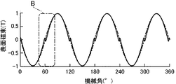
図3(b)は、図2に示すような、セグメント磁石の周方向端部における端面の角部が4分円形状の断面を有するモデル化された間隙の形状について計算により求めた、図3(a)に符号Bで示す極間領域における磁束分布を表す図表であり、横軸の目盛を拡張して示してある。図3(b)から分かるように、複数の円弧状セグメント磁石を周方向にリング状に配列して形成される極異方リング磁石では、極間領域に間隙gが不可避的に形成されるため、該間隙gに対応する領域において、磁束分布が正弦波形状から大きく外れるようになる。 FIG. 3B is a graph showing the shape of the modeled gap having the quadrant-shaped cross section of the end face at the circumferential end of the segment magnet as shown in FIG. It is a chart showing the magnetic flux distribution in the inter-electrode area indicated by reference sign B in (a), and the scale of the horizontal axis is expanded and shown. As can be seen from FIG. 3B, in the polar anisotropic ring magnet formed by arranging a plurality of arc-shaped segment magnets in a ring shape in the circumferential direction, the gap g is unavoidably formed in the inter-pole region. In the area corresponding to the gap g, the magnetic flux distribution largely deviates from the sinusoidal shape.
本発明においては、該極間領域における磁化方向を補正することにより、磁束分布のずれを大幅に軽減するか、或いは解消する。以下、本発明の実施形態を、図を参照して詳細に説明する。
〔第一の実施形態〕
In the present invention, the deviation of the magnetic flux distribution is significantly reduced or eliminated by correcting the magnetization direction in the inter-electrode region. Hereinafter, embodiments of the present invention will be described in detail with reference to the drawings.
[First embodiment]
図4に、6極の極異方リング磁石を形成するための、本発明の第一の実施形態によるセグメント磁石11が示されている。このセグメント磁石11は、その基本的形状が、図1(a)に示すセグメント磁石1と同一で、点Oに曲率中心を有する円弧形状であり、6極の極異方リング磁石における1極分に相当する角度範囲2λの周長にわたって配置されるものである。セグメント磁石11は、周方向に隣接するセグメント磁石12との間に前述した角度2dに相当する間隙gが形成されるため、図1(a)を参照して前述したように、セグメント磁石11の周長は、1極分に相当する角度範囲2λより角度範囲2dだけ小さい角度範囲2ωとなる。
FIG. 4 shows a
本実施形態では、セグメント磁石11は、各端の端面11aから周方向内方に向かって角度範囲εωにわたる範囲が端部領域13とされており、残りの部分が中央領域14とされる。中央領域14においては、図1(a)に示すセグメント磁石1におけると同様に、磁化方向は、式(1)で表される「極異方配向」である。しかしながら、本実施形態では、極間領域における磁化方向を補正するために、端部領域13における磁化方向を、
Φ(θ)=(π/2λ)・θ−m[(θ/λ)−1+α)]n ・・・(2)
又は、
Φ(θ)=(90°/λ)・θ−m[(θ/λ)−1+α)]n ・・・(2)
とする。式(2)において、右辺の第2項は修正項である。ここで、「α」は、端部領域13を定める半径線13aと間隙gの2等分半径線Rgとの間の角度範囲を「αλ」として表示した係数「α」である。図4において、[(90°−d)/90°]λ=ω、1−α=[(90°−d)/90°](1−ε)であるから、式(2)は、下記のように表すことができる。
Φ(θ)=[(90°−d)/ω]θ
−m[(90°−d)/90°]n・[(θ/ω)−1+ε]n・・・(3)
In the present embodiment, the
Φ(θ)=(π/2λ)·θ-m[(θ/λ)-1+α)] n (2)
Or
Φ(θ)=(90°/λ)·θ-m[(θ/λ)-1+α)] n (2)
And In Expression (2), the second term on the right side is a correction term. Here, “α” is a coefficient “α” in which the angular range between the
Φ(θ)=[(90°−d)/ω]θ
-M [(90°-d)/90°] n ·[(θ/ω)-1+ε] n (3)
ここで、dは90°に比べて極めて小さい値であるので、上記の式(3)の右辺第2項における[(90°−d)/90°]nを「1」にほぼ等しいとして取り扱うと、式(2)は下記のように表されることになる。
Φ(θ)=[(90°−d)/ω]θ−m[(θ/ω)−1+ε]n・・・(4)
Here, since d is an extremely small value compared to 90°, [[90°-d)/90°] n in the second term on the right side of the above equation (3) is treated as being substantially equal to “1”. Then, the equation (2) is expressed as follows.
Φ(θ)=[(90°−d)/ω]θ−m[(θ/ω)−1+ε] n (4)
本実施形態では、式(4)において、mを(π/2)−dすなわち90°−dとし、nを1とする。その結果、端部領域13における磁化方向Φ(θ)は、下記の式で表されるものとなる。
Φ(θ)=(1−ε)(90°−d) ・・・・・・・ (5)
In the present embodiment, m is (π/2)-d, that is, 90°-d, and n is 1 in Expression (4). As a result, the magnetization direction Φ(θ) in the
Φ(θ)=(1-ε) (90°-d) ···· (5)
端部領域13における磁化方向が式(5)に基づいて定められる本実施形態によるセグメント磁石11における角度θ、Φの関係を、横軸にθ/λを、縦軸にΦをとって示すと図5のようになる。図5から分かるように、本実施形態のセグメント磁石11においては、端部領域13における磁化方向角度は、角度θに関係なく一定である。
The relationship between the angles θ and Φ in the
このセグメント磁石11は、希土類物質を含む磁石材料粒子を焼結することによって製造される。製造の過程で、セグメント磁石の形状に成形された磁石材料粒子の成形体に外部磁界を印加して、該磁石材料粒子の磁化容易軸を、セグメント磁石における磁化方向に対応する方向に指向させ、焼結を行うことにより、本発明の実施形態である、磁石材料粒子の磁化容易軸が所定の方向に指向された、希土類磁石形成用焼結体が得られる。さらに、この希土類磁石形成用焼結体に外部磁界を印加することにより、上述した磁化方向を有する希土類永久磁石が得られる。このようにして形成された円弧形状の希土類永久磁石は、回転電機の回転子の周面にリング状に配置されてリング磁石を構成する。
[第二の実施形態]
The
[Second embodiment]
本実施形態は、上記式(4)において、mを(π/2)−d+(Δ/ε)、nを1とすること以外は、実施形態1と全く同じである。ここに、Δは任意に定められる定数である。この場合、端部領域13における磁化方向Φ(θ)は、下記の式で表されるものとなる。
Φ(θ)=(1−ε)(90°−d)−[θ−(1−ε)ω](Δ/εω)・・・(6)
The present embodiment is exactly the same as the first embodiment except that m is (π/2)-d+(Δ/ε) and n is 1 in the above formula (4). Here, Δ is a constant that is arbitrarily determined. In this case, the magnetization direction Φ(θ) in the
Φ(θ)=(1−ε)(90°−d)−[θ−(1−ε)ω](Δ/εω) (6)
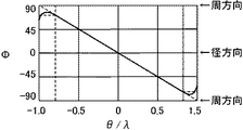
端部領域13における磁化方向が式(6)に基づいて定められる本実施形態によるセグメント磁石11における角度θ、Φの関係は、横軸にθ/λを、縦軸にΦをとって示すと図6のようになる。図6から分かるように、本実施形態のセグメント磁石11においては、端部領域13における磁化方向角度は、角度θの絶対値の増加に反比例して直線的に減少する。
The relationship between the angles θ and Φ in the
なお、Δは0<Δ≦(1−ε)・(90°−d)の範囲内の定数であり、例えば、10°ないし70°の範囲に設定することができる。
[第三の実施形態]
In addition, Δ is a constant within the range of 0<Δ≦(1−ε)·(90°−d), and can be set in the range of 10° to 70°, for example.
[Third embodiment]
本実施形態は、上記式(4)において、m>1、n>1の任意に定められる定数とすること以外は、実施形態1及び実施形態2と全く同じである。この場合、端部領域13における磁化方向Φ(θ)は、下記の式で表されるものとなる。
Φ(θ)=(90°−d)θ/ω−m[(θ/ω)−(1−ε)]n ・・・(7)
The present embodiment is exactly the same as the first and second embodiments, except that m>1 and n>1 are arbitrarily set constants in the above formula (4). In this case, the magnetization direction Φ(θ) in the
Φ(θ)=(90°-d)θ/ω-m [(θ/ω)-(1-ε)] n (7)
端部領域13における磁化方向が式(7)に基づいて定められる本実施形態によるセグメント磁石11における角度θ、Φの関係は、横軸にθ/λを、縦軸にΦをとって示すと図7のようになる。図7から分かるように、本実施形態のセグメント磁石11においては、端部領域13における磁化方向角度は、角度θに応じてべき乗則に基づき変化するものとなる。
The relationship between the angles θ and Φ in the
また、Φが式(7)に基づいてべき乗則で変化する領域においても、極異方配向からのずれがほとんど無い領域がある。この領域では実質、極異方配向とみなす事ができ、中央領域14に含むことができる。極異方配向からずれた配向となる端部領域13を定義するεと区別するために、式(7)は下記の式のように表す。
Φ(θ)=(90°−d)θ/ω−m[(θ/ω)−(1−η)]n ・・・(8)
なお、ηは0.2≦η≦0.9の範囲の定数であり、nは1より大きい数であれば特には限定されず、例えば、2ないし10の範囲に設定することができる。また、mは1より大きい数であれば特には限定されず、例えば、100ないし5000の範囲に設定することができる。
Further, even in a region where Φ changes according to the power law based on the equation (7), there is a region where there is almost no deviation from the polar anisotropic orientation. In this region, it can be regarded as a substantially anisotropic orientation and can be included in the
Φ(θ)=(90°−d)θ/ω−m[(θ/ω)−(1−η)] n (8)
Note that η is a constant in the range of 0.2≦η≦0.9, and n is not particularly limited as long as it is a number greater than 1, and can be set in the range of 2 to 10, for example. Further, m is not particularly limited as long as it is a number larger than 1, and can be set in the range of 100 to 5000, for example.
実施形態1、2及び3に基づくセグメント磁石11を、回転子の週面にリング状に配置した回転電機について、セグメント磁石間の間隙gを変えた場合の実施例1ないし3、及び極数を変えた場合の実施例4ないし7について、セグメント磁石間間隙部近傍における表面磁束歪み率を計算により求めた。その結果を表1に示す。表1から分かるように、実施形態1より実施形態2、実施形態2より実施形態3の方が、高い歪み率減少効果を示しているが、いずれの実施形態も、従来技術に比べると、優れた歪み率減少効果を達成することができる。表1の結果から、本発明において、セグメント磁石間の間隙gの角度値2dにおけるdは、5以下であることが必要で、より好ましくは3以下である。

以下、本発明による希土類磁石形成用焼結体を製造する方法の実施例を説明する。
先ず、図4及び図5に示す第一の実施形態による希土類磁石形成用焼結体1の製造方法について図8を参照して説明する。図8は、第一の実施形態に係る永久磁石形成用焼結体1の製造工程を示す概略図である。
Hereinafter, examples of the method for producing a sintered body for forming a rare earth magnet according to the present invention will be described.
First, a method of manufacturing the
先ず、所定分率のNd−Fe−B系合金からなる磁石材料のインゴットを鋳造法により製造する。代表的には、ネオジム磁石に使用されるNd−Fe−B系合金は、Ndが30wt%、電解鉄であることが好ましいFeが67wt%、Bが1.0wt%の割合で含まれる組成を有する。次いで、このインゴットを、スタンプミル又はクラッシャー等の公知の手段を使用して200μm程度の大きさに粗粉砕する。代替的には、インゴットを溶解し、ストリップキャスト法によりフレークを作製し、水素解砕法で粗粉化する。それによって、粗粉砕磁石材料粒子115が得られる(図8(a)参照)。
First, an ingot of a magnetic material made of a predetermined fraction of Nd-Fe-B alloy is manufactured by a casting method. Typically, the Nd-Fe-B-based alloy used for the neodymium magnet has a composition containing Nd of 30 wt%, Fe which is preferably electrolytic iron of 67 wt%, and B of 1.0 wt%. Have. Next, this ingot is roughly crushed to a size of about 200 μm using a known means such as a stamp mill or a crusher. Alternatively, the ingot is melted, flakes are made by the strip casting method, and coarsely pulverized by the hydrogen crushing method. Thereby, the coarsely pulverized
次いで、粗粉砕磁石材料粒子115を、ビーズミル116による湿式法又はジェットミルを用いた乾式法等によって微粉砕する。例えば、ビーズミル116による湿式法を用いた微粉砕では、溶媒中で粗粉砕磁石粒子115を所定範囲の粒径(例えば0.1μmないし5.0μm)に微粉砕し、溶媒中に磁石材料粒子を分散させる(図8(b)参照)。その後、湿式粉砕後の溶媒に含まれる磁石粒子を真空乾燥などの手段によって乾燥させて、乾燥した磁石粒子を取り出す(図示せず)。ここで、粉砕に用いる溶媒の種類には特に制限はなく、イソプロピルアルコール、エタノール、メタノールなどのアルコール類、酢酸エチル等のエステル類、ペンタン、ヘキサンなどの低級炭化水素類、ベンゼン、トルエン、キシレンなど芳香族類、ケトン類、それらの混合物等の有機溶媒、又は、液化アルゴン等の無機溶媒を使用することができる。この場合において、溶媒中に酸素原子を含まない溶媒を用いることが好ましい。
Next, the coarsely pulverized
一方、ジェットミルによる乾式法を用いる微粉砕においては、粗粉砕した磁石材料粒子115を、(a)酸素含有量が実質的に0%の窒素ガス、Arガス、Heガスなどの不活性ガスからなる雰囲気中、又は(b)酸素含有量が0.0001ないし0.5%の窒素ガス、Arガス、Heガスなどの不活性ガスからなる雰囲気中で、ジェットミルにより微粉砕し、例えば0.7μmないし5.0μmといった所定範囲の平均粒径を有する微粒子とする。ここで、酸素濃度が実質的に0%とは、酸素濃度が完全に0%である場合に限定されず、微粉の表面にごく僅かに酸化被膜を形成する程度の量の酸素を含有しても良いことを意味する。
On the other hand, in fine pulverization using a dry method using a jet mill, the coarsely pulverized
次に、ビーズミル116等で微粉砕された磁石材料粒子を所望形状に成形する。この磁石材料粒子の成形のために、上述のように微粉砕された磁石材料粒子115とバインダーとを混合した混合物、すなわちコンパウンド117を準備する。バインダーとしては、樹脂材料を用いることが好ましく、バインダーに樹脂を用いる場合には、構造中に酸素原子を含まず、かつ解重合性のあるポリマーを用いるのが好ましい。また、後述のように磁石粒子とバインダーとの混合物117を、例えば台形形状のような所望形状に成形する際に生じた混合物の残余物を再利用できるようにするために、かつ、混合物を加熱して軟化した状態で磁場配向を行うことができるようにするために、熱可塑性樹脂を用いることが好ましい。具体的には、以下の一般式(1)に示されるモノマーから形成される1種又は2種以上の重合体又は共重合体からなるポリマーが好適に用いられる。
上記条件に該当するポリマーとしては、例えばイソブチレンの重合体であるポリイソブチレン(PIB)、イソプレンの重合体であるポリイソプレン(イソプレンゴム、IR)、1,3−ブタジエンの重合体であるポリブタジエン(ブタジエンゴム、BR)、スチレンの重合体であるポリスチレン、スチレンとイソプレンの共重合体であるスチレン−イソプレンブロック共重合体(SIS)、イソブチレンとイソプレンの共重合体であるブチルゴム(IIR)、スチレンとブタジエンの共重合体であるスチレン−ブタジエンブロック共重合体(SBS)、スチレンとエチレン、ブタジエンの共重合体であるスチレン-エチレン-ブタジエン-スチレン共重合体(SEBS)、スチレンとエチレン、プロピレンの共重合体であるスチレン-エチレン-プロピレン-スチレン共重合体(SEPS)、エチレンとプロピレンの共重合体であるエチレン-プロピレン共重合体(EPM)、エチレン、プロピレンとともにジエンモノマーを共重合させたEPDM、エチレンの重合体であるポリエチレン、プロピレンの重合体であるポリプロピレン、2−メチル−1−ペンテンの重合体である2−メチル−1−ペンテン重合樹脂、2−メチル−1−ブテンの重合体である2−メチル−1−ブテン重合樹脂、α−メチルスチレンの重合体であるα−メチルスチレン重合樹脂等がある。また、バインダーに用いる樹脂としては、酸素原子、窒素原子を含むモノマーの重合体又は共重合体(例えば、ポリブチルメタクリレートやポリメチルメタクリレート等)を少量含む構成としても良い。更に、上記一般式(1)に該当しないモノマーが一部共重合していても良い。その場合であっても、本発明の目的を達成することが可能である。 Examples of the polymer satisfying the above conditions include polyisobutylene (PIB) which is a polymer of isobutylene, polyisoprene (isoprene rubber, IR) which is a polymer of isoprene, and polybutadiene (butadiene which is a polymer of 1,3-butadiene). Rubber, BR), polystyrene which is a polymer of styrene, styrene-isoprene block copolymer (SIS) which is a copolymer of styrene and isoprene, butyl rubber (IIR) which is a copolymer of isobutylene and isoprene, styrene and butadiene Styrene-butadiene block copolymer (SBS) which is a copolymer of styrene, styrene-ethylene-butadiene-styrene copolymer (SEBS) which is a copolymer of styrene, ethylene and butadiene, and copolymerization of styrene with ethylene and propylene Styrene-ethylene-propylene-styrene copolymer (SEPS) which is a polymer, ethylene-propylene copolymer (EPM) which is a copolymer of ethylene and propylene, EPDM in which a diene monomer is copolymerized with ethylene and propylene, and ethylene Which is a polymer of polyethylene, polypropylene which is a polymer of propylene, 2-methyl-1-pentene polymer resin which is a polymer of 2-methyl-1-pentene, and a polymer of 2-methyl-1-butene 2 -Methyl-1-butene polymer resin, α-methylstyrene polymer resin which is a polymer of α-methylstyrene, and the like. In addition, the resin used for the binder may be configured to contain a small amount of a polymer or copolymer (for example, polybutyl methacrylate or polymethyl methacrylate) of a monomer containing an oxygen atom or a nitrogen atom. Furthermore, some monomers not corresponding to the above general formula (1) may be copolymerized. Even in that case, the object of the present invention can be achieved.
なお、バインダーに用いる樹脂としては、磁場配向を適切に行う為に250℃以下で軟化する熱可塑性樹脂、より具体的にはガラス転移点又は流動開始温度が250℃以下の熱可塑性樹脂を用いることが望ましい。 As the resin used for the binder, a thermoplastic resin that softens at 250° C. or lower in order to appropriately perform magnetic field orientation, more specifically, a thermoplastic resin having a glass transition point or a flow starting temperature of 250° C. or lower is used. Is desirable.
熱可塑性樹脂中に磁石材料粒子を分散させるために、分散剤を適量添加する事が望ましい。分散剤としては、アルコール、カルボン酸、ケトン、エーテル、エステル、アミン、イミン、イミド、アミド、シアン、リン系官能基、スルホン酸、二重結合や三重結合などの不飽和結合を有する化合物、液状飽和炭化水素化合物のうち、少なくともひとつを添加することが望ましい。複数を混合して用いても良い。 そして、後述するように、磁石材料粒子とバインダーとの混合物に対して磁場を印加して該磁石材料を磁場配向するにあたっては、混合物を加熱してバインダー成分が軟化した状態で磁場配向処理を行う。 In order to disperse the magnetic material particles in the thermoplastic resin, it is desirable to add an appropriate amount of a dispersant. As the dispersant, alcohol, carboxylic acid, ketone, ether, ester, amine, imine, imide, amide, cyan, phosphorus functional group, sulfonic acid, compound having unsaturated bond such as double bond or triple bond, liquid It is desirable to add at least one of the saturated hydrocarbon compounds. You may mix and use two or more. Then, as will be described later, when a magnetic field is applied to the mixture of the magnet material particles and the binder to orient the magnetic material, the mixture is heated to perform the magnetic field orientation treatment in a state where the binder component is softened. ..
磁石材料粒子に混合されるバインダーとして上記条件を満たすバインダーを用いることによって、焼結後の希土類永久磁石形成用焼結体内に残存する炭素量及び酸素量を低減させることが可能となる。具体的には、焼結後に磁石形成用焼結体内に残存する炭素量を2000ppm以下、より好ましくは1000ppm以下とすることができる。また、焼結後に磁石形成用焼結体内に残存する酸素量を5000ppm以下、より好ましくは2000ppm以下とすることができる。 By using a binder satisfying the above conditions as the binder mixed with the magnet material particles, it becomes possible to reduce the amount of carbon and the amount of oxygen remaining in the sintered body for forming the rare earth permanent magnet after sintering. Specifically, the amount of carbon remaining in the magnet-forming sintered body after sintering can be 2000 ppm or less, and more preferably 1000 ppm or less. Further, the amount of oxygen remaining in the sintered body for magnet formation after sintering can be set to 5000 ppm or less, more preferably 2000 ppm or less.
バインダーの添加量は、スラリー又は加熱溶融した混合物すなわちコンパウンド117を成形する場合に、成形の結果として得られる成形体の厚み精度が向上するように、磁石材料粒子間の空隙を適切に充填できる量とする。例えば、磁石材料粒子とバインダーの合計量に対するバインダーの比率が、1wt%ないし40wt%、より好ましくは2wt%ないし30wt%、更に好ましくは3wt%ないし20wt%とする。
The amount of the binder added is an amount that can appropriately fill the voids between the magnetic material particles so that when molding the slurry or the heat-melted mixture, that is, the
以下の実施例では、混合物を一旦製品形状以外に成形した状態で磁場を印加して磁場磁石材料粒子の配向を行い、その後に焼結処理を行うことによって、例えば図1に示す円弧形状のような、所望の製品形状とする。特に、以下の実施例では、磁石材料粒子とバインダーとからなる混合物すなわちコンパウンド117を、シート形状のグリーン成形体(以下、「グリーンシート」という)に一旦成形した後に、配向処理のための成形体形状とする。混合物を特にシート形状に成形する場合には、例えば磁石材料粒子とバインダーとの混合物であるコンパウンド117を加熱した後にシート形状に成形するホットメルト塗工によるか、又は、磁石材料粒子とバインダーと有機溶媒とを含むスラリーを基材上に塗工することによりシート状に成形するスラリー塗工等による成形を採用することができる。
In the following examples, a magnetic field is applied in a state where the mixture is once formed into a shape other than the product shape, the magnetic field magnet material particles are oriented, and then the sintering treatment is performed, so that, for example, an arc shape shown in FIG. The desired product shape. In particular, in the following examples, a mixture of the magnetic material particles and the binder, that is, the
以下においては、特にホットメルト塗工を用いたグリーンシート成形について説明するが、本発明は、そのような特定の成形法に限定されるものではない。例えば、コンパウンド117を成形用型に入れ、室温〜300℃に加熱しながら、0.1〜100MPa加圧することで成形を行ってもよい。この場合、より具体的には、軟化する温度に加熱したコンパウンド117を、射出圧を加えて金型に押込み充填して成形する方法が挙げられる。
In the following, green sheet molding using hot melt coating will be described in particular, but the present invention is not limited to such a specific molding method. For example, the
既に述べたように、ビーズミル116等で微粉砕された磁石材料粒子にバインダーを混合することにより、磁石材料粒子とバインダーとからなる粘土状の混合物すなわちコンパウンド117を作製する。ここで、バインダーとしては、上述したように樹脂、分散剤の混合物を用いることができる。例えば、樹脂としては、構造中に酸素原子を含まず、かつ解重合性のあるポリマーからなる熱可塑性樹脂を用いることが好ましく、一方、分散剤としては、アルコール、カルボン酸、ケトン、エーテル、エステル、アミン、イミン、イミド、アミド、シアン、リン系官能基、スルホン酸、二重結合や三重結合などの不飽和結合を有する化合物のうち、少なくともひとつを添加することが好ましい。また、バインダーの添加量は、上述したように添加後のコンパウンド117における磁石材料粒子とバインダーの合計量に対するバインダーの比率が、1wt%ないし40wt%、より好ましくは2wt%ないし30wt%、さらに好ましくは3wt%ないし20wt%となるようにする。
As described above, the binder is mixed with the magnetic material particles finely pulverized by the
ここで分散剤の添加量は磁石材料粒子の粒子径に応じて決定することが好ましく、磁石材料粒子の粒子径が小さい程、添加量を多くすることが推奨される。具体的な添加量としては、磁石材料粒子に対して0.1部ないし10部、より好ましくは0.3部ないし8部とする。添加量が少ない場合には分散効果が小さく、配向性が低下する恐れがある。また、添加量が多い場合は、磁石材料粒子を汚染する恐れがある。磁石材料粒子に添加された分散剤は、磁石材料粒子の表面に付着し、磁石材料粒子を分散させ粘土状混合物を与えるとともに、後述の磁場配向処理において、磁石材料粒子の回動を補助するように作用する。その結果、磁場を印加した際に配向が容易に行われ、磁石粒子の磁化容易軸方向をほぼ同一方向に揃えること、すなわち、配向度を高くすることが可能になる。特に、磁石材料粒子にバインダーを混合する場合には、粒子表面にバインダーが存在するようになるため、磁場配向処理時の摩擦力が高くなり、そのために粒子の配向性が低下する恐れがあり、分散剤を添加することの効果がより高まる。 Here, the amount of the dispersant added is preferably determined according to the particle diameter of the magnetic material particles, and it is recommended to increase the addition amount as the particle diameter of the magnetic material particles is smaller. The specific addition amount is 0.1 part to 10 parts, more preferably 0.3 part to 8 parts, relative to the magnet material particles. When the addition amount is small, the dispersion effect is small and the orientation may be deteriorated. Further, when the addition amount is large, the magnet material particles may be contaminated. The dispersant added to the magnetic material particles adheres to the surface of the magnetic material particles, disperses the magnetic material particles to give a clay-like mixture, and assists the rotation of the magnetic material particles in the magnetic field orientation treatment described later. Act on. As a result, the orientation is easily performed when a magnetic field is applied, and the easy axis of magnetization of the magnet particles can be aligned in substantially the same direction, that is, the degree of orientation can be increased. In particular, when the binder is mixed with the magnetic material particles, the binder will be present on the surface of the particles, so that the frictional force at the time of the magnetic field orientation treatment becomes high, which may reduce the orientation of the particles. The effect of adding the dispersant is further enhanced.
磁石材料粒子とバインダーとの混合は、窒素ガス、Arガス、Heガスなどの不活性ガスからなる雰囲気のもとで行うことが好ましい。磁石材料粒子とバインダーとの混合は、例えば磁石材料粒子とバインダーをそれぞれ攪拌機に投入し、攪拌機で攪拌することにより行う。この場合において、混練性を促進する為に加熱攪拌を行っても良い。さらに、磁石材料粒子とバインダーの混合も、窒素ガス、Arガス、Heガスなど不活性ガスからなる雰囲気で行うことが望ましい。また、特に磁石粒子を湿式法で粉砕した場合においては、粉砕に用いた溶媒から磁石粒子を取り出すことなくバインダーを溶媒中に添加して混練し、その後に溶媒を揮発させ、コンパウンド117を得るようにしても良い。
It is preferable to mix the magnetic material particles and the binder in an atmosphere of an inert gas such as nitrogen gas, Ar gas, or He gas. The mixing of the magnetic material particles and the binder is performed by, for example, charging the magnetic material particles and the binder into a stirrer and stirring them with the stirrer. In this case, heating and stirring may be performed in order to promote the kneading property. Further, it is desirable to mix the magnet material particles and the binder in an atmosphere of an inert gas such as nitrogen gas, Ar gas or He gas. Further, particularly when the magnet particles are pulverized by a wet method, a binder is added to the solvent and kneaded without taking out the magnet particles from the solvent used for the pulverization, and then the solvent is volatilized to obtain the
続いて、コンパウンド117をシート状に成形することにより、前述したグリーンシートを作成する。ホットメルト塗工を採用する場合には、コンパウンド117を加熱することにより該コンパウンド117を溶融し、流動性を有する状態にした後、支持基材118上に塗工する。その後、放熱によりコンパウンド117を凝固させて、支持基材118上に長尺シート状のグリーンシート119を形成する。この場合、コンパウンド117を加熱溶融する際の温度は、用いるバインダーの種類や量によって異なるが、通常は50ないし300℃とする。但し、用いるバインダーの流動開始温度よりも高い温度とする必要がある。なお、スラリー塗工を用いる場合には、多量の溶媒中に磁石材料粒子とバインダー、及び、任意ではあるが、配向を助長する添加剤を分散させ、スラリーを支持基材118上に塗工する。その後、乾燥して溶媒を揮発させることにより、支持基材118上に長尺シート状のグリーンシート119を形成する。
Subsequently, the
ここで、溶融したコンパウンド117の塗工方式は、スロットダイ方式又はカレンダーロール方式等の、層厚制御性に優れる方式を用いることが好ましい。特に、高い厚み精度を実現する為には、特に層厚制御性に優れた、すなわち、基材の表面に高精度の厚さの層を塗工できる方式であるダイ方式やコンマ塗工方式を用いることが望ましい。例えば、スロットダイ方式では、加熱して流動性を有する状態にしたコンパウンド117をギアポンプにより圧送してダイに注入し、ダイから吐出することにより塗工を行う。また、カレンダーロール方式では、加熱した2本のロールのニップ間隙に、コンパウンド117を制御した量で送り込み、ロールを回転させながら、支持基材118上に、ロールの熱で溶融したコンパウンド117を塗工する。支持基材118としては、例えばシリコーン処理ポリエステルフィルムを用いることが好ましい。さらに、消泡剤を用いるか、加熱真空脱泡を行うことによって、塗工され展開されたコンパウンド117の層中に気泡が残らないよう、充分に脱泡処理することが好ましい。或いは、支持基材118上に塗工するのではなく、押出成型や射出成形によって溶融したコンパウンド117をシート状に成型しながら支持基材118上に押し出すことによって、支持基材118上にグリーンシート119を成形することもできる。
Here, as the coating method of the melted
図8に示す実施形態では、スロットダイ120を用いてコンパウンド117の塗工を行うようにしている。このスロットダイ方式によるグリーンシート119の形成工程では、塗工後のグリーンシート119のシート厚みを実測し、その実測値に基づいたフィードバック制御により、スロットダイ120と支持基材118との間のニップ間隙を調節することが望ましい。この場合において、スロットダイ120に供給する流動性コンパウンド117の量の変動を極力低下させ、例えば±0.1%以下の変動に抑え、さらに塗工速度の変動も極力低下させ、例えば±0.1%以下の変動に抑えることが望ましい。このような制御によって、グリーンシート119の厚み精度を向上させることが可能である。なお、形成されるグリーンシート119の厚み精度は、例えば1mmといった設計値に対して、±10%以内、より好ましくは±3%以内、さらに好ましくは±1%以内とすることが好ましい。カレンダーロール方式では、カレンダー条件を同様に実測値に基づいてフィードバック制御することで、支持基材118に転写されるコンパウンド117の膜厚を制御することが可能である。
In the embodiment shown in FIG. 8, the
グリーンシート119の厚みは、0.05mmないし20mmの範囲に設定することが望ましい。厚みを0.05mmより薄くすると、必要な磁石厚みを達成するために、多層積層しなければならなくなるので、生産性が低下することになる。
〔第一の実施形態による焼結体の製造〕
The thickness of the
[Production of sintered body according to first embodiment]
次に、上述したホットメルト塗工によって支持基材118上に形成されたグリーンシート119から所望の磁石寸法に対応する寸法に切り出された加工用シート片123を作成する。本実施形態においては、加工用シート片123は、図9(a)に示すように、最終製品となる希土類永久磁石形成用焼結体1における中央領域に対応する円弧状領域123aと、該円弧状領域123aの両端に連続する直線状領域123b、123cを有する断面形状である。円弧状領域123aは、図9(a)にOで示す点に曲率中心を有する円弧形状であり、該円弧状領域123aの両端部に連続する直線状領域123b、123cのうち、曲率中心O周りに角度εω、すなわち、ε×90°の範囲が図4に示すセグメント磁石の端部領域13に対応する端部領域となる。この加工用シート片123は、図の紙面に直角な方向の長さ寸法を有し、断面の寸法及び長さ寸法は、後述する焼結工程における寸法の縮小を見込んで、焼結工程後に所定の磁石寸法が得られるように定める。
Next, the
図9(a)に示す加工用シート片123には、曲率中心Oと円弧状領域123aの円周方向中心点Aとを結ぶ方向に平行な平行磁場121が印加される。この磁場印加により、加工用シート片123に含まれる磁石材料粒子の磁化容易軸が、図9(a)に矢印122で示すように、磁場の方向に、すなわち厚み方向に平行に配向される。具体的に述べると、加工用シート片123は、該加工用シート片123に対応する形状のキャビティを有する磁場印加用型内に収容され(図示せず)、加熱することにより加工用シート片123に含まれるバインダーを軟化させる。それによって、磁石材料粒子はバインダー内で回動できるようになり、その磁化容易軸を平行磁場121に沿った方向に配向させることができる。
A parallel
ここで、加工用シート片123を加熱するための温度及び時間は、用いるバインダーの種類及び量によって異なるが、例えば40ないし250℃で0.1ないし60分とする。いずれにしても、加工用シート片123内のバインダーを軟化させるためには、加熱温度は、用いられるバインダーのガラス転移点又は流動開始温度以上の温度とする必要がある。加工用シート片123を加熱するための手段としては、例えばホットプレートによる加熱、又はシリコーンオイルのような熱媒体を熱源に用いる方式がある。磁場印加における磁場の強さは、5000[Oe]ないし150000[Oe]、好ましくは、10000[Oe]ないし120000[Oe]とすることができる。その結果、加工用シート片123に含まれる磁石材料結晶の磁化容易軸が、図9(a)に示すように、平行磁場121に沿った方向に、平行に配向される。この磁場印加工程では、複数個の加工用シート片123に対して同時に磁場を印加する構成とすることもできる。このためには、複数個のキャビティを有する型を使用するか、或いは、複数個の型を並べて、同時に平行磁場121を印加すればよい。加工用シート片123に磁場を印加する工程は、加熱工程と同時に行っても良いし、加熱工程を行った後であって加工用シート片123のバインダーが凝固する前に行っても良い。
Here, the temperature and time for heating the
次に、図9(a)に示す磁場印加工程により磁石材料粒子の磁化容易軸が矢印122で示すように平行配向された加工用シート片123を、磁場印加用型から取り出し、図9(b)に示す円弧状キャビティ124を有する最終成形用型内に移して、焼結処理用シート片125に成形する。この成形により、加工用シート片123は、中央の円弧状領域123aと両端の直線状領域123b、123cが、互いに連続する同一曲率半径の円弧形状になり、焼結用シート片125が形成される。この成形工程により形成される焼結処理用シート片125においては、中央の中心線O−Aに沿って位置する磁石材料粒子の磁化容易軸は、円弧の半径方向に配向された状態になり、中心線O−Aの両側の領域においては、変形の結果、図9(b)に示すように、磁化容易軸は、極異方配向になる。
Next, the
このようにして磁石材料粒子の磁化容易軸が配向された配向後の焼結処理用シート片125は、図9(c)に示すように、両端部が、上述した角度εωに相当する部分を残して切り落とされて、焼結用シート片125aとなる。この焼結用シート片125aに対して、大気圧、或いは、大気圧より高い圧力又は低い圧力(例えば、1.0Pa又は1.0MPa)に調節した非酸化性雰囲気において、バインダー分解温度で数時間ないし数十時間(例えば5時間)保持することにより仮焼処理を行う。この処理では、水素雰囲気又は水素と不活性ガスの混合ガス雰囲気を用いることが推奨される。水素雰囲気のもとで仮焼処理を行う場合には、仮焼中の水素の供給量は、例えば5L/minとする。仮焼処理を行うことによって、バインダーに含まれる有機化合物を、解重合反応、その他の反応によりモノマーに分解し、飛散させて除去することが可能となる。すなわち、焼結処理用シート片125aに残存する炭素の量を低減させる処理である脱カーボン処理が行われることとなる。また、仮焼処理は、焼結処理用シート片125a内に残存する炭素の量が2000ppm以下、より好ましくは1000ppm以下とする条件で行うことが望ましい。それによって、その後の焼結処理で焼結処理用シート片125aの全体を緻密に焼結させることが可能となり、残留磁束密度及び保磁力の低下を抑制することが可能になる。なお、上述した仮焼処理を行う際の加圧条件を大気圧より高い圧力とする場合には、圧力は15MPa以下とすることが望ましい。ここで、加圧条件は、大気圧より高い圧力、より具体的には0.2MPa以上とすれば、特に残存炭素量軽減の効果が期待できる。
As shown in FIG. 9C, the sintered
バインダー分解温度は、バインダー分解生成物および分解残渣の分析結果に基づき決定することができる。具体的には、バインダーの分解生成物を補集し、モノマー以外の分解生成物が生成せず、かつ残渣の分析においても残留するバインダー成分の副反応による生成物が検出されない温度範囲を選択することが推奨される。バインダーの種類により異なるが、200℃ないし900℃、より好ましくは400℃ないし500℃、例えば450℃とすればよい。 The binder decomposition temperature can be determined based on the analysis result of the binder decomposition product and the decomposition residue. Specifically, a temperature range is selected in which the decomposition products of the binder are collected, the decomposition products other than the monomers are not generated, and the residual reaction product of the binder component is not detected even in the analysis of the residue. Is recommended. Although it depends on the kind of binder, it may be 200° C. to 900° C., more preferably 400° C. to 500° C., for example 450° C.
上述の仮焼処理においては、一般的な希土類磁石の焼結処理と比較して、昇温速度を小さくすることが好ましい。具体的には、昇温速度を2℃/min以下、例えば1.5℃/minとすることにより、好ましい結果を得ることができる。従って、仮焼処理を行う場合には、図11に示すように2℃/min以下の所定の昇温速度で昇温し、予め設定された設定温度(バインダー分解温度)に到達した後に、該設定温度で数時間ないし数十時間保持することにより仮焼処理を行う。このように、仮焼処理において昇温速度を小さくすることによって、焼結処理用シート片125a内の炭素が急激に除去されることがなく、段階的に除去されるようになるので、十分なレベルまで残量炭素を減少させて、焼結後の永久磁石形成用焼結体の密度を高めることが可能となる。すなわち、残留炭素量を減少させることにより、永久磁石中の空隙を減少させることができる。上述のように、昇温速度を2℃/min以下とすれば、焼結後の永久磁石形成用焼結体の密度を98%以上(7.40g/cm3以上)とすることができ、着磁後の磁石において高い磁石特性を達成することが期待できる。
In the above-mentioned calcination treatment, it is preferable to reduce the temperature rising rate as compared with the general sintering treatment of rare earth magnets. Specifically, a preferable result can be obtained by setting the temperature rising rate to 2° C./min or less, for example, 1.5° C./min. Therefore, when performing the calcination process, as shown in FIG. 11, the temperature is raised at a predetermined temperature rising rate of 2° C./min or less, and after reaching a preset set temperature (binder decomposition temperature), The calcination process is performed by maintaining the temperature for several hours to several tens of hours. As described above, by decreasing the temperature rising rate in the calcination process, carbon in the sintering
続いて、仮焼処理によって仮焼された焼結処理用シート片125を焼結する焼結処理が行われる。焼結処理としては、真空中での無加圧焼結法を採用することもできるが、本実施形態では、焼結処理用シート片125aを長さ方向に一軸加圧した状態で焼結する一軸加圧焼結法を採用することが好ましい。この方法では、図9(b)に符号「124」で示すものと同じ形状のキャビティを有する焼結用型(図示せず)内に焼結処理用シート片125aを装填し、型を閉じて、長さ方向に加圧しながら焼結を行う。この加圧焼結技術としては、例えば、ホットプレス焼結、熱間静水圧加圧(HIP)焼結、超高圧合成焼結、ガス加圧焼結、放電プラズマ(SPS)焼結等、公知の技術のいずれを採用してもよい。特に、一軸方向に加圧可能であって、通電焼結により焼結が遂行されるSPS焼結を用いることが好ましい。
Subsequently, a sintering process is performed to sinter the sintering
なお、SPS焼結で焼結を行う場合には、加圧圧力を、例えば0.01MPaないし100MPaとし、数Pa以下の真空雰囲気で900℃〜1100℃℃まで5℃〜30℃/分の昇温速度で温度上昇させ、その後、加圧方向の収縮が実質ゼロになるまで保持することが好ましい。次いで冷却し、再び300℃ないし1000℃に昇温して2時間、その温度に保持する熱処理を行う。このような焼結処理の結果、焼結処理用シート片125aにより、本発明の希土類永久磁石形成用焼結体1が製造される。このように、焼結処理用シート片125aを長さ方向に加圧した状態で焼結する一軸加圧焼結法によれば、焼結処理用シート片125a内の磁石材料粒子に与えられた磁化容易軸の配向が変化することを抑制することができる。
When performing sintering by SPS sintering, the pressurizing pressure is set to, for example, 0.01 MPa to 100 MPa, and the temperature is increased from 5°C to 30°C/min from 900°C to 1100°C in a vacuum atmosphere of several Pa or less. It is preferable to raise the temperature at a warm rate and then hold until the shrinkage in the pressing direction becomes substantially zero. Then, it is cooled, heated again to 300° C. to 1000° C., and heat-treated for 2 hours at that temperature. As a result of such a sintering process, the rare earth permanent magnet forming
この希土類永久磁石形成用焼結体1は、図2に示すロータコア3の周面に、未着磁の状態で配置される。その後、このように配置された希土類永久磁石形成用焼結体1に対して、その中に含まれる磁石材料粒子の磁化容易軸すなわちC軸に沿って着磁を行う。具体的に述べると、ロータコア3の周面に配置された複数の希土類永久磁石形成用焼結体1に対して、ロータコア3の周方向に沿って、N極とS極とが交互に配置されるように着磁を行う。その結果、永久磁石1を製造することが可能となる。尚、希土類永久磁石形成用焼結体1の着磁には、例えば着磁コイル、着磁ヨーク、コンデンサー式着磁電源装置等の公知の手段のいずれを用いてもよい。また、希土類永久磁石形成用焼結体1は、ロータコア3の周面に配置する前に着磁を行って、希土類永久磁石とし、この着磁された磁石をロータコア3の周面に配置するようにしてもよい。その後で、ロータに対してステータ4及び回転軸等のモータ構成部材を組み付けることにより、所望の電動モータ、例えばSPMモータが製造される。
This rare earth permanent magnet forming
以上詳細に説明したように、本実施形態に係る希土類永久磁石形成用焼結体1の製造方法においては、磁石材料を磁石材料の微細粒子に粉砕し、粉砕された磁石材料粒子とバインダーとを混合することにより、コンパウンド117を生成する。そして、生成したコンパウンド117をシート状に成形してグリーンシート119を作製する。その後で、成形したグリーンシート119所定寸法のシート片を切り出し、所望形状に成形して加工用シート片123を形成し、この加工用シート片123に対して厚み方向に平行磁場を印加することにより、磁石材料粒子の磁化容易軸を平行磁場のもとで配向させ、配向処理後の加工用シート片123を所定の形状に変形させることによって製品形状に成形して焼結処理用シート片125とする。その後、非加圧状態で、又は長さ方向の1軸加圧状態で焼結することにより希土類永久磁石形成用焼結体1を製造する。
As described in detail above, in the method for manufacturing the
また、上記に説明した実施形態の方法では、磁石材料粒子とバインダーとを混合した混合物であるコンパウンドを成形することによって、減磁対策が望まれる端部領域の表面に向けて磁化容易軸が適切に集束するように配向させることが可能となるため、着磁後において適切に磁束を集中させることが可能となり、耐減磁性を確保するとともに磁束密度のバラつきも防止できる。さらに、バインダーとの混合物を成形するので、圧粉成形等を用いる場合と比較して、配向後に磁石粒子が回動することも無く、配向度を向上させることが可能となる。磁石材料粒子とバインダーとの混合物に対して磁場を印加して配向を行う方法によれば、磁場形成のための電流を通す巻き線の巻き数を適宜増やすことができるため、磁場配向を行う際の磁場強度を大きく確保することができ、かつ静磁場で長時間の磁場印加を施すことができるので、バラつきの少ない高い配向度を実現することが可能となる。そして、配向後に配向方向を補正するようにすれば、高配向でバラつきの少ない配向を確保することが可能となる。 Further, in the method of the embodiment described above, by forming a compound that is a mixture of magnet material particles and a binder, the easy axis of magnetization is appropriate toward the surface of the end region where demagnetization measures are desired. Since it is possible to orient the magnetic flux so as to focus on the magnetic flux, it is possible to appropriately concentrate the magnetic flux after the magnetization, and it is possible to secure demagnetization resistance and prevent variations in the magnetic flux density. Furthermore, since the mixture with the binder is molded, the degree of orientation can be improved without rotating the magnet particles after orientation, as compared with the case where powder compaction or the like is used. According to the method of applying a magnetic field to the mixture of the magnetic material particles and the binder to perform the orientation, the number of windings of the winding for passing the current for forming the magnetic field can be appropriately increased. Since a large magnetic field strength can be secured and a static magnetic field can be applied for a long time, it is possible to realize a high degree of orientation with little variation. Then, if the alignment direction is corrected after the alignment, it is possible to secure the alignment with high alignment and less variation.
このように、バラつきの少ない高配向度が実現できるということは、焼結による収縮のバラつきの低減に繋がる。したがって、焼結後の製品形状の均一性を確保することができる。その結果、焼結後の外形加工に対する負担が軽減され、量産の安定性が大きく向上することが期待できる。また、磁場配向する工程では、磁石粒子とバインダーとの混合物に対して磁場を印加するとともに、磁場の印加された混合物を成形体へと変形することによって磁化容易軸の方向を操作して、磁場配向を行うので、一旦磁場配向された混合物を変形することによって、配向方向を補正し、端部領域における磁化容易軸を適切に配向させることが可能となる。その結果、端部領域における磁束のずれを軽減することができ、焼結体1に着磁することより形成された永久磁石が配置された回転電機では、コギングトルクを抑制することが可能になる。
〔第二の実施形態による焼結体の製造〕
As described above, the realization of a high degree of orientation with less variation leads to a reduction in variation in shrinkage due to sintering. Therefore, it is possible to ensure the uniformity of the product shape after sintering. As a result, the burden on the outer shape processing after sintering is reduced, and the stability of mass production can be expected to be greatly improved. Further, in the magnetic field orientation step, a magnetic field is applied to the mixture of the magnet particles and the binder, and the direction of the easy axis of magnetization is manipulated by deforming the mixture to which the magnetic field is applied into a molded body. Since the orientation is performed, it is possible to correct the orientation direction and appropriately orient the easy axis of magnetization in the end region by deforming the mixture that has been magnetically oriented once. As a result, the deviation of the magnetic flux in the end region can be reduced, and the cogging torque can be suppressed in the rotary electric machine in which the permanent magnet formed by magnetizing the
[Production of sintered body according to second embodiment]
この実施形態では、図10(a)に示すように、加工用シート片123の中央領域123aは、第一の実施形態におけると同様に円弧形状に形成されるが、両端部の領域123b、123cは、直線形状ではなく、中央領域123aとは逆方向に湾曲する円弧形状に形成される。その他は、第一の実施形態におけると同様の方法を用いることができる。
〔第三の実施形態による焼結体の製造〕
In this embodiment, as shown in FIG. 10A, the
[Production of sintered body according to third embodiment]
この実施形態では、図10(b)に示すように、加工用シート片123の中央領域123aは、第一の実施形態におけると同様に円弧形状に形成されるが、両端部の領域123b、123cは、直線形状ではなく、式(7)によって規定される、角度θに応じてべき乗則に基づき変化する湾曲形状に対応する形状に形成される。具体的な方法としては、式(7)で表される関数を数値積分し、その値に近似した形状を定めればよい。その他は、第一の実施形態におけると同様の方法を用いることができる。
In this embodiment, as shown in FIG. 10(b), the
以上述べたように、本発明によれば、希土類磁石形成用焼結体の端部領域における磁石材料の磁化容易軸の配向を、極異方配向からずらして配向させることにより、該焼結体に着磁して得られる磁石を端面間間隔を介してリング状に配置した場合においても、該端面間間隔の近傍における磁束分布を正弦波に近づけることができる。そのため、この磁石を使用する回転電機におけるコギングトルクを減少させることができる。 As described above, according to the present invention, the orientation of the easy axis of magnetization of the magnet material in the end region of the sintered body for forming a rare earth magnet is shifted from the polar anisotropic orientation so that the sintered body is oriented. Even when the magnets obtained by magnetizing the magnets are arranged in a ring shape with a space between the end faces, the magnetic flux distribution in the vicinity of the space between the end faces can be approximated to a sine wave. Therefore, it is possible to reduce the cogging torque in a rotary electric machine that uses this magnet.
1、11、2・・・セグメント磁石
1a、2a・・・端面
3・・・回転子
4・・・固定子
13・・・端部領域
14・・・中央領域
117・・・混合物、コンパウンド
118・・・支持基材
119・・・グリーンシート
120・・・スロットダイ
123・・・加工用シート片
125・・・焼結処理用シート片
A・・・・周方向中心点
C・・・磁化容易軸
O・・・曲率中心
θ・・・傾斜角
d・・・間隙gの角度範囲の1/2
g・・・間隙
1, 11, 2...
g... gap
Claims (4)
前記希土類永久磁石の各々は、
第1の曲率半径を有する半径方向外側円弧状表面と、前記第1の曲率半径より小さい第2の曲率半径で前記外側円弧状表面と同心の円弧形状を有する半径方向内側円弧状表面と、前記円弧形状の円中心から延びる仮想半径線に沿った半径方向面である第1の端面及び第2の端面と、からなる形状の横断面を有し、該横断面に対して直角方向の軸方向長さを有する立体形状の、希土類物質を含む磁石材料粒子の一体焼結構造からなり、
前記外側及び内側円弧状表面の各々は、前記第1及び第2の端面のそれぞれを規定する2つの前記仮想半径線のなす角度範囲2ωに対応する周方向長さを有し、
前記磁石材料は、その磁化容易軸が、
前記円中心と前記外側円弧状表面の周方向中心点とを結ぶ中心半径線上では、該中心半径線に沿って半径方向外向きに配向され、
前記第1及び第2の端面から角度範囲εωまでの領域として定義される端部領域を除く中央領域2(1−ε)ωにおいては、前記中心半径線から角度θの位置にある任意の半径線上の位置で、該任意の半径線に対して半径方向外向きの方向から前記中心半径線の方向に角度Φだけ変位した方向に配向され、
前記端部領域では、前記角度Φよりも5°以上半径方向外向きに変位した方向に配向されており、
前記εは、0.1≦ε≦0.6であり、
前記角度Φは、式Φ=(90°−d)・θ/ωで定められる角度であり、
dは0°<d≦5°の範囲内の角度に定められる定数である
希土類磁石形成用焼結体に着磁したものであり、
前記端面間間隔の前記所定角度は、前記dの2倍の角度2dである
ことを特徴とする回転電機。 A plurality of rare earth permanent magnets, a rotary electric machine comprising a rotor arranged on the circular outer surface of the rotor core at intervals of end faces of a predetermined angle,
Each of the rare earth permanent magnets is
A radially outer arcuate surface having a first radius of curvature; a radially inner arcuate surface having a second radius of curvature smaller than the first radius of curvature and concentric with the outer arcuate surface; It has a transverse section of a shape consisting of a first end surface and a second end surface, which are radial surfaces along an imaginary radial line extending from the center of the arc-shaped circle, and an axial direction perpendicular to the transverse section. three-dimensional shape having a length, Ri Do an integral sintered structure of the magnet material particles containing a rare earth substance,
Each of the outer and inner arcuate surfaces has a circumferential length corresponding to an angular range 2ω formed by the two imaginary radial lines defining each of the first and second end faces,
The magnet material has an axis of easy magnetization,
On a central radius line connecting the center of the circle and the circumferential center point of the outer arcuate surface, oriented radially outward along the central radius line,
In the central region 2(1-ε)ω excluding the end regions defined as the region from the first and second end faces to the angular range εω, an arbitrary radius at the position of the angle θ from the central radius line At a position on the line, oriented in a direction displaced by an angle Φ from a direction outward in the radial direction with respect to the arbitrary radial line to the direction of the central radial line,
In the end region, it is oriented in a direction displaced outward in the radial direction by 5° or more from the angle Φ,
Said ε is 0.1≦ε≦0.6,
The angle Φ is an angle defined by the formula Φ=(90°−d)·θ/ω,
d is magnetized to a rare earth magnet forming sintered body , which is a constant defined as an angle within a range of 0°<d≦5° ,
The predetermined angle of the distance between the end faces is an angle 2d that is twice the d.
A rotating electric machine characterized by the above .
前記希土類磁石形成用焼結体の前記端部領域における前記磁石材料の磁化容易軸の配向方向は、
式Φ=(1−ε)・(90°−d)
で定められる方向であることを特徴とする回転電機。 The rotating electric machine according to claim 1,
The orientation direction of the easy axis of magnetization of the magnet material in the end region of the rare earth magnet-forming sintered body is,
Formula Φ=(1-ε)·(90°-d)
A rotating electrical machine characterized in that the direction is defined by.
前記希土類磁石形成用焼結体の前記端部領域における前記磁石材料の磁化容易軸は、
式Φ=(1―ε)・(90°−d)−(Δ/(ε・ω))・(θ−(1−ε)・ω)
で定められる方向に配向されており、前記Δは0<Δ≦(1−ε)・(90°−d)の範囲内の定数であることを特徴とする回転電機。 The rotating electric machine according to claim 1,
The easy axis of magnetization of the magnet material in the end region of the rare earth magnet forming sintered body ,
Formula Φ=(1-ε)・(90°-d)-(Δ/(ε・ω))・(θ-(1-ε)・ω)
It is oriented in the direction defined by the rotary electric machine, wherein the delta is a constant in the range 0 <Δ ≦ (1-ε ) · (90 ° -d).
前記希土類磁石形成用焼結体の前記端部領域における前記磁石材料の磁化容易軸は、
式Φ=(90°−d)・θ/ω−m・(θ/ω−1+η)n
で定められる方向に配向されており、mは0<mの範囲内の定数であり、nは1<nの範囲内の定数であり、ηは0.2≦η≦0.9の範囲内の定数である
ことを特徴とする回転電機。 The rotating electric machine according to claim 1,
The easy axis of magnetization of the magnet material in the end region of the rare earth magnet forming sintered body ,
Formula Φ=(90°−d)·θ/ω−m·(θ/ω−1+η) n
Are oriented in a direction defined by, m is a constant within the range of 0<m, n is a constant within the range of 1<n, and η is within the range of 0.2≦η≦0.9. A rotating electrical machine characterized by being a constant of.
Priority Applications (6)
| Application Number | Priority Date | Filing Date | Title |
|---|---|---|---|
| JP2015226577A JP6706487B2 (en) | 2015-11-19 | 2015-11-19 | Rotating electric machine equipped with a rotor having a rare earth permanent magnet |
| PCT/JP2016/084105 WO2017086386A1 (en) | 2015-11-19 | 2016-11-17 | Sintered body for forming rare earth magnet, and rare earth permanent magnet obtained by magnetizing said sintered body |
| CN201680067820.XA CN108352768B (en) | 2015-11-19 | 2016-11-17 | Sintered body for forming rare earth magnet and rare earth permanent magnet obtained by magnetizing the sintered body |
| US15/771,125 US10573440B2 (en) | 2015-11-19 | 2016-11-17 | Rare-earth permanent magnet-forming sintered body, and rare-earth permanent magnet obtained by magnetizing said sintered body |
| EP16866387.0A EP3379703A4 (en) | 2015-11-19 | 2016-11-17 | Sintered body for forming rare earth magnet, and rare earth permanent magnet obtained by magnetizing said sintered body |
| TW105137902A TWI676188B (en) | 2015-11-19 | 2016-11-18 | a sintered body for forming a rare earth magnet and a rare earth permanent magnet magnetized to the sintered body |
Applications Claiming Priority (1)
| Application Number | Priority Date | Filing Date | Title |
|---|---|---|---|
| JP2015226577A JP6706487B2 (en) | 2015-11-19 | 2015-11-19 | Rotating electric machine equipped with a rotor having a rare earth permanent magnet |
Publications (2)
| Publication Number | Publication Date |
|---|---|
| JP2017099071A JP2017099071A (en) | 2017-06-01 |
| JP6706487B2 true JP6706487B2 (en) | 2020-06-10 |
Family
ID=58717417
Family Applications (1)
| Application Number | Title | Priority Date | Filing Date |
|---|---|---|---|
| JP2015226577A Active JP6706487B2 (en) | 2015-11-19 | 2015-11-19 | Rotating electric machine equipped with a rotor having a rare earth permanent magnet |
Country Status (6)
| Country | Link |
|---|---|
| US (1) | US10573440B2 (en) |
| EP (1) | EP3379703A4 (en) |
| JP (1) | JP6706487B2 (en) |
| CN (1) | CN108352768B (en) |
| TW (1) | TWI676188B (en) |
| WO (1) | WO2017086386A1 (en) |
Families Citing this family (20)
| Publication number | Priority date | Publication date | Assignee | Title |
|---|---|---|---|---|
| US11843334B2 (en) | 2017-07-13 | 2023-12-12 | Denso Corporation | Rotating electrical machine |
| JP6977556B2 (en) | 2017-07-21 | 2021-12-08 | 株式会社デンソー | Rotating machine |
| CN113991960B (en) | 2017-07-21 | 2023-09-29 | 株式会社电装 | Rotary electric machine |
| JP6927186B2 (en) | 2017-12-28 | 2021-08-25 | 株式会社デンソー | Rotating machine |
| JP7006541B2 (en) | 2017-12-28 | 2022-01-24 | 株式会社デンソー | Rotating machine |
| JP6922868B2 (en) | 2017-12-28 | 2021-08-18 | 株式会社デンソー | Rotating electrical system |
| CN111565965B (en) | 2017-12-28 | 2023-07-14 | 株式会社电装 | Wheel driving device |
| JP6939750B2 (en) | 2017-12-28 | 2021-09-22 | 株式会社デンソー | Rotating machine |
| CN111512519B (en) * | 2017-12-28 | 2022-10-11 | 株式会社电装 | Rotating electrical machine |
| CN111557069A (en) | 2017-12-28 | 2020-08-18 | 株式会社电装 | Rotating electrical machine |
| CN111566904B (en) | 2017-12-28 | 2023-04-28 | 株式会社电装 | Rotary electric machine |
| CN109192487A (en) * | 2018-08-29 | 2019-01-11 | 江苏健睡宝健康科技有限公司 | A kind of manufacturing method of high-strength magnetic magnetic stripe |
| JP6989713B2 (en) * | 2018-12-25 | 2022-01-05 | ダイセルミライズ株式会社 | Rare earth magnet precursors or rare earth magnet molded bodies having a roughened structure on the surface and their manufacturing methods |
| JP7173873B2 (en) * | 2019-01-11 | 2022-11-16 | 京セラ株式会社 | CORE COMPONENTS, ITS MANUFACTURING METHOD, AND INDUCTORS |
| WO2019219985A2 (en) * | 2019-03-11 | 2019-11-21 | Siemens Gamesa Renewable Energy A/S | Permanent magnet assembly comprising three magnet devices with different magnetic domain alignment patterns |
| JP7367413B2 (en) | 2019-09-10 | 2023-10-24 | 株式会社デンソー | rotating electric machine |
| CN111123179B (en) * | 2020-01-15 | 2022-06-24 | 合肥工业大学 | Method for calculating relation between radius and radial angle of final closed magnetic surface |
| WO2021176668A1 (en) | 2020-03-05 | 2021-09-10 | 株式会社デンソー | Rotary electrical machine |
| US11894719B2 (en) * | 2020-09-10 | 2024-02-06 | Ford Global Technologies, Llc | Permanent magnet of multiple pieces having different easy axes |
| JP6894616B1 (en) * | 2020-12-25 | 2021-06-30 | 田中精密工業株式会社 | Heating device for laminated iron core |
Family Cites Families (24)
| Publication number | Priority date | Publication date | Assignee | Title |
|---|---|---|---|---|
| JPS60245460A (en) | 1984-05-16 | 1985-12-05 | Hitachi Metals Ltd | Electromagnetic drive device |
| DE3913276A1 (en) * | 1989-04-22 | 1990-10-25 | Siemens Ag | DC miniature motor with permanent magnet excitation - increases radial magnetic field direction in pole centre and energy density in magnet part |
| JP2000195714A (en) | 1998-10-23 | 2000-07-14 | Sumitomo Metal Mining Co Ltd | Polar anisotropic rare-earth bonded magnet, manufacturing method, and permanent magnet type motor |
| JP4400698B2 (en) | 1999-03-19 | 2010-01-20 | Tdk株式会社 | Surface multipolar anisotropic ring magnet forming equipment |
| JP2002134314A (en) | 2000-10-20 | 2002-05-10 | Toda Kogyo Corp | Anisotropic segmental magnet and its molding die magnetic circuit device |
| JP2003199274A (en) | 2001-12-25 | 2003-07-11 | Hitachi Ltd | Rotor, its manufacturing method, and rotating electric machine |
| US6992553B2 (en) | 2002-06-18 | 2006-01-31 | Hitachi Metals, Ltd. | Magnetic-field molding apparatus |
| JP3997427B2 (en) * | 2002-06-18 | 2007-10-24 | 日立金属株式会社 | Forming device in magnetic field used for production of polar anisotropic ring magnet |
| JP2004208341A (en) | 2002-11-05 | 2004-07-22 | Hitachi Ltd | Permanent magnet rotating electric machine |
| JP2004207430A (en) | 2002-12-25 | 2004-07-22 | Hitachi Metals Ltd | Pole anisotropic ring magnet and rotary machine using it |
| US8044547B2 (en) * | 2006-11-27 | 2011-10-25 | Panasonic Corporation | Radial-direction gap type magnet motor |
| JP4735716B2 (en) | 2006-11-27 | 2011-07-27 | パナソニック株式会社 | Permanent magnet rotor and motor using the same |
| JP5359192B2 (en) * | 2007-11-12 | 2013-12-04 | パナソニック株式会社 | Anisotropic permanent magnet motor |
| WO2012033202A1 (en) | 2010-09-10 | 2012-03-15 | Tdk株式会社 | Arched magnet and magnetic field molding die |
| US9646751B2 (en) | 2010-12-28 | 2017-05-09 | Hitachi Metals, Ltd. | Arcuate magnet having polar-anisotropic orientation, and method and molding die for producing it |
| US10511212B2 (en) * | 2011-10-07 | 2019-12-17 | Minebea Mitsumi Inc. | Inner rotor-type permanent magnet motor with annular magnetic poles |
| JP2015156405A (en) * | 2012-05-24 | 2015-08-27 | パナソニック株式会社 | Anisotropic bond magnet and manufacturing method thereof and a motor using the same |
| US9312057B2 (en) * | 2013-01-30 | 2016-04-12 | Arnold Magnetic Technologies Ag | Contoured-field magnets |
| WO2015104956A1 (en) * | 2014-01-08 | 2015-07-16 | 三菱電機株式会社 | Rotary electric machine |
| JP6502015B2 (en) * | 2014-02-11 | 2019-04-17 | 日東電工株式会社 | Method of manufacturing permanent magnet |
| TWI679658B (en) * | 2015-03-24 | 2019-12-11 | 日商日東電工股份有限公司 | Rare earth permanent magnet and rotating machine with rare earth permanent magnet |
| CN111276310A (en) * | 2015-03-24 | 2020-06-12 | 日东电工株式会社 | Sintered body for forming rare earth magnet and rare earth sintered magnet |
| TWI719259B (en) * | 2016-09-23 | 2021-02-21 | 日商日東電工股份有限公司 | Sintered body for forming rare earth sintered magnet and manufacturing method thereof |
| JP6879140B2 (en) * | 2017-09-15 | 2021-06-02 | トヨタ自動車株式会社 | Rotating machine |
-
2015
- 2015-11-19 JP JP2015226577A patent/JP6706487B2/en active Active
-
2016
- 2016-11-17 EP EP16866387.0A patent/EP3379703A4/en not_active Withdrawn
- 2016-11-17 US US15/771,125 patent/US10573440B2/en active Active
- 2016-11-17 CN CN201680067820.XA patent/CN108352768B/en active Active
- 2016-11-17 WO PCT/JP2016/084105 patent/WO2017086386A1/en active Application Filing
- 2016-11-18 TW TW105137902A patent/TWI676188B/en not_active IP Right Cessation
Also Published As
| Publication number | Publication date |
|---|---|
| CN108352768B (en) | 2020-02-14 |
| JP2017099071A (en) | 2017-06-01 |
| EP3379703A1 (en) | 2018-09-26 |
| US10573440B2 (en) | 2020-02-25 |
| TWI676188B (en) | 2019-11-01 |
| TW201730898A (en) | 2017-09-01 |
| US20180336981A1 (en) | 2018-11-22 |
| CN108352768A (en) | 2018-07-31 |
| EP3379703A4 (en) | 2019-08-21 |
| WO2017086386A1 (en) | 2017-05-26 |
Similar Documents
| Publication | Publication Date | Title |
|---|---|---|
| JP6706487B2 (en) | Rotating electric machine equipped with a rotor having a rare earth permanent magnet | |
| JP6648111B2 (en) | Sintered body for forming rare earth magnet and rare earth sintered magnet | |
| KR102421822B1 (en) | Rare-earth permanent magnet and rotary machine including rare-earth permanent magnet | |
| US10629348B2 (en) | Permanent magnet unit, rotating machine having permanent magnet unit, and method for manufacturing permanent magnet unit | |
| WO2016152978A1 (en) | Method for producing sintered body that forms rare-earth permanent magnet and has non-parallel easy magnetization axis orientation | |
| JP6786476B2 (en) | Rotating machine with a sintered body for forming rare earth permanent magnets and rare earth permanent magnets | |
| JP2016042763A (en) | Permanent magnet for rotary electric machine and manufacturing method thereof, and rotary electric machine and manufacturing method thereof | |
| WO2017022685A1 (en) | Sintered body for forming rare earth magnet, and rare earth sintered magnet | |
| JP2016032024A (en) | Permanent magnet, method of manufacturing permanent magnet, dynamo-electric machine and method of manufacturing dynamo-electric machine | |
| JP2016042531A (en) | Permanent magnet and manufacturing method thereof, and rotary electric machine and manufacturing method thereof | |
| JP2015207687A (en) | Permanent magnet, and method for manufacturing permanent magnet | |
| JP2016032026A (en) | Permanent magnet, method of manufacturing permanent magnet, dynamo-electric machine and method of manufacturing dynamo-electric machine | |
| JP2019054724A (en) | Permanent magnet for rotary electric machine and manufacturing method thereof, and rotary electric machine and manufacturing method thereof | |
| JP2016032025A (en) | Permanent magnet and method of manufacturing permanent magnet |
Legal Events
| Date | Code | Title | Description |
|---|---|---|---|
| A621 | Written request for application examination |
Free format text: JAPANESE INTERMEDIATE CODE: A621 Effective date: 20180921 |
|
| A131 | Notification of reasons for refusal |
Free format text: JAPANESE INTERMEDIATE CODE: A131 Effective date: 20190912 |
|
| A601 | Written request for extension of time |
Free format text: JAPANESE INTERMEDIATE CODE: A601 Effective date: 20191002 |
|
| A521 | Request for written amendment filed |
Free format text: JAPANESE INTERMEDIATE CODE: A523 Effective date: 20191223 |
|
| TRDD | Decision of grant or rejection written | ||
| A01 | Written decision to grant a patent or to grant a registration (utility model) |
Free format text: JAPANESE INTERMEDIATE CODE: A01 Effective date: 20200416 |
|
| A61 | First payment of annual fees (during grant procedure) |
Free format text: JAPANESE INTERMEDIATE CODE: A61 Effective date: 20200518 |
|
| R150 | Certificate of patent or registration of utility model |
Ref document number: 6706487 Country of ref document: JP Free format text: JAPANESE INTERMEDIATE CODE: R150 |
|
| R250 | Receipt of annual fees |
Free format text: JAPANESE INTERMEDIATE CODE: R250 |
|
| R250 | Receipt of annual fees |
Free format text: JAPANESE INTERMEDIATE CODE: R250 |