JP6705494B2 - Valve device and fluid control device - Google Patents
Valve device and fluid control device Download PDFInfo
- Publication number
- JP6705494B2 JP6705494B2 JP2018242127A JP2018242127A JP6705494B2 JP 6705494 B2 JP6705494 B2 JP 6705494B2 JP 2018242127 A JP2018242127 A JP 2018242127A JP 2018242127 A JP2018242127 A JP 2018242127A JP 6705494 B2 JP6705494 B2 JP 6705494B2
- Authority
- JP
- Japan
- Prior art keywords
- valve
- port
- opening
- cooling water
- valve device
- Prior art date
- Legal status (The legal status is an assumption and is not a legal conclusion. Google has not performed a legal analysis and makes no representation as to the accuracy of the status listed.)
- Active
Links
Images


Description
本発明は、流体が流れる流路に介装されて、流路の開閉制御を行なうバルブ装置、とりわけ、ロータリ式バルブを用い、複数の流路を開閉制御するバルブ装置と、当該バルブ装置を組み込んだ流体制御装置に関する。 The present invention relates to a valve device which is interposed in a flow path of a fluid and controls opening/closing of the flow path, and in particular, a valve device for controlling the opening/closing of a plurality of flow paths using a rotary valve, and the valve device incorporated therein. Fluid control device.
〔従来の技術〕
ロータリ式バルブを用いたバルブ装置は、従来より種々の構成のものが実用に供されているが、その代表例として知られているものに、例えば特許文献1に記載のごときバルブ装置がある。
[Conventional technology]
Conventionally, various types of valve devices using rotary valves have been put into practical use, and a typical example thereof is a valve device described in Patent Document 1.
ここで、かかるバルブ装置には、次のごとき構造のロータリ式バルブが用いられているのが一般的である。このロータリ式バルブは、ポートを有するハウジングとこのハウジングに回動自在に収納され、上記ポートを開閉する円筒状の弁体とを備え、この弁体を回動操作することによって、弁体側の弁穴としての開口穴とハウジング側のポートとしての開口穴とが開口する面積(以下、「開口面積」または「流通面積」という。)を増減させ、流路を開閉制御する基本構造である。 Here, a rotary valve having the following structure is generally used in such a valve device. This rotary valve includes a housing having a port and a cylindrical valve body that is rotatably accommodated in the housing and that opens and closes the port. By rotating the valve body, the valve on the valve body side is rotated. This is a basic structure that controls the opening/closing of the flow path by increasing/decreasing the area where the opening hole as a hole and the opening hole as a port on the housing side are opened (hereinafter referred to as “opening area” or “circulation area”).
ところで、自動車のごときエンジン駆動の車両においては、エンジンの冷却水を有効活用するために複数の冷却水流路を張り廻らして構成された冷却制御装置(流体制御装置の代表例)が搭載されている。この冷却制御装置には、複数の冷却水流路を開閉制御する手段として、ロータリ式バルブを用いたバルブ装置が有用されている。そして、このバルブ装置は、複数のロータリ式バルブと、各ロータリ式バルブ毎に装着され、当該バルブを適宜回動操作させて多様な開閉制御を可能にするアクチュエータとを備えた複合型構成のバルブ装置となっている。 By the way, in an engine-driven vehicle such as an automobile, a cooling control device (a typical example of a fluid control device) having a plurality of cooling water flow passages is installed in order to effectively use the cooling water of the engine. There is. In this cooling control device, a valve device using a rotary valve is useful as a means for controlling opening/closing of a plurality of cooling water flow paths. The valve device is a valve of a composite type configuration including a plurality of rotary valves and an actuator that is mounted for each rotary valve and that allows the valves to be appropriately rotated to perform various opening and closing controls. It is a device.
車両においては、冷却水が関係する運転状態として、ヒータを使用しない「第1の運転状態」と、寒冷時のごとくヒータを使用する「第2の運転状態」との2つの運転状態に大別される。In the vehicle, the operating states related to the cooling water are roughly classified into two operating states: a "first operating state" in which a heater is not used and a "second operating state" in which a heater is used as in cold weather. To be done.
本発明は上記の事情に鑑みてなされたもので、その目的とするところは、運転状態に応じて、エンジンの冷却水を冷却制御装置で適切にコントロールすることができるバルブ装置を提供することにある。 The present invention has been made in view of the above circumstances, and an object of the present invention is to provide a valve device capable of appropriately controlling cooling water of an engine by a cooling control device according to an operating state. is there.
〔請求項1の手段〕
請求項1に記載の発明(バルブ装置)は、弁体収容孔および弁体収容孔に対して径方向に配置され、流体を流通させる複数の通路部を有するハウジングと、弁体収容孔に回動自在に収容され、通路部を開閉制御する弁体とを含むロータリ式バルブ、および、ロータリ式バルブに装着され、弁体を回動操作するアクチュエータとを備えている。
[Means of Claim 1]
The invention according to claim 1 (valve device) includes a housing having a valve body accommodation hole and a plurality of passage portions arranged in a radial direction with respect to the valve body accommodation hole, and allowing passage of a fluid, and a valve body accommodation hole. A rotary valve that is movably accommodated and includes a valve element that controls opening and closing of a passage portion, and an actuator that is mounted on the rotary valve and that rotationally operates the valve element.
ここで、ハウジングは、冷却水を冷却するラジエータおよび冷却水を車室内暖房の熱源とするヒータを迂回する冷却水流路と接続する第1ポート、ラジエータの配される冷却水流路と接続する第2ポート、ならびに、ヒータの配される冷却水流路と接続する第3ポートを有している。 Here, the housing includes a first connecting the radiator and the cooling water for cooling the cooling water first port that is connected to the cooling water flow path that bypasses the heater as a heat source of the vehicle interior heating, the distribution is the cooling water flow path of the radiator It has two ports and a third port connected to the cooling water flow path in which the heater is arranged.
また、ロータリ式バルブは、弁体の円筒部内に流体を導入する導入口と、導入口と通路部とを接続する複数の弁穴とを備える弁部を有している。Further, the rotary valve has a valve portion including an inlet for introducing a fluid into the cylindrical portion of the valve body and a plurality of valve holes connecting the inlet and the passage portion.
そして、第3ポートが全開状態に保持されている場合に、第1ポートと第1ポートと連通する複数の弁穴の一つである第1開口穴の開口面積と第2ポートと第2ポートと連通する複数の弁穴の一つである第2開口穴の開口面積の一方の開口面積が増加すると他方の開口面積が減少するように弁部が回転する。 Then, when the third port is held in the fully opened state, the opening area of the first opening hole, which is one of the plurality of valve holes communicating with the first port, and the second port and the second port. The valve portion rotates such that when one opening area of the second opening hole, which is one of the plurality of valve holes communicating with the opening area, increases, the other opening area decreases .
これにより、本発明においては、運転状態に応じて、エンジンの冷却水を冷却制御装置で適切にコントロールすることができる。Thereby, in the present invention, the cooling water of the engine can be appropriately controlled by the cooling control device according to the operating state.
以下、本発明を実施するための最良の形態を、図面に示す実施例にしたがって詳細に説明する。なお、各図において、図中の同一符号は、同一または均等部分を示しており、原則として重複説明を省略する。 Hereinafter, the best mode for carrying out the present invention will be described in detail according to the embodiments shown in the drawings. In addition, in each drawing, the same reference numerals in the drawings indicate the same or equivalent portions, and in principle, duplicated description will be omitted.
〔実施例1〕
本実施例では、本発明のバルブ装置および流体制御装置の代表的な適用例として、特に、車両用エンジンの冷却制御装置を例示している。
まずは、当該冷却制御装置の全体構成を図1に基づいて概説する。
[Example 1]
In the present embodiment, as a typical application example of the valve device and the fluid control device of the present invention, a cooling control device for a vehicle engine is illustrated.
First, the overall configuration of the cooling control device will be outlined based on FIG.
図1に示すように、冷却制御装置100は、制御対象として取り扱う流体がエンジンEの冷却水であり、この冷却水に関係する構成機器として、ウォータポンプW,オイルクーラO、ラジエータR、およびヒータHを含んでおり、これらの機器を複数本(本実施例では4本)の冷却水流路P1〜P4で連結している。そして、これらの冷却水流路P1〜P4を開閉制御する手段として、バルブ装置Vを備えている。
As shown in FIG. 1, in the
ウォータポンプWは、一般的には電動ポンプが用いられており、エンジンEのシリンダブロックE1およびシリンダヘッドE2を冷却するために冷却水を供給するとともに、冷却水流路P1〜P4を介して上記の各機器O、R、Hに冷却水を循環させるための動力源である。
オイルクーラOは、冷却水を媒体としてエンジンEの潤滑油と熱交換させるための熱交換器であり、ラジエータRは、冷却水を冷却するための熱交換器であり、ヒータHは、冷却水を熱源として車室内暖房をするための熱交換器である。
An electric pump is generally used as the water pump W, which supplies cooling water to cool the cylinder block E1 and the cylinder head E2 of the engine E, and also through the cooling water passages P1 to P4. It is a power source for circulating cooling water in each of the devices O, R, and H.
The oil cooler O is a heat exchanger for exchanging heat with the lubricating oil of the engine E using the cooling water as a medium, the radiator R is a heat exchanger for cooling the cooling water, and the heater H is the cooling water. This is a heat exchanger for heating the passenger compartment by using the heat source as a heat source.
バルブ装置Vは、上記の各機器への冷却水を制御するために、4本の冷却水流路P1〜P4の間に介装されている。
冷却水流路P1は、エンジンEからの冷却水をバルブ装置Vに導く流路であり、冷却水流路P2は、冷却水をオイルクーラOに供給するための流路であり、冷却水流路P3は、冷却水をラジエータRに供給するための流路であり、冷却水流路P4は、冷却水をヒータHに供給するための流路である。以下、これらの冷却水流路を、それぞれ第1流路P1、第2流路P2、第3流路P3、第4流路P4と呼称する。
The valve device V is interposed between the four cooling water flow paths P1 to P4 in order to control the cooling water to each of the above devices.
The cooling water flow path P1 is a flow path for guiding the cooling water from the engine E to the valve device V, the cooling water flow path P2 is a flow path for supplying the cooling water to the oil cooler O, and the cooling water flow path P3 is. The cooling water channel P4 is a channel for supplying the cooling water to the radiator R, and the cooling water channel P4 is a channel for supplying the cooling water to the heater H. Hereinafter, these cooling water flow paths will be referred to as a first flow path P1, a second flow path P2, a third flow path P3, and a fourth flow path P4, respectively.
〔バルブ装置Vの基本構成〕
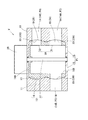
次に、バルブ装置Vの具体的な構造について、図2および図4(a)を参照しながら順次説明する。
なお、以下の説明では、図の上側および下側を、便宜上「上方、上段」および「下方、下段」と呼称するが、かかる呼称は車両搭載時における天方向および地方向を意味しているものではない。
[Basic configuration of valve device V]
Next, a specific structure of the valve device V will be sequentially described with reference to FIGS. 2 and 4A.
In the following description, the upper side and the lower side of the drawing are referred to as “upper and upper stages” and “lower and lower stages” for convenience, but such designations mean the upward direction and the downward direction when the vehicle is mounted. is not.
バルブ装置Vは、大別すると、ロータリ式バルブ10、および、このロータリ式バルブ10を回動操作するアクチュエータ20で構成されている。
The valve device V is roughly composed of a
ロータリ式バルブ10(以下、単に、バルブ10と略称する。)は、ハウジング11と弁体12を主要構成部品とし、内部に弁部30を有している。
A rotary valve 10 (hereinafter, simply referred to as a valve 10) has a
ハウジング11は、バルブ10の外筐をなすもので、実質的に円柱状孔を呈する弁体収容孔13、およびこの弁体収容孔13に対して径方向に配置され、異なる機器に冷却水を流通させる通路部14を備えている。
この通路部14は、第2〜第4流路P2〜P4に対応する3つの通路部14A、14B、14Cで構成され、このうち、2つの通路部14A、14Bが一段目をなす下段側に、残余の1つの通路部14Cが2段目をなす上段側にそれぞれ配設されている。
また、ハウジング11には、第1流路P1に接続され、冷却水を当該バルブ10内に導入するための共通流路部15が設けられている。
The
The
In addition, the
弁体12は、ハウジング11の弁体収容孔13に回動自在に収納され、前述の通路部14(14A〜14C)を開閉制御するもので、全体として円筒状を呈している。そして、弁体12は、円筒部16と回動軸17とを有しており、回動軸17でハウジング11に回動自在に支承されている。
円筒部16は、上端側に閉塞部16Aを有し下端側に開口部16Bを有する縦断面逆U字形をなしており、閉塞部16Aで回動軸17に固定されている。そして、下端側の開口部16Bが、ハウジング11の共通流路部15と連通し、円筒部16内に冷却水を導入する導入口をなしている。なお、以下の説明では便宜上、この開口部16Bを、円筒部16の内部空間の総称としても使用することがある(図3〜図5参照)。
また、円筒部16には、後述する弁部30の要の構成要素をなす弁穴(下段側開口穴18および上段側開口穴19)が設けられている。
The
The
Further, the
弁部30は、冷却水導入口(円筒部16の開口部16B)とハウジング11の通路部14との間を開閉するもので、ハウジング11と弁体12との間に構築された2つの弁部31、32を備えている。この2つの弁部31、32は、図3に示す弁体12側の外観で代表されるように、ハウジング11側と弁体12側との摺接面が曲面状に形成された所謂ボール弁構造をなしており、弁体12の回動軸線方向に沿って上下の2段に連なって配設されている。なお、下段側を第1弁部31、上段側を第2弁部32と呼称する。
The
下段側の第1弁部31は、2つの流路を開閉するものであり、ハウジング11側のポート33として設けられた2つの第1ポート33Aおよび第2ポート33Bと、この第1ポート33Aおよび第2ポート33Bを開閉するために弁体12側に設けられた第1弁穴34とを備えている。
第1ポート33Aおよび第2ポート33Bは、ハウジング11の弁体収容孔13の内壁面に設けられ、下段側の2つの通路部14A、14Bの開口端を形成しており、弁体12(円筒部16)を挟んで対向するように配置されている。
また、第1弁穴34は、前述した下段側開口穴18のことで、2つの開口穴(第1開口穴34Aおよび第2開口穴34B)で構成され、弁体12の円筒部16に対してこれを貫通するとともに周方向に延展して形成されている。
なお、第1開口穴34Aおよび第2開口穴34Bは、円筒部16の円周方向に相互に離隔して形成されており、第1ポート33Aおよび第2ポート33Bと開閉する
The
The
The
The
上段側の第2弁部32は、1つの流路を開閉するものであり、ハウジング11側に別のポート33として設けられた第3ポート33Cと、この第3ポート33Cを開閉するために弁体12側に設けられた第2弁穴35とを備えている。
第3ポート33Cは、ハウジング11の弁体収容孔13の内壁面に設けられ、上段側の残余の通路部14Cの開口端を形成している。
また、第2弁穴35は、前述した上段側開口穴19のことで、1つの長穴状開口穴35Aで構成されており、弁体12の円筒部16に対してこれを貫通するとともに周方向に幅広く(広角度に)延展して形成されている。
The
The
The
なお、弁部30は、上述ごとく、多数の開口穴を備えている。つまり、第1弁部31は、弁体12側の第1弁穴34をなす第1開口穴34Aおよび第2開口穴34Bと、ハウジング11側の第1ポート33A、第2ポート33Bをなす開口穴とを有している。第2弁部32は、弁体12側の第2弁穴35をなす長穴状開口穴35Aとハウジング11側の第3ポート33Cをなす開口穴とを有している。これらの開口穴は、いずれも、開口穴の回動方向に対する展開形状が四角形を呈している。かかる形状の詳細については、弁体12側を代表にして後述する。
The
アクチュエータ20は、図示しないコントローラ(例えば、車両の運転状態を制御する電子制御装置に組み込まれたECU)からの指令を受け、バルブ10の弁体12を時計周りと反時計周りとの2方向に回動操作するもので、弁体12の回動軸17に連結されている。
なお、このようなアクチュエータ20には、限定するものではないが、例えば、駆動源をなす正逆転可能なモータと、このモータの回転を減速して回動軸17に伝達する減速歯車装置とで構成される一般的な駆動機構を用いることができる。
The
Although not limited to such an
〔バルブ装置Vの基本作動〕
次に、上記構成において、バルブ装置Vの基本作動を説明する。
[Basic operation of valve device V]
Next, the basic operation of the valve device V in the above configuration will be described.
車両においては、冷却水が関係する運転状態として、ヒータHを使用しない〔第1の運転状態〕と、寒冷時のごとくヒータHを使用する〔第2の運転状態〕との2つの運転状態に大別される。そして、それぞれの運転状態に応じて、エンジンEの冷却水を冷却制御装置100で適切にコントロールすることになる。
In the vehicle, there are two operating states relating to the cooling water, that is, the heater H is not used [first operating state] and the heater H is used as in cold weather [second operating state]. Broadly divided. Then, the cooling water for the engine E is appropriately controlled by the cooling
〔第1運転状態〕
この運転状態での冷却制御装置100の使命は、第1流路P1と第2流路P2および第3流路P3とを連通させ、エンジンEの冷却水をウォータポンプWによりオイルクーラOおよびラジエータRへ流通させるとともに、第1流路P1と第4流路P4とを遮断し、冷却水がヒータHへ流通しないようにすることにある。
そのため、バルブ10は、第1弁部31が開弁して2つの流路部14A、14Bを開閉制御するとともに、第2弁部32が閉弁し、残余の流路部14Cを遮断している。
つまり、第1弁部31では、弁体12の第1弁穴34とハウジング11の第1ポート33Aおよび第2ポート33Bとが重合しその開口面積を変化させることで、弁体12の開口部16Bから円筒部16内に導入される冷却水をオイルクーラOおよびラジエータRへ流通させる。第2弁部32では、弁体12の第2弁穴35(長穴状開口穴35A)がハウジング11の第3ポート33Cと一切重合せず、円筒部16内に導入された冷却水を第3ポート33Cへは一切供給しないため、ヒータHへ冷却水が送られることはない。
[First operating state]
The mission of the
Therefore, in the
That is, in the
〔第2運転状態〕
この運転状態での冷却制御装置100の使命は、第1流路P1とすべての循環流路である第2流路P2〜第4流路P4とを連通させ、エンジンEの冷却水をオイルクーラOおよびラジエータRに加え、ヒータHへも循環させるようにすることにある。
そのため、バルブ10は、第1弁部31が開弁して2つの流路部14A、14Bへの冷却水量を制御するとともに、第2弁部32も開弁して残余の流路部14Cへの冷却水量を制御する。
つまり、第1弁部31では、弁体12の第1弁穴34とハウジング11の第1ポート33Aおよび第2ポート33Bとの開口面積を変化させることで、弁体12の開口部16Bから円筒部16内に導入される冷却水をラジエータRおよびオイルクーラOへ流通させる。同時に、第2弁部32では、弁体12の第2弁穴35がハウジング11の第3ポート33Cと重合するため、その開口面積を変化させることで、円筒部16内に導入された冷却水をヒータHへも供給する。
[Second operating state]
The mission of the
Therefore, in the
That is, in the
〔実施例1の特徴点1〕
ここで、上記の2つの運転状態に適合する冷却水制御を実行させるためには、バルブ10に構築する弁部30の構造を工夫する必要がある。かかる弁部構造の一例を図4および図5も参照しながら概説する。
[Characteristic point 1 of Embodiment 1]
Here, in order to execute the cooling water control suitable for the above-mentioned two operating states, it is necessary to devise the structure of the
図4および図5において、第1弁部31と第2弁部32との関係は、上記〔第1運転状態〕を矢印T1のごとく時計回りの回動操作で実行し、上記〔第2運転状態〕をその逆の矢印T2のごとく反時計回りの回動操作で実行できることが望ましい。
そのためには、第1弁部31では、時計回りT1、反時計回りT2の両回動方向でオイルクーラOおよびラジエータRへの流路を開閉制御することができるようにするとともに、第2弁部32は、例えば反時計回りT2のみの1回動方向でヒータHへの流路を開閉制御できるようにすることが肝要となる。
4 and 5, the relationship between the
To this end, the
したがって、第1弁部31では、弁体12の第1弁穴34として第1開口穴34Aと第2開口穴34Bとの2つの穴が、円筒部16に対して周方向に離隔して設けられている。そして、この2つの開口穴34A、34Bが、ハウジング11側の2つのポート33A、33Bに対して、時計回りT1と反時計回りT2との両回動方向でそれぞれ異なるポートと重合し開閉するようになっている。
また、第2弁部32では、弁体12の第2弁穴35として1つの長穴状開口穴35Aが円筒部16に設けられている。特に、この長穴状開口穴35Aは、反時計回りT2のみの1回動方向で、ハウジング11側の第3ポート33Cと長く連通し、ヒータH用の流路P4を全開状態に保持できるように、周方向に広い回動角度範囲(例えば180°)にわたって形成されている。
Therefore, in the
Further, in the
上記構成の弁部構造によれば、各運転状態毎に次のような制御機能が得られる。 According to the valve structure having the above configuration, the following control function can be obtained for each operating state.
〔第1運転状態〕では、バルブ10を時計回りT1に回動操作することで、第1弁部31および第2弁部32に図4に示すごとき動作が得られる。図4において、(a)は回動開始前の閉弁状態、(b)は第1の開弁状態、(c)は第2の開弁状態を示している。
In the [first operating state], by rotating the
まず、第1弁部31は、閉弁状態(a)から時計回りT1に回動すると、弁体12の第1開口穴34Aとハウジング11の第1ポート33Aとが重合し始め、その開口面積が全開まで増加していく第1の開弁状態(b)に移行する。これにより、オイルクーラO用の第2流路P2が形成される。そして、全開に達した後に弁体12の第2開口穴34Bとハウジング11の第2ポート33Bとが重合し始め、その開口面積が増加していく第2の開弁状態(c)に移行する。これにより、ラジエータR用の第3流路P3が形成される。なお、この第2の開弁状態では、両開口穴34A、34Bと両ポート33A、33Bとの開口面積が反比例するものの、共に開弁している。よって、オイルクーラO用の第2流路P2、ラジエータR用の第3流路P3が共に形成される。
First, when the
これに対し、第2弁部32は、弁体12の第2弁穴35が長穴状開口穴35Aであるものの、ハウジング11の第3ポート33Cとは一切重合しないため、閉弁状態のままである。したがって、ヒータH用の第4流路P4は形成されない。
かくして、バルブ10を時計回りT1に回動操作することで、冷却制御装置100において〔第1運転状態〕に適合した冷却水制御機能を得ることができる。
On the other hand, in the
Thus, by rotating the
次に、〔第2運転状態〕では、バルブ10を反時計回りT2に回動操作することで、第1弁部31に加え、第2弁部32にも開弁機能を発揮させることにより、図5に示すごとき動作が得られる。図5において、(a)は回動開始前の閉弁状態、(b)は第3の開弁状態、(c)は第4の開弁状態、(d)は第5の開弁状態を示している。
Next, in the [second operating state], by rotating the
まず、バルブ10は、反時計回りT2に回動操作されると第2弁部32が開弁し始め、第3の開弁状態(b)に示す全開状態へと移行する。つまり、弁体12の第2弁穴35(長穴状開口穴35A)とハウジング11の第3ポート33Cとが重合し始め、長穴状開口穴35Aが第3ポート33Cと完全に重合する。この間、第1弁部31は、閉弁状態を持続する。
そして、第2弁部32は、開口穴35Aが長穴状に形成されており、全開状態に達した後も全開状態を持続する。よって、第4開弁状態(c)→第5開弁状態(d)へと開弁状態が移行しても、全開状態のままである。これにより、ヒータH用の第4流路P4が形成され続ける。
First, when the
Further, the
これに対し、第1弁部31側では、第2弁部32が全開に達した後に開弁し始める第3の開弁状態(b)へ移行し、第4、第5の開弁状態(c)、(d)へと順次移行する。つまり、第3の開弁状態(b)では、弁体12の第2開口穴34Bとハウジング11の第1ポート33Aとが重合し始め、その開口面積が全開まで増加していく第4の開弁状態(c)に移行する。この開弁状態は、図4の第1開弁状態(b)と等価であり、オイルクーラO用の第2流路P2が形成される。
On the other hand, on the
その後に弁体12の第1開口穴34Aとハウジング11の第2ポート33Bとが重合し始め、その開口面積が増加していく第5の開弁状態(d)に移行する。この開弁状態は、図4の第2開弁状態(c)と等価であり、ラジエータR用の第3流路P3が形成される。なお、この第5状態(d)では、両開口穴34A、34Bと両ポート33A、33Bとの開口面積が反比例するものの、共に開弁しているため、オイルクーラO用の第2流路P2と、ラジエータR用の第3流路P3が共に形成される。
かくして、バルブ10を反時計周りT2に回動操作することで、冷却制御装置100において〔第2運転状態〕に適合した冷却水制御機能を得ることができる。
After that, the
Thus, by rotating the
〔実施例1の特徴点2〕
また、上記の2つの運転状態に対して実用的に適合させるためには、制御上次の3つの条件がバルブ10に課せられる。
○第1には、開閉タイミングが近い弁部間においては開弁開始位置の間隔(回動角に相当する)にできるだけ余裕を持たせ得ること(以下、「余裕度条件」と呼ぶ)。
つまり、各構成部品には製作誤差、交差等による寸法のバラツキが必然的に伴なうことから、このバラツキを吸収するためには、上記間隔に余裕度を必要とする。
○第2には、複数の機器に対して冷却水を熱媒体として有効活用するための開弁順序に制約が伴なうこと(以下、「開弁順序条件」と呼ぶ)。
例えば、ラジエータRへの流路は冷却水を冷却させるためであることから、最後に開弁させることが望ましい。
○第3には、配管の関係でオイルクーラOとラジエータRとに流れる冷却水量の総和を一定にすること(以下、「流量一定条件」と呼ぶ)。
[
Further, in order to be practically adapted to the above two operating states, the following three conditions are imposed on the
Firstly, the valve opening start position interval (corresponding to the turning angle) can be provided with as much margin as possible between the valve portions having close opening and closing timings (hereinafter, referred to as "margin condition").
In other words, each component inevitably involves variations in dimensions due to manufacturing errors, intersections, etc. Therefore, in order to absorb this variation, a margin is required for the above-mentioned interval.
Secondly, there is a restriction on the valve opening order for effectively utilizing cooling water as a heat medium for a plurality of devices (hereinafter, referred to as "valve opening order condition").
For example, since the flow path to the radiator R is for cooling the cooling water, it is desirable to open the valve last.
Thirdly, the total sum of the amounts of cooling water flowing through the oil cooler O and the radiator R is made constant due to the relationship of the pipes (hereinafter, referred to as "a constant flow rate condition").
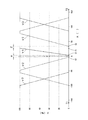
本実施例で用いるバルブ10は、上記の3条件を満足するものであり、以下、かかる3条件を如何に満足するかのメカニズムについて、バルブ10の全開口穴の開閉タイミングと開閉条件を示す図6を参照しながら概説する。
The
図6において、横軸は、弁体12の回動角度X〔°〕を示しており、0°を基点として左側のマイナス(−)表示が「時計回りT1」に回動した場合、右側の数値表示のみが「反時計回りT2」に回動した場合をそれぞれ表している。縦軸は、各弁部の開弁率Y〔%〕を示しており、0%が「全閉状態」、100%が「全開状態」を表している。
そして、実線の特性がヒータH用の開弁特性V1、破線の特性がオイルクーラO用の開弁特性V2、1点鎖線の特性がラジエータR用の開弁特性V3を、それぞれ示している。
In FIG. 6, the horizontal axis indicates the rotation angle X [°] of the
The solid line characteristic shows the valve opening characteristic V1 for the heater H, the broken line characteristic shows the valve opening characteristic V2 for the oil cooler O, and the dashed line characteristic shows the valve opening characteristic V3 for the radiator R, respectively.
上記図6から明らかなように、本実施例のバルブ10は、時計回りT1の回動方向で開弁特性V2、V3を順次発揮し、反時計回りT2の回動方向で開弁特性V1〜V3を順次発揮するように設定されている。
そして、第1には、時計回りT1の開弁特性V2の開弁開始位置S2と反時計回りT2の開弁特性V1の開弁開始位置S1とが重なることがないように、両位置S1、S2間には所要の間隔(回動角)αが設定されている。また、反時計回りT2において、開弁特性V2の開弁開始位置S3と開弁特性V1の開弁終了位置F1とが重なることがないように、両位置S3、F1間には所要の間隔(回動角)βが設定されている。かくして、第1の「余裕度条件」を満足している。
As is apparent from FIG. 6, the
And firstly, both positions S1, so that the valve opening start position S2 of the valve opening characteristic V2 of the clockwise T1 and the valve opening start position S1 of the valve opening characteristic V1 of the counterclockwise T2 do not overlap. A required interval (rotation angle) α is set between S2. Further, in the counterclockwise direction T2, in order to prevent the valve opening start position S3 of the valve opening characteristic V2 and the valve opening end position F1 of the valve opening characteristic V1 from overlapping with each other, a required distance between the positions S3 and F1 ( The rotation angle) β is set. Thus, the first "margin condition" is satisfied.
また、第2には、時計回りT1において、2つの開弁特性が特性V2、V3の順で発揮されるとともに、反時計回りT2において、3つの開弁特性が特性V1、特性V2、特性V3の順で発揮されるように設定されている。したがって、〔第1運転状態〕では、オイルクーラO、ラジエータRの順で冷却水が流れ、〔第2運転状態〕では、ヒータH、オイルクーラO、ラジエータRの順で冷却水が流れる。かくして、第2の「開弁順序条件」を
満足している。
さらに、第3には、時計回りT1、反時計回りT2の両回動方向において、開弁特性V2と開弁特性V3とが、開弁率Yが反比例するように交差している。したがって、オイルクーラOとラジエータRとを流れる冷却水の流量の総和は一定となる。かくして、第3の「流量一定条件」を満足している。
Secondly, in the clockwise direction T1, the two valve opening characteristics are exhibited in the order of the characteristics V2 and V3, and in the counterclockwise direction T2, the three valve opening characteristics are the characteristic V1, the characteristic V2 and the characteristic V3. It is set to be demonstrated in order of. Therefore, in the [first operating state], the cooling water flows in the order of the oil cooler O and the radiator R, and in the [second operating state], the cooling water flows in the order of the heater H, the oil cooler O, and the radiator R. Thus, the second "valve opening sequence condition" is satisfied.
Further, thirdly, the valve opening characteristic V2 and the valve opening characteristic V3 intersect such that the valve opening ratio Y is inversely proportional in both clockwise and counterclockwise T2 rotational directions. Therefore, the total sum of the flow rates of the cooling water flowing through the oil cooler O and the radiator R becomes constant. Thus, the third "constant flow rate condition" is satisfied.
〔実施例1の特徴点3〕
この特徴点3は、上記の特徴点1、2を効果的に実現するための基礎をなすもので、弁部30に設ける開口穴の形状を工夫し、各開口穴の回動方向に対する展開形状を四角形にした点にある。
[
The
本実施例では、すべての開口穴を四角形状に形成しており、弁体12側を代表して図3により補足説明する。
弁体12において、第1、第2の弁穴34、35に設ける開口穴は、いずれも、図3(b)、(c)に示す楕円形状の丸穴34C、長穴35Bや真円形状の穴34D、35Cではなく、図3(a)に示すごとき四角形状、とりわけ、その代表形である四隅がピン角(直角)を有する四角形にしている。そして、第2の弁穴35は、回動角度範囲(開口角)を大きく必要とする長穴であるため、長方形状の長穴35Aに形成せざるを得ないが、第1の弁穴34は、2つの開口穴の回動角度範囲(開口角)がいずれも小さいため、第1開口穴34Aおよび第2開口穴34Bを共に正方形に形成することができる。もっとも、第2の弁穴35側においても、長方形状長穴35Aとはいえ、全閉から全開に至る回動範囲XAの領域を正方形にすることができる。
なお、ハウジング11側のポート33A〜33Cは、図示を省略しているが、いずれも同一形状でかつ小さな開口角で良いため、四角形として、いずれも、第1開口穴34Aおよび第2開口穴34Bと同様に正方形に形成することができる。
In this embodiment, all the opening holes are formed in a quadrangular shape, and a supplementary explanation will be given with reference to FIG.
In the
Although the
本実施例の矩形状開口穴が優れた制御機能を発揮することについて、図7を参照しながら説明する。 It will be described with reference to FIG. 7 that the rectangular opening hole of this embodiment exerts an excellent control function.
図7は、弁部30に設ける開口穴の展開形状を種々変更して、同一の最大流通面積を確保するための開弁側特性を比較したものである。かかる図7は、全閉状態(Y=0%)から全開状態(Y=100%)に至るまでの開弁側特性を、3種の展開穴形状について対比しており、特性Aは図3(a)の四角形状にした場合、特性Bは図3(b)の回動軸線方向に長軸を有する楕円形状にした場合、特性Cは図3(c)の真円形状にした場合をそれぞれ示している。
FIG. 7 is a comparison of valve opening side characteristics for securing the same maximum distribution area by variously changing the developed shape of the opening hole provided in the
図7から明らかなように、楕円形状および真円形状の場合には、回動角度Xに応じてハウジング11側のポート33A〜33Cと重合する穴形状が変化し、単位回動角あたりの開口面積が小→大→小と変化していくため、広範囲の回動角度Xb、Xcにわたって開弁率Yが緩やかに増大していく特性B,Cが得られる。
これに対し、矩形状の場合には、回動角度Xに応じてハウジング11側のポート33A〜33Cと重合する形状の変化が一定で、単位回動角あたりの開口面積が一定量で増大していくため、小さい回動角度Xaで全開状態(Y=100%)に到達する直線的な特性Aが得られる。
As is clear from FIG. 7, in the case of the elliptical shape and the perfect circle shape, the hole shape overlapping with the
On the other hand, in the case of the rectangular shape, the change of the shape overlapping with the
本実施例の弁部30には開弁側特性として上記特性Aを発揮するようにしているため、制御機能上次のごとき利点が得られる。
〔利点1〕
開口穴1つ当たりの円周方向スペース、つまり、全閉状態(Y=0°)〜全開状態(Y=100°)に要する回動角度Xaを小さくすることができ、弁体12(円筒部16)の1回転(360°)を有効活用して、複数の開口穴を開閉させることができる。
また、小さな回動角度Xaは、時間軸に換算すると開閉に要する時間を短縮できるため、制御スピードを高めることができる。
〔利点2〕
円筒部16の円周方向に複数の開口穴を容易に設けることができることにより、弁部30を時計回りT1と反時計回りT2との両方向に回動させて流路を制御することが可能となる。
また、弁部30を多段構造に構築しても、「余裕度条件」を満足し、各段部31、32の開弁開始位置がオーバーラップする事態を回避することができる。
Since the
[Advantage 1]
The circumferential space per one opening hole, that is, the rotation angle Xa required from the fully closed state (Y=0°) to the fully opened state (Y=100°) can be reduced, and the valve body 12 (cylindrical portion). By effectively utilizing one rotation (360°) of 16), it is possible to open and close a plurality of opening holes.
Further, when the small rotation angle Xa is converted into the time axis, the time required for opening and closing can be shortened, so that the control speed can be increased.
[Advantage 2]
Since it is possible to easily provide a plurality of opening holes in the circumferential direction of the
Further, even if the
〔実施例1の効果〕
上述した実施例1によるバルブ装置Vにおいては、次のような作用効果を奏する。
[Effect of Example 1]
The valve device V according to the first embodiment described above has the following operational effects.
(1)ロータリ式のバルブ10において、特徴点3として詳説したように、弁部30の開口穴の形状を工夫している。具体的には、第1弁部31および第2弁部32において、弁体12側およびハウジング11側に設けるすべての開口穴を、開口穴の回動方向に対する展開形状が四角形を呈するようにしている。
四角形状の開口穴は、単位回動角あたりの開口面積変化量が一定で、小さい回動角度で大きな流通面積を確保することが可能となるため、1回転(360°)を有効活用して異なる流路の開閉制御を実行させることができる。したがって、バルブ10の径方向寸法を小さくすることが可能である。
(2)特に、四隅がピン角(直角)の四角形にすることにより、開弁開始直後からの単位回動角あたりの開口面積を最大にすることができ、開口穴1つ当たりの円周方向スペースを最小にすることができる。四角形のなかでも、とりわけ正方形は、最小の周囲長で最大の面積を確保できる形状であるため、すべての開口穴について全閉から全開に至る回動範囲XAの領域を正方形状に形成することで、開口穴1つ当たりの円周方向スペースの最小化をより一層促進することができる。
(3)第1弁部31の開弁開始位置と第2弁部32の開弁開始位置とを周方向において重畳させることなく容易にずらせることができ、これを活用して、各段の流路配置構成を工夫している。具体的には、第1弁部31において少なくとも2つの流路P2、P3を制御し、第2弁部32で他の流路P4を独立に制御しており、軸方向に圧縮した流路配置構成を実現している。したがって、バルブ10の軸方向寸法を小さくしながら、多数の流路の開閉制御を達成することができる。
(4)また、バルブ10を時計方向T1と反時計方向T2との両回動方向に操作することで流路制御することができるため、バルブ10の径方向および軸方向の両寸法を一層小さくすることができる。
(5)上述のごとくバルブ10を小型にすることができるため、当該バルブ10を回動操作するアクチュエータ20も必然的に小容量で外形の小さい小型軽量のものにすることができる。
(6)かくして、軸方向および径方向の外形を小さくしながら、多数の流路の開閉制御を達成することができる小型軽量のバルブ装置Vを提供することができる。
(1) In the
The square opening hole has a constant amount of change in the opening area per unit rotation angle, and a large distribution area can be secured at a small rotation angle. Therefore, one rotation (360°) is effectively used. It is possible to execute opening/closing control of different flow paths. Therefore, the radial dimension of the
(2) In particular, by making the four corners a quadrangle with pin angles (right angles), it is possible to maximize the opening area per unit rotation angle immediately after the opening of the valve, and the circumferential direction per opening hole. Space can be minimized. Among the quadrilaterals, particularly the square is a shape that can secure the maximum area with the minimum perimeter. Therefore, by forming the area of the rotation range XA from the fully closed to the fully open for all the opening holes in the square shape. The minimization of the circumferential space per opening hole can be further promoted.
(3) The valve opening start position of the
(4) Further, since the flow path can be controlled by operating the
(5) Since the
(6) Thus, it is possible to provide a small and lightweight valve device V capable of achieving opening/closing control of a large number of flow paths while reducing the outer shape in the axial direction and the radial direction.
〔他の実施形態;変形例〕
以上、本発明を一実施例について詳述してきたが、本発明の精神を逸脱しない範囲で種々変形することが可能であり、他の実施形態としてその変形例を例示する。
[Other Embodiments; Modifications]
Although the present invention has been described in detail above with respect to one embodiment, various modifications can be made without departing from the spirit of the present invention, and other modifications will be exemplified.
(1)実施例1では、第1弁部31および第2弁部32の双方における開口穴形状をすべて四角形にしたが、第2弁部側32は1つでかつ広角を有する長穴状の開口穴35Aであるため、開弁開始側の穴形状を四角形以外の適宜形状にすることも可能である。
(2)実施例1では、代表的な四角形として、四隅がピン角(直角)を有する四角形にしたが、四隅には必要な面取りを施しても良い。
(3)また、弁部30の段数、各段の通路数や通路部の配置についても、実施例1に何ら限定されるものではなく、用途や制御態様に応じて種々変更することができることは勿論
である。
(1) In the first embodiment, all the opening hole shapes in both the
(2) In the first embodiment, as a typical quadrangle, a quadrangle with four corners having pin angles (right angles) is used, but the four corners may be chamfered as necessary.
(3) Further, the number of stages of the
(4)以上の実施形態では、本発明のバルブ装置および流体制御装置を車両用エンジンの冷却制御装置に適用した例について詳説したが、これに限定されるものではなく、ロータリ式バルブを用いて複数の流路を開閉制御する流体制御システムに広く適用することができる。 (4) In the above embodiments, an example in which the valve device and the fluid control device of the present invention are applied to a vehicle engine cooling control device has been described in detail. However, the present invention is not limited to this, and a rotary valve is used. It can be widely applied to a fluid control system that controls opening and closing of a plurality of flow paths.
10…ロータリ式バルブ、11…ハウジング、12…弁体、13…弁体収納孔、14…通路部、14A…第1通路部、14B…第2通路部、14C…第3通路部、16…円筒部、16B…開口部(導入口)、20…アクチュエータ、30…弁部、31…第1弁部、32…第2弁部、33A…第1ポート、33B…第2ポート、33C…第3ポート、34…第1弁穴、34A…第1開口穴、34B…第2開口穴、35…第2弁穴、35A…長穴状開口穴、100…冷却制御装置(流体制御装置)、E…エンジン、H…ヒータ(機器)、O…オイルクーラ(機器)、R…ラジエータ(機器)、V…バルブ装置。
DESCRIPTION OF
Claims (23)
前記ハウジングは、冷却水を冷却するラジエータ(R)および前記冷却水を車室内暖房の熱源とするヒータ(H)を迂回する冷却水流路(P2)と接続する第1ポート(33A)、前記ラジエータの配される冷却水流路(P3)と接続する第2ポート(33B)、ならびに、前記ヒータの配される冷却水流路(P4)と接続する第3ポート(33C)を有し、
前記ロータリ式バルブは、前記弁体の円筒部内に流体を導入する導入口(16B)と、この導入口と前記通路部とを接続する複数の弁穴(34、34A、34B、35、35A)とを備える弁部(30)を有し、
前記第3ポートが全開状態に保持されている場合に、前記第1ポートと前記第1ポートと連通する前記複数の弁穴の一つである第1開口穴(34A)の開口面積と前記第2ポートと前記第2ポートと連通する前記複数の弁穴の一つである第2開口穴(34B)の開口面積の一方の開口面積が増加すると他方の開口面積が減少するように前記弁部が回転することを特徴とするバルブ装置。 A valve body housing hole (13) and a housing (11) having a plurality of passage portions (14, 14A, 14B, 14C) arranged in a radial direction with respect to the valve body housing hole and allowing fluid to flow, and the valve body. A rotary valve (10) rotatably housed in a housing hole and including a valve body (12) for controlling opening and closing of the passage portion, and a rotary valve mounted on the rotary valve to rotate the valve body. In a valve device (V) equipped with an actuator (20),
The housing has a first port (33A) connected to a radiator (R) that cools cooling water and a cooling water flow path (P2) that bypasses a heater (H) that uses the cooling water as a heat source for heating the passenger compartment, the radiator. A second port (33B) connected to the cooling water flow path (P3) in which the heater is arranged, and a third port (33C) connected to the cooling water flow path (P4) in which the heater is arranged,
The rotary valve has an inlet (16B) for introducing a fluid into the cylindrical portion of the valve body, and a plurality of valve holes (34, 34A, 34B, 35, 35A) connecting the inlet and the passage. A valve section (30) comprising
When the third port is held in a fully opened state, the opening area of the first opening hole (34A), which is one of the plurality of valve holes communicating with the first port and the first port, and the first opening hole (34A). The valve portion so that when one opening area of the second opening hole (34B), which is one of the plurality of valve holes communicating with the two ports and the second port, increases, the other opening area decreases. A valve device characterized in that the valve rotates.
前記ハウジングは、冷却水を冷却するラジエータ(R)および前記冷却水を車室内暖房の熱源とするヒータ(H)を迂回する冷却水流路(P2)と接続する第1ポート(33A)、前記ラジエータの配される冷却水流路(P3)と接続する第2ポート(33B)、ならびに、前記ヒータの配される冷却水流路(P4)と接続する第3ポート(33C)を有し、
前記ロータリ式バルブは、前記弁体の円筒部内に流体を流通させる開口部(16B)と、この開口部と前記通路部とを接続する複数の弁穴(34、34A、34B、35、35A)とを備える弁部(30)を有し、
前記第3ポートが全開状態に保持されている場合に、前記第1ポートと前記第1ポートと連通する前記複数の弁穴の一つである第1開口穴(34A)の開口面積と前記第2ポートと前記第2ポートと連通する前記複数の弁穴の一つである第2開口穴(34B)の開口面積の一方の開口面積が増加すると他方の開口面積が減少するように前記弁部が回転し、前記第1開口穴と前記第2開口穴は、前記弁部の周方向に相互に離隔して形成されていることを特徴とするバルブ装置。 A valve body housing hole (13) and a housing (11) having a plurality of passage portions (14, 14A, 14B, 14C) arranged in a radial direction with respect to the valve body housing hole and allowing fluid to flow, and the valve body. A rotary valve (10) rotatably housed in a housing hole and including a valve body (12) for controlling opening and closing of the passage portion, and a rotary valve mounted on the rotary valve to rotate the valve body. In a valve device (V) equipped with an actuator (20),
The housing has a first port (33A) connected to a radiator (R) that cools cooling water and a cooling water flow path (P2) that bypasses a heater (H) that uses the cooling water as a heat source for heating the passenger compartment, the radiator. A second port (33B) connected to the cooling water flow path (P3) in which the heater is arranged, and a third port (33C) connected to the cooling water flow path (P4) in which the heater is arranged,
The rotary valve includes an opening (16B) for allowing a fluid to flow in the cylindrical portion of the valve body, and a plurality of valve holes (34, 34A, 34B, 35, 35A) connecting the opening and the passage. A valve section (30) comprising
When the third port is held in a fully opened state, the opening area of the first opening hole (34A), which is one of the plurality of valve holes communicating with the first port and the first port, and the first opening hole (34A). The valve portion so that when one opening area of the second opening hole (34B), which is one of the plurality of valve holes communicating with the two ports and the second port, increases, the other opening area decreases. There is rotated, wherein the first opening hole second opening hole, a valve device which is characterized that you have been spaced apart from each other in the circumferential direction of the valve portion.
前記導入口または前記開口部から前記円筒部内に導入された流体が前記複数の弁穴を介して前記通路部へと送られることを特徴とするバルブ装置。 The valve device according to claim 1 or 2,
A valve device, wherein fluid introduced into the cylindrical portion from the inlet or the opening is sent to the passage portion through the plurality of valve holes .
前記第3ポートに前記冷却水を供給しない第1運転状態と、
前記第3ポートに前記冷却水を供給する第2運転状態とを備え、
前記第1運転状態は、前記第1ポートおよび前記第2ポートへ前記冷却水を供給しない閉弁状態と、
前記第1ポートへ前記冷却水を供給し、前記第2ポートへ前記冷却水を供給しない第1開弁状態と、
前記第1ポートおよび前記第2ポートへ前記冷却水を供給する第2開弁状態を有することを特徴とするバルブ装置。 The valve device according to any one of claims 1 to 3,
A first operating state in which the cooling water is not supplied to the third port,
A second operating state in which the cooling water is supplied to the third port,
The first operating state is a valve closed state in which the cooling water is not supplied to the first port and the second port,
A first valve open state in which the cooling water is supplied to the first port and the cooling water is not supplied to the second port;
A valve device having a second valve open state in which the cooling water is supplied to the first port and the second port .
前記第2運転状態は、前記第1ポートへ前記冷却水を供給し、前記第2ポートへ前記冷却水を供給しない第4開弁状態と、
前記第1ポートおよび前記第2ポートへ前記冷却水を供給する第5開弁状態とを有することを特徴とするバルブ装置。 The valve device according to claim 4 ,
In the second operation state, a fourth valve open state in which the cooling water is supplied to the first port and the cooling water is not supplied to the second port,
A fifth valve opening state in which the cooling water is supplied to the first port and the second port .
前記第1運転状態は、前記第1ポートへ前記冷却水を供給せず、前記第2ポートへ前記冷却水を供給する第6開弁状態を有し、
前記第2運転状態は、前記第1ポートへ前記冷却水を供給せず、前記第2ポートへ前記冷却水を供給する第7開弁状態とを有することを特徴とするバルブ装置。 The valve device according to claim 5 ,
The first operating state has a sixth valve open state in which the cooling water is not supplied to the first port and the cooling water is supplied to the second port,
It said second operating condition, wherein the first port without supplying the cooling water, the valve device according to claim Rukoto which have a and seventh open state for supplying the cooling water to the second port.
前記第2運転状態は、前記第1ポートおよび前記第2ポートへ前記冷却水を供給しない第3開弁状態を有することを特徴とするバルブ装置。 The valve device according to any one of claims 4 to 6,
Said second operating condition, the valve device according to claim Rukoto that having a third open state without supplying the cooling water to said first port and said second port.
前記第3ポートが全開状態に保持されている場合に、前記第2ポートと前記第2開口穴の開口面積が増加または減少するように前記弁部が回転することを特徴とするバルブ装置。 The valve device according to any one of claims 1 to 7,
When said third port is held in the fully opened state, the valve device where the valve portion so that to increase or decrease the opening area between the second port and the second opening hole, characterized in that the rotating.
前記第3ポートが全開状態に保持されている場合に、前記第2ポートと前記第2開口穴の開口面積が全開状態から全閉状態になるように前記弁部が回転することを特徴とするバルブ装置。 The valve device according to any one of claims 1 to 8,
And wherein the third port is if it is held in the fully open state, the valve unit such that the opening area is fully closed from the fully open state and the second port and the second opening hole is rotated Valve device to do.
前記第3ポートが全開状態に保持されている場合に、前記第2ポートと前記第2開口穴の開口面積が全開状態になるように前記弁部が回転することを特徴とするバルブ装置。 The valve device according to any one of claims 1 to 9,
When said third port is held in the fully opened state, the valve device wherein the valve portion such that the opening area is fully opened state of the second port and the second opening hole characterized that you rotate.
前記第3ポートが全開状態に保持されている場合に、前記第2ポートと前記第2開口穴の開口面積が全閉状態から全開状態になるように前記弁部が回転することを特徴とするバルブ装置。 The valve device according to any one of claims 1 to 10,
When said third port is held in the fully open state, the opening area between the second port and the second opening hole and features that you said valve unit is rotated so as to fully open from the fully closed state Valve device to do.
前記第3ポートに前記冷却水を供給しない第1運転状態と、
前記第3ポートに前記冷却水を供給する第2運転状態とを備え、
前記第1運転状態と前記第2運転状態の少なくとも一方において、
前記第1ポートと前記第1開口穴の開口面積と前記第2ポートと前記第2開口穴の開口面積の一方の開口面積が増加すると他方の開口面積が減少するように前記弁部が回転する間、前記第1ポートと前記第2ポートとを流れる前記冷却水の水量の総和が一定であることを特徴とするバルブ装置。 The valve device according to any one of claims 1 to 11,
A first operating state in which the cooling water is not supplied to the third port,
A second operating state in which the cooling water is supplied to the third port,
In at least one of the first operating state and the second operating state,
The valve portion rotates so that when the opening area of one of the first port and the first opening hole and the opening area of one of the second port and the second opening hole increases, the other opening area decreases. during the valve device the sum of water volume of the cooling water flowing through said first port and said second port and said constant der Rukoto.
前記第3ポートと連通する前記複数の弁穴の一つである第3開口穴(35A)は長穴状開口穴であることを特徴とするバルブ装置。 The valve device according to any one of claims 1 to 12 ,
The third port and the third opening hole which is one of the plurality of valves holes communicating (35A) is a valve and wherein the elongated hole-like opening hole der Rukoto.
前記ハウジングは、前記ロータリ式バルブ内に冷却水を導入するための共通流路部(15)を有し、
前記弁体は、円筒部(16)と回転軸(17)を有し、
前記円筒部は、一端側に閉塞部(16A)と他端側に開口部(16B)を有し、前記開口部(16B)と共通流路部(15)とが連通することを特徴とするバルブ装置。 The valve device according to any one of claims 1 to 13 ,
The housing has a common flow passage portion (15) for introducing cooling water into the rotary valve,
The valve body has a cylindrical portion (16) and a rotating shaft (17),
The cylindrical portion is closed at one end side (16A) and opening at the other end has a (16B), and wherein Rukoto said opening and (16B) common passage section (15) is passed through communication Valve device to do.
前記第2運転状態は、前記第1ポートおよび前記第2ポートへ前記冷却水を供給しない第3開弁状態を有し、
前記弁体の回転により、前記第6開弁状態、前記第2開弁状態、前記第1開弁状態、前記閉弁状態、前記第3開弁状態、前記第4開弁状態、前記第5開弁状態、および、前記第7開弁状態が、この順序で実現されることを特徴とするバルブ装置。 The valve device according to claim 6 ,
The second operation state has a third valve open state in which the cooling water is not supplied to the first port and the second port,
By the rotation of the valve body, the sixth valve open state, the second valve open state, the first valve open state, the valve closed state, the third valve open state, the fourth valve open state, the fifth valve open state. open state, and the seventh opening state, the valve device according to claim Rukoto be implemented in this order.
前記第1開口穴と前記第2開口穴は、前記弁部の周方向に相互に離隔して形成されており、かつ、回転軸方向における相互に重複する位置関係にあり、
前記第3開口穴は、回転軸方向に前記第1開口穴および前記第2開口穴から離れた位置にあり、
前記第3開口穴の前記弁体における周方向の長さは、前記第1開口穴および前記第2開口穴より長く形成されていることを特徴とするバルブ装置。 The valve device according to claim 13 ,
The first opening hole and the second opening hole are formed so as to be separated from each other in the circumferential direction of the valve portion, and have a positional relationship of mutually overlapping in the rotation axis direction,
The third opening hole is at a position apart from the first opening hole and the second opening hole in the rotation axis direction,
The valve device is characterized in that a circumferential length of the third opening hole in the valve body is formed longer than the first opening hole and the second opening hole .
前記弁体は、前記アクチュエータにより時計回り(T1)と反時計回り(T2)との2方向に回動操作されるものであり、
前記弁体の時計回りの回動による前記第1ポートまたは前記第2ポートの開弁開始位置(S2)と、前記弁体の反時計回りの回動による前記第3ポートの開弁開始位置(S1)とが、周方向において相互に離隔して設けられていることを特徴とするバルブ装置。 The valve device according to claim 16 ,
The valve element is rotated by the actuator in two directions, clockwise (T1) and counterclockwise (T2),
A valve opening start position (S2) of the first port or the second port due to clockwise rotation of the valve body, and a valve opening start position (S2) of the third port due to counterclockwise rotation of the valve body ( S1) is provided so as to be separated from each other in the circumferential direction .
前記弁体の周方向における前記複数の弁穴の端部は、軸方向に延びていることを特徴とするバルブ装置。 The valve device according to any one of claims 1 to 17,
The valve device, wherein ends of the plurality of valve holes in the circumferential direction of the valve body extend in the axial direction .
前記第3ポートが閉弁状態から開弁状態となるのに要する前記弁体の回動角度は、
前記第1ポートが閉弁状態から開弁状態となるのに要する前記弁体の回動角度よりも小さいことを特徴とするバルブ装置。 The valve device according to any one of claims 1 to 18,
The rotation angle of the valve element required to change the third port from the valve closed state to the valve opened state is
A valve device, wherein the first port is smaller than a turning angle of the valve body required to change from a valve closed state to a valve opened state .
前記第3ポートが閉弁状態から開弁状態となるのに要する前記弁体の回動角度は、
前記第2ポートが閉弁状態から開弁状態となるのに要する前記弁体の回動角度よりも小さいことを特徴とするバルブ装置。 The valve device according to any one of claims 1 to 19,
The rotation angle of the valve element required to change the third port from the valve closed state to the valve opened state is
A valve device, wherein the second port is smaller than a rotation angle of the valve body required to change from a valve closed state to a valve opened state .
前記弁体は、前記アクチュエータにより時計回り(T1)と反時計回り(T2)との2方向に回動操作されるものであることを特徴とするバルブ装置。A valve device, wherein the valve element is operated to rotate in two directions of clockwise (T1) and counterclockwise (T2) by the actuator.
冷却水を冷却するラジエータ(R)および前記冷却水を車室内暖房の熱源とするヒータ(H)を迂回する冷却水流路(P2)に潤滑油と熱交換させる熱交換器が配されることを特徴とするバルブ装置。A radiator (R) for cooling the cooling water and a heat exchanger for exchanging heat with the lubricating oil are arranged in the cooling water flow path (P2) bypassing the heater (H) that uses the cooling water as a heat source for heating the vehicle interior. Characteristic valve device.
前記ハウジングは、前記ロータリ式バルブ内に冷却水を導入するための共通流路部(15)を有し、The housing has a common flow passage portion (15) for introducing cooling water into the rotary valve,
前記弁体は、円筒部(16)と回転軸(17)を有し、The valve body has a cylindrical portion (16) and a rotating shaft (17),
前記円筒部は、一端側に閉塞部(16A)と他端側に開口部(16B)を有し、The cylindrical portion has a closing portion (16A) on one end side and an opening portion (16B) on the other end side,
前記共通通路部と前記開口部とは前記弁部の回転位置に関わらず連通し、The common passage portion and the opening portion communicate with each other regardless of the rotational position of the valve portion,
前記共通通路部は前記円筒部の側面と対向していないことを特徴とするバルブ装置。The valve device, wherein the common passage portion does not face a side surface of the cylindrical portion.
Priority Applications (1)
| Application Number | Priority Date | Filing Date | Title |
|---|---|---|---|
| JP2018242127A JP6705494B2 (en) | 2018-12-26 | 2018-12-26 | Valve device and fluid control device |
Applications Claiming Priority (1)
| Application Number | Priority Date | Filing Date | Title |
|---|---|---|---|
| JP2018242127A JP6705494B2 (en) | 2018-12-26 | 2018-12-26 | Valve device and fluid control device |
Related Parent Applications (1)
| Application Number | Title | Priority Date | Filing Date |
|---|---|---|---|
| JP2015118536A Division JP6459787B2 (en) | 2015-06-11 | 2015-06-11 | Valve device and fluid control device |
Publications (3)
| Publication Number | Publication Date |
|---|---|
| JP2019066046A JP2019066046A (en) | 2019-04-25 |
| JP2019066046A5 JP2019066046A5 (en) | 2019-10-24 |
| JP6705494B2 true JP6705494B2 (en) | 2020-06-03 |
Family
ID=66340414
Family Applications (1)
| Application Number | Title | Priority Date | Filing Date |
|---|---|---|---|
| JP2018242127A Active JP6705494B2 (en) | 2018-12-26 | 2018-12-26 | Valve device and fluid control device |
Country Status (1)
| Country | Link |
|---|---|
| JP (1) | JP6705494B2 (en) |
Family Cites Families (5)
| Publication number | Priority date | Publication date | Assignee | Title |
|---|---|---|---|---|
| JP2003021246A (en) * | 2001-07-06 | 2003-01-24 | Sekisui Chem Co Ltd | Mixing valve |
| FR2827359B1 (en) * | 2001-07-11 | 2004-11-05 | Valeo Thermique Moteur Sa | CONTROL VALVE FOR A COOLING CIRCUIT OF A MOTOR VEHICLE HEAT ENGINE |
| US6681805B2 (en) * | 2001-11-28 | 2004-01-27 | Ranco Incorporated Of Delaware | Automotive coolant control valve |
| JP4029638B2 (en) * | 2002-03-18 | 2008-01-09 | 株式会社デンソー | Cooling device for heat generating equipment |
| JP2006029113A (en) * | 2004-07-12 | 2006-02-02 | Denso Corp | Cooling water flow control valve |
-
2018
- 2018-12-26 JP JP2018242127A patent/JP6705494B2/en active Active
Also Published As
| Publication number | Publication date |
|---|---|
| JP2019066046A (en) | 2019-04-25 |
Similar Documents
| Publication | Publication Date | Title |
|---|---|---|
| JP6459787B2 (en) | Valve device and fluid control device | |
| US10458562B2 (en) | Control valve | |
| JP6846083B2 (en) | Valve and cooling water circulation system | |
| US20200173566A1 (en) | Control valve | |
| US10359121B2 (en) | Control valve | |
| US10690040B2 (en) | Flow control valve and method of controlling the same | |
| JP6134129B2 (en) | Vehicle heat exchanger | |
| US9810136B2 (en) | Coolant-control valve | |
| JP6357038B2 (en) | Engine with multi-flow control valve | |
| CN111120695B (en) | Flow control valve | |
| US9650943B2 (en) | Rotary valve | |
| JP6501641B2 (en) | Flow control valve | |
| JP5694712B2 (en) | Oil cooler | |
| WO2015163181A1 (en) | Cooling control device, flow rate control valve and cooling control method | |
| KR101283591B1 (en) | Heat exchanger for vehicle | |
| KR102276255B1 (en) | Integrated Thermal Management Valve For Vehicle | |
| JP2008504504A (en) | Control valves for fluid circuits, especially engine cooling circuits | |
| JP2006512540A (en) | Control valve for fluid circuit and circuit provided with this valve | |
| CN112709843B (en) | Multi-way valve, fluid circuit and cooling fluid circuit | |
| JP5895942B2 (en) | Engine cooling control device | |
| JP6705494B2 (en) | Valve device and fluid control device | |
| JP7064825B2 (en) | Flow control valve | |
| JP5924300B2 (en) | Engine coolant flow control device | |
| JP6742489B2 (en) | valve | |
| US20210291621A1 (en) | Control valve |
Legal Events
| Date | Code | Title | Description |
|---|---|---|---|
| A621 | Written request for application examination |
Free format text: JAPANESE INTERMEDIATE CODE: A621 Effective date: 20190116 |
|
| A521 | Request for written amendment filed |
Free format text: JAPANESE INTERMEDIATE CODE: A523 Effective date: 20190227 |
|
| A521 | Request for written amendment filed |
Free format text: JAPANESE INTERMEDIATE CODE: A523 Effective date: 20190327 |
|
| A521 | Request for written amendment filed |
Free format text: JAPANESE INTERMEDIATE CODE: A523 Effective date: 20190910 |
|
| A977 | Report on retrieval |
Free format text: JAPANESE INTERMEDIATE CODE: A971007 Effective date: 20191118 |
|
| A131 | Notification of reasons for refusal |
Free format text: JAPANESE INTERMEDIATE CODE: A131 Effective date: 20191210 |
|
| A601 | Written request for extension of time |
Free format text: JAPANESE INTERMEDIATE CODE: A601 Effective date: 20200120 |
|
| RD13 | Notification of appointment of power of sub attorney |
Free format text: JAPANESE INTERMEDIATE CODE: A7433 Effective date: 20200130 |
|
| A521 | Request for written amendment filed |
Free format text: JAPANESE INTERMEDIATE CODE: A821 Effective date: 20200131 |
|
| A521 | Request for written amendment filed |
Free format text: JAPANESE INTERMEDIATE CODE: A523 Effective date: 20200302 |
|
| RD15 | Notification of revocation of power of sub attorney |
Free format text: JAPANESE INTERMEDIATE CODE: A7435 Effective date: 20200316 |
|
| A521 | Request for written amendment filed |
Free format text: JAPANESE INTERMEDIATE CODE: A523 Effective date: 20200311 |
|
| TRDD | Decision of grant or rejection written | ||
| A01 | Written decision to grant a patent or to grant a registration (utility model) |
Free format text: JAPANESE INTERMEDIATE CODE: A01 Effective date: 20200414 |
|
| A61 | First payment of annual fees (during grant procedure) |
Free format text: JAPANESE INTERMEDIATE CODE: A61 Effective date: 20200427 |
|
| R151 | Written notification of patent or utility model registration |
Ref document number: 6705494 Country of ref document: JP Free format text: JAPANESE INTERMEDIATE CODE: R151 |
|
| R250 | Receipt of annual fees |
Free format text: JAPANESE INTERMEDIATE CODE: R250 |