JP6703943B2 - Automatic shut-off coupling - Google Patents
Automatic shut-off coupling Download PDFInfo
- Publication number
- JP6703943B2 JP6703943B2 JP2016537013A JP2016537013A JP6703943B2 JP 6703943 B2 JP6703943 B2 JP 6703943B2 JP 2016537013 A JP2016537013 A JP 2016537013A JP 2016537013 A JP2016537013 A JP 2016537013A JP 6703943 B2 JP6703943 B2 JP 6703943B2
- Authority
- JP
- Japan
- Prior art keywords
- adapter
- tube
- female
- male
- source
- Prior art date
- Legal status (The legal status is an assumption and is not a legal conclusion. Google has not performed a legal analysis and makes no representation as to the accuracy of the status listed.)
- Active
Links
Images


Classifications
-
- A—HUMAN NECESSITIES
- A61—MEDICAL OR VETERINARY SCIENCE; HYGIENE
- A61M—DEVICES FOR INTRODUCING MEDIA INTO, OR ONTO, THE BODY; DEVICES FOR TRANSDUCING BODY MEDIA OR FOR TAKING MEDIA FROM THE BODY; DEVICES FOR PRODUCING OR ENDING SLEEP OR STUPOR
- A61M39/00—Tubes, tube connectors, tube couplings, valves, access sites or the like, specially adapted for medical use
- A61M39/22—Valves or arrangement of valves
- A61M39/26—Valves closing automatically on disconnecting the line and opening on reconnection thereof
-
- A—HUMAN NECESSITIES
- A61—MEDICAL OR VETERINARY SCIENCE; HYGIENE
- A61M—DEVICES FOR INTRODUCING MEDIA INTO, OR ONTO, THE BODY; DEVICES FOR TRANSDUCING BODY MEDIA OR FOR TAKING MEDIA FROM THE BODY; DEVICES FOR PRODUCING OR ENDING SLEEP OR STUPOR
- A61M39/00—Tubes, tube connectors, tube couplings, valves, access sites or the like, specially adapted for medical use
- A61M39/10—Tube connectors; Tube couplings
- A61M39/105—Multi-channel connectors or couplings, e.g. for connecting multi-lumen tubes
-
- A—HUMAN NECESSITIES
- A61—MEDICAL OR VETERINARY SCIENCE; HYGIENE
- A61M—DEVICES FOR INTRODUCING MEDIA INTO, OR ONTO, THE BODY; DEVICES FOR TRANSDUCING BODY MEDIA OR FOR TAKING MEDIA FROM THE BODY; DEVICES FOR PRODUCING OR ENDING SLEEP OR STUPOR
- A61M39/00—Tubes, tube connectors, tube couplings, valves, access sites or the like, specially adapted for medical use
- A61M39/10—Tube connectors; Tube couplings
- A61M2039/1033—Swivel nut connectors, e.g. threaded connectors, bayonet-connectors
-
- F—MECHANICAL ENGINEERING; LIGHTING; HEATING; WEAPONS; BLASTING
- F16—ENGINEERING ELEMENTS AND UNITS; GENERAL MEASURES FOR PRODUCING AND MAINTAINING EFFECTIVE FUNCTIONING OF MACHINES OR INSTALLATIONS; THERMAL INSULATION IN GENERAL
- F16L—PIPES; JOINTS OR FITTINGS FOR PIPES; SUPPORTS FOR PIPES, CABLES OR PROTECTIVE TUBING; MEANS FOR THERMAL INSULATION IN GENERAL
- F16L37/00—Couplings of the quick-acting type
- F16L37/28—Couplings of the quick-acting type with fluid cut-off means
- F16L37/30—Couplings of the quick-acting type with fluid cut-off means with fluid cut-off means in each of two pipe-end fittings
Description
関連出願の相互参照
本出願は、2013年12月10日に出願された米国特許仮出願第61/914,039号の利益を主張するものであり、その全体を本書に参照により組み込む。
CROSS REFERENCE TO RELATED APPLICATIONS This application claims the benefit of US Provisional Application No. 61/914,039, filed December 10, 2013, which is incorporated herein by reference in its entirety.
本開示は、医療用流体用の離脱型カップリング(breakaway coupling)に関する。特に、カップリングの接続が切れた際に、弁を使用して剥き出しになったカップリングの各端部を弁によって封止する離脱型カップリングに関する。 The present disclosure relates to breakaway couplings for medical fluids. In particular, the present invention relates to a detachable coupling in which a valve seals each end of the exposed coupling using a valve when the coupling is disconnected.
様々な医療処置や治療において、患者に、治療の一環として、薬、栄養、または他の流体を提供するのにチューブが使用される。このようなチューブを使用して、医療用流体供給装置が患者に接続されることになる。例えば、チューブを使用する栄養補給システムでは、必要栄養量を満たす栄養補給食品を必要とする患者や、食べ物を口から摂取できない患者のために、栄養剤が提供される。医療用栄養補給システムで使用されるフィードセットカップリングでは、栄養補給ソースから患者にチューブが接続される。通常、カップリングは、雌アダプタに雄アダプタが嵌合しただけのものである。(栄養補給システムの何らかの部分に偶発的な張力が掛るなどして、)カップリングの接続が切断してしまっても、供給ソースの内容物は、切断したカップリングを介してチューブ外に出て、途切れることなく流れ続ける可能性がある。さらに、患者の胃腸管からの内容物もまた、患者からチューブ外に出て途切れずに逆流するおそれもある。このような途切れのない、接続されない流れにより、栄養補給の喪失、薬物治療の喪失、患者に必要な栄養を供給する時間の損失、損なわれた患者の健康、清掃、湿気および空腹に起因する睡眠不足、およびこぼれたチューブの栄養補給を患者が吸引する可能性を含む様々な問題が生ずる。 In various medical procedures and treatments, tubes are used to provide patients with medication, nutrition, or other fluids as part of their treatment. Such a tube would be used to connect the medical fluid supply device to the patient. For example, a tube-based nutritional system provides nutritional supplements for patients who require nutritional supplements to meet their nutritional needs or who cannot eat food by mouth. Feedset couplings used in medical nutrition systems connect tubing from a nutrition source to the patient. Usually, the coupling is simply a male adapter mated with a female adapter. If the coupling becomes disconnected (due to accidental tension on some part of the nutritional system, for example), the contents of the supply source will exit the tube through the disconnected coupling. , There is a possibility that it will continue to flow without interruption. Moreover, the contents from the patient's gastrointestinal tract may also exit the tube from the patient and flow uninterruptedly. Such uninterrupted, unconnected flow can result in loss of nutritional support, loss of medication, loss of time to provide the patient with the necessary nutrition, impaired patient health, cleaning, sleep due to moisture and hunger. Various problems arise, including deficiency and the potential for the patient to inhale spilled tube nutrition.
ある種の栄養補給システムは、供給流体が「フリーに流れている」ことを示すアラームを発生する。しかし、これらのアラームは、供給ポンプが切断された場合にだけ動作し、フィードセットカップリングが切断された場合には動作しない。このため、製造者は、フィードセットカップリングが切断状態にならないようにしようとした。しかし、これらのデバイスの場合、栄養補給チューブが患者から完全に外れた状態になる可能性があり、同様の問題や別の問題を生ずるおそれがある。 Some nutritional systems generate an alarm indicating that the supply fluid is "free flowing." However, these alarms only work if the feed pump is disconnected, not if the feedset coupling is disconnected. For this reason, manufacturers have tried to prevent the feedset coupling from breaking. However, with these devices, the feeding tube can be completely disengaged from the patient, causing similar or other problems.
後述の詳細な説明および添付図面に係る非限定的な実施形態の様々な特徴について、基本的な、または一般的な理解を助けるために、ここで、要約を簡単に述べる。もとよりこの要約は、広範囲な、または網羅的な概観としてのものではなく、要約の意図は、いくつかの非限定的な実施形態に関するいくつかの概念を簡略化して提示することであり、以下の各種実施形態の詳細な説明に対する前置きとすることに尽きる。 Various features of the non-limiting embodiments of the following detailed description and the accompanying drawings are briefly summarized here to aid in a basic or general understanding. This summary is not meant to be an exhaustive or exhaustive overview, of course, and the intent of the summary is to present some concepts in a simplified manner as to some non-limiting embodiments, as follows: It serves merely as a prelude to the detailed description of the various embodiments.
非限定的な一例によれば、チューブカップリングは、ソースチューブの第1の端部に一体的に取り付けられた雌アダプタであって、ソースチューブの第2の端部には供給ソースが接続されていて、この供給ソースからソースチューブの第1の端部を通る流体の流れを、前記雌アダプタの切断状態時にさ阻止する一方向弁を備える、雌アダプタと、送り先チューブの第1の端部に取り付けられた雄アダプタであって、送り先チューブの第2の端部には送り先が接続されていて、送り先チューブから離れる方向に延びる中空ポストとこの中空ポストの後部に配置された一方向弁とを備え、送り先から送り先チューブの第1の端部を通る流体の逆流を雄アダプタの切断状態時に雄アダプタの一方向弁により阻止する、雄アダプタとを備えている。そして、雄アダプタと雌アダプタとが互いに結合されると、雄アダプタの中空ポストが、雌アダプタの一方向弁を貫通して、雌アダプタの一方向弁を開き、ソースからの流れ圧力が、雄アダプタの一方向弁を開いて、ソースからソースチューブおよび送り先チューブを通る送り先への途切れない流れを容易にする。 According to one non-limiting example, the tube coupling is a female adapter integrally attached to the first end of the source tube, and the second end of the source tube has a supply source connected thereto. A female adapter and a first end of the destination tube that includes a one-way valve that blocks fluid flow from the supply source through the first end of the source tube when the female adapter is in a disconnected state. A male adapter attached to the destination tube, wherein the destination is connected to the second end of the destination tube, the hollow post extending in a direction away from the destination tube, and the one-way valve disposed at the rear of the hollow post. And a male adapter for blocking backflow of fluid from the destination through the first end of the destination tube by the one-way valve of the male adapter when the male adapter is in the disconnected state. Then, when the male adapter and the female adapter are coupled to each other, the hollow post of the male adapter penetrates the one-way valve of the female adapter to open the one-way valve of the female adapter, so that the flow pressure from the source is The one-way valve of the adapter is opened to facilitate uninterrupted flow from the source through the source and destination tubes to the destination.
上記の例の他の例によれば、雌アダプタと雄アダプタの内径および外径は、それぞれ、ソースチューブおよび送り先チューブの内径および外径のものに等しいかそれ未満である;雌アダプタの一方向弁は、開弁のために、少なくとも約20psiの背圧を必要とする;雄アダプタの一方向弁は、開弁のために、少なくとも約30psiの背圧を必要とする;雌アダプタおよび雄アダプタの一方向弁は非機械的なものである;雌アダプタおよび雄アダプタの一方向弁は、ダックビル弁、スリット弁、またはそれらの組合せである;ソースは医療用流体を含み、また送り先は、医療用流体を受け取る患者である;雌アダプタおよび雄アダプタは、雌アダプタおよび雄アダプタを結合し、結合を解除するために所定量の力を必要とするロッキング機構をさらに備える;雄アダプタは、ロッキングリングをさらに備え、また雌アダプタは、保持リングをさらに備え、結合されたとき、ロッキングリングは保持リングと嵌合する;雌アダプタを挟むと、ロッキングリングが保持リングから解放される;また雄アダプタと送り先チューブ、および雌アダプタとソースチューブは、互いに対して自由に回転する。 According to another example of the above example, the inner and outer diameters of the female and male adapters are less than or equal to those of the source and destination tubes, respectively; The valve requires a back pressure of at least about 20 psi for opening; the one-way valve of the male adapter requires a back pressure of at least about 30 psi for opening; the female and male adapters One-way valves are non-mechanical; one-way valves for female and male adapters are duckbill valves, slit valves, or a combination thereof; the source contains medical fluid and the destination is medical. A patient receiving a working fluid; the female and male adapters further comprise a locking mechanism that requires a predetermined amount of force to couple and uncouple the female and male adapters; the male adapter is a locking ring And the female adapter further comprises a retaining ring, the locking ring mating with the retaining ring when coupled; pinching the female adapter releases the locking ring from the retaining ring; The destination tube and female adapter and source tube are free to rotate with respect to each other.
これらの、および他の実施形態を、以下でより詳細に述べる。 These and other embodiments are described in more detail below.
本開示は、医療用流体を患者に供給するために一般に使用されるラインまたはチューブのための分離カップリングに関する。特に分離カップリングは、チューブの2つの端部を接続し、かつ一方向への流体の制御された流れを可能にする。カップリングの各端部は、両端を共に接続するのを容易にするために、チューブの各端部の中に組み込まれている。2つの端部が嵌め合わされてカップリングに係合したとき、流体は、カップリングを通って一定方向に向かって流れる。弁は、カップリングの各端部に配置され、カップリングが接続を解除されたとき、カップリングの各端部を封止する。したがって、カップリングの係合が解除されたとき、チューブの各端部の弁は、流体の流れを止める。 The present disclosure relates to separate couplings for lines or tubes commonly used to deliver medical fluids to a patient. In particular, the separate coupling connects the two ends of the tube and allows a controlled flow of fluid in one direction. Each end of the coupling is incorporated into each end of the tube to facilitate connecting the ends together. When the two ends are mated and engage the coupling, fluid flows through the coupling in a unidirectional direction. A valve is located at each end of the coupling and seals each end of the coupling when the coupling is disconnected. Thus, the valves at each end of the tube stop fluid flow when the coupling is disengaged.
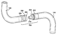
図を次に参照すると、図1は、栄養補給システムで使用される本開示のカップリング100を示している。本開示の残りの部分は、栄養補給システムに関してカップリング100を示しているが、カップリング100は、ラインまたはチューブの接続を解除することが、流体の望ましくない流れを生ずる他のタイプのシステムに組み込むことも可能であることを理解されたい。例えば、医療分野では、カップリング100はまた、静脈内送達によるなど、患者に流体を供給する任意のシステムで有用性を有する。
Referring now to the drawings, FIG. 1 illustrates a
図示のように、栄養補給ソース102および関連する栄養補給ポンプ104は、ソースチューブ108および送り先チューブ110(この例では、チューブ108および110は、総称的に、栄養補給チューブと呼ぶことができる)を介して患者106に接続される。カップリング100は、患者106と栄養補給ソース102の間に位置し、ソースチューブ108および送り先チューブ110を共に接続するために使用される。
As shown, the
カップリング100は、雌アダプタ200および雄アダプタ202を備える。雄アダプタ202は弁500を含み、雌アダプタ200はまた弁502を含む。雌アダプタは、ソースチューブ108の第1の端部に一体に取り付けられる。同様に、雄アダプタ202は、送り先チューブ110の第1の端部に一体に取り付けられる。ソースチューブ108の第2の端部は、ソース102に接続され、送り先チューブ110の第2の端部は、送り先106(例えば、患者)に接続される。図で示されているように、ポンプ104が存在してもよい。ポンプが存在し、かつ図示の構成と同様に接続される場合、ソースチューブ108の第2の端部は、ポンプ104に接続され得る。ソースチューブ108の第2の端部の構成は、カップリング100の動作に影響しないことを理解されたい。
The
雌アダプタ200および雄アダプタ202が結合されたとき、栄養補給ソース102からの内容物は、ソース102およびポンプ104から患者106へと、制御された、一定方向に向かうように流れることができる。すなわち、流体は、雌アダプタおよび雄アダプタが互いに接続されたとき、カップリング100の弁500、502を通って邪魔されずに流れることができる。雌アダプタおよび雄アダプタが相互の接続を解除されたとき、カップリング100の雄アダプタ202内に位置する一方向弁などの弁500が、患者の胃液が、送り先チューブ110の接続されていない端部から外に(患者から外に)逆流するのを阻止する。同様に、雌アダプタ200内の弁502はまた、雄アダプタ202から接続が解除されたとき、動作または活動化される一方向弁となり得る。弁502が、動作または活動化された場合、栄養補給ソースからの流体の流れは、弁502を通ることはできない。その結果、カップリング100における偶発的な接続解除は、大きな混乱を生ずることがなく、あるいは患者の健康もしくは快適さが損なわれることもない。
When the
カップリング100は、栄養補給チューブまたはIVラインに関して使用される場合、患者が治療中または栄養補給中に座る、または横になる間、大きな可動性および移動の容易さを提供する。図2および図3は、結合が解除された状態、または接続が解除された状態のカップリング100の斜視図を示す。ソースチューブ108は、一端で、ソース、または関連するポンプ(図示せず)に接続される。ソースチューブ108は、反対側の端部に、チューブ108の一部として組み込まれた雌アダプタ200を備える。チューブ108の雌アダプタ200の端部は、カップリング100の一部、または半分である。同様に、送り先チューブ110は、一端で、送り先または患者(図示せず)に接続され、また他方の端部で、カップリング100の雄アダプタ202に接続される。雌アダプタおよび雄アダプタ、ならびに各ソースおよび送達チューブの内径および外径は同一である。しかし、いくつかの実施形態では、ソースからの内容物が、結果的に、チューブのいずれかの場所で滞留することがない限り、アダプタの外径は、各チューブの内径に等しいかそれ未満とすることができる、あるいはアダプタの内径が、各チューブの外径と等しいかそれを超えることができる。
Coupling 100, when used with a feeding tube or IV line, provides great mobility and ease of movement while the patient is sitting or lying down during treatment or feeding. 2 and 3 show perspective views of the
雄アダプタ202は、雌アダプタ200の保持リング206に嵌合したとき、雄アダプタ202および雌アダプタ200を共に係合させて、カップリング100を形成するロッキングリング204を備える。ロッキングリング204および保持リング206は、各チューブ110、108に対して遠位の端部付近のその各アダプタ202、200周りの円周に位置している。したがって、アダプタ200、202のカップリングは、ソースチューブ108と送達チューブ110のカップリングとなる。ロッキングリング204および保持リング206は、相補的に共に嵌合する1つまたは複数の溝および隆起部を含むことができる。
The
いくつかの実施形態では、アダプタ200、202を所定量の力で共にスナップ嵌めするだけでロックすることができる。同様に、カップリング100は、雄アダプタ202および雌アダプタ200を、同じまたは同様の力で引っ張って離すことにより、接続を解除することができる。他の実施形態では、カップリングは、挟んで解放する(pinch and release)機構により行うことができる。このような実施形態では、雌アダプタは、さらにロッキングフィンガ208を備えることができる。ロッキングフィンガ208は、雌アダプタ200の周囲の別々の場所に位置することができるが、あるいは単一のロッキングフィンガが、雌アダプタ200の全体の円周方向に位置することもできる。ロッキングフィンガの後部にある開口部は、それらを半径方向内側に押下できるようにする。半径方向内側に押下されたとき、保持リング206は、半径方向外側に開き、それにより、ロッキングリング204を、より容易に挿入できるようにする、または保持リング206から外すことを可能にする。さらに、ロッキングリング204および保持リング206を使用することは、患者、栄養補給ソース、または両方が移動したとき、何らかのカップリング100の接続解除を生ずることなく、またはカップリングを通る流れに多少なりとも影響を与えることなく、ソースおよび送り先チューブ108、110が互いに回転できるようにする。雄アダプタ202および雌アダプタ200は共に、弁500、502を備えるが、それを、以下でより詳細に論ずるものとする。雄アダプタ202は、送り先チューブ110から離れる方向に延びる中空ポスト210をさらに備える。中空ポスト210の先端の開口部212は、ソースからの内容物の流れを可能にする。
In some embodiments, the
図4および図5は、各アダプタに関する弁500、502をより明確に示すために、結合が解除されたカップリング100の横断面を示している。示された例では、雌アダプタ200の弁502は、雌アダプタ200の内部に位置しており、弁502の凹形の側部は、結合が解除されたとき、周囲の空気に開放される。雄アダプタ202の弁500は、中空ポスト210の後部に置かれ、弁500の凹形の側部はまた、ポストの開口部212を介して周囲の空気に開放される。弁500、502は、一方向弁などの圧力弁である。弁はまた、広がって開き、次に閉じたとき折り畳まれる直角なスリットを含むように構成することができるが、あるいはダックビル弁とすることもできる。雌アダプタ200における弁502は、少なくとも30psiの背圧に耐えることができる。したがって、結合が解除されたとき、弁は、ソースまたは関連するポンプからの最高で30psiの流れに耐えることができる。雄アダプタ202の弁500は、少なくとも20psiの背圧に耐えることができ、また0〜1/4psiのクラッキング圧力の範囲で開弁することができる。すなわち、雄アダプタ202の弁500は、結合が解除された状態にあるとき、最高で30psiの患者からの胃腸逆流に耐えることができ、また結合状態にあるときは、ソースまたは関連するポンプからのせいぜい1/4psiの流れで開放されることになる。
4 and 5 show cross-sections of the
要約すると、上記の構成に基づくと、結合が解除された場合、ソースおよび送り先からの内容物の流れは、各チューブ108、110内に滞留する。当然であるが、上記の弁の逆流、およびクラッキング圧力は、限定するように意図されていないことに留意されたい。そうではなくて、弁500、502は、個々の用途に応じて、より大きい、またはより小さい逆流またはクラッキング圧力を有することができる。さらに2つの弁500、502の間の圧力比は、他の実施形態では変わり得ることに留意されたい。弁500、502は、エラストマー、プラスチック、シリコーン、または他の流体流れの制御材料とすることができる。例示的なカップリングで使用できる弁の一タイプは、弁設計に関するいくつかの特許を所有するAptar Group、Inc.の部門である、Midland、MichiganのLMSにより製作されたものである。様々な製造者による他の弁も代替的に使用することができる。
In summary, based on the above configuration, when the bond is released, the flow of contents from the source and destination will reside in each
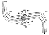
図6および図7を次に参照すると、カップリング100が、接続された状態で示されている。上記で論じたように、雄アダプタ202のロッキングリング204は、接続された状態で、雌アダプタ200の保持リング206内に嵌合する。これは、患者、栄養補給ソース、またはその両方が動いたとき、カップリング100の望ましくない接続解除を生ずることなく、またはこのような動きにより、カップリング100を通るソースからの内容物の流れに悪影響を与えることなく、ソースチューブ108および送り先チューブ110を互いに対して回転できるようにする。
6 and 7, the
図8および図9で示すように、雄アダプタ202および雌アダプタ200が結合されたとき、雄アダプタ202の中空ポスト210は、雌アダプタ200の弁502を貫通し、それにより、雌アダプタ200の弁502を開く。矢印で示されているように、ソースからの内容物の流れは、ソースチューブ108を通り、ポスト210の中へと進むことができ、かつ十分な圧力を用いて、雄アダプタ202の弁500を開き、送り先チューブ110を通って患者へと進む。雄アダプタ202が取り外されたとき、ポスト210がもはや弁502を貫通していないため、雌アダプタ200の弁502は閉じる。したがって、ポスト210を外すことは、ソースチューブ108外に、または雄アダプタ202および送り先チューブ110の中に、内容物がさらに流れることを阻止する。連続して流れることなく、雄アダプタ202の弁500は閉じ、それにより、送り先からの逆流が阻止される。
As shown in FIGS. 8 and 9, when the
本明細書で使用されるいくつかの専門用語は、便宜状使用されるだけであり、本発明を限定するものと解釈されるべきではない。本明細書で使用される相対的な文言は、図面を参照すれば最もよく理解される。図面中、同様の数字は、同様の、または類似の項目を識別するために使用される。さらに図面では、いくつかの機能が、幾分概略的な形で示される可能性がある。 Some terminology used herein is for convenience only and should not be construed as limiting the invention. The relative language used in this specification is best understood with reference to the drawings. In the drawings, like numbers are used to identify similar or similar items. Moreover, in the drawings, some functions may be shown in somewhat schematic form.
特許請求される発明の様々な特徴が上記で提示されているが、特徴は、個々に使用することができるが、あるいはそれらの任意の組合せで使用できることも理解されたい。したがって、特許請求される発明は、本明細書で示された特定の実施形態だけに限定されるものではない。 Although various features of the claimed invention are presented above, it should also be understood that the features can be used individually or in any combination thereof. Therefore, the claimed invention is not limited to only the specific embodiments illustrated herein.
さらに、特許請求される発明が属する分野の当業者であれば、諸変形形態および諸変更形態が想到されるはずであることを理解されたい。本明細書で述べた実施形態は、特許請求される発明を例示するものである。本開示は、特許請求の範囲で記載された本発明の要素に同様に対応する代替的な要素を有する実施形態を当業者が作成し、かつ使用できるようにする。本発明の意図された範囲は、したがって、特許請求の範囲の文言と異ならない、または非実質的に異なっている他の実施形態を含むことができる。したがって、本発明の範囲は、添付の特許請求の範囲で記載されたように定義される。 Furthermore, it should be understood that variations and modifications will occur to those skilled in the art to which the claimed invention belongs. The embodiments described herein are illustrative of the claimed invention. This disclosure enables one skilled in the art to make and use embodiments having alternative elements that likewise correspond to the elements of the invention recited in the claims. The intended scope of the invention may, therefore, include other embodiments that do not differ or are substantially different from the language of the claims. Accordingly, the scope of the invention is defined as set forth in the appended claims.
Claims (11)
ソースチューブの第1の端部に一体的に取り付けられた雌アダプタであって、前記ソースチューブの第2の端部には供給ソースが接続されていて、前記供給ソースから前記ソースチューブの前記第1の端部を通る流体の流れを、雌アダプタの切断状態時に阻止する一方向弁を備える、雌アダプタと、
送り先チューブの第1の端部に取り付けられた雄アダプタであって、前記送り先チューブの第2の端部には送り先が接続されていて、前記送り先チューブから離れる方向に延びる中空ポストと前記中空ポストの後部に配置された一方向弁とを備え、前記送り先から前記送り先チューブの前記第1の端部を通る流体の逆流を雄アダプタの切断状態時に当該一方向弁により阻止する、雄アダプタと
を備え、
前記雄アダプタと雌アダプタとが互いに結合された状態で、前記雄アダプタの前記中空ポストが、前記雌アダプタの一方向弁を貫通して、前記雌アダプタの一方向弁を開き、前記供給ソースからの流れ圧力が、前記雄アダプタの一方向弁を開いて、前記供給ソースから前記ソースチューブおよび前記送り先チューブを通る前記送り先への途切れない流れを容易にし、
前記雌アダプタの一方向弁を貫通した前記中空ポストの端部は、前記中空ポストの後部に位置する一方向弁に対して遠位にあって、前記雄アダプタと前記雌アダプタの両者が結合された状態か結合されていない状態かによらず覆われていない開口を有し、
前記雌アダプタは、一方向弁がある部分の前後に内径を有し、前記雄アダプタは、一方向弁がある部分の前後に内径を有し、
前記雌アダプタの内径は一方向弁がある部分の前後で一定であり、前記雄アダプタの内径は一方向弁がある部分の前後で一定である、チューブカップリング。 A tube coupling,
A female adapter integrally attached to a first end of a source tube, wherein a source is connected to a second end of the source tube, the source source connecting the source to the first end of the source tube. A female adapter comprising a one-way valve for blocking fluid flow through one end of the female adapter when the female adapter is in a disconnected state;
A male adapter attached to a first end of a destination tube, the destination being connected to a second end of the destination tube, the hollow post extending in a direction away from the destination tube, and the hollow post. A one-way valve disposed at a rear portion of the male adapter, the back-flow of fluid from the destination passing through the first end of the destination tube is blocked by the one-way valve when the male adapter is in a disconnected state. Prepare,
With the male adapter and the female adapter coupled to each other, the hollow post of the male adapter penetrates the one-way valve of the female adapter to open the one-way valve of the female adapter, Flow pressure to open the one-way valve of the male adapter to facilitate uninterrupted flow from the supply source through the source tube and the destination tube to the destination,
The end of the hollow post that penetrates the one-way valve of the female adapter is distal to the one-way valve that is located at the rear of the hollow post so that both the male and female adapters are connected. Has an uncovered opening regardless of whether it is open or unbonded,
The female adapter includes an inner diameter before and after the portion where there is a one-way valve, the male adapter has an inner diameter before and after the portion where there is a one-way valve,
The inner diameter of the female adapter is constant before and after the portion where there is a one-way valve, the inner diameter of the male adapter Ru constant der before and after the portion where there is a one-way valve, Chi-menu blanking coupling.
Applications Claiming Priority (3)
| Application Number | Priority Date | Filing Date | Title |
|---|---|---|---|
| US201361914039P | 2013-12-10 | 2013-12-10 | |
| US61/914,039 | 2013-12-10 | ||
| PCT/US2014/067595 WO2015088787A1 (en) | 2013-12-10 | 2014-11-26 | Auto-shutoff coupling |
Related Child Applications (1)
| Application Number | Title | Priority Date | Filing Date |
|---|---|---|---|
| JP2018245084A Division JP7260300B2 (en) | 2013-12-10 | 2018-12-27 | self-shutoff coupling |
Publications (2)
| Publication Number | Publication Date |
|---|---|
| JP2016539715A JP2016539715A (en) | 2016-12-22 |
| JP6703943B2 true JP6703943B2 (en) | 2020-06-03 |
Family
ID=53270102
Family Applications (2)
| Application Number | Title | Priority Date | Filing Date |
|---|---|---|---|
| JP2016537013A Active JP6703943B2 (en) | 2013-12-10 | 2014-11-26 | Automatic shut-off coupling |
| JP2018245084A Active JP7260300B2 (en) | 2013-12-10 | 2018-12-27 | self-shutoff coupling |
Family Applications After (1)
| Application Number | Title | Priority Date | Filing Date |
|---|---|---|---|
| JP2018245084A Active JP7260300B2 (en) | 2013-12-10 | 2018-12-27 | self-shutoff coupling |
Country Status (7)
| Country | Link |
|---|---|
| US (1) | US10315025B2 (en) |
| EP (1) | EP3079756B1 (en) |
| JP (2) | JP6703943B2 (en) |
| AU (1) | AU2014364240B2 (en) |
| BR (1) | BR112016007191B1 (en) |
| CA (1) | CA2925342C (en) |
| WO (1) | WO2015088787A1 (en) |
Families Citing this family (11)
| Publication number | Priority date | Publication date | Assignee | Title |
|---|---|---|---|---|
| CA2925342C (en) * | 2013-12-10 | 2018-09-11 | Applied Medical Technology, Inc. | Auto-shutoff coupling |
| WO2017027329A1 (en) * | 2015-08-07 | 2017-02-16 | Merit Medical Systems, Inc. | Medical break-away connectors |
| WO2017027885A1 (en) | 2015-08-13 | 2017-02-16 | Site Saver, Inc. | Breakaway connector |
| USD851759S1 (en) | 2018-01-17 | 2019-06-18 | Site Saver, Inc. | Breakaway connector for medical lines |
| EP3740273A4 (en) | 2018-01-19 | 2021-10-20 | Site Saver, Inc. | Breakaway medical tubing connector |
| USD905235S1 (en) | 2018-03-30 | 2020-12-15 | Merit Medical Systems, Inc. | Kit of breakaway connectors |
| USD865954S1 (en) | 2018-03-30 | 2019-11-05 | Merit Medical Systems, Inc. | Breakaway connector |
| TWI761220B (en) * | 2021-05-27 | 2022-04-11 | 蘇建忠 | Two-piece nasogastric tube with reduced food reflux |
| US20230072783A1 (en) * | 2021-09-08 | 2023-03-09 | Alexandria Tassopoulos | Medical Tubing Arrangement Comprising a Valve |
| GB2620624A (en) * | 2022-07-14 | 2024-01-17 | The Nottingham Trent Univ | Chest drain connector |
| US20240050728A1 (en) * | 2022-08-11 | 2024-02-15 | Carefusion 303, Inc. | Fluid connector system |
Family Cites Families (42)
| Publication number | Priority date | Publication date | Assignee | Title |
|---|---|---|---|---|
| US3278205A (en) * | 1963-05-16 | 1966-10-11 | Hi Shear Corp | Coupling |
| US5776116A (en) * | 1983-01-24 | 1998-07-07 | Icu Medical, Inc. | Medical connector |
| US4950254A (en) | 1988-10-14 | 1990-08-21 | Corpak, Inc. | Valve means for enteral therapy administration set |
| US4968294A (en) * | 1989-02-09 | 1990-11-06 | Salama Fouad A | Urinary control valve and method of using same |
| US5839614A (en) | 1991-12-06 | 1998-11-24 | Aptar Group, Inc. | Dispensing package |
| US5280876A (en) * | 1993-03-25 | 1994-01-25 | Roger Atkins | Limited restriction quick disconnect valve |
| US5402826A (en) * | 1994-03-07 | 1995-04-04 | Nordson Corporation | Coupling device |
| US5954237A (en) | 1995-08-25 | 1999-09-21 | The Coca-Cola Company | Dispensing valve closure with inner seal |
| US5680969A (en) | 1995-12-18 | 1997-10-28 | Aptargroup, Inc. | Closure with dispensing valve and separate releasable internal shipping seal |
| US5848997A (en) * | 1996-03-15 | 1998-12-15 | Becton Dickinson And Company | Disconnect for medical access devices |
| US5676289A (en) | 1996-04-04 | 1997-10-14 | Aptargroup, Inc. | Valve-controlled dispensing closure with dispersion baffle |
| US5927566A (en) | 1996-07-11 | 1999-07-27 | Aptargroup, Inc. | One-piece dispensing system and method for making same |
| US5797523A (en) | 1997-02-06 | 1998-08-25 | Aptargroup, Inc. | Snap-action closure with disengaged compression member when lid is closed |
| US5934512A (en) | 1997-04-09 | 1999-08-10 | The Coca-Cola Company | Dispensing valve closure with inner seal |
| US5944234A (en) | 1998-01-21 | 1999-08-31 | Aptargroup, Inc. | Dispensing closure for package containing a consumable beverage |
| US6045004A (en) | 1998-03-20 | 2000-04-04 | Aptargroup, Inc. | Dispensing structure with dispensing valve and barrier penetrator |
| US5971232A (en) | 1998-06-03 | 1999-10-26 | Aptargroup, Inc. | Dispensing structure which has a pressure-openable valve retained with folding elements |
| US6006960A (en) | 1998-10-28 | 1999-12-28 | Aptargroup, Inc. | Dispensing structure which has a lid with a pressure-openable valve |
| US5938086A (en) | 1998-11-05 | 1999-08-17 | Aptargroup, Inc. | Container and closure with non-rising rotatable housing, dispensing valve, and separate releasable internal shipping seal |
| US6050451A (en) | 1998-11-19 | 2000-04-18 | Aptargroup, Inc. | Dispensing structure incorporating a valve-containing fitment for mounting to a container and a package with a dispensing structure |
| US6065642A (en) | 1998-12-09 | 2000-05-23 | Aptargroup, Inc. | Non-venting valve and dispensing package for fluid products and the like |
| US6062435A (en) | 1999-05-06 | 2000-05-16 | Aptargroup, Inc. | Valved dispensing system with priming liquid loss prevention |
| US6354564B1 (en) * | 1999-06-09 | 2002-03-12 | Perfecting Coupling Company | Quick-disconnect fluid coupling with check valve |
| US6176399B1 (en) | 1999-07-12 | 2001-01-23 | Aptargroup, Inc | Valved dispensing system for multiple dispensing streams |
| US8377039B2 (en) * | 2002-10-04 | 2013-02-19 | Nxstage Medical, Inc. | Injection site for male luer or other tubular connector |
| US20050015075A1 (en) * | 2003-07-14 | 2005-01-20 | B & D Research And Development Inc. | Coupling device for medical lines |
| AU2004255369B2 (en) | 2003-07-14 | 2010-04-15 | B & D Research And Development Inc. | Coupling device for medical lines |
| US7537024B2 (en) * | 2003-07-29 | 2009-05-26 | Societe Bic | Fuel cartridge with connecting valve |
| CA2591727A1 (en) * | 2004-12-30 | 2006-07-13 | Vasogen Ireland Limited | Controlled flow apparatus for medical accessories |
| US20080197626A1 (en) * | 2005-05-16 | 2008-08-21 | David Coambs | Coupling Device for Medical Lines |
| US7931253B1 (en) * | 2005-09-27 | 2011-04-26 | Checkwater LLC | Quick coupling and uncoupling tube assembly |
| US8657788B2 (en) * | 2006-02-07 | 2014-02-25 | Tecpharma Licensing Ag | Infusion set |
| US20080027415A1 (en) * | 2006-07-28 | 2008-01-31 | Becton, Dickinson And Company | Vascular access device volume displacement |
| US8397956B2 (en) | 2007-03-27 | 2013-03-19 | Aptargroup, Inc. | Dispensing valve with improved dispensing |
| US8142418B2 (en) | 2007-12-19 | 2012-03-27 | Kimberly-Clark Worldwide, Inc. | Automatic shut-off connector for enteral feeding devices |
| US8316890B2 (en) | 2008-11-11 | 2012-11-27 | Aptargroup, Inc. | Port closure system with hydraulic hammer resistance |
| US8454579B2 (en) * | 2009-03-25 | 2013-06-04 | Icu Medical, Inc. | Medical connector with automatic valves and volume regulator |
| CH700975A1 (en) * | 2009-05-08 | 2010-11-15 | Medela Holding Ag | DRAINAGE TUBE DEVICE AND UNIT coupling. |
| US7955317B2 (en) | 2009-06-30 | 2011-06-07 | Tyco Healthcare Group Lp | Female adaptor for feeding line |
| JP5562130B2 (en) * | 2010-06-14 | 2014-07-30 | 日本コヴィディエン株式会社 | Male connector and infusion line connecting device having the same |
| US8974437B2 (en) * | 2011-07-28 | 2015-03-10 | Applied Medical Technology, Inc. | Coupling for medical fluids |
| CA2925342C (en) * | 2013-12-10 | 2018-09-11 | Applied Medical Technology, Inc. | Auto-shutoff coupling |
-
2014
- 2014-11-26 CA CA2925342A patent/CA2925342C/en active Active
- 2014-11-26 WO PCT/US2014/067595 patent/WO2015088787A1/en active Application Filing
- 2014-11-26 JP JP2016537013A patent/JP6703943B2/en active Active
- 2014-11-26 US US14/554,505 patent/US10315025B2/en active Active
- 2014-11-26 BR BR112016007191-3A patent/BR112016007191B1/en active IP Right Grant
- 2014-11-26 AU AU2014364240A patent/AU2014364240B2/en active Active
- 2014-11-26 EP EP14870317.6A patent/EP3079756B1/en active Active
-
2018
- 2018-12-27 JP JP2018245084A patent/JP7260300B2/en active Active
Also Published As
| Publication number | Publication date |
|---|---|
| US20150157849A1 (en) | 2015-06-11 |
| EP3079756A1 (en) | 2016-10-19 |
| EP3079756A4 (en) | 2017-01-11 |
| CA2925342A1 (en) | 2015-06-18 |
| JP2019088804A (en) | 2019-06-13 |
| EP3079756B1 (en) | 2019-03-13 |
| JP7260300B2 (en) | 2023-04-18 |
| AU2014364240B2 (en) | 2017-02-02 |
| WO2015088787A1 (en) | 2015-06-18 |
| US10315025B2 (en) | 2019-06-11 |
| JP2016539715A (en) | 2016-12-22 |
| CA2925342C (en) | 2018-09-11 |
| BR112016007191A2 (en) | 2017-08-01 |
| BR112016007191B1 (en) | 2022-02-22 |
| AU2014364240A1 (en) | 2016-06-09 |
Similar Documents
| Publication | Publication Date | Title |
|---|---|---|
| JP6703943B2 (en) | Automatic shut-off coupling | |
| EP2736584B1 (en) | Coupling for medical fluids | |
| US8142418B2 (en) | Automatic shut-off connector for enteral feeding devices | |
| ES2849048T3 (en) | Luer connector configured to inhibit disconnection | |
| JP2019088804A5 (en) | ||
| AU2015264634B2 (en) | Interlock feed set coupling | |
| JP2017520356A5 (en) | ||
| US9919143B2 (en) | Medical connection device with valve and method | |
| US20240099939A1 (en) | Safety assembly for the reconstitution, the taking and the infusion of pharmacological liquids | |
| TW202208016A (en) | Coupling device, medical tube has the coupling device, and medical kit has the medical tube |
Legal Events
| Date | Code | Title | Description |
|---|---|---|---|
| A621 | Written request for application examination |
Free format text: JAPANESE INTERMEDIATE CODE: A621 Effective date: 20160804 |
|
| A977 | Report on retrieval |
Free format text: JAPANESE INTERMEDIATE CODE: A971007 Effective date: 20170531 |
|
| A131 | Notification of reasons for refusal |
Free format text: JAPANESE INTERMEDIATE CODE: A131 Effective date: 20170606 |
|
| A521 | Request for written amendment filed |
Free format text: JAPANESE INTERMEDIATE CODE: A523 Effective date: 20170817 |
|
| A131 | Notification of reasons for refusal |
Free format text: JAPANESE INTERMEDIATE CODE: A131 Effective date: 20180130 |
|
| A601 | Written request for extension of time |
Free format text: JAPANESE INTERMEDIATE CODE: A601 Effective date: 20180427 |
|
| A521 | Request for written amendment filed |
Free format text: JAPANESE INTERMEDIATE CODE: A523 Effective date: 20180723 |
|
| A02 | Decision of refusal |
Free format text: JAPANESE INTERMEDIATE CODE: A02 Effective date: 20180828 |
|
| A521 | Request for written amendment filed |
Free format text: JAPANESE INTERMEDIATE CODE: A523 Effective date: 20181227 |
|
| C60 | Trial request (containing other claim documents, opposition documents) |
Free format text: JAPANESE INTERMEDIATE CODE: C60 Effective date: 20181227 |
|
| C11 | Written invitation by the commissioner to file amendments |
Free format text: JAPANESE INTERMEDIATE CODE: C11 Effective date: 20190122 |
|
| A911 | Transfer to examiner for re-examination before appeal (zenchi) |
Free format text: JAPANESE INTERMEDIATE CODE: A911 Effective date: 20190307 |
|
| C21 | Notice of transfer of a case for reconsideration by examiners before appeal proceedings |
Free format text: JAPANESE INTERMEDIATE CODE: C21 Effective date: 20190312 |
|
| A912 | Re-examination (zenchi) completed and case transferred to appeal board |
Free format text: JAPANESE INTERMEDIATE CODE: A912 Effective date: 20190426 |
|
| C211 | Notice of termination of reconsideration by examiners before appeal proceedings |
Free format text: JAPANESE INTERMEDIATE CODE: C211 Effective date: 20190514 |
|
| C22 | Notice of designation (change) of administrative judge |
Free format text: JAPANESE INTERMEDIATE CODE: C22 Effective date: 20191119 |
|
| C13 | Notice of reasons for refusal |
Free format text: JAPANESE INTERMEDIATE CODE: C13 Effective date: 20191224 |
|
| A521 | Request for written amendment filed |
Free format text: JAPANESE INTERMEDIATE CODE: A523 Effective date: 20200217 |
|
| C23 | Notice of termination of proceedings |
Free format text: JAPANESE INTERMEDIATE CODE: C23 Effective date: 20200317 |
|
| C03 | Trial/appeal decision taken |
Free format text: JAPANESE INTERMEDIATE CODE: C03 Effective date: 20200414 |
|
| C30A | Notification sent |
Free format text: JAPANESE INTERMEDIATE CODE: C3012 Effective date: 20200414 |
|
| A61 | First payment of annual fees (during grant procedure) |
Free format text: JAPANESE INTERMEDIATE CODE: A61 Effective date: 20200511 |
|
| R150 | Certificate of patent or registration of utility model |
Ref document number: 6703943 Country of ref document: JP Free format text: JAPANESE INTERMEDIATE CODE: R150 |
|
| R250 | Receipt of annual fees |
Free format text: JAPANESE INTERMEDIATE CODE: R250 |