JP6703761B2 - Drive device, transport device, and image forming apparatus - Google Patents
Drive device, transport device, and image forming apparatus Download PDFInfo
- Publication number
- JP6703761B2 JP6703761B2 JP2016087543A JP2016087543A JP6703761B2 JP 6703761 B2 JP6703761 B2 JP 6703761B2 JP 2016087543 A JP2016087543 A JP 2016087543A JP 2016087543 A JP2016087543 A JP 2016087543A JP 6703761 B2 JP6703761 B2 JP 6703761B2
- Authority
- JP
- Japan
- Prior art keywords
- drive
- drive transmission
- swing
- switching
- output
- Prior art date
- Legal status (The legal status is an assumption and is not a legal conclusion. Google has not performed a legal analysis and makes no representation as to the accuracy of the status listed.)
- Active
Links
Images


Description
本発明は、駆動装置、搬送装置および画像形成装置に関するものである。 The present invention relates to a drive device, a transport device, and an image forming apparatus.
従来から、分岐爪などの揺動部材の姿勢を変更して、記録媒体などの搬送物の搬送先を選択的に切り替える搬送装置が知られている。 2. Description of the Related Art Conventionally, there is known a transport device that changes a posture of a swinging member such as a branch claw to selectively switch a transport destination of a transport medium such as a recording medium.
特許文献1には、上記搬送装置として、駆動モータなどの駆動源を正転・逆転させることにより分岐爪などの揺動部材を互いに異なる方向に揺動させる搬送装置が記載されている。また、この搬送装置には、駆動源の駆動を維持した状態で、揺動部材を第一の姿勢または第二の姿勢に保持する揺動保持手段を備えている。
近年、装置の低騒音化が求められてきている。しかしながら、特許文献1においては、揺動部材を一方向へ揺動させ、揺動部材を第一の姿勢から第二の姿勢にした後、再び第一の姿勢に戻すには、一旦、駆動モータを停止させた後、駆動モータを逆回転駆動させる必要がある。従って、第二の姿勢から第一の姿勢へ揺動部材を戻す際に、駆動モータの立ち上げ音が発生し、装置の低騒音化の妨げになっているという課題があった。
In recent years, it has been required to reduce the noise of the device. However, in
上記課題を解決するために、本発明は、駆動源と、揺動可能に設けられた揺動部材が第一の姿勢と第二の姿勢とを選択的に取りうるように、前記揺動部材に前記駆動源の駆動力を伝達する駆動伝達手段と、前記駆動源の駆動を維持した状態で、前記揺動部材を前記第一の姿勢または前記第二の姿勢に保持する揺動保持手段とを備えた駆動装置において、前記駆動源の回転方向を変えずに前記揺動部材の揺動方向を切り替える揺動方向切替手段を備え、前記揺動保持手段は、前記揺動部材を前記第一の姿勢および前記第二の姿勢で止めるストッパ手段と、前記揺動部材への駆動伝達を制限する駆動伝達制限手段とを有し、前記駆動伝達制限手段は、トルクリミッタであることを特徴とするものである。 In order to solve the above-mentioned problems, the present invention provides a swing source so that a swing source provided swingably can selectively take a first posture and a second posture. Drive transmission means for transmitting the driving force of the drive source, and swing holding means for holding the swing member in the first posture or the second posture while maintaining the drive of the drive source. in the driving apparatus having a, with a swinging direction switching means for switching the swinging direction of the swing member without changing the rotational direction of the driving source, the swinging retaining means, the said rocking member first And a drive transmission limiting means for limiting drive transmission to the rocking member, and the drive transmission limiting means is a torque limiter. It is a thing.
本発明によれば、装置の低騒音化を図ることができる。 According to the present invention, it is possible to reduce the noise of the device.
以下、図面を参照して本発明の実施形態について説明する。
図1は、本発明の一実施形態に係る画像形成装置の全体構成を示す概略構成図である。
図1において、画像形成装置としてのレーザプリンタ100は、イエロー(Y),マゼンダ(M),シアン(C),ブラック(K)のトナー像を形成する画像形成手段としての4つの画像形成ユニット1Y,M,C,Kを備えている。また、一次転写手段としての中間転写ユニット10、中間転写ベルト11上のトナー像をシートとしてのシート状の用紙(記録媒体)に転写する二次転写ローラ15から構成される二次転写装置16、用紙に転写されたトナー像を定着する定着装置17を備えている。また、用紙を排出する排紙部18、両面印刷時に第一面を印刷後に両面経路へ用紙を導入する反転部19、排紙部18と反転部19との間で用紙の搬送先を切り替える切替爪23を備えている。さらに、用紙Pを収納する給紙トレイ24、給紙トレイ24からの用紙が搬送される給紙搬送路22、両面印刷時に反転部19からの用紙が搬送される両面搬送路21等を備えている。
Embodiments of the present invention will be described below with reference to the drawings.
FIG. 1 is a schematic configuration diagram showing an overall configuration of an image forming apparatus according to an embodiment of the present invention.
In FIG. 1, a
4つの画像形成ユニット1Y,M,C,Kは、画像形成物質として、互いに異なる色のY,M,C,Kトナー(現像剤)を用いるが、それ以外は同様の構成になっており、寿命到達時に交換される。Kトナー像を形成するための画像形成ユニット1Kを例に説明する。画像形成ユニット1Kは、像担持体としての円筒形状の感光体2、感光体2の表面を帯電する帯電装置、帯電された感光体2の表面を画像情報により露光して感光体2上に静電潜像を形成する露光装置3を備えている。また、感光体2上の静電潜像をKトナーで現像して感光体2上にKトナー像を形成する現像装置4、現像装置4の上方に設置されKトナーを収納する現像剤カートリッジ5、転写後の感光体2の表面をクリーニングするクリーニング装置6等を備えている。 The four image forming units 1Y, M, C, and K use Y, M, C, and K toners (developers) of different colors as image forming substances, but have the same configuration except that. It is replaced when it reaches the end of its life. An image forming unit 1K for forming a K toner image will be described as an example. The image forming unit 1K includes a cylindrical photoconductor 2 as an image carrier, a charging device that charges the surface of the photoconductor 2, and a surface of the charged photoconductor 2 that is exposed by image information to be statically placed on the photoconductor 2. An exposure device 3 for forming a latent image is provided. Further, a developing device 4 for developing the electrostatic latent image on the photoconductor 2 with K toner to form a K toner image on the photoconductor 2, and a developer cartridge 5 installed above the developing device 4 and containing K toner. A cleaning device 6 for cleaning the surface of the photoconductor 2 after transfer is provided.
中間転写ユニット10は、複数の感光体2上の各トナー像を重ねる無端状の中間転写ベルト11を有している。また、中間転写ベルト11を介して感光体2に対向して配置され、この感光体表面に形成されたトナー像を中間転写ベルト11に転写するための一次転写ローラ12等を有している。
The
定着装置17は、ハロゲンランプ等の発熱源を内包する定着ローラ17aと、定着ローラ17aに所定の圧力で当接しながら回転する加圧ローラ17bとが設けられており、定着ローラ17aと加圧ローラ17bとによって定着ニップを形成している。
The
二次転写ローラ15の用紙搬送方向上流側には、レジストローラ対14が設けられている。用紙Pは先端縁が用紙Pの搬送方向と直交するように搬送されるが、先端縁が搬送方向と直交せずに斜めになった状態で搬送される斜行が生じる場合がある。用紙Pの斜行を補正するために、レジストローラ対14に用紙Pの先端を突き当てて、一度用紙Pをたるませてから所定のタイミングで二次転写装置16に用紙を搬送するように制御される。このたるみと用紙P自体のコシとにより、用紙Pの先端縁がレジストローラ対14の回転軸に平行なニップ部に倣って用紙Pの斜行が補正され、中間転写ベルト11上のトナー像の位置を用紙に精度良く合わせて、転写することができる。
A
レーザプリンタ100で画像形成する場合、給紙トレイ24に積載された用紙Pは、給紙ローラ13で給紙され、給紙搬送路22を通り、停止しているレジストローラ対14で一度たるみが形成される。その後、中間転写ベルト11上のトナー像に対して所定のタイミングでレジストローラ対14による用紙Pの搬送が始まり、二次転写装置16、定着装置17、排紙部18を経て排紙トレイ20に排紙される。または、切替爪23で切り替えて反転部19へ用紙Pを搬送し、そこで反転して両面搬送路21を経て再び二次転写位置へと導き、裏面にも画像を記録した後、排紙部18を経て排紙トレイ20に排紙される。
When an image is formed by the
図2は、切替爪23周辺を示す概略構成図である。
本実施形態では、排紙部18は、排紙反転駆動ローラ25と排紙従動ローラ18aとからなる排紙ローラ対を有しており、反転部19は、排紙反転駆動ローラ25と反転従動ローラ19aとからなる反転ローラ対を有している。本実施形態では、排紙ローラ対の駆動ローラと、反転ローラ対の駆動ローラを共通の駆動ローラとしている。
FIG. 2 is a schematic configuration diagram showing the periphery of the
In the present embodiment, the
揺動部材たる切替爪23は、排紙反転駆動ローラ25の用紙搬送方向上流側に隣接し、反転部19の用紙搬送経路と、排紙部18の用紙搬送経路との間に配置されている。切替爪23の用紙搬送方向下流側端部には、揺動軸23aが設けられており、切替爪23は、この揺動軸23aを支点にして揺動自在に支持されている。切替爪23は、図中実線に示す第一の姿勢と、図中点線で示す第二の姿勢とを取るように揺動する。
The switching
用紙を、排紙トレイ20へ排出するときは、切替爪23を図中実線で示す第一の姿勢にし、排紙反転駆動ローラ25を図中時計回りに回転駆動する。これにより、定着装置17を通過した用紙Pは、切替爪23により排紙部18へ案内され、排紙反転駆動ローラ25と排紙従動ローラ18aとからなる排紙ローラ対により、排紙トレイ20へ排出される。
When the paper is discharged to the
図3は、用紙Pを両面搬送路21へ搬送するときの切替爪23および排紙反転駆動ローラ25の動作について説明する図である。
図3(a)に示すように画像形成動作がスタートすると、切替爪23を図中点線で示す第一の姿勢から図中実線で示す第二の姿勢となるように揺動させる。また、排紙反転駆動ローラ25を図中反時計回りに回動させる。これにより、定着装置17を通過した用紙Pは、切替爪23により反転部19へ案内され、排紙反転駆動ローラ25と反転従動ローラ19aとからなる反転ローラ対により搬送される。
FIG. 3 is a diagram for explaining the operation of the switching
When the image forming operation is started as shown in FIG. 3A, the switching
図3(b)に示すように、用紙Pの後端Ptが排紙部18と反転部19との分岐部を通過して、図3(b)の位置に到達したら、排紙反転駆動ローラ25を図中時計回りに回転させて、用紙をスイッチバックして、両面搬送路21へ搬送する。また、切替爪23が第二の姿勢から第一の姿勢となるように、切替爪23を揺動させる。これにより、用紙Pが両面搬送路21へ搬送され、用紙の第二面に画像を形成された後、切替爪23により排紙部18へ搬送され、排紙ローラ対により排紙トレイ20へ排紙される。
As shown in FIG. 3B, when the trailing edge Pt of the paper P passes through the branch portion between the
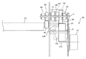
図4は、切替爪23を駆動する駆動装置30を示す概略断面図である。
駆動装置30は、揺動部材であり、搬送先案内部材である切替爪23を駆動する駆動源たるモータ31を備えており、モータ31は、ブラケット41に取り付けられている。モータ31のモータ軸は、ブラケット41を貫通しており、モータ軸の外周には歯が形成されておりモータギヤ31aとなっている。
FIG. 4 is a schematic cross-sectional view showing the
The
切替爪23への駆動伝達経路として、駆動出力部材たる出力軸tを互いに異なる方向に回転させる二系統の駆動伝達経路を備えている。二系統の駆動伝達経路の一方である第一駆動伝達経路R1は、第一入力プーリ35、第一出力プーリ36及びこれらに張架された第一タイミングベルト38で構成されたベルト駆動伝達経路となっている。一方、二系統の駆動伝達経路の他方である第二駆動伝達経路R2は、第二入力ギヤ32と第二出力ギヤ34とで構成されたギヤ駆動伝達経路となっている。第一駆動伝達経路R1には、第一電磁クラッチ37が設けられており、第二駆動伝達経路R2には、第二トルクリミッタ33が設けられている。
As a drive transmission path to the switching
第一駆動伝達経路R1の第一入力プーリ35と第二駆動伝達経路R2の第二入力ギヤ32とは、一体成型物であり、この一体成型物が、ブラケット41と側板42により固定支持された固定軸sに回転自在に支持されている。第二入力ギヤ32には、モータギヤ31aと、第二駆動伝達経路R2の第二出力ギヤ34とが噛み合っている。
The
出力軸tは、ブラケット41と、側板42とに軸受41a,42aを介して回転自在に支持されており、この出力軸tに第二出力ギヤ34と、第一出力プーリ36とが回転自在に支持されている。また、この出力軸tには、第一電磁クラッチ37が第一出力プーリ36と隣接して取り付けられている。第一電磁クラッチ37の第一出力プーリ36と対向する対向面には、連結爪37aが設けられており、この連結爪37a(図6参照)が、第一出力プーリ36の連結穴36aと係合している。また、この出力軸tには、第二トルクリミッタ33が、第二出力ギヤ34と隣接して取り付けられている。第二トルクリミッタ33は、出力軸tを貫通する取り付けピンu1と係合し、出力軸tと一体で回転するように固定されている。第二トルクリミッタ33の連結爪33aは、第二出力ギヤ34の連結穴34aと係合している。
The output shaft t is rotatably supported by the
出力軸tは、側板42を貫通しており、出力軸tの切替爪23側端部には、切替爪23の揺動軸23aに固定された揺動ギヤ43と噛み合う出力ギヤ39が、回転自在に支持されている。また、この出力軸tには、出力トルクリミッタ40が出力軸tを貫通する取り付けピンu2と係合し、出力軸tと一体で回転するように固定されている。この出力トルクリミッタ40の連結爪40aは、出力ギヤ39と係合している。
The output shaft t penetrates the
上記第二トルクリミッタ33の設定トルクは、上記出力トルクリミッタ40の設定トルクよりも大きく、上記第一電磁クラッチ37から出力軸tへの駆動伝達トルクよりも低く設定されている。
The set torque of the
図5は、図4のX方向から見た概略構成図である。
図5に示すように、切替爪23が第一の姿勢をとったときに、切替爪23が突き当たる第一突き当て部材44aと、切替爪23が第二の姿勢をとったときに、切替爪23が突き当たる第二突き当て部材44bとを有している。すなわち、本実施形態では、第一突き当て部材44aと第二突き当て部材44bとで、切替爪23を第一の姿勢または第二の姿勢で止めるストッパ手段を構成している。
FIG. 5 is a schematic configuration diagram viewed from the X direction in FIG.
As shown in FIG. 5, when the switching
図6は、第一電磁クラッチ37の概略構成図である。
第一電磁クラッチ37は、軸固定部37e、電磁コイル部37d、ロータ部37c、アーマチュア37b、駆動連結部材37fなどを備えている。軸固定部37eには、出力軸tが挿入される挿入穴を有しており、その挿入穴が、断面D字形状となっている。出力軸tには、このD字形状に嵌合するように、切り欠いて、断面D字部分を有している。出力軸tの断面D字部分は、第一電磁クラッチ37が取り付けられた箇所まで延びている。軸固定部37eの断面D字形状部分を、出力軸tの断面D字部分と嵌合させることにより、軸固定部37eを、出力軸tと連れ回りするように固定している。
FIG. 6 is a schematic configuration diagram of the first
The first
軸固定部37eには、電磁コイル部37dが、軸固定部37eに対して回転自在に取り付けられている。一方、ロータ部37cは、軸固定部37eと一体で回転するよう軸固定部37eに固定されている。アーマチュア37bは、第一出力プーリ側に延びる一対の連結爪37aを備えた駆動連結部材37fに取り付けられている。被駆動連結部材たる第一出力プーリ36の第一電磁クラッチ37との対向面には、一対の連結穴36aが形成されており、これら連結穴36aに駆動連結部材37fの連結爪37aが嵌合している。これにより、第一電磁クラッチ37と第一出力プーリ36とが、一体で回転可能となっている。
An electromagnetic coil portion 37d is rotatably attached to the shaft fixing portion 37e with respect to the shaft fixing portion 37e. On the other hand, the
第一電磁クラッチ37のOFF時は、駆動連結部材37fはフリーな状態となっており、軸固定部37eに対して空回り可能な状態となっている。これにより、第一出力プーリ36から出力軸tへの駆動伝達が遮断され、駆動連結部材37fと第一出力プーリ36とが出力軸tに対して空回りする。
When the first
クラッチON時は、電磁コイル部37dに電流が流れ、電磁力が発生する。電磁力が発生すると、金属円盤のアーマチュア37bが、電磁力により、電磁コイル部37dへ引き寄せられ、アーマチュア37bと一体の駆動連結部材37fが、ロータ部37c側へスライド移動する。そして、アーマチュア37bがロータ部37cに吸着し、第一出力プーリ36に伝達された駆動力が第一電磁クラッチ37を介して出力軸tに伝達され、出力軸tが回転する。
When the clutch is ON, a current flows through the electromagnetic coil portion 37d and an electromagnetic force is generated. When the electromagnetic force is generated, the armature 37b made of a metal disk is attracted to the electromagnetic coil portion 37d by the electromagnetic force, and the drive connecting member 37f integrated with the armature 37b slides to the
本実施形態の第一電磁クラッチ37では、駆動連結部材37fを軸方向にスライド移動可能に設ければよく、被駆動連結部材たる第一出力プーリ36は、出力軸tに対して回転可能にすればよい。よって、第一出力プーリ36を軸方向にスライド移動可能に構成する場合に比べて出力軸tとの隙間を小さくでき、第一出力プーリ36が出力軸tに対して傾くのを抑制することができる。
In the first
先の図4に示すように、第一電磁クラッチ37をONにすると、第一駆動伝達経路R1から出力軸tへ駆動力が伝達される。上述したように、第二トルクリミッタ33の設定トルクは、第一電磁クラッチ37の出力軸tへの駆動伝達トルクよりも低いため、第二駆動伝達経路R2から出力軸tへの駆動伝達が遮断され、第二出力ギヤ34が空転する。よって、出力軸tは、第一駆動伝達経路R1からの駆動伝達によりモータギヤ31aの回転方向とは逆方向に回転駆動し、切替爪23が一方向に揺動する。一方、第一電磁クラッチ37をOFFにすると、出力軸tは、第二トルクリミッタ33を介して第二出力ギヤ34から駆動力が伝達され、出力軸tは、モータギヤ31aと同方向、すなわち、第一駆動経路を介して駆動伝達したときとは、逆方向に回転駆動する。これにより、切替爪23の揺動方向が切り替わり、一方向とは逆方向に揺動する。このように、本実施形態では、第一駆動伝達経路R1と、第二駆動伝達経路R2と、第一電磁クラッチ及び第二トルクリミッタで構成された経路切り替え手段とで、駆動源たるモータ31の回転方向を変えずに揺動部材たる切替爪23の揺動方向を切り替える揺動方向切替手段を構成している。
As shown in FIG. 4, when the first
例えば、モータ31が、モータギヤ31a側から見て時計回り(CW)に回転する場合、第一電磁クラッチ37をONにすると、出力軸tが反時計回り(CCW)に回転し、揺動軸23aが時計回りに揺動する。すると、先の図5からわかるように、切替爪23が図中時計回りに揺動する。そして、切替爪23が第二の姿勢となると、第二突き当て部材44bに突き当たり、揺動が規制される。切替爪23が第二突き当て部材44bに突き当たると、トルクが出力トルクリミッタ40の設定トルク以上となり、出力ギヤ39が出力軸tに対して相対的に空回りし、切替爪23が第二の姿勢を保持する。これにより、駆動モータ31の駆動が維持された状態で、切替爪23を第二の姿勢に保持することができる。
For example, when the
切替爪23を第二の姿勢から第一の姿勢にするときは、第一電磁クラッチ37をOFFにし、駆動伝達経路を、第一駆動伝達経路R1から第二駆動伝達経路R2へ切り替える。駆動伝達経路が、第二駆動伝達経路R2に切り替わると、出力軸tが時計回り(CW)に回転し、揺動軸23aが反時計回り(CCW)に回動し、切替爪23が反時計回り(CCW)に揺動する。そして、先の図5に示す第一の姿勢になると、切替爪23が、第一突き当て部材44aに突き当たり、揺動が規制される。上述したように出力トルクリミッタ40の設定トルクは、第二トルクリミッタ33の設定トルクよりも低いため、出力軸tのトルクが、第二トルクリミッタ33の設定トルクに到達する前に、出力トルクリミッタ40が出力ギヤ39への駆動伝達を遮断する。その結果、出力ギヤ39が出力軸tに対して相対的に空回りし、切替爪23が第一の姿勢を保持する。これにより、駆動モータ31の駆動が維持された状態で、切替爪23を第一の姿勢に保持することができる。
When changing the switching
このように、本実施形態では、第一突き当て部材44aおよび第二突き当て部材で構成されたストッパ手段と、駆動制限手段たる出力トルクリミッタとで、駆動源たる駆動モータ31の駆動を維持した状態で、揺動部材たる切替爪23を第一の姿勢または第二の姿勢に保持する揺動保持手段を構成している。
As described above, in the present embodiment, the driving of the
このように、本実施形態では、駆動モータの駆動を維持した状態で、切替爪23を第一の姿勢または第二の姿勢に保持でき、駆動伝達経路を切り替えることで、モータの回転方向を切り替えることなく切替爪23を互いに異なる方向に揺動させることができる。その結果、モータ31を一方向に回転させ続けて、切替爪23を互いに異なる方向に揺動させることができる。よって、モータを正転/逆転させて、切替爪23の揺動方向を切り替える駆動装置とは異なり、切替爪23の揺動方向を切り替えるときに、モータを停止する必要がない。その結果、切替爪23の揺動方向を切り替えるときにモータの立ち上がり音が発生することがなく、装置の静音化を図ることができる。
As described above, in the present embodiment, the switching
また、本実施形態では第二駆動伝達経路R2にトルクリミッタを設け、第一駆動伝達経路R1に電磁クラッチを設けて、駆動伝達経路の切り替えを行っている。これにより、両方の駆動伝達経路にそれぞれ電磁クラッチを設けて、駆動伝達経路を切り替えるものに比べて、以下の利点がある。すなわち、第二駆動伝達経路から出力軸tに駆動力を伝達するときに電力を消費することがない。これにより、第二駆動伝達経路R2にも電磁クラッチを設ける場合に比べて、消費電力を低減することができる。 Further, in the present embodiment, a torque limiter is provided on the second drive transmission path R2, and an electromagnetic clutch is provided on the first drive transmission path R1 to switch the drive transmission path. As a result, there are the following advantages as compared with the case where the electromagnetic clutches are provided on both drive transmission paths and the drive transmission paths are switched. That is, electric power is not consumed when the driving force is transmitted from the second drive transmission path to the output shaft t. As a result, the power consumption can be reduced as compared with the case where the electromagnetic clutch is also provided in the second drive transmission path R2.
また、各駆動伝達経路に電磁クラッチを設けた場合、一方の駆動伝達経路の電磁クラッチをONからOFFに切り替えた後、一方の駆動伝達経路の電磁クラッチをOFFからONに切り替えることで、駆動伝達経路を切り替えることになる。一方、本実施形態では、一方をトルクリミッタとすることで、他方の駆動伝達経路の電磁クラッチをOFFにすれば、一方の駆動伝達経路に切り替わり、電磁クラッチをONにすれば、他方の駆動伝達経路に切り替わる。よって、各駆動伝達経路に電磁クラッチを設けて駆動伝達経路の切り替えを行う場合に比べて、駆動切り替え時間を短縮化できるというメリットもある。 When an electromagnetic clutch is provided in each drive transmission path, the drive transmission is performed by switching the electromagnetic clutch of one drive transmission path from ON to OFF and then switching the electromagnetic clutch of one drive transmission path from OFF to ON. The route will be switched. On the other hand, in the present embodiment, by using one as a torque limiter, if the electromagnetic clutch of the other drive transmission path is turned off, the drive transmission path is switched to one drive transmission path, and if the electromagnetic clutch is turned on, the other drive transmission path is transmitted. Switch to the route. Therefore, there is also an advantage that the drive switching time can be shortened as compared with the case where an electromagnetic clutch is provided in each drive transmission path to switch the drive transmission path.
また、本実施形態では、第一電磁クラッチ37と第二トルクリミッタ33とを同軸に設けている。電磁クラッチを設ける軸およびトルクリミッタを設ける軸は、軸受を介して回転自在に支持された回転軸にする必要がある。そのため、電磁クラッチを設ける軸と、トルクリミッタを設ける軸を、互いに異なる軸に設けた場合は、2本の軸を回転軸とする必要がある。一方、本実施形態のように、第一電磁クラッチ37と第二トルクリミッタ33とを同軸に設けることで、回転軸を1本にすることができ、2本を回転軸にする場合に比べて、軸受などを削減することができ、装置のコストダウンを図ることができる。
Further, in the present embodiment, the first
また、第一駆動伝達経路R1にトルクリミッタを設けて、第二駆動伝達経路R2に電磁クラッチを設けてもよい。 Further, a torque limiter may be provided in the first drive transmission path R1 and an electromagnetic clutch may be provided in the second drive transmission path R2.
上述では、出力ギヤ39の直径と、揺動ギヤ43の直径とを同径として、歯数を同じにしており、切替爪23が、出力軸tと同じ回転数で駆動するようにしているが、図7に示すように、揺動ギヤ43の直径を小さくし、揺動ギヤ43の歯数を、出力ギヤの歯数よりも少なくして、増速してもよい。増速することにより、すばやく搬送経路を切り替えることができ、高速搬送が可能となる。また、切替爪23の配置の自由度を高めることができ、装置のレイアウトの自由度を高めることができる。
In the above description, the diameter of the
また、図8に示すように、揺動ギヤ43の直径を大きくし、揺動ギヤ43の歯数を、出力ギヤの歯数よりも多くして、減速してもよい。減速することにより、切替爪23が、突き当て部材にゆっくり突き当たり、切替爪23が、突き当て部材に突き当たったときの衝撃音を低減することができる。これにより、装置の低騒音化を図ることができる。
Further, as shown in FIG. 8, the diameter of the
また、図9に示すように、第一駆動伝達経路R1を、第一入力ギヤ135と、第一アイドラギヤ138と、第一出力ギヤ136の奇数のギヤ列で構成してもよい。これにより、奇数のギヤ列からなる第一駆動伝達経路R1から駆動力を伝達されたときと、第二入力ギヤ32と第二出力ギヤ34の偶数のギヤ列からなる第二駆動伝達経路R2から駆動力を伝達されたときとで、出力軸tの回転方向を異ならせることができる。従って、かかる構成としても、モータ31の回転方向を切り替えることなく、切替爪23を互いに異なる方向に揺動させることができる。
Further, as shown in FIG. 9, the first drive transmission path R1 may be configured by an odd number gear train of the
次に、駆動装置30の変形例について説明する。
Next, a modified example of the
[変形例1]
図10は、変形例1の駆動装置30Aの概略断面図である。
図10に示すように、この変形例1の駆動装置30Aは、揺動部材である切替爪23と、正転および逆回転する正逆出力対象回転体たる排紙反転駆動ローラ25と、一方向のみ回転する一方向出力対象回転体たる定着ローラ17aとを駆動するものである。
[Modification 1]
FIG. 10 is a schematic cross-sectional view of
As shown in FIG. 10, the
図10に示すように、モータギヤ31aには、上述した第二入力ギヤ32の他に、定着ローラ17aの軸171に取り付けられた定着ギヤ52が噛み合っている。また、排紙反転駆動ローラ25の軸25aに、第一駆動伝達経路R1の第一出力プーリ36と、第二駆動伝達経路R2の第二出力ギヤ34と第一電磁クラッチ37が設けられている。また、第二駆動伝達経路R2には、第二トルクリミッタに替えて、第二電磁クラッチ51を設け、第二電磁クラッチ51は、第一電磁クラッチ37が取り付けられた排紙反転駆動ローラ25の軸25aに取り付けられている。第二電磁クラッチ51は、第一電磁クラッチ37と同様の構成であり、第二電磁クラッチ51の連結爪が、第二出力ギヤ34に係合している。
As shown in FIG. 10, in addition to the
このように、第一電磁クラッチ37と第二電磁クラッチ51とを、同軸に設けることで、以下の利点を得ることができる。すなわち、一般的に、電磁クラッチは、ギヤやプーリなどの駆動伝達部材に比べて寿命が短く、定期的に交換が必要となってくる。電磁クラッチを交換するときは、電磁クラッチが取り付けられた軸にアクセスし、その軸から寿命の電磁クラッチを取り外して、新品の電磁クラッチを軸に取り付ける作業となる。第一電磁クラッチ37と第二電磁クラッチ51とを互いに異なる軸に設けた場合は、それぞれの軸に作業者がアクセスできるようにする必要があり、そのためのスペースを画像形成装置に設ける必要がある。その結果、プリンタの大型化につながる。一方、この変形例1のように、第一電磁クラッチ37と第二電磁クラッチ51とを同軸に設けることで、第一電磁クラッチ37と第二電磁クラッチ51とが設けられた軸(排紙反転駆動ローラ25の軸25a)に作業者がアクセスできるようにすればよい。よって、互いに異なる軸に電磁クラッチを取り付けた構成に比べて、プリンタの小型化を図ることができる。
As described above, by providing the first
切替爪23に駆動力を伝達するための駆動伝達機構を構成する出力ギヤ39と、出力トルクリミッタ40と、揺動ギヤ43は、排紙反転駆動ローラ25の軸25aのモータ側とは反対側の端部付近に設けている。具体的には、定着ローラ17aの軸171のモータ側とは反対側の端部と、排紙反転駆動ローラ25の軸25aのモータ側とは反対側の端部とを軸受55a,55bを介して回転自在に支持する他端側の側板55よりも外側に、出力ギヤ39と、出力トルクリミッタ40と、揺動ギヤ43とが配置されている。
The
このように、出力ギヤ39、出力トルクリミッタ40および揺動ギヤ43からなる切替爪23に駆動力を伝達するための駆動伝達機構を、装置内の第一駆動伝達経路R1や第二駆動伝達経路R2が配設された側と反対側に設けることで、切替爪23に駆動力を伝達するための駆動伝達機構を、上記反対側の空きスペースに配置することが可能となる。その結果、モータ側に切替爪23に駆動力を伝達するための駆動伝達機構も配置する場合に比べて、装置の小型化を図ることができる。
As described above, the drive transmission mechanism for transmitting the drive force to the switching
図11(a)は、用紙Pを排紙部18へ搬送するときの排紙反転駆動ローラ25、切替爪23および定着ローラ17aの回転について説明する図であり、図11(b)は、用紙Pを反転部19へ搬送するときの排紙反転駆動ローラ25、切替爪23および定着ローラ17aの回転について説明する図である。
11A is a diagram for explaining the rotation of the paper ejection reversing
画像形成動作が開始されると、モータ31をモータギヤ31a側見て時計回り(CW)に回転させる。すると、図10に示すように、モータギヤ31aから定着ギヤ52に駆動力が伝達され、定着ローラ17aが、図11に示すように、図中反時計回り(CCW)に回動する。
When the image forming operation is started, the
用紙Pを排紙部18へ搬送するときは、第二電磁クラッチ51をONにし、第一電磁クラッチ37をOFFにする。すると、第二駆動伝達経路R2を介して排紙反転駆動ローラ25の軸25aに駆動力が出力され、排紙反転駆動ローラ25が図11(a)に示すように、図中時計回りに回動する。また、切替爪23は、図中反時計回り(CCW)に揺動し、第一突き当て部材44aに突き当たり、第一の姿勢となる。第一の姿勢となったら、上述したように、出力トルクリミッタ40の働きで切替爪23への駆動伝達が制限され、切替爪23が第一の姿勢で保持ざれる。一方、排紙反転駆動ローラ25には、第二駆動伝達経路R2を介してモータ31の駆動が入力され、排紙反転駆動ローラ25は、図中反時計回りに回動し続ける。これにより、定着ローラ17aにより搬送されてきた用紙Pは、切替爪23により排紙部18へ搬送され、排紙反転駆動ローラ25と排紙従動ローラ18aとからなる排紙ローラ対により排紙トレイ20(図1参照)へ排出される。
When the paper P is conveyed to the
一方、用紙Pを反転部19へ搬送するときは、第二電磁クラッチ51をOFFにし、第一電磁クラッチ37をONにする。すると、第一駆動伝達経路R1を介して排紙反転駆動ローラ25の軸25aに駆動力が出力され、排紙反転駆動ローラ25が図11(b)に示すように、図中反時計回り(CCW)に回動する。また、切替爪23は、図中時計回り(CW)に揺動し、第二突き当て部材44bに突き当たり、第二の姿勢となる。第二の姿勢となったら、上述したように、出力トルクリミッタ40の働きで切替爪23への駆動伝達が制限され、切替爪23が第二の姿勢を保持する。一方、排紙反転駆動ローラ25には、第一駆動伝達経路R1を介してモータ31の駆動が入力され、排紙反転駆動ローラ25は、図中反時計回りに回動し続ける。これにより、定着ローラ17aにより搬送されてきた用紙Pは、切替爪23により反転部19へ搬送され、排紙反転駆動ローラ25と反転従動ローラ19aとからなる反転ローラ対により搬送される。
On the other hand, when the sheet P is conveyed to the reversing
用紙Pの後端が、排紙部18と反転部19との分岐を通過したら、第一電磁クラッチ37をOFFにし、第二電磁クラッチ51をONにする。すると、排紙反転駆動ローラ25が、図11(a)に示すように、図中時計回り(CW)に回転し、排紙反転駆動ローラ25と反転従動ローラ19aとからなる反転ローラ対により用紙Pをスイッチバック搬送する。また、切替爪23が、図中反時計回り(CCW)に揺動し、第一の姿勢となる。これにより、用紙Pが、切替爪23により両面搬送路21(図1参照)へと案内され、用紙Pが両面搬送路21へと搬送される。
When the trailing edge of the paper P passes through the branch between the
この変形例1では、モータ31で定着ローラ17a、排紙反転駆動ローラ25および切替爪23を駆動している。これにより、定着ローラ17a、排紙反転駆動ローラ25および切替爪23をそれぞれ別のモータで駆動する場合に比べて、モータ数を削減することができ、装置のコストダウンを図ることができる。
In the first modification, the
特に、モータ31を一方向に回転させたまま、排紙反転駆動ローラ25の回動方向や切替爪23の揺動方向を切り替えることができるため、定着ローラ17aを停止させることなく、一方向(CCW方向)に回転させ続けることができる。また、反転部19でスイッチバックして用紙Pを両面搬送路21へ搬送するときの排紙反転駆動ローラ25の回転方向と、排紙部18で用紙を排紙トレイ20へ搬送するときの排紙反転駆動ローラ25の回転方向は、同じ方向である。さらに、反転部19でスイッチバックして用紙Pを両面搬送路21へ搬送するとき、用紙Pを排紙部18へ搬送するときいずれも切替爪23は、第一の姿勢をとっている。よって、反転部19でスイッチバックして用紙Pを両面搬送路21へ搬送中に定着ローラ17aによって、用紙Pを排紙部18へ搬送し、排紙反転駆動ローラ25と排紙従動ローラ18aとからなる排紙ローラ対により排紙トレイ20へ搬送することができる。これにより、両面の画像が形成された用紙Pを、片面に画像が記録された用紙Pを両面搬送路21へ搬送中に、排紙部18へ搬送して、排紙トレイ20へ排出することができ、両面プリントの生産性を高めることができる。
In particular, the rotation direction of the paper discharge reversing
また、ギヤ列で構成された第二駆動伝達経路R2の方が、ベルト駆動伝達の第一駆動伝達経路R1よりも耐久性が高い。従って、使用頻度の高い駆動伝達経路を、第二駆動伝達経路R2とするのが好ましい。本実施形態では、用紙Pを排紙部18へ搬送するときの反転駆動ローラ25の回転方向(図11の時計回り方向)が使用頻度高い。従って、反転駆動ローラ25を図11の時計回り方向(CW方向)に回転させる第二駆動伝達経路を、ギヤ列で構成するのが好ましい。
Further, the second drive transmission path R2 configured by the gear train has higher durability than the first drive transmission path R1 for belt drive transmission. Therefore, it is preferable that the drive transmission path that is frequently used is the second drive transmission path R2. In the present embodiment, the rotation direction of the reversal drive roller 25 (the clockwise direction in FIG. 11) when the paper P is conveyed to the
[変形例2]
図12は、変形例2の駆動装置30Bを示す概略断面図である。
この変形例2の駆動装置30Bは、モータギヤ31aに噛み合う内歯と外歯とを備えた駆動アイドラギヤ61を有している。駆動アイドラギヤ61は、ブラケット41と側板42とに固定された固定軸sに回転自在に支持されている。モータギヤ31aは、駆動アイドラギヤ61の内歯に噛み合っている。
[Modification 2]
FIG. 12 is a schematic cross-sectional view showing a
The
モータギヤ31aを駆動アイドラギヤ61の内歯に噛み合せることで、モータギヤ31aとの噛み合い率を高めることができ、回転ムラや騒音・振動の発生を抑制することができる。また、モータギヤ31aとの噛み合い部を駆動アイドラギヤ61で覆うことができ、噛み合い騒音を駆動アイドラギヤ61により遮蔽することができ、装置の静音化を図ることができる。
By engaging the
また、最初の噛み合いであるモータギヤ31aとの噛み合いが騒音の付与率が最も高い。この変形例2では、この騒音の付与率が高いモータギヤ31aとの噛み合いを駆動アイドラギヤ61の内歯との噛み合いのみとすることで、変形例1のように、モータギヤ31aに2個のギヤが噛み合う構成に比べて、騒音を効果的に抑制することができる。
Further, the first engagement, which is the engagement with the
駆動アイドラギヤ61には、駆動出力ギヤ62が噛み合っている。この駆動出力ギヤ62は、ブラケット41、側板42に軸受41b、42cを介して回転自在に支持された回転軸Xに、一体的に回転するように取り付けられている。この回転軸Xのローラ側端部には、定着出力ギヤ63が回転軸Xと一体的に回転するように取り付けられており、定着出力ギヤ63は、定着ローラ17aの軸171に取り付けられた定着ギヤ52と噛み合っている。
A
第二駆動伝達経路R2は二段となっており、一段目は、第二入力プーリ131と、第二出力プーリ133と、こられプーリに張架された第二タイミングベルト132とで構成されたベルト駆動伝達となっている。二段目は、第二入力ギヤ32と第二出力ギヤ34とからなるギヤ列となっている。第二入力プーリ131は、駆動出力ギヤ62と一体で構成されている。第二出力プーリ133は、第二入力ギヤ32と一体で構成されており、この一体物がブラケット41と側板42とに固定された第二固定軸Wに回転自在に支持されている。第二入力ギヤ32と噛み合う第二出力ギヤ34は、排紙反転駆動ローラ25の軸25aに回転自在に支持されている。第二電磁クラッチ51は、排紙反転駆動ローラ25の軸25aに取り付けられており、第二出力ギヤ34と軸方向から係合している。
The second drive transmission path R2 has two stages, and the first stage is composed of a
一方、第一駆動伝達経路R1は、変形例1と同様、第一入力プーリ35と、第一出力プーリ36と、これらに張架された第一タイミングベルト38とで構成されたベルト伝達となっている。第一入力プーリ35は回転軸Xに回転自在に支持されており、第一出力プーリ36は、排紙反転駆動ローラ25の軸25aと一体で回転するように、この軸25aに取り付けられている。第一電磁クラッチ37は、回転軸Xに取り付けられており、第一入力プーリ35に軸方向から係合している。
On the other hand, the first drive transmission path R1 is a belt transmission including the
この変形例2では、第一駆動伝達経路R1および第二駆動伝達経路R2に複数のプーリに張架されたベルト部材を有するベルト駆動伝達部を備えている。これにより、レイアウトの関係上、排紙反転駆動ローラ25が、モータ31よりも離れた箇所に位置していても、必要最小限の駆動伝達部材で、排紙反転駆動ローラ25にモータ31の駆動力を伝達することができる。これにより、第一、第二駆動伝達経路R2をギヤ列のみで構成した場合に比べて、部品点数を削減することができる。
In the second modification, the first drive transmission path R1 and the second drive transmission path R2 are provided with a belt drive transmission section having a belt member stretched around a plurality of pulleys. Accordingly, due to the layout, even if the paper ejection
また、この変形例2では、第一電磁クラッチ37を回転軸Xに設け、第二電磁クラッチ51を排紙反転駆動ローラ25の軸25aに設けており、第一電磁クラッチ37と第二電磁クラッチ51とを互いに異なる軸に設けている。電磁クラッチは、ギヤやプーリに比べて軸方向に長いため、第一電磁クラッチ37と第二電磁クラッチ51とを同軸上に設けた場合は、装置が軸方向に大型化するおそれがある。従って、この変形例2のように、第一電磁クラッチ37と第二電磁クラッチ51とを互いに異なる軸に設けることで、装置が軸方向に大型化するのを抑制することができる。
In the second modification, the first
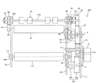
図13は、変形例2の駆動装置30Bにおける、切替爪23に駆動力を伝達するための駆動伝達機構の概略図である。
図13に示すように変形例2においては、切替爪23に駆動力を伝達するための駆動伝達機構が、切替入力プーリ139と、切替出力プーリ143と、これらプーリに張架された切替タイミングベルト142とで構成し、ベルト駆動伝達としている。切替入力プーリ139は、排紙反転駆動ローラ25の軸25aのモータ側とは反対側の端部に、この軸25aと一体的に回転するように取り付けられている。切替出力プーリ143は、揺動軸23aに回転自在に支持されている。出力トルクリミッタ40は、揺動軸23aと一体で回転するように、揺動軸23aに取り付けられており、軸方向から切替出力プーリ143と係合している。
FIG. 13 is a schematic diagram of a drive transmission mechanism for transmitting a driving force to the switching
As shown in FIG. 13, in the second modification, the drive transmission mechanism for transmitting the driving force to the switching
このように、切替爪23に駆動力を伝達するための駆動伝達機構をベルト駆動伝達とすることで、排紙反転駆動ローラ25から切替爪23が離れた位置に配置されていても、切替入力プーリ139と、切替出力プーリ143と、これらプーリに張架された切替タイミングベルト142との3部材で、切替爪23に駆動力を伝達することができる。これにより、切替爪23に駆動力を伝達するための駆動伝達機構をギヤ列で構成するよりも部品点数を削減することができ、装置のコストダウンを図ることができる。
In this way, by using the belt drive transmission as the drive transmission mechanism for transmitting the driving force to the switching
定着ローラ17aには、駆動アイドラギヤ61、駆動出力ギヤ62、回転軸X、定着出力ギヤ63および定着ギヤ52を介してモータ31の駆動力が伝達され、定着ローラ17aが回転駆動する。
The driving force of the
また、第二駆動伝達経路R2を、ベルト駆動伝達と、第二入力ギヤ32と第二出力ギヤ34とからなるギヤ列の二段とすることにより、第二駆動伝達経路R2から駆動伝達されたときの排紙反転駆動ローラ25の回転方向を、ベルト駆動伝達のみで構成された第一駆動伝達経路R1から駆動伝達されたときの回転方向と逆にできる。これにより、変形例2においても、第一電磁クラッチ37と第二電磁クラッチ51とを制御することで、モータ31を一方向に回転させたまま、排紙反転駆動ローラ25の回転方向を切り替え、排紙反転駆動ローラ25の軸25aを介して駆動伝達される切替爪23の揺動方向を切り替えることができる。
Further, the second drive transmission path R2 has two stages of the belt drive transmission and the gear train including the
具体的には、第一電磁クラッチ37をON、第二電磁クラッチ51をOFFにすると、第一電磁クラッチ37を介して第一入力プーリ35に駆動力が伝達され、第一駆動伝達経路R1を介して排紙反転駆動ローラ25の軸25aに駆動力が伝達される。そして、排紙反転駆動ローラ25が一方向に回転駆動する。一方、第二出力ギヤ34が、排紙反転駆動ローラ25の軸25aに対して空回りする。
Specifically, when the first
また、排紙反転駆動ローラ25の軸25aと一体的に切替入力プーリ139が回転し、切替タイミングベルト142を介して切替出力プーリ143に入力され、出力トルクリミッタ40を介して揺動軸23aに駆動力が入力され、切替爪23が揺動する。切替爪23が、突き当て部材に突き当たると、出力トルクリミッタの働きにより、揺動軸23aへの駆動伝達が制限され、切替出力プーリ143が、揺動軸23aに対して空回りする。
Further, the switching
一方、第二電磁クラッチ51をON、第一電磁クラッチ37をOFFにすると、第一入力プーリ35への駆動伝達が遮断され、第一入力プーリ35は、第一出力プーリ36から駆動力が伝達され、回転軸Xに対して空回りする。一方、第二出力ギヤ34から第二電磁クラッチ51を介して排紙反転駆動ローラ25の軸25aに駆動力が入力され、排紙反転駆動ローラ25が、上記一方向とは逆方向に回転駆動する。また、排紙反転駆動ローラ25の軸25aと一体的に切替入力プーリ139が回転し、切替タイミングベルト142を介して切替出力プーリ143に駆動力が伝達される。そして、出力トルクリミッタ40を介して揺動軸23aに駆動力が伝達され、切替爪23が上記とは逆方向に揺動する。そして、切替爪23が、突き当て部材に突き当たると、出力トルクリミッタの働きにより、揺動軸23aへの駆動伝達が制限され、切替出力プーリ143が、揺動軸23aに対して空回りする。
On the other hand, when the second
[変形例3]
図14は、変形例3の駆動装置30Cを示す概略断面図である。
この変形例3の駆動装置30Cは、変形例2と同様にモータギヤ31aには駆動アイドラギヤ61の内歯が噛み合っている。
[Modification 3]
FIG. 14 is a schematic sectional view showing a
In the
定着出力ギヤ63は、ブラケット41と側板42とに固定された定着固定軸vに回転自在に支持されている。定着出力ギヤ63は、駆動アイドラギヤ61の外歯と噛み合う第一ギヤ部63aと、定着ローラ17aの軸171に設けられた定着ギヤ52と噛み合う第二ギヤ部63bとを有している。定着ローラ17aは、駆動アイドラギヤ61、定着出力ギヤ63、定着ギヤを介してモータ31の駆動力が伝達され、回転駆動する。
The fixing
第一駆動伝達経路R1は、第一入力プーリ35と、第一出力プーリ36と、これらプーリに張架された第一タイミングベルト38と、第一電磁クラッチ37とで構成されている。第二駆動伝達経路R2は、第二入力ギヤ32と第二出力ギヤ34と第二トルクリミッタ33とで構成されている。
The first drive transmission path R1 is composed of a
第二駆動伝達経路R2の第二入力ギヤ32は、ブラケット41と側板42とに軸受を介して回転自在に支持された回転軸Xと一体的に回転するように回転軸Xに取り付けられており、駆動アイドラギヤ61の外歯と噛み合っている。第二出力ギヤ34は、排紙反転駆動ローラ25の軸25aに回転自在に支持されている。第二トルクリミッタ33は、排紙反転駆動ローラ25の軸25aと一体的に回転するようにこの軸25aに取り付けられており、軸方向から第二出力ギヤ34と係合している。
The
第一駆動伝達経路R1の第一入力プーリ35は、回転軸Xに回転自在に支持されている。第一電磁クラッチ37は、回転軸Xと一体的に回転するように回転軸Xに取り付けられており、軸方向から第一入力プーリ35と係合している。第一出力プーリは、排紙反転駆動ローラ25の軸25aと一体的に回転するようにこの軸25aに取り付けられている。
The
排紙反転駆動ローラ25の軸25aのモータ側と反対側の端部付近には、出力ギヤ39が回転自在に支持されており、揺動軸23aに設けられた揺動ギヤ43と噛み合っている。また、出力トルクリミッタ40が、排紙反転駆動ローラ25の軸25aのモータ側と反対側の端部付近に、この軸25aと一体的に回転するように取り付けられている。出力トルクリミッタ40は、軸方向から出力ギヤ39と係合している。
An
この変形例3においても、駆動伝達経路を切り替えることで、モータを一方向に回転させたまま、排紙反転駆動ローラ25の回転方向と、切替爪23の揺動方向とを切り替えることができる。
Also in the third modification, by switching the drive transmission path, it is possible to switch the rotation direction of the paper ejection reversing
また、第二駆動伝達経路R2を介して排紙反転駆動ローラ25の軸25aに駆動を伝達しているとき、第一入力プーリ35は、第一出力プーリ36、第一タイミングベルト38を介して駆動力が伝達され、回転軸Xの回転方向と反対方向に空回りしている。一方、第一電磁クラッチ37は、回転軸Xと同方向に回転している。電磁クラッチには、駆動連結可能な相対回転数があり、第一入力プーリの回転方向と回転軸の回転方向とが互いに異なる。従って、回転軸Xの回転数を、電磁クラッチが駆動連結可能な相対回転数の半分以下にするのが好ましい。本変形例3では、電磁クラッチとして、駆動連結可能な相対回転数が500rpmであるので、回転軸Xの回転数を250rpm以下にするのが好ましい。
Further, when the drive is transmitted to the
また、この変形例3においては、第二トルクリミッタ33と、第一電磁クラッチ37とを互いに異なる軸に設けている。第二トルクリミッタ33や第一電磁クラッチ37は、プーリやギヤに比べて軸方向に長いため、第二トルクリミッタ33や第一電磁クラッチ37を同軸上に設けると、装置が軸方向に長くなってしまう。よって、第二トルクリミッタ33と、第一電磁クラッチ37とを互いに異なる軸に設けることで、第二トルクリミッタ33や第一電磁クラッチ37を同軸上に設けた場合に比べて、装置を軸方向に短くすることができる。
In addition, in the third modification, the
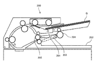
また、上述した実施形態および変形例の駆動装置は、例えば、図15に示す原稿自動搬送装置(ADF)200に用いることができる。例えば、図15に示す画像を読み取られた原稿Gを原稿排紙トレイ202へ搬送するか、原稿反転部203へ搬送するかを切り替える揺動部材たる切替爪203、正転および逆転する原稿反転部201の原稿反転駆動ローラ204、常に一方向に回転する原稿排紙ローラ205の駆動に上述した変形例1〜3の駆動装置を用いることができる。
Further, the drive devices of the above-described embodiments and modifications can be used, for example, in the automatic document feeder (ADF) 200 shown in FIG. For example, a switching
また、図16に示す画像形成装置100により画像形成された用紙を受け入れて、用紙に綴じ処理などの後処理を施す後処理装置に上述した駆動装置30を用いることができる。例えば、排紙トレイへの搬送経路Pt1と、綴じ処理ユニット303への搬送経路Pt2との間で搬送経路を揺動により切り替える切替爪305の駆動や、綴じ処理したされた用紙束の搬送経路を、中折りユニット304へ搬送する搬送経路Pt3と排紙トレイ308への搬送経路ptとの間で揺動により切り替える切替爪307の駆動に本実施形態の駆動装置を用いることもできる。また、排紙トレイ308への搬送路Pt1へ搬送されてきた用紙をスイッチバック搬送して、綴じ処理ユニット303へ搬送するための切替爪306と、正逆回転する搬送ローラ301や排紙ローラ302との駆動に変形例1〜3の駆動装置を用いることができる。
Further, the
また、切替爪に限らず、例えば、図17、図18に示すように、給紙トレイ24の底板24aを昇降させる揺動板24bの駆動に、本実施形態の駆動装置を用いることができる。また、揺動板24bと給紙ローラ13の駆動に本実施形態の駆動装置を用いることができる。
In addition to the switching claws, for example, as shown in FIGS. 17 and 18, the drive device of the present embodiment can be used to drive the
以上に説明したものは一例であり、以下の態様毎に特有の効果を奏する。
(態様1)
駆動モータ1などの駆動源と、揺動可能に設けられた切替爪23などの揺動部材が第一の姿勢と第二の姿勢とを選択的に取りうるように、揺動部材に駆動源の駆動力を伝達する駆動伝達手段と、駆動源の駆動を維持した状態で、揺動部材を第一の姿勢または第二の姿勢に保持する揺動保持手段とを備えた駆動装置において、前記駆動源の回転方向を変えずに前記揺動部材の揺動方向を切り替える揺動方向切替手段を備えた。
これによれば、揺動保持手段により駆動源の駆動を維持した状態で、揺動部材を第一の姿勢または第二の姿勢で保持でき、さらに、揺動方向切替手段により、駆動源の回転方向を変えずに揺動部材の揺動方向を切り替えることができる。これにより、駆動源を一方向に回転駆動させ続けて、揺動部材の姿勢を変更させることができ、揺動部材の姿勢を変更するときに駆動源の立ち上がり音が発生することがなく、装置の低騒音化を図ることができる。
What has been described above is merely an example, and each of the following aspects has unique effects.
(Aspect 1)
The driving source such as the
According to this, the rocking member can be held in the first posture or the second posture while the driving of the drive source is maintained by the swing holding means, and the rotation of the drive source is rotated by the swing direction switching means. The swinging direction of the swinging member can be switched without changing the direction. Accordingly, the posture of the swinging member can be changed by continuously rotating the drive source in one direction, and the rising noise of the drive source does not occur when the posture of the swinging member is changed. It is possible to reduce the noise.
(態様2)
態様1において、揺動部材は、搬送物を複数の搬送先のうちのいずれかへ案内する切替爪23などの搬送先案内部材である。
これによれば、搬送先案内部材を揺動させて用紙Pなどの搬送物の搬送先を切り替えるときに、モータの立ち上がり音が発生するのを防止することができ、装置の静音化を図ることができる。
(Aspect 2)
In the
According to this, when the conveyance destination guide member is swung to change the conveyance destination of the conveyance object such as the paper P, it is possible to prevent the rising noise of the motor from being generated, and to reduce the noise of the apparatus. You can
(態様3)
態様1または2において、前記揺動保持手段は、切替爪23などの揺動部材を前記第一の姿勢および前記第二の姿勢で止めるストッパ手段(本実施形態では、第一突き当て部材44aと第二突き当て部材44bとで構成)と、揺動部材への駆動伝達を制限する出力トルクリミッタ40などの駆動伝達制限手段とを有する。
これによれば、ストッパ手段により揺動部材の揺動が止められると、出力トルクリミッタ40などの駆動伝達制限手段により、揺動部材への駆動伝達が制御され、揺動部材が第一の姿勢または第二の姿勢で保持される。これにより、モータなどの駆動源の駆動を維持した状態で、揺動部材を第一の姿勢または第二の姿勢に保持することができる。
(Aspect 3)
In the first or second aspect, the swing holding means is a stopper means (in the present embodiment, a first abutting
According to this, when the rocking of the rocking member is stopped by the stopper means, the drive transmission to the rocking member is controlled by the drive transmission limiting means such as the
(態様4)
態様1乃至3いずれかにおいて、揺動方向切替手段(本実施形態では、第一駆動伝達経路R1、第二駆動伝達経路R2、各駆動伝達経路に設けられた電磁クラッチやトルクリミッタで構成された駆動経路切替手段からなる)を介して正逆回転する排紙反転駆動ローラ25などの正逆出力対象回転体にモータ31などの駆動源の駆動力を伝達する。
これによれば、ひとつの駆動源により、切替爪23などの揺動部材と正逆回転する排紙反転駆動ローラ25などの正逆出力対象回転体とを駆動することができ、揺動部材と正逆出力対象回転体とをそれぞれ別の駆動源により駆動するものに比べて、駆動源の数を減らすことができる。これにより、装置のコストダウンを図ることができる。また、装置の小型化を図ることができる。さらには、装置の低騒音化を図ることができる。
(Aspect 4)
In any one of
According to this, one drive source can drive the swinging member such as the switching
(態様5)
態様4において、出力対象回転体が、用紙をスイッチバック搬送したり、排紙部へ搬送したりする排紙反転駆動ローラ25などの排紙反転ローラである。
これにより、揺動方向切替手段の切替により、排紙反転ローラの回転方向を切り替えて、用紙を排紙部へ搬送したり、用紙をスイッチバック搬送して両面経路へ搬送したりすることができる。
(Aspect 5)
In the fourth aspect, the output target rotating body is a paper discharge reversing roller such as the paper discharge reversing
As a result, by switching the swinging direction switching means, it is possible to switch the rotation direction of the paper discharge reversing roller to carry the paper to the paper discharge unit, or switch the paper back and carry it to the double-sided path. ..
(態様6)
態様1乃至5いずれかにおいて、一方向にのみ回転する定着ローラ17aなどの一方向出力対象回転体にモータ31などの駆動源の駆動力を伝達する駆動伝達経路(本実施形態では、定着ギヤ52などで構成)を備えた。
これによれば、ひとつの駆動源で、切替爪23などの揺動部材と定着ローラ17aなどの一方向出力対象回転体とを駆動することができ、揺動部材と一方向出力対象回転体とをそれぞれ別の駆動源により駆動するものに比べて、駆動源の数を減らすことができる。これにより、装置のコストダウンを図ることができる。また、装置の小型化を図ることができる。さらには、装置の低騒音化を図ることができる。
(Aspect 6)
In any one of
According to this, the swinging member such as the switching
(態様7)
態様1乃至6いずれかにおいて、駆動伝達手段は、揺動方向切替手段から駆動力が出力される出力軸tなどの駆動出力部材を備え、駆動出力部材を介して前記揺動部材へ駆動力を伝達するものであり、駆動出力部材に対して切替爪23などの揺動部材が増速するように、駆動出力部材から揺動部材へ駆動伝達が行われる。
これによれば、図7を用いて説明したように、切替爪23などの揺動部材をすばやく揺動させることができる。
(Aspect 7)
In any one of
According to this, as described with reference to FIG. 7, the swing member such as the switching
(態様8)
態様1乃至6いずれかにおいて、駆動伝達手段は、揺動方向切替手段から駆動力が出力される出力軸tなどの駆動出力部材を備え、駆動出力部材に対して切替爪23などの揺動部材が減速するように、前記駆動出力部材から前記揺動部材へ駆動伝達が行われる。
これによれば、図8を用いて説明したように切替爪23などの揺動部材をゆっくりと揺動させることができ、突き当て部材44a,44bに突き当たったときの衝撃音を低減することができ、装置の低騒音化を図ることができる。
(Aspect 8)
In any one of
According to this, as described with reference to FIG. 8, the swinging member such as the switching
(態様9)
態様1乃至8いずれかにおいて、前記駆動伝達手段は、揺動方向切替手段から駆動力が出力される排紙反転駆動ローラ25の軸25aなどの駆動出力部材を備え、駆動出力部材を介して前記揺動部材へ駆動力を伝達するものであり、切替爪23などの揺動部材の揺動軸方向の一端側に駆動出力部材から前記揺動部材へ駆動力を伝達する伝達機構(出力ギヤ39、揺動ギヤ43および出力トルクリミッタ40)を配置し、前記揺動軸方向の他端側に前記回転方向切替手段(第一駆動伝達経路R1、第二駆動伝達経路R2および、電磁クラッチやトルクリミッタなどにより構成された経路切替手段)を配置した。
これによれば、変形例1で説明したように、駆動出力部材から前記揺動部材へ駆動力を伝達する伝達機構と、回転方向切替手段とを揺動軸方向の一端側に配置した場合に比べて、駆動装置が搭載される装置の軸方向の小型化を図ることができる。
(Aspect 9)
In any one of
According to this, as described in the first modification, when the transmission mechanism for transmitting the driving force from the drive output member to the swing member and the rotation direction switching means are arranged at one end side in the swing axis direction. In comparison, it is possible to reduce the axial size of the device in which the drive device is mounted.
(態様10)
態様1乃至9いずれかにおいて、前記駆動伝達手段は、揺動方向切替手段から駆動力が出力される出力軸tなどの駆動出力部材を備え、駆動出力部材を介して前記揺動部材へ駆動力を伝達するものであり、駆動出力部材から切替爪23などの揺動部材への駆動伝達をギヤの噛み合いで行う。
これによれば、安価な構成で駆動出力部材から揺動部材への駆動伝達を行うことができる。
(Aspect 10)
In any one of
According to this, it is possible to transmit the drive from the drive output member to the swing member with an inexpensive configuration.
(態様11)
態様1乃至9いずれかにおいて、前記駆動伝達手段は、揺動方向切替手段から駆動力が出力される排紙反転駆動ローラ25の軸25aなどの駆動出力部材を備え、駆動出力部材を介して前記揺動部材へ駆動力を伝達するものであり、駆動出力部材から切替爪23などの揺動部材への駆動伝達がベルトを介して行われる。
これによれば、変形例2で説明したように、駆動出力部材と揺動部材との距離が離れていても、駆動出力部材に設けたプーリと、揺動部材に設けたプーリとこれらに張架されたタイミングベルトなどのベルト部材とで、駆動伝達を行うことができる。ギヤの噛み合いで駆動伝達を行う場合、3部材で駆動伝達可能とすると、ギヤの直径を大きくする必要があり装置大型化してしまうが、ベルトを介した駆動伝達とすることで、大型化することなく、3部材で駆動出力部材から離れた位置に配置された揺動部材に駆動伝達を行うことができる。
(Aspect 11)
In any one of
According to this, as described in the second modification, even if the drive output member and the swinging member are separated from each other, the pulley provided on the drive output member, the pulley provided on the swinging member, and the pulleys provided on the swinging member are stretched. Drive transmission can be performed with a belt member such as a timing belt that is mounted. When the drive transmission is performed by meshing the gears, if the drive transmission is possible with three members, the diameter of the gear needs to be increased and the size of the apparatus increases, but the drive transmission via a belt increases the size. Instead, the drive transmission can be performed by the three members to the swinging member arranged at a position apart from the drive output member.
(態様12)
態様1乃至11において、前記揺動方向切替手段は、前記揺動部材を互いに異なる方向に揺動させる二系統の駆動伝達経路と、前記二系統の駆動伝達経路の間で選択的に駆動伝達経路を切り替える経路切替手段(一方の駆動伝達経路に配置した電磁クラッチと他方の駆動伝達経路に配置したトルクリミッタなどにより構成)とを有する。
これによれば、経路切替手段により駆動出力部材への駆動伝達経路を切り替えることで、駆動出力部材を互いに異なる方向に回転駆動させることができる。これにより、モータを一方向に回転させた状態で、揺動部材を互いに異なる方向に揺動させることができる。
(Aspect 12)
In
According to this, the drive output member can be rotationally driven in different directions by switching the drive transmission route to the drive output member by the route switching means. Thus, the swing member can swing in different directions while the motor is rotating in one direction.
(態様13)
態様12において、経路切り替え手段は、各駆動伝達経路に設けられ、駆動力を伝達する状態と駆動力の伝達を遮断する状態とを切り替え可能な複数の電磁クラッチなど駆動伝達切替手段を備える。
これによれば、変形例1で説明したように、各駆動伝達経路の電磁クラッチなどの駆動伝達切替手段を制御することにより駆動伝達経路を切り替えることができる。
(Aspect 13)
In a twelfth aspect, the path switching means includes drive transmission switching means such as a plurality of electromagnetic clutches provided in each drive transmission path and capable of switching between a state for transmitting the driving force and a state for interrupting the transmission of the driving force.
According to this, as described in the
(態様14)
態様13において、各駆動伝達経路の電磁クラッチなどの駆動伝達切替手段を、互いに異なる軸上に配置した。
これによれば、変形例2で説明したように、各駆動伝達経路の電磁クラッチなどの駆動伝達切替手段を同軸上に設けた場合に比べて、軸方向の小型化を図ることができる。
(Aspect 14)
In the thirteenth aspect, the drive transmission switching means such as the electromagnetic clutch of each drive transmission path is arranged on different axes.
According to this, as described in the second modification, it is possible to reduce the size in the axial direction as compared with the case where the drive transmission switching means such as the electromagnetic clutch of each drive transmission path is provided coaxially.
(態様15)
態様13において、各駆動伝達経路の電磁クラッチなどの駆動伝達切替手段を、同軸上に配置した。
これによれば、変形例1で説明したように、電磁クラッチなどの駆動伝達切替手段が取り付けられている軸にのみ、作業者がアクセス可能に画像形成装置などの速度切替装置が搭載される装置を構成すれば、各駆動伝達経路の駆動伝達切り替え手段の交換を行うことができる。これにより、互いに異なる回転軸に駆動伝達切り替え手段を取り付けた構成に比べて、駆動装置が搭載される装置の小型化を図ることができる。
(Aspect 15)
In the thirteenth aspect, drive transmission switching means such as an electromagnetic clutch of each drive transmission path is arranged coaxially.
According to this, as described in the modified example 1, a device in which a speed switching device such as an image forming device is mounted so that a worker can access only a shaft to which drive transmission switching means such as an electromagnetic clutch is attached. With this configuration, the drive transmission switching means of each drive transmission path can be replaced. As a result, it is possible to reduce the size of the device in which the drive device is mounted, as compared with the configuration in which the drive transmission switching means is attached to different rotating shafts.
(態様16)
態様12において、前記経路切替手段は、駆動力を伝達する状態と駆動力の伝達を遮断する状態とを切り替え可能な電磁クラッチなどの駆動伝達切替手段を一方の駆動伝達経路に設け、駆動伝達を制限する第二トルクリミッタ33などの切替用駆動駆動伝達制限手段を他方の駆動伝達経路に設けた。
これによれば、実施形態で説明したように、駆動伝達切替手段による一方の駆動伝達経路の駆動伝達状態のときは、第二トルクリミッタ33などの切替用駆動駆動伝達制限手段により駆動伝達が制限され、駆動伝達切替手段による一方の駆動伝達経路の駆動伝達が遮断されたときは、切替用駆動駆動伝達制限手段により駆動伝達が許容され、他方の駆動伝達経路から出力駆動伝達部材への駆動伝達が行われる。これにより、一方の駆動伝達経路と他方の駆動伝達経路との間で駆動伝達経路の切り替えを行うことができる。よって、一つの駆動伝達切り替え手段の切り替え動作に要する時間で、出力駆動伝達部材への駆動伝達経路の切り替えを行うことができる。したがって、前記二系統の駆動伝達経路それぞれに対応させて駆動伝達切り替え手段を二つ設ける場合よりも、駆動伝達経路の切り替えにかかる時間の短縮化を図ることができる。
(Aspect 16)
In a twelfth aspect, the path switching means is provided with a drive transmission switching means such as an electromagnetic clutch capable of switching between a state in which the driving force is transmitted and a state in which the transmission of the driving force is cut off, in one of the drive transmission paths so that the drive transmission is performed. A switching drive drive transmission limiting means such as a limiting
According to this, as described in the embodiment, when the drive transmission switching means is in the drive transmission state of one drive transmission path, the drive transmission is limited by the switching drive drive transmission limiting means such as the
(態様17)
態様16において、電磁クラッチなどの駆動伝達切替手段とトルクリミッタなどの前記切替用駆動駆動伝達制限手段とを互いに異なる軸上に配置した。
これによれば、変形例3で説明したように、駆動伝達切替手段と切替用駆動駆動伝達制限手段とを同軸に配置した場合に比べて、軸方向の小型化を図ることができる。
(Aspect 17)
In the sixteenth aspect, the drive transmission switching means such as an electromagnetic clutch and the switching drive drive transmission limiting means such as a torque limiter are arranged on different axes.
According to this, as described in the third modification, it is possible to reduce the size in the axial direction as compared with the case where the drive transmission switching unit and the switching drive drive transmission limiting unit are arranged coaxially.
(態様18)
態様16において、電磁クラッチなどの駆動伝達切替手段とトルクリミッタなどの切替用駆動駆動伝達制限手段とを同軸上に配置した。
これによれば、実施形態で説明したように、軸受けなどを介して回転可能に支持する軸の削減を図ることが可能になり、装置のコストダウンを図ることができる。
(Aspect 18)
In the sixteenth aspect, drive transmission switching means such as an electromagnetic clutch and switching drive drive transmission limiting means such as a torque limiter are arranged coaxially.
According to this, as described in the embodiment, it is possible to reduce the number of shafts that are rotatably supported via bearings and the like, and it is possible to reduce the cost of the device.
(態様19)
態様16乃至18いずれかにおいて、前記揺動保持手段は、前記揺動部材への駆動伝達を制限する出力トルクリミッタ40などの駆動伝達制限手段を有し、前記駆動伝達制限手段の駆動制限値を、第二出力トルクリミッタ33などの切替用駆動駆動伝達制限手段の駆動制限値よりも小さくした。
これによれば、実施形態で説明したように、切替爪23などの揺動部材が前記ストッパ手段により止められたときに、第二トルクリミッタ33などの切替用駆動駆動伝達制限手段により駆動伝達が制限される前に、出力トルクリミッタ40などの駆動伝達制限手段の駆動伝達が制限される。これにより、切替爪23などの揺動部材が前記ストッパ手段により止められても、第二トルクリミッタ33などの切替用駆動駆動伝達制限手段から駆動伝達を行うことができる。
(Aspect 19)
In any one of Modes 16 to 18, the swing holding means includes drive transmission limiting means such as an
According to this, as described in the embodiment, when the swinging member such as the switching
(態様20)
態様13乃至19いずれかにおいて、電磁クラッチなどの駆動伝達切替手段に駆動連結される第一入力プーリ35などの被駆動連結部材を、前記駆動伝達切替手段と同軸上に配置した。
これによれば、実施形態で説明したように、第一入力プーリ35などの被駆動連結部材が軸に対して傾くのを抑制することができる。
(Aspect 20)
In any one of
According to this, as described in the embodiment, it is possible to prevent the driven connecting member such as the
(態様21)
態様1乃至20いずれかにおいて、モータ31などの駆動源のモータギヤ31aなどの出力ギヤを、内歯歯車と噛み合せた。
これによれば、変形例2で説明したように、モータギヤ31aなどの出力ギヤとの噛み合い率が高まり、回転ムラや騒音・振動の発生を抑制することができる。また、出力ギヤとの噛み合い部を内歯歯車で覆うことができ、噛み合い騒音を内歯歯車により遮蔽することができ、装置の静音化を図ることができる。
(Aspect 21)
In any one of
According to this, as described in the second modification, the meshing ratio with the output gear such as the
(態様22)
切替爪23などの揺動部材を備え、揺動部材を揺動することで、用紙Pなどの搬送物を複数の搬送先のうちのいずれかに搬送されるように案内する搬送装置において、揺動部材を駆動する駆動手段として、態様1乃至21いずれかに記載の駆動装置を用いた。
これによれば、搬送装置の静音化を図ることができる。
(Aspect 22)
In a transport device that includes a swing member such as the switching
According to this, it is possible to reduce the noise of the transport device.
(態様23)
画像を形成する画像形成手段と、揺動部材を駆動する駆動手段とを備えた画像形成装置において、前記駆動手段として、態様1乃至22のいずれかに記載の駆動装置を用いた。
これによれば、画像形成装置の静音化を図ることができる。
(Aspect 23)
In the image forming apparatus including the image forming unit that forms an image and the driving unit that drives the swinging member, the driving unit according to any one of
According to this, it is possible to reduce the noise of the image forming apparatus.
1:画像形成ユニット
2:感光体
3:露光装置
4:現像装置
5:現像剤カートリッジ
6:クリーニング装置
10:中間転写ユニット
11:中間転写ベルト
12:一次転写ローラ
13:給紙ローラ
14:レジストローラ対
15:二次転写ローラ
16:二次転写装置
17:定着装置
17a:定着ローラ
17b:加圧ローラ
18:排紙部
18a:排紙従動ローラ
19:反転部
19a:反転従動ローラ
20:排紙トレイ
21:両面搬送路
22:給紙搬送路
23:切替爪
23a:揺動軸
24:給紙トレイ
24a:底板
24b:揺動板
25:排紙反転駆動ローラ
25a:排紙反転駆動ローラの軸
30:駆動装置
31:モータ
31a:モータギヤ
32:第二入力ギヤ
33:第二トルクリミッタ
33a:連結爪
34:第二出力ギヤ
34a:連結穴
35:第一入力プーリ
36:第一出力プーリ
36a:連結穴
37:第一電磁クラッチ
37a:連結爪
37b:アーマチュア
37c:ロータ部
37d:電磁コイル部
37e:軸固定部
37f:駆動連結部材
38:第一タイミングベルト
39:出力ギヤ
40:出力トルクリミッタ
40a:連結爪
41:ブラケット
41a:軸受
41b:軸受
42:側板
43:揺動ギヤ
44a:第一突き当て部材
44b:第二突き当て部材
51:第二電磁クラッチ
52:定着ギヤ
55:側板
55a:軸受
61:駆動アイドラギヤ
62:駆動出力ギヤ
63:定着出力ギヤ
63a:第一ギヤ部
63b:第二ギヤ部
100:レーザプリンタ(画像形成装置)
131:第二入力プーリ
132:第二タイミングベルト
133:第二出力プーリ
135:第一入力ギヤ
136:第一出力ギヤ
138:第一アイドラギヤ
139:切替入力プーリ
142:切替タイミングベルト
143:切替出力プーリ
171:定着ローラの軸
202:原稿排紙トレイ
203:切替爪
203:原稿反転部
204:原稿反転駆動ローラ
205:原稿排紙ローラ
301:搬送ローラ
302:排紙ローラ
303:綴じ処理ユニット
304:中折りユニット
305:切替爪
306:切替爪
307:切替爪
308:排紙トレイ
G:原稿
P:用紙
R1:第一駆動伝達経路
R2:第二駆動伝達経路
s:固定軸
t:出力軸
u1,u2:取り付けピン
v:定着固定軸
W:第二固定軸
X:回転軸
1: image forming unit 2: photoconductor 3: exposure device 4: developing device 5: developer cartridge 6: cleaning device 10: intermediate transfer unit 11: intermediate transfer belt 12: primary transfer roller 13: paper feed roller 14: registration roller Pair 15: Secondary transfer roller 16: Secondary transfer device 17: Fixing device 17a: Fixing roller 17b: Pressurizing roller 18: Paper ejection unit 18a: Paper ejection driven roller 19: Reversing unit 19a: Reversal driven roller 20: Paper ejection Tray 21: Double-sided transport path 22: Paper feed transport path 23: Switching claw 23a: Swing shaft 24: Paper feed tray 24a: Bottom plate 24b: Swing plate 25: Paper ejection reversal drive roller 25a: Paper ejection reversal drive roller axis 30: drive device 31: motor 31a: motor gear 32: second input gear 33: second torque limiter 33a: connecting claw 34: second output gear 34a: connecting hole 35: first input pulley 36: first output pulley 36a: Connection hole 37: First electromagnetic clutch 37a: Connection claw 37b: Armature 37c: Rotor part 37d: Electromagnetic coil part 37e: Shaft fixing part 37f: Drive connection member 38: First timing belt 39: Output gear 40: Output torque limiter 40a : Connection claw 41: Bracket 41a: Bearing 41b: Bearing 42: Side plate 43: Swing gear 44a: First abutting member 44b: Second abutting member 51: Second electromagnetic clutch 52: Fixing gear 55: Side plate 55a: Bearing 61: drive idler gear 62: drive output gear 63: fixing output gear 63a: first gear portion 63b: second gear portion 100: laser printer (image forming apparatus)
131: second input pulley 132: second timing belt 133: second output pulley 135: first input gear 136: first output gear 138: first idler gear 139: switching input pulley 142: switching timing belt 143: switching output pulley 171: fixing roller shaft 202: document discharge tray 203: switching claw 203: document reversing unit 204: document reversing drive roller 205: document discharge roller 301: conveyance roller 302: discharge roller 303: binding processing unit 304: middle Folding unit 305: Switching claw 306: Switching claw 307: Switching claw 308: Paper ejection tray G: Document P: Paper R1: First drive transmission path R2: Second drive transmission path s: Fixed axis t: Output axes u1, u2 : Mounting pin v: Fixing fixed shaft W: Second fixed shaft X: Rotating shaft
Claims (23)
揺動可能に設けられた揺動部材が第一の姿勢と第二の姿勢とを選択的に取りうるように、前記揺動部材に前記駆動源の駆動力を伝達する駆動伝達手段と、
前記駆動源の駆動を維持した状態で、前記揺動部材を前記第一の姿勢または前記第二の姿勢に保持する揺動保持手段とを備えた駆動装置において、
前記駆動源の回転方向を変えずに前記揺動部材の揺動方向を切り替える揺動方向切替手段を備え、
前記揺動保持手段は、前記揺動部材を前記第一の姿勢および前記第二の姿勢で止めるストッパ手段と、前記揺動部材への駆動伝達を制限する駆動伝達制限手段とを有し、
前記駆動伝達制限手段は、トルクリミッタであることを特徴とする駆動装置。 Drive source,
Drive transmission means for transmitting the driving force of the drive source to the swing member so that the swing member provided swingably can take a first posture and a second posture selectively;
A drive device including a swing holding unit that holds the swing member in the first posture or the second posture in a state where the driving of the driving source is maintained,
A swing direction switching means for switching the swing direction of the swing member without changing the rotation direction of the drive source ;
The swing holding means includes stopper means for stopping the swing member in the first posture and the second posture, and drive transmission limiting means for limiting drive transmission to the swing member,
The drive device, wherein the drive transmission limiting means is a torque limiter .
前記揺動部材は、搬送物を複数の搬送先のうちのいずれかへ案内する搬送先案内部材であることを特徴とする駆動装置。 The drive device according to claim 1,
The drive device is characterized in that the swinging member is a destination guide member that guides an object to be transported to one of a plurality of destinations .
前記揺動方向切替手段を介して、正逆回転する正逆出力対象回転体に前記駆動源の前記駆動力を伝達することを特徴とする駆動装置。 The drive device according to 請 Motomeko 1 or 2,
A drive device for transmitting the driving force of the drive source to a forward/reverse output target rotating body that rotates in a forward/reverse direction, via the swing direction switching means.
前記正逆出力対象回転体が、用紙をスイッチバック搬送したり、排紙部へ搬送したりする排紙反転ローラであることを特徴とする駆動装置。 The drive device according to claim 3 ,
The drive device, wherein the normal/reverse output target rotating body is a paper discharge reversing roller that carries out switchback conveyance of the paper or conveys the paper to a paper ejection unit.
一方向にのみ回転する一方向出力対象回転体に前記駆動源の駆動力を伝達する駆動伝達経路を備えたことを特徴とする駆動装置。 The drive device according to one of claims 1 to 4 have shifted,
A drive device comprising a drive transmission path for transmitting the drive force of the drive source to a one-way output target rotating body that rotates only in one direction.
前記駆動伝達手段は、揺動方向切替手段から駆動力が出力される駆動出力部材を備え、駆動出力部材を介して前記揺動部材へ駆動力を伝達するものであり、
前記駆動出力部材の回転速度に対して前記揺動部材が増速するように、前記駆動出力部材から前記揺動部材へ駆動伝達が行われることを特徴とする駆動装置。 The drive device according to one of claims 1 to 5 have displacement,
The drive transmission means includes a drive output member for outputting a drive force from the swing direction switching means, and transmits the drive force to the swing member via the drive output member,
A drive device is characterized in that drive is transmitted from the drive output member to the swing member so that the swing member accelerates with respect to a rotation speed of the drive output member.
前記駆動伝達手段は、揺動方向切替手段から駆動力が出力される駆動出力部材を備え、駆動出力部材を介して前記揺動部材へ駆動力を伝達するものであり、
前記駆動出力部材の回転速度に対して前記揺動部材が減速するように、前記駆動出力部材から前記揺動部材へ駆動伝達が行われることを特徴とする駆動装置。 The drive device according to one of claims 1 to 5 have displacement,
The drive transmission means includes a drive output member for outputting a drive force from the swing direction switching means, and transmits the drive force to the swing member via the drive output member,
A drive device is characterized in that drive is transmitted from the drive output member to the swing member so that the swing member is decelerated with respect to the rotation speed of the drive output member.
前記駆動伝達手段は、揺動方向切替手段から駆動力が出力される駆動出力部材を備え、駆動出力部材を介して前記揺動部材へ駆動力を伝達するものであり、
前記揺動部材の揺動軸方向の一端側に前記駆動出力部材から前記揺動部材へ駆動力を伝達する伝達機構を配置し、前記揺動軸方向の他端側に前記揺動方向切替手段を配置したことを特徴とする駆動装置。 The drive device according to one of claims 1 to 7 have shifted,
The drive transmission means includes a drive output member for outputting a drive force from the swing direction switching means, and transmits the drive force to the swing member via the drive output member,
A transmission mechanism for transmitting a driving force from the drive output member to the swing member is arranged on one end side of the swing member in the swing axis direction, and the swing direction switching means is arranged on the other end side of the swing axis direction. A drive device characterized in that.
前記駆動伝達手段は、揺動方向切替手段から駆動力が出力される駆動出力部材を備え、駆動出力部材を介して前記揺動部材へ駆動力を伝達するものであり、
前記駆動出力部材から前記揺動部材への駆動伝達をギヤの噛み合いで行うことを特徴とする駆動装置。 The drive device according to one of claims 1 to 8 have shifted,
The drive transmission means includes a drive output member for outputting a drive force from the swing direction switching means, and transmits the drive force to the swing member via the drive output member,
A drive device, wherein drive transmission from the drive output member to the swing member is performed by meshing gears.
前記駆動伝達手段は、揺動方向切替手段から駆動力が出力される駆動出力部材を備え、駆動出力部材を介して前記揺動部材へ駆動力を伝達するものであり、
前記駆動出力部材から前記揺動部材への駆動伝達がベルトを介して行われることを特徴とする駆動装置。 The drive device according to one of claims 1 to 8 have shifted,
The drive transmission means includes a drive output member for outputting a drive force from the swing direction switching means, and transmits the drive force to the swing member via the drive output member,
The drive device is characterized in that drive transmission from the drive output member to the swing member is performed via a belt.
前記揺動方向切替手段は、前記揺動部材を互いに異なる方向に揺動させる二系統の駆動伝達経路と、前記二系統の駆動伝達経路の間で選択的に駆動伝達経路を切り替える経路切替手段とを有することを特徴とする駆動装置。 The drive device according to one of claims 1 to 10 have shifted,
The swinging direction switching means includes a two-system drive transmission path that swings the swinging member in different directions, and a path switching means that selectively switches the drive transmission path between the two system drive transmission paths. A drive device comprising:
前記経路切替手段は、各駆動伝達経路に設けられ、駆動力を伝達する状態と駆動力の伝達を遮断する状態とを切り替え可能な複数の駆動伝達切替手段を備えることを特徴とする駆動装置。 The drive device according to claim 11 ,
The path switching means includes a plurality of drive transmission switching means provided on each drive transmission path and capable of switching between a state for transmitting the driving force and a state for interrupting the transmission of the driving force.
各駆動伝達経路の駆動伝達切替手段を、互いに異なる軸上に配置したことを特徴とする駆動装置。 The drive device according to claim 12 ,
A drive device characterized in that drive transmission switching means of each drive transmission path are arranged on mutually different axes.
各駆動伝達経路の駆動伝達切替手段を、同軸上に配置したことを特徴とする駆動装置。 The drive device according to claim 12 ,
A drive device characterized in that drive transmission switching means of each drive transmission path are arranged coaxially.
前記経路切替手段は、駆動力を伝達する状態と駆動力の伝達を遮断する状態とを切り替え可能な駆動伝達切替手段を一方の駆動伝達経路に設け、駆動伝達を制限する切替用駆動伝達制限手段を他方の駆動伝達経路に設けたことを特徴とする駆動装置。 The drive device according to claim 11 ,
The path switching means is provided with a drive transmission switching means capable of switching between a state in which the driving force is transmitted and a state in which the transmission of the driving force is cut off, in one of the drive transmission paths, and the drive transmission limiting means for switching is arranged to limit the drive transmission. Is provided in the other drive transmission path.
前記駆動伝達切替手段と前記切替用駆動伝達制限手段とを互いに異なる軸上に配置したことを特徴とする駆動装置。 The drive device according to claim 15 ,
A drive device in which the drive transmission switching means and the switching drive transmission limiting means are arranged on mutually different axes.
前記駆動伝達切替手段と前記切替用駆動伝達制限手段とを同軸上に配置したことを特徴とする駆動装置。 The drive device according to claim 15 ,
A drive device in which the drive transmission switching means and the switching drive transmission limiting means are arranged coaxially.
前記駆動伝達制限手段の駆動制限値を、前記切替用駆動伝達制限手段の駆動制限値よりも小さくしたことを特徴とする駆動装置。 The drive device according to any one of claims 15 to 17 ,
Before SL drive limit value of the drive transmission limiting means driving device characterized by being smaller than the driving limit of the switching drive transmission limiting means.
揺動可能に設けられた揺動部材が第一の姿勢と第二の姿勢とを選択的に取りうるように、前記揺動部材に前記駆動源の駆動力を伝達する駆動伝達手段と、Drive transmission means for transmitting the driving force of the drive source to the swing member so that the swing member provided swingably can take a first posture and a second posture selectively;
前記駆動源の駆動を維持した状態で、前記揺動部材を前記第一の姿勢または前記第二の姿勢に保持する揺動保持手段とを備えた駆動装置において、A drive device including a swing holding unit that holds the swing member in the first posture or the second posture in a state where the driving of the driving source is maintained,
前記駆動源の回転方向を変えずに前記揺動部材の揺動方向を切り替える揺動方向切替手段を備え、A swing direction switching means for switching the swing direction of the swing member without changing the rotation direction of the drive source;
前記揺動方向切替手段は、前記揺動部材を互いに異なる方向に揺動させる二系統の駆動伝達経路と、前記二系統の駆動伝達経路の間で選択的に駆動伝達経路を切り替える経路切替手段とを有し、The swinging direction switching means includes a two-system drive transmission path that swings the swinging member in different directions, and a path switching means that selectively switches the drive transmission path between the two system drive transmission paths. Have
前記経路切替手段は、駆動力を伝達する状態と駆動力の伝達を遮断する状態とを切り替え可能な駆動伝達切替手段を一方の駆動伝達経路に設け、駆動伝達を制限する切替用駆動伝達制限手段を他方の駆動伝達経路に設け、The path switching means is provided with a drive transmission switching means capable of switching between a state in which the driving force is transmitted and a state in which the transmission of the driving force is cut off, in one of the drive transmission paths, and the drive transmission limiting means for switching is arranged to limit the drive transmission. Is provided in the other drive transmission path,
前記揺動保持手段は、前記揺動部材への駆動伝達を制限する駆動伝達制限手段を有し、The swing holding means has drive transmission limiting means for limiting drive transmission to the swing member,
前記駆動伝達制限手段の駆動制限値を、前記切替用駆動伝達制限手段の駆動制限値よりも小さくしたことを特徴とする駆動装置。A drive device, wherein a drive limit value of the drive transmission limiter is set smaller than a drive limit value of the switching drive transmission limiter.
前記駆動伝達切替手段に駆動連結される被駆動連結部材を、前記駆動伝達切替手段と同軸上に配置したことを特徴とする駆動装置。 The drive device according to any one of claims 12 to 19,
A drive device, wherein a driven connecting member drivingly connected to the drive transmission switching means is arranged coaxially with the drive transmission switching means.
前記駆動源の出力ギヤを、内歯歯車と噛み合せたことを特徴とする駆動装置。 The drive device according to any one of claims 1 to 20,
A drive device in which an output gear of the drive source is meshed with an internal gear.
前記揺動部材を駆動する駆動手段として、請求項1乃至21いずれかに記載の駆動装置を用いたことを特徴とする搬送装置。 A transport device that includes a swing member, and swings the swing member to guide a transported object to be transported to one of a plurality of transport destinations,
A transport device, wherein the drive device according to any one of claims 1 to 21 is used as drive means for driving the swing member.
揺動部材を駆動する駆動手段とを備えた画像形成装置において、
前記駆動手段として、請求項1乃至21のいずれかに記載の駆動装置を用いたことを特徴とする画像形成装置。 An image forming means for forming an image,
In an image forming apparatus including a drive unit that drives the swing member,
As the driving means, the image forming apparatus characterized by using the driving device according to any one of claims 1 to 21.
Priority Applications (1)
| Application Number | Priority Date | Filing Date | Title |
|---|---|---|---|
| JP2016087543A JP6703761B2 (en) | 2016-04-25 | 2016-04-25 | Drive device, transport device, and image forming apparatus |
Applications Claiming Priority (1)
| Application Number | Priority Date | Filing Date | Title |
|---|---|---|---|
| JP2016087543A JP6703761B2 (en) | 2016-04-25 | 2016-04-25 | Drive device, transport device, and image forming apparatus |
Publications (3)
| Publication Number | Publication Date |
|---|---|
| JP2017197307A JP2017197307A (en) | 2017-11-02 |
| JP2017197307A5 JP2017197307A5 (en) | 2019-03-28 |
| JP6703761B2 true JP6703761B2 (en) | 2020-06-03 |
Family
ID=60238916
Family Applications (1)
| Application Number | Title | Priority Date | Filing Date |
|---|---|---|---|
| JP2016087543A Active JP6703761B2 (en) | 2016-04-25 | 2016-04-25 | Drive device, transport device, and image forming apparatus |
Country Status (1)
| Country | Link |
|---|---|
| JP (1) | JP6703761B2 (en) |
Families Citing this family (2)
| Publication number | Priority date | Publication date | Assignee | Title |
|---|---|---|---|---|
| JP2019172405A (en) * | 2018-03-27 | 2019-10-10 | ブラザー工業株式会社 | Image forming apparatus |
| JP2023107565A (en) * | 2022-01-24 | 2023-08-03 | 株式会社リコー | Drive transmission device, drive unit and image formation apparatus |
Family Cites Families (5)
| Publication number | Priority date | Publication date | Assignee | Title |
|---|---|---|---|---|
| JP4311665B2 (en) * | 2004-09-17 | 2009-08-12 | 株式会社リコー | Paper branching apparatus and image forming apparatus |
| JP2007076881A (en) * | 2005-09-16 | 2007-03-29 | Ricoh Printing Systems Ltd | Image forming device |
| JP2008162714A (en) * | 2006-12-27 | 2008-07-17 | Kyocera Mita Corp | Course changing mechanism for recording medium and image forming device having same |
| JP5904397B2 (en) * | 2011-11-01 | 2016-04-13 | 株式会社リコー | Sheet conveying apparatus and image forming apparatus |
| JP6071971B2 (en) * | 2013-10-18 | 2017-02-01 | キヤノン株式会社 | Sheet conveying apparatus and image forming apparatus |
-
2016
- 2016-04-25 JP JP2016087543A patent/JP6703761B2/en active Active
Also Published As
| Publication number | Publication date |
|---|---|
| JP2017197307A (en) | 2017-11-02 |
Similar Documents
| Publication | Publication Date | Title |
|---|---|---|
| US9046844B2 (en) | Duplex printer with a unidirectional drive source and a gear train with a partially toothed gear | |
| JP2011140980A (en) | Drive mechanism for conveyance roller, double-sided unit, and image forming apparatus | |
| JP6703761B2 (en) | Drive device, transport device, and image forming apparatus | |
| US8939448B2 (en) | Image forming apparatus | |
| JP3520169B2 (en) | Image forming device | |
| JP2016108135A (en) | Drive device and image formation apparatus | |
| JP2016098052A (en) | Recording medium conveyance device and image formation apparatus | |
| JP6046179B2 (en) | Image forming apparatus | |
| JP2019210084A (en) | Sheet conveying device and image forming device having the same, and sheet conveying method | |
| JP6519845B2 (en) | Drive device and image forming apparatus | |
| JP2007322786A (en) | Image forming apparatus | |
| JP6044432B2 (en) | Drive switching mechanism, rotational drive device using the same, and drive processing device | |
| JP2010175044A (en) | Drive transmission device and image formation device equipped with the same | |
| JP2008002477A (en) | Driving force transmitting member and image forming device | |
| JP6544618B2 (en) | Drive device and image forming apparatus | |
| JP6697710B2 (en) | Speed switching device, drive device and image forming device | |
| JP6731194B2 (en) | Driving device and image forming apparatus | |
| US20200387105A1 (en) | Driving force transmission device and image forming apparatus | |
| JP2002189322A (en) | Image forming device | |
| JP2024000265A (en) | Image forming device | |
| JP2006290589A (en) | Conveying passage switching mechanism and image forming apparatus having it | |
| JP2017190223A (en) | Drive device and image forming apparatus | |
| JP2019167248A (en) | Drive device and image formation apparatus | |
| JP2007033620A (en) | Gap holding member and image forming apparatus | |
| JP4366305B2 (en) | Drive unit and image forming apparatus |
Legal Events
| Date | Code | Title | Description |
|---|---|---|---|
| A621 | Written request for application examination |
Free format text: JAPANESE INTERMEDIATE CODE: A621 Effective date: 20190208 |
|
| A521 | Written amendment |
Free format text: JAPANESE INTERMEDIATE CODE: A523 Effective date: 20190212 |
|
| A977 | Report on retrieval |
Free format text: JAPANESE INTERMEDIATE CODE: A971007 Effective date: 20191219 |
|
| A131 | Notification of reasons for refusal |
Free format text: JAPANESE INTERMEDIATE CODE: A131 Effective date: 20191227 |
|
| A521 | Written amendment |
Free format text: JAPANESE INTERMEDIATE CODE: A523 Effective date: 20200220 |
|
| TRDD | Decision of grant or rejection written | ||
| A01 | Written decision to grant a patent or to grant a registration (utility model) |
Free format text: JAPANESE INTERMEDIATE CODE: A01 Effective date: 20200410 |
|
| A61 | First payment of annual fees (during grant procedure) |
Free format text: JAPANESE INTERMEDIATE CODE: A61 Effective date: 20200423 |
|
| R151 | Written notification of patent or utility model registration |
Ref document number: 6703761 Country of ref document: JP Free format text: JAPANESE INTERMEDIATE CODE: R151 |