JP6701323B2 - Dispensing device and system for solid chemical cleaning agents - Google Patents
Dispensing device and system for solid chemical cleaning agents Download PDFInfo
- Publication number
- JP6701323B2 JP6701323B2 JP2018508723A JP2018508723A JP6701323B2 JP 6701323 B2 JP6701323 B2 JP 6701323B2 JP 2018508723 A JP2018508723 A JP 2018508723A JP 2018508723 A JP2018508723 A JP 2018508723A JP 6701323 B2 JP6701323 B2 JP 6701323B2
- Authority
- JP
- Japan
- Prior art keywords
- gate
- outlet
- dispensing
- inlet
- dispenser
- Prior art date
- Legal status (The legal status is an assumption and is not a legal conclusion. Google has not performed a legal analysis and makes no representation as to the accuracy of the status listed.)
- Active
Links
Images


Classifications
-
- B—PERFORMING OPERATIONS; TRANSPORTING
- B05—SPRAYING OR ATOMISING IN GENERAL; APPLYING FLUENT MATERIALS TO SURFACES, IN GENERAL
- B05B—SPRAYING APPARATUS; ATOMISING APPARATUS; NOZZLES
- B05B11/00—Single-unit hand-held apparatus in which flow of contents is produced by the muscular force of the operator at the moment of use
- B05B11/0005—Components or details
- B05B11/0037—Containers
-
- G—PHYSICS
- G01—MEASURING; TESTING
- G01F—MEASURING VOLUME, VOLUME FLOW, MASS FLOW OR LIQUID LEVEL; METERING BY VOLUME
- G01F11/00—Apparatus requiring external operation adapted at each repeated and identical operation to measure and separate a predetermined volume of fluid or fluent solid material from a supply or container, without regard to weight, and to deliver it
- G01F11/28—Apparatus requiring external operation adapted at each repeated and identical operation to measure and separate a predetermined volume of fluid or fluent solid material from a supply or container, without regard to weight, and to deliver it with stationary measuring chambers having constant volume during measurement
- G01F11/42—Apparatus requiring external operation adapted at each repeated and identical operation to measure and separate a predetermined volume of fluid or fluent solid material from a supply or container, without regard to weight, and to deliver it with stationary measuring chambers having constant volume during measurement with supply or discharge valves of the rotary or oscillatory type
- G01F11/46—Apparatus requiring external operation adapted at each repeated and identical operation to measure and separate a predetermined volume of fluid or fluent solid material from a supply or container, without regard to weight, and to deliver it with stationary measuring chambers having constant volume during measurement with supply or discharge valves of the rotary or oscillatory type for fluent solid material
-
- B—PERFORMING OPERATIONS; TRANSPORTING
- B05—SPRAYING OR ATOMISING IN GENERAL; APPLYING FLUENT MATERIALS TO SURFACES, IN GENERAL
- B05B—SPRAYING APPARATUS; ATOMISING APPARATUS; NOZZLES
- B05B12/00—Arrangements for controlling delivery; Arrangements for controlling the spray area
- B05B12/002—Manually-actuated controlling means, e.g. push buttons, levers or triggers
-
- D—TEXTILES; PAPER
- D06—TREATMENT OF TEXTILES OR THE LIKE; LAUNDERING; FLEXIBLE MATERIALS NOT OTHERWISE PROVIDED FOR
- D06F—LAUNDERING, DRYING, IRONING, PRESSING OR FOLDING TEXTILE ARTICLES
- D06F39/00—Details of washing machines not specific to a single type of machines covered by groups D06F9/00 - D06F27/00
- D06F39/02—Devices for adding soap or other washing agents
- D06F39/026—Devices for adding soap or other washing agents the powder or tablets being added directly, e.g. without the need of a flushing liquid
-
- G—PHYSICS
- G01—MEASURING; TESTING
- G01F—MEASURING VOLUME, VOLUME FLOW, MASS FLOW OR LIQUID LEVEL; METERING BY VOLUME
- G01F11/00—Apparatus requiring external operation adapted at each repeated and identical operation to measure and separate a predetermined volume of fluid or fluent solid material from a supply or container, without regard to weight, and to deliver it
- G01F11/28—Apparatus requiring external operation adapted at each repeated and identical operation to measure and separate a predetermined volume of fluid or fluent solid material from a supply or container, without regard to weight, and to deliver it with stationary measuring chambers having constant volume during measurement
- G01F11/36—Apparatus requiring external operation adapted at each repeated and identical operation to measure and separate a predetermined volume of fluid or fluent solid material from a supply or container, without regard to weight, and to deliver it with stationary measuring chambers having constant volume during measurement with supply or discharge valves of the rectilinearly-moved slide type
- G01F11/40—Apparatus requiring external operation adapted at each repeated and identical operation to measure and separate a predetermined volume of fluid or fluent solid material from a supply or container, without regard to weight, and to deliver it with stationary measuring chambers having constant volume during measurement with supply or discharge valves of the rectilinearly-moved slide type for fluent solid material
-
- A—HUMAN NECESSITIES
- A47—FURNITURE; DOMESTIC ARTICLES OR APPLIANCES; COFFEE MILLS; SPICE MILLS; SUCTION CLEANERS IN GENERAL
- A47K—SANITARY EQUIPMENT NOT OTHERWISE PROVIDED FOR; TOILET ACCESSORIES
- A47K5/00—Holders or dispensers for soap, toothpaste, or the like
- A47K5/06—Dispensers for soap
- A47K5/12—Dispensers for soap for liquid or pasty soap
- A47K5/1201—Dispensers for soap for liquid or pasty soap hand-carried
Description
本開示は、概して、洗浄用途における化学剤の分配に関する。排他的ではないが、より詳細には、本開示は、清浄剤及び/または他の洗浄製品を必要とする洗浄プロセスにおいて粉末、顆粒、及び他の固体状の化学物質を分配するためのシステム、デバイス、ならびに方法に関する。 The present disclosure relates generally to dispensing chemicals in cleaning applications. More specifically, but not exclusively, the present disclosure discloses a system for dispensing powders, granules, and other solid chemicals in cleaning processes that require detergents and/or other cleaning products, The present invention relates to devices and methods.
関連出願の相互参照
本出願は、2015年8月18日に出願された米国特許出願第62/206,390号に対する優先権を主張するものであり、その開示内容は、その全体が参照により本明細書に組み込まれる。
CROSS REFERENCE TO RELATED APPLICATIONS This application claims priority to US Patent Application No. 62/206,390, filed August 18, 2015, the disclosure of which is hereby incorporated by reference in its entirety. Incorporated in the description.
近代の工業的洗浄プロセスの多くにおいて、洗浄効率を改善させるために特殊な化学製品が利用されている。例えば、食器洗浄システムまたは物品洗浄システムは、洗剤、清浄剤、及び/または他の化学物質を必要とする。別の例として、古典的なモップバケツは、典型的に、水及び化学洗浄製品の溶液を含む。多くの場合、溶液に対して制御された量で化学製品を計測することが望ましい。いくつかの事例では、化学製品は、チューブを介してディスペンサからポンピングされるか、または別様に容器から機械に移送される。他の事例では、手持ち式ディスペンサが可搬性のために使用される。化学製品は、粉末、粒状物、または錠剤などの事前形成された固体から構成される場合がある。 Many modern industrial cleaning processes utilize specialized chemicals to improve cleaning efficiency. For example, dishwashing or dishwashing systems require detergents, cleaning agents, and/or other chemicals. As another example, classic mop buckets typically include a solution of water and a chemical cleaning product. In many cases it is desirable to measure the chemical in controlled amounts relative to the solution. In some cases, the chemical product is pumped from a dispenser through a tube, or otherwise transferred from a container to a machine. In other cases, handheld dispensers are used for portability. Chemicals may consist of preformed solids such as powders, granules, or tablets.
手持ち式ディスペンサを使用する用途では、現在の技術は、制御希釈を行うことに限定される。すなわち、ディスペンサは、制御量の洗浄製品そのものを計測しない。具体的に言うと、一般に知られる手持ち式デバイスは、水源と液体化学物質の貯留器との両方に操作可能に接続する。デバイスは、水がデバイスを通過する際に水を液体化学物質(複数可)と混合する。制御希釈が行われる間、分配される洗浄剤の量は、デバイスを通過する水の量に少なくとも部分的に基づく。しかしながら、当該技術分野では、分配される水(または液体担体)とは無関係に洗浄剤の制御量を計測することのできる手持ち式デバイスの必要性が存在する。さらに、水、液体貯留器、または他の液体源との流体接続なしに洗浄剤を分配する手持ち式デバイスの必要性が存在する。 For applications using handheld dispensers, current technology is limited to making controlled dilutions. That is, the dispenser does not measure the controlled amount of the wash product itself. Specifically, commonly known handheld devices are operatively connected to both a water source and a reservoir of liquid chemicals. The device mixes the water with the liquid chemical(s) as it passes through the device. The amount of detergent dispensed during the controlled dilution is based at least in part on the amount of water passing through the device. However, there is a need in the art for a handheld device that can measure a controlled amount of cleaning agent independent of the water (or liquid carrier) dispensed. In addition, there is a need for a handheld device that dispenses cleaning agents without fluid connection with water, liquid reservoirs, or other liquid sources.
異なる洗浄用途は、異なる計測量の洗浄剤を必要とすることが多い。したがって、当該技術分野では、ユーザの労力を最小限に抑えつつ異なる計測量の洗浄剤を分配することのできるデバイスの必要性が存在する。 Different cleaning applications often require different amounts of cleaning agent. Therefore, there is a need in the art for a device that can dispense different measured amounts of cleaning agent while minimizing the effort of the user.
さらに、典型的な手持ち式デバイスは概して、液体化学製品を分配することに限定される。しかしながら、多くの洗浄化学物質は、粉末、顆粒、または事前形成された錠剤の形態により適している。例えば、塩素の化学的性質は、濃縮された製品にエンドユーザが曝露されることを最小限に抑えるため、かつ/または個人用保護具の必要性を軽減するために、固形の事前形成された錠剤により適している。 Moreover, typical handheld devices are generally limited to dispensing liquid chemicals. However, many cleaning chemicals are more suitable in the form of powders, granules, or preformed tablets. For example, chlorine chemistries have been solid preformed to minimize end-user exposure to concentrated products and/or reduce the need for personal protective equipment. More suitable for tablets.
粉末、顆粒、または事前形成された錠剤の形態の化学物質は、別々に含まれてもよく、すなわち、ディスペンサとは別々に製造された容器で用意されてもよい。化学剤のための別々の容器は、製造効率及びディスペンサの再利用性を改善することができる。したがって、当該技術分野では、洗浄化学物質を有する容器に操作可能に接続するように構成された再利用可能なディスペンサの必要性が存在する。 The chemicals in the form of powder, granules, or preformed tablets may be included separately, ie provided in a container manufactured separately from the dispenser. Separate containers for chemical agents can improve manufacturing efficiency and dispenser reusability. Therefore, there is a need in the art for a reusable dispenser configured to operably connect to a container having cleaning chemistries.
したがって、本開示の主な目的、特徴、及び/または利点は、当該技術分野を改善すること、または当該技術分野の欠点を克服することである。 Accordingly, the main objective, feature, and/or advantage of the present disclosure is to improve the art or overcome the shortcomings of the art.
本開示の別の目的、特徴、及び/または利点は、分配される水(または液体担体)とは無関係に洗浄剤の制御量を計測することのできる分配システムを提供することである。 Another object, feature, and/or advantage of the present disclosure is to provide a dispensing system that allows a controlled amount of detergent to be measured independent of the water (or liquid carrier) dispensed.
本開示のさらに別の目的、特徴、及び/または利点は、水、液体貯留器、または他の液体源との流体接続なしに洗浄剤を分配する手持ち式デバイスを提供することである。 Yet another object, feature, and/or advantage of the present disclosure is to provide a handheld device that dispenses cleaning agents without a fluid connection with water, a liquid reservoir, or other liquid source.
本開示のなおも別の目的、特徴、及び/または利点は、ユーザの労力を最小限に抑えつつ異なる計測量の洗浄剤を分配することである。 Yet another object, feature, and/or advantage of the present disclosure is to dispense different metered doses of cleaning agent with minimal user effort.
本開示のなおもさらに別の目的、特徴、及び/または利点は、洗浄化学物質を有する容器に操作可能に接続するように構成された再利用可能なディスペンサを提供することである。 Yet another object, feature, and/or advantage of the present disclosure is to provide a reusable dispenser configured to operably connect to a container having a cleaning chemistry.
本開示のこれらのならびに/または他の目的、特徴、及び利点は、当業者にとって明らかであろう。本開示は、これらの目的、特徴、及び利点に、またはそれによって限定されるものではない。単一の実施形態が、ありとあらゆる目的、特徴、または利点を必ずしも提供するとは限らない。 These and/or other objects, features, and advantages of this disclosure will be apparent to those of skill in the art. The present disclosure is not limited to or by these purposes, features, and advantages. A single embodiment does not necessarily provide every single purpose, feature, or advantage.
本開示のある態様によると、洗浄剤を分配するためのシステムが提供される。本システムは、手持ち式ディスペンサと、洗浄剤を有する着脱可能な化学物質容器とを含む。手持ち式ディスペンサは、着脱可能な化学物質容器から洗浄剤の少なくとも一部分を受けるように構成された収容部分と、収容部分と選択的に操作可能な接続状態にあるチャネルを有する細長い分配部分と、チャネルの末端部に位置付けられた出口と、を含む。手持ち式ディスペンサは、細長い分配部分に関連した計測チャンバをさらに含んでもよい。計測チャンバは、一定計測量の洗浄剤を収容部分から受け、かつこの一定計測量をチャネルに分配するように構成することができる。計測チャンバは、着脱可能であり、かつ/または、異なる計測量の洗浄剤を計測するように構成された別の計測チャンバと選択的に交換可能なものとすることができる。 According to an aspect of the present disclosure, a system for dispensing a cleaning agent is provided. The system includes a handheld dispenser and a removable chemical container with a cleaning agent. A handheld dispenser includes a receiving portion configured to receive at least a portion of a cleaning agent from a removable chemical container, an elongated dispensing portion having a channel in selectively operable connection with the receiving portion, and a channel. An outlet located at the distal end of the. The handheld dispenser may further include a metering chamber associated with the elongated dispensing portion. The metering chamber can be configured to receive a metered amount of cleaning agent from the receiving portion and to distribute the metered amount to the channel. The metering chamber may be removable and/or selectively replaceable with another metering chamber configured to measure different metered amounts of cleaning agent.
本開示の別の態様によると、洗浄剤を分配するためのデバイスは、出口よりも大きい入口を有する収容部分を含む。分配部分は、収容部分の出口と操作可能な連通状態にある。本デバイスは、分配部分に関連した測定チャンバをさらに含む。測定チャンバは、入口及び出口を有する。収容部分の出口と測定チャンバの入口との間には入口ゲートが配設されており、測定チャンバの出口の近位には出口ゲートが配設されている。入口ゲート及び出口ゲートは、選択的に開放及び閉鎖されるように適合されている。測定チャンバは、分配部分に選択的に取り付けられ取り外されるように適合されていてもよい。 According to another aspect of the present disclosure, a device for dispensing cleaning agent includes a receiving portion having an inlet that is larger than the outlet. The dispensing portion is in operable communication with the outlet of the receiving portion. The device further includes a measurement chamber associated with the dispensing portion. The measurement chamber has an inlet and an outlet. An inlet gate is arranged between the outlet of the receiving part and the inlet of the measuring chamber, and an outlet gate is arranged in the vicinity of the outlet of the measuring chamber. The entrance gate and the exit gate are adapted to be selectively opened and closed. The measurement chamber may be adapted to be selectively attached to and detached from the dispensing part.
本デバイスは、入口ゲート及び/もしくは出口ゲートを選択的に開放もしくは閉鎖するように構成された内部機構、ならびに/または内部機構と操作可能な接続状態にある外部機構をさらに含んでもよい。外部機構は、ユーザからのインプットを受けることができる。入口ゲートは、出口ゲートが閉鎖するのと同時に開放することができる。 The device may further include an internal mechanism configured to selectively open or close the inlet gate and/or the outlet gate, and/or an external mechanism in operable connection with the internal mechanism. The external mechanism can receive input from the user. The entrance gate can be opened at the same time as the exit gate is closed.
本開示のさらに別の態様によると、化学剤を分配するための方法は、化学剤を分配デバイスの収容部分に充填するステップを含んでいる。収容部分は、化学剤を入口ゲートに向けてつぎ込む。出口ゲートを開放し入口ゲートを閉鎖するための機構が作動させられる。入口ゲートが開放しており出口ゲートが閉鎖しているときに、ある計測量の化学剤が測定チャンバ内に移送される。この機構を停止させて、出口ゲートを閉鎖し、入口ゲートを開放する。化学製品は、出口ゲートが開放しており入口ゲートが閉鎖しているときに、分配デバイスから分配される。 According to yet another aspect of the disclosure, a method for dispensing a chemical agent comprises filling the receiving portion of the dispensing device with the chemical agent. The storage portion pours the chemical agent toward the entrance gate. The mechanism for opening the exit gate and closing the entrance gate is activated. When the inlet gate is open and the outlet gate is closed, a measured amount of chemical agent is transferred into the measurement chamber. The mechanism is stopped, the exit gate is closed and the entrance gate is opened. The chemical product is dispensed from the dispensing device when the exit gate is open and the entrance gate is closed.
本方法は、測定チャンバを、異なる計測量の化学剤を計測するように構成された第2の測定チャンバと選択的に交換するステップをさらに含んでもよい。化学剤を収容部分に充填するステップは、化学剤を含んだ着脱可能な化学物質容器を取り付けることをさらに含んでもよい。本分配デバイスは、手持ち式とすることができる。 The method may further include selectively exchanging the measurement chamber with a second measurement chamber configured to measure different measured amounts of the chemical agent. The step of filling the containing portion with the chemical agent may further include attaching a removable chemical container containing the chemical agent. The dispensing device can be handheld.
参照により本明細書に組み込まれる添付の図面を参照しながら、例証される本開示の実施形態を以下に詳細に記載する。 Exemplary embodiments of the present disclosure are described in detail below with reference to the accompanying drawings, which are incorporated herein by reference.
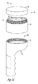
図1Aは、洗浄剤12すなわち化学剤を分配するための例示的な分配システム10を示す。システム10は、洗浄剤12へのユーザの曝露を最小限に抑えるのに好都合に設計されている。これを行うために、システム10は、洗浄剤12を含んだ着脱可能な化学物質容器14を含むことができる。化学物質容器14は、基部18に着脱可能に接続した蓋16を含むことができる。蓋16及び基部18は、例証として図1Aに示されるように、または当該技術分野で一般に知られる任意の他の手段により、ねじ接続することができる。蓋16が基部18から外されるとき、基部18は、その中に含まれる洗浄剤12の効力を保つ(すなわち、あらゆる活性成分の変質を防止する)ために、フィルム(図示せず)を含むことができる。化学物質容器14は、粉末形態、顆粒形態、または錠剤形態の固体化学物質を含むことができる。固体化学物質には塩素が含まれ得るが、本開示は、他の一般に使用される洗浄化学物質、例えばアンモニア、炭酸ナトリウム、水酸化ナトリウム、及びアルカリ性物質、ならびに例えば洗剤、清浄剤、溶剤、脱脂剤などの他の洗浄製品も想定する。別の例示的な実施形態では、分配システム10は、本明細書で詳解される本開示の目的と一致した液体化学物質を使用する。
FIG. 1A illustrates an
化学物質容器14は、ディスペンサ20に操作可能に接続するように構成されている。例証となる図1A及び1Bの実施形態において、化学物質容器14の基部18に関連したねじ筋22は、ディスペンサ20に関連した対応するねじ筋24と接続するように構成されている。連動タブ25(図2)、戻り止めピン、クランプ、締まりばめなどを含む他の接続手段も想起される。化学物質容器14をディスペンサに装着するには、蓋16(及びフィルム)を基部18から外す。ディスペンサ20を反転させ、その後、ねじ筋22、24をねじ係合して、化学物質容器14をディスペンサ20に固定する。こうした装着により、図1Bに例証される例示的なシステム10は、化学物質容器14及びディスペンサ20内に化学剤12を密封可能に含むことになり、ユーザの洗浄剤12への一切の曝露が防止される。
The
別の例示的な実施形態では、洗浄剤12は、ディスペンサ20に注がれるか、または別様に移送される。そのような状況は、ディスペンサ20と嵌合するようなサイズ及び形状の化学物質容器14とは対照的に、化学剤を含む大型のバルク容器を設備が有する場合に生じ得る。洗浄剤12を注ぐこと、すくうこと、または他の同様な手段によって移送することは、洗浄剤12へのユーザの曝露の可能性を増加させ得るが、ディスペンサ20は、好都合なことに、その後の可搬性及び安全性を増加させる。化学剤12がディスペンサに移送された後、ディスペンサ20のねじ筋24または他の接続手段に蓋を固定することができる。この蓋は、化学物質容器14に操作可能に接続されるように構成された蓋16と同じであってもよい。なおも別の例示的な実施形態では、ディスペンサ20は、洗浄剤12を事前に満たしたものとして製造及び/または流通してもよい。
In another exemplary embodiment, cleaning
さらに、薬剤12などの製品との接触の可能性を低減させるために、本明細書に開示されるディスペンサ20によって計測及び/または分配される製品の包装、例えばバルク包装を統合することが想定される。例えば、ディスペンサの一部分をバルク包装に接続してもよく、ディスペンサ20が包装を開けて、薬物12を満たすことを可能にする。ディスペンサ20によって製品が計測及び分配される際、バルク包装が空になるまで、ディスペンサ20に製品が加えられ続ける。これは、例えばディスペンサに薬剤12を物理的に充填する必要性を軽減することによって、取扱者をさらに保護することになる。
Further, it is envisioned to integrate the packaging of the product being metered and/or dispensed by the
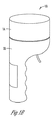
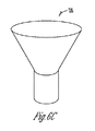
図2を参照すると、例示的なディスペンサ20が示されている。このディスペンサは、化学物質容器14から化学剤12の少なくとも一部分を受けるように構成された収容部分26を含むことができる。収容部分26の形状は、テーパー状であり、かつ/または別様に収容部分26の入口28から収容部分26の出口30に化学剤12をつぎ込むように構成されている。入口28は概して、ねじ筋または他の接続手段の近位にある。例証される図2の実施形態において、収容部分26は部分的に半球状体の形状であり、細長い分配部分32がそこから延びている。本開示は、本開示の目的を逸脱することなく、あらゆる数のテーパー形状を想定する。例えば、収容部分26は、中心から分配部分32が延びている半球状体であってもよい(すなわち、収容部分26及び分配部分32は、上から見ると軸方向に整列している)。収容部分26は、図6A〜6Cに概して例証されるように、角錐形、角錐台形(frustro−pyramidal)、円錐形、または円錐台形であってもよい。
Referring to FIG. 2, an
細長い分配部分32は、入口34及び出口36を有する。分配部分32の入口34は、概して、収容部分26の出口30と関連し、操作可能な連通状態にある。チャネル38は、分配部分32の入口34と出口36とを接続する。出口36は、チャネル38及び/または分配部分32の末端部40に位置付けられている。チャネル38は、化学剤12が重力によってその中を移動するように、概して垂直に配向されていてよい。チャネル38は、収容部分26と選択的に操作可能な連通状態にあってもよく、これは本明細書において詳解される。
The elongated dispensing portion 32 has an
図1A、1B、及び2に例証されるように、分配部分32は、概してハンドルの形状、ならびに/または、手持ち式デバイスとして快適に使用されるような別様のサイズ及び/もしくは形状とすることができる。結果として、図1B及び2にそれぞれ例証される分配システム10及びディスペンサ20は、洗浄剤12の可搬性及び洗浄作業のモジュール性を改善する。
As illustrated in FIGS. 1A, 1B, and 2, the dispensing portion 32 is generally shaped as a handle and/or another size and/or shape for comfortable use as a handheld device. You can As a result, the dispensing
ディスペンサ20、より詳細には分配部分32は、計測チャンバ42(または測定チャンバ)を含むことができる。計測チャンバ42は、ある計測量の洗浄剤12を収容部分26から受けるように構成されている。図2に例証されるように、計測チャンバ42は、概して円柱状であり、ディスペンサ20の分配部分32に選択的に挿入され、かつ/または取り出される(または取り付けられ、かつ/もしくは取り外される)ようなサイズとすることができる。図2、7A、及び7Bに例証されるように、計測チャンバ42は、外表面45から外向きに延びる隆起部分43を有してもよい。隆起部分43は、ディスペンサの分配部分32にしっかりと嵌合するように適合させることができる。計測チャンバ42を分配部分32にしっかりと接続するための手段としては、戻り止めピン、連動タブ、スナップフィット、及び/または締まりばめを挙げることができるが、これらに限定されない。計測チャンバ42は、その中に含まれる洗浄剤12のレベルをユーザが見ることができるように、透明な材料、好ましくはプラスチックまたは他の同様なポリマーから構成されていてもよい。
The
言及したように、洗浄作業は、正確な量の化学洗浄剤を必要とすることが多い。計測チャンバ42は、一貫性のある量の洗浄剤の分配を確実にするために、一定計測量の洗浄剤12を受け、かつ/または分配するように構成されている。異なる洗浄作業は異なる量の化学洗浄剤及び/または他の化学剤を必要とし得るため、計測チャンバ42は、着脱可能であり、異なる一定量の化学剤を保持することのできる異なる計測チャンバに置き換えることができる。言い換えると、ユーザは、用途の要件に基づいて、いくつかの選択的に交換可能な計測チャンバ42のうちの1つを選択することができる。また、計測チャンバ42は、計測及び分配される製品の量を活動中に(on the go)変化させることを可能にするように可変であることが想定される。計測チャンバ42は、分配システム10の効率及びモジュール性を増加させるために容易に取り外され再度取り付けられるように構成されている。例示的な一実施形態において、異なる計測チャンバは、円柱状の形態にある場合、例証として図7A及び7Bに示されるように、より多い量またはより少ない量の洗浄剤12を収容するように、より大きいまたはより小さい内周44を有してもよい。
As mentioned, cleaning operations often require precise amounts of chemical cleaning agents. The
操作中、計測チャンバ42は、収容部分26の出口30及び分配部分32の入口34を通して化学剤12の少なくとも一部分を受けるように構成されている。計測チャンバ42は、チャネル38の一部分を含み得る。計測チャンバ42はまた、化学剤12がディスペンサ20の出口36を通って排出されるように、化学剤12をチャネル38に放出するように構成されている。
During operation,
これを行うために、外部機構46は、ディスペンサ20に操作可能に接続している。例証となる図2の実施形態において、外部機構46は、収容部分26に接続したトリガである。本開示は、代替的な外部機構、例えば、押しボタン、捻りノブ、引きレバーなどを含むがこれらに限定されない作動部材などを想定する。 外部機構46は、ユーザ操作式であってもよい。より具体的に言うと、ユーザ操作式外部機構46は、ユーザインプット(例えば、トリガを引くこと、ボタンを押すこと、ノブを捻ること)を受けて収容部分26及び分配部分32のチャネル38を選択的に接続し、それによって、洗浄剤12が収容部分26の出口30及び分配部分32の入口34を通過する(そして計測チャンバ(42)に入る)ことを可能にするように構成されている。ユーザは、計測チャンバ42に一定計測量の全てを充填するのに十分なインプットを提供してもよいし、あるいは、より少ない計測量の化学剤12を分配するインプットを提供してもよい。言い換えると、計測チャンバ42に移送される計測量は、外部機構46に適用されるユーザインプットに少なくとも部分的に基づき得る。
To do this, the
図3を参照すると、外部機構46は、内部機構48を作動させる。内部機構48は、ユーザインプットを外部機構46に伝達して、ディスペンサ20の内部部品を駆動させるように構成されている。より詳細には、内部機構48は、洗浄剤12がディスペンサ20を通って移動することを可能にするように、収容部分26、計測チャンバ42、及び/またはチャネル38を選択的に接続するように構成されている。例示的な内部機構48には、レバーアーム、ラチェット及び爪、ギヤ、ベルトなどが含まれ得る。別の例示的な実施形態では、内部機構48(及び/または外部機構46)は、電子コントローラ(図示せず)によって遠隔制御することができる。この構成は、分配システム10が手持ち式でないときに特に好適である。そのような実施形態では、内部機構48は、収容部分26、計測チャンバ42、及び/またはチャネル38を選択的に接続するように、電気モータ、電磁ソレノイドなどであってもよい。
Referring to FIG. 3, the
より具体的に言うと、内部機構48は、分配部分32に関連した入口ゲート50及び出口ゲート52を選択的に開放及び閉鎖するように構成されている。図3及び5を参照すると、入口ゲート50は、収容部分の出口30と測定チャンバ42の入口54との間に配設されている。別の例示的な実施形態では、入口ゲート50は、チャネル38内で、分配部分32の入口36と測定チャンバ42の入口54との間に配設されていてもよい。本開示は、入口ゲート50が洗浄剤12の測定チャンバ42内への移送を選択的に調節する限り、収容部分の出口30、分配部分32の入口36、及び/または測定チャンバ42の入口54に対する入口ゲート50のあらゆる位置を想定する。同様に、出口ゲート52は、測定チャンバ42の出口56の近位に配設されている。出口ゲート52は、チャネル38内またはその近位に位置付けられ、測定チャンバ42からディスペンサ20の出口36への洗浄剤12の移送を調節するように構成されていてもよい。
More specifically, the
例証される図3及び5の例示的な実施形態において、入口ゲート50は、側面から見ると板状の構造体とすることができる。入口ゲート50及び/または出口ゲート54には、回転ディスク、スライドゲート、及び/またはトラップドアが含まれ得る。
In the illustrated exemplary embodiment of FIGS. 3 and 5, the inlet gate 50 can be a plate-like structure when viewed from the side. The entrance gate 50 and/or the
回転ディスク60を使用した入口ゲート50及び/または出口ゲート52の例示的な一実施形態が、図3及び4に例証されている。ディスク60は、概して平坦であり、ディスク60の中心を通って延びる輪軸62に接続していてもよい。駆動ギヤ64が輪軸62及び/またはディスク60に接続していてもよい。駆動ギヤ64は、内部機構48に操作可能に接続するように構成されている。駆動ギヤ64が図4に例証されているが、本開示は、ユーザインプットに際しディスク60を回転させるための他の手段は、ラチェット及び爪、ならびに他の種類の伝動装置を含むがこれらに限定されない。電子コントローラを使用する実施形態では、ディスク60は、電気モータを使用して回転させることができる。
An exemplary embodiment of the entrance gate 50 and/or the
ディスク60内には、穴などの開口部66が偏心して位置付けられている。入口ゲート50及び出口ゲート52の各々の開口部66は、それぞれ、洗浄剤12が計測チャンバ42に入ったり、そこから出たりすることを可能にするように構成されている。開放位置において、開口部66は、チャネル38、ならびに計測チャンバ42の入口54及び出口56と軸方向に整列している。閉鎖位置では、開口部66は、開口部66が細長い分配部分32のハンドル位置67内に来るように、概して180度回転している。この閉鎖位置において、図4に例証されるディスク60のバリア部分70が、洗浄剤12が計測チャンバ42に入ること、あるいはそこから出ることを防止する。図3に例証される構成では、入口ゲート50は開放位置にあり、出口ゲート52は閉鎖位置にある。
An opening 66 such as a hole is eccentrically positioned in the
例示的な一実施形態において、図3に例証される構成は、デフォルト構成であり得る。洗浄剤12は、計測チャンバ42が満たされるまで計測チャンバ42に入るが、洗浄剤12は排出されない。ユーザが計測チャンバ42から一定計測量を分配することを望むとき、ユーザは外部機構46を係合させる(例えば、トリガを引く)。外部機構46は内部機構48を作動させ、内部機構48は、輪軸62及び/またはディスク60に操作可能に接続した駆動ギヤ64を駆動する。入口ゲート50が開放位置から閉鎖位置へと回転し、それにより、さらなる洗浄剤が計測チャンバ42に入ることを防止する。同時に閉鎖ゲート60が閉鎖位置から開放位置へと回転して、一定計測量がチャネル38の残部及びディスペンサの出口36を通って排出されることを可能にすることができる。例示的な一実施形態において、入口ゲート50の下面に関連した輪軸62は、図3に例証されるように、出口ゲート52の上面にも関連している。したがって、単一のユーザインプットが、入口ゲート50及び出口ゲート52を作動させることができる。
In one exemplary embodiment, the configuration illustrated in Figure 3 may be the default configuration. The
少なくとも1つのねじりばね69が、入口ゲート50のディスク60及び/または出口ゲート52のディスク60に操作可能に接続していてもよい。開放位置において、ねじりばね69は、非圧縮状態にあり得る。外部機構46へのユーザインプットによりディスク(複数可)60が回転すると、ねじりばね69が縮み、その結果、ユーザが外部機構46を解放すると、入口ゲート50及び出口ゲート52がデフォルト位置に戻る。
At least one
別の例示的な実施形態では、デフォルト構成は、閉鎖位置にある入口ゲート50、及び開放位置にある出口ゲート52を含む。ユーザが計測チャンバ42から計測量を分配することを望むとき、ユーザは外部機構46を係合させる。外部機構46は内部機構48を作動させ、内部機構48は、輪軸62及び/またはディスク60に操作可能に接続した駆動ギヤ64を駆動する。入口ゲート50は閉鎖位置から開放位置へと回転し、閉鎖ゲート60は同時に開放位置から閉鎖位置へと回転することができる。この操作は上記に詳解された例示的な実施形態と同様であるが、デフォルト位置を反転させることにより、ユーザが一定測定量未満の計測を行うことが可能になる。具体的に言うと、ユーザが計測チャンバ42の容量の2分の1を測定することを所望する場合、ユーザは、一定計測量の洗浄剤12が計測チャンバ42に入る前に外部機構46を解放することができる。ねじりばね69が解放され、それにより、入口ゲート50の閉鎖及び出口ゲート52の開放が同時に起こる。本開示は、デフォルト構成が、ディスペンサ20を操作する前にユーザによって選択的に調節可能であり得ることを想定する。
In another exemplary embodiment, the default configuration includes an entrance gate 50 in a closed position and an
スライドゲート68を使用した入口ゲート50及び/または出口ゲート52の例示的な一実施形態が、図5に例証されている。スライドゲート68は、側面から見ると平坦な板状の構造体とすることができる。スライドゲート68は、内部機構48に操作可能に接続することができる。例証される図5の実施形態において、内部機構48は、ヒンジ70でスライドゲート68に接続した板状の構造体である。内部機構48は、外部機構46へのユーザインプットの適用及び/または解除に際し、スライドゲート68に横方向の力を提供するように構成されている。例示的な一実施形態において、外部機構46は、枢動可能にピボット72に接続しており、入口ゲート50及び出口ゲート52に関連した内部機構48は、外部機構に接続している。
An exemplary embodiment of the entrance gate 50 and/or the
図3に例証され上記に詳解された例示的な実施形態と同様に、スライドゲートを使用する実施形態は、2つ以上のデフォルト構成を有することができる。例証される図5の実施形態において、入口ゲート50のスライドゲート68は閉鎖位置にあり、出口ゲート52のスライドゲート68は開放位置にある。ユーザインプットを適用すると、外部機構46がピボット72を中心として枢動する。横方向の力が加えられて、入口ゲート50を開放位置に移動させ(すなわち、「引き」)、同時に出口ゲート52を閉鎖位置に移動させる(すなわち、「押す」)。洗浄剤12が、重力から、収容部分の出口30、細長い分配部分32の入口34、及び計測チャンバ42の入口54を通って降下する。ある計測量、すなわち計測チャンバ42に関連した一定計測量が計測チャンバ42に含まれているとき、ユーザは、ユーザインプットを解除することができる。外部機構46と分配部分32のハンドル部分67とに操作可能に接続した弾性部材74は、外部機構46をデフォルト構成に戻させる。入口ゲート50及び出口ゲート52も同様にそれらのデフォルト位置に戻る。本開示は、本開示の目的を逸脱することなく、弾性部材74が、デバイスをデフォルト構成に戻すように、内部機構48または任意の他の部品に接続していてもよいことを想定する。
Similar to the exemplary embodiment illustrated in FIG. 3 and detailed above, embodiments using a sliding gate can have more than one default configuration. In the illustrated embodiment of FIG. 5, the sliding gate 68 of the inlet gate 50 is in the closed position and the sliding gate 68 of the
別の例示的な実施形態では、デフォルト構成は、開放位置にある入口ゲート50、及び閉鎖位置にある出口ゲート52を含む。例証される図3の例示的な実施形態と同様に、洗浄剤12は、計測チャンバ42が満たされるまで計測チャンバ42に入るが、排出されない。ユーザが計測チャンバ42から一定計測量を分配することを望むとき、ユーザは外部機構46を係合させ、これが内部機構48を作動させる。入口ゲート50のスライドゲート68が開放位置から閉鎖位置へと移動し、それにより、さらなる洗浄剤が計測チャンバ42に入ることを防止する。同時に出口ゲート52のスライドゲート68が閉鎖位置から開放位置へと移動して、一定計測量がチャネル38の残部及びディスペンサの出口36を通って排出されることを可能にする。本開示は、デフォルト構成が、ディスペンサ20を操作する前にユーザによって選択的に調節可能であり得ることを想定する。
In another exemplary embodiment, the default configuration includes inlet gate 50 in the open position and
別の例示的な実施形態では、入口ゲート50及び/または出口ゲート52は、ラッチ、ばね、及び他の機構によって作動するトラップドアとすることができる。ユーザから外部機構46にインプットがなされると、ラッチが外れ、それによってトラップドアの開放を可能にすることができる。洗浄剤12が計測チャンバ42に入る。ユーザが解放すると(または第2のユーザインプットが適用されると)、出口ゲート52に関連したトラップドアに関連したラッチが外れ、それによって洗浄剤がディスペンサ20から出ることが可能になる。ユーザインプットの適用及び/または解除により、入口ゲートならびに/または出口ゲート52を開放及び/もしくは閉鎖するように、1つ以上のばねが、内部機構(複数可)48及びトラップドアに操作可能に接続していてもよい。
In another exemplary embodiment, the entrance gate 50 and/or the
なおも別の例示的な実施形態において、外部機構46は、二段動作トリガとすることができる。二段動作トリガは、関連した2回の「トリガ引き動作」を2つの別々の動作で区切るように構成された内部機構48から構成され得る。具体的に言うと、二段動作トリガを用いると、第1のトリガ引き動作が、入口ゲート50を開放し出口ゲート52を閉鎖させることができ、第2のトリガ引き動作が、入口ゲート50を閉鎖させ出口ゲート52を開放することができる。さらに、二段動作トリガ、ならびにますます複雑な外部機構46及び内部機構48を用いると、デフォルト構成は、両方とも閉鎖位置にある入口ゲート50及び出口ゲート52を含むことができ、ここで、入口ゲート50または出口ゲート52は、選択的かつ独立的に開放可能及び/または閉鎖可能である。
In yet another exemplary embodiment, the
なおもさらに別の例示的な実施形態では、電子コントローラが、内部機構(複数可)48を介して入口ゲート50及び出口ゲート52を操作可能に制御する。本開示は、これを行う当該技術分野で一般に知られる任意の手段、特に電子スイッチ及びソレノイドを想定する。電子コントローラ及び他の電子部品は、ディスペンサ20のハンドル部分67内に配設されたバッテリ(図示せず)または他の動力源によって給電され得る。
In still yet another exemplary embodiment, an electronic controller operably controls the inlet gate 50 and the
本開示は、本明細書に記載される特定の実施形態に限定されるものではない。特に、本開示は、本開示の実施形態が、清浄剤及び/または他の洗浄製品を必要とする洗浄プロセスにおいて粉末、顆粒、及び他の固体状の化学物質を分配するためのシステム、デバイス、ならびに方法に適用され得る方法の種類における、多数の変形形態を想定する。前述の説明は、例証及び説明を目的として提示したものである。これは、網羅的なリストであることを意図するものでも、開示内容のいずれかを開示された形態そのものに限定することを意図するものでもない。考察される他の代替案または例示的な態様が本開示に含まれることが想定される。この説明は、本開示の実施形態、プロセス、または方法の例に過ぎない。意図される本開示の趣旨及び範囲に含まれる、あらゆる他の変更、代用、及び/または追加が行われ得ることが理解される。前述の内容に関しては、少なくとも意図される事項の全てが本開示によって達成されることが分かる。 This disclosure is not limited to the particular embodiments described herein. In particular, the present disclosure provides systems, devices, and devices for dispensing powders, granules, and other solid state chemicals in cleaning processes that require detergents and/or other cleaning products. And numerous variations in the types of methods that may be applied to the method. The preceding description has been presented for purposes of illustration and description. It is not intended to be an exhaustive list, nor is it intended to limit any of the disclosure to the form disclosed. It is envisioned that other alternatives or exemplary aspects discussed are included in this disclosure. This description is merely an example of embodiments, processes, or methods of the disclosure. It is understood that any other changes, substitutions, and/or additions may be made that fall within the spirit and scope of the present disclosure as intended. With regard to the foregoing, it will be seen that at least all of the intended matters are achieved by the present disclosure.
先の詳細な説明は、本開示を実践するための少数の実施形態に関するものであり、範囲を限定することを意図するものではない。続く「特許請求の範囲」は、本開示のいくつかの実施形態をより詳細に示すものである。
The above detailed description is directed to a few embodiments for practicing the present disclosure and is not intended to be limiting in scope. The following “claims” set forth some of the embodiments of the disclosure in more detail.
Claims (19)
前記システムが、前記工業用洗浄剤を収容する容器と、ディスペンサとを備え、
前記ディスペンサが、
(a)前記容器に収容された前記工業用洗浄剤の少なくとも一部を受けるように構成された収容部分と、
(b)前記収容部分と選択的に操作可能な接続状態にあるチャネルを有する細長い分配部分と、
(c)着脱可能な計測チャンバであって、出口と、当該チャンバの外表面から外向きに延びて前記細長い分配部分に嵌合するための隆起部分とを有する着脱可能な計測チャンバと、
を含み、
前記容器と前記ディスペンサの前記収容部分は、互いにねじ接続可能で着脱自在に構成されている、システム。 A handheld dispensing system for dispensing industrial cleaning agents,
The system comprises a container containing the industrial cleaning agent, and a dispenser,
The dispenser is
(A) a storage portion configured to receive at least a part of the industrial cleaning agent stored in the container,
(B) an elongated dispensing portion having a channel in selectively operable connection with the receiving portion;
(C) a removable measurement chamber, the removable measurement chamber having an outlet and a raised portion extending outwardly from an outer surface of the chamber to fit the elongated dispensing portion;
Including,
The system, wherein the container and the receiving portion of the dispenser are configured to be screwed to each other and detachably configured.
一定計測量の前記工業用洗浄剤を前記収容部分から受けるように構成され、かつ前記一定計測量を前記チャネルに分配するように構成され、前記細長い分配部分に関連している、請求項1に記載のシステム。 The removable measurement chamber is
The method of claim 1 configured to receive a metered amount of the industrial cleaning agent from the receiving portion and to distribute the metered amount to the channel, and associated with the elongated dispensing portion. The described system.
前記選択的に操作可能な接続が、前記工業用洗浄剤が前記収容部分から着脱可能な前記計測チャンバに移送されることを可能にする、請求項2に記載のシステム。 Further comprising a user-actuable mechanism configured to receive user input and selectively connect the receiving portion and the elongated dispensing portion,
The system of claim 2, wherein the selectively operable connection allows the industrial cleaning agent to be transferred from the receiving portion to the removable measurement chamber.
前記デバイスが、前記工業用洗浄剤を収容する容器と、ディスペンサとを備え、
前記ディスペンサが、
入口及び出口を有する収容部分と、
前記収容部分の前記出口と操作可能な連通状態にある細長い分配部分と、
前記細長い分配部分に関連した着脱可能な測定チャンバであって、入口、当該チャンバの外表面から外向きに延びて前記細長い分配部分に嵌合するための隆起部分、及び出口を有する着脱可能な測定チャンバと、
前記収容部分の前記出口と前記着脱可能な測定チャンバの前記入口との間に配設された入口ゲートと、
前記着脱可能な測定チャンバの前記出口の近位に配設された出口ゲートと、
を備え、
前記入口ゲート及び前記出口ゲートが、前記着脱可能な測定チャンバ内の洗浄剤の量を選択的に計測するために選択的に開放及び閉鎖されるように適合され、
前記容器は、前記ディスペンサの前記収容部分の入口に対して、ねじ接続可能で着脱自在に構成されている、デバイス。 A device for dispensing industrial cleaning agents, comprising:
The device comprises a container containing the industrial cleaning agent, and a dispenser,
The dispenser is
A storage part having an inlet and an outlet,
An elongated dispensing portion in operable communication with the outlet of the receiving portion;
A removable measurement chamber associated with the elongated dispensing portion, the removable measuring chamber having an inlet, a raised portion extending outwardly from an outer surface of the chamber to fit the elongated dispensing portion, and an outlet. A chamber,
An inlet gate disposed between the outlet of the receiving portion and the inlet of the removable measurement chamber,
An outlet gate disposed proximal to the outlet of the removable measurement chamber,
Equipped with
The inlet gate and the outlet gate are adapted to be selectively opened and closed to selectively measure the amount of cleaning agent in the removable measurement chamber,
The device, wherein the container is configured to be attachable/detachable by screw connection to the inlet of the accommodation portion of the dispenser.
前記化学剤を分配デバイスの収容部分に充填するステップであって、前記収容部分が前記化学剤を入口ゲートに向けてつぎ込む、充填するステップと、
出口ゲートを開放し前記入口ゲートを閉鎖するための機構を作動させるステップと、
前記入口ゲートが開放しており前記出口ゲートが閉鎖しているときに、ある計測量の前記化学剤を着脱可能な測定チャンバ内に移送するステップと、
前記機構を停止させて前記出口ゲートを閉鎖し前記入口ゲートを開放するステップと、
前記出口ゲートが開放しており前記入口ゲートが閉鎖しているときに、前記分配デバイスから前記化学剤を分配するステップと、
を含み、
前記着脱可能な測定チャンバは、当該チャンバの外表面から外向きに延びる隆起部分を介して細長い分配部分に嵌合され、
前記化学剤を前記収容部分に充填するステップにおいて、前記化学剤を含んだ着脱可能な化学物質容器を前記収容部分にねじ接続する、方法。 A method for dispensing a chemical agent, comprising:
Filling the receiving portion of the dispensing device with the chemical agent, the receiving portion pouring the chemical agent toward the inlet gate, filling;
Activating a mechanism for opening the exit gate and closing the entrance gate;
Transferring a measured amount of the chemical agent into a removable measurement chamber when the inlet gate is open and the outlet gate is closed;
Stopping the mechanism to close the exit gate and open the entrance gate;
Dispensing the chemical agent from the dispensing device when the exit gate is open and the entrance gate is closed;
Including,
The removable measurement chamber is fitted to the elongated dispensing portion via a raised portion extending outwardly from the outer surface of the chamber,
The method of filling the containing portion with the chemical agent by screwing a removable chemical container containing the chemical agent to the containing portion.
The industrial cleaning agent is a liquid, according to any one of claims 1 to 5 systems.
Applications Claiming Priority (3)
| Application Number | Priority Date | Filing Date | Title |
|---|---|---|---|
| US201562206390P | 2015-08-18 | 2015-08-18 | |
| US62/206,390 | 2015-08-18 | ||
| PCT/US2016/047502 WO2017031284A1 (en) | 2015-08-18 | 2016-08-18 | Dispensing device and system for solid chemical cleaning agents |
Publications (2)
| Publication Number | Publication Date |
|---|---|
| JP2018527566A JP2018527566A (en) | 2018-09-20 |
| JP6701323B2 true JP6701323B2 (en) | 2020-05-27 |
Family
ID=58051824
Family Applications (1)
| Application Number | Title | Priority Date | Filing Date |
|---|---|---|---|
| JP2018508723A Active JP6701323B2 (en) | 2015-08-18 | 2016-08-18 | Dispensing device and system for solid chemical cleaning agents |
Country Status (15)
| Country | Link |
|---|---|
| US (1) | US10724885B2 (en) |
| EP (1) | EP3338065B1 (en) |
| JP (1) | JP6701323B2 (en) |
| KR (1) | KR102026749B1 (en) |
| CN (1) | CN108351245B (en) |
| AU (1) | AU2016308258B2 (en) |
| BR (1) | BR112018002937B1 (en) |
| HK (1) | HK1252086A1 (en) |
| MX (1) | MX2018002039A (en) |
| MY (1) | MY193632A (en) |
| NZ (1) | NZ739716A (en) |
| PH (1) | PH12018500364A1 (en) |
| SA (1) | SA518390943B1 (en) |
| WO (1) | WO2017031284A1 (en) |
| ZA (1) | ZA201800908B (en) |
Families Citing this family (8)
| Publication number | Priority date | Publication date | Assignee | Title |
|---|---|---|---|---|
| US10549245B2 (en) | 2014-08-05 | 2020-02-04 | Ecolab Usa Inc. | Apparatus and method for dispensing solutions from solid products |
| KR101896075B1 (en) * | 2017-06-07 | 2018-09-07 | 김용태 | A powder dispenser |
| SG11202007457PA (en) | 2018-02-05 | 2020-09-29 | Ecolab Usa Inc | Packaging and docking system for non-contact chemical dispensing |
| EP3752280A1 (en) | 2018-02-13 | 2020-12-23 | Ecolab Usa Inc. | Portable solid product dispenser and use thereof, and method of dispensing a solution of a fluid and a solid product |
| US10870091B2 (en) | 2018-02-13 | 2020-12-22 | Ecolab Usa Inc. | System for dissolving solid chemicals and generating liquid solutions |
| WO2020163470A1 (en) | 2019-02-05 | 2020-08-13 | Ecolab Usa Inc. | Packaging and docking system for non-contact chemical dispensing |
| BR112021023963A2 (en) | 2019-05-30 | 2022-01-25 | Ecolab Usa Inc | Separator basket system, chemical dispensing docking station, and chemical dispensing method |
| DE102022003855A1 (en) * | 2022-10-13 | 2024-04-18 | Aaron Holzhäuer | Manual dosing device |
Family Cites Families (41)
| Publication number | Priority date | Publication date | Assignee | Title |
|---|---|---|---|---|
| US534082A (en) * | 1895-02-12 | Measuring apparatus | ||
| USRE22083E (en) * | 1942-04-28 | Gaseous and vapor electric | ||
| US1724751A (en) * | 1927-11-09 | 1929-08-13 | Herbert C Cushing | Coffee meter |
| US3080095A (en) * | 1961-12-27 | 1963-03-05 | Woroble Joseph | Container piercing and powder measuring dispenser |
| US3204833A (en) | 1964-02-18 | 1965-09-07 | Weitzner Adolph | Never open container with a dispensing and measuring device |
| JPS5215820Y2 (en) * | 1972-10-31 | 1977-04-09 | ||
| US3850347A (en) | 1973-06-14 | 1974-11-26 | Hill G | Combination dispenser package with portion measuring means for dispensing controlled amounts of fluent materials |
| CA1027526A (en) | 1975-05-02 | 1978-03-07 | Charles W. Maves | Manually operated controlled volume dispenser for free-flowing product |
| JPS5233360U (en) * | 1975-08-30 | 1977-03-09 | ||
| JPS5337554U (en) * | 1976-09-06 | 1978-04-01 | ||
| JPS5728109Y2 (en) * | 1976-09-16 | 1982-06-18 | ||
| JPS53105764U (en) * | 1977-01-31 | 1978-08-25 | ||
| USRE33083E (en) | 1984-02-10 | 1989-10-10 | Controlled dispensing apparatus | |
| DE3438677A1 (en) | 1984-10-22 | 1986-04-24 | Ursula 7790 Meßkirch Trautmann | Closure lid with apportioning device for packages and containers of powdery to granular substances |
| US4708265A (en) * | 1986-07-23 | 1987-11-24 | Bopst Iii John H | System for automatic measuring and dispensing of grain and powder food products |
| JPH03102219A (en) * | 1989-09-14 | 1991-04-26 | Futaba Denki Kogyo Kk | Apparatus for packing measured quantity of meat |
| JP3091094B2 (en) * | 1993-12-28 | 2000-09-25 | ユニチカ株式会社 | Reagent for direct bilirubin measurement |
| US5685461A (en) * | 1995-05-23 | 1997-11-11 | Mitchell; Terry | Apparatus for dispensing a uniform volume of granular material |
| JP3024121U (en) * | 1995-10-26 | 1996-05-17 | 清子 斎藤 | Milk powder meter |
| US5746355A (en) * | 1996-03-15 | 1998-05-05 | Cargill, Incorporated | Dispenser for pulverulent material |
| US5758803A (en) * | 1996-08-20 | 1998-06-02 | Chin-Hai Liao | Milk powder dispenser |
| JP3061959U (en) * | 1999-03-08 | 1999-09-28 | 株式会社ニユートーキヨー | Dispenser for tea leaves |
| US6244470B1 (en) | 1999-12-21 | 2001-06-12 | Sandria C. Harley-Wilmot | Measured quantity liquid dispenser |
| US20030146246A1 (en) * | 2002-02-07 | 2003-08-07 | Arsenault Cathleen M. | Dosing device |
| US7497359B2 (en) | 2002-02-07 | 2009-03-03 | 3M Innovative Properties Company | Dosing device |
| CN100528255C (en) * | 2002-02-22 | 2009-08-19 | Gw药品有限公司 | Dose dispensing system and apparatus |
| US7032787B2 (en) | 2002-05-01 | 2006-04-25 | William M. Sherk, Jr. | Integrated dispenser |
| JP3091094U (en) | 2002-06-21 | 2003-01-17 | 魏 煥圭 | Quantitative removal of powder and granular material storage cans |
| US7815072B2 (en) * | 2004-05-06 | 2010-10-19 | Diversey, Inc. | Metering and dispensing closure |
| US6929159B1 (en) * | 2004-11-24 | 2005-08-16 | Voy Haig | Quantitative measuring dispenser |
| US20080099509A1 (en) * | 2006-10-31 | 2008-05-01 | Charles Mountjoy | Coffee ground dispenser |
| IT1391186B1 (en) * | 2008-08-01 | 2011-11-18 | Eltek Spa | DISPENSER OF WASHING AGENTS FOR A WASHING MACHINE |
| US8002153B2 (en) * | 2008-09-10 | 2011-08-23 | Lowther Kristine A | Powder food dispenser |
| WO2010033023A2 (en) * | 2008-09-17 | 2010-03-25 | Sara Lee/De N.V. | System for preparing coffee beverage |
| US8905272B2 (en) * | 2009-11-05 | 2014-12-09 | Birost Llc | Sealed dispenser for metered fluent materials |
| KR101179698B1 (en) | 2010-02-19 | 2012-09-04 | 차종헌 | Apparatus for Dispenser |
| US8439231B2 (en) * | 2011-04-21 | 2013-05-14 | Easy Go Dispenser, Llc | Powder measuring and dispensing apparatus |
| DE102011082420B4 (en) | 2011-09-09 | 2021-02-04 | Aptar Radolfzell Gmbh | Liquid dispenser and discharge head for a liquid dispenser |
| JP6037778B2 (en) | 2012-10-31 | 2016-12-07 | 株式会社吉野工業所 | Weighing cap |
| US9580227B2 (en) * | 2014-11-04 | 2017-02-28 | Zak Wood | Baby bottle |
| US20160298993A1 (en) * | 2015-04-07 | 2016-10-13 | Aaron Lee Bernard | Measuring and dispensing devices and methods for measuring and dispensing materials |
-
2016
- 2016-08-18 US US15/240,345 patent/US10724885B2/en active Active
- 2016-08-18 AU AU2016308258A patent/AU2016308258B2/en active Active
- 2016-08-18 MX MX2018002039A patent/MX2018002039A/en unknown
- 2016-08-18 JP JP2018508723A patent/JP6701323B2/en active Active
- 2016-08-18 CN CN201680048620.XA patent/CN108351245B/en active Active
- 2016-08-18 BR BR112018002937-8A patent/BR112018002937B1/en active IP Right Grant
- 2016-08-18 NZ NZ739716A patent/NZ739716A/en unknown
- 2016-08-18 WO PCT/US2016/047502 patent/WO2017031284A1/en active Application Filing
- 2016-08-18 KR KR1020187004877A patent/KR102026749B1/en active IP Right Grant
- 2016-08-18 MY MYPI2018000220A patent/MY193632A/en unknown
- 2016-08-18 EP EP16837814.9A patent/EP3338065B1/en active Active
-
2018
- 2018-02-12 ZA ZA2018/00908A patent/ZA201800908B/en unknown
- 2018-02-15 PH PH12018500364A patent/PH12018500364A1/en unknown
- 2018-02-18 SA SA518390943A patent/SA518390943B1/en unknown
- 2018-09-05 HK HK18111396.7A patent/HK1252086A1/en unknown
Also Published As
| Publication number | Publication date |
|---|---|
| CN108351245B (en) | 2020-12-08 |
| PH12018500364B1 (en) | 2018-08-29 |
| EP3338065B1 (en) | 2024-03-13 |
| EP3338065A1 (en) | 2018-06-27 |
| EP3338065A4 (en) | 2019-08-07 |
| BR112018002937B1 (en) | 2022-03-15 |
| MY193632A (en) | 2022-10-20 |
| HK1252086A1 (en) | 2019-05-17 |
| KR20180032607A (en) | 2018-03-30 |
| BR112018002937A2 (en) | 2018-10-02 |
| US10724885B2 (en) | 2020-07-28 |
| SA518390943B1 (en) | 2021-08-30 |
| NZ739716A (en) | 2019-06-28 |
| AU2016308258A1 (en) | 2018-03-01 |
| MX2018002039A (en) | 2018-04-13 |
| CN108351245A (en) | 2018-07-31 |
| PH12018500364A1 (en) | 2018-08-29 |
| KR102026749B1 (en) | 2019-09-30 |
| WO2017031284A1 (en) | 2017-02-23 |
| US20170052051A1 (en) | 2017-02-23 |
| ZA201800908B (en) | 2018-12-19 |
| JP2018527566A (en) | 2018-09-20 |
| AU2016308258B2 (en) | 2019-04-11 |
Similar Documents
| Publication | Publication Date | Title |
|---|---|---|
| JP6701323B2 (en) | Dispensing device and system for solid chemical cleaning agents | |
| EP2139374B1 (en) | Mobile dosing system for the release of preparations capable of flow or dispersion | |
| JP5313966B2 (en) | Metering device | |
| US20050045652A1 (en) | Distributable container and system and method using distributable container | |
| JP2002191289A (en) | Drink dispensing machine | |
| JP6396103B2 (en) | Hand-held quantitative dispensing device for powdered or pasty quantitative materials | |
| KR20180097424A (en) | Combined storage, dosing and mixing device | |
| WO2005114114A1 (en) | Dosing device | |
| CN102458212A (en) | Detergent dispensing device | |
| WO2009032633A1 (en) | Valve assembly for powder dispenser | |
| EP1493375A1 (en) | Multidose detergent dispenser for dishwasher | |
| CA2523750C (en) | System for dispensing an active ingredient using a dispensable tablet, dispensable tablet and container for holding such dispensable tablets | |
| EP2765114A1 (en) | Dosage valve for transferring liquids with increased practicality of use | |
| US20050258195A1 (en) | Dispenser for solid particulate products | |
| US6374875B1 (en) | Device for metering a granular material | |
| KR20150106289A (en) | Discharge device of required dose and packing container having the discharge device | |
| JP2704177B2 (en) | Fluid material dispenser | |
| KR101318767B1 (en) | Powder feeding apparatus using measuring spoon sliding horizontally | |
| EP2998165B1 (en) | Dosage dispenser for a waste holding tank having a pour spout | |
| RU2411169C1 (en) | Package | |
| JP2000241224A (en) | Quantitative and desired amount liquid metering and discharging container and method for metering and discharging desired amount of liquid | |
| ITMI992464A1 (en) | DOSER FOR CONTAINERS OF GRANULAR AND INCONERENT POWDER PRODUCTS IN GENERAL |
Legal Events
| Date | Code | Title | Description |
|---|---|---|---|
| A621 | Written request for application examination |
Free format text: JAPANESE INTERMEDIATE CODE: A621 Effective date: 20180306 |
|
| A131 | Notification of reasons for refusal |
Free format text: JAPANESE INTERMEDIATE CODE: A131 Effective date: 20181030 |
|
| A521 | Request for written amendment filed |
Free format text: JAPANESE INTERMEDIATE CODE: A523 Effective date: 20190130 |
|
| A131 | Notification of reasons for refusal |
Free format text: JAPANESE INTERMEDIATE CODE: A131 Effective date: 20190521 |
|
| A521 | Request for written amendment filed |
Free format text: JAPANESE INTERMEDIATE CODE: A523 Effective date: 20190820 |
|
| A131 | Notification of reasons for refusal |
Free format text: JAPANESE INTERMEDIATE CODE: A131 Effective date: 20191217 |
|
| A521 | Request for written amendment filed |
Free format text: JAPANESE INTERMEDIATE CODE: A523 Effective date: 20200316 |
|
| TRDD | Decision of grant or rejection written | ||
| A01 | Written decision to grant a patent or to grant a registration (utility model) |
Free format text: JAPANESE INTERMEDIATE CODE: A01 Effective date: 20200407 |
|
| A61 | First payment of annual fees (during grant procedure) |
Free format text: JAPANESE INTERMEDIATE CODE: A61 Effective date: 20200501 |
|
| R150 | Certificate of patent or registration of utility model |
Ref document number: 6701323 Country of ref document: JP Free format text: JAPANESE INTERMEDIATE CODE: R150 |
|
| R250 | Receipt of annual fees |
Free format text: JAPANESE INTERMEDIATE CODE: R250 |