JP6700635B2 - Food coating equipment - Google Patents
Food coating equipment Download PDFInfo
- Publication number
- JP6700635B2 JP6700635B2 JP2018233244A JP2018233244A JP6700635B2 JP 6700635 B2 JP6700635 B2 JP 6700635B2 JP 2018233244 A JP2018233244 A JP 2018233244A JP 2018233244 A JP2018233244 A JP 2018233244A JP 6700635 B2 JP6700635 B2 JP 6700635B2
- Authority
- JP
- Japan
- Prior art keywords
- liquid
- belt conveyor
- belt
- downstream
- row
- Prior art date
- Legal status (The legal status is an assumption and is not a legal conclusion. Google has not performed a legal analysis and makes no representation as to the accuracy of the status listed.)
- Active
Links
Images


Landscapes
- Formation And Processing Of Food Products (AREA)
- Structure Of Belt Conveyors (AREA)
- Attitude Control For Articles On Conveyors (AREA)
Description
本発明は、食品用コーティング装置に関するものである。 The present invention relates to a food coating device.
対象物を液体でコーティングする食品用コーティング装置がある。 There is a food coating device for coating an object with a liquid.
食品用コーティング装置の例として、ソース等の粘度が比較的高い液体で対象物をコーティングする装置がある。また、対象物をフライ用に加工する食品加工装置は、バッタリング装置とパン粉等の粉体付着装置とを有する。対象物を天ぷら用に加工する食品加工装置も、同様にバッタリング装置を有する。このバッタリング装置も食品用コーティング装置の例に該当する。 An example of a food coating device is a device that coats an object with a liquid having a relatively high viscosity, such as a sauce. A food processing device that processes an object for frying has a buttering device and a powder adhering device such as bread crumbs. A food processing device for processing an object for tempura also has a buttering device. This buttering device also corresponds to an example of a food coating device.
このような食品用コーティング装置として、特許文献1に示すものがある。食品用コーティング装置の一例である特許文献1のバッタリング装置は、対象物を搬送するコンベアと、コンベアの上方に設けられた液体散布機構とを有する。 As such a food coating device, there is one shown in Patent Document 1. The buttering device of Patent Document 1 that is an example of a food coating device includes a conveyor that conveys an object, and a liquid spraying mechanism that is provided above the conveyor.
特許文献1に代表されるような食品用コーティング装置は以下の課題がある。 The food coating device represented by Patent Document 1 has the following problems.
次工程のコンベアへの落下の衝撃が大きいと、対象物の破損やコーティングの不均一化が生じるという課題がある。また、液体の粘度が高いため、次工程のコンベアへの落下によって、コーティングされた対象物が曲がってしまうという課題もある。 If the impact of the drop on the conveyor in the next step is large, there is a problem that the object is damaged and the coating becomes uneven. Further, since the viscosity of the liquid is high, there is a problem that the coated object is bent when dropped on the conveyor in the next step.
上記の課題を解決しなければ、製品価値の低下又は製造効率が低下するという問題がある。 If the above problems are not solved, there is a problem that the product value is lowered or the manufacturing efficiency is lowered.
そこで、上記点より本発明は、加工した対象物の品質の安定性が向上するとともに、製造効率が向上する食品用コーティング装置を提供することを目的とする。 Therefore, from the above point of view, it is an object of the present invention to provide a food coating apparatus in which the quality stability of a processed object is improved and the production efficiency is improved.
上記課題を解決するため、請求項1の食品用コーティング装置は、対象物を搬送するベルトコンベアと、このベルトコンベアの上方に設けられており、ベルトコンベアで搬送される対象物に向かって液体を流下させる液体流下手段とを有し、ベルトコンベアには、対象物が搬送方向に対して直角方向に対象物の一端から他端までが伸びるように載置され、ベルトコンベアの下流の端から対象物が次工程の装置へと落下するようになっており、ベルトコンベアの下流の端の近傍に、対象物の他端の落下を遅らせる落下遅延手段をさらに有する。 In order to solve the above problems, the food coating apparatus according to claim 1 is provided with a belt conveyor that conveys an object, and is provided above the belt conveyor, and the liquid is directed toward the object conveyed by the belt conveyor. and a liquid flow down means for a stream of the belt conveyor, the object is placed as from one end of the object to the other end extending in a direction perpendicular to the conveying direction, the subject from the downstream end of the conveyor belt The object is designed to drop to the apparatus of the next step, and further has a drop delay means for delaying the fall of the other end of the object near the downstream end of the belt conveyor.
請求項1の食品用コーティング装置は、対象物の一端がベルトコンベアの下流の端から、次工程のコンベアに落下し、遅れて対象物の他端がベルトコンベアの下流の端から次工程のコンベアに落下する。対象物が一端から他端にかけて順次、次工程のコンベアに接触することによって、落下の衝撃を和らげることができる。 The food coating apparatus according to claim 1, wherein one end of the object falls from the downstream end of the belt conveyor to the conveyor of the next process, and the other end of the object delays from the downstream end of the belt conveyor to the conveyor of the next process. Fall to. By sequentially contacting the object from one end to the other end with the conveyor in the next step, the impact of the drop can be softened.
また、対象物の他端の落下を遅らせることで、コーティングされた対象物は、引き延ばされながら、次工程のベルトコンベア上に載置される。よって、請求項1の食品用コーティング装置は、液体の粘度が高い場合であっても、次工程のコンベアへの落下によって、コーティングされた対象物が曲がることを抑制できる。 Further, by delaying the fall of the other end of the target object, the coated target object is placed on the belt conveyor in the next step while being stretched. Therefore, the food coating device according to the first aspect can prevent the coated object from being bent due to the drop on the conveyor in the next step even when the viscosity of the liquid is high.
請求項1の食品用コーティング装置は、加工した対象物の品質の安定性が向上するとともに、製造効率が向上する。 According to the food coating device of the first aspect, the quality stability of the processed object is improved and the manufacturing efficiency is improved.
以下、本発明の一実施形態である食品用コーティング装置1について、図面に基づいて説明する。 Hereinafter, a food coating device 1 according to an embodiment of the present invention will be described with reference to the drawings.
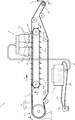
食品用コーティング装置1は、図1に示すように、ベルトコンベア2と、液体流下手段3と、液体貯留手段4と、搬送補助手段5と、落下遅延手段6とを有する。
As shown in FIG. 1, the food coating device 1 includes a
ベルトコンベア2は、無端環状ベルト23で対象物10を搬送する。液体流下手段3は、ベルトコンベア2の上方に設けられている。液体貯留手段4はベルトコンベア2の下方に設けられている。搬送補助手段5は、無端環状ベルト23の内側に設けられている。ベルトコンベアの落下遅延手段6は、ベルトコンベア2の下流の端近傍に設けられている。
The
ベルトコンベア2は、図1に示すように、無端環状ベルト23と、上流側プーリ21と、下流側プーリ22とを有する。図1において、矢印Aが指す方向が、搬送方向の上流側から下流側へ向かう方向である。
As shown in FIG. 1, the
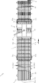
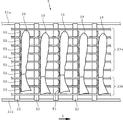
無端環状ベルト23は、図2に示すように、6本の多数列ベルト23aと3本の多数列ベルト23bからなる。多数列ベルト23a及び多数列ベルト23bは、それぞれ、上流側では無端環状ベルト23が上流側プーリ21に架けられており、下流側では無端環状ベルト23が下流側プーリ22に架けられている。多数列ベルト23a及び多数列ベルト23bは、搬送方向に対して直角方向に並設されている。
As shown in FIG. 2, the endless
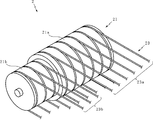
上流側プーリ21は、図2及び図3に示すように、回転軸に半径が異なる円柱21aと円柱21bとが固定されている。図7に示すように、対象物10が載置された場合、図7中の上側が対象物10の一端であり、下側が対象物10の他端となる。
As shown in FIGS. 2 and 3, the
図2及び図7に示すように、対象物10の他端側の一部のプーリは円柱21bである。対象物10のその他の部分のプーリが円柱21aである。
As shown in FIGS. 2 and 7, a part of the pulley on the other end side of the
図2及び図3に示すように、6本の多数列ベルト23aは、半径が大きい円柱21aの側周面に架けられている。3本の多数列ベルト23bは、半径が小さい方の円柱21bの側周面に架けられている。円柱21aの側周面には、各多数列ベルト23aを案内する複数の溝が軸線方向に所定の間隔で形成されている。円柱21bの側周面には、各多数列ベルト23bを案内する溝が形成されている。
As shown in FIGS. 2 and 3, the six
円柱21aと円柱21bとが固定されている回転軸が回転すると、円柱21bに架けられている多数列ベルト23bの搬送速度が、円柱21aに架けられている多数列ベルト23aの搬送速度より遅くなる。
When the rotation shaft that fixes the
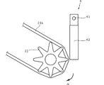
下流側プーリ22は、図4に示すように、放射状に延びる複数の延出部を有する。各延出部の先端には、多数列ベルト23a又は多数列ベルト23bが嵌る窪みが形成されている。下流側プーリ22は、多数列ベルト23a又は多数列ベルト23bと、複数の延出部の先端で接触する。
As shown in FIG. 4, the
図2に示すように、多数列ベルト23a及び多数列ベルト23bの合計と同数の下流側プーリ22は、それぞれ軸線方向に所定の間隔で軸に対して取り付けられている。各下流側プーリ22は、軸に固定されておらず、軸に対して自由に回転することができるようになっている。
As shown in FIG. 2, as many downstream-
図1及び図2では、図示を省略した駆動モータによって、上流側プーリ21及び下流側プーリ22は矢印αの方向に回転する。この上流側プーリ21及び下流側プーリ22の回転によって、多数列ベルト23a及び多数列ベルト23bは、搬送方向の上流側と下流側との間で循環可能となっている
In FIGS. 1 and 2, the
上流側プーリ21から下流側プーリ22に向かって、多数列ベルト23a及び多数列ベルト23bが並行するようになっている。
The
図1に示すように液体流下手段3は、ベルトコンベア2で搬送される対象物に向かって液体30を流下させる。
液体流下手段3は、液体30を流下させる位置を誘導するシュート板31を有する。シュート板31は、搬送方向に間隔を空けて4箇所に設けられている。
As shown in FIG. 1, the liquid flow-down means 3 causes the
The liquid flow-down means 3 has a
各シュート板31は、図5の両矢印Bに示すように、ベルトコンベア2の幅方向に移動可能となっている。シュート板31を移動させることによって、液体30をコーティングする対象物の範囲を調節できる。
Each
図1に示すように、液体流下手段3及び液体貯留手段4には、液体供給配管47が接続されている。液体供給配管47を通して、液体貯留手段4から液体流下手段3へと液体30が供給されるようになっている。
As shown in FIG. 1, a
図1及び図2では、構成が一部省略されているが、液体貯留手段4に貯留している液体30を液体流下手段3に供給し、液体流下手段3で流下させた液体30を回収し、回収した液体30を液体貯留手段4に貯留し、再度液体30を液体流下手段3に供給するという液体30の循環が可能となっている。 1 and 2, although the configuration is partially omitted, the liquid 30 stored in the liquid storage means 4 is supplied to the liquid flow-down means 3, and the liquid 30 flowed down by the liquid flow-down means 3 is recovered. It is possible to circulate the liquid 30 by storing the recovered liquid 30 in the liquid storage means 4 and supplying the liquid 30 to the liquid flow-down means 3 again.
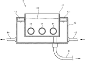
図6に示すように、液体貯留手段4は、外箱42と、内箱41とを有する。
As shown in FIG. 6, the liquid storage unit 4 has an
内箱41は、外箱42の内部に内箱固定部材43によって固定されている。
The
外箱42には、流体が貯留できるようになっている。流体は、ポンプ48、流体供給管45、流体排出管46によって、外箱42に貯留する流体を循環させることができる。この流体の循環、及び、流体の冷却又は加熱によって、流体の温度変化を抑制することができる。
A fluid can be stored in the
内箱41は、コーティング用の液体30を貯留することができる。内箱41は液体貯留手段の液体30を貯留する空間である。内箱41には筒体44が貫通している。その筒体44の両端は外箱42の内部空間に開口している。よって、外箱42に貯留する流体は、筒体44内を通過できるようになっている。
The
外箱42に貯留する流体の温度変化は抑制されているので、その流体が筒体44内を通過して、内箱41に貯留するコーティング用の液体30の温度変化を抑制することができる。
Since the temperature change of the fluid stored in the
図1、図2及び図7に示すように、搬送補助手段5は、上流側歯車54a,54bと、下流側歯車55a,55bと、チェーン51a,51bと、架渡部52と、爪部53とを有する。
As shown in FIGS. 1, 2 and 7, the conveyance assisting means 5 includes
上流側歯車54a,54bは、ベルトコンベア2の幅方向に対向する一対の歯車である。下流側歯車55a,55bも、ベルトコンベア2の幅方向に対向する一対の歯車である。
The upstream gears 54a and 54b are a pair of gears that face each other in the width direction of the
チェーン51aは搬送方向に並ぶ上流側歯車54aと下流側歯車55aに架けられている。チェーン51bは搬送方向に並ぶ上流側歯車54bと下流側歯車55bに架けられている。2本のチェーン51a,51bは、搬送方向に並行するようになっている。
The
並行する2本のチェーン51a,51bの間には、複数の架渡部52が所定の間隔で設けられている。
A plurality of bridging
図2及び図7に示すように、それぞれの架渡部52から、複数の爪部53が上方に向かって延出するように形成されている。爪部53は各多数列ベルト23a,23bの間から上方に向かって突出する。
As shown in FIGS. 2 and 7, a plurality of
上流側歯車54a,54b及び下流側歯車55a,55bが、図1の矢印β方向に回転する。爪部53は、ベルトコンベア2の搬送方向と同一方向に移動する。
The upstream gears 54a and 54b and the
多数列ベルト23の搬送方向の速度は、爪部53の搬送方向の速度より遅くなっている。したがって、爪部53が各多数列ベルト23a,23bの間から上方に向かって突出して各多数列ベルト23a,23bと同一方向に移動する区間では、多数列ベルト23a及び多数列ベルト23b上に載置されている対象物10は爪部53に押し付けられることとなる。
The speed of the
食品用コーティング装置1が、例えばフライ用のバッタリング装置である場合、対象物10はエビであり、液体30はバッターとなる。バッターを流下させるシュート板31は、搬送方向に間隔を空けて4箇所に設けられている。
When the food coating device 1 is, for example, a frying buttering device, the
最も上流側のシュート板31の下方をエビが通過して、エビがバッターでコーティングされると、バッターの高い粘度によってエビが曲がってしまう場合がある。
If the shrimp passes under the
しかし、対象物10であるエビが爪部53に押し付けられることで、下流側のシュート板31の下方を通過する場合でもエビが曲がることを抑制することができる。これにより、エビの表面にバッターを均一にコーティングすることができる。
However, by pressing the shrimp, which is the
落下遅延手段6は、ベルトコンベア2の下流の端の近傍に設けられている。落下遅延手段6は、支持部材61と揺動部材62とを有する。
The drop delay means 6 is provided near the downstream end of the
ベルトコンベア2上に載置された状態で搬送されてきた対象物10は、他端が揺動部材62に当接する。この対象物10の他端と揺動部材62との当接によって、ベルトコンベアの下流の端において、対象物10の一端側の落下より、対象物10の他端側の落下が遅れることとなる。
The other end of the
上記実施形態では、無端環状ベルト23は、6本の多数列ベルト23aと3本の多数列ベルト23bからなる場合について説明した。しかし、無端環状ベルトの本数は実施形態で説明した本数に限定されることはない。
In the above-described embodiment, the case where the endless
上記実施形態では、下流側プーリ22は、図1及び図4に示すように、放射状に延びる8個の延出部を有する場合について説明した。しかし、放射状に延びる延出部の個数は実施形態で説明した個数に限定されることはない。
In the above embodiment, the case where the
上記実施形態では、シュート板31で液体を流下させる場合について説明したが、これに限定されることはない。本発明の食品用コーティング装置は、例えばシャワー等で液体を流下させる液体流下手段を有していてもよい。
In the above embodiment, the case where the
上記実施形態では、図6では流体が液体である場合について図示したが、これに限定されることはない。本発明の食品用コーティング装置は、流体が気体であってもよい。 In the above embodiment, the case where the fluid is a liquid is illustrated in FIG. 6, but the present invention is not limited to this. In the food coating device of the present invention, the fluid may be a gas.
上記実施形態では、多数列ベルト23の搬送方向の速度は、爪部53の搬送方向の速度より遅くなっている場合について説明したが、これに限定されることはない。本発明の食品用コーティング装置は、多数列ベルト23の搬送方向の速度は、爪部53の搬送方向の速度より速くてもよい。
In the above embodiment, the case where the speed of the
上記実施形態では、食品用コーティング装置1が、例えばフライ用のバッタリング装置である例について説明したが、これに限定されることはない。本発明の食品用コーティング装置は、バッタリング装置以外の食品用コーティング装置であってもよい。 In the above embodiment, an example in which the food coating device 1 is, for example, a frying buttering device has been described, but the present invention is not limited to this. The food coating device of the present invention may be a food coating device other than the buttering device.
上記実施形態では、液体はバッターである例について説明したが、これに限定されることはない。本発明の食品用コーティング装置は、対象物に調味料等をコーティングする装置であってもよい。 In the above embodiment, an example in which the liquid is a batter has been described, but the liquid is not limited to this. The food coating apparatus of the present invention may be an apparatus that coats an object with a seasoning or the like.
上記実施形態では、対象物10はエビである例について説明したが、これに限定されることはない。本発明の食品用コーティング装置は、対象物は他の食品材料や加工食品等であってもよい。
In the above embodiment, the example in which the
1 食品用コーティング装置
2 ベルトコンベア
3 液体流下手段
4 液体貯留手段
5 搬送補助手段
6 落下遅延手段
10 対象物
21 上流側プーリ
21a 円柱
21b 円柱
22 下流側プーリ
23 無端環状ベルト
23a 多数列ベルト
23b 多数列ベルト
30 液体
31 シュート板
41 内箱
42 外箱
43 内箱固定部材
44 筒体
45 流体供給管
46 流体排出管
47 液体供給配管
48 ポンプ
51a チェーン
51b チェーン
52 架渡部
53 爪部
54a 上流側歯車
54b 上流側歯車
55a 下流側歯車
55b 下流側歯車
61 支持部材
62 揺動部材
1
Claims (1)
このベルトコンベアの上方に設けられており、ベルトコンベアで搬送される対象物に向かって液体を流下させる液体流下手段とを有し、
ベルトコンベアには、対象物が搬送方向に対して直角方向に対象物の一端から他端までが伸びるように載置され、ベルトコンベアの下流側の端部から対象物が次工程の装置へと落下するようになっており、
ベルトコンベアの下流側の端の近傍に、対象物の他端側の落下を遅らせる落下遅延手段をさらに有することを特徴とする食品用コーティング装置。 A belt conveyor for conveying the object,
It is provided above this belt conveyor and has a liquid flow-down means for flowing the liquid down toward the object conveyed by the belt conveyor,
On the belt conveyor , the object is placed so as to extend from one end to the other end of the object in a direction perpendicular to the transport direction, and the object is transferred from the downstream end of the belt conveyor to the device for the next step. It is supposed to fall,
A coating apparatus for food, further comprising a drop delay means for delaying the fall of the other end of the object near the downstream end of the belt conveyor.
Priority Applications (1)
| Application Number | Priority Date | Filing Date | Title |
|---|---|---|---|
| JP2018233244A JP6700635B2 (en) | 2018-12-13 | 2018-12-13 | Food coating equipment |
Applications Claiming Priority (1)
| Application Number | Priority Date | Filing Date | Title |
|---|---|---|---|
| JP2018233244A JP6700635B2 (en) | 2018-12-13 | 2018-12-13 | Food coating equipment |
Related Parent Applications (1)
| Application Number | Title | Priority Date | Filing Date |
|---|---|---|---|
| JP2017126950A Division JP6472099B2 (en) | 2017-06-29 | 2017-06-29 | Food coating equipment |
Publications (2)
| Publication Number | Publication Date |
|---|---|
| JP2019071884A JP2019071884A (en) | 2019-05-16 |
| JP6700635B2 true JP6700635B2 (en) | 2020-05-27 |
Family
ID=66542686
Family Applications (1)
| Application Number | Title | Priority Date | Filing Date |
|---|---|---|---|
| JP2018233244A Active JP6700635B2 (en) | 2018-12-13 | 2018-12-13 | Food coating equipment |
Country Status (1)
| Country | Link |
|---|---|
| JP (1) | JP6700635B2 (en) |
Families Citing this family (1)
| Publication number | Priority date | Publication date | Assignee | Title |
|---|---|---|---|---|
| CN121220727B (en) * | 2025-12-02 | 2026-03-24 | 山东天合堂食品股份有限公司 | Spherical food processing surface paste coating mechanism |
-
2018
- 2018-12-13 JP JP2018233244A patent/JP6700635B2/en active Active
Also Published As
| Publication number | Publication date |
|---|---|
| JP2019071884A (en) | 2019-05-16 |
Similar Documents
| Publication | Publication Date | Title |
|---|---|---|
| US10464757B2 (en) | Sprocket driven conveyor belt link and conveyor belt assembly | |
| US7717030B2 (en) | Single mold form fryer with product centering elements | |
| CN109803908B (en) | Method and apparatus for processing three-dimensional curved snack food pieces | |
| AU2016391621B2 (en) | High efficiency conveyor assembly | |
| JP6700635B2 (en) | Food coating equipment | |
| RU2004116819A (en) | DEVICE AND METHOD FOR BEATING AND UNLOADING FOOD TEST TAPES | |
| CN108430898A (en) | Equipment for receiving and conveying egg stream | |
| JP6472099B2 (en) | Food coating equipment | |
| AU2005217998B2 (en) | Forming and Cooking with Controlled Curtain Spillage | |
| JP6699833B2 (en) | Food coating equipment | |
| JP4932277B2 (en) | Conveyor | |
| JP4346675B2 (en) | Food dough heat treatment equipment | |
| CN110122541B (en) | Prawn separating and sequencing device | |
| US7434677B2 (en) | Apparatus for aligning meat products | |
| JP7153982B2 (en) | direction changer | |
| JP6643893B2 (en) | Nori grilling equipment | |
| JP7428896B2 (en) | Article alignment and conveyance device | |
| TW202330372A (en) | Conveying apparatus for conveying food products and heat treatment apparatus | |
| US12150587B1 (en) | Formed product grill | |
| KR20140115625A (en) | A conveyor belt device for cooling and transporting of fish cakes | |
| JP4234701B2 (en) | Food dough heat treatment equipment | |
| KR100937527B1 (en) | Food processing equipment | |
| KR100938944B1 (en) | Food processing equipment | |
| KR20090099385A (en) | Food processing equipment | |
| CN120283982A (en) | Immersed processing system and method and auger for an immersed processing system |
Legal Events
| Date | Code | Title | Description |
|---|---|---|---|
| A621 | Written request for application examination |
Free format text: JAPANESE INTERMEDIATE CODE: A621 Effective date: 20181221 |
|
| A131 | Notification of reasons for refusal |
Free format text: JAPANESE INTERMEDIATE CODE: A131 Effective date: 20191119 |
|
| A521 | Request for written amendment filed |
Free format text: JAPANESE INTERMEDIATE CODE: A523 Effective date: 20200117 |
|
| TRDD | Decision of grant or rejection written | ||
| A01 | Written decision to grant a patent or to grant a registration (utility model) |
Free format text: JAPANESE INTERMEDIATE CODE: A01 Effective date: 20200407 |
|
| A61 | First payment of annual fees (during grant procedure) |
Free format text: JAPANESE INTERMEDIATE CODE: A61 Effective date: 20200416 |
|
| R150 | Certificate of patent or registration of utility model |
Ref document number: 6700635 Country of ref document: JP Free format text: JAPANESE INTERMEDIATE CODE: R150 |
|
| R250 | Receipt of annual fees |
Free format text: JAPANESE INTERMEDIATE CODE: R250 |
|
| R250 | Receipt of annual fees |
Free format text: JAPANESE INTERMEDIATE CODE: R250 |
|
| R250 | Receipt of annual fees |
Free format text: JAPANESE INTERMEDIATE CODE: R250 |
|
| R250 | Receipt of annual fees |
Free format text: JAPANESE INTERMEDIATE CODE: R250 |