JP6700378B2 - Temporary occlusion balloon device and method for blocking blood flow through a vascular perforation - Google Patents
Temporary occlusion balloon device and method for blocking blood flow through a vascular perforation Download PDFInfo
- Publication number
- JP6700378B2 JP6700378B2 JP2018506554A JP2018506554A JP6700378B2 JP 6700378 B2 JP6700378 B2 JP 6700378B2 JP 2018506554 A JP2018506554 A JP 2018506554A JP 2018506554 A JP2018506554 A JP 2018506554A JP 6700378 B2 JP6700378 B2 JP 6700378B2
- Authority
- JP
- Japan
- Prior art keywords
- lumen
- inflatable balloon
- balloon
- catheter shaft
- distal
- Prior art date
- Legal status (The legal status is an assumption and is not a legal conclusion. Google has not performed a legal analysis and makes no representation as to the accuracy of the status listed.)
- Active
Links
Images


Classifications
-
- A—HUMAN NECESSITIES
- A61—MEDICAL OR VETERINARY SCIENCE; HYGIENE
- A61B—DIAGNOSIS; SURGERY; IDENTIFICATION
- A61B17/00—Surgical instruments, devices or methods, e.g. tourniquets
- A61B17/0057—Implements for plugging an opening in the wall of a hollow or tubular organ, e.g. for sealing a vessel puncture or closing a cardiac septal defect
-
- A—HUMAN NECESSITIES
- A61—MEDICAL OR VETERINARY SCIENCE; HYGIENE
- A61B—DIAGNOSIS; SURGERY; IDENTIFICATION
- A61B17/00—Surgical instruments, devices or methods, e.g. tourniquets
- A61B17/00491—Surgical glue applicators
-
- A—HUMAN NECESSITIES
- A61—MEDICAL OR VETERINARY SCIENCE; HYGIENE
- A61B—DIAGNOSIS; SURGERY; IDENTIFICATION
- A61B17/00—Surgical instruments, devices or methods, e.g. tourniquets
- A61B17/12—Surgical instruments, devices or methods, e.g. tourniquets for ligaturing or otherwise compressing tubular parts of the body, e.g. blood vessels, umbilical cord
- A61B17/12022—Occluding by internal devices, e.g. balloons or releasable wires
- A61B17/12099—Occluding by internal devices, e.g. balloons or releasable wires characterised by the location of the occluder
- A61B17/12109—Occluding by internal devices, e.g. balloons or releasable wires characterised by the location of the occluder in a blood vessel
-
- A—HUMAN NECESSITIES
- A61—MEDICAL OR VETERINARY SCIENCE; HYGIENE
- A61B—DIAGNOSIS; SURGERY; IDENTIFICATION
- A61B17/00—Surgical instruments, devices or methods, e.g. tourniquets
- A61B17/12—Surgical instruments, devices or methods, e.g. tourniquets for ligaturing or otherwise compressing tubular parts of the body, e.g. blood vessels, umbilical cord
- A61B17/12022—Occluding by internal devices, e.g. balloons or releasable wires
- A61B17/12027—Type of occlusion
- A61B17/1204—Type of occlusion temporary occlusion
-
- A—HUMAN NECESSITIES
- A61—MEDICAL OR VETERINARY SCIENCE; HYGIENE
- A61B—DIAGNOSIS; SURGERY; IDENTIFICATION
- A61B17/00—Surgical instruments, devices or methods, e.g. tourniquets
- A61B17/12—Surgical instruments, devices or methods, e.g. tourniquets for ligaturing or otherwise compressing tubular parts of the body, e.g. blood vessels, umbilical cord
- A61B17/12022—Occluding by internal devices, e.g. balloons or releasable wires
- A61B17/12131—Occluding by internal devices, e.g. balloons or releasable wires characterised by the type of occluding device
- A61B17/12136—Balloons
-
- A—HUMAN NECESSITIES
- A61—MEDICAL OR VETERINARY SCIENCE; HYGIENE
- A61B—DIAGNOSIS; SURGERY; IDENTIFICATION
- A61B17/00—Surgical instruments, devices or methods, e.g. tourniquets
- A61B17/00234—Surgical instruments, devices or methods, e.g. tourniquets for minimally invasive surgery
- A61B2017/00292—Surgical instruments, devices or methods, e.g. tourniquets for minimally invasive surgery mounted on or guided by flexible, e.g. catheter-like, means
-
- A—HUMAN NECESSITIES
- A61—MEDICAL OR VETERINARY SCIENCE; HYGIENE
- A61B—DIAGNOSIS; SURGERY; IDENTIFICATION
- A61B17/00—Surgical instruments, devices or methods, e.g. tourniquets
- A61B2017/00535—Surgical instruments, devices or methods, e.g. tourniquets pneumatically or hydraulically operated
- A61B2017/00557—Surgical instruments, devices or methods, e.g. tourniquets pneumatically or hydraulically operated inflatable
-
- A—HUMAN NECESSITIES
- A61—MEDICAL OR VETERINARY SCIENCE; HYGIENE
- A61B—DIAGNOSIS; SURGERY; IDENTIFICATION
- A61B17/00—Surgical instruments, devices or methods, e.g. tourniquets
- A61B17/0057—Implements for plugging an opening in the wall of a hollow or tubular organ, e.g. for sealing a vessel puncture or closing a cardiac septal defect
- A61B2017/00575—Implements for plugging an opening in the wall of a hollow or tubular organ, e.g. for sealing a vessel puncture or closing a cardiac septal defect for closure at remote site, e.g. closing atrial septum defects
- A61B2017/00597—Implements comprising a membrane
-
- A—HUMAN NECESSITIES
- A61—MEDICAL OR VETERINARY SCIENCE; HYGIENE
- A61B—DIAGNOSIS; SURGERY; IDENTIFICATION
- A61B17/00—Surgical instruments, devices or methods, e.g. tourniquets
- A61B17/0057—Implements for plugging an opening in the wall of a hollow or tubular organ, e.g. for sealing a vessel puncture or closing a cardiac septal defect
- A61B2017/00575—Implements for plugging an opening in the wall of a hollow or tubular organ, e.g. for sealing a vessel puncture or closing a cardiac septal defect for closure at remote site, e.g. closing atrial septum defects
- A61B2017/00623—Introducing or retrieving devices therefor
-
- A—HUMAN NECESSITIES
- A61—MEDICAL OR VETERINARY SCIENCE; HYGIENE
- A61B—DIAGNOSIS; SURGERY; IDENTIFICATION
- A61B17/00—Surgical instruments, devices or methods, e.g. tourniquets
- A61B17/0057—Implements for plugging an opening in the wall of a hollow or tubular organ, e.g. for sealing a vessel puncture or closing a cardiac septal defect
- A61B2017/00646—Type of implements
- A61B2017/0065—Type of implements the implement being an adhesive
-
- A—HUMAN NECESSITIES
- A61—MEDICAL OR VETERINARY SCIENCE; HYGIENE
- A61B—DIAGNOSIS; SURGERY; IDENTIFICATION
- A61B17/00—Surgical instruments, devices or methods, e.g. tourniquets
- A61B17/0057—Implements for plugging an opening in the wall of a hollow or tubular organ, e.g. for sealing a vessel puncture or closing a cardiac septal defect
- A61B2017/00646—Type of implements
- A61B2017/00659—Type of implements located only on one side of the opening
-
- A—HUMAN NECESSITIES
- A61—MEDICAL OR VETERINARY SCIENCE; HYGIENE
- A61B—DIAGNOSIS; SURGERY; IDENTIFICATION
- A61B17/00—Surgical instruments, devices or methods, e.g. tourniquets
- A61B17/0057—Implements for plugging an opening in the wall of a hollow or tubular organ, e.g. for sealing a vessel puncture or closing a cardiac septal defect
- A61B2017/00676—Implements for plugging an opening in the wall of a hollow or tubular organ, e.g. for sealing a vessel puncture or closing a cardiac septal defect promotion of self-sealing of the puncture
-
- A—HUMAN NECESSITIES
- A61—MEDICAL OR VETERINARY SCIENCE; HYGIENE
- A61B—DIAGNOSIS; SURGERY; IDENTIFICATION
- A61B90/00—Instruments, implements or accessories specially adapted for surgery or diagnosis and not covered by any of the groups A61B1/00 - A61B50/00, e.g. for luxation treatment or for protecting wound edges
- A61B90/39—Markers, e.g. radio-opaque or breast lesions markers
- A61B2090/3966—Radiopaque markers visible in an X-ray image
-
- A—HUMAN NECESSITIES
- A61—MEDICAL OR VETERINARY SCIENCE; HYGIENE
- A61M—DEVICES FOR INTRODUCING MEDIA INTO, OR ONTO, THE BODY; DEVICES FOR TRANSDUCING BODY MEDIA OR FOR TAKING MEDIA FROM THE BODY; DEVICES FOR PRODUCING OR ENDING SLEEP OR STUPOR
- A61M25/00—Catheters; Hollow probes
- A61M25/10—Balloon catheters
- A61M2025/1043—Balloon catheters with special features or adapted for special applications
- A61M2025/105—Balloon catheters with special features or adapted for special applications having a balloon suitable for drug delivery, e.g. by using holes for delivery, drug coating or membranes
-
- A—HUMAN NECESSITIES
- A61—MEDICAL OR VETERINARY SCIENCE; HYGIENE
- A61M—DEVICES FOR INTRODUCING MEDIA INTO, OR ONTO, THE BODY; DEVICES FOR TRANSDUCING BODY MEDIA OR FOR TAKING MEDIA FROM THE BODY; DEVICES FOR PRODUCING OR ENDING SLEEP OR STUPOR
- A61M25/00—Catheters; Hollow probes
- A61M25/10—Balloon catheters
- A61M2025/1043—Balloon catheters with special features or adapted for special applications
- A61M2025/1079—Balloon catheters with special features or adapted for special applications having radio-opaque markers in the region of the balloon
Landscapes
- Health & Medical Sciences (AREA)
- Life Sciences & Earth Sciences (AREA)
- Surgery (AREA)
- Molecular Biology (AREA)
- General Health & Medical Sciences (AREA)
- Biomedical Technology (AREA)
- Heart & Thoracic Surgery (AREA)
- Medical Informatics (AREA)
- Nuclear Medicine, Radiotherapy & Molecular Imaging (AREA)
- Animal Behavior & Ethology (AREA)
- Engineering & Computer Science (AREA)
- Public Health (AREA)
- Veterinary Medicine (AREA)
- Cardiology (AREA)
- Reproductive Health (AREA)
- Vascular Medicine (AREA)
- Media Introduction/Drainage Providing Device (AREA)
- Surgical Instruments (AREA)
Description
[0001] 本出願は、本願の権利者が所有する米国特許仮出願第62/203,711号(2015年8月11日出願、題名「TEMPORARY OCCLUSION BALLOON DEVICES AND METHODS FOR PREVENTING BLOOD FLOW THROUGH A VASCULAR PERFORATION」)、本願の権利者が所有する米国特許仮出願第62/212,023号(2015年8月31日出願、題名「TEMPORARY OCCLUSION BALLOON DEVICES AND METHODS FOR PREVENTING BLOOD FLOW THROUGH A VASCULAR PERFORATION」)、本願の権利者が所有する米国特許仮出願第62/212,025号(2015年8月31日出願、題名「TEMPORARY OCCLUSION BALLOON DEVICES AND METHODS FOR PREVENTING BLOOD FLOW THROUGH A VASCULAR PERFORATION」)、本願の権利者が所有する米国特許仮出願第62/233,869号(2015年9月28日出願、題名「TEMPORARY OCCLUSION BALLOON DEVICES AND HEMOSTATIC COMPOSITIONS FOR PREVENTING BLOOD FLOW THROUGH A VASCULAR PERFORATION」)、本願の権利者が所有する米国特許仮出願第62/234,376号(2015年9月29日出願、題名「TEMPORARY OCCLUSION BALLOON DEVICES AND METHODS FOR PREVENTING BLOOD FLOW THROUGH A VASCULAR PERFORATION」)、本願の権利者が所有する米国特許仮出願第62/260,945号(2015年11月30日出願、題名「TEMPORARY OCCLUSION BALLOON DEVICES AND METHODS FOR PREVENTING BLOOD FLOW THROUGH A VASCULAR PERFORATION」)、本願の権利者が所有する米国特許仮出願第62/297,785号(2016年2月19日出願、題名「TEMPORARY OCCLUSION BALLOON DEVICES AND METHODS FOR PREVENTING BLOOD FLOW THROUGH A VASCULAR PERFORATION」)、及び、本願の権利者が所有する米国特許仮出願第15/071,533号(2016年3月16日出願、題名「TEMPORARY OCCLUSION BALLOON DEVICES AND METHODS FOR PREVENTING BLOOD FLOW THROUGH A VASCULAR PERFORATION」)に関連し、それらの出願は、それらが教示する全てについてまた全ての目的で、参照によりその全体が本明細書に組込まれる。 BACKGROUND OF THE INVENTION [0001] This application is US provisional application No. 62/203,711 (filed on August 11, 2015, entitled "TEMPORARY OCCLUSION BALLONON DEVICES AND METHODS PREPENTING BLOOD FLOW THROUGHUAR VAR) owned by the right holder of the present application. )), U.S. Provisional Application No. 62/212,023 (filed Aug. 31, 2015, entitled "TEMPORARY OCCLUSION BALLONON DEVICES AND METHODS PREVENTING BLOOD FLOW THROUGH ARORFUL APR), owned by the right holder of the present application. US Provisional Application No. 62/212,025 (filed Aug. 31, 2015, entitled "TEMPORARY OCCLUSION DEVICES AND METHODS FOR PREBENTING BLOOD FLOW THROUGH A VARSUPARON)," US Patent Provisional Application No. 62/233,869 owned (filed on September 28, 2015, entitled "TEMPORARY OCCLUSION BALLOON DEVICES AND HEMOSTATIC COMPOSITIONS FOR PREBENTING BLOOD FLOW THROUGH IAR USAR", the owner of this application, VASU ARU Patent Provisional Application No. 62/234,376 (filed on September 29, 2015, entitled "TEMPORARY OCCLUSION BALLOON DEVICES AND METHODS FOR PREVENTING BLOOD FLOW THROUGH A US patent application owned by the US patent of the present application)" No. 62/260,945 (filed on Nov. 30, 2015, titled "TEMPORARY OCCLUSION BALLON DEVICES AND METHODS FOR PREVENTING BLOOD FLOW THR") OUGH A VASCULAR PERFORMATION"), U.S. Provisional Application No. 62/297,785 owned by the right holder of the present application )) and U.S. Provisional Application No. 15/071,533 owned by the right holder of the present application (filed on Mar. 16, 2016, entitled "TEMPORARY OCCLUSION BALLONON DEVICES AND METHODS PREPENTING BLOOD FLOW THROUGHU ARV)" , For all and for all purposes they teach, and are incorporated herein by reference in their entirety.
[0002] 本開示は、一般に、医療閉塞バルーンデバイス及び方法に関する。特に、本開示は、心臓リード線取外しプロシージャ中に形成される血管穿孔を通る血流を阻止するための一時的閉塞バルーンデバイス及び方法を提供する。 [0002] The present disclosure relates generally to medical occlusion balloon devices and methods. In particular, the present disclosure provides temporary occlusion balloon devices and methods for blocking blood flow through vascular perforations formed during a cardiac lead removal procedure.
[0003] ペースメーカ及びディフィブリレータ等の手術埋め込み式心臓ペーシングシステムは、心臓疾患の処置において重要な役割を果たす。最初のペースメーカが埋め込まれて以来50年して、技術は劇的に改善され、これらのシステムは、無数の生命を救い、その質を改善してきた。ペースメーカは、心拍数を上げることによって、又は、或る心不全患者について心臓の収縮を協調させることによって緩徐心調律を処置する。埋め込み型カーディオバータ−ディフィブリレータは、電気ショックを送出することによって危険な頻発心調律を停止させる。 [0003] Surgical implantable cardiac pacing systems such as pacemakers and defibrillators play an important role in the treatment of heart disease. Fifty years after the first pacemaker was implanted, technology has improved dramatically and these systems have saved countless lives and improved their quality. Pacemakers treat bradycardia by increasing the heart rate or by coordinating systole of the heart for some heart failure patients. Implantable cardioverter defibrillators stop dangerous frequent cardiac rhythms by delivering electric shocks.
[0004] 心臓ペーシングシステムは、通常、患者の身体の内部に留置されるタイミングデバイス及びリード線を含む。システムの1つの部分は、鎖骨の下の胸壁上の皮膚の下に通常留置される、電気回路及び電池を含むパルス発生器である。電池を置換するため、パルス発生器は、5〜10年ごとに簡単な手術プロシージャによって変更されなければならない。システムの別の部分は、パルス発生器と心臓との間を延びるワイヤ又はリード線を含む。ペースメーカにおいて、これらのリード線は、心臓の鼓動を速くするため、細かくタイミングをとったバーストの電気エネルギーを送出することによってデバイスが心拍数を上げることを可能にする。ディフィブリレータにおいて、リード線は、デバイスが、高エネルギーショックを送出し、潜在的に危険な頻発調律(心室頻拍又は細動)を元の通常調律に変換することを可能にする特別なコイルを有する。更に、リード線は、心臓の電気的活性に関する情報をペースメーカに送信する。 [0004] Cardiac pacing systems typically include timing devices and leads that are placed inside the patient's body. One part of the system is the pulse generator, which contains electrical circuitry and batteries, usually placed under the skin on the chest wall below the clavicle. To replace the battery, the pulse generator must be modified every 5-10 years by a simple surgical procedure. Another part of the system includes a wire or lead extending between the pulse generator and the heart. In pacemakers, these leads allow the device to increase heart rate by delivering finely timed bursts of electrical energy to accelerate the heart beat. In defibrillators, the leads are special coils that allow the device to deliver high energy shocks and convert potentially dangerous frequent rhythms (ventricular tachycardia or fibrillation) back to normal rhythm. Have. In addition, the leads send information to the pacemaker regarding the electrical activity of the heart.
[0005] これらの機能の両方について、リード線は、心臓組織と接触状態になければならない。ほとんどのリード線は、心臓の右側(右心房及び右心室)に接続する鎖骨下の静脈を通過する。幾つかの場合に、リード線は、静脈を通って挿入され、心腔内に誘導され、心腔内でリード線は心臓に付着される。他の事例において、リード線は、心臓の外側に付着される。心筋に付着されたままにするため、ほとんどのリード線は、端に小さなねじ及び/又はフック等の固定機構を有する。 [0005] For both of these functions, the leads must be in contact with heart tissue. Most leads pass through the subclavian veins that connect to the right side of the heart (right atrium and right ventricle). In some cases, the lead is inserted through a vein and guided into the heart chamber where it is attached to the heart. In other cases, the leads are attached to the outside of the heart. In order to remain attached to the myocardium, most leads have a locking mechanism such as a small screw and/or hook at the end.
[0006] リード線が身体内に埋め込まれた後の比較的短い期間内で、身体の自然な治癒プロセスは、リード線に沿ってまたおそらくはリード線の先端で瘢痕組織を形成し、それにより、リード線を患者の身体内で更に一層確実に留める。リード線は、通常、デバイス電池より長持ちするため、置換時にそれぞれの新しいパルス発生器(電池)に簡単に再接続される。リード線は身体内に永久的に埋め込まれるように設計されるが、時として、これらのリード線は、取外されなければならない又は取出されなければならない。リード線は、限定はしないが、感染、リード線経年劣化、及びリード線機能不全を含む多数の理由で患者から取外される。 [0006] Within a relatively short period of time after a lead is implanted within the body, the body's natural healing process forms scar tissue along the lead and possibly at the tip of the lead, thereby Fasten the leads even more securely within the patient's body. The leads typically last longer than the device battery and are easily reconnected to each new pulse generator (battery) during replacement. Although the leads are designed to be permanently implanted within the body, sometimes these leads have to be removed or removed. Leads are removed from a patient for a number of reasons including, but not limited to, infection, lead aging, and lead dysfunction.
[0007] リード線の取外し又は取出しは難しい。先に述べたように、身体の自然な治癒プロセスは、リード線を覆ってかつリード線に沿って、またおそらくリード線の先端に瘢痕組織を形成し、それにより、リード線の少なくとも一部を包み、また、リード線を患者の身体内に更に一層確実に留める。更に、リード線及び/又は組織は、血管壁に付着する。したがって、両方の結果は、患者の血管からリード線を取外す困難さを増加させる。 [0007] It is difficult to remove or take out the lead wire. As mentioned earlier, the body's natural healing process forms scar tissue over and along and possibly at the tip of the lead, thereby causing at least a portion of the lead to be removed. The wrapping and the leads are even more secure within the patient's body. Moreover, the leads and/or tissue adhere to the vessel wall. Therefore, both results increase the difficulty of removing the lead from the patient's blood vessel.
[0008] 種々のツールが、リード線取出しをより安全にかつより成功裡にするために開発されてきた。最新のリード線取出し技法は、機械的牽引、機械的デバイス、及びレーザデバイスを含む。機械的牽引は、ロック用スタイレットをリード線の中空部分に挿入し、次に、リード線を取外すためリード線を引張ることによって達成される。こうしたリード線ロック用デバイスの例は、Coe等に対する米国特許第6,167,315号において述べられ示される。その特許は、それが教示する全てについてまた全ての目的で、参照によりその全体が本明細書に組込まれる。 [0008] Various tools have been developed to make lead extraction safer and more successful. Modern lead extraction techniques include mechanical traction, mechanical devices, and laser devices. Mechanical traction is accomplished by inserting a locking stylet into the hollow portion of the lead and then pulling on the lead to remove it. An example of such a lead locking device is described and shown in US Pat. No. 6,167,315 to Coe et al. The patent is hereby incorporated by reference in its entirety for all and for all purposes it teaches.
[0009] リード線を取出す機械的デバイスは、リード線及び/又は周囲組織を覆って通過するシースと呼ばれる可撓性チューブを含む。シースは、一般に切断刃を含み、それにより、進められると、切断刃及びシースは、協働して、瘢痕組織を、リード線を囲む瘢痕組織を含む他の瘢痕組織から分離する。幾つかの例において、切断刃及びシースは、同様に、組織自身をリード線から分離する。リード線が周囲組織から分離されると、及び/又は、周囲組織が残留瘢痕組織から分離されると、リード線は、取外しのため、シースの中空管腔に挿入される、及び/又は、Taylorに対する米国特許第8,961,551号における先に述べた機械的牽引デバイス等の何らかの他の機械的デバイスを使用して患者の血管系から取外される。その特許は、それが教示する全てについてまた全ての目的で、参照によりその全体が本明細書に組込まれる。リード線を取出すために使用されるこうしたデバイス及び方法の例は、Graceに対する米国特許第5,651,781号において述べられ示される。その特許は、それが教示する全てについてまた全ての目的で、参照によりその全体が本明細書に組込まれる。 [0009] A mechanical device for removing a lead includes a flexible tube called a sheath that passes over the lead and/or surrounding tissue. The sheath generally includes a cutting blade such that, when advanced, the cutting blade and sheath cooperate to separate scar tissue from other scar tissue, including scar tissue surrounding the leads. In some examples, the cutting blade and sheath similarly separate the tissue itself from the leads. Once the lead is separated from the surrounding tissue and/or the surrounding tissue is separated from the residual scar tissue, the lead is inserted into the hollow lumen of the sheath for removal and/or the Taylor. To the patient's vasculature using some other mechanical device, such as the mechanical traction device described above in US Pat. The patent is hereby incorporated by reference in its entirety for all and for all purposes it teaches. An example of such a device and method used to extract leads is described and shown in US Pat. No. 5,651,781 to Grace. The patent is hereby incorporated by reference in its entirety for all and for all purposes it teaches.
[0010] 手術埋め込み式リード線を取外すために使用されるレーザカテーテルアセンブリ又はレーザシースの例は、商標名SLSII(商標)及びGlideLight(商標)の下でSpectranetics Corporationによる冠動脈レーザアテローム切除術カテーテルである。遠位端において、こうしたカテーテルは、管腔を囲む複数の光ファイバレーザエミッタを含む。光ファイバレーザエミッタがリード線を囲む組織を切断するにつれて、シースは、リード線及び周囲組織の上を摺動し、管腔に入る。 [0010] An example of a laser catheter assembly or laser sheath used to remove surgically implantable leads is the coronary laser atherectomy catheter by Spectranetics Corporation under the trade names SLSII™ and GlideLight™. At the distal end, such a catheter includes a plurality of fiber optic laser emitters that surround a lumen. As the fiber optic laser emitter cuts the tissue surrounding the lead, the sheath slides over the lead and surrounding tissue into the lumen.
[0011] リード線取出しは、一般に、非常に安全なプロシージャである。しかし、あらゆる侵襲的プロシージャの場合と同様に、潜在的リスクが存在する。例えば、リード線を取外すために先に論じたツールのうちの任意のツールを使用している間に、ツールは、ツールが通って移動する静脈又は動脈を、意図せずに、貫通、切断、又は穿孔し、それにより、血液が患者の血管系から漏出する可能性がある。血液が漏出するレートは、意図しない開口が患者の心臓の近くで生成される場合、高い。したがって、臨床医は、患者から漏出する血液の量を軽減し、それにより、患者に対する潜在的な長期損傷を最小にするため、その状況に迅速に対処しなければならない。 [0011] Lead extraction is generally a very safe procedure. However, as with any invasive procedure, there are potential risks. For example, while using any of the tools discussed above to remove a lead, the tool unintentionally penetrates, cuts, or cuts a vein or artery through which the tool travels. Or it may puncture, which may cause blood to leak from the patient's vasculature. The rate of blood leakage is high if an unintended opening is created near the patient's heart. Therefore, clinicians must address the situation promptly to reduce the amount of blood leaking from the patient, thereby minimizing potential long-term damage to the patient.
[0012] これらのまた他の必要性は、本開示の種々の態様、実施形態、及び構成によって対処される。幾つかの実施形態において、血管内の穿孔を閉塞させるためのデバイスは、第1の管腔及び第2の管腔を有するカテーテルシャフトを含む。第1の管腔は、ガイドワイヤ及び埋め込み式心臓リード線の少なくとも一方を受取るように適合され、第2の管腔は、膨張流体を受取るように適合される。第2の管腔は、カテーテルシャフトの長さに沿った或る場所において、0.65mm2と1.90mm2との間の断面積を含む。デバイスは、カテーテルシャフトによって保持される膨張可能バルーンを更に含む。膨張可能バルーンは、第2の管腔から膨張流体を受取るように適合される。膨張可能バルーンは、約65mm〜約80mmの作業長さ及び約20mm〜約25mmの膨張直径を有する。デバイスは、同様に、三日月形を含む断面積を第2の管腔内に含み、第2の管腔の断面積は約1mm2であり、三日月様の断面形状の半径は、約0.50mmと1.50mmとの間の半径を有する。 [0012] These and other needs are addressed by the various aspects, embodiments, and configurations of the present disclosure. In some embodiments, a device for occluding a perforation in a blood vessel comprises a catheter shaft having a first lumen and a second lumen. The first lumen is adapted to receive a guidewire and/or an implantable cardiac lead and the second lumen is adapted to receive an inflation fluid. The second lumen, at some locations along the length of the catheter shaft, including the cross-sectional area of between 0.65 mm 2 and 1.90 mm 2. The device further includes an inflatable balloon carried by the catheter shaft. The inflatable balloon is adapted to receive inflation fluid from the second lumen. The inflatable balloon has a working length of about 65 mm to about 80 mm and an inflated diameter of about 20 mm to about 25 mm. The device also includes a cross-sectional area within the second lumen that includes a crescent shape, the cross-sectional area of the second lumen is about 1 mm 2 , and the radius of the crescent-like cross-sectional shape is about 0.50 mm. And a radius of between 1.50 mm.
[0013] 幾つかの実施形態において、血管内の穿孔を閉塞させるためのデバイスは、血流喪失のレートを減少させ、穿孔の外科的修復を計画し始動するためのより多くの時間を可能にするため、止血組成物でコーティングした膨張可能バルーンを含む。止血組成物は、1つ又は複数の止血用血液凝固剤並びに1つ又は複数の補助剤及び/又は賦形剤を含み得る。 [0013] In some embodiments, a device for occluding a perforation in a blood vessel reduces the rate of blood flow loss, allowing more time to plan and initiate surgical repair of the perforation. To this end, an inflatable balloon coated with a hemostatic composition is included. The hemostatic composition may include one or more hemostatic coagulants and one or more adjuncts and/or excipients.
[0014] 段落[0012]によるデバイスにおいて、膨張可能バルーンはポリウレタンを含む。 [0014] In the device according to paragraph [0012], the inflatable balloon comprises polyurethane.
[0015] 段落[0012]〜[0014]のいずれか1つの段落によるデバイスにおいて、膨張可能バルーンは、近位テーパ付き部分、遠位テーパ付き部分、及び近位テーパ付き部分と遠位テーパ付き部分との間に配設される作業部分を含み、作業部分は、約20mm〜約25mmの膨張直径を有する、。 [0015] In the device according to any one of paragraphs [0012]-[0014], the inflatable balloon comprises a proximal tapered portion, a distal tapered portion, and a proximal tapered portion and a distal tapered portion. A working portion disposed between the working portion and the working portion, the working portion having an expanded diameter of about 20 mm to about 25 mm.
[0016] [0012]〜[0015]のいずれか1つの段落によるデバイスにおいて、第1の管腔及び第2の管腔は、カテーテルシャフト内で非同心に配設される。 [0016] In the device according to any one of paragraphs [0012]-[0015], the first lumen and the second lumen are non-concentrically disposed within the catheter shaft.
[0017] 段落[0012]〜[0016]のいずれか1つの段落によるデバイスにおいて、カテーテルシャフトによって保持される少なくとも1つのX線不透過性マーカを更に含む。 [0017] The device according to any one of paragraphs [0012] to [0016], further comprising at least one radiopaque marker carried by the catheter shaft.
[0018] 段落[0012]〜[0017]のいずれか1つの段落によるデバイスにおいて、少なくとも1つのX線不透過性マーカは、カテーテルシャフトの外周の周りに延在するバンドを含む。 [0018] In the device according to any one of paragraphs [0012]-[0017], the at least one radiopaque marker comprises a band extending around the outer circumference of the catheter shaft.
[0019] 段落[0012]〜[0018]のいずれか1つの段落によるデバイスにおいて、少なくとも1つのX線不透過性マーカは、少なくとも、第1のX線不透過性マーカ及び第2のX線不透過性マーカを含む。 [0019] In the device according to any one of paragraphs [0012] to [0018], at least one radiopaque marker comprises at least a first radiopaque marker and a second radiopaque marker. Includes a transparent marker.
[0020] 段落[0012]〜[0019]のいずれか1つの段落によるデバイスにおいて、少なくとも1つのX線不透過性マーカは、少なくとも第3のX線不透過性マーカを更に含む。 [0020] In the device according to any one of paragraphs [0012] to [0019], the at least one radiopaque marker further comprises at least a third radiopaque marker.
[0021] 段落[0012]〜[0020]のいずれか1つの段落によるデバイスにおいて、止血組成物は、血液凝固及び創傷治癒を促進するフィブリンベース凝固剤(例えば、フィブリンシーラント)を含む。 [0021] In the device according to any one of paragraphs [0012] to [0020], the hemostatic composition comprises a fibrin-based coagulant (eg, fibrin sealant) that promotes blood coagulation and wound healing.
[0022] 段落[0012]〜[0021]のいずれか1つの段落によるデバイスにおいて、止血組成物は、血液凝固及び創傷治癒を促進する1つ又は複数の凝固剤、及び、穿孔に隣接してバルーンを位置決めしている間の止血組成物の早期喪失を防止するためのコーティング剤を含む。 [0022] In the device according to any one of paragraphs [0012] to [0021], the hemostatic composition comprises one or more coagulants that promote blood coagulation and wound healing, and a balloon adjacent the perforations. Coatings to prevent premature loss of the hemostatic composition while positioning the.
[0023] 段落[0012]〜[0022]のいずれか1つの段落によるデバイスにおいて、膨張可能バルーンは、近位部分、遠位部分、及び近位部分と遠位部分との間に配設される中間部分を含み、第1、第2、及び第3のX線不透過性マーカは膨張可能バルーン内に保持され、第1のX線不透過性マーカは近位部分と軸方向に整列し、第2のX線不透過性マーカは中間部分と軸方向に整列し、第3のX線不透過性マーカは遠位部分と軸方向に整列する。 [0023] In the device according to any one of paragraphs [0012] to [0022], the inflatable balloon is disposed on the proximal portion, the distal portion, and between the proximal and distal portions. An intermediate portion, the first, second, and third radiopaque markers are retained within the inflatable balloon, the first radiopaque marker being axially aligned with the proximal portion, The second radiopaque marker is axially aligned with the middle portion and the third radiopaque marker is axially aligned with the distal portion.
[0024] 段落[0012]〜[0023]のいずれか1つの段落によるデバイスにおいて、膨張可能バルーンは、近位ネック、近位テーパ付き部分、作業部分、遠位テーパ付き部分、及び遠位ネックを含み、第1、第2、及び第3のX線不透過性マーカは膨張可能バルーン内に保持され、第1のX線不透過性マーカは、近位ネック及び近位テーパ付き部分の交差部と軸方向に整列し、第2のX線不透過性マーカは、近位テーパ付き部分及び作業部分の交差部と軸方向に整列し、第3のX線不透過性マーカは、作業部分及び遠位テーパ付き部分の交差部と軸方向に整列する。 [0024] In the device according to any one of paragraphs [0012]-[0023], the inflatable balloon comprises a proximal neck, a proximal tapered portion, a working portion, a distal tapered portion, and a distal neck. Including a first, a second, and a third radiopaque marker retained within the inflatable balloon, the first radiopaque marker at the intersection of the proximal neck and the proximal tapered portion. Axially aligned with a second radiopaque marker axially aligned with the intersection of the proximal tapered portion and the working portion, and a third radiopaque marker with the working portion and Align axially with the intersection of the distal tapered portions.
[0025] 段落[0012]〜[0024]のいずれか1つの段落によるデバイスにおいて、膨張可能バルーンの第1の端から第2の端への血液の通過を促進するように適合される第3の管腔を更に備える。 [0025] In the device according to any one of paragraphs [0012]-[0024], a third adapted to facilitate passage of blood from the first end to the second end of the inflatable balloon. It further comprises a lumen.
[0026] 段落[0012]〜[0025]のいずれか1つの段落によるデバイスにおいて、カテーテルシャフトは第3の管腔を含む。 [0026] In the device according to any one of paragraphs [0012]-[0025], the catheter shaft comprises a third lumen.
[0027] 段落[0012]〜[0026]のいずれか1つの段落によるデバイスにおいて、膨張可能バルーンによって着脱可能に保持される閉塞パッチを更に備え、閉塞パッチは、穿孔を閉塞させるため膨張可能バルーンから配備可能である。 [0027] The device according to any one of paragraphs [0012]-[0026], further comprising an occlusal patch removably retained by the inflatable balloon, the occlusal patch from the inflatable balloon to occlude the perforation. Can be deployed.
[0028] 段落[0012]〜[0027]のいずれか1つの段落によるデバイスにおいて、閉塞パッチは、血管内で閉塞パッチの位置を維持するように適合される少なくとも1つの接着剤を含む。 [0028] In the device according to any one of paragraphs [0012]-[0027], the occlusion patch comprises at least one adhesive adapted to maintain the position of the occlusion patch within the vessel.
[0029] 段落[0012]〜[0028]のいずれか1つの段落によるデバイスにおいて、少なくとも1つの接着剤は、熱、pH、及び光の少なくとも1つの付与によって活性化されるように適合される。 [0029] In the device according to any one of paragraphs [0012]-[0028], the at least one adhesive is adapted to be activated by the application of at least one of heat, pH, and light.
[0030] 段落[0012]〜[0029]のいずれか1つの段落によるデバイスにおいて、閉塞パッチは、スキャホールド構造であって、スキャホールド構造内での組織成長を促進するように適合される、スキャホールド構造を含む。 [0030] In the device according to any one of paragraphs [0012]-[0029], the occlusion patch is a scaffold structure, the scaffold being adapted to promote tissue growth within the scaffold structure. Includes hold structure.
[0031] 段落[0012]〜[0030]のいずれか1つの段落によるデバイスにおいて、閉塞パッチは、閉塞パッチの生体吸収を促進する幹細胞を含む。 [0031] In the device according to any one of paragraphs [0012] to [0030], the occlusive patch comprises stem cells that promote bioabsorption of the occlusive patch.
[0032] 段落[0012]〜[0031]のいずれか1つの段落によるデバイスにおいて、閉塞パッチは、創傷治癒を促進するように適合される少なくとも1つのホルモン剤を含む。 [0032] In the device according to any one of paragraphs [0012]-[0031], the occlusive patch comprises at least one hormonal agent adapted to promote wound healing.
[0033] 幾つかの実施形態において、血管内の穿孔を閉塞させるためのデバイスは、第1の管腔及び第2の管腔を有するカテーテルシャフトを含む。第1の管腔は、ガイドワイヤ及び埋め込み式心臓リード線の少なくとも一方を受取るように適合され、第2の管腔は膨張流体を受取るように適合される。デバイスは、カテーテルシャフトによって保持される膨張可能バルーンを更に含む。膨張可能バルーンは第2の管腔から膨張流体を受取るように適合される。膨張可能バルーンは、約85AのショアAデュロメータを有するポリウレタンを含む。 [0033] In some embodiments, a device for occluding a perforation in a blood vessel comprises a catheter shaft having a first lumen and a second lumen. The first lumen is adapted to receive a guidewire and/or an implantable cardiac lead and the second lumen is adapted to receive inflation fluid. The device further includes an inflatable balloon carried by the catheter shaft. The inflatable balloon is adapted to receive inflation fluid from the second lumen. The inflatable balloon comprises polyurethane with a Shore A durometer of about 85A.
[0034] 段落[0033]によるデバイスにおいて、第1の管腔及び第2の管腔は、カテーテルシャフト内で非同心に配設される。 [0034] In the device according to paragraph [0033], the first lumen and the second lumen are non-concentrically disposed within the catheter shaft.
[0035] 段落[0033]〜[0034]のいずれか1つの段落によるデバイスにおいて、第1の管腔及び第2の管腔は、カテーテルシャフト内で非同心に配設される。 [0035] In the device according to any one of paragraphs [0033]-[0034], the first lumen and the second lumen are non-concentrically disposed within the catheter shaft.
[0036] 段落[0033]〜[0035]のいずれか1つの段落によるデバイスにおいて、カテーテルシャフトによって保持される少なくとも1つのX線不透過性マーカを更に含む。 [0036] In the device according to any one of paragraphs [0033] to [0035], further comprising at least one radiopaque marker carried by the catheter shaft.
[0037] 段落[0033]〜[0036]のいずれか1つの段落によるデバイスにおいて、少なくとも1つのX線不透過性マーカは、カテーテルシャフトの外周の周りに延在するバンドを含む。 [0037] In the device according to any one of paragraphs [0033]-[0036], the at least one radiopaque marker comprises a band extending around the outer circumference of the catheter shaft.
[0038] 段落[0033]〜[0037]のいずれか1つの段落によるデバイスにおいて、少なくとも1つのX線不透過性マーカは、少なくとも、第1のX線不透過性マーカ及び第2のx線不透過性マーカを含む。 [0038] In the device according to any one of paragraphs [0033] to [0037], at least one radiopaque marker comprises at least a first radiopaque marker and a second radiopaque marker. Includes a transparent marker.
[0039] 段落[0033]〜[0038]のいずれか1つの段落によるデバイスにおいて、少なくとも1つのX線不透過性マーカは、少なくとも第3のX線不透過性マーカを含む。 [0039] In the device according to any one of paragraphs [0033] to [0038], the at least one radiopaque marker comprises at least a third radiopaque marker.
[0040] 段落[0033]〜[0039]のいずれか1つの段落によるデバイスにおいて、膨張可能バルーンは、近位部分、遠位部分、及び近位部分と遠位部分との間に配設される中間部分を含み、第1、第2、及び第3のX線不透過性マーカは膨張可能バルーン内に保持され、第1のX線不透過性マーカは近位部分と軸方向に整列し、第2のX線不透過性マーカは中間部分と軸方向に整列し、第3のX線不透過性マーカは遠位部分と軸方向に整列する。 [0040] In the device according to any one of paragraphs [0033]-[0039], the inflatable balloon is disposed on the proximal portion, the distal portion, and between the proximal and distal portions. An intermediate portion, the first, second, and third radiopaque markers are retained within the inflatable balloon, the first radiopaque marker being axially aligned with the proximal portion, The second radiopaque marker is axially aligned with the middle portion and the third radiopaque marker is axially aligned with the distal portion.
[0041] 段落[0033]〜[0040]のいずれか1つの段落によるデバイスにおいて、膨張可能バルーンの第1の端から第2の端への血液の通過を促進するように適合される第3の管腔を更に備える。 [0041] In the device according to any one of paragraphs [0033]-[0040], a third adapted to facilitate passage of blood from the first end to the second end of the inflatable balloon. It further comprises a lumen.
[0042] 段落[0033]〜[0041]のいずれか1つの段落によるデバイスにおいて、カテーテルシャフトは第3の管腔を含む。 [0042] In the device according to any one of paragraphs [0033]-[0041], the catheter shaft comprises a third lumen.
[0043] 段落[0033]〜[0042]のいずれか1つの段落によるデバイスにおいて、膨張可能バルーンは、血流喪失のレートを減少させるため止血組成物でコーティングされる。 [0043] In the device according to any one of paragraphs [0033]-[0042], the inflatable balloon is coated with a hemostatic composition to reduce the rate of blood flow loss.
[0044] 段落[0033]〜[0043]のいずれか1つの段落によるデバイスにおいて、止血組成物は、フィブリンベース凝固剤を備える。 [0044] In the device according to any one of paragraphs [0033]-[0043], the hemostatic composition comprises a fibrin-based coagulant.
[0045] 段落[0033]〜[0044]のいずれか1つの段落によるデバイスにおいて、止血組成物は、コーティング剤を備える。 [0045] In the device according to any one of paragraphs [0033] to [0044], the hemostatic composition comprises a coating agent.
[0046] 段落[0033]〜[0045]のいずれか1つの段落によるデバイスにおいて、膨張可能バルーンによって着脱可能に保持される閉塞パッチを更に備え、閉塞パッチは、穿孔を閉塞させるため膨張可能バルーンから配備可能である。 [0046] The device according to any one of paragraphs [0033]-[0045], further comprising an occlusal patch removably retained by the inflatable balloon, the occluding patch extending from the inflatable balloon to occlude the perforation. It can be deployed.
[0047] 段落[0033]〜[0046]のいずれか1つの段落によるデバイスにおいて、閉塞パッチは、血管内で閉塞パッチの位置を維持するように適合される少なくとも1つの接着剤を含む。 [0047] In the device according to any one of paragraphs [0033]-[0046], the occlusion patch comprises at least one adhesive adapted to maintain the position of the occlusion patch within the blood vessel.
[0048] 段落[0033]〜[0047]のいずれか1つの段落によるデバイスにおいて、少なくとも1つの接着剤は、熱、pH、及び光の少なくとも1つの付与によって活性化されるように適合される。 [0048] In the device according to any one of paragraphs [0033] to [0047], the at least one adhesive is adapted to be activated by the application of at least one of heat, pH, and light.
[0049] 段落[0033]〜[0048]のいずれか1つの段落によるデバイスにおいて、閉塞パッチは、スキャホールド構造であって、スキャホールド構造内での組織成長を促進するように適合される、スキャホールド構造を含む。 [0049] In the device according to any one of paragraphs [0033]-[0048], the occlusion patch is a scaffold structure, the scaffold being adapted to promote tissue growth within the scaffold structure. Includes hold structure.
[0050] 段落[0033]〜[0049]のいずれか1つの段落によるデバイスにおいて、閉塞パッチは、閉塞パッチの生体吸収を促進する幹細胞を含む。 [0050] In the device according to any one of paragraphs [0033]-[0049], the occlusive patch comprises stem cells that promote bioabsorption of the occlusive patch.
[0051] 段落[0033]〜[0050]のいずれか1つの段落によるデバイスにおいて、閉塞パッチは、創傷治癒を促進するように適合される少なくとも1つのホルモン剤を含む。 [0051] In the device according to any one of paragraphs [0033]-[0050], the occlusive patch comprises at least one hormonal agent adapted to promote wound healing.
[0052] 幾つかの実施形態において、血管内の穿孔を閉塞させるための方法は、(1)閉塞バルーンデバイスであって、第1の管腔及び第2の管腔を有するカテーテルシャフト、カテーテルシャフトによって保持される膨張可能バルーンを含み、膨張可能バルーンは約65mm〜約80mmの作業長を有し、また、膨張可能バルーンは約20mm〜約25mmの膨張直径を有する、閉塞バルーンデバイスを設けること;(2)膨張可能バルーンが穿孔に近接して位置決めされるまでカテーテルシャフトを血管内で進めること;及び(3)第2の管腔を介して膨張流体を膨張可能バルーンに送出することであって、それにより、膨張可能バルーンを膨張させ、それにより、穿孔を閉塞させる、送出することを含む。 [0052] In some embodiments, a method for occluding a perforation in a blood vessel includes: (1) an occlusion balloon device, the catheter shaft having a first lumen and a second lumen; Providing an occlusal balloon device including an inflatable balloon retained by, the inflatable balloon having a working length of about 65 mm to about 80 mm, and the inflatable balloon having an inflated diameter of about 20 mm to about 25 mm; (2) advancing the catheter shaft within the vessel until the inflatable balloon is positioned proximate the perforation; and (3) delivering inflation fluid to the inflatable balloon via a second lumen. , Thereby inflating the inflatable balloon, thereby occluding the perforation and delivering.
[0053] 段落[0052]による方法において、膨張流体は、生理食塩水及び造影溶液を含む。 [0053] In the method according to paragraph [0052], the inflation fluid comprises saline and contrast solution.
[0054] 段落[0052]〜[0053]のいずれか1つの段落による方法において、膨張流体は、約80パーセント生理食塩水及び約20パーセント造影溶液を含む。 [0054] In the method according to any one of paragraphs [0052]-[0053], the inflation fluid comprises about 80 percent saline and about 20 percent contrast solution.
[0055] 段落[0052]〜[0054]のいずれか1つの段落による方法において、膨張流体を膨張可能バルーンに送出することは、膨張流体を約2〜約3気圧の範囲内の圧力で送出することを含む。 [0055] In the method according to any one of paragraphs [0052]-[0054], delivering inflation fluid to the inflatable balloon delivers inflation fluid at a pressure within the range of about 2 to about 3 atmospheres. Including that.
[0056] 段落[0052]〜[0055]のいずれか1つの段落による方法において、膨張可能バルーンの第1の端から第2の端への血液の通過を促進するように適合される第3の管腔を更に備える。 [0056] In the method according to any one of paragraphs [0052]-[0055], a third adapted to facilitate passage of blood from the first end to the second end of the inflatable balloon. It further comprises a lumen.
[0057] 段落[0052]〜[0056]のいずれか1つの段落による方法において、カテーテルシャフトは第3の管腔を含む。 [0057] In the method according to any one of paragraphs [0052]-[0056], the catheter shaft comprises a third lumen.
[0058] 段落[0052]〜[0057]のいずれか1つの段落による方法において、膨張可能バルーンは止血組成物でコーティングされ、膨張流体を膨張可能バルーンに送出することは、穿孔の部位(site)において止血組成物を血管組織と接触状態にもたらす。 [0058] In the method according to any one of paragraphs [0052]-[0057], the inflatable balloon is coated with a hemostatic composition and delivering the inflation fluid to the inflatable balloon is at the site of perforation. In bringing the hemostatic composition into contact with vascular tissue.
[0059] 段落[0052]〜[0058]のいずれか1つの段落による方法において、膨張可能バルーンは、血流喪失のレートを減少させるため止血組成物でコーティングされる。 [0059] In the method according to any one of paragraphs [0052]-[0058], the inflatable balloon is coated with a hemostatic composition to reduce the rate of blood flow loss.
[0060] 段落[0052]〜[0059]のいずれか1つの段落による方法において、止血組成物は、フィブリンベース凝固剤を備える。 [0060] In the method according to any one of paragraphs [0052] to [0059], the hemostatic composition comprises a fibrin-based coagulant.
[0061] 段落[0052]〜[0060]のいずれか1つの段落による方法において、止血組成物はコーティング剤を備える。 [0061] In the method according to any one of paragraphs [0052] to [0060], the hemostatic composition comprises a coating agent.
[0062] 段落[0052]〜[0061]のいずれか1つの段落による方法において、閉塞バルーンデバイスは、膨張可能バルーンによって着脱可能に保持される閉塞パッチを備え、膨張流体を膨張可能バルーンに送出することであって、それにより、膨張可能バルーンを膨張させ、それにより、穿孔を閉塞させる、送出することは、膨張可能バルーンから閉塞パッチを配備し、それにより、穿孔を閉塞させることを含む。 [0062] In the method according to any one of paragraphs [0052]-[0061], the occlusion balloon device comprises an occlusion patch removably retained by the inflatable balloon and delivers inflation fluid to the inflatable balloon. Thus, inflating the inflatable balloon, thereby occluding the perforation, delivering, includes deploying an occlusive patch from the inflatable balloon, thereby occluding the perforation.
[0063] 段落[0052]〜[0062]のいずれか1つの段落による方法において、閉塞パッチは少なくとも1つの接着剤を含み、方法は、血管内で閉塞パッチを留めるため少なくとも1つの接着剤を活性化することを更に有する。 [0063] In the method according to any one of paragraphs [0052]-[0062], the occlusive patch comprises at least one adhesive, the method activating the at least one adhesive to anchor the occlusive patch in a blood vessel. Further having
[0064] 段落[0052]〜[0063]のいずれか1つの段落による方法において、血管内で閉塞パッチを留めるため少なくとも1つの接着剤を活性化することは、熱、pH、及び光の少なくとも1つを付与することを含む。 [0064] In the method according to any one of paragraphs [0052] to [0063], activating at least one adhesive to anchor the occlusive patch in the blood vessel comprises at least one of heat, pH, and light. Including one.
[0065] 段落[0052]〜[0064]のいずれか1つの段落による方法において、閉塞パッチは、スキャホールド構造であって、スキャホールド構造内での組織成長を促進するように適合される、スキャホールド構造を含む。 [0065] In the method of any one of paragraphs [0052]-[0064], the occlusion patch is a scaffold structure, the scaffold being adapted to promote tissue growth within the scaffold structure. Includes hold structure.
[0066] 段落[0052]〜[0065]のいずれか1つの段落による方法において、閉塞パッチは、閉塞パッチの生体吸収を促進する幹細胞を含む。 [0066] In the method of any one of paragraphs [0052]-[0065], the occlusive patch comprises stem cells that promote bioabsorption of the occlusive patch.
[0067] 段落[0052]〜[0066]のいずれか1つの段落による方法において、閉塞パッチは、創傷治癒を促進するように適合される少なくとも1つのホルモン剤を含む。 [0067] In the method according to any one of paragraphs [0052]-[0066], the occlusive patch comprises at least one hormonal agent adapted to promote wound healing.
[0068] 幾つかの実施形態において、血管内の穿孔を閉塞させるためのデバイスは、カテーテルシャフトであって、第1の管腔及び第2の管腔を有し、第1の管腔はガイドワイヤ及び埋め込み式心臓リード線の少なくとも一方を受取るように適合され、第2の管腔は膨張流体を受取るように適合される、カテーテルシャフト、及び、膨張可能バルーンを備え、膨張可能バルーンは、カテーテルシャフトによって保持され、第2の管腔から膨張流体を受取るように適合され、膨張可能バルーンは、約115mm〜約65mmの長さを有する作業部分を備え、作業部分は、第1の外径から第2の外径まで内側にテーパ付けされる。 [0068] In some embodiments, the device for occluding a perforation in a blood vessel is a catheter shaft having a first lumen and a second lumen, the first lumen being a guide. A catheter shaft adapted to receive at least one of a wire and an implantable cardiac lead and a second lumen adapted to receive inflation fluid, and an inflatable balloon, the inflatable balloon comprising a catheter The inflatable balloon, which is retained by the shaft and adapted to receive inflation fluid from the second lumen, comprises a working portion having a length of about 115 mm to about 65 mm, the working portion extending from the first outer diameter. Tapered inward to the second outer diameter.
[0069] 段落[0068]によるデバイスにおいて、作業部分は、第1の外径から第2の外径まで内側に一定傾斜でテーパ付けされる。 [0069] In the device according to paragraph [0068], the working portion is tapered inwardly from the first outer diameter to the second outer diameter at a constant slope.
[0070] 段落[0068]〜[0069]のいずれか1つの段落によるデバイスにおいて、作業部分は、第1の外径から第2の外径まで内側に一定傾斜でテーパ付けされる。 [0070] In the device according to any one of paragraphs [0068]-[0069], the working portion is tapered inwardly from the first outer diameter to the second outer diameter at a constant slope.
[0071] 段落[0068]〜[0070]のいずれか1つの段落によるデバイスにおいて、第1の外径は膨張可能バルーンの近位部分に配設され、第2の外径は膨張可能バルーンの遠位部分に配設される。 [0071] In the device according to any one of paragraphs [0068]-[0070], the first outer diameter is disposed in a proximal portion of the inflatable balloon and the second outer diameter is in the distal portion of the inflatable balloon. It is arranged in the position part.
[0072] 段落[0068]〜[0071]のいずれか1つの段落によるデバイスにおいて、第1の外径は約35mm〜約50mmの範囲内にある。 [0072] In the device according to any one of paragraphs [0068] to [0071], the first outer diameter is in the range of about 35 mm to about 50 mm.
[0073] 段落[0068]〜[0072]のいずれか1つの段落によるデバイスにおいて、第2の外径は約16mm〜約30mmの範囲内にある。 [0073] In the device according to any one of paragraphs [0068] to [0072], the second outer diameter is in the range of about 16 mm to about 30 mm.
[0074] 段落[0068]〜[0073]のいずれか1つの段落によるデバイスにおいて、カテーテルシャフトによって保持される少なくとも1つのX線不透過性マーカを更に備える。 [0074] In the device according to any one of paragraphs [0068] to [0073], further comprising at least one radiopaque marker carried by the catheter shaft.
[0075] 段落[0068]〜[0074]のいずれか1つの段落によるデバイスにおいて、膨張可能バルーンはポリウレタンを備える。 [0075] In the device according to any one of paragraphs [0068]-[0074], the inflatable balloon comprises polyurethane.
[0076] 段落[0068]〜[0075]のいずれか1つの段落によるデバイスにおいて、膨張可能バルーンは、約85AのショアAデュロメータを有するポリウレタンを備える。 [0076] In the device according to any one of paragraphs [0068]-[0075], the inflatable balloon comprises polyurethane having a Shore A durometer of about 85A.
[0077] 幾つかの実施形態において、血管内の穿孔を閉塞させるためのデバイスは、カテーテルシャフトであって、第1の管腔及び第2の管腔を有し、第1の管腔はガイドワイヤ及び埋め込み式心臓リード線の少なくとも一方を受取るように適合され、第2の管腔は膨張流体を受取るように適合される、カテーテルシャフト、及び、膨張可能バルーンを備え、膨張可能バルーンは、カテーテルシャフトによって保持され、第2の管腔から膨張流体を受取るように適合され、膨張可能バルーンは、約85AのショアAデュロメータを有するポリウレタンを備え、また、膨張可能バルーンは、第1の外径から第2の外径まで内側にテーパ付けされる作業部分を有する。 [0077] In some embodiments, the device for occluding a perforation in a blood vessel is a catheter shaft having a first lumen and a second lumen, the first lumen being a guide. A catheter shaft adapted to receive at least one of a wire and an implantable cardiac lead and a second lumen adapted to receive inflation fluid, and an inflatable balloon, the inflatable balloon comprising a catheter Retained by the shaft and adapted to receive inflation fluid from the second lumen, the inflatable balloon comprises polyurethane having a Shore A durometer of about 85 A, and the inflatable balloon is configured to extend from a first outer diameter. It has a working portion that tapers inwardly to a second outer diameter.
[0078] 段落[0077]によるデバイスにおいて、作業部分は、第1の外径から第2の外径まで内側に一定傾斜でテーパ付けされる。 [0078] In the device according to paragraph [0077], the working portion is tapered inwardly from the first outer diameter to the second outer diameter with a constant slope.
[0079] 段落[0077]〜[0078]のいずれか1つの段落によるデバイスにおいて、第1の外径は膨張可能バルーンの近位部分に配設され、第2の外径は膨張可能バルーンの遠位部分に配設される。 [0079] In the device according to any one of paragraphs [0077]-[0078], the first outer diameter is disposed in a proximal portion of the inflatable balloon and the second outer diameter is in the distal portion of the inflatable balloon. It is arranged in the position part.
[0080] 段落[0077]〜[0079]のいずれか1つの段落によるデバイスにおいて、第1の外径は約35mm〜約50mmの範囲内にある。 [0080] In a device according to any one of paragraphs [0077]-[0079], the first outer diameter is in the range of about 35 mm to about 50 mm.
[0081] 段落[0077]〜[0080]のいずれか1つの段落によるデバイスにおいて、第2の外径は約16mm〜約30mmの範囲内にある。 [0081] In the device according to any one of paragraphs [0077] to [0080], the second outer diameter is in the range of about 16 mm to about 30 mm.
[0082] 段落[0077]〜[0081]のいずれか1つの段落によるデバイスにおいて、カテーテルシャフトによって保持される少なくとも1つのX線不透過性マーカを更に備える。 [0082] The device according to any one of paragraphs [0077] to [0081], further comprising at least one radiopaque marker carried by the catheter shaft.
[0083] 段落[0077]〜[0082]のいずれか1つの段落によるデバイスにおいて、膨張可能バルーンはポリウレタンを備える。 [0083] In the device according to any one of paragraphs [0077]-[0082], the inflatable balloon comprises polyurethane.
[0084] 段落[0077]〜[0083]のいずれか1つの段落によるデバイスにおいて、膨張可能バルーンは、約85AのショアAデュロメータを有するポリウレタンを備える。 [0084] In the device according to any one of paragraphs [0077]-[0083], the inflatable balloon comprises polyurethane having a Shore A durometer of about 85A.
[0085] 幾つかの実施形態において、血管内の穿孔を閉塞させるための方法であって、当該方法は、閉塞バルーンデバイスであって、第1の管腔及び第2の管腔を有するカテーテルシャフト、カテーテルシャフトによって保持される膨張可能バルーンを備え、膨張可能バルーンは約115mm〜約65mmの長さを有する作業部分を備え、また、作業部分は第1の外径から第2の外径まで内側にテーパ付けされる、閉塞バルーンデバイスを設けること;膨張可能バルーンが穿孔に近接して位置決めされるまでカテーテルシャフトを血管内で進めること;及び第2の管腔を介して膨張流体を膨張可能バルーンに送出することであって、それにより、膨張可能バルーンを膨張させ、それにより、穿孔を閉塞させる、送出することを有する。 [0085] In some embodiments, a method for occluding a perforation in a blood vessel, the method being an occlusion balloon device, the catheter shaft having a first lumen and a second lumen. An inflatable balloon carried by the catheter shaft, the inflatable balloon comprising a working portion having a length of about 115 mm to about 65 mm, the working portion being inner from a first outer diameter to a second outer diameter Providing an occlusive balloon device that is tapered to the catheter; advancing the catheter shaft within the vessel until the inflatable balloon is positioned proximate the puncture; and inflating the inflation fluid through a second lumen. Delivering to the inflatable balloon, thereby inflating the inflatable balloon, thereby occluding the perforation.
[0086] 段落[0085]による方法において、膨張流体は、生理食塩水及び造影溶液を含む。 [0086] In the method according to paragraph [0085], the inflation fluid comprises saline and a contrast solution.
[0087] 段落[0085]〜[0086]のいずれか1つの段落による方法において、膨張流体は、約80パーセント生理食塩水及び約20パーセント造影溶液を含む。 [0087] In the method according to any one of paragraphs [0085]-[0086], the inflation fluid comprises about 80 percent saline and about 20 percent contrast solution.
[0088] 段落[0085]〜[0087]のいずれか1つの段落による方法において、膨張流体を膨張可能バルーンに送出することは、膨張流体を約2〜約3気圧の範囲内の圧力で送出することを有する。 [0088] In the method according to any one of paragraphs [0085]-[0087], delivering inflation fluid to the inflatable balloon delivers inflation fluid at a pressure within the range of about 2 to about 3 atmospheres. To have that.
[0089] 幾つかの実施形態において、血管内の穿孔を閉塞させるためのデバイスであって、当該デバイスは、カテーテルシャフトであって、第1の管腔及び第2の管腔を有し、第1の管腔はガイドワイヤ及び埋め込み式心臓リード線の少なくとも一方を受取るように適合され、第2の管腔は膨張流体を受取るように適合される、カテーテルシャフト、及び、膨張可能バルーンを備え、膨張可能バルーンは、カテーテルシャフトによって保持され、第2の管腔から膨張流体を受取るように適合され、膨張可能バルーンは、約115mm〜約65mmの長さを有する作業部分を備え、作業部分は第1の外径から第2の外径まで内側にテーパ付けされ、膨張可能バルーンは、約1.3:1〜約3.3:1の長さと第1の外径との第1の比及び約2.2:1〜約7.2:1の長さと第2の外径との第2の比を備える。 [0089] In some embodiments, a device for occluding a perforation in a blood vessel, the device being a catheter shaft having a first lumen and a second lumen, One lumen adapted to receive a guidewire and/or an implantable cardiac lead, and a second lumen adapted to receive inflation fluid, comprising a catheter shaft and an inflatable balloon, The inflatable balloon is retained by the catheter shaft and is adapted to receive inflation fluid from the second lumen, the inflatable balloon comprising a working portion having a length of about 115 mm to about 65 mm, the working portion being a first portion. Tapering inward from an outer diameter of 1 to a second outer diameter, the inflatable balloon has a length to first ratio of about 1.3:1 to about 3.3:1 and a first outer diameter of A second ratio of length to second outer diameter of from about 2.2:1 to about 7.2:1.
[0090] 幾つかの実施形態において、血管内の穿孔を閉塞させるためのデバイスは、カテーテルシャフトであって、第1の管腔及び第2の管腔を有し、第1の管腔はガイドワイヤ及び埋め込み式心臓リード線の少なくとも一方を受取るように適合され、第2の管腔は膨張流体を受取るように適合される、カテーテルシャフト、及び、膨張可能バルーンを備え、膨張可能バルーンは、カテーテルシャフトによって保持され、第2の管腔から膨張流体を受取るように適合され、膨張可能バルーンは、約125mm〜約85mmの長さを有する作業部分を備え、作業部分は、それぞれが異なる外径を有する複数のセクションを備える。 [0090] In some embodiments, the device for occluding a perforation in a blood vessel is a catheter shaft having a first lumen and a second lumen, the first lumen being a guide. A catheter shaft and an inflatable balloon adapted to receive a wire and/or an implantable cardiac lead, the second lumen adapted to receive an inflation fluid, the inflatable balloon comprising a catheter Retained by the shaft and adapted to receive inflation fluid from the second lumen, the inflatable balloon comprises a working portion having a length of about 125 mm to about 85 mm, each working portion having a different outer diameter. A plurality of sections having.
[0091] 段落[0090]によるデバイスにおいて、作業部分の複数のセクションは、第1の外径を有する第1のセクション;第2の外径を有する第2のセクション;及び第3の外径を有する第3のセクションを備える。 [0091] In the device according to paragraph [0090], the plurality of sections of the working portion include a first section having a first outer diameter; a second section having a second outer diameter; and a third outer diameter. A third section having.
[0092] 段落[0090]〜[0091]のいずれか1つの段落によるデバイスにおいて、第1の外径は第2の外径より大きく、第2の外径は第3の外径より大きい。 [0092] In the device according to any one of paragraphs [0090] to [0091], the first outer diameter is greater than the second outer diameter and the second outer diameter is greater than the third outer diameter.
[0093] 段落[0090]〜[0092]のいずれか1つの段落によるデバイスにおいて、第1のセクションは第2のセクションに対して近位に配設され、第2のセクションは第3のセクションに対して近位に配設される。 [0093] In the device according to any one of paragraphs [0090] to [0092], the first section is disposed proximal to the second section and the second section is disposed in the third section. It is arranged proximally.
[0094] 段落[0090]〜[0093]のいずれか1つの段落によるデバイスにおいて、第1の外径は約60mm〜約40mmの範囲内にある。 [0094] In the device according to any one of paragraphs [0090] to [0093], the first outer diameter is in the range of about 60 mm to about 40 mm.
[0095] 段落[0090]〜[0094]のいずれか1つの段落によるデバイスにおいて、第2の外径は約30mm〜約10mmの範囲内にある。 [0095] In the device according to any one of paragraphs [0090] to [0094], the second outer diameter is in the range of about 30 mm to about 10 mm.
[0096] 段落[0090]〜[0095]のいずれか1つの段落によるデバイスにおいて、第3の外径は約26mm〜約6mmの範囲内にある。 [0096] In the device according to any one of paragraphs [0090] to [0095], the third outer diameter is in the range of about 26 mm to about 6 mm.
[0097] 段落[0090]〜[0096]のいずれか1つの段落によるデバイスにおいて、第1のセクションは、約18mm〜約25mmの範囲内の長さを有する。 [0097] In the device according to any one of paragraphs [0090] to [0096], the first section has a length in the range of about 18 mm to about 25 mm.
[0098] 段落[0090]〜[0097]のいずれか1つの段落によるデバイスにおいて、第2のセクションは、約52mm〜約60mmの範囲内の長さを有する。 [0098] In the device according to any one of paragraphs [0090] to [0097], the second section has a length in the range of about 52 mm to about 60 mm.
[0099] 段落[0090]〜[0098]のいずれか1つの段落によるデバイスにおいて、第3のセクションは、約20mm〜約40mmの範囲内の長さを有する。 [0099] In the device according to any one of paragraphs [0090] to [0098], the third section has a length in the range of about 20 mm to about 40 mm.
[0100] 段落[0090]〜[0099]のいずれか1つの段落によるデバイスにおいて、カテーテルシャフトによって保持される少なくとも1つのX線不透過性マーカを更に備える。 [0100] The device according to any one of paragraphs [0090] to [0099], further comprising at least one radiopaque marker carried by the catheter shaft.
[0101] 段落[0090]〜[0100]のいずれか1つの段落によるデバイスにおいて、膨張可能バルーンはポリウレタンを備える。 [0101] In the device according to any one of paragraphs [0090] to [0100], the inflatable balloon comprises polyurethane.
[0102] 段落[0090]〜[0101]のいずれか1つの段落によるデバイスにおいて、膨張可能バルーンは、約85AのショアAデュロメータを有するポリウレタンを備える。 [0102] In the device according to any one of paragraphs [0090] to [0101], the inflatable balloon comprises polyurethane having a Shore A durometer of about 85A.
[0103] 幾つかの実施形態において、血管内の穿孔を閉塞させるためのデバイスは、カテーテルシャフトであって、第1の管腔及び第2の管腔を有し、第1の管腔はガイドワイヤ及び埋め込み式心臓リード線の少なくとも一方を受取るように適合され、第2の管腔は膨張流体を受取るように適合される、カテーテルシャフト、及び、膨張可能バルーンを備え、膨張可能バルーンは、カテーテルシャフトによって保持され、第2の管腔から膨張流体を受取るように適合され、膨張可能バルーンは、約85AのショアAデュロメータを有するポリウレタンを備え、また、膨張可能バルーンは、それぞれが異なる外径を有する複数のセクションを備える作業部分を有する。 [0103] In some embodiments, the device for occluding a perforation in a blood vessel is a catheter shaft having a first lumen and a second lumen, the first lumen being a guide. A catheter shaft and an inflatable balloon adapted to receive a wire and/or an implantable cardiac lead, the second lumen adapted to receive an inflation fluid, the inflatable balloon comprising a catheter Retained by the shaft and adapted to receive inflation fluid from the second lumen, the inflatable balloon comprises polyurethane having a Shore A durometer of about 85 A, and the inflatable balloons each have a different outer diameter. Having a working portion with a plurality of sections having.
[0104] 段落[0103]によるデバイスにおいて、作業部分の複数のセクションは、第1の外径を有する第1のセクション;第2の外径を有する第2のセクション;及び第3の外径を有する第3のセクションを備える。 [0104] In the device according to paragraph [0103], the plurality of sections of the working portion include a first section having a first outer diameter; a second section having a second outer diameter; and a third outer diameter. A third section having.
[0105] 段落[0103]〜[0104]のいずれか1つの段落によるデバイスにおいて、第1の外径は第2の外径より大きく、第2の外径は第3の外径より大きい。 [0105] In the device according to any one of paragraphs [0103] to [0104], the first outer diameter is greater than the second outer diameter and the second outer diameter is greater than the third outer diameter.
[0106] 段落[0103]〜[0105]のいずれか1つの段落によるデバイスにおいて、第1のセクションは第2のセクションに対して近位に配設され、第2のセクションは第3のセクションに対して近位に配設される。 [0106] In a device according to any one of paragraphs [0103]-[0105], the first section is disposed proximal to the second section and the second section is disposed in the third section. It is arranged proximally.
[0107] 段落[0103]〜[0106]のいずれか1つの段落によるデバイスにおいて、第1の外径は約60mm〜約40mmの範囲内にある。 [0107] In a device according to any one of paragraphs [0103]-[0106], the first outer diameter is in the range of about 60 mm to about 40 mm.
[0108] 段落[0103]〜[0107]のいずれか1つの段落によるデバイスにおいて、第2の外径は約30mm〜約10mmの範囲内にある。 [0108] In the device according to any one of paragraphs [0103]-[0107], the second outer diameter is in the range of about 30 mm to about 10 mm.
[0109] 段落[0103]〜[0108]のいずれか1つの段落によるデバイスにおいて、第3の外径は約26mm〜約6mmの範囲内にある。 [0109] In the device according to any one of paragraphs [0103]-[0108], the third outer diameter is in the range of about 26 mm to about 6 mm.
[0110] 段落[0103]〜[0109]のいずれか1つの段落によるデバイスにおいて、第1のセクションは、約18mm〜約25mmの範囲内の長さを有する。 [0110] In the device according to any one of paragraphs [0103]-[0109], the first section has a length in the range of about 18 mm to about 25 mm.
[0111] 段落[0103]〜[0110]のいずれか1つの段落によるデバイスにおいて、第2のセクションは、約52mm〜約60mmの範囲内の長さを有する。 [0111] In the device according to any one of paragraphs [0103]-[0110], the second section has a length in the range of about 52 mm to about 60 mm.
[0112] 段落[0103]〜[0111]のいずれか1つの段落によるデバイスにおいて、第3のセクションは、約20mm〜約40mmの範囲内の長さを有する。 [0112] In the device according to any one of paragraphs [0103]-[0111], the third section has a length in the range of about 20 mm to about 40 mm.
[0113] 段落[0103]〜[0112]のいずれか1つの段落によるデバイスにおいて、カテーテルシャフトによって保持される少なくとも1つのX線不透過性マーカを更に備える。 [0113] The device according to any one of paragraphs [0103] to [0112], further comprising at least one radiopaque marker retained by the catheter shaft.
[0114] 段落[0103]〜[0113]のいずれか1つの段落によるデバイスにおいて、膨張可能バルーンはポリウレタンを備える。 [0114] In the device according to any one of paragraphs [0103]-[0113], the inflatable balloon comprises polyurethane.
[0115] 段落[0103]〜[0114]のいずれか1つの段落によるデバイスにおいて、膨張可能バルーンはポリウレタンを備える。 [0115] In the device according to any one of paragraphs [0103]-[0114], the inflatable balloon comprises polyurethane.
[0116] 段落[0103]〜[0115]のいずれか1つの段落によるデバイスにおいて、膨張可能バルーンは、約85AのショアAデュロメータを有するポリウレタンを備える。 [0116] In the device according to any one of paragraphs [0103]-[0115], the inflatable balloon comprises polyurethane having a Shore A durometer of about 85A.
[0117] 幾つかの実施形態において、血管内の穿孔を閉塞させるための方法は、閉塞バルーンデバイスであって、第1の管腔及び第2の管腔を有するカテーテルシャフト、及び、カテーテルシャフトによって保持される膨張可能バルーンを備え、膨張可能バルーンは約125mm〜約85mmの長さを有する作業部分を備え、作業部分は、それぞれが異なる外径を有する複数のセクションを備える、閉塞バルーンデバイスを設けること;膨張可能バルーンが穿孔に近接して位置決めされるまでカテーテルシャフトを血管内で進めること;並びに、第2の管腔を介して膨張流体を膨張可能バルーンに送出することであって、それにより、膨張可能バルーンを膨張させ、それにより、穿孔を閉塞させる、送出することを有する。 [0117] In some embodiments, a method for occluding a perforation in a blood vessel is an occlusion balloon device, comprising a catheter shaft having a first lumen and a second lumen, and a catheter shaft. An occlusal balloon device comprising an inflatable balloon retained, the inflatable balloon comprising a working portion having a length of about 125 mm to about 85 mm, the working portion comprising a plurality of sections each having a different outer diameter. Advancing the catheter shaft within the blood vessel until the inflatable balloon is positioned proximate the perforation; and delivering inflation fluid to the inflatable balloon via a second lumen, Inflating the inflatable balloon, thereby occluding the perforation and delivering.
[0118] 段落[0117]による方法において、膨張流体は、生理食塩水及び造影溶液を含む。 [0118] In the method according to paragraph [0117], the inflation fluid comprises saline and contrast solution.
[0119] 段落[0117]〜[0118]のいずれか1つの段落による方法において、膨張流体は、約80パーセント生理食塩水及び約20パーセント造影溶液を備える。 [0119] In the method according to any one of paragraphs [0117]-[0118], the inflation fluid comprises about 80 percent saline and about 20 percent contrast solution.
[0120] 段落[0117]〜[0119]のいずれか1つの段落による方法において、膨張流体を膨張可能バルーンに送出することは、膨張流体を約2〜約3気圧の範囲内の圧力で送出することを有する。 [0120] In the method according to any one of paragraphs [0117]-[0119], delivering inflation fluid to the inflatable balloon delivers inflation fluid at a pressure within the range of about 2 to about 3 atmospheres. To have that.
[0121] 幾つかの実施形態において、血管内の穿孔を閉塞させるためのデバイスは、カテーテルシャフトであって、第1の管腔及び第2の管腔を有し、第1の管腔はガイドワイヤ及び埋め込み式心臓リード線の少なくとも一方を受取るように適合され、第2の管腔は膨張流体を受取るように適合される、カテーテルシャフト、及び、膨張可能バルーンを備え、膨張可能バルーンは、カテーテルシャフトによって保持され、第2の管腔から膨張流体を受取るように適合され、膨張可能バルーンは、約125mm〜約85mmの長さを有する作業部分を備え、作業部分は、第1の外径を有する第1のセクション、約1.4:1〜約3.1:1である長さと第1の外径との第1の比、第2の外径を有する第2のセクション、約2.8:1〜約12.5:1である長さと第2の外径との第2の比、第3の外径を有する第3のセクション、約3.3:1〜約20.8:1である長さと第3の外径との第3の比を備える。 [0121] In some embodiments, the device for occluding a perforation in a blood vessel is a catheter shaft having a first lumen and a second lumen, the first lumen being a guide. A catheter shaft and an inflatable balloon adapted to receive a wire and/or an implantable cardiac lead, the second lumen adapted to receive an inflation fluid, the inflatable balloon comprising a catheter Retained by the shaft and adapted to receive inflation fluid from the second lumen, the inflatable balloon comprises a working portion having a length of about 125 mm to about 85 mm, the working portion having a first outer diameter. A first section having a first ratio of length to first outer diameter that is about 1.4:1 to about 3.1:1, a second section having a second outer diameter, about 2. A second ratio of length to second outer diameter that is 8:1 to about 12.5:1, a third section having a third outer diameter, about 3.3:1 to about 20.8: With a third ratio of length to unity and third outer diameter.
[0122] 段落[0121]によるデバイスにおいて、第1のセクションは第2のセクションに対して近位に配設され、第2のセクションは第3のセクションに対して近位に配設される。 [0122] In the device according to paragraph [0121], the first section is disposed proximal to the second section and the second section is disposed proximal to the third section.
[0123] 幾つかの実施形態において、血管内の穿孔を閉塞させるためのデバイスは、カテーテルシャフトであって、第1の管腔及び第2の管腔を有し、第1の管腔はガイドワイヤ及び埋め込み式心臓リード線の少なくとも一方を受取るように適合され、第2の管腔は膨張流体を受取るように適合される、カテーテルシャフト、及び、膨張可能バルーンを備え、膨張可能バルーンは、カテーテルシャフトによって保持され、第2の管腔から膨張流体を受取るように適合され、膨張可能バルーンは、約80mmの作業部分を有し、また、膨張可能バルーンは、約20mmの膨張直径を有する。 [0123] In some embodiments, the device for occluding a perforation in a blood vessel is a catheter shaft having a first lumen and a second lumen, the first lumen being a guide. A catheter shaft and an inflatable balloon adapted to receive a wire and/or an implantable cardiac lead, the second lumen adapted to receive an inflation fluid, the inflatable balloon comprising a catheter Retained by the shaft and adapted to receive inflation fluid from the second lumen, the inflatable balloon has a working portion of about 80 mm and the inflatable balloon has an inflation diameter of about 20 mm.
[0124] 段落[0123]によるデバイスにおいて、膨張可能バルーンはポリウレタンを備える。 [0124] In the device according to paragraph [0123], the inflatable balloon comprises polyurethane.
[0125] 段落[0123]〜[0124]のいずれか1つの段落によるデバイスにおいて、膨張可能バルーンは、近位テーパ付き部分、遠位テーパ付き部分、及び近位テーパ付き部分と遠位テーパ付き部分との間に配設される作業部分を備え、作業部分は、約20mmの膨張直径を有する。 [0125] In the device according to any one of paragraphs [0123]-[0124], the inflatable balloon comprises a proximal tapered portion, a distal tapered portion, and a proximal tapered portion and a distal tapered portion. And a working portion disposed between the working portion and the working portion having an expanded diameter of about 20 mm.
[0126] 段落[0123]〜[0125]のいずれか1つの段落によるデバイスにおいて、第1の管腔及び第2の管腔は、カテーテルシャフト内で非同心に配設される。 [0126] In the device according to any one of paragraphs [0123]-[0125], the first lumen and the second lumen are non-concentrically disposed within the catheter shaft.
[0127] 段落[0123]〜[0126]のいずれか1つの段落によるデバイスにおいて、カテーテルシャフトによって保持される少なくとも1つのX線不透過性マーカを更に備える。 [0127] The device according to any one of paragraphs [0123] to [0126], further comprising at least one radiopaque marker carried by the catheter shaft.
[0128] 段落[0123]〜[0127]のいずれか1つの段落によるデバイスにおいて、少なくとも1つのX線不透過性マーカは、カテーテルシャフトの外周の周りに延在するバンドを備える。 [0128] In the device according to any one of paragraphs [0123] to [0127], the at least one radiopaque marker comprises a band extending around the outer circumference of the catheter shaft.
[0129] 段落[0123]〜[0128]のいずれか1つの段落によるデバイスにおいて、少なくとも1つのX線不透過性マーカは、少なくとも、第1のX線不透過性マーカ及び第2のX線不透過性マーカを備える。 [0129] In the device according to any one of paragraphs [0123] to [0128], at least one radiopaque marker comprises at least a first radiopaque marker and a second radiopaque marker. A transparent marker is provided.
[0130] 段落[0123]〜[0129]のいずれか1つの段落によるデバイスにおいて、少なくとも1つのX線不透過性マーカは、少なくとも第3のX線不透過性マーカを更に備える。 [0130] In the device according to any one of paragraphs [0123] to [0129], the at least one radiopaque marker further comprises at least a third radiopaque marker.
[0131] これらのまた他の利点は、本明細書に含まれる態様、実施形態、及び構成の開示から明らかになる。 [0131] These and other advantages will be apparent from the disclosure of aspects, embodiments and configurations contained herein.
[0132] 本明細書で使用するとき、「少なくとも1つ(at least one)」、「1つ又は複数(one or more)」、及び「及び/又は(and/or)」は、オペレーション時に接続的であると共に離散的であるオープンエンド表現である。例えば、表現「A、B、及びCの少なくとも1つ(at least one of A,B and C)」、「A、B、又はCの少なくとも1つ(at least one of A,B,or C)」、「A、B、及びCの1つ又は複数(one or more of A,B,and C)」、「A、B、又はCの1つ又は複数(one or more of A,B,or C)」、及び「A、B、及び/又はC(A,B,and/or C)」のそれぞれは、A単独、B単独、C単独、AとBを共に、AとCを共に、BとCを共に、又はA、B、及びCを共に意味する。先の表現におけるA、B、及びCのそれぞれが、X、Y、及びZ等の要素、又は、X1−Xn、Y1−Ym、及びZ1−Z0等の要素のクラスを指すとき、フレーズは、X、Y、及びZから選択される単一要素、同じクラスから選択される要素の組合せ(例えば、X1及びX2)、並びに2つ以上のクラスから選択される要素の組合せ(例えば、Y1及びZ0)を指すことを意図される。 [0132] As used herein, "at least one", "one or more", and "and/or" are connected during operation. It is an open-ended representation that is both target and discrete. For example, the expression "at least one of A, B and C", "at least one of A, B, or C (at least one of A, B, or C). ," one or more of A, B, and C (one or more of A, B, and C)", "one or more of A, B, or C (one or more of A, B, or C)" and "A, B, and/or C (A, B, and/or C)" are A alone, B alone, C alone, both A and B, both A and C, Means B and C together, or A, B, and C together. Each of A, B, and C in the above expression is an element such as X, Y, and Z, or a class of elements such as X 1 -X n , Y 1 -Y m , and Z 1 -Z 0. When referring to, a phrase is a single element selected from X, Y, and Z, a combination of elements selected from the same class (eg, X 1 and X 2 ), and an element selected from more than one class. Are intended to refer to (for example, Y 1 and Z 0 ).
[0133] 用語「1つの(a)」又は「1つの(an)」エンティティは、そのエンティティの1つ又は複数を指すことが留意される。したがって、用語「1つの(a)」(又は「1つの(an)」)、「1つ又は複数の(one or more)」、及び「少なくとも1つの(at least one)」は、本明細書で交換可能に使用され得る。用語「備える(comprising)」、「含む(including)」、及び「有する(having)」が交換可能に使用され得ることが同様に留意される。 [0133] It is noted that the term "a" or "an" entity refers to one or more of that entity. Thus, the terms "a" (or "an"), "one or more", and "at least one" are used herein. Can be used interchangeably. It is likewise noted that the terms “comprising”, “including” and “having” may be used interchangeably.
[0134] 「カテーテル(catheter)」は、身体キャビティ、ダクト、管腔、又は血管系等の血管に挿入され得るチューブである。ほとんどの使用において、カテーテルは、比較的薄く柔軟性があるチューブ(「ソフト(soft)」カテーテル)であるが、幾つかの使用において、カテーテルは、大きく中実で柔軟性が低いが、おそらく依然として柔軟性があるカテーテル(「ハード(hard)」カテーテル)である。 [0134] A "catheter" is a tube that can be inserted into a blood vessel, such as a body cavity, duct, lumen, or vasculature. In most uses, the catheter is a relatively thin and flexible tube (a "soft" catheter), but in some uses the catheter is large, solid and inflexible, but probably still Flexible catheter ("hard" catheter).
[0135] 「リード線(lead)」は、伝導性構造、通常、電気絶縁式コイル状ワイヤである。電気伝導性材料は、金属及び金属間合金コモンを有する任意の伝導性材料であり得る。絶縁材料の外側シースは、生体適合性がありかつ生体内安定性があり(例えば、身体内で不溶解性である)、一般に、ポリウレタン及びポリイミド等の有機材料を含む。リード線タイプは、非制限的な例として、心外膜及び心内膜リード線を含む。リード線は、一般に、経皮的に又は外科的に身体内に埋め込まれる。 [0135] A "lead" is a conductive structure, usually an electrically insulated coiled wire. The electrically conductive material can be any conductive material with metals and intermetallic alloy commons. The outer sheath of insulating material is biocompatible and biostable (eg, insoluble in the body) and generally comprises organic materials such as polyurethane and polyimide. Lead wire types include, by way of non-limiting example, epicardial and endocardial leads. Leads are typically implanted percutaneously or surgically in the body.
[0136] 本明細書で使用される用語「手段(means)」は、米国特許法第112条(f)に従って考えられるその最も広い解釈を与えられるものとする。したがって、用語「手段」を組込む特許請求の範囲は、本明細書で述べられる全ての構造、材料、又は行為、及び、その等価物の全てをカバーするものとする。更に、構造、材料、又は行為、及び、その等価物は、概要、図面の簡単な説明、詳細な説明、要約、及び特許請求の範囲それ自身において述べられる全てのものを含むものとする。 [0136] The term "means" as used herein shall be given its broadest possible interpretation in accordance with 35 USC 112(f). Accordingly, the claims incorporating the term "means" are intended to cover all structures, materials, or acts described herein and their equivalents. Furthermore, structures, materials, or acts, and their equivalents are intended to include all that is set forth in the Summary, Brief Description of the Drawings, Detailed Description, Summary, and the claims themselves.
[0137] 本明細書で使用される用語「閉塞する(occlude)」及びその変形は、血管穿孔等の構造を通る流れを阻止することを指す。 [0137] As used herein, the term "occlude" and variations thereof refer to blocking flow through structures such as vascular perforations.
[0138] 本明細書で使用される用語「近接する(proximate)」は、非常に近い及び/又は隣接する、を意味するものとする。例えば、閉塞バルーンは、穿孔に非常に近く又は隣接し、それにより、膨張すると、閉塞バルーンは、穿孔を通って流れる血液を閉塞させる。 [0138] The term "proximate" as used herein shall mean in close proximity and/or adjacent. For example, the occlusion balloon is very close to or adjacent to the perforation so that when inflated, the occlusion balloon occludes the blood flowing through the perforation.
[0139] 本開示全体を通して与えられる全ての最大数値限定が、それぞれのまた全ての下方数値限定を、こうした下方数値限定が本明細書に明示的に書かれているかのように代替として含むと見なされることが理解されるべきである。本開示全体を通して与えられる全ての最小数値限定は、それぞれのまた全ての上方数値限定を、こうした上方数値限定が本明細書に明示的に書かれているかのように代替として含むと見なされる。本開示全体を通して与えられる全ての数値範囲は、こうしたより広い数値範囲内に入るそれぞれのまた全てのより狭い数値範囲を、こうしたより狭い数値範囲が全て本明細書に明示的に書かれているかのように含むと見なされる。 [0139] All maximum numerical limits given throughout this disclosure are considered to include each and every lower numerical limit as an alternative, as if such lower numerical limits were expressly written herein. It should be understood that All minimum numerical limitations given throughout this disclosure are considered to be inclusive of each and every upper numerical limitation, as if such upper numerical limitations were expressly written herein. All numerical ranges given throughout this disclosure include each and every narrower numerical range that falls within such broader numerical range, whether all such narrower numerical ranges are expressly written herein. Is considered to include.
[0140] 前述したものは、本開示の幾つかの態様の理解を可能にする開示の簡略化された要約である。この要約は、本開示並びにその種々の態様、実施形態、及び構成の広範な概要でもなく、網羅的な概要でもない。本開示の重要な又はクリティカルな要素を特定することは意図されず、本開示の範囲の境界を明示することも意図されないが、以下で提示されるより詳細な説明に対する導入部として簡略化した形態で本開示の選択された概念を提示することが意図される。認識されるように、本開示の他の態様、実施形態、及び構成は、先に述べた又は以下で詳細に述べられる特徴の1つ又は複数を、単独で又は組合せて利用して可能である。 [0140] The preceding is a simplified summary of the disclosure that enables an understanding of some aspects of the present disclosure. This summary is not an extensive or exhaustive overview of the disclosure and its various aspects, embodiments, and configurations. It is not intended to identify key or critical elements of the disclosure, nor is it intended to delineate the scope of the disclosure, but as a simplified form as an introduction to the more detailed description provided below. Are intended to present selected concepts of the present disclosure. As will be appreciated, other aspects, embodiments, and configurations of the present disclosure are possible utilizing one or more of the features described above or in detail below, alone or in combination. .
[0141] 添付図面は、本明細書の一部に組込まれかつそれを形成して、本開示の幾つかの例を示す。これらの図面は、説明と共に、本開示の原理を説明する。図面は、本開示がどのように作成され使用され得るかの好ましくかつ代替的な例を単に示し、本開示を、示され述べられる例だけに限定するものとして解釈されない。更なる特徴及び利点は、以下で参照される図面によって示される、本開示の種々の態様、実施形態、及び構成の以下のより詳細な説明から明らかになる。 [0141] The accompanying drawings are incorporated into and form a part of the specification to illustrate some examples of the present disclosure. These drawings together with the description explain the principles of the disclosure. The drawings merely illustrate preferred and alternative examples of how the present disclosure may be made and used, and are not to be construed as limiting the disclosure to only the examples shown and described. Additional features and advantages will be apparent from the following more detailed description of various aspects, embodiments, and configurations of the disclosure, which is illustrated by the drawings referenced below.
[0180] 図1は、進行するリード線取外しカテーテル104と共に血管102(上大静脈、腕頭静脈、頚静脈、又は同様なもの等)の部分断面図を全体的に示し、リード線取外しカテーテル104は、血管102の壁を意図せずに穿孔する、機械的デバイス、レーザデバイス、又は何らかの他のデバイスを含む。より具体的には、心臓リード線106は血管102内に存在する。心臓リード線106の遠位端(図示せず)は、患者の心臓の近位で、ペースメーカ又はディフィブリレータ等の外科的埋め込み式デバイスに結合される。リード線取外しカテーテル104は、リード線106に沿って近位端(図示せず)から遠位端に向かって走行する。リード線106は、上大静脈又は右心房内で又はその近くで等、1つ又は複数の位置で血管102の壁に非常に接近して配設される。こうした状況において、リード線取外しカテーテル104がリード線106に沿って進行するにつれて、リード線取外しカテーテル104の先端又は切断器具(図示せず)は、血管102の壁内に穿孔108を意図せずに生成し、それにより、出血110を引き起こす。
[0180] FIG. 1 generally illustrates a partial cross-sectional view of a blood vessel 102 (such as the superior vena cava, brachiocephalic vein, jugular vein, or the like) with an advancing
[0181] 穿孔108の発生に寄与する因子は、以下:リード線106内の屈曲部の鋭利さ;リード線106が血管102の壁に非常に接近している位置における血管102の壁の構造的完全性;血管102内の急峻な屈曲部;カテーテル104を進行させるためリード線取外しカテーテル104に加えられる速度及び/又は力;及び/又は、当業者に知られているこれらのまた他の因子の種々の組合せを含む。いずれにしても、(例えば、X線透視、血圧モニタリング、又は同様なものによって)穿孔108が検出されると、リード線取外しカテーテル104は、血管系から即座に取外され、本開示の実施形態による閉塞バルーンデバイスの1つ又は複数が、血管系に挿入され、穿孔108に隣接して位置付けられ、穿孔108を閉塞させるために使用される。すなわち、閉塞バルーンデバイスは、リード線取外しカテーテル104が血管102内に残っている間に、血管に挿入され、穿孔108を閉塞させる、又は、リード線取外しカテーテル104は、閉塞バルーンデバイスを血管102内に挿入し配備する前に、血管102から取り外される。
[0181] Factors that contribute to the formation of
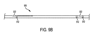
[0182] 図2は、本開示の実施形態による例示的な閉塞バルーンデバイス202の側面図である。閉塞バルーンデバイス202は、一般に、カテーテルシャフト206の遠位部分に保持される膨張可能バルーン204を含む。閉塞バルーンデバイス202は、同様に、カテーテルシャフト206の近位部分に保持される接続ハブ208を含む。接続ハブ208及びカテーテルシャフト206は、両者の間の界面において遠位テーパ付き歪軽減体210を保持する。カテーテルシャフト206は、同様に、1つ又は複数のX線不透過性マーカ212を保持し、それにより、閉塞バルーンデバイス202の位置は、医療撮像によって(例えば、X線透視によって)決定される。カテーテルシャフト206は、例えば、図2に示す3つのX線不透過性マーカ212を保持する。第1のX線不透過性マーカ212は、膨張可能バルーン204の近位部分と軸方向に整列し、第2のX線不透過性マーカ212は、膨張可能バルーン204の中間部分と軸方向に整列し、第3のX線不透過性マーカ212は、膨張可能バルーン204の遠位部分と軸方向に整列する。
[0182] FIG. 2 is a side view of an exemplary
[0183] 図3は、図2の閉塞バルーンデバイス202の膨張可能バルーン204の側面図であり、図3において、膨張可能バルーン204は膨張状態で示される。膨張可能バルーン204は、壁302、膨張チャンバ304、全長305、長さ310を有する近位ネック306、長さ328を有する遠位ネック324、長さ320を有する作業部分316、近位ネック306と作業部分316との間に配設される近位テーパ付き部分312、及び遠位ネック324と作業部分316との間に配設される遠位テーパ付き部分322を含む。
[0183] FIG. 3 is a side view of the
[0184] 膨張可能バルーン204の壁302は、膨張チャンバ304を画定する。膨張チャンバ304は、バルーンを膨張させる膨張流体(例えば、約80パーセント(すなわち、80パーセント±5パーセント)生理食塩水及び約20パーセント(すなわち、20パーセント±5パーセント)造影溶液)を受取るように適合される。臨床医がリード線取外しカテーテル104を血管系に導入し、膨張可能バルーン204を穿孔108に隣接して位置決めし、膨張可能バルーンを膨張させると、膨張可能バルーン204は、穿孔108の閉塞を促進する。
[0184] The
[0185] 幾つかの実施形態において、膨張可能バルーン204は、1つ又は複数の比較的柔軟な材料で形成される。こうした材料は、比較的高い拡張力を血管に与えることなく、異なる直径の血管、不規則性を有する血管、及び/又は、埋め込み式物体(心臓リード線等)を保持する血管を充填することを促進する。膨張可能バルーン204は、ポリウレタン等の1つ又は複数のエラストマー材料で形成される。例えば、膨張可能バルーン204は、オハイオ州ウィクリフ(Wickliffe,Ohio)のThe Lubrizol Corporationから入手可能であるPellethane(登録商標)、特に80AE Pellethane(登録商標)で形成される。膨張可能バルーン204は、約85A(すなわち、85A±4A)のショアAデュロメータを有する。
[0185] In some embodiments, the
[0186] 膨張可能バルーン204は、約98mm(すなわち、98mm±3mm)から約82mm(すなわち、82mm±3mm)の全長305を有する。
[0186] The
[0187] 膨張可能バルーン204は、(1つ又は複数の接着剤、圧縮フィット、又は同様なものによって)カテーテルシャフト206に係合する近位ネック306を含む。近位ネック306は、約2.5mm(すなわち、2.5mm±0.07mm)の内径308を有する。近位ネック306は、約10mm(すなわち、10mm±1mm)の長さ310を有する。近位ネック306は、約0.24mm(すなわち、0.24mm±0.01mm)の壁厚を有する。
[0187] The
[0188] 近位ネック306の遠位で、近位ネック306は、近位テーパ付き部分312に結合する。近位テーパ付き部分312は、約0.036mm(すなわち、0.036mm±0.0064mm)、約0.041mm(すなわち、0.041mm±0.0064mm)、約0.046mm(すなわち、0.046mm±0.0064mm)、又は約0.051mm(すなわち、0.051mm±0.0064mm)の壁厚を有する。膨張可能バルーン204が膨張すると、近位テーパ付き部分312は、膨張可能バルーン204の長手方向軸314に対して約45度(すなわち、45度±10度)の角度313で配設される。
[0188] Distal to the proximal neck 306, the proximal neck 306 couples to the proximal
[0189] 近位テーパ付き部分312の遠位で、近位テーパ付き部分312は、作業部分316に結合する。作業部分316は、膨張可能バルーン204が適切に位置決めされ膨張されると穿孔108を閉塞させる。作業部分316は、約20mm(すなわち、20mm±2mm)より大きい、例えば、約20mm(すなわち、20mm±2mm)と約30mm(すなわち、30mm±2mm)との間の、またおそらくは、約20mm(すなわち、20mm±2mm)と約25mm(すなわち、25mm±2mm)との間の膨張外径318を有する。作業部分316は、約80mm(すなわち、80mm±3mm)〜約65mm(すなわち、65mm±3mm)の長さ320を有する。作業部分316は、約0.036mm(すなわち、0.036mm±0.0064mm)、約0.041mm(すなわち、0.041mm±0.0064mm)、約0.046mm(すなわち、0.046mm±0.0064mm)、又は約0.051mm(すなわち、0.051mm±0.0064mm)の壁厚を有する。したがって、膨張状態における作業部分316の長さ320と膨張可能バルーン204の外径318との比は、約2.6:1〜約4:1である。約80mm〜約65mmの長さ320について約20mm〜約25mmの比較的一定の膨張外径318であるこの比を有することは、膨張可能バルーン204が、患者血管系内で穿孔108に隣接して留置され膨張されると穿孔108を閉塞する可能性を増加させる。すなわち、膨張可能バルーン204の作業部分316の長さ320は、穿孔108より大幅に長くなるように設計され、それにより、穿孔を迅速に位置特定し閉塞させる臨床医の能力をおそらくは増加させる。
[0189] Distal to proximal tapered
[0190] 先に述べたように、膨張可能バルーン204の作業部分316は、約20mm(すなわち、20mm±2mm)より大きい、例えば、約20mm(すなわち、20mm±2mm)と約30mm(すなわち、30mm±2mm)との間の、またおそらくは、約20mm(すなわち、20mm±2mm)と約25mm(すなわち、25mm±2mm)との間の膨張外径318を有する。膨張可能バルーン204の作業部分316の外径318をこの直径まで膨張させることは、膨張可能バルーン204の作業部分316が、穿孔108における血管102の直径とほぼ同じ直径である又はそれよりわずかに大きいことになる可能性を増加させる。膨張可能バルーン204の作業部分316の外径318を穿孔108における血管102の直径とほぼ同じ直径になる又はそれよりわずかに大きくなるように膨張させることは、膨張可能バルーン204が、穿孔108をそのサイズを増加させることなく閉鎖することになる可能性を増加させる。
[0190] As mentioned above, the working portion 316 of the
[0191] また、膨張可能バルーン204は、ポリウレタン等の1つ又は複数のエラストマー材料で形成される。膨張可能バルーン204を、先に参照した範囲の直径まで膨張させるため、膨張可能バルーン204を膨張流体で約0psi〜約3psiのバルーン膨張チャンバ304内の圧力まで膨張させることが同様に望ましい。膨張可能バルーン204をこうした圧力まで及び/又は所望の直径に膨張させるために使用される膨張流体の量は、約20ml(cc)〜約60ml(cc)である。
[0191] The
[0192] 作業部分316の遠位で、作業部分316は、遠位テーパ付き部分322に結合する。遠位テーパ付き部分322は、約0.036mm(すなわち、0.036mm±0.0064mm)、約0.041mm(すなわち、0.041mm±0.0064mm)、約0.046mm(すなわち、0.046mm±0.0064mm)、又は約0.051mm(すなわち、0.051mm±0.0064mm)の壁厚を有する。膨張可能バルーン204が膨張すると、遠位テーパ付き部分322は、長手方向軸314に対して約45度(すなわち、45度±10度)の角度323で配設される。
[0192] Distal to working portion 316, working portion 316 couples to distal tapered
[0193] 遠位テーパ付き部分322の遠位で、遠位テーパ付き部分322は、(1つ又は複数の接着剤、圧縮フィット、又は同様なものによって)カテーテルシャフト206に係合する遠位ネック324に結合する。遠位ネック324は、約2.5mm(すなわち、2.5mm±0.07mm)の内径326を有する。遠位ネック324は、約10mm(すなわち、10mm±1mm)の長さ328を有する。遠位ネック324は、約0.24mm(すなわち、0.24mm±0.01mm)の壁厚を有する。
[0193] Distal to the distal tapered
[0194] 図4は、上述したカテーテルシャフト206として使用されるカテーテルシャフト402の第1の例示的な実施形態の断面図である。カテーテルシャフト402は、ポリウレタン等の1つ又は複数のエラストマー材料で形成される。例えば、カテーテルシャフト402は、The Lubrizol Corporationから入手可能であるPellethane(登録商標)、特に75D Pellethane(登録商標)で形成される。
[0194] FIG. 4 is a cross-sectional view of a first exemplary embodiment of a
[0195] カテーテルシャフト402は、約2.1mm(すなわち、2.1mm±0.038mm)の外径403を有する。カテーテルシャフト402は、約110cmm(すなわち、110cm±0.3cm)の長さを有する。
[0195] The
[0196] カテーテルシャフト402は、第1の管腔404を含み、第1の管腔404は、閉塞バルーンデバイス202を穿孔108に近接する位置まで誘導するガイドワイヤ又は埋め込み式心臓リード線を受取るように適合される。したがって、第1の管腔404は、同様に、ガイドワイヤ管腔又は埋め込み式リード線管腔と呼ばれる。第1の管腔404は、カテーテルシャフト402の外径403に対して非同心に配設される。第1の管腔404がガイドワイヤを受取るように適合されると仮定すると、第1の管腔404は、円形断面を有し、約0.94mm(すなわち、0.94mm±0.025mm)の直径を有する。やはり、第1の管腔404がガイドワイヤを受取るように適合されると仮定すると、第1の管腔404と外径403との間の最小壁厚405は、約0.15mm(すなわち、0.15mm±0.025mm)である。しかし、第1の管腔404が埋め込み式心臓リード線を受取るように適合される場合、第1の管腔404は、心臓リード線の直径が、通常、0.25mmより大きいため、より大きな円形断面を有する。したがって、第1の管腔404は、0.25mmより大きい円形断面を有する。同様に、第1の管腔404が円形断面を有するものとして示されるが、第1の管腔404の断面形状は、長円形等の非円形断面を有する。
[0196]
[0197] カテーテルシャフト402は、同様に、接続ハブ208から膨張流体を受取り、膨張流体をバルーン膨張チャンバ304に送出するように適合される第2の管腔406を含む。したがって、第2の管腔406は、同様に、膨張管腔と呼ばれる。第2の管腔406は、第1の管腔404及びカテーテルシャフト402の外径403に対して非同心に配設される。第2の管腔406は、円形断面形状又は三日月様の断面形状等の非円形断面形状を有する。第2の管腔406が三日月様の断面形状を有すると仮定すると、第2の管腔406は、約1.8mm(すなわち、1.8mm±0.025mm)の幅408を有する。第2の管腔406は、約0.76mm(すなわち、0.76mm±0.025mm)の、カテーテルシャフト402を2分する平面内の高さ410を有する。膨張可能バルーンをできる限り迅速に膨張させ、穿孔を通る考えられる血液喪失を最小にするため、できる限り多くの膨張流体を、第2の管腔406を通り、膨張可能バルーンの膨張チャンバ内に出来る限り迅速に導入することが望ましい。したがって、カテーテルシャフト402の所与の外径403について第2の管腔406用の出来る限り大きな断面積を有することが望ましい。例えば、2.1mm(すなわち、2.1mm±0.038mm)の外径403から2.3mm(すなわち、2.3mm±0.038mm)の外径の場合、第2の管腔406用の断面積は、0.65mm2と1.90mm2との間、又は、両者の間の0.01mm2の任意の増分、例えば、0.66、0.67、0.68、0.69、0.70、…1.0…1.5…1.9mm2である。
[0197]
[0198] 第2の管腔406と第1の管腔404との間の最小壁厚412は、約0.1mm(すなわち、0.1mm±0.025mm)である。第2の管腔406と外径403との間の最小壁厚414は、約0.15mm(すなわち、0.15mm±0.025mm)である。以下の2つ以上を有することは、臨床医が、膨張流体によって膨張可能バルーン204の膨張チャンバ304を迅速に膨張させることを可能にする。以下とは、第2の管腔406用の三日月様の断面形状;第1の管腔404と外径403との間の壁厚405、約0.15mm;第2の管腔406と外径403との間の壁厚414、約0.15mm;及び、第2の管腔406と第1の管腔404との間の壁厚412、約0.1mmである。
[0198] The
[0199] カテーテルシャフト402は、同様に、第2の管腔406をカテーテルシャフト402の外部及びバルーン膨張チャンバ304に結合する1つ又は複数のアパーチャ(図示せず)を含む。すなわち、第2の管腔406は、1つ又は複数のアパーチャを介して膨張可能バルーン204に膨張流体を送出する。第2の管腔406は、(例えば、別個のカバー、カテーテルシャフト402の壁、又は同様なものによって)カテーテルシャフト402の遠位端で覆われる。
[0199]
[0200] 図5は、上述したカテーテルシャフト206として使用されるカテーテルシャフト502の第2の例示的な実施形態の断面図である。カテーテルシャフト502は、ポリウレタン等の1つ又は複数のエラストマー材料で形成される。例えば、カテーテルシャフト502は、The Lubrizol Corporationから入手可能であるPellethane(登録商標)、特に75D Pellethane(登録商標)で形成される。
[0200] FIG. 5 is a cross-sectional view of a second exemplary embodiment of a
[0201] カテーテルシャフト502は、約2.3mm(すなわち、2.3mm±0.038mm)の外径503を有する。カテーテルシャフト502は、約110cmm(すなわち、110cm±0.3cm)の長さを有する。
[0201] The
[0202] カテーテルシャフト502は、第1の管腔504を含み、第1の管腔504は、閉塞バルーンデバイス202を穿孔108に近接する位置まで誘導するガイドワイヤ又は埋め込み式心臓リード線を受取るように適合される。第1の管腔504は、カテーテルシャフト502の外径503に対して非同心に配設される。第1の管腔504は、円形断面を有し、約0.94mm(すなわち、0.94mm±0.025mm)の直径を有する。第1の管腔504と外径503との間の最小壁厚505は、約0.1mm(すなわち、0.1mm±0.025mm)である。
[0202]
[0203] カテーテルシャフト502は、同様に、接続ハブ208から膨張流体を受取り、膨張流体をバルーン膨張チャンバ304に送出するように適合される第2の管腔506を含む。第2の管腔506は、第1の管腔504及びカテーテルシャフト502の外径503に対して非同心に配設される。第2の管腔506は、三日月様の断面形状等の非円形断面形状を有する。第2の管腔506は、約2.0mm(すなわち、2.0mm±0.025mm)の幅508を有する。第2の管腔506は、約0.94mm(すなわち、0.94mm±0.025mm)の、カテーテルシャフト502を2分する平面内の高さ510を有する。第2の管腔506と第1の管腔504との間の最小壁厚512は、約0.1mm(すなわち、0.1mm±0.025mm)である。第2の管腔506と外径503との間の最小壁厚514は、約0.15mm(すなわち、0.15mm±0.025mm)である。以下の2つ以上を有することは、臨床医が、膨張流体によって膨張可能バルーン204の膨張チャンバ304を迅速に膨張させることを可能にする。以下とは、第2の管腔506用の三日月様の断面形状;第1の管腔504と外径503との間の壁厚505、約0.15mm;第2の管腔506と外径503との間の壁厚514、約0.15mm;及び、第2の管腔506と第1の管腔504との間の壁厚512、約0.1mmである。
[0203]
[0204] カテーテルシャフト502は、同様に、第2の管腔506をカテーテルシャフト502の外部及びバルーン膨張チャンバ304に結合する1つ又は複数のアパーチャ(図示せず)を含む。すなわち、第2の管腔506は、1つ又は複数のアパーチャを介して膨張可能バルーン204に膨張流体を送出する。第2の管腔506は、(例えば、別個のカバー、カテーテルシャフト502の壁、又は同様なものによって)カテーテルシャフト502の遠位端で覆われる。
[0204]
[0205] 幾つかの実施形態において、膨張可能バルーン204、カテーテルシャフト402、及びカテーテルシャフト502の寸法及び材料特性は、比較的小さなガイドワイヤ及びイントロデューサシースを有する閉塞バルーンデバイス202を使用し、膨張流体を膨張可能バルーン204に比較的迅速に(例えば、15秒以下で)送出することを促進する。更に、閉塞バルーンデバイス202は、対象者の血管系に入り、血管穿孔を閉塞させるのに十分な強度を有する。
[0205] In some embodiments, the dimensions and material properties of the
[0206] 図6A及び図6Bは、上述したX線不透過性マーカ212として使用されるX線不透過性マーカバンド602の図である。X線不透過性マーカバンド602は、約90パーセント(すなわち、90パーセント±1パーセント)プラチナ及び約10パーセント(すなわち、10パーセント±1パーセント)イリジウムの混合物等の1つ又は複数のX線不透過性材料で形成される。X線不透過性マーカバンド602は、カテーテルシャフト206の外周の周りに延在するように適合される開口端付き円筒形状を有する。X線不透過性マーカバンド602は、約2.3mm(すなわち、2.3mm±0.01mm)〜約2.5mm(すなわち、2.5mm±0.01mm)の範囲内の外径604を有する。X線不透過性マーカバンド602は、約2.2mm(すなわち、2.2mm±0.01mm)〜約2.4mm(すなわち、2.4mm±0.01mm)の内径606を有する。X線不透過性マーカバンド602は、約1.2mm(すなわち、1.2mm±0.05mm)の長さ608を有する。
[0206] FIGS. 6A and 6B are views of a
[0207] 図7A〜図7Dは、接続ハブ208の図である。接続ハブ208は、ポリカーボネート、特に、独国ダームスタッド(Darmstadt)のBayer Material Scienceから入手可能であるMakrolon(登録商標)等の1つ又は複数のポリマーで形成される。接続ハブ208は、分岐管腔を含み、分岐管腔は、次に、主管腔702及び分枝管腔704を含む(図7D参照)。分枝管腔704は、鋭角で主管腔702から延在する。主管腔702は、約2.2mm(すなわち、2.2mm±0.025mm)〜約2.4mm(すなわち、2.4mm±0.025mm)の範囲内の内径706を有する。主管腔702は、接続ハブ208の遠位側で第1のポート708に結合する。第1のポート708は、カテーテルシャフト206及び歪軽減体210に結合する。主管腔702は、接続ハブ208の近位側で第2のポート710に結合する。例えばISO594適合ルアーコネクタである第2のポート710は、ガイドワイヤを受取る、及び/又は、シリンジ等の膨張流体源に結合するように適合される。分枝管腔704は、接続ハブ208の近位側で第3のポート712に結合する。例えばISO594適合ルアーコネクタである第3のポート712は、ガイドワイヤを受取る、及び/又は、シリンジ等の膨張流体源に結合するように適合される。
[0207] FIGS. 7A to 7D are diagrams of the
[0208] 図8Aは、本開示の実施形態による血管内の穿孔を閉塞させるための例示的な方法を示す。方法は、上述した図2〜図7に示す閉塞バルーンデバイス202等の閉塞バルーンデバイス、又は、以下で述べる図9〜図22に示す閉塞バルーンデバイス等の閉塞バルーンデバイスの任意のものを提供することによるブロック802にて始まる。簡単にするため、この段落は、閉塞バルーンデバイス202の特徴を参照するだけである。ブロック804にて、カテーテルシャフト206及び膨張可能バルーン204は、膨張可能バルーン204が、図8Bに示すように、穿孔に近接して位置決めされるまで、血管内で進行される。引き続き図8Bを参照すると、膨張可能バルーン204は、穿孔108に隣接して、したがって、穿孔108に近接して膨張状態にある。膨張可能バルーン204は穿孔108全体に隣接しそれを覆うものとして図8Bに示されるが、閉塞バルーンデバイス202は、膨張可能バルーン204が穿孔108の一部分だけを覆うように、又は、膨張可能バルーン204が穿孔108の部分を全く覆わないが、血管内の血流の上流にある場所で穿孔108の非常に近くに配設されるように血管102内の位置に留置され、それにより、膨張可能バルーン204が、穿孔108を通して流れる血流を閉塞させることを可能にする。
[0208] FIG. 8A illustrates an exemplary method for occluding a perforation in a blood vessel according to an embodiment of the present disclosure. The method provides any of an occlusion balloon device, such as the
[0209] やはり図8Aを参照すると、幾つかの実施形態において、カテーテルシャフト206の第1の管腔404は、ガイドワイヤ又は埋め込み式心臓リード線を受取り、カテーテルシャフト206及び膨張可能バルーン204は、ガイドワイヤ又は埋め込み式心臓リード線に沿って進行される。幾つかの実施形態において、カテーテルシャフト206は、大腿イントロデューサシース(例えば、12F大腿イントロデューサシース)を使用することによって大腿静脈(例えば、右大腿静脈)を介して穿孔まで進行される。幾つかの実施形態において、カテーテルシャフト206は、近位X線不透過性マーカ212が上大静脈と右心房の接合部に位置するまで進行される。ブロック806にて、膨張流体(例えば、上述した生理食塩水及び造影溶液)は、カテーテルシャフト206の第2の管腔406を介して膨張可能バルーン204に送出されて、膨張可能バルーン204を膨張させ、それにより、穿孔を閉塞させる。幾つかの実施形態において、60ml(cc)シリンジは、バルーン204が血管系に一致するまで、膨張可能バルーン204に膨張流体を送出する。幾つかの実施形態において、膨張流体は、約2気圧(すなわち、2気圧±10パーセント)〜約3気圧(すなわち、3気圧±10パーセント)の範囲内の圧力で膨張可能バルーン204に送出される。幾つかの実施形態において、造影剤は、上静脈アクセス部位を介して注入されて、バルーン204の適切な膨張及び穿孔の閉塞を確認する。幾つかの実施形態において、患者の血行動態徴候及び/又は生命徴候の安定化は、穿孔の閉塞を確認するために使用される。幾つかの実施形態において、また、ブロック808にて、方法は、任意選択で、血管穿孔を覆って膨張可能バルーン204から閉塞パッチ(例えば、以下で述べる閉塞パッチ1708)を配備することを含み、それにより、穿孔を閉塞させる。そして、膨張可能バルーン204が閉塞パッチを含む場合、バルーン204の膨張は、閉塞パッチの配備を引起す。更に、幾つかの実施形態において、また、ブロック810にて、方法は、任意選択で、血管系内でパッチの位置を維持するため血管系に閉塞パッチを結合させることを含む。幾つかの実施形態において、血管系に閉塞パッチを結合させることは、以下で述べるやり方の任意のやり方でパッチによって保持される1つ又は複数の接着剤を活性化することを含む。幾つかの実施形態において、閉塞がもはや必要とされないとき、バルーン204は、60ml(cc)シリンジを使用することによって第2の管腔406に吸引を加えることによって収縮する。幾つかの実施形態において、バルーン204の収縮は、X線透視を使用することによって確認される。
[0209] Still referring to FIG. 8A, in some embodiments, the
[0210] 図9A及び図9Bは、本開示の実施形態による別の例示的な閉塞バルーンデバイス902の遠位部分の側面図である。閉塞バルーンデバイス902は、一般に、上述したバルーンと同様である膨張可能バルーン904を含む。膨張可能バルーン904は、カテーテルシャフト906の遠位部分で保持される。閉塞バルーンデバイス902は、同様に、上述した接続ハブと同様である接続ハブ(図示せず)を含む。接続ハブは、カテーテルシャフト906の近位部分で保持される。接続ハブ及びカテーテルシャフト906は、両者の間の界面において、上述した歪軽減体と同様である遠位テーパ付き歪軽減体(図示せず)を保持する。カテーテルシャフト906は、同様に、1つ又は複数のX線不透過性マーカ912を保持し、それにより、閉塞バルーンデバイス902の位置は、医療撮像によって(例えば、X線透視によって)決定される。カテーテルシャフト906は、例えば、図9A及び図9Bに示すように3つのX線不透過性マーカ912を保持する。第1のX線不透過性マーカ912は、バルーン904の近位ネック914及びバルーン904の近位テーパ付き部分916の交差部と軸方向に整列する。第2のX線不透過性マーカ912は、バルーン904の近位テーパ付き部分916及び作業部分918の交差部に軸方向に整列する。第3のX線不透過性マーカ912は、バルーン904の作業部分918及び遠位テーパ付き部分920の交差部と軸方向に整列する。
[0210] FIGS. 9A and 9B are side views of a distal portion of another exemplary
[0211] 本開示の膨張可能バルーンは、穿孔部位の処置を支援するため、種々の医薬品及び生物製剤で処置又はコーティングされ得る。幾つかの実施形態において、本開示の膨張可能バルーンは、止血組成物でコーティングされて、血流喪失のレートを減少させ、穿孔部位の外科的修復を計画し始動するためのより多くの時間を可能にし得る。一般に、止血組成物は、1つ又は複数の止血用血液凝固剤(同様に、止血剤又は凝固剤と呼ばれる)を含む。適した凝固剤は、止血を刺激又は促進する有効な量が止血組成物中に含まれている。適した凝固剤は、フィブリノーゲンをフィブリンに変換するトロンビン又は任意の自然発生的又は合成作用物質;カルシウム、ナトリウム、マグネシウム、又は止血を促進する他の化学イオン;プロタミン硫酸塩;イプシロンアミノカプロン酸、フィブリノーゲン、キチン、及び同様なものを含むが、それに限定されない。本開示の止血組成物の一部として使用され得る止血剤は、同様に、フィブリンシーラント等のフィブリンベース剤(同様にフィブリン接着剤と呼ばれる)、ゼラチンマトリクストロンビン、ゼラチンスポンジ、酸化セルロース、コラーゲンスポンジ、コラーゲンフリース、遺伝子組換え第VIIa因子を含むが、それに限定されない。 [0211] The inflatable balloons of the present disclosure can be treated or coated with a variety of pharmaceuticals and biologics to aid in the treatment of perforation sites. In some embodiments, the inflatable balloons of the present disclosure are coated with a hemostatic composition to reduce the rate of blood flow loss and allow more time to plan and initiate surgical repair of a perforation site. May enable. Generally, the hemostatic composition comprises one or more hemostatic coagulants (also referred to as hemostatics or coagulants). A suitable coagulant is included in the hemostatic composition in an amount effective to stimulate or promote hemostasis. Suitable coagulants include thrombin or any naturally occurring or synthetic agent that converts fibrinogen to fibrin; calcium, sodium, magnesium, or other chemical ion that promotes hemostasis; protamine sulfate; epsilon aminocaproic acid, fibrinogen, Includes but is not limited to chitin, and the like. Hemostatic agents that can be used as part of the hemostatic compositions of the present disclosure also include fibrin-based agents such as fibrin sealants (also called fibrin glue), gelatin matrix thrombin, gelatin sponge, oxidized cellulose, collagen sponge, Includes, but is not limited to, collagen fleece, recombinant Factor VIIa.
[0212] 幾つかの実施形態において、限定はしないが、ポリエチレングリコール、シアノアクリレート、フィブロネクチン、フォンビルブランド因子、プロテインZ、及び同様なものを含む、細胞又は組織付着特性を有する1つ又は複数の作用物質を止血組成物内に含むことが同様に有利である。細胞又は組織付着特性を有する作用物質は、更に、血管穿孔からの血流喪失のレートを減少させると共に、穿孔創傷部位の治癒を促進し得る。血管系を通り穿孔部位までバルーンが走行するときに組成物を安定させるため及び/又は組成物の早期喪失を防止するため、生体適合性ポリマーの添加が有る状態で又は無い状態で、限定はしないが、ノルジヒドログアイヤレチン酸、レスベラトロール、プロピルガラート、及び同様なもの等のリポフィリック抗酸化物質を含む1つ又は複数のコーティング剤を止血組成物内に含むことが同様に有利である。 [0212] In some embodiments, one or more having cell or tissue adhesion properties, including but not limited to polyethylene glycol, cyanoacrylate, fibronectin, von Willebrand factor, protein Z, and the like. It is likewise advantageous to include the agent in a hemostatic composition. Agents with cell or tissue attachment properties may further reduce the rate of blood flow loss from vascular perforations and promote healing of perforated wound sites. Without or with the addition of biocompatible polymers to stabilize the composition as the balloon travels through the vasculature to the site of perforation and/or to prevent premature loss of the composition. It is also advantageous to include in the hemostatic composition one or more coating agents that include lipophyllic antioxidants such as nordihydroguaiaretic acid, resveratrol, propyl gallate, and the like. is there.
[0213] 止血組成物の他の成分は、創傷治癒を促進する成長因子又は他の治療剤等のホルモン剤を含み得る。幾つかの実施形態において、止血組成物は、ポテンシャル反応性表面ヒドロキシル基を有するシリカナノ粒子の創傷シーラント組成物及び/又は架橋結合剤、並びに、おそらくは、例えば、流体除去剤、脱水剤、接着性クランプ剤、膨潤剤、ナノ粒子又はマイクロ粒子等の薬物送出担体、凝塊増大組成物、賦活剤又は促進剤、及び同様なものを含む更なる組成物を含む。他の実施形態において、止血組成物は、ペニシリン、ペニシリン合剤、スルホンアミド、リンコサミド、カルバペネム、テトラサイクリン、アミノグリコシド等の予防的抗菌剤及び殺菌剤並びに他の適した抗菌組成物及びその組合せを含み得る。本開示の止血組成物は、同様に、防腐剤、湿潤剤、乳化剤、及び分散剤を含む、適した補助剤及び賦形剤、単独での、又は、抗真菌薬、例えば、パラベンス、クロロブタノール、フェノール、ソルビン酸、及び同様なものと組合せた更なる抗菌剤を含み得る。砂糖、塩化ナトリウム、及び同様なもの等の浸透圧調節剤を含むことが同様に可能である。更に、モノステアリン酸アルミニウム及びゼラチン等の吸収を遅延させるための作用物質が、止血組成物内に同様に含まれ得る。本開示に基づいて当業者が容易に認識するように、止血組成物は、穿孔部位に直接塗布され得る、粉末、スプレー、エーロゾル、発泡体、又はゲルであるように調製され得る。 [0213] Other components of the hemostatic composition may include hormonal agents such as growth factors or other therapeutic agents that promote wound healing. In some embodiments, the hemostatic composition comprises a silica nanoparticle wound sealant composition and/or crosslinker having potential reactive surface hydroxyl groups, and possibly, for example, a fluid remover, a dehydrating agent, an adhesive clamp. Further compositions including agents, swelling agents, drug delivery carriers such as nanoparticles or microparticles, clot enhancing compositions, activators or enhancers, and the like. In other embodiments, the hemostatic composition may include prophylactic and antiseptic agents such as penicillins, penicillin combinations, sulfonamides, lincosamides, carbapenems, tetracyclines, aminoglycosides and other suitable antimicrobial compositions and combinations thereof. . The hemostatic compositions of the present disclosure also include suitable adjuvants and excipients, including preservatives, wetting agents, emulsifying agents, and dispersing agents, alone or with antifungal agents such as parabens, chlorobutanol. , Phenol, sorbic acid, and the like in combination with additional antimicrobial agents. It is likewise possible to include osmolality adjusting agents such as sugar, sodium chloride, and the like. In addition, agents to delay absorption such as aluminum monostearate and gelatin may be included within the hemostatic composition as well. As one of ordinary skill in the art will readily appreciate based on the present disclosure, the hemostatic composition can be prepared to be a powder, spray, aerosol, foam, or gel that can be applied directly to the puncture site.
[0214] 本開示の止血組成物は、種々のやり方で穿孔部位の組織に送出され得る。例えば、止血組成物は、カテーテルの遠位端に位置決めされる膨張可能バルーンの外周に塗布され、それにより、穿孔を閉塞させるためにバルーンが膨張すると、止血組成物は、穿孔部位の組織と接触させられる。穿孔部位の組織に送出されると、止血組成物の異なる成分は、血液凝固の促進及び/又は細胞及び組織付着等のその生物学的作用を施行して、血流喪失レートを減少させ、穿孔部位の治癒を促進し得る。幾つかの実施形態において、組成物は、膨張可能バルーンの折畳み体(fold)(その未膨張状態にある)に塗布され、それにより、カテーテルの遠位端が血管系内に位置決めされているときに、組成物が、早期喪失から保護される。バルーンが配備されると、組成物は、露出され、穿孔部位の組織に送出され得る。 [0214] The hemostatic compositions of the present disclosure can be delivered to the tissue at the perforation site in a variety of ways. For example, the hemostatic composition is applied to the outer circumference of an inflatable balloon positioned at the distal end of the catheter such that when the balloon is inflated to occlude the perforation, the hemostatic composition contacts the tissue at the perforation site. To be made. Once delivered to the tissue at the perforation site, the different components of the hemostatic composition may perform their biological effects such as promoting blood coagulation and/or cell and tissue attachment to reduce blood flow loss rates and perforation. It may promote healing of the site. In some embodiments, the composition is applied to the fold of the expandable balloon (in its unexpanded state) such that the distal end of the catheter is positioned within the vasculature. In addition, the composition is protected from premature loss. Upon deployment of the balloon, the composition may be exposed and delivered to the tissue at the site of the puncture.
[0215] 他の実施形態において、穿孔部位の組織に対する組成物の排出を促進するデバイス及び機構が、バルーンに隣接してカテーテルの遠位端に含まれ得る。例えば、1つ又は複数の光ファイバが使用されて、膨張可能バルーン内に含まれる液体媒体(例えば、造影媒体)に対して光エネルギーのパルスを送出し、それにより、半径方向に伝搬し、組成物を穿孔部位の組織に送出するショック波(例えば、液体媒体のキャビテーション)を生成し得る。本開示に基づいて当業者が認識するように、穿孔部位の組織に止血組成物を送出するための他の手段が同様に使用され得る。 [0215] In other embodiments, devices and mechanisms that facilitate ejection of the composition to the tissue at the puncture site may be included at the distal end of the catheter adjacent the balloon. For example, one or more optical fibers may be used to deliver a pulse of light energy to a liquid medium (eg, a contrast medium) contained within an inflatable balloon, thereby causing radial propagation and composition. A shock wave (eg, cavitation of a liquid medium) can be generated that delivers an object to the tissue at the site of perforation. As will be appreciated by one of skill in the art based on the present disclosure, other means for delivering the hemostatic composition to the tissue at the perforation site may be used as well.
[0216] カテーテルシャフト906は、上述した、それぞれ第1及び第2の管腔と同様である第1及び第2の管腔(図示せず)を含む。カテーテルシャフト906は、同様に、第2の管腔を、カテーテルシャフト906及びバルーン膨張チャンバ924の外部に結合させる1つ又は複数のアパーチャ922を含む。すなわち、第2の管腔は、1つ又は複数のアパーチャ922を介して膨張流体を膨張可能バルーン904に送出する。カテーテルシャフト906は、図9A及び図9Bに示すように、例えば、2つのアパーチャ922を含む。第1のアパーチャ922は、バルーン904の近位テーパ付き部分916と軸方向に整列する。第2のアパーチャ922は、バルーン904の遠位テーパ付き部分920と軸方向に整列する。
[0216]
[0217] カテーテルシャフト906の遠位端は、カテーテルシャフト906の第2の管腔を覆う遠位先端926を保持する。遠位先端926は、カテーテルシャフト906の第1の管腔と整列する開口(図示せず)を含む。第1の管腔と共に、開口は、ガイドワイヤ又は埋め込み式心臓リード線を受取るように適合される。遠位先端926は、ポリウレタン等の1つ又は複数のエラストマー材料で形成される。例えば、遠位先端926は、The Lubrizol Corporationから入手可能であるPellethane(登録商標)、特に65D Pellethane(登録商標)で形成される。
[0217] The distal end of the
[0218] 図10は、本開示の実施形態による別の例示的な閉塞バルーンデバイス1002の側面図である。閉塞バルーンデバイス1002は、一般に、カテーテルシャフト1006の遠位部分で保持される膨張可能バルーン1004を含む。閉塞バルーンデバイス1002は、同様に、カテーテルシャフト1006の近位部分で保持される接続ハブ1008を含む。接続ハブ1008及びカテーテルシャフト1006は、両者の界面において遠位テーパ付き歪軽減体1010を保持する。カテーテルシャフト1006は、同様に、1つ又は複数のX線不透過性マーカ1012を保持し、それにより、閉塞バルーンデバイス1002の位置は、医療撮像によって(例えば、X線透視によって)決定される。カテーテルシャフト1006は、例えば、図10に示す3つのX線不透過性マーカ1012を保持する。第1のX線不透過性マーカ1012は、膨張可能バルーン1004の近位部分と軸方向に整列し、第2のX線不透過性マーカ1012は、膨張可能バルーン1004の中間部分と軸方向に整列し、第3のX線不透過性マーカ1012は、膨張可能バルーン1004の遠位部分と軸方向に整列する。
[0218] FIG. 10 is a side view of another exemplary
[0219] 図11A及び図11Bは、それぞれ、図10の閉塞バルーンデバイス1002の膨張可能バルーン1004の部分縦断面図及び正面図であり、膨張可能バルーン1004は膨張状態で示される。膨張可能バルーン1004は、壁1102、膨張チャンバ1104、長さ1110を有する近位ネック1106、長さ1128を有する遠位ネック1124、長さ1120を有する作業部分1116、近位ネック1106と作業部分1116との間に配設される近位テーパ付き部分1112、及び遠位ネック1124と作業部分1116との間に配設される遠位テーパ付き部分1122を含む。
[0219] FIGS. 11A and 11B are a partial longitudinal cross-sectional view and a front view, respectively, of the
[0220] 膨張可能バルーン1004の壁1102は、膨張チャンバ1104を画定する。膨張チャンバ1104は、バルーンを膨張させる膨張流体(例えば、約80パーセント(すなわち、80パーセント±5パーセント)生理食塩水及び約20パーセント(すなわち、20パーセント±5パーセント)造影溶液)を受取るように適合される。臨床医が閉塞バルーンデバイス1002を血管系に導入し、膨張可能バルーン1004を穿孔108に隣接して位置決めし、膨張可能バルーンを膨張させると、膨張可能バルーン1004は、穿孔108の閉塞を促進する。
[0220] The
[0221] 幾つかの実施形態において、膨張可能バルーン1004は、1つ又は複数の比較的柔軟な材料で形成される。こうした材料は、比較的高い拡張力を血管に与えることなく、異なる直径の血管、不規則性を有する血管、及び/又は、埋め込み式物体(心臓リード線等)を保持する血管を充填することを促進する。膨張可能バルーン1004は、ポリウレタン等の1つ又は複数のエラストマー材料で形成される。例えば、膨張可能バルーン1004は、The Lubrizol Corporationから入手可能であるPellethane(登録商標)、特に80AE Pellethane(登録商標)で形成される。膨張可能バルーン1004は、約85A(すなわち、85A±4A)のショアAデュロメータを有する。
[0221] In some embodiments, the
[0222] 近位ネック1106は、1つ又は複数の接着剤、圧縮フィット、又は同様なものによってカテーテルシャフト1006に係合する。近位ネック1106は、約2.5mm(すなわち、2.5mm±0.07mm)の内径1108を有する。近位ネック1106は、約10mm(すなわち、10mm±1mm)の長さ1110を有する。近位ネック1106は、約0.24mm(すなわち、0.24mm±0.01mm)の壁厚を有する。
[0222] The
[0223] 近位ネック1106の遠位で、近位ネック1106は、近位テーパ付き部分1112に結合する。近位テーパ付き部分1112は、約0.036mm(すなわち、0.036mm±0.0064mm)、約0.041mm(すなわち、0.041mm±0.0064mm)、約0.046mm(すなわち、0.046mm±0.0064mm)、又は約0.051mm(すなわち、0.051mm±0.0064mm)の壁厚を有する。膨張可能バルーン1004が膨張すると、近位テーパ付き部分1112は、膨張可能バルーン1004の長手方向軸1114に対して約35度(すなわち、35度±10度)の角度1113で配設される。
[0223] Distal to the
[0224] 近位テーパ付き部分1112の遠位で、近位テーパ付き部分1112は、作業部分1116に結合する。作業部分1116は、膨張可能バルーン1004が適切に位置決めされ膨張されると穿孔108を閉塞させる。作業部分1116は、約0.036mm(すなわち、0.036mm±0.0064mm)、約0.041mm(すなわち、0.041mm±0.0064mm)、約0.046mm(すなわち、0.046mm±0.0064mm)、又は約0.051mm(すなわち、0.051mm±0.0064mm)の壁厚を有する。作業部分1116は、約115mm(すなわち、115mm±3mm)〜約65mm(すなわち、65mm±3mm)の長さ1120を有する。
[0224] Distal to proximal tapered portion 1112, proximal tapered portion 1112 couples to working
[0225] 作業部分1116は、第1の外径1130(近位テーパ付き部分1112との界面における)から第2の外径1132(遠位テーパ付き部分1122との界面における)まで内側にテーパが付けられる。膨張すると、第1の外径1130は、約35mm(すなわち、35mm±2mm)より大きい、例えば、約35mm(すなわち、35mm±2mm)と約50mm(すなわち、50mm±2mm)との間、またおそらくは更に、約35mm(すなわち、35mm±2mm)と約45mm(すなわち、45mm±2mm)との間にある。膨張すると、第2の外径1132は、約16mm(すなわち、16mm±2mm)より大きい、例えば、約16mm(すなわち、16mm±2mm)と約30mm(すなわち、30mm±2mm)との間、またおそらくは更に、約16mm(すなわち、16mm±2mm)と約25mm(すなわち、25mm±2mm)との間にある。
[0225] The working
[0226] 膨張状態における作業部分1116の長さ1120と膨張可能バルーン1004の第1の外径1130との比は、したがって、約1.3:1〜約3.3:1であり、膨張状態における作業部分1116の長さ1120と膨張可能バルーン1004の第2の外径1132との比は、したがって、約2.2:1〜約7.2:1である。比較的長い作業長さについてこれらの比を有することは、右腕頭静脈及び右心房腔の上部分における又は両者の間における穿孔を閉塞させるのに特に適するバルーンを提供する。すなわち、作業部分1116の遠位部分は、右腕頭静脈の穿孔を閉塞させるのに特に適し、作業部分1116の近位部分は、心房腔の上部分の穿孔を閉塞させるのに特に適する。より一般的に、作業部分1116を上述した直径まで膨張させることは、作業部分1116が、穿孔108における血管102の直径とほぼ同じ直径である又はそれよりわずかに大きいことになる可能性を増加させる。作業部分1116を穿孔108における血管102の直径とほぼ同じ直径になる又はそれよりわずかに大きくなるように膨張させることは、膨張可能バルーン1004が、穿孔108をそのサイズを増加させることなく閉鎖することになる可能性を増加させる。
[0226] The ratio of the
[0227] 幾つかの実施形態において、また、図11A及び図11Bに示すように、作業部分は、第1の外径1130から第2の外径1132まで一定傾斜で内側にテーパが付けられる。換言すると、作業部分1116は、円錐台形状を有する。幾つかの実施形態において、作業部分は、第1の外径1130から第2の外径1132まで非一定傾斜で内側にテーパが付けられる。
[0227] In some embodiments, and as shown in FIGS. 11A and 11B, the working portion tapers inwardly at a constant slope from a first
[0228] やはり、膨張可能バルーン1004は、ポリウレタン等の1つ又は複数のエラストマー材料で形成される。膨張可能バルーン1004を、先に参照した範囲の直径まで膨張させるため、膨張可能バルーン1004を膨張流体で約0psi〜約3psiのバルーン膨張チャンバ1104内の圧力まで膨張させることが同様に望ましい。膨張可能バルーン1004をこうした圧力まで及び/又は所望の直径まで膨張させるために使用される膨張流体の量は、約20ml(cc)〜約60ml(cc)である。
[0228] Again, the
[0229] 作業部分1116の遠位で、作業部分1116は、遠位テーパ付き部分1122に結合する。遠位テーパ付き部分1122は、約0.036mm(すなわち、0.036mm±0.0064mm)、約0.041mm(すなわち、0.041mm±0.0064mm)、約0.046mm(すなわち、0.046mm±0.0064mm)、又は約0.051mm(すなわち、0.051mm±0.0064mm)の壁厚を有する。膨張可能バルーン1004が膨張すると、遠位テーパ付き部分1122は、長手方向軸1114に対して約30度(すなわち、30度±10度)の角度1123で配設される。
[0229] Distal to working
[0230] 遠位ネック1124は、1つ又は複数の接着剤、圧縮フィット、又は同様なものによってカテーテルシャフト1006に係合する。遠位ネック1124は、約2.5mm(すなわち、2.5mm±0.07mm)の内径1126を有する。遠位ネック1124は、約10mm(すなわち、10mm±1mm)の長さ1128を有する。遠位ネック1124は、約0.24mm(すなわち、0.24mm±0.01mm)の壁厚を有する。
[0230] The
[0231] カテーテルシャフト1006、接続ハブ1008、歪軽減体1010、及びX線不透過性マーカ(複数可)1012は、上述したカテーテルシャフト、接続ハブ、歪軽減体、及びX線不透過性マーカとそれぞれ同様である。
[0231] The
[0232] 図12A及び図12Bは、本開示の実施形態による別の例示的な閉塞バルーンデバイス1202の遠位部分の側面図である。閉塞バルーンデバイス1202は、一般に、上述したバルーン1004と同様である膨張可能バルーン1204を含む。膨張可能バルーン1204は、カテーテルシャフト1206の遠位部分で保持される。閉塞バルーンデバイス1202は、同様に、上述した接続ハブと同様である接続ハブ(図示せず)を含む。接続ハブは、カテーテルシャフト1206の近位部分で保持される。接続ハブ及びカテーテルシャフト1206は、両者の界面において、上述した歪軽減体と同様である遠位テーパ付き歪軽減体(図示せず)を保持する。カテーテルシャフト1206は、同様に、1つ又は複数のX線不透過性マーカ1212を保持し、それにより、閉塞バルーンデバイス1202の位置は、医療撮像によって(例えば、X線透視によって)決定される。カテーテルシャフト1206は、例えば、図12A及び図12Bに示す3つのX線不透過性マーカ1212を保持する。第1のX線不透過性マーカ1212は、バルーン1204の近位ネック1214及びバルーン1204の近位テーパ付き部分1216の交差部と軸方向に整列する。第2のX線不透過性マーカ1212は、近位テーパ付き部分1216及びバルーン1204の作業部分1218の交差部と軸方向に整列する。第3のX線不透過性マーカ1212は、作業部分1218及びバルーン1204の遠位テーパ付き部分1220の交差部と軸方向に整列する。
[0232] FIGS. 12A and 12B are side views of a distal portion of another exemplary
[0233] カテーテルシャフト1206は、上述した、それぞれ第1及び第2の管腔と同様である第1及び第2の管腔(図示せず)を含む。カテーテルシャフト1206は、同様に、第2の管腔を、カテーテルシャフト1206及びバルーン膨張チャンバ1224の外部に結合させる1つ又は複数のアパーチャ1222を含む。すなわち、第2の管腔は、1つ又は複数のアパーチャ1222を介して膨張流体を膨張可能バルーン1204に送出する。カテーテルシャフト1206は、図12A及び図12Bに示すように、例えば、2つのアパーチャ1222を含む。第1のアパーチャ1222は、バルーン1204の近位テーパ付き部分1216と軸方向に整列する。第2のアパーチャ1222は、バルーン1204の遠位テーパ付き部分1220と軸方向に整列する。
[0233]
[0234] カテーテルシャフト1206の遠位端は、カテーテルシャフト1206の第2の管腔を覆う遠位先端1226を保持する。遠位先端1226は、カテーテルシャフト1206の第1の管腔と整列する開口(図示せず)を含む。第1の管腔と共に、開口は、ガイドワイヤ又は埋め込み式心臓リード線を受取るように適合される。遠位先端1226は、ポリウレタン等の1つ又は複数のエラストマー材料で形成される。例えば、遠位先端1226は、The Lubrizol Corporationから入手可能であるPellethane(登録商標)、特に65D Pellethane(登録商標)で形成される。
[0234] The distal end of the
[0235] 閉塞バルーンデバイス1002及び1202に対する幾つかの変形及び修正が使用される。例えば、カテーテル1002又は1202が、非大腿静脈アプローチ(例えば、頚静脈アプローチ)を使用して挿入される場合、作業部分は、近位方向に進みながら内側にテーパが付けられる。
[0235] Several variations and modifications to the
[0236] 図13は、本開示の実施形態による別の例示的な閉塞バルーンデバイス1302の側面図である。閉塞バルーンデバイス1302は、一般に、カテーテルシャフト1306の遠位部分で保持される膨張可能バルーン1304を含む。閉塞バルーンデバイス1302は、同様に、カテーテルシャフト1306の近位部分で保持される接続ハブ1308を含む。接続ハブ1308及びカテーテルシャフト1306は、両者の界面において遠位テーパ付き歪軽減体1310を保持する。カテーテルシャフト1306は、同様に、1つ又は複数のX線不透過性マーカ1312を保持し、それにより、閉塞バルーンデバイス1302の位置は、医療撮像によって(例えば、X線透視によって)決定される。カテーテルシャフト1306は、例えば、図13に示す3つのX線不透過性マーカ1312を保持する。第1のX線不透過性マーカ1312は、膨張可能バルーン1304の近位部分と軸方向に整列し、第2のX線不透過性マーカ1312は、膨張可能バルーン1304の中間部分と軸方向に整列し、第3のX線不透過性マーカ1312は、膨張可能バルーン1304の遠位部分と軸方向に整列する。
[0236] FIG. 13 is a side view of another exemplary
[0237] 図14A及び図14Bは、それぞれ、図13の閉塞バルーンデバイス1302の膨張可能バルーン1304の部分縦断面図及び正面図であり、膨張可能バルーン1304は膨張状態で示される。膨張可能バルーン1304は、壁1402、膨張チャンバ1404、長さ1410を有する近位ネック1406、長さ1428を有する遠位ネック1424、長さ1420を有する複数の直径の作業部分1416、近位ネック1406と作業部分1416との間に配設される近位テーパ付き部分1412、及び遠位ネック1424と作業部分1416との間に配設される遠位テーパ付き部分1422を含む。
[0237] FIGS. 14A and 14B are partial longitudinal cross-sectional view and front view of the
[0238] 膨張可能バルーン1304の壁1402は、膨張チャンバ1404を画定する。膨張チャンバ1404は、バルーンを膨張させる膨張流体(例えば、約80パーセント(すなわち、80パーセント±5パーセント)生理食塩水及び約20パーセント(すなわち、20パーセント±5パーセント)造影溶液)を受取るように適合される。臨床医が閉塞バルーンデバイス1302を血管系に導入し、膨張可能バルーン1304を穿孔108に隣接して位置決めし、膨張可能バルーンを膨張させると、膨張可能バルーン1304は、穿孔108の閉塞を促進する。
[0238] The
[0239] 幾つかの実施形態において、膨張可能バルーン1304は、1つ又は複数の比較的柔軟な材料で形成される。こうした材料は、比較的高い拡張力を血管に与えることなく、異なる直径の血管、不規則性を有する血管、及び/又は、埋め込み式物体(心臓リード線等)を保持する血管を充填することを促進する。膨張可能バルーン1304は、ポリウレタン等の1つ又は複数のエラストマー材料で形成される。例えば、膨張可能バルーン1304は、The Lubrizol Corporationから入手可能であるPellethane(登録商標)、特に80AE Pellethane(登録商標)で形成される。膨張可能バルーン1304は、約85A(すなわち、85A±4A)のショアAデュロメータを有する。
[0239] In some embodiments, the
[0240] 近位ネック1406は、1つ又は複数の接着剤、圧縮フィット、又は同様なものによってカテーテルシャフト1306に係合する。近位ネック1406は、約2.5mm(すなわち、2.5mm±0.07mm)の内径 1408を有する。近位ネック1406は、約10mm(すなわち、10mm±1mm)の長さ1410を有する。近位ネック1406は、約0.24mm(すなわち、0.24mm±0.01mm)の壁厚を有する。
[0240] The
[0241] 近位ネック1406の遠位で、近位ネック1406は、近位テーパ付き部分1412に結合する。近位テーパ付き部分1412は、約0.036mm(すなわち、0.036mm±0.0064mm)、約0.041mm(すなわち、0.041mm±0.0064mm)、約0.046mm(すなわち、0.046mm±0.0064mm)、又は約0.051mm(すなわち、0.051mm±0.0064mm)の壁厚を有する。膨張可能バルーン1304が膨張すると、近位テーパ付き部分1412は、膨張可能バルーン1304の長手方向軸1414に対して約60度(すなわち、60度±10度)の角度1413で配設される。
[0241] Distal to the
[0242] 近位テーパ付き部分1412の遠位で、近位テーパ付き部分1412は、複数の直径の作業部分1416に結合する。作業部分1416は、膨張可能バルーン1304が適切に位置決めされ膨張されると穿孔108を閉塞させる。作業部分1416は、約0.036mm(すなわち、0.036mm±0.0064mm)、約0.041mm(すなわち、0.041mm±0.0064mm)、約0.046mm(すなわち、0.046mm±0.0064mm)、又は約0.051mm(すなわち、0.051mm±0.0064mm)の壁厚を有する。作業部分1416は、約125mm(すなわち、125mm±3mm)〜約85mm(すなわち、85mm±3mm)の全長1420を有する。
[0242] Distal to the proximal
[0243] 作業部分1416は、それぞれが異なる外径を有する複数のセクションを含む。例えばまた図に示すように、作業部分1416は、第1の外径1434を有する近位の又は第1のセクション1432、第2の外径1438を有する中間の又は第2のセクション1436、及び第3の外径1442を有する遠位の又は第3のセクション1440を含む。第1の外径1434は第2の外径1438より大きく、第2の外径1438は第3の外径1442より大きい。
[0243] Working portion 1416 includes multiple sections, each having a different outer diameter. For example, as also shown, the working portion 1416 includes a proximal or
[0244] 第1のセクション1432は、約18mm(すなわち、18mm±2mm)より大きい、例えば、約18mm(すなわち、18mm±2mm)と約25mm(すなわち、25mm±2mm)との間の長さ1444を有する。膨張すると、第1の外径1434は、約60mm(すなわち、60mm±2mm)と約40mm(すなわち、40mm±2mm)との間、またおそらくは、約50mm(すなわち、50mm±2mm)である。
[0244] The
[0245] 第1のセクション1432の遠位で、第1の中間テーパ付き部分1446は、第1のセクション1432を第2のセクション1436に結合させる。第1の中間テーパ付き部分1446は、膨張可能バルーン1304の長手方向軸1414に対して約45度(すなわち、45度±10度)の角度で配設される。
[0245] Distal to the
[0246] 第2のセクション1436は、約52mm(すなわち、52mm±2mm)より大きい、例えば、約52mm(すなわち、52mm±2mm)と約60mm(すなわち、60mm±2mm)との間の長さ1448を有する。膨張すると、第2の外径1438は、約30mm(すなわち、30mm±2mm)と約10mm(すなわち、10mm±2mm)との間、またおそらくは、約20mm(すなわち、20mm±2mm)である。
[0246] The
[0247] 第2のセクション1436の遠位で、第2の中間テーパ付き部分1450は、第2のセクション1436を第3のセクション1440に結合させる。第2の中間テーパ付き部分1450は、膨張可能バルーン1304の長手方向軸1414に対して約45度(すなわち、45度±10度)の角度で配設される。
[0247] Distal to the
[0248] 第3のセクション1440は、約40mm(すなわち、40mm±2mm)と約20mm(すなわち、20mm±2mm)との間の、またおそらくは約30mm(すなわち、30mm±2mm)の長さ1452を有する。膨張すると、第3の外径1442は、約26mm(すなわち、26mm±2mm)と約6mm(すなわち、6mm±2mm)との間、またおそらくは、約16mm(すなわち、16mm±2mm)である。
[0248] The
[0249] 膨張状態における作業部分1416の全長1420と膨張可能バルーン1304の第1の外径1434との比は、したがって、約1.4:1〜約3.1:1であり、膨張状態における作業部分1416の全長1420と膨張可能バルーン1304の第2の外径1438との比は、したがって、約2.8:1〜約12.5:1であり、膨張状態における作業部分1416の長さ1420と膨張可能バルーン1304の第3の外径1442との比は、したがって、約3.3:1〜約20.8:1である。比較的長い作業長さについてこれらの比を有することは、右腕頭静脈及び右心房腔の上部分における又は両者の間における穿孔を閉塞させるのに特に適するバルーンを提供する。すなわち、作業部分1416の第3のセクション1440は、右腕頭静脈の穿孔を閉塞させるのに特に適し、作業部分1416の第2のセクション1436は、上大静脈の穿孔を閉塞させるのに特に適し、作業部分1416の第1のセクション1432は、心房腔の上部分の穿孔を閉塞させるのに特に適する。より一般的に、作業部分1416を上述した直径まで膨張させることは、作業部分1416が、穿孔108における血管102の直径とほぼ同じ直径である又はそれよりわずかに大きいことになる可能性を増加させる。作業部分1416を穿孔108における血管102の直径とほぼ同じ直径になる又はそれよりわずかに大きくなるように膨張させることは、膨張可能バルーン1304が、穿孔108をそのサイズを増加させることなく閉鎖することになる可能性を増加させる。
[0249] The ratio of the
[0250] 幾つかの実施形態において、作業部分1416の第1のセクション1432は、上大静脈から流れる血液が、上大静脈と右心房の接合部において穿孔を通って出ることを阻止する。すなわち、作業部分1416の第1のセクション1432は、流れを心室に入るよう再び方向付けるプラグ又はバッフルとして働く。
[0250] In some embodiments, the
[0251] やはり、膨張可能バルーン1304は、ポリウレタン等の1つ又は複数のエラストマー材料で形成される。膨張可能バルーン1304を、先に参照した範囲の直径まで膨張させるため、膨張可能バルーン1304を膨張流体で約0psi〜約3psiのバルーン膨張チャンバ1404内の圧力まで膨張させることが同様に望ましい。膨張可能バルーン1304をこうした圧力まで及び/又は所望の直径まで膨張させるために使用される膨張流体の量は、約20ml(cc)〜約60ml(cc)である。
[0251] Again, the
[0252] 作業部分1416の遠位で、作業部分1416は、遠位テーパ付き部分1422に結合する。遠位テーパ付き部分1422は、約0.036mm(すなわち、0.036mm±0.0064mm)、約0.041mm(すなわち、0.041mm±0.0064mm)、約0.046mm(すなわち、0.046mm±0.0064mm)、又は約0.051mm(すなわち、0.051mm±0.0064mm)の壁厚を有する。膨張可能バルーン1304が膨張すると、遠位テーパ付き部分1422は、長手方向軸1414に対して約45度(すなわち、45度±10度)の角度1423で配設される。
[0252] Distal to working portion 1416, working portion 1416 couples to distal tapered
[0253] 遠位ネック1424は、1つ又は複数の接着剤、圧縮フィット、又は同様なものによってカテーテルシャフト1306に係合する。遠位ネック1424は、約2.5mm(すなわち、2.5mm±0.07mm)の内径1426を有する。遠位ネック1424は、約10mm(すなわち、10mm±1mm)の長さ1428を有する。遠位ネック1424は、約0.24mm(すなわち、0.24mm±0.01mm)の壁厚を有する。
[0253] The
[0254] カテーテルシャフト1306、接続ハブ1308、歪軽減体1310、及びX線不透過性マーカ(複数可)1312は、上述した、それぞれ、カテーテルシャフト、接続ハブ、歪軽減体、及びX線不透過性マーカと同様である。
[0254] The
[0255] 図15A及び図15Bは、本開示の実施形態による別の例示的な閉塞バルーンデバイス1502の遠位部分の側面図である。閉塞バルーンデバイス1502は、一般に、上述したバルーン1304と同様である膨張可能バルーン1504を含む。膨張可能バルーン1504は、カテーテルシャフト1506の遠位部分で保持される。閉塞バルーンデバイス1502は、同様に、上述した接続ハブと同様である接続ハブ(図示せず)を含む。接続ハブは、カテーテルシャフト1506の近位部分で保持される。接続ハブ及びカテーテルシャフト1506は、両者の間の界面において、上述した歪軽減体と同様である遠位テーパ付き歪軽減体(図示せず)を保持する。カテーテルシャフト1506は、同様に、1つ又は複数のX線不透過性マーカ1512を保持し、それにより、閉塞バルーンデバイス1502の位置は、医療撮像によって(例えば、X線透視によって)決定される。カテーテルシャフト1506は、例えば、図15A及び図15Bに示す3つのX線不透過性マーカ1512を保持する。第1のX線不透過性マーカ1512は、バルーン1504の近位ネック1514及びバルーン1504の近位テーパ付き部分1516の交差部と軸方向に整列する。第2のX線不透過性マーカ1512は、バルーン1504の近位テーパ付き部分1516と作業部分の近位セクション1517の交差部に軸方向に整列する。第3のX線不透過性マーカ1512は、バルーン1504の作業部分の遠位セクション1519及び遠位テーパ付き部分1520の交差部と軸方向に整列する。
[0255] FIGS. 15A and 15B are side views of a distal portion of another exemplary
[0256] カテーテルシャフト1506は、上述した、それぞれ第1及び第2の管腔と同様である第1及び第2の管腔(図示せず)を含む。カテーテルシャフト1506は、同様に、第2の管腔を、カテーテルシャフト1506及びバルーン膨張チャンバ1524の外部に結合させる1つ又は複数のアパーチャ1522を含む。すなわち、第2の管腔は、1つ又は複数のアパーチャ1522を介して膨張流体を膨張可能バルーン1504に送出する。カテーテルシャフト1506は、図15A及び図15Bに示すように、例えば、2つのアパーチャ1522を含む。第1のアパーチャ1522は、バルーン1504の近位テーパ付き部分1516と軸方向に整列する。第2のアパーチャ1522は、バルーン1504の遠位テーパ付き部分1520と軸方向に整列する。
[0256]
[0257] カテーテルシャフト1506の遠位端は、カテーテルシャフト1506の第2の管腔を覆う遠位先端1526を保持する。遠位先端1526は、カテーテルシャフト1506の第1の管腔と整列する開口(図示せず)を含む。第1の管腔と共に、開口は、ガイドワイヤ又は埋め込み式心臓リード線を受取るように適合される。遠位先端1526は、ポリウレタン等の1つ又は複数のエラストマー材料で形成される。例えば、遠位先端1526は、The Lubrizol Corporationから入手可能であるPellethane(登録商標)、特に65D Pellethane(登録商標)で形成される。
[0257] The distal end of the
[0258] 図16A及び図16Bは、本開示の実施形態による別の例示的な閉塞バルーンデバイス1602の遠位部分の図である。閉塞バルーンデバイス1602は、一般に、上述したバルーンと同様である膨張可能バルーン1604を含む。膨張可能バルーン1604は、カテーテルシャフト1606の遠位部分で保持される。閉塞バルーンデバイス1602は、同様に、上述した接続ハブと同様である接続ハブ(図示せず)を含む。接続ハブは、カテーテルシャフト1606の近位部分で保持される。接続ハブ及びカテーテルシャフト1606は、両者の間の界面において、上述した歪軽減体と同様である遠位テーパ付き歪軽減体(図示せず)を保持する。
[0258] FIGS. 16A and 16B are views of a distal portion of another exemplary
[0259] カテーテルシャフト1606は、第1の管腔1608、第2の管腔1610、及び第3の管腔1612を含む。管腔1608、1610、及び1612は、カテーテルシャフト1606の長手方向軸1614の周りに等角度で配設されるが、他の配置構成も考えられ得る。第1の管腔1608は、閉塞バルーンデバイス1602を穿孔108に近接する位置まで誘導するガイドワイヤ又は埋め込み式心臓リード線を受取るように適合される。第2の管腔1610は、1つ又は複数のアパーチャ1616を介して膨張流体を膨張可能バルーン1604に送出する。カテーテルシャフト1606は、例えば、図16Aに示す2つのアパーチャ1616を含む。第3の管腔1612は、血液灌流管腔として働く。すなわち、第3の管腔1612は、カテーテルシャフト1606を通り、膨張可能バルーン1604の一端から他端への血液の通過を促進する。第3の管腔1612は、バルーンデバイス1602の近位に配設される第1のアパーチャ1618及びバルーンデバイス1602の遠位に配設される第2のアパーチャ1620に結合される。第1のアパーチャ1618はカテーテルシャフト1606の近位端に配設される。第2のアパーチャ1620はカテーテルシャフト1606の遠位端に配設される。
[0259] The
[0260] カテーテルシャフト1606は、本明細書で述べるやり方の任意のやり方で1つ又は複数のX線不透過性マーカ(図示せず)を保持する。
[0260]
[0261] 図17A及び図17Bは、本開示の実施形態による別の例示的な閉塞バルーンデバイス1702の遠位部分の図である。閉塞バルーンデバイス1702は、一般に、本明細書で述べるバルーンの任意のバルーンと同様である膨張可能バルーン1704を含む。膨張可能バルーン1704は、本明細書で述べるカテーテルシャフトの任意のカテーテルシャフトと同様であるカテーテルシャフト1706の遠位部分で保持される。閉塞バルーンデバイス1702は、同様に、上述した接続ハブと同様である接続ハブ(図示せず)を含む。接続ハブは、カテーテルシャフト1706の近位部分で保持される。接続ハブ及びカテーテルシャフト1706は、両者の界面において、上述した歪軽減体と同様である遠位テーパ付き歪軽減体(図示せず)を保持する。
[0261] FIGS. 17A and 17B are views of a distal portion of another exemplary
[0262] 閉塞バルーンデバイス1702は、同様に、膨張可能バルーン1704の作業部分1710の外表面上で着脱可能に保持される閉塞パッチ1708を含む。膨張可能バルーン1704は、(例えば、バルーン1704を膨張させることによって)閉塞パッチ1708を配備して、血管穿孔を覆ってパッチ1708を位置決めし、それにより、穿孔を閉塞させる。幾つかの実施形態において、閉塞パッチ1708は、血管系内でパッチ1708の位置を維持すため1つ又は複数の接着剤を含む。1つ又は複数の接着剤の接着特性は、熱、pH、光、及び同様なものの1つ又は複数の付与を通して等、種々のやり方で活性化される。幾つかの実施形態において、接着剤は、紫外光の付与によって活性化される。例えば、本開示の接着剤組成物(adhesive composition)は、「A Blood−Resistant Surgical Glue for Minimally Invasive Repair of Vessels and Heart Defects」 Lang et al, Science Translational Medicine, Vol. 6, Issue 218, January 8, 2014; 「A Light−Reflecting Balloon Catheter for Atraumatic Tissue Defect Repair」Roche et al., Science Translational Medicine, Vol. 7, Issue 306, September 23, 2015;及びWO2015/175662に記載されるように活性化され、それらは、それらが教示する全てについてまた全ての目的で、参照によりその全体が本明細書に組込まれる。
[0262] The
[0263] 幾つかの実施形態において、接着剤は、臨床状況において現在使用されている接着剤を含み、その接着剤は、シアノアクリレート、ウシ血清アルブミン(BSA)グルタルアルデヒド、フィブリンシーラント、ゼラチンマトリクストロンビン、ゼラチンスポンジ、酸化セルロース、コラーゲンスポンジ、コラーゲンフリース、遺伝子組換え第VIIa因子、及び同様なものを含むが、それに限定されない。幾つかの実施形態において、接着剤は、支配的に水性の環境(例えば、血管組織)においてその基質から流出又は係脱されることに抗するため、ヘキサノイル(Hx;C6)、パルミトイル(Pam;C16)、ステアロイル(Ste;C18)、及びオレオイル(Ole;C18不飽和)基等の疎水性官能基を含む。こうした接着剤は、10Ole−酒石酸ジスクシンイミジル、10Ste−ジスクシンイミジル、並びにその変形及び組合せを含むが、それに限定されない。 [0263] In some embodiments, the adhesive comprises an adhesive currently used in a clinical setting, the adhesive comprising cyanoacrylate, bovine serum albumin (BSA) glutaraldehyde, fibrin sealant, gelatin matrix thrombin. , Gelatin sponge, oxidized cellulose, collagen sponge, collagen fleece, recombinant Factor VIIa, and the like, but not limited thereto. In some embodiments, the adhesive predominantly resists efflux or disengagement from its matrix in an aqueous environment (eg, vascular tissue), and thus hexanoyl (Hx;C6), palmitoyl (Pam; C16), stearoyl (Ste; C18), and hydrophobic functional groups such as oleoyl (Ole; C18 unsaturated) groups. Such adhesives include, but are not limited to, 10 Ole-disuccinimidyl tartrate, 10 Ste-disuccinimidyl, and variations and combinations thereof.
[0264] 接着剤は、閉塞パッチ1708に対するその付着を促進するため、種々の他の化合物と結合される。例えば、接着剤は、閉塞パッチ1708をコーティングするために使用され得る、接着剤を含む溶液又は混合物の生成を支援する種々の化合物(例えば、可溶化剤)と結合される。
[0264] The adhesive is combined with various other compounds to facilitate its attachment to the
[0265] 幾つかの実施形態において、生分解性かつ生体適合性疎水性ポリマーが接着剤として使用される。例えば、生分解性かつ生体適合性疎水性ポリマーは、UV光を使用して架橋され得るポリ(セバシン酸グリセロールアクリレート)(PGSA)又はその変形及び組合せである。紫外光は、膨張可能バルーン1704内に又はその外に配設される紫外光放出カテーテルの遠位端から放出されて、閉塞パッチ1708に付着したPGSAを活性化する。紫外光放出カテーテルがバルーン1704内に配設される場合、紫外光放出カテーテルは、バルーン1704内にあるカテーテルシャフト1706の部分内に(部分的に又は完全に)配設される、又は、紫外光放出カテーテルは、カテーテルシャフト1706とバルーン1704の内側との間に配設される。バルーン1704の壁は、紫外光放出カテーテルから閉塞パッチ1708への紫外光の透過を促進するため半透明である。
[0265] In some embodiments, biodegradable and biocompatible hydrophobic polymers are used as adhesives. For example, the biodegradable and biocompatible hydrophobic polymer is poly(glycerol sebacate acrylate) (PGSA) or variants and combinations thereof that can be crosslinked using UV light. Ultraviolet light is emitted from the distal end of an ultraviolet light emitting catheter disposed within or outside the
[0266] 幾つかの実施形態において、パッチ1708は、ウシ心膜、ブタ小腸粘膜下組織、ポリエチレンテレフタレート、及びポリ(セバシン酸グリセロールウレタン)(PGSU)で構築される。更に、パッチ1708は、スキャホールド構造1712であって、スキャホールド構造内での組織成長を促進するための、スキャホールド構造1712を含む。幾つかの実施形態において、パッチ1708は、パッチ1708の生体吸収を促進する幹細胞を含む。幾つかの実施形態において、パッチ1708は、創傷治癒を促進する成長因子等の1つ又は複数のホルモン剤及び他の治療剤を含む。特定の実施形態において、ホルモン剤は、ナノ粒子又はマイクロ粒子等の送出担体によって送出される。
[0266] In some embodiments, the
[0267] 閉塞パッチ1708は、種々の寸法の任意の寸法を含む。幾つかの実施形態においてまた図17Aに示すように、閉塞パッチ1708は、膨張可能バルーン1704の作業部分1710の実質的に全長にわたって延在する。幾つかの実施形態において、閉塞パッチ1708は、膨張可能バルーン1704の作業部分1710の長さの一部分だけにわたって延在する。幾つかの実施形態においてまた図17Bに示すように、閉塞パッチ1708は、膨張可能バルーン1704の作業部分1710の外周の一部分だけにわたって延在する。幾つかの実施形態において、閉塞パッチ1708は、膨張可能バルーン1704の作業部分1710の実質的に全周にわたって延在する。
[0267]
[0268] 図17A及び図17Bは単一閉塞パッチ1708を示すだけであるが、幾つかの実施形態において、膨張可能バルーン1704は複数の閉塞パッチ1708を保持する。パッチ1708は、膨張可能バルーン1704の作業部分1710の長さに沿って及び/又は外周の周りに互いからオフセットする。
[0268] While FIGS. 17A and 17B only show a
[0269] 閉塞バルーンデバイス1302及び1502に対する幾つかの変形及び修正が使用される。例えば、カテーテル1302又は1502が、非大腿静脈アプローチ(例えば、頚静脈アプローチ)を使用して挿入される場合、作業部分は、比較的大きな直径を有する遠位セクション及び比較的小さな直径を有する近位セクションを有する。別の例として、灌流管腔が、カテーテルシャフトの代わりにバルーンデバイスの一部として形成され得る。
[0269] Several variations and modifications to the
[0270] 図18は、本開示の実施形態による例示的な閉塞バルーンデバイス1802の側面図である。閉塞バルーンデバイス1802は、一般に、カテーテルシャフト1806の遠位部分で保持される膨張可能バルーン1804を含む。閉塞バルーンデバイス1802は、同様に、カテーテルシャフト1806の近位部分で保持される接続ハブ1808を含む。接続ハブ1808及びカテーテルシャフト1806は、両者の間の界面において遠位テーパ付き歪軽減体1810を保持する。カテーテルシャフト1806は、同様に、3つのX線不透過性マーカ1812を保持し、それにより、閉塞バルーンデバイス1802の位置は、医療撮像によって(例えば、X線透視によって)決定される。第1のX線不透過性マーカ1812は、バルーン1804の近位ネック1814及びバルーン1804の近位テーパ付き部分1816の交差部の近くで軸方向にある。第2のX線不透過性マーカ1812は、バルーン1804の近位テーパ付き部分1816及び作業部分1818の交差部の近くで軸方向にある。第3のX線不透過性マーカ1812は、バルーン1804の作業部分1818及び遠位テーパ付き部分1820の交差部の近くで軸方向にある。デバイス1802は、約88cm(すなわち、88cm±1cm)の有効長1822(すなわち、歪軽減体1810の遠位端とシャフト1806の遠位端との間の長さ)を有する。デバイス1802は、約4mm(すなわち、4mm±0.1mm)の最大外径又は交差プロファイルを有する。
[0270] FIG. 18 is a side view of an exemplary
[0271] 図19は、図18の閉塞バルーンデバイス1802の遠位部分の側面図であり、膨張可能バルーン1804は膨張状態で示される。膨張可能バルーン1804は、壁1902、膨張チャンバ1904、(長さ1906及び外径1907を有する)近位ネック1814、(長さ1910及び外径1911を有する)遠位ネック1908、(長さ1912を有する)作業部分1818、近位ネック1814と作業部分1818との間に配設される近位テーパ付き部分1816、及び遠位ネック1908と作業部分1818との間に配設される遠位テーパ付き部分1820を含む。
[0271] FIG. 19 is a side view of the distal portion of the
[0272] 膨張可能バルーン1804の壁1902は、膨張チャンバ1904を画定する。膨張チャンバ1904は、バルーンを膨張させる膨張流体(例えば、約80パーセント(すなわち、80パーセント±5パーセント)生理食塩水及び約20パーセント(すなわち、20パーセント±5パーセント)造影溶液)を受取るように適合される。臨床医がリード線取外しカテーテル104を血管系に導入し、膨張可能バルーン1804を穿孔108に隣接して位置決めし、膨張可能バルーンを膨張させると、膨張可能バルーン1804は、穿孔108の閉塞を促進する。
[0272] The
[0273] 幾つかの実施形態において、膨張可能バルーン1804は、1つ又は複数の比較的柔軟な材料で形成される。こうした材料は、比較的高い拡張力を血管に与えることなく、異なる直径の血管、不規則性を有する血管、及び/又は、埋め込み式物体(心臓リード線等)を保持する血管を充填することを促進する。膨張可能バルーン1804は、ポリウレタン等の1つ又は複数のエラストマー材料で形成される。例えば、膨張可能バルーン1804は、オハイオ州ウィクリフのThe Lubrizol Corporationから入手可能であるPellethane(登録商標)、特に80AE Pellethane(登録商標)で形成される。膨張可能バルーン1804は、約85A(すなわち、85A±4A)のショアAデュロメータを有する。
[0273] In some embodiments, the
[0274] 膨張可能バルーン1804は、(1つ又は複数の接着剤、圧縮フィット、又は同様なものによって)カテーテルシャフト1806に係合する近位ネック1814を含む。近位ネック1814は、約2.5mm(すなわち、2.5mm±0.07mm)の内径を有する。近位ネック1814は、約10mm(すなわち、10mm±2mm)の長さ1906を有する。近位ネック1814は、約3mm(すなわち、3mm±0.1mm)の外径1907を有する。近位ネック1814は、約0.24mm(すなわち、0.24mm±0.01mm)の壁厚を有する。
[0274] The
[0275] 近位ネック1814の遠位で、近位ネック1814は、近位テーパ付き部分1816に結合する。近位テーパ付き部分1816は、約0.036mm(すなわち、0.036mm±0.0064mm)、約0.041mm(すなわち、0.041mm±0.0064mm)、約0.046mm(すなわち、0.046mm±0.0064mm)、又は約0.051mm(すなわち、0.051mm±0.0064mm)の壁厚を有する。膨張可能バルーン1804が膨張すると、近位テーパ付き部分1816は、膨張可能バルーン1804の長手方向軸に対して約45度(すなわち、45度±10度)の角度で配設される。
[0275] Distal to the
[0276] 近位テーパ付き部分1816の遠位で、近位テーパ付き部分1816は、作業部分1818に結合する。作業部分1818は、膨張可能バルーン1804が適切に位置決めされ膨張されると穿孔108を閉塞させる。作業部分1818は、約20mm(すなわち、20mm±2mm)の膨張外径1914を有する。作業部分1818は、約80mm(すなわち、80mm±3mm)の長さ1912を有する。作業部分1818は、約0.036mm(すなわち、0.036mm±0.0064mm)、約0.041mm(すなわち、0.041mm±0.0064mm)、約0.046mm(すなわち、0.046mm±0.0064mm)、又は約0.051mm(すなわち、0.051mm±0.0064mm)の壁厚を有する。したがって、膨張状態における作業部分1818の長さ1912と膨張可能バルーン1804の外径1914との比は約4:1である。約80mmの長さ1912について約20mmの比較的一定の膨張外径1914であるこの比を有することは、膨張可能バルーン1804が、患者血管系内で穿孔108に隣接して留置され膨張されると穿孔108を閉塞することになる可能性を増加させる。すなわち、膨張可能バルーン1804の作業部分1818の長さ1912は、穿孔108より実質的に長くなるように設計され、それにより、穿孔を迅速に位置特定し閉塞させる臨床医の能力をおそらくは増加させる。
[0276] Distal to the proximal
[0277] 先に述べたように、膨張可能バルーン1804の作業部分1818は、約20mm(すなわち、20mm±2mm)の膨張外径1914を有する。膨張可能バルーン1804の作業部分1818の外径1914をこの直径まで膨張させることは、膨張可能バルーン1804の作業部分1818が、穿孔108における血管102の直径とほぼ同じ直径である又はそれよりわずかに大きいことになる可能性を増加させる。膨張可能バルーン1804の作業部分1818の外径1914を穿孔108における血管102の直径とほぼ同じ直径になる又はそれよりわずかに大きくなるように膨張させることは、膨張可能バルーン1804が、穿孔108をそのサイズを増加させることなく閉鎖することになる可能性を増加させる。
[0277] As mentioned previously, the working
[0278] やはり、膨張可能バルーン1804は、ポリウレタン等の1つ又は複数のエラストマー材料で形成される。膨張可能バルーン1804を、先に参照した直径まで膨張させるため、膨張可能バルーン1804を膨張流体で約0psi〜約3psiのバルーン膨張チャンバ1904内の圧力まで膨張させることが同様に望ましい。膨張可能バルーン1804をこうした圧力まで及び/又は所望の直径まで膨張させるために使用される膨張流体の量は、約25ml(cc)である。更に、エラストマー材料は、表1に示す柔軟特性を有する膨張可能バルーン1804を提供する。すなわち、膨張可能バルーン1804に特定のボリュームの膨張流体を提供することは、バルーン1804を、表1に示す特定の直径まで膨張させる。

[0279] 作業部分1818の遠位で、作業部分1818は、遠位テーパ付き部分1820に結合する。遠位テーパ付き部分1820は、約0.036mm(すなわち、0.036mm±0.0064mm)、約0.041mm(すなわち、0.041mm±0.0064mm)、約0.046mm(すなわち、0.046mm±0.0064mm)、又は約0.051mm(すなわち、0.051mm±0.0064mm)の壁厚を有する。膨張可能バルーン1804が膨張すると、遠位テーパ付き部分1820は、膨張可能バルーン1804の長手方向軸に対して約45度(すなわち、45度±10度)の角度で配設される。
[0279] Distal to working
[0280] 遠位テーパ付き部分1820の遠位で、遠位テーパ付き部分1820は、(1つ又は複数の接着剤、圧縮フィット、又は同様なものによって)カテーテルシャフト1806に係合する遠位ネック1908に結合する。遠位ネック1908は、約2.5mm(すなわち、2.5mm±0.07mm)の内径を有する。遠位ネック1908は、約10mm(すなわち、10mm±2mm)の長さ1910を有する。遠位ネック1908は、約3.0mm(すなわち、3.0mm±0.1mm)の外径1911を有する。遠位ネック1908は、約0.24mm(すなわち、0.24mm±0.01mm)の壁厚を有する。遠位ネック1908と近位ネック1814との間で、膨張可能バルーン1804は、約100mm(すなわち、100mm±1mm)の長さ1916を有する。
[0280] Distal to the distal tapered
[0281] 第1のX線不透過性マーカ1812は、近位ネック1814及び近位テーパ付き部分1816の交差部から、約1mm(すなわち、1mm±1mm)の距離1918だけオフセットする。第2のX線不透過性マーカ1812は、第1のX線不透過性マーカ1812から、約10.27mm(すなわち、10.27mm±1mm)の距離1920だけオフセットする。第3のX線不透過性マーカ1812は、第1のX線不透過性マーカ1812から、約86mm(すなわち、86mm±1mm)の距離1922だけオフセットする。
[0281] The first
[0282] 図20A〜図20Dは、カテーテルシャフト1806の図である。カテーテルシャフト1806は、ポリウレタン等の1つ又は複数のエラストマー材料で形成される。例えば、カテーテルシャフト1806は、The Lubrizol Corporationから入手可能であるPellethane(登録商標)、特に75D Pellethane(登録商標)で形成される。
[0282] FIGS. 20A-20D are views of a
[0283] カテーテルシャフト1806は、約2.286mm(すなわち、2.286mm±0.04mm)の外径2002を有する。カテーテルシャフト1806は、約110cm(すなわち、110cm±0.3cm)の長さを有する。
[0283] The
[0284] カテーテルシャフト1806は、第1の管腔2004を含み、第1の管腔2004は、閉塞バルーンデバイス1802を穿孔108に近接する位置まで誘導するガイドワイヤ又は埋め込み式心臓リード線を受取るように適合される。第1の管腔2004は、カテーテルシャフト1806の外径2002に対して非同心に配設される。第1の管腔2004が約0.9mm(0.035インチ)の直径を有するガイドワイヤを受取るように適合されると仮定すると、第1の管腔2004は、円形断面を有し、約0.954mm(すなわち、0.954mm±0.04mm)の直径を有する。しかし、第1の管腔2004が埋め込み式心臓リード線を受取るように適合される場合、第1の管腔2004は、異なる断面直径を有する。同様に、第1の管腔2004が円形断面を有するものとして示されるが、第1の管腔2004の断面形状は、長円形等の非円形断面を有する。第1の管腔2004と外径2002との間の最小壁厚は、約0.15mm(すなわち、0.15mm±0.025mm)である。
[0284]
[0285] カテーテルシャフト1806は、同様に、接続ハブ1808から膨張流体を受取り、膨張流体をバルーン膨張チャンバ1904に送出するように適合される第2の管腔2006を含む。第2の管腔2006は、第1の管腔2004及びカテーテルシャフト1806の外径2002に対して非同心に配設される。第2の管腔2006は、円形断面形状又は三日月様の断面形状又は半円形状等の非円形断面形状を有する。第2の管腔2006が三日月様の断面形状又は半円形状を有すると仮定すると、第2の管腔2006は、約1.8mm(すなわち、1.8mm±0.025mm)の幅を有する。第2の管腔2006は、約0.76mm(すなわち、0.76mm±0.025mm)の、カテーテルシャフト1806を2分する平面内の高さを有する。膨張可能バルーンをできる限り迅速に膨張させ、穿孔を通る考えられる血液喪失を最小にするため、できる限り多くの膨張流体を、第2の管腔2006を通り、膨張可能バルーンの膨張チャンバ内に出来る限り迅速に導入することが望ましい。したがって、カテーテルシャフト1806の所与の外径2002について第2の管腔2006用の出来る限り大きな断面積を有することが望ましい。例えば、2.286mm(すなわち、2.286mm±0.04mm)の外径2002の場合、第2の管腔2006用の断面積は、0.65mm2と1.90mm2との間、又は、両者の間の0.01mm2の任意の増分、例えば、0.66、0.67、0.68、0.69、0.70、…1.0…1.5…1.9mm2である。
[0285]
[0286] 第2の管腔2006と第1の管腔2004との間の最小壁厚は、約0.1mm(すなわち、0.1mm±0.025mm)である。第2の管腔2006と外径2002との間の最小壁厚は、約0.15mm(すなわち、0.15mm±0.025mm)である。第2の管腔2006と外径2002との間の最小厚が約0.15mmであると仮定すると、約1mmの三日月様の断面形状又は半円形状用の半径は約1.4mm2と1.7mm2との間の管腔2006の断面積に相関し、第2の管腔2006と第1の管腔2004との間の壁厚に応じて、約1mmの三日月様の断面形状又は半円形状用の半径は約1.50mm2と1.60mm2との間、及び約1.55mm2の管腔2006の断面積に相関する。三日月様の断面形状又は半円形状は、代替的に、約0.50mmと1.50mmとの間の半径を有する。
[0286] The minimum wall thickness between the
[0287] カテーテルシャフト1806は、同様に、第2の管腔2006をカテーテルシャフト1806の外部及びバルーン膨張チャンバ1904に結合する2つのアパーチャ1924を含む。すなわち、第2の管腔2006は、アパーチャ1924を介して膨張可能バルーン1804に膨張流体を送出する。簡潔に図19を参照すると、第1のアパーチャ1924は、バルーン1804の近位テーパ付き部分1816と軸方向に整列し、第2のアパーチャ1924は、バルーン1804の遠位テーパ付き部分1820と軸方向に整列する。特に図20Dを参照すると、各アパーチャ1924は、約5mm(すなわち、5mm±1mm)の軸長2008及び約1.8mm(すなわち、1.8mm±0.3mm)の横幅2010を有する。第2の管腔2006は、カテーテルシャフト1806の遠位端で(例えば、別個のカバー1926、カテーテルシャフト1806の壁、又は同様なものによって)覆われる。カテーテルシャフト1806が別個のカバー1926を含む場合、カバー1926は、遠位ネック1908から約10mm(すなわち、10mm±2mm)の距離1928だけオフセットする。カバー1926は、約5mm(すなわち、5mm±2mm)の軸長1930を有する。カテーテルシャフト1806は、同様に、接続ハブ1808の管腔から膨張流体を受取ることを促進するため接続ハブ1808内に配設される第3のアパーチャ(図示せず)を含む。
[0287] The
[0288] 幾つかの実施形態において、膨張可能バルーン1804、カテーテルシャフト1806、及びカテーテルシャフト1806の寸法及び材料特性は、比較的小さなガイドワイヤ及びイントロデューサシースを有する閉塞バルーンデバイス1802を使用し、膨張流体を膨張可能バルーン1804に比較的迅速に(例えば、40秒以下で)送出することを促進する。第2の管腔2006用の三日月様の断面形状;第1の管腔2004と外径2002との間の壁厚約0.15mm;第2の管腔2006と外径2002との間の壁厚約0.15mm;第2の管腔2006と第1の管腔2004との間の壁厚約0.1mm;アパーチャ1924が約5mmの軸長2008及び約1.8mmの横幅2010を有し、一方のアパーチャ1924が近位テーパ付き部分1816と軸方向に整列し、他方のアパーチャ1924が遠位テーパ付き部分1820と軸方向に整列することのうちの2つ以上を有することは、臨床医が、膨張流体によって膨張可能バルーン1804を迅速に膨張させることを可能にする。こうした特性を有する閉塞バルーンデバイスが、1.3秒の標準偏差で25.6秒の平均時間で60mlの膨張流体(80パーセント生理食塩水及び20パーセント造影溶液である)を受取って、31.1mmの直径までの閉塞バルーンの膨張を促進し得ることが検査で証明された。更に、閉塞バルーンデバイス1802は、対象者の血管系に入り、血管穿孔を閉塞させるのに十分な強度を有する。
[0288] In some embodiments, the dimensions and material characteristics of the
[0289] X線不透過性マーカ1812は、上述したX線不透過性マーカバンド602と同様である。X線不透過性マーカ1812は、約90パーセント(すなわち、90パーセント±1パーセント)プラチナ及び約10パーセント(すなわち、10パーセント±1パーセント)イリジウムの混合物等の1つ又は複数のX線不透過性材料で形成される。X線不透過性マーカ1812は、カテーテルシャフト1806の外周の周りに延在するように適合される開口端付き円筒形状を有する。X線不透過性マーカ1812はそれぞれ、約2.489mm(すなわち、2.489mm±0.1mm)の範囲内の外径を有する。X線不透過性マーカ1812はそれぞれ、約2.2mm(すなわち、2.2mm±0.01mm)〜約2.4mm(すなわち、2.4mm±0.01mm)の内径を有する。X線不透過性マーカ1812はそれぞれ、約1.2mm(すなわち、1.2mm±0.05mm)の長さを有する。
[0289] The
[0290] 図21は、接続ハブ1808の図である。接続ハブ1808は、ポリカーボネート、特に、独国ダームスタッドのBayer Material Scienceから入手可能であるMakrolon(登録商標)等の1つ又は複数のポリマーで形成される。接続ハブ1808は、分岐管腔を含み、分岐管腔は、次に、主管腔2102及び分枝管腔2104を含む。分枝管腔2104は、鋭角で主管腔2102から延在する。主管腔2102は、約2.2mm(すなわち、2.2mm±0.025mm)〜約2.4mm(すなわち、2.4mm±0.025mm)の範囲内の内径を有する。主管腔2102は、接続ハブ1808の遠位側で第1のポート2108に結合する。第1のポート2108は、カテーテルシャフト1806及び歪軽減体1810に結合する。主管腔2102は、接続ハブ1808の近位側で第2のポート2108に結合する。例えばISO594−1、ISO594−2適合ルアーコネクタである第2のポート2108は、ガイドワイヤを受取る、及び/又は、シリンジ、特に、60ml(cc)シリンジ等の膨張流体源に結合するように適合される。分枝管腔2104は、接続ハブ1808の近位側で第3のポート2110に結合する。例えばISO594−1、ISO594−2適合ルアーコネクタである第3のポート2110は、ガイドワイヤを受取る、及び/又は、シリンジ特に、60ml(cc)シリンジ等の膨張流体源に結合するように適合される。
[0290] FIG. 21 is a diagram of the
[0291] 図22は、デバイス1802が医師に提供される状態での閉塞バルーンデバイス1802の図である。特に、デバイス1802は、膨張可能バルーン1804の周りに配設される保護カバー2202を含む。保護カバー2202は、バルーン1804の近位端を超えて近位にまたバルーン1804の遠位端を超えて遠位に延在する。
[0291] FIG. 22 is an illustration of the
[0292] 本開示の幾つかの変形及び修正が使用され得る。本開示の幾つかの特徴を、他の特徴を提供することなく提供することが可能である。 [0292] Several variations and modifications of the present disclosure can be used. It is possible to provide some features of the present disclosure without providing others.
[0293] 本開示は、種々の態様、実施形態、及び構成において、種々の態様、実施形態、構成、部分的組合せ、及びそのサブセットを含む、本明細書で実質的に示し述べるコンポーネント、方法、プロセス、システム、及び/又は装置を含む。本開示を理解した後に、種々の態様、実施形態、及び構成を作成し使用する方法を当業者は理解するであろう。本開示は、種々の態様、実施形態、及び構成において、本明細書で示さない及び/又は述べないアイテムが存在しない状態で、或は、例えば、性能を改善する、容易さを達成する、及び/又は、実施コストを減少させるための前のデバイス又はプロセスで使用されてきたアイテムが存在しないことを含む種々の態様、実施形態、及び構成で、デバイス及びプロセスを提供することを含む。 [0293] The present disclosure, in its various aspects, embodiments, and configurations, comprises various aspects, embodiments, configurations, subcombinations, and subsets thereof, substantially as described and described herein. Includes processes, systems, and/or equipment. After understanding the present disclosure, those skilled in the art will understand how to make and use various aspects, embodiments, and configurations. The disclosure is in various aspects, embodiments, and configurations in the absence of items not shown and/or described herein, or for example, to improve performance, achieve ease, and And/or providing the device and process in various aspects, embodiments, and configurations, including the absence of items that have been used in previous devices or processes to reduce implementation costs.
[0294] 本開示の先の議論は、例証及び説明のために提示された。上記は、本開示を本明細書で開示される1つ又は複数の形態に限定することを意図されない。例えば、先の詳細な説明において、本開示の種々の特徴は、本開示を簡素化するため、1つ又は複数の態様、実施形態、及び構成になるよう共にグループ化される。本開示の態様、実施形態、及び構成の特徴は、先に論じた特徴以外の代替の態様、実施形態、及び構成において組合される。本開示の方法は、特許請求される開示が、各請求項で明示的に挙げられるより多くの特徴を必要とするという意図を反映するものと解釈されない。むしろ、添付特許請求の範囲が反映するように、本発明の態様は、先の単一の開示される態様、実施形態、及び構成の全ての特徴より少ない特徴に存在する。そのため、添付特許請求の範囲は、詳細な説明に組込まれ、各請求項は、本開示の別個の好ましい実施形態としてそれ自身を主張する。 [0294] The previous discussion of this disclosure has been presented for purposes of illustration and explanation. The above is not intended to limit the disclosure to the form or forms disclosed herein. For example, in the foregoing detailed description, various features of the disclosure are grouped together in one or more aspects, embodiments, and configurations to simplify the disclosure. The features of the aspects, embodiments, and configurations of the disclosure are combined in alternative aspects, embodiments, and configurations other than those discussed above. The method of the present disclosure is not to be construed to reflect the intention that the claimed disclosure requires more features than are expressly recited in each claim. Rather, as the following claims reflect, inventive aspects lie in less than all features of a single foregoing disclosed aspect, embodiment, and construction. For that reason, the following claims are hereby incorporated into the Detailed Description, with each claim standing on its own as a separate preferred embodiment of this disclosure.
[0295] 更に、本開示の説明は、1つ又は複数の態様、実施形態、又は構成、並びに、或る変形及び修正を含んだが、他の変形、組合せ、及び修正は、例えば、本開示を理解した後に、当業者の技量及び知識内にあるように、本開示の範囲内にある。特許請求される構造、機能、範囲、又はステップに対する、代替の、交換可能な、及び/又は等価な構造、機能、範囲、又はステップを、こうした代替の、交換可能な、及び/又は等価な構造、機能、範囲、又はステップが本明細書で開示されても開示されなくても、また、特許性のあるいずれの主題も公然と献上することを意図することなく、含む、代替の態様、実施形態、及び構成を、許容される範囲まで含む権利を得ることが意図される。 [0295] Further, although the description of the disclosure includes one or more aspects, embodiments, or configurations, and certain variations and modifications, other variations, combinations, and modifications are, for example, disclosed herein. After understanding, it is within the scope of the present disclosure, as is within the skill and knowledge of one of ordinary skill in the art. Alternative, interchangeable, and/or equivalent structures, functions, ranges, or steps to the claimed structures, functions, ranges, or steps may be replaced by such alternative, interchangeable, and/or equivalent structures. , Aspects, implementations, features, ranges, or steps disclosed herein, whether disclosed herein or not, and without intending to publicly present any patentable subject matter. It is intended to obtain the rights including the forms and configurations to the extent permitted.
Claims (17)
第1の管腔及び第2の管腔を有するカテーテルシャフトと、
膨張可能バルーンと
を含み、
前記第1の管腔は、ガイドワイヤ及び埋め込み式心臓リード線の少なくとも一方を受取り、前記第2の管腔は、膨張流体を受取り、前記第2の管腔は、前記カテーテルシャフトの長さに沿った或る場所において、0.65mm2と1.90mm2との間の断面積を含み、
前記膨張可能バルーンは、前記カテーテルシャフトによって保持され、前記第2の管腔から前記膨張流体を受取り、前記膨張可能バルーンは、約65mm〜約80mmの作業長さを有し、前記膨張可能バルーンは、約20mm〜約25mmの膨張直径を有し、
前記穿孔を前記膨張可能バルーンの膨張により一時的に閉塞させる、
デバイス。 A device for temporarily occluding a perforation in the superior vena cava, said device comprising:
A catheter shaft having a first lumen and a second lumen;
Including an inflatable balloon,
The first lumen receives at least one of a guide wire and an implantable cardiac lead, the second lumen receives inflation fluid, and the second lumen extends to the length of the catheter shaft. in certain locations along includes cross-sectional area of between 0.65 mm 2 and 1.90 mm 2,
The inflatable balloon is retained by the catheter shaft and receives the inflation fluid from the second lumen, the inflatable balloon having a working length of about 65 mm to about 80 mm, and the inflatable balloon is , have a expansion diameter of about 20mm~ about 25mm,
Temporarily occluding the perforation by inflation of the inflatable balloon,
device.
Applications Claiming Priority (17)
| Application Number | Priority Date | Filing Date | Title |
|---|---|---|---|
| US201562203711P | 2015-08-11 | 2015-08-11 | |
| US62/203,711 | 2015-08-11 | ||
| US201562212025P | 2015-08-31 | 2015-08-31 | |
| US201562212023P | 2015-08-31 | 2015-08-31 | |
| US62/212,025 | 2015-08-31 | ||
| US62/212,023 | 2015-08-31 | ||
| US201562233869P | 2015-09-28 | 2015-09-28 | |
| US62/233,869 | 2015-09-28 | ||
| US201562234376P | 2015-09-29 | 2015-09-29 | |
| US62/234,376 | 2015-09-29 | ||
| US201562260945P | 2015-11-30 | 2015-11-30 | |
| US62/260,945 | 2015-11-30 | ||
| US201662297785P | 2016-02-19 | 2016-02-19 | |
| US62/297,785 | 2016-02-19 | ||
| US15/071,533 US10499892B2 (en) | 2015-08-11 | 2016-03-16 | Temporary occlusion balloon devices and methods for preventing blood flow through a vascular perforation |
| US15/071,533 | 2016-03-16 | ||
| PCT/US2016/046489 WO2017027671A1 (en) | 2015-08-11 | 2016-08-11 | Temporary occlusion balloon devices and methods for preventing blood flow through a vascular perforation |
Publications (3)
| Publication Number | Publication Date |
|---|---|
| JP2018522677A JP2018522677A (en) | 2018-08-16 |
| JP2018522677A5 JP2018522677A5 (en) | 2019-11-14 |
| JP6700378B2 true JP6700378B2 (en) | 2020-05-27 |
Family
ID=57983759
Family Applications (1)
| Application Number | Title | Priority Date | Filing Date |
|---|---|---|---|
| JP2018506554A Active JP6700378B2 (en) | 2015-08-11 | 2016-08-11 | Temporary occlusion balloon device and method for blocking blood flow through a vascular perforation |
Country Status (5)
| Country | Link |
|---|---|
| US (1) | US10499892B2 (en) |
| EP (1) | EP3334352A4 (en) |
| JP (1) | JP6700378B2 (en) |
| CN (1) | CN108463176B (en) |
| WO (1) | WO2017027671A1 (en) |
Families Citing this family (15)
| Publication number | Priority date | Publication date | Assignee | Title |
|---|---|---|---|---|
| US9358042B2 (en) | 2013-03-13 | 2016-06-07 | The Spectranetics Corporation | Expandable member for perforation occlusion |
| US10449336B2 (en) | 2015-08-11 | 2019-10-22 | The Spectranetics Corporation | Temporary occlusions balloon devices and methods for preventing blood flow through a vascular perforation |
| US10426484B1 (en) * | 2015-12-28 | 2019-10-01 | Tilo Kölbel | Balloon devices and methods for use |
| WO2019034778A1 (en) * | 2017-08-17 | 2019-02-21 | Koninklijke Philips N.V. | Temporary occlusion balloon devices, systems and methods for preventing flow through a vascular perforation |
| KR102129950B1 (en) * | 2017-09-21 | 2020-07-03 | 주식회사 엔스메디칼 | A hemostatic device for hemostasis |
| EP3691520A1 (en) * | 2017-10-02 | 2020-08-12 | Lightlab Imaging, Inc. | Intravascular data collection probes and related assemblies |
| CN108158621B (en) * | 2017-12-22 | 2021-03-23 | 重庆康华众联心血管病医院有限公司 | Implantable plugging device |
| US11660432B2 (en) | 2018-10-01 | 2023-05-30 | Cook Medical Technologies Llc | Dilation procedures with expandable dilation devices |
| CN110193131B (en) * | 2019-05-09 | 2021-03-16 | 江汉大学附属医院(武汉市第六医院) | Pulmonary artery thrombolysis catheter |
| WO2021186664A1 (en) * | 2020-03-19 | 2021-09-23 | 朝日インテック株式会社 | Catheter |
| CN111419304A (en) * | 2020-04-16 | 2020-07-17 | 上海科赐医疗技术有限公司 | Curved balloon catheter retractor |
| US20210370022A1 (en) * | 2020-05-28 | 2021-12-02 | Incept, Llc | Anchoring strain relief member |
| EP4161394A1 (en) * | 2020-06-08 | 2023-04-12 | Robin Stephens | System and methods to hemostatically close arterial and venous access locations |
| CN111803780B (en) * | 2020-06-29 | 2022-02-11 | 中国人民解放军陆军军医大学第一附属医院 | Tunnel type sacculus |
| EP4111982A1 (en) | 2021-06-29 | 2023-01-04 | Koninklijke Philips N.V. | Systems and apparatuses for navigation and procedural guidance of laser leaflet resection under intracardiac echocardiography |
Family Cites Families (196)
| Publication number | Priority date | Publication date | Assignee | Title |
|---|---|---|---|---|
| US3834394A (en) | 1969-11-21 | 1974-09-10 | R Sessions | Occlusion device and method and apparatus for inserting the same |
| US4413989A (en) | 1980-09-08 | 1983-11-08 | Angiomedics Corporation | Expandable occlusion apparatus |
| US4545390A (en) | 1982-09-22 | 1985-10-08 | C. R. Bard, Inc. | Steerable guide wire for balloon dilatation procedure |
| US4689041A (en) | 1984-01-20 | 1987-08-25 | Eliot Corday | Retrograde delivery of pharmacologic and diagnostic agents via venous circulation |
| US4836204A (en) | 1987-07-06 | 1989-06-06 | Landymore Roderick W | Method for effecting closure of a perforation in the septum of the heart |
| CA2067110C (en) | 1989-09-08 | 2001-07-31 | John E. Abele | Physiologic low stress angioplasty |
| US5304121A (en) | 1990-12-28 | 1994-04-19 | Boston Scientific Corporation | Drug delivery system making use of a hydrogel polymer coating |
| US5795325A (en) * | 1991-07-16 | 1998-08-18 | Heartport, Inc. | Methods and apparatus for anchoring an occluding member |
| US5766151A (en) | 1991-07-16 | 1998-06-16 | Heartport, Inc. | Endovascular system for arresting the heart |
| US5273536A (en) | 1992-04-02 | 1993-12-28 | Vicky Savas | Tapered balloon catheter |
| US6312442B1 (en) | 1992-06-02 | 2001-11-06 | General Surgical Innovations, Inc. | Method for developing an anatomic space for laparoscopic hernia repair |
| DK92392D0 (en) | 1992-07-15 | 1992-07-15 | Bo Joergensen | A BALLON CATHET OR A DEVICE FOR USE WITH A BALLON CATHET |
| US5447497A (en) | 1992-08-06 | 1995-09-05 | Scimed Life Systems, Inc | Balloon catheter having nonlinear compliance curve and method of using |
| WO1994003230A1 (en) | 1992-08-07 | 1994-02-17 | Boston Scientific Corporation | Support catheter assembly |
| WO1994007446A1 (en) | 1992-10-05 | 1994-04-14 | Boston Scientific Corporation | Device and method for heating tissue |
| US5634899A (en) | 1993-08-20 | 1997-06-03 | Cortrak Medical, Inc. | Simultaneous cardiac pacing and local drug delivery method |
| US5383856A (en) | 1993-03-19 | 1995-01-24 | Bersin; Robert M. | Helical spiral balloon catheter |
| US5985307A (en) | 1993-04-14 | 1999-11-16 | Emory University | Device and method for non-occlusive localized drug delivery |
| US5338298A (en) | 1993-06-04 | 1994-08-16 | C. R. Bard, Inc. | Double-tapered balloon |
| US5405322A (en) | 1993-08-12 | 1995-04-11 | Boston Scientific Corporation | Method for treating aneurysms with a thermal source |
| US5358487A (en) | 1993-10-15 | 1994-10-25 | Cordis Corporation | Frangible balloon catheter |
| US5613948A (en) | 1993-11-12 | 1997-03-25 | Cordis Corporation | Annular perfusion balloon catheter |
| US5759170A (en) | 1993-11-30 | 1998-06-02 | Heartport, Inc. | Method for intraluminally inducing cardioplegic arrest and catheter for use therein |
| US5417689A (en) | 1994-01-18 | 1995-05-23 | Cordis Corporation | Thermal balloon catheter and method |
| US6217503B1 (en) | 1994-01-21 | 2001-04-17 | The Trustees Of Columbia University In The City Of New York | Apparatus and method to treat a disease process in a luminal structure |
| US5795331A (en) | 1994-01-24 | 1998-08-18 | Micro Therapeutics, Inc. | Balloon catheter for occluding aneurysms of branch vessels |
| US5411016A (en) | 1994-02-22 | 1995-05-02 | Scimed Life Systems, Inc. | Intravascular balloon catheter for use in combination with an angioscope |
| US5470313A (en) | 1994-02-24 | 1995-11-28 | Cardiovascular Dynamics, Inc. | Variable diameter balloon dilatation catheter |
| US5843116A (en) | 1996-05-02 | 1998-12-01 | Cardiovascular Dynamics, Inc. | Focalized intraluminal balloons |
| US5599306A (en) | 1994-04-01 | 1997-02-04 | Localmed, Inc. | Method and apparatus for providing external perfusion lumens on balloon catheters |
| US5478309A (en) | 1994-05-27 | 1995-12-26 | William P. Sweezer, Jr. | Catheter system and method for providing cardiopulmonary bypass pump support during heart surgery |
| ATE196742T1 (en) | 1994-06-24 | 2000-10-15 | Schneider Europ Gmbh | MEDICINAL DEVICE FOR THE TREATMENT OF A PART OF A BODY VESSEL USING IONIZATION RADIATION |
| US5820595A (en) | 1995-06-07 | 1998-10-13 | Parodi; Juan C. | Adjustable inflatable catheter and method for adjusting the relative position of multiple inflatable portions of a catheter within a body passageway |
| US5906606A (en) | 1995-12-04 | 1999-05-25 | Target Therapuetics, Inc. | Braided body balloon catheter |
| US5823996A (en) | 1996-02-29 | 1998-10-20 | Cordis Corporation | Infusion balloon catheter |
| US6458096B1 (en) | 1996-04-01 | 2002-10-01 | Medtronic, Inc. | Catheter with autoinflating, autoregulating balloon |
| WO1997042879A1 (en) | 1996-05-14 | 1997-11-20 | Embol-X, Inc. | Aortic occluder with associated filter and methods of use during cardiac surgery |
| US5800421A (en) | 1996-06-12 | 1998-09-01 | Lemelson; Jerome H. | Medical devices using electrosensitive gels |
| NL1003527C2 (en) | 1996-07-05 | 1998-01-07 | Optische Ind Oede Oude Delftoe | Catheter. |
| US5797878A (en) | 1996-08-15 | 1998-08-25 | Guidant Corporation | Catheter having optimized balloon taper angle |
| US6071271A (en) | 1996-09-05 | 2000-06-06 | Baxter Research Medical, Inc. | Cardiopulmonary catheter system |
| US5843027A (en) | 1996-12-04 | 1998-12-01 | Cardiovascular Dynamics, Inc. | Balloon sheath |
| US6293924B1 (en) | 1996-12-12 | 2001-09-25 | Advanced Cardiovascular Systems, Inc. | Balloon assembly with separately inflatable sections |
| US5879282A (en) | 1997-01-21 | 1999-03-09 | Cordis A Johnson And Johnson Company | Catheter having an expandable radioactive source |
| US5782742A (en) | 1997-01-31 | 1998-07-21 | Cardiovascular Dynamics, Inc. | Radiation delivery balloon |
| US6458069B1 (en) | 1998-02-19 | 2002-10-01 | Endology, Inc. | Multi layer radiation delivery balloon |
| US5800393A (en) | 1997-03-07 | 1998-09-01 | Sahota; Harvinder | Wire perfusion catheter |
| US5868708A (en) | 1997-05-07 | 1999-02-09 | Applied Medical Resources Corporation | Balloon catheter apparatus and method |
| US5885244A (en) | 1997-05-14 | 1999-03-23 | Cordis Corporation & University Of Miami | Synchronous, pulsatile angioplasty system |
| US6936057B1 (en) | 1997-05-19 | 2005-08-30 | Cardio Medical Solutions, Inc. (Cms) | Device and method for partially occluding blood vessels using flow-through balloon |
| US5919163A (en) | 1997-07-14 | 1999-07-06 | Delcath Systems, Inc. | Catheter with slidable balloon |
| DE69828181T2 (en) | 1997-09-12 | 2005-12-08 | Nippon Zeon Co., Ltd. | BALLOON CATHETER |
| EP0904798B1 (en) | 1997-09-26 | 2002-11-06 | Schneider ( Europe) GmbH | Carbon dioxide inflated radio-therapy balloon catheter |
| AU9458398A (en) | 1997-10-08 | 1999-04-27 | Kaneka Corporation | Balloon catheter and method of production thereof |
| US6461370B1 (en) | 1998-11-03 | 2002-10-08 | C. R. Bard, Inc. | Temporary vascular filter guide wire |
| US6695864B2 (en) | 1997-12-15 | 2004-02-24 | Cardeon Corporation | Method and apparatus for cerebral embolic protection |
| DE69840178D1 (en) | 1998-01-30 | 2008-12-11 | Kaneka Corp | Balloon catheter and manufacturing process |
| US6626861B1 (en) | 1998-04-22 | 2003-09-30 | Applied Medical Resources | Balloon catheter apparatus and method |
| JPH11342208A (en) | 1998-06-02 | 1999-12-14 | Buaayu:Kk | Balloon catheter |
| US6461327B1 (en) | 1998-08-07 | 2002-10-08 | Embol-X, Inc. | Atrial isolator and method of use |
| KR100636338B1 (en) | 1998-10-05 | 2006-10-18 | 가부시키가이샤 가네가 | Balloon catheter and method for manufacturing same |
| US6346092B1 (en) | 1998-12-14 | 2002-02-12 | Datascope Investment Corp. | Intra-aortic balloon catheter and insertion sheath |
| CN100368034C (en) | 1999-05-11 | 2008-02-13 | 钟渊化学工业株式会社 | Balloon catheter |
| US6645167B1 (en) | 1999-05-21 | 2003-11-11 | Micro Therapeutics, Inc. | Methods for embolizing vascular sites with an embolizing composition |
| US6221043B1 (en) | 1999-08-13 | 2001-04-24 | Isostent, Inc. | Stent delivery catheter with enhanced balloon shape |
| US6159197A (en) | 1999-09-17 | 2000-12-12 | Richard R. Heuser | Method and apparatus for treating body tissues and bodily fluid vessels |
| US6682545B1 (en) | 1999-10-06 | 2004-01-27 | The Penn State Research Foundation | System and device for preventing restenosis in body vessels |
| GB9930654D0 (en) | 1999-12-23 | 2000-02-16 | Halpin Richard M B | Device for controlling extra-vascular haemorrhage |
| US6540721B1 (en) * | 1999-12-29 | 2003-04-01 | Advanced Cardiovascular Systems, Inc. | Balloon catheter with flexible radiopaque polymeric marker |
| US8172783B1 (en) | 1999-12-30 | 2012-05-08 | Advanced Cardiovascular Systems, Inc | Conduit system for isolation of fluids in biological tissues |
| AU2001239964A1 (en) | 2000-02-29 | 2001-09-12 | Johns Hopkins University | Circumferential pulmonary vein ablation using a laser and fiberoptic balloon catheter |
| US6485500B1 (en) | 2000-03-21 | 2002-11-26 | Advanced Cardiovascular Systems, Inc. | Emboli protection system |
| US6743227B2 (en) | 2000-03-31 | 2004-06-01 | Medtronic, Inc. | Intraluminal visualization system with deflectable mechanism |
| US6579847B1 (en) | 2000-05-01 | 2003-06-17 | Imarx Therapeutics Inc. | Method and apparatus for vascular neuromuscular blockade |
| US6652485B1 (en) | 2000-05-31 | 2003-11-25 | Advanced Cardiovascular Systems, Inc. | Balloon shoulder designs |
| US7238168B2 (en) | 2000-06-02 | 2007-07-03 | Avantec Vascular Corporation | Exchangeable catheter |
| US6855154B2 (en) | 2000-08-11 | 2005-02-15 | University Of Louisville Research Foundation, Inc. | Endovascular aneurysm treatment device and method |
| US6663614B1 (en) | 2000-11-06 | 2003-12-16 | Advanced Cardiovascular Systems, Inc. | Catheter shaft having variable thickness layers and method of making |
| CA2428211A1 (en) | 2000-11-09 | 2002-05-16 | Kaneka Corporation | Medical balloon catheter |
| US6623504B2 (en) | 2000-12-08 | 2003-09-23 | Scimed Life Systems, Inc. | Balloon catheter with radiopaque distal tip |
| US6629952B1 (en) | 2000-12-29 | 2003-10-07 | Scimed Life Systems, Inc. | High pressure vascular balloon catheter |
| US7604612B2 (en) | 2001-05-01 | 2009-10-20 | St. Jude Medical, Cardiology Division, Inc. | Emboli protection devices and related methods of use |
| ES2699647T3 (en) | 2001-09-04 | 2019-02-12 | Covidien Lp | Occlusion catheter that has a compatible balloon for use with complex vasculature |
| US20030050660A1 (en) * | 2001-09-07 | 2003-03-13 | Scimed Life Systems, Inc. | Eccentric catheter shaft |
| AUPR785001A0 (en) | 2001-09-21 | 2001-10-18 | Kleiner, Daniel E. | Tamponade apparatus and method of using same |
| EP1429820A4 (en) | 2001-09-27 | 2007-11-14 | Galil Medical Ltd | Cryoplasty apparatus and method |
| US20040111108A1 (en) | 2001-11-09 | 2004-06-10 | Farnan Robert C. | Balloon catheter with non-deployable stent |
| JP2003320031A (en) | 2002-02-26 | 2003-11-11 | Buaayu:Kk | Balloon catheter |
| JP4441159B2 (en) | 2002-02-27 | 2010-03-31 | 株式会社カネカ | Intravascular temporary occlusion balloon catheter |
| US20030199914A1 (en) | 2002-04-23 | 2003-10-23 | Juan-Carlos Diaz | Coaxial balloon catheter |
| US7338511B2 (en) | 2002-05-24 | 2008-03-04 | Boston Scientific-Scimed, Inc. | Solid embolic material with variable expansion |
| US20040006305A1 (en) | 2002-07-03 | 2004-01-08 | Stephen Hebert | Balloon catheter having an expandable distal end |
| US7232452B2 (en) | 2002-07-12 | 2007-06-19 | Ev3 Inc. | Device to create proximal stasis |
| EP1393771B1 (en) | 2002-08-06 | 2007-10-24 | Abbott Laboratories Vascular Enterprises Limited | Balloon catheter with radioopaque marker |
| US6902571B2 (en) * | 2002-08-29 | 2005-06-07 | Advanced Cardiovascular Systems, Inc. | Compacted catheter balloon and method of incremental compaction |
| US20040122362A1 (en) | 2002-09-10 | 2004-06-24 | Houser Russell A. | Pseudo aneurysm repair system |
| WO2004039433A2 (en) | 2002-10-29 | 2004-05-13 | Tucker Kelly J M D | An intracardiac catheter and method of use |
| US6955658B2 (en) | 2003-01-23 | 2005-10-18 | Medtronic Vascular, Inc. | Mold for forming a medical balloon |
| WO2004096339A1 (en) | 2003-04-23 | 2004-11-11 | Medtronic Vascular, Inc. | Coaxial balloon catheter comprising a ballon attached to the outer tube |
| US7862575B2 (en) | 2003-05-21 | 2011-01-04 | Yale University | Vascular ablation apparatus and method |
| US7753926B1 (en) | 2003-06-10 | 2010-07-13 | Abbott Cardiovascular Systems Inc. | Method and apparatus for treating vulnerable plaque |
| US6743208B1 (en) | 2003-06-19 | 2004-06-01 | Medtronic Vascular, Inc | Occlusion balloon catheter with distal valve |
| US7220252B2 (en) | 2003-07-18 | 2007-05-22 | Polyzen, Inc. | Inflatable dual balloon catheter |
| US20050033263A1 (en) | 2003-08-07 | 2005-02-10 | Medtronic-Minimed, Inc. | System and method for restenosis mitigation |
| US20050209674A1 (en) | 2003-09-05 | 2005-09-22 | Kutscher Tuvia D | Balloon assembly (V) |
| WO2005041748A2 (en) | 2003-09-12 | 2005-05-12 | Minnow Medical, Llc | Selectable eccentric remodeling and/or ablation of atherosclerotic material |
| US20050075711A1 (en) | 2003-10-03 | 2005-04-07 | Neary Anthony J. | Balloon catheter with selectable diameter and expandable length |
| JP4391221B2 (en) | 2003-12-22 | 2009-12-24 | 有限会社日本エレクテル | High frequency heating balloon catheter |
| US7727228B2 (en) | 2004-03-23 | 2010-06-01 | Medtronic Cryocath Lp | Method and apparatus for inflating and deflating balloon catheters |
| US8382787B2 (en) | 2004-03-31 | 2013-02-26 | Cook Medical Technologies Llc | Medical balloon with enlarged transitional radii |
| EP1736184B1 (en) | 2004-03-31 | 2020-02-26 | Zeon Corporation | Balloon catheter |
| US8177779B2 (en) | 2004-06-02 | 2012-05-15 | Boston Scientific Scimed, Inc. | Controllable pressure cryogenic balloon treatment system and method |
| EP1974684A3 (en) | 2004-09-17 | 2009-03-18 | The Spectranetics Corporation | Apparatus and methods for directional delivery of laser energy |
| WO2006037001A1 (en) | 2004-09-24 | 2006-04-06 | Lightlab Imaging, Inc. | Fluid occluding devices and methods |
| US7491188B2 (en) | 2004-10-12 | 2009-02-17 | Boston Scientific Scimed, Inc. | Reinforced and drug-eluting balloon catheters and methods for making same |
| US7402172B2 (en) | 2004-10-13 | 2008-07-22 | Boston Scientific Scimed, Inc. | Intraluminal therapeutic patch |
| US7604631B2 (en) | 2004-12-15 | 2009-10-20 | Boston Scientific Scimed, Inc. | Efficient controlled cryogenic fluid delivery into a balloon catheter and other treatment devices |
| US8048028B2 (en) | 2005-02-17 | 2011-11-01 | Boston Scientific Scimed, Inc. | Reinforced medical balloon |
| US8021386B2 (en) | 2005-03-16 | 2011-09-20 | Gore Enterprise Holdings, Inc. | Controlled release mechanism for balloon catheters |
| US7962208B2 (en) | 2005-04-25 | 2011-06-14 | Cardiac Pacemakers, Inc. | Method and apparatus for pacing during revascularization |
| US20060258981A1 (en) | 2005-04-27 | 2006-11-16 | Tracee Eidenschink | Balloon catheter with perfusion lumen |
| US7645290B2 (en) | 2005-05-05 | 2010-01-12 | Lucas Paul R | Multi-functional thrombectomy device |
| EP1892007B1 (en) | 2005-06-14 | 2011-10-26 | Vayu Co., Ltd | Balloon catheter |
| WO2006138741A1 (en) | 2005-06-17 | 2006-12-28 | Abbott Laboratories | Method of reducing rigidity of angioplasty balloon sections |
| US7674240B2 (en) | 2005-12-20 | 2010-03-09 | Abbott Cardiovascular Systems Inc. | Method and apparatus for controlled vessel occlusion |
| US8518105B2 (en) | 2006-03-24 | 2013-08-27 | Abbott Cardiovascular System Inc. | Methods and apparatuses for coating a lesion |
| EP2026850B1 (en) * | 2006-05-23 | 2014-07-09 | Providence Health System-Oregon d/b/a Providence St. Vincent Medical Center | Systems and methods for introducing and applying a bandage structure within a body lumen or hollow body organ |
| US7942850B2 (en) | 2006-10-13 | 2011-05-17 | Endocross Ltd. | Balloons and balloon catheter systems for treating vascular occlusions |
| US8414611B2 (en) | 2006-11-03 | 2013-04-09 | Boston Scientific Scimed, Inc. | Main vessel constraining side-branch access balloon |
| US8221342B2 (en) | 2007-01-16 | 2012-07-17 | Sameh Mesallum | Arterial-venous switching |
| US7722568B2 (en) | 2007-01-29 | 2010-05-25 | Onset Medical Corporation | Expandable intra-aortic balloon pump sheath |
| US8323307B2 (en) | 2007-02-13 | 2012-12-04 | Cook Medical Technologies Llc | Balloon catheter with dilating elements |
| US20100185220A1 (en) | 2007-05-23 | 2010-07-22 | Ic Therapeutics, Inc. | Apparatus and methods for controlled ischemic conditioning |
| JP2008302226A (en) | 2007-06-11 | 2008-12-18 | Olympus Medical Systems Corp | Treatment instrument for endoscope |
| US9370642B2 (en) | 2007-06-29 | 2016-06-21 | J.W. Medical Systems Ltd. | Adjustable-length drug delivery balloon |
| US20090054922A1 (en) | 2007-08-23 | 2009-02-26 | Broker Harshal S | Apparatus and Method for the Intravascular Control of Trauma |
| DE102007040868A1 (en) | 2007-08-29 | 2009-04-16 | Innora Gmbh | Balloon catheter with protection against unfolding |
| EP2195068B1 (en) | 2007-09-12 | 2017-07-26 | Cook Medical Technologies LLC | Balloon catheter for delivering a therapeutic agent |
| US20090076447A1 (en) | 2007-09-19 | 2009-03-19 | Jack Casas | Method and apparatus for conducting peripheral vascular disease procedures using a novel anchor balloon catheter |
| US20090131785A1 (en) | 2007-11-15 | 2009-05-21 | University Of Florida Research Foundation, Inc. | Variable occlusional balloon catheter assembly |
| JP2009172273A (en) | 2008-01-28 | 2009-08-06 | Asahikawa Medical College | Blood flow blocking catheter |
| US20100004623A1 (en) | 2008-03-27 | 2010-01-07 | Angiodynamics, Inc. | Method for Treatment of Complications Associated with Arteriovenous Grafts and Fistulas Using Electroporation |
| EP2331196A1 (en) | 2008-06-19 | 2011-06-15 | Cardiac Pacemakers, Inc. | Pacing catheter with expandable distal end |
| US8454680B2 (en) | 2008-07-10 | 2013-06-04 | Atrial Systems, Llc | Endovascular conduit device with low profile occlusion members |
| US20100016833A1 (en) | 2008-07-15 | 2010-01-21 | Ogle Matthew F | Devices for the Treatment of Vascular Aneurysm |
| KR20160049027A (en) | 2008-08-28 | 2016-05-04 | 마르코 안토니오 페나 듀크 | Directional expansion of intraluminal devices |
| EP2331187A4 (en) | 2008-09-02 | 2011-09-28 | By Pass Inc | Microporous balloon catheter |
| CA2739326A1 (en) | 2008-10-10 | 2010-04-15 | Intervalve, Inc. | Valvuloplasty catheter and methods |
| WO2010048729A1 (en) | 2008-10-29 | 2010-05-06 | Neovasc Inc. | Multiple-chambered balloon catheter for flaring installed stents |
| WO2010078875A1 (en) | 2009-01-12 | 2010-07-15 | Wael Mohamed Nabil Lotfy | Ablation balloon catheter |
| NZ597307A (en) | 2009-06-02 | 2014-04-30 | Concept Medical Inc | Rejuvenating coronary artery by improving blood flow with the help of insertion of nano-balls (encapsulated nanoparticles) containing therapeutic agents by non implantable device for tissues and thereby providing in tissue release to address the required cell cycle |
| US8740961B2 (en) | 2009-08-13 | 2014-06-03 | Richard Eustis Fulton, III | Method for treating a target site in a vascular body channel |
| US9173817B2 (en) | 2009-08-24 | 2015-11-03 | Arsenal Medical, Inc. | In situ forming hemostatic foam implants |
| US10420862B2 (en) | 2009-08-24 | 2019-09-24 | Aresenal AAA, LLC. | In-situ forming foams for treatment of aneurysms |
| US9820749B2 (en) | 2009-08-24 | 2017-11-21 | Arsenal Medical, Inc. | Intra-abdominal pressure to promote hemostasis and survival |
| US9522215B2 (en) | 2011-08-12 | 2016-12-20 | Arsenal Medical, Inc. | Intra-abdominal pressure to promote hemostasis and survival |
| US9044580B2 (en) | 2009-08-24 | 2015-06-02 | Arsenal Medical, Inc. | In-situ forming foams with outer layer |
| US20110202016A1 (en) | 2009-08-24 | 2011-08-18 | Arsenal Medical, Inc. | Systems and methods relating to polymer foams |
| WO2011035020A1 (en) | 2009-09-18 | 2011-03-24 | Bioinspire Technologies, Inc. | Free-standing biodegradable patch |
| US9457171B2 (en) | 2009-12-02 | 2016-10-04 | Renovorx, Inc. | Devices, methods and kits for delivery of therapeutic materials to a target artery |
| US20110190727A1 (en) | 2010-02-02 | 2011-08-04 | Boston Scientific Scimed, Inc. | Intervascular catheter, system and method |
| EP2359891B1 (en) | 2010-02-16 | 2013-01-23 | Miracor Medical Systems GmbH | Control and inflation device for a balloon catheter |
| US8708996B2 (en) | 2010-04-30 | 2014-04-29 | Abbott Cardiovascular Systems, Inc. | Methods and device for synergistic mitigation of reperfusion injury after an ischemic event |
| US20120040137A1 (en) | 2010-07-27 | 2012-02-16 | Arsenal Medical | Fiber composite structure |
| EP2446918A1 (en) | 2010-10-29 | 2012-05-02 | Biotronik AG | Balloon catheter with a radially asymmetrically dilatable portion |
| US8998893B2 (en) | 2010-12-07 | 2015-04-07 | Boaz Avitall | Catheter systems for cardiac arrhythmia ablation |
| CN102068749A (en) * | 2011-01-07 | 2011-05-25 | 上海硕创生物医药科技有限公司 | Novel muti-segment balloon dilatation catheter |
| WO2012096816A1 (en) | 2011-01-10 | 2012-07-19 | Spotlight Technology Partners Llc | Apparatus and methods for accessing and treating a body cavity, lumen, or ostium |
| US8348890B2 (en) | 2011-03-01 | 2013-01-08 | Sanovas, Inc. | Nested balloon catheter for localized drug delivery |
| JP5626731B2 (en) | 2011-03-04 | 2014-11-19 | 朝日インテック株式会社 | Balloon catheter |
| US20120310210A1 (en) | 2011-03-04 | 2012-12-06 | Campbell Carey V | Eluting medical devices |
| US10238483B2 (en) | 2011-09-16 | 2019-03-26 | 3Dt Holdings, Llc | Devices and methods for assisting valve function, replacing venous valves, and predicting valve treatment success |
| US9415140B2 (en) | 2011-10-14 | 2016-08-16 | Innora Gmbh | Formulations for drug-coated medical devices |
| US8993831B2 (en) | 2011-11-01 | 2015-03-31 | Arsenal Medical, Inc. | Foam and delivery system for treatment of postpartum hemorrhage |
| CN202409812U (en) * | 2011-12-22 | 2012-09-05 | 杨耀国 | Balloon catheter capable of enabling blood to flow through |
| AU2012358146B2 (en) | 2011-12-23 | 2015-09-17 | Boston Scientific Scimed, Inc. | Methods and apparatuses for remodeling tissue of or adjacent to a body passage |
| SG11201403991RA (en) | 2012-02-01 | 2014-09-26 | Quattro Vascular Pte Ltd | Device for compartmental dilatation of blood vessels |
| KR20140133846A (en) | 2012-03-09 | 2014-11-20 | 클리어스트림 테크놀러지스 리미티드 | Medical balloon with radiopaque identifier for precisely identifying the working surface |
| US9999530B2 (en) | 2012-03-30 | 2018-06-19 | Elliot M. Gerber | Diastolic coronary stent deployment system for precise bifurcation lesion stenting |
| US20130310687A1 (en) | 2012-05-21 | 2013-11-21 | Terumo Clinical Supply Co., Ltd. | Blood vessel embolization method using balloon catheter and balloon catheter for blood vessel embolization method |
| WO2014004160A1 (en) | 2012-06-25 | 2014-01-03 | Arsenal Medical, Inc. | In-situ forming foams for treatment of aneurysms |
| CN104470576B (en) * | 2012-07-24 | 2019-07-19 | 明讯科技有限公司 | The foley's tube of stationkeeping ability with enhancing |
| EP2890440A4 (en) * | 2012-08-30 | 2016-06-08 | Celso Bagaoisan | Devices and methods for the treatment of vascular disease |
| WO2014058797A1 (en) | 2012-10-09 | 2014-04-17 | Accessclosure, Inc. | Method and devices for flow occlusion during device exchanges |
| US20140180248A1 (en) | 2012-12-23 | 2014-06-26 | Erez Salik | Osmotic Ablation Device |
| RU2663072C2 (en) | 2012-12-31 | 2018-08-01 | Клирстрим Текнолоджис Лимитэд | Radiopaque balloon catheter and guidewire for positioning |
| US20140257266A1 (en) | 2013-03-08 | 2014-09-11 | Symple Surgical Inc. | Balloon catheter apparatus with microwave emitter |
| US10076384B2 (en) | 2013-03-08 | 2018-09-18 | Symple Surgical, Inc. | Balloon catheter apparatus with microwave emitter |
| US9358042B2 (en) | 2013-03-13 | 2016-06-07 | The Spectranetics Corporation | Expandable member for perforation occlusion |
| US9782516B2 (en) | 2013-03-15 | 2017-10-10 | Abbott Cardiovascular Systems Inc. | Tissue adhesive coatings for drug coated balloon |
| US20140316012A1 (en) | 2013-03-15 | 2014-10-23 | Toby Freyman | In-Situ Forming Foams for Embolizing or Occluding a Cavity |
| DK3308720T3 (en) | 2013-03-15 | 2020-09-07 | Arsenal Medical Inc | Delivery system for in situ foam formation |
| WO2015016162A1 (en) | 2013-07-29 | 2015-02-05 | テルモ株式会社 | Biological lumen treatment device |
| JP2016531668A (en) | 2013-08-09 | 2016-10-13 | アーセナル メディカル, インコーポレイテッド | Intraabdominal pressure to promote hemostasis and survival |
| US9668741B2 (en) | 2013-08-14 | 2017-06-06 | Zoll Circulation, Inc. | Aortic occluder with tensioned balloons |
| US20160114125A1 (en) | 2014-10-27 | 2016-04-28 | Qxmedical, Llc | Variable Stiffness Balloon Catheter and Related Systems and Methods |
-
2016
- 2016-03-16 US US15/071,533 patent/US10499892B2/en active Active
- 2016-08-11 WO PCT/US2016/046489 patent/WO2017027671A1/en active Application Filing
- 2016-08-11 JP JP2018506554A patent/JP6700378B2/en active Active
- 2016-08-11 CN CN201680059236.XA patent/CN108463176B/en active Active
- 2016-08-11 EP EP16835887.7A patent/EP3334352A4/en not_active Withdrawn
Also Published As
| Publication number | Publication date |
|---|---|
| WO2017027671A1 (en) | 2017-02-16 |
| CN108463176A (en) | 2018-08-28 |
| CN108463176B (en) | 2021-09-28 |
| US10499892B2 (en) | 2019-12-10 |
| EP3334352A4 (en) | 2018-08-29 |
| EP3334352A1 (en) | 2018-06-20 |
| US20170042519A1 (en) | 2017-02-16 |
| JP2018522677A (en) | 2018-08-16 |
Similar Documents
| Publication | Publication Date | Title |
|---|---|---|
| JP6700378B2 (en) | Temporary occlusion balloon device and method for blocking blood flow through a vascular perforation | |
| US20230172612A1 (en) | Temporary occlusion balloon devices, systems, and methods for preventing flow through a vascular perforation | |
| US20210379364A1 (en) | Substernal placement of a pacing and/or defibrillating electrode | |
| US6718212B2 (en) | Implantable medical electrical lead with light-activated adhesive fixation | |
| JP6046210B2 (en) | Device for endoscopic access to the heart | |
| US7797059B1 (en) | System and method for lead implantation in a pericardial space | |
| US10932785B2 (en) | Expandable member for perforation occlusion | |
| US6296630B1 (en) | Device and method to slow or stop the heart temporarily | |
| CN106413802B (en) | Over-the-wire delivery of substernal lead | |
| US20060173441A1 (en) | Method and device for accessing a pericardial space | |
| CN108024813B (en) | Method and device for left atrial appendage occlusion | |
| WO1999029251A1 (en) | Method and apparatus for delivery of therapeutic agents to the heart | |
| US10449336B2 (en) | Temporary occlusions balloon devices and methods for preventing blood flow through a vascular perforation | |
| JP4244552B2 (en) | Tearable occlusion balloon sheath and method of use | |
| US8454680B2 (en) | Endovascular conduit device with low profile occlusion members | |
| EP1188417A2 (en) | Method and apparatus for delivery of therapeutic agents to the heart | |
| Varma et al. | Chronic atrial lead explantation using a staged percutaneous laser and open surgical approach | |
| US8454679B2 (en) | Endovascular conduit device for increasing safety of cardiac lead extraction and other vascular procedures | |
| JP2024502267A (en) | Apparatus and method for septal punch and delivery and maneuvering of therapeutic devices |
Legal Events
| Date | Code | Title | Description |
|---|---|---|---|
| A521 | Request for written amendment filed |
Free format text: JAPANESE INTERMEDIATE CODE: A523 Effective date: 20190807 |
|
| A621 | Written request for application examination |
Free format text: JAPANESE INTERMEDIATE CODE: A621 Effective date: 20190807 |
|
| A521 | Request for written amendment filed |
Free format text: JAPANESE INTERMEDIATE CODE: A523 Effective date: 20191007 |
|
| A871 | Explanation of circumstances concerning accelerated examination |
Free format text: JAPANESE INTERMEDIATE CODE: A871 Effective date: 20191007 |
|
| A975 | Report on accelerated examination |
Free format text: JAPANESE INTERMEDIATE CODE: A971005 Effective date: 20191018 |
|
| A131 | Notification of reasons for refusal |
Free format text: JAPANESE INTERMEDIATE CODE: A131 Effective date: 20191210 |
|
| A521 | Request for written amendment filed |
Free format text: JAPANESE INTERMEDIATE CODE: A523 Effective date: 20200305 |
|
| TRDD | Decision of grant or rejection written | ||
| A01 | Written decision to grant a patent or to grant a registration (utility model) |
Free format text: JAPANESE INTERMEDIATE CODE: A01 Effective date: 20200407 |
|
| A61 | First payment of annual fees (during grant procedure) |
Free format text: JAPANESE INTERMEDIATE CODE: A61 Effective date: 20200430 |
|
| R150 | Certificate of patent or registration of utility model |
Ref document number: 6700378 Country of ref document: JP Free format text: JAPANESE INTERMEDIATE CODE: R150 |
|
| S531 | Written request for registration of change of domicile |
Free format text: JAPANESE INTERMEDIATE CODE: R313531 |
|
| S533 | Written request for registration of change of name |
Free format text: JAPANESE INTERMEDIATE CODE: R313533 |
|
| R360 | Written notification for declining of transfer of rights |
Free format text: JAPANESE INTERMEDIATE CODE: R360 |
|
| R370 | Written measure of declining of transfer procedure |
Free format text: JAPANESE INTERMEDIATE CODE: R370 |
|
| R250 | Receipt of annual fees |
Free format text: JAPANESE INTERMEDIATE CODE: R250 |