JP6698994B2 - Phantom power supply - Google Patents
Phantom power supply Download PDFInfo
- Publication number
- JP6698994B2 JP6698994B2 JP2016130598A JP2016130598A JP6698994B2 JP 6698994 B2 JP6698994 B2 JP 6698994B2 JP 2016130598 A JP2016130598 A JP 2016130598A JP 2016130598 A JP2016130598 A JP 2016130598A JP 6698994 B2 JP6698994 B2 JP 6698994B2
- Authority
- JP
- Japan
- Prior art keywords
- power supply
- microphone
- voltage
- condenser microphone
- phantom
- Prior art date
- Legal status (The legal status is an assumption and is not a legal conclusion. Google has not performed a legal analysis and makes no representation as to the accuracy of the status listed.)
- Expired - Fee Related
Links
- 230000005236 sound signal Effects 0.000 claims description 9
- 239000003990 capacitor Substances 0.000 description 14
- 238000010586 diagram Methods 0.000 description 5
- 238000006243 chemical reaction Methods 0.000 description 4
- 244000261422 Lysimachia clethroides Species 0.000 description 3
- 230000008878 coupling Effects 0.000 description 3
- 238000010168 coupling process Methods 0.000 description 3
- 238000005859 coupling reaction Methods 0.000 description 3
- 230000005540 biological transmission Effects 0.000 description 2
- 230000004397 blinking Effects 0.000 description 2
- 230000000694 effects Effects 0.000 description 2
- 238000005516 engineering process Methods 0.000 description 2
- 230000003321 amplification Effects 0.000 description 1
- 238000003199 nucleic acid amplification method Methods 0.000 description 1
Images


Classifications
-
- H—ELECTRICITY
- H04—ELECTRIC COMMUNICATION TECHNIQUE
- H04R—LOUDSPEAKERS, MICROPHONES, GRAMOPHONE PICK-UPS OR LIKE ACOUSTIC ELECTROMECHANICAL TRANSDUCERS; DEAF-AID SETS; PUBLIC ADDRESS SYSTEMS
- H04R1/00—Details of transducers, loudspeakers or microphones
- H04R1/02—Casings; Cabinets ; Supports therefor; Mountings therein
- H04R1/04—Structural association of microphone with electric circuitry therefor
-
- H—ELECTRICITY
- H04—ELECTRIC COMMUNICATION TECHNIQUE
- H04R—LOUDSPEAKERS, MICROPHONES, GRAMOPHONE PICK-UPS OR LIKE ACOUSTIC ELECTROMECHANICAL TRANSDUCERS; DEAF-AID SETS; PUBLIC ADDRESS SYSTEMS
- H04R3/00—Circuits for transducers, loudspeakers or microphones
-
- H—ELECTRICITY
- H04—ELECTRIC COMMUNICATION TECHNIQUE
- H04R—LOUDSPEAKERS, MICROPHONES, GRAMOPHONE PICK-UPS OR LIKE ACOUSTIC ELECTROMECHANICAL TRANSDUCERS; DEAF-AID SETS; PUBLIC ADDRESS SYSTEMS
- H04R3/00—Circuits for transducers, loudspeakers or microphones
- H04R3/005—Circuits for transducers, loudspeakers or microphones for combining the signals of two or more microphones
-
- H—ELECTRICITY
- H04—ELECTRIC COMMUNICATION TECHNIQUE
- H04R—LOUDSPEAKERS, MICROPHONES, GRAMOPHONE PICK-UPS OR LIKE ACOUSTIC ELECTROMECHANICAL TRANSDUCERS; DEAF-AID SETS; PUBLIC ADDRESS SYSTEMS
- H04R19/00—Electrostatic transducers
- H04R19/01—Electrostatic transducers characterised by the use of electrets
- H04R19/016—Electrostatic transducers characterised by the use of electrets for microphones
Description
この発明は、コンデンサマイクロホンに用いるファントム電源装置に関し、ファントム電源として低い供給電圧に設定されているにもかかわらず、コンデンサマイクロホンに搭載された例えば複数の発光体を明瞭に点灯表示させることを可能にしたファントム電源装置に関する。 The present invention relates to a phantom power supply device used for a condenser microphone, and enables, for example, a plurality of light emitters mounted on the condenser microphone to be clearly illuminated and displayed even though a low supply voltage is set as the phantom power supply. Phantom power supply device.
会議場の発言台や会議出席者の卓上にそれぞれ設置される会議用マイクロホンとして、グースネック型マイクロホンが知られている。このグースネック型マイクロホンは、角度や高さ調節が容易になし得るフレキシブルパイプを有するスタンドアームを備え、このスタンドアームの先端部にマイクロホンユニットを収容したマイクロホンケースが取り付けられている。 A gooseneck microphone is known as a microphone for a conference installed on the floor of a conference room or the table of attendees. This gooseneck microphone includes a stand arm having a flexible pipe whose angle and height can be easily adjusted, and a microphone case accommodating the microphone unit is attached to the tip of the stand arm.
このグースネック型マイクロホンには、一般に小型で軽量なコンデンサマイクロホンが用いられる。このコンデンサマイクロホンのインピーダンス変換器を動作させるために、マイクロホンの信号線を利用してミキサーなどのマイクアンプユニット側から動作電源を得ることができるファントム電源装置が採用されている。 A small and lightweight condenser microphone is generally used for the gooseneck microphone. In order to operate the impedance converter of this condenser microphone, a phantom power supply device that can obtain an operation power supply from a microphone amplifier unit side such as a mixer by using a signal line of the microphone is adopted.
さらに、前記した会議場等に設置されるマイクロホンにおいては、マイクロホンケース側に発光素子を搭載したものも提供されており、この発光素子には電球やLEDが用いられるが、現状におけるこの種のマイクロホンにおいては、発光素子として消費電力が少なく視認性の良好なLEDが用いられている。
前記ファントム電源装置からの供給電流を利用して、前記LEDを点灯させる会議用のマイクロホンが、特許文献1に開示されている。
Further, in the above-mentioned microphones installed in conference halls and the like, there is also provided a microphone in which a light emitting element is mounted on the microphone case side, and a light bulb or an LED is used for this light emitting element. In the above, an LED with low power consumption and good visibility is used as the light emitting element.
Patent Document 1 discloses a conference microphone that uses the current supplied from the phantom power supply device to turn on the LED.
ところで本件出願人は、マイクロホンケースに搭載されたLEDを、ファントム電源装置からの駆動電流を利用して点灯させると共に、3ピンタイプの出力コネクタを利用して、オペレータが遠隔操作により前記LEDを点灯制御できるようにした会議用マイクロホンについて先に提案をしており、これは特願2015−36927として出願している。
この会議用マイクロホンによると、LEDの点灯によりマイクロホンからの音声信号が取り込み可能なオン状態であることを発言者に報知することができるので、会議の進行を円滑に行わせることができる。
By the way, the applicant of the present invention turns on the LED mounted on the microphone case by using the drive current from the phantom power supply device, and the operator remotely turns on the LED by using the 3-pin type output connector. We have previously proposed a conference microphone that can be controlled, and this has been filed as Japanese Patent Application No. 2015-36927.
With this conference microphone, it is possible to notify the speaker that the voice signal from the microphone is in the on state by lighting the LED, so that the conference can proceed smoothly.
図4は、本件出願人が先に提案をした会議用マイクロホンの回路構成を示している。
このマイクロホン1に備えられたマイクロホンユニット2は、対向する振動板または固定極のいずれかにエレクトレット層を備えたエレクトレットコンデンサマイクロホンユニットが使われている。
そして、一方の固定極はインピーダンス変換器として機能するFET(Q1)のゲートに接続されており、他方の振動板に形成された導電膜はマイクロホン1のグランドラインに接続されている。また前記FET(Q1)のドレインには、後述する定電圧回路より直流動作電圧が供給され、ソースにはソース抵抗R1が接続されて、FET(Q1)はソースフォロア回路を構成している。
FIG. 4 shows a circuit configuration of a conference microphone previously proposed by the applicant of the present application.
As the microphone unit 2 included in the microphone 1, an electret condenser microphone unit including an electret layer on either of the facing diaphragm or the fixed pole is used.
Then, one fixed pole is connected to the gate of the FET (Q1) that functions as an impedance converter, and the conductive film formed on the other diaphragm is connected to the ground line of the microphone 1. Further, a direct-current operating voltage is supplied to the drain of the FET (Q1) from a constant voltage circuit described later, and a source resistor R1 is connected to the source, so that the FET (Q1) constitutes a source follower circuit.
前記FET(Q1)のソースにはカップリングコンデンサC1が接続されており、インピーダンス変換されたコンデンサマイクロホンユニット2からの信号は、このカップリングコンデンサC1を介して引き出される。
この信号は第1オペアンプOP1の非反転入力端子に供給される。第1オペアンプOP1の出力端子には、第2オペアンプOP2の入力抵抗R2が接続されており、この入力抵抗R2の他端は第2オペアンプOP2の反転入力端子に接続されている。
A coupling capacitor C1 is connected to the source of the FET (Q1), and the signal from the impedance-converted capacitor microphone unit 2 is extracted via the coupling capacitor C1.
This signal is supplied to the non-inverting input terminal of the first operational amplifier OP1. The output terminal of the first operational amplifier OP1 is connected to the input resistance R2 of the second operational amplifier OP2, and the other end of the input resistance R2 is connected to the inverting input terminal of the second operational amplifier OP2.
そして、第2オペアンプOP2の非反転入力端子はコンデンサC2を介してグランド接続されている。さらに第2オペアンプOP2の反転入力端子と出力端子との間には帰還抵抗R3が接続されており、前記入力抵抗R2と帰還抵抗R3の値は等しく設定されることで、第2オペアンプOP2は、電圧増幅率が−1である反転増幅器を構成している。 The non-inverting input terminal of the second operational amplifier OP2 is grounded via the capacitor C2. Further, a feedback resistor R3 is connected between the inverting input terminal and the output terminal of the second operational amplifier OP2, and the values of the input resistor R2 and the feedback resistor R3 are set equal to each other, so that the second operational amplifier OP2 operates as follows. An inverting amplifier having a voltage amplification factor of -1 is configured.
したがって、第1オペアンプOP1の出力と第2オペアンプOP2の出力は、前記コンデンサマイクロホンユニット2によって得られた信号を基に生成され、互いに逆相の関係(平衡出力の状態)となる。平衡出力されたそれぞれの信号は、カップリングコンデンサC3,C4を介してトランジスタQ2,Q3のベースにそれぞれ供給される。 Therefore, the output of the first operational amplifier OP1 and the output of the second operational amplifier OP2 are generated on the basis of the signal obtained by the condenser microphone unit 2 and have an opposite phase relationship (state of balanced output). The balanced output signals are respectively supplied to the bases of the transistors Q2 and Q3 via the coupling capacitors C3 and C4.
トランジスタQ2は、バイアス設定抵抗R4を含む第1のエミッタフォロア回路を構成している。この第1のエミッタフォロア回路の出力は、出力コネクタ3の2番ピンP2に、信号のホット側出力として供給される。またトランジスタQ3は、バイアス設定抵抗R5を含む第2のエミッタフォロア回路を構成している。この第2のエミッタフォロア回路の出力は、出力コネクタ3の3番ピンP3に、信号のコールド側出力として供給される。
The transistor Q2 constitutes a first emitter follower circuit including a bias setting resistor R4. The output of the first emitter follower circuit is supplied to the second pin P2 of the
また、マイクアンプユニット11に備えられたファントム電源装置(図示せず)からの供給電流は、音声信号を平衡出力する前記出力コネクタ3の2番ピンP2と3番ピンP3を介して、前記ホット側とコールド側に等しく分割されてマイクロホン1側に送られる。
Further, the current supplied from a phantom power supply device (not shown) provided in the
このファントム電源装置からの直流電流は、第1と第2のエミッタフォロア回路を構成するトランジスタQ2,Q3の共通接続されたコレクタに供給される。そして、共通接続されたコレクタには定電流ダイオードCR1が接続されている。また定電流ダイオードCR1とグランドラインとの間には定電圧素子としてのツェナーダイオードZDとコンデンサC5が並列接続されている。これらツェナーダイオードZDとコンデンサC5は定電圧回路4を構成し、前記したFET(Q1)、第1と第2のオペアンプOP1,OP2に対して駆動電圧を供給する。 The DC current from the phantom power supply device is supplied to the commonly connected collectors of the transistors Q2 and Q3 that form the first and second emitter follower circuits. A constant current diode CR1 is connected to the commonly connected collectors. A Zener diode ZD as a constant voltage element and a capacitor C5 are connected in parallel between the constant current diode CR1 and the ground line. The Zener diode ZD and the capacitor C5 form a constant voltage circuit 4, and supply a driving voltage to the FET (Q1) and the first and second operational amplifiers OP1 and OP2 described above.
一方、図4に示すコンダンサマイクロホン1には、発光体としてLED(D1)が搭載されている。前記LED(D1)のアノードは、前記した定電圧回路4に接続され、そのカソードは出力コネクタ3の1番ピンP1に接続されている。
On the other hand, the condenser microphone 1 shown in FIG. 4 is equipped with an LED (D1) as a light emitting body. The anode of the LED (D1) is connected to the constant voltage circuit 4 described above, and the cathode thereof is connected to the first pin P1 of the
なお、図4に示されているように、マイクロホン1の出力コネクタ3と、マイクアンプユニット11側のコネクタ12は、共に3ピンタイプのコネクタが用いられて、ホット側信号線とコールド側信号線を含む周知の平衡シールドケーブルによって接続されている。また、フレームグランド端子SIはグランド接続線によって接続されている。
As shown in FIG. 4, the
そして、マイクアンプユニット11に配置されたスイッチSWは、マイクロホン1に搭載されたLED(D1)の点滅操作を、マイクアンプユニット11側で遠隔操作するものである。すなわち、コネクタ12の1番ピンP1に接続された前記スイッチSWをオン操作することにより、LED(D1)のカソードはグランド接続されて、LED(D1)はファントム電源により点灯し、スイッチSWをオフ操作することにより、LED(D1)は消灯する。
The switch SW arranged in the
ところで、マイクアンプユニット11に備えられる前記したファントム電源装置は、EIAJ規格(RC−8162A)により、その供給電圧は12V,24V、48Vの3種類に定められ、それぞれの供給電圧に応じて680Ω、1.2KΩ、6.8KΩの給電抵抗を用いることが定められている。
By the way, the supply voltage of the phantom power supply device provided in the
この場合、設備の都合によりファントム電源装置としてバッテリーを利用せざるを得ない場合があり、この様な場合にはファントム電源による供給電圧として、最も低い12Vの選択を余儀なくされる場合がある。また、12Vのバッテリー出力電圧を例えばDC−DCコンバータで昇圧させて48Vとして利用することも考えられるが、これによると、バッテリーの継続利用時間に制約が生ずるなどの問題がある。この様な理由から結局のところ供給電圧は規格上において最も低い12Vを選択せざるを得ないという結論に帰着する場合が多い。 In this case, a battery may be unavoidably used as a phantom power supply device due to the facility, and in such a case, the lowest voltage of 12 V may be selected as the supply voltage from the phantom power supply. It is also conceivable that the battery output voltage of 12V is boosted by a DC-DC converter and used as 48V, but this causes a problem that the continuous use time of the battery is restricted. For this reason, it is often the case that the supply voltage eventually becomes 12V which is the lowest in the standard.
一方、マイクロホンに搭載されるLEDは、輝度を上げて表示を明確にするために、複数個のLEDを備えたものも提供されている。この場合、例えば4個の赤色発光LEDを直列に備えた場合には、LED単体の順方向電圧(LEDがオンして点灯する電圧)を2Vとすると、4個のLEDによる電圧降下分は、2V*4=8Vとなる。
したがって、12Vのファントム電源電圧を使用する場合には、図4に示したFET(Q1)を含むインピーダンス変換回路や、2つのオペアンプOP1,OP2等を含む平衡出力回路への給電に余裕がなくなり、マイクロホンは動作不能に陥る場合もある。
On the other hand, the LEDs mounted on the microphone are also provided with a plurality of LEDs in order to increase the brightness and clarify the display. In this case, for example, when four red light-emitting LEDs are provided in series, if the forward voltage of the single LED (voltage at which the LED turns on and lights) is 2 V, the voltage drop due to the four LEDs is 2V*4=8V.
Therefore, when the phantom power supply voltage of 12 V is used, there is no room for power supply to the impedance conversion circuit including the FET (Q1) shown in FIG. 4 and the balanced output circuit including the two operational amplifiers OP1 and OP2. The microphone may become inoperable.
したがって、この発明が解決しようとする課題は、ファントム電源電圧として、たとえ低い電圧(例えば12V)を選択した場合であっても、コンデンサマイクロホンに搭載された例えば複数のLEDを十分な発光輝度で点灯させると共に、前記したインピーダンス変換回路や平衡出力回路を含む音声信号処理回路を、定められた性能で動作させることができるファントム電源装置を提供することにある。 Therefore, the problem to be solved by the present invention is to turn on, for example, a plurality of LEDs mounted on a condenser microphone with sufficient emission brightness even when a low voltage (for example, 12 V) is selected as a phantom power supply voltage. Another object of the present invention is to provide a phantom power supply device capable of operating an audio signal processing circuit including the impedance conversion circuit and the balanced output circuit described above with a predetermined performance.
前記した課題を解決するためになされたこの発明に係るファントム電源装置は、音声信号がホット側信号線とコールド側信号線で平衡出力されるコンデンサマイクロホンに電源を供給するファントム電源装置であって、ホット側供給抵抗とコールド側供給抵抗をそれぞれ介して前記ホット側信号線とコールド側信号線を経由して、前記コンデンサマイクロホンに給電電流を供給する第1直流電源と、第2直流電源と、一端が前記第2直流電源の一方の端子に接続され、コンデンサマイクロホンに搭載された電流駆動素子への通電を制御する遠隔操作スイッチが備えられ、前記遠隔操作スイッチのオン操作により、コンデンサマイクロホンに搭載された前記電流駆動素子に対して、第1直流電源と第2直流電源の加算電圧が供給されることを特徴とする。 The phantom power supply device according to the present invention made to solve the above-mentioned problems is a phantom power supply device for supplying power to a condenser microphone in which an audio signal is balanced-output with a hot-side signal line and a cold-side signal line , through the hot-side signal line and the cold-side signal line host Tsu-up side feed resistors and the cold-side feed resistors and via respectively a first DC power source for supplying a power supply current to the condenser microphone, and a second DC power supply one end connected to one terminal of the second DC power supply, remote control switch Bei Erare to control the energization of the onboard current-driven elements in the condenser microphone, the oN operation of the previous SL remote control switch, a capacitor The addition voltage of the first DC power supply and the second DC power supply is supplied to the current driving element mounted on the microphone.
この場合、好ましい一つの形態においては、前記第2直流電源は、前記第1直流電源から電圧コンバータIC(好ましくは反転型チャージポンプ)を利用して生成する構成が採用される。 In this case, in a preferred embodiment, the second DC power supply is generated from the first DC power supply using a voltage converter IC (preferably an inverting charge pump).
一方、前記コンデンサマイクロホンに搭載された電流駆動素子は、複数個のLEDを直列接続した発光表示体であり、前記遠隔操作スイッチのオン操作により、前記第1直流電源と第2直流電源の加算電圧が、直列接続されたLEDに供給するように作用する。 On the other hand, the current driving element mounted on the condenser microphone is a light emitting display body in which a plurality of LEDs are connected in series, and when the remote control switch is turned on, the added voltage of the first DC power supply and the second DC power supply is added. Operate to supply LEDs connected in series.
この発明に係るファントム電源装置によると、第1直流電源からの電流がホット側信号線とコールド側信号線を介してコンデンサマイクロホンに送られ、これによりインピーダンス変換器等を含む音声信号処理回路を定められた性能で動作させることができる。
また、コンデンサマイクロホンに搭載された電流駆動素子、例えば複数個の直列接続されたLEDによる発光体に対して、遠隔操作スイッチを介して通電する場合には、前記第1直流電源に第2直流電源を加算した電圧値が、LEDに対して加わるように作用する。
According to the phantom power supply device of the present invention, the current from the first DC power supply is sent to the condenser microphone via the hot-side signal line and the cold-side signal line, thereby defining the audio signal processing circuit including the impedance converter and the like. It can be operated with the specified performance.
In the case where a current driving element mounted on a condenser microphone, for example, a light emitting body formed of a plurality of LEDs connected in series, is energized via a remote control switch, the first DC power source is connected to the second DC power source. The added voltage value acts on the LED.
したがって、ファントム電源電圧(第1直流電源)として低い値(例えば12V)を選択した場合においても、前記した複数個のLEDによる発光体に対して、十分な発光駆動電圧を与えることができ、LEDによる発光体を十分な発光輝度で明瞭に点灯させることが可能となる。 Therefore, even when a low value (for example, 12 V) is selected as the phantom power supply voltage (first DC power supply), a sufficient light emission drive voltage can be applied to the above-mentioned light emitting body of LEDs, It becomes possible to clearly turn on the light-emitting body with sufficient emission brightness.
この場合、第2直流電源は、汎用の電圧コンバータICとして、例えば反転型チャージポンプを利用することで、第1直流電源から容易に得ることができる。したがって、コストの高騰を招くことなく、商品価値の高いコンデンサマイクロホンおよびこれを駆動するファントム電源装置を提供することが可能となる。 In this case, the second DC power supply can be easily obtained from the first DC power supply by using, for example, an inverting charge pump as a general-purpose voltage converter IC. Therefore, it is possible to provide a condenser microphone having a high commercial value and a phantom power supply device for driving the condenser microphone without causing a cost increase.
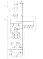
図1は、この発明に係るファントム電源装置と共に用いることによって、LEDによる発光体の表示機能を十分に生かすことができるコンデンサマイクロホンの好ましい例を示している。先ずは、この発明に係るファントム電源装置の説明の前に、図1に示すコンデンサマイクロホンについて説明する。
なお図1に示すコンデンサマイクロホン1については、すでに説明した図4に示したコンデンサマイクロホンの各部と同一の機能を果たす部分を同一の符号で示している。したがって、その詳細な説明は省略する。
FIG. 1 shows a preferred example of a condenser microphone capable of fully utilizing the display function of a light emitting body by an LED when used together with the phantom power supply device according to the present invention. First, before describing the phantom power supply device according to the present invention, the condenser microphone shown in FIG. 1 will be described.
In the condenser microphone 1 shown in FIG. 1, parts that perform the same functions as those of the already-described condenser microphone shown in FIG. 4 are denoted by the same reference numerals. Therefore, detailed description thereof will be omitted.
図1に示すコンデンサマイクロホン1においては、発光体として4つのLED(D1〜D4)を直列接続したものが具備されている。この4つの直列接続されたLEDには、信号の平衡伝送路である3ピンタイプの出力コネクタ3より、定電流ダイオードCR2,CR3を介して発光駆動電流が供給されるように構成されている。
すなわち、出力コネクタ3の2番ピンP2には定電流ダイオードCR2のアノードが接続され、3番ピンP3には定電流ダイオードCR3のアノードがそれぞれ接続されている。そして、定電流ダイオードCR2とCR3の各カソードは共通接続され、共通接続された定電流ダイオードのカソードが、直列接続された筆頭のLED(D1)のアノードに接続されている。
The condenser microphone 1 shown in FIG. 1 is provided with four LEDs (D1 to D4) connected in series as a light emitting body. A light emitting drive current is supplied to the four LEDs connected in series from a 3-pin
That is, the anode of the constant current diode CR2 is connected to the second pin P2 of the
一方、直列接続された末尾のLED(D4)のカソードは、出力コネクタ3の1番ピンP1に接続されており、コンデンサマイクロホン1の出力コネクタ3と、マイクアンプユニット11側のコネクタ12を結ぶシールドケーブルを介して、マイクアンプユニット11に配置された遠隔操作用のスイッチSWに接続されている。
そして、遠隔操作用のスイッチSWがオン操作されることで、直列接続されたLED(D1〜D4)は点灯し、スイッチSWがオフ操作されることで消灯する。このLEDの点灯および消灯動作については、図2および図3に基づいて後で説明する。
On the other hand, the cathode of the last LED (D4) connected in series is connected to the first pin P1 of the
Then, when the switch SW for remote operation is turned on, the LEDs (D1 to D4) connected in series are turned on, and when the switch SW is turned off, the LEDs are turned off. The operation of turning on and off the LED will be described later based on FIGS. 2 and 3.
図1に示したコンデンサマイクロホン1の構成によると、平衡伝送路に接続された定電流ダイオードCR2,CR3を介して、直列接続されたLED(D1〜D4)に対して発光駆動電流を供給するように作用する。またコンデンサマイクロホン1のインピーダンス変換回路と2つのオペアンプOP1,OP2を含む音声信号処理回路は、ツェナーダイオードZDとコンデンサC5を含む定電圧回路4から動作電源を得ている。 According to the configuration of the condenser microphone 1 shown in FIG. 1, the emission drive current is supplied to the LEDs (D1 to D4) connected in series via the constant current diodes CR2 and CR3 connected to the balanced transmission path. Act on. The audio signal processing circuit including the impedance conversion circuit of the condenser microphone 1 and the two operational amplifiers OP1 and OP2 obtains operating power from the constant voltage circuit 4 including the Zener diode ZD and the capacitor C5.
したがって、この構成によるとLED(D1〜D4)の点灯および消灯により、定電圧回路4に電圧変動を及ぼすのを避けることができる。これにより定電圧回路4によって動作する前記した音声信号処理回路に、LED(D1〜D4)の点滅に伴う雑音が重畳するのを避けることができる。 Therefore, according to this configuration, it is possible to prevent the constant voltage circuit 4 from changing in voltage due to turning on and off of the LEDs (D1 to D4). As a result, it is possible to avoid the noise that accompanies the blinking of the LEDs (D1 to D4) being superimposed on the audio signal processing circuit that is operated by the constant voltage circuit 4.
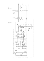
図2はマイクアンプユニット11側に搭載されたこの発明に係るファントム電源装置の第1の例を示した回路構成図である。
マイクアンプユニット11側に備えたコネクタ12のホット側2番ピンP2と、コールド側3番ピンP3には、直流カットコンデンサC11,C12が接続され、コンデンサマイクロホン1から平衡伝送される音声信号は、差動増幅回路として機能するオペアンプOP11の非反転入力端子と、反転入力端子に供給される。これによりオペアンプOP11の出力端子Outには、音声信号の平衡出力がもたらされ、この出力は図示せぬマイクアンプによって増幅される。
FIG. 2 is a circuit configuration diagram showing a first example of the phantom power supply device according to the present invention mounted on the
DC cut capacitors C11 and C12 are connected to the hot side second pin P2 and the cold side third pin P3 of the
一方、マイクアンプユニット11における前記オペアンプOP11を除いたファントム電源装置には、第1直流電源E11が備えられ、この実施の形態においては第1直流電源E11の出力電圧は規格において最も低い12Vに設定される。この12Vの直流電源は一般に商用電源から生成されるが、設備の都合により前記したように外付けのバッテリーを用いる場合もある。
On the other hand, the phantom power supply device excluding the operational amplifier OP11 in the
そして、第1直流電源E11の正極端子には、ホット側供給抵抗(680Ω)R11とコールド側供給抵抗(680Ω)R12の各一端部がそれぞれ接続され、抵抗R11の他端部はコネクタ12の2番ピンP2に接続され、また抵抗R12の他端部はコネクタ12の3番ピンP3に接続されている。そして、第1直流電源E11の負極端子は、グランドラインに接続されている。
Then, one end of each of the hot-side supply resistance (680Ω) R11 and the cold-side supply resistance (680Ω) R12 is connected to the positive electrode terminal of the first DC power supply E11, and the other end of the resistance R11 is connected to the
したがって、第1直流電源E11からの供給電流は、図1に示すコネクタ3と12を結ぶ前記したホット側信号線とコールド側信号線を経由して、前記コンデンサマイクロホン1に供給される。
そして、図1に示したコンデンサマイクロホン1の定電圧回路4に供給され、コンデンサマイクロホン1におけるインピーダンス変換素子としてのFET(Q1)および第1と第2のオペアンプOP1,OP2に対して駆動電圧が供給される。
Therefore, the current supplied from the first DC power source E11 is supplied to the condenser microphone 1 via the hot side signal line and the cold side signal line connecting the
Then, it is supplied to the constant voltage circuit 4 of the condenser microphone 1 shown in FIG. 1, and the drive voltage is supplied to the FET (Q1) as the impedance conversion element and the first and second operational amplifiers OP1 and OP2 in the condenser microphone 1. To be done.
また、図2に示すファントム電源装置には、第2直流電源E12も具備されている。
この実施の形態における第2直流電源E12は、第1直流電源E11からの出力電圧を利用する電圧コンバータIC(IC1)により構成されており、この電圧コンバータICは、一例としてリニアテクノロジー社(LINEAR TECHNOLOGY 米国)の反転型チャージポンプ“LTC3261”を利用することができる。
The phantom power supply device shown in FIG. 2 also includes a second DC power supply E12.
The second DC power supply E12 in this embodiment is composed of a voltage converter IC (IC1) that uses the output voltage from the first DC power supply E11, and this voltage converter IC is, for example, Linear Technology Corporation (LINEAR TECHNOLOGY). A reverse charge pump "LTC3261" (U.S.A.) can be used.
この電圧コンバータICによると、ICのグランドラインを基準として、入力正電圧(+Vin)に応じて負電圧(−Vout)が出力され、その標準的な応用例としては、第1直流電源E11からの入力正電圧+12Vに基づいて、同電位の負電圧−12Vを得ることができる。
また、電圧コンバータIC(IC1)の入出力端子のコンデンサC13,C14と、チャージポンプ用コンデンサC15の特性を選定することで、入力正電圧(+Vin)に対して適宜ステップダウンした負電圧(−Vout)を得ることも可能である。
なお、前記した機能を果たす電圧コンバータICは、現状において多種類のものが提供されており、これは適宜選択することができる。
According to this voltage converter IC, a negative voltage (-Vout) is output according to the input positive voltage (+Vin) with the ground line of the IC as a reference, and as a standard application example thereof, the first DC power source E11 Based on the input positive voltage +12V, the negative voltage -12V of the same potential can be obtained.
Further, by selecting the characteristics of the capacitors C13 and C14 of the input/output terminals of the voltage converter IC (IC1) and the charge pump capacitor C15, a negative voltage (-Vout) appropriately stepped down from the input positive voltage (+Vin) is selected. ) Is also possible.
It should be noted that various types of voltage converter ICs that fulfill the above-mentioned functions are currently provided and can be appropriately selected.
図2に示すファントム電源装置の回路構成によると、前記第1直流電源E11の負極端子(グランドライン)は電圧コンバータICのグランド(GND)に接続され、第1直流電源E11の正極端子は電圧コンバータICの入力正電圧(+Vin)が印加される入力端子に接続され、電圧コンバータICの負電圧(−Vout)を出力する出力端子に前記した遠隔操作スイッチSWが直列接続される。
つまり、前記第1直流電源E11の負極端子(グランドライン)に、電圧コンバータICによる第2直流電源E12の正極端子が順方向に直列接続され、第2直流電源E12の負極端子に、前記した遠隔操作スイッチSWが直列に接続されたものとなる。
したがって、この遠隔操作スイッチSWをオン操作することで、コンデンサマイクロホン1に搭載された直列接続されたLED(D1〜D4)に対して、ファントム電源装置における前記第1直流電源E11と、第2直流電源E12の加算電圧が供給されることになる。
According to the circuit configuration of the phantom power supply device shown in FIG. 2, the negative terminal (ground line) of the first DC power supply E11 is connected to the ground (GND) of the voltage converter IC, and the positive terminal of the first DC power supply E11 is the voltage converter. The remote control switch SW is connected in series to the output terminal of the voltage converter IC that outputs the negative voltage (-Vout), which is connected to the input terminal to which the input positive voltage (+Vin) of the IC is applied.
That is, the positive terminal of the second DC power supply E12 by the voltage converter IC is connected in series in the forward direction to the negative terminal (ground line) of the first DC power supply E11, and the remote terminal is connected to the negative terminal of the second DC power supply E12. The operation switches SW are connected in series.
Therefore, by turning on the remote control switch SW, the LEDs (D1 to D4) mounted in series on the condenser microphone 1 are connected to the first DC power supply E11 and the second DC power supply in the phantom power supply device. The added voltage of the power source E12 is supplied.
したがって、ファントム電源装置の規格において定められた例えば最も低い供給電圧である12Vを選択した場合であっても、コンデンサマイクロホン1に搭載された直列接続されたLED(D1〜D4)に対して余裕のある駆動電圧を与えることができ、これによりLEDを十分な発光輝度で明瞭に点灯させることが可能となる。 Therefore, even when 12V, which is the lowest supply voltage defined in the standard of the phantom power supply device, is selected, there is a margin for the serially connected LEDs (D1 to D4) mounted on the condenser microphone 1. A certain drive voltage can be applied, which allows the LED to be illuminated clearly with sufficient emission brightness.
図3は、この発明に係るファントム電源装置の第2の例を示したものである。なお図3においては、すでに説明した図2に示した各部と同一の機能を果たす部分を同一の符号で示しており、その説明は省略する。 FIG. 3 shows a second example of the phantom power supply device according to the present invention. Note that, in FIG. 3, parts that perform the same functions as the parts shown in FIG.
この図3に示す例における第2直流電源E12は、商用電源から生成される場合と、設備の都合により外付けのバッテリーを用いる場合もある。
そして、第2直流電源E12の正極端子は、グランドラインに接続されることで、第1直流電源E11の負極端子に順方向に直列接続され、第2直流電源E12の負極端子に、遠隔操作スイッチSWが直列に接続される。
The second DC power source E12 in the example shown in FIG. 3 may be generated from a commercial power source or may be an external battery for convenience of equipment.
The positive electrode terminal of the second DC power source E12 is connected in series to the negative electrode terminal of the first DC power source E11 by being connected to the ground line, and the remote control switch is connected to the negative electrode terminal of the second DC power source E12. SW is connected in series.
したがって、この遠隔操作スイッチSWをオン操作することで、図1に示したコンデンサマイクロホン1に搭載された直列接続されたLED(D1〜D4)に対して、ファントム電源装置における前記第1直流電源E11と、第2直流電源E12の加算電圧が供給されることになり、この基本構成は図2に示した例と同様である。
それ故、図3に示すファントム電源装置においても、図2に示した例と同様の作用効果を得ることができる。
Therefore, when the remote control switch SW is turned on, the first DC power source E11 in the phantom power source device for the LEDs (D1 to D4) connected in series mounted on the condenser microphone 1 shown in FIG. Then, the added voltage of the second DC power source E12 is supplied, and the basic configuration is the same as the example shown in FIG.
Therefore, also in the phantom power supply device shown in FIG. 3, it is possible to obtain the same effect as that of the example shown in FIG.
以上説明したファントム電源装置と共に使用されるコンデンサマイクロホン1においては、マイクアンプユニット11に配置された遠隔操作スイッチSWにより、コンデンサマイクロホン1に搭載された発光体としてのLED(D1〜D4)に通電させるようにしている。しかし、この発明に係るファントム電源装置は、発光体としてのLEDへの電流供給のみならず、コンデンサマイクロホンに搭載されたLED以外の電流駆動素子に対しても、遠隔操作スイッチSWにより動作電流を供給することができ、同様の作用効果を得ることができる。なお、接続されるLEDの個数は任意であり、複数のLEDを直並列接続してもよい。また、発光素子としてLEDに限らず、OLED(有機発光ダイオード)などの他の発光素子を用いてもよい。
In the condenser microphone 1 used together with the phantom power supply device described above, the LEDs (D1 to D4) as light emitters mounted on the condenser microphone 1 are energized by the remote control switch SW arranged in the
1 コンデンサマイクロホン
2 マイクロホンユニット
3 出力コネクタ
4 定電圧回路
11 マイクアンプユニット(ファントム電源装置)
12 マイクアンプユニット側コネクタ
C1〜C5 コンデンサ
C11〜C15 コンデンサ
CR1〜CR3 定電流ダイオード
D1〜D4 LED(発光体)
E11 第1直流電源
E12 第2直流電源
IC1 電圧コンバータIC
OP1,OP2 オペアンプ
OP11 オペアンプ
Out 音声信号出力端子
P1,P2,P3 端子ピン
Q1 FET(インピーダンス変換器)
Q2,Q3 トランジスタ
R1〜R5 抵抗
R11 ホット側供給抵抗
R12 コールド側供給抵抗
SI フレームグランド端子
SW 遠隔操作スイッチ
1 condenser microphone 2
12 Microphone amplifier unit side connector C1 to C5 capacitors C11 to C15 capacitors CR1 to CR3 constant current diodes D1 to D4 LEDs (light emitters)
E11 First DC power supply E12 Second DC power supply IC1 Voltage converter IC
OP1, OP2 operational amplifier OP11 operational amplifier Out Audio signal output terminal P1, P2, P3 terminal pin Q1 FET (impedance converter)
Q2, Q3 Transistors R1 to R5 Resistance R11 Hot side supply resistance R12 Cold side supply resistance SI Frame ground terminal SW Remote control switch
Claims (3)
ホット側供給抵抗とコールド側供給抵抗をそれぞれ介して前記ホット側信号線とコールド側信号線を経由して、前記コンデンサマイクロホンに給電電流を供給する第1直流電源と、
第2直流電源と、
一端が前記第2直流電源の一方の端子に接続され、コンデンサマイクロホンに搭載された電流駆動素子への通電を制御する遠隔操作スイッチが備えられ、
前記遠隔操作スイッチのオン操作により、コンデンサマイクロホンに搭載された前記電流駆動素子に対して、第1直流電源と第2直流電源の加算電圧が供給されることを特徴とするファントム電源装置。 A phantom power supply device for supplying power to a condenser microphone in which an audio signal is balanced-output by a hot signal line and a cold signal line ,
Through the hot-side signal line and the cold-side signal line host Tsu-up side feed resistors and the cold-side feed resistors and via respectively a first DC power supply for supplying a power supply current to the condenser microphone,
A second DC power supply,
One end connected to one terminal of the second DC power supply, remote control switch Bei Erare to control the energization of the onboard current-driven elements in the condenser microphone,
The ON operation of the prior SL remote control switch, to the current-driven elements mounted in the condenser microphone, phantom power supply first DC power supply and the added voltage of the second DC power source, characterized in that it is supplied.
Priority Applications (2)
| Application Number | Priority Date | Filing Date | Title |
|---|---|---|---|
| JP2016130598A JP6698994B2 (en) | 2016-06-30 | 2016-06-30 | Phantom power supply |
| US15/497,880 US10003875B2 (en) | 2016-06-30 | 2017-04-26 | Phantom power supply device |
Applications Claiming Priority (1)
| Application Number | Priority Date | Filing Date | Title |
|---|---|---|---|
| JP2016130598A JP6698994B2 (en) | 2016-06-30 | 2016-06-30 | Phantom power supply |
Publications (3)
| Publication Number | Publication Date |
|---|---|
| JP2018006980A JP2018006980A (en) | 2018-01-11 |
| JP2018006980A5 JP2018006980A5 (en) | 2019-07-25 |
| JP6698994B2 true JP6698994B2 (en) | 2020-05-27 |
Family
ID=60808119
Family Applications (1)
| Application Number | Title | Priority Date | Filing Date |
|---|---|---|---|
| JP2016130598A Expired - Fee Related JP6698994B2 (en) | 2016-06-30 | 2016-06-30 | Phantom power supply |
Country Status (2)
| Country | Link |
|---|---|
| US (1) | US10003875B2 (en) |
| JP (1) | JP6698994B2 (en) |
Families Citing this family (2)
| Publication number | Priority date | Publication date | Assignee | Title |
|---|---|---|---|---|
| JP6826724B2 (en) * | 2017-01-05 | 2021-02-10 | 株式会社オーディオテクニカ | Microphone |
| USD869430S1 (en) * | 2018-01-29 | 2019-12-10 | Amazon Technologies, Inc. | Headphones |
Family Cites Families (4)
| Publication number | Priority date | Publication date | Assignee | Title |
|---|---|---|---|---|
| JP4528465B2 (en) | 2001-06-08 | 2010-08-18 | 株式会社オーディオテクニカ | Microphone |
| US7620189B2 (en) * | 2004-03-30 | 2009-11-17 | Akg Acoustics Gmbh | Polarization voltage setting of microphones |
| JP5545859B2 (en) * | 2010-09-29 | 2014-07-09 | 株式会社オーディオテクニカ | Phantom power circuit |
| JP5967823B2 (en) * | 2012-10-24 | 2016-08-10 | 株式会社オーディオテクニカ | Variable directivity condenser microphone |
-
2016
- 2016-06-30 JP JP2016130598A patent/JP6698994B2/en not_active Expired - Fee Related
-
2017
- 2017-04-26 US US15/497,880 patent/US10003875B2/en not_active Expired - Fee Related
Also Published As
| Publication number | Publication date |
|---|---|
| JP2018006980A (en) | 2018-01-11 |
| US20180007459A1 (en) | 2018-01-04 |
| US10003875B2 (en) | 2018-06-19 |
Similar Documents
| Publication | Publication Date | Title |
|---|---|---|
| JP6440164B2 (en) | Microphone connection device | |
| EP1811657A3 (en) | Nested transimpedance amplifier | |
| US7046815B2 (en) | Microphone | |
| JP6698994B2 (en) | Phantom power supply | |
| TWI434602B (en) | Current mirror circuit | |
| JP6826724B2 (en) | Microphone | |
| US8437484B2 (en) | Switching circuit and electronic device using the same | |
| CN108112129B (en) | LED constant current driving circuit | |
| CN111556604A (en) | Lamp area display circuit, lamp area display device and robot | |
| US9706618B2 (en) | Audio output circuit of condenser microphone | |
| KR20090065848A (en) | Apparatus for driving lighting system using light emitting diode | |
| US9538273B2 (en) | Microphone device including light emitting elements | |
| TW201616921A (en) | Light emitting device driving circuit and method thereof | |
| JP2011258797A (en) | Drive control circuit of light-emitting diode and backlight system | |
| US8948421B2 (en) | Ribbon microphone circuit | |
| JP6533452B2 (en) | Microphone power circuit | |
| CN210007956U (en) | music light circuit and music light device | |
| TWI662859B (en) | Feedback circuit capable of regulating response according to variation of dimming signal | |
| JP7139765B2 (en) | lighting equipment | |
| NL2014677A (en) | Phantom power supply for microphone. | |
| WO2020147057A1 (en) | Lamp and circuit unit thereof, and lamp power supply method | |
| JP2011028953A (en) | Power supply device | |
| JPH08899U (en) | Power supply device for video camera and video light | |
| KR20020059528A (en) | Microphone circuit | |
| JP2019160538A (en) | LED drive circuit |
Legal Events
| Date | Code | Title | Description |
|---|---|---|---|
| A521 | Request for written amendment filed |
Free format text: JAPANESE INTERMEDIATE CODE: A523 Effective date: 20190621 |
|
| A621 | Written request for application examination |
Free format text: JAPANESE INTERMEDIATE CODE: A621 Effective date: 20190621 |
|
| RD04 | Notification of resignation of power of attorney |
Free format text: JAPANESE INTERMEDIATE CODE: A7424 Effective date: 20190808 |
|
| RD02 | Notification of acceptance of power of attorney |
Free format text: JAPANESE INTERMEDIATE CODE: A7422 Effective date: 20190828 |
|
| A977 | Report on retrieval |
Free format text: JAPANESE INTERMEDIATE CODE: A971007 Effective date: 20200312 |
|
| TRDD | Decision of grant or rejection written | ||
| A01 | Written decision to grant a patent or to grant a registration (utility model) |
Free format text: JAPANESE INTERMEDIATE CODE: A01 Effective date: 20200317 |
|
| A61 | First payment of annual fees (during grant procedure) |
Free format text: JAPANESE INTERMEDIATE CODE: A61 Effective date: 20200317 |
|
| R150 | Certificate of patent or registration of utility model |
Ref document number: 6698994 Country of ref document: JP Free format text: JAPANESE INTERMEDIATE CODE: R150 |
|
| LAPS | Cancellation because of no payment of annual fees |