JP6697865B2 - Taper hole drilling tool - Google Patents
Taper hole drilling tool Download PDFInfo
- Publication number
- JP6697865B2 JP6697865B2 JP2015204602A JP2015204602A JP6697865B2 JP 6697865 B2 JP6697865 B2 JP 6697865B2 JP 2015204602 A JP2015204602 A JP 2015204602A JP 2015204602 A JP2015204602 A JP 2015204602A JP 6697865 B2 JP6697865 B2 JP 6697865B2
- Authority
- JP
- Japan
- Prior art keywords
- tip
- main shaft
- gear
- shaft
- male screw
- Prior art date
- Legal status (The legal status is an assumption and is not a legal conclusion. Google has not performed a legal analysis and makes no representation as to the accuracy of the status listed.)
- Active
Links
Images


Description
この発明は、刃先の消耗が早くなる問題をなくするテーパー穴加工ツールに関する。 The present invention relates to a tapered hole machining tool that eliminates the problem of rapid wear of the cutting edge.
ワークに前もって加工してある穴にテーパー穴を加工する従来の技術としては、下穴にカッターのボデーを貫通したのち、このカッターを後退移動と横移動(カッターのボデーの径方向)との複合移動をさせながら、下穴にテーパー穴を加工している(特許文献1)。 The conventional technique for forming a tapered hole in a hole that has been machined in advance is to combine the backward movement and the lateral movement (radial direction of the cutter body) of this cutter after penetrating the body of the cutter into the prepared hole. A taper hole is formed in the pilot hole while moving (Patent Document 1).
ところで、特許文献1の加工方式によると、ストレートシャンクの先端にストレートシャンクの軸心から所定量オフセットした位置に小径な首部を介して逆円錐台形のボデーを一体に形成すると共に、このボデーには、加工すべきテーパー穴の形状に応じたいわゆる先広がり形状の直線刀の如き単一の切刃が形成された加工テーパー穴の形状に見合う専用のカッターが必要になる。
By the way, according to the processing method of
このため、テーパー穴の周穴斜面形状に合致する切刃を有するカッターを加工テーパー穴の斜面が変わるその都度必要になる。すなわち、市販の刃物(チップ)を使用することができない問題があった。 Therefore, a cutter having a cutting edge that matches the peripheral hole slope shape of the taper hole is required each time the slope surface of the taper hole is changed. That is, there is a problem that a commercially available blade (chip) cannot be used.
その要因は、テーパー穴の全面幅を成形切刃でツールの主軸の下り送りによって一発で行っていることに起因する。 The cause is that the entire width of the tapered hole is made by one shot by the downward feed of the tool spindle with the forming cutting edge.
特に、近年、加工製品の寿命を考慮して焼き入れ硬度の高い材質が一般的に使用されるようになってきているので、加工切刃(カッター)の寿命が問題、すなわち、切刃の面幅全体の加工負荷が大きく、またテーパー穴の大径部と小径部の切削スピードが違うために理想的な切削スピードで加工できず、刃先の消耗が早くなる問題があった。 In particular, in recent years, materials with high quenching hardness have been generally used in consideration of the life of processed products, so the life of the processing cutting edge (cutter) is a problem, that is, the surface of the cutting edge. Since the machining load on the entire width is large and the cutting speeds of the large diameter part and the small diameter part of the tapered hole are different, it is impossible to machine at the ideal cutting speed, and there is a problem that the wear of the cutting edge becomes faster.
そこで、この発明は、上述の問題を解決したテーパー穴加工ツールを提供することにある。 Then, this invention is providing the taper hole drilling tool which solved the above-mentioned problem.
上記の課題を解決するために、この発明は、工作機械に対し位置決め手段を介し不回転状態に接続するケーシングと、このケーシングの中心に貫通してフリーに回転するように軸承すると共に、上記工作機械側から回転伝達を受けるように設けた主軸と、この主軸に平行して上記ケーシング内でフリーに回転するように軸承した伝達軸と、上記主軸から上記伝達軸に回転伝達を受けるように設けた噛み合う歯車と、上記主軸内の中心線上に定位置でフリーに回転するように軸承した送り雄ネジと、上記主軸の先端側内にガイド手段により上記主軸の軸線方向にスライドし、かつピンにより上記送り雄ネジが回転しても上記主軸に対して回り止めされるよう組み込んだスライドロッドと、このスライドロッドの末端面から内方に向け上記送り雄ネジをねじ込むように設けた雌ネジと、上記主軸の先端に設けたガイドにより仕上げテーパー穴の角度に沿ってガイド手段によりガイドされてスライドする刃物ホルダと、この刃物ホルダの低所先端にセットした刃物と、上記スライドロッドの周面先端部から先端に向け先細りになるように設けた勾配面部と、上記主軸の先端内に支軸を介し中間を回動自在に支持すると共に、上記勾配面部に先端を当接し、かつ上記刃物ホルダに末端を係合したレバーと、このレバーに上記勾配面部に上記レバーの先端が常に圧接するように付与した押圧手段と、上記伝達軸の回転を上記送り雄ネジに伝達するように設けた減速伝達手段とからなる構成を採用する。 In order to solve the above-mentioned problems, the present invention provides a casing that is connected to a machine tool in a non-rotating state via a positioning means, a bearing that pierces the center of the casing so as to rotate freely, and the above-mentioned machining tool. A main shaft provided to receive rotation transmission from the machine side, a transmission shaft parallel to the main shaft so as to freely rotate in the casing, and a main shaft provided to receive rotation transmission from the main shaft to the transmission shaft. Gears that mesh with each other, a feed male screw that is rotatably supported at a fixed position on the center line of the main shaft, a guide means that slides in the axial direction of the main shaft, and a pin A slide rod incorporated so as to be prevented from rotating with respect to the main shaft even if the feed male screw rotates, and a female screw provided so as to screw the feed male screw inward from the end face of the slide rod, A blade holder that slides by being guided by guide means along the angle of the finishing taper hole by a guide provided at the tip of the main shaft, a blade set at the low end of the blade holder, and the tip of the peripheral surface of the slide rod. A sloping surface portion provided so as to taper from the end to the tip, and a middle portion is rotatably supported in the tip of the main shaft via a support shaft, and the tip abuts on the sloping surface portion and ends at the blade holder. A lever engaged with the lever, a pressing means provided to the lever so that the tip of the lever is always in pressure contact with the inclined surface portion, and a deceleration transmission means provided to transmit the rotation of the transmission shaft to the feed male screw. The configuration consisting of and is adopted.
また、前記減速伝達手段が、送り雄ネジの外周でフリーに回転するように組み込んだ外、内歯車と、この外、内歯車の外歯に回転を伝達するように噛合させて伝達軸に設けた第1歯車と、送り雄ネジの外周に設けた第2歯車と、主軸内の複数位置に軸承して上記外、内歯車の内歯及び外歯に噛合して上記第2歯車に回転を伝達するように設けた遊星歯車とで構成した構成を採用することもある。 The deceleration transmitting means is provided on the transmission shaft so as to mesh with the external and internal gears incorporated so as to rotate freely around the outer circumference of the feed male screw and the external teeth of the external and internal gears so as to transmit the rotation. The first gear, the second gear provided on the outer circumference of the feed male screw, and the plurality of positions in the main shaft are supported to mesh with the inner and outer teeth of the outer and inner gears to rotate the second gear. A configuration configured with a planetary gear provided so as to transmit may be adopted.
以上のように、この発明のテーパー穴加工ツールによれば、主軸の一方向回転(正転)にともない歯車から伝達軸の回転を、減速伝達手段から送り雄ネジに伝達し、この回転伝達によりスライドロッドを前進させる。 As described above, according to the tapered hole machining tool of the present invention, the rotation of the transmission shaft from the gear is transmitted from the gear to the feed male screw by the rotation of the main shaft in one direction (normal rotation). Move the slide rod forward.
すると、前進するスライドロッドの勾配面部によりレバーを回動させながら、押圧手段の押圧力にさからって刃物ホルダをガイドにより案内しながら押し出すので、刃物ホルダの保持刃物により下穴のテーパー穴加工を行うことができる。 Then, while the lever is rotated by the sloped surface of the slide rod that moves forward, the tool holder pushes out while guiding the tool holder according to the pressing force of the pressing means. It can be performed.
このため、切削切刃を特殊な形状に加工することなく、市販の刃物(チップ)で加工することができる特有な効果がある。 Therefore, there is a peculiar effect that it is possible to process with a commercially available blade (tip) without processing the cutting edge into a special shape.
また、加工時に刃物、ワーク材質条件に最適な主軸回転(切削時周速)を設定し加工を行うが、その回転を減速伝達手段を用いて、刃物支持ホルダのスライド部に取り出し、定速で(切り込み速度が変化することなく)最適な切り込み量をあたえることができる効果がある。 When machining, the spindle rotation (peripheral speed during cutting) that is optimal for the blade and workpiece material conditions is set for machining, but this rotation is taken out to the slide part of the blade support holder using deceleration transmission means and is maintained at a constant speed. There is an effect that an optimum cutting amount can be given (without changing the cutting speed).
さらに、主軸の回転を取り出して送り雄ネジを回動させる減速伝達手段に外、内歯車を使用しているので、二段の歯車で取り出すことができ、コンパクトになる効果がある。 Further, since the external and internal gears are used as the deceleration transmission means for taking out the rotation of the main shaft and rotating the feeding male screw, it is possible to take out with the two-stage gears, which has the effect of being compact.
次に、この発明の実施形態を添付図面に基づいて説明する。
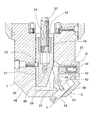
実施形態の図1から図3に示す1は、工作機械Aに対し位置決め手段Bを介し不回転状態に接続するケーシングで、このケーシング1には、ベアリング2によりフリーに回転するように軸承した主軸3が貫通させてある。
Next, an embodiment of the present invention will be described with reference to the accompanying drawings.
1 to 3 of the embodiment is a casing which is connected to a machine tool A in a non-rotating state via a positioning means B, and a main shaft which is rotatably supported by a
上記の位置決め手段Bは、例えば、図1に示すように、ケーシング1の外側から突出する突出部材4に上面が開放する凹入孔5を設けて、この凹入孔5に上方への突出力を付与するバネ6を挟み込んだ軸材7を嵌入し、工作機械Aに主軸3をセットした際、工作機械Aのブロック8のテーパー穴9にバネ6を圧縮しながら軸材7の先端が嵌入して係合関係になるので、ケーシング1が不回転状態になるようにしてある。
In the positioning means B, for example, as shown in FIG. 1, a protruding
なお、ケーシング1の外周から突出して軸材7の貫通孔13を有する片10を設けて、この片10に設けてある孔11に突出部材4から上方に起立するピン12を貫通させて、主軸3に対するケーシング1の回り止めと、軸材7の昇降をガイドするようにしてある。
In addition, a
また、工作機械Aにケーシング1を接続した際に、工作機械Aのスピンドルaから主軸3に回転を伝達するようになっている。
Further, when the
この回転伝達は、例えば、図1に示すように、スピンドルaのテーパー穴14に主軸3の元部のテーパーシャンク15を嵌入するようになっている。
For this rotation transmission, for example, as shown in FIG. 1, the
さらに、ケーシング1内には、主軸3に平行してフリーに回転する伝達軸16が軸承してあり、この伝達軸16に設けてある第1歯車17には、主軸3の外周に主軸3と共に回転する第2歯車18が設けてある。
Further, a
また、主軸3内の中心線上には、ベアリング19を介し定位置でフリーに回転するように軸承した送り雄ネジ20が設けてあり、主軸3の先端側内には、ガイド手段としての外周面軸線方向の縦溝21と、この縦溝21に先端が嵌入するように主軸3の外周面からねじ込んだピン22により主軸3に対して回り止めされ、かつ図示昇降方向にスライドするスライドロッド23が組み込まれ、このスライドロッド23の上端面から下方に向けて雌ネジ24を設けて、この雌ネジ24に送り雄ネジ20がねじ込んである。
Further, on the center line of the
さらに、主軸3の主軸先端48(図示下端)には、被加工ワークWに前もって設けてあるバルブシートなどのテーパー穴X(図5参照)の角度に沿ってガイド手段Cによりガイドされてスライドする刃物ホルダ25が設けてある。
Further, the main shaft tip 48 (lower end in the figure) of the
上記ガイド手段Cは、図1、2に示すように、主軸3の先端(下端)面に先端面(下位端面)が開放するレールの役目をするカバー26がボルトなどの固着手段を介し取り付けてあり、このカバー26の先端面開口から内方に刃物ホルダ25を挿入することで、刃物ホルダ25が斜め上下にスライドできるようになっている。
なお、テーパー穴Xの角度が変わると、その角度に見合う主軸先端48を使用する。
As shown in FIGS. 1 and 2, the guide means C has a
When the angle of the tapered hole X changes, the
上記刃物ホルダ25の先端(図示下端)には、切削刃物Yが支持(この支持は、ビス止めなど既知につき説明を省略する)されている。 The cutting tool Y is supported at the tip (lower end in the drawing) of the tool holder 25 (this support is known as screw fixing and the description thereof is omitted).
また、スライドロッド23の周面先端部から先端に向け先細りになる勾配面部27が設けてある。
Further, there is provided a
さらに、主軸3の先端内に中空室28を設けて、この中空室28内にレバー29の中間を支軸30を介し回動自在に支承すると共に、このレバー29の先端は、勾配面部27に当接し、レバー29の末端は、刃物ホルダ25の途中に係合させる。
Further, a
上記の係合は、図示の場合、刃物ホルダ25に凹入部31を設けて、この凹入部31にレバー29の末端を嵌入して係合関係にしてある。
In the illustrated case, the above engagement is provided by providing a
さらに、勾配面部27に対しレバー29の先端が常に圧接するように押圧手段Dが設けてある。
Further, the pressing means D is provided so that the tip of the
上記の押圧手段Dとしては、図示の場合、筒状部32にスライダ33を嵌入して、筒状部32に一端が筒状部32の底に、他端がスライダ33の末端にそれぞれ当接するバネ34を組み込んで構成してある。
As the pressing means D, in the illustrated case, the
すると、スライダ33の先端がレバー29の先端部に押し付けられて、勾配面部27に対しレバー29の先端を安定した状態で常に圧接することができる。
Then, the tip of the
また、伝達軸16の回転を歯車の組み合わせにより構成した減速伝達手段Eを介し送り雄ネジ20に伝達するようにしてある。
Further, the rotation of the
図中36はスライドロッド23がどの位置にいるかを目視で確認できるようにしたピンで、長孔35のどの位置にいるかを確認できる。
上記のように構成すると、主軸3の一方向回転(正転)にともない第2歯車18から第1歯車17により伝達軸16がドライブされ、次に減速伝達手段Eにより減速されて送りネジ20をドライブする。
With the above configuration, the
すると、送り雄ネジ20のねじ込み雌ネジ24を有するスライドロッド23が降送されて、この降送にともない勾配面部27によりレバー29を図1、2の時計方向に回動(揺動)する。
Then, the
すると、レバー29の先端移動によって、刃物ホルダ25を図4に示すように押し出すので、図5に示すように、ワークWのテーパー穴Xを刃物Yにより切削する。
Then, since the
なお、切削終了後には、主軸3の他方向回転(逆転)にともない上述の逆動作によってスライドロッド23を上昇させ、またレバー29の反時計方向の回動(揺動)にともない刃物ホルダ25を押し戻す(図1に示すように)。
図中38はスライドロッド23の嵌入孔である。
After the cutting is completed, the
次に、前記の減速伝達手段Eの構成を図1、2により説明する。
送り雄ネジ20の外周に組み込んだフリーに回転する外、内歯車41と、この外、内歯車41の外歯42に回転を伝達するように伝達軸16に設けた噛合第1歯車43と、送り雄ネジ20の外周に設けた第2歯車44と、主軸3内の複数位置に支軸45を介して軸承すると共に、外、内歯車41の内歯46と外歯42とに噛合する遊星歯車47とで減速伝達手段Eを構成する。
なお、内歯46の歯数は、外歯42の歯数より少なくなっている。
Next, the structure of the deceleration transmission means E will be described with reference to FIGS.
A freely rotating outer/
The number of teeth of the
すると、主軸3の回転を取り出して送り雄ネジ20を回動させる減速に、外、内歯車41を使用しているので、二段の歯車で取り出すことができ、著しくコンパクトになる効果がある。
Then, since the external and
A 工作機械
a スピンドル
B 位置決め手段
C ガイド手段
D 押圧手段
E 減速伝達手段
W ワーク
X テーパー穴
Y 刃物
1 ケーシング
2 ベアリング
3 主軸
4 突出部材
5 凹入孔
6 バネ
7 軸材
8 ブロック
9 テーパー穴
10 片
11 孔
12 ピン
13 貫通孔
14 テーパー穴
15 テーパーシャンク
16 伝達軸
17 第1歯車
18 第2歯車
19 ベアリング
20 送り雄ネジ
21 縦溝
22 ピン
23 スライドロッド
24 雌ネジ
25 刃物ホルダ
26 カバー
27 勾配面部
28 中空室
29 レバー
30 支軸
31 凹入部
32 筒状部
33 スライダ
34 バネ
41 外、内歯車
42 外歯
43 第1歯車
44 第2歯車
45 支軸
46 内歯
47 遊星歯車
48 主軸先端
A Machine tool a Spindle B Positioning means C Guide means D Pressing means E Deceleration transmitting means W Workpiece X Taper
Claims (2)
Priority Applications (1)
| Application Number | Priority Date | Filing Date | Title |
|---|---|---|---|
| JP2015204602A JP6697865B2 (en) | 2015-10-16 | 2015-10-16 | Taper hole drilling tool |
Applications Claiming Priority (1)
| Application Number | Priority Date | Filing Date | Title |
|---|---|---|---|
| JP2015204602A JP6697865B2 (en) | 2015-10-16 | 2015-10-16 | Taper hole drilling tool |
Publications (2)
| Publication Number | Publication Date |
|---|---|
| JP2017074657A JP2017074657A (en) | 2017-04-20 |
| JP6697865B2 true JP6697865B2 (en) | 2020-05-27 |
Family
ID=58550671
Family Applications (1)
| Application Number | Title | Priority Date | Filing Date |
|---|---|---|---|
| JP2015204602A Active JP6697865B2 (en) | 2015-10-16 | 2015-10-16 | Taper hole drilling tool |
Country Status (1)
| Country | Link |
|---|---|
| JP (1) | JP6697865B2 (en) |
Families Citing this family (1)
| Publication number | Priority date | Publication date | Assignee | Title |
|---|---|---|---|---|
| CN111360287A (en) * | 2020-03-14 | 2020-07-03 | 安徽恒顺生产力促进中心有限公司 | Full-automatic positioning and punching device and working method thereof |
Family Cites Families (6)
| Publication number | Priority date | Publication date | Assignee | Title |
|---|---|---|---|---|
| JPS5137389U (en) * | 1974-09-13 | 1976-03-19 | ||
| JPS5444493U (en) * | 1977-07-21 | 1979-03-27 | ||
| JPS6135365Y2 (en) * | 1980-04-30 | 1986-10-15 | ||
| JPS6338969Y2 (en) * | 1980-07-10 | 1988-10-13 | ||
| JPS57114305A (en) * | 1980-12-27 | 1982-07-16 | Toyoda Mach Works Ltd | Boring quill |
| JPH0713925Y2 (en) * | 1990-04-05 | 1995-04-05 | 日立精機株式会社 | Tool holder for taper hole machining |
-
2015
- 2015-10-16 JP JP2015204602A patent/JP6697865B2/en active Active
Also Published As
| Publication number | Publication date |
|---|---|
| JP2017074657A (en) | 2017-04-20 |
Similar Documents
| Publication | Publication Date | Title |
|---|---|---|
| JP5043935B2 (en) | Equipment for cutting rod-like or tubular workpieces | |
| CN103381468B (en) | Material cutting and clamping device of upsetting machine and working method | |
| JP6697865B2 (en) | Taper hole drilling tool | |
| US20140169895A1 (en) | Precision bore machine and method of producing a precise bore | |
| CN106536104B (en) | Compound Machining tool and the processing method for using the Compound Machining tool | |
| EP2052809B1 (en) | Drilling machine for breaking chips formed by a drilling operation | |
| CN104646700B (en) | Numerical control deep-hole grooving boring cutter | |
| US1198797A (en) | Machine for making plug-blanks. | |
| CN101817052A (en) | Multi-stage female die returning jolting machine and operating method | |
| CN113677469A (en) | Tap tool and tap machining method | |
| CN106573287B (en) | Compound tool | |
| US1980178A (en) | Machine tool attachment | |
| CN104588701B (en) | A kind of boring cutter of utilization inertia feeding | |
| KR100793381B1 (en) | Pipe cutting machine | |
| JP2005111545A (en) | Spring manufacturing machine | |
| CN202910328U (en) | Cutter bar structure for processing inner trough of deep blind hole | |
| CN109108324B (en) | Drilling tool and method for operating a drilling tool | |
| KR101722867B1 (en) | Bracing device | |
| CN102896350B (en) | Cutter bar structure for machining grooves in deep blind holes | |
| KR101672297B1 (en) | Apparatus for cutting a hrsa | |
| RU2412028C1 (en) | Cutting head for milling inner thread | |
| US435573A (en) | Machine for making milling-cutters | |
| US318071A (en) | Screw-threading tap | |
| CN102601455A (en) | Internal grooving cutter for machine | |
| KR200261056Y1 (en) | Backlash reguator of decelerator |
Legal Events
| Date | Code | Title | Description |
|---|---|---|---|
| A621 | Written request for application examination |
Free format text: JAPANESE INTERMEDIATE CODE: A621 Effective date: 20181015 |
|
| A977 | Report on retrieval |
Free format text: JAPANESE INTERMEDIATE CODE: A971007 Effective date: 20190710 |
|
| A131 | Notification of reasons for refusal |
Free format text: JAPANESE INTERMEDIATE CODE: A131 Effective date: 20190910 |
|
| A521 | Request for written amendment filed |
Free format text: JAPANESE INTERMEDIATE CODE: A523 Effective date: 20191031 |
|
| TRDD | Decision of grant or rejection written | ||
| A01 | Written decision to grant a patent or to grant a registration (utility model) |
Free format text: JAPANESE INTERMEDIATE CODE: A01 Effective date: 20200407 |
|
| A61 | First payment of annual fees (during grant procedure) |
Free format text: JAPANESE INTERMEDIATE CODE: A61 Effective date: 20200427 |
|
| R150 | Certificate of patent or registration of utility model |
Ref document number: 6697865 Country of ref document: JP Free format text: JAPANESE INTERMEDIATE CODE: R150 |
|
| R250 | Receipt of annual fees |
Free format text: JAPANESE INTERMEDIATE CODE: R250 |