JP6696555B2 - Amusement machine - Google Patents

Amusement machine Download PDF

Info

Publication number
JP6696555B2
JP6696555B2 JP2018233237A JP2018233237A JP6696555B2 JP 6696555 B2 JP6696555 B2 JP 6696555B2 JP 2018233237 A JP2018233237 A JP 2018233237A JP 2018233237 A JP2018233237 A JP 2018233237A JP 6696555 B2 JP6696555 B2 JP 6696555B2
Authority
JP
Japan
Prior art keywords
divided body
state
wall member
ball
side wall
Prior art date
Legal status (The legal status is an assumption and is not a legal conclusion. Google has not performed a legal analysis and makes no representation as to the accuracy of the status listed.)
Active
Application number
JP2018233237A
Other languages
Japanese (ja)
Other versions
JP2019058735A (en
JP2019058735A5 (en
Inventor
良和 本庄
良和 本庄
Current Assignee (The listed assignees may be inaccurate. Google has not performed a legal analysis and makes no representation or warranty as to the accuracy of the list.)
Sanyo Bussan Co Ltd
Original Assignee
Sanyo Bussan Co Ltd
Priority date (The priority date is an assumption and is not a legal conclusion. Google has not performed a legal analysis and makes no representation as to the accuracy of the date listed.)
Filing date
Publication date
Application filed by Sanyo Bussan Co Ltd filed Critical Sanyo Bussan Co Ltd
Priority to JP2018233237A priority Critical patent/JP6696555B2/en
Publication of JP2019058735A publication Critical patent/JP2019058735A/en
Publication of JP2019058735A5 publication Critical patent/JP2019058735A5/ja
Application granted granted Critical
Publication of JP6696555B2 publication Critical patent/JP6696555B2/en
Active legal-status Critical Current
Anticipated expiration legal-status Critical

Links

Images

Description

本発明は、パチンコ機などの遊技機に関するものである。   The present invention relates to a gaming machine such as a pachinko machine.

許文献1には、貯留部材に関する構造が開示される。 The Patent Document 1, the structure about the storage member is disclosed.

特開2007−136095号公報JP 2007-136095 A

しかしながら、上述した従来の遊技機では、貯留領域の全体に球を分散させることが困難であるという問題点があった。 However, the conventional gaming machine described above has a problem that it is difficult to disperse the spheres in the entire storage area.

本発明は、上記例示した問題点を解決するためになされたものであり、貯留領域の全体に球を分散させやすくできる遊技機を提供することを目的とする。 The present invention has been made to solve the above-mentioned problems, and an object of the present invention is to provide a gaming machine in which balls can be easily dispersed in the entire storage area.

この目的を達成するために請求項1記載の遊技機は、球を貯留可能な領域を前面側に有し開閉可能に形成される前面枠と、その前面枠に開口形成される第1流入口と、その第1流入口へ球を送球可能に形成される送球路と、前記前面枠の前記第1流入口から離間する位置に開口形成される第2流入口と、前記送球路の途中に一端が連通され前記第2流入口へ球を送球可能に形成される連通路とを備え、前記送球路を通過した球は前記第1流入口の前方側の貯留領域に流入可能とされ、前記連通路を通過した球は前記第2流入口の前方側の貯留領域に流入可能とされ、前記第1流入口の前方側の貯留領域の底面は、前記第1流入口の下面よりも下方に位置し、前記第1流入口の下面の前方側は、前記前面枠の前面を介して前記第1流入口の前方側の貯留領域の底面に連なり、前記第2流入口の前方側の貯留領域の底面は、前記第2流入口の下面よりも下方に位置し、前記第2流入口の下面の前方側は、前記前面枠の前面を介して前記第2流入口の前方側の貯留領域の底面に連なり、前記連通路の前方側には、前記前面枠の前面が位置する。 In order to achieve this object, the gaming machine according to claim 1, a front frame having an area capable of storing balls on the front side and formed to be openable and closable, and a first inlet port formed in the front frame to be opened. And a ball-sending path formed so that a ball can be sent to the first inflow port, a second inflow port formed at a position separated from the first inflow port of the front frame, and in the middle of the ball-sending path. A communication passage having one end communicated with the second inflow port so that the sphere can be delivered to the second inflow port, and the sphere that has passed through the ball delivery route is allowed to flow into a storage region on the front side of the first inflow port, sphere passing through the communication passage is a can flow into the reservoir region of the front side of the second inlet, the bottom surface of the front side of the savings distillation region of the first inlet is below the lower surface of the first inlet located in the front side of the lower surface of the first inlet port, through said front face of the front frame continuous with the bottom surface of the storage area of the front side of the first inlet, the front side of the second inlet The bottom surface of the storage region is located below the lower surface of the second inlet, and the front side of the lower surface of the second inlet is the front side of the second inlet through the front surface of the front frame. continuous to the bottom surface of the region, the front side of the communication passage, the front face of the front frame you position.

請求項1記載の遊技機によれば、貯留領域の全体に球を分散させやすくすることができる。 According to the gaming machine of the first aspect, it is possible to easily disperse the spheres in the entire storage area.

第1実施形態におけるパチンコ機の正面図である。It is a front view of the pachinko machine in the first embodiment. パチンコ機の遊技盤の正面図である。It is a front view of the game board of the pachinko machine. パチンコ機の背面図である。It is a rear view of a pachinko machine. パチンコ機の電気的構成を示すブロック図である。It is a block diagram which shows the electric constitution of a pachinko machine. 内枠および下皿の正面斜視図である。It is a front perspective view of an inner frame and a lower plate. 内枠および下皿の分解正面斜視図である。It is an exploded front perspective view of an inner frame and a lower plate. (a)及び(b)は、縮小状態における下皿の正面斜視図である。(A) And (b) is a front perspective view of the lower plate in a contracted state. (a)及び(b)は、拡大状態における下皿の正面斜視図である。(A) And (b) is a front perspective view of the lower plate in an expansion state. 下皿の分解正面斜視図である。It is a disassembled front perspective view of a lower plate. (a)は、縮小された状態における側壁部材の上面図であり、(b)は、拡大された状態における側壁部材の上面図である。(A) is a top view of the side wall member in a reduced state, and (b) is a top view of the side wall member in an enlarged state. 図10(a)の矢印A方向視における側壁部材の分解正面斜視図である。It is a disassembled front perspective view of the side wall member in the arrow A direction of FIG. 図10(a)の矢印A方向視における側壁部材の分解正面斜視図である。It is a disassembled front perspective view of the side wall member in the arrow A direction of FIG. 図10(a)の矢印A方向視における側壁部材の分解正面斜視図である。It is a disassembled front perspective view of the side wall member in the arrow A direction of FIG. 図10(a)の矢印B方向視における側壁部材の分解正面斜視図である。FIG. 11 is an exploded front perspective view of the side wall member as viewed in the direction of arrow B in FIG. 図10(a)の矢印B方向視における側壁部材の分解正面斜視図である。FIG. 11 is an exploded front perspective view of the side wall member as viewed in the direction of arrow B in FIG. 図10(a)の矢印B方向視における側壁部材の分解正面斜視図である。FIG. 11 is an exploded front perspective view of the side wall member as viewed in the direction of arrow B in FIG. 側壁部材の下面視における分解下面斜視図である。It is a disassembled lower surface perspective view in a lower surface view of a side wall member. 側壁部材の下面視における分解下面斜視図である。It is a disassembled lower surface perspective view in a lower surface view of a side wall member. 側壁部材の下面視における分解下面斜視図である。It is a disassembled lower surface perspective view in a lower surface view of a side wall member. (a)は、図10(a)のXXa−XXa線における側壁部材の断面図であり、(b)は、図10(b)のXXb−XXb線における側壁部材の断面図である。10A is a cross-sectional view of the sidewall member taken along the line XXa-XXa in FIG. 10A, and FIG. 10B is a cross-sectional view of the sidewall member taken along the line XXb-XXb in FIG. 10B. 図10(a)のXXI−XXI線における側壁部材の断面図である。It is sectional drawing of the side wall member in the XXI-XXI line of FIG. 10 (a). (a)は、縮小状態における側壁部材の上面図であり、(b)から(d)は、第1状態から第3状態における側壁部材の上面図である。(A) is a top view of the side wall member in a contracted state, and (b) to (d) are top views of the side wall member in the first state to the third state. (a)及び(b)は、第4状態および第5状態における側壁部材の上面図であり、(c)は、拡大状態における側壁部材の上面図である。(A) And (b) is a top view of the side wall member in a 4th state and a 5th state, (c) is a top view of the side wall member in an expansion state. 縮小状態における側壁部材の側断面図である。It is a side sectional view of a side wall member in a contracted state. 第1状態における側壁部材の側断面図である。It is a sectional side view of the side wall member in a 1st state. 第2状態における側壁部材の側断面図である。It is a sectional side view of a side wall member in a 2nd state. 第3状態における側壁部材の側断面図である。It is a sectional side view of a side wall member in a 3rd state. 第4状態における側壁部材の側断面図である。It is a sectional side view of a side wall member in the 4th state. 第5状態における側壁部材の側断面図である。It is a side sectional view of a side wall member in the 5th state. 拡大状態における側壁部材の側断面図である。It is a sectional side view of a side wall member in an expanded state. 第1分割体の分解正面斜視図である。It is an exploded front perspective view of a 1st division object. 縮小状態における側壁部材の上面図である。It is a top view of the side wall member in a contracted state. (a)及び(b)は、図32の矢印XXXIII方向視における側壁部材の側面図である。(A) And (b) is a side view of the side wall member in the arrow XXXIII direction view of FIG. (a)は、拡大状態における側壁部材の上面図であり、(b)は、(a)の矢印XXXIVb方向視における側壁部材の側面図である。(A) is a top view of the side wall member in an enlarged state, (b) is a side view of the side wall member in the arrow XXXIVb direction view of (a). 第2実施形態における下皿であって、縮小状態における下皿の正面斜視図である。It is a lower plate in 2nd Embodiment, Comprising: It is a front perspective view of the lower plate in a contracted state. 拡大状態における下皿の正面斜視図である。It is a front perspective view of the lower plate in an enlarged state. 下皿の分解正面斜視図である。It is a disassembled front perspective view of a lower plate. 内壁部材の背面斜視図である。It is a rear perspective view of an inner wall member. 側壁部材の分解正面斜視図である。It is a disassembled front perspective view of a side wall member. 側壁部材の分解正面斜視図である。It is a disassembled front perspective view of a side wall member. 側壁部材の分解下面斜視図である。It is a disassembled lower surface perspective view of a side wall member. 側壁部材の分解下面斜視図である。It is a disassembled lower surface perspective view of a side wall member. 拡大状態における下皿の背面斜視図である。It is a rear perspective view of the lower plate in an enlarged state. (a)は、縮小状態における下皿の上面図であり、(b)から(d)は、第1状態から第3状態における下皿の上面図であり、(e)は、拡大状態における下皿の上面図である。(A) is a top view of the lower tray in a contracted state, (b) to (d) are top views of the lower tray in the first to third states, and (e) is a bottom view in the enlarged state. It is a top view of a plate. (a)は、縮小状態における下皿の側断面図であり、(b)及び(c)は、第1状態および第2状態における下皿の側断面図である。(A) is a side sectional view of the lower tray in the contracted state, and (b) and (c) are side sectional views of the lower tray in the first state and the second state. (a)は、第3状態における下皿の側断面図であり、(b)は、拡大状態における下皿の側断面図である。(A) is a side sectional view of the lower tray in the third state, and (b) is a side sectional view of the lower tray in an enlarged state. 第3実施形態における内枠及び下皿の正面斜視図である。It is a front perspective view of an inner frame and a lower tray in a 3rd embodiment. (a)は、内枠及び下皿の上面図であり、(b)は、(a)のXLVIIIb−XLVIIIb線における内枠及び下皿の断面図である。(A) is a top view of an inner frame and a lower plate, (b) is a sectional view of the inner frame and a lower plate taken along line XLVIIIb-XLVIIIb in (a). (a)は、内枠及び下皿の上面図であり、(b)は、内枠及び下皿の断面図である。(A) is a top view of an inner frame and a lower tray, (b) is a sectional view of an inner frame and a lower tray. (a)は、内枠及び下皿の上面図であり、(b)は、内枠及び下皿の断面図である。(A) is a top view of an inner frame and a lower tray, (b) is a sectional view of an inner frame and a lower tray. (a)は、第4実施形態における内枠及び下皿の断面図であり、(b)は、(a)のLIb−LIb線における内枠及び下皿の断面図である。(A) is sectional drawing of the inner frame and lower tray in 4th Embodiment, (b) is sectional drawing of the inner frame and lower tray in the LIb-LIb line of (a). (a)は、内枠及び下皿の断面図であり、(b)は、内枠及び下皿の断面図である。(A) is sectional drawing of an inner frame and a lower tray, (b) is sectional drawing of an inner frame and a lower tray. (a)は、内枠及び下皿の断面図であり、(b)は、内枠及び下皿の断面図である。(A) is sectional drawing of an inner frame and a lower tray, (b) is sectional drawing of an inner frame and a lower tray. (a)は、内枠及び下皿の断面図であり、(b)は、内枠及び下皿の断面図である。(A) is sectional drawing of an inner frame and a lower tray, (b) is sectional drawing of an inner frame and a lower tray. (a)は、第5実施形態における内枠及び下皿の断面図であり、(b)は、(a)のLVb−LVb線における内枠及び下皿の断面図である。(A) is sectional drawing of the inner frame and lower plate in 5th Embodiment, (b) is sectional drawing of the inner frame and lower plate in the LVb-LVb line of (a). (a)は、内枠及び下皿の断面図であり、(b)は、内枠及び下皿の断面図である。(A) is sectional drawing of an inner frame and a lower tray, (b) is sectional drawing of an inner frame and a lower tray. (a)は、第6実施形態における内枠及び下皿の断面図であり、(b)は、図57(a)のLVIIb−LVIIb線における内枠及び下皿の断面図である。(A) is sectional drawing of the inner frame and lower tray in 6th Embodiment, (b) is sectional drawing of the inner frame and lower tray in the LVIIb-LVIIb line of FIG. 57 (a). (a)は、内枠及び下皿の断面図であり、(b)は、内枠及び下皿の断面図である。(A) is sectional drawing of an inner frame and a lower tray, (b) is sectional drawing of an inner frame and a lower tray. (a)は、内枠及び下皿の断面図であり、(b)は、内枠及び下皿の断面図である。(A) is sectional drawing of an inner frame and a lower tray, (b) is sectional drawing of an inner frame and a lower tray. (a)は、内枠及び下皿の断面図であり、(b)は、内枠及び下皿の断面図であり、(c)は、(b)のLXc−LXc線における内枠の断面図である。(A) is a sectional view of an inner frame and a lower tray, (b) is a sectional view of an inner frame and a lower tray, (c) is a sectional view of the inner frame taken along line LXc-LXc of (b). It is a figure. (a)は、第7実施形態における内枠及び下皿の上面図であり、(b)は、(a)のLXIb−LXIb線における内枠及び下皿の断面図であり、(c)は、(a)のLXIc−LXIc線における内枠の断面図である。(A) is a top view of the inner frame and the lower plate in the seventh embodiment, (b) is a cross-sectional view of the inner frame and the lower plate taken along line LXIb-LXIb of (a), and (c) is. , (A) is a cross-sectional view of the inner frame taken along the line LXIc-LXIc. (a)は、内枠及び下皿の上面図であり、(b)は、内枠及び下皿の断面図であり、(c)は、内枠の断面図である。(A) is a top view of an inner frame and a lower tray, (b) is a sectional view of an inner frame and a lower tray, and (c) is a sectional view of an inner frame. (a)は、内枠及び下皿の上面図であり、(b)は、内枠及び下皿の断面図であり、(c)は、内枠の断面図である。(A) is a top view of an inner frame and a lower tray, (b) is a sectional view of an inner frame and a lower tray, and (c) is a sectional view of an inner frame. 第8実施形態における内枠及び下皿の正面斜視図である。It is a front perspective view of an inner frame and a lower plate in an 8th embodiment.

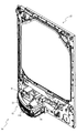
以下、本発明の実施形態について、添付図面を参照して説明する。まず、図1から図34を参照し、第1実施形態として、本発明をパチンコ遊技機(以下、単に「パチンコ機」という)10に適用した場合の一実施形態について説明する。図1は、第1実施形態におけるパチンコ機10の正面図であり、図2はパチンコ機10の遊技盤13の正面図であり、図3はパチンコ機10の背面図である。   Hereinafter, embodiments of the present invention will be described with reference to the accompanying drawings. First, with reference to FIG. 1 to FIG. 34, an embodiment in which the present invention is applied to a pachinko gaming machine (hereinafter, simply referred to as a “pachinko machine”) 10 will be described as a first embodiment. FIG. 1 is a front view of a pachinko machine 10 according to the first embodiment, FIG. 2 is a front view of a game board 13 of the pachinko machine 10, and FIG. 3 is a rear view of the pachinko machine 10.

図1に示すように、パチンコ機10は、略矩形状に組み合わせた木枠により外殻が形成される外枠11と、その外枠11と略同一の外形形状に形成され外枠11に対して開閉可能に支持された内枠12とを備えている。外枠11には、内枠12を支持するために正面視(図1参照)左側の上下2カ所に金属製のヒンジ18が取り付けられ、そのヒンジ18が設けられた側を開閉の軸として内枠12が正面手前側へ開閉可能に支持されている。   As shown in FIG. 1, the pachinko machine 10 includes an outer frame 11 having an outer shell formed by a wooden frame combined in a substantially rectangular shape, and an outer frame 11 having substantially the same outer shape as that of the outer frame 11. And an inner frame 12 that is openably and closably supported. To support the inner frame 12, metal hinges 18 are attached to the outer frame 11 at two upper and lower positions on the left side in front view (see FIG. 1), and the side provided with the hinge 18 serves as an opening / closing shaft. The frame 12 is supported to be openable and closable toward the front side.

内枠12には、多数の釘や入賞口63,64等を有する遊技盤13(図2参照)が裏面側から着脱可能に装着される。この遊技盤13の前面を球(遊技球)が流下することにより弾球遊技が行われる。なお、内枠12には、球を遊技盤13の前面領域に発射する球発射ユニット112a(図4参照)やその球発射ユニット112aから発射された球を遊技盤13の前面領域まで誘導する発射レール(図示せず)等が取り付けられている。   A game board 13 (see FIG. 2) having a large number of nails, winning holes 63, 64, etc. is detachably attached to the inner frame 12 from the back side. A ball game is performed by flowing a ball (game ball) on the front surface of the game board 13. In addition, in the inner frame 12, a ball launching unit 112a (see FIG. 4) that launches a ball to the front area of the game board 13 and a launch that guides the ball launched from the ball launching unit 112a to the front area of the game board 13. Rails (not shown) and the like are attached.

内枠12の前面側には、その前面上側を覆う前面枠14と、その下側を覆う下皿ユニット15とが設けられている。前面枠14及び下皿ユニット15を支持するために正面視(図1参照)左側の上下2カ所に金属製のヒンジ19が取り付けられ、そのヒンジ19が設けられた側を開閉の軸として前面枠14及び下皿ユニット15が正面手前側へ開閉可能に支持されている。なお、内枠12の施錠と前面枠14の施錠とは、シリンダ錠20の鍵穴21に専用の鍵を差し込んで所定の操作を行うことでそれぞれ解除される。   On the front side of the inner frame 12, a front frame 14 that covers the upper side of the front and a lower plate unit 15 that covers the lower side thereof are provided. In order to support the front frame 14 and the lower tray unit 15, metal hinges 19 are attached at two upper and lower positions on the left side in a front view (see FIG. 1), and the side on which the hinge 19 is provided serves as an opening / closing shaft. The lower plate unit 14 and the lower plate unit 15 are supported to be openable and closable toward the front side. The locking of the inner frame 12 and the locking of the front frame 14 are released by inserting a dedicated key into the keyhole 21 of the cylinder lock 20 and performing a predetermined operation.

前面枠14は、装飾用の樹脂部品や電気部品等を組み付けたものであり、その略中央部には略楕円形状に開口形成された窓部14cが設けられている。前面枠14の裏面側には2枚の板ガラスを有するガラスユニット16が配設され、そのガラスユニット16を介して遊技盤13の前面がパチンコ機10の正面側に視認可能となっている。   The front frame 14 is assembled with a decorative resin component, an electrical component, and the like, and a window portion 14c having a substantially elliptical opening is provided at a substantially central portion thereof. A glass unit 16 having two glass plates is arranged on the rear surface side of the front frame 14, and the front surface of the game board 13 can be visually recognized on the front surface side of the pachinko machine 10 through the glass unit 16.

前面枠14には、球を貯留する上皿17が前方へ張り出して上面を開放した略箱状に形成されており、この上皿17に賞球や貸出球などが排出される。上皿17の底面は正面視(図1参照)右側に下降傾斜して形成され、その傾斜により上皿17に投入された球が球発射ユニット112a(図4参照)へと案内される。また、上皿17の上面には、枠ボタン22が設けられている。この枠ボタン22は、例えば、第3図柄表示装置81(図2参照)で表示される演出のステージを変更したり、スーパーリーチの演出内容を変更したりする場合などに、遊技者により操作される。   On the front frame 14, an upper plate 17 for storing balls is formed in a substantially box shape with its front surface protruding and the upper surface opened, and prize balls, rental balls, etc. are discharged to the upper plate 17. The bottom surface of the upper plate 17 is formed to be inclined downward to the right in a front view (see FIG. 1), and the ball introduced into the upper plate 17 is guided to the ball firing unit 112a (see FIG. 4) by the inclination. A frame button 22 is provided on the upper surface of the upper plate 17. The frame button 22 is operated by the player, for example, when changing the stage of the effect displayed on the third symbol display device 81 (see FIG. 2) or when changing the effect contents of the super reach. It

前面枠14には、その周囲(例えばコーナー部分)に各種ランプ等の発光手段が設けられている。これら発光手段は、大当たり時や所定のリーチ時等における遊技状態の変化に応じて、点灯又は点滅することにより発光態様が変更制御され、遊技中の演出効果を高める役割を果たす。窓部14cの周縁には、LED等の発光手段を内蔵した電飾部29〜33が設けられている。パチンコ機10においては、これら電飾部29〜33が大当たりランプ等の演出ランプとして機能し、大当たり時やリーチ演出時等には内蔵するLEDの点灯や点滅によって各電飾部29〜33が点灯または点滅して、大当たり中である旨、或いは大当たり一歩手前のリーチ中である旨が報知される。また、前面枠14の正面視(図1参照)左上部には、LED等の発光手段が内蔵され賞球の払い出し中とエラー発生時とを表示可能な表示ランプ34が設けられている。   The front frame 14 is provided with light emitting means such as various lamps around the front frame 14 (for example, a corner portion). These light emitting means perform a change control of the light emitting mode by lighting or blinking according to a change in the game state at the time of a big hit or a predetermined reach, and play a role of enhancing the effect effect during the game. On the periphery of the window portion 14c, there are provided illumination portions 29 to 33 having a light emitting means such as an LED built therein. In the pachinko machine 10, these illumination parts 29 to 33 function as a production lamp such as a jackpot lamp, and when a jackpot or a reach production is performed, each illumination portion 29 to 33 is turned on by turning on or blinking the built-in LED. Alternatively, it blinks to notify that the jackpot is in progress, or that the reach before the jackpot is in progress. Further, in the upper left portion of the front frame 14 when viewed from the front (see FIG. 1), a light emitting means such as an LED is provided and a display lamp 34 capable of displaying during payout of a prize ball and when an error occurs is provided.

また、右側の電飾部32下側には、前面枠14の裏面側を視認できるように裏面側より透明樹脂を取り付けて小窓35が形成され、遊技盤13前面の貼着スペースK1(図2参照)に貼付される証紙等がパチンコ機10の前面から視認可能とされている。また、パチンコ機10においては、より煌びやかさを醸し出すために、電飾部29〜33の周りの領域にクロムメッキを施したABS樹脂製のメッキ部材36が取り付けられている。   In addition, a small window 35 is formed on the lower side of the illumination section 32 on the right side by attaching a transparent resin from the back side so that the back side of the front frame 14 can be visually recognized, and a pasting space K1 on the front side of the game board 13 (Fig. The certificate or the like attached to (see 2) is visible from the front of the pachinko machine 10. Further, in the pachinko machine 10, a plating member 36 made of ABS resin, which is plated with chrome, is attached to a region around the electric decorations 29 to 33 in order to bring out more glitter.

窓部14cの下方には、貸球操作部40が配設されている。貸球操作部40には、度数表示部41と、球貸しボタン42と、返却ボタン43とが設けられている。パチンコ機10の側方に配置されるカードユニット(球貸しユニット)(図示せず)に紙幣やカード等を投入した状態で貸球操作部40が操作されると、その操作に応じて球の貸出が行われる。具体的には、度数表示部41はカード等の残額情報が表示される領域であり、内蔵されたLEDが点灯して残額情報として残額が数字で表示される。球貸しボタン42は、カード等(記録媒体)に記録された情報に基づいて貸出球を得るために操作されるものであり、カード等に残額が存在する限りにおいて貸出球が上皿17に供給される。返却ボタン43は、カードユニットに挿入されたカード等の返却を求める際に操作される。なお、カードユニットを介さずに球貸し装置等から上皿17に球が直接貸し出されるパチンコ機、いわゆる現金機では貸球操作部40が不要となるが、この場合には、貸球操作部40の設置部分に飾りシール等を付加して部品構成は共通のものとしても良い。カードユニットを用いたパチンコ機と現金機との共通化を図ることができる。   A ball rental operating unit 40 is disposed below the window 14c. The ball rental operation section 40 is provided with a frequency display section 41, a ball lending button 42, and a return button 43. When the ball rental operation unit 40 is operated in a state where banknotes, cards, etc. are inserted into a card unit (ball lending unit) (not shown) arranged on the side of the pachinko machine 10, the ball is operated according to the operation. Lending is done. Specifically, the frequency display unit 41 is an area in which the remaining amount information of a card or the like is displayed, and the built-in LED is turned on to display the remaining amount as a number as the remaining amount information. The ball lending button 42 is operated to obtain a loan ball based on information recorded on a card or the like (recording medium), and the loan ball is supplied to the upper plate 17 as long as the card or the like has a balance. To be done. The return button 43 is operated when requesting the return of a card or the like inserted in the card unit. It should be noted that the ball rental operation unit 40 is not necessary in a so-called cash machine, which is a pachinko machine in which balls are lent directly to the upper plate 17 from a ball lending device or the like without a card unit, but in this case, the ball rental operation unit 40 is used. It is also possible to add a decorative seal or the like to the installation portion of to make the parts configuration common. It is possible to share a pachinko machine using a card unit with a cash machine.

上皿17の下側に位置する下皿ユニット15には、その左側に上皿17に貯留しきれなかった球を貯留するための下皿50が上面を開放した略箱状に形成されている。下皿50の右側には、球を遊技盤13の前面へ打ち込むために遊技者によって操作される操作ハンドル51が配設される。   In the lower plate unit 15 located below the upper plate 17, a lower plate 50 for storing balls that could not be stored in the upper plate 17 is formed on the left side of the lower plate unit 15 in a substantially box-like shape with an open upper surface. .. On the right side of the lower plate 50, an operation handle 51 operated by the player to drive the ball into the front surface of the game board 13 is provided.

操作ハンドル51の内部には、球発射ユニット112aの駆動を許可するためのタッチセンサ51aと、押下操作している期間中には球の発射を停止する発射停止スイッチ51bと、操作ハンドル51の回動操作量(回動位置)を電気抵抗の変化により検出する可変抵抗器(図示せず)などが内蔵されている。操作ハンドル51が遊技者によって右回りに回動操作されると、タッチセンサ51aがオンされると共に可変抵抗器の抵抗値が回動操作量に対応して変化し、その可変抵抗器の抵抗値に対応した強さ(発射強度)で球が発射され、これにより遊技者の操作に対応した飛び量で遊技盤13の前面へ球が打ち込まれる。また、操作ハンドル51が遊技者により操作されていない状態においては、タッチセンサ51aおよび発射停止スイッチ51bがオフとなっている。   Inside the operation handle 51, a touch sensor 51a for permitting the driving of the ball firing unit 112a, a firing stop switch 51b for stopping the firing of the ball during the pressing operation, and a rotation of the operation handle 51. A variable resistor (not shown) for detecting a dynamic operation amount (rotational position) by a change in electric resistance is built in. When the operation handle 51 is rotated clockwise by the player, the touch sensor 51a is turned on and the resistance value of the variable resistor changes in accordance with the rotation operation amount, and the resistance value of the variable resistor is changed. The ball is fired with a strength (firing strength) corresponding to, and thus the ball is driven into the front surface of the game board 13 with a jump amount corresponding to the operation of the player. Further, when the operation handle 51 is not operated by the player, the touch sensor 51a and the firing stop switch 51b are off.

下皿50の正面下方部には、下皿50に貯留された球を下方へ排出する際に操作するための球抜きレバー52が設けられている。この球抜きレバー52は、常時、正面方向に付勢されており、その付勢に抗して背面方向へスライドさせることにより、下皿50の底面に形成された底面口が開口して、その底面口から球が自然落下して排出される。この球抜きレバー54bの操作は、通常、下皿50の下方に下皿50から排出された球を受け取る箱(一般に「千両箱」と称される)を置いた状態で行われる。   At the lower part of the front surface of the lower plate 50, a ball removing lever 52 for operating when discharging the balls stored in the lower plate 50 downward is provided. This ball-pulling lever 52 is always biased in the front direction, and by sliding it in the back direction against the bias, the bottom opening formed on the bottom surface of the lower plate 50 is opened, and The sphere spontaneously falls from the bottom opening and is discharged. The operation of the ball removing lever 54b is usually performed with a box (generally referred to as a "thousand box") placed below the lower plate 50 for receiving the balls discharged from the lower plate 50.

図2に示すように、遊技盤13は、正面視略正方形状に切削加工したベース板60に、球案内用の多数の釘(図示せず)や風車の他、レール61,62、一般入賞口63、第1入賞口64、第2入賞口640、可変入賞装置65、スルーゲート67、可変表示装置ユニット80等を組み付けて構成され、その周縁部が内枠12(図1参照)の裏面側に取り付けられる。ベース板60は光透過性の樹脂材料からなり、その正面側からベース板60の背面側に配設された各種構造体を遊技者に視認させることが可能に形成される。一般入賞口63、第1入賞口64、第2入賞口640、可変入賞装置65、可変表示装置ユニット80は、ルータ加工によってベース板60に形成された貫通穴に配設され、遊技盤13の前面側からタッピングネジ等により固定されている。   As shown in FIG. 2, the game board 13 has a base plate 60 cut into a substantially square shape in a front view, a large number of nails (not shown) for guiding a ball, a windmill, rails 61 and 62, a general prize. The mouth 63, the first winning opening 64, the second winning opening 640, the variable winning device 65, the through gate 67, the variable display device unit 80 and the like are assembled, and the peripheral portion thereof is the back surface of the inner frame 12 (see FIG. 1). Mounted on the side. The base plate 60 is made of a light-transmissive resin material, and is formed so that the player can visually recognize various structural bodies arranged on the back side of the base plate 60 from the front side. The general winning opening 63, the first winning opening 64, the second winning opening 640, the variable winning device 65, and the variable display device unit 80 are arranged in through holes formed in the base plate 60 by router processing, and are provided on the game board 13. It is fixed by tapping screws from the front side.

遊技盤13の前面中央部分は、前面枠14の窓部14c(図1参照)を通じて内枠12の前面側から視認することができる。以下に、主に図2を参照して、遊技盤13の構成について説明する。   The front center portion of the game board 13 can be viewed from the front side of the inner frame 12 through the window 14c (see FIG. 1) of the front frame 14. The configuration of the game board 13 will be described below mainly with reference to FIG.

遊技盤13の前面には、帯状の金属板を略円弧状に屈曲加工して形成した外レール62が植立され、その外レール62の内側位置には外レール62と同様に帯状の金属板で形成した円弧状の内レール61が植立される。この内レール61と外レール62とにより遊技盤13の前面外周が囲まれ、遊技盤13とガラスユニット16(図1参照)とにより前後が囲まれることにより、遊技盤13の前面には、球の挙動により遊技が行われる遊技領域が形成される。遊技領域は、遊技盤13の前面であって2本のレール61,62とレール間を繋ぐ樹脂製の外縁部材73とにより区画して形成される領域(入賞口等が配設され、発射された球が流下する領域)である。   On the front surface of the game board 13, an outer rail 62 formed by bending a strip-shaped metal plate into a substantially arc shape is planted, and inside the outer rail 62, a strip-shaped metal plate similar to the outer rail 62. The arc-shaped inner rail 61 formed in step 1 is planted. The inner rail 61 and the outer rail 62 surround the outer periphery of the front surface of the game board 13, and the front and rear are surrounded by the game board 13 and the glass unit 16 (see FIG. 1), so that the front surface of the game board 13 has a ball. A game area where a game is played is formed by the behavior of. The game area is a front surface of the game board 13 and is defined by two rails 61 and 62 and a resin outer edge member 73 that connects the rails (a winning opening or the like is provided and fired). The area where the sphere flows down).

2本のレール61,62は、球発射ユニット112a(図4参照)から発射された球を遊技盤13上部へ案内するために設けられたものである。内レール61の先端部分(図2の左上部)には戻り球防止部材68が取り付けられ、一旦、遊技盤13の上部へ案内された球が再度球案内通路内に戻ってしまうといった事態が防止される。外レール62の先端部(図2の右上部)には、球の最大飛翔部分に対応する位置に返しゴム69が取り付けられ、所定以上の勢いで発射された球は、返しゴム69に当たって、勢いが減衰されつつ中央部側へ跳ね返される。   The two rails 61 and 62 are provided to guide the ball fired from the ball firing unit 112a (see FIG. 4) to the upper part of the game board 13. A return ball prevention member 68 is attached to the tip portion (upper left portion of FIG. 2) of the inner rail 61 to prevent the situation where the ball once guided to the upper part of the game board 13 returns to the ball guide passage again. To be done. A return rubber 69 is attached to the tip of the outer rail 62 (the upper right portion in FIG. 2) at a position corresponding to the maximum flight portion of the ball, and the ball fired with a momentum higher than a predetermined value hits the return rubber 69 to generate momentum. Is attenuated and bounces back toward the center.

遊技領域の正面視左側下部(図2の左側下部)には、発光手段である複数のLED及び7セグメント表示器を備える第1図柄表示装置37A,37Bが配設されている。第1図柄表示装置37A,37Bは、主制御装置110(図4参照)で行われる各制御に応じた表示がなされるものであり、主にパチンコ機10の遊技状態の表示が行われる。本実施形態では、第1図柄表示装置37A,37Bは、球が、第1入賞口64へ入賞したか、第2入賞口640へ入賞したかに応じて使い分けられるように構成されている。具体的には、球が、第1入賞口64へ入賞した場合には、第1図柄表示装置37Aが作動し、一方で、球が、第2入賞口640へ入賞した場合には、第1図柄表示装置37Bが作動するように構成されている。   The first symbol display device 37A, 37B including a plurality of LEDs, which are light emitting means, and a 7-segment display is disposed on the lower left side in the front view of the game area (lower left side in FIG. 2). The first symbol display devices 37A and 37B are displays according to each control performed by the main control device 110 (see FIG. 4), and mainly display the gaming state of the pachinko machine 10. In the present embodiment, the first symbol display devices 37A and 37B are configured to be used properly according to whether the ball has won the first winning opening 64 or the second winning opening 640. Specifically, when the ball wins the first winning opening 64, the first symbol display device 37A operates, while on the other hand, when the ball wins the second winning opening 640, the first The symbol display device 37B is configured to operate.

また、第1図柄表示装置37A,37Bは、LEDにより、パチンコ機10が確変中か時短中か通常中であるかを点灯状態により示したり、変動中であるか否かを点灯状態により示したり、停止図柄が確変大当たりに対応した図柄か普通大当たりに対応した図柄か外れ図柄であるかを点灯状態により示したり、保留球数を点灯状態により示すと共に、7セグメント表示装置により、大当たり中のラウンド数やエラー表示を行う。なお、複数のLEDは、それぞれのLEDの発光色(例えば、赤、緑、青)が異なるよう構成され、その発光色の組み合わせにより、少ないLEDでパチンコ機10の各種遊技状態を示唆することができる。   Further, the first symbol display device 37A, 37B, by using an LED, indicates whether the pachinko machine 10 is in the process of positive change, time saving, or normal by a lighting state, or indicates whether it is changing by a lighting state. , The stop symbol indicates whether it is a symbol corresponding to the probability variation jackpot, a symbol corresponding to the normal jackpot, or a symbol that is out of sync with a lighting state, and the number of reserved balls is indicated by a lighting state, and a 7-segment display device provides a round of jackpots. Display numbers and errors. In addition, the plurality of LEDs are configured such that the respective LEDs have different emission colors (for example, red, green, and blue), and the combination of the emission colors can suggest various game states of the pachinko machine 10 with a small number of LEDs. it can.

尚、本パチンコ機10では、第1入賞口64及び第2入賞口640へ入賞があったことを契機として抽選が行われる。パチンコ機10は、その抽選において、大当たりか否かの当否判定(大当たり抽選)を行うと共に、大当たりと判定した場合はその大当たり種別の判定も行う。ここで判定される大当たり種別としては、15R確変大当たり、4R確変大当たり、15R通常大当たりが用意されている。第1図柄表示装置37A,37Bには、変動終了後の停止図柄として抽選の結果が大当たりであるか否かが示されるだけでなく、大当たりである場合はその大当たり種別に応じた図柄が示される。   In the pachinko machine 10, the lottery is performed when the first winning opening 64 and the second winning opening 640 are won. In the lottery, the pachinko machine 10 determines whether or not it is a big hit (big hit lottery), and when it is a big hit, also makes a determination of the big hit type. As the types of jackpots determined here, 15R certainty jackpots, 4R certainty jackpots, and 15R regular jackpots are prepared. The first symbol display devices 37A, 37B not only show whether or not the result of the lottery is a big hit as a stop symbol after the end of variation, but if it is a big hit, a symbol according to the big hit type is shown. ..

ここで、「15R確変大当たり」とは、最大ラウンド数が15ラウンドの大当たりの後に高確率状態へ移行する確変大当たりのことであり、「4R確変大当たり」とは、最大ラウンド数が4ラウンドの大当たりの後に高確率状態へ移行する確変大当たりのことである。また、「15R通常大当たり」は、最大ラウンド数が15ラウンドの大当たりの後に、低確率状態へ移行すると共に、所定の変動回数の間(例えば、100変動回数)は時短状態となる大当たりのことである。   Here, the "15R probability variation jackpot" is a probability variation jackpot in which the maximum round number shifts to a high probability state after the 15 round jackpot, and the "4R probability variation jackpot" is a jackpot with a maximum round number of 4 rounds. It is a probability change jackpot that shifts to a high probability state after. In addition, "15R normal jackpot" is a jackpot that shifts to a low-probability state after the jackpot with the maximum round number of 15 rounds and becomes a shortened state for a predetermined number of fluctuations (for example, 100 fluctuations). is there.

また、「高確率状態」とは、大当たり終了後に付加価値としてその後の大当たり確率がアップした状態、いわゆる確率変動中(確変中)の時をいい、換言すれば、特別遊技状態へ移行し易い遊技の状態のことである。本実施形態における高確率状態(確変中)は、後述する第2図柄の当たり確率がアップして第2入賞口640へ球が入賞し易い遊技の状態を含む。「低確率状態」とは、確変中でない時をいい、大当たり確率が通常の状態、即ち、確変の時より大当たり確率が低い状態をいう。また、「低確率状態」のうちの時短状態(時短中)とは、大当たり確率が通常の状態であると共に、大当たり確率がそのままで第2図柄の当たり確率のみがアップして第2入賞口640へ球が入賞し易い遊技の状態のことをいう。一方、パチンコ機10が通常中とは、確変中でも時短中でもない遊技の状態(大当たり確率も第2図柄の当たり確率もアップしていない状態)である。   The "high probability state" means a state in which the subsequent jackpot probability increases as an added value after the jackpot ends, that is, when the probability is changing (probably changing), in other words, a game that easily transitions to a special game state. Is the state of. The high-probability state (probably changing) in the present embodiment includes a game state in which the probability of hitting a second symbol, which will be described later, increases and the ball easily wins the second winning opening 640. The "low probability state" refers to a state in which the probability of jackpot is not in progress, and the jackpot probability is normal, that is, a state in which the jackpot probability is lower than that in the probability change. In addition, the time saving state (time saving time) in the “low probability state” is a state where the jackpot probability is a normal state, the jackpot probability remains the same, and only the hit probability of the second symbol is increased to the second winning opening 640. It is a game state where the ball is easy to win. On the other hand, when the pachinko machine 10 is in the normal state, it is a state of the game which is neither probable change nor short time (a state where neither the jackpot probability nor the hit probability of the second symbol is improved).

確変中や時短中は、第2図柄の当たり確率がアップするだけではなく、第2入賞口640に付随する電動役物640aが開放される時間も変更され、通常中と比して長い時間が設定される。電動役物640aが開放された状態(開放状態)にある場合は、その電動役物640aが閉鎖された状態(閉鎖状態)にある場合と比して、第2入賞口640へ球が入賞しやすい状態となる。よって、確変中や時短中は、第2入賞口640へ球が入賞し易い状態となり、大当たり抽選が行われる回数を増やすことができる。   During the probability change or shortening of time, not only the probability of hitting the second symbol is increased, but also the time for which the electric accessory 640a associated with the second winning opening 640 is opened is changed, which is a long time compared to the normal time. Is set. When the electric accessory 640a is in an open state (open state), a ball is won in the second winning opening 640, as compared with the case where the electric accessory 640a is in a closed state (closed state). It will be in an easy state. Therefore, during the probability change or shortening of time, it becomes easy for the ball to win the second winning opening 640, and the number of times the jackpot lottery is performed can be increased.

なお、確変中や時短中において、第2入賞口640に付随する電動役物640aの開放時間を変更するのではなく、または、その開放時間を変更することに加えて、1回の当たりで電動役物640aが開放する回数を通常中よりも増やす変更を行うものとしてもよい。また、確変中や時短中において、第2図柄の当たり確率は変更せず、第2入賞口640に付随する電動役物640aが開放される時間および1回の当たりで電動役物640aが開放する回数の少なくとも一方を変更するものとしてもよい。また、確変中や時短中において、第2入賞口640に付随する電動役物640aが開放される時間や、1回の当たりで電動役物640aを開放する回数はせず、第2図柄の当たり確率だけを、通常中と比してアップするよう変更するものであってもよい。   It should be noted that, during the probable change or during the shortening of time, the opening time of the electric accessory 640a associated with the second winning opening 640 is not changed, or in addition to changing the opening time, electric power is generated by one hit. The number of times that the accessory 640a is opened may be changed to be larger than that during normal operation. Also, during the probability change or shortening time, the winning probability of the second symbol is not changed, and the electric accessory 640a is opened at the time and once when the electric accessory 640a associated with the second winning opening 640 is opened. At least one of the numbers of times may be changed. Also, during the probability change or shortening of time, the time when the electric accessory 640a associated with the second winning opening 640 is opened or the number of times the electric accessory 640a is opened per hit is not adjusted, and the second symbol is hit. Only the probability may be changed so as to be higher than that in the normal state.

遊技領域には、球が入賞することにより5個から15個の球が賞球として払い出される複数の一般入賞口63が配設されている。また、遊技領域の中央部分には、可変表示装置ユニット80が配設されている。可変表示装置ユニット80には、第1入賞口64及び第2入賞口640への入賞(始動入賞)をトリガとして、第1図柄表示装置37A,37Bにおける変動表示と同期させながら、第3図柄の変動表示を行う液晶ディスプレイ(以下単に「表示装置」と略す)で構成された第3図柄表示装置81と、スルーゲート67の球の通過をトリガとして第2図柄を変動表示するLEDで構成される第2図柄表示装置(図示せず)とが設けられている。   In the game area, there are arranged a plurality of general winning openings 63 in which 5 to 15 balls are paid out as prize balls when the balls are won. A variable display device unit 80 is arranged in the center of the game area. In the variable display device unit 80, the winning of the first winning opening 64 and the second winning opening 640 (starting winning) is used as a trigger, while synchronizing with the variable display in the first symbol displaying devices 37A and 37B, It is composed of a third symbol display device 81 composed of a liquid crystal display (hereinafter simply referred to as “display device”) that performs variable display, and an LED that variably displays the second symbol triggered by passage of the ball of the through gate 67. A second symbol display device (not shown) is provided.

また、可変表示装置ユニット80には、第3図柄表示装置81の外周を囲むようにして、センターフレーム86が配設されている。このセンターフレーム86の中央に開口される開口部から第3図柄表示装置81が視認可能とされる。   Further, the variable display device unit 80 is provided with a center frame 86 so as to surround the outer periphery of the third symbol display device 81. The third symbol display device 81 is visible through an opening formed in the center of the center frame 86.

第3図柄表示装置81は9インチサイズの大型の液晶ディスプレイで構成されるものであり、表示制御装置114(図4参照)によって表示内容が制御されることにより、例えば上、中及び下の3つの図柄列が表示される。各図柄列は複数の図柄(第3図柄)によって構成され、これらの第3図柄が図柄列毎に横スクロールして第3図柄表示装置81の表示画面上にて第3図柄が可変表示されるようになっている。本実施形態の第3図柄表示装置81は、主制御装置110(図4参照)の制御に伴った遊技状態の表示が第1図柄表示装置37A,37Bで行われるのに対して、その第1図柄表示装置37A,37Bの表示に応じた装飾的な表示を行うものである。なお、表示装置に代えて、例えばリール等を用いて第3図柄表示装置81を構成するようにしても良い。   The third symbol display device 81 is composed of a large 9-inch liquid crystal display, and the display content is controlled by the display control device 114 (see FIG. 4), for example, upper, middle and lower 3 Two symbol columns are displayed. Each symbol row is composed of a plurality of symbols (third symbol), and the third symbol is variably displayed on the display screen of the third symbol display device 81 by horizontally scrolling the third symbol for each symbol column. It is like this. In the third symbol display device 81 of the present embodiment, the display of the game state accompanied by the control of the main controller 110 (see FIG. 4) is performed on the first symbol display devices 37A, 37B, whereas the first The decorative display corresponding to the display of the symbol display devices 37A and 37B is performed. Instead of the display device, for example, a reel or the like may be used to configure the third symbol display device 81.

第2図柄表示装置は、球がスルーゲート67を通過する毎に表示図柄(第2図柄(図示せず))としての「○」の図柄と「×」の図柄とを所定時間交互に点灯させる変動表示を行うものである。パチンコ機10では、球がスルーゲート67を通過したことが検出されると、当たり抽選が行われる。その当たり抽選の結果、当たりであれば、第2図柄表示装置において、第2図柄の変動表示後に「○」の図柄が停止表示される。また、当たり抽選の結果、外れであれば、第2図柄表示装置において、第3図柄の変動表示後に「×」の図柄が停止表示される。   The second symbol display device alternately turns on the symbol "o" and the symbol "x" as the display symbol (second symbol (not shown)) every time the ball passes through the through gate 67 for a predetermined time. It is a variable display. In the pachinko machine 10, when it is detected that the ball has passed through the through gate 67, a winning lottery is performed. As a result of the winning lottery, if it is a win, the symbol “◯” is stopped and displayed after the variable display of the second symbol on the second symbol display device. In addition, as a result of the winning lottery, if it is out, the symbol "x" is stopped and displayed after the variable display of the third symbol on the second symbol display device.

パチンコ機10は、第2図柄表示装置における変動表示が所定図柄(本実施形態においては「○」の図柄)で停止した場合に、第2入賞口640に付随された電動役物640aが所定時間だけ作動状態となる(開放される)よう構成されている。   In the pachinko machine 10, when the variable display on the second symbol display device is stopped by the predetermined symbol (in the present embodiment, the symbol "○"), the electric accessory 640a attached to the second winning opening 640 is for a predetermined time. It is configured to be activated (opened) only.

第2図柄の変動表示にかかる時間は、遊技状態が通常中の場合よりも、確変中または時短中の方が短くなるように設定される。これにより、確変中および時短中は、第2図柄の変動表示が短い時間で行われるので、当たり抽選を通常中よりも多く行うことができる。よって、当たり抽選において当たりとなる機会が増えるので、第2入賞口640の電動役物640aが開放状態となる機会を遊技者に多く与えることができる。よって、確変中および時短中は、第2入賞口640へ球が入賞しやすい状態とすることができる。   The time required for the variable display of the second symbol is set to be shorter during the probability change or during the time saving than when the game state is normal. As a result, during the probability change and the time reduction, the variable display of the second symbol is performed in a short time, so that the winning lottery can be performed more than usual. Therefore, the chances of winning in the winning lottery increase, so that the player can be given many opportunities to open the electric auditors product 640a of the second winning opening 640. Therefore, the ball can easily enter the second winning opening 640 during the probability change and the time saving.

なお、確変中または時短中において、当たり確率を高める、1回に当たりに対する電動役物640aの開放時間や開放回数を増やすなど、その他の方法によっても、確変中または時短中に第2入賞口640へ球が入賞しやすい状態としている場合は、第2図柄の変動表示にかかる時間を遊技状態にかかわらず一定としてもよい。一方、第2図柄の変動表示にかかる時間を、確変中または時短中において通常中よりも短く設定する場合は、当たり確率を遊技状態にかかわらず一定にしてもよいし、また、1回の当たりに対する電動役物640aの開放時間や開放回数を遊技状態にかかわらず一定にしてもよい。   In addition, during the probability change or time saving, the probability of winning is increased, and the opening time and the number of times of opening the electric accessory 640a per hit are increased. When the ball is in a state of easy winning, the time required for variable display of the second symbol may be constant regardless of the gaming state. On the other hand, when the time required for the variable display of the second symbol is set to be shorter than the normal time during the probability variation or the time saving, the winning probability may be constant regardless of the gaming state, or one hit. The opening time and the number of times of opening the electric accessory 640a may be constant regardless of the game state.

スルーゲート67は、可変表示装置ユニット80の下側の領域における右方において遊技盤に組み付けられ、遊技盤に発射された球のうち、遊技盤の右方を流下する球の一部が通過可能に構成されている。スルーゲート67を球が通過すると、第2図柄の当たり抽選が行われる。当たり抽選の後、第2図柄表示装置にて変動表示を行い、当たり抽選の結果が当たりであれば、変動表示の停止図柄として「○」の図柄を表示し、当たり抽選の結果が外れであれば、変動表示の停止図柄として「×」の図柄を表示する。   The through gate 67 is attached to the game board on the right side in the lower region of the variable display device unit 80, and among the balls emitted to the game board, a part of the ball flowing down on the right side of the game board can pass through. Is configured. When the ball passes through the through gate 67, a winning lottery for the second symbol is performed. After the winning lottery, a variable display is performed on the second symbol display device, and if the result of the winning lottery is a win, the symbol "○" is displayed as a stop symbol of the variable display and the result of the winning lottery is out For example, the symbol "x" is displayed as the variable display stop symbol.

球のスルーゲート67の通過回数は、合計で最大4回まで保留され、その保留球数が上述した第1図柄表示装置37A,37Bにより表示されると共に第2図柄保留ランプ(図示せず)においても点灯表示される。第2図柄保留ランプは、最大保留数分の4つ設けられ、第3図柄表示装置81の下方に左右対称に配設されている。   The number of times the ball passes through the through gate 67 is held up to a maximum of four times in total, and the number of holding balls is displayed by the above-mentioned first symbol display devices 37A, 37B and at the second symbol holding lamp (not shown). Is also lit. Two second symbol holding lamps are provided for the maximum number of holdings, and are arranged symmetrically below the third symbol display device 81.

なお、第2図柄の変動表示は、本実施形態のように、第2図柄表示装置において複数のランプの点灯と非点灯を切り換えることにより行うものの他、第1図柄表示装置37A,37B及び第3図柄表示装置81の一部を使用して行うようにしても良い。同様に、第2図柄保留ランプの点灯を第3図柄表示装置81の一部で行うようにしても良い。また、スルーゲート67の球の通過に対する最大保留球数は4回に限定されるものでなく、3回以下、又は、5回以上の回数(例えば、8回)に設定しても良い。また、スルーゲート67の組み付け数は1つに限定されるものではなく、複数(例えば、2つ)であっても良い。また、スルーゲート67の組み付け位置は可変表示装置ユニット80の右方に限定されるものではなく、例えば、可変表示装置ユニット80の左方でも良い。また、第1図柄表示装置37A,37Bにより保留球数が示されるので、第2図柄保留ランプにより点灯表示を行わないものとしてもよい。   The variable display of the second symbol is performed by switching lighting and non-lighting of a plurality of lamps in the second symbol display device as in the present embodiment, as well as the first symbol display devices 37A, 37B and the third. Alternatively, a part of the symbol display device 81 may be used. Similarly, the second symbol holding lamp may be turned on by a part of the third symbol display device 81. Further, the maximum number of retained balls for the passage of the ball through the through gate 67 is not limited to four times, and may be set to three times or less, or five times or more (e.g., eight times). Further, the number of through gates 67 to be assembled is not limited to one, but may be plural (for example, two). Further, the mounting position of the through gate 67 is not limited to the right side of the variable display device unit 80, and may be, for example, the left side of the variable display device unit 80. Further, since the number of reserved balls is indicated by the first symbol display devices 37A and 37B, it is possible not to perform the lighting display by the second symbol reservation lamp.

可変表示装置ユニット80の下方には、球が入賞し得る第1入賞口64が配設されている。この第1入賞口64へ球が入賞すると遊技盤13の裏面側に設けられる第1入賞口スイッチ(図示せず)がオンとなり、その第1入賞口スイッチのオンに起因して主制御装置110(図4参照)で大当たりの抽選がなされ、その抽選結果に応じた表示が第1図柄表示装置37Aで示される。   Below the variable display device unit 80, a first winning opening 64 through which a ball can be won is arranged. When a ball wins the first winning opening 64, a first winning opening switch (not shown) provided on the back side of the game board 13 is turned on, and the main controller 110 is caused by the turning on of the first winning opening switch. (Refer to FIG. 4) A big hit lottery is made, and a display corresponding to the lottery result is shown on the first symbol display device 37A.

一方、第1入賞口64の正面視右方には、球が入賞し得る第2入賞口640が配設されている。この第2入賞口640へ球が入賞すると遊技盤13の裏面側に設けられる第2入賞口スイッチ(図示せず)がオンとなり、その第2入賞口スイッチのオンに起因して主制御装置110(図4参照)で大当たりの抽選がなされ、その抽選結果に応じた表示が第1図柄表示装置37Bで示される。   On the other hand, on the right side of the first winning opening 64 in a front view, a second winning opening 640 through which a ball can win is arranged. When a ball wins the second winning opening 640, a second winning opening switch (not shown) provided on the back side of the game board 13 is turned on, and the main controller 110 is caused by the turning on of the second winning opening switch. (Refer to FIG. 4) A big hit lottery is made, and a display corresponding to the lottery result is shown on the first symbol display device 37B.

また、第1入賞口64および第2入賞口640は、それぞれ、球が入賞すると5個の球が賞球として払い出される入賞口の1つにもなっている。なお、本実施形態においては、第1入賞口64へ球が入賞した場合に払い出される賞球数と第2入賞口640へ球が入賞した場合に払い出される賞球数とを同じに構成したが、第1入賞口64へ球が入賞した場合に払い出される賞球数と第2入賞口640へ球が入賞した場合に払い出される賞球数とを異なる数、例えば、第1入賞口64へ球が入賞した場合に払い出される賞球数を3個とし、第2入賞口640へ球が入賞した場合に払い出される賞球数を5個として構成してもよい。   In addition, each of the first winning opening 64 and the second winning opening 640 is also one of the winning openings through which five balls are paid out as prize balls when a ball wins. In addition, in the present embodiment, the number of prize balls paid out when the balls are won in the first winning opening 64 and the number of prize balls paid out when the balls are won in the second winning opening 640 are the same. , The number of prize balls paid out when a ball is won in the first winning opening 64 and the number of prize balls paid out when a ball is winning in the second winning opening 640, for example, a ball to the first winning opening 64 The number of prize balls to be paid out when a prize is won may be set to 3, and the number of prize balls to be paid out when a ball is won to the second winning port 640 may be set to 5.

第2入賞口640には電動役物640aが付随されている。この電動役物640aは開閉可能に構成されており、通常は電動役物640aが閉鎖状態(縮小状態)となって、球が第2入賞口640へ入賞しにくい状態となっている。一方、スルーゲート67への球の通過を契機として行われる第2図柄の変動表示の結果、「○」の図柄が第2図柄表示装置に表示された場合、電動役物640aが開放状態(拡大状態)となり、球が第2入賞口640へ入賞しやすい状態となる。   An electric accessory 640a is attached to the second winning opening 640. The electric accessory 640a is configured to be openable and closable, and normally the electric accessory 640a is in a closed state (reduced state), and it is difficult for a ball to enter the second winning opening 640. On the other hand, as a result of the variable display of the second symbol which is carried out upon the passage of the ball to the through gate 67, when the symbol "○" is displayed on the second symbol display device, the electric accessory 640a is in the open state (enlarged). (State), and the ball is in a state where it is easy to enter the second winning opening 640.

上述した通り、確変中および時短中は、通常中と比して第2図柄の当たり確率が高く、また、第2図柄の変動表示にかかる時間も短いので、第2図柄の変動表示において「○」の図柄が表示され易くなって、電動役物640aが開放状態(拡大状態)となる回数が増える。更に、確変中および時短中は、電動役物640aが開放される時間も、通常中より長くなる。よって、確変中および時短中は、通常時と比して、第2入賞口640へ球が入賞しやすい状態を作ることができる。   As described above, the probability of hitting the second symbol is higher than that in the normal state during the probability change and the shortening of the time period, and the time required for the variable display of the second symbol is short, so that in the variable display of the second symbol, “○” is displayed. Is easily displayed, and the number of times the electric accessory 640a is in the open state (enlarged state) increases. Further, the time during which the electric accessory 640a is opened during the probability change and the shortening of time is longer than that during the normal time. Therefore, during the probability change and the shortened working hours, it is possible to create a state in which the balls are more likely to win the second winning opening 640 than in the normal time.

ここで、第1入賞口64に球が入賞した場合と第2入賞口640へ球が入賞した場合とで、大当たりとなる確率は、低確率状態であっても高確率状態でも同一である。しかしながら、大当たりとなった場合に選定される大当たりの種別として15R確変大当たりとなる確率は、第2入賞口640へ球が入賞した場合のほうが第1入賞口64へ球が入賞した場合よりも高く設定されている。一方、第1入賞口64は、第2入賞口640にあるような電動役物は有しておらず、球が常時入賞可能な状態となっている。   Here, the probability of being a big hit is the same in both the low-probability state and the high-probability state, when the ball wins the first winning opening 64 and when the ball wins the second winning opening 640. However, when the jackpot is a big jackpot, the probability that the 15R probability variation jackpot will be selected as a jackpot type is higher when the ball is won at the second winning port 640 than when the ball is won at the first winning port 64. It is set. On the other hand, the first winning opening 64 does not have an electric accessory as in the second winning opening 640, and the ball is always ready for winning.

よって、通常中においては、第2入賞口640に付随する電動役物が閉鎖状態にある場合が多く、第2入賞口640に入賞しづらいので、電動役物のない第1入賞口64へ向けて、可変表示装置ユニット80の左方を球が通過するように球を発射し(所謂「左打ち」)、第1入賞口64への入賞によって大当たり抽選の機会を多く得て、大当たりとなることを狙った方が、遊技者にとって有利となる。   Therefore, during normal operation, the electric winning object associated with the second winning opening 640 is often in a closed state, and it is difficult to win the second winning opening 640. Then, the ball is fired so that the ball passes the left side of the variable display device unit 80 (so-called "left hitting"), and a lot of chances of the big hit lottery are obtained by winning the prize at the first winning a prize port 64, which is a big hit. It is advantageous for the player to aim for that.

一方、確変中や時短中は、スルーゲート67に球を通過させることで、第2入賞口640に付随する電動役物640aが開放状態となりやすく、第2入賞口640に入賞しやすい状態であるので、第2入賞口640へ向けて、可変表示装置80の右方を球が通過するように球を発射し(所謂「右打ち」)、スルーゲート67を通過させて電動役物を開放状態にすると共に、第2入賞口640への入賞によって15R確変大当たりとなることを狙った方が、遊技者にとって有利となる。   On the other hand, during the probability change or shortening of time, by passing the ball through the through gate 67, the electric accessory 640a associated with the second winning port 640 is likely to be opened, and the second winning port 640 is easily won. Therefore, toward the second winning port 640, the ball is fired so that the ball passes the right side of the variable display device 80 (so-called "right hitting"), and the electric accessory is opened by passing through the through gate 67. At the same time, it is more advantageous for the player to aim for the 15R probability variation jackpot by winning the second winning opening 640.

このように、本実施形態のパチンコ機10は、パチンコ機10の遊技状態(確変中であるか、時短中であるか、通常中であるか)に応じて、遊技者に対し、球の発射の仕方を「左打ち」と「右打ち」とに変えさせることができる。よって、遊技者に対して、球の打ち方に変化をもたらすことができるので、遊技を楽しませることができる。   In this way, the pachinko machine 10 of the present embodiment shoots a ball to the player according to the gaming state of the pachinko machine 10 (whether it is in a certain change, in a short time, or in a normal state). Can be changed to "left-handed" and "right-handed". Therefore, it is possible to change the way the ball is hit for the player, so that the game can be enjoyed.

第1入賞口64の上方右側には可変入賞装置65が配設されており、その略中央部分に横長矩形状の特定入賞口(大開放口)65aが設けられている。パチンコ機10においては、第1入賞口64又は第2入賞口640への入賞に起因して行われた大当たり抽選が大当たりとなると、所定時間(変動時間)が経過した後に、大当たりの停止図柄となるよう第1図柄表示装置37A又は第1図柄表示装置37Bを点灯させると共に、その大当たりに対応した停止図柄を第3図柄表示装置81に表示させて、大当たりの発生が示される。その後、球が入賞し易い特別遊技状態(大当たり)に遊技状態が遷移する。この特別遊技状態として、通常時には閉鎖されている特定入賞口65aが、所定時間(例えば、30秒経過するまで、或いは、球が10個入賞するまで)開放される。   A variable winning device 65 is disposed on the upper right side of the first winning opening 64, and a horizontally elongated rectangular specific winning opening (large opening) 65a is provided at a substantially central portion thereof. In the pachinko machine 10, when the jackpot lottery performed due to the winning of the first winning opening 64 or the second winning opening 640 is a big hit, after a predetermined time (variable time) has passed, a big hit stop symbol and The first symbol display device 37A or the first symbol display device 37B is turned on so that the stop symbol corresponding to the jackpot is displayed on the third symbol display device 81, and the occurrence of the jackpot is shown. After that, the game state transitions to a special game state (big hit) where the ball is easy to win. In this special game state, the specific winning opening 65a that is normally closed is opened for a predetermined time (for example, until 30 seconds elapse or until 10 balls are won).

この特定入賞口65aは、所定時間が経過すると閉鎖され、その閉鎖後、再度、その特定入賞口65aが所定時間開放される。この特定入賞口65aの開閉動作は、最高で例えば15回(15ラウンド)繰り返し可能にされている。この開閉動作が行われている状態が、遊技者にとって有利な特別遊技状態の一形態であり、遊技者には、遊技上の価値(遊技価値)の付与として通常時より多量の賞球の払い出しが行われる。   The specific winning opening 65a is closed after a lapse of a predetermined time, and after the closing, the specific winning opening 65a is opened again for a predetermined time. The opening / closing operation of the specific winning opening 65a can be repeated, for example, 15 times (15 rounds) at the maximum. The state in which this opening / closing operation is performed is one form of a special game state that is advantageous to the player, and the player is paid out a larger amount of award balls than usual in order to give a game value (game value). Is done.

可変入賞装置65は、具体的には、特定入賞口65aを覆う横長矩形状の開閉板と、その開閉板の下辺を軸として前方側に開閉駆動するための大開放口ソレノイド(図示せず)とを備えている。特定入賞口65aは、通常時は、球が入賞できないか又は入賞し難い閉状態になっている。大当たりの際には大開放口ソレノイドを駆動して開閉板を前面下側に傾倒し、球が特定入賞口65aに入賞しやすい開状態を一時的に形成し、その開状態と通常時の閉状態との状態を交互に繰り返すように作動する。   The variable winning device 65 is, specifically, a horizontally-long rectangular opening / closing plate that covers the specific winning opening 65a, and a large opening solenoid (not shown) for driving the opening / closing on the front side with the lower side of the opening / closing plate as an axis. It has and. The specific winning opening 65a is normally in a closed state in which the ball cannot be won or is difficult to win. At the time of a big hit, the large opening solenoid is driven to tilt the opening / closing plate to the lower side of the front face to temporarily form an open state in which the ball easily wins the specific winning opening 65a, and the open state and the normally closed state. The state and the state operate alternately.

なお、上記した形態に特別遊技状態は限定されるものではない。特定入賞口65aとは別に開閉される大開放口を遊技領域に設け、第1図柄表示装置37A,37Bにおいて大当たりに対応したLEDが点灯した場合に、特定入賞口65aが所定時間開放され、その特定入賞口65aの開放中に、球が特定入賞口65a内へ入賞することを契機として特定入賞口65aとは別に設けられた大開放口が所定時間、所定回数開放される遊技状態を特別遊技状態として形成するようにしても良い。また、特定入賞口65aは1つに限るものではなく、1つ若しくは2以上の複数(例えば3つ)配置しても良く、また配置位置も第1入賞口64の上方右側に限らず、例えば、可変表示装置ユニット80の左方でも良い。   The special game state is not limited to the above-mentioned form. A large opening which is opened and closed separately from the specific winning opening 65a is provided in the game area, and when the LED corresponding to the big hit in the first symbol display devices 37A and 37B is turned on, the specific winning opening 65a is opened for a predetermined time, During the opening of the specific winning opening 65a, when the ball wins into the specific winning opening 65a, a large opening provided separately from the specific winning opening 65a is opened for a predetermined period of time and a predetermined number of times as a special game state. It may be formed as a state. Further, the specific winning opening 65a is not limited to one, and one or a plurality of two or more (for example, three) may be arranged, and the arrangement position is not limited to the upper right side of the first winning opening 64. Alternatively, it may be on the left side of the variable display device unit 80.

遊技盤13の下側における右隅部には、証紙や識別ラベル等を貼着するための貼着スペースK1が設けられ、貼着スペースK1に貼られた証紙等は、前面枠14の小窓35(図1参照)を通じて視認することができる。   A sticking space K1 for sticking a stamp or an identification label is provided in the lower right corner of the game board 13, and the sticker or the like stuck to the sticking space K1 is a small window of the front frame 14. 35 (see FIG. 1).

遊技盤13には、第1アウト口71が設けられている。遊技領域を流下する球であって、いずれの入賞口63,64,65a,640,にも入賞しなかった球は、第1アウト口71を通って図示しない球排出路へと案内される。第1アウト口71は、第1入賞口64の下方に配設される。   The game board 13 is provided with a first outlet 71. Balls flowing down the game area that have not won any of the winning openings 63, 64, 65a, 640 are guided to a ball discharging path (not shown) through the first out opening 71. The first outlet 71 is arranged below the first winning opening 64.

遊技盤13には、球の落下方向を適宜分散、調整等するために多数の釘が植設されているとともに、風車等の各種部材(役物)とが配設されている。   On the game board 13, a large number of nails are planted in order to appropriately disperse and adjust the falling direction of the balls, and various members (features) such as a wind turbine are arranged.

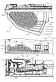
図3に示すように、パチンコ機10の背面側には、制御基板ユニット90,91と、裏パックユニット94とが主に備えられている。制御基板ユニット90は、主基板(主制御装置110)と音声ランプ制御基板(音声ランプ制御装置113)と表示制御基板(表示制御装置114)とが搭載されてユニット化されている。制御基板ユニット91は、払出制御基板(払出制御装置111)と発射制御基板(発射制御装置112)と電源基板(電源装置115)とカードユニット接続基板116とが搭載されてユニット化されている。   As shown in FIG. 3, control board units 90 and 91 and a back pack unit 94 are mainly provided on the back side of the pachinko machine 10. The control board unit 90 is unitized by mounting a main board (main control device 110), a voice lamp control board (voice lamp control device 113), and a display control board (display control device 114). The control board unit 91 is unitized by mounting a payout control board (payout control device 111), a firing control board (firing control device 112), a power supply board (power supply device 115), and a card unit connection board 116.

裏パックユニット94は、保護カバー部を形成する裏パック92と払出ユニット93とがユニット化されている。また、各制御基板には、各制御を司る1チップマイコンとしてのMPU、各種機器との連絡をとるポート、各種抽選の際に用いられる乱数発生器、時間計数や同期を図る場合などに使用されるクロックパルス発生回路等が、必要に応じて搭載されている。   The back pack unit 94 includes a back pack 92 forming a protective cover and a payout unit 93 as a unit. Also, each control board is used for MPU as a one-chip microcomputer that controls each control, a port for communicating with various devices, a random number generator used in various lottery, time counting and synchronization. A clock pulse generating circuit and the like are installed as needed.

なお、主制御装置110、音声ランプ制御装置113及び表示制御装置114、払出制御装置111及び発射制御装置112、電源装置115、カードユニット接続基板116は、それぞれ基板ボックス100〜104に収納されている。基板ボックス100〜104は、ボックスベースと該ボックスベースの開口部を覆うボックスカバーとを備えており、そのボックスベースとボックスカバーとが互いに連結されて、各制御装置や各基板が収納される。   The main control device 110, the voice lamp control device 113 and the display control device 114, the payout control device 111 and the firing control device 112, the power supply device 115, and the card unit connection board 116 are housed in the board boxes 100 to 104, respectively. . The board boxes 100 to 104 each include a box base and a box cover that covers an opening of the box base. The box base and the box cover are connected to each other to house each control device and each board.

また、基板ボックス100(主制御装置110)及び基板ボックス102(払出制御装置111及び発射制御装置112)は、ボックスベースとボックスカバーとを封印ユニット(図示せず)によって開封不能に連結(かしめ構造による連結)している。また、ボックスベースとボックスカバーとの連結部には、ボックスベースとボックスカバーとに亘って封印シール(図示せず)が貼着されている。この封印シールは、脆性な素材で構成されており、基板ボックス100,102を開封するために封印シールを剥がそうとしたり、基板ボックス100,102を無理に開封しようとすると、ボックスベース側とボックスカバー側とに切断される。よって、封印ユニット又は封印シールを確認することで、基板ボックス100,102が開封されたかどうかを知ることができる。   Further, in the board box 100 (main controller 110) and the board box 102 (payout controller 111 and launch controller 112), a box base and a box cover are connected in an unopenable manner by a sealing unit (not shown) (caulking structure). (Consolidated by). Further, a seal (not shown) is attached to the connecting portion between the box base and the box cover so as to extend over the box base and the box cover. The seal sticker is made of a brittle material, and if the seal sticker is peeled off to open the board boxes 100 and 102, or if the board boxes 100 and 102 are forcibly opened, the box base side and the box cover are closed. To be cut to the side. Therefore, by checking the sealing unit or the sealing seal, it is possible to know whether the substrate boxes 100 and 102 have been opened.

払出ユニット93は、裏パックユニット94の最上部に位置して上方に開口したタンク130と、タンク130の下方に連結され下流側に向けて緩やかに傾斜するタンクレール131と、タンクレール131の下流側に縦向きに連結されるケースレール132と、ケースレール132の最下流部に設けられ、払出モータ216(図4参照)の所定の電気的構成により球の払出を行う払出装置133とを備えている。タンク130には、遊技ホールの島設備から供給される球が逐次補給され、払出装置133により必要個数の球の払い出しが適宜行われる。タンクレール131には、当該タンクレール131に振動を付加するためのバイブレータ134が取り付けられている。   The payout unit 93 is located at the uppermost part of the back pack unit 94 and opens upward, the tank rail 131 that is connected to the lower side of the tank 130 and is gently inclined toward the downstream side, and the downstream of the tank rail 131. A case rail 132 that is vertically connected to the side, and a payout device 133 that is provided at the most downstream portion of the case rail 132 and that pays out the balls by a predetermined electrical configuration of the payout motor 216 (see FIG. 4). ing. The tank 130 is sequentially replenished with balls supplied from the island facility of the game hall, and the required number of balls is paid out by the payout device 133 as appropriate. A vibrator 134 for applying vibration to the tank rail 131 is attached to the tank rail 131.

また、払出制御装置111には状態復帰スイッチ120が設けられ、発射制御装置112には可変抵抗器の操作つまみ121が設けられ、電源装置115にはRAM消去スイッチ122が設けられている。状態復帰スイッチ120は、例えば、払出モータ216(図4参照)部の球詰まり等、払出エラーの発生時に球詰まりを解消(正常状態への復帰)するために操作される。操作つまみ121は、発射ソレノイドの発射力を調整するために操作される。RAM消去スイッチ122は、パチンコ機10を初期状態に戻したい場合に電源投入時に操作される。   The payout control device 111 is provided with a state return switch 120, the firing control device 112 is provided with a variable resistor operation knob 121, and the power supply device 115 is provided with a RAM erase switch 122. The state return switch 120 is operated to eliminate the ball clogging (return to a normal state) when a dispensing error occurs, such as a ball clogging of the dispensing motor 216 (see FIG. 4). The operation knob 121 is operated to adjust the firing force of the firing solenoid. The RAM erase switch 122 is operated when the power is turned on when it is desired to return the pachinko machine 10 to the initial state.

次に、図4を参照して、本パチンコ機10の電気的構成について説明する。図4は、パチンコ機10の電気的構成を示すブロック図である。   Next, the electrical configuration of the pachinko machine 10 will be described with reference to FIG. FIG. 4 is a block diagram showing an electrical configuration of the pachinko machine 10.

主制御装置110には、演算装置である1チップマイコンとしてのMPU201が搭載されている。MPU201には、該MPU201により実行される各種の制御プログラムや固定値データを記憶したROM202と、そのROM202内に記憶される制御プログラムの実行に際して各種のデータ等を一時的に記憶するためのメモリであるRAM203と、そのほか、割込回路やタイマ回路、データ送受信回路などの各種回路が内蔵されている。主制御装置110では、MPU201によって、大当たり抽選や第1図柄表示装置37A,37B及び第3図柄表示装置81における表示の設定、第2図柄表示装置における表示結果の抽選といったパチンコ機10の主要な処理を実行する。   The main controller 110 is equipped with an MPU 201 as a one-chip microcomputer which is an arithmetic unit. The MPU 201 includes a ROM 202 that stores various control programs executed by the MPU 201 and fixed value data, and a memory that temporarily stores various data when the control program stored in the ROM 202 is executed. In addition to a certain RAM 203, various circuits such as an interrupt circuit, a timer circuit, and a data transmission / reception circuit are built in. In the main controller 110, the main processing of the pachinko machine 10, such as jackpot lottery, setting of display on the first symbol display devices 37A, 37B and the third symbol display device 81, and lottery of the display result on the second symbol display device, by the MPU 201. To execute.

なお、払出制御装置111や音声ランプ制御装置113などのサブ制御装置に対して動作を指示するために、主制御装置110から該サブ制御装置へ各種のコマンドがデータ送受信回路によって送信されるが、かかるコマンドは、主制御装置110からサブ制御装置へ一方向にのみ送信される。   Note that various commands are transmitted from the main control device 110 to the sub control device by the data transmission / reception circuit in order to instruct the sub control devices such as the payout control device 111 and the voice lamp control device 113 to operate. Such a command is transmitted from the main control device 110 to the sub control device only in one direction.

RAM203は、各種エリア、カウンタ、フラグのほか、MPU201の内部レジスタの内容やMPU201により実行される制御プログラムの戻り先番地などが記憶されるスタックエリアと、各種のフラグおよびカウンタ、I/O等の値が記憶される作業エリア(作業領域)とを有している。なお、RAM203は、パチンコ機10の電源の遮断後においても電源装置115からバックアップ電圧が供給されてデータを保持(バックアップ)できる構成となっており、RAM203に記憶されるデータは、すべてバックアップされる。   The RAM 203 stores various areas, counters, and flags, a stack area in which the contents of internal registers of the MPU 201, the return address of a control program executed by the MPU 201, and the like, various flags, counters, I / O, etc. And a work area (work area) in which values are stored. It should be noted that the RAM 203 has a configuration in which a backup voltage is supplied from the power supply device 115 and data can be retained (backup) even after the power of the pachinko machine 10 is cut off, and all the data stored in the RAM 203 is backed up. ..

停電などの発生により電源が遮断されると、その電源遮断時(停電発生時を含む。以下同様)のスタックポインタや、各レジスタの値がRAM203に記憶される。一方、電源投入時(停電解消による電源投入を含む。以下同様)には、RAM203に記憶される情報に基づいて、パチンコ機10の状態が電源遮断前の状態に復帰される。RAM203への書き込みはメイン処理(図示せず)によって電源遮断時に実行され、RAM203に書き込まれた各値の復帰は電源投入時の立ち上げ処理(図示せず)において実行される。なお、MPU201のNMI端子(ノンマスカブル割込端子)には、停電等の発生による電源遮断時に、停電監視回路252からの停電信号SG1が入力されるように構成されており、その停電信号SG1がMPU201へ入力されると、停電時処理としてのNMI割込処理(図示せず)が即座に実行される。   When the power is cut off due to the occurrence of a power failure or the like, the RAM 203 stores the stack pointer at the time of the power shutdown (including the occurrence of a power failure. The same applies to the following) and the value of each register. On the other hand, at the time of power-on (including power-on by eliminating power failure. The same applies to the following), the state of the pachinko machine 10 is returned to the state before power-off based on the information stored in the RAM 203. Writing to the RAM 203 is executed by a main process (not shown) when the power is cut off, and restoration of each value written in the RAM 203 is executed by a startup process (not shown) when the power is turned on. The NMI terminal (non-maskable interrupt terminal) of the MPU 201 is configured so that the power failure signal SG1 from the power failure monitoring circuit 252 is input when the power is shut off due to a power failure or the like, and the power failure signal SG1 is input to the MPU 201. When input to, an NMI interrupt process (not shown) as a power failure process is immediately executed.

主制御装置110のMPU201には、アドレスバス及びデータバスで構成されるバスライン204を介して入出力ポート205が接続されている。入出力ポート205には、払出制御装置111、音声ランプ制御装置113、第1図柄表示装置37A,37B、第2図柄表示装置、第2図柄保留ランプ、特定入賞口65aの開閉板の下辺を軸として前方側に開閉駆動するための大開放口ソレノイドや電動役物を駆動するためのソレノイドなどからなるソレノイド209が接続され、MPU201は、入出力ポート205を介してこれらに対し各種コマンドや制御信号を送信する。   An input / output port 205 is connected to the MPU 201 of the main controller 110 via a bus line 204 composed of an address bus and a data bus. In the input / output port 205, the payout control device 111, the voice lamp control device 113, the first symbol display devices 37A and 37B, the second symbol display device, the second symbol holding lamp, and the lower side of the opening / closing plate of the specific winning opening 65a are axes. Is connected to a solenoid 209 including a large opening solenoid for driving to open and close to the front side and a solenoid for driving an electric accessory, and the MPU 201 sends various command and control signals to them via an input / output port 205. To send.

また、入出力ポート205には、図示しないスイッチ群およびスライド位置検出センサSや回転位置検出センサRを含むセンサ群などからなる各種スイッチ208、電源装置115に設けられた後述のRAM消去スイッチ回路253が接続され、MPU201は各種スイッチ208から出力される信号や、RAM消去スイッチ回路253より出力されるRAM消去信号SG2に基づいて各種処理を実行する。   Further, the input / output port 205 includes various switches 208 including a switch group (not shown) and a sensor group including the slide position detecting sensor S and the rotational position detecting sensor R, and a RAM erasing switch circuit 253 described later provided in the power supply device 115. Are connected, and the MPU 201 executes various processes based on the signals output from the various switches 208 and the RAM erase signal SG2 output from the RAM erase switch circuit 253.

払出制御装置111は、払出モータ216を駆動させて賞球や貸出球の払出制御を行うものである。演算装置であるMPU211は、そのMPU211により実行される制御プログラムや固定値データ等を記憶したROM212と、ワークメモリ等として使用されるRAM213とを有している。   The payout control device 111 drives the payout motor 216 to perform payout control of prize balls and rental balls. The MPU 211, which is an arithmetic unit, has a ROM 212 that stores a control program executed by the MPU 211, fixed value data, and the like, and a RAM 213 that is used as a work memory and the like.

払出制御装置111のRAM213は、主制御装置110のRAM203と同様に、MPU211の内部レジスタの内容やMPU211により実行される制御プログラムの戻り先番地などが記憶されるスタックエリアと、各種のフラグおよびカウンタ、I/O等の値が記憶される作業エリア(作業領域)とを有している。RAM213は、パチンコ機10の電源の遮断後においても電源装置115からバックアップ電圧が供給されてデータを保持(バックアップ)できる構成となっており、RAM213に記憶されるデータは、すべてバックアップされる。なお、主制御装置110のMPU201と同様、MPU211のNMI端子にも、停電等の発生による電源遮断時に停電監視回路252から停電信号SG1が入力されるように構成されており、その停電信号SG1がMPU211へ入力されると、停電時処理としてのNMI割込処理(図示せず)が即座に実行される。   The RAM 213 of the payout control device 111, like the RAM 203 of the main control device 110, has a stack area in which the contents of the internal register of the MPU 211 and the return address of the control program executed by the MPU 211 are stored, and various flags and counters. , I / O and the like are stored in the work area (work area). The RAM 213 is configured to be able to retain (backup) data by being supplied with a backup voltage from the power supply device 115 even after the power of the pachinko machine 10 is cut off, and all the data stored in the RAM 213 is backed up. Note that, like the MPU 201 of the main controller 110, the NMI terminal of the MPU 211 is also configured to receive the power failure signal SG1 from the power failure monitoring circuit 252 when the power is shut off due to a power failure or the like. When input to the MPU 211, an NMI interrupt process (not shown) as a power failure process is immediately executed.

払出制御装置111のMPU211には、アドレスバス及びデータバスで構成されるバスライン214を介して入出力ポート215が接続されている。入出力ポート215には、主制御装置110や払出モータ216、発射制御装置112などがそれぞれ接続されている。また、図示はしないが、払出制御装置111には、払い出された賞球を検出するための賞球検出スイッチが接続されている。なお、該賞球検出スイッチは、払出制御装置111に接続されるが、主制御装置110には接続されていない。   An input / output port 215 is connected to the MPU 211 of the payout control device 111 via a bus line 214 composed of an address bus and a data bus. The main controller 110, the payout motor 216, the firing controller 112, etc. are connected to the input / output port 215. Although not shown, the payout control device 111 is connected with a prize ball detection switch for detecting the paid prize balls. The prize ball detection switch is connected to the payout control device 111 but not to the main control device 110.

発射制御装置112は、主制御装置110により球の発射の指示がなされた場合に、操作ハンドル51の回動操作量に応じた球の打ち出し強さとなるよう球発射ユニット112aを制御するものである。球発射ユニット112aは、図示しない発射ソレノイドおよび電磁石を備えており、その発射ソレノイドおよび電磁石は、所定条件が整っている場合に駆動が許可される。具体的には、遊技者が操作ハンドル51に触れていることをタッチセンサ51aにより検出し、球の発射を停止させるための発射停止スイッチ51bがオフ(操作されていないこと)を条件に、操作ハンドル51の回動操作量(回動位置)に対応して発射ソレノイドが励磁され、操作ハンドル51の操作量に応じた強さで球が発射される。   The firing control device 112 controls the ball firing unit 112a so that when the main control device 110 gives an instruction to fire a sphere, the sphere launching unit 112a has a launching strength corresponding to the amount of rotation of the operation handle 51. .. The ball firing unit 112a includes a firing solenoid and an electromagnet, which are not shown, and the firing solenoid and the electromagnet are permitted to be driven when a predetermined condition is satisfied. Specifically, the touch sensor 51a detects that the player is touching the operation handle 51, and operates the firing stop switch 51b for stopping the firing of the ball to be off (not operated). The firing solenoid is excited according to the amount of rotation operation (rotational position) of the handle 51, and a ball is emitted with a strength corresponding to the amount of operation of the operation handle 51.

音声ランプ制御装置113は、音声出力装置(図示しないスピーカなど)226における音声の出力、ランプ表示装置(電飾部29〜33、表示ランプ34など)227における点灯および消灯の出力、変動演出(変動表示)や予告演出といった表示制御装置114で行われる第3図柄表示装置81の表示態様の設定などを制御するものである。演算装置であるMPU221は、そのMPU221により実行される制御プログラムや固定値データ等を記憶したROM222と、ワークメモリ等として使用されるRAM223とを有している。   The voice lamp control device 113 outputs a voice in a voice output device (such as a speaker (not shown)) 226, outputs a light and a light in a lamp display device (such as the illumination units 29 to 33 and the display lamp 34) 227, and produces a variation (variation). It is for controlling the setting of the display mode of the third symbol display device 81 performed by the display control device 114 such as display) and notice production. The MPU 221 which is an arithmetic unit has a ROM 222 which stores a control program executed by the MPU 221 and fixed value data and the like, and a RAM 223 which is used as a work memory and the like.

音声ランプ制御装置113のMPU221には、アドレスバス及びデータバスで構成されるバスライン224を介して入出力ポート225が接続されている。入出力ポート225には、主制御装置110、表示制御装置114、音声出力装置226、ランプ表示装置227、その他装置228、枠ボタン22などがそれぞれ接続されている。   An input / output port 225 is connected to the MPU 221 of the audio lamp control device 113 via a bus line 224 composed of an address bus and a data bus. The main control device 110, the display control device 114, the audio output device 226, the lamp display device 227, the other device 228, the frame button 22, etc. are connected to the input / output port 225, respectively.

音声ランプ制御装置113は、主制御装置110から受信した各種のコマンド(変動パターンコマンド、停止種別コマンド等)に基づいて、第3図柄表示装置81の表示態様を決定し、決定した表示態様をコマンド(表示用変動パターンコマンド、表示用停止種別コマンド等)によって表示制御装置114へ通知する。また、音声ランプ制御装置113は、枠ボタン22からの入力を監視し、遊技者によって枠ボタン22が操作された場合は、第3図柄表示装置81で表示されるステージを変更したり、スーパーリーチ時の演出内容を変更したりするように、表示制御装置114へ指示する。ステージが変更される場合は、変更後のステージに応じた背面画像を第3図柄表示装置81に表示させるべく、変更後のステージに関する情報を含めた背面画像変更コマンドを表示制御装置114へ送信する。ここで、背面画像とは、第3図柄表示装置81に表示させる主要な画像である第3図柄の背面側に表示される画像のことである。表示制御装置114は、この音声ランプ制御装置113から送信されるコマンドに従って、第3図柄表示装置81に各種の画像を表示する。   The voice lamp control device 113 determines the display mode of the third symbol display device 81 based on various commands (variation pattern command, stop type command, etc.) received from the main control device 110, and commands the determined display mode. The display control device 114 is notified by (display variation pattern command, display stop type command, etc.). Further, the voice lamp control device 113 monitors the input from the frame button 22, and when the frame button 22 is operated by the player, the stage displayed on the third symbol display device 81 is changed or the super reach is performed. The display control device 114 is instructed to change the content of the effect at that time. When the stage is changed, in order to display the rear image corresponding to the changed stage on the third symbol display device 81, a rear image change command including information about the changed stage is transmitted to the display control device 114. . Here, the back image is an image displayed on the back side of the third symbol which is the main image displayed on the third symbol display device 81. The display control device 114 displays various images on the third symbol display device 81 according to the command transmitted from the voice lamp control device 113.

また、音声ランプ制御装置113は、表示制御装置114から第3図柄表示装置81の表示内容を表すコマンド(表示コマンド)を受信する。音声ランプ制御装置113では、表示制御装置114から受信した表示コマンドに基づき、第3図柄表示装置81の表示内容に合わせて、その表示内容に対応する音声を音声出力装置226から出力し、また、その表示内容に対応させてランプ表示装置227の点灯および消灯を制御する。   Further, the voice lamp control device 113 receives a command (display command) indicating the display content of the third symbol display device 81 from the display control device 114. In the voice lamp control device 113, based on the display command received from the display control device 114, in accordance with the display content of the third symbol display device 81, a voice corresponding to the display content is output from the voice output device 226, and, Lighting and extinguishing of the lamp display device 227 are controlled in accordance with the displayed contents.

表示制御装置114は、音声ランプ制御装置113及び第3図柄表示装置81が接続され、音声ランプ制御装置113より受信したコマンドに基づいて、第3図柄表示装置81における第3図柄の変動演出などの表示を制御するものである。また、表示制御装置114は、第3図柄表示装置81の表示内容を通知する表示コマンドを適宜音声ランプ制御装置113へ送信する。音声ランプ制御装置113は、この表示コマンドによって示される表示内容にあわせて音声出力装置226から音声を出力することで、第3図柄表示装置81の表示と音声出力装置226からの音声出力とをあわせることができる。   The display control device 114 is connected to the voice lamp control device 113 and the third symbol display device 81, and based on a command received from the voice lamp control device 113, such as a variation effect of the third symbol on the third symbol display device 81. It controls the display. Further, the display control device 114 appropriately transmits a display command for notifying the display content of the third symbol display device 81 to the voice lamp control device 113. The voice lamp control device 113 outputs the voice from the voice output device 226 in accordance with the display content indicated by this display command, thereby matching the display of the third symbol display device 81 and the voice output from the voice output device 226. be able to.

電源装置115は、パチンコ機10の各部に電源を供給するための電源部251と、停電等による電源遮断を監視する停電監視回路252と、RAM消去スイッチ122(図3参照)が設けられたRAM消去スイッチ回路253とを有している。電源部251は、図示しない電源経路を通じて、各制御装置110〜114等に対して各々に必要な動作電圧を供給する装置である。その概要としては、電源部251は、外部より供給される交流24ボルトの電圧を取り込み、各種スイッチ208などの各種スイッチや、ソレノイド209などのソレノイド、モータ等を駆動するための12ボルトの電圧、ロジック用の5ボルトの電圧、RAMバックアップ用のバックアップ電圧などを生成し、これら12ボルトの電圧、5ボルトの電圧及びバックアップ電圧を各制御装置110〜114等に対して必要な電圧を供給する。   The power supply device 115 is provided with a power supply unit 251 for supplying power to each unit of the pachinko machine 10, a power failure monitoring circuit 252 for monitoring power interruption due to power failure, etc., and a RAM erase switch 122 (see FIG. 3). And an erase switch circuit 253. The power supply unit 251 is a device that supplies a necessary operating voltage to each of the control devices 110 to 114 and the like through a power supply path (not shown). As its outline, the power supply unit 251 takes in a voltage of 24 V AC supplied from the outside, and 12 V voltage for driving various switches such as various switches 208, solenoids such as the solenoid 209, and motors, A 5 volt voltage for logic, a backup voltage for RAM backup, and the like are generated, and the 12 volt voltage, 5 volt voltage, and backup voltage are supplied to the control devices 110 to 114 and the like as necessary.

停電監視回路252は、停電等の発生による電源遮断時に、主制御装置110のMPU201及び払出制御装置111のMPU211の各NMI端子へ停電信号SG1を出力するための回路である。停電監視回路252は、電源部251から出力される最大電圧である直流安定24ボルトの電圧を監視し、この電圧が22ボルト未満になった場合に停電(電源断、電源遮断)の発生と判断して、停電信号SG1を主制御装置110及び払出制御装置111へ出力する。停電信号SG1の出力によって、主制御装置110及び払出制御装置111は、停電の発生を認識し、NMI割込処理を実行する。なお、電源部251は、直流安定24ボルトの電圧が22ボルト未満になった後においても、NMI割込処理の実行に充分な時間の間、制御系の駆動電圧である5ボルトの電圧の出力を正常値に維持するように構成されている。よって、主制御装置110及び払出制御装置111は、NMI割込処理(図示せず)を正常に実行し完了することができる。   The power failure monitoring circuit 252 is a circuit for outputting a power failure signal SG1 to each NMI terminal of the MPU 201 of the main controller 110 and the MPU 211 of the payout controller 111 when the power is shut off due to the occurrence of a power failure or the like. The power failure monitoring circuit 252 monitors the voltage of DC stable 24V which is the maximum voltage output from the power supply unit 251, and determines that a power failure (power interruption, power interruption) occurs when this voltage becomes less than 22V. Then, the power failure signal SG1 is output to the main controller 110 and the payout controller 111. By the output of the power failure signal SG1, the main controller 110 and the payout controller 111 recognize the occurrence of the power failure and execute the NMI interrupt process. The power supply unit 251 outputs the voltage of 5 V which is the drive voltage of the control system for a sufficient time to execute the NMI interrupt processing even after the voltage of DC stable 24 V becomes less than 22 V. Is maintained at a normal value. Therefore, the main controller 110 and the payout controller 111 can normally execute and complete the NMI interrupt process (not shown).

RAM消去スイッチ回路253は、RAM消去スイッチ122(図3参照)が押下された場合に、主制御装置110へ、バックアップデータをクリアさせるためのRAM消去信号SG2を出力するための回路である。主制御装置110は、パチンコ機10の電源投入時に、RAM消去信号SG2を入力した場合に、バックアップデータをクリアすると共に、払出制御装置111においてバックアップデータをクリアさせるための払出初期化コマンドを払出制御装置111に対して送信する。   The RAM erase switch circuit 253 is a circuit for outputting a RAM erase signal SG2 for clearing the backup data to the main controller 110 when the RAM erase switch 122 (see FIG. 3) is pressed. When the RAM erase signal SG2 is input when the pachinko machine 10 is powered on, the main controller 110 clears the backup data, and the payout controller 111 issues a payout initialization command for clearing the backup data. It is transmitted to the device 111.

次いで、図5から図34を参照して、下皿50について説明する。まず、下皿50の全体構成について、図5から図9を参照して説明する。図5は、内枠12及び下皿50の正面斜視図であり、図6は、内枠12及び下皿50の分解正面斜視図である。   Next, the lower plate 50 will be described with reference to FIGS. 5 to 34. First, the overall configuration of the lower plate 50 will be described with reference to FIGS. 5 to 9. FIG. 5 is a front perspective view of the inner frame 12 and the lower tray 50, and FIG. 6 is an exploded front perspective view of the inner frame 12 and the lower tray 50.

図5及び図6に示すように、内枠12の下方左側には、正面視矩形の開口として形成される払出口23が配設され、その払出口23に対応する位置(即ち、払出口23から払い出された球を受け入れ可能な位置)に下皿50が配設される。上皿17に貯留しきれなかった球は、払出口23から下皿50へ払い出され、下皿50の貯留領域に貯留される。   As shown in FIGS. 5 and 6, on the lower left side of the inner frame 12, a payout opening 23 formed as a rectangular opening in front view is disposed, and a position corresponding to the payout opening 23 (that is, the payout opening 23). The lower plate 50 is arranged at a position where the balls paid out from can be received). The balls that cannot be stored in the upper plate 17 are discharged to the lower plate 50 from the outlet 23 and stored in the storage area of the lower plate 50.

下皿50は、正面視において、貯留領域の左側に払出口23が偏って位置すると共に、底壁部材54が払出口23の下面よりも下方に位置する姿勢で、内枠12に配設される。よって、払出口23から払い出された球は、初期段階では、下皿50の底壁部材54を、正面視左側から右側へ向けて流動しつつ貯留されると共に、底壁部材54全体に球が広がる程度に球が貯留されると、払出口23近傍に山を形成する態様で貯留される。下皿50に所定量の球が貯留されると、遊技者は、球抜きレバー54bを操作して、下皿50の下方に配置された箱(いわゆる千両箱)へ球を排出する。   The lower plate 50 is disposed on the inner frame 12 in a posture in which the outlet 23 is biased to the left side of the storage region and the bottom wall member 54 is positioned below the lower surface of the outlet 23 in a front view. It Therefore, in the initial stage, the balls delivered from the outlet 23 are stored while flowing through the bottom wall member 54 of the lower plate 50 from the left side to the right side in front view, and the balls are distributed to the entire bottom wall member 54. When the balls are stored to such an extent that they spread, the balls are stored in the form of forming a mountain near the outlet 23. When a predetermined amount of balls are stored in the lower plate 50, the player operates the ball removing lever 54b to discharge the balls into a box (so-called 1,000 box) arranged below the lower plate 50.

ここで、本実施形態では、下皿50の側壁部材55が前後に変位可能に形成され、かかる側壁部材55を前方へ張り出させる又は後方へ後退させることで、貯留領域の大きさを拡大または縮小することができる(図7及び図8参照)。よって、貯留領域の大きさが拡大できることで、下皿50からの球抜き操作の頻度を減らすことができ、その分、遊技者が遊技に集中できる状態とすることができる。一方、貯留領域の大きさが縮小できることで、前面枠14の開放時に隣のパチンコ機10に下皿50(張り出された側壁部材55)が干渉することや搬送時の外形が大型化することを抑制できる。かかる下皿50の拡大および縮小の構造について、以下に詳細を説明する。   Here, in the present embodiment, the side wall member 55 of the lower tray 50 is formed so as to be displaceable in the front-rear direction, and the side wall member 55 is projected forward or retracted rearward to enlarge the size of the storage region or It can be reduced (see FIGS. 7 and 8). Therefore, since the size of the storage area can be increased, the frequency of ball removal operations from the lower plate 50 can be reduced, and the player can concentrate on the game accordingly. On the other hand, since the size of the storage area can be reduced, the lower tray 50 (the overhanging side wall member 55) interferes with the adjacent pachinko machine 10 when the front frame 14 is opened, and the outer shape becomes large during transportation. Can be suppressed. The structure for enlarging and reducing the lower plate 50 will be described in detail below.

図7(a)及び図7(b)は、縮小状態における下皿50の正面斜視図であり、図8(a)及び図8(b)は、拡大状態における下皿50の正面斜視図である。また、図9は、下皿50の分解正面斜視図である。なお、図9では、縮小状態における下皿50の分解状態が図示される。   7 (a) and 7 (b) are front perspective views of the lower tray 50 in the contracted state, and FIGS. 8 (a) and 8 (b) are front perspective views of the lower tray 50 in the expanded state. is there. Further, FIG. 9 is an exploded front perspective view of the lower plate 50. Note that FIG. 9 illustrates the disassembled state of the lower plate 50 in the contracted state.

図7から図9に示すように、下皿50は、貯留領域の底面を形成する底壁部材54と、その底壁部材54から立設され貯留領域の側面を形成する側壁部材55及び内壁部材56と、側壁部材55を底壁部材54に回転可能に軸支するための軸支ピン57及び軸支板58とを主に備える。   As shown in FIGS. 7 to 9, the lower plate 50 includes a bottom wall member 54 that forms the bottom surface of the storage area, and side wall members 55 and inner wall members that are erected from the bottom wall member 54 and form the side surfaces of the storage area. 56, and a pivot pin 57 and a pivot plate 58 for pivotally supporting the side wall member 55 on the bottom wall member 54.

底壁部材54は、前方へ向けて略水平に張り出した姿勢で内枠12の前面に配設される板状の部材であり、下皿50の貯留領域から球を排出するための開口である球抜き穴54aと、その球抜き穴54aを開放させる際に遊技者に操作される球抜きレバー54bとを備える。球抜き穴54aは、底壁部材54の上面視において、下皿50の貯留領域の右側(払出口23と反対側)に偏って配設され、底壁部材54の上面は、四方から球抜き穴54aへ向けて下降傾斜する形態に形成される。   The bottom wall member 54 is a plate-shaped member that is disposed on the front surface of the inner frame 12 in a posture that it projects substantially horizontally toward the front, and is an opening for discharging a ball from the storage area of the lower tray 50. The ball-draining hole 54a and the ball-draining lever 54b operated by the player when opening the ball-draining hole 54a are provided. The ball-draining holes 54a are arranged so as to be biased to the right side of the storage area of the lower plate 50 (the side opposite to the outlet 23) in a top view of the bottom wall member 54, and the upper surface of the bottom wall member 54 is ball-drained from four sides. It is formed so as to be inclined downward toward the hole 54a.

側壁部材55は、上面視略L字形状に形成され、その略L字形状の長辺部分(第1片551X〜557X、図11〜図19参照)の一端側および短辺部分(第2片551Y〜557Y、図11〜図19参照)の他端側を前面枠12の正面へ向けることで、L字形状の屈曲部分を前面枠12の前方へ突出させた姿勢に配設される。よって、前面枠12の前面には、側壁部材55によって上面視略三角形状の空間が区画される。側壁部材55は、上面視略L字形状の長辺部分の一端(正面視左側、即ち、前面枠14が開閉可能に軸支される側と同じ側の端部)が、軸支ピン57及び取付板58により底壁部材54に回転可能に軸支される。   The side wall member 55 is formed in a substantially L shape in a top view, and one end side and a short side portion (second piece) of the substantially L-shaped long side portion (first pieces 551X to 557X, see FIGS. 11 to 19). 551Y to 557Y (see FIGS. 11 to 19), the other end side is directed to the front surface of the front frame 12, so that the L-shaped bent portion is disposed in a position in which the front frame 12 is projected forward. Therefore, the side wall member 55 defines a space having a substantially triangular shape in a top view on the front surface of the front frame 12. In the side wall member 55, one end (the left side in front view, that is, the end on the same side as the side on which the front frame 14 is pivotably supported) of the long side portion of the substantially L-shape in a top view has a shaft support pin 57 and The mounting plate 58 rotatably supports the bottom wall member 54.

なお、側壁部材55は、上面視略L字形状の複数(本実施形態では7個)の分割体(第1分割体551から第7分割体557、図11から図19参照)を、回転軸(軸支ピン57)の軸方向に沿って重ね合わせて形成される。これら各分割体551〜557は、軸支ピン57を回転中心として回転されると、上層側の分割体ほど外方へ大きく変位されることで、階段形状を形成し、下皿50の貯留領域を拡大させる。よって、底壁部材54における球抜き穴54a(図9参照)の配置の自由度を確保できる。   The side wall member 55 includes a plurality of (seven in the present embodiment) divided bodies (first divided body 551 to seventh divided body 557, see FIGS. 11 to 19) having a substantially L-shape when viewed from the top of the rotary shaft. It is formed by overlapping along the axial direction of the (shaft support pin 57). When each of the divided bodies 551 to 557 is rotated about the shaft support pin 57, the divided bodies on the upper layer side are displaced to the outer side by a larger amount, thereby forming a staircase shape, and the storage area of the lower plate 50. To expand. Therefore, it is possible to secure the degree of freedom in arranging the ball hole 54a (see FIG. 9) in the bottom wall member 54.

即ち、底壁部および側壁部を遊技者の操作により前後にスライド変位させることで、貯留領域を拡大または縮小する構造では、固定側の底壁部とスライド側の底壁部との重なり部分には球抜き穴を配置することができず、その配置の自由度が低下する。   That is, in the structure in which the bottom wall portion and the side wall portion are slidably displaced back and forth by the player's operation to expand or contract the storage area, the fixed side bottom wall portion and the slide side bottom wall portion overlap each other. Is unable to place a ball hole, and the degree of freedom of its placement is reduced.

これに対し、本実施形態によれば、上下に重ね合わせた各分割体551〜557が変位して階段形状を形成することで貯留領域を拡大する構造であり、貯留領域の拡大または縮小のために変位する部位(各分割体551〜557)と底壁部材54との間に重なり代が形成されない。よって、底壁部材54の任意の位置に球抜き穴54aを配置することができ、その配置の自由度を確保できる。   On the other hand, according to the present embodiment, the divided regions 551 to 557, which are vertically stacked, are displaced to form a staircase shape, thereby expanding the storage region. The overlap margin is not formed between the portion (each divided body 551 to 557) displaced to the bottom wall member 54. Therefore, the ball hole 54a can be arranged at an arbitrary position of the bottom wall member 54, and the degree of freedom of the arrangement can be secured.

また、側壁部材55は、上層側の分割体ほど外方へ大きく変位されることで、階段形状に拡大される(図8参照)。即ち、上層側の分割体ほど遊技者から視て手前側に張り出されるので、上皿17との間の間隔を狭めることなく、かつ、手前側の開口が広くされた状態で、貯留領域を拡大するので、遊技者の手を下皿50内へ入れやすくすることができる。言い換えれば、その分、上皿17を大型化することができる。また、このように、側壁部材55が遊技者から視て手前側に張り出されることで、下皿50が拡大状態にあることを遊技者に認識させやすくすることができる。   Further, the side wall member 55 is expanded in the outward direction as the divided body on the upper layer side is largely displaced, so that the side wall member 55 is expanded in a step shape (see FIG. 8). That is, since the upper layer side divided body is projected to the front side when viewed from the player, the storage area is expanded without narrowing the space between the upper plate 17 and the front side opening. Since it is enlarged, the player's hand can be easily put in the lower plate 50. In other words, the upper plate 17 can be upsized accordingly. Further, as described above, the side wall member 55 is projected to the front side when viewed from the player, so that the player can easily recognize that the lower plate 50 is in the enlarged state.

内壁部材56は、底壁部材54から立設される板状の部材であり、側壁部材55の上面視略L字形状の短辺部分(第2片551Y〜557Y)の内側(貯留領域側)に配設され、下皿50の貯留領域における側面の一部を形成する。即ち、下皿50の貯留領域における側面は、縮小状態では、内枠12と、側壁部材55の上面視略L字形状の長辺部分(第1片551X〜557X)と、内壁部材56とにより形成され、拡大状態では、側壁部材55の上面視略L字形状の短辺部分(第2片551Y〜557Y)がこれに加わる。   The inner wall member 56 is a plate-shaped member that is erected from the bottom wall member 54, and is inside (the storage region side) of the short side portion (second pieces 551Y to 557Y) of the side wall member 55 that is substantially L-shaped in a top view. And forms a part of the side surface of the storage area of the lower plate 50. That is, the side surface of the storage area of the lower plate 50 is formed by the inner frame 12, the long side portion (first piece 551X to 557X) of the side wall member 55 having a substantially L shape in a top view, and the inner wall member 56 in the contracted state. In the formed and enlarged state, the short side portions (second pieces 551Y to 557Y) of the side wall member 55 which are substantially L-shaped in a top view are added thereto.

ここで、側壁部材55の上面視略L字形状の短辺部分(第2片551Y〜557Y)は、それぞれ長さ寸法が異なる。そのため、縮小状態では、それぞれの端部が互いに異なる位置に配設され、短辺部分(第2片551Y〜557Y)の長手方向に沿って複数の段差が形成される。よって、かかる短辺部分(第2片551Y〜557Y)により下皿50の貯留領域における側面が形成されると、例えば、遊技を終了する際に下皿50に残った1乃至数個の球を取り出す際に、球が段差に引っ掛かり、取り出し難い。   Here, the short side portions (second pieces 551Y to 557Y) of the side wall member 55 which are substantially L-shaped in a top view have different length dimensions. Therefore, in the contracted state, the respective end portions are arranged at positions different from each other, and a plurality of steps are formed along the longitudinal direction of the short side portions (second pieces 551Y to 557Y). Therefore, when the side surface in the storage area of the lower plate 50 is formed by the short side portions (second pieces 551Y to 557Y), for example, one to several balls remaining in the lower plate 50 when the game is finished are removed. When taking it out, the ball gets caught in the step and it is difficult to take out.

即ち、下皿50の上方には上皿17が配設され、スペースが狭いため、下皿50内の球を指で摘み上げることは困難である。そのため、左手の指で球を下皿50の貯留領域における向かって右側(ハンドル51側)の側面に押し付けつつ手前側に転がして取り出すこととなる。この場合に、上述した段差が形成されていると、球が段差に引っ掛かり、取り出し難くなる。   That is, since the upper plate 17 is arranged above the lower plate 50 and the space is small, it is difficult to pick up the ball in the lower plate 50 with a finger. For this reason, the ball of the left hand is pressed against the side surface of the lower plate 50 on the right side (handle 51 side) in the storage area, and is rolled out and taken out. In this case, if the above-mentioned step is formed, the sphere will be caught in the step and it will be difficult to take it out.

これに対し、本実施形態では、皿50の貯留領域における向かって右側(ハンドル51側)の側面は、縮小状態では、内壁部材56により形成され、平坦面状に形成される。即ち、短辺部分(第2片551Y〜557Y)による段差を、内壁部材56により隠すことができる。その結果、左手の指で球を下皿50の貯留領域における向かって右側(ハンドル51側)の側面に押し付けつつ手前側に転がすことで、容易に取り出すことができる。   On the other hand, in the present embodiment, the side surface on the right side (handle 51 side) in the storage area of the dish 50 is formed by the inner wall member 56 in the contracted state, and is formed into a flat surface shape. That is, the step due to the short side portion (second pieces 551Y to 557Y) can be hidden by the inner wall member 56. As a result, the ball can be easily taken out by rolling it toward the front side while pressing the ball against the side surface on the right side (handle 51 side) of the storage area of the lower plate 50 with the finger of the left hand.

このように、本実施形態では、内壁部材56が貯留領域の内壁の一部を形成し、図7に示す縮小状態では、各分割体551〜557の略L字形状の短辺部分(第2片551Y〜557Y)を内壁部材56の背面側に配置し、図8に示す拡大状態では、各分割体551〜557の略L字形状の短辺部分(第2片551Y〜557Y)を内壁部材56の側方に並設させ、かかる略L字形状の短辺部分(第2片551Y〜557Y)と内壁部材56との両者により貯留領域の内壁の一部を形成する。これにより、略L字形状の短辺部分の長さ寸法を短縮化して、その分、略L字形状の短辺部分の移動のために必要なスペースを抑制することができる。   As described above, in the present embodiment, the inner wall member 56 forms a part of the inner wall of the storage region, and in the reduced state shown in FIG. 7, the substantially L-shaped short side portion (second portion) of each of the divided bodies 551 to 557 is (The pieces 551Y to 557Y) are arranged on the back side of the inner wall member 56, and in the enlarged state shown in FIG. 8, the substantially L-shaped short side portions (second pieces 551Y to 557Y) of the respective divided bodies 551 to 557 are used as the inner wall member. A part of the inner wall of the storage region is formed by both of the substantially L-shaped short side portions (second pieces 551Y to 557Y) and the inner wall member 56 arranged side by side. As a result, the length dimension of the substantially L-shaped short side portion can be shortened, and the space required for the movement of the substantially L-shaped short side portion can be suppressed accordingly.

即ち、内壁部材56を設けない場合には、貯留領域が縮小された状態においてのみでなく、貯留領域が拡大された状態においても、各分割体551〜557の略L字形状の短辺部分(第2片551Y〜557Y)が貯留領域の内壁の一部となる必要があるため、略L字形状の短辺部分の長さ寸法として、内壁部材56に相当する長さ寸法と貯留領域(内壁)の拡大分に相当する長さ寸法とを加算した寸法が必要となる。   That is, when the inner wall member 56 is not provided, not only in the state where the storage area is reduced but also in the state where the storage area is enlarged, the short side portions of the substantially L-shaped portions of the divided bodies 551 to 557 ( Since the second pieces 551Y to 557Y) need to be a part of the inner wall of the storage area, the length dimension of the short side portion of the substantially L shape is equivalent to the length of the inner wall member 56 and the storage area (inner wall). ) And the length dimension corresponding to the expanded amount are added.

そのため、略L字形状の短辺部分(第2片551Y〜557Y)の移動のために必要なスペースが大きくなり、かかるスペースの一部を、内枠12の内部空間に確保する必要がある。即ち、略L字形状の短辺部分(第2片551Y〜557Y)の他端側を、図7に示す縮小状態において、内枠12の内部空間に収容させる必要が生じる。   Therefore, the space required for the movement of the substantially L-shaped short side portions (second pieces 551Y to 557Y) becomes large, and it is necessary to secure a part of the space in the internal space of the inner frame 12. That is, the other end side of the substantially L-shaped short side portions (second pieces 551Y to 557Y) needs to be housed in the internal space of the inner frame 12 in the contracted state shown in FIG. 7.

これに対し、内壁部材56を設けることで、拡大状態においてのみ、略L字形状の短辺部分(第2片551Y〜557Y)が貯留領域の内壁となれば良いので、略L字形状の短辺部分の長さ寸法を、拡大分に相当する長さ寸法に抑制することができる(内壁部材56に相当する長さ寸法を不要とできる)。その結果、略L字形状の短辺部分の移動のために必要なスペースを抑制でき、そのスペースの一部を内枠12の内部空間に確保することを不要とできる。   On the other hand, by providing the inner wall member 56, the substantially L-shaped short side portions (the second pieces 551Y to 557Y) may serve as the inner wall of the storage region only in the expanded state, and thus the substantially L-shaped short side. The length of the side portion can be suppressed to the length corresponding to the enlarged portion (the length corresponding to the inner wall member 56 can be eliminated). As a result, it is possible to suppress the space required for the movement of the substantially L-shaped short side portion, and it becomes unnecessary to secure a part of the space in the inner space of the inner frame 12.

内壁部材56の背面側には、規制部56aが突設され、その規制部56aは、側壁部材55の上面視略L字形状の短辺部分(第2片551Y)の上面に重なる。よって、球の重量を受けた側壁部材55が下方へ倒れ込もうとすると、規制部56aが側壁部材55(短辺部分)の上面を押圧して、その浮き上がりを抑制できるので、側壁部材55の下方への倒れ込みを抑制することができる。また、規制部56aは、側壁部材55のストッパ部551S1に当接可能とされるので、側壁部材55の拡大方向への回転を規制して張出位置(図9参照)に保持することができる。   A restricting portion 56a is provided on the back side of the inner wall member 56, and the restricting portion 56a overlaps the upper surface of the short side portion (second piece 551Y) of the side wall member 55 which is substantially L-shaped in a top view. Therefore, when the side wall member 55 that receives the weight of the sphere tries to fall down, the restricting portion 56a presses the upper surface of the side wall member 55 (short side portion), and the rising of the side wall member 55 can be suppressed. It is possible to suppress falling down. Further, since the restricting portion 56a can be brought into contact with the stopper portion 551S1 of the side wall member 55, it is possible to restrict the rotation of the side wall member 55 in the expanding direction and hold the side wall member 55 at the projecting position (see FIG. 9). ..

この場合、各分割体551〜557は、上側の分割体ほど略L字形状の短辺部分(第2片551Y〜557Y)の長さ寸法が大きくされ(図11から図19参照)、図8に示す拡大状態が形成されると、上側の分割体ほど外方へ張り出されると共に、略L字形状の短辺部分の端面(拡大方向と反対側、図8右側)がそれぞれ面一に配置されるので(図8参照)、各分割体551〜557の略L字形状の短辺部分どうしの重なり代を確保して、球の重量に対する撓みを抑制しつつ、略L字形状の短辺部分の長さを抑制して、部品コストの抑制を図ることができる。   In this case, in each of the divided bodies 551 to 557, the length dimension of the substantially L-shaped short side portion (second pieces 551Y to 557Y) is made larger toward the upper divided body (see FIGS. 11 to 19), and FIG. When the enlarged state shown in FIG. 3 is formed, the upper divided body is projected outward and the end faces of the substantially L-shaped short side portions (opposite the enlargement direction, the right side in FIG. 8) are arranged flush with each other. (See FIG. 8), the margin for overlapping the substantially L-shaped short sides of each of the divided bodies 551 to 557 is ensured to suppress the deflection of the sphere with respect to the weight of the sphere, and the substantially L-shaped short sides. By suppressing the length of the part, it is possible to suppress the cost of parts.

即ち、図8に示す拡大状態では、各分割体551〜557において、上側の分割体よりも下側の分割体における略L字形状の短辺部分(第2片551Y〜557Y)の端面が突出されていたとしても、その突出分は、隣接する短辺部分に対して撓みの抑制には寄与できない。一方、図7に示す縮小状態では、各分割体551〜557の略L字形状の短辺部分どうしの重なり代が減少されるが、球の重量は内壁部材56に作用され、略L字形状の短辺部分には直接的には作用されない。よって、本構成が有効となる。   That is, in the enlarged state shown in FIG. 8, in each of the divided bodies 551 to 557, the end faces of the substantially L-shaped short side portions (second pieces 551Y to 557Y) of the divided body on the lower side than the upper divided body protrude. Even if it is formed, the protruding portion cannot contribute to the suppression of bending of the adjacent short side portions. On the other hand, in the contracted state shown in FIG. 7, the overlap margin of the short side portions of the substantially L-shaped of each of the divided bodies 551 to 557 is reduced, but the weight of the sphere is acted on the inner wall member 56 and the substantially L-shaped. Is not directly acted on the short side part of. Therefore, this configuration is effective.

また、内壁部材56の規制部56は、図8に示す拡大状態において、それぞれ面一に配置された略L字形状の短辺部分(第2片551Y〜557Y)の端面側の端部における上面に重なる。即ち、後述するように、貯留領域は、縮小状態、第1状態から第5状態および拡大状態の7段階で拡大または縮小されるところ(図22及び図23参照)、そのいずれの状態においても、全ての分割体(第1〜第7分割体551〜557)の略L字形状の短辺部分(第2片551Y〜557Y)と上面視において重なることができる位置に配置される。よって、貯留領域の拡大の程度(7段階のうちのいずれの段階であるか)に関わらず、各分割体551〜557の略L字形状の短辺部分を最適な支点位置で支えることができ、側壁部材55の撓みを抑制できる。   Further, the restricting portion 56 of the inner wall member 56 is, in the enlarged state shown in FIG. 8, an upper surface at the end portion on the end surface side of the substantially L-shaped short side portions (second pieces 551Y to 557Y) arranged flush with each other. Overlap with. That is, as will be described later, the storage area is enlarged or reduced in seven stages of the reduced state, the first state to the fifth state, and the enlarged state (see FIGS. 22 and 23), and in any of the states, All the divided bodies (first to seventh divided bodies 551 to 557) are arranged at positions where they can overlap the substantially L-shaped short side portions (second pieces 551Y to 557Y) in a top view. Therefore, regardless of the degree of expansion of the storage region (which of the seven stages), the short sides of the substantially L-shaped portions of each of the divided bodies 551 to 557 can be supported at the optimum fulcrum position. The bending of the side wall member 55 can be suppressed.

更に、内壁部材56の規制部56は、側壁部材55(第1分割体551)のストッパ部551S1に当接可能となることで、側壁部材55の拡大方向への回転を規制することができる。即ち、規制部56aは、側壁部材55(第1分割体551)の略L字形状の短辺部分(第2片551Y)の上面を支持して撓みを抑制する役割だけでなく、各分割体551〜557の拡大方向への回転を規制するストッパとしての役割も兼用するので、その分、部品点数を削減して、製品コストの低減を図ることができる。   Further, the restriction portion 56 of the inner wall member 56 can contact the stopper portion 551S1 of the side wall member 55 (first divided body 551), so that the rotation of the side wall member 55 in the expansion direction can be restricted. That is, the restricting portion 56a not only plays a role of supporting the upper surface of the substantially L-shaped short side portion (second piece 551Y) of the side wall member 55 (first divided body 551) and suppressing the bending, but also each divided body. Since it also serves as a stopper that restricts the rotation of 551 to 557 in the expanding direction, the number of parts can be reduced and the product cost can be reduced accordingly.

ここで、下皿50がその貯留領域を拡大または縮小可能に形成される場合には、複数のパチンコ機10が並設されたホールにおいて、下皿50が拡大された状態のままで前面枠14が不用意に開放されると、拡大された下皿50が隣のパチンコ機10に接触して破損するおそれがある。   Here, when the lower plate 50 is formed so that its storage area can be expanded or contracted, the front plate 14 is left in an expanded state in the hole where a plurality of pachinko machines 10 are arranged in parallel. If it is opened carelessly, the enlarged lower plate 50 may come into contact with the adjacent pachinko machine 10 and be damaged.

これに対し、本実施形態では、下皿50の回転軸(軸支ピン57)が、前面枠14を開閉可能に軸支する軸(図示せず)と平行であって、幅方向において同じ側(正面視左側)に配設されるので、下皿50が拡大されたまま前面枠14が開放され、隣に設置されたパチンコ機10に下皿50が接触したとしても、側壁部材55を縮小方向に回転させることができるので、下皿50が破損することを抑制することができる。   On the other hand, in the present embodiment, the rotation shaft (the shaft support pin 57) of the lower plate 50 is parallel to the shaft (not shown) that supports the front frame 14 so as to be openable and closable, and the same side in the width direction. Since it is disposed on the left side in the front view, the front plate 14 is opened while the lower plate 50 is enlarged, and the side wall member 55 is reduced even if the lower plate 50 comes into contact with the pachinko machine 10 installed next to it. Since it can be rotated in the direction, it is possible to prevent the lower plate 50 from being damaged.

特に、本実施形態では、側壁部材55が上面視略L字形状に形成され、側壁部材55が内枠12の前面から突出する突出量は、回転軸(軸支ピン57)から離間するに従って大きくされ、上面視略L字形状の屈曲部分で最大とされるので、拡大された下皿50が前面枠14の開放により隣のパチンコ機10に接触した際には、その接触により側壁部材55に作用される押圧力を、側壁部材55を回転軸まわりに回転させるトルクを形成しやすい向きで側壁部材55(長辺部分)に作用させることができる。よって、側壁部材55を縮小方向に回転させやすくして、下皿50が破損することを抑制することができる。   In particular, in this embodiment, the side wall member 55 is formed in a substantially L shape in a top view, and the amount of protrusion of the side wall member 55 from the front surface of the inner frame 12 increases as the distance from the rotation shaft (the shaft support pin 57) increases. When the enlarged lower plate 50 comes into contact with the adjacent pachinko machine 10 due to the opening of the front frame 14, the side wall member 55 is contacted by the contact. The applied pressing force can be applied to the side wall member 55 (long side portion) in such a direction as to easily generate the torque for rotating the side wall member 55 around the rotation axis. Therefore, it is possible to easily rotate the side wall member 55 in the contracting direction and prevent the lower tray 50 from being damaged.

更に、側壁部材55は、上面視略L字形状の長辺部分(第1片551X〜557X)が外方へ凸の円弧状に湾曲して形成されるので、拡大された下皿50が前面枠14の開放により隣のパチンコ機10に接触した際には、側壁部材55(長辺部分の外周面)に沿って相手部材を摺動させ、両者が引っ掛かることを抑制できる。よって、側壁部材55を縮小方向にスムーズに回転させることができ、その結果、下皿50が破損することを抑制することができる。   Further, the side wall member 55 is formed such that the long side portion (first pieces 551X to 557X) of the substantially L-shape in a top view is curved outward in a circular arc shape so that the enlarged lower plate 50 is in front. When the adjacent pachinko machine 10 comes into contact due to the opening of the frame 14, the mating member can be slid along the side wall member 55 (the outer peripheral surface of the long side portion) to prevent the both members from being caught. Therefore, the side wall member 55 can be smoothly rotated in the contraction direction, and as a result, the lower tray 50 can be prevented from being damaged.

また、側壁部材55は、上面視略L字形状の短辺部分(第1片551Y〜557Y)が、後述するように、回転軸(軸支ピン57)を中心とする円弧状に湾曲して形成されるので、拡大された下皿50が前面枠14の開放により隣のパチンコ機10に接触した際には、側壁部材55の短辺部分が相手部材に接触することを抑制できる。即ち、相手部材が側壁部材55の短辺部分に接触して、側壁部材55の縮小方向への回転が阻害されることを抑制できる。その結果、下皿50が破損することを抑制することができる。   Further, in the side wall member 55, a short side portion (first pieces 551Y to 557Y) having a substantially L shape in a top view is curved in an arc shape with a rotation shaft (the shaft support pin 57) as a center, as described later. Since it is formed, when the enlarged lower plate 50 comes into contact with the adjacent pachinko machine 10 due to the opening of the front frame 14, it is possible to prevent the short side portion of the side wall member 55 from coming into contact with the mating member. That is, it is possible to prevent the mating member from contacting the short side portion of the side wall member 55 and inhibiting the rotation of the side wall member 55 in the contraction direction. As a result, it is possible to prevent the lower plate 50 from being damaged.

なお、本実施形態では、下皿50(第1分割体551)がハンドル51と同じ高さ位置に配設される。よって、回転軸(軸支ピン57)と隣接するパチンコ機10のハンドル51との間の間隔(水平方向の距離)が、第1分割体551の第1片551Yの水平方向寸法よりも小さい場合には、下皿50が拡大された状態のままで前面枠14が開放されると、拡大された下皿50が隣のパチンコ機10のハンドル51に接触される。   In the present embodiment, the lower plate 50 (first divided body 551) is arranged at the same height position as the handle 51. Therefore, when the interval (horizontal direction distance) between the rotary shaft (axial support pin 57) and the adjacent handle 51 of the pachinko machine 10 is smaller than the horizontal dimension of the first piece 551Y of the first split body 551. When the front frame 14 is opened while the lower plate 50 is in the enlarged state, the enlarged lower plate 50 is brought into contact with the handle 51 of the adjacent pachinko machine 10.

この場合、ハンドル51は、球状に形成されるため、拡大された下皿50が前面枠14の開放により隣のパチンコ機10のハンドル51に接触した際には、側壁部材55(第1片551Yの外周面)に沿って摺動させ、両者が引っ掛かることを抑制できる。よって、側壁部材55を縮小方向にスムーズに回転させることができ、その結果、下皿50が破損することを抑制することができる。   In this case, since the handle 51 is formed in a spherical shape, when the enlarged lower plate 50 comes into contact with the handle 51 of the adjacent pachinko machine 10 due to the opening of the front frame 14, the side wall member 55 (first piece 551Y). It is possible to prevent both from being caught by sliding along the outer peripheral surface). Therefore, the side wall member 55 can be smoothly rotated in the contraction direction, and as a result, the lower tray 50 can be prevented from being damaged.

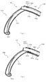
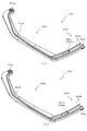
次いで、下皿50の詳細構成について、図10から図34を参照して説明する。図10(a)は、縮小された状態における側壁部材55の上面図であり、図10(b)は、拡大された状態における側壁部材55の上面図である。図11から図13は、図10(a)の矢印A方向視における側壁部材55の分解正面斜視図であり、図14から図16は、図10(a)の矢印B方向視における側壁部材55の分解正面斜視図である。また、図17から図19は、側壁部材55の下面視における分解下面斜視図である。   Next, the detailed configuration of the lower plate 50 will be described with reference to FIGS. 10 to 34. FIG. 10A is a top view of the side wall member 55 in a reduced state, and FIG. 10B is a top view of the side wall member 55 in an enlarged state. 11 to 13 are exploded front perspective views of the side wall member 55 as viewed in the direction of arrow A of FIG. 10A, and FIGS. 14 to 16 are side wall members 55 as viewed in the direction of arrow B of FIG. 10A. FIG. 3 is an exploded front perspective view of FIG. 17 to 19 are exploded bottom perspective views of the side wall member 55 in bottom view.

なお、図11、図14及び図17の(a)及び(b)には第1分割体551及び第2分割体552が、図12、図15及び図18の(a)及び(b)には第3分割体553及び第4分割体554が、図13、図16及び図19の(a)、(b)及び(c)には第5分割体555、第6分割体556及び第7分割体557が、それぞれ図示される。   Note that the first divided body 551 and the second divided body 552 are shown in FIGS. 11, 14 and 17 (a) and (b), and are shown in FIGS. 12, 15 and 18 (a) and (b). The third divided body 553 and the fourth divided body 554 are the fifth divided body 555, the sixth divided body 556, and the seventh divided body 555 in FIGS. 13, 16 and 19 (a), (b) and (c). Dividers 557 are each shown.

図10に示すように、側壁部材55は、上面視略L字形状に形成され、回転軸(軸支ピン57、図9参照)の軸方向に沿って重ね合わされた複数(本実施形態では7個)の分割体(第1分割体551から第7分割体557)から形成される。各分割体551〜557は、上面視において重なる形状(略同一の形状)に樹脂材料から形成される。   As shown in FIG. 10, the side wall member 55 is formed in a substantially L shape in a top view, and a plurality of (7 in the present embodiment, 7 are stacked on each other along the axial direction of the rotation shaft (the shaft support pin 57, see FIG. 9). Individual divided bodies (first divided body 551 to seventh divided body 557). Each of the divided bodies 551 to 557 is formed of a resin material so as to have an overlapping shape (substantially the same shape) in a top view.

具体的には、側壁部材55は、第1分割体551により最上層が形成され、第1分割体551の下面(図10(a)紙面奥側の面)に第2分割体552から第6分割体556がそれぞれ順に配設され、第6分割体556の下面に配設された第7分割体557により最下層が形成される。なお、最下層の第7分割体557は、側壁部材55(図9参照)に締結固定される。   Specifically, the uppermost layer of the side wall member 55 is formed by the first divided body 551, and the second divided body 552 through the sixth divided body 552 are formed on the lower surface of the first divided body 551 (the surface on the back side of the paper in FIG. 10A). The divided bodies 556 are sequentially arranged, and the seventh divided body 557 arranged on the lower surface of the sixth divided body 556 forms the lowermost layer. The seventh divided body 557 of the lowermost layer is fastened and fixed to the side wall member 55 (see FIG. 9).

図11から図19に示すように、第1分割体551から第7分割体557は、一端側に軸支孔551a〜557aが穿設され上面視略L字形状の長辺部分を形成する第1片551X〜557Xと、その第1片551X〜557Xの他端側に連設され上面視略L字形状の短辺部分を形成する第2片551Y〜557Yとから形成される。   As shown in FIGS. 11 to 19, in the first divided body 551 to the seventh divided body 557, shaft support holes 551a to 557a are formed at one end side to form a long side portion having a substantially L shape in a top view. It is formed from one piece 551X to 557X and second pieces 551Y to 557Y that are connected to the other end side of the first piece 551X to 557X and that form a short side portion that is substantially L-shaped in a top view.

第1片551X〜557Xは、貯留領域となる側が凹(即ち、外方へ凸)となる円弧状に、第2片551Y〜557Yは、軸支孔551a〜557aを中心とし且つ略同径の円弧状に、それぞれ上面視形状(軸支孔551a〜557aの軸方向視形状)が湾曲して形成される。   The first pieces 551X to 557X have an arc shape in which the side to be the storage area is concave (that is, outwardly convex), and the second pieces 551Y to 557Y are centered on the shaft support holes 551a to 557a and have substantially the same diameter. The top view shape (the shape of the shaft support holes 551a to 557a as viewed in the axial direction) is curved and formed in an arc shape.

第1片551X〜557Xが外方へ凸となる円弧状に湾曲されることで、貯留領域の大きさを確保できるだけでなく、上述したように、下皿50が拡大されたまま前面枠14が開放され隣のパチンコ機10等に衝突した際に、下皿50(側壁部材55)を閉じやすくできる。また、第2片551Y〜557Yが軸支孔551a〜557aを中心とする円弧状に湾曲されることで、側壁部材55の拡大および縮小の各状態において、周方向に重なり合う状態を維持可能とし、後述するように、側壁部材55の剛性を高め、球の重量によって撓むことを抑制できる。   Since the first pieces 551X to 557X are curved in an arc shape that is convex outward, not only can the size of the storage region be secured, but as described above, the front plate 14 can be maintained while the lower plate 50 is enlarged. The lower tray 50 (side wall member 55) can be easily closed when it is opened and collides with the adjacent pachinko machine 10 or the like. Further, since the second pieces 551Y to 557Y are curved in an arc shape centered on the shaft support holes 551a to 557a, it is possible to maintain the circumferentially overlapping state in each state of expansion and contraction of the side wall member 55, As will be described later, it is possible to increase the rigidity of the side wall member 55 and prevent the side wall member 55 from bending due to the weight of the sphere.

第2分割体552から第7分割体557の第1片552X〜557Xの上面には、第1片552X〜557Xの長手方向に沿って延設され断面矩形状の突起として突設される突起部552b〜557bが配設される(図11から図16参照)。一方、第1分割体551から第6分割体556の第1片551X〜556Xの下面には、第1片551X〜556Xの長手方向に沿って延設され断面凹状の凹溝として凹設される規制溝551c〜556cが配設される(図17から図19参照)。   Protrusions that extend along the longitudinal direction of the first pieces 552X to 557X on the upper surfaces of the first pieces 552X to 557X of the second divided body 552 to the seventh divided body 557 and project as projecting portions having a rectangular cross section. 552b to 557b are provided (see FIGS. 11 to 16). On the other hand, on the lower surface of the first pieces 551X to 556X of the first divided body 551 to the sixth divided body 556, the first pieces 551X to 556X are provided along the longitudinal direction and are formed as concave grooves having a concave cross section. Restriction grooves 551c to 556c are provided (see FIGS. 17 to 19).

各分割体551〜557が上下に重ね合わされると、第2分割体552から第7分割体557の突起部552b〜557bが、第1分割体551から第6分割体556の規制溝551c〜556c内に配設(収納)され、各分割体551〜556が軸支ピン57を中心として回転される際には、突起部552b〜557bが規制溝551c〜556cの内壁面に当接されることで、各分割体551〜557の可動(回転)範囲が規定される(図20参照)。   When the respective divided bodies 551 to 557 are vertically stacked, the protrusions 552b to 557b of the second divided body 552 to the seventh divided body 557 and the restriction grooves 551c to 556c of the first divided body 551 to the sixth divided body 556. When the divided bodies 551 to 556 are arranged (stored) inside and are rotated around the pivot pin 57, the protrusions 552b to 557b are brought into contact with the inner wall surfaces of the restriction grooves 551c to 556c. Then, the movable (rotation) range of each of the divided bodies 551 to 557 is defined (see FIG. 20).

突起部552b〜557bは、貯留領域となる側が凹(即ち、外方へ凸)となる円弧状に上面視形状(軸支孔552a〜557aの軸方向視形状)が湾曲して形成され、軸支孔552a〜557aから第2片552Y〜557Yへ向かうに従って貯留領域と反対側(外方側)に位置する姿勢で配設される。即ち、突起部552b〜557bは、第1片552X〜557Xの長手方向に対して傾斜して延設される。   The projecting portions 552b to 557b are formed by curving the top view shape (the axial view shape of the shaft support holes 552a to 557a) in an arc shape in which the side to be the storage area is concave (that is, outwardly convex). It is arranged such that it is located on the opposite side (outside) from the storage region as it goes from the support holes 552a to 557a toward the second pieces 552Y to 557Y. That is, the protrusions 552b to 557b are provided so as to be inclined with respect to the longitudinal direction of the first pieces 552X to 557X.

規制溝551c〜556cの互いに対向する一対の内壁面は、その下面視形状が、突起部552b〜557bの上面視形状と略同一の円弧状に湾曲して形成され、一方の内壁面は、貯留領域側における第1片552X〜557Xの縁部に沿って配設されると共に、他方の内壁面は、軸支孔551a〜556aから第2片551Y〜556Yへ向かうに従って貯留領域と反対側(外方側)に位置する姿勢で配設される。即ち、規制溝551c〜556cの溝幅は、軸支孔551a〜556aから第2片551Y〜556Yへ向かうに従って漸次拡大される。   The pair of inner wall surfaces of the restriction grooves 551c to 556c facing each other are formed such that the shape in a bottom view thereof is curved in an arc shape substantially the same as the shape in a top view of the protrusions 552b to 557b, and one inner wall surface is reserved. The inner wall surface is arranged along the edges of the first pieces 552X to 557X on the area side, and the other inner wall surface is opposite to the storage area (outer side) from the shaft support holes 551a to 556a toward the second pieces 551Y to 556Y. It is arranged in a posture of being located on the side). That is, the groove widths of the restriction grooves 551c to 556c gradually increase from the shaft support holes 551a to 556a toward the second pieces 551Y to 556Y.

第2分割体552から第5分割体557の第2片552Y〜555Yは、第1片552X〜555Xに平行に連なる第1水平部552e〜555eと、その第1水平部552eの外縁部(軸支孔552a〜555aからの距離が遠い側の縁部)から軸支孔552a〜555aの軸方向に沿って立設される立設部552f〜555fと、その立設部552f〜555fの立設先端から外方(軸支孔552a〜555aから離間する方向)へ向けて第1片552X〜555Xと平行に延設される第2水平部552g〜555gとを備えて形成される。   The second pieces 552Y to 555Y of the second divided body 552 to the fifth divided body 557 include first horizontal portions 552e to 555e that are continuous in parallel with the first pieces 552X to 555X, and an outer edge portion (axis of the shaft) of the first horizontal portion 552e. Standing portions 552f to 555f, which are erected along the axial direction of the shaft supporting holes 552a to 555a from the edges on the side farther from the supporting holes 552a to 555a, and the standing portions of the standing portions 552f to 555f. It is provided with second horizontal portions 552g to 555g extending parallel to the first pieces 552X to 555X from the tip end toward the outside (the direction away from the shaft support holes 552a to 555a).

第6分割体556及び第7分割体557の第2片556Y,557Yは、第1片556Y,557Yに平行に連なる第1水平部556e,557eと、その第1水平部556e,557eの外縁部(軸支孔556aからの距離が遠い側の縁部)から軸支孔556a,557aの軸方向に沿って立設される立設部556f,557fと備えて形成される。即ち、第6分割体556及び第7分割体557では、第2水平部が省略される。なお、第7分割体557の立設部557fには、後述するロック機構77のロック片773(図32及び図33参照)が係合される側面と反対側の側面に傾斜面557f1が形成される。   The second pieces 556Y and 557Y of the sixth divided body 556 and the seventh divided body 557 are first horizontal portions 556e and 557e that extend in parallel to the first pieces 556Y and 557Y, and outer edge portions of the first horizontal portions 556e and 557e. It is provided with standing portions 556f and 557f that are erected from the (edge portion on the side far from the shaft supporting hole 556a) along the axial direction of the shaft supporting holes 556a and 557a. That is, in the sixth divided body 556 and the seventh divided body 557, the second horizontal portion is omitted. In the standing portion 557f of the seventh divided body 557, an inclined surface 557f1 is formed on a side surface opposite to a side surface with which a lock piece 773 (see FIGS. 32 and 33) of a lock mechanism 77 described later is engaged. It

第1水平部552e〜557eは、内縁部の半径(軸支孔552a〜557aの軸からの距離)が同一に設定されると共に、外縁部の半径が上側(第1分割体551側)に位置するものほど小さな値に設定される。そのため、第1水平部552e〜557eの外縁部から立設される立設部552f〜557fは、上側(第1分割体551側)に位置するものほど第1水平部552e〜557eの内縁部側(軸支孔552a〜557a側)に位置される。また、立設部552f〜557fは、その立設高さが上側(第1分割体551側)に位置するものほど小さな値に設定されると共に、第2水平部552g〜555gは、幅寸法(内縁部と外縁部との間の距離)が上側(第1分割体551側)に位置するものほど小さな値に設定される。   In the first horizontal portions 552e to 557e, the radii of the inner edges (the distances from the axes of the shaft support holes 552a to 557a) are set to be the same, and the radii of the outer edges are located on the upper side (the first divided body 551 side). The more you do, the smaller the value will be set. Therefore, the standing portions 552f to 557f that are erected from the outer edge portions of the first horizontal portions 552e to 557e are located closer to the upper side (the first divided body 551 side), and are closer to the inner edge portions of the first horizontal portions 552e to 557e. It is located on the side of the shaft support holes 552a to 557a. Further, the standing portions 552f to 557f are set to have smaller values as the standing height is located on the upper side (on the side of the first divided body 551), and the second horizontal portions 552g to 555g have width dimensions ( The distance between the inner edge portion and the outer edge portion) is set to a smaller value as it is located on the upper side (first divided body 551 side).

よって、第1分割体551から第7分割体557を上下に重ね合わせた状態では、上側(第1分割体551側)に位置するものほど貯留領域側(軸支孔551a〜557a側)に位置させつつ、第2片552Y〜557Yにおける第1水平部552e〜557e、立設部552f〜557f及び第2水平部552g〜555gを互いに重ね合わせることができる(図21参照)。この重ね合わせにより、後述するように、第2片551Y〜557Yの剛性の向上を図ることができる。また、第2片551Y〜557Yの幅寸法の抑制により、貯留領域を確保することができる。   Therefore, in the state where the first divided body 551 to the seventh divided body 557 are vertically stacked, the one located on the upper side (the first divided body 551 side) is positioned on the storage area side (the shaft support holes 551a to 557a side). While doing so, the first horizontal portions 552e to 557e, the standing portions 552f to 557f, and the second horizontal portions 552g to 555g of the second pieces 552Y to 557Y can be overlapped with each other (see FIG. 21). By this superposition, the rigidity of the second pieces 551Y to 557Y can be improved, as will be described later. Further, the storage area can be secured by suppressing the width dimension of the second pieces 551Y to 557Y.

第2分割体552から第4分割体554の第2片552Y〜554Yには、その第2水平部552g〜554gに、上面視L字状の開口部552m〜554mが開口形成されると共に、この開口部552m〜554mの開口形成に伴って、第2片552Y〜554Yの長手方向に沿って延びる係合片552n〜554nが形成される。係合片552n〜554nは、先端が自由端とされる片持ちの弾性片として形成され、その先端上面には、断面半円状の突部552n1〜554n1が突設される。   The second pieces 552Y to 554Y of the second to fourth divided bodies 552 to 554Y have second horizontal portions 552g to 554g formed with L-shaped top view openings 552m to 554m, respectively. With the formation of the openings 552m to 554m, engagement pieces 552n to 554n extending along the longitudinal direction of the second pieces 552Y to 554Y are formed. The engagement pieces 552n to 554n are formed as cantilevered elastic pieces having free ends, and projections 552n1 to 554n1 having a semicircular cross section are provided on the top surface of the ends.

一方、第5分割体552及び第6分割体556の第2片555Y,556Yには、その第1水平部555e,556eに、上面視コ字状の開口部555m,556mが開口形成されると共に、この開口部555m,556mの開口形成に伴って、第2片555,556の長手方向に沿って延びる係合片555n,556nが形成される。係合片555n,556nは、先端が自由端とされる片持ちの弾性片として形成され、その先端上面には、断面半円状の突部555n1,556n1が突設される。   On the other hand, in the second pieces 555Y and 556Y of the fifth divided body 552 and the sixth divided body 556, the first horizontal portions 555e and 556e are formed with opening portions 555m and 556m having a U-shape in a top view. With the formation of the openings 555m and 556m, engagement pieces 555n and 556n extending along the longitudinal direction of the second pieces 555 and 556 are formed. The engagement pieces 555n and 556n are formed as cantilevered elastic pieces having free ends, and protrusions 555n1 and 556n1 having a semicircular cross section are provided on the upper surface of the ends.

また、第6分割体556及び第7分割体557の第2片556Y,557Yには、その第1水平部556e,557eの上面に、規制突部556r、557rが突設される。一方、第4分割体554及び第5分割体555の第2片554Y,555Yには、その第1水平部554e,555eの下面に、係合凹部554t、555tが凹設される。   Further, on the second pieces 556Y and 557Y of the sixth divided body 556 and the seventh divided body 557, restriction protrusions 556r and 557r are provided so as to protrude from the upper surfaces of the first horizontal portions 556e and 557e. On the other hand, in the second pieces 554Y, 555Y of the fourth divided body 554 and the fifth divided body 555, engaging recesses 554t, 555t are provided on the lower surfaces of the first horizontal portions 554e, 555e.

第2分割体552の係合片552n(突部552n1)は、第1分割体551の係合壁551jに係合可能に形成され(図24参照)、かかる係合により第1分割体551に対する第2分割体552の一方向への相対変位を規制することができると共に、係合片552nの弾性変形により係合壁551jとの係合が解除されることで、一方向への相対変位を許容することができると共に他方向への相対変位を規制することができる(図30参照)。   The engagement piece 552n (projection 552n1) of the second divided body 552 is formed so as to be engageable with the engagement wall 551j of the first divided body 551 (see FIG. 24), and with respect to the first divided body 551 by such engagement. Relative displacement in one direction of the second divided body 552 can be regulated, and the elastic deformation of the engagement piece 552n releases the engagement with the engagement wall 551j, so that relative displacement in one direction is prevented. It can be allowed and the relative displacement in the other direction can be restricted (see FIG. 30).

第3分割体553及び第4分割体554の係合片553n,554n(突部553n1,554n1)は、第2分割体552及び第3分割体553の開口部552m,553mに係合可能に形成され、かかる係合により第2分割体552及び第3分割体553に対する第3分割体553及び第4分割体554の一方向への相対変位を規制することができると共に、係合片553n,554nの弾性変形により開口部552m,553mとの係合が解除されることで、一方向への相対変位を許容することができると共に他方向への相対変位を規制することができる(図28参照)。   Engagement pieces 553n and 554n (projections 553n1 and 554n1) of the third divided body 553 and the fourth divided body 554 are formed to be engageable with the openings 552m and 553m of the second divided body 552 and the third divided body 553. With this engagement, relative displacement of the third divided body 553 and the fourth divided body 554 in one direction with respect to the second divided body 552 and the third divided body 553 can be restricted, and the engaging pieces 553n and 554n can be restrained. By being disengaged from the openings 552m and 553m by elastic deformation of, the relative displacement in one direction can be permitted and the relative displacement in the other direction can be restricted (see FIG. 28). ..

第5分割体555及び第6分割体556の係合片555n,556n(突部555n1,556n1)は、第4分割体554及び第5分割体555の係合凹部554t、555tに係合可能に形成され、かかる係合により第4分割体554及び第5分割体555に対する第5分割体555及び第6分割体556の一方向への相対変位を規制することができると共に、係合片555n,556nの弾性変形により係合凹部554t,555tとの係合が解除されることで、一方向への相対変位を許容することができると共に他方向への相対変位を規制することができる(図26参照)。   The engagement pieces 555n and 556n (projections 555n1 and 556n1) of the fifth divided body 555 and the sixth divided body 556 can be engaged with the engagement concave portions 554t and 555t of the fourth divided body 554 and the fifth divided body 555. Due to such engagement, relative displacement in one direction of the fifth divided body 555 and the sixth divided body 556 with respect to the fourth divided body 554 and the fifth divided body 555 can be regulated, and the engagement pieces 555n, Since the engagement with the engagement recesses 554t and 555t is released by the elastic deformation of 556n, relative displacement in one direction can be permitted and relative displacement in the other direction can be regulated (FIG. 26). reference).

即ち、係合片552n〜556n等は、重ね合わされた各分割体551〜557どうしの相対移動を規定する規定手段として機能する部位であり、側壁部材55が遊技者の操作により拡大または縮小される場合に、各分割体551〜557の回転が許容される順序を規定する。これにより、後述するように、各分割体551〜557それぞれの回転の順序を一定として、貯留領域の拡大または縮小の形態を一意とすることができる(図22及び図23参照)。   That is, the engaging pieces 552n to 556n and the like are portions that function as defining means for defining relative movement between the overlapping divided bodies 551 to 557, and the side wall member 55 is enlarged or reduced by the player's operation. In this case, the order in which each of the divided bodies 551 to 557 is allowed to rotate is defined. Thereby, as will be described later, the rotation order of each of the divided bodies 551 to 557 can be made constant, and the form of expansion or contraction of the storage region can be made unique (see FIGS. 22 and 23).

次いで、図20を参照して、側壁部材55の第1分割体551から第7分割体557における第1片551X〜557Xどうしの関係について説明する。   Next, with reference to FIG. 20, the relationship between the first pieces 551X to 557X of the first to seventh divided bodies 551 to 557 of the side wall member 55 will be described.

図20(a)は、図10(a)のXXa−XXa線における側壁部材55の断面図であり、図20(b)は、図10(b)のXXb−XXb線における側壁部材55の断面図である。   20A is a cross-sectional view of the sidewall member 55 taken along line XXa-XXa in FIG. 10A, and FIG. 20B is a cross-section of the sidewall member 55 taken along line XXb-XXb in FIG. 10B. It is a figure.

図20(a)及び図20(b)に示すように、第1分割体551から第7分割体557の第1片551X〜557Xどうしの合せ面には、一方の合せ面(第2分割体552から第7分割体557の第1片552X〜557Xの上面)に突起部552b〜557bが突設されると共に(図11から図16参照)、他方の合せ面(第1分割体551から第6分割体556の第1片551X〜556Xの下面)に突起部552b〜557bを受け入れる規制溝551c〜556cが凹設される(図17から図19参照)。   As shown in FIGS. 20A and 20B, one mating surface (the second mating body) is formed on the mating surfaces between the first pieces 551X to 557X of the first to seventh bodies 551 to 557. Projections 552b to 557b project from 552 to the first pieces 552X to 557X of the seventh divided body 557 (see FIGS. 11 to 16), and the other mating surface (first divided body 551 to Restriction grooves 551c to 556c that receive the projections 552b to 557b are provided on the lower surface of the first pieces 551X to 556X of the six-divided body 556 (see FIGS. 17 to 19).

よって、側壁部材55が遊技者により押し込まれて貯留領域が縮小された状態では(図10(a)及び図20(a)参照)、突起部552b〜557bが、規制溝551c〜556cの互いに対向する一対の内壁面のうちの一方の内壁面(貯留領域と反対側に位置する内壁面、図20(a)左側)にそれぞれ当接されるので、第1分割体551から第6分割体556が縮小方向(図20(a)右方向)へ変位(回転)することを規制することができる。   Therefore, in the state where the side wall member 55 is pushed in by the player and the storage area is reduced (see FIG. 10A and FIG. 20A), the protrusions 552b to 557b face each other in the restriction grooves 551c to 556c. The first divided body 551 to the sixth divided body 556 are brought into contact with one of the pair of inner wall surfaces (the inner wall surface located on the side opposite to the storage region, the left side in FIG. 20A). Can be restricted from displacing (rotating) in the contracting direction (rightward in FIG. 20A).

また、側壁部材55が遊技者により引き出されて貯留領域が拡大された状態では(図10(b)及び図20(b)参照)、突起部552b〜557bが、規制溝551c〜556cの互いに対向する一対の内壁面のうちの他方の内壁面(貯留領域側に位置する内壁面、図20(b)右側)にそれぞれ当接されるので、第1分割体551から第6分割体556が拡大方向(図20(b)左方向)へ変位(回転)することを規制することができる。   Further, in the state where the side wall member 55 is pulled out by the player and the storage area is expanded (see FIGS. 10B and 20B), the protrusions 552b to 557b face each other in the restriction grooves 551c to 556c. Since the other inner wall surface of the pair of inner wall surfaces (the inner wall surface located on the storage area side, the right side in FIG. 20B) is abutted, the first divided body 551 to the sixth divided body 556 are enlarged. The displacement (rotation) in the direction (left direction in FIG. 20B) can be restricted.

この場合、上下に重なり合う各分割体551〜557は、突起部552b〜557bと規制溝551c〜556cの内壁とが係合されるので、拡大された状態および縮小された状態において、側壁部材55(各分割体551〜557が重なり合わされた構造体)全体としての剛性を確保できる。よって、側壁部材55が球の重量により撓むことを抑制できる。   In this case, since the protrusions 552b to 557b and the inner walls of the restricting grooves 551c to 556c are engaged with each other in the vertically overlapping divided bodies 551 to 557, the side wall member 55 (in the expanded state and the reduced state). It is possible to secure the rigidity as a whole structure in which the respective divided bodies 551 to 557 are overlapped. Therefore, it is possible to suppress the side wall member 55 from bending due to the weight of the sphere.

更に、突起部552b〜557b及び規制溝551c〜556cは、上下に重ね合わされる各分割体551〜557の合せ面(上面または下面)にそれぞれ突設または凹設される。即ち、デッドスペースとなる合せ面(各分割体551の内部空間)を利用して突起部552b〜557b及び規制溝551c〜556cを配設するので、その分、側壁部材55を小型化でき、その分、貯留領域の容量を確保できる。   Furthermore, the protrusions 552b to 557b and the restriction grooves 551c to 556c are respectively provided in a protruding manner or a concave shape on the mating surface (upper surface or lower surface) of each of the divided bodies 551 to 557 that are vertically stacked. That is, since the protrusions 552b to 557b and the restricting grooves 551c to 556c are arranged by utilizing the mating surface (internal space of each divided body 551) that becomes a dead space, the side wall member 55 can be downsized accordingly. Therefore, the capacity of the storage area can be secured.

特に、本実施形態では、突起部552b〜557b及び規制溝551c〜556cが、各回転体551〜557の第1片551X〜557Xに形成されるので、突起部552b〜557b及び規制溝551c〜556cを有効に機能させることができる。即ち、第1片551X〜557Xは、貯留領域を拡大または縮小させる際に遊技者に操作(押し込み操作および引き出し操作)される部位であるので、その操作力を突起部552b〜557b及び規制溝551c〜556cの係合により直接的に受け止めることができる。よって、操作力により各分割体551〜557どうしが離間されることを抑制し、これら各分割体551〜557が一体に維持された状態で操作させることができるので、遊技者の操作感の向上を図ることができる。   Particularly, in the present embodiment, since the protrusions 552b to 557b and the regulation grooves 551c to 556c are formed on the first pieces 551X to 557X of the respective rotating bodies 551 to 557, the protrusions 552b to 557b and the regulation grooves 551c to 556c are formed. Can function effectively. That is, since the first pieces 551X to 557X are portions that the player operates (push-in operation and pull-out operation) when enlarging or reducing the storage area, the operating force thereof is the protrusions 552b to 557b and the restriction groove 551c. It can be directly received by the engagement of ~ 556c. Therefore, it is possible to prevent the divided bodies 551 to 557 from being separated from each other due to the operation force, and to operate the divided bodies 551 to 557 in an integrally maintained state, so that the operation feeling of the player is improved. Can be planned.

ここで、第1片551X〜557Xは、上側ほど外方へ張り出す階段状に拡大される部位であるので(図10(b)参照)、球の重量によって撓みやすい。これに対し、本実施形態では、突起部552b〜557b及び規制溝551c〜556cが、各回転体551〜557の第1片551X〜557Xに形成されるので、かかる第1片551X〜557Xの剛性を集中的に向上させることができる。よって、階段状に拡大された状態において、球の重量で撓むことを抑制できる。   Here, since the first pieces 551X to 557X are portions that expand outward in a stepwise manner as they extend upward (see FIG. 10B), they are likely to bend due to the weight of the sphere. On the other hand, in the present embodiment, the protrusions 552b to 557b and the restriction grooves 551c to 556c are formed on the first pieces 551X to 557X of the respective rotating bodies 551 to 557, so that the rigidity of the first pieces 551X to 557X is high. Can be improved intensively. Therefore, it is possible to suppress the bending of the sphere due to the weight of the sphere in the stepwise expanded state.

この場合、突起部552b〜557b及び規制溝551c〜556cは、第1片551X〜557Xの長手方向に沿って連続して延設される凸条および凹溝として形成されるので(図11〜図19参照)、突起部552b〜557bと規制溝551c〜556cの内壁面との係合面積を確保して、側壁部材55(分割体551〜557が重なり合わされた構造体)全体としての剛性の向上を図ることができる。   In this case, since the protrusions 552b to 557b and the restriction grooves 551c to 556c are formed as a ridge and a groove that are continuously extended along the longitudinal direction of the first pieces 551X to 557X (FIGS. 11 to 11). 19), securing the engagement area between the protrusions 552b to 557b and the inner wall surfaces of the restriction grooves 551c to 556c, and improving the rigidity of the side wall member 55 (structure in which the divided bodies 551 to 557 are overlapped) as a whole. Can be planned.

特に、凸条および凹溝として連続して延設される突起部552b〜557b及び規制溝551c〜556cを、一端が軸支ピン57(図9参照)に軸支される第1片551X〜557Xに沿って形成するので、遊技者の操作や球の重量による荷重の方向を、凸条および凹溝(突起部552b〜557b及び規制溝551c〜556c)の係合領域に対して直交させることができる。よって、かかる荷重に対する側壁部材55(第1片551〜557)の撓みを抑制できる。   In particular, the protrusions 552b to 557b and the restriction grooves 551c to 556c, which are continuously extended as the ridges and the concave grooves, have the first piece 551X to 557X whose one end is pivotally supported by the pivot pin 57 (see FIG. 9). Since it is formed along with, the direction of the load by the player's operation or the weight of the ball can be made orthogonal to the engaging region of the convex stripes and the concave grooves (projections 552b to 557b and the restriction grooves 551c to 556c). it can. Therefore, the bending of the side wall member 55 (first pieces 551 to 557) against the applied load can be suppressed.

また、突起部552b〜557bと、規制溝551c〜556cの互いに対向する一対の内壁面とは、上面視(軸支孔551a〜557aの軸方向視)において互いに同一の形状であって、第1片551X〜557Xと同方向(即ち、貯留領域と反対側となる外方)へ向けて凸の円弧状に湾曲して形成されるので、突起部552b〜557b及び規制溝551c〜556c(内壁面)の延設長さを、第1片551X〜557Xの合せ面の範囲(面積)内において最大限大きくすることができる。よって、凸突起部552b〜557bと規制溝551c〜556c部の内壁面との係合面積を最大とでき、その結果、側壁部材55(第1片551X〜557X)全体としての剛性の向上を図ることができると共に、突起部552b〜557b及び規制溝551c〜556cの負担を低減して、その耐久性の向上を図ることができる。   Further, the projections 552b to 557b and the pair of inner wall surfaces of the restriction grooves 551c to 556c facing each other have the same shape in a top view (as viewed in the axial direction of the shaft support holes 551a to 557a), and have the first shape. Since the projections 552b to 557b and the restriction grooves 551c to 556c (inner wall surface) are formed by being curved in a convex arc shape in the same direction as the pieces 551X to 557X (that is, the outer side opposite to the storage region). ), The extension length can be maximized within the range (area) of the mating surfaces of the first pieces 551X to 557X. Therefore, the engagement area between the convex projections 552b to 557b and the inner wall surfaces of the restriction grooves 551c to 556c can be maximized, and as a result, the rigidity of the sidewall member 55 (first pieces 551X to 557X) as a whole is improved. In addition, the load on the protrusions 552b to 557b and the restriction grooves 551c to 556c can be reduced, and the durability thereof can be improved.

次いで、図21を参照して、側壁部材55の第1分割体551から第7分割体557における第2片551Y〜557Yどうしの関係について説明する。図21は、図10(a)のXXI−XXI線における側壁部材55の断面図である。   Next, with reference to FIG. 21, the relationship between the second pieces 551Y to 557Y in the first divided body 551 to the seventh divided body 557 of the side wall member 55 will be described. 21 is a cross-sectional view of the side wall member 55 taken along the line XXI-XXI of FIG.

側壁部材55は、上述したように、各分割体551〜557の第2片551Y〜557Yが、軸支孔551a〜557a(軸支ピン57、図9参照)を中心とする同径の円弧状にそれぞれ形成されるので、各分割体551〜557が軸支孔551a〜557aを中心に回転される際には、第2片551Y〜557Yの軌跡を互いに一致させることができる(図10参照)。よって、第2片551Y〜557Yが常に重なるので、側壁部材55(各分割体551〜557が重なり合わされた構造体)の剛性を確保でき、球の重量で撓むことを抑制できる。   As described above, in the side wall member 55, the second pieces 551Y to 557Y of the respective divided bodies 551 to 557 are arc-shaped with the same diameter centered on the shaft support holes 551a to 557a (the shaft support pin 57, see FIG. 9). Since the divided bodies 551 to 557 are rotated around the shaft support holes 551a to 557a, the loci of the second pieces 551Y to 557Y can be made to coincide with each other (see FIG. 10). .. Therefore, since the second pieces 551Y to 557Y are always overlapped with each other, the rigidity of the side wall member 55 (the structure in which the divided bodies 551 to 557 are overlapped) can be ensured, and the bending due to the weight of the ball can be suppressed.

図21に示すように、この場合、側壁部材55は、第2分割体552から第5分割体557の第2片552Y〜555Yが、第1水平部552e〜555eと、その第1水平部552eから立設される立設部552f〜555fと、その立設部552f〜555fの立設先端から延設される第2水平部552g〜555gとを備えると共に、第6分割体556及び第7分割体557の第2片556Y,557Yが、第1水平部556e,557eと、その第1水平部556e,557eから立設される立設部556f,557fと備え、これら第1水平部552e〜557e、立設部552f〜557f及び第2水平部552g〜555gどうしが互いに重ね合わされる。   As shown in FIG. 21, in this case, in the side wall member 55, the second pieces 552Y to 555Y of the second divided body 552 to the fifth divided body 557 are the first horizontal portions 552e to 555e and the first horizontal portion 552e thereof. And the second horizontal portions 552g to 555g extending from the standing tips of the standing portions 552f to 555f, and the sixth divided body 556 and the seventh divided body. The second pieces 556Y and 557Y of the body 557 are provided with first horizontal portions 556e and 557e and standing portions 556f and 557f that are erected from the first horizontal portions 556e and 557e, and these first horizontal portions 552e to 557e. The standing portions 552f to 557f and the second horizontal portions 552g to 555g are superposed on each other.

よって、貯留領域に多数の球が貯留された場合でも、側壁部材55(各分割体551〜557)に作用する球の重量を、重ね合わされた第1水平部552e〜557e、立設部552f〜557f及び第2水平部552g〜555gの相互作用により効果的に支えることができ、その結果、側壁部材55の撓みを抑制できる。   Therefore, even when a large number of spheres are stored in the storage area, the weight of the spheres acting on the side wall member 55 (each of the divided bodies 551 to 557) is adjusted by the overlapped first horizontal portions 552e to 557e and the standing portion 552f to. The interaction between the 557f and the second horizontal portions 552g to 555g can effectively support it, and as a result, the bending of the side wall member 55 can be suppressed.

具体的には、第2片551Y〜557Yは、第1水平部552e〜557e及び第2水平部552g〜555gがそれぞれ上下に重ね合わされると共に、立設部552f〜557fが左右方向(図31左右方向)に重ね合わされ、各第2水平部552g〜555gの延設先端が立設部556fと上下方向(図21上下方向)に重なる位置(立設部556fの立設先端に載置される位置)まで延設される。   Specifically, in the second pieces 551Y to 557Y, the first horizontal portions 552e to 557e and the second horizontal portions 552g to 555g are vertically stacked, respectively, and the standing portions 552f to 557f are arranged in the left-right direction (Fig. 31, left-right direction). Direction), and the extending tips of the second horizontal portions 552g to 555g overlap the upright portion 556f in the up-down direction (the up-down direction in FIG. 21) (position on the upright tip of the upstanding portion 556f). ) Is extended.

これにより、側壁部材55が拡大された状態において(図10(b)参照)、貯留領域に多数の球が貯留されると、側壁部材55が下方(図10紙面奥側)へ撓む(倒れ込む)おそれがあるところ、第1水平部552e〜557e、立設部552f〜557f及び第2水平部552g〜555gが上方(即ち、側壁部材55を下方へ撓ませる方向への変位)へ変位することを、自身よりも上側に位置するものによって互いに規制させ合うことができる。その結果、側壁部材55の下方への撓みを抑制できる。   As a result, when a large number of spheres are stored in the storage area in a state where the side wall member 55 is enlarged (see FIG. 10B), the side wall member 55 bends downward (backward in the plane of FIG. 10) (falls down). ) Where there is a possibility that the first horizontal portions 552e to 557e, the standing portions 552f to 557f, and the second horizontal portions 552g to 555g are displaced upward (that is, the displacement in the direction in which the side wall member 55 is bent downward). Can be regulated to each other by those positioned above themselves. As a result, downward bending of the side wall member 55 can be suppressed.

また、貯留された球から受ける水平方向(側壁部材55を外方へ押し広げようとする方向、図21左方向)への荷重に対しては、立設部552f〜557fが立設先端側を外方(図21左側)へ変位させるように斜めに倒れ込むところ、かかる傾れ込みを、自身よりも外方に位置するものによって互いに規制させ合うことができる。特に、立設部552f〜557fには、第2水平部552g〜555gが連設されており、立設部552f〜555fが外方へ倒れ込むと、第2水平部552g〜555gが自身よりも下側に位置するものを押し下げようとするところ、かかる押し下げる動作を、立設部552f〜557fにより支えて規制することができる。その結果、側壁部材55の外方への撓みを抑制できる。   Further, with respect to the load in the horizontal direction received from the stored balls (the direction in which the side wall member 55 is outwardly widened, the left direction in FIG. 21), the standing portions 552f to 557f move the standing tip side toward the standing tip end side. When tilting obliquely so as to be displaced outward (left side in FIG. 21), such tilting can be mutually regulated by those positioned outside of itself. In particular, the second horizontal portions 552g to 555g are continuously provided in the standing portions 552f to 557f, and when the standing portions 552f to 555f fall outward, the second horizontal portions 552g to 555g are lower than themselves. When an object positioned on the side is pushed down, the pushing operation can be restricted by being supported by the standing portions 552f to 557f. As a result, outward bending of the side wall member 55 can be suppressed.

なお、第2片551Yは、貯留領域側の側壁部551hが、第1水平部552eに上下方向で重なる位置(側壁部551hの下端面が第1水平部552eに載置される位置)まで延設されると共に立設部552fに左右方向で重ね合わされ、第2片551Yの上面を形成する部位から垂下するリブ部551iが、第2水平部552gに上下方向で重なる位置(リブ部551iの下端面が第2水平部552gに載置される位置)まで延設される。これにより、第2片551Yの側壁部551h及びリブ部551iを、第2片552Y〜557Yの第1水平部552e〜557e、立設部552f〜557f及び第2水平部552g〜555gと相互に作用させることができ、上述の通り、側壁部材55の下方および外方への撓みを抑制できる。   The second piece 551Y extends to a position where the side wall portion 551h on the storage region side vertically overlaps the first horizontal portion 552e (a position where the lower end surface of the side wall portion 551h is placed on the first horizontal portion 552e). The rib portion 551i, which is provided and overlaps with the standing portion 552f in the left-right direction, and which hangs from the portion forming the upper surface of the second piece 551Y, vertically overlaps with the second horizontal portion 552g (below the rib portion 551i. The end surface is extended to a position where it is placed on the second horizontal portion 552g). Thereby, the side wall portion 551h and the rib portion 551i of the second piece 551Y interact with the first horizontal portions 552e to 557e, the standing portions 552f to 557f, and the second horizontal portions 552g to 555g of the second pieces 552Y to 557Y. As described above, it is possible to prevent the side wall member 55 from bending downward and outward.

特に、第2片551Yの上面には、上述したように、内壁部材56の規制部56aが配設され(図7及び図8参照)、貯留された球の重量を受けて、側壁部材55が下方へ倒れ込もうとする際には、規制部56aが側壁部材55(第2片551Y)の上面を押圧して、第2片551Yの浮き上がりを抑制できる。よって、第2片551Yに、側壁部551h及びリブ部551iを設け、第2片552Yの第1水平部552e及び第2水平部552gに上下で重なるように形成することが、側壁部材55の下方への撓みを抑制することに対して特に有効となる。   In particular, as described above, the restricting portion 56a of the inner wall member 56 is disposed on the upper surface of the second piece 551Y (see FIGS. 7 and 8), and the side wall member 55 receives the weight of the stored spheres. When attempting to fall down, the restricting portion 56a can press the upper surface of the side wall member 55 (second piece 551Y) and suppress the second piece 551Y from rising. Therefore, the side wall portion 551h and the rib portion 551i may be provided on the second piece 551Y so as to vertically overlap the first horizontal portion 552e and the second horizontal portion 552g of the second piece 552Y. It is particularly effective for suppressing the bending to the.

また、このように、第2片551Y〜557Yが互いに重なって配設されることで、球の重量で側壁部材55が撓んでいる場合であっても、第2片551Y〜557Yがガイドとなって、側壁部材55を拡大状態から縮小状態へスムーズに移行させることができる。よって、球が貯留された下皿50が拡大状態のままで、前面枠14が不用意に開放された場合でも、下皿50(側壁部材55)を縮小方向へ変位させることができるので、その破損を抑制できる。   Further, since the second pieces 551Y to 557Y are arranged so as to overlap each other in this way, the second pieces 551Y to 557Y serve as guides even when the side wall member 55 is bent due to the weight of the sphere. Thus, the side wall member 55 can be smoothly moved from the enlarged state to the contracted state. Therefore, even if the lower tray 50 in which the balls are stored remains in the expanded state and the front frame 14 is opened carelessly, the lower tray 50 (side wall member 55) can be displaced in the contracting direction. Damage can be suppressed.

なお、立設部552f〜557fは、左右に隣り合うものどうしの間に所定の隙間を有する間隔で配設される。よって、側壁部材55に水平方向(側壁部材55を外方へ押し広げようとする方向)の荷重が作用される場合には、立設部552f〜557fが倒れ込むことで、隣り合うものどうしの隙間が埋められて接触されるので、互いの作用により倒れ込みを規制させ合うことができる一方、貯留領域(下皿50)を拡大または縮小させる方向へ遊技者の操作により側壁部材55(各分割体551〜557)が回転される際には、隣り合うものどうしの間の隙間の分、摺動抵抗を低減して、操作性の向上を図ることができる。   In addition, the standing portions 552f to 557f are arranged at intervals having a predetermined gap between the left and right adjacent ones. Therefore, when a load is applied to the side wall member 55 in the horizontal direction (a direction in which the side wall member 55 is outwardly spread), the standing portions 552f to 557f fall down, so that a gap between adjacent ones is generated. Since they are buried and contacted with each other, it is possible to regulate the collapse by mutual action, while the side wall member 55 (each divided body 551) is operated by the player in the direction of enlarging or reducing the storage area (lower plate 50). ~ 557) is rotated, the sliding resistance can be reduced by the amount of the gap between adjacent ones, and the operability can be improved.

ここで、第2片552Y〜557Yは、上側(図21上側)に位置するものほど第1水平部552e〜557eの幅寸法(図21左右方向寸法)が小さくされると共に第2水平部552g〜555gの幅寸法が大きくされる。これにより、第1水平部552e〜557e、立設部552f〜557f及び第2水平部552g〜555gを、隣接する第2片552Y〜557Yどうしで重ね合わせた場合でも、第2片552Y〜557Y全体としての幅寸法(図21左右方向寸法)を抑制することができる。即ち、重ね合わせることによる第2片552Y〜557Yの剛性の向上を図りつつ、第2片552Y〜557Y全体としての幅寸法の抑制により、貯留領域を確保することができる。また、第2片552Y〜557Yの外方への張り出しを抑制して、その分、他の部材の配設スペースを確保できる。   Here, the second pieces 552Y to 557Y are located on the upper side (upper side in FIG. 21), and the width dimensions (the horizontal dimension in FIG. 21) of the first horizontal portions 552e to 557e are reduced, and the second horizontal portions 552g to The width dimension of 555 g is increased. Accordingly, even when the first horizontal portions 552e to 557e, the standing portions 552f to 557f, and the second horizontal portions 552g to 555g are overlapped with the adjacent second pieces 552Y to 557Y, the entire second pieces 552Y to 557Y are overlapped. The width dimension (dimension in the horizontal direction in FIG. 21) can be suppressed. That is, the storage area can be ensured by suppressing the width dimension of the second pieces 552Y to 557Y as a whole while improving the rigidity of the second pieces 552Y to 557Y by overlapping. Further, it is possible to suppress the outward protrusion of the second pieces 552Y to 557Y and to secure the space for disposing other members by that amount.

特に、外方に位置する第2片556Y,557Yでは、第2水平部の形成が省略されるので、立設部556f,557fの作用により、側壁部材55の外方および下方への撓みの抑制を図る効果を維持しつつ、第2片552Y〜557Y全体としての幅寸法を抑制することができる。   In particular, in the second pieces 556Y and 557Y located on the outside, the formation of the second horizontal portion is omitted, so that the action of the standing portions 556f and 557f suppresses the outward and downward deflection of the side wall member 55. The width dimension of the second pieces 552Y to 557Y as a whole can be suppressed while maintaining the effect of achieving the above.

次いで、図22から図30を参照して、側壁部材55が遊技者に操作され、下皿50の貯留領域が拡大または縮小される際に、分割体551〜557が変位(回転)される順序について説明する。   Next, with reference to FIG. 22 to FIG. 30, when the side wall member 55 is operated by the player and the storage area of the lower plate 50 is expanded or contracted, the division bodies 551 to 557 are displaced (rotated) in the order. Will be described.

図22(a)は、縮小状態における側壁部材55の上面図であり、図22(b)から図22(d)は、第1状態から第3状態における側壁部材55の上面図である。図23(a)及び図23(b)は、第4状態および第5状態における側壁部材55の上面図であり、図23(c)は、拡大状態における側壁部材55の上面図である。   22A is a top view of the side wall member 55 in the contracted state, and FIGS. 22B to 22D are top views of the side wall member 55 in the first state to the third state. 23A and 23B are top views of the side wall member 55 in the fourth state and the fifth state, and FIG. 23C is a top view of the side wall member 55 in the enlarged state.

また、図24は、縮小状態における側壁部材55の側断面図であり、図25から図29は、第1状態から第5状態における側壁部材55の側断面図であり、図30は、拡大状態における側壁部材55の側断面図である。   24 is a side sectional view of the side wall member 55 in the contracted state, FIGS. 25 to 29 are side sectional views of the side wall member 55 in the first to fifth states, and FIG. 30 is an enlarged state. 3 is a side sectional view of a side wall member 55 in FIG.

なお、図24から図30では、分割体551〜557どうしの相対変位の規制または解除の状態の理解を容易とするために、係合片552n〜556nが視認可能となるように、分割体551〜557が複数の平面で切断された状態が図示される。   In addition, in FIGS. 24 to 30, in order to facilitate understanding of a state in which the relative displacement between the divided bodies 551 to 557 is restricted or released, the divided bodies 551 are made visible so that the engagement pieces 552n to 556n can be visually recognized. ~ 557 is shown cut in multiple planes.

図22(a)及び図24に示すように、縮小状態(分割体551〜557が押し込まれ、貯留領域が最少とされる状態)では、第1分割体551の係合壁551jに第2分割体552の係合片552n(突部552n1)が係合されると共に、第2分割体552及び第3分割体553の開口部552m,553mの内壁面に第3分割体553及び第4分割体554の係合片553n,554n(突部553n1,554n1)がそれぞれ係合される。   As shown in FIGS. 22 (a) and 24, in the contracted state (the state in which the divided bodies 551 to 557 are pushed in and the storage area is minimized), the second division is made on the engagement wall 551j of the first divided body 551. The engagement piece 552n (projection 552n1) of the body 552 is engaged, and the third divided body 553 and the fourth divided body are formed on the inner wall surfaces of the openings 552m, 553m of the second divided body 552 and the third divided body 553. The engaging pieces 553n and 554n (projections 553n1 and 554n1) of 554 are engaged with each other.

第2分割体552及び第3分割体553の係合片552n,553nは、その下面側に第3分割体553及び第4分割体554の係合片553n,554nが配置されることで、第4分割体554の係合片554nは、その下面側に第5分割体555の第2水平部555gが配置されることで、それぞれ下方(即ち、突部552n1,553n1,554n1が抜け出る方向、図24下側)への弾性変形が規制される。   The engagement pieces 552n and 553n of the second divided body 552 and the third divided body 553 are arranged on the lower surface side of the engagement pieces 553n and 554n of the third divided body 553 and the fourth divided body 554, respectively. The engaging piece 554n of the four-divided body 554 has the second horizontal portion 555g of the fifth divided body 555 arranged on the lower surface side thereof, so that the engaging piece 554n is located downward (ie, in the direction in which the protrusions 552n1, 553n1, 554n1 come out, respectively). 24) The elastic deformation to the lower side is restricted.

これにより、第1分割体551、第2分割体552及び第3分割体553に対する第2分割体552、第3分割体553及び第4分割体554の相対変位(軸支ピン57を中心とする回転)がそれぞれ規制される。   Thereby, relative displacement of the second divided body 552, the third divided body 553, and the fourth divided body 554 with respect to the first divided body 551, the second divided body 552, and the third divided body 553 (with the pivot pin 57 as the center). Each rotation is regulated.

また、第4分割体554及び第5分割体555の係合凹部554t,555tの内壁面に第5分割体555及び第6分割体556の係合片555n,556n(突部555n1,556n1)がそれぞれ係合される。   In addition, engagement pieces 555n and 556n (projections 555n1 and 556n1) of the fifth division body 555 and the sixth division body 556 are formed on the inner wall surfaces of the engagement concave portions 554t and 555t of the fourth division body 554 and the fifth division body 555. Respectively engaged.

第4分割体554及び第5分割体555の係合片554n,555nは、その下面側に第5分割体555及び第6分割体556の規制突部556r,557rがそれぞれ配置されることで、下方(即ち、突部554n1,555n1が抜け出る方向、図24下側)への弾性変形が規制される。   The engagement pieces 554n and 555n of the fourth divided body 554 and the fifth divided body 555 are arranged with the restricting protrusions 556r and 557r of the fifth divided body 555 and the sixth divided body 556, respectively, on the lower surface side thereof. The elastic deformation in the downward direction (that is, the direction in which the protrusions 554n1 and 555n1 come out, the lower side in FIG. 24) is restricted.

これにより、第4分割体554及び第5分割体555に対する第5分割体555及び第6分割体5564の相対変位(軸支ピン57を中心とする回転)がそれぞれ規制される。   As a result, the relative displacement of the fifth divided body 555 and the sixth divided body 5564 with respect to the fourth divided body 554 and the fifth divided body 555 (rotation around the shaft support pin 57) is restricted.

以上のように、縮小状態では、第1分割体551から第6分割体556の互いの相対変位(回転)が規制され、これら第1分割体551から第6分割体556が一体とされた構造体が形成される。   As described above, in the contracted state, the relative displacement (rotation) of the first divided body 551 to the sixth divided body 556 is restricted, and the first divided body 551 to the sixth divided body 556 are integrated. The body is formed.

この場合、かかる一体の構造体(第1〜第6分割体551〜556)は、後述するように、第1分割体551に配設されるロック機構77のロック片773aが第7分割体557の立設部557fに係合されることで、第7分割体557に対する一体の構造体(第1〜第6分割体551〜556)の拡大方向(図22(a)下方向、図24左方向)への相対変位(回転)が規制される(図33(a)参照)。また、縮小方向への相対変位(回転)は、上述したように、第6分割体556の規制溝556cの内壁面に第7分割体557の突起部557bが係合することで、規制される(図20(a)参照)。   In this case, in the integrated structure (first to sixth divided bodies 551 to 556), the lock piece 773a of the lock mechanism 77 arranged in the first divided body 551 is arranged in the seventh divided body 557, as described later. By engaging with the upright portion 557f of the above, the expansion direction (FIG. 22 (a) downward direction, FIG. 24 left) of the integrated structure (first to sixth divided bodies 551 to 556) with respect to the seventh divided body 557 is increased. Relative displacement (rotation) in the direction) is restricted (see FIG. 33A). Further, as described above, the relative displacement (rotation) in the contracting direction is regulated by engaging the protrusion 557b of the seventh divided body 557 with the inner wall surface of the regulation groove 556c of the sixth divided body 556. (See FIG. 20 (a)).

よって、第1分割体551のロック片773aと第7分割体557の立設部557fとの係合が解除されることで(図33(b)参照)、第7分割体557に対する一体の構造体(第1〜第6分割体551〜556)の拡大方向への変位(回転)が可能となる。   Therefore, the lock piece 773a of the first divided body 551 is disengaged from the standing portion 557f of the seventh divided body 557 (see FIG. 33 (b)), and the structure integrated with the seventh divided body 557 is formed. It is possible to displace (rotate) the body (first to sixth divided bodies 551 to 556) in the expansion direction.

即ち、ロック機構77が解除操作された状態で、側壁部材55(例えば、第1分割体551)が遊技者の操作により拡大方向(図22(a)下側、図24左側)へ変位されると、図22(b)及び図25に示すように、底壁部材54(図9参照)に固定される第7分割体557に対して一体の構造体(各分割体551〜556)が拡大方向へ変位され、第1状態が形成される。   That is, with the lock mechanism 77 being released, the side wall member 55 (for example, the first divided body 551) is displaced in the expansion direction (lower side in FIG. 22A, left side in FIG. 24) by the player's operation. As shown in FIGS. 22B and 25, the integrated structure (each divided body 551 to 556) is enlarged with respect to the seventh divided body 557 fixed to the bottom wall member 54 (see FIG. 9). Is displaced in the direction, and the first state is formed.

なお、第1状態では、拡大方向への相対変位(回転)が、上述したように、第6分割体556の規制溝556cの内壁面に第7分割体557の突起部557bが係合されることで、規制される(図20(b)参照)。   In the first state, as described above, the relative displacement (rotation) in the expansion direction causes the protrusion 557b of the seventh divided body 557 to be engaged with the inner wall surface of the restriction groove 556c of the sixth divided body 556. Therefore, it is regulated (see FIG. 20B).

図22(b)及び図25に示すように、第7分割体557に対して一体の構造体(第1〜第6分割体551〜556)が拡大方向(図22(b)下側、図25左側)へ変位(回転)された状態(第1状態)では、第7分割体557の規制突部557rが、第6分割体556の係合片556nの下面から縮小方向(図25右側)へ退避される。これにより、第6分割体556の係合片556nの下方に空間が形成され、かかる係合片556nの下方(即ち、突部556n1が係合凹部555tから抜け出る方向、図25下側)への弾性変形が可能な状態となる。   As shown in FIG. 22B and FIG. 25, the structure integrated with the seventh divided body 557 (first to sixth divided bodies 551 to 556) is in the expansion direction (FIG. 22B lower side, FIG. 25 left side) (displacement (rotation)) (first state), the restricting protrusion 557r of the seventh divided body 557 is reduced from the lower surface of the engagement piece 556n of the sixth divided body 556 (right side in FIG. 25). Are evacuated to. As a result, a space is formed below the engagement piece 556n of the sixth divided body 556, and the space is formed below the engagement piece 556n (that is, in the direction in which the protrusion 556n1 comes out of the engagement recess 555t, the lower side in FIG. 25). It becomes elastically deformable.

よって、図22(b)及び図25に示す状態(第1状態)から、側壁部材55(例えば、第1分割体551)が遊技者の操作により拡大方向(図22(b)下側、図25左側)へ変位されると、第5分割体555(第1水平部555e)が、その係合凹部555tの内壁面で第6分割体556の係合片556nの突部556n1を下方へ押し下げつつ、拡大方向へ変位され、係合凹部555tの内壁面が突部556n1を乗り越えることで、図22(c)及び図26に示すように、第2状態が形成される。   Therefore, from the state (first state) shown in FIGS. 22B and 25, the side wall member 55 (for example, the first divided body 551) is expanded by the player's operation (FIG. 22B lower side, FIG. 25 left side), the fifth division body 555 (first horizontal portion 555e) pushes down the protrusion 556n1 of the engagement piece 556n of the sixth division body 556 by the inner wall surface of the engagement recess 555t. At the same time, it is displaced in the expansion direction and the inner wall surface of the engaging recess 555t rides over the protrusion 556n1 to form the second state, as shown in FIGS. 22 (c) and 26.

なお、第2状態では、拡大方向への相対変位(回転)が、上述したように、第5分割体555の規制溝555cの内壁面に第6分割体556の突起部556bが係合されることで、規制される(図20(b)参照)。   In the second state, the relative displacement (rotation) in the expansion direction causes the protrusion 556b of the sixth divided body 556 to be engaged with the inner wall surface of the regulation groove 555c of the fifth divided body 555 as described above. Therefore, it is regulated (see FIG. 20B).

また、第2状態では、第6分割体556の係合片556nの突部556n1が第5分割体555の第1水平部555eの下面に当接され、第6分割体556の係合片556nが下方(図26下側)へ弾性変形された状態とされる。これにより、第6分割体556の係合片556nの先端が、第7分割体557の規制突部557rの外壁面に係合され、第7分割体557に対する第6分割体556の縮小方向(図22(c)上側、図26右側)への相対変位(回転)が規制される。   Further, in the second state, the protrusion 556n1 of the engagement piece 556n of the sixth divided body 556 is brought into contact with the lower surface of the first horizontal portion 555e of the fifth divided body 555, and the engagement piece 556n of the sixth divided body 556 is contacted. Is elastically deformed downward (downward in FIG. 26). As a result, the tip end of the engagement piece 556n of the sixth divided body 556 is engaged with the outer wall surface of the restricting protrusion 557r of the seventh divided body 557, and the reduction direction of the sixth divided body 556 with respect to the seventh divided body 557 ( Relative displacement (rotation) toward the upper side of FIG. 22C and the right side of FIG. 26 is restricted.

図22(c)及び図26に示すように、第7分割体557及び第6分割体556に対して一体の構造体(第1〜第5分割体551〜555)が拡大方向(図22(c)下側、図26左側)へ変位(回転)された状態(第2状態)では、第6分割体556の規制突部556rが、第5分割体555の係合片555nの下面から縮小方向(図26右側)へ退避される。これにより、第5分割体555の係合片555nの下方に空間が形成され、かかる係合片555nの下方(即ち、突部555n1が係合凹部554tから抜け出る方向、図26下側)への弾性変形が可能な状態となる。   As shown in FIG. 22C and FIG. 26, the structure (first to fifth divided bodies 551 to 555) integrated with the seventh divided body 557 and the sixth divided body 556 is expanded (see FIG. c) In the state (second state) displaced (rotated) to the lower side, the left side in FIG. 26, the restricting protrusion 556r of the sixth divided body 556 contracts from the lower surface of the engagement piece 555n of the fifth divided body 555. Direction (right side of FIG. 26). As a result, a space is formed below the engagement piece 555n of the fifth divided body 555, and the space is formed below the engagement piece 555n (that is, in the direction in which the protrusion 555n1 comes out of the engagement recess 554t, the lower side in FIG. 26). It becomes elastically deformable.

よって、図22(c)及び図26に示す状態(第2状態)から、側壁部材55(例えば、第1分割体551)が遊技者の操作により拡大方向(図22(c)下側、図26左側)へ変位されると、第4分割体554(第1水平部554e)が、その係合凹部554tの内壁面で第5分割体555の係合片555nの突部555n1を下方へ押し下げつつ、拡大方向へ変位され、係合凹部554tの内壁面が突部555n1を乗り越えることで、図22(d)及び図27に示すように、第3状態が形成される。   Therefore, from the state (second state) shown in FIG. 22C and FIG. 26, the side wall member 55 (for example, the first divided body 551) is expanded by the player's operation (FIG. 22C lower side, FIG. 26 left side), the fourth division body 554 (first horizontal portion 554e) pushes down the protrusion 555n1 of the engagement piece 555n of the fifth division body 555 with the inner wall surface of the engagement recess 554t. At the same time, it is displaced in the expansion direction, and the inner wall surface of the engagement recess 554t rides over the protrusion 555n1 to form the third state as shown in FIGS. 22 (d) and 27.

なお、第3状態では、拡大方向への相対変位(回転)が、上述したように、第4分割体554の規制溝554cの内壁面に第5分割体555の突起部555bが係合されることで、規制される(図20(b)参照)。   In the third state, as described above, the relative displacement (rotation) in the expansion direction causes the protrusion 555b of the fifth divided body 555 to be engaged with the inner wall surface of the restriction groove 554c of the fourth divided body 554. Therefore, it is regulated (see FIG. 20B).

また、第3状態では、第5分割体555の係合片555nの突部555n1が第4分割体554の第1水平部554eの下面に当接され、第5分割体555の係合片555nが下方(図27下側)へ弾性変形された状態とされる。これにより、第5分割体555の係合片555nの先端が、第6分割体556の規制突部556rの外壁面に係合され、第6分割体556に対する第5分割体555の縮小方向(図22(d)上側、図27右側)への相対変位(回転)が規制される。   In the third state, the protrusion 555n1 of the engagement piece 555n of the fifth divided body 555 is brought into contact with the lower surface of the first horizontal portion 554e of the fourth divided body 554, and the engagement piece 555n of the fifth divided body 555 is contacted. Is elastically deformed downward (downward in FIG. 27). As a result, the tip end of the engagement piece 555n of the fifth divided body 555 is engaged with the outer wall surface of the restricting protrusion 556r of the sixth divided body 556, and the reduction direction of the fifth divided body 555 with respect to the sixth divided body 556 ( Relative displacement (rotation) toward the upper side of FIG. 22D and the right side of FIG. 27 is restricted.

図22(d)及び図27に示すように、第7分割体557、第6分割体556及び第5分割体555に対して一体の構造体(第1〜第4分割体551〜554)が拡大方向(図22(d)下側、図27左側)へ変位(回転)された状態(第3状態)では、第5分割体555の第2水平部555gが、第4分割体554の係合片554nの下面から縮小方向(図27右側)へ退避される。これにより、第4分割体554の係合片554nの下方に空間が形成され、かかる係合片554nの下方(即ち、突部554n1が開口部553mから抜け出る方向、図27下側)への弾性変形が可能な状態となる。   As shown in FIG. 22D and FIG. 27, a structure (first to fourth divided bodies 551 to 554) integrated with the seventh divided body 557, the sixth divided body 556, and the fifth divided body 555 is formed. In the state (third state) displaced (rotated) in the enlargement direction (lower side in FIG. 22 (d), left side in FIG. 27), the second horizontal portion 555g of the fifth divided body 555 causes the engagement of the fourth divided body 554. It is retracted from the lower surface of the joint piece 554n in the contracting direction (right side in FIG. 27). As a result, a space is formed below the engaging piece 554n of the fourth divided body 554, and elasticity toward the lower side of the engaging piece 554n (that is, the direction in which the protrusion 554n1 comes out of the opening 553m, the lower side in FIG. 27). It becomes possible to deform.

よって、図22(d)及び図27に示す状態(第3状態)から、側壁部材55(例えば、第1分割体551)が遊技者の操作により拡大方向(図22(d)下側、図27左側)へ変位されると、第3分割体553(第2水平部553g)が、その開口部553mの内壁面で第4分割体554の係合片554nの突部554n1を下方へ押し下げつつ、拡大方向へ変位され、開口部553mの内壁面が突部554n1を乗り越えることで、図23(a)及び図28に示すように、第4状態が形成される。   Therefore, from the state (third state) shown in FIG. 22D and FIG. 27, the side wall member 55 (for example, the first divided body 551) is expanded by the player's operation (FIG. 22D lower side, FIG. When displaced to the left side (27 left side), the third divided body 553 (second horizontal portion 553g) pushes down the protrusion 554n1 of the engagement piece 554n of the fourth divided body 554 with the inner wall surface of the opening 553m thereof. , And the inner wall surface of the opening 553m moves over the protrusion 554n1 to form the fourth state, as shown in FIGS. 23 (a) and 28.

なお、第4状態では、拡大方向への相対変位(回転)が、上述したように、第3分割体553の規制溝553cの内壁面に第4分割体554の突起部554bが係合されることで、規制される(図20(b)参照)。   In the fourth state, the relative displacement (rotation) in the expansion direction causes the protrusion 554b of the fourth divided body 554 to be engaged with the inner wall surface of the restriction groove 553c of the third divided body 553 as described above. Therefore, it is regulated (see FIG. 20B).

また、第4状態では、第4分割体554の係合片554nの突部554n1が第3分割体553の第2水平部553gの下面に当接され、第4分割体554の係合片554nが下方(図28下側)へ弾性変形された状態とされる。これにより、第4分割体554の係合片554nの先端が、第5分割体555の第2水平部555gの外壁面に係合され、第5分割体555に対する第4分割体554の縮小方向(図23(a)上側、図28右側)への相対変位(回転)が規制される。   Further, in the fourth state, the protrusion 554n1 of the engagement piece 554n of the fourth divided body 554 is brought into contact with the lower surface of the second horizontal portion 553g of the third divided body 553, and the engagement piece 554n of the fourth divided body 554 is contacted. Is elastically deformed downward (downward in FIG. 28). Thereby, the tip of the engagement piece 554n of the fourth divided body 554 is engaged with the outer wall surface of the second horizontal portion 555g of the fifth divided body 555, and the reduction direction of the fourth divided body 554 with respect to the fifth divided body 555 is reduced. Relative displacement (rotation) toward (upper side in FIG. 23A, right side in FIG. 28) is restricted.

図23(a)及び図28に示すように、第7分割体557、第6分割体556、第5分割体555及び第4分割体554に対して一体の構造体(第1〜第3分割体551〜553)が拡大方向(図23(a)下側、図28左側)へ変位(回転)された状態(第4状態)では、第4分割体554の第2水平部554gが、第3分割体553の係合片553nの下面から縮小方向(図28右側)へ退避される。これにより、第3分割体553の係合片553nの下方に空間が形成され、かかる係合片553nの下方(即ち、突部553n1が開口部552mから抜け出る方向、図28下側)への弾性変形が可能な状態となる。   As shown in FIG. 23A and FIG. 28, a structure integrated with the seventh divided body 557, the sixth divided body 556, the fifth divided body 555, and the fourth divided body 554 (first to third divided bodies). In the state (the fourth state) in which the bodies 551 to 553) are displaced (rotated) in the expansion direction (the lower side in FIG. 23A, the left side in FIG. 28), the second horizontal portion 554g of the fourth divided body 554 is It is retracted from the lower surface of the engaging piece 553n of the three-divided body 553 in the contracting direction (right side in FIG. 28). As a result, a space is formed below the engagement piece 553n of the third divided body 553, and the elasticity toward the bottom of the engagement piece 553n (that is, the direction in which the protrusion 553n1 comes out of the opening 552m, the lower side in FIG. 28). It becomes possible to deform.

よって、図23(a)及び図28に示す状態(第4状態)から、側壁部材55(例えば、第1分割体551)が遊技者の操作により拡大方向(図23(a)下側、図28左側)へ変位されると、第2分割体552(第2水平部552g)が、その開口部552mの内壁面で第3分割体553の係合片553nの突部553n1を下方へ押し下げつつ、拡大方向へ変位され、開口部552mの内壁面が突部553n1を乗り越えることで、図23(b)及び図29に示すように、第5状態が形成される。   Therefore, from the state (fourth state) shown in FIG. 23A and FIG. 28, the side wall member 55 (for example, the first divided body 551) is expanded by the player's operation (FIG. 23A lower side, FIG. 28 left side), the second divided body 552 (second horizontal portion 552g) pushes down the protrusion 553n1 of the engaging piece 553n of the third divided body 553 by the inner wall surface of the opening 552m. By being displaced in the expansion direction and the inner wall surface of the opening 552m gets over the protrusion 553n1, the fifth state is formed as shown in FIGS. 23 (b) and 29.

なお、第5状態では、拡大方向への相対変位(回転)が、上述したように、第2分割体552の規制溝552cの内壁面に第3分割体553の突起部553bが係合されることで、規制される(図20(b)参照)。   In the fifth state, the relative displacement (rotation) in the expansion direction causes the protrusion 553b of the third divided body 553 to engage with the inner wall surface of the restriction groove 552c of the second divided body 552 as described above. Therefore, it is regulated (see FIG. 20B).

また、第5状態では、第3分割体553の係合片553nの突部553n1が第2分割体552の第2水平部552gの下面に当接され、第3分割体553の係合片553nが下方(図29下側)へ弾性変形された状態とされる。これにより、第3分割体553の係合片553nの先端が、第4分割体554の第2水平部554gの外壁面に係合され、第4分割体554に対する第3分割体553の縮小方向(図23(b)上側、図29右側)への相対変位(回転)が規制される。   Further, in the fifth state, the protrusion 553n1 of the engagement piece 553n of the third divided body 553 is brought into contact with the lower surface of the second horizontal portion 552g of the second divided body 552, and the engagement piece 553n of the third divided body 553. Is elastically deformed downward (downward in FIG. 29). As a result, the tip of the engagement piece 553n of the third divided body 553 is engaged with the outer wall surface of the second horizontal portion 554g of the fourth divided body 554, and the reduction direction of the third divided body 553 with respect to the fourth divided body 554 is reduced. Relative displacement (rotation) to the upper side (FIG. 23B, the right side in FIG. 29) is restricted.

図23(b)及び図29に示すように、第7分割体557、第6分割体556、第5分割体555、第4分割体554及び第3分割体553に対して一体の構造体(第1及び第2分割体551,552)が拡大方向(図23(b)下側、図29左側)へ変位(回転)された状態(第5状態)では、第3分割体553の第2水平部553gが、第2分割体552の係合片552nの下面から縮小方向(図29右側)へ退避される。これにより、第2分割体552の係合片552nの下方に空間が形成され、かかる係合片552nの下方(即ち、突部552n1が係合壁551jから抜け出る方向、図29下側)への弾性変形が可能な状態となる。   As shown in FIGS. 23B and 29, a structure integrated with the seventh divided body 557, the sixth divided body 556, the fifth divided body 555, the fourth divided body 554, and the third divided body 553 ( In the state (fifth state) in which the first and second divided bodies 551, 552) are displaced (rotated) in the expansion direction (the lower side of FIG. 23B, the left side of FIG. 29), the second divided body of the third divided body 553 is moved. The horizontal portion 553g is retracted from the lower surface of the engagement piece 552n of the second divided body 552 in the contracting direction (right side in FIG. 29). As a result, a space is formed below the engagement piece 552n of the second divided body 552, and the space is formed below the engagement piece 552n (that is, the direction in which the protrusion 552n1 comes out of the engagement wall 551j, the lower side in FIG. 29). It becomes elastically deformable.

よって、図23(b)及び図29に示す状態(第5状態)から、側壁部材55(例えば、第1分割体551)が遊技者の操作により拡大方向(図23(b)下側、図29左側)へ変位されると、第1分割体551が、その係合壁551jで第2分割体552の係合片552nの突部552n1を下方へ押し下げつつ、拡大方向へ変位され、係合壁551jが突部552n1を乗り越えることで、図23(c)及び図30に示すように、拡大状態が形成される。   Therefore, from the state (fifth state) shown in FIG. 23B and FIG. 29, the side wall member 55 (for example, the first divided body 551) is expanded by the player's operation (FIG. 23B lower side, FIG. 29 left side), the first division body 551 is displaced in the expansion direction while pushing down the protrusion 552n1 of the engagement piece 552n of the second division body 552 with the engagement wall 551j thereof, and is engaged. When the wall 551j rides over the protrusion 552n1, an enlarged state is formed as shown in FIGS. 23 (c) and 30.

なお、拡大状態では、拡大方向への相対変位(回転)が、上述したように、第1分割体551の規制溝551cの内壁面に第2分割体552の突起部552bが係合されることで、規制される(図20(b)参照)。同時に、第1分割体551のストッパ部551S1が内壁部材56の規制部56aに当接されることで、拡大方向への相対変位(回転)が規制される(図8参照)。   In the expanded state, the relative displacement (rotation) in the expansion direction causes the protrusion 552b of the second divided body 552 to be engaged with the inner wall surface of the restriction groove 551c of the first divided body 551 as described above. Are regulated (see FIG. 20B). At the same time, the stopper portion 551S1 of the first divided body 551 is brought into contact with the regulation portion 56a of the inner wall member 56, whereby the relative displacement (rotation) in the expansion direction is regulated (see FIG. 8).

また、拡大状態では、第2分割体552の係合片552nの突部552n1が第1分割体551の下面に当接され、第2分割体552の係合片552nが下方(図30下側)へ弾性変形された状態とされる。これにより、第2分割体552の係合片552nの先端が、第3分割体553の第2水平部553gの外壁面に係合され、第3分割体553に対する第2分割体552の縮小方向(図23(c)上側、図30右側)への相対変位(回転)が規制される。   Further, in the expanded state, the protrusion 552n1 of the engaging piece 552n of the second divided body 552 is brought into contact with the lower surface of the first divided body 551, and the engaging piece 552n of the second divided body 552 moves downward (see FIG. 30, lower side). ) Is elastically deformed. As a result, the tip of the engagement piece 552n of the second divided body 552 is engaged with the outer wall surface of the second horizontal portion 553g of the third divided body 553, and the second divided body 552 contracts in the reduction direction with respect to the third divided body 553. Relative displacement (rotation) to the upper side of FIG. 23 (c) and the right side of FIG. 30 is restricted.

なお、拡大状態において、第2分割体552に対する第1分割体551の縮小方向(図23(c)上側、図30右側)への相対変位(回転)が規制される構造については後述する(図34参照)。   Note that the structure in which the relative displacement (rotation) of the first divided body 551 with respect to the second divided body 552 in the contracting direction (the upper side of FIG. 23C, the right side of FIG. 30) is restricted in the expanded state will be described later (FIG. 34).

一方、図23(c)及び図30に示す状態(拡大状態)から、側壁部材55(第1分割体551)が遊技者の操作により縮小方向(図23(c)上側、図30右側)へ変位され、その係合壁551jが第2分割体552の係合片552nの突部552n1を通過すると、第2分割体552の係合片552nが弾性回復力により突部552n1を係合壁551jに係合させた状態に復帰される。即ち、図23(b)及び図29に示す第5状態が形成される。   On the other hand, from the state (enlarged state) shown in FIG. 23 (c) and FIG. 30, the side wall member 55 (first divided body 551) moves in the reduction direction (upper side of FIG. 23 (c), right side of FIG. 30) by the player's operation. When the engagement wall 551j is displaced and passes through the protrusion 552n1 of the engagement piece 552n of the second division body 552, the engagement piece 552n of the second division body 552 elastically recovers the protrusion 552n1 from the engagement wall 551j. Is returned to the state of being engaged with. That is, the fifth state shown in FIGS. 23B and 29 is formed.

図23(b)及び図29に示す状態(第5状態)から、側壁部材55(例えば、第1分割体551)が遊技者の操作により縮小方向(図23(b)上側、図29右側)へ変位され、第2分割体552(第2水平部552g)の開口部552mが第3分割体553の係合片553nの突部553n1の上方に配置されると、第3分割体553の係合片553nが弾性回復力により突部553n1を開口部552mに係合させた状態に復帰される。即ち、図23(a)及び図28に示す第4状態が形成される。   From the state (fifth state) shown in FIGS. 23B and 29, the side wall member 55 (for example, the first divided body 551) is reduced by the player's operation (the upper side of FIG. 23B, the right side of FIG. 29). When the opening 552m of the second divided body 552 (the second horizontal portion 552g) is disposed above the protrusion 553n1 of the engagement piece 553n of the third divided body 553, the engagement of the third divided body 553 is performed. The joint piece 553n is returned to the state in which the protrusion 553n1 is engaged with the opening 552m by the elastic recovery force. That is, the fourth state shown in FIGS. 23A and 28 is formed.

同様に、図23(a)及び図28に示す状態(第4状態)から、側壁部材55(例えば、第1分割体551)が遊技者の操作により縮小方向(図23(a)上側、図28右側)へ変位され、開口部553m及び係合凹部554t、555tが、係合片554n〜556nの突部554n1〜556n1上方に配置される毎に、第4〜第6分割体554〜556の係合片554n〜556nが弾性回復力により突部554n1〜556n1を、開口部553m及び係合凹部554t、555tに係合させた状態に順に復帰される。即ち、第3状態(図22(d)及び図27参照)、第2状態(図22(c)及び図26参照)及び第1状態(図22(b)及び図25)が順に形成される。   Similarly, from the state (fourth state) shown in FIGS. 23A and 28, the side wall member 55 (for example, the first divided body 551) is reduced by the player's operation in the reduction direction (upper side of FIG. 23A, FIG. 28), and the opening 553m and the engaging recesses 554t and 555t are arranged above the protrusions 554n1 to 556n1 of the engaging pieces 554n to 556n, respectively. The engagement pieces 554n to 556n are sequentially returned to the state in which the protrusions 554n1 to 556n1 are engaged with the opening 553m and the engagement recesses 554t and 555t by the elastic recovery force. That is, the third state (see FIGS. 22D and 27), the second state (see FIGS. 22C and 26), and the first state (FIGS. 22B and 25) are sequentially formed. ..

第1状態が形成されると、図25に示すように、第6分割体556の係合片556nと第7分割体557の規制突部557rの外壁面との係合が解除されるので、側壁部材55(例えば、第1分割体551)が遊技者の操作により縮小方向へ変位されることで、図22(a)及び図24に示す縮小状態が形成される。   When the first state is formed, as shown in FIG. 25, the engagement piece 556n of the sixth divided body 556 and the outer wall surface of the restricting protrusion 557r of the seventh divided body 557 are released, so that The side wall member 55 (for example, the first divided body 551) is displaced in the contraction direction by the player's operation, so that the contracted state shown in FIGS. 22A and 24 is formed.

次いで、図31から図34を参照して、下皿50を収縮状態に維持するロック構造について説明する。   Next, with reference to FIGS. 31 to 34, a lock structure for maintaining the lower plate 50 in a contracted state will be described.

図31は、第1分割体551の分解正面斜視図である。図31に示すように、第1分割体551は、下面が開放された断面コ字状に形成される外殻部材551Sと、その外殻部材551Sの第1片551Xに対応する開放面を閉塞する底壁部材551Uと、それら外殻部材551S及び底壁部材551Uの間に形成される内部空間に配設されるロック機構77とを備える。   FIG. 31 is an exploded front perspective view of the first divided body 551. As shown in FIG. 31, the first split body 551 closes an outer shell member 551S having a U-shaped cross section with an open lower surface and an open surface corresponding to the first piece 551X of the outer shell member 551S. Bottom wall member 551U and a lock mechanism 77 arranged in an internal space formed between the outer shell member 551S and the bottom wall member 551U.

外殻部551Sの上面には、開口部551S1が開口されると共に、ストッパ部551S2が突設される。また、底壁部材551Uの上面には、一対の軸支部551U1が配設される。開口部551S1は、ロック機構77の押下操作部774を挿通させて遊技者による押圧操作を可能とするための開口であり、ストッパ部551S2は、内壁部材56の規制部56aに当接して第1分割体551の拡大方向への変位(回転)を規制するための壁部である。また、軸支部551U1は、ロック機構77の軸772を回転可能に軸支するための部位である。   An opening 551S1 is opened and a stopper 551S2 is provided on the upper surface of the outer shell 551S so as to project therefrom. A pair of shaft support parts 551U1 is arranged on the upper surface of the bottom wall member 551U. The opening 551S1 is an opening for allowing the pressing operation section 774 of the lock mechanism 77 to be inserted and allowing a pressing operation by the player, and the stopper section 551S2 abuts on the restriction section 56a of the inner wall member 56 to make the first position. This is a wall portion for restricting displacement (rotation) of the divided body 551 in the expansion direction. The shaft support 551U1 is a part for rotatably supporting the shaft 772 of the lock mechanism 77.

ここで、第1分割体551の第1片551Xは、拡大状態において最前方に位置する部位であるため(図8参照)、下皿50が拡大された状態のままで前面枠14が不用意に開放されると、隣のパチンコ機10に接触して破損するおそれが高い。この場合、本実施形態では、第1分割体551の第1片551Xが、外殻部材551Sの下面を底壁部材551Uで閉塞した箱状に形成され、剛性が高くされるので、接触の際の破損を防止できる。また、下皿50(側壁部材55)の拡大方向または縮小方向)への遊技者による操作の際には、第1分割体551が押し引き操作される部位となるため、かかる部位(第1分割体551の第1片551X)の剛性が高くされていることが特に有効となる。   Here, since the first piece 551X of the first divided body 551 is a portion located at the foremost position in the expanded state (see FIG. 8), the front plate 14 is unprepared with the lower plate 50 in the expanded state. When the pachinko machine 10 is opened to the outside, there is a high possibility that it will come into contact with the adjacent pachinko machine 10 and be damaged. In this case, in the present embodiment, the first piece 551X of the first divided body 551 is formed in a box shape in which the lower surface of the outer shell member 551S is closed by the bottom wall member 551U, and the rigidity is increased, so that when contacting. Can prevent damage. In addition, when the player operates the lower plate 50 (side wall member 55) in the expanding direction or the contracting direction, the first divided body 551 becomes a portion to be pushed and pulled, and thus such a portion (first divided portion) It is particularly effective that the rigidity of the first piece 551X) of the body 551 is increased.

一方、第1分割体551の第2片551Xは、外殻部材551Sの下面に底壁部材551Uが配設されず、下面が開放された箱状とされるので(図17(a)参照)、その箱状の下面から第2〜第7分割体552〜557の第2片552Y〜557Yをそれぞれ受け入れて内部空間に収容することができる(図21参照)。これにより、側壁部材55(下皿50)の小型化を図ることができる。   On the other hand, the second piece 551X of the first divided body 551 has a box shape in which the bottom wall member 551U is not disposed on the lower surface of the outer shell member 551S and the lower surface is open (see FIG. 17 (a)). The second pieces 552Y to 557Y of the second to seventh divided bodies 552 to 557 can be respectively received from the box-shaped lower surface and housed in the internal space (see FIG. 21). Accordingly, the side wall member 55 (lower plate 50) can be downsized.

ロック機構77は、第1片551X内に配設される基部771と、その基部771の両側面から突出されると共に底壁部材551Uの軸支部551U1に回転可能に軸支される一対の軸772と、基部771の軸772形成部側から張り出され先端側が第2片551Y内に配設されるロック片773と、基端771側の上面から突設される押下操作部774とを主に備える。   The lock mechanism 77 includes a base portion 771 disposed in the first piece 551X, and a pair of shafts 772 that are rotatably supported by the shaft support portion 551U1 of the bottom wall member 551U while protruding from both side surfaces of the base portion 771. And a lock piece 773 protruding from the shaft 772 forming portion side of the base portion 771 and having a distal end side disposed inside the second piece 551Y, and a push-down operation portion 774 protruding from the upper surface of the base end 771 side. Prepare

ロック機構77は、図示しない付勢ばね(本実施形態では、ねじりコイルばね)の付勢力により、ロック片773が下降されると共に押下操作部774が上昇される回転方向に付勢されており、外殻部材551Sの開口部551S1から突出された押下操作部774を遊技者が押し下げ操作することで、ロック片773を上昇させることができる。また、遊技者の押下げ操作が解除されると、付勢ばねの付勢力により、初期状態(ロック片773が下降された状態)へ復帰させることができる。   The lock mechanism 77 is biased in the rotational direction in which the lock piece 773 is lowered and the push-down operation portion 774 is raised by the biasing force of a biasing spring (a torsion coil spring in the present embodiment) not shown, The lock piece 773 can be raised by the player pressing down the push-down operation portion 774 projected from the opening 551S1 of the outer shell member 551S. When the player's pressing operation is released, the urging force of the urging spring can return the initial state (the state where the lock piece 773 is lowered).

図32は、縮小状態における側壁部材55の上面図であり、外殻部材551Sが取り外された状態が図示される。また、図33(a)及び図33(b)は、図32の矢印XXXIII方向視における側壁部材55の側面図である。なお、図33(a)では、押下操作部774が押し下げ操作される前の状態が、図33(b)では、押下操作部774が押し下げ操作された状態が、それぞれ図示される。   FIG. 32 is a top view of the side wall member 55 in the contracted state, in which the outer shell member 551S is removed. 33 (a) and 33 (b) are side views of the side wall member 55 as viewed in the direction of arrow XXXIII in FIG. Note that FIG. 33A illustrates a state before the push-down operation unit 774 is pushed down, and FIG. 33B illustrates a state where the push-down operation unit 774 is pushed down.

図32及び図33(a)に示すように、縮小状態(分割体551〜557が押し込まれ、貯留領域が最少とされる状態、図22(a)及び図24参照)であって、押下操作部774が遊技者により押下げ操作されていない状態では、第1分割体551(ロック機構77)のロック片773が、その係合面773aを、第7分割体557の立設部557fの側面に対面させる位置に配置される。   As shown in FIGS. 32 and 33 (a), in the contracted state (divided bodies 551 to 557 are pushed in, the storage area is minimized, see FIGS. 22 (a) and 24), the pressing operation When the portion 774 is not pushed down by the player, the lock piece 773 of the first divided body 551 (lock mechanism 77) has its engagement surface 773a on the side surface of the standing portion 557f of the seventh divided body 557. It is placed in a position to face.

即ち、第1分割体551(ロック機構77)のロック片773の係合面773aが、第7分割体557の立設部557fの側面に係合され、これにより、上述した一体の構造体(第1〜第6分割体551〜556)が第7分割体557に対して拡大方向(図32及び図33(a)左方向)へ変位(回転)すること(即ち、縮小状態から第1状態へ遷移すること、図22(b)及び図25参照)を規制することができる。   That is, the engagement surface 773a of the lock piece 773 of the first divided body 551 (lock mechanism 77) is engaged with the side surface of the standing portion 557f of the seventh divided body 557, whereby the above-described integral structure ( The first to sixth divided bodies 551 to 556 are displaced (rotated) in the expansion direction (left direction in FIGS. 32 and 33A) with respect to the seventh divided body 557 (that is, from the contracted state to the first state). 22B and FIG. 25) can be regulated.

一方、図33(b)に示すように、縮小状態において、押下操作部774が遊技者によって押下げ操作されると、第1分割体551(ロック機構77)のロック片773が上昇され、かかる上昇により、ロック片773の係合面773aが第7分割体557の立設部557fの側面に対して非対面とされる。即ち、第1分割体551(ロック機構77)のロック片773が、第7分割体557の立設部557fの上方を通過して、拡大方向へ変位可能とされる。よって、上述した一体の構造体(第1〜第6分割体551〜556)を第7分割体557に対して拡大方向(図33(b)左方向)へ変位(回転)させることが可能となり、その結果、縮小状態から第1状態(図22(b)及び図25参照)へ遷移することができる。   On the other hand, as shown in FIG. 33 (b), in the contracted state, when the push-down operation portion 774 is pushed down by the player, the lock piece 773 of the first divided body 551 (lock mechanism 77) is lifted, and it is applied. As a result of the rise, the engagement surface 773a of the lock piece 773 is made non-face to the side surface of the standing portion 557f of the seventh divided body 557. That is, the lock piece 773 of the first divided body 551 (lock mechanism 77) passes above the standing portion 557f of the seventh divided body 557 and can be displaced in the expansion direction. Therefore, it becomes possible to displace (rotate) the above-described integrated structure (the first to sixth divided bodies 551 to 556) with respect to the seventh divided body 557 in the expansion direction (left direction in FIG. 33B). As a result, the reduced state can transit to the first state (see FIG. 22B and FIG. 25).

このように、本実施形態では、押下操作部774が遊技者により押下げ操作されない限り、第1分割体551(ロック機構77)のロック片773と第7分割体557の立設部557fとの係合を維持できるので、例えば、パチンコ機10の搬送中や前面枠14の開放動作時に、下皿50が不用意に拡大されることを抑制することができる。その結果、搬送時や前面枠14の開放動作時に下皿50や周囲の部材が破損することを抑制できる。   As described above, in the present embodiment, unless the push-down operation unit 774 is pushed down by the player, the lock piece 773 of the first divided body 551 (lock mechanism 77) and the standing portion 557f of the seventh divided body 557 are separated. Since the engagement can be maintained, it is possible to prevent the lower tray 50 from being inadvertently expanded, for example, during the transportation of the pachinko machine 10 or the opening operation of the front frame 14. As a result, it is possible to prevent the lower plate 50 and surrounding members from being damaged during transportation or opening operation of the front frame 14.

また、ロック機構77による側壁部材55の拡大方向への変位の規制は、上述したように、一体の構造体(第1〜第6分割体551〜556)が第7分割体557に対して拡大方向へ変位することを規制する。即ち、拡大方向への最初の変位(縮小状態から第1状態へ遷移すること)のみを規制し、その後の変位(第1状態から拡大状態までの各状態への遷移)に対しては規制しない(図22から図30参照)。   In addition, as described above, the restriction of the displacement of the side wall member 55 in the expansion direction by the lock mechanism 77 is such that the integral structure (first to sixth divided bodies 551 to 556) is expanded with respect to the seventh divided body 557. The displacement in the direction is restricted. That is, only the first displacement (transition from the contracted state to the first state) in the expansion direction is restricted, and the subsequent displacement (transition to each state from the first state to the expanded state) is not restricted. (See FIGS. 22 to 30).

これにより、側壁部材55が搬送時に不用意に拡大されることを抑制することができる一方で、ロック機構77による側壁部材55の拡大方向への変位の規制を解除して、最初の変位を行った後は、その後の変位に対してロック機構77の押下操作部774の押し下げ操作を不要とできるので、貯留領域の大きさを調整する際の遊技者の操作性の向上を図ることができる。   As a result, it is possible to prevent the side wall member 55 from being inadvertently expanded at the time of conveyance, while the restriction of the displacement of the side wall member 55 in the expansion direction by the lock mechanism 77 is released to perform the first displacement. After that, it is not necessary to push down the push-down operation portion 774 of the lock mechanism 77 for the subsequent displacement, so that the operability of the player when adjusting the size of the storage region can be improved.

なお、図33(b)に示す状態から、上述した一体の構造体(第1〜第6分割体551〜556)が第7分割体557に対して拡大方向(図33(b)左方向)へ変位(回転)され、第1状態(図22(b)及び図25参照)へ遷移した後は、第1分割体551(ロック機構77)のロック片773は、その傾斜面773bを、第7分割体557の立設部557fの傾斜面557f1に対面させる。   In addition, from the state shown in FIG. 33 (b), the above-described integrated structure (first to sixth divided bodies 551 to 556) is expanded with respect to the seventh divided body 557 (left direction in FIG. 33 (b)). After being displaced (rotated) to the first state (see FIG. 22B and FIG. 25), the lock piece 773 of the first divided body 551 (lock mechanism 77) changes its inclined surface 773b to the first state. The 7-divided body 557 is made to face the inclined surface 557f1 of the standing portion 557f.

よって、第1状態から縮小状態へ遷移させる際には、遊技者は、一体の構造体(第1〜第6分割体551〜556)を縮小方向へ変位させることで、傾斜面773b,557f1どうしの作用により、ロック片773を上昇させ、立設部557fの上方を通過させることができる。即ち、押下操作部773の操作を不要とできるので、縮小状態を形成する際の遊技者の操作性の向上を図ることができる。   Therefore, when transitioning from the first state to the contracted state, the player displaces the integrated structure (the first to sixth divided bodies 551 to 556) in the contracted direction, so that the inclined surfaces 773b and 557f1 are in contact with each other. By the action of, the lock piece 773 can be raised and passed above the standing portion 557f. That is, since it is not necessary to operate the push-down operation unit 773, it is possible to improve the operability of the player when forming the reduced state.

図34(a)は、拡大状態における側壁部材55の上面図であり、外殻部材551Sが取り外された状態が図示される。また、図34(b)は、図34(a)の矢印XXXIVb方向視における側壁部材55の側面図である。なお、図34(b)では、押下操作部774が押し下げ操作されていない状態が図示される。   FIG. 34A is a top view of the side wall member 55 in an enlarged state, and illustrates a state in which the outer shell member 551S is removed. 34 (b) is a side view of the side wall member 55 as viewed in the direction of arrow XXXIVb in FIG. 34 (a). Note that FIG. 34B shows a state in which the push-down operation unit 774 is not pushed down.

図34(a)及び図34(b)に示すように、拡大状態(分割体551〜557が引き出され、貯留領域が最大とされる状態、図23(c)及び図30参照)であって、押下操作部774が遊技者により押下げ操作されていない状態では、第1分割体551(ロック機構77)のロック片773が、その傾斜面773bを、第2分割体552の第2水平部552gの側面(端面)に対面させる位置に配置される。   As shown in FIGS. 34 (a) and 34 (b), it is an enlarged state (a state in which the divided bodies 551 to 557 are pulled out and the storage region is maximized, see FIGS. 23 (c) and 30). In the state in which the push-down operation unit 774 is not pushed down by the player, the lock piece 773 of the first divided body 551 (lock mechanism 77) has its inclined surface 773b and the second horizontal portion of the second divided body 552. It is arranged at a position facing the side surface (end surface) of 552 g.

即ち、第1分割体551(ロック機構77)のロック片773の傾斜面773bが、第2分割体552の第2水平部552gの側面(端面)に係合され、これにより、第1分割体551が第2分割体552に対して縮小方向(図34(a)及び図34(b)右方向)へ変位(回転)すること(即ち、拡大状態から第5状態へ遷移すること、図23(b)及び図29参照)を規制することができる。   That is, the inclined surface 773b of the lock piece 773 of the first divided body 551 (lock mechanism 77) is engaged with the side surface (end surface) of the second horizontal portion 552g of the second divided body 552, whereby the first divided body. 23. Displacement (rotation) of 551 with respect to the second divided body 552 in the contraction direction (right direction of FIG. 34A and FIG. 34B) (that is, transition from the enlarged state to the fifth state, FIG. (B) and FIG. 29) can be regulated.

これにより、側壁部材55(下皿50)が拡大状態から不用意に縮小されることを抑制することができる。また、ロック機構77(ロック片773)が、縮小状態からの拡大を禁止する手段と、拡大状態からの縮小を禁止する手段とを兼用するので、その分、部品点数を削減して、製品コストの低減を図ることができる。   This can prevent the side wall member 55 (lower plate 50) from being unintentionally reduced from the enlarged state. Further, since the lock mechanism 77 (lock piece 773) serves as both a means for prohibiting expansion from the contracted state and a means for prohibiting contraction from the expanded state, the number of parts can be reduced accordingly, and the product cost can be reduced. Can be reduced.

この場合、本実施形態では、ロック機構77のロック片773における傾斜面773bを、第2分割体552の第2水平部552gの側面(端面)に係合させることで、第1分割体551の第2分割体552に対する縮小方向(図34(a)及び図34(b)右方向)へ変位(回転)を規制する。よって、押下操作部773を押下げ操作していない状態であっても、第1分割体551を第2分割体552に対して縮小方向(図34(a)及び図34(b)右側)へ基準以上の力によって変位させれば、傾斜面773の作用により、ロック片773を付勢ばねの付勢力に抗して上昇させ、第2水平部552gの側面(端面)を乗り越えさせることができる。   In this case, in the present embodiment, the inclined surface 773b of the lock piece 773 of the lock mechanism 77 is engaged with the side surface (end surface) of the second horizontal portion 552g of the second divided body 552, so that the first divided body 551 The displacement (rotation) is restricted in the contraction direction (the right direction in FIGS. 34A and 34B) with respect to the second divided body 552. Therefore, even when the push-down operation unit 773 is not pushed down, the first divided body 551 is moved in the contracting direction with respect to the second divided body 552 (right side in FIGS. 34A and 34B). If the lock piece 773 is displaced by a force equal to or higher than the reference, the lock piece 773 can be lifted against the biasing force of the biasing spring by the action of the inclined surface 773, and the lock piece 773 can be passed over the side surface (end surface) of the second horizontal portion 552g. ..

即ち、基準以下の力であれば、第1分割体551を第2分割体552に対して縮小方向へ変位させても、ロック片773と第2水平部552gとの係合が解除されないので、側壁部材55を拡大状態に維持することができ、不用意に縮小される(第5状態へ遷移される)ことを抑制できる。一方で、基準を超える力で第1分割体551を第2分割体552に対して縮小方向へ変位させれば、押下操作部773を押し下げ操作しなくても、ロック片773と第2水平部552gとの係合を解除して、拡大状態から第5状態へ遷移させることができ、遊技者の操作性の向上を図ることができる。   That is, if the force is equal to or less than the reference, even if the first divided body 551 is displaced with respect to the second divided body 552 in the contraction direction, the engagement between the lock piece 773 and the second horizontal portion 552g is not released. The side wall member 55 can be maintained in the enlarged state and can be prevented from being inadvertently reduced (transition to the fifth state). On the other hand, if the first divided body 551 is displaced in the contraction direction with respect to the second divided body 552 with a force exceeding the reference, the lock piece 773 and the second horizontal portion can be operated without pressing down the pressing operation portion 773. The engagement with 552g can be released, and the state can be changed from the expanded state to the fifth state, and the operability of the player can be improved.

特に、このように、押下操作部773を押し下げ操作しなくても、ロック片773と第2水平部552gとの係合を解除して、拡大状態から第5状態へ遷移させることができる構成は、下皿50が拡大された状態(拡大状態)のままで前面枠14が不用意に開放された場合でも、下皿50(側壁部材55)を縮小方向へ変位させることができるので、その破損の抑制に特に有効となる。   In particular, as described above, the configuration in which the engagement between the lock piece 773 and the second horizontal portion 552g can be released and the state can be changed from the expanded state to the fifth state without depressing the pressing operation unit 773 is provided. Even when the front plate 14 is inadvertently opened while the lower plate 50 is in the expanded state (enlarged state), the lower plate 50 (side wall member 55) can be displaced in the contraction direction, and thus the damage is caused. Is especially effective in suppressing

以上のように、本実施形態の下皿50によれば、重ね合わされる分割体551〜557どうしの相対変位を規定する規定手段(例えば、係合部552n〜556n、その係合部552n〜556nが係合される係合壁551j、開口部552m,553m及び係合凹部554e,555eやロック機構77など)が配設され、側壁部材55(分割体551〜557)が遊技者の操作により貯留領域を拡大または縮小させる方向へ変位(回転)される場合には、重ね合わされる分割体551〜557どうしの相対移動を許容する順序が規定手段により規定可能に形成される。これにより、分割体551〜557それぞれの変位(回転)の順序が一定となり、貯留領域の拡大または縮小を一意とすることができる(図22及び図23参照)。   As described above, according to the lower plate 50 of the present embodiment, the defining means that defines the relative displacement between the overlapping divided bodies 551 to 557 (for example, the engaging portions 552n to 556n and the engaging portions 552n to 556n). Are provided with the engagement wall 551j, the openings 552m and 553m, the engagement recesses 554e and 555e, the lock mechanism 77, and the like, and the side wall member 55 (divided bodies 551 to 557) is stored by the player's operation. When the regions are displaced (rotated) in the direction of enlarging or reducing, the order in which the relative movement of the overlapping divided bodies 551 to 557 is allowed can be defined by the defining means. As a result, the order of displacement (rotation) of each of the divided bodies 551 to 557 becomes constant, and expansion or contraction of the storage area can be made unique (see FIGS. 22 and 23).

この場合、本実施形態では、側壁部材55(分割体551〜557)が拡大方向へ変位(回転)される場合には、上下に重ね合わされる分割体551〜557どうしの相対移動を、下側の分割体から順に許容されるので、貯留領域の大きさの拡大を迅速に行うことができる。   In this case, in the present embodiment, when the side wall member 55 (divided bodies 551 to 557) is displaced (rotated) in the expansion direction, the relative movement of the divided bodies 551 to 557 that are vertically stacked is adjusted to the lower side. Since the divided bodies are allowed in order, the size of the storage area can be rapidly expanded.

即ち、下側の分割体から順に拡大方向への相対移動が許容される形態であれば、相対移動が許容される分割体よりも上側に重ね合わされる分割体も一体となって拡大方向へ変位(回転)させることができるので、その分、上側の分割体から順に相対移動を許容する形態と比較して、貯留領域の大きさの拡大を迅速化できる。   In other words, if the relative movement in the expansion direction is allowed in order from the lower divided body, the divided bodies stacked above the divided body in which the relative movement is permitted are also integrally displaced in the expansion direction. Since it can be rotated (rotated), the size of the storage region can be expanded faster than that in the mode in which relative movement is allowed in order from the upper divided body.

例えば、縮小状態(図22(a)及び図24参照)から第1状態(図22(b)及び図25参照)への拡大では、第7分割体557が固定され、第1分割体551〜第6分割体556が一体の構造体として同時に拡大方向へ変位されるので、例えば、第2分割体552から第7分割体557が固定され、第1分割体551のみが拡大方向へ変位されると比較して、拡大方向への遊技者の操作量は同じであっても、その操作に対する貯留領域の大きさの拡大量を大きくできる。その結果、貯留領域の大きさの拡大を迅速に行うことができる。   For example, in the expansion from the contracted state (see FIGS. 22A and 24) to the first state (see FIGS. 22B and 25), the seventh divided body 557 is fixed and the first divided bodies 551 to 551- Since the sixth divided body 556 is simultaneously displaced in the expansion direction as an integrated structure, for example, the second divided body 552 to the seventh divided body 557 are fixed, and only the first divided body 551 is displaced in the expansion direction. Compared with, even if the operation amount of the player in the expansion direction is the same, the expansion amount of the size of the storage region for the operation can be increased. As a result, the size of the storage area can be expanded quickly.

一方で、本実施形態では、側壁部材55(分割体551〜557)が縮小方向へ変位(回転)される場合には、上下に重ね合わされる分割体551〜557どうしの相対移動が、上側の分割体から順に許容されるので、貯留部材に貯留される球の状態に応じて、各分割体551〜557の変位(回転)をスムーズに行うことができる。   On the other hand, in the present embodiment, when the side wall member 55 (divided bodies 551 to 557) is displaced (rotated) in the contraction direction, the relative movement of the divided bodies 551 to 557 that are vertically stacked is the upper side. Since the divided bodies are allowed in order, the divided bodies 551 to 557 can be smoothly displaced (rotated) according to the state of the spheres stored in the storage member.

例えば、下側の分割体から順に縮小方向への相対移動が許容される形態では、貯留領域内に球が所定の高さ位置まで貯留されていると、その所定の高さ位置よりも下方に位置する分割体を、貯留されている球を流動させつつ(押しのけつつ)縮小方向へ変位(回転)させる必要が生じ、分割体の操作が阻害される。   For example, in a mode in which relative movement in the contraction direction is allowed in order from the lower divided body, when the sphere is stored up to a predetermined height position in the storage area, the sphere moves downward below the predetermined height position. It is necessary to displace (rotate) the positioned divided body in the contraction direction while flowing (pushing away) the stored spheres, which hinders the operation of the divided body.

具体的には、例えば、拡大状態(図23(c)及び図30参照)において、球が第4分割体554の高さ位置まで貯留されている場合に、側壁部材55(分割体551〜557)を縮小方向へ変位(回転)させるためには、第7分割体557に対して第6分割体556が縮小方向へ変位される際(拡大状態から第5状態へ遷移する際、図23(b)及び図29参照)に、第4分割体554〜第6分割体556が球を流動させつつ(押しのけつつ)変位する必要が生じ、その流動抵抗により操作が阻害される。   Specifically, for example, in the expanded state (see FIG. 23C and FIG. 30), when the sphere is stored up to the height position of the fourth divided body 554, the sidewall member 55 (divided bodies 551 to 557). 23) is displaced (rotated) in the contraction direction, when the sixth divided body 556 is displaced in the contraction direction with respect to the seventh divided body 557 (when transitioning from the enlarged state to the fifth state, FIG. (b) and FIG. 29), it is necessary for the fourth divided body 554 to the sixth divided body 556 to be displaced while flowing (pushing away) the sphere, and the operation is hindered by the flow resistance.

これに対し、上側の分割体から順に相対移動が許容される形態であれば、貯留領域に貯留されている球と干渉するまでは、球に阻害されることなく、各分割体をスムーズに変位させ、貯留領域の大きさを減少させることができる。上記例では、第1分割体551から第3分割体553までを縮小方向へ変位させる際(即ち、拡大状態から第4状態へ遷移するまで、図23(a)〜図23(c)及び図28〜図27参照)は、球に阻害されることなく、縮小方向へスムーズに変位させることができる。   On the other hand, if the relative movement is allowed in order from the upper divided body, each divided body can be smoothly displaced without being obstructed by the sphere until it interferes with the sphere stored in the storage area. Therefore, the size of the storage area can be reduced. In the above example, when displacing the first divided body 551 to the third divided body 553 in the contraction direction (that is, from the enlarged state to the fourth state, FIGS. 23A to 23C and FIGS. 28 to FIG. 27) can be smoothly displaced in the contracting direction without being obstructed by the sphere.

また、球に干渉する位置まで分割体を変位させると、その後(即ち、第4状態から、図23(a)及び図27参照)は、分割体の変位が球に阻害されることで、球が干渉している(即ち、必要な大きさまで貯留領域が減少された)ことを、操作力の増大により、遊技者に認識させることができる。よって、遊技者は下皿50の状態を視認することなく、操作を中断することができる。その結果、貯留領域に貯留される球の状態に応じて分割体の回転(貯留領域の大きさの縮小)をスムーズに行うことができると共に、遊技者の操作性を向上させることができる。   Further, when the divided body is displaced to a position where it interferes with the sphere, after that (that is, from the fourth state, see FIG. 23A and FIG. 27), the displacement of the divided body is blocked by the sphere. It is possible to let the player recognize that they are interfering with each other (that is, the storage area is reduced to a required size) by increasing the operation force. Therefore, the player can interrupt the operation without visually checking the state of the lower plate 50. As a result, it is possible to smoothly rotate the divided body (reduce the size of the storage region) according to the state of the balls stored in the storage region, and improve the operability of the player.

本実施形態では、係合片552n〜556nは、先端上面に突部552n1〜556n1が突設された片持ちの弾性片として形成され、上側に重ねられた分割体(第1分割体551〜第5分割体555)に対しては、突部552n1〜556n1を係合させることで、下側に重ねられた分割体(第3分割体553〜第7分割体557)に対しては、自身が弾性変形して係合するので、かかる係合片552n〜556nのそれぞれに拡大方向の相対変位を規制する機能と縮小方向の相対変位を規制する機能とを兼用させることができる。即ち、拡大方向の相対変位を規制するための係合片と縮小方向の相対変位を規制するための係合片とを別々に設ける必要がない。その結果、部品点数の削減により、構造を簡素化して、その分、製品コストの削減を図ることができる。また、係合片を形成するための開口部の開口面積を減少させられるので、その分、各分割体552〜556の剛性の向上を図ることができる。   In the present embodiment, the engagement pieces 552n to 556n are formed as cantilevered elastic pieces in which the protrusions 552n1 to 556n1 are projectingly provided on the upper surface of the distal end, and the divided bodies (first divided body 551 to the first divided body 551 to the first divided body 551 to By engaging the protrusions 552n1 to 556n1 with respect to the five-divided body 555), the divided body (the third divided body 553 to the seventh divided body 557) stacked on the lower side is Since they are elastically deformed and engaged, each of the engaging pieces 552n to 556n can have both the function of restricting the relative displacement in the expansion direction and the function of restricting the relative displacement in the contraction direction. That is, it is not necessary to separately provide an engaging piece for restricting the relative displacement in the expansion direction and an engaging piece for restricting the relative displacement in the contraction direction. As a result, by reducing the number of parts, the structure can be simplified, and the product cost can be reduced accordingly. Moreover, since the opening area of the opening for forming the engagement piece can be reduced, the rigidity of each of the divided bodies 552 to 556 can be improved accordingly.

また、本実施形態では、係合片552n〜556nは、軸支孔551a〜557a(軸支ピン57)を中心とする円弧状に湾曲して形成される第2片552Yから556Yに形成されるので、係合片552n〜556nを配設するためのスペースを第2片552Y〜556Yの周方向に沿って確保することができる。よって、係合片552n〜556nを大型化でき、その剛性を高められるので、相対変位の規制の確実化と耐久性の向上とを図ることができる。   Further, in the present embodiment, the engagement pieces 552n to 556n are formed into second pieces 552Y to 556Y that are formed by being curved in an arc shape centered on the shaft support holes 551a to 557a (the shaft support pin 57). Therefore, the space for disposing the engagement pieces 552n to 556n can be secured along the circumferential direction of the second pieces 552Y to 556Y. Therefore, the engagement pieces 552n to 556n can be increased in size and the rigidity thereof can be increased, so that the regulation of the relative displacement can be ensured and the durability can be improved.

次いで、図35から図46を参照して、第2実施形態における下皿2050について説明する。まず、下皿2050の全体構成について、図35から図38を参照して説明する。   Next, the lower plate 2050 in the second embodiment will be described with reference to FIGS. 35 to 46. First, the overall configuration of the lower plate 2050 will be described with reference to FIGS. 35 to 38.

図35は、第2実施形態における下皿であって、縮小状態における下皿2050の正面斜視図であり、図36は、拡大状態における下皿2050の正面斜視図である。また、図37は、下皿2050の分解正面斜視図であり、図38は、内壁部材2056の背面斜視図である。なお、図37では、縮小状態における下皿2050の分解状態が図示される。なお、第1実施形態と同一の部分には同一の符号を付して、その説明は省略する。   FIG. 35 is a lower plate in the second embodiment, and is a front perspective view of the lower plate 2050 in a reduced state, and FIG. 36 is a front perspective view of the lower plate 2050 in an enlarged state. 37 is an exploded front perspective view of the lower plate 2050, and FIG. 38 is a rear perspective view of the inner wall member 2056. Note that FIG. 37 illustrates the disassembled state of the lower tray 2050 in the contracted state. The same parts as those in the first embodiment are designated by the same reference numerals, and the description thereof will be omitted.

図35から図38に示すように、下皿2050は、貯留領域の底面を形成する底壁部材2054と、その底壁部材2054から立設され貯留領域の側面を形成する側壁部材2055及び内壁部材2056と、側壁部材2055を底壁部材2054に回転可能に軸支するための軸支ピン2057及び軸支板2058とを主に備える。   As shown in FIGS. 35 to 38, the lower tray 2050 includes a bottom wall member 2054 that forms the bottom surface of the storage area, and side wall members 2055 and inner wall members that stand upright from the bottom wall member 2054 and form the side surfaces of the storage area. 2056, and a shaft support pin 2057 and a shaft support plate 2058 for rotatably supporting the side wall member 2055 on the bottom wall member 2054.

底壁部材2054には、下皿2050の貯留領域から球を排出するための開口である球抜き穴2054aと、その球抜き穴2054aを開放させる際に遊技者に操作される球抜きレバー2054bとを備える。球抜き穴2054aは、底壁部材2054の上面視において、下皿2050の貯留領域の右側(払出口23と反対側、図6参照)に偏って配設され、底壁部材2054の上面は、四方から球抜き穴2054aへ向けて下降傾斜する形態に形成される。   The bottom wall member 2054 has a ball-draining hole 2054a which is an opening for discharging a ball from the storage area of the lower plate 2050, and a ball-draining lever 2054b which is operated by the player when the ball-draining hole 2054a is opened. Equipped with. In the top view of the bottom wall member 2054, the ball-draining holes 2054a are arranged biased to the right side of the storage area of the lower tray 2050 (the side opposite to the payout opening 23, see FIG. 6), and the top surface of the bottom wall member 2054 is It is formed in such a manner that it descends and inclines from the four directions toward the ball hole 2054a.

ここで、球抜きレバー2054aが下皿2050の正面に配設される構成では、下皿2050が拡大状態とされた場合に、手前に張り出された分割体2551〜2554に隠されて、球抜きレバー2054aを遊技者が視認できなくなると共に、手前に張り出された分割体2551〜2554に阻害されて球抜きレバー2054aまで手が入り難くなる。そのため、操作性の悪化を招く。   Here, in the configuration in which the ball removing lever 2054a is disposed in front of the lower plate 2050, when the lower plate 2050 is in an expanded state, the ball is hidden by the divided bodies 2551 to 2554 that are projected to the front, and the ball is removed. The player cannot see the pull-out lever 2054a, and it is difficult for the player to reach the ball pull-out lever 2054a because the divided bodies 2551 to 2554 that are projected to the front are obstructed. Therefore, operability is deteriorated.

これに対し、本実施形態では、球抜きレバー2054aが、下皿2050の正面視右側の側面に配設される。これにより、下皿2050が拡大状態とされた場合でも、手前に張り出された分割体2551〜2554に球抜きレバー2054aが隠されることを回避できる。よって、下皿2050の拡大状態に寄らず、常に遊技者に視認させることができるので、その操作性の向上を図ることができる。   On the other hand, in the present embodiment, the ball removing lever 2054a is arranged on the side surface of the lower plate 2050 on the right side in front view. Thereby, even when the lower plate 2050 is in the enlarged state, it is possible to avoid the ball-removing lever 2054a from being hidden by the divided bodies 2551 to 2554 that are projected to the front. Therefore, it is possible for the player to always visually confirm regardless of the enlarged state of the lower plate 2050, so that the operability can be improved.

また、球抜きレバー2054aは、図示しない付勢ばねにより正面側(遊技者側)へ付勢されており、その付勢方向と反対側(内枠12側)へ押し込むことで、球抜き穴2054aを開放させる。この場合、球抜きレバー2054aは、操作ハンドル51(図47参照)の正面視左方であって略同等の高さ位置に配設される。これにより、遊技者は、操作ハンドル51を右手で操作しつつ、その操作ハンドル51の操作に不要な指(例えば、右手親指)を使用して、球抜きレバー2054aの押し込み操作を容易に行うことができる。その結果、球抜きレバー2054aの操作性の向上を図ることができる。   Further, the ball removing lever 2054a is urged to the front side (player side) by an urging spring (not shown), and the ball removing hole 2054a is pushed by pushing it in the direction opposite to the urging direction (the inner frame 12 side). To release. In this case, the ball pull-out lever 2054a is disposed at the substantially same height position on the left side of the operation handle 51 (see FIG. 47) in front view. This allows the player to easily operate the operation handle 51 with his / her right hand while pushing the ball-removing lever 2054a by using a finger (for example, the right hand thumb) that is not required to operate the operation handle 51. You can As a result, the operability of the ball removing lever 2054a can be improved.

側壁部材2055は、複数(本実施形態では4個)の分割体(第1分割体2551から第4分割体2554、図39から図42参照)を、回転軸(軸支ピン2057)の軸方向に沿って重ね合わせて形成される。これら各分割体2551〜2554は、軸支ピン2057を回転中心として回転されると、上層側の分割体ほど外方へ大きく変位されることで、階段形状を形成し、下皿2050の貯留領域を拡大させる。よって、第1実施形態の場合と同様に、底壁部材2054における球抜き穴2054aの配置の自由度を確保できる。   The side wall member 2055 includes a plurality of (four in the present embodiment) divided bodies (first divided body 2551 to fourth divided body 2554, see FIGS. 39 to 42) in the axial direction of the rotary shaft (shaft support pin 2057). Are formed along with each other. When each of the divided bodies 2551 to 2554 is rotated about the pivot pin 2057 as a center of rotation, the divided bodies on the upper layer side are displaced outwardly more, thereby forming a staircase shape and forming a storage area of the lower tray 2050. To expand. Therefore, as in the case of the first embodiment, it is possible to secure the degree of freedom in the arrangement of the ball hole 2054a in the bottom wall member 2054.

また、側壁部材2055は、上層側の分割体ほど外方へ大きく変位されることで、階段形状に拡大される(図36参照)。よって、第1実施形態の場合と同様に、上皿17との間の間隔を狭めることなく、かつ、手前側の開口が広くされた状態で、貯留領域を拡大することができ、その結果、遊技者の手を下皿2050内へ入れやすくすることができる。言い換えれば、その分、上皿17を大型化することができる。   Further, the side wall member 2055 is expanded in a stepped shape by being displaced outwardly as the divided body on the upper layer side is expanded (see FIG. 36). Therefore, similarly to the case of the first embodiment, the storage region can be expanded without narrowing the space between the upper plate 17 and the opening on the front side, and as a result, The player's hand can be easily put in the lower plate 2050. In other words, the upper plate 17 can be upsized accordingly.

内壁部材2056は、底壁部材2054に固定される上壁部2056aと、その上壁部2056aの縁部から垂下される測壁部2056bとを備える。上壁部2056a及び側壁部2056bは、側壁部材2055の上面視略L字形状の短辺部分(第2片551Y〜557Y)の上面側と内側(貯留領域側)とにそれぞれ配設される。これにより、側壁部材2055の上面視略L字形状の短辺部分の周囲が、底壁部材2054及び内壁部材2056により取り囲まれる。   The inner wall member 2056 includes an upper wall portion 2056a fixed to the bottom wall member 2054, and a wall measuring portion 2056b hanging from an edge portion of the upper wall portion 2056a. The upper wall portion 2056a and the side wall portion 2056b are respectively arranged on the upper surface side and the inner side (the storage area side) of the short side portion (second pieces 551Y to 557Y) of the side wall member 2055 which is substantially L-shaped in a top view. As a result, the periphery of the short side portion of the side wall member 2055 that is substantially L-shaped in a top view is surrounded by the bottom wall member 2054 and the inner wall member 2056.

内壁部材2056は、第1実施形態の場合と同様に、側壁部2056bにより、下皿2050の貯留領域における側面の一部を形成する。即ち、下皿2050の貯留領域における側面は、縮小状態では、内枠12と、側壁部材2055の上面視略L字形状の長辺部分(第1片2551X〜2554X)と、内壁部材2056(側壁部2056b)とにより形成され、拡大状態では、側壁部材2055の上面視略L字形状の短辺部分(第2片2551Y〜2554Y)がこれに加わる。   Similar to the case of the first embodiment, the inner wall member 2056 forms a part of the side surface in the storage area of the lower tray 2050 by the side wall portion 2056b. That is, the side surface of the storage area of the lower plate 2050 in the contracted state is the inner frame 12, the long side portion (first piece 2551X to 2554X) of the side wall member 2055 that is substantially L-shaped in a top view, and the inner wall member 2056 (side wall). And a short side portion (second pieces 2551Y to 2554Y) of the side wall member 2055 which is substantially L-shaped in a top view, which is formed by the portion 2056b).

このように、本実施形態では、内壁部材2056(側壁部2056a)が貯留領域の内壁の一部を形成し、図35に示す縮小状態では、各分割体2551〜2554の略L字形状の短辺部分(第2片2551Y〜2554Y)を内壁部材2056内に収納し、図36に示す拡大状態では、各分割体2551〜2554の略L字形状の短辺部分を内壁部材2056内から突出させ、かかる略L字形状の短辺部分(第2片551Y〜557Y)と内壁部材2056(側壁部2056a)との両者により貯留領域の内壁の一部を形成する。これにより、第1実施形態の場合と同様に、略L字形状の短辺部分の長さ寸法を短縮化して、その分、略L字形状の短辺部分の移動のために必要なスペースを抑制することができる。   As described above, in the present embodiment, the inner wall member 2056 (side wall portion 2056a) forms a part of the inner wall of the storage region, and in the contracted state illustrated in FIG. 35, each of the divided bodies 2551 to 2554 has a substantially L-shaped short shape. The side portions (second pieces 2551Y to 2554Y) are housed in the inner wall member 2056, and in the expanded state shown in FIG. 36, the substantially L-shaped short side portions of the divided bodies 2551 to 2554 are projected from the inside of the inner wall member 2056. A part of the inner wall of the storage region is formed by both of the substantially L-shaped short side portions (second pieces 551Y to 557Y) and the inner wall member 2056 (side wall portion 2056a). As a result, similar to the case of the first embodiment, the length dimension of the substantially L-shaped short side portion is shortened, and the space required for the movement of the substantially L-shaped short side portion is correspondingly reduced. Can be suppressed.

内壁部材2056の上面壁2056aの一端側(拡大方向側)の下面には、規制部2056cが突設され、その規制部2056cは、側壁部材2055の上面視略L字形状の短辺部分(第2片2551Y)の上面に重なる。よって、球の重量を受けた側壁部材2055が下方へ倒れ込もうとすると、規制部2056cが側壁部材2055(短辺部分)の上面を押圧して、その浮き上がりを抑制できるので、側壁部材2055の下方への倒れ込みを抑制することができる。   A restricting portion 2056c is projectingly provided on a lower surface of the upper wall 2056a of the inner wall member 2056 at one end side (enlargement direction side). 2 pieces 2551Y) on the upper surface. Therefore, when the side wall member 2055 that receives the weight of the sphere tries to fall down, the restricting portion 2056c presses the upper surface of the side wall member 2055 (short side portion), and the rising of the side wall member 2055 can be suppressed. It is possible to suppress falling down.

また、規制部2056cは、側壁部材2055のストッパ部2551S2に当接可能とされるので、側壁部材2055の拡大方向への回転を規制して張出位置(図36参照)に保持することができる。即ち、規制部2056cは、側壁部材2055の略L字形状の短辺部分(第2片2551Y)の上面を支持して撓みを抑制する役割だけでなく、各分割体2551〜2554の拡大方向への回転を規制するストッパとしての役割も兼用するので、その分、部品点数を削減して、製品コストの低減を図ることができる。   Further, since the restricting portion 2056c can be brought into contact with the stopper portion 2551S2 of the side wall member 2055, it is possible to restrict rotation of the side wall member 2055 in the expanding direction and hold it at the projecting position (see FIG. 36). .. That is, the restricting portion 2056c not only plays a role of supporting the upper surface of the substantially L-shaped short side portion (second piece 2551Y) of the side wall member 2055 to suppress the bending, but also in the expanding direction of each of the divided bodies 2551 to 2554. Since it also serves as a stopper that regulates the rotation of the, the number of parts can be reduced and the product cost can be reduced accordingly.

下皿2050の回転軸(軸支ピン2057)は、前面枠14を開閉可能に軸支する軸(図示せず)と平行であって、幅方向において同じ側(正面視左側)に配設されるので、下皿2050が拡大されたまま前面枠14が開放され、隣に設置されたパチンコ機10に下皿2050が接触したとしても、側壁部材2055を縮小方向に回転させることができるので、下皿2050が破損することを抑制することができる。   The rotation shaft (shaft support pin 2057) of the lower plate 2050 is parallel to the shaft (not shown) that supports the front frame 14 so as to be openable and closable, and is arranged on the same side in the width direction (left side in front view). Therefore, even if the lower tray 2050 is expanded and the front frame 14 is opened, and the lower tray 2050 comes into contact with the pachinko machine 10 installed next to it, the side wall member 2055 can be rotated in the contracting direction. It is possible to prevent the lower plate 2050 from being damaged.

ここで、底壁部材2054には、縮小状態において第4分割体2554の第1片2554Xが重ね合わされる領域の上面に突起部2555bが、第2片2554Yが重ね合わされる領域の上面に一対のレール部2555wと規制突部2555rとが、それぞれ突設される。   Here, in the bottom wall member 2054, the protrusion 2555b is provided on the upper surface of the region where the first piece 2554X of the fourth divided body 2554 is overlapped and the pair of upper surface of the region where the second piece 2554Y is overlapped on the bottom wall member 2054. The rail portion 2555w and the restricting protrusion 2555r are provided so as to protrude from each other.

突起部2555bは、断面矩形状の突起として突設され、第4分割体2554の規制溝2554c内に配設(収納)される。第4分割体2552が軸支ピン2057を中心として回転される際には、突起部2555bが規制溝2554cの内壁面に当接されることで、底壁部材2054に対する第4分割体2554の可動(回転)範囲を規定することができる。   The protrusion 2555b is provided as a protrusion having a rectangular cross section, and is disposed (stored) in the restriction groove 2554c of the fourth divided body 2554. When the fourth divided body 2552 is rotated about the shaft support pin 2057, the protrusion 2555b is brought into contact with the inner wall surface of the restriction groove 2554c, so that the fourth divided body 2554 is movable with respect to the bottom wall member 2054. A (rotation) range can be defined.

各分割体2551〜2554が重ね合わされた状態では、レール部2555wが第4分割体2554の第2片2554Yにおける一対の側壁の対向間に嵌り込むことで、側壁部材2055全体としての剛性を向上させることができる(図43参照)。規制突部2555rは、第4分割体2554の係合片2554nが弾性変形された際に、その係合片2554nの先端に当接することで、第4分割体2554の縮小方向への変位(回転)を規制する(図45参照)。   In the state where the divided bodies 2551 to 2554 are overlapped with each other, the rail portion 2555w is fitted between the pair of side walls of the second piece 2554Y of the fourth divided body 2554 to face each other, thereby improving the rigidity of the sidewall member 2055 as a whole. (See FIG. 43). When the engaging piece 2554n of the fourth divisional body 2554 is elastically deformed, the regulation protrusion 2555r comes into contact with the tip of the engagement piece 2554n, thereby displacing (rotating) the fourth divisional body 2554 in the contracting direction. ) Is regulated (see FIG. 45).

また、底壁部材2054には、レール部2555wの側方(貯留領域と反対側)に規制壁2555k1,2555k2が形成され、内壁部材2056には、上壁部2056aの下面から規制壁2555k3とラッチ係合部2555pとが形成される。規制壁2555k1〜2555k3は、側壁部材2055が拡大状態とされた際に、第2分割体2552、第3分割体2553及び第4分割体2554の第2片2552Y〜2554Yの側面から張り出す張出壁2522z〜2554zの上面に当接可能に対面され、張出壁2552z〜2554zの上方への移動を規制する。これにより、側壁部材2054の下方への倒れ込みを抑制することができる(図43参照)。   Further, the bottom wall member 2054 is provided with restriction walls 2555k1 and 2555k2 on the side of the rail portion 2555w (on the side opposite to the storage region), and the inner wall member 2056 is provided with the restriction wall 2555k3 from the lower surface of the upper wall portion 2056a. The engaging portion 2555p is formed. The restriction walls 2555k1 to 2555k3 project from the side surfaces of the second pieces 2552Y to 2554Y of the second divided body 2552, the third divided body 2553, and the fourth divided body 2554 when the side wall member 2055 is expanded. The upper surfaces of the walls 2522z to 2554z are faced so as to be capable of abutting, and the upward movement of the overhang walls 2552z to 2554z is restricted. This can prevent the side wall member 2054 from falling down (see FIG. 43).

ラッチ係合部2555pは、第1分割体2551の側方から突出されるラッチ部2551pが係合される凹部として形成される。側壁部材2055が縮小状態とされると、第1分割体2551のラッチ部2551pがラッチ係合部2555pに係合されることで、内壁部材2056に対する第1分割体2551の相対移動が規制される。即ち、側壁部材2055(第1分割体2551)の拡大方向への変位(回転)を規制することができる。   The latch engagement portion 2555p is formed as a concave portion with which the latch portion 2551p protruding from the side of the first divided body 2551 is engaged. When the side wall member 2055 is in the contracted state, the latch portion 2551p of the first divided body 2551 is engaged with the latch engagement portion 2555p, so that the relative movement of the first divided body 2551 with respect to the inner wall member 2056 is restricted. .. That is, the displacement (rotation) of the side wall member 2055 (first divided body 2551) in the expanding direction can be restricted.

次いで、下皿2050の詳細構成について、図39から図46を参照して説明する。図39及び図40は、側壁部材2055の分解正面斜視図であり、図41及び図42は、側壁部材2055の分解下面斜視図である。   Next, the detailed configuration of the lower plate 2050 will be described with reference to FIGS. 39 to 46. 39 and 40 are exploded front perspective views of the sidewall member 2055, and FIGS. 41 and 42 are exploded bottom perspective views of the sidewall member 2055.

なお、図39(a)及び図41(a)には第1分割体2551が、図39(b)及び図41(b)には第2分割体2552が、図40(a)及び図42(a)には第3分割体2553が、図40(b)及び図42(b)には第4分割体2554が、それぞれ図示される。   39 (a) and 41 (a), a first divided body 2551 is shown, FIGS. 39 (b) and 41 (b) are shown a second divided body 2552, and FIG. 40 (a) and FIG. A third divided body 2553 is shown in (a), and a fourth divided body 2554 is shown in FIGS. 40 (b) and 42 (b).

ここで、本実施形態では、第2分割体2552〜第4分割体2554が同一の形状に(即ち、共通の部品として)形成される。よって、部品点数を削減して、製品コストの削減を図ることができる。但し、説明の便宜上、第2分割体2552〜第4分割体2554の各構成に対して異なる名称および符号を付して説明する。   Here, in the present embodiment, the second divided body 2552 to the fourth divided body 2554 are formed in the same shape (that is, as a common part). Therefore, the number of parts can be reduced and the product cost can be reduced. However, for convenience of explanation, different names and reference numerals will be given to the respective configurations of the second divided body 2552 to the fourth divided body 2554 for description.

図39から図42に示すように、第1分割体2551から第4分割体2554は、一端側に軸支孔2551a〜2554aが穿設され上面視略L字形状の長辺部分を形成する第1片2551X〜2554Xと、その第1片2551X〜2554Xの他端側に連設され上面視略L字形状の短辺部分を形成する第2片2551Y〜2554Yとから形成される。   As shown in FIGS. 39 to 42, the first divided body 2551 to the fourth divided body 2554 are formed with shaft support holes 2551a to 2554a at one end side to form a long side portion of a substantially L shape in a top view. It is formed from one piece 2551X to 2554X and second pieces 2551Y to 2554Y that are connected to the other end side of the first piece 2551X to 2554X and that form a short side portion that is substantially L-shaped in a top view.

第1片2551X〜2557Xは、貯留領域となる側が凹(即ち、外方へ凸)となる略くの字状に、第2片2551Y〜2554Yは、軸支孔2551a〜2554aを中心とし且つ略同径の円弧状に、それぞれ上面視形状(軸支孔2551a〜2554aの軸方向視形状)が形成される。   The first pieces 2551X to 2557X have a substantially V shape in which the side to be the storage area is concave (that is, outwardly convex), and the second pieces 2551Y to 2554Y are substantially centered on the shaft support holes 2551a to 2554a and substantially A top view shape (a shape of the shaft supporting holes 2551a to 2554a as viewed in the axial direction) is formed in an arc shape having the same diameter.

第1片2551X〜2554Xが外方へ凸となる略くの字状に屈曲して形成されることで、貯留領域の大きさを確保できるだけでなく、直線状の部分が形成されるので、側壁部材2055(第1片2551X)を遊技者の操作により拡大または縮小させる際には、直線状の部分を手で掴みやすくすることができ、側壁部材2055(第1片2551X)を押し込む又は引き出す最の操作性の向上を図ることができる。   Since the first pieces 2551X to 2554X are bent and formed in a substantially V-shape that is convex outward, not only the size of the storage region can be secured but also a linear portion is formed, so that the side wall is formed. When the member 2055 (first piece 2551X) is enlarged or reduced by the operation of the player, the linear portion can be easily grasped by the hand, and the side wall member 2055 (first piece 2551X) is pushed in or pulled out. The operability of can be improved.

第2分割体2552から第4分割体2554の第1片2552X〜2554Xの上面には、第1片2552X〜2554Xの長手方向に沿って延設され断面矩形状の突起として突設される突起部2552b〜2554bが配設される(図39及び図40参照)。一方、第1分割体2551から第4分割体2554の第1片2551X〜2554Xの下面には、第1片2551X〜2554Xの長手方向に沿って延設され断面凹状の凹溝として凹設される規制溝2551c〜2554cが配設される(図41及び図42参照)。   Protrusions that extend along the longitudinal direction of the first pieces 2552X to 2554X on the upper surfaces of the first pieces 2552X to 2554X of the second divided body 2552 to the fourth divided body 2554 and project as projecting portions having a rectangular cross section. 2552b to 2554b are provided (see FIGS. 39 and 40). On the other hand, on the lower surfaces of the first pieces 2551X to 2554X of the first divided body 2551 to the fourth divided body 2554, the first pieces 2551X to 2554X are provided along the longitudinal direction and are formed as concave grooves having a concave cross section. Restriction grooves 2551c to 2554c are provided (see FIGS. 41 and 42).

各分割体2551〜2554が上下に重ね合わされると、第2分割体2552から第4分割体2554の突起部2552b〜2554bが第1分割体2551から第3分割体2553の規制溝2551c〜2553c内に、底壁部材2054の突起部2555b(図37参照)が第4分割体2553の規制溝2551cに、それぞれ配設(収納)される。これにより、各分割体2551〜2554が軸支ピン2057を中心として回転される際には、突起部2552b〜2555bが規制溝2551c〜2554cの内壁面に当接されることで、各分割体2551〜2554の可動(回転)範囲が規定される。   When the respective divided bodies 2551 to 2554 are vertically overlapped with each other, the projections 2552b to 2554b of the second divided body 2552 to the fourth divided body 2554 fall within the restriction grooves 2551c to 2553c of the first divided body 2551 to the third divided body 2553. In addition, the protrusions 2555b (see FIG. 37) of the bottom wall member 2054 are arranged (stored) in the restriction grooves 2551c of the fourth divided body 2553. As a result, when each of the divided bodies 2551 to 2554 is rotated about the shaft support pin 2057, the protrusions 2552b to 2555b are brought into contact with the inner wall surfaces of the restriction grooves 2551c to 2554c, so that each of the divided bodies 2551. A movable (rotation) range of ˜2554 is defined.

規制溝2551c〜2554cの互いに対向する一対の内壁面は、その下面視形状が、突起部2552b〜2555bと上面視形状と同一の形状に形成され、一方の内壁面は、貯留領域側における第1片2552X〜2554Xの縁部に沿って配設されると共に、他方の内壁面は、軸支孔2551a〜2554aから第2片2551Y〜2554Yへ向かうに従って貯留領域と反対側(外方側)に位置する姿勢で配設される。即ち、規制溝2551c〜2554cの溝幅は、軸支孔2551a〜2554aから第2片2551Y〜2554Yへ向かうに従って漸次拡大される。   The pair of inner wall surfaces facing each other of the restriction grooves 2551c to 2554c are formed to have the same shape in a bottom view as the projections 2552b to 2555b and a shape in a top view, and one inner wall surface is the first on the storage area side. The other inner wall surface is arranged along the edges of the pieces 2552X to 2554X, and the other inner wall surface is located on the opposite side (outer side) from the storage area as it goes from the shaft supporting holes 2551a to 2554a to the second pieces 2551Y to 2554Y. It is arranged in a posture of. That is, the groove widths of the restriction grooves 2551c to 2554c are gradually expanded from the shaft supporting holes 2551a to 2554a toward the second pieces 2551Y to 2554Y.

第1分割体2551の第2片2551Yには、下面に正面視矩形状の開口部2551mが開口形成されると共に、側面にラッチ部2551pが出没可能に配設される。ラッチ部2551pは、付勢ばねにより突出方向へ付勢されており、側壁部材2055の縮小状態において、内壁部材2056のラッチ係合部2555p(図38参照)に係合される。縮小状態にある側壁部材2055(第1分割体2551)が遊技者の操作により拡大方向へ変位(回転)されると、ラッチ部2551pが第1分割体2551内に没入され、ラッチ係合部2555pとの係合が解除される。   The second piece 2551Y of the first divided body 2551 has an opening 2551m that is rectangular in a front view and is formed on the lower surface, and a latch portion 2551p is provided on the side surface so as to be retractable. The latch portion 2551p is biased in the projecting direction by the biasing spring, and is engaged with the latch engagement portion 2555p (see FIG. 38) of the inner wall member 2056 when the side wall member 2055 is in the contracted state. When the side wall member 2055 (first divided body 2551) in the contracted state is displaced (rotated) in the enlargement direction by the player's operation, the latch portion 2551p is retracted into the first divided body 2551 and the latch engagement portion 2555p. Is disengaged.

第2分割体2552から第4分割体2554の第2片2552Y〜2554Yには、正面視矩形状の開口部2552m〜2554mが開口形成されると共に、この開口部2552m〜2554mに対応する位置(上面視において重なる位置)において、第2片2552Y〜2554Yの長手方向に沿って延びる係合片2552n〜2554nが上面から嵩上げされた態様で形成される。   The second pieces 2552Y to 2554Y of the second divided body 2552 to the fourth divided body 2554 are formed with openings 2552m to 2554m having a rectangular shape in a front view, and at positions corresponding to the openings 2552m to 2554m (upper surface). Engaging pieces 2552n to 2554n extending along the longitudinal direction of the second pieces 2552Y to 2554Y are formed in a state of being bulged from the upper surface at the position where they overlap with each other when viewed.

係合片2552n〜2554nは、先端が自由端とされる片持ちの弾性片として形成され、開口部2552m〜2554mから上面側に嵩上げされて位置すると共に、その先端上面には、断面半円状の突部2552n1〜2554n1が突設される。また、係合片2552n〜2554nの下面からは、リブ形状のリブ2552n2〜2554n2が垂下される。   The engaging pieces 2552n to 2554n are formed as a cantilevered elastic piece having a free end, and are positioned to be raised from the openings 2552m to 2554m to the upper surface side, and the tip upper surface has a semicircular cross section. The protruding portions 2552n1 to 2554n1 are projected. Further, rib-shaped ribs 2552n2 to 2554n2 are hung from the lower surfaces of the engagement pieces 2552n to 2554n.

第2分割体2552から第4分割体2554の第2片2552Y〜2554Yには、上面から一対のレール部2552w〜2554wが立設されると共に、側面から張出壁2552z〜2554zが水平に張り出し形成される。   The second pieces 2552Y to 2554Y of the second divided body 2552 to the fourth divided body 2554 are provided with a pair of rail portions 2552w to 2554w standing upright from the upper surface, and the protruding walls 2552z to 2554z are horizontally formed from the side surfaces. To be done.

一対のレール部2552w〜2554wは、その外面どうしの離間間隔が、第1分割体2552〜第3分割体2553の第2片2551Y〜2553Yの一対の側壁の対向間隔と同等または若干小さい寸法に設定される。よって、各分割体2551〜2554が重ね合わされると、それらのレール部2552w〜2554wが第2片2551Y〜2554Yの一対の側壁の対向間に嵌り込むことで、側壁部材2055全体としての剛性を向上させることができる(図43参照)。   The distance between the outer surfaces of the pair of rail portions 2552w to 2554w is set to be equal to or slightly smaller than the facing distance between the pair of side walls of the second pieces 2551Y to 2553Y of the first divided body 2552 to the third divided body 2553. To be done. Therefore, when the divided bodies 2551 to 2554 are overlapped with each other, the rail portions 2552w to 2554w are fitted between the pair of side walls of the second pieces 2551Y to 2554Y so as to improve the rigidity of the sidewall member 2055 as a whole. (See FIG. 43).

張出壁2552z〜2554zは、側壁部材2055が拡大状態とされた際に、底壁部材2054の規制壁2555k1,2555k2及び内壁部材2056の規制壁2555k3の下面にそれぞれ対面され、これにより、張出壁2552z〜2554zの上方への移動が規制される(図43参照)。   The overhanging walls 2552z to 2554z face the lower surfaces of the restricting walls 2555k1 and 2555k2 of the bottom wall member 2054 and the restricting wall 2555k3 of the inner wall member 2056, respectively, when the side wall member 2055 is in the expanded state. The upward movement of the walls 2552z to 2554z is restricted (see FIG. 43).

第2分割体2552から第4分割体2554の係合片2552n〜2554n(突部2552n1〜2554n1)は、第1分割体2551から第3分割体2553の開口部2551m〜2553mに係合可能に形成され、かかる係合により第1分割体2551から第3分割体2553に対する第2分割体2552から第4分割体2554の一方向への相対変位を規制することができると共に、係合片553n,554nの弾性変形により開口部552m,553mとの係合が解除されることで、一方向への相対変位を許容することができると共に他方向への相対変位を規制することができる(図45及び図46参照)。   Engagement pieces 2552n to 2554n (projections 2552n1 to 2554n1) of the second divided body 2552 to the fourth divided body 2554 are formed to be engageable with the openings 2551m to 2553m of the first divided body 2551 to the third divided body 2553. With this engagement, relative displacement in one direction from the second divided body 2552 to the fourth divided body 2554 with respect to the first divided body 2551 to the third divided body 2553 can be restricted, and the engaging pieces 553n and 554n can be restrained. When the engagement with the openings 552m and 553m is released by the elastic deformation of, the relative displacement in one direction can be permitted and the relative displacement in the other direction can be restricted (FIG. 45 and FIG. 45). 46).

即ち、係合片2552n〜2554n等は、重ね合わされた各分割体2551〜2554どうしの相対移動を規定する規定手段として機能する部位であり、側壁部材2055が遊技者の操作により拡大または縮小される場合に、各分割体2551〜2554の回転が許容される順序を規定する。これにより、後述するように、各分割体2551〜2554それぞれの回転の順序を一定として、貯留領域の拡大または縮小の形態を一意とすることができる(図44参照)。   That is, the engaging pieces 2552n to 2554n and the like are portions that function as a defining unit that defines the relative movement of the overlapping divided bodies 2551 to 2554, and the side wall member 2055 is enlarged or reduced by the operation of the player. In this case, the order in which rotation of each of the divided bodies 2551 to 2554 is allowed is defined. As a result, as will be described later, the rotation order of each of the divided bodies 2551 to 2554 can be made constant, and the form of expansion or contraction of the storage region can be made unique (see FIG. 44).

次いで、図43を参照して、側壁部材2055の第1分割体2551から第4分割体2554における第2片2551Y〜2554Yどうしの関係について説明する。図43は、拡大状態における下皿2050の背面斜視図であり、内壁部材2056が取り外された状態が図示される。   Next, with reference to FIG. 43, the relationship between the second pieces 2551Y to 2554Y in the first divided body 2551 to the fourth divided body 2554 of the sidewall member 2055 will be described. FIG. 43 is a rear perspective view of the lower plate 2050 in an enlarged state, and illustrates a state in which the inner wall member 2056 is removed.

側壁部材2055は、上述したように、各分割体2551〜2554の第2片2551Y〜2554Yが、軸支孔2551a〜2554a(軸支ピン2057、図37参照)を中心とする同径の円弧状にそれぞれ形成されるので、各分割体2551〜2554Yが軸支孔2551a〜2554aを中心に回転される際には、第2片2551Y〜2554Yの軌跡を互いに一致させることができる(図44参照)。よって、第2片2551Y〜2554Yが常に重なるので、側壁部材2055(各分割体2551〜2554が重なり合わされた構造体)の剛性を確保でき、球の重量で撓むことを抑制できる。   As described above, in the side wall member 2055, the second pieces 2551Y to 2554Y of the respective divided bodies 2551 to 2554 have an arc shape with the same diameter with the shaft supporting holes 2551a to 2554a (the shaft supporting pin 2057, see FIG. 37) as the center. Since each of the divided bodies 2551 to 2554Y is rotated around the shaft support holes 2551a to 2554a, the loci of the second pieces 2551Y to 2554Y can be matched with each other (see FIG. 44). .. Therefore, since the second pieces 2551Y to 2554Y always overlap with each other, the rigidity of the side wall member 2055 (the structure in which the divided bodies 2551 to 2554 are overlapped) can be ensured, and the bending due to the weight of the sphere can be suppressed.

図43に示すように、この場合、側壁部材2055は、第1分割体2551から第4分割体2554の第2片2551Y〜2554Yにおける一対の側壁の対向間には、その下面側から、第2分割体2552から第4分割体2554の第2片2552Y〜2554Yにおけるレール部2552w〜2554w及び底壁部材2054のレール部2555wが嵌り込み、互いに重ね合わされる。   As shown in FIG. 43, in this case, the side wall member 2055 has a second side from the lower surface side between the pair of side walls of the second pieces 2551Y to 2554Y of the first divided body 2551 to the fourth divided body 2554. The rail portions 2552w to 2554w of the second pieces 2552Y to 2554Y of the divided body 2552 to the fourth divided body 2554 and the rail portion 2555w of the bottom wall member 2054 are fitted and overlapped with each other.

よって、貯留された球から受ける水平方向(側壁部材2055の第2片2551Y〜2554Yを外方へ押し広げようとする方向)への荷重により第2片2551Y〜2554Yが外方へ倒れ込むことを、一対の側壁の対向間への各レール部2552w〜2555wの嵌り込みによって、互いに規制させ合うことができる。特に、本実施形態では、最下方のレール部2555wが、底壁部材2054から立設されるため、第1分割体2551から第4分割体2554の倒れ込みを、側壁部材2055の剛性を利用して、強固に支えることができる。   Therefore, it is possible that the second pieces 2551Y to 2554Y fall outward due to a load in the horizontal direction (the direction in which the second pieces 2551Y to 2554Y of the sidewall member 2055 are pushed outward) received from the stored spheres. By fitting the rail portions 2552w to 2555w between the pair of side walls facing each other, they can be regulated from each other. In particular, in this embodiment, since the lowermost rail portion 2555w is erected from the bottom wall member 2054, the collapse of the first divided body 2551 to the fourth divided body 2554 is utilized by utilizing the rigidity of the side wall member 2055. , Can be firmly supported.

また、側壁部材2055は、第2分割体2552から第4分割体2554の第2片2551Y〜2554Yの側方から張出壁2552z〜2554zが張り出し形成され、拡大状態では、張出壁2552z〜2554zの上面が、底壁部材2054の規制壁2555k1,2555k2及び内壁部材2056の規制壁2555k3(図38参照)に当接可能に対面される。   Further, the side wall member 2055 is formed with protruding walls 2552z to 2554z protruding from the side of the second pieces 2551Y to 2554Y of the second divided body 2552 to the fourth divided body 2554, and in the expanded state, the extended walls 2552z to 2554z. Of the bottom wall member 2054 faces the control walls 2555k1 and 2555k2 of the bottom wall member 2054 and the control wall 2555k3 of the inner wall member 2056 (see FIG. 38).

ここで、拡大状態において貯留領域に多数の球が貯留されると、階段状に張り出された各分割体2551〜2554が、第1片2551X〜2554X側を下方へ倒れ込ませる方向へ撓むおそれがあるところ、本実施形態によれば、張出壁2552z〜2554zの上方への移動を規制壁2555k1〜2555k3により規制できるので、各分割体2552〜2554における第2片2552Y〜2554Yが上方へ浮き上がることを抑制できる。その結果、側壁部材55の下方への倒れ込みを抑制することができる。   Here, when a large number of spheres are stored in the storage area in the expanded state, each of the divided bodies 2551 to 2554 that are jutted out in a staircase shape is bent in a direction in which the first pieces 2551X to 2554X side are tilted downward. However, according to the present embodiment, since the upward movement of the overhanging walls 2552z to 2554z can be regulated by the regulating walls 2555k1 to 2555k3, the second pieces 2552Y to 2554Y of the respective divided bodies 2552 to 2554 are upwardly moved. It can suppress rising. As a result, it is possible to prevent the side wall member 55 from falling down.

なお、この場合、第1分割体2551の第2片2551の上面には、内壁部材2056の規制部2056cが当接され(図36及び図38参照)、かかる当接により、分割体2551における第2片2551Yの上方への浮き上がりを抑制できる。よって、これによっても、側壁部材55の下方への倒れ込みを抑制することができる。   Note that in this case, the regulation portion 2056c of the inner wall member 2056 is brought into contact with the upper surface of the second piece 2551 of the first divided body 2551 (see FIGS. 36 and 38), and by such contact, the first divided body 2551 It is possible to prevent the two pieces 2551Y from being lifted up. Therefore, also by this, it is possible to prevent the side wall member 55 from falling down.

次いで、図44から図46を参照して、側壁部材2055が遊技者に操作され、下皿2050の貯留領域が拡大または縮小される際に、分割体2551〜2554が変位(回転)される順序について説明する。   Next, referring to FIGS. 44 to 46, when the side wall member 2055 is operated by the player and the storage area of the lower plate 2050 is expanded or contracted, the division bodies 2551 to 2554 are displaced (rotated). Will be described.

図44(a)は、縮小状態における下皿2050の上面図であり、図44(b)から図44(d)は、第1状態から第3状態における下皿2050の上面図であり、図44(e)は、拡大状態における下皿2050の上面図である。   44A is a top view of the lower tray 2050 in the contracted state, and FIGS. 44B to 44D are top views of the lower tray 2050 in the first to third states. 44 (e) is a top view of the lower plate 2050 in the expanded state.

また、図45(a)は、縮小状態における下皿2050の側断面図であり、図45(b)及び図45(c)は、第1状態および第2状態における下皿2050の側断面図である。また、図46(a)は、第3状態における下皿2050の側断面図であり、図46(b)は、拡大状態における下皿2050の側断面図である。   Further, FIG. 45 (a) is a side sectional view of the lower tray 2050 in the contracted state, and FIGS. 45 (b) and 45 (c) are side sectional views of the lower tray 2050 in the first state and the second state. Is. Also, FIG. 46 (a) is a side sectional view of the lower tray 2050 in the third state, and FIG. 46 (b) is a side sectional view of the lower tray 2050 in the enlarged state.

図44(a)及び図45(a)に示すように、縮小状態(分割体2551〜2554が押し込まれ、貯留領域が最少とされる状態)では、第1分割体2551から第3分割体2553の開口部2551m〜2553mの内壁面に第2分割体2552から第4分割体2554の係合片2552n〜2554n(突部2552n1〜2554n1)がそれぞれ係合される。   As shown in FIGS. 44 (a) and 45 (a), in the contracted state (the state in which the divided bodies 2551 to 2554 are pushed in and the storage area is minimized), the first divided body 2551 to the third divided body 2553. The engagement pieces 2552n to 2554n (projections 2552n1 to 2554n1) of the second divided body 2552 to the fourth divided body 2554 are engaged with the inner wall surfaces of the openings 2551m to 2553m of the above.

第2分割体2552及び第3分割体2553の係合片2552n,2553nは、その下面側に第3分割体2553及び第4分割体2554の係合片2553n,2554nが配置されることで、第4分割体2554の係合片2554nは、その下面側に底壁部材2054の規制突部2555rが配置されることで、それぞれ下方(即ち、突部2552n1,2553n1,2554n1が抜け出る方向、図45(a)下側)への弾性変形が規制される。   The engagement pieces 2552n and 2553n of the second divided body 2552 and the third divided body 2553 are arranged on the lower surface side of the engagement pieces 2553n and 2554n of the third divided body 2553 and the fourth divided body 2554, respectively. The engaging piece 2554n of the four-divided body 2554 is arranged below the restricting protrusion 2555r of the bottom wall member 2054, so that the engaging piece 2554n is downward (that is, the direction in which the protrusions 2552n1, 2553n1, 2554n1 come out, as shown in FIG. a) Elastic deformation to the lower side) is restricted.

なお、係合片2552n〜2554nは、その下面から垂下されるリブ2552n2〜2554n2が、係合片2553n,2554n又は規制突部2555rの上面に当接されることで、下方への弾性変形が規制される。   The ribs 2552n2 to 2554n2 hanging from the lower surface of the engaging pieces 2552n to 2554n are brought into contact with the upper surfaces of the engaging pieces 2553n, 2554n or the restriction projection 2555r, so that downward elastic deformation is restricted. To be done.

これにより、第1分割体2551、第2分割体2552及び第3分割体2553に対する第2分割体2552、第3分割体2553及び第4分割体2554の相対変位(軸支ピン2057を中心とする回転)がそれぞれ規制される。即ち、縮小状態では、第1分割体2551から第4分割体2554の互いの相対変位(回転)が規制され、これら第1分割体2551から第4分割体2554が一体とされた構造体が形成される。   Accordingly, relative displacement of the second divided body 2552, the third divided body 2553, and the fourth divided body 2554 with respect to the first divided body 2551, the second divided body 2552, and the third divided body 2553 (centering around the shaft support pin 2057). Each rotation is regulated. That is, in the contracted state, relative displacement (rotation) of the first divided body 2551 to the fourth divided body 2554 is restricted, and a structure body in which the first divided body 2551 to the fourth divided body 2554 are integrated is formed. To be done.

この場合、かかる一体の構造体(第1〜第4分割体2551〜2554)は、上述したように、第1分割体2551に配設されるラッチ部2551p(図39(a)参照)が内壁部材2056のラッチ係合部2555p(図38参照)に係合されることで、底壁部材2054に対する一体の構造体(第1〜第4分割体2551〜2554)の拡大方向(図44(a)下方向、図45(a)左方向)への相対変位(回転)が規制される。また、縮小方向への相対変位(回転)は、第4分割体2554の規制溝2556cの内壁面に底壁部材2054の突起部2555bが係合することで、規制される。   In this case, as described above, in the integrated structure (first to fourth divided bodies 2551 to 2554), the latch portion 2551p (see FIG. 39 (a)) arranged in the first divided body 2551 has an inner wall. By being engaged with the latch engagement portion 2555p (see FIG. 38) of the member 2056, the expanding direction of the integrated structure (first to fourth divided bodies 2551 to 2554) with respect to the bottom wall member 2054 (FIG. 44 (a)). ) The relative displacement (rotation) in the downward direction and the leftward direction in FIG. 45 (a) is restricted. Further, the relative displacement (rotation) in the contracting direction is regulated by engaging the projection portion 2555b of the bottom wall member 2054 with the inner wall surface of the regulation groove 2556c of the fourth divided body 2554.

よって、遊技者の操作により側壁部材2055(第1〜第4分割体2551〜2554により一体の構造体)が拡大方向へ変位(回転)されることで、その操作力により、第1分割体2551のラッチ部2551pと内壁部材2056のラッチ係合部2555pとの係合が解除され、底壁部材2054に対する一体の構造体(第1〜第6分割体551〜556)の拡大方向への変位(回転)が可能となる。これにより、図44(b)及び図45(b)に示す第1状態が形成される。   Therefore, by the operation of the player, the side wall member 2055 (the integrated structure of the first to fourth divided bodies 2551 to 2554) is displaced (rotated) in the expansion direction, and the operating force thereof causes the first divided body 2551. Of the latch portion 2551p of the inner wall member 2056 and the latch engagement portion 2555p of the inner wall member 2056 are released, and the integral structure (first to sixth divided bodies 551 to 556) with respect to the bottom wall member 2054 is displaced in the expansion direction ( Rotation) is possible. As a result, the first state shown in FIGS. 44B and 45B is formed.

なお、第1状態では、拡大方向への相対変位(回転)が、第4分割体2554の規制溝2554cの内壁面に底壁部材2054の突起部2555bが係合されることで、規制される(図37及び図42(b)参照)。   In the first state, the relative displacement (rotation) in the expansion direction is regulated by engaging the projection portion 2555b of the bottom wall member 2054 with the inner wall surface of the regulation groove 2554c of the fourth divided body 2554. (See FIGS. 37 and 42 (b)).

図44(b)及び図45(b)に示すように、第1状態では、底壁部材2054の規制突部2555rが、第4分割体2554の係合片2554nの下面から縮小方向(図45(b)右側)へ退避される。これにより、第4分割体2554の係合片2554nの下方に空間が形成され、かかる係合片2554nの下方(即ち、突部2554n1が開口部2553mから抜け出る方向、図45(b)下側)への弾性変形が可能な状態となる。   As shown in FIGS. 44 (b) and 45 (b), in the first state, the restricting protrusion 2555r of the bottom wall member 2054 extends from the lower surface of the engagement piece 2554n of the fourth split body 2554 in the contracting direction (FIG. 45). (B) Right side). As a result, a space is formed below the engagement piece 2554n of the fourth divided body 2554, and below the engagement piece 2554n (that is, the direction in which the protrusion 2554n1 comes out of the opening 2553m, the lower side in FIG. 45B). It becomes a state in which elastic deformation is possible.

よって、図44(b)及び図45(b)に示す状態(第1状態)から、側壁部材2055(例えば、第1分割体551)が遊技者の操作により拡大方向(図44(b)下側、図45(b)左側)へ変位されると、第3分割体2553が、その開口部2553mの内壁面で第4分割体2554の係合片2554nの突部2554n1を下方へ押し下げつつ、拡大方向へ変位され、開口部2553mの内壁面が突部2554n1を乗り越えることで、図44(c)及び図45(c)に示すように、第2状態が形成される。   Therefore, from the state (first state) shown in FIGS. 44 (b) and 45 (b), the side wall member 2055 (for example, the first divided body 551) is moved downward by the player's operation (FIG. 44 (b)). Side, the left side of FIG. 45 (b), the third divided body 2553 pushes down the protrusion 2554n1 of the engagement piece 2554n of the fourth divided body 2554 with the inner wall surface of the opening 2553m thereof, The second state is formed as shown in FIGS. 44 (c) and 45 (c) by being displaced in the expanding direction and the inner wall surface of the opening 2553m overcoming the protrusion 2554n1.

なお、第2状態では、拡大方向への相対変位(回転)が、第3分割体2553の規制溝2553cの内壁面に第4分割体2554の突起部2554bが係合されることで、規制される(図40(b)及び図42(a)参照)。   In the second state, the relative displacement (rotation) in the expansion direction is regulated by engaging the protrusion 2554b of the fourth division body 2554 with the inner wall surface of the regulation groove 2553c of the third division body 2553. (See FIG. 40 (b) and FIG. 42 (a)).

また、第2状態では、第4分割体2554の係合片2554nの突部2554n1が第3分割体2553の第2片2553Yの下面に当接され、第4分割体2554の係合片2554nが下方(図45(c)下側)へ弾性変形された状態とされる。これにより、第4分割体2554の係合片2554nの先端(リブ2554n2の端面)が、底壁部材2054の規制突部2555rの外壁面に係合され、底壁部材2054に対する第4分割体2554の縮小方向(図44(c)上側、図45(c)右側)への相対変位(回転)が規制される。   Further, in the second state, the protrusion 2554n1 of the engagement piece 2554n of the fourth divided body 2554 is brought into contact with the lower surface of the second piece 2553Y of the third divided body 2553, and the engagement piece 2554n of the fourth divided body 2554 is It is in a state of being elastically deformed downward (downward in FIG. 45 (c)). As a result, the tips of the engagement pieces 2554n of the fourth divided body 2554 (the end surfaces of the ribs 2554n2) are engaged with the outer wall surfaces of the restricting projections 2555r of the bottom wall member 2054, and the fourth divided body 2554 with respect to the bottom wall member 2054. Relative displacement (rotation) in the contraction direction (upper side in FIG. 44 (c), right side in FIG. 45 (c)) is restricted.

図44(c)及び図45(c)に示すように、第2状態では、第4分割体2554の係合片2554nが、第3分割体2553の係合片2553nの下面から縮小方向(図45(c)右側)へ退避される。これにより、第3分割体2553の係合片2553nの下方に空間が形成され、かかる係合片2553nの下方(即ち、突部2553n1が開口部2552mから抜け出る方向、図45(c)下側)への弾性変形が可能な状態となる。   As shown in FIGS. 44 (c) and 45 (c), in the second state, the engagement piece 2554n of the fourth divided body 2554 is reduced from the lower surface of the engagement piece 2553n of the third divided body 2553 (in the drawing). 45 (c) right side). As a result, a space is formed below the engagement piece 2553n of the third divided body 2553, and below the engagement piece 2553n (that is, the direction in which the protrusion 2553n1 comes out from the opening 2552m, the lower side in FIG. 45C). It becomes a state in which it can be elastically deformed.

よって、図44(c)及び図45(c)に示す状態(第2状態)から、側壁部材2055(例えば、第1分割体551)が遊技者の操作により拡大方向(図44(c)下側、図45(c)左側)へ変位されると、第2分割体2552が、その開口部2552mの内壁面で第3分割体2553の係合片2553nの突部2553n1を下方へ押し下げつつ、拡大方向へ変位され、開口部2552mの内壁面が突部2553n1を乗り越えることで、図44(d)及び図46(a)に示すように、第3状態が形成される。   Therefore, from the state (second state) shown in FIGS. 44 (c) and 45 (c), the side wall member 2055 (for example, the first divided body 551) is moved downward by the player's operation (FIG. 44 (c)). Side, the left side of FIG. 45 (c)), the second divided body 2552 pushes down the protrusion 2553n1 of the engagement piece 2553n of the third divided body 2553 with the inner wall surface of the opening 2552m thereof, By being displaced in the expansion direction and the inner wall surface of the opening 2552m gets over the protrusion 2553n1, the third state is formed as shown in FIGS. 44 (d) and 46 (a).

なお、第3状態では、拡大方向への相対変位(回転)が、第2分割体2552の規制溝2552cの内壁面に第3分割体2553の突起部2553bが係合されることで、規制される(図40(a)及び図41(b)参照)。   In the third state, the relative displacement (rotation) in the expansion direction is regulated by engaging the protrusion 2553b of the third division body 2553 with the inner wall surface of the regulation groove 2552c of the second division body 2552. (See FIG. 40 (a) and FIG. 41 (b)).

また、第3状態では、第3分割体2553の係合片2553nの突部2553n1が第2分割体2552の第2片2552Yの下面に当接され、第3分割体2553の係合片2553nが下方(図46(a)下側)へ弾性変形された状態とされる。これにより、第3分割体2553の係合片2553nの先端(リブ2553rの端面)が、第4分割体2554の係合片2554nの後端面に係合され、第4分割体2554に対する第3分割体2553の縮小方向(図44(d)上側、図46(a)右側)への相対変位(回転)が規制される。   Further, in the third state, the protrusion 2553n1 of the engagement piece 2553n of the third divided body 2553 is brought into contact with the lower surface of the second piece 2552Y of the second divided body 2552, and the engagement piece 2553n of the third divided body 2553 is It is in a state of being elastically deformed downward (downward in FIG. 46 (a)). As a result, the tip of the engaging piece 2553n of the third divided body 2553 (the end surface of the rib 2553r) is engaged with the rear end surface of the engaging piece 2554n of the fourth divided body 2554, and the third divided portion of the fourth divided body 2554 is divided. Relative displacement (rotation) of the body 2553 in the contraction direction (upper side in FIG. 44 (d), right side in FIG. 46 (a)) is restricted.

図44(d)及び図46(a)に示すように、第3状態では、第3分割体2553の係合片2553nが、第2分割体2552の係合片2552nの下面から縮小方向(図46(a)右側)へ退避される。これにより、第2分割体2552の係合片2552nの下方に空間が形成され、かかる係合片2552nの下方(即ち、突部2552n1が開口部2551mから抜け出る方向、図図46(a)下側)への弾性変形が可能な状態となる。   As shown in FIGS. 44 (d) and 46 (a), in the third state, the engagement piece 2553n of the third divided body 2553 is reduced from the lower surface of the engagement piece 2552n of the second divided body 2552 in the reduction direction (FIG. 46 (a) right side). As a result, a space is formed below the engaging piece 2552n of the second divided body 2552, and below the engaging piece 2552n (that is, in the direction in which the protrusion 2552n1 comes out of the opening 2551m, the lower side in FIG. 46A). ) Is elastically deformable.

よって、図44(d)及び図46(a)に示す状態(第3状態)から、側壁部材2055(例えば、第1分割体551)が遊技者の操作により拡大方向(図44(d)下側、図46(a)左側)へ変位されると、第1分割体2551が、その開口部2551mの内壁面で第2分割体2551の係合片2552nの突部2552n1を下方へ押し下げつつ、拡大方向へ変位され、開口部2551mの内壁面が突部1551n1を乗り越えることで、図44(e)及び図28に46(b)示すように、拡大状態が形成される。   Therefore, from the state (third state) shown in FIG. 44 (d) and FIG. 46 (a), the side wall member 2055 (for example, the first divided body 551) is moved downward by the player's operation (FIG. 44 (d)). Side, when displaced to the left in FIG. 46 (a), the first divided body 2551 pushes down the protrusion 2552n1 of the engaging piece 2552n of the second divided body 2551 by the inner wall surface of the opening 2551m thereof, By being displaced in the expansion direction and the inner wall surface of the opening 2551m gets over the projection 1551n1, an expanded state is formed as shown in FIG. 44 (e) and FIG. 28 (b).

なお、拡大状態では、拡大方向への相対変位(回転)が、第1分割体2551の規制溝2551cの内壁面に第2分割体2552の突起部2552bが係合されることで、規制される(図39(b)及び図41(a)参照)。同時に、第1分割体2551のストッパ部2551S2が内壁部材2056の規制部2056cに当接されることで、拡大方向への相対変位(回転)が規制される。   In the expanded state, relative displacement (rotation) in the expansion direction is restricted by engaging the projection portion 2552b of the second divided body 2552 with the inner wall surface of the restriction groove 2551c of the first divided body 2551. (See FIG. 39 (b) and FIG. 41 (a)). At the same time, the stopper portion 2551S2 of the first divided body 2551 is brought into contact with the regulating portion 2056c of the inner wall member 2056, whereby the relative displacement (rotation) in the expansion direction is regulated.

また、拡大状態では、第2分割体2552の係合片2552nの突部2552n1が第1分割体551の第2片2552Yの下面に当接され、第2分割体2552の係合片2552nが下方(図46(b)下側)へ弾性変形された状態とされる。これにより、第2分割体2552の係合片2552nの先端(リブ2552n2の端面)が、第3分割体2553の係合片2553nの後端面に係合され、第3分割体2553に対する第2分割体2552の縮小方向(図44(e)上側、図46(b)右側)への相対変位(回転)が規制される。   In the expanded state, the protrusion 2552n1 of the engagement piece 2552n of the second divided body 2552 is brought into contact with the lower surface of the second piece 2552Y of the first divided body 551, and the engagement piece 2552n of the second divided body 2552 is moved downward. The elastically deformed state (downward in FIG. 46B) is set. As a result, the tip of the engaging piece 2552n of the second divided body 2552 (the end surface of the rib 2552n2) is engaged with the rear end surface of the engaging piece 2553n of the third divided body 2553, and the second divided portion of the third divided body 2553 is divided. Relative displacement (rotation) of the body 2552 in the contraction direction (upper side in FIG. 44E, right side in FIG. 46B) is restricted.

一方、本実施形態では、拡大状態において、第2分割体2552に対する第1分割体2551の縮小方向(図44(e)上側、図46(b)右側)への相対変位(回転)は規制されない。即ち、遊技者は、例えば、ロック機構の解除の操作などを行うことなく、第1分割体2551を縮小方向へ変位(回転)させることができるので、縮小させる際の操作性が向上される。   On the other hand, in the present embodiment, in the expanded state, relative displacement (rotation) of the first divided body 2551 with respect to the second divided body 2552 in the contracting direction (upper side of FIG. 44 (e), right side of FIG. 46 (b)) is not restricted. .. That is, since the player can displace (rotate) the first divided body 2551 in the contraction direction without performing, for example, an operation of releasing the lock mechanism, the operability in contracting is improved.

図44(e)及び図46に示す状態(拡大状態)から、側壁部材2055(第1分割体2551)が遊技者の操作により縮小方向(図44(e)上側、図46(b)右側)へ変位され、その開口部2551mが第2分割体2552の係合片2552nの突部2552n1を通過すると、第2分割体2552の係合片2552nが弾性回復力により突部2552n1を開口部2551mに係合させた状態に復帰される。即ち、図44(d)及び図46(a)に示す第3状態が形成される。   From the state (enlarged state) shown in FIGS. 44 (e) and 46, the side wall member 2055 (first divided body 2551) is reduced by the player's operation (upper side in FIG. 44 (e), right side in FIG. 46 (b)). When the opening 2551m passes through the protrusion 2552n1 of the engaging piece 2552n of the second divided body 2552, the engaging piece 2552n of the second divided body 2552 moves the protruding portion 2552n1 into the opening 2551m by the elastic recovery force. The engaged state is restored. That is, the third state shown in FIGS. 44D and 46A is formed.

図44(d)及び図46(a)に示す状態(第3状態)から、側壁部材2055(例えば、第1分割体2551)が遊技者の操作により縮小方向(図44(d)上側、図46(a)右側)へ変位され、第2分割体2552の開口部2552mが第3分割体2553の係合片2553nの突部2553n1の上方に配置されると、第3分割体2553の係合片2553nが弾性回復力により突部2553n1を開口部2552mに係合させた状態に復帰される。即ち、図44(c)及び図45(c)に示す第2状態が形成される。   From the state (third state) shown in FIG. 44 (d) and FIG. 46 (a), the side wall member 2055 (for example, the first divided body 2551) is reduced by the player's operation (upper side in FIG. 44 (d), FIG. 46 (a) right side), and when the opening 2552m of the second divided body 2552 is arranged above the protrusion 2553n1 of the engaging piece 2553n of the third divided body 2553, the engagement of the third divided body 2553 is performed. The piece 2553n is returned to the state in which the protrusion 2553n1 is engaged with the opening 2552m by the elastic recovery force. That is, the second state shown in FIGS. 44 (c) and 45 (c) is formed.

同様に、図44(c)及び図45(c)に示す状態(第2状態)から、側壁部材2055(例えば、第1分割体551)が遊技者の操作により縮小方向(図44(c)上側、図45(c)右側)へ変位され、第3分割体2553の開口部2553mが第4分割体2554の係合片2554nの突部2554n1上方に配置されると、第4分割体2554の係合片2554nが弾性回復力により突部2554n1を開口部2553mに係合させた状態に順に復帰される。即ち、図44(b)及び図45(b)に示す第1状態が形成される。   Similarly, from the state (second state) shown in FIGS. 44 (c) and 45 (c), the side wall member 2055 (for example, the first divided body 551) is reduced by the player's operation (FIG. 44 (c)). When the opening 2553m of the third divided body 2553 is disposed above the protrusion 2554n1 of the engaging piece 2554n of the fourth divided body 2554, the fourth divided body 2554 is displaced to the upper side, the right side in FIG. 45 (c). The engagement piece 2554n is sequentially returned to the state in which the protrusion 2554n1 is engaged with the opening 2553m by the elastic recovery force. That is, the first state shown in FIG. 44B and FIG. 45B is formed.

第1状態が形成されると、図45(b)に示すように、第4分割体2554の係合片2554nと底壁部材2054の規制突部2555rの外壁面との係合が解除されるので、側壁部材2055(例えば、第1分割体551)が遊技者の操作により縮小方向へ変位されることで、図44(a)及び図45(a)に示す縮小状態が形成される。   When the first state is formed, as shown in FIG. 45B, the engagement between the engagement piece 2554n of the fourth divided body 2554 and the outer wall surface of the restriction projection 2555r of the bottom wall member 2054 is released. Therefore, the side wall member 2055 (for example, the first divided body 551) is displaced in the contraction direction by the player's operation, so that the contracted state shown in FIGS. 44 (a) and 45 (a) is formed.

以上のように、本実施形態においても、第1実施形態の場合と同様に、分割体2551〜2554それぞれの変位(回転)の順序を一定として、貯留領域の拡大または縮小を一意とすることができる(図44から図46参照)。   As described above, also in the present embodiment, as in the case of the first embodiment, the order of displacement (rotation) of each of the divided bodies 2551 to 2554 can be made constant, and the expansion or contraction of the storage region can be made unique. Yes (see FIGS. 44 to 46).

この場合、側壁部材2055(分割体2551〜2554)の拡大方向への変位(回転)は、第1実施形態の場合と同様に、下側の分割体から順に許容されるので、貯留領域の大きさの拡大を迅速に行うことができる。一方、縮小方向への変位(回転)は、上側の分割体から順に許容されるので、貯留部材に貯留される球の状態に応じて、各分割体2551〜2554の変位(回転)をスムーズに行うことができる。   In this case, the displacement (rotation) of the side wall member 2055 (divided bodies 2551 to 2554) in the expansion direction is allowed in order from the lower divided body, as in the case of the first embodiment, so that the size of the storage region is large. Can be quickly expanded. On the other hand, since the displacement (rotation) in the contraction direction is allowed in order from the upper divided body, the displacement (rotation) of each divided body 2551-2554 can be smoothly performed according to the state of the sphere stored in the storage member. It can be carried out.

次いで、図47から図50を参照して、第3実施形態における内枠3012について説明する。   Next, the inner frame 3012 in the third embodiment will be described with reference to FIGS. 47 to 50.

図47は、第3実施形態における内枠3012及び下皿2050の正面斜視図である。また、図48(a)は、内枠3012及び下皿2050の上面図であり、図48(b)は、図48(a)のXLVIIIb−XLVIIIb線における内枠3012及び下皿2050の断面図である。なお、上記各実施形態と同一の部分には同一の符号を付して、その説明は省略する。   FIG. 47 is a front perspective view of the inner frame 3012 and the lower plate 2050 in the third embodiment. 48A is a top view of the inner frame 3012 and the lower plate 2050, and FIG. 48B is a cross-sectional view of the inner frame 3012 and the lower plate 2050 taken along the line XLVIIIb-XLVIIIb of FIG. 48A. Is. The same parts as those in each of the above-described embodiments are designated by the same reference numerals, and the description thereof will be omitted.

図47及び図48に示すように、第3実施形態における内枠3012には、その正面に第1迂回路3300及び第2迂回路3400が形成される。これら第1迂回路3300及び第2迂回路3400は、払出口23から払い出された球を迂回させ、下皿2050の払出口23から離れた領域へ球を送るための球の通路であり、内枠3012の前面に正面視横長略矩形の凹溝として形成される。   As shown in FIGS. 47 and 48, a first detour 3300 and a second detour 3400 are formed on the front surface of the inner frame 3012 in the third embodiment. The first detour 3300 and the second detour 3400 are sphere passages for diverting the ball discharged from the payout opening 23 and sending the ball to a region away from the payout opening 23 of the lower plate 2050, It is formed in the front surface of the inner frame 3012 as a groove having a horizontally long substantially rectangular shape in front view.

第1迂回路3300及び第2迂回路3400は、それぞれ払出口23から正面視左側および正面視右側へ向けて延設され、その凹溝の下面(図48(b)下側の面)が転動面3310,3410とされる。転動面3310,3410は、球が転動するための部位であり、正面視において、払出口23の下面23aと略面一に連なる高さ位置(図48(b)上下方向位置)に一端を配置すると共に、その一端から他端へ向けて下降傾斜して形成される。   The first detour 3300 and the second detour 3400 extend from the payout opening 23 toward the left side in front view and the right side in front view, respectively, and the lower surface of the groove (the lower surface in FIG. 48B) is rolled. The moving surfaces 3310 and 3410. The rolling surfaces 3310 and 3410 are portions for rolling balls, and are one end at a height position (vertical position in FIG. 48B) that is substantially flush with the lower surface 23a of the payout opening 23 in a front view. Is arranged and is formed so as to descend from one end to the other end.

なお、各迂回路3300,3400の転動面3310,3410の一端は、払出口23の下面23aに略面一に連なるので、払出口23近傍に貯留された球により山が形成されると共にその山の高さが少なくとも払出口23の下面23aを越えてから、各迂回路3300,3400へ球を流入させることができる(図49及び図50参照)。即ち、払出口23の近傍に一定の高さの山を形成した後に、球を各迂回路3300,3400によって山から離れた領域へ迂回させることができるので、下皿2050の貯留領域の全体に均一に球を分散させやすくすることができる。   Since one ends of the rolling surfaces 3310 and 3410 of the respective detours 3300 and 3400 are substantially flush with the lower surface 23a of the payout opening 23, a mountain is formed by the balls stored near the payout opening 23 and The ball can flow into each of the detours 3300 and 3400 after the height of the mountain exceeds at least the lower surface 23a of the outlet 23 (see FIGS. 49 and 50). That is, after forming a mountain of a certain height in the vicinity of the payout opening 23, the sphere can be diverted to a region away from the mountain by each of the detours 3300 and 3400, so that the entire storage region of the lower tray 2050 is covered. The spheres can be easily dispersed uniformly.

また、転動面3310,3410は、内枠3012から下皿2050へ向けても下降傾斜され、その下降傾斜の傾斜角度が、他端側ほど大きくされる。これにより、各迂回路3300,3400により迂回された球が下皿2050へ流下される際には(図50参照)、他端側から流下する球ほど、その流下に勢いを付けることができるので、下皿2050内のより遠い領域まで送球することができる。よって、下皿2050の全体に均一に球を分散させやすくすることができる。   Further, the rolling surfaces 3310 and 3410 are also inclined downward from the inner frame 3012 toward the lower tray 2050, and the inclination angle of the downward inclination is increased toward the other end side. Thereby, when the ball detoured by each of the detours 3300 and 3400 flows down to the lower plate 2050 (see FIG. 50), the ball flowing down from the other end side can give more momentum to the downflow. , It is possible to throw a ball to a farther area in the lower plate 2050. Therefore, it is possible to easily disperse the spheres uniformly over the entire lower plate 2050.

なお、払出口23の下面23aは、下皿2050へ向かうに従って幅寸法(図48(b)左右方向寸法)が大きくなる形状(即ち、下降傾斜方向に沿って幅が広がる末広がり形状)に形成される。これにより、払出口23の下面23aから各迂回路3300,3400の転動面3310,3410へ球を送球しやすくすることができる。   The lower surface 23a of the payout opening 23 is formed in a shape in which the width dimension (dimension in the left-right direction in FIG. 48 (b)) increases toward the lower tray 2050 (that is, a divergent shape in which the width increases along the descending inclination direction). It Accordingly, it is possible to easily send the ball from the lower surface 23a of the payout opening 23 to the rolling surfaces 3310 and 3410 of the detours 3300 and 3400.

また、払出口23の下面23aは、内枠3012から下皿2050へ向けて下降傾斜されると共に、その両側部分(即ち、転動面3310,3410に連なる側)が転動面3310,3410へ向けて下降傾斜される。よって、上皿17から払出口23の下面23aへ流下された球は、下面23aを転動して下皿2050へ送球(流下)される。下皿2050に積み重ねられた球の山により下面23aから下皿2050への送球が阻止された球は、下面23aの両側部分の下降傾斜により転動面3310,3410の一端へ送球され、かかる転動面3310,3410上をその他端へ向けて転動される。   Further, the lower surface 23a of the payout opening 23 is inclined downward from the inner frame 3012 toward the lower tray 2050, and both side portions thereof (that is, the side continuous with the rolling surfaces 3310, 3410) are moved to the rolling surfaces 3310, 3410. It is inclined down toward. Therefore, the ball that has flowed down from the upper plate 17 to the lower surface 23a of the payout opening 23 rolls on the lower surface 23a and is fed (flows down) to the lower plate 2050. The balls that are prevented from being fed from the lower surface 23a to the lower tray 2050 by the piles of the balls stacked on the lower plate 2050 are sent to one end of the rolling surfaces 3310 and 3410 by the descending inclination of both sides of the lower surface 23a, and the rolling is performed. Rolled on the moving surfaces 3310 and 3410 toward the other end.

次いで、図49及び図50を参照して、第1迂回路3300及び第2迂回路3400による球の迂回について説明する。図49(a)及び図50(a)は、内枠3012及び下皿2050の上面図であり、図49(b)及び図50(b)は、内枠3012及び下皿2050の断面図である。なお、図49(b)及び図50(b)は、図48(b)に対応する。   Next, with reference to FIGS. 49 and 50, the detour of the ball by the first detour 3300 and the second detour 3400 will be described. 49 (a) and 50 (a) are top views of the inner frame 3012 and the lower plate 2050, and FIGS. 49 (b) and 50 (b) are cross-sectional views of the inner frame 3012 and the lower plate 2050. is there. Note that FIG. 49 (b) and FIG. 50 (b) correspond to FIG. 48 (b).

図49に示すように、払出口23から下皿2050へ払い出された球は、払出口23近傍に偏って貯留されやすく、徐々に積み重なった球により山が形成される。そのため、下皿2050の貯留領域の全体に均一に球を分散させることが困難であり、従来品では、遊技者が手で山を均して平らにする必要があった。また、本実施形態のように、下皿2050の貯留領域を拡大可能に構成しても、その拡大された貯留領域の全体を有効に活用することが困難である。   As shown in FIG. 49, the balls dispensed from the dispensing port 23 to the lower plate 2050 are likely to be unevenly stored in the vicinity of the dispensing port 23, and hills are formed by the gradually stacked balls. Therefore, it is difficult to disperse the spheres uniformly over the entire storage area of the lower plate 2050, and in the conventional product, the player had to manually flatten the mountains by hand. Further, even if the storage area of the lower plate 2050 is configured to be expandable as in the present embodiment, it is difficult to effectively use the entire expanded storage area.

図50に示すように、本実施形態では、払出口23近傍に積み重なった球の山により、払出口23から貯留領域への球の流入が阻害される場合には、山によって貯留領域への流入が阻害された球を、各迂回路3300,3400へ流入させ、それら各迂回路3300,3400の転動面3310,3410を一端から他端へ向けて転動させることで、球を迂回させることができる。   As shown in FIG. 50, in the present embodiment, when the hills of spheres stacked near the outlet 23 block the inflow of spheres from the outlet 23 into the storage area, the hills flow into the storage area. To detour the ball by causing the blocked ball to flow into each of the detours 3300 and 3400 and rolling the rolling surfaces 3310 and 3410 of each of the detours 3300 and 3400 from one end to the other end. You can

これにより、払出口23から離れた領域、即ち、山から離れた領域へ球を送ることができ、貯留領域の全体に均一に球を分散させやすくすることができる。その結果、例えば、遊技者は、貯留領域の一部に偏って貯留された山を均して平らにする作業が不要となり、遊技に集中することができる。また、拡大された貯留領域の全体を有効に活用することができる。   As a result, the sphere can be sent to a region away from the outlet 23, that is, a region away from the mountain, and the sphere can be easily dispersed uniformly throughout the storage region. As a result, for example, the player does not need to evenly flatten the mountains stored in a partial storage area, and can concentrate on the game. Also, the entire expanded storage area can be effectively utilized.

特に、本実施形態では、払出口23の左右両側に第1迂回路3300及び第2迂回路3400をそれぞれ逆向きで設けるので、払出口23近傍に積み重なった球により形成される山に対して、その左右両側へ球を迂回させることができる。即ち、払出口23から視て球抜き穴2054aを越える側(球抜き穴2054aよりも遠い側)の領域(図50(b)右側)へ第2迂回路3400により球を送ることができるだけでなく、その逆側の領域(払出口23から球抜き穴2054aへ向かう方向と反対側となり底壁部材2054の上昇傾斜側となるため球が貯留されにくい領域、図50(b)左側)へも第1迂回路3300により球を送ることができる。その結果、拡大された貯留領域の全体を有効に活用することができる。   In particular, in the present embodiment, the first detour 3300 and the second detour 3400 are provided in opposite directions on the left and right sides of the payout opening 23, so that the mountains formed by the balls stacked in the vicinity of the payout opening 23 are The ball can be diverted to the left and right sides. That is, not only can the ball be sent by the second detour 3400 to the region (on the right side in FIG. 50 (b)) on the side beyond the ball-draining hole 2054a (the side farther than the ball-draining hole 2054a) when viewed from the payout opening 23. The area on the opposite side (the area opposite to the direction from the outlet 23 toward the ball hole 2054a and the rising slope side of the bottom wall member 2054 where the balls are hard to be stored, the left side in FIG. 50 (b)) A ball can be sent by the 1-detour 3300. As a result, the entire expanded storage area can be effectively utilized.

ここで、転動面3310,3410の幅寸法は、球の直径よりも大きくされることが好ましく、本実施形態では、球の直径の2倍の幅寸法に設定される。これにより、下皿2050内で積み重なって山を形成する球のうちの、転動面3310,3410の高さ位置を越えて位置し、各迂回路3300,3400側の最外方に位置する球が、各迂回路3300,3400の空間内に入り込んでいる場合(即ち、最外方の球の一部が上面視において転動面3310,3410と重なっている場合)でも、転動面3310,3410を球が転動するスペースを確保して、球の迂回を継続させることができる。   Here, the width dimension of the rolling surfaces 3310 and 3410 is preferably made larger than the diameter of the sphere, and in the present embodiment, the width dimension is set to be twice the diameter of the sphere. As a result, among the balls that are stacked in the lower tray 2050 to form a mountain, the balls that are located above the height positions of the rolling surfaces 3310 and 3410 and that are located on the outermost sides of the respective detours 3300 and 3400. However, even when it enters the space of each detour 3300, 3400 (that is, when a part of the outermost sphere overlaps with the rolling surfaces 3310, 3410 in a top view), the rolling surface 3310, It is possible to secure a space in which the ball rolls in 3410 and continue the detour of the ball.

なお、図50に図示される状態は、各迂回路3300,3400による球の迂回が開始された初期段階に対応し、かかる球の迂回が進行するに従って、下皿2050内に貯留される球は更に増加される。以下の各実施形態においても同様であるので、その説明は省略する。   The state illustrated in FIG. 50 corresponds to the initial stage when the detour of the sphere by the detours 3300 and 3400 is started, and as the detour of the sphere progresses, the spheres stored in the lower plate 2050 are Further increased. Since the same applies to each of the following embodiments, the description thereof will be omitted.

次いで、図51から図54を参照して、第4実施形態における内枠4012について説明する。   Next, the inner frame 4012 in the fourth embodiment will be described with reference to FIGS. 51 to 54.

図51(a)は、第4実施形態における内枠4012及び下皿2050の断面図であり、図51(b)は、図51(a)のLIb−LIb線における内枠4012及び下皿2050の断面図である。なお、図51(a)は、図47(b)に対応する。また、上記各実施形態と同一の部分には同一の符号を付して、その説明は省略する。   51A is a cross-sectional view of the inner frame 4012 and the lower plate 2050 in the fourth embodiment, and FIG. 51B is the inner frame 4012 and the lower plate 2050 taken along the line LIb-LIb of FIG. 51A. FIG. Note that FIG. 51 (a) corresponds to FIG. 47 (b). Further, the same parts as those in the above-described respective embodiments are designated by the same reference numerals, and the description thereof will be omitted.

図51に示すように、第4実施形態における内枠4012には、その正面に、第1迂回路3300及び第2迂回路3400に加えて、それら各迂回路3300,3400よりも低い位置に、それぞれ第3迂回路4500及び第4迂回路4600が更に形成される。   As shown in FIG. 51, in the inner frame 4012 in the fourth embodiment, in addition to the first detour 3300 and the second detour 3400, at a position lower than each of the detours 3300 and 3400 on the front side, A third detour 4500 and a fourth detour 4600 are further formed, respectively.

第3迂回路4500及び第4迂回路4600は、払出口23及び第1迂回路3300、第2迂回路3400から下方(図51(a)下側)へ一段下がった位置に配設される正面視横長略矩形の凹溝として形成され、その凹溝の下面(図51(a)下側の面)が転動面4510,4610とされる。転動面4510,4610は、正面視において、互いの一端どうしを連通させ、その連通させた部分を払出口23の下方に配置する共に、連通させた部分(一端)から他端へ向けて下降傾斜して形成される。   The third detour 4500 and the fourth detour 4600 are arranged at a position one step lower than the payout outlet 23, the first detour 3300, and the second detour 3400 (downward in FIG. 51A). The groove is formed as a horizontally elongated rectangular groove, and the lower surface (lower surface in FIG. 51A) of the groove is rolling surfaces 4510 and 4610. The rolling surfaces 4510 and 4610, when viewed from the front, communicate with each other at one end and arrange the communicated portion below the payout outlet 23, and descend from the communicated portion (one end) toward the other end. It is formed to be inclined.

また、転動面4510,4610は、内枠4012から下皿2050へ向けても下降傾斜され、その下降傾斜の傾斜角度が、他端側ほど大きくされる。これにより、第1迂回路3300及び第2迂回路3400の場合と同様に、各迂回路4500,4600により迂回された球が下皿2050へ流下される際には(図53参照)、他端側から流下する球ほど、その流下に勢いを付けることができるので、下皿2050内のより遠い領域まで送球することができる。よって、下皿2050の全体に均一に球を分散させやすくすることができる。   The rolling surfaces 4510 and 4610 are also inclined downward from the inner frame 4012 toward the lower tray 2050, and the inclination angle of the downward inclination is increased toward the other end side. Accordingly, as in the case of the first detour 3300 and the second detour 3400, when the ball detoured by each detour 4500, 4600 flows down to the lower plate 2050 (see FIG. 53), the other end As the ball flows down from the side, the momentum can be applied to the downflow, so that the ball can be sent to a farther area in the lower plate 2050. Therefore, it is possible to easily disperse the spheres uniformly over the entire lower plate 2050.

次いで、図52から図54を参照して、第1迂回路3300から第4迂回路4600による球の迂回について説明する。図52(a)、図53(a)及び図54(a)は、内枠4012及び下皿2050の断面図であり、図52(b)、図53(b)及び図54(b)は、内枠4012及び下皿2050の断面図である。なお、図52(a)、図53(a)及び図54(a)は、図51(a)に対応し、図52(b)、図53(b)及び図54(b)は、図51(b)に対応する。   Next, with reference to FIGS. 52 to 54, the detour of the ball by the first detour 3300 to the fourth detour 4600 will be described. 52 (a), 53 (a) and 54 (a) are cross-sectional views of the inner frame 4012 and the lower tray 2050, and FIGS. 52 (b), 53 (b) and 54 (b) are 3 is a sectional view of an inner frame 4012 and a lower plate 2050. FIG. 52 (a), 53 (a) and 54 (a) correspond to FIG. 51 (a), and FIGS. 52 (b), 53 (b) and 54 (b) are diagrams. It corresponds to 51 (b).

図52に示すように、払出口23から払い出された球は、第3迂回路4500及び第4迂回路4600(転動面4510,4610)に流下された後、その転動面4510,4610から下皿2050へ流下され、徐々に積み重なった球により山が形成される。払出口23近傍に積み重なった球の山により、第3及び第4迂回路4500,4600の転動面4510,4610から貯留領域への球の流入が阻害されると、図53に示すように、山によって貯留領域への流入が阻害された球を、第3迂回路4500及び第4迂回路4600へ流入させ、それら各迂回路4500,4600の転動面4510,4610を一端から他端へ向けて転動させることで、球を迂回させることができる。   As shown in FIG. 52, the balls delivered from the outlet 23 flow down to the third detour 4500 and the fourth detour 4600 (rolling surfaces 4510, 4610), and then the rolling surfaces 4510, 4610. Is flowed down to the lower plate 2050, and a mountain is formed by the balls that are gradually stacked. When the pile of spheres stacked in the vicinity of the outlet 23 blocks the inflow of spheres from the rolling surfaces 4510, 4610 of the third and fourth detours 4500, 4600 to the storage area, as shown in FIG. 53, The spheres whose flow into the storage area is blocked by the mountains are caused to flow into the third detour 4500 and the fourth detour 4600, and the rolling surfaces 4510 and 4610 of the detours 4500 and 4600 are directed from one end to the other end. The ball can be detoured by rolling it.

その後、積み重なった球の山により、第3迂回路4500及び第4迂回路4600が埋まると、図54に示すように、山によって貯留領域(第3及び第4迂回路4500,4600)への流入が阻害された球を、第1迂回路3300及び第2迂回路3400へ流入させ、それら各迂回路3300,3400の転動面3310,3410を一端から他端へ向けて転動させることで、球を迂回させることができる。   After that, when the third detour 4500 and the fourth detour 4600 are filled with the piles of balls that are stacked, as shown in FIG. 54, the mountains flow into the storage area (the third and fourth detours 4500 and 4600). By causing the spheres that are blocked to flow into the first detour 3300 and the second detour 3400, and rolling the rolling surfaces 3310 and 3410 of the respective detours 3300 and 3400 from one end to the other, You can bypass the ball.

このように、本実施形態では、複数の迂回路(第1〜第4迂回路3300〜4600)が異なる高さ位置に形成されるので、払出口23の近傍に貯留された球により山が形成されると、まず、高さ位置が低い迂回路(第3迂回路4500及び第4迂回路4600)に球を流入させて迂回させることができると共に、その迂回路(第3迂回路4500及び第4迂回路4600)が球に埋もれると、高さ位置が高い迂回路に球を流入させて迂回させることができる。即ち、払出口23近傍に形成される山の成長度合い(球の積み重なり度合い)に応じて、異なる迂回路で球を段階的に迂回させることができ、下皿2050の貯留領域の全体に均一に球を分散させやすくすることができる。   As described above, in the present embodiment, since the plurality of detours (first to fourth detours 3300 to 4600) are formed at different height positions, the mountains are formed by the balls stored in the vicinity of the payout opening 23. Then, first, the ball can be flown into the detour having the low height position (the third detour 4500 and the fourth detour 4600) to be detoured, and the detour (the third detour 4500 and the fourth detour 4500). When the 4th detour 4600) is buried in the sphere, the sphere can be caused to flow into the detour having a high height position to detour. That is, the spheres can be detoured stepwise by different detours according to the growth degree (mounting degree of spheres) of the mountains formed in the vicinity of the payout opening 23, and the basin 2050 can be evenly distributed over the entire storage area. The spheres can be easily dispersed.

特に、本実施形態では、第3転動面4510及び第4転動面4610の他端が、第1転動面3310及び第2転動面3410の他端よりも払出口23に近接する位置に配置されるので、払出口23近傍に形成される山が成長されるに従って、払出口23から遠い領域(即ち、山の周囲)へ球を段階的に迂回させることができる。その結果、下皿2050の貯留領域の全体に均一に球を分散させやすくすることができる。   Particularly, in the present embodiment, the other end of the third rolling surface 4510 and the fourth rolling surface 4610 is closer to the payout opening 23 than the other ends of the first rolling surface 3310 and the second rolling surface 3410. Therefore, as the mountain formed in the vicinity of the outlet 23 grows, the sphere can be gradually detoured to a region farther from the outlet 23 (that is, around the mountain). As a result, it is possible to easily disperse the spheres uniformly over the entire storage area of the lower plate 2050.

次いで、図55及び図56を参照して、第5実施形態における内枠5012について説明する。   Next, the inner frame 5012 in the fifth embodiment will be described with reference to FIGS. 55 and 56.

図55(a)及び図56(a)は、第5実施形態における内枠5012及び下皿2050の断面図であり、図55(b)及び図56(b)は、図55(a)のLVb−LVb線における内枠5012及び下皿2050の断面図である。なお、図55(a)は、図47(b)に対応する。また、上記各実施形態と同一の部分には同一の符号を付して、その説明は省略する。   55 (a) and 56 (a) are cross-sectional views of the inner frame 5012 and the lower plate 2050 in the fifth embodiment, and FIGS. 55 (b) and 56 (b) are those of FIG. 55 (a). It is sectional drawing of the inner frame 5012 and the lower tray 2050 in a LVb-LVb line. Note that FIG. 55 (a) corresponds to FIG. 47 (b). Further, the same parts as those in the above-described respective embodiments are designated by the same reference numerals, and the description thereof will be omitted.

図55に示すように、第5実施形態における内枠5012は、第1迂回路3300及び第2迂回路3400の転動面3310,3410の下皿2050(貯留領域)側の縁から立壁3311,3411が立設される。立壁3311,3411は、転動面3310,3410の縁のうちの払出口23側の一端から所定範囲(本実施形態では転動面3310,3410の転動方向長さの略半分となる範囲)にわたって立設され、他端側には配設されない。   As shown in FIG. 55, the inner frame 5012 according to the fifth embodiment includes the standing wall 3311, the edge of the rolling surfaces 3310, 3410 of the first bypass 3300 and the second bypass 3400 on the side of the lower tray 2050 (storage area). 3411 is erected. The standing walls 3311 and 3411 have a predetermined range from one end of the edges of the rolling surfaces 3310 and 3410 on the payout opening 23 side (in the present embodiment, a range that is substantially half the length in the rolling direction of the rolling surfaces 3310 and 3410). And is not provided on the other end side.

よって、図56に示すように、払出口23から下皿2050へ球が払い出され、徐々に積み重なった球により山が形成される場合に、かかる山を形成する球のうちの、転動面3310,3410の高さ位置を越えて位置し、各迂回路3300,3400側の最外方に位置する球が、各迂回路3300,3400の空間内に入り込む(即ち、最外方の球の一部が上面視において転動面3310,3410と重なる)ことを回避できる。これにより、各迂回路3300,3400へ入り込んだ球により、転動面3310,3410上の球の転動が阻害されることを抑制できる。その結果、各迂回路3300,3400を有効に機能させることができ、下皿2050の貯留領域の全体に均一に球を分散させやすくすることができる。   Therefore, as shown in FIG. 56, when the balls are paid out from the payout opening 23 to the lower plate 2050, and the mountains are formed by the balls that are gradually stacked, among the balls forming the mountains, the rolling surface Spheres located above the height positions of 3310 and 3410 and located on the outermost sides of the detours 3300 and 3400 enter the space of the detours 3300 and 3400 (that is, the outermost spheres). It is possible to avoid that a part of them overlaps with the rolling surfaces 3310 and 3410 in a top view. As a result, it is possible to prevent the rolling of the balls on the rolling surfaces 3310 and 3410 from being obstructed by the balls that have entered the detours 3300 and 3400. As a result, each of the detours 3300 and 3400 can be effectively functioned, and the balls can be easily dispersed uniformly in the entire storage area of the lower plate 2050.

また、第1迂回路3300及び第2迂回路3400を設けた場合でも、払出口23近傍に、より多くの球を積み重ねて、山の高さを高くすることができる。よって、その分、下皿2050の貯留領域により多くの球を貯留させることができる。   Even when the first detour 3300 and the second detour 3400 are provided, more balls can be stacked near the payout opening 23 to increase the height of the mountain. Therefore, more balls can be stored in the storage area of the lower plate 2050 accordingly.

次いで、図57から図60を参照して、第6実施形態における内枠6012について説明する。   Next, with reference to FIGS. 57 to 60, the inner frame 6012 in the sixth embodiment will be described.

図57(a)は、第6実施形態における内枠6012及び下皿2050の断面図であり、図57(b)は、図57(a)のLVIIb−LVIIb線における内枠6012及び下皿2050の断面図である。なお、図57(a)は、図47(b)に対応する。また、上記各実施形態と同一の部分には同一の符号を付して、その説明は省略する。   57A is a cross-sectional view of the inner frame 6012 and the lower tray 2050 in the sixth embodiment, and FIG. 57B is the inner frame 6012 and the lower tray 2050 taken along the line LVIIb-LVIIb of FIG. 57A. FIG. Note that FIG. 57 (a) corresponds to FIG. 47 (b). Further, the same parts as those in the above-described respective embodiments are designated by the same reference numerals, and the description thereof will be omitted.

図57に示すように、第6実施形態における内枠6012には、その正面に第1迂回路3300及び第5迂回路6700が形成される。第5迂回路6700は、払出口23から払い出された球を迂回させ、下皿2050の払出口23から離れた2箇所へ段階的に球を送るための球の通路であり、内枠6012の前面に正面視横長略矩形の凹溝として形成される。   As shown in FIG. 57, a first detour 3300 and a fifth detour 6700 are formed on the front surface of the inner frame 6012 in the sixth embodiment. The fifth detour 6700 is a ball passage for diverting the ball delivered from the payout opening 23 and sending the ball stepwise to two locations apart from the payout outlet 23 of the lower plate 2050, and the inner frame 6012. Is formed in the front surface of the as a concave groove having a horizontally long substantially rectangular shape in a front view.

第5迂回路6700は、払出口23から正面視右側へ向けて延設され、その凹溝の下面(図57(a)下側の面)が転動面6710とされる。転動面6710は、球が転動するための部位であり、正面視において、払出口23の下面23aと略面一となる高さ位置(図57(a)上下方向位置)に一端を配置すると共に、その一端から他端(図57(a)右側)へ向けて下降傾斜して形成される。   The fifth detour 6700 extends from the payout opening 23 toward the right side when viewed from the front, and the lower surface (lower surface in FIG. 57 (a)) of the concave groove serves as the rolling surface 6710. The rolling surface 6710 is a part for rolling the ball, and one end thereof is arranged at a height position (vertical position in FIG. 57 (a)) substantially flush with the lower surface 23a of the payout opening 23 in a front view. At the same time, it is formed so as to descend from one end toward the other end (right side in FIG. 57 (a)).

本実施形態における転動面6710には、流下部6711,6712が、第5迂回路6700の延設方向(図57(a)左右方向)に所定間隔を隔てつつ複数(本実施形態では2個)形成されると共に、これにより、転動面6710が上流転動面6710a及び下流転動面6710bに分割される。   On the rolling surface 6710 in the present embodiment, a plurality of lower portions 6711, 6712 are provided (two in the present embodiment) while being spaced at a predetermined interval in the extending direction of the fifth detour 6700 (left and right direction in FIG. 57 (a)). ) Is formed, this divides the rolling surface 6710 into an upstream rolling surface 6710a and a downstream rolling surface 6710b.

流下部6711,6712は、転動面6710を転動する球を下皿2050へ流下させるための部位であり、転動面6710よりも正面視における高さ位置(図57(a)上下方向位置)が低くされると共に、内枠6012から下皿2050へ向けて下降傾斜して形成される。   The lower flow parts 6711 and 6712 are parts for causing a ball rolling on the rolling surface 6710 to flow down to the lower plate 2050, and are higher than the rolling surface 6710 in a front view (vertical position in FIG. 57 (a)). ) Is lowered, and is formed so as to descend from the inner frame 6012 toward the lower plate 2050.

この場合、流下部6711の内枠6012側(図57(a)紙面奥側)の上面と、上流転動面6710aの下流端(図57(a)右側)の上面との間の高さ方向(図57(a)上下方向)の離間量は、球の直径よりも大きな寸法(本実施形態では球の直径の略2倍)に設定され、かつ、流下部6711の下皿2050側(図57(a)紙面手前側)の上面と、下流転動面6710bの上流端(図57(a)左側)の上面との間の高さ方向(図57(a)上下方向)における離間量は、球の直径と同等または小さな寸法(本実施形態では同等の寸法)に設定される。   In this case, the height direction between the upper surface on the inner frame 6012 side (the back side of the paper surface of FIG. 57 (a)) of the lower stream 6711 and the upper surface of the downstream end (right side of the FIG. 57 (a)) of the upstream rolling surface 6710a. The amount of separation in the vertical direction of FIG. 57 (a) is set to a size larger than the diameter of the sphere (approximately twice the diameter of the sphere in the present embodiment), and the lower tray 2050 side (FIG. 57 (a)). The amount of separation in the height direction (the vertical direction in FIG. 57 (a)) between the upper surface of 57 (a) and the upper surface of the upstream end of the downstream rolling surface 6710b (left side in FIG. 57 (a)) is The size is set to be the same as or smaller than the diameter of the sphere (the same size in this embodiment).

即ち、流下部6711に複数の球が滞留した場合に、それら各球の頂部を連ねて形成される仮想平面が、上流転動面6710aの下流端よりも下方となる高さ位置に位置し、かつ、下流転動面6710bの上流端と同等となる高さ位置または上方となる高さ位置(本実施形態では同等となる高さ位置)に位置する(図60(c)参照)。   That is, when a plurality of spheres stay in the flow-down portion 6711, a virtual plane formed by connecting the tops of the respective spheres is located at a height position below the downstream end of the upstream rolling surface 6710a, Further, it is located at a height position equivalent to the upstream end of the downstream rolling surface 6710b or at a height position above (upper height position in this embodiment) (see FIG. 60 (c)).

よって、後述するように、流下部6711に複数の球が滞留した状態では(図60(c)参照)、上流転動面6710aから流下部6711へ流下された球を、その流下の際の勢いを利用して、流下部6711に滞留した複数の球の頭上を通過させ、下流転動面6710bへ到達させることができる。これにより、下流転動面6710bを転動し、流下部6712に到達した球を、かかる流下部6712から下皿2050へ流下させることができる。   Therefore, as will be described later, when a plurality of spheres are retained in the lower stream 6711 (see FIG. 60 (c)), the sphere that has flowed down from the upstream rolling surface 6710a to the lower stream 6711 has the momentum during its flow. Can be used to pass over a plurality of spheres retained in the flow-down portion 6711 and reach the downstream rolling surface 6710b. As a result, the ball rolling on the downstream rolling surface 6710b and reaching the flow-down portion 6712 can be flowed down from the flow-down portion 6712 to the lower tray 2050.

次いで、図58から図60を参照して、第5迂回路6700による球の迂回について説明する。図58(a)、図59(a)及び図60(a)は、内枠6012及び下皿2050の断面図であり、図58(b)、図59(b)及び図60(b)は、内枠6012及び下皿2050の断面図である。また、図60(c)は、図60(b)のLXc−LXc線における内枠6012の断面図である。なお、図58(a)、図59(a)及び図60(a)は、図57(a)に対応し、図58(b)、図59(b)及び図60(b)は、図57(b)に対応する。   Next, with reference to FIGS. 58 to 60, the detour of the ball by the fifth detour 6700 will be described. 58 (a), 59 (a) and 60 (a) are cross-sectional views of the inner frame 6012 and the lower tray 2050, and FIGS. 58 (b), 59 (b) and 60 (b) are 3 is a sectional view of an inner frame 6012 and a lower plate 2050. FIG. Further, FIG. 60C is a cross-sectional view of the inner frame 6012 taken along the line LXc-LXc in FIG. 58 (a), 59 (a) and 60 (a) correspond to FIG. 57 (a), and FIGS. 58 (b), 59 (b) and 60 (b) show 57 (b).

図58に示すように、払出口23から下皿2050へ球が払い出されると、徐々に積み重なった球により山が形成される。払出口23近傍に積み重なった球の山により、払出口23から下皿2050への球の流入が阻害されると、図59に示すように、山によって貯留領域への流入が阻害された球を、第5迂回路6700へ流入させ、上流転動面6710aを転動させた後、まず、払出口23に近い側の流下部6711から下皿2050へ流下させることができる。   As shown in FIG. 58, when the balls are paid out from the payout opening 23 to the lower plate 2050, a mountain is formed by the balls that are gradually stacked. When the inflow of the balls from the outlet 23 to the lower plate 2050 is obstructed by the mountain of the balls stacked in the vicinity of the outlet 23, as shown in FIG. 59, the balls whose inflow to the storage area is obstructed by the mountain are removed. After flowing into the fifth detour 6700 and rolling the upstream rolling surface 6710a, first, it can be made to flow down to the lower plate 2050 from the lower flow portion 6711 on the side closer to the payout opening 23.

その後、流下部6711から流下され積み重なった球により山が形成されると共に、その山により流下部6711から下皿2050への球の流下が阻害されると、上流転動面6710aから転動された球が流下部6711で滞留し、それら滞留した球により流下部6711が埋まる(図60(b)及び図60(c)参照)。   After that, a hill is formed by the spheres that have flowed down from the lower stream 6711 and are piled up, and when the hills prevent the sphere from flowing down from the lower stream 6711 to the lower tray 2050, they are rolled from the upstream rolling surface 6710a. The spheres stay in the lower stream 6711, and the remaining spheres fill the lower stream 6711 (see FIG. 60 (b) and FIG. 60 (c)).

これにより、図60に示すように、第5迂回路6700へ流入された球であって、上流転動面6710aから流下部6711へ転動された球を、流下部6711に滞留した複数の球の頭上を通過させ、下流転動面6710bへ到達させることができる。これにより、払出口23から遠い側の流下部6712から下皿2050へ流下させることができる。   As a result, as shown in FIG. 60, a plurality of balls that have flown into the fifth detour 6700 and that have been rolled from the upstream rolling surface 6710a to the downstream portion 6711 are retained in the downstream portion 6711. It is possible to pass it over the head and reach the downstream rolling surface 6710b. As a result, it is possible to make the liquid flow down from the flow-down portion 6712 on the side far from the outlet 23 to the lower plate 2050.

このように、本実施形態では、第5迂回路6700に流入された球を、まず、払出口23に近い側の流下部6711から下皿2050へ流下させると共に、その流下箇所に形成された山によって流下部6711から下皿2050への流下が阻害されると、次いで、払出口23から遠い側の流下部6712から下皿2050へ流下させることができる。その結果、払出口23近傍に形成される山が成長されるに従って、払出口23から遠い領域(即ち、山の周囲)へ球を段階的に迂回させることができる。その結果、下皿2050の貯留領域の全体に均一に球を分散させやすくすることができる。   As described above, in the present embodiment, first, the ball that has flowed into the fifth detour 6700 is caused to flow down from the lower flow portion 6711 on the side closer to the outlet 23 to the lower tray 2050, and the mountain formed at the lower flow point. When the flow-down from the flow-down portion 6711 to the lower tray 2050 is obstructed by the flow-through, the flow-down portion 6712 on the side farther from the outlet 23 can flow down to the lower tray 2050. As a result, as the mountain formed near the outlet 23 grows, the sphere can be gradually detoured to a region farther from the outlet 23 (that is, around the mountain). As a result, it is possible to easily disperse the spheres uniformly over the entire storage area of the lower plate 2050.

なお、本実施形態では、上流転動面6710a及び下流転動面6710bが、内枠6012から下皿2050へ向けて下降傾斜されない。但し、これら各転動面6710a,6710bの少なくとも一方を、内枠6012から下皿2050へ向けて下降傾斜させても良い。この場合には、内枠6012から下皿2050へ向けての下降傾斜の傾斜角度は、流下部6711,6712の傾斜角度よりも各転動面6710a,6710bの傾斜角度を小さくする。これにより、第5迂回路6700へ流入した球を、主に流下部6711,6712から下皿2050へ流下させつつ、各転動面6710a,6710bからも球を下皿2050へ流下させることができるので、下皿2050の貯留領域の全体に均一に球を分散させやすくすることができる。   In this embodiment, the upstream rolling surface 6710a and the downstream rolling surface 6710b are not inclined downward from the inner frame 6012 toward the lower tray 2050. However, at least one of the rolling surfaces 6710a and 6710b may be inclined downward from the inner frame 6012 toward the lower tray 2050. In this case, the inclination angle of the descending inclination from the inner frame 6012 to the lower tray 2050 is smaller than the inclination angles of the lower flow parts 6711 and 6712, that is, the inclination angles of the rolling surfaces 6710a and 6710b. As a result, the balls that have flowed into the fifth detour 6700 can be made to flow down from the lower flow parts 6711, 6712 to the lower plate 2050, while also being made to flow down from the rolling surfaces 6710a, 6710b to the lower plate 2050. Therefore, it is possible to easily disperse the spheres uniformly in the entire storage area of the lower plate 2050.

次いで、図61から図63を参照して、第7実施形態における内枠7012について説明する。   Next, the inner frame 7012 in the seventh embodiment will be described with reference to FIGS. 61 to 63.

図61(a)は、第7実施形態における内枠7012及び下皿2050の上面図であり、図61(b)は、図61(a)のLXIb−LXIb線における内枠7012及び下皿2050の断面図であり、図61(c)は、図61(a)のLXIc−LXIc線における内枠7012の断面図である。なお、上記各実施形態と同一の部分には同一の符号を付して、その説明は省略する。   61A is a top view of the inner frame 7012 and the lower tray 2050 in the seventh embodiment, and FIG. 61B is the inner frame 7012 and the lower tray 2050 taken along the line LXIb-LXIb of FIG. 61A. 61C is a cross-sectional view of the inner frame 7012 taken along the line LXIc-LXIc in FIG. 61A. The same parts as those in each of the above-described embodiments are designated by the same reference numerals, and the description thereof will be omitted.

図61に示すように、第7実施形態における内枠7012には、払出口23の側方(幅方向右側、図61(b)右側)に正面視矩形の開口として形成される第2払出口7023が配設される。なお、本実施形態では、これら払出口23及び第2払出口7023は、正面視形状が同一に形成されると共に、同じ高さ位置(図61(b)上下位置)に配置される。   As shown in FIG. 61, in the inner frame 7012 according to the seventh embodiment, a second payout opening formed as a rectangular opening in a side view of the payout opening 23 (on the right side in the width direction, on the right side in FIG. 61B). 7023 is provided. In the present embodiment, the payout opening 23 and the second payout opening 7023 are formed to have the same front view shape and are arranged at the same height position (upper and lower positions in FIG. 61 (b)).

内枠7012の内部には、上皿17(図1参照)に貯留しきれなかった球を払出口23へ送球するための送球路7024と、その送給路7024の途中に一端(上流端)が連通されると共に他端(下流端7025a)が第2払出口7023に連通され一端から他端へ向けて下降傾斜される第6迂回路7025とが形成される。   Inside the inner frame 7012, there is a ball-sending path 7024 for sending the balls which cannot be stored in the upper plate 17 (see FIG. 1) to the payout outlet 23, and one end (upstream end) in the middle of the feeding path 7024. And the other end (downstream end 7025a) is connected to the second payout outlet 7023, and a sixth detour 7025 is formed that is inclined downward from one end to the other end.

送球路7024は、上皿17側の上流端から略S字状に湾曲されつつ垂下され、下流端7024aが、正面視において払出口23から視認される位置において、払出口23に連通される。よって、送給路7024を流下して、その下流端7024aに到達した球は、払出口23から下皿2050へ流下される。なお、本実施形態では、送球路7024の下流端7024aから第6迂回路7025の一端(上流端)の下縁までの距離が、球の直径の略3倍の距離とされる。   The ball-sending path 7024 hangs down from the upstream end on the side of the upper plate 17 while being curved in a substantially S shape, and the downstream end 7024a communicates with the payout outlet 23 at a position visible from the payout outlet 23 in a front view. Therefore, the ball that has flowed down the feeding path 7024 and reached the downstream end 7024a is flowed down from the payout opening 23 to the lower plate 2050. In the present embodiment, the distance from the downstream end 7024a of the ball feeding path 7024 to the lower edge of the one end (upstream end) of the sixth detour 7025 is approximately three times the diameter of the sphere.

第6迂回路7025は、送球路7024の下流端7024aよりも所定距離だけ上方となる位置において、送球路7024に一端(上流端)が連通されると共に、下流端7025aが、正面視において第2払出口7023から視認される位置において、第2払出口7023に連通される。よって、第6迂回路7025に流入して、その下流端7025aに到達した球は、第2払出口7023から下皿2050へ流下される。   The sixth detour 7025 has one end (upstream end) communicating with the ball-sending path 7024 and a downstream end 7025a that is the second end in a front view at a position above the downstream end 7024a of the ball-sending path 7024 by a predetermined distance. It is communicated with the second payout port 7023 at a position visible from the payout port 7023. Therefore, the sphere that flows into the sixth detour 7025 and reaches the downstream end 7025a thereof is flowed down from the second payout outlet 7023 to the lower tray 2050.

次いで、図62から図63を参照して、第6迂回路7025による球の迂回について説明する。図62(a)及び図63(a)は、内枠7012及び下皿2050の上面図であり、図62(b)及び図63(b)は、内枠7012及び下皿2050の断面図であり、図62(c)及び図63(c)は、内枠7012の断面図である。なお、図62(a)及び図63(a)は、図61(a)に対応し、図62(b)及び図63(b)は、図61(b)に対応し、図62(c)及び図63(c)は、図61(c)に対応する。   Next, with reference to FIGS. 62 to 63, the detour of the ball by the sixth detour 7025 will be described. 62A and 63A are top views of the inner frame 7012 and the lower tray 2050, and FIGS. 62B and 63B are cross-sectional views of the inner frame 7012 and the lower tray 2050. Yes, FIGS. 62C and 63C are cross-sectional views of the inner frame 7012. 62 (a) and 63 (a) correspond to FIG. 61 (a), FIGS. 62 (b) and 63 (b) correspond to FIG. 61 (b), and FIG. ) And FIG. 63 (c) correspond to FIG. 61 (c).

払出口23から下皿2050へ球が払い出されると、徐々に積み重なった球により山が形成される。払出口23近傍に積み重なった球の山により、払出口23から下皿2050への球の流入が阻害されると、図62に示すように、送球路7024を流下される球がその下流端7024aに滞留し、それら滞留した球により送球路7024の下流端7024a側が埋まる(図62(c)参照)。   When the balls are paid out from the payout opening 23 to the lower plate 2050, a mountain is formed by the gradually stacked balls. When the inflow of the balls from the outlet 23 to the lower plate 2050 is hindered by the pile of balls stacked in the vicinity of the outlet 23, the balls flowing down the ball-sending path 7024 have their downstream ends 7024a as shown in FIG. And the downstream end 7024a side of the ball feeding path 7024 is filled with the retained balls (see FIG. 62C).

これにより、図63に示すように、送球路7024を流下する球を、第6迂回路7025へ流入させることができる。その結果、第6迂回路7024に流入され、その下流端7025aまで転動した球を、払出口23から幅方向に離間された第2払出口7023から下皿2050へ流下させることができる。   Thereby, as shown in FIG. 63, the sphere flowing down the ball-sending path 7024 can flow into the sixth detour 7025. As a result, the ball that has flowed into the sixth detour 7024 and rolled to the downstream end 7025a can flow down from the second outlet 7023, which is separated from the outlet 23 in the width direction, to the lower tray 2050.

このように、本実施形態では、払出口23近傍に形成された山により、払出口23から下皿2050への球の流入が阻害されると、送球路2024から流下される球を、第6迂回路7025を通じて第2払出口7023へ迂回させ、その第2払出口7023から下皿2050へ流入させることができる。これにより、払出口23から流入された球により形成された山から離れた領域へ向けて、第2払出口7025から球を流入させる(送球する)ことができ、その結果、下皿2050の貯留領域の全体に均一に球を分散させやすくすることができる。   As described above, in the present embodiment, when the inflow of the sphere from the outlet 23 to the lower plate 2050 is obstructed by the mountain formed in the vicinity of the outlet 23, the sphere that flows down from the ball sending path 2024 is It is possible to make a detour to the second payout outlet 7023 through the detour 7025 and to flow into the lower tray 2050 from the second payout outlet 7023. Thereby, the sphere can be made to flow (send) from the second payout opening 7025 toward the area away from the mountain formed by the sphere that has been flowed in from the payout opening 23, and as a result, the lower plate 2050 is stored. The spheres can be easily dispersed uniformly over the entire area.

即ち、例えば、内枠7012の正面を凹設することで形成され迂回路では、下皿2050側が開放されているので、その迂回路の一端から他端まで球を転動させて迂回させる途中(一端と他端との間)において、球が下皿2050へ流下される。即ち、迂回路に流入した球の全てを他端まで迂回させることはできず、他端まで到達する前に下皿2050へ流下する球が発生する。   That is, for example, in the detour formed by recessing the front surface of the inner frame 7012, since the lower plate 2050 side is open, the ball is rolled from one end to the other end of the detour to detour ( Between one end and the other), the spheres flow down to the bottom plate 2050. That is, all the balls that have flowed into the detour cannot be diverted to the other end, and some balls flow down to the lower plate 2050 before reaching the other end.

これに対し、本実施形態によれば、第6迂回路7025が、内枠7012内に配設され、閉じた通路として形成されるので、迂回の途中において球が下皿2050へ流下されることがなく、第6迂回路7025に流入した球の全てを、その他端(下流端7025a)まで転動(迂回)させることができる(即ち、第2払出口7023から下皿2050へ流下させることができる)。   On the other hand, according to the present embodiment, the sixth detour 7025 is disposed in the inner frame 7012 and is formed as a closed passage, so that the ball flows down to the lower plate 2050 during the detour. Therefore, all the balls that have flowed into the sixth detour 7025 can be rolled (bypassed) to the other end (downstream end 7025a) (that is, can flow down from the second payout outlet 7023 to the lower tray 2050). it can).

これにより、払出口23から下皿2050へ流下された球により形成された山に対して、その山からは十分に離れた位置(第2払出口7023)からのみ下皿2050へ球を流下させることができ、その結果、下皿2050の貯留領域の全体に均一に球を分散させやすくすることができる。   As a result, with respect to the mountain formed by the ball flowing down from the payout opening 23 to the lower plate 2050, the ball is allowed to flow down to the lower plate 2050 only from a position (second payout opening 7023) sufficiently distant from the mountain. As a result, it is possible to easily and evenly disperse the spheres in the entire storage area of the lower plate 2050.

ここで、本実施形態では、送球路7024には、その下流端7024a側に、第1下皿満タンスイッチ(図示せず)が配設されると共に、第6迂回路7025には、その下流端7025a側に、第2下皿満タンスイッチ(図示せず)が配設される。これら両下皿満タンスイッチは、送球路7024又は第6迂回路7025内に球が貯留されている(払出口23又は第2払出口7023から下皿2050への送球ができない状態にある)ことが検出される場合にオンされる。   Here, in the present embodiment, a first lower plate full tank switch (not shown) is disposed on the downstream end 7024a side of the ball-sending path 7024, and the downstream side of the sixth detour 7025. A second lower tray full switch (not shown) is arranged on the end 7025a side. In both of these lower tray full tank switches, balls are stored in the ball feeding path 7024 or the sixth detour 7025 (the ball cannot be fed from the payout outlet 23 or the second payout outlet 7023 to the lower tray 2050). Is turned on when is detected.

この場合、第1下皿満タンスイッチがオンされ、第2下皿満タンスイッチ及び縮小状態検出センサがオフされる場合には、払出口23近傍に球の山が形成されていると推定できるので、遊技者に対して「下皿2050の球を均す」ことを報知する。これにより、山が均されることで、払出口23から送球を再開でき、下皿2050の貯留領域を効率的に使用して球をより多く貯留できる。   In this case, when the first lower plate full tank switch is turned on and the second lower plate full tank switch and the contraction state detection sensor are turned off, it can be estimated that a ball mountain is formed in the vicinity of the payout opening 23. Therefore, the player is informed that “the balls of the lower plate 2050 are leveled”. As a result, the mountains are leveled, so that the ball can be restarted from the outlet 23, and the storage area of the lower plate 2050 can be efficiently used to store more balls.

第1下皿満タンスイッチ及び第2下皿満タンスイッチが共にオンされる場合には、払出口23近傍に球の山が形成されると共に、第6迂回路7025による球の迂回も完了し、下皿2050に球が満杯であると推定できるので、遊技者に対して「球抜きレバー2054aを操作する」ことを報知する。   When both the first lower plate full tank switch and the second lower plate full tank switch are turned on, a mountain of balls is formed in the vicinity of the outlet 23, and the detour of the ball by the sixth bypass 7025 is completed. Since it can be estimated that the lower plate 2050 is full of balls, the player is informed that "the ball removing lever 2054a is operated".

ここで、下皿2050に、側壁部材2055が縮小状態にある場合にオンされる縮小状態検出センサ(図示せず)を更に配設し、第1下皿満タンスイッチ及び第2下皿満タンスイッチが共にオンされ、且つ、縮小状態検出センサがオンされる場合には、遊技者に対して「球抜きレバー2054aを操作する」ことを報知する前に、「下皿2050を拡大する」ことを報知するようにしても良い。拡大可能に形成された下皿2050を有効に活用できる。   Here, the lower tray 2050 is further provided with a reduced state detection sensor (not shown) which is turned on when the side wall member 2055 is in the reduced state, and the first lower tray full tank switch and the second lower tray full tank are provided. When the switches are both turned on and the reduction state detection sensor is turned on, "enlarge the lower plate 2050" before notifying the player that "the ball removal lever 2054a will be operated". May be notified. The lower plate 2050 formed so as to be expandable can be effectively utilized.

なお、報知の方法としては、第3図柄表示装置81への表示や音声出力装置からの音声による出力などが例示される。また、第1下皿満タンスイッチ及び第2下皿満タンスイッチを省略し、1の下皿満タンスイッチのみを設けても良い。この場合には、送球路7024であって、第6迂回路7025への分岐よりも上流側(下流端7024aと反対側)に設ける。かかる位置への配設により、払出口23及び第2払出口2023が形成される場合であっても、下皿2050に球が満杯となったことを1の下皿満タンスイッチにより検出できる。   In addition, as the notification method, display on the third symbol display device 81 or output by voice from the voice output device is exemplified. Further, the first lower plate full tank switch and the second lower plate full tank switch may be omitted, and only one lower plate full tank switch may be provided. In this case, the ball feeding path 7024 is provided on the upstream side (opposite to the downstream end 7024a) of the branch to the sixth detour 7025. Even if the payout opening 23 and the second payout opening 2023 are formed by the disposition at such a position, it is possible to detect that the lower tray 2050 is full of balls with one lower tray full tank switch.

次いで、図64を参照して、第8実施形態における内枠8012及び下皿8050について説明する。図64は、第8実施形態における内枠8012及び下皿8050の正面斜視図である。なお、上記各実施形態と同一の部分には同一の符号を付して、その説明は省略する。   Next, with reference to FIG. 64, the inner frame 8012 and the lower plate 8050 in the eighth embodiment will be described. FIG. 64 is a front perspective view of the inner frame 8012 and the lower plate 8050 according to the eighth embodiment. The same parts as those in each of the above-described embodiments are designated by the same reference numerals, and the description thereof will be omitted.

図64に示すように、第8実施形態では、内枠8012の正面に第7迂回路8400が形成される共に、その第7迂回路8400に延長迂回路8800が連設される。第7迂回路8400は、払出口23から正面視右側へ向けて延設される凹溝として形成され、その凹溝の下面が転動面8410とされる。なお、第7迂回路8400は、その延設長さが第3実施形態における第2迂回路3400の延設長さよりも長くされる点を除き、他の構成は第2迂回路3400と実質的に同一に形成されるので、その説明は省略する。   As shown in FIG. 64, in the eighth embodiment, a seventh detour 8400 is formed on the front surface of the inner frame 8012, and an extended detour 8800 is connected to the seventh detour 8400. The seventh detour 8400 is formed as a groove extending from the payout opening 23 toward the right side in front view, and the lower surface of the groove is a rolling surface 8410. The seventh detour 8400 is substantially the same as the second detour 3400 except that the extension length of the seventh detour 8400 is longer than the extension length of the second detour 3400 in the third embodiment. Since they are formed the same, the description thereof will be omitted.

下皿2050の内壁部材2056には、その側壁部2056bから張出壁8056hが貯留領域内へ向けて張り出し形成される。張出壁8056hは、正面視くの字状に屈曲する板状体として形成され、その上面が延長迂回路8800の転動面8810とされる。張出壁8056hは、転動面8810の一端(上流端)を第8迂回路8400の他端(下流端)に連設させると共に、転動面8810がその他端(下流端)へ向けて下降傾斜される姿勢で配設される。   The inner wall member 2056 of the lower tray 2050 is formed with a protruding wall 8056h protruding from the side wall portion 2056b toward the inside of the storage region. The overhanging wall 8056h is formed as a plate-like member that is bent in a V shape when viewed from the front, and its upper surface serves as the rolling surface 8810 of the extension detour 8800. The overhang wall 8056h continuously connects one end (upstream end) of the rolling surface 8810 to the other end (downstream end) of the eighth detour 8400, and the rolling surface 8810 descends toward the other end (downstream end). It is arranged in a tilted posture.

本実施形態では、張出壁8056hが底壁部材2054から上方へ離間した位置に配置され、張出壁8056hの下面と底壁部材2054の上面との間に球を貯留可能な空間(貯留領域)が形成される。また、張出壁8056hの他端(内枠12に連設される一端と反対側)が、側壁部材2055の第4分割体2554における第1片2554Xの上面と略同等の高さ位置に配置される。   In the present embodiment, the overhanging wall 8056h is arranged at a position spaced upward from the bottom wall member 2054, and a space (storing region) in which a sphere can be stored between the lower surface of the overhanging wall 8056h and the upper surface of the bottom wall member 2054. ) Is formed. Further, the other end of the overhanging wall 8056h (the side opposite to the one end continuously provided to the inner frame 12) is arranged at a height position substantially equal to the upper surface of the first piece 2554X of the fourth divided body 2554 of the side wall member 2055. To be done.

以上のように、本実施形態によれば、内枠12に第8迂回路8400を形成することに加え、下皿2050(内壁部材2056)にも延長迂回路8800を形成するので、払出口23近傍に積み重なった球の山により貯留領域への流入が阻害され球が第8各迂回路8400に流入されると(図49及び図50参照)、その第8迂回路8400の転動面8410の終端まで転動された球を、延長迂回路8800の転動面8810を利用して、払出口23から最も遠い位置(側壁部材2055の各分割体2551〜2554における第1片2551X〜2554X及び第2片2551Y〜2554Yの連設部分)へ球を送り出す(迂回させる)ことができる。これにより、山から離れた領域へ球を送ることができ、貯留領域の全体に均一に球を分散させやすくすることができる。   As described above, according to the present embodiment, in addition to forming the eighth detour 8400 in the inner frame 12, the extended detour 8800 is also formed in the lower plate 2050 (inner wall member 2056), so the outlet 23 When the spheres piled up in the vicinity block the inflow to the storage area and the spheres flow into each of the eighth detours 8400 (see FIGS. 49 and 50), the rolling surface 8410 of the eighth detour 8400 is Using the rolling surface 8810 of the extension detour 8800, the ball rolled to the terminal end is located farthest from the payout opening 23 (the first pieces 2551X to 2554X and the first pieces 2551X to 2554X in the respective divided bodies 2551 to 2554 of the side wall member 2055). The sphere can be sent out (bypassed) to the two pieces 2551Y to 2554Y which are continuously provided. As a result, it is possible to send the sphere to a region away from the mountain, and it is possible to easily distribute the sphere uniformly over the entire storage region.

特に、本実施形態では、張出壁8056hの他端(即ち、延長迂回路8800の転動面8810の終端(下流端))が、側壁部材2055の第4分割体2554における第1片2554Xの上面と略同等の高さ位置に配置される。   Particularly, in the present embodiment, the other end of the overhanging wall 8056h (that is, the terminal end (downstream end) of the rolling surface 8810 of the extension bypass 8800) is formed by the first piece 2554X of the fourth divided body 2554 of the sidewall member 2055. It is arranged at a height position substantially equal to the upper surface.

よって、下皿2050が拡大状態とされている場合(即ち、貯留領域が拡大され、その貯留領域を有効に活用することが求められる場合)には、延長迂回路8800の転動面8810の終端から流下される球を、第1分割体2551〜第4分割体2554の第1片2551X〜2554X(即ち、階段状に拡大された領域を形成する各部材)の内枠12側の各側面に沿って第8迂回路8400における球の転動方向と逆方向(図64左方向)へ更に転動させることができる。   Therefore, when the lower tray 2050 is in the expanded state (that is, when the storage area is expanded and effective use of the storage area is required), the end of the rolling surface 8810 of the extension bypass 8800 is terminated. The spheres flowing down from the side surfaces of the first frame 2551 to the fourth frame 2554 on the inner frame 12 side of the first pieces 2551X to 2554X (that is, the members forming the stepwise enlarged region). It is possible to further roll along the direction (leftward in FIG. 64) opposite to the rolling direction of the ball in the eighth detour 8400.

即ち、貯留領域に積み重なった球により形成される山の背面側(払出口23と反対側であって側壁部材2055側)へ球を迂回させることができ、貯留領域の全体に均一に球を分散させやすくすることができる。   That is, the sphere can be diverted to the back surface side of the mountain formed by the spheres stacked in the storage area (the side opposite to the outlet 23 and the side wall member 2055 side), and the spheres are uniformly dispersed in the entire storage area. It can be made easier.

また、張出壁8056hは、正面視くの字状に屈曲して形成され、その上面に形成される転動面8810の下降傾斜の角度が他端側(側壁部材2055側)ほど大きな角度となる姿勢で配設されるので、下皿2050が縮小された状態において、張出壁5056hの他端側の上面と側壁部材2055(第2片2551X〜2554X)の内壁面との間に空間を形成することができる。   Further, the overhang wall 8056h is formed by bending in a V shape in a front view, and the descending inclination angle of the rolling surface 8810 formed on the upper surface of the overhang wall 8056h becomes larger toward the other end side (side wall member 2055 side). Since the lower tray 2050 is contracted, a space is provided between the upper surface of the overhang wall 5056h on the other end side and the inner wall surface of the side wall member 2055 (second pieces 2551X to 2554X). Can be formed.

これにより、下皿2050を拡大状態から縮小状態へ縮小させる操作を遊技者が行う場合に、遊技者の手指が張出壁8056hと側壁部材2055(第2片2551X〜2554X)の内壁面との間に挟まれることを抑制できる。即ち、下皿2050を縮小させる操作は、側壁部材2055の第2片2551X〜2554Xの内壁面側に左手の手指を入れ、左手の手の平および親指により側壁部材2055の第2片2551Xを内枠12側へ向けて押し込む操作方法で行うことが、操作性が良いところ、本実施形態によれば、かかる操作方法であっても遊技者が指を挟みにくくできる。   Thereby, when the player performs an operation of reducing the lower plate 2050 from the enlarged state to the contracted state, the fingers of the player are the extension wall 8056h and the inner wall surface of the side wall member 2055 (the second pieces 2551X to 2554X). It can be suppressed from being sandwiched between them. That is, the operation of contracting the lower plate 2050 is performed by inserting the finger of the left hand into the inner wall surface side of the second pieces 2551X to 2554X of the side wall member 2055, and the second piece 2551X of the side wall member 2055 is moved to the inner frame 12 by the palm and thumb of the left hand. The operability of performing the operation method of pushing toward the side is good, but according to the present embodiment, it is possible for the player to hardly pinch a finger even with such an operation method.

ここで、内壁部材2056の側壁部256bに凹溝を凹設して延長迂回路8800を形成する場合には、各分割体2551〜2554の収容空間を確保する必要から、内壁部材2056が操作ハンドル51側へ配置され、両者の間隔が狭くなることから、操作ハンドル51の操作性が悪化する。   Here, when a concave groove is provided in the side wall portion 256b of the inner wall member 2056 to form the extended detour 8800, it is necessary to secure the accommodation space for each of the divided bodies 2551 to 2554. The operability of the operation handle 51 is deteriorated because the operation handle 51 is disposed on the 51 side and the distance between the two is narrowed.

これに対し、本実施形態によれば、内壁部材2056の側壁部256bから張出壁8056hを張り出させることで延長迂回路8800を形成するので、内壁部材2056と操作ハンドル51との間隔を確保して、操作ハンドル51の操作性の向上を図ることができる。一方で、内壁部材2056の側壁部2056bから張出壁8056hが張り出されたとしても、本実施形態によれば、張出壁8056hが板状に形成され、張出壁8056hの下面と底壁部材2054の上面との間に球を貯留可能な空間(貯留領域)が形成されるので、貯留領域の大きさを確保することができる。   On the other hand, according to the present embodiment, since the extension detour 8800 is formed by projecting the overhanging wall 8056h from the side wall portion 256b of the inner wall member 2056, the space between the inner wall member 2056 and the operation handle 51 is secured. Thus, the operability of the operation handle 51 can be improved. On the other hand, even if the overhanging wall 8056h extends from the side wall portion 2056b of the inner wall member 2056, according to the present embodiment, the overhanging wall 8056h is formed in a plate shape, and the lower surface and the bottom wall of the overhanging wall 8056h are formed. Since the space (storage area) capable of storing the sphere is formed between the upper surface of the member 2054 and the upper surface, the size of the storage area can be secured.

以上、上記実施形態に基づき本発明を説明したが、本発明は上記形態に何ら限定されるものではなく、本発明の趣旨を逸脱しない範囲内で種々の変形改良が可能であることは容易に推察できるものである。   Although the present invention has been described based on the above embodiment, the present invention is not limited to the above embodiment, and various modifications and improvements can be easily made without departing from the spirit of the present invention. It can be inferred.

上記各実施形態において、1の実施形態の一部または全部を他の1又は複数の実施形態の一部または全部と入れ替えて又は組み合わせて、遊技機を構成しても良い。   In each of the above embodiments, part or all of one embodiment may be replaced with or combined with part or all of the other one or more embodiments to configure a gaming machine.

上記各実施形態では説明を省略したが、側壁部材55,2055に駆動力を付与する駆動手段(例えば、電動モータ)を設け、その駆動手段から付与される駆動力により側壁部52,2055を変位(回転)させることで、下皿50,2050の拡大および縮小を行うようにしても良い。   Although not described in each of the above-described embodiments, a driving unit (for example, an electric motor) that applies a driving force to the side wall members 55 and 2055 is provided, and the side walls 52 and 2055 are displaced by the driving force applied from the driving unit. By rotating (rotating), the lower plates 50 and 2050 may be enlarged and reduced.

この場合、例えば、下皿50に貯留される球の貯留量を検出するセンサ装置を設け、そのセンサ装置により検出される球の貯留量に応じた変位量(回転量)で、側壁部材55,2055を駆動手段により変位(回転)させることで(例えば、図22及び図23参照)、下皿50,2050の拡大および縮小を行っても良い。不必要に拡大され、前方へ突出された下皿50,2050が遊技者の邪魔になることを抑制しつつ、必要な場合には下皿50,2050を拡大できるので、遊技者による千両箱への排出頻度を抑制して、遊技に集中させることができる。   In this case, for example, a sensor device that detects the storage amount of the spheres stored in the lower plate 50 is provided, and the side wall member 55, with a displacement amount (rotation amount) corresponding to the storage amount of the spheres detected by the sensor device. By displacing (rotating) 2055 by a driving unit (see, for example, FIGS. 22 and 23), the lower plates 50 and 2050 may be enlarged or reduced. The lower plate 50, 2050, which is unnecessarily enlarged and projected forward, can be expanded when necessary, while suppressing the hindrance to the player, so that the player can add a thousand boxes to the box. It is possible to suppress the discharge frequency and concentrate on the game.

或いは、遊技状態に応じて、下皿50,2050の拡大および縮小を行っても良い。例えば、当たりが発生したことを検出する手段を設け、その手段により当たりの発生が検出される場合に、側壁部材55,2055を駆動手段により拡大方向へ変位(回転)させ、下皿50,2050を事前に拡大しておくようにしても良い。また、例えば、所定の演出時に、下皿50,2050を拡大させても良い。下皿50,2050の拡大により、遊技者に期待感を持たせることができる。   Alternatively, the lower plates 50 and 2050 may be enlarged or reduced depending on the game state. For example, a means for detecting the occurrence of the hit is provided, and when the occurrence of the hit is detected by the means, the side wall members 55, 2055 are displaced (rotated) in the expansion direction by the driving means, and the lower trays 50, 2050. May be expanded in advance. Further, for example, the lower plates 50 and 2050 may be enlarged at the time of a predetermined effect. By enlarging the lower plates 50 and 2050, it is possible to give the player a sense of expectation.

或いは、前面枠14の状態に応じて、下皿50,2050の拡大および縮小を行っても良い。例えば、前面枠14の状態を検出するセンサ装置を設け、そのセンサ装置により前面枠14を開放させる動作が検出された場合に、側壁部材55,2055を駆動手段により縮小方向へ変位(回転)させ、下皿50,2050を縮小させても良い。また、例えば、前面枠14を施錠するシリンダ錠20の状態を検出するセンサ装置を設け、そのセンサ装置によりシリンダ錠20の開錠が検出された場合に、側壁部材55,2055を駆動手段により縮小方向へ変位(回転)させ、下皿50,2050を縮小させても良い。下皿50が拡大された状態のままで前面枠14が不用意に開放された場合に、拡大された下皿50が隣のパチンコ機10に接触して破損することを抑制できる。   Alternatively, the lower plates 50 and 2050 may be enlarged or reduced depending on the state of the front frame 14. For example, a sensor device for detecting the state of the front frame 14 is provided, and when the sensor device detects an operation of opening the front frame 14, the side wall members 55 and 2055 are displaced (rotated) in the reduction direction by the driving means. The lower plates 50 and 2050 may be reduced. Further, for example, a sensor device that detects the state of the cylinder lock 20 that locks the front frame 14 is provided, and when the sensor device detects that the cylinder lock 20 is unlocked, the side wall members 55 and 2055 are reduced by the drive means. The lower plates 50 and 2050 may be reduced by displacing (rotating) in the direction. When the front plate 14 is inadvertently opened while the lower tray 50 is still enlarged, it is possible to prevent the enlarged lower tray 50 from coming into contact with the adjacent pachinko machine 10 and being damaged.

上記各実施形態では、貯留領域を拡大または縮小させる対象として、下皿50,2050を例に説明したが、必ずしもこれに限られるものではなく、これに代えて、或いは、これに加えて、上皿17を対象としても良い。   In each of the above-described embodiments, the lower plate 50, 2050 has been described as an example of the target for enlarging or reducing the storage region, but the present invention is not limited to this, and instead of or in addition to this, The plate 17 may be the target.

上記各実施形態では、側壁部材55,2055は、前面枠14が回転可能に軸支される側と同じ側の端部が、軸支ピン57,2057により底壁部材54,2054に回転可能に軸支される場合を説明したが、必ずしもこれに限られるものではなく、前面枠14が回転可能に軸支される側と反対側の端部が、軸支ピン57,2057により底壁部材54,2054に回転可能に軸支されるものであっても良い。   In each of the above-described embodiments, the side wall members 55 and 2055 have end portions on the same side as the side on which the front surface frame 14 is rotatably supported, so that the side wall members 55 and 2055 can be rotated by the shaft support pins 57 and 2057 to the bottom wall members 54 and 2054. Although the case where the front frame 14 is pivotally supported has been described, the end portion on the side opposite to the side on which the front frame 14 is rotatably pivoted is not limited to this, and the bottom wall member 54 is supported by the pivot pins 57 and 2057. , 2054 so as to be rotatably supported.

上記各実施形態では、重ね合わされた各分割体551〜557,2551〜2554どうしの相対移動を規定する規定手段として、係合片552n〜556n,2552n〜2554nの弾性変形を利用する場合を一例として説明したが、必ずしもこれに限られるものではなく、他の規定手段を採用しても良い。他の規定手段としては、例えば、各分割体551〜557,2551〜2554どうしの間の摩擦係数をそれぞれ異ならせて、摩擦係数の差に基づいて、各分割体551〜557,2551〜2554の回転が許容される順序を規定するものが例示される。或いは、各分割体551〜557,2551〜2554どうしの係合およびその係合の解除を行う複数のアクチュエータ(例えば、ソレノイド)を設け、各アクチュエータの駆動により、各分割体551〜557,2551〜2554の回転が許容される順序を規定するものが例示される。   In each of the above-described embodiments, the elastic deformation of the engaging pieces 552n to 556n and 2552n to 2554n is used as an example of the regulation means for regulating the relative movement of the overlapping divided bodies 551 to 557, 2551 to 2554. Although explained, it is not necessarily limited to this, and other regulation means may be adopted. As another defining means, for example, the friction coefficients between the divided bodies 551 to 557 and 2551 to 2554 are made different from each other, and the divided bodies 551 to 557 and 2551 to 2554 are determined based on the difference in the friction coefficient. An example is one that defines the order in which rotation is allowed. Alternatively, a plurality of actuators (for example, solenoids) that engage and disengage the divided bodies 551 to 557 and 2551 to 2554 are provided, and the divided bodies 551 to 557 and 2551 are driven by driving the actuators. An example is one that defines the order in which 2554 rotations are allowed.

上記各実施形態では説明を省略したが、下皿50,2050が拡大状態にある(又は、少なくとも縮小状態にない)ことを検出する第1のセンサ装置と、前面枠14が開放されたことを検出する第2のセンサ装置と、それら第1及び第2のセンサ装置により、下皿50,2050が拡大状態にあることが検出され、かつ、前面枠14の開放が検出された場合に、報知を行う報知手段(例えば、音声を発生させる手段)と、を設けても良い。報知手段の放置により、下皿50,2050が拡大状態とされたままで前面枠14が開放されることを抑制できる。その結果、下皿50,2050が隣のパチンコ機10等に衝突すて破損することを抑制できる。   Although not described in each of the above-described embodiments, the first sensor device that detects that the lower plates 50 and 2050 are in the expanded state (or at least is not in the contracted state) and that the front frame 14 is opened are described. When the second sensor device for detecting and the first and second sensor devices detect that the lower trays 50, 2050 are in the expanded state and the opening of the front frame 14 is detected, the notification is given. And a notification means (for example, a means for generating a sound) for performing the above. By leaving the notification means, it is possible to prevent the front frame 14 from being opened while the lower plates 50 and 2050 are in the expanded state. As a result, it is possible to prevent the lower plates 50 and 2050 from colliding with the adjacent pachinko machine 10 or the like and being damaged.

上記第4実施形態では、第1及び第2迂回路3300,3400と第3及び第4迂回路4500,4600とを上下方向に2段に設ける場合を説明したが、必ずしもこれに限られるものではなく、迂回路を3段以上設けても良い。   In the fourth embodiment, the case where the first and second detours 3300 and 3400 and the third and fourth detours 4500 and 4600 are provided in two stages in the vertical direction has been described, but the present invention is not limited to this. Alternatively, there may be three or more detours.

上記第6実施形態では、第5迂回路6700の転動面6710の2箇所に流下部6711,6712が形成される場合を説明したが、必ずしもこれに限られるものではなく、3箇所以上に流下部を設けても良い。   In the sixth embodiment, the case where the flow-down portions 6711 and 6712 are formed at two locations on the rolling surface 6710 of the fifth detour 6700 has been described, but the flow-through portions are not limited to this and flow-down at three or more locations. Parts may be provided.

上記第7実施形態では、2箇所に払出口(払出口23及び第2払出口7023)を設ける場合を説明したが、必ずしもこれに限られるものではなく、3箇所以上に払出口を設けても良い。   In the seventh embodiment, the case where the payout openings (the payout opening 23 and the second payout opening 7023) are provided at two locations has been described, but the present invention is not limited to this, and the payout openings may be provided at three or more locations. good.

上記第8実施形態では、張出壁8056hの他端(転動面8810の終端(下流端))が、側壁部材2055の第4分割体2554における第1片2554Xの上面と略同等の高さ位置に配置される場合を説明したが、必ずしもこれに限られるものではなく、かかる高さ位置を、第1片2554Xの上面よりも低く設定しても良く、或いは、第1片2554Xの上面よりも高く設定しても良い。   In the eighth embodiment, the other end of the overhang wall 8056h (the end (downstream end) of the rolling surface 8810) has a height substantially equal to the upper surface of the first piece 2554X of the fourth divided body 2554 of the side wall member 2055. Although the case of arranging in the position has been described, it is not necessarily limited to this, and the height position may be set lower than the upper surface of the first piece 2554X, or may be set higher than the upper surface of the first piece 2554X. May be set higher.

本発明を上記各実施形態とは異なるタイプのパチンコ機等に実施してもよい。例えば、一度大当たりすると、それを含めて複数回(例えば2回、3回)大当たり状態が発生するまで、大当たり期待値が高められるようなパチンコ機(通称、2回権利物、3回権利物と称される)として実施してもよい。また、大当たり図柄が表示された後に、所定の領域に球を入賞させることを必要条件として遊技者に所定の遊技価値を付与する特別遊技を発生させるパチンコ機として実施してもよい。また、Vゾーン等の特別領域を有する入賞装置を有し、その特別領域に球を入賞させることを必要条件として特別遊技状態となるパチンコ機に実施してもよい。更に、パチンコ機以外にも、アレパチ、雀球、スロットマシン、いわゆるパチンコ機とスロットマシンとが融合した遊技機などの各種遊技機として実施するようにしても良い。   The present invention may be implemented in a pachinko machine or the like of a type different from those of the above embodiments. For example, once a big hit occurs, a pachinko machine (commonly called a 2nd right thing, a 3rd right thing, etc.) that can increase the expected value of a big hit until a big hit state occurs multiple times (for example, 2 or 3 times) including that. May be implemented as). Further, after the jackpot pattern is displayed, it may be implemented as a pachinko machine that generates a special game that gives a predetermined game value to a player on condition that a ball is won in a predetermined area. In addition, it may be implemented in a pachinko machine which is in a special game state, having a winning device having a special area such as a V zone, and winning a ball in the special area is a necessary condition. Further, in addition to the pachinko machine, various game machines such as arepaches, sparrow balls, slot machines, game machines in which so-called pachinko machines and slot machines are integrated may be implemented.

なお、スロットマシンは、例えばコインを投入して図柄有効ラインを決定させた状態で操作レバーを操作することにより図柄が変動され、ストップボタンを操作することにより図柄が停止されて確定される周知のものである。従って、スロットマシンの基本概念としては、「複数の識別情報からなる識別情報列を変動表示した後に識別情報を確定表示する表示装置を備え、始動用操作手段(例えば操作レバー)の操作に起因して識別情報の変動表示が開始され、停止用操作手段(例えばストップボタン)の操作に起因して、或いは、所定時間経過することにより、識別情報の変動表示が停止して確定表示され、その停止時の識別情報の組合せが特定のものであることを必要条件として、遊技者に所定の遊技価値を付与する特別遊技を発生させるスロットマシン」となり、この場合、遊技媒体はコイン、メダル等が代表例として挙げられる。   In the slot machine, for example, the symbol is changed by operating the operation lever in the state where the coin is inserted and the symbol effective line is determined, and the symbol is stopped and confirmed by operating the stop button. It is a thing. Therefore, the basic concept of the slot machine is that "a display device that variably displays an identification information sequence consisting of a plurality of identification information and then confirms the identification information is provided, and is caused by the operation of a starting operation means (for example, an operation lever). The variable display of the identification information is started by the operation of the stop operation means (for example, the stop button) or when a predetermined time elapses, the variable display of the identification information is stopped and confirmed, and then stopped. It becomes a slot machine that generates a special game that gives a predetermined game value to the player, provided that the combination of identification information at the time is a specific one. In this case, the game medium is typically a coin, medal, or the like. Take as an example.

また、パチンコ機とスロットマシンとが融合した遊技機の具体例としては、複数の図柄からなる図柄列を変動表示した後に図柄を確定表示する表示装置を備えており、球打出用のハンドルを備えていないものが挙げられる。この場合、所定の操作(ボタン操作)に基づく所定量の球の投入の後、例えば操作レバーの操作に起因して図柄の変動が開始され、例えばストップボタンの操作に起因して、或いは、所定時間経過することにより、図柄の変動が停止され、その停止時の確定図柄がいわゆる大当たり図柄であることを必要条件として遊技者に所定の遊技価値を付与する特別遊技が発生させられ、遊技者には、下部の受皿に多量の球が払い出されるものである。かかる遊技機をスロットマシンに代えて使用すれば、遊技ホールでは球のみを遊技価値として取り扱うことができるため、パチンコ機とスロットマシンとが混在している現在の遊技ホールにおいてみられる、遊技価値たるメダルと球との別個の取扱による設備上の負担や遊技機設置個所の制約といった問題を解消し得る。   Further, as a specific example of a gaming machine in which a pachinko machine and a slot machine are fused, a display device for fixedly displaying the symbols after variably displaying a symbol row consisting of a plurality of symbols is provided, and a handle for ball launching is provided. Some are not. In this case, after throwing in a predetermined amount of balls based on a predetermined operation (button operation), the fluctuation of the symbol is started due to the operation of the operation lever, for example, due to the operation of the stop button, or the predetermined By the passage of time, the fluctuation of the symbol is stopped, and a special game that gives a predetermined game value to the player is generated as a necessary condition that the definite symbol at the time of stopping is a so-called jackpot symbol, and the player is given a special game value. Is a large amount of balls dispensed to the lower tray. If such a gaming machine is used in place of a slot machine, only balls can be treated as a gaming value in the gaming hall, which is the gaming value seen in the current gaming hall in which pachinko machines and slot machines are mixed. It is possible to solve the problems such as the burden on the equipment and the restriction on the place where the game machine is installed due to the separate handling of the medal and the ball.

以下に、本発明の遊技機に加えて上述した実施形態に含まれる各種発明の概念を示す。   The concept of various inventions included in the above-described embodiment in addition to the gaming machine of the present invention will be shown below.

<下皿50を一例とする発明の概念について>
開閉可能に形成される前面枠と、その前面枠の前面に配設されると共に球を貯留するための貯留領域を形成する貯留部材とを備えた遊技機において、前記貯留部材は、遊技者の操作により、前記貯留領域の大きさが拡大または縮小される方向へ変位可能に形成され、前記前面枠の開放に伴い外部から前記貯留部材へ押圧力が作用された場合には前記貯留領域の大きさが縮小される方向へ前記貯留部材が変位可能に形成されることを特徴とする遊技機A1。
<About the concept of the invention using the lower plate 50 as an example>
In a gaming machine provided with a front frame that can be opened and closed, and a storage member that is disposed on the front surface of the front frame and that forms a storage region for storing balls, the storage member is a player's The size of the storage area is formed so as to be displaceable in a direction in which the size of the storage area is expanded or reduced by an operation, and the size of the storage area is applied when a pressing force is applied to the storage member from the outside with opening of the front frame. The game machine A1 is characterized in that the storage member is formed to be displaceable in a direction in which the size is reduced.

ここで、開閉可能に形成される前面枠と、その前面枠に配設され、遊技領域へ発射する球を貯留する上皿と、その上皿の下方に配設され、上皿に入りきらない球を受け入れる下皿とを備える遊技機が知られている。この場合、下皿の貯留領域を拡大するために、側壁部を高くすると、その分、上皿との間の隙間が少なくなる。そのため、例えば、下皿内に偏って貯留された球を均して平らにする際に、遊技者の手を下皿内へ入れづらくなる。そこで、特開2007−136095号公報には、下皿の底壁部および側壁部を遊技者の操作により前後にスライド変位させることで、遊技者の手を入れやすくしつつ、下皿の貯留領域を拡大または縮小する構造が開示される。しかしながら、上述の遊技機では、下皿が拡大されたまま前面枠が開放されると、拡大された下皿が隣の遊技機に接触して破損するという問題点があった。   Here, a front frame that is formed so as to be openable and closable, an upper plate that is arranged in the front frame and that stores balls to be launched into the game area, and a lower plate that is arranged below the upper plate and cannot fit into the upper plate A gaming machine including a lower plate that receives a ball is known. In this case, if the side wall is raised to enlarge the storage area of the lower plate, the gap between the upper plate and the side wall becomes smaller accordingly. Therefore, for example, it becomes difficult to put the player's hand into the lower tray when the balls stored in the lower tray are evenly flattened. Therefore, in JP-A-2007-136095, the bottom wall portion and the side wall portion of the lower plate are slid forward and backward by a player's operation, so that the player's hand can be easily put in and the storage region of the lower plate is stored. A structure for expanding or contracting is disclosed. However, in the above-mentioned gaming machine, there is a problem that if the front frame is opened while the lower plate is enlarged, the enlarged lower plate contacts and damages the adjacent gaming machine.

これに対し、遊技機A1によれば、遊技者の操作により、貯留領域の大きさを拡大または縮小する方向へ貯留部材が変位可能に形成されるところ、前面枠の開放に伴い外部から貯留部材へ押圧力が作用された場合には貯留領域の大きさが縮小される方向へ貯留部材が変位可能に形成されるので、その破損を抑制できる。   On the other hand, according to the gaming machine A1, the storage member is formed so as to be displaceable in the direction of expanding or reducing the size of the storage region by the operation of the player. When a pressing force is applied, the storage member is formed so as to be displaceable in the direction in which the size of the storage region is reduced, so that damage to the storage member can be suppressed.

なお、貯留部材としては、例えば、遊技領域へ発射する球を貯留する上皿や、その上皿の下方に配設され、上皿に入りきらない球を受け入れる下皿などが例示される。   The storage member may be, for example, an upper plate that stores balls to be fired to the game area, or a lower plate that is arranged below the upper plate and receives balls that cannot fit in the upper plate.

また、前面枠の開放に伴い外部から貯留部材へ押圧力が作用される場合とは、例えば、隣接する遊技機に貯留部材が接触してその隣接する遊技機から貯留部材へ押圧力が作用される場合、人が貯留部材を把持しつつ前面枠を開放することで人の手から貯留部材に押圧力が作用される場合などが例示される。   Further, when the pressing force is applied from the outside to the storage member due to the opening of the front frame, for example, the storage member comes into contact with the adjacent gaming machine and the pressing force is applied from the adjacent gaming machine to the storing member. In this case, when a person holds the storage member and opens the front frame, a pressing force acts on the storage member from the hand of the person.

遊技機A1において、前記前面枠は、その幅方向一側の側部に設けられた回転軸を中心として回転することで開閉し、前記貯留部材は、前記前面枠の回転軸と正面視同じ側となる幅方向一側に設けられた回転軸を中心として回転することで前記貯留領域の大きさが拡大または縮小されるように形成されることを特徴とする遊技機A2。   In the gaming machine A1, the front frame opens and closes by rotating around a rotation shaft provided on a side portion on one side in the width direction, and the storage member has the rotation shaft of the front frame on the same side in front view. The gaming machine A2 is formed such that the size of the storage area is expanded or reduced by rotating about a rotation axis provided on one side in the width direction.

遊技機A2によれば、遊技機A1の奏する効果に加え、貯留部材は、幅方向一側に設けられた回転軸を中心として回転することで貯留領域の大きさが拡大または縮小されるものであり、その貯留部材の回転軸が前面枠の回転軸と正面視同じ側とされるので、前面枠の開放に伴い外部から貯留部材へ押圧力が作用された場合に、かかる貯留部材を、貯留領域の大きさが縮小される方向へ変位させやすくすることができる。その結果、貯留部材の破損を抑制できる。   According to the gaming machine A2, in addition to the effect exhibited by the gaming machine A1, the storage member rotates about a rotation axis provided on one side in the width direction to expand or reduce the size of the storage region. Since the rotation axis of the storage member is on the same side as the rotation axis of the front frame when viewed from the front, when a pressing force is applied to the storage member from the outside by opening the front frame, the storage member is stored. It is possible to facilitate displacement in the direction in which the size of the region is reduced. As a result, damage to the storage member can be suppressed.

遊技機A2において、前記貯留部材は、底壁部と、その底壁部から立設する側壁部とを備え、前記側壁部が複数の分割体を上下に重ね合わせて形成され、それら複数の分割体がそれぞれ前記回転軸を中心として前記前面枠へ近接または離間する方向へ回転されることで、前記貯留領域の大きさが拡大または縮小されることを特徴とする遊技機A3。   In the gaming machine A2, the storage member includes a bottom wall portion and a side wall portion erected from the bottom wall portion, and the side wall portion is formed by vertically stacking a plurality of divided bodies, and the plurality of divided portions are formed. The game machine A3, wherein the size of the storage area is expanded or reduced by rotating the body around the rotation axis in a direction toward or away from the front frame.

遊技機A3によれば、遊技機A2の奏する効果に加え、貯留領域の大きさの拡大または縮小を可能としつつ、球抜き穴の配置の自由度を確保することができる。例えば、底壁部および側壁部を遊技者の操作により前後にスライド変位させることで、貯留領域を拡大または縮小する構造では、固定側の底壁部とスライド側の底壁部との重なり部分には球抜き穴を配置することができず、その配置の自由度が低下する。   According to the gaming machine A3, in addition to the effect produced by the gaming machine A2, it is possible to increase or decrease the size of the storage area, and at the same time, it is possible to secure the degree of freedom in arranging the ball hole. For example, in a structure in which the bottom wall portion and the side wall portion are slidably displaced back and forth by a player's operation to enlarge or reduce the storage area, the fixed side bottom wall portion and the slide side bottom wall portion overlap each other. Is unable to place a ball hole, and the degree of freedom of its placement is reduced.

これに対し、遊技機A3によれば、側壁部が上下に重ね合わせた複数の分割体から形成され、それら複数の分割体が前面枠へ近接または離間する方向へ回転されることで、貯留領域の大きさを拡大または縮小することができるところ、貯留領域の拡大または縮小のために変位する部位(分割体)と底壁部との重なり代が形成されないので、底壁部の任意の位置に球抜き穴を配置することができ、その配置の自由度を確保できる。   On the other hand, according to the gaming machine A3, the side wall portion is formed of a plurality of divided bodies that are vertically overlapped with each other, and the plurality of divided bodies are rotated in a direction toward or away from the front frame, so that the storage region Where the size of the storage area can be expanded or reduced, there is no overlap margin between the bottom wall part and the part (divided body) that is displaced due to the expansion or contraction of the storage area. Ball holes can be arranged, and the degree of freedom of the arrangement can be secured.

遊技機A3において、前記複数の分割体は、前記回転軸を中心として前記前面枠から離間する方向へ回転され、前記貯留領域が拡大されると、上側の前記分割体ほど外方へ張り出され、前記回転軸を中心として前記前面枠へ近接する方向へ回転され、前記貯留領域が縮小されると、前記回転軸の軸方向視において、各分割体が重なることを特徴とする遊技機A4。   In the gaming machine A3, the plurality of divided bodies are rotated about the rotation axis in a direction away from the front frame, and when the storage area is expanded, the divided bodies on the upper side are projected outward. The gaming machine A4 characterized in that, when the storage area is rotated around the rotation axis in a direction approaching the front frame and the storage area is reduced, the divided bodies overlap each other when viewed in the axial direction of the rotation axis.

遊技機A4によれば、遊技機A3の奏する効果に加え、複数の分割体は、前面枠から離間する方向へ回転されると、上側の分割体ほど外方へ張り出されるので、遊技者の手を入りやすくした形態で貯留領域を拡大できる。一方、前面枠へ近接する方向へ回転されると、回転軸の軸方向視において各分割体が重なるので、貯留領域を減少させた状態において、貯留部材の剛性を確保できる。   According to the gaming machine A4, in addition to the effect produced by the gaming machine A3, when the plurality of divided bodies are rotated in a direction away from the front frame, the upper divided bodies are projected outward, so that the player's The storage area can be expanded in a form that allows easy access to the hands. On the other hand, when rotated in the direction approaching the front frame, the divided bodies overlap each other when viewed in the axial direction of the rotating shaft, so that the rigidity of the storage member can be ensured in the state where the storage region is reduced.

また、貯留領域を拡大した状態では、複数の分割体が外方へ張り出されるので、下皿が拡大状態にあることを遊技者に認識させやすくすることができる。   Further, in the state where the storage area is enlarged, the plurality of divided bodies are projected outward, so that it is possible to make the player easily recognize that the lower plate is in the enlarged state.

遊技機A3又はA4において、前記分割体は、前記回転軸に一端が軸支される第1片と、その第1片の他端から延設される第2片とから上面視略L字状に形成され、前記第2片が前記回転軸を中心とする円弧状に湾曲して形成されることを特徴とする遊技機A5。   In the gaming machine A3 or A4, the split body includes a first piece whose one end is axially supported by the rotation shaft, and a second piece extending from the other end of the first piece. The gaming machine A5 is characterized in that the second piece is formed to be curved in an arc shape centered on the rotation axis.

遊技機A5によれば、遊技機A3又はA4の奏する効果に加え、分割体は、回転軸に一端が軸支される第1片と、その第1片の他端から延設される第2片とから上面視略L字状に形成され、第2片が回転軸を中心とする円弧状に湾曲して形成されるので、分割体が回転軸を中心に回転される際には、各分割体の第2片の軌跡を一致させることができる。即ち、各分割体の第2片が常に重なる状態を形成できるので、側壁部(複数の分割体)の剛性を確保できる。   According to the gaming machine A5, in addition to the effect produced by the gaming machine A3 or A4, the split body has a first piece whose one end is rotatably supported by the rotary shaft and a second piece which is extended from the other end of the first piece. The second piece is formed in a substantially L shape in a top view from the one piece, and the second piece is formed to be curved in an arc shape around the rotation axis. Therefore, when the divided body is rotated about the rotation axis, The loci of the second piece of the divided body can be matched. That is, since the second piece of each divided body can be formed to always overlap with each other, the rigidity of the side wall portion (a plurality of divided bodies) can be secured.

遊技機A5において、前記分割体の第2片は、前記第1片に連なる水平部と、その水平部の端部から立設される立設部と、その立設部の立設端から前記水平部と反対側へ延設される延設部とを備え、各分割体は、前記水平部、立設部および延設部を、隣接する分割体の前記水平部、立設部および延設部と重ね合わせた状態で配設されることを特徴とする遊技機A6。   In the gaming machine A5, the second piece of the divided body is a horizontal portion that is continuous with the first piece, a standing portion that is erected from an end of the horizontal portion, and the standing end of the standing portion. A horizontal part and an extending part extending to the opposite side, wherein each of the split bodies includes the horizontal part, the standing part and the extending part, and the horizontal part, the standing part and the extending part of the adjacent split parts. A gaming machine A6, wherein the gaming machine A6 is arranged in a state of being overlapped with the section.

遊技機A6によれば、遊技機A5の奏する効果に加え、分割体の第2片が、第1片に連なる水平部と、その水平部の端部から立設される立設部と、その立設部の立設端から水平部と反対側へ延設される延設部とを備え、各分割体は、水平部、立設部および延設部を、隣接する分割体の水平部、立設部および延設部と重ね合わせた状態で配設されるので、貯留領域に多数の球が貯留された場合に、側壁部(各分割体)に作用する球の重量を、各分割体の間での水平部、立設部および延設部の重ね合わせによる相互作用により効果的に支えることができ、その結果、側壁部(各分割体)の撓みを抑制できる。   According to the gaming machine A6, in addition to the effect produced by the gaming machine A5, the second piece of the divided body has a horizontal portion that is continuous with the first piece, and a standing portion that is erected from the end of the horizontal portion. An extending portion extending from the standing end of the standing portion to the opposite side of the horizontal portion, each split body, the horizontal portion, the standing portion and the extending portion, the horizontal portion of the adjacent split body, Since it is arranged in a state of being overlapped with the upright portion and the extended portion, when a large number of balls are stored in the storage area, the weight of the balls acting on the side wall portion (each divided body) is determined by each divided body. The horizontal portion, the upright portion, and the extended portion can be effectively supported by the interaction between them, and as a result, the bending of the side wall portion (each divided body) can be suppressed.

また、第2片が互いに重ね合わさっていることで、球の重量で側壁部が撓んでいる場合であっても、第2片がガイドとなって、側壁部を拡大状態から縮小状態へスムーズに移行させることができる。よって、球が貯留された下皿が拡大状態のままで、前面枠が不用意に開放された場合でも、下皿(側壁部)を縮小方向へ変位させることができるので、その破損を抑制できる。   Further, since the second pieces are overlapped with each other, even if the side wall portion is bent due to the weight of the sphere, the second piece serves as a guide to smoothly move the side wall portion from the enlarged state to the contracted state. Can be transferred. Therefore, even when the lower tray in which the balls are stored is in the expanded state and the front frame is inadvertently opened, the lower tray (side wall portion) can be displaced in the contracting direction, so that the damage can be suppressed. ..

遊技機A6において、前記複数の分割体は、上側の分割体ほど前記水平部または延設部のうちの一方の幅が小さくされると共に他方の幅が大きくされることを特徴とする遊技機A7。   In the gaming machine A6, the plurality of divided bodies are characterized in that the width of one of the horizontal portion or the extended portion is made smaller and the width of the other is made larger as the upper divided body is formed. ..

遊技機A7によれば、遊技機A6の奏する効果に加え、複数の分割体は、上側の分割体ほど水平部または延設部のうちの一方の幅が小さくされると共に他方の幅が大きくされるので、各分割体が第2片の水平部、立設部および延設部を隣接する分割体どうしで重ね合わせた場合でも、第2片の幅寸法を抑制することができる。即ち、重ね合わせによる第2片の剛性の向上を図りつつ、第2片の幅寸法の抑制により、貯留領域を確保することができる。また、第2片(側壁部)の外側への張り出しを抑制して、その分、他の部材の配設スペースを確保できる。   According to the gaming machine A7, in addition to the effect produced by the gaming machine A6, the width of one of the horizontal portion and the extended portion of the plurality of divided bodies is made smaller and the width of the other is made larger as the divided bodies become higher. Therefore, even when the horizontal portions, the standing portions, and the extended portions of the second piece of each divided body are overlapped by the adjacent divided bodies, the width dimension of the second piece can be suppressed. That is, the storage area can be secured by suppressing the width dimension of the second piece while improving the rigidity of the second piece by overlapping. Further, it is possible to suppress the outward protrusion of the second piece (side wall portion) and to secure the space for disposing other members by that amount.

遊技機A5からA7のいずれかにおいて、前記貯留領域の内壁の一部を形成する内壁部材を備え、前記複数の分割体が前記回転軸を中心として前記前面枠へ近接する方向へ回転され、前記貯留領域が縮小された状態では、前記第2片が前記内壁部材の背面側に配置され、前記複数の分割体が前記回転軸を中心として前記前面枠から離間する方向へ回転され、前記貯留領域が拡大された状態では、前記第2片が前記内壁部材の側方に並設され、前記第2片および内壁部材により前記貯留領域の内壁の一部が形成されることを特徴とする遊技機A8。   In any one of the gaming machines A5 to A7, an inner wall member that forms a part of an inner wall of the storage area is provided, and the plurality of divided bodies are rotated about the rotation axis in a direction approaching the front frame, In the state in which the storage area is reduced, the second piece is arranged on the back side of the inner wall member, and the plurality of divided bodies are rotated about the rotation axis in a direction away from the front frame, In an expanded state, the second piece is juxtaposed laterally of the inner wall member, and the second piece and the inner wall member form part of the inner wall of the storage area. A8.

遊技機A8によれば、遊技機A5から遊技機A7のいずれかの奏する効果に加え、貯留領域の内壁の一部を形成する内壁部材を備え、貯留領域が縮小された状態では、第2片が内壁部材の背面側に配置され、貯留領域が拡大された状態では、第2片が内壁部材の側方に並設され、第2片および内壁部材により貯留領域の内壁の一部が形成されるので、第2片の長さ寸法を短縮化して、その分、第2片の移動のために必要なスペースを抑制することができる。   According to the gaming machine A8, in addition to the effect produced by any one of the gaming machines A5 to A7, the gaming machine A8 includes an inner wall member that forms a part of the inner wall of the storage area, and when the storage area is reduced, the second piece is provided. Is arranged on the back side of the inner wall member and the storage area is enlarged, the second piece is arranged side by side on the inner wall member, and the second piece and the inner wall member form part of the inner wall of the storage area. Therefore, the length dimension of the second piece can be shortened, and the space required for moving the second piece can be suppressed accordingly.

即ち、内壁部材を設けない場合には、貯留領域が縮小された状態においてのみでなく、貯留領域が拡大された状態においても、第2片が貯留領域の内壁となる必要があるため、第2片の長さ寸法として、内壁部材に相当する長さ寸法と拡大分に相当する長さ寸法とを加算した寸法が必要となる。そのため、第2片の移動のために必要なスペースが大きくなる(かかるスペースを、貯留領域が拡大する方向と反対側となる内壁部材の側方に確保する必要がある)。これに対し、内壁部材を設ける場合には、貯留領域が拡大された状態においてのみ、第2片が貯留領域の内壁となれば良いので、第2片の長さ寸法を拡大分に相当する長さ寸法とすることができる(内壁部材に相当する長さ寸法を不要とできる)。その結果、第2片の移動のために必要なスペースを抑制できる(かかるスペースが、内壁部材の背面側のみで足り、貯留領域が拡大する方向と反対側となる内壁部材の側方に確保する必要がない)。   That is, when the inner wall member is not provided, the second piece needs to be the inner wall of the storage area not only when the storage area is contracted but also when the storage area is expanded. As the length dimension of the piece, a dimension obtained by adding the length dimension corresponding to the inner wall member and the length dimension corresponding to the expanded portion is required. Therefore, the space required for the movement of the second piece becomes large (the space needs to be secured on the side of the inner wall member opposite to the direction in which the storage region expands). On the other hand, when the inner wall member is provided, the second piece may be the inner wall of the storage area only when the storage area is expanded. It is possible to make the length dimension (the length dimension corresponding to the inner wall member can be eliminated). As a result, the space required for the movement of the second piece can be suppressed (the space is secured only on the back side of the inner wall member and is secured on the side of the inner wall member opposite to the direction in which the storage region expands). No need).

遊技機A8において、前記複数の分割体は、上側の前記分割体ほど前記第2片の長さ寸法が大きくされ、前記回転軸を中心として前記前面枠から離間する方向へ回転され、前記貯留領域が拡大されると、上側の前記分割体ほど外方へ張り出されると共に、各分割体の第2片の端面が面一に配置されることを特徴とする遊技機A9。   In the gaming machine A8, the plurality of divided bodies are rotated in a direction away from the front frame around the rotation axis, with the length dimension of the second piece being larger toward the upper divided body. The game machine A9 is characterized in that, when is expanded, the upper divided bodies are projected outward and the end faces of the second pieces of the respective divided bodies are arranged flush with each other.

遊技機A9によれば、遊技機A8の奏する効果に加え、複数の分割体は、上側の分割体ほど第2片の長さ寸法が大きくされ、回転軸を中心として前面枠から離間する方向へ回転され、貯留領域が拡大されると、上側の分割体ほど外方へ張り出されると共に、各分割体の第2片の端面が面一に配置されるので、貯留領域の拡大時には、各分割体の第2片どうしの重なり代を確保して、球の重量に対する側壁部(第2片)の撓みを抑制しつつ、各分割体においてそれぞれ第2片の長さを抑制して、部品コストの抑制を図ることができる。即ち、貯留領域の拡大時には、上側の分割体よりも下側の分割体における第2片の端面が突出されていたとしても、その突出分は、上側の第2片を支持できず、撓みの抑制には寄与しない。一方、貯留領域の縮小時には、各分割体の第2片どうしの重なり代が減少されるが、球の重量は内壁部材に作用され、第2片には直接的には作用されない。よって、本構成が有効となる。   According to the gaming machine A9, in addition to the effect produced by the gaming machine A8, in the plurality of divided bodies, the length dimension of the second piece is made larger toward the upper divided body, and is separated from the front frame around the rotation axis. When the storage area is rotated and expanded, the upper divided body is projected outward and the end surface of the second piece of each divided body is arranged flush with each other. By ensuring the margin for overlapping the second pieces of the body and suppressing the bending of the side wall portion (second piece) with respect to the weight of the sphere, and suppressing the length of the second piece in each divided body, the component cost Can be suppressed. That is, when the storage area is expanded, even if the end surface of the second piece in the lower divided body than the upper divided body is projected, the protruding portion cannot support the upper second piece, and thus the bending of Does not contribute to suppression. On the other hand, when the storage area is reduced, the overlap margin between the second pieces of the respective divided bodies is reduced, but the weight of the sphere acts on the inner wall member and does not directly act on the second piece. Therefore, this configuration is effective.

遊技機A5からA9のいずれかにおいて、最も上側に位置する分割体の第2片の上面に当接可能に形成される当接部材を備え、その当接部材は、貯留領域の拡大時に、最も下側に位置する分割体の第2片に前記分割体の軸方向視において重なる位置に配置されることを特徴とする遊技機A10。   In any of the gaming machines A5 to A9, an abutting member formed so as to be able to abut on the upper surface of the second piece of the uppermost divided body is provided, and the abutting member is the largest when the storage area is expanded. A gaming machine A10, wherein the second piece of the divided body located on the lower side is arranged at a position overlapping with the divided body as viewed in the axial direction.

遊技機A10によれば、遊技機A5からA9のいずれかの奏する効果に加え、最も上側に位置する分割体の第2片の上面に当接可能に形成される当接部材を備えるので、当接部材を支点として第2片の支持剛性を高めることができるので、球の重量を支える際に側壁部(各分割体)が撓むことを抑制できる。特に、当接部材は、貯留領域の拡大時に、最も下側に位置する分割体の第2片に前記分割体の軸方向視において重なる位置に配置されるので、貯留領域の拡大の程度(複数の分割体のいずれまでが拡大方向へ変位されているか)に関わらず、各分割体の第2片を最適な支点位置で支えることができ、側壁部(各分割体)が撓むことを抑制できる。   According to the gaming machine A10, in addition to the effect produced by any one of the gaming machines A5 to A9, the gaming machine A10 is provided with a contact member formed so as to be capable of contacting the upper surface of the second piece of the uppermost divided body. Since the supporting rigidity of the second piece can be increased with the contact member as the fulcrum, it is possible to suppress the side wall portion (each divided body) from bending when supporting the weight of the ball. In particular, since the contact member is arranged at a position overlapping the second piece of the division body located at the lowermost side in the axial direction of the division body when the storage area is enlarged, the degree of expansion of the storage area Regardless of which one of the divided bodies is displaced in the expansion direction), the second piece of each divided body can be supported at the optimum fulcrum position, and the side wall portion (each divided body) is prevented from bending. it can.

遊技機A10において、前記最も上側に位置する分割体は、その第2片の上面に形成される係合部を備え、前記最も上側に位置する分割体が前記回転軸を中心として前記前面枠から離間する方向へ所定位置まで回転されると、前記当接部材に前記係合部が係合して前記回転が規制されることを特徴とする遊技機A11。   In the gaming machine A10, the uppermost divided body is provided with an engaging portion formed on the upper surface of the second piece, and the uppermost divided body is centered on the rotation axis from the front frame. The gaming machine A11, characterized in that, when the contact member is rotated to a predetermined position in the separating direction, the engaging portion engages with the contact member to restrict the rotation.

遊技機A11によれば、遊技機A10の奏する効果に加え、最も上側に位置する分割体の第2片の上面に係合部が形成され、その係合部が当接部材に当接することで、最も上側に位置する分割体の前面枠から離間する方向への回転を所定位置で規制することができる。即ち、当接部材が、分割体(第2片)の上面を支持して撓みを抑制する役割だけでなく、分割体の回転を規制するストッパとしての役割も兼用するので、その分、部品点数を削減して、製品コストの低減を図ることができる。   According to the gaming machine A11, in addition to the effect produced by the gaming machine A10, an engaging portion is formed on the upper surface of the second piece of the uppermost divided body, and the engaging portion abuts the abutting member. The rotation of the uppermost divided body in the direction away from the front frame can be restricted at a predetermined position. That is, the contact member not only plays a role of supporting the upper surface of the divided body (second piece) to suppress the bending, but also serves as a stopper of restricting the rotation of the divided body. Can be reduced to reduce the product cost.

遊技機A3からA11のいずれかにおいて、前記分割体は、上下に重ね合わされる分割体の一方の合せ面に凸部が形成されると共に他方の合せ面に前記凸部を受け入れる凹部が形成され、前記貯留領域の拡大時には前記凸部が前記凹部の一側の内壁に当接されると共に前記貯留領域の縮小時には前記凸部が前記凹部の他側の内壁に当接されることで、前記上下に重ね合わされる分割体の相対変位を規制可能に形成されることを特徴とする遊技機A12。   In any one of the gaming machines A3 to A11, the divided body has a convex portion formed on one mating surface of the divided bodies that are vertically stacked and a concave portion that receives the convex portion is formed on the other mating surface. When the storage area is expanded, the convex portion abuts on the inner wall on one side of the concave portion, and when the storage area is contracted, the convex portion abuts on the inner wall on the other side of the concave portion. A gaming machine A12, which is formed so as to be capable of restricting relative displacement of the divided bodies overlapped with each other.

遊技機A12によれば、遊技機A3からA11のいずれかの奏する効果に加え、上下に重ね合わされる分割体には、一方の合せ面に凸部が形成されると共に他方の合せ面に凹部が形成され、貯留領域の拡大時には凸部が前記凹部の一側の内壁に当接されると共に貯留領域の縮小時には凸部が凹部の他側の内壁に当接されることで、上下に重ね合わされる分割体の相対変位を規制可能に形成されるので、各分割体どうしの相対位置を規定することができる。この場合、各分割体は、重なり合う分割体に対して、凸部と凹部の内壁とが係合されるので、貯留領域が拡大された状態および縮小された状態において、側壁部(重なり合わされた分割体)全体としての剛性を確保でき、球の重量により撓むことを抑制できる。この場合、凸部と凹部とは、上下に重ね合わされる分割体の合せ面にそれぞれ形成される。即ち、デッドスペースとなる合せ面を利用して凸部および凹部を配設するので、その分、側壁部(分割体)を小型化して、貯留領域の容量を確保できる。   According to the gaming machine A12, in addition to the effect of any one of the gaming machines A3 to A11, the divided bodies that are vertically stacked have a convex portion on one mating surface and a concave portion on the other mating surface. When the storage area is enlarged, the convex portion is brought into contact with the inner wall on one side of the concave portion, and when the storage area is reduced, the convex portion is brought into contact with the inner wall on the other side of the concave portion, so that they are vertically stacked. Since the relative displacement of the divided bodies is regulated, the relative positions of the divided bodies can be defined. In this case, since the projections and the inner walls of the recesses are engaged with the overlapping split bodies in each split body, the side wall portion (the overlapped split divisions are performed in the expanded state and the reduced size of the storage region). The rigidity of the body as a whole can be secured, and it is possible to suppress bending due to the weight of the sphere. In this case, the convex portion and the concave portion are respectively formed on the mating surfaces of the divided bodies that are vertically stacked. That is, since the convex portion and the concave portion are arranged by utilizing the mating surface which becomes the dead space, the side wall portion (divided body) can be downsized by that amount and the capacity of the storage region can be secured.

遊技機A12において、前記分割体は、前記回転軸に一端が軸支される第1片と、その第1片の他端から延設される第2片とから上面視略L字状に形成され、前記凸部および凹部は、前記第1片どうしの合せ面に前記第1片の長手方向に沿って連続して延設される凸条および凹溝としてそれぞれ形成されることを特徴とする遊技機A13。   In the gaming machine A12, the split body is formed in a substantially L shape in a top view from a first piece whose one end is axially supported by the rotation shaft and a second piece extending from the other end of the first piece. The convex portion and the concave portion are respectively formed as a convex line and a concave groove that are continuously extended along the longitudinal direction of the first piece on the mating surfaces of the first pieces. Gaming machine A13.

遊技機A13によれば、遊技機A12の奏する効果に加え、分割体は、回転軸に一端が軸支される第1片と、その第1片の他端から延設される第2片とから上面視略L字状に形成され、凸部および凹部は、第1片どうしの合せ面に形成されるので、凸部および凹部を有効に機能させることができる。即ち、第1片は、貯留領域を拡大または縮小させる際に遊技者に操作される部位であるので、その操作力を凸部と凹部の内壁との係合により直接的に受け止めることができ、操作感の向上を図ることができる。また、第1片が重なり合わされた部分は、貯留領域の拡大時に、球の重量によって撓みやすいところ、かかる部分の剛性を集中的に向上させることができる。   According to the gaming machine A13, in addition to the effect produced by the gaming machine A12, the split body includes a first piece whose one end is axially supported by the rotation shaft, and a second piece which extends from the other end of the first piece. Since it is formed in a substantially L shape in a top view and the convex portion and the concave portion are formed on the mating surfaces of the first pieces, the convex portion and the concave portion can effectively function. That is, since the first piece is a portion operated by the player when enlarging or reducing the storage area, the operation force can be directly received by the engagement between the convex portion and the inner wall of the concave portion, The feeling of operation can be improved. Further, the portion where the first pieces are overlapped easily bends due to the weight of the sphere when the storage region is expanded, and thus the rigidity of such a portion can be intensively improved.

この場合、凸部および凹部は、第1片の長手方向に沿って連続して延設される凸条および凹溝として形成されるので、凸部と凹部の内壁との係合面積を確保して、側壁部(重なり合わされた分割体)全体としての剛性の向上を図ることができる。特に、凸条および凹溝として形成される凸部および凹部を、一端が回転軸に軸支される第1片に沿って形成するので、遊技者の操作や球の重量による荷重の方向を、凸条および凹溝の係合領域に対して直交させることができるので、かかる荷重に対する側壁部(重なり合わされた第1片)の撓みを抑制できる。   In this case, since the convex portion and the concave portion are formed as the convex strip and the concave groove that are continuously extended along the longitudinal direction of the first piece, the engagement area between the convex portion and the inner wall of the concave portion is ensured. As a result, the rigidity of the entire side wall portion (overlapping divided bodies) can be improved. Particularly, since the convex portion and the concave portion formed as the convex stripe and the concave groove are formed along the first piece whose one end is axially supported by the rotation shaft, the direction of the load by the player's operation or the weight of the ball is changed. Since it is possible to make the convex stripes and the concave grooves orthogonal to the engaging region, it is possible to suppress the bending of the side wall portion (the overlapped first piece) against the applied load.

遊技機A13において、前記第1片が前記回転軸の軸方向視において外方へ凸の円弧状に湾曲して形成されると共に、前記凸条と前記凹溝の内壁とが互いに同一の半径で前記第1片と同方向へ凸の円弧状に湾曲して形成されることを特徴とする遊技機A14。   In the gaming machine A13, the first piece is formed so as to be curved outward in an arcuate shape when viewed in the axial direction of the rotating shaft, and the ridge and the inner wall of the groove have the same radius. A gaming machine A14, which is curved in a convex arc shape in the same direction as the first piece.

遊技機A14によれば、遊技機A13の奏する効果に加え、第1片が回転軸の軸方向視において外方へ凸の円弧状に湾曲して形成されるので、貯留領域の容量を拡大することができる。この場合、凸条と凹溝の内壁とが互いに同一の半径で第1片と同方向へ凸の円弧状に湾曲して形成されるので、それらの延設長さを第1片の合せ面の範囲内において最大限大きくすることができる。よって、凸部と凹部の内壁との係合面積を最大として、側壁部(重なり合わされた第1片)全体としての剛性の向上を図ることができると共に、凸部および凹部の負担を低減して、耐久性の向上を図ることができる。   According to the gaming machine A14, in addition to the effect produced by the gaming machine A13, the first piece is formed so as to be curved outward in an arcuate shape when viewed in the axial direction of the rotating shaft, so that the capacity of the storage region is expanded. be able to. In this case, since the convex strip and the inner wall of the concave groove are formed by curving in an arc shape of a convex shape in the same direction as the first piece with the same radius, the extension lengths of them are set to the mating surface of the first piece. It can be maximized within the range of. Therefore, by maximizing the engagement area between the convex portion and the inner wall of the concave portion, it is possible to improve the rigidity of the side wall portion (the first overlapped piece) as a whole and reduce the burden on the convex portion and the concave portion. Therefore, the durability can be improved.

<第1迂回路3300を一例とする発明の概念について>
開閉可能に形成される前面枠と、その前面枠の前面に配設されると共に球を貯留するための貯留領域を形成する貯留部材と、その貯留部材の貯留領域へ球を流入させる流入口とを備えた遊技機において、前記流入口側の一端から他端へ向けて球を送球可能な通路として延設される迂回路を備えることを特徴とする遊技機B1。
<About the concept of the invention using the first detour 3300 as an example>
A front frame that can be opened and closed, a storage member that is disposed on the front surface of the front frame and that forms a storage region for storing the sphere, and an inlet that allows the sphere to flow into the storage region of the storage member. A gaming machine provided with a gaming machine B1 provided with a detour line extending as a passage capable of sending a ball from one end on the inlet side to the other end.

ここで、開閉可能に形成される前面枠と、その前面枠に配設され、遊技領域へ発射する球を貯留する上皿と、その上皿の下方に配設され、上皿に入りきらない球を受け入れる下皿とを備える遊技機が知られている。特開2007−136095号公報には、下皿の底壁部および側壁部を遊技者の操作により前後にスライド変位させることで、下皿の貯留領域を拡大する構造が開示される。しかしながら、上述の遊技機では、下皿の貯留領域の一部(例えば、下皿へ球を流入させる流入口の近傍)に球が偏りやすく、拡大された下皿の貯留領域の全体に均一に球を分散させることが困難であるという問題点があった。   Here, a front frame that is formed so as to be openable and closable, an upper plate that is arranged in the front frame and that stores balls to be launched into the game area, and a lower plate that is arranged below the upper plate and cannot fit into the upper plate A gaming machine including a lower plate that receives a ball is known. Japanese Unexamined Patent Application Publication No. 2007-136095 discloses a structure in which a bottom wall portion and a side wall portion of a lower tray are slid forward and backward by a player's operation to expand a storage area of the lower tray. However, in the above-mentioned gaming machine, the balls tend to be biased to a part of the storage area of the lower plate (for example, in the vicinity of the inflow port where the balls flow into the lower plate), and the storage area of the expanded lower plate is evenly distributed over the entire storage area. There is a problem that it is difficult to disperse the spheres.

これに対し、遊技機B1によれば、流入口側の一端から他端へ向けて球を送球可能な通路として延設される迂回路を備えるので、例えば、流入口から流入した球がその流入口の近傍に偏って貯留され山が形成される場合には、その山によって貯留領域への流入が阻害された球を、迂回路へ流入させ、その迂回路の一端から他端へ向けて転動させることで、球を迂回させることができる。これにより、流入口から離れた領域、即ち、山から離れた領域へ球を送ることができ、貯留領域の全体に均一に球を分散させやすくすることができる。その結果、例えば、遊技者は、貯留領域の一部に偏って貯留された山を均して平らにする作業が不要となり、遊技に集中することができる。   On the other hand, according to the gaming machine B1, since the detour is provided as a passage through which the ball can be fed from one end on the inlet side to the other end, for example, the ball flowing from the inlet is the flow path. When the peaks are stored near the entrance and are unevenly stored, the spheres that are blocked from flowing into the storage area by the peaks are made to flow into the detour, and the balls are rolled from one end to the other end of the detour. By moving it, the ball can be detoured. As a result, the sphere can be sent to a region away from the inflow port, that is, a region away from the mountain, and the sphere can be easily dispersed uniformly throughout the storage region. As a result, for example, the player does not need to evenly flatten the mountains stored in a partial storage area, and can concentrate on the game.

遊技機B1において、前記迂回路は、前記一端から他端へ向けて下降傾斜されることを特徴とする遊技機B2。   In the gaming machine B1, the detour is inclined downward from the one end to the other end.

遊技機B2によれば、遊技機B1の奏する効果に加え、迂回路は、一端から他端へ向けて下降傾斜されるので、迂回路の他端まで球を確実に送ることができる。特に、流入口の近傍に偏って貯留された山に球が衝突し、迂回路へ流入した時点で球の勢いが失われている場合でも、かかる球を迂回路の他端まで転動させることができる。また、迂回路の他端までの間に球に勢いを付けることができるので、迂回路の他端から貯留領域へ送り出す際の初速を速くできる。その結果、貯留領域の全体に均一に球を分散させやすくすることができる。   According to the gaming machine B2, in addition to the effect produced by the gaming machine B1, the detour is inclined downward from one end to the other end, so that the ball can be reliably sent to the other end of the detour. In particular, even if a ball collides with a mountain that is biased near the inflow port and loses its momentum when flowing into the detour, roll the ball to the other end of the detour. You can Further, since the ball can be forced to reach the other end of the detour, the initial speed when the ball is sent from the other end of the detour to the storage region can be increased. As a result, it is possible to easily disperse the spheres uniformly in the entire storage area.

遊技機B1又はB2において、前記迂回路の一端は、前記流入口の下面に連なることを特徴とする遊技機B3。   In the gaming machine B1 or B2, one end of the detour is connected to the lower surface of the inlet, the gaming machine B3.

遊技機B3によれば、遊技機B1又はB2の奏する効果に加え、迂回路の一端は、流入口の下面に連なるので、流入口の近傍に貯留された球により山が形成されると共にその山の高さが流入口の下面を越えた場合に、迂回路へ球を確実に流入させることができる。即ち、流入口の近傍に一定の高さの山を形成した後に、球を迂回路によって山から離れた領域へ迂回させることができるので、貯留領域の全体に均一に球を分散させやすくすることができる。   According to the gaming machine B3, in addition to the effect produced by the gaming machine B1 or B2, one end of the detour is connected to the lower surface of the inflow port, so that a mountain is formed by the balls stored near the inflow port and the mountain is formed. When the height of the ball exceeds the lower surface of the inflow port, the sphere can surely flow into the bypass. That is, after forming a mountain of a certain height near the inlet, the sphere can be diverted to a region away from the mountain by a detour, so that it is easy to uniformly distribute the sphere throughout the storage region. You can

遊技機B1からB3のいずれかにおいて、前記迂回路が異なる高さ位置に複数形成されることを特徴とする遊技機B4。   In any of the gaming machines B1 to B3, a plurality of the detours are formed at different height positions, the gaming machine B4.

遊技機B4によれば、遊技機B1からB3のいずれかの奏する効果に加え、迂回路が異なる高さ位置に複数形成されるので、流入口の近傍に貯留された球により山が形成されると、まず、高さ位置が低い迂回路に球が流入され迂回されると共に、その迂回路が球に埋もれると、次に高さ位置が低い迂回路に球が流入され迂回される。即ち、流入口の近傍に形成される山の成長度合いに応じて、球を各迂回路によって山から離れた領域へ段階的に迂回させることができるので、貯留領域の全体に均一に球を分散させやすくすることができる。   According to the gaming machine B4, in addition to the effect produced by any of the gaming machines B1 to B3, a plurality of detours are formed at different height positions, so a mountain is formed by the balls stored near the inflow port. Then, first, the ball is flown into and bypassed by the bypass having a low height position, and when the bypass is buried in the ball, the ball is flown into and bypassed by the bypass having a lower height position next. That is, according to the degree of growth of the mountain formed near the inflow port, the sphere can be gradually detoured to the area away from the mountain by each detour, so that the sphere is uniformly dispersed in the entire storage area. It can be made easier.

遊技機B4において、前記高さ位置が異なる複数の迂回路は、前記流入口から前記他端までの離間距離がそれぞれ異なる距離に設定されることを特徴とする遊技機B5。   In the gaming machine B4, the plurality of detours having different height positions are set to have different distances from the inflow port to the other end, respectively.

遊技機B5によれば、高さ位置が異なる複数の迂回路は、流入口から他端までの離間距離がそれぞれ異なる距離に設定されるので、流入口の近傍に形成される山の成長度合いに応じて、異なる迂回路によって段階的に球を迂回させる際に、各段階に応じた適切な領域(迂回先)へ球を迂回させることができる。その結果、貯留領域の全体に均一に球を分散させやすくすることができる。   According to the gaming machine B5, the plurality of detours having different height positions are set to have different distances from the inflow port to the other end, so that the growth degree of the mountain formed near the inflow port is increased. Accordingly, when the sphere is detoured in stages by different detours, the sphere can be detoured to an appropriate area (detour destination) corresponding to each stage. As a result, it is possible to easily disperse the spheres uniformly in the entire storage area.

遊技機B5において、前記高さ位置が高い迂回路ほど前記流入口から前記他端までの離間距離が長い距離に設定されることを特徴とする遊技機B6。   In the gaming machine B5, the higher the height position of the detour, the longer the distance from the inlet to the other end is set to be longer.

遊技機B6によれば、遊技機B5の奏する効果に加え、高さ位置が高い迂回路ほど流入口から他端までの離間距離が長い距離に設定されるので、流入口の近傍に形成される山が成長するに従って、流入口から遠い領域(即ち、山から遠い領域)へ球を段階的に迂回させることができる。その結果、貯留領域の全体に均一に球を分散させやすくすることができる。   According to the gaming machine B6, in addition to the effect produced by the gaming machine B5, the detour having a higher height position is set to have a longer separation distance from the inflow port to the other end, so that it is formed near the inflow port. As the mountain grows, the sphere can be diverted in stages to a region further from the inlet (ie, region further from the mountain). As a result, it is possible to easily disperse the spheres uniformly in the entire storage area.

遊技機B1からB6のいずれかにおいて、前記迂回路は、前記貯留領域を区画する内壁に連設されると共にその連設部分と反対側が開放され球が転動可能な転動面として形成され、その転動面には、前記開放される側の縁に立壁が立設されることを特徴とする遊技機B7。   In any one of the gaming machines B1 to B6, the detour is formed as a rolling surface on which an inner wall that defines the storage region is continuously provided, and the opposite side to the connecting portion is opened, and a ball can roll. On the rolling surface, a standing wall is erected on the edge of the opening side, the gaming machine B7.

遊技機B7によれば、遊技機B1からB6のいずれかにおいて、貯留領域を区画する内壁に連設されると共にその連設部分と反対側が開放され球が転動可能な転動面として形成されるので、例えば、貯留部材の内部に迂回路を形成する場合と比較して、迂回路の構造を簡素化して、製品コストの削減を図ることができる。この場合、転動面には、開放される側の縁に立壁が立設されるので、貯留領域に貯留された球の一部が迂回路へ侵入して、転動面上の球の転動が阻害されることを抑制できる。その結果、迂回路を有効に機能させ、貯留領域の全体に均一に球を分散させやすくすることができる。   According to the gaming machine B7, in any one of the gaming machines B1 to B6, the gaming machine B1 is continuously provided on the inner wall that defines the storage area, and the opposite side to the continuously running portion is opened to form a ball rolling surface. Therefore, for example, as compared with the case where the bypass is formed inside the storage member, the structure of the bypass can be simplified and the product cost can be reduced. In this case, since a standing wall is erected on the edge of the rolling surface on the open side, some of the balls stored in the storage area enter the detour and roll the balls on the rolling surface. Inhibition of movement can be suppressed. As a result, it is possible to make the detour function effectively and make it easy to uniformly disperse the spheres in the entire storage region.

なお、立壁は、迂回路の一端(流入口)の近傍のみに形成しても良い。また、立壁の高さは、流入口へ近い側(一端)を高くし、他端へ向かうに従って連続的または階段状に低くしても良い。流入口の近傍ほど山の高さが高くなり、迂回路へ球が侵入しやすいからである。また、迂回路の他端の近傍には、立壁は非形成とする。迂回路から貯留領域へ球を送出するためである。   The standing wall may be formed only near one end (inlet) of the detour. The height of the standing wall may be increased on the side close to the inflow port (one end) and may be lowered continuously or stepwise toward the other end. This is because the height of the mountain becomes higher near the inflow port and the ball easily enters the detour. Further, no standing wall is formed near the other end of the detour. This is because the sphere is sent from the detour to the storage area.

遊技機B1からB7のいずれかにおいて、前記迂回路は、前記貯留領域を区画する内壁に連設されると共にその連設部分と反対側が開放され球が転動可能な転動面として形成され、その転動面には、前記開放される側へ球を流下させる流下部が球の転動方向に所定間隔を隔てつつ複数形成されることを特徴とする遊技機B8。   In any one of the gaming machines B1 to B7, the detour is formed as a rolling surface on which an inner wall that defines the storage area is continuously provided, and the opposite side of the detour is opened and a ball can roll. The gaming machine B8 is characterized in that a plurality of lower flow parts for allowing the balls to flow down to the open side are formed on the rolling surface at predetermined intervals in the rolling direction of the balls.

遊技機B8によれば、遊技機B1からB7のいずれかにおいて、貯留領域を区画する内壁に連設されると共にその連設部分と反対側が開放され球が転動可能な転動面として形成されるので、例えば、貯留部材の内部に迂回路を形成する場合と比較して、迂回路の構造を簡素化して、製品コストの削減を図ることができる。この場合、転動面には、開放される側へ球を流下させる流下部が球の転動方向に所定間隔を隔てつつ複数形成されるので、貯留領域の全体に均一に球を分散させやすくすることができる。即ち、迂回路に流入された球は、複数の流下部のうちの最初の流下部から貯留領域へ流下され、その流下箇所に山が形成される。その山によって流下部から貯留領域への流下が阻害されると、迂回路に流入された球は、次の流下部まで転動され、その流下部から貯留領域へ流下されることで、流下箇所に山が形成される。これが繰り返されることで、貯留領域に形成される山の位置を迂回路に沿って順にずらして形成することができ、その結果、貯留領域の全体に均一に球を分散させやすくすることができる。   According to the gaming machine B8, in any of the gaming machines B1 to B7, the gaming machine B1 is continuously provided on the inner wall that defines the storage area, and the opposite side to the continuously running portion is opened to form a ball rolling surface. Therefore, for example, as compared with the case where the bypass is formed inside the storage member, the structure of the bypass can be simplified and the product cost can be reduced. In this case, on the rolling surface, a plurality of lower flow portions for flowing the sphere toward the open side are formed at predetermined intervals in the rolling direction of the sphere, so that the sphere can be easily dispersed uniformly in the entire storage region. can do. That is, the sphere that has flowed into the detour is flowed down from the first flow lower part of the plurality of flow lower parts to the storage area, and a mountain is formed at the flow-down position. If the mountain hinders the flow from the lower stream to the storage area, the ball that has flowed into the detour is rolled to the next lower stream, and then flows down from the lower stream to the storage area. A mountain is formed in the area. By repeating this, the peaks formed in the storage area can be sequentially shifted along the detour, and as a result, the spheres can be easily dispersed uniformly throughout the storage area.

遊技機B1からB8のいずれかにおいて、前記流入口から前記貯留部材の貯留領域へ流入させる球を前記流入口へ送球する送球路と、前記第1流入口から離間して位置する第2流入口とを備え、前記迂回路は、前記送球路に一端が連通されると共に前記第2流入口に他端が連通されることを特徴とする遊技機B9。   In any of the gaming machines B1 to B8, a ball-sending path for sending a ball into the storage area of the storage member from the inlet to the inlet, and a second inlet located apart from the first inlet. The gaming machine B9, wherein the detour has one end communicated with the ball-sending path and the other end communicated with the second inlet.

遊技機B9によれば、遊技機B1からB8のいずれかの奏する効果に加え、流入口から貯留領域へ流入させる球を流入口へ送球する送給路と、第1流入口から離間して位置する第2流入口とを備え、迂回路が、送球路に一端が連通されると共に第2流入口に他端が連通されるので、貯留領域の全体に均一に球を分散させやすくすることができる。   According to the gaming machine B9, in addition to the effect of any one of the gaming machines B1 to B8, a feeding path for feeding a ball into the storage region from the inflow port to the inflow port and a position separated from the first inflow port And a second inflow port, and the other end of the bypass is communicated with the ball-sending path and the other end is communicated with the second inflow port, so that it is easy to uniformly disperse the spheres in the entire storage region. it can.

即ち、送球路から送球された球が流入口から貯留領域へ流入されると、その流入口から流入した球で山が形成される。この場合、その山によって流入口から貯留領域への球の流入が阻害されると、送球路から送球される球を、連通路を通じて第2流入口へ迂回させ、その第2流入口から貯留領域へ流入させることができる。これにより、流入口から流入された球により形成された山から離れた領域へ第2流入口から球を流入させることができ、その結果、貯留領域の全体に均一に球を分散させやすくすることができる。   That is, when the ball sent from the ball-sending path flows into the storage area from the inflow port, a mountain is formed by the ball flowing in from the inflow port. In this case, when the inflow of the balls from the inflow port to the storage region is obstructed by the mountain, the ball sent from the ball-sending path is diverted to the second inflow port through the communication passage, and the second inflow port stores the ball in the storage region. Can be made to flow into. This allows the spheres to flow from the second inlet to a region away from the mountain formed by the spheres introduced from the inlet, and as a result, facilitates even distribution of the spheres throughout the storage region. You can

<係合片552nを一例とする発明の概念について>
開閉可能に形成される前面枠と、その前面枠の前面に配設されると共に球を貯留するための貯留領域を形成する貯留部材とを備えた遊技機において、前記貯留部材は、底壁部と、その底壁部から立設する側壁部とを備え、前記側壁部が複数の分割体を上下に重ね合わせて形成され、それら複数の分割体がそれぞれ前記前面枠へ近接または離間する方向へ回転されることで、前記貯留領域の大きさが拡大または縮小されると共に、前記各分割体には、分割体どうしの相対移動を許容する順序を規定する規定手段が設けられることを特徴とする遊技機C1。
<About the concept of the invention using the engaging piece 552n as an example>
In a gaming machine provided with a front frame that can be opened and closed, and a storage member that is disposed on the front surface of the front frame and that forms a storage region for storing balls, the storage member is a bottom wall portion. And a side wall portion provided upright from the bottom wall portion, the side wall portion is formed by stacking a plurality of divided bodies vertically, and the plurality of divided bodies are respectively arranged in a direction of approaching or separating from the front frame. By rotating, the size of the storage area is expanded or reduced, and at the same time, each of the divided bodies is provided with defining means for defining an order in which relative movement of the divided bodies is allowed. Gaming machine C1.

ここで、開閉可能に形成される前面枠と、その前面枠に配設され、遊技領域へ発射する球を貯留する上皿と、その上皿の下方に配設され、上皿に入りきらない球を受け入れる下皿とを備える遊技機が知られている。特開2007−136095号公報には、下皿の底壁部および側壁部を遊技者の操作により前後にスライド変位させることで、下皿の貯留領域を拡大または縮小する構造が開示される。しかしながら、上述の遊技機では、固定側の底壁部とスライド側の底壁部との重なり部分には球抜き穴を配置することができず、その配置の自由度が低下する。   Here, a front frame that is formed so as to be openable and closable, an upper plate that is arranged in the front frame and that stores balls to be launched into the game area, and a lower plate that is arranged below the upper plate and cannot fit into the upper plate A gaming machine including a lower plate that receives a ball is known. Japanese Unexamined Patent Application Publication No. 2007-136095 discloses a structure in which the bottom wall portion and the side wall portion of the lower tray are slid forward and backward by a player's operation to enlarge or reduce the storage area of the lower tray. However, in the above-mentioned gaming machine, it is not possible to arrange the ball-draining hole in the overlapping portion of the bottom wall portion on the fixed side and the bottom wall portion on the slide side, and the degree of freedom in the arrangement decreases.

本願出願人は、鋭意検討した結果、側壁部を上下に重ね合わせた複数の分割体から形成し、それら複数の分割体を遊技者の操作により前面枠へ近接または離間する方向へ回転させることで、貯留領域の大きさを拡大または縮小する構造に想到した(本出願時において未公知)。この構造によれば、貯留領域の拡大または縮小のために変位する部位(分割体)と底壁部との重なり代が形成されないので、底壁部の任意の位置に球抜き穴を配置することができ、その配置の自由度を確保できる。しかしながら、複数の分割体それぞれの回転の順序が定まらず、貯留領域の拡大または縮小が一意にならないという問題点が本願発明者によって見いだされた。   As a result of diligent study, the applicant of the present application forms the side wall portion from a plurality of divided bodies that are vertically overlapped with each other, and rotates the plurality of divided bodies toward or away from the front frame by a player's operation. , A structure for enlarging or reducing the size of the storage area (unknown at the time of the present application). According to this structure, since the overlapping margin between the bottom wall portion and the portion (divided body) that is displaced due to the expansion or contraction of the storage area is not formed, it is necessary to arrange the ball hole at any position on the bottom wall portion. It is possible to secure the degree of freedom of the arrangement. However, the inventor of the present application has found a problem that the order of rotation of each of the plurality of divided bodies is not fixed and expansion or contraction of the storage area is not unique.

これに対し、遊技機C1によれば、各分割体には、重ね合わされる分割体どうしの相対移動を規定する規定手段が設けられるので、分割体が遊技者の操作により前面枠へ近接または離間する方向へ回転される場合には、重ね合わされる分割体どうしの相対移動を許容する順序が規定手段により規定されることで、分割体それぞれの回転の順序が一定となり、その結果、貯留領域の拡大または縮小を一意とすることができる。   On the other hand, according to the gaming machine C1, each division body is provided with the regulation means for regulating the relative movement of the division bodies to be overlapped with each other, so that the division body approaches or separates from the front frame by the operation of the player. When rotating in the direction of rotation, the order of allowing the relative movement of the overlapping divided bodies is defined by the defining means, so that the order of rotation of each divided body becomes constant, and as a result, the storage area Enlargement or reduction can be unique.

遊技機C1において、前記規定手段は、前記複数の分割体が前記前面枠から離間する方向へ回転される場合には、前記上下に重ね合わされる分割体どうしの相対移動を下側の分割体から順に許容することを特徴とする遊技機C2。   In the gaming machine C1, when the plurality of divided bodies are rotated in a direction in which the divided bodies are separated from the front frame, the defining means causes the relative movement of the vertically stacked divided bodies from the lower divided body. A gaming machine C2 characterized by allowing in order.

遊技機C2によれば、遊技機C1の奏する効果に加え、規定手段は、複数の分割体が前面枠から離間する方向へ回転される場合(即ち、貯留領域の大きさが拡大される場合)には、上下に重ね合わされる分割体どうしの相対移動を下側の分割体から順に許容するので、貯留領域の大きさの拡大を迅速に行うことができる。即ち、下側の分割体から順に相対移動が許容される形態では、相対移動が許容される分割体よりも上側に重ね合わされる分割体も一体となって移動(前面枠から離間する方向へ回転)されるので、側壁部全体を、貯留領域の大きさを拡大させる方向へ移動させることができる。よって、例えば、上側の分割体から順に相対移動を許容する形態と比較して、貯留領域の大きさの拡大を迅速に行うことができる。   According to the gaming machine C2, in addition to the effect produced by the gaming machine C1, the defining means is rotated in the direction in which the plurality of divided bodies are separated from the front frame (that is, when the size of the storage area is enlarged). In addition, the relative movement of the divided bodies that are vertically stacked is allowed in order from the lower divided body, so that the size of the storage region can be rapidly expanded. That is, in the form in which relative movement is allowed in order from the lower divided body, the divided bodies stacked above the divided body in which relative movement is allowed move together (rotate in a direction away from the front frame). Therefore, it is possible to move the entire side wall portion in the direction of increasing the size of the storage region. Therefore, for example, the size of the storage region can be expanded more rapidly than in a configuration in which relative movement is allowed in order from the upper divided body.

遊技機C1又はC2において、前記規定手段は、前記複数の分割体が前記前面枠へ近接する方向へ回転される場合には、前記上下に重ね合わされる分割体どうしの相対移動を上側の分割体から順に許容することを特徴とする遊技機C3。   In the gaming machine C1 or C2, when the plurality of divided bodies are rotated in a direction in which they approach the front frame, the defining means moves the relative movement between the vertically stacked divided bodies to the upper divided body. A gaming machine C3 characterized by permitting in order from.

遊技機C3によれば、遊技機C1又はC2の奏する効果に加え、規定手段は、複数の分割体が前面枠へ近接する方向へ回転される場合(即ち、貯留領域の大きさが縮小される場合)には、上下に重ね合わされる分割体どうしの相対移動を上側の分割体から順に許容するので、貯留部材に貯留される球の状態に応じて分割体の回転(貯留領域の大きさの縮小)をスムーズに行うことができる。   According to the gaming machine C3, in addition to the effect produced by the gaming machine C1 or C2, the defining means is rotated when the plurality of divided bodies are rotated in the direction approaching the front frame (that is, the size of the storage area is reduced. In this case, since relative movement between the vertically stacked divided bodies is allowed in order from the upper divided body, the divided bodies are rotated (the size of the storage area is changed according to the state of the spheres stored in the storage member). (Reduction) can be performed smoothly.

即ち、例えば、下側の分割体から順に相対移動が許容される形態では、貯留部材に貯留されている球が比較的少なく、貯留領域の大きさを縮小した場合であっても、最も下側の分割体に干渉する程度に球が貯留されていると、その球を流動させつつ分割体を回転させる必要が生じ、分割体の操作が阻害される。   That is, for example, in the mode in which relative movement is allowed in order from the lower divided body, even if the size of the storage area is reduced even if the number of spheres stored in the storage member is relatively small, If the sphere is stored to such an extent that it interferes with the divided body, it becomes necessary to rotate the divided body while flowing the sphere, which hinders the operation of the divided body.

これに対し、上側の分割体から順に相対移動が許容される形態であれば、貯留部材に貯留されている球と干渉するまでは、球に阻害されることなく、分割体をスムーズに回転させる(貯留領域の大きさを減少させる)ことができる。また、球に干渉する位置まで分割体を回転させた(貯留領域の大きさを減少させた)際には、その回転が阻害されることで、干渉(即ち、必要な大きさまで貯留領域が減少されたこと)を認識できるので、操作を中断することができる。その結果、貯留部材に貯留される球の状態に応じて分割体の回転(貯留領域の大きさの縮小)をスムーズに行うことができる。   On the other hand, if the relative movement is allowed in order from the upper divided body, the divided body is smoothly rotated without being obstructed by the sphere until it interferes with the sphere stored in the storage member. (Reducing the size of the storage area). Also, when the divided body is rotated to a position where it interferes with the sphere (the size of the storage area is reduced), the rotation is obstructed, which causes interference (that is, the storage area is reduced to the required size). It is possible to interrupt the operation. As a result, it is possible to smoothly rotate the divided body (reduce the size of the storage region) according to the state of the sphere stored in the storage member.

遊技機C1からC3のいずれかにおいて、前記規定手段は、前記分割体に弾性変形可能に形成される第1係合爪を備え、前記複数の分割体が前記前面枠へ近接する方向へ回転された状態では、前記上下に重ね合わされた分割体どうしは、上側に重ね合わされる分割体に前記第1係合爪が係合されており、下側に重ね合わされる分割体が相対移動されると、その下側に重ね合わされる分割体との間に前記第1係合爪の弾性変形を許容する空間が形成され、前記上側に重ね合わされる分割体と前記第1係合爪との係合が解除可能となることで、前記上側に重ね合わされる分割体に対する相対移動が許容されることを特徴とする遊技機C4。   In any one of the gaming machines C1 to C3, the defining means includes a first engaging claw that is elastically deformable in the divided body, and the plurality of divided bodies are rotated in a direction approaching the front frame. In this state, the first and second engaging claws are engaged with each other in the upper and lower divided bodies, and when the divided body stacked in the lower side is relatively moved. , A space for allowing the elastic deformation of the first engagement claw is formed between the division body overlapped on the lower side thereof, and the engagement of the division body overlapped on the upper side with the first engagement claw By being releasable, the game machine C4 is characterized in that relative movement with respect to the above-mentioned divided bodies stacked on each other is allowed.

遊技機C4によれば、遊技機C1からC3のいずれかの奏する効果に加え、規定手段は、上側に重ね合わされる分割体に第1係合爪が係合されており、下側に重ね合わされる分割体が相対移動されると、その下側に重ね合わされる分割体との間に第1係合爪の弾性変形を許容する空間が形成され、上側に重ね合わされる分割体と第1係合爪との係合が解除可能となることで、上側に重ね合わされる分割体に対する相対移動が許容されるので、上下に重ね合わされる分割体の前面枠から離間する方向への回転を下側の分割体から順に許容することができる。即ち、複数の分割体を前面枠から離間する方向へ回転させる遊技者の操作により、下側の分割体から順に一段ずつ相対移動を許容して、貯留領域の大きさが拡大された状態を形成することができる。   According to the gaming machine C4, in addition to the effect produced by any of the gaming machines C1 to C3, the defining means has the first engaging claw engaged with the split body that is superposed on the upper side, and is superposed on the lower side. When the divided body to be moved is relatively moved, a space for allowing elastic deformation of the first engaging claw is formed between the divided body to be superposed on the lower side and the divided body to be superposed on the upper side. Since the engagement with the mating claw can be released, relative movement with respect to the divided bodies stacked on the upper side is allowed, so that the rotation of the divided bodies stacked on the upper and lower sides in the direction away from the front frame is lowered. It is possible to allow in order from the divided bodies. That is, by the player's operation of rotating the plurality of divided bodies in a direction away from the front frame, relative movement is allowed one step at a time from the lower divided body to form a state in which the size of the storage region is enlarged. can do.

遊技機C4において、前記規定手段は、前記分割体に弾性変形可能に形成される第2係合爪を備え、前記複数の分割体が前記前面枠から離間する方向へ回転された状態では、前記上下に重ね合わされた分割体どうしは、下側に重ね合わされる分割体に前記第2係合爪が係合されており、上側に重ね合わされる分割体が相対移動されると、その上側に重ね合わされる分割体との間に前記第2係合爪の弾性変形を許容する空間が形成され、前記下側に重ね合わされる分割体と前記第2係合爪との係合が解除可能となることで、前記下側に重ね合わされる分割体に対する相対移動が許容されることを特徴とする遊技機C5。   In the gaming machine C4, the defining means includes a second engaging claw that is elastically deformable in the divided body, and in a state in which the plurality of divided bodies are rotated in a direction in which they are separated from the front frame, The divided bodies stacked on top of each other have the second engaging claws engaged with the divided bodies stacked on the lower side, and when the divided bodies stacked on the upper side are relatively moved, the divided bodies are stacked on the upper side. A space that allows the elastic deformation of the second engaging claw is formed between the divided body and the divided body that is overlapped with the lower side, and the engagement between the divided body and the second engaging claw can be released. As a result, the relative movement with respect to the divided bodies stacked on the lower side is allowed, and the gaming machine C5.

遊技機C5によれば、遊技機C4の奏する効果に加え、規定手段は、複数の分割体が前面枠から離間する方向へ回転された状態では、上下に重ね合わされた分割体どうしは、下側に重ね合わされる分割体に第2係合爪が係合されており、上側に重ね合わされる分割体が相対移動されると、その上側に重ね合わされる分割体との間に第2係合爪の弾性変形を許容する空間が形成され、下側に重ね合わされる分割体と第2係合爪との係合が解除可能となることで、下側に重ね合わされる分割体に対する相対移動が許容されるので、上下に重ね合わされる分割体の前面枠へ近接する方向への回転を上側の分割体から順に許容することができる。即ち、複数の分割体を前面枠へ近接する方向へ回転させる遊技者の操作により、上側の分割体から順に一段ずつ相対移動を許容して、貯留領域の大きさが縮小された状態を形成することができる。   According to the gaming machine C5, in addition to the effect produced by the gaming machine C4, the defining means is such that, in the state in which the plurality of divided bodies are rotated in the direction away from the front frame, the divided bodies that are vertically stacked are below each other. The second engaging claws are engaged with the divided bodies which are superposed on each other, and when the divided bodies which are superposed on the upper side are relatively moved, the second engaging pawls are formed between the divided bodies which are superposed on the upper side. Since a space that allows elastic deformation of the second body is formed and the engagement between the divided body stacked on the lower side and the second engagement claw can be released, relative movement with respect to the divided body stacked on the lower side is allowed. Therefore, it is possible to allow the rotation of the vertically stacked divided bodies in the direction approaching the front frame in order from the upper divided body. That is, by the player's operation of rotating the plurality of divided bodies in the direction approaching the front frame, relative movement is allowed step by step from the upper divided body to form a state in which the size of the storage region is reduced. be able to.

遊技機C5において、前記第1係合爪および第2係合爪は、前記分割体に基端側が固定される板部と、その板部の先端に突設される突部とからなる形状に形成され、前記上側に重ねられる分割体または下側に重ね合わされる分割体の一方に対しては、前記突部が係合され、前記上側に重ねられる分割体または下側に重ね合わされる分割体の他方に対しては、前記突部が前記一方の分割体に当接されることで前記板部が弾性変形されることで係合されることを特徴とする遊技機C6。   In the gaming machine C5, the first engagement claw and the second engagement claw have a shape including a plate portion whose base end side is fixed to the split body and a protrusion protruding from the tip of the plate portion. One of the divided bodies that are formed and overlapped on the upper side or the divided body that is overlapped on the lower side is engaged with the protrusion, and the divided body that is overlapped on the upper side or the divided body that is overlapped on the lower side. The game machine C6 is characterized in that the plate portion is elastically deformed when the protrusion is brought into contact with the other divided body, and the plate portion is elastically engaged with the other.

遊技機C6によれば、遊技機C5の奏する効果に加え、第1係合爪および第2係合爪は、分割体に基端側が固定される板部と、その板部の先端に突設される突部とからなる形状に形成され、上側に重ねられる分割体または下側に重ね合わされる分割体の一方に対しては、突部が係合され、上側に重ねられる分割体または下側に重ね合わされる分割体の他方に対しては、突部が前記一方の分割体に当接されることで板部が弾性変形されるので、第1係合爪と第2係合爪とを共通化する(板部および突部からなる係合片に兼用させる)ことができる。よって、部品点数の削減により、構造を簡素化して、その分、製品コストの削減を図ることができる。   According to the gaming machine C6, in addition to the effect produced by the gaming machine C5, the first engaging claw and the second engaging claw are provided at the plate portion whose base end side is fixed to the split body and at the tip of the plate portion. The divided body which is formed in a shape composed of a protrusion and which is overlapped on the upper side or the divided body which is overlapped on the lower side is engaged with the protrusion and the divided body which is overlapped on the upper side or the lower side. With respect to the other of the split bodies that are superposed on each other, the plate portion is elastically deformed by the projection contacting the one split body, so that the first engagement claw and the second engagement claw are provided. It can be shared (also used as an engaging piece composed of a plate and a protrusion). Therefore, by reducing the number of parts, the structure can be simplified and the product cost can be reduced accordingly.

遊技機C1からC6のいずれかにおいて、前記分割体は、前記回転軸に一端が軸支される第1片と、その第1片の他端から延設される共に前記回転軸を中心とする円弧状に湾曲する第2片とから上面視略L字状に形成され、前記規定手段が第2片に形成されることを特徴とする遊技機C7。   In any one of the gaming machines C1 to C6, the split body has a first piece whose one end is axially supported by the rotation shaft, and extends from the other end of the first piece and has the rotation shaft as a center. A gaming machine C7, which is formed in a substantially L shape in a top view from a second piece that is curved in an arc shape, and the defining means is formed on the second piece.

遊技機c7によれば、遊技機C1からC6のいずれかの奏する効果に加え、分割体は、回転軸に一端が軸支される第1片と、その第1片の他端から延設される共に回転軸を中心とする円弧状に湾曲する第2片とから上面視略L字状に形成され、規定手段が第2片に形成されるので、規定手段を大型化でき、その剛性を高められるので、相対変位の規制の確実化と耐久性の向上とを図ることができる。即ち、第2片が回転軸を中心とする円弧状に湾曲して形成され、各分割体の第2片が常に重なる状態を形成できるので、規定手段を配設するためのスペースを第2片の周方向に沿って確保することができ、その分、規定手段を大型化できる。   According to the gaming machine c7, in addition to the effect produced by any one of the gaming machines C1 to C6, the split body is extended from the first piece whose one end is pivotally supported by the rotation shaft and the other end of the first piece. In addition, the defining means is formed in a substantially L-shape in a top view from the second piece that is curved in an arc shape around the rotation axis, and the defining means is formed on the second piece. Since it is increased, it is possible to ensure regulation of relative displacement and improve durability. That is, since the second piece is formed to be curved in an arc shape with the rotation axis as the center, and the second piece of each divided body can be always overlapped with each other, a space for disposing the regulating means is provided in the second piece. Can be secured along the circumferential direction, and the regulation means can be increased in size accordingly.

<ロック機構77を一例とする発明の概念について>
開閉可能に形成される前面枠と、その前面枠の前面に配設されると共に球を貯留するための貯留領域を形成する貯留部材とを備え、前記貯留部材が、遊技者の操作により、前記貯留領域の大きさが拡大または縮小される方向へ変位可能に形成された遊技機において、少なくとも前記貯留部領域の大きさが拡大される方向への前記貯留部材の変位を禁止する禁止手段を備えることを特徴とする遊技機D1。
<About the concept of the invention using the lock mechanism 77 as an example>
A front frame that is formed to be openable and closable, and a storage member that is disposed on the front surface of the front frame and that forms a storage region for storing spheres, the storage member being operated by a player, In a gaming machine formed so as to be displaceable in a direction in which the size of the storage area is expanded or contracted, at least a prohibition unit for prohibiting displacement of the storage member in a direction in which the size of the storage area is expanded is provided. A gaming machine D1 characterized by the above.

ここで、開閉可能に形成される前面枠と、その前面枠に配設され、遊技領域へ発射する球を貯留する上皿と、その上皿の下方に配設され、上皿に入りきらない球を受け入れる下皿とを備える遊技機が知られている。特開2007−136095号公報には、下皿の底壁部および側壁部を遊技者の操作により前後にスライド変位させることで、下皿の貯留領域を拡大または縮小する構造が開示される。しかしながら、上述の遊技機では、下皿が不用意に拡大されるという問題点があった。即ち、例えば、製品の搬送中や前面枠の開放動作時に、下皿が不用意に拡大されると、搬送時のがたつきや周囲の部材との衝突に起因して破損を招く。これに対し、遊技機D1によれば、少なくとも貯留部領域の大きさが拡大される方向への貯留部材の変位を禁止する禁止手段を備えるので、貯留部材が不用意に拡大されることを抑制することができる。その結果、例えば、製品の搬送中や前面枠の開放動作時の破損を抑制できる。   Here, a front frame that is formed so as to be openable and closable, an upper plate that is arranged in the front frame and that stores balls to be launched into the game area, and a lower plate that is arranged below the upper plate and cannot fit into the upper plate A gaming machine including a lower plate that receives a ball is known. Japanese Unexamined Patent Application Publication No. 2007-136095 discloses a structure in which the bottom wall portion and the side wall portion of the lower tray are slid forward and backward by a player's operation to enlarge or reduce the storage area of the lower tray. However, the above-mentioned gaming machine has a problem that the lower plate is enlarged carelessly. That is, for example, if the lower tray is inadvertently enlarged during the transportation of the product or the opening operation of the front frame, it may be damaged due to rattling at the time of transportation or collision with surrounding members. On the other hand, according to the gaming machine D1, since at least the prohibition means for prohibiting the displacement of the storage member in the direction in which the size of the storage region is enlarged is provided, it is possible to prevent the storage member from being enlarged carelessly. can do. As a result, for example, it is possible to suppress damage during the transportation of the product or the opening operation of the front frame.

遊技機D1において、前記貯留部材は、底壁部と、その底壁部から立設する側壁部とを備え、前記側壁部が複数の分割体を上下に重ね合わせて形成され、前記貯留領域の大きさが縮小された状態から拡大される際には、前記複数の分割体が所定の順序で前記前面枠から離間する方向へ回転され、前記禁止手段は、前記所定の順序で回転される複数の分割体のうちの最初に前記前面枠から離間する方向へ回転される分割体の回転を禁止することを特徴とする遊技機D2。   In the gaming machine D1, the storage member includes a bottom wall portion and a side wall portion erected from the bottom wall portion, and the side wall portion is formed by stacking a plurality of divided bodies vertically, and When the size is expanded from the reduced state, the plurality of divided bodies are rotated in a predetermined order in a direction away from the front frame, and the prohibition unit is rotated in the predetermined order. The gaming machine D2, wherein the first divided body of the divided bodies that is rotated in a direction away from the front frame is prohibited from rotating.

遊技機D2によれば、遊技機D1の奏する効果に加え、側壁部が複数の分割体を上下に重ね合わせて形成され、遊技者の操作により、貯留領域の大きさが縮小された状態から拡大される際には、複数の分割体が所定の順序で前面枠から離間する方向へ回転されるところ、禁止手段は、所定の順序で回転される複数の分割体のうちの最初に前面枠から離間する方向へ回転される分割体の回転を禁止するので、貯留部材が不用意に拡大されることを確実に抑制することができる一方で、その禁止手段を解除して最初に回転される分割体を回転させた後は、残りの分割体を任意に回転させることができるので、貯留領域の大きさを調整する操作性の向上を図ることができる。   According to the gaming machine D2, in addition to the effect of the gaming machine D1, the side wall portion is formed by vertically stacking a plurality of divided bodies, and the size of the storage area is expanded from a state in which the storage area is reduced by the operation of the player. In doing so, the plurality of divided bodies are rotated in a direction away from the front frame in a predetermined order, and the prohibiting means is the first of the plurality of divided bodies rotated in the predetermined order from the front frame. Since the rotation of the split body that is rotated in the direction of separating is prohibited, it is possible to reliably prevent the storage member from being expanded accidentally, while the prohibition means is released and the split that is rotated first is released. After the body is rotated, the remaining divided bodies can be arbitrarily rotated, so that the operability for adjusting the size of the storage region can be improved.

遊技機D2において、前記禁止手段は、遊技者の操作により禁止位置および解除位置に配置可能に形成される操作子を備え、前記操作子が禁止位置に配置されることで、前記所定の順序で回転される複数の分割体のうちの最初に前記前面枠から離間する方向へ回転される分割体の回転が禁止されると共に、前記操作子が解除位置に配置されることで、前記所定の順序で回転される複数の分割体のうちの最初に前記前面枠から離間する方向へ回転される分割体の回転の禁止が解除されることを特徴とする遊技機D3。   In the gaming machine D2, the prohibiting means includes an operator that is arranged so as to be placed in the forbidden position and the released position by a player's operation. By placing the operator in the forbidden position, the above-mentioned predetermined order is achieved. Of the plurality of rotated divided bodies, rotation of the divided body that is rotated in the direction away from the front frame first is prohibited, and the operation element is arranged at the release position, so that the predetermined order is obtained. The gaming machine D3, wherein the prohibition of rotation of the divided body that is first rotated in the direction away from the front frame among the plurality of divided bodies that are rotated by is released.

遊技機D3によれば、遊技機D2の奏する効果に加え、操作子が遊技者により禁止位置に配置されると、最初に回転される分割体の回転が禁止されると共に、操作子が遊技者により解除位置に配置されると、最初に回転される分割体の回転の禁止が解除されるので、遊技者の意図と無関係に貯留部材が拡大されることを回避できると共に、貯留部材の拡大を任意に禁止することができる。   According to the gaming machine D3, in addition to the effect produced by the gaming machine D2, when the operating element is placed in the prohibited position by the player, the rotation of the divided body that is rotated first is prohibited and the operating element is moved by the player. When it is placed in the release position, the prohibition of the rotation of the divided body that is rotated first is released, so that it is possible to avoid expanding the storage member regardless of the intention of the player, and to expand the storage member. It can be prohibited.

遊技機D3において、前記貯留領域の大きさが拡大された状態から縮小される際には、前記複数の分割体が所定の順序で前記前面枠へ近接する方向へ回転され、前記所定の順序で回転される複数の分割体のうちの最初に前記前面枠へ近接する方向へ回転される分割体の回転を、前記禁止手段の操作子が禁止可能に形成されることを特徴とする遊技機D4。   In the gaming machine D3, when the size of the storage area is reduced from the expanded state, the plurality of divided bodies are rotated in a predetermined order toward the front frame, and in the predetermined order. Of the plurality of rotated divided bodies, the operation unit of the prohibition means is formed so as to inhibit the rotation of the divided body that is rotated in the direction closer to the front frame first. ..

遊技機D4によれば、遊技機D3の奏する効果に加え、貯留領域の大きさが縮小される際には、複数の分割体が所定の順序で前面枠へ近接する方向へ回転されるところ、所定の順序で回転される複数の分割体のうちの最初に前面枠へ近接する方向へ回転される分割体の回転を、禁止手段の操作子が禁止可能に形成されるので、貯留部材が不用意に縮小されることを抑制することができる。また、禁止手段の操作子が、貯留部材の拡大を禁止する手段と、貯留部材の縮小を禁止する手段とを兼用するので、その分、部品点数を削減して、製品コストの低減を図ることができる。   According to the gaming machine D4, in addition to the effect of the gaming machine D3, when the size of the storage area is reduced, a plurality of divided bodies are rotated in a predetermined order in the direction approaching the front frame, Of the plurality of divided bodies that are rotated in a predetermined order, the operation of the inhibiting means is formed so as to inhibit the rotation of the divided body that is rotated first in the direction approaching the front frame. It is possible to prevent the size from being reduced easily. Further, since the operator of the prohibition means serves both as a means for prohibiting the expansion of the storage member and a means for prohibiting the reduction of the storage member, the number of parts can be reduced accordingly and the product cost can be reduced. You can

遊技機D4において、前記禁止手段の操作子による禁止は、前記最初に前記前面枠へ近接する方向へ回転される分割体が遊技者の操作により前記前面枠へ近接する方向へ回転されることで解除可能とされることを特徴とする遊技機D5。   In the gaming machine D4, the prohibition by the operator of the prohibiting means is that the divided body which is first rotated in the direction approaching the front frame is rotated in the direction approaching the front frame by the player's operation. A gaming machine D5 characterized by being releasable.

遊技機D5によれば、遊技機D4の奏する効果に加え、禁止手段の操作子による禁止は、最初に前記前面枠へ近接する方向へ回転される分割体が遊技者の操作により前面枠へ近接する方向へ回転されることで解除可能とされるので、貯留部材が不用意に縮小されることを抑制可能としつつ、分割体を前面枠へ近接する方向へ押し込めば(回転させれば)、貯留部材を縮小することができるので、遊技者の操作性の向上を図ることができる。また、前面枠の開放に伴い、貯留部材が隣接する遊技機に当接された場合でも、貯留部材を縮小させることができ、その破損を抑制できる。   According to the gaming machine D5, in addition to the effect produced by the gaming machine D4, the prohibition by the operator of the prohibiting means is such that the divided body which is first rotated in the direction approaching the front frame approaches the front frame by the player's operation. Since it can be released by rotating in the direction to rotate, it is possible to suppress the storage member from being inadvertently reduced, and if the split body is pushed in the direction close to the front frame (if rotated), Since the storage member can be reduced in size, the operability of the player can be improved. Further, with the opening of the front frame, even when the storage member comes into contact with the adjacent gaming machine, the storage member can be reduced in size and the damage thereof can be suppressed.

遊技機A1からA14,B1からB9,C1からC7及びD1からD5のいずれかにおいて、前記遊技機はスロットマシンであることを特徴とする遊技機K1。中でも、スロットマシンの基本構成としては、「複数の識別情報からなる識別情報列を動的表示した後に識別情報を確定表示する可変表示手段を備え、始動用操作手段(例えば操作レバー)の操作に起因して識別情報の動的表示が開始され、停止用操作手段(ストップボタン)の操作に起因して、或いは、所定時間経過することにより、識別情報の動的表示が停止され、その停止時の確定識別情報が特定識別情報であることを必要条件として、遊技者に有利な特別遊技状態を発生させる特別遊技状態発生手段とを備えた遊技機」となる。この場合、遊技媒体はコイン、メダル等が代表例として挙げられる。   Any one of the gaming machines A1 to A14, B1 to B9, C1 to C7, and D1 to D5, wherein the gaming machine is a slot machine. Among them, as a basic configuration of the slot machine, "variable display means for dynamically displaying the identification information sequence consisting of a plurality of identification information and then confirming and displaying the identification information is provided to operate the starting operation means (for example, the operation lever). Due to the start of the dynamic display of the identification information, the dynamic display of the identification information is stopped due to the operation of the stop operation means (stop button) or after a predetermined time elapses. It is a gaming machine provided with special game state generating means for generating a special game state advantageous to the player, provided that the confirmed identification information is the specific identification information. In this case, coins, medals, etc. are typical examples of the game medium.

遊技機1からA14,B1からB9,C1からC7及びD1からD5のいずれかにおいて、前記遊技機はパチンコ遊技機であることを特徴とする遊技機K2。中でも、パチンコ遊技機の基本構成としては操作ハンドルを備え、その操作ハンドルの操作に応じて球を所定の遊技領域へ発射し、球が遊技領域内の所定の位置に配設された作動口に入賞(又は作動口を通過)することを必要条件として、表示手段において動的表示されている識別情報が所定時間後に確定停止されるものが挙げられる。また、特別遊技状態の発生時には、遊技領域内の所定の位置に配設された可変入賞装置(特定入賞口)が所定の態様で開放されて球を入賞可能とし、その入賞個数に応じた有価価値(景品球のみならず、磁気カードへ書き込まれるデータ等も含む)が付与されるものが挙げられる。   Any one of the gaming machines 1 to A14, B1 to B9, C1 to C7 and D1 to D5, wherein the gaming machine is a pachinko gaming machine. Among them, the basic configuration of the pachinko gaming machine is provided with an operation handle, which shoots a ball to a predetermined game area in response to the operation of the operation handle, and the ball is moved to an operating port arranged at a predetermined position in the game area. As a necessary condition for winning a prize (or passing through an actuation port), there is one in which the identification information dynamically displayed on the display means is fixedly stopped after a predetermined time. In addition, when a special game state occurs, a variable winning device (specific winning port) arranged at a predetermined position in the game area is opened in a predetermined manner to allow a ball to be won, and a value depending on the number of winning prizes. The value (including not only the gift ball but also the data written to the magnetic card, etc.) is given.

遊技機1からA14,B1からB9,C1からC7及びD1からD5のいずれかにおいて、前記遊技機はパチンコ遊技機とスロットマシンとを融合させたものであることを特徴とする遊技機K3。中でも、融合させた遊技機の基本構成としては、「複数の識別情報からなる識別情報列を動的表示した後に識別情報を確定表示する可変表示手段を備え、始動用操作手段(例えば操作レバー)の操作に起因して識別情報の変動が開始され、停止用操作手段(例えばストップボタン)の操作に起因して、或いは、所定時間経過することにより、識別情報の動的表示が停止され、その停止時の確定識別情報が特定識別情報であることを必要条件として、遊技者に有利な特別遊技状態を発生させる特別遊技状態発生手段とを備え、遊技媒体として球を使用すると共に、前記識別情報の動的表示の開始に際しては所定数の球を必要とし、特別遊技状態の発生に際しては多くの球が払い出されるように構成されている遊技機」となる。
<その他>
パチンコ機等の遊技機において、開閉可能に形成される前面枠と、その前面枠に配設され球を貯留する貯留部材とを備える遊技機が知られている(特許文献1:特開2007−136095号公報)。特許文献1には、貯留部材(下皿)の貯留領域を拡大または縮小可能とする構造が開示される。
しかしながら、上述した従来の遊技機では、貯留部材が拡大されたまま前面枠が開放されると、拡大された貯留部材が隣の遊技機に接触して破損するおそれがあるという問題点があった。
本技術的思想は、上記例示した問題点を解決するためになされたものであり、貯留部材が拡大されたまま前面枠が開放された場合に、貯留部材の破損を抑制できる遊技機を提供することを目的とする。
<手段>
この目的を達成するために技術的思想1記載の遊技機は、開閉可能に形成される前面枠と、その前面枠の前面に配設されると共に球を貯留するための貯留領域を形成する貯留部材とを備えるものであり、前記貯留部材は、遊技者の操作により、前記貯留領域の大きさが拡大または縮小される方向へ変位可能に形成され、前記前面枠の開放に伴い外部から前記貯留部材へ押圧力が作用された場合には前記貯留領域の大きさが縮小される方向へ前記貯留部材が変位可能に形成される。
技術的思想2記載の遊技機は、技術的思想1記載の遊技機において、前記前面枠は、その幅方向一側の側部に設けられた回転軸を中心として回転することで開閉し、前記貯留部材は、前記前面枠の回転軸と正面視同じ側となる幅方向一側に設けられた回転軸を中心として回転することで前記貯留領域の大きさが拡大または縮小されるように形成される。
技術的思想3記載の遊技機は、技術的思想2記載の遊技機において、前記貯留部材は、底壁部と、その底壁部から立設する側壁部とを備え、前記側壁部が複数の分割体を上下に重ね合わせて形成され、それら複数の分割体がそれぞれ前記回転軸を中心として前記前面枠へ近接または離間する方向へ回転されることで、前記貯留領域の大きさが拡大または縮小される。
<効果>
技術的思想1記載の遊技機によれば、貯留部材の破損を抑制できる。
技術的思想2記載の遊技機によれば、技術的思想1記載の遊技機の奏する効果に加え、貯留領域を縮小方向へ変位させやすくできる。
技術的思想3記載の遊技機によれば、技術的思想2記載の遊技機の奏する効果に加え、球抜き穴の配置の自由度を確保することができる。
Any one of the gaming machines 1 to A14, B1 to B9, C1 to C7 and D1 to D5, wherein the gaming machine is a combination of a pachinko gaming machine and a slot machine. Among them, the basic configuration of the fused gaming machine is "provided with variable display means for confirming and displaying identification information after dynamically displaying an identification information sequence consisting of a plurality of identification information, and starting operation means (for example, operating lever). The variation of the identification information is started due to the operation of, and the dynamic display of the identification information is stopped due to the operation of the stop operation means (for example, the stop button) or after a predetermined time elapses. It is provided with special game state generating means for generating a special game state advantageous to the player on condition that the fixed identification information at the time of stop is the specific identification information, and a ball is used as a game medium, and the identification information is also provided. The game machine is configured so that a predetermined number of balls are required to start the dynamic display of, and a large number of balls are paid out when the special game state occurs.
<Other>
In gaming machines such as pachinko machines, there is known a gaming machine including a front frame that is formed to be openable and closable, and a storage member that is arranged in the front frame and stores a ball (Patent Document 1: Japanese Patent Laid-Open No. 2007- 136095). Patent Document 1 discloses a structure capable of enlarging or reducing a storage region of a storage member (lower plate).
However, in the above-mentioned conventional gaming machine, if the front frame is opened while the storage member is enlarged, there is a problem that the enlarged storage member may come into contact with an adjacent gaming machine and be damaged. ..
The present technical idea is made to solve the above-mentioned problems, and provides a gaming machine capable of suppressing damage to a storage member when the front frame is opened while the storage member is being expanded. The purpose is to
<Means>
In order to achieve this object, the gaming machine described in the technical concept 1 is a front frame that can be opened and closed, and a storage that is arranged on the front surface of the front frame and that forms a storage area for storing balls. The storage member is formed so as to be displaceable in a direction in which the size of the storage region is expanded or reduced by a player's operation, and the storage is externally performed when the front frame is opened. When a pressing force is applied to the member, the storage member is formed to be displaceable in a direction in which the size of the storage region is reduced.
The gaming machine described in technical idea 2 is the gaming machine described in technical idea 1, in which the front frame opens and closes by rotating around a rotation shaft provided at one side portion in the width direction, The storage member is formed such that the size of the storage region is expanded or reduced by rotating about a rotation axis provided on one side in the width direction which is the same side as the rotation axis of the front frame in front view. It
The gaming machine described in Technical Idea 3 is the gaming machine described in Technical Idea 2, in which the storage member includes a bottom wall portion and a side wall portion standing upright from the bottom wall portion, and the side wall portion includes a plurality of side wall portions. The storage bodies are formed by stacking the split bodies on top of each other, and the plurality of split bodies are respectively rotated about the rotation axis in a direction toward or away from the front frame, thereby expanding or reducing the size of the storage region. To be done.
<Effect>
According to the gaming machine described in Technical Idea 1, it is possible to suppress damage to the storage member.
According to the gaming machine described in the technical idea 2, in addition to the effect of the gaming machine described in the technical idea 1, the storage area can be easily displaced in the reduction direction.
According to the gaming machine described in the technical idea 3, in addition to the effect achieved by the gaming machine described in the technical idea 2, the degree of freedom in arranging the ball hole can be secured.

10 パチンコ機(遊技機)
7012 内枠(前面枠
3 払出口(第1流入口)
23a 下
4,2054 底壁部材(貯留領域の底面)
025 第6迂回路(連通路
023 第2払出口(第2流入口)
7024 送球路
10 Pachinko machines (gaming machines)
7012 inner frame (front frame )
2 3 outlet ( first inlet)
23a under surface
5 4, 2054 Bottom wall member ( bottom surface of storage area)
7 025 6th detour (communication path )
7 023 Second outlet (second inlet)
7024 Ballway

Claims (2)

球を貯留可能な領域を前面側に有し開閉可能に形成される前面枠と、その前面枠に開口形成される第1流入口と、その第1流入口へ球を送球可能に形成される送球路と、前記前面枠の前記第1流入口から離間する位置に開口形成される第2流入口と、前記送球路の途中に一端が連通され前記第2流入口へ球を送球可能に形成される連通路とを備え、
前記送球路を通過した球は前記第1流入口の前方側の貯留領域に流入可能とされ、前記連通路を通過した球は前記第2流入口の前方側の貯留領域に流入可能とされ、
前記第1流入口の前方側の貯留領域の底面は、前記第1流入口の下面よりも下方に位置し、
前記第1流入口の下面の前方側は、前記前面枠の前面を介して前記第1流入口の前方側の貯留領域の底面に連なり
前記第2流入口の前方側の貯留領域の底面は、前記第2流入口の下面よりも下方に位置し、
前記第2流入口の下面の前方側は、前記前面枠の前面を介して前記第2流入口の前方側の貯留領域の底面に連なり、
前記連通路の前方側には、前記前面枠の前面が位置することを特徴とする遊技機。
A front frame having an area capable of storing spheres on the front side and formed to be openable and closable, a first inflow port formed in the front frame , and a sphere capable of sending spheres to the first inflow port A ball feeding path, a second inflow opening formed at a position separated from the first inflow port of the front frame, and one end communicating with the middle of the ball feeding path so that the ball can be fed to the second inflow opening And a communication passage
The sphere that has passed through the ball-sending path can flow into a storage area on the front side of the first inlet, and the ball that has passed through the communication path can flow into a storage area on the front side of the second inlet.
The bottom surface of the front side of the savings distillation region of the first inlet is located below the lower surface of the first inlet,
The front side of the lower surface of the first inlet is contiguous through the front surface of the front frame to the bottom of the storage area of the first inlet of the front side,
The bottom surface of the storage region on the front side of the second inlet is located below the lower surface of the second inlet,
The front side of the lower surface of the second inlet is connected to the bottom surface of the storage region on the front side of the second inlet through the front surface of the front frame,
Wherein the front side of the communication path, the gaming machine characterized that you position the front of the front frame.
基板ボックスを備えることを特徴とする請求項1記載の遊技機。   The gaming machine according to claim 1, further comprising a board box.
JP2018233237A 2018-12-13 2018-12-13 Amusement machine Active JP6696555B2 (en)

Priority Applications (1)

Application Number Priority Date Filing Date Title
JP2018233237A JP6696555B2 (en) 2018-12-13 2018-12-13 Amusement machine

Applications Claiming Priority (1)

Application Number Priority Date Filing Date Title
JP2018233237A JP6696555B2 (en) 2018-12-13 2018-12-13 Amusement machine

Related Parent Applications (1)

Application Number Title Priority Date Filing Date
JP2014155717A Division JP6451130B2 (en) 2014-07-31 2014-07-31 Game machine

Related Child Applications (1)

Application Number Title Priority Date Filing Date
JP2020076402A Division JP2020110701A (en) 2020-04-23 2020-04-23 Game machine

Publications (3)

Publication Number Publication Date
JP2019058735A JP2019058735A (en) 2019-04-18
JP2019058735A5 JP2019058735A5 (en) 2019-07-25
JP6696555B2 true JP6696555B2 (en) 2020-05-20

Family

ID=66177891

Family Applications (1)

Application Number Title Priority Date Filing Date
JP2018233237A Active JP6696555B2 (en) 2018-12-13 2018-12-13 Amusement machine

Country Status (1)

Country Link
JP (1) JP6696555B2 (en)

Cited By (6)

* Cited by examiner, † Cited by third party
Publication number Priority date Publication date Assignee Title
JP2020110701A (en) * 2020-04-23 2020-07-27 株式会社三洋物産 Game machine
JP2022036280A (en) * 2020-06-30 2022-03-04 株式会社三洋物産 Game machine
JP2022036279A (en) * 2020-06-30 2022-03-04 株式会社三洋物産 Game machine
JP2022036281A (en) * 2020-06-30 2022-03-04 株式会社三洋物産 Game machine
JP2022036282A (en) * 2020-08-07 2022-03-04 株式会社三洋物産 Game machine
JP2022089975A (en) * 2020-08-24 2022-06-16 株式会社三洋物産 Game machine

Families Citing this family (3)

* Cited by examiner, † Cited by third party
Publication number Priority date Publication date Assignee Title
JP2016087343A (en) * 2014-11-11 2016-05-23 株式会社三洋物産 Game machine
JP2017124278A (en) * 2017-04-20 2017-07-20 株式会社三洋物産 Game machine
JP2019037875A (en) * 2018-12-13 2019-03-14 株式会社三洋物産 Game machine

Family Cites Families (3)

* Cited by examiner, † Cited by third party
Publication number Priority date Publication date Assignee Title
JP5081859B2 (en) * 2009-04-17 2012-11-28 株式会社サンセイアールアンドディ Bullet ball machine
JP6308984B2 (en) * 2015-08-10 2018-04-11 株式会社三洋物産 Game machine
JP2019048163A (en) * 2018-11-29 2019-03-28 株式会社三洋物産 Game machine

Cited By (11)

* Cited by examiner, † Cited by third party
Publication number Priority date Publication date Assignee Title
JP2020110701A (en) * 2020-04-23 2020-07-27 株式会社三洋物産 Game machine
JP2022036280A (en) * 2020-06-30 2022-03-04 株式会社三洋物産 Game machine
JP2022036279A (en) * 2020-06-30 2022-03-04 株式会社三洋物産 Game machine
JP2022036281A (en) * 2020-06-30 2022-03-04 株式会社三洋物産 Game machine
JP7298722B2 (en) 2020-06-30 2023-06-27 株式会社三洋物産 game machine
JP7298721B2 (en) 2020-06-30 2023-06-27 株式会社三洋物産 game machine
JP7298723B2 (en) 2020-06-30 2023-06-27 株式会社三洋物産 game machine
JP2022036282A (en) * 2020-08-07 2022-03-04 株式会社三洋物産 Game machine
JP7298724B2 (en) 2020-08-07 2023-06-27 株式会社三洋物産 game machine
JP2022089975A (en) * 2020-08-24 2022-06-16 株式会社三洋物産 Game machine
JP7298747B2 (en) 2020-08-24 2023-06-27 株式会社三洋物産 game machine

Also Published As

Publication number Publication date
JP2019058735A (en) 2019-04-18

Similar Documents

Publication Publication Date Title
JP6696555B2 (en) Amusement machine
JP6308984B2 (en) Game machine
JP7298723B2 (en) game machine
JP6442900B2 (en) Game machine
JP2020151609A (en) Game machine
JP2020151607A (en) Game machine
JP2020151608A (en) Game machine
JP7298721B2 (en) game machine
JP7298722B2 (en) game machine
JP2019048163A (en) Game machine
JP6451130B2 (en) Game machine
JP7063357B2 (en) Pachinko machine
JP2016032509A5 (en)
JP6741116B2 (en) Amusement machine
JP6562017B2 (en) Game machine
JP6741115B2 (en) Amusement machine
JP6102999B2 (en) Game machine
JP2018126623A (en) Game machine
JP7298747B2 (en) game machine
JP6451131B2 (en) Game machine
JP7010344B2 (en) Pachinko machine
JP2020127881A (en) Game machine
JP2020110701A (en) Game machine
JP2017104620A5 (en)
JP7298724B2 (en) game machine

Legal Events

Date Code Title Description
A521 Request for written amendment filed

Free format text: JAPANESE INTERMEDIATE CODE: A523

Effective date: 20181214

A521 Request for written amendment filed

Free format text: JAPANESE INTERMEDIATE CODE: A523

Effective date: 20181228

A621 Written request for application examination

Free format text: JAPANESE INTERMEDIATE CODE: A621

Effective date: 20190115

A521 Request for written amendment filed

Free format text: JAPANESE INTERMEDIATE CODE: A523

Effective date: 20190617

A131 Notification of reasons for refusal

Free format text: JAPANESE INTERMEDIATE CODE: A132

Effective date: 20190924

A521 Request for written amendment filed

Free format text: JAPANESE INTERMEDIATE CODE: A523

Effective date: 20191125

TRDD Decision of grant or rejection written
A01 Written decision to grant a patent or to grant a registration (utility model)

Free format text: JAPANESE INTERMEDIATE CODE: A01

Effective date: 20200324

A61 First payment of annual fees (during grant procedure)

Free format text: JAPANESE INTERMEDIATE CODE: A61

Effective date: 20200406

R150 Certificate of patent or registration of utility model

Ref document number: 6696555

Country of ref document: JP

Free format text: JAPANESE INTERMEDIATE CODE: R150

R250 Receipt of annual fees

Free format text: JAPANESE INTERMEDIATE CODE: R250