JP6694271B2 - Multifunction electronic device - Google Patents

Multifunction electronic device Download PDF

Info

Publication number
JP6694271B2
JP6694271B2 JP2016000686A JP2016000686A JP6694271B2 JP 6694271 B2 JP6694271 B2 JP 6694271B2 JP 2016000686 A JP2016000686 A JP 2016000686A JP 2016000686 A JP2016000686 A JP 2016000686A JP 6694271 B2 JP6694271 B2 JP 6694271B2
Authority
JP
Japan
Prior art keywords
unit
driving motor
pointer
motor unit
pointer driving
Prior art date
Legal status (The legal status is an assumption and is not a legal conclusion. Google has not performed a legal analysis and makes no representation as to the accuracy of the status listed.)
Active
Application number
JP2016000686A
Other languages
Japanese (ja)
Other versions
JP2017122605A (en
Inventor
聡 酒井
聡 酒井
勝也 麦島
勝也 麦島
Current Assignee (The listed assignees may be inaccurate. Google has not performed a legal analysis and makes no representation or warranty as to the accuracy of the list.)
Seiko Instruments Inc
Original Assignee
Seiko Instruments Inc
Priority date (The priority date is an assumption and is not a legal conclusion. Google has not performed a legal analysis and makes no representation as to the accuracy of the date listed.)
Filing date
Publication date
Application filed by Seiko Instruments Inc filed Critical Seiko Instruments Inc
Priority to JP2016000686A priority Critical patent/JP6694271B2/en
Publication of JP2017122605A publication Critical patent/JP2017122605A/en
Application granted granted Critical
Publication of JP6694271B2 publication Critical patent/JP6694271B2/en
Active legal-status Critical Current
Anticipated expiration legal-status Critical

Links

Images

Description

本発明は、多機能電子機器に関する。   The present invention relates to multifunctional electronic devices.

特許文献1には、時刻表示用モジュールと付加モジュールから構成される電子時計が開示されている。特許文献1に記載の時刻表示用モジュールには、水晶振動子、MOSICチップ、輪列、モータ、電池等が搭載され、付加モジュールには、付加機能用の駆動IC等が搭載されている。この時計表示用モジュールは、主制御部(マイコン)を駆動する電源となる電池を搭載しており、主制御部を含むシステムの基準クロックとなる水晶も搭載しており、時計として全てが完結する構成となっている。すなわち、この時計表示用モジュールは、従来のアナログ時計のムーブメントをユニット化したものである。   Patent Document 1 discloses an electronic timepiece including a time display module and an additional module. The time display module described in Patent Document 1 is equipped with a crystal oscillator, a MOSIC chip, a train wheel, a motor, a battery, etc., and the additional module is equipped with a drive IC etc. for additional functions. This clock display module is equipped with a battery that serves as a power source for driving the main control unit (microcomputer), and also has a crystal that serves as a reference clock for the system including the main control unit, so that everything is completed as a clock. It is composed. That is, this timepiece display module is a unitized movement of a conventional analog timepiece.

特開2002−323577号公報JP 2002-323577 A

しかしながら、特許文献1に記載の技術では、この時計表示用モジュールの小型化に限界がある。ここで、時計表示用モジュール以外の付加モジュールも制御したい場合、時計表示用モジュールの主制御部がその負荷を負わなければならず、小型化の制約となり得る。また、ユニット化されたモジュール内の主制御部では、付加モジュールの数が多くなったり、個々のモジュールの機能が高度化したりすると、主制御部における処理負荷やサイズの制約により対応しきれない場合が生じ得る。   However, the technique described in Patent Document 1 has a limit in reducing the size of the timepiece display module. Here, when it is desired to control an additional module other than the timepiece display module, the main control unit of the timepiece display module must bear the load, which may be a constraint for downsizing. If the number of additional modules increases or the functions of individual modules become more sophisticated in the main control unit in a unitized module, it may not be possible to handle them due to processing load and size restrictions in the main control unit. Can occur.

本発明は上記の点に鑑みてなされたものであり、複数のユニット全体を小型化することができる多機能電子機器を提供することを目的とする。   The present invention has been made in view of the above points, and an object of the present invention is to provide a multifunctional electronic device capable of downsizing a plurality of units as a whole.

上記目的を達成するため、本発明の一態様に係る多機能電子機器は、第1ステッピングモータ、前記第1ステッピングモータにより回転される第1指針、および前記第1指針を回転させるように前記第1ステッピングモータを制御する制御部、を備え、基体の中央部に配置される第1指針駆動用モータユニットと、前記制御部により制御される第2ステッピングモータ、および前記第2ステッピングモータにより回転される第2指針、を備え、前記基体において、前記中央部を囲う周辺部に配置される第2指針駆動用モータユニットと、前記基体の前記周辺部に配置される主制御部と、前記基体において、前記中央部から前記周辺部に向かう方向に配置され、前記第1指針駆動用モータユニットと前記第2指針駆動用モータユニットとを接続する主接続部と、前記基体において、前記中央部から前記周辺部に向かう方向に配置され、前記主制御部と前記第1指針駆動用モータユニットとを接続する副接続部と、を備え、前記制御部は、前記第1ステッピングモータと前記第2ステッピングモータの少なくとも一つを前記主制御部からの信号により制御する。 To achieve the above object, the multi-function electronic device according to an embodiment of the present invention, the first stepping motor, the first guidance that is rotated by the first stepping motor, and to rotate the first pointer the first control unit for controlling the stepping motor, and a first pointer driving motor unit that will be placed in the center of the base, pre-Symbol second stepping motor is by Ri control to the control unit, and the second pointer that is rotated by the second stepping motor, provided with a, in the substrate, and a second pointer driving motor unit that will be disposed in a peripheral portion surrounding said central portion, a main arranged in the peripheral portion of the substrate connected to the control unit, in the substrate, it is disposed in the direction toward the peripheral portion from the central portion, and said first pointer driving motor unit and said second pointer driving motor unit That the main connection portion, in the substrate, the disposed from the central portion in the direction toward the peripheral portion, and a sub connection portion for connecting the main control section and the first pointer driving motor unit, wherein control unit, at least one of the first stepping motor and the second stepping motor that controls the signal from the main control unit.

また、本発明の一態様に係る多機能電子機器は、前記第1指針駆動用モータユニットは、第1端子と、第2端子と、を備え、前記主接続部は、前記第1端子と導通する第1主接続部と前記第2端子と導通する第2主接続部とにより構成されるようにしてもよい。   In the multifunctional electronic device according to an aspect of the present invention, the first pointer driving motor unit includes a first terminal and a second terminal, and the main connecting portion is electrically connected to the first terminal. It may be configured by a first main connecting portion and a second main connecting portion that is electrically connected to the second terminal.

また、本発明の一態様に係る多機能電子機器において、前記第1主接続部と前記第2主接続部とは、複数の箇所において互いの間隔が等しいようにしてもよい。   In addition, in the multifunctional electronic device according to an aspect of the present invention, the first main connection portion and the second main connection portion may have equal intervals at a plurality of locations.

また、本発明の一態様に係る多機能電子機器において、前記第2指針駆動用モータユニットは、第3端子と、第4端子と、を備え、前記主接続部は、少なくとも前記第3端子と前記第4端子との一方と導通する第3主接続部を備えるようにしてもよい。   Further, in the multifunctional electronic device according to an aspect of the present invention, the second pointer driving motor unit includes a third terminal and a fourth terminal, and the main connecting portion includes at least the third terminal. You may make it provide the 3rd main connection part electrically connected with one of the said 4th terminals.

また、本発明の一態様に係る多機能電子機器は、前記第1指針駆動用モータユニットと接続される第3指針駆動用モータユニット、を備え、前記第3指針駆動用モータユニットは、第3指針と、前記制御部により前記第3指針を回転させるように制御される第3ステッピングモータと、を備えるようにしてもよい。   In addition, a multifunctional electronic device according to an aspect of the present invention includes a third pointer driving motor unit connected to the first pointer driving motor unit, and the third pointer driving motor unit includes a third pointer driving motor unit. A pointer and a third stepping motor controlled by the control unit to rotate the third pointer may be provided.

また、本発明の一態様に係る多機能電子機器は、前記第1指針駆動用モータユニットは、前記副接続部が接続される入力部と、前記第2指針駆動用モータユニットが接続される出力部とを備え、前記入力部と前記出力部とは、前記第1指針を中心として30度以上180度以下離間して配置されるようにしてもよい。   Further, in the multi-function electronic device according to an aspect of the present invention, the first pointer driving motor unit has an input section to which the sub connecting section is connected and an output to which the second pointer driving motor unit is connected. The input unit and the output unit may be arranged apart from each other by 30 degrees or more and 180 degrees or less around the first pointer.

また、本発明の一態様に係る多機能電子機器は、外部から視認可能な面を有する文字盤、を備え、前記基体は前記文字盤に対して固定され、前記第1指針駆動用モータユニットは前記文字盤の中央部に配置され、前記第2指針駆動用モータユニットと前記主制御部とは前記文字盤において、前記中央部を囲う周辺部に配置されるようにしてもよい。 A multifunctional electronic device according to an aspect of the present invention includes a dial having a surface visible from the outside, the base is fixed to the dial, and the first pointer driving motor unit is The second pointer driving motor unit and the main control unit may be arranged in a central portion of the dial , and may be arranged in a peripheral portion surrounding the central portion in the dial.

本発明によれば、複数のユニット全体を小型化することができる。   According to the present invention, it is possible to downsize the plurality of units as a whole.

本実施形態に係る多機能電子機器の構成を示す構成図である。It is a block diagram which shows the structure of the multifunctional electronic device which concerns on this embodiment. 本実施形態に係る記憶部が記憶する情報の一例を示す図である。It is a figure which shows an example of the information which the memory | storage part which concerns on this embodiment memorize | stores. 従来技術による多機能電子機器の構成を示す構成図である。It is a block diagram which shows the structure of the multifunctional electronic device by a prior art. 本実施形態に係る基体上に主制御部、第1指針駆動用モータユニット、第2指針駆動用モータユニット、第3指針駆動用モータユニット、および第4指針駆動用モータユニットを配置した一例を示す図である。An example is shown in which a main controller, a first pointer driving motor unit, a second pointer driving motor unit, a third pointer driving motor unit, and a fourth pointer driving motor unit are arranged on the base body according to the present embodiment. It is a figure. 本実施形態に係る主制御部と第1指針駆動用モータユニットとの接続、第1指針駆動用モータユニットと第3指針駆動用モータユニットとの接続を示す図である。It is a figure which shows the connection of the main control part and 1st pointer drive motor unit which concern on this embodiment, and the connection of a 1st pointer drive motor unit and 3rd pointer drive motor unit. 本実施形態に係る基体への第2指針駆動用モータユニットの取り付け例を示す図である。It is a figure which shows the example of attachment of the 2nd pointer drive motor unit to the base | substrate which concerns on this embodiment. 本実施形態の変形例における基体に設けられている配線パターンである主接続部の例を示す図である。It is a figure which shows the example of the main connection part which is a wiring pattern provided in the base | substrate in the modification of this embodiment.

以下、本発明の実施の形態について図面を参照しながら説明する。
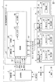
図1は、本実施形態に係る多機能電子機器1の構成を示す構成図である。なお、多機能電子機器1とは、例えばスマートウォッチである。図1に示すように、多機能電子機器1は、発振回路2、操作部3、主制御部4、第1指針駆動用モータユニット5、第2指針駆動用モータユニット6、第3指針駆動用モータユニット7、第4指針駆動用モータユニット8、付加ユニット9、および通信部10を備えている。また、多機能電子機器1は、利用者の腕等やその他の被固定箇所への装着用に用いられるベルト12(図4)を備えている。なお、多機能電子機器1は、端末20と通信して、情報の送受信を行うようにしてもよい。端末20は、例えばスマートフォン等の携帯端末、タブレット端末、パーソナルコンピュータ、携帯ゲーム機器等である。
なお、図1に示した例では、多機能電子機器1が、複数のユニットを備える例を示したが、多機能電子機器1は、複数のユニットのうち、少なくとも第1指針駆動用モータユニット5を備えていればよい。
Hereinafter, embodiments of the present invention will be described with reference to the drawings.
FIG. 1 is a configuration diagram showing a configuration of a multifunctional electronic device 1 according to the present embodiment. The multifunctional electronic device 1 is, for example, a smart watch. As shown in FIG. 1, the multi-function electronic device 1 includes an oscillation circuit 2, an operating unit 3, a main control unit 4, a first pointer driving motor unit 5, a second pointer driving motor unit 6, and a third pointer driving unit. A motor unit 7, a fourth pointer driving motor unit 8, an additional unit 9, and a communication unit 10 are provided. In addition, the multifunctional electronic device 1 includes a belt 12 (FIG. 4) that is used for wearing on a user's arm or the like or other fixed position. The multifunctional electronic device 1 may communicate with the terminal 20 to send and receive information. The terminal 20 is, for example, a mobile terminal such as a smartphone, a tablet terminal, a personal computer, a mobile game device, or the like.
In the example illustrated in FIG. 1, the multifunctional electronic device 1 includes the plurality of units, but the multifunctional electronic device 1 includes at least the first pointer driving motor unit 5 among the plurality of units. Should be provided.

主制御部4には、発振回路2、操作部3、通信部10が接続され、さらに第1指針駆動用モータユニット5が、5本(SS、SCLK、MOSI、MISO、BUSY)の信号線によって接続されている。   The main control unit 4 is connected to the oscillation circuit 2, the operation unit 3, and the communication unit 10, and the first pointer driving motor unit 5 is connected by five (SS, SCLK, MOSI, MISO, BUSY) signal lines. It is connected.

第1指針駆動用モータユニット5は、支持体51、入力部52、出力部53、発振回路54、記憶部55、制御部56、第1のモータ57、および第1指針58を備えている。第2指針駆動用モータユニット6は、支持体61、入力部62、第2のモータ67、および第2指針68を備えている。第3指針駆動用モータユニット7は、支持体71、入力部72、第3のモータ77、および第3指針78を備えている。第4指針駆動用モータユニット8は、支持体81、入力部82、第4のモータ87、および第4指針88を備えている。付加ユニット9は、支持体91、入力部92、および報知部99を備えている。なお、第1指針駆動用モータユニット5、第2指針駆動用モータユニット6、第3指針駆動用モータユニット7、第4指針駆動用モータユニット8、付加ユニット9のうち1つを特定しない場合は、単にユニットという。また、第1指針駆動用モータユニット5、第2指針駆動用モータユニット6、第3指針駆動用モータユニット7は、モータおよび指針を複数備えていてもよい。
また、第1指針駆動用モータユニット5には、第2指針駆動用モータユニット6、第3指針駆動用モータユニット7、第4指針駆動用モータユニット8、および付加ユニット9それぞれが、接続されている。
The first pointer driving motor unit 5 includes a support 51, an input section 52, an output section 53, an oscillation circuit 54, a storage section 55, a control section 56, a first motor 57, and a first pointer 58. The second pointer driving motor unit 6 includes a support 61, an input section 62, a second motor 67, and a second pointer 68. The third pointer driving motor unit 7 includes a support 71, an input section 72, a third motor 77, and a third pointer 78. The fourth pointer driving motor unit 8 includes a support 81, an input section 82, a fourth motor 87, and a fourth pointer 88. The addition unit 9 includes a support 91, an input unit 92, and a notification unit 99. When one of the first pointer driving motor unit 5, the second pointer driving motor unit 6, the third pointer driving motor unit 7, the fourth pointer driving motor unit 8, and the additional unit 9 is not specified, , Simply called a unit. The first pointer driving motor unit 5, the second pointer driving motor unit 6, and the third pointer driving motor unit 7 may include a plurality of motors and pointers.
The second pointer driving motor unit 6, the third pointer driving motor unit 7, the fourth pointer driving motor unit 8 and the additional unit 9 are connected to the first pointer driving motor unit 5, respectively. There is.

以下の説明では、各ユニット(第1指針駆動用モータユニット5、第2指針駆動用モータユニット6、第指針駆動用モータユニット7、第4指針駆動用モータユニット8、付加ユニット9)が、以下のように動作する例を説明する。なお、この動作例は一例であり、各ユニットの動作は、これに限られない。
第1指針駆動用モータユニット5と第2指針駆動用モータユニット6が時刻を表示し、第1指針駆動用モータユニット5が分を表示し、第2指針駆動用モータユニット6が時を表示する。第3指針駆動用モータユニット7と第4指針駆動用モータユニット8は、クロノグラフ機能による計時経過や計時結果を表示する。付加ユニット9は、利用者によって設定された時刻にアラーム音を報知する。
In the following description, each unit (first pointer driving motor unit 5, second pointer driving motor unit 6, fourth pointer driving motor unit 7, fourth pointer driving motor unit 8, additional unit 9) An example of operation as described above will be described. Note that this operation example is an example, and the operation of each unit is not limited to this.
The first pointer driving motor unit 5 and the second pointer driving motor unit 6 display the time, the first pointer driving motor unit 5 displays the minute, and the second pointer driving motor unit 6 displays the time. .. The third pointer driving motor unit 7 and the fourth pointer driving motor unit 8 display the elapsed time and the time measurement result by the chronograph function. The additional unit 9 reports an alarm sound at the time set by the user.

次に、各機能部について説明する。
発振回路2は、例えば32.768kHzの水晶振動子を備え、この水晶振動子が発生させた信号を分周して基準信号を生成し、生成した基準信号を主制御部4に出力する。なお、基準信号はクロック信号と同義である。
操作部3は、例えば竜頭、ボタン等である。操作部3は、利用者が操作した操作結果を主制御部4に出力する。操作結果には、例えば時刻合わせ指示、クロノグラフの計測開始指示、クロノグラフの計測終了指示、クロノグラフの表示をリセットする指示、アラームの設定時刻等が含まれている。
Next, each functional unit will be described.
The oscillator circuit 2 includes, for example, a crystal oscillator of 32.768 kHz, divides a signal generated by the crystal oscillator to generate a reference signal, and outputs the generated reference signal to the main control unit 4. The reference signal is synonymous with the clock signal.
The operation unit 3 is, for example, a crown or a button. The operation unit 3 outputs the operation result operated by the user to the main control unit 4. The operation result includes, for example, a time adjustment instruction, a chronograph measurement start instruction, a chronograph measurement end instruction, an instruction to reset the chronograph display, an alarm set time, and the like.

通信部10は、端末20と、例えばBluetooth(登録商標) LE(Low Energy)(以下、BLEという)規格の通信方式を用いて、情報の送受信を行う。また、受信する情報は、現在時刻を示す情報、メールを受信したことを示す情報、リマインダーの報知を示す情報等である。通信部10は、受信した情報を主制御部4に出力する。通信部10は、主制御部4が出力した情報を、外部装置へ送信する。主制御部4が出力する情報は、例えば外部装置から情報を受信したことに対する応答、多機能電子機器1が備えるユニット数を示す情報、多機能電子機器1が備える指針数を示す情報等である。なお、多機能電子機器1は、通信部10を備えていなくてもよい。   The communication unit 10 transmits / receives information to / from the terminal 20 by using, for example, a Bluetooth (registered trademark) LE (Low Energy) (hereinafter referred to as BLE) standard communication method. Further, the received information is information indicating the current time, information indicating that the mail has been received, information indicating the notification of the reminder, and the like. The communication unit 10 outputs the received information to the main control unit 4. The communication unit 10 transmits the information output by the main control unit 4 to an external device. The information output by the main control unit 4 is, for example, a response to information received from an external device, information indicating the number of units included in the multifunctional electronic device 1, information indicating the number of hands included in the multifunctional electronic device 1, and the like. .. The multifunctional electronic device 1 does not have to include the communication unit 10.

主制御部4は、例えばCPU(中央演算装置)であり、発振回路2が出力した基準信号を用いて、第1指針駆動用モータユニット5、第2指針駆動用モータユニット6、第3指針駆動用モータユニット7、第4指針駆動用モータユニット8を運針させて時刻表示させるコマンドを生成し、生成したコマンドを第1指針駆動用モータユニット5に出力する。コマンドは、例えば8bit(ビット)の情報である。また、主制御部4は、操作部3が出力した操作指示に応じて、第1指針駆動用モータユニット5、第2指針駆動用モータユニット6、第3指針駆動用モータユニット7、第4指針駆動用モータユニット8、および付加ユニット9の中から使用するユニットを選択し、選択したユニットに対する制御指示であるコマンドを生成し、生成したコマンドを第1指針駆動用モータユニット5に出力する。なお、コマンドには、制御対象のユニットを示す情報が含まれ、ユニット内に複数の制御対象がある場合、その制御対象を示す情報が含まれている。なお、コマンドについては後述する。なお、CPUは、MPU(マイクロプロセッサユニット)やMCU(マイクロコントローラユニット)を含む概念として表記するものであり、本発明の機能、作用、効果のいずれかを達成できるものであればよい。   The main controller 4 is, for example, a CPU (central processing unit), and uses the reference signal output from the oscillation circuit 2 to drive the first pointer driving motor unit 5, the second pointer driving motor unit 6, and the third pointer driving. A command for moving the driving motor unit 7 and the fourth pointer driving motor unit 8 to display the time is generated, and the generated command is output to the first pointer driving motor unit 5. The command is, for example, 8-bit (bit) information. In addition, the main control unit 4 responds to the operation instruction output from the operation unit 3 by driving the first pointer driving motor unit 5, the second pointer driving motor unit 6, the third pointer driving motor unit 7, and the fourth pointer. A unit to be used is selected from the drive motor unit 8 and the additional unit 9, a command which is a control instruction for the selected unit is generated, and the generated command is output to the first pointer drive motor unit 5. The command includes information indicating the unit to be controlled, and when there are a plurality of control targets in the unit, the command includes information indicating the control target. The command will be described later. The CPU is described as a concept including an MPU (microprocessor unit) and an MCU (microcontroller unit), and may be any one that can achieve any of the functions, actions, and effects of the present invention.

次に、第1指針駆動用モータユニット5について説明する。
第1指針駆動用モータユニット5は、例えば第1指針58が、指針軸501(図4参照)に配置されて、分を表示する時刻表示可能なユニットである。第1指針駆動用モータユニット5は、主制御部4がコマンドに応じて、各ユニットが備えるモータ(57、67、87)または報知部99を駆動する駆動信号を、記憶部55が記憶している情報を用いて生成する。第1指針駆動用モータユニット5は、コマンドに含まれる制御対象のユニットを示す情報が自ユニットである場合、生成した駆動信号によって第1指針駆動用モータユニット5の第1指針58を運針する。第1指針駆動用モータユニット5は、コマンドに含まれる制御対象のユニット(第2指針駆動用モータユニット6、第3指針駆動用モータユニット7、第4指針駆動用モータユニット8、および付加ユニット9)に、生成したコマンドを出力する。
Next, the first pointer driving motor unit 5 will be described.
The first pointer driving motor unit 5 is, for example, a unit capable of displaying time, in which the first pointer 58 is arranged on the pointer shaft 501 (see FIG. 4) and displays the minutes. In the first pointer driving motor unit 5, the storage unit 55 stores a driving signal for driving the motors (57, 67, 87) included in each unit or the notification unit 99 in response to a command by the main control unit 4. It is generated using existing information. When the information indicating the unit to be controlled included in the command is its own unit, the first pointer driving motor unit 5 moves the first pointer 58 of the first pointer driving motor unit 5 by the generated drive signal. The first pointer driving motor unit 5 includes units to be controlled included in the command (second pointer driving motor unit 6, third pointer driving motor unit 7, fourth pointer driving motor unit 8, and additional unit 9). ) Output the generated command.

支持体51は、基板、ベースとなる地板、地板上に配置された部品を反対側から抑える受板、その他ケース部等を含む。地板上に基板が配置され、基板上に、配線、入力部52、出力部53、発振回路54、記憶部55、制御部56、第1のモータ57、モータからのトルクを伝達する歯車列である輪列等が配置される。これら部品を、受板により留めることでユニットが組み立てられる。なお、地板には、後述する接続端子となる電極が配置され、この電極が内部の電子部品とユニット外部とを電気的に導通する役目を担う。
また、入力部52は、主制御部4との例えば接続端子である。
The support body 51 includes a substrate, a base plate that serves as a base, a receiving plate that holds components arranged on the base plate from the opposite side, and a case portion. The board is arranged on the main plate, and the wiring, the input section 52, the output section 53, the oscillation circuit 54, the storage section 55, the control section 56, the first motor 57, and the gear train for transmitting the torque from the motor are arranged on the board. A train wheel or the like is arranged. A unit is assembled by fastening these parts with a backing plate. An electrode serving as a connection terminal, which will be described later, is arranged on the main plate, and the electrode plays a role of electrically connecting an electronic component inside and the outside of the unit.
The input unit 52 is, for example, a connection terminal with the main control unit 4.

出力部53は、第2指針駆動用モータユニット6、第3指針駆動用モータユニット7、第4指針駆動用モータユニット8、および付加ユニット9との例えば接続端子である。出力部53は、第1の出力部53−1、第2の出力部53−2、第3の出力部53−3、および第4の出力部53−4を備える。第1の出力部53−1には第2指針駆動用モータユニット6が接続され、第2の出力部53−2には第3指針駆動用モータユニット7が接続され、第3の出力部53−3には第4指針駆動用モータユニット8が接続され、第4の出力部53−4には付加ユニット9が接続される。なお、各接続端子に接続されるユニットは、予め定められているか、多機能電子機器1の製造または組み立て時に製造者によって設定される。
発振回路54は、制御部56が用いる基準信号を生成し、生成した基準信号を制御部56に出力する。
The output unit 53 is, for example, a connection terminal with the second pointer driving motor unit 6, the third pointer driving motor unit 7, the fourth pointer driving motor unit 8, and the additional unit 9. The output unit 53 includes a first output unit 53-1, a second output unit 53-2, a third output unit 53-3, and a fourth output unit 53-4. The second output unit 53-1 is connected to the second pointer driving motor unit 6, the second output unit 53-2 is connected to the third pointer driving motor unit 7, and the third output unit 53 is connected. -4 is connected to the fourth pointer driving motor unit 8, and the fourth output portion 53-4 is connected to the additional unit 9. The unit connected to each connection terminal is predetermined or set by the manufacturer at the time of manufacturing or assembling the multifunctional electronic device 1.
The oscillator circuit 54 generates a reference signal used by the control unit 56 and outputs the generated reference signal to the control unit 56.

記憶部55は、第1指針駆動用モータユニット5に接続されているユニットの種類、ユニットの個数等の情報を記憶する。ここで、ユニットの種類とは、1つのモータと1つの指針を備えるユニット、2つのモータと2つの指針を備えるユニット、報知部を備えるユニットである。なお、このようなユニットに関する情報は、多機能電子機器1の組み立て時、または組み立て後に製造者が記憶部55に書き込みようにしてもよい。または、ユニットに関する情報を、例えば端末20であるパーソナルコンピュータから通信部10へ送信し、主制御部4は、通信部10が受信したユニットに関する情報を制御部56へ出力する。そして、制御部56は、主制御部4が出力したユニットに関する情報を記憶部55に書き込むようにしてもよい。また、記憶部55は、主制御部4が出力するコマンドに対応するモータ(57、67、77、87)または報知部99の駆動信号を記憶する。   The storage unit 55 stores information such as the type of unit connected to the first pointer driving motor unit 5 and the number of units. Here, the type of unit is a unit including one motor and one pointer, a unit including two motors and two pointers, and a unit including a notification unit. The information about such a unit may be written in the storage unit 55 by the manufacturer at the time of assembling the multifunctional electronic device 1 or after the assembling. Alternatively, the information about the unit is transmitted from the personal computer, which is the terminal 20, to the communication unit 10, and the main control unit 4 outputs the information about the unit received by the communication unit 10 to the control unit 56. Then, the control unit 56 may write the information about the unit output by the main control unit 4 into the storage unit 55. The storage unit 55 also stores drive signals for the motors (57, 67, 77, 87) or the notification unit 99 corresponding to the commands output by the main control unit 4.

制御部56は、主制御部4が出力したコマンドに応じて、対応するユニットの対応するモータまたは報知部を駆動する駆動信号(駆動パルスともいう)を、記憶部55が記憶する情報を用いて生成する。制御部56は、コマンドが自ユニットに対するものである場合、生成した駆動信号を対応する第1のモータ57に出力する。制御部56は、コマンドが他のユニットに対するものである場合、生成した駆動信号を対応するユニット(第2指針駆動用モータユニット6、第3指針駆動用モータユニット7、第4指針駆動用モータユニット8、および付加ユニット9)に出力する。   The control unit 56 uses the information stored in the storage unit 55 to generate a drive signal (also referred to as a drive pulse) for driving the corresponding motor or the notification unit of the corresponding unit according to the command output from the main control unit 4. To generate. When the command is for its own unit, the control unit 56 outputs the generated drive signal to the corresponding first motor 57. When the command is for another unit, the control unit 56 applies the generated drive signal to the corresponding unit (the second pointer driving motor unit 6, the third pointer driving motor unit 7, the fourth pointer driving motor unit). 8 and the additional unit 9).

第1のモータ57は、ステッピングモータである。第1のモータ57は、制御部56が出力した駆動信号に応じて、例えばギア(不図示)を介して第1指針58を駆動する。
第1指針58は、例えば短針であり、短針は例えば時針であり、支持体51に回転可能に支持されている。
The first motor 57 is a stepping motor. The first motor 57 drives the first pointer 58 via, for example, a gear (not shown) according to the drive signal output by the control unit 56.
The first pointer 58 is, for example, a short hand, and the short hand is, for example, an hour hand, and is rotatably supported by the support body 51.

次に、第2指針駆動用モータユニット6〜第4指針駆動用モータユニット8について説明する。
第2指針駆動用モータユニット6は、例えば時を表示するユニットである。第2指針駆動用モータユニット6は、第1指針駆動用モータユニット5が出力した駆動信号に応じて、第2指針68を駆動する。第3指針駆動用モータユニット7と第4指針駆動用モータユニット8は、例えばクロノグラフの計時経過や計時結果を表示するユニットである。第3指針駆動用モータユニット7は、第1指針駆動用モータユニット5が出力した駆動信号に応じて、第3指針78を駆動し、第4指針駆動用モータユニット8は、第1指針駆動用モータユニット5が出力した駆動信号に応じて、第4指針88を駆動する。
Next, the second pointer driving motor unit 6 to the fourth pointer driving motor unit 8 will be described.
The second pointer driving motor unit 6 is, for example, a unit that displays time. The second pointer driving motor unit 6 drives the second pointer 68 according to the drive signal output from the first pointer driving motor unit 5. The third pointer driving motor unit 7 and the fourth pointer driving motor unit 8 are units that display, for example, a chronograph's timekeeping progress and a timekeeping result. The third pointer driving motor unit 7 drives the third pointer 78 according to the drive signal output from the first pointer driving motor unit 5, and the fourth pointer driving motor unit 8 drives the first pointer driving motor. The fourth pointer 88 is driven according to the drive signal output from the motor unit 5.

支持体61、支持体71、支持体81それぞれは、基板、ベースとなる地板、地板上に配置された部品を反対側から抑える受板、その他ケース部等を含む。地板上に基板が配置され、基板上に、例えば配線、接続部(62、72、82のいずれか)、モータ(接続部に対応する67、77、87のいずれか)、モータからのトルクを伝達する歯車列である輪列等が配置される。これら部品を、受板により留めることでユニットが組み立てられる。   Each of the support body 61, the support body 71, and the support body 81 includes a substrate, a base plate serving as a base, a receiving plate that suppresses components arranged on the base plate from the opposite side, and other case portions. The substrate is arranged on the main plate, and the wiring, the connection portion (any one of 62, 72, 82), the motor (any one of 67, 77, 87 corresponding to the connection portion), and the torque from the motor are arranged on the substrate. A train wheel or the like, which is a gear train for transmission, is arranged. A unit is assembled by fastening these parts with a backing plate.

第2のモータ67、第3のモータ77、および第4のモータ87は、ステッピングモータである。第2のモータ67は、第1指針駆動用モータユニット5が出力した駆動信号に応じて、例えばギア(不図示)を介して第2指針68を駆動する。第3のモータ77は、第1指針駆動用モータユニット5が出力した駆動信号に応じて、例えばギア(不図示)を介して第3指針78を駆動する。第4のモータ87は、第1指針駆動用モータユニット5が出力した駆動信号に応じて、例えばギア(不図示)を介して第4指針88を駆動する。   The second motor 67, the third motor 77, and the fourth motor 87 are stepping motors. The second motor 67 drives the second pointer 68 via, for example, a gear (not shown) according to the drive signal output from the first pointer driving motor unit 5. The third motor 77 drives the third pointer 78 via, for example, a gear (not shown) according to the drive signal output from the first pointer driving motor unit 5. The fourth motor 87 drives the fourth pointer 88 via, for example, a gear (not shown) according to the drive signal output from the first pointer driving motor unit 5.

第2指針68は、例えば長針であり、長針は例えば分針であり、支持体61に回転可能に支持されている。第3指針78は、指針であり、支持体71に回転可能に支持されている。第4指針88は、指針であり、支持体81に回転可能に支持されている。また、第3指針78および第4指針88は、例えばクロノグラフ計時時に、第3指針78が分単位の計時経過を表示し、第4指針88が秒単位の計時経過を表示する。   The second pointer 68 is, for example, a long hand, and the long hand is, for example, a minute hand, and is rotatably supported by the support body 61. The third pointer 78 is a pointer and is rotatably supported by the support 71. The fourth pointer 88 is a pointer and is rotatably supported by the support 81. Further, the third pointer 78 and the fourth pointer 88 display, for example, the elapsed time in minutes by the third pointer 78 and the elapsed time in seconds by the fourth pointer 88, for example, during chronograph timekeeping.

次に、付加ユニット9について説明する。
付加ユニット9は、報知を行うユニットである。付加ユニット9は、第1指針駆動用モータユニット5が出力した駆動信号に応じて、報知部99を駆動する。
支持体91は、基板、ベースとなる地板、地板上に配置された部品を反対側から抑える受板、その他ケース部等を含む。地板上に基板が配置され、基板上に、例えば配線、入力部92、報知部99等が配置される。
報知部99は、例えばブザー(音発生素子)であり、第1指針駆動用モータユニット5が出力した駆動信号に応じて、音を報知する。なお、報知部99は、ランプ(発光素子)、振動素子等であってもよい。
Next, the additional unit 9 will be described.
The additional unit 9 is a unit that performs notification. The additional unit 9 drives the notification unit 99 according to the drive signal output from the first pointer driving motor unit 5.
The support 91 includes a substrate, a base plate that serves as a base, a receiving plate that holds components arranged on the base plate from the opposite side, and other case portions. The substrate is arranged on the main plate, and the wiring, the input unit 92, the notification unit 99, and the like are arranged on the substrate.
The notification unit 99 is, for example, a buzzer (sound generation element), and notifies the sound according to the drive signal output from the first pointer driving motor unit 5. The notification unit 99 may be a lamp (light emitting element), a vibration element, or the like.

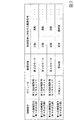
次に、記憶部55が記憶する情報の一例を説明する。
図2は、本実施形態に係る記憶部55が記憶する情報の一例を示す図である。図2に示すように、記憶部55は、接続端子に、接続されるユニット、制御対象、制御指示に対応する駆動信号を対応付けて記憶する。記憶部55は、例えば、第1の接続端子である第1の出力部53−1に、接続されるユニットとして第2指針駆動用モータユニット6、制御対象として第2のモータ67、コマンドに対応する駆動信号として正転と逆転等を対応付けて記憶する。
なお、主制御部4が出力するコマンドには、制御対象のユニット、制御対象のモータまたは報知部、および制御指示が含まれている。また、制御指示には、制御対象がモータの場合、運針方向(正転、逆転)、運針数(正転させるステップ数、または逆転させるステップ数)等が含まれている。なお、ステップ数とは、ステッピングモータであるモータ(57、67、77、87)を回転させるときのステップ数である。また、制御指示には、制御対象が報知部99の場合、単音を発する指示、連続音を発する指示等が含まれている。
Next, an example of information stored in the storage unit 55 will be described.
FIG. 2 is a diagram showing an example of information stored in the storage unit 55 according to the present embodiment. As illustrated in FIG. 2, the storage unit 55 stores the connection terminal, the unit to be connected, the control target, and the drive signal corresponding to the control instruction in association with each other. The storage unit 55 corresponds to, for example, the first output unit 53-1 that is the first connection terminal, the second pointer driving motor unit 6 as a unit to be connected, the second motor 67 as a control target, and a command. The forward rotation, the reverse rotation, and the like are stored in association with each other as the drive signal to be executed.
The command output by the main control unit 4 includes a unit to be controlled, a motor or notification unit to be controlled, and a control instruction. When the control target is a motor, the control instruction includes the hand movement direction (normal rotation, reverse rotation), the number of needle movements (the number of steps for forward rotation or the number of steps for reverse rotation), and the like. The number of steps is the number of steps when rotating the motors (57, 67, 77, 87) that are stepping motors. When the control target is the notification unit 99, the control instruction includes an instruction to emit a single tone, an instruction to emit a continuous tone, and the like.

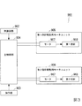
図3に示すように、従来の多機能電子機器901では、各ユニットがモータと指針のみを有し、制御部を有していない。このため、主制御部904が各モータ(957、967)の駆動信号を生成して駆動する必要がある。この駆動信号は、主制御部904の制御プログラムの作成者が作成する必要がある。しかしながら、ステッピングモータの制御には、ユニットに搭載されているステッピングモータの特性の理解、ステッピングモータの駆動手法(正転、逆転、停止、脱調予防等)の理解が必要である。このため、例えば、第1指針駆動用モータユニット905と第2指針駆動用モータユニット906を用いて、スマートウォッチ(多機能電子機器)を構成しようとした場合、主制御部904の制御プログラムの作成者の負担が多い。さらに、図3に示したように、主制御部904は、第1指針駆動用モータユニット905と第2指針駆動用モータユニット906を駆動する必要があったので、主制御部904の負担が多かった。また、仮に多機能電子機器901が通信部(不図示)を有し、スマートフォン(多機能携帯電話)(不図示)との通信を行う場合、一般的な多機能電子機器の処理と比較して主制御部904の処理が多くなる。このため、従来技術の多機能電子機器901では、例えばユニット数が多くなりユニットを駆動する処理が多くなると、スマートフォンとの通信に支障が生じ、スマートフォンとの通信が多くなるとユニットの制御に支障が出る場合があった。   As shown in FIG. 3, in the conventional multifunctional electronic device 901, each unit has only a motor and a pointer, and does not have a control unit. Therefore, the main controller 904 needs to generate and drive the drive signals of the motors (957, 967). This drive signal needs to be created by the creator of the control program of the main control unit 904. However, in order to control the stepping motor, it is necessary to understand the characteristics of the stepping motor mounted in the unit and the driving method of the stepping motor (forward rotation, reverse rotation, stop, step out prevention, etc.). Therefore, for example, when an attempt is made to configure a smart watch (multifunctional electronic device) using the first pointer driving motor unit 905 and the second pointer driving motor unit 906, a control program for the main controller 904 is created. Burden on the person. Further, as shown in FIG. 3, the main controller 904 needs to drive the first pointer driving motor unit 905 and the second pointer driving motor unit 906, so that the main controller 904 has a large load. It was Further, if the multifunctional electronic device 901 has a communication unit (not shown) and communicates with a smartphone (multifunctional mobile phone) (not shown), compared with the processing of a general multifunctional electronic device. The processing of the main control unit 904 increases. Therefore, in the multi-function electronic device 901 of the related art, for example, when the number of units increases and the number of processes for driving the units increases, the communication with the smartphone is disturbed, and when the communication with the smartphone increases, the control of the unit is disturbed. There was a case to come out.

一方、本実施形態では、主制御部4は、第1指針駆動用モータユニット5のみに駆動信号ではなくコマンドを出力することで、他のユニットも制御することができる。この結果、主制御部4の制御プログラムの作成者は、動作させたいユニットを示す情報を埋め込んだコマンドを第1指針駆動用モータユニットに送信する制御プログラムを作成すればよいので、作成者の負担が軽減される。さらに、主制御部4は、複数のユニットがあっても、第1指針駆動用モータユニット5のみと情報のやりとりを行うため、主制御部4の負担が軽減される。さらに、本実施形態によれば、主制御部4の制御プログラム作成者は、ステッピングモータの特性や駆動信号の生成方法を理解する必要が無く、目標時刻の指示や、カウントダウンタイマーモード等のモード変更指示等を指示するだけでよいので、制御プログラム作成者のプログラム作成における負荷を大幅に軽減することができる。   On the other hand, in the present embodiment, the main control unit 4 can control other units by outputting a command instead of a drive signal only to the first pointer driving motor unit 5. As a result, the creator of the control program of the main control unit 4 may create a control program for sending a command in which information indicating the unit to be operated is embedded to the first pointer driving motor unit, and therefore the creator's burden. Is reduced. Further, since the main control unit 4 exchanges information with only the first pointer driving motor unit 5 even if there are a plurality of units, the load on the main control unit 4 is reduced. Furthermore, according to the present embodiment, the control program creator of the main control unit 4 does not need to understand the characteristics of the stepping motor or the method of generating the drive signal, and can change the target time or change the mode such as the countdown timer mode. Since it is only necessary to give an instruction or the like, it is possible to significantly reduce the load of the control program creator in creating the program.

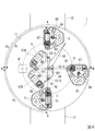
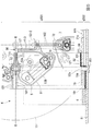
次に、基体11上に主制御部4、第1指針駆動用モータユニット5、第2指針駆動用モータユニット6、第3指針駆動用モータユニット7、および第4指針駆動用モータユニット8を配置した例を説明する。
図4は、本実施形態に係る基体11上に主制御部4、第1指針駆動用モータユニット5、第2指針駆動用モータユニット6、第3指針駆動用モータユニット7、および第4指針駆動用モータユニット8を配置した一例を示す図である。なお、図4において、各ユニットにおいて、各指針等を省略している。なお、図4に示す例は、多機能電子機器1が、4つのユニット(第1指針駆動用モータユニット5、第2指針駆動用モータユニット6、第3指針駆動用モータユニット7、および第4指針駆動用モータユニット8)を備える例である。なお、図4では、発振回路2、操作部3、通信部10等の図示を省略している。また、図4に示す例は、第1指針駆動用モータユニット5が2つのモータ(モータ57A、モータ57B)、2つの指針(指針58A、指針58B)を備える例である。
また、本実施形態では、線ABを中心に時計回りの位置A〜位置Dそれぞれを、12時の位置、3時の位置、6時の位置、9時の位置という。
Next, the main controller 4, the first pointer driving motor unit 5, the second pointer driving motor unit 6, the third pointer driving motor unit 7, and the fourth pointer driving motor unit 8 are arranged on the base 11. An example will be described.
FIG. 4 shows the main controller 4, the first pointer driving motor unit 5, the second pointer driving motor unit 6, the third pointer driving motor unit 7, and the fourth pointer driving on the base body 11 according to the present embodiment. It is a figure which shows an example which has arrange | positioned the motor unit 8 for. In addition, in FIG. 4, each pointer and the like are omitted in each unit. In the example shown in FIG. 4, the multifunctional electronic device 1 has four units (first pointer driving motor unit 5, second pointer driving motor unit 6, third pointer driving motor unit 7, and fourth pointer driving motor unit 5). This is an example including a pointer driving motor unit 8). In FIG. 4, the oscillator circuit 2, the operation unit 3, the communication unit 10 and the like are omitted. Further, the example shown in FIG. 4 is an example in which the first pointer driving motor unit 5 includes two motors (motor 57A, motor 57B) and two pointers (pointers 58A, 58B).
Further, in the present embodiment, each of the positions A to D clockwise around the line AB is referred to as a 12 o'clock position, a 3 o'clock position, a 6 o'clock position, and a 9 o'clock position.

図4に示すように、多機能電子機器1の外部から視認可能な文字盤13に基体11が取り付けられ、基体11上には、略中心に第1指針駆動用モータユニット5が配置され、略9時の位置に主制御部4が配置され、略12時の位置に第2指針駆動用モータユニット6が配置され、略3時の位置に第4指針駆動用モータユニット8が配置され、略6時の位置に第3指針駆動用モータユニット7が配置されている。多機能電子機器1の基体11上、入力部52と第1の出力部53−1に接続される基体11上の主接続部の配線パターン(不図示)とは、第1指針58の軸(指針軸501)を中心として、略90度離間して配置されている。また、入力部52と第2の出力部53−2に接続される基体11上の主接続部102(図5)の配線パターンとは、第1指針58の軸(指針軸501)を中心として、略−90度離間して配置されている。さらに、入力部52と第3の出力部53−3に接続される基体11上の主接続部103a,103b(図6)の配線パターンとは、第1指針58の軸(指針軸501)を中心として、略180度離間して配置されている。ここで、第1の出力部53−1、第2の出力部53−2、第3の出力部53−3のうち1つを特定しない場合は、単に出力部53という。すなわち、本実施形態では、入力部52と出力部53に接続される基体11上の主接続部(配線パターン)とは、第1指針58の軸(指針軸501)を中心として、30度以上180度以下離間して配置されている。なお、図4に示した各指針(第1指針58、第2指針68、第3指針78、第4指針88)の位置は、一例である。   As shown in FIG. 4, the base 11 is attached to a dial 13 which is visible from the outside of the multi-function electronic device 1, and the first pointer driving motor unit 5 is arranged substantially at the center of the base 11, The main controller 4 is arranged at the 9 o'clock position, the second pointer driving motor unit 6 is arranged at the substantially 12 o'clock position, and the fourth pointer driving motor unit 8 is arranged at the substantially 3 o'clock position. The third pointer driving motor unit 7 is arranged at the 6 o'clock position. On the base 11 of the multifunctional electronic device 1, the wiring pattern (not shown) of the main connection portion on the base 11 connected to the input unit 52 and the first output unit 53-1 is the axis of the first pointer 58 ( The pointer shaft 501) is arranged at a distance of approximately 90 degrees. Further, the wiring pattern of the main connecting portion 102 (FIG. 5) on the base 11 connected to the input portion 52 and the second output portion 53-2 is centered on the axis of the first pointer 58 (pointer shaft 501). , Are separated by about −90 degrees. Furthermore, the wiring pattern of the main connecting portions 103a and 103b (FIG. 6) on the base 11 connected to the input portion 52 and the third output portion 53-3 is the axis of the first pointer 58 (pointer shaft 501). As the center, they are arranged approximately 180 degrees apart. Here, when one of the first output unit 53-1, the second output unit 53-2, and the third output unit 53-3 is not specified, it is simply referred to as the output unit 53. That is, in the present embodiment, the main connecting portion (wiring pattern) on the base body 11 connected to the input portion 52 and the output portion 53 is 30 degrees or more around the axis of the first pointer 58 (pointer shaft 501). They are spaced apart by 180 degrees or less. It should be noted that the positions of the respective pointers (first pointer 58, second pointer 68, third pointer 78, fourth pointer 88) shown in FIG. 4 are examples.

また、第1指針駆動用モータユニット5は、支持体51上に入力部52、第1の出力部53−1〜第3の出力部53−3が形成され、支持体51上にモータ57Aとモータ57Bが取り付けられている。なお、本実施形態において、基体上とは、基体の表側と裏側のうちの少なくとも1つ側である。例えば、入力部52は、支持体51の裏側に形成されていてもよく、表側に形成されていてもよい。入力部52は、主制御部4との接続部である。また、第1の出力部53−1は、第2指針駆動用モータユニット6との接続部であり、第2の出力部53−2は、第3指針駆動用モータユニット7との接続部であり、第3の出力部53−3は、第4指針駆動用モータユニット8との接続部である。   Further, in the first pointer driving motor unit 5, the input section 52 and the first output section 53-1 to the third output section 53-3 are formed on the support body 51, and the motor 57A and the motor 57A are provided on the support body 51. The motor 57B is attached. In addition, in the present embodiment, “on the substrate” means at least one of the front side and the back side of the substrate. For example, the input section 52 may be formed on the back side of the support body 51 or may be formed on the front side. The input unit 52 is a connection unit with the main control unit 4. Further, the first output portion 53-1 is a connecting portion with the second pointer driving motor unit 6, and the second output portion 53-2 is a connecting portion with the third pointer driving motor unit 7. Yes, the third output portion 53-3 is a connection portion with the fourth pointer driving motor unit 8.

また、図4に示すように、基体11上には、第1指針駆動用モータユニット5が略中央部に配置され、第2指針駆動用モータユニット(第2指針駆動用モータユニット6、第3指針駆動用モータユニット7、第4指針駆動用モータユニット8)が第1指針駆動用モータユニット5より周辺側に配置され、主接続部(基体11上の配線パターン、第1の出力部53−1と入力部62との配線パターン、第2の出力部53−2と入力部72との配線パターン102、第3の出力部53−3と入力部82との配線パターン103a,103b)が中央部から周辺側に向かう方向に配置されている。   Further, as shown in FIG. 4, the first pointer driving motor unit 5 is arranged on the substrate 11 at a substantially central portion, and the second pointer driving motor unit (the second pointer driving motor unit 6 and the third pointer driving motor unit 6 is provided). The pointer driving motor unit 7 and the fourth pointer driving motor unit 8) are arranged on the peripheral side of the first pointer driving motor unit 5, and the main connection portion (the wiring pattern on the base 11 and the first output portion 53- 1 is a wiring pattern between the input unit 62 and the input unit 62, a wiring pattern 102 between the second output unit 53-2 and the input unit 72, and wiring patterns 103a and 103b between the third output unit 53-3 and the input unit 82 are in the center. It is arranged in the direction from the section toward the peripheral side.

次に、主制御部4と第1指針駆動用モータユニット5との接続、第1指針駆動用モータユニット5と他のユニットとの接続について説明する。
図5は、本実施形態に係る主制御部4と第1指針駆動用モータユニット5との接続、第1指針駆動用モータユニット5と第3指針駆動用モータユニット7との接続を示す図である。図5において、符号g501が示す領域は平面図であり、符号g502が示す領域は平面図のII−IIの切断線における断面図である。なお、図5に示した接続関係を示す図は、図4の一部を抜き出して示したものである。
Next, the connection between the main controller 4 and the first pointer driving motor unit 5 and the connection between the first pointer driving motor unit 5 and other units will be described.
FIG. 5 is a diagram showing the connection between the main controller 4 and the first pointer driving motor unit 5 and the connection between the first pointer driving motor unit 5 and the third pointer driving motor unit 7 according to the present embodiment. is there. In FIG. 5, a region indicated by reference sign g501 is a plan view, and a region indicated by reference sign g502 is a cross-sectional view taken along a section line II-II in the plan view. It should be noted that the diagram showing the connection relationship shown in FIG. 5 is obtained by extracting a part of FIG.

符号g501が示す領域のように、主制御部4は、基体11上で、5本(SS、SCLK、MOSI、MISO、BUSY)の配線パターンである副接続部101によって第1指針駆動用モータユニット5の入力部52が接続されている。さらに、入力部52は、支持体51上で、5本の配線パターンである接続部111によって制御部56が接続されている。制御部56は、支持体51上で、2本の配線パターンである接続部112によってモータ57Bが接続され、2本の配線パターンである接続部113によって第3の出力部53−3が接続されている。
また、第2の出力部53−2は、基体11上で、2本の配線パターンである主接続部102によって第3指針駆動用モータユニット7の入力部72が接続されている。
As indicated by a region indicated by reference sign g501, the main control unit 4 uses the sub-connection unit 101, which is a wiring pattern of five lines (SS, SCLK, MOSI, MISO, BUSY) on the base 11, to drive the first pointer driving motor unit. 5 input units 52 are connected. Further, the input section 52 is connected to the control section 56 on the support body 51 by the connection sections 111 which are five wiring patterns. In the control unit 56, on the support body 51, the motor 57B is connected by the connecting portion 112 which is two wiring patterns, and the third output portion 53-3 is connected by the connecting portion 113 which is two wiring patterns. ing.
Further, the second output section 53-2 is connected to the input section 72 of the third pointer driving motor unit 7 on the base 11 by the main connecting section 102 which is two wiring patterns.

符号g502が示す領域のように、配線パターンである副接続部101は、基体11上に設けられている。主制御部4は、基体11上に取り付けられている。また、入力部52は、基体11と向き合う支持体51の裏面51cに設けられている。配線パターンである接続部111は、支持体51の裏面51cと反対側の表面51bに設けられ、制御部56が支持体51の表面51b取り付けられている。入力部52と接続部111とは、スルーホール121等を介して接続されている。また、基体11は孔11aを備え、支持体51の入力部52は孔52aを備える。
支持体51は、孔11aと孔52aとを貫通する螺旋(ネジ)151によって基体11に取り付けられることで、副接続部101と入力部52が接触することで導通する。
The sub-connecting portion 101, which is a wiring pattern, is provided on the base 11 as in the region indicated by reference sign g502. The main controller 4 is mounted on the base 11. The input section 52 is provided on the back surface 51c of the support body 51 facing the base 11. The connection portion 111, which is a wiring pattern, is provided on the front surface 51b of the support 51 opposite to the back surface 51c, and the control portion 56 is attached to the front surface 51b of the support 51. The input section 52 and the connecting section 111 are connected to each other via a through hole 121 or the like. Further, the base body 11 has a hole 11a, and the input portion 52 of the support 51 has a hole 52a.
The support body 51 is attached to the base body 11 by a helix (screw) 151 penetrating the holes 11a and 52a, so that the sub-connecting portion 101 and the input portion 52 come into contact with each other to establish electrical conduction.

接続部112と接続部113は、支持体51の表面51b上に設けられている。接続部113と第2の出力部53−2とは、スルーホール等を介して接続されている。第2の出力部53−2は、支持体51の裏面52cに設けられている。
配線パターンである主接続部102は、基体11上に設けられている。第2の出力部53−2も孔を備え、螺旋によって基体11に取り付けられることで、第2の出力部53−2と主接続部102とが接触する。
入力部72は、支持体71が基体11に向き合う裏面に設けられている。また、支持体71も孔を備え、支持体71は、螺旋によって基体11に取り付けられることで、主接続部102と入力部72が接触することで導通する。
The connection portion 112 and the connection portion 113 are provided on the surface 51b of the support 51. The connection portion 113 and the second output portion 53-2 are connected via a through hole or the like. The second output section 53-2 is provided on the back surface 52c of the support body 51.
The main connection portion 102, which is a wiring pattern, is provided on the base 11. The second output portion 53-2 also has a hole and is attached to the base 11 by a spiral, so that the second output portion 53-2 and the main connecting portion 102 are in contact with each other.
The input section 72 is provided on the back surface of the support 71 facing the base 11. Further, the support body 71 also has holes, and the support body 71 is attached to the base body 11 by a spiral, so that the main connection portion 102 and the input portion 72 come into contact with each other to establish electrical conduction.

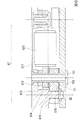
次に、基体11へのユニットの取り付け例を説明する。
図6は、本実施形態に係る基体11への第2指針駆動用モータユニット6の取り付け例を示す図である。
図6に示すように、第2のモータ67は、ステータ671、コイル672、コイル磁芯673、フレキシブル基板674、電極パターン675、スペーサ676、入力部52、およびユニットカバー677を備える。なお、電極パターン675は、コイル磁芯673に取り付けられているフレキシブル基板674上、スペーサ676の上面に設けられている。また、スペーサ676は、上面と下面とがスルーホール等で接続され、電極パターン675と入力部52とが導通している。
第2指針駆動用モータユニット6は、螺旋151によって基体11に取り付けられることで、基体11上の配線パターンである主接続部102と入力部52とが接触することで導通する。
Next, an example of attaching the unit to the base 11 will be described.
FIG. 6 is a diagram showing an example of attachment of the second pointer driving motor unit 6 to the base body 11 according to the present embodiment.
As shown in FIG. 6, the second motor 67 includes a stator 671, a coil 672, a coil magnetic core 673, a flexible substrate 674, an electrode pattern 675, a spacer 676, an input section 52, and a unit cover 677. The electrode pattern 675 is provided on the flexible substrate 674 attached to the coil magnetic core 673 and on the upper surface of the spacer 676. Further, the spacer 676 has an upper surface and a lower surface connected to each other through a through hole or the like, and the electrode pattern 675 and the input section 52 are electrically connected to each other.
The second pointer driving motor unit 6 is attached to the base body 11 by the helix 151, so that the main connection portion 102, which is a wiring pattern on the base body 11, and the input portion 52 are brought into contact with each other, so that they are electrically connected.

上述したように、本実施形態では、基体11にユニットを螺旋止めすることで、基体11上の配線パターン(電極パターン)を介して、主制御部4と第1指針駆動用モータユニット5を接続し、第1指針駆動用モータユニット5の制御部56と他のユニットのモータとを接続することができる。   As described above, in this embodiment, the main controller 4 and the first pointer driving motor unit 5 are connected via the wiring pattern (electrode pattern) on the base 11 by screwing the unit to the base 11. However, the control unit 56 of the first pointer driving motor unit 5 and the motors of other units can be connected.

以上のように、本実施形態の多機能電子機器1は、第1ステッピングモータ(第1のモータ57)と、第1ステッピングモータにより回転される第1指針58と、第1指針を回転させるように第1ステッピングモータを制御する制御部56と、を備える第1指針駆動用モータユニット5と、第2指針(68、78、88のうちの少なくとも1つ)と、制御部により第2指針を回転させるように制御される第2ステッピングモータ{第2指針に対応するモータ(第2のモータ67、第3のモータ77、第4のモータ87)}と、を備える第2指針駆動用モータユニット{第2指針に対応するユニット(第2指針駆動用モータユニット6、第3指針駆動用モータユニット7、第4指針駆動用モータユニット8)}と、第1指針駆動用モータユニットと第2指針駆動用モータユニットとに接続される主接続部(基体11上の配線パターン、例えば主接続部102、主接続部103a,103b)と、第1指針駆動用モータユニットが中央部に配置され、第2指針駆動用モータユニットが第1指針駆動用モータユニットより周辺側に配置され、主接続部が中央部から周辺側に向かう方向に配置される、基体と、を備える。   As described above, the multifunctional electronic device 1 of the present embodiment rotates the first stepping motor (first motor 57), the first pointer 58 rotated by the first stepping motor, and the first pointer. A first pointer driving motor unit 5 including a controller 56 for controlling the first stepping motor, a second pointer (at least one of 68, 78, 88), and a second pointer by the controller. A second pointer driving motor unit including a second stepping motor {motor corresponding to the second pointer (second motor 67, third motor 77, fourth motor 87)} controlled to rotate. {Unit corresponding to the second pointer (second pointer driving motor unit 6, third pointer driving motor unit 7, fourth pointer driving motor unit 8)} and the first pointer driving motor unit And the second pointer driving motor unit are connected to the main connecting portion (wiring pattern on the base 11, for example, the main connecting portion 102, the main connecting portions 103a and 103b), and the first pointer driving motor unit in the central portion. And a second base driving motor unit arranged closer to the peripheral side than the first pointer driving motor unit, and a main connecting part arranged in a direction from the central portion toward the peripheral side.

この構成によって、本実施形態では、複数のユニットを制御可能とするとともに、当該複数のモジュールの全体の小型化を達成することができる。また、本実施形態によれば、第2のモータを制御する配線パターンの線長を抑制できるので、アナログ信号(駆動信号)によって駆動される複数のユニットでも、信号損失低減により、制御精度向上することができる。さらに、本実施形態によれば、第1指針駆動用モータユニット5以外のユニットが制御部を有していなくてよいので、ユニット単体の大きさを低減でき、複数ユニット同士のレイアウトを効率化できる。   With this configuration, in the present embodiment, it is possible to control a plurality of units and achieve miniaturization of the plurality of modules as a whole. Further, according to the present embodiment, since the line length of the wiring pattern for controlling the second motor can be suppressed, even in a plurality of units driven by analog signals (driving signals), control accuracy is improved by reducing signal loss. be able to. Further, according to the present embodiment, since the units other than the first pointer driving motor unit 5 do not have to have the control unit, the size of the unit alone can be reduced and the layout of the plurality of units can be made efficient. ..

また、本実施形態の多機能電子機器1は、基体11に配置される主制御部4と、主制御部と第1指針駆動用モータユニット5とに接続される副接続部101と、を備え、主制御部は、基体において、第1指針駆動用モータユニットより周辺側に配置され、制御部56は、第1ステッピングモータ(第1のモータ57)と第2ステッピングモータ(例えば第2のモータ67)の少なくとも一つを主制御部からの信号により制御する。   Further, the multifunctional electronic device 1 of the present embodiment includes a main controller 4 arranged on the base 11, and a sub-connector 101 connected to the main controller and the first pointer driving motor unit 5. The main controller is arranged on the base body on the peripheral side of the first pointer driving motor unit, and the controller 56 includes the first stepping motor (first motor 57) and the second stepping motor (for example, the second motor). At least one of 67) is controlled by a signal from the main controller.

この構成によって、本実施形態では、第1指針駆動用モータユニット5に主制御部4、例えばマイコンを積まなくてよいので、ユニット単体の大きさを低減でき、複数ユニット同士のレイアウトを効率化できる。   With this configuration, in the present embodiment, since it is not necessary to stack the main controller 4 such as a microcomputer on the first pointer driving motor unit 5, the size of the single unit can be reduced and the layout of a plurality of units can be made efficient. ..

また、本実施形態の多機能電子機器1において、第1指針駆動用モータユニット5と接続される第3指針駆動用モータユニット(例えば第3指針駆動用モータユニット7)、を備え、第3指針駆動用モータユニットは、第3指針78と、制御部56により第3指針を回転させるように制御される第3ステッピングモータ(第3のモータ77)と、を備える。   Further, the multifunctional electronic device 1 of the present embodiment includes a third pointer driving motor unit (for example, a third pointer driving motor unit 7) connected to the first pointer driving motor unit 5, The drive motor unit includes a third pointer 78 and a third stepping motor (third motor 77) that is controlled by the control unit 56 to rotate the third pointer.

この構成によって、本実施形態では、ユニット数が増えても複数のユニットを制御可能とするとともに、当該複数のモジュールの全体の小型化を達成することができる。また、本実施形態によれば、他のユニットのモータを制御する配線パターンの線長を抑制できるので、アナログ信号(駆動信号)によって駆動される複数のユニットでも、信号損失低減により、制御精度向上することができる。さらに、本実施形態によれば、第3指針駆動用モータユニット7が制御部を有していなくてよいので、ユニット単体の大きさを低減でき、複数ユニット同士のレイアウトを効率化できる。   With this configuration, in the present embodiment, it is possible to control a plurality of units even if the number of units is increased, and it is possible to reduce the size of the plurality of modules as a whole. Further, according to the present embodiment, since the line length of the wiring pattern for controlling the motor of the other unit can be suppressed, even in a plurality of units driven by an analog signal (driving signal), the signal loss is reduced and the control accuracy is improved. can do. Furthermore, according to the present embodiment, since the third pointer driving motor unit 7 does not have to have the control unit, the size of the single unit can be reduced and the layout of a plurality of units can be made efficient.

また、本実施形態の多機能電子機器1において、第1指針駆動用モータユニット5は、副接続部が接続される入力部52と、第2指針駆動用モータユニット{第2指針に対応するユニット(第2指針駆動用モータユニット6、第3指針駆動用モータユニット7、第4指針駆動用モータユニット8)}が接続される出力部53とを備え、入力部と出力部とは、第1指針を中心として30度以上180度以下離間して配置される。   Further, in the multifunctional electronic device 1 of the present embodiment, the first pointer driving motor unit 5 includes the input unit 52 to which the sub connecting portion is connected, and the second pointer driving motor unit {a unit corresponding to the second pointer. (The second pointer driving motor unit 6, the third pointer driving motor unit 7, the fourth pointer driving motor unit 8)} is connected, and the input section and the output section are the first section. The pointers are arranged at intervals of 30 degrees or more and 180 degrees or less.

この構成によって、本実施形態では、第1指針駆動用モータユニット5に対して、他のユニットや主制御部4を密集させずに基体11上に配置できるので、相互の干渉を防ぎ、複数の基体11上の配線パターン(接続線)により他のユニットをアナログ制御(モータ駆動)できる効果とも相まって、効果的なレイアウトを実現できる。   With this configuration, in the present embodiment, the first pointer driving motor unit 5 can be arranged on the base 11 without making other units and the main control unit 4 dense, so that mutual interference can be prevented and a plurality of units can be provided. An effective layout can be realized in combination with the effect that other units can be analog-controlled (motor driven) by the wiring pattern (connection line) on the base 11.

また、本実施形態の多機能電子機器1において、外部から視認可能な面を有する文字盤13、を備え、基体11は文字盤13に対して固定され、第1指針駆動用モータユニット5は文字盤の中央部に配置され、第2指針駆動用モータユニット(第2指針駆動用モータユニット6、第3指針駆動用モータユニット7、第4指針駆動用モータユニット8)と主制御部4とは文字盤の周辺側に配置される。   Further, the multifunctional electronic device 1 of the present embodiment includes a dial 13 having a surface visible from the outside, the base 11 is fixed to the dial 13, and the first pointer driving motor unit 5 is a character. The second pointer driving motor unit (the second pointer driving motor unit 6, the third pointer driving motor unit 7, the fourth pointer driving motor unit 8) and the main controller 4 are arranged in the central portion of the panel. It is placed on the peripheral side of the dial.

この構成によって、本実施形態では、多機能電子機器1の外部からみて、第1指針駆動用モータユニット5を中央部に、他のユニットを周辺側に配置できるので、相対的に高機能な第1指針駆動用モータユニット5を視認頻度の高い位置に配置でき、ユーザー勝手を向上できる。   With this configuration, in the present embodiment, the first pointer driving motor unit 5 can be disposed in the central portion and the other units can be disposed on the peripheral side when viewed from the outside of the multifunctional electronic device 1, so that a relatively highly functional first The 1-pointer drive motor unit 5 can be arranged at a position where the frequency of visual recognition is high, and user convenience can be improved.

<変形例>
次に、基体11に設けられている配線パターンである主接続部の変形例を説明する。
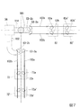
図7は、本実施形態の変形例における基体11に設けられている配線パターンである主接続部の例を示す図である。
図7に示すように、第2の出力部53−2は、第1端子53−2aと第2端子53−2bを備える。第3の出力部53−3は、第1端子53−3aと第2端子53−3bを備える。なお、図7では省略しているが、同様に第1の出力部53−1は、第1端子53−1aと第2端子53−1bを備える。
<Modification>
Next, a modified example of the main connection portion, which is the wiring pattern provided on the base 11, will be described.
FIG. 7 is a diagram showing an example of a main connection portion which is a wiring pattern provided on the base 11 in the modified example of the present embodiment.
As shown in FIG. 7, the second output section 53-2 includes a first terminal 53-2a and a second terminal 53-2b. The third output section 53-3 includes a first terminal 53-3a and a second terminal 53-3b. Although omitted in FIG. 7, similarly, the first output unit 53-1 includes a first terminal 53-1a and a second terminal 53-1b.

また、第3指針駆動用モータユニット7の入力部72は、入力部72a(第3端子)と入力部72b(第4端子)とを備えている。第4指針駆動用モータユニット8の入力部82は、入力部82a(第3端子)と入力部82b(第4端子)とを備えている。なお、図7では省略しているが、同様に第2指針駆動用モータユニット6の入力部62は、入力部62a(第3端子)と入力部62b(第4端子)とを備えている。   The input section 72 of the third pointer driving motor unit 7 includes an input section 72a (third terminal) and an input section 72b (fourth terminal). The input section 82 of the fourth pointer driving motor unit 8 includes an input section 82a (third terminal) and an input section 82b (fourth terminal). Although not shown in FIG. 7, similarly, the input section 62 of the second pointer driving motor unit 6 includes an input section 62a (third terminal) and an input section 62b (fourth terminal).

さらに、図6および図7に示した基体11上の主接続部102は、図7に示すように、主接続部102a(第1主接続部)と主接続部102b(第2主接続部)とを備えている。また、主接続部102aと主接続部102bとは、複数の箇所における間隔が等しい、すなわち平行である。
同様に、入力部52と第3の出力部53−3に接続される基板上の主接続部は、主接続部103a(第1主接続部)と主接続部103b(第2主接続部)とを備えている。また、主接続部103aと主接続部103bとは、複数の箇所における間隔が等しい。
Further, as shown in FIG. 7, the main connecting portion 102 on the base 11 shown in FIGS. 6 and 7 has a main connecting portion 102a (first main connecting portion) and a main connecting portion 102b (second main connecting portion). It has and. Further, the main connecting portion 102a and the main connecting portion 102b have equal intervals at a plurality of locations, that is, they are parallel to each other.
Similarly, the main connecting portions on the substrate connected to the input portion 52 and the third output portion 53-3 are the main connecting portion 103a (first main connecting portion) and the main connecting portion 103b (second main connecting portion). It has and. Further, the main connection portion 103a and the main connection portion 103b have the same intervals at a plurality of locations.

図7に示すように、2つの主接続部(配線パターン)を平行に設けることで、各ユニットを当該平行に設けられている主接続部上に配置することができる。2つの主接続部を平行に設けることで、例えば、入力部を、指針軸501から距離L1の位置(入力部72、入力部82に示す位置)に配置したり、距離L2(L2はL1より大きい)の位置(入力部72’、入力部82’に示す位置)に配置する自由度を得ることができる。これにより、例えば、多機能電子機器1の直径が38mm、42mm等、複数のモデルに対応することができる。   As shown in FIG. 7, by providing two main connecting portions (wiring patterns) in parallel, each unit can be arranged on the main connecting portions provided in parallel. By providing the two main connecting portions in parallel, for example, the input portion is arranged at a position at a distance L1 from the pointer shaft 501 (positions indicated by the input portion 72 and the input portion 82), or at a distance L2 (where L2 is greater than L1). It is possible to obtain the degree of freedom in arranging at the (larger) position (the positions shown in the input unit 72 'and the input unit 82'). Thereby, for example, the multi-function electronic device 1 can correspond to a plurality of models having a diameter of 38 mm, 42 mm, or the like.

また、本実施形態の多機能電子機器1において、第1指針駆動用モータユニット5は、第1端子(出力部53の一方の端子、例えば53−1a、53−2a、53−3a)と、第2端子(出力部53の他方の端子、例えば53−1b、53−2b、53−3b)と、を備え、主接続部(基体11上の配線パターン102、103a,103b)は、第1端子と導通する第1主接続部(例えば主接続部102a、103a)と第2端子と導通する第2主接続部(例えば主接続部102b、103b)とにより構成される。   In the multifunctional electronic device 1 of the present embodiment, the first pointer driving motor unit 5 has the first terminal (one terminal of the output section 53, for example, 53-1a, 53-2a, 53-3a), A second terminal (the other terminal of the output section 53, for example, 53-1b, 53-2b, 53-3b), and the main connection section (the wiring patterns 102, 103a, 103b on the base 11) is the first terminal. It is composed of a first main connecting portion (for example, main connecting portions 102a and 103a) that conducts with the terminal and a second main connecting portion (for example, main connecting portions 102b and 103b) that conducts with the second terminal.

この構成によって、本実施形態では、複数の接続線である基体11上の配線パターンを用いて、第1指針駆動用モータユニットに対してアナログ制御(モータの駆動)を行うことができる。   With this configuration, in the present embodiment, it is possible to perform analog control (driving of the motor) on the first pointer driving motor unit by using the wiring pattern on the base body 11 which is a plurality of connection lines.

また、本実施形態の多機能電子機器1において、第1主接続部(102a、103a)と第2主接続部(102b、103b)とは複数の箇所において互いの間隔が等しい。   Further, in the multifunctional electronic device 1 of the present embodiment, the first main connecting portions (102a, 103a) and the second main connecting portions (102b, 103b) have the same interval at a plurality of points.

この構成によって、本実施形態では、基体11上の配線パターンである主接続部(接続線)のどこにでも、第2指針駆動用モータユニット(第2指針駆動用モータユニット6、第3指針駆動用モータユニット7、第4指針駆動用モータユニット8)を実装できるので、レイアウト自由度が増す。   With this configuration, in the present embodiment, the second pointer driving motor unit (the second pointer driving motor unit 6 and the third pointer driving motor unit 6 is provided anywhere on the main connecting portion (connection line) that is the wiring pattern on the base 11. Since the motor unit 7 and the fourth pointer driving motor unit 8) can be mounted, layout flexibility is increased.

また、本実施形態の多機能電子機器1において、第2指針駆動用モータユニット(例えば第3指針駆動用モータユニット7)は、第3端子(例えば第4の出力端子53−2a)と、第4端子(例えば第4の出力端子53−2b)と、を備え、主接続部(例えば主接続部102)は、少なくとも第3端子と第4端子との一方と導通する第3主接続部(例えば主接続部102aまたは102b)を備える。   In the multi-function electronic device 1 of the present embodiment, the second pointer driving motor unit (for example, the third pointer driving motor unit 7) has the third terminal (for example, the fourth output terminal 53-2a), 4 terminals (for example, the fourth output terminal 53-2b), and the main connection portion (for example, the main connection portion 102) is the third main connection portion (at least one of the third terminal and the fourth terminal) is electrically connected. For example, the main connection part 102a or 102b) is provided.

この構成によって、本実施形態では、モータ数を増やしても、モータ数に応じて端子数を増やせば良いので、第1指針駆動用モータユニット5が他のユニットを制御可能である。   With this configuration, in the present embodiment, even if the number of motors is increased, the number of terminals may be increased according to the number of motors, so that the first pointer driving motor unit 5 can control other units.

なお、本発明における制御部56の機能を実現するためのプログラムをコンピュータ読み取り可能な記録媒体に記録して、この記録媒体に記録されたプログラムをコンピュータシステムに読み込ませ、実行することにより自モジュール内のモータの制御、他モジュールの制御を行ってもよい。なお、ここでいう「コンピュータシステム」とは、OSや周辺機器等のハードウェアを含むものとする。また、「コンピュータシステム」は、ホームページ提供環境(あるいは表示環境)を備えたWWWシステムも含むものとする。また、「コンピュータ読み取り可能な記録媒体」とは、フレキシブルディスク、光磁気ディスク、ROM、CD−ROM等の可搬媒体、コンピュータシステムに内蔵されるハードディスク等の記憶装置のことをいう。さらに「コンピュータ読み取り可能な記録媒体」とは、インターネット等のネットワークや電話回線等の通信回線を介してプログラムが送信された場合のサーバやクライアントとなるコンピュータシステム内部の揮発性メモリ(RAM)のように、一定時間プログラムを保持しているものも含むものとする。   Note that a program for realizing the function of the control unit 56 in the present invention is recorded in a computer-readable recording medium, and the program recorded in this recording medium is read into a computer system and executed to execute the program in its own module. The control of the motor and the control of other modules may be performed. The “computer system” mentioned here includes an OS and hardware such as peripheral devices. Further, the "computer system" also includes a WWW system having a homepage providing environment (or display environment). Further, the “computer-readable recording medium” refers to a portable medium such as a flexible disk, a magneto-optical disk, a ROM, a CD-ROM, or a storage device such as a hard disk built in a computer system. Further, the "computer-readable recording medium" is a volatile memory (RAM) inside a computer system that serves as a server or a client when a program is transmitted via a network such as the Internet or a communication line such as a telephone line. In addition, those that hold the program for a certain period of time are also included.

また、上記プログラムは、このプログラムを記憶装置等に格納したコンピュータシステムから、伝送媒体を介して、あるいは、伝送媒体中の伝送波により他のコンピュータシステムに伝送されてもよい。ここで、プログラムを伝送する「伝送媒体」は、インターネット等のネットワーク(通信網)や電話回線等の通信回線(通信線)のように情報を伝送する機能を有する媒体のことをいう。また、上記プログラムは、前述した機能の一部を実現するためのものであってもよい。さらに、前述した機能をコンピュータシステムにすでに記録されているプログラムとの組み合わせで実現できるもの、いわゆる差分ファイル(差分プログラム)であってもよい。   Further, the program may be transmitted from a computer system that stores the program in a storage device or the like to another computer system via a transmission medium or by a transmission wave in the transmission medium. Here, the "transmission medium" for transmitting the program refers to a medium having a function of transmitting information such as a network (communication network) such as the Internet or a communication line (communication line) such as a telephone line. Further, the program may be for realizing a part of the functions described above. Further, it may be a so-called difference file (difference program) that can realize the above-mentioned functions in combination with a program already recorded in the computer system.

以上、本発明の実施形態について説明したが、本発明は、上記実施形態に限定されるものではなく、本発明の趣旨を逸脱しない範囲において種々の変更を加えることが可能である。
また、用途も種々変更可能である。例えば、内燃機関、モータ等により駆動される車両に搭載されたBLE送受信装置から、運転者等が装着するスマートウォッチ(多機能電子機器)が車速情報、回転数情報、燃料残量情報等を受信し、それら車速、回転数、燃料残量等を表示するためのコマンドをスマートウォッチのマイコン(主制御部)から指針駆動用モータユニットのドライブIC(制御部)に送信することもできる。これにより、指針駆動用モータユニットの指針が車速情報等を表示することができる。また、車載の計器類表示部(インパネ内部等)に、直接、指針駆動用モータユニットを実装することもできる。
Although the embodiment of the present invention has been described above, the present invention is not limited to the above embodiment, and various modifications can be made without departing from the spirit of the present invention.
Further, the usage can be variously changed. For example, a smart watch (multifunctional electronic device) worn by a driver or the like receives vehicle speed information, rotation speed information, fuel remaining amount information, etc. from a BLE transmitter / receiver mounted on a vehicle driven by an internal combustion engine, a motor, etc. However, the command for displaying the vehicle speed, the number of revolutions, the remaining fuel amount, etc. can be transmitted from the microcomputer (main control unit) of the smart watch to the drive IC (control unit) of the pointer driving motor unit. Thereby, the pointer of the pointer driving motor unit can display the vehicle speed information and the like. Further, the pointer driving motor unit can be directly mounted on the instrument display unit (inside the instrument panel, etc.) mounted on the vehicle.

1…多機能電子機器、2…発振回路、3…操作部、4…主制御部、5…第1指針駆動用モータユニット、6…第2指針駆動用モータユニット、7…第3指針駆動用モータユニット、8…第4指針駆動用モータユニット、9…付加ユニット、10…通信部、11…基体、12…ベルト、13…文字盤、51…支持体、52…入力部、53…出力部、54…発振回路、55…記憶部、56…制御部、57…第1のモータ、58…第1指針、61…支持体、62…入力部、67…第2のモータ、68…第2指針、71…支持体、72…入力部、77…第3のモータ、78…第3指針、81…支持体、82…入力部、87…第4のモータ、88…第4指針、91…支持体、92…入力部、99…報知部、101…副接続部、102、103…主接続部、111、112、113…接続部、102a、103a…第1主接続部、102b、103b…第2主接続部 DESCRIPTION OF SYMBOLS 1 ... Multifunctional electronic device, 2 ... Oscillation circuit, 3 ... Operation part, 4 ... Main control part, 5 ... 1st pointer drive motor unit, 6 ... 2nd pointer drive motor unit, 7 ... 3rd pointer drive Motor unit, 8 ... Fourth pointer driving motor unit, 9 ... Additional unit, 10 ... Communication section, 11 ... Base, 12 ... Belt, 13 ... Dial, 51 ... Support, 52 ... Input section, 53 ... Output section , 54 ... Oscillation circuit, 55 ... Storage section, 56 ... Control section, 57 ... First motor, 58 ... First pointer, 61 ... Support, 62 ... Input section, 67 ... Second motor, 68 ... Second Pointer, 71 ... Support, 72 ... Input section, 77 ... Third motor, 78 ... Third pointer, 81 ... Support, 82 ... Input section, 87 ... Fourth motor, 88 ... Fourth pointer, 91 ... Support, 92 ... Input section, 99 ... Notification section, 101 ... Sub connection section, 102, 103 ... Main connection section 111, 112, 113 ... connecting portion, 102a, 103a ... first main connection portion, 102b, 103b ... second main connection unit

Claims (7)

第1ステッピングモータ、前記第1ステッピングモータにより回転される第1指針、および前記第1指針を回転させるように前記第1ステッピングモータを制御する制御部、を備え、基体の中央部に配置される第1指針駆動用モータユニットと
記制御部により制御される第2ステッピングモータ、および前記第2ステッピングモータにより回転される第2指針、を備え、前記基体において、前記中央部を囲う周辺部に配置される第2指針駆動用モータユニットと、
前記基体の前記周辺部に配置される主制御部と、
前記基体において、前記中央部から前記周辺部に向かう方向に配置され、前記第1指針駆動用モータユニットと前記第2指針駆動用モータユニットとを接続する主接続部と、
前記基体において、前記中央部から前記周辺部に向かう方向に配置され、前記主制御部と前記第1指針駆動用モータユニットとを接続する副接続部と、
備え
前記制御部は、前記第1ステッピングモータと前記第2ステッピングモータの少なくとも一つを前記主制御部からの信号により制御す多機能電子機器。
The first stepping motor, a control unit, which controls the first stepping motor to rotate the first guidance to be rotated, and the first pointer by the first stepping motor, disposed in a central portion of the base body a first pointer driving motor unit that will be,
The second stepping motor which is pre-Symbol by Ri control to the control unit, and a second pointer, which is rotated by the second stepping motor in the base, the Ru is disposed on the periphery surrounding said central portion 2 pointer drive motor unit,
A main control unit arranged in the peripheral portion of the base,
A main connecting portion that is arranged in the base body in a direction from the central portion toward the peripheral portion and connects the first pointer driving motor unit and the second pointer driving motor unit;
In the base, a sub connecting portion that is arranged in a direction from the central portion toward the peripheral portion and that connects the main control portion and the first pointer driving motor unit,
Equipped with a,
Wherein the control unit that controls at least one of the second stepping motor and the first stepping motor by a signal from the main controller, multifunction electronic device.
前記第1指針駆動用モータユニットは、第1端子と、第2端子と、を備え、
前記主接続部は、前記第1端子と導通する第1主接続部と前記第2端子と導通する第2主接続部とにより構成される、請求項1に記載の多機能電子機器。
The first pointer driving motor unit includes a first terminal and a second terminal,
The multifunctional electronic device according to claim 1, wherein the main connection portion includes a first main connection portion that is electrically connected to the first terminal and a second main connection portion that is electrically connected to the second terminal.
前記第1主接続部と前記第2主接続部とは、複数の箇所において互いの間隔が等しい、請求項2に記載の多機能電子機器。   The multi-function electronic device according to claim 2, wherein the first main connection portion and the second main connection portion have equal intervals at a plurality of locations. 前記第2指針駆動用モータユニットは、第3端子と、第4端子と、を備え、
前記主接続部は、少なくとも前記第3端子と前記第4端子との一方と導通する第3主接続部を備える、請求項1から請求項のいずれか1項に記載の多機能電子機器。
The second pointer driving motor unit includes a third terminal and a fourth terminal,
It said main connection portion is provided with a third main connection portion to conduct at least the third terminal and one of said fourth terminals, multi-function electronic device according to any one of claims 1 to 3.
前記第1指針駆動用モータユニットと接続される第3指針駆動用モータユニット、を備え、
前記第3指針駆動用モータユニットは、第3指針と、前記制御部により前記第3指針を回転させるように制御される第3ステッピングモータと、を備える、請求項1から請求項のいずれか1項に記載の多機能電子機器。
A third pointer driving motor unit connected to the first pointer driving motor unit,
The third pointer driving motor unit includes a third pointer, and a third stepping motor controlled to rotate the third pointer by the control unit, one of claims 1 to 4 The multifunctional electronic device according to item 1.
前記第1指針駆動用モータユニットは、前記副接続部が接続される入力部と、前記第2指針駆動用モータユニットが接続される出力部とを備え、
前記入力部と前記出力部とは、前記第1指針を中心として30度以上180度以下離間して配置される、請求項に記載の多機能電子機器。
The first pointer driving motor unit includes an input section to which the sub connecting section is connected, and an output section to which the second pointer driving motor unit is connected,
The multi-function electronic device according to claim 1 , wherein the input unit and the output unit are arranged apart from each other by 30 degrees or more and 180 degrees or less around the first pointer.
外部から視認可能な面を有する文字盤、を備え、
前記基体は前記文字盤に対して固定され、前記第1指針駆動用モータユニットは前記文字盤の中央部に配置され、前記第2指針駆動用モータユニットと前記主制御部とは前記文字盤において、前記中央部を囲う周辺部に配置される、請求項に記載の多機能電子機器。
Equipped with a dial having a surface visible from the outside,
The base is fixed to the dial, the first pointer driving motor unit is arranged in the center of the dial, and the second pointer driving motor unit and the main control unit are arranged in the dial . The multifunctional electronic device according to claim 1 , wherein the multifunctional electronic device is arranged in a peripheral portion surrounding the central portion .
JP2016000686A 2016-01-05 2016-01-05 Multifunction electronic device Active JP6694271B2 (en)

Priority Applications (1)

Application Number Priority Date Filing Date Title
JP2016000686A JP6694271B2 (en) 2016-01-05 2016-01-05 Multifunction electronic device

Applications Claiming Priority (1)

Application Number Priority Date Filing Date Title
JP2016000686A JP6694271B2 (en) 2016-01-05 2016-01-05 Multifunction electronic device

Publications (2)

Publication Number Publication Date
JP2017122605A JP2017122605A (en) 2017-07-13
JP6694271B2 true JP6694271B2 (en) 2020-05-13

Family

ID=59306587

Family Applications (1)

Application Number Title Priority Date Filing Date
JP2016000686A Active JP6694271B2 (en) 2016-01-05 2016-01-05 Multifunction electronic device

Country Status (1)

Country Link
JP (1) JP6694271B2 (en)

Also Published As

Publication number Publication date
JP2017122605A (en) 2017-07-13

Similar Documents

Publication Publication Date Title
JP5878852B2 (en) Electronic clock authentication method and electronic clock for implementing the method
TWI596454B (en) Wrest Watch Wireless Control Module and Method for Communication of the Wrest Watch
GB1572513A (en) Quartz crystal controlled analogue timepiece
JP6694270B2 (en) Pointer drive motor unit and control method for pointer drive motor unit
JP6694271B2 (en) Multifunction electronic device
JP6459593B2 (en) Antenna device and electronic timepiece
JP2006343240A (en) Timepiece movement and timepiece
JPH05281370A (en) Analog electronic timepiece
JP6652809B2 (en) Electronic clock, electronic clock system, and electronic clock control method
JP6774298B2 (en) How to control the pointer drive motor unit, electronic equipment, and pointer drive motor unit
JP6961463B2 (en) Ringing mechanism, mobile devices, movements and watches
JP3266917B2 (en) Multifunction electronic clock
US10831158B2 (en) Timepiece, motor control device, control method of timepiece, and motor control method
JP2993201B2 (en) Mode display structure of multifunction electronic watch
WO2001055801A1 (en) Electronic timepiece having indication hands
JPH0719903A (en) Small-sized analog display device
JPS6116545Y2 (en)
JPH0617115Y2 (en) Watch movement with circuit board
JPH0453596Y2 (en)
JP3631381B2 (en) Compound display electronic clock
JP2001133564A (en) Electronic device
JP2992465B2 (en) Alarm clock
JPS6314312B2 (en)
JPS6015191Y2 (en) electronic clock
JPH0419514Y2 (en)

Legal Events

Date Code Title Description
RD04 Notification of resignation of power of attorney

Free format text: JAPANESE INTERMEDIATE CODE: A7424

Effective date: 20170913

A621 Written request for application examination

Free format text: JAPANESE INTERMEDIATE CODE: A621

Effective date: 20181108

A977 Report on retrieval

Free format text: JAPANESE INTERMEDIATE CODE: A971007

Effective date: 20191025

A131 Notification of reasons for refusal

Free format text: JAPANESE INTERMEDIATE CODE: A131

Effective date: 20191119

A521 Request for written amendment filed

Free format text: JAPANESE INTERMEDIATE CODE: A523

Effective date: 20200108

TRDD Decision of grant or rejection written
A01 Written decision to grant a patent or to grant a registration (utility model)

Free format text: JAPANESE INTERMEDIATE CODE: A01

Effective date: 20200407

A61 First payment of annual fees (during grant procedure)

Free format text: JAPANESE INTERMEDIATE CODE: A61

Effective date: 20200417

R150 Certificate of patent or registration of utility model

Ref document number: 6694271

Country of ref document: JP

Free format text: JAPANESE INTERMEDIATE CODE: R150

R250 Receipt of annual fees

Free format text: JAPANESE INTERMEDIATE CODE: R250

R250 Receipt of annual fees

Free format text: JAPANESE INTERMEDIATE CODE: R250