JP6693204B2 - Image forming device - Google Patents
Image forming device Download PDFInfo
- Publication number
- JP6693204B2 JP6693204B2 JP2016057473A JP2016057473A JP6693204B2 JP 6693204 B2 JP6693204 B2 JP 6693204B2 JP 2016057473 A JP2016057473 A JP 2016057473A JP 2016057473 A JP2016057473 A JP 2016057473A JP 6693204 B2 JP6693204 B2 JP 6693204B2
- Authority
- JP
- Japan
- Prior art keywords
- opening
- exposure
- housing
- closing
- image forming
- Prior art date
- Legal status (The legal status is an assumption and is not a legal conclusion. Google has not performed a legal analysis and makes no representation as to the accuracy of the status listed.)
- Active
Links
- 238000000034 method Methods 0.000 claims description 3
- 239000002184 metal Substances 0.000 description 31
- 230000007246 mechanism Effects 0.000 description 11
- 230000032258 transport Effects 0.000 description 11
- 125000002066 L-histidyl group Chemical group [H]N1C([H])=NC(C([H])([H])[C@](C(=O)[*])([H])N([H])[H])=C1[H] 0.000 description 4
- 238000005452 bending Methods 0.000 description 3
- 238000010586 diagram Methods 0.000 description 3
- 230000000694 effects Effects 0.000 description 3
- 230000005611 electricity Effects 0.000 description 2
- 230000003068 static effect Effects 0.000 description 2
- QVGXLLKOCUKJST-UHFFFAOYSA-N atomic oxygen Chemical compound [O] QVGXLLKOCUKJST-UHFFFAOYSA-N 0.000 description 1
- 229910052760 oxygen Inorganic materials 0.000 description 1
- 239000001301 oxygen Substances 0.000 description 1
- 230000003014 reinforcing effect Effects 0.000 description 1
- 239000011347 resin Substances 0.000 description 1
- 229920005989 resin Polymers 0.000 description 1
- 239000002023 wood Substances 0.000 description 1
Images


Classifications
-
- G—PHYSICS
- G03—PHOTOGRAPHY; CINEMATOGRAPHY; ANALOGOUS TECHNIQUES USING WAVES OTHER THAN OPTICAL WAVES; ELECTROGRAPHY; HOLOGRAPHY
- G03G—ELECTROGRAPHY; ELECTROPHOTOGRAPHY; MAGNETOGRAPHY
- G03G21/00—Arrangements not provided for by groups G03G13/00 - G03G19/00, e.g. cleaning, elimination of residual charge
- G03G21/16—Mechanical means for facilitating the maintenance of the apparatus, e.g. modular arrangements
- G03G21/1604—Arrangement or disposition of the entire apparatus
- G03G21/1623—Means to access the interior of the apparatus
- G03G21/1633—Means to access the interior of the apparatus using doors or covers
-
- G—PHYSICS
- G03—PHOTOGRAPHY; CINEMATOGRAPHY; ANALOGOUS TECHNIQUES USING WAVES OTHER THAN OPTICAL WAVES; ELECTROGRAPHY; HOLOGRAPHY
- G03G—ELECTROGRAPHY; ELECTROPHOTOGRAPHY; MAGNETOGRAPHY
- G03G21/00—Arrangements not provided for by groups G03G13/00 - G03G19/00, e.g. cleaning, elimination of residual charge
- G03G21/16—Mechanical means for facilitating the maintenance of the apparatus, e.g. modular arrangements
- G03G21/1604—Arrangement or disposition of the entire apparatus
- G03G21/1623—Means to access the interior of the apparatus
- G03G21/1628—Clamshell type
-
- G—PHYSICS
- G03—PHOTOGRAPHY; CINEMATOGRAPHY; ANALOGOUS TECHNIQUES USING WAVES OTHER THAN OPTICAL WAVES; ELECTROGRAPHY; HOLOGRAPHY
- G03G—ELECTROGRAPHY; ELECTROPHOTOGRAPHY; MAGNETOGRAPHY
- G03G21/00—Arrangements not provided for by groups G03G13/00 - G03G19/00, e.g. cleaning, elimination of residual charge
- G03G21/16—Mechanical means for facilitating the maintenance of the apparatus, e.g. modular arrangements
- G03G21/1604—Arrangement or disposition of the entire apparatus
- G03G21/1623—Means to access the interior of the apparatus
-
- G—PHYSICS
- G03—PHOTOGRAPHY; CINEMATOGRAPHY; ANALOGOUS TECHNIQUES USING WAVES OTHER THAN OPTICAL WAVES; ELECTROGRAPHY; HOLOGRAPHY
- G03G—ELECTROGRAPHY; ELECTROPHOTOGRAPHY; MAGNETOGRAPHY
- G03G21/00—Arrangements not provided for by groups G03G13/00 - G03G19/00, e.g. cleaning, elimination of residual charge
- G03G21/16—Mechanical means for facilitating the maintenance of the apparatus, e.g. modular arrangements
- G03G21/1661—Mechanical means for facilitating the maintenance of the apparatus, e.g. modular arrangements means for handling parts of the apparatus in the apparatus
- G03G21/1666—Mechanical means for facilitating the maintenance of the apparatus, e.g. modular arrangements means for handling parts of the apparatus in the apparatus for the exposure unit
Description
本発明は、画像形成装置に関する。 The present invention relates to an image forming apparatus.
特許文献1に記載の画像形成装置では、カートリッジカバー(開閉部材)を閉じたときに、接続手段の接点部が記憶手段の接点部に接触するようになっている。 In the image forming apparatus described in Patent Document 1, the contact portion of the connection means comes into contact with the contact portion of the storage means when the cartridge cover (opening / closing member) is closed.
筐体の開口部を開閉する開閉部材の開閉動作に伴って露光部材が移動する構成がある。この構成では、開閉部材が筐体の開口部を閉止する閉止位置で、露光部材は、像保持体と対向する対向位置に配置される。これに対して、開閉部材が筐体の開口部を開放する開放位置で、露光部材は、像保持体から退避する退避位置に配置される。また、露光部材が対向位置又は退避位置に配置されている状態で、露光部材は接地されているが、露光部材が対向位置から退避位置へ移動している過程で、露光部材の接地は考慮されていなかった。 There is a configuration in which the exposure member moves in accordance with the opening / closing operation of the opening / closing member that opens / closes the opening of the housing. In this configuration, the opening / closing member is located at the closed position where it closes the opening of the housing, and the exposure member is located at a position facing the image carrier. On the other hand, at the open position where the opening / closing member opens the opening of the housing, the exposure member is arranged at the retracted position where it is retracted from the image carrier. Further, although the exposure member is grounded in a state where the exposure member is arranged at the facing position or the retracted position, the grounding of the exposure member is considered when the exposure member is moving from the facing position to the retracted position. I didn't.
そして、開閉部材が半開きの状態で、ユーザが開口部から手を筐体の内部に手を入れて接地されていない露光部材に触れてしまうと、ユーザにたまった電荷が静電気として露光部材に流れ、露光部材が破損してしまうことがあった。 Then, if the user puts his / her hand inside the housing through the opening and touches an ungrounded exposure member with the opening / closing member half-opened, the charge accumulated on the user flows to the exposure member as static electricity. However, the exposed member may be damaged.
本発明の課題は、開閉部材が半開きの状態で露光部材が接地されていない場合と比して、開閉部材が半開きの状態でユーザが筐体の内部に手を入れて露光部材に触れても露光部材が破損するのを抑制することである。 The problem to be solved by the present invention is that even when the user puts his / her hand inside the housing and touches the exposure member with the opening / closing member in the half-opened state, as compared to the case where the opening / closing member is in the half-opened state and the exposure member is not grounded It is to suppress the damage of the exposure member.
本発明の第1態様に係る画像形成装置は、回転して筐体の開口部を開閉する開閉部材と、前記筐体の内部に配置される像保持体と、前記筐体の内部に配置され、前記開閉部材の開閉動作に伴って移動し、前記開閉部材が前記筐体の前記開口部を閉止する閉止位置で、前記像保持体と対向する対向位置に配置され、前記開閉部材が前記筐体の前記開口部を開放する開放位置で、前記像保持体から退避する退避位置に配置され、対向位置に配置された状態で前記像保持体を露光して静電潜像を形成する露光部材と、静電潜像を現像する現像部材と、少なくとも前記露光部材が対向位置から退避位置へ移動している過程で、前記露光部材を接地する接地部材と、を備えることを特徴とする。 An image forming apparatus according to a first aspect of the present invention includes an opening / closing member that rotates to open and close an opening of a housing, an image carrier arranged inside the housing, and an image holding body arranged inside the housing. The opening / closing member moves in accordance with the opening / closing operation of the opening / closing member, and the opening / closing member is arranged at a facing position facing the image carrier at a closing position where the opening / closing member closes the opening of the housing. An exposure member that is located at a retracted position that retracts from the image carrier at an open position that opens the opening of the body and that exposes the image carrier in a state of being disposed at a facing position to form an electrostatic latent image. A developing member for developing the electrostatic latent image, and a grounding member for grounding the exposing member at least while the exposing member is moving from the facing position to the retracted position.
本発明の第2態様に係る画像形成装置は、回転して筐体の開口部を開閉する開閉部材と、前記筐体の内部に配置される像保持体と、前記筐体の内部に配置され、前記開閉部材の開閉動作に伴って移動し、前記開閉部材が前記筐体の前記開口部を閉止する閉止位置で、前記像保持体と対向する対向位置に配置され、前記開閉部材が前記筐体の前記開口部を開放する開放位置で、前記像保持体から退避する退避位置に配置され、対向位置に配置された状態で前記像保持体を露光して静電潜像を形成する露光部材と、静電潜像を現像する現像部材と、少なくとも対向位置と退避位置との間の位置に配置されている前記露光部材を接地する接地部材と、を備えることを特徴とする。
本発明の第3態様に係る画像形成装置は、第1態様又は第2態様に記載の画像形成装置において、前記接地部材は、前記露光部材が対向位置に配置されている状態でも前記露光部材を接地し、前記接地部材は、前記露光部材に取り付けられた板状の第一部材と、前記筐体に取り付けられ、接地されている板状の第二部材と、前記筐体に取り付けられ、接地されているコイル状の伸縮部材と、を有し、前記露光部材が対向位置に配置されている状態で、前記第一部材と前記第二部材とが接触し、かつ、前記第一部材と前記伸縮部材とが離間し、前記露光部材が対向位置から退避位置へ移動している過程では、前記露光部材の移動に伴って前記第一部材と前記第二部材とが離間し、かつ、前記第一部材と前記第二部材とが離間する前に、前記露光部材の移動に伴って前記第一部材と前記伸縮部材とが接触していることを特徴とする。
An image forming apparatus according to a second aspect of the present invention includes an opening / closing member that rotates to open / close an opening of a housing, an image holding body arranged inside the housing, and an image holding body arranged inside the housing. The opening / closing member moves in accordance with the opening / closing operation of the opening / closing member, and the opening / closing member is arranged at a facing position facing the image carrier at a closing position where the opening / closing member closes the opening of the housing. An exposure member that is located at a retracted position that retracts from the image carrier at an open position that opens the opening of the body and that exposes the image carrier in a state of being disposed at a facing position to form an electrostatic latent image. And a developing member that develops the electrostatic latent image, and a grounding member that grounds the exposure member that is disposed at least between the facing position and the retracted position.
An image forming apparatus according to a third aspect of the present invention is the image forming apparatus according to the first aspect or the second aspect , wherein the grounding member is provided with the exposure member even when the exposure member is arranged at a facing position. The grounding member is grounded, and the grounding member is a plate-shaped first member mounted on the exposure member, a plate-shaped second member mounted on the housing and grounded, and a grounded member mounted on the housing. A coil-shaped stretchable member, and the first member and the second member are in contact with each other in a state where the exposure member is arranged at a facing position, and the first member and the In the process in which the elastic member is separated and the exposure member is moving from the facing position to the retracted position, the first member and the second member are separated as the exposure member moves, and The exposure is performed before one member and the second member are separated from each other. Characterized in that said elastic member and the first member with the movement of the wood is in contact.
本発明の第1態様又は第2態様の画像形成装置によれば、開閉部材が半開きの状態で露光部材が接地されていない場合と比して、開閉部材が半開きの状態でユーザが筐体の内部に手を入れて露光部材に触れても露光部材が破損するのを抑制することができる。 According to the image forming apparatus of the first aspect or the second aspect of the present invention, as compared with the case where the exposure member is not grounded when the opening / closing member is in the half-opened state, the user can operate the housing with the opening / closing member in the half-opened state. It is possible to prevent the exposure member from being damaged even if a hand is put inside and the exposure member is touched.
本発明の第3形態の画像形成装置によれば、露光部材が対向位置に配置されている状態で、第一部材と伸縮部材とが接触している場合と比して、露光部材が稼動している最中に、アンテナ効果によって露光部材にノイズが発生するのを抑制することができる。 According to the image forming apparatus of the third aspect of the present invention, the exposure member operates in the state where the exposure member is arranged at the facing position, as compared with the case where the first member and the elastic member are in contact with each other. It is possible to suppress the generation of noise on the exposure member due to the antenna effect during the operation.
本発明の実施形態に係る画像形成装置の一例を図1〜図12に従って説明する。なお、図中に示す矢印Hは装置上下方向(鉛直方向)を示し、矢印Wは装置幅方向(水平方向)を示し、矢印Dは装置奥行方向(水平方向)を示す。 An example of the image forming apparatus according to the embodiment of the present invention will be described with reference to FIGS. An arrow H shown in the drawing indicates the vertical direction of the apparatus (vertical direction), an arrow W indicates the width direction of the apparatus (horizontal direction), and an arrow D indicates the depth direction of the apparatus (horizontal direction).
(全体構成)
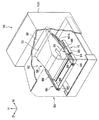
図1に示されるように、本実施形態に係る画像形成装置10には、上下方向(矢印H方向)の下方から上方へ向けて、記録媒体としての用紙Pが収容される収容部14と、収容部14に収容された用紙Pを搬送する搬送部16と、収容部14から搬送部16によって搬送される用紙Pに画像形成を行う画像形成部20とが、この順で備えられている。
(overall structure)
As shown in FIG. 1, the
〔収容部〕
収容部14には、画像形成装置10の筐体10Aから装置奥行方向の手前側に引き出し可能な収容部材26が備えられており、この収容部材26に用紙Pが積載されている。さらに、収容部14には、収容部材26に積載された用紙Pを、搬送部16を構成する搬送経路28に送り出す送出ロール30が備えられている。
[Housing]
The
〔搬送部〕
搬送部16には、搬送経路28に沿って用紙Pを搬送する複数の搬送ロール32が備えられている。
[Transportation part]
The
〔画像形成部〕
画像形成部20には、装置本体に対して脱着可能で、黒色のトナー画像を形成する画像形成部の一例としての画像形成ユニット18と、露光光を後述する像保持体36に照射する露光部材の一例としての露光ユニット42とが備えられている。さらに、画像形成部20には、画像形成ユニット18によって形成されたトナー画像を用紙Pに転写する転写ロール44と、熱と圧力とでトナー画像を用紙Pに定着する定着装置46とが備えられている。
[Image forming section]
The
この画像形成ユニット18には、像保持体36と、像保持体36の表面を帯電させる帯電ロール38と、露光ユニット42によって露光光が照射されて像保持体36に形成された静電潜像を現像してトナー画像として可視化する現像装置40とが備えられている。
The
ここで、画像形成ユニット18には、現像装置40を含む下方部18Aと、帯電ロール38を含む上方部18Bとが備えられている。また、下方部18Aと上方部18Bとは、装置奥行方向の両端部で連結され、下方部18Aと上方部18Bとの間には隙間18Cが形成されている。この隙間18Cに、露光ユニット42の一部が配置されている。
Here, the
そして、画像形成ユニット18を図中矢印A方向に移動させることで、画像形成ユニット18を筐体10Aに対し脱着できるようになっている。
By moving the
なお、露光ユニット42を接地させる接地部材68、及び露光ユニット42については詳細を後述する。
The
〔その他〕
画像形成装置10には、筐体10Aの開口部62を開閉し、開口部62を開放した状態で画像形成ユニット18を脱着可能とする開閉部材の一例としての開閉カバー54と、開閉カバー54の開閉動作に伴って露光ユニット42を移動させるためのリンク機構86とが備えられている。なお、開閉カバー54、及びリンク機構86については、詳細を後述する。
[Other]
In the
(画像形成装置の作用)
画像形成装置10では、次のようにして画像が形成される。
(Operation of image forming apparatus)
In the
先ず、電圧が印加された帯電ロール38は、像保持体36の表面を予定の電位で一様にマイナス帯電する。続いて、外部から入力されたデータに基づいて露光ユニット42は、帯電した像保持体36の表面に露光光を照射して静電潜像を形成する。
First, the charging
これにより、データに対応した静電潜像が像保持体36の表面に形成される。さらに、現像装置40は、この静電潜像を現像し、トナー画像として可視化する。
As a result, an electrostatic latent image corresponding to the data is formed on the surface of the
そこで、収容部材26から送出ロール30によって搬送経路28へ送り出された用紙Pは、像保持体36と転写ロール44とが接触する転写位置Tへ送り出される。像保持体36と転写ロール44とが接触する転写位置Tでは、用紙Pが像保持体36と転写ロール44とによって挟持搬送されることで、像保持体36の表面のトナー画像は、用紙Pに転写される。
Then, the paper P sent from the
用紙Pに転写されたトナー画像は、定着装置46によって用紙Pに定着される。そして、トナー画像が定着した用紙Pは、搬送ロール32によって筐体10Aの外部へ排出される。
The toner image transferred onto the sheet P is fixed onto the sheet P by the fixing
(要部構成)
次に、露光ユニット42、接地部材68、開閉カバー54、及びリンク機構86について説明する。
(Main composition)
Next, the
〔露光ユニット〕
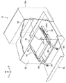
図1に示されるように、露光ユニット42は、像保持体36に対して装置幅方向の一方側(後述する開閉カバー54側)に配置されている。そして、像保持体36に表面に静電潜像を形成可能な対向位置(図1参照)と、像保持体36から退避して画像形成ユニット18に形成された隙間18Cから抜け出る退避位置(図3参照)との間を移動するようになっている。
[Exposure unit]
As shown in FIG. 1, the
この露光ユニット42は、装置奥行方向に並べられた複数の発光素子を備えたLEDプリントヘッド50(以下「ヘッド50」)と、ヘッド50を支持する支持部材56とを備えている。
The
[ヘッド]
図12に示されるように、ヘッド50は、装置奥行方向に延びる断面矩形状で金属製の筐体52を備えている。そして、露光ユニット42が対向位置に配置された状態で、筐体52において像保持体36と対向する対向面52Aから露光光が出射するようになっている。
[head]
As shown in FIG. 12, the
[支持部材]
支持部材56は、樹脂製で、ヘッド50を挟んで像保持体36の反対側(後述するか開閉カバー54側)に配置され、装置幅方向に延びている。支持部材56には、装置奥行方向から見て屈曲する屈曲部56Aと、屈曲部56Aに対して像保持体36側の一方部56Bと、屈曲部56Aを挟んで像保持体36とは反対側の他方部56Cとが形成されている。
[Supporting member]
The
そして、露光ユニット42が対向位置に配置された状態で、装置奥行方向から見て、一方部56Bは、屈曲部56Aから上方に向かうように傾斜して延び、他方部56Cは、装置幅方向に延びている。
When the
さらに、支持部材56には、装置奥行方向の手前側を向いた端面58Aと、装置奥行方向の奥側を向いた端面58Bとが形成されている。また、端面58Aには、装置幅方向に延びるガイド溝60Aがリブを用いて形成され、端面58Bには、装置幅方向に延びるガイド溝60Bがリブを用いて形成されている。
Further, the
そして、基端部が図示せぬ補強部材に取り付けられた複数のガイドピン(図示省略)の先端部が、このガイド溝60A、60Bに装置奥行方向の外側から挿入されている。さらに、支持部材56には、後述するコイルバネ80の他端部80Bが載せされるリブ76が形成されている(図11参照)。
The tip ends of a plurality of guide pins (not shown) whose base ends are attached to a reinforcing member (not shown) are inserted into the
この構成において、露光ユニット42は、ガイド溝60A、60Bに先端部が挿入されたガイドピンに案内されて、対向位置と退避位置との間を移動するようになっている。
In this structure, the
〔接地部材〕
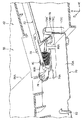
図4に示されるように、接地部材68は、筐体10A(図1参照)に取り付けられ、接地されているフレーム部材70と、フレーム部材70に一端が固定されているコイル状の伸縮部材の一例としてのコイルバネ80と、露光ユニット42の支持部材56に取り付けられている第一板金部材72、及び第二板金部材74とを備えている。第一板金部材72、及び第二板金部材74は、第一部材の一例とされ、フレーム部材70は、第二部材の一例とされている。
[Grounding member]
As shown in FIG. 4, the grounding
[フレーム部材]
フレーム部材70は、金属板を折り曲げて形成されている。そして、図4、図12に示されるように、フレーム部材70は、板面が装置上下方向を向き、上方から見て装置奥行方向に延びる矩形状の本体部70Aと、本体部70Aの装置奥行方向の両端部から上方に突出し、板面が装置奥行方向を向いた一対のフランジ部70Bとを有している。さらに、フレーム部材70は、本体部70Aの装置幅方向の両端部から上方に突出し、板面が装置幅方向を向いた一対のフランジ部70Cを有している。
[Frame member]
The
また、図4に示されるように、本体部70Aにおいて装置幅方向の中央側で、かつ、装置奥行方向の手前側(図中右側)の部分には、上方に切り起され、板面が装置幅方向を向いた切り起し部82が形成されている。
In addition, as shown in FIG. 4, in the
さらに、図4、図9に示されるように、像保持体36側に配置されたフランジ部70Cには、L字状の引掛け部70Dが形成されている。
Further, as shown in FIGS. 4 and 9, an L-shaped hooking
[コイルバネ]
コイルバネ80は、装置幅方向に延びる金属製の引張バネであり、コイルバネ80の一端部80Aは、図9に示されるように、環状とされ、フレーム部材70の引掛け部70Dに引っ掛けられている。
[Coil spring]
The
さらに、コイルバネ80の他端部80Bは、環状とされ、露光ユニット42が対向位置に配置されている状態で、露光ユニット42の支持部材56に形成されたリブ76に載せられている。
Further, the
[第一板金部材・第二板金部材]
第一板金部材72は、金属板を用いて形成され、支持部材56の下方を向いた下面に固定され、図4に示されるように、一端がヘッド50の筐体52に接触し、他端が支持部材56の屈曲部56A側に延びている。さらに、第二板金部材74は、金属板を用いて形成され、支持部材56の下方を向いた下面に固定され、一端が第一板金部材72の他端側の部分に固定され、他端がヘッド50から遠ざかるように延びている。
[First sheet metal member / second sheet metal member]
The first
第一板金部材72の他端側の部分には、露光ユニット42が対向位置に配置されている状態で、像保持体36側のフランジ部70Cに接触する接触部78が形成されている。具体的には、図9に示されるように、接触部78は、第一板金部材72の他端側の部分を折り曲げて形成され、下方へ延びて下端がフランジ部70Cと接触する基部78Aを有している。さらに、接触部78は、基部78Aの下端からフランジ部70Cから遠ざかるように装置幅方向に延びる延設部78Bと、延設部78Bの端部から上方に延びる先端部78Cとを有している。
A
そして、接触部78がフランジ部70Cと接触している状態で、接触部78は、フランジ板に押されて、基部78Aの端部が撓んだ状態となっている。
Then, in the state where the
また、第二板金部材74の一端側の部分は、装置奥行方向の手前側に屈曲しており、この屈曲した部分が、第一板金部材72の下面と接触している。さらに、第二板金部材74の他端側の部分は、装置奥行方向の奥側に屈曲し、装置奥行方向の奥側に延びる延設部74Aが形成されている。そして、露光ユニット42が対向位置に配置されている状態で、この延設部74Aは、コイルバネ80の他端部80Bと非接触を保ってコイルバネ80の他端部80Bを貫通している。
Further, a portion on one end side of the second
この構成において、露光ユニット42が対向位置に配置されている状態で、第一板金部材72の接触部78がフランジ部70Cと接触し、露光ユニット42は、接地されるようになっている。なお、露光ユニット42の移動に伴う接地状態の変化については、後述する作用と共に説明する。
In this configuration, the
〔開閉カバー〕
図8に示されるように、筐体10Aにおいて、露光ユニット42を挟んで像保持体36の反対側の部分には、装置幅方向から見て矩形状の開口部62が形成されている。開閉カバー54は、図1、図3に示されるように、回転して開口部62を閉止する閉止位置(図1参照)と、開口部62を開放する開放位置(図3参照)とに配置されるようになっている。
[Open / close cover]
As shown in FIG. 8, in the
具体的には、開閉カバー54が閉止位置に配置されている状態で、開閉カバー54は、板面が装置幅方向を向いた本体部54Aと、本体部54Aの上端部から装置内部側に湾曲する湾曲部54Bとを有している。さらに、開閉カバー54の下端部に、軸方向が装置奥行方向とされた軸部54Cが形成されている。
Specifically, in the state where the open /
この構成において、図1に示す閉止位置に配置されている開閉カバー54を軸部54C周りに回転させると、開閉カバー54は、図示せぬストッパーによって停止し、図3に示す開放位置に配置されて開口部62を開放するようになっている。そして、図3に示されるように、開口部62が開放されると、矢印A方向に移動する画像形成ユニット18の移動経路が確保されるようになっている。
In this configuration, when the open /
一方、開閉カバー54の本体部54Aには、後述するリンク機構86の端部が取り付けられている取付部64が、装置奥行方向において間隔を空けて2個形成されている(図12参照)。
On the other hand, in the
〔リンク機構〕
リンク機構86は、開閉カバー54の開閉動作に伴って露光ユニット42を移動させるための部材であって、図12に示されるように、装置奥行方向において、露光ユニット42を挟むように2個設けられている。
[Link mechanism]
The
夫々のリンク機構86は、基端部が取付部64に回転可能に取り付けられる第一アーム88と、先端部が露光ユニット42の端面58A、58Bに回転可能に取り付けられ、基端部が第一アーム88の先端部と回転可能に取り付けられる第二アーム90とを備えている。
In each
具体的には、第一アーム88の基端部は、軸方向が装置奥行方向とされた軸部材92を介して取付部64に回転可能に取り付けられている。さらに、第一アーム88の先端部には、装置奥行方向の外側(露光ユニット42とは反対側)に延びる円柱状のピン94が取り付けられている。
Specifically, the base end portion of the
また、支持部材56の端面58A、58Bには、装置奥行方向の外側に延びる円柱状の軸66が形成されている。そして、第二アーム90の先端部は、軸66を介して支持部材56に回転可能に取り付けられている。さらに、第二アーム90の基端部には、第二アーム90の長手方向に延びる長孔90Bが形成され、前述したピン94は、この長孔90Bを貫通し、長孔90B内を移動可能に配置されている。
A
この構成において、開閉カバー54が閉止位置に配置されている状態で、図1に示されるように、ピン94は、長孔90Bの一方側(軸66側)に配置され、露光ユニット42は対向位置に配置されるようになっている。これに対して、開閉カバー54が開放位置に配置されている状態で、図3に示されるように、ピン94は、長孔90Bの他方側に配置され、露光ユニット42は退避位置に配置されるようになっている。
In this configuration, with the opening /
なお、開閉カバー54の開閉動作に伴う露光ユニット42の移動については、後述する作用と共に説明する。
The movement of the
(要部構成の作用)
次に、閉止位置に配置されている開閉カバー54を操作して開放位置に配置する動作等について説明する。
(Operation of essential parts)
Next, the operation of operating the open /
開閉カバー54が閉止位置に配置されている状態で、図1、図4、図7に示されるように、露光ユニット42は対向位置に配置され、露光ユニット42の一部は、画像形成ユニット18に形成された隙間18Cに配置されている。
With the open /
さらに、図9に示されるように、接触部78の基部78Aが撓んだ状態で、第一板金部材72の接触部78は、フランジ部70Cと接触している。このようにして、露光ユニット42は、接地されている。なお、コイルバネ80の他端部80Bは、リブ76に載せられ、第二板金部材74の延設部74Aと離間している。
Further, as shown in FIG. 9, the
この状態で、ユーザが図示せぬ把持部を把持して、開閉カバー54を軸部54C周りに回転させる。そうすると、図2に示されるように、開口部62が、上方側の部分から開放されると共に、リンク機構86のピン94が長孔90Bの他方側に移動する。そして、リンク機構86は、第一アーム88及び第二アーム90を介して開閉カバー54の回転力を露光ユニット42に伝達する。
In this state, the user grips a gripping part (not shown) and rotates the opening /
開閉カバー54の回転力が伝達された露光ユニット42は、ガイド溝60A、60B(図12参照)に先端部が挿入される図示せぬガイドピンに案内されて、対向位置から退避位置に向けて移動する。これにより、露光ユニット42は、画像形成ユニット18に形成された隙間18Cから抜け出ようとする。
The
露光ユニット42が対向位置から退避位置へ移動している過程で、図5、図10に示されるように、第一板金部材72の接触部78は、フランジ部70Cと離間し、コイルバネ80の他端部80Bは、第二板金部材74の延設部74Aと接触している。ここで、コイルバネ80の他端部80Bが、第二板金部材74の延設部74Aと接触するまでの間は、接触部78の基部78Aの撓み代によって、接触部78とフランジ部70Cとの接触状態は、維持されている。このようにして、露光ユニット42は、接地されている。
While the
さらに、開閉カバー54を回転させると、開閉カバー54は、図示せぬストッパーに当たって停止し、図3、図6、図8に示されるように、開放位置に配置され、開口部62が開放される。また、リンク機構86が、開閉カバー54の回転力を露光ユニット42に伝達することで、露光ユニット42は、ガイド溝60A、60B(図12酸素湯)に先端部が挿入される図示せぬガイドピンに案内されて移動し、退避位置に配置される。これにより、露光ユニット42は、画像形成ユニット18に形成された隙間18Cから抜け出る。
When the open /
露光ユニット42が退避位置に配置された状態で、図11に示されるように、コイルバネ80の他端部80Bは、第二板金部材74の延設部74Aと接触している。また、第一板金部材72の接触部78は、接触部78の基部78Aが撓んだ状態で、切り起し部82と接触している。このようにして、露光ユニット42は、接地されている。
With the
この状態で、図3に示されるように、画像形成ユニット18の移動経路が確保されるため、ユーザが開口部62から手を入れ、画像形成ユニット18を矢印A方向に移動することで、画像形成ユニット18が脱着される。
In this state, as shown in FIG. 3, since the movement path of the
なお、開放位置の開閉カバー54を閉止位置に配置する場合には、開放位置に配置されている開閉カバー54を閉止位置に向けて回転させることで、前述した工程が逆の順番で実施され、開閉カバー54は閉止位置に配置される。
When the opening /
(まとめ)
以上説明したように、露光ユニット42が対向位置から退避位置へ移動している過程で、コイルバネ80の他端部80Bが第二板金部材74の延設部74Aと接触し、露光ユニット42は接地されている。例えば、開閉カバー54が半開きの状態(図2参照)でユーザが筐体10Aの内部に手を入れ、露光ユニット42に触れてユーザにたまった電荷が静電気として露光ユニット42に流れてしまうことが考えられる。しかし、露光ユニット42が対向位置から退避位置へ移動している過程で、露光ユニット42は接地されているため、露光ユニット42が接地されていない場合と比して、露光ユニット42が破損するのが抑制される。
(Summary)
As described above, while the
また、露光ユニット42が対向位置に配置されている状態で、第二板金部材74の延設部74Aとコイルバネ80とは離間している。このため、延設部74Aと線材であるコイルバネ80とが接触している場合と比して、露光ユニット42が稼動している最中にアンテナ効果によって露光ユニット42にノイズが発生するのが抑制される。
Further, in the state where the
なお、本発明を特定の実施形態について詳細に説明したが、本発明は係る実施形態に限定されるものではなく、本発明の範囲内にて他の種々の実施形態をとることが可能であることは当業者にとって明らかである。例えば、上記実施形態では、露光ユニット42が対向位置に配置されている状態では、延設部74Aとコイルバネ80とは離間していたが、接触していてもよい。この場合には、延設部74Aとコイルバネ80とが離間することで奏する効果は奏しない。
Although the present invention has been described in detail with respect to a specific embodiment, the present invention is not limited to the embodiment, and various other embodiments can be taken within the scope of the present invention. It will be apparent to those skilled in the art. For example, in the above-described embodiment, the
10 画像形成装置
10A 筐体
36 像保持体
42 露光ユニット(露光部材の一例)
54 開閉カバー(開閉部材の一例)
62 開口部
68 接地部材
70 フレーム部材(第二部材の一例)
72 第一板金部材(第一部材の一例)
74 第二板金部材(第一部材の一例)
80 コイルバネ(伸縮部材の一例)
10
54 Open / close cover (an example of open / close member)
62
72 First Sheet Metal Member (One Example of First Member)
74 Second Sheet Metal Member (One Example of First Member)
80 Coil spring (an example of elastic member)
Claims (3)
前記筐体の内部に配置される像保持体と、
前記筐体の内部に配置され、前記開閉部材の開閉動作に伴って移動し、前記開閉部材が前記筐体の前記開口部を閉止する閉止位置で、前記像保持体と対向する対向位置に配置され、前記開閉部材が前記筐体の前記開口部を開放する開放位置で、前記像保持体から退避する退避位置に配置され、対向位置に配置された状態で前記像保持体を露光して静電潜像を形成する露光部材と、
静電潜像を現像する現像部材と、
少なくとも前記露光部材が対向位置から退避位置へ移動している過程で、前記露光部材を接地する接地部材と、を備え、
前記接地部材は、前記露光部材が対向位置に配置されている状態でも前記露光部材を接地し、
前記接地部材は、
前記露光部材に取り付けられた第一部材と、
前記筐体に取り付けられ、接地されている第二部材と、
前記筐体に取り付けられ、接地されている第三部材と、を有し、
前記露光部材が対向位置に配置されている状態で、前記第一部材と前記第二部材とが接触し、かつ、前記第一部材と前記第三部材とが離間し、前記露光部材が対向位置から退避位置へ移動している過程では、前記露光部材の移動に伴って前記第一部材と前記第二部材とが離間し、かつ、前記第一部材と前記第二部材とが離間する前に、前記第一部材と前記第三部材とが接触する画像形成装置。 An opening and closing member that rotates to open and close the opening of the housing,
An image carrier disposed inside the housing,
It is arranged inside the housing, and is moved in accordance with the opening / closing operation of the opening / closing member, and is arranged at a facing position facing the image carrier at a closing position where the opening / closing member closes the opening of the housing. The opening / closing member is arranged at a retreat position where the opening / closing member opens the opening of the housing so as to retreat from the image carrier, and the image carrier is exposed to light in a state of being arranged at a facing position. An exposure member for forming a latent image,
A developing member for developing the electrostatic latent image,
A grounding member for grounding the exposure member at least while the exposure member is moving from the facing position to the retracted position ,
The grounding member grounds the exposure member even in a state where the exposure member is arranged at a facing position,
The ground member is
A first member attached to the exposure member,
A second member attached to the housing and grounded,
A third member attached to the housing and grounded,
The first member and the second member are in contact with each other and the first member and the third member are separated from each other in a state where the exposure member is arranged at the facing position, and the exposure member is at the facing position. In the process of moving from the to the retracted position, the first member and the second member are separated with the movement of the exposure member, and before the first member and the second member are separated. An image forming apparatus in which the first member and the third member are in contact with each other.
前記筐体の内部に配置される像保持体と、
前記筐体の内部に配置され、前記開閉部材の開閉動作に伴って移動し、前記開閉部材が前記筐体の前記開口部を閉止する閉止位置で、前記像保持体と対向する対向位置に配置され、前記開閉部材が前記筐体の前記開口部を開放する開放位置で、前記像保持体から退避する退避位置に配置され、対向位置に配置された状態で前記像保持体を露光して静電潜像を形成する露光部材と、
静電潜像を現像する現像部材と、
少なくとも対向位置と退避位置との間の位置に配置されている前記露光部材を接地する接地部材と、を備え、
前記接地部材は、前記露光部材が対向位置に配置されている状態でも前記露光部材を接地し、
前記接地部材は、
前記露光部材に取り付けられた第一部材と、
前記筐体に取り付けられ、接地されている第二部材と、
前記筐体に取り付けられ、接地されている第三部材と、を有し、
前記露光部材が対向位置に配置されている状態で、前記第一部材と前記第二部材とが接触し、かつ、前記第一部材と前記第三部材とが離間し、前記露光部材が対向位置から退避位置へ移動している過程では、前記露光部材の移動に伴って前記第一部材と前記第二部材とが離間し、かつ、前記第一部材と前記第二部材とが離間する前に、前記第一部材と前記第三部材とが接触する画像形成装置。 An opening and closing member that rotates to open and close the opening of the housing,
An image carrier disposed inside the housing,
It is arranged inside the housing, and is moved in accordance with the opening / closing operation of the opening / closing member, and is arranged at a facing position facing the image carrier at a closing position where the opening / closing member closes the opening of the housing. The opening / closing member is arranged at a retreat position where the opening / closing member opens the opening of the housing so as to retreat from the image carrier, and the image carrier is exposed to light in a state of being arranged at a facing position. An exposure member for forming a latent image,
A developing member for developing the electrostatic latent image,
At least a grounding member for grounding the exposure member arranged between the facing position and the retracted position ,
The grounding member grounds the exposure member even in a state where the exposure member is arranged at a facing position,
The ground member is
A first member attached to the exposure member,
A second member attached to the housing and grounded,
A third member attached to the housing and grounded,
The first member and the second member are in contact with each other and the first member and the third member are separated from each other in a state where the exposure member is arranged at the facing position, and the exposure member is at the facing position. In the process of moving from the to the retracted position, the first member and the second member are separated with the movement of the exposure member, and before the first member and the second member are separated. An image forming apparatus in which the first member and the third member are in contact with each other.
Priority Applications (3)
| Application Number | Priority Date | Filing Date | Title |
|---|---|---|---|
| JP2016057473A JP6693204B2 (en) | 2016-03-22 | 2016-03-22 | Image forming device |
| US15/230,620 US9817360B2 (en) | 2016-03-22 | 2016-08-08 | Image forming apparatus |
| CN201610806555.4A CN107219743B (en) | 2016-03-22 | 2016-09-06 | Image forming apparatus with a toner supply unit |
Applications Claiming Priority (1)
| Application Number | Priority Date | Filing Date | Title |
|---|---|---|---|
| JP2016057473A JP6693204B2 (en) | 2016-03-22 | 2016-03-22 | Image forming device |
Publications (3)
| Publication Number | Publication Date |
|---|---|
| JP2017173451A JP2017173451A (en) | 2017-09-28 |
| JP2017173451A5 JP2017173451A5 (en) | 2019-04-18 |
| JP6693204B2 true JP6693204B2 (en) | 2020-05-13 |
Family
ID=59896924
Family Applications (1)
| Application Number | Title | Priority Date | Filing Date |
|---|---|---|---|
| JP2016057473A Active JP6693204B2 (en) | 2016-03-22 | 2016-03-22 | Image forming device |
Country Status (3)
| Country | Link |
|---|---|
| US (1) | US9817360B2 (en) |
| JP (1) | JP6693204B2 (en) |
| CN (1) | CN107219743B (en) |
Families Citing this family (5)
| Publication number | Priority date | Publication date | Assignee | Title |
|---|---|---|---|---|
| US10663912B2 (en) * | 2018-03-08 | 2020-05-26 | Fuji Xerox Co., Ltd. | Moving apparatus having exposure device |
| JP2019200240A (en) * | 2018-05-14 | 2019-11-21 | キヤノン株式会社 | Image forming apparatus including optical print head |
| JP2021092664A (en) * | 2019-12-10 | 2021-06-17 | キヤノン株式会社 | Image formation apparatus including optical print head |
| JP7472580B2 (en) * | 2020-03-24 | 2024-04-23 | ブラザー工業株式会社 | Image forming device |
| US20230168624A1 (en) * | 2021-11-26 | 2023-06-01 | Canon Kabushiki Kaisha | Image forming apparatus |
Family Cites Families (8)
| Publication number | Priority date | Publication date | Assignee | Title |
|---|---|---|---|---|
| JP3352155B2 (en) * | 1992-06-30 | 2002-12-03 | キヤノン株式会社 | Process cartridge and image forming apparatus |
| JP2003195723A (en) | 2001-12-28 | 2003-07-09 | Canon Inc | Image forming apparatus |
| JP3953006B2 (en) * | 2003-09-02 | 2007-08-01 | ブラザー工業株式会社 | Image reading apparatus and multi-function machine equipped with the same |
| JP4095589B2 (en) | 2004-02-27 | 2008-06-04 | キヤノン株式会社 | Electrophotographic image forming apparatus and process cartridge |
| JP2008225344A (en) * | 2007-03-15 | 2008-09-25 | Oki Data Corp | Electronic equipment and image forming apparatus |
| JP5125487B2 (en) | 2007-12-25 | 2013-01-23 | ブラザー工業株式会社 | Image forming apparatus |
| JP2011203677A (en) * | 2010-03-26 | 2011-10-13 | Fuji Xerox Co Ltd | Image forming apparatus |
| JP5560945B2 (en) * | 2010-06-18 | 2014-07-30 | ブラザー工業株式会社 | Image forming apparatus |
-
2016
- 2016-03-22 JP JP2016057473A patent/JP6693204B2/en active Active
- 2016-08-08 US US15/230,620 patent/US9817360B2/en active Active
- 2016-09-06 CN CN201610806555.4A patent/CN107219743B/en active Active
Also Published As
| Publication number | Publication date |
|---|---|
| US9817360B2 (en) | 2017-11-14 |
| CN107219743A (en) | 2017-09-29 |
| US20170277115A1 (en) | 2017-09-28 |
| JP2017173451A (en) | 2017-09-28 |
| CN107219743B (en) | 2020-05-15 |
Similar Documents
| Publication | Publication Date | Title |
|---|---|---|
| JP6693204B2 (en) | Image forming device | |
| JP5435411B2 (en) | Image forming apparatus and opening / closing apparatus | |
| US11274007B2 (en) | Sheet discharge apparatus and image forming apparatus including the same | |
| JP5545470B2 (en) | Sheet discharging apparatus and image forming apparatus | |
| JP2011138038A (en) | Opening/closing mechanism and image forming apparatus | |
| JP6127767B2 (en) | Image forming apparatus | |
| JP2012066911A (en) | Image forming apparatus | |
| JP2006056065A (en) | Image forming apparatus | |
| JP6296337B2 (en) | Sheet placement device and image forming apparatus | |
| JP4289287B2 (en) | Image forming apparatus | |
| JP5825052B2 (en) | Transfer device | |
| US8929801B2 (en) | Image forming device having sheet discharge guide | |
| JP5003613B2 (en) | Cover opening / closing structure and image forming apparatus having the same | |
| JP5674108B2 (en) | Image forming apparatus and opening / closing apparatus | |
| JP5333360B2 (en) | Fixing apparatus and image forming apparatus | |
| JP5958777B2 (en) | Image forming apparatus and opening / closing apparatus | |
| JP5906858B2 (en) | Guide device and image forming apparatus | |
| US8019269B2 (en) | Image forming apparatus | |
| JP2008222407A (en) | Image forming device | |
| JP2008065255A (en) | Image forming apparatus | |
| JP6256561B2 (en) | Image forming apparatus | |
| JP2016156972A (en) | Image forming apparatus and guide member | |
| JP2013164537A (en) | Image forming apparatus | |
| JP2011016606A (en) | Paper feeding cassette and image forming device having this paper feeding cassette | |
| JP2016104655A (en) | Sheet discharge device |
Legal Events
| Date | Code | Title | Description |
|---|---|---|---|
| A521 | Request for written amendment filed |
Free format text: JAPANESE INTERMEDIATE CODE: A523 Effective date: 20190306 |
|
| A621 | Written request for application examination |
Free format text: JAPANESE INTERMEDIATE CODE: A621 Effective date: 20190306 |
|
| A977 | Report on retrieval |
Free format text: JAPANESE INTERMEDIATE CODE: A971007 Effective date: 20191225 |
|
| A131 | Notification of reasons for refusal |
Free format text: JAPANESE INTERMEDIATE CODE: A131 Effective date: 20200107 |
|
| A521 | Request for written amendment filed |
Free format text: JAPANESE INTERMEDIATE CODE: A523 Effective date: 20200303 |
|
| TRDD | Decision of grant or rejection written | ||
| A01 | Written decision to grant a patent or to grant a registration (utility model) |
Free format text: JAPANESE INTERMEDIATE CODE: A01 Effective date: 20200317 |
|
| A61 | First payment of annual fees (during grant procedure) |
Free format text: JAPANESE INTERMEDIATE CODE: A61 Effective date: 20200330 |
|
| R150 | Certificate of patent or registration of utility model |
Ref document number: 6693204 Country of ref document: JP Free format text: JAPANESE INTERMEDIATE CODE: R150 |
|
| S533 | Written request for registration of change of name |
Free format text: JAPANESE INTERMEDIATE CODE: R313533 |
|
| R350 | Written notification of registration of transfer |
Free format text: JAPANESE INTERMEDIATE CODE: R350 |